trblsht - zf error code list
TRANSCRIPT
Error code list
Ergopower- EST37/A Z F P a s s a u G m b h
D o n a u s t r a ß e 2 5 - 7 1 D - 9 4 0 3 4 P a s s a u
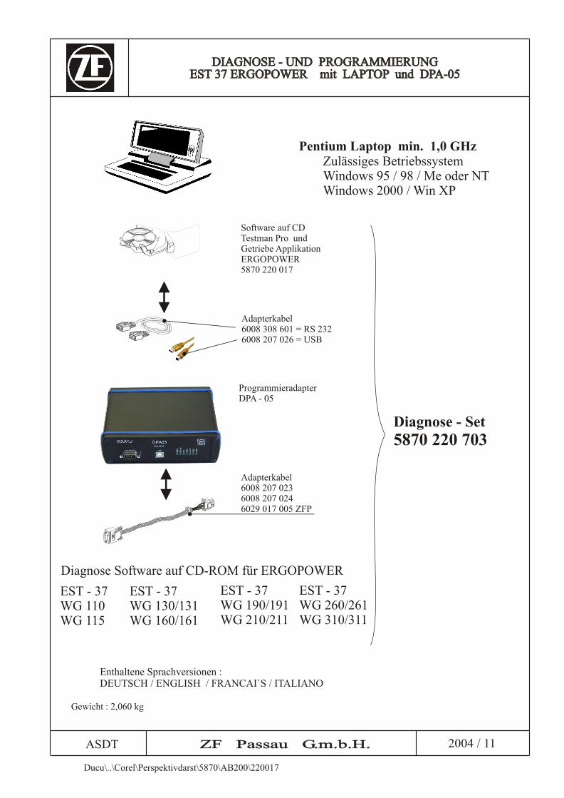
Diagnose - Set5870 220 703
ASDT ZF Passau G.m.b.H.ZF Passau G.m.b.H. 2004 / 11
DIAGNOSE - UND PROGRAMMIERUNGEST 37 ERGOPOWER mit LAPTOP und DPA-05
DIAGNOSE - UND PROGRAMMIERUNGEST 37 ERGOPOWER mit LAPTOP und DPA-05
Zulässiges BetriebssystemWindows 95 / 98 / Me oder NTWindows 2000 / Win XP
Adapterkabel 6008 308 601 = RS 2326008 207 026 = USB
Software Testman Pro undGetriebe ApplikationERGOPOWER 5870 220 017
auf CD
Programmieradapter DPA - 05
Diagnose Software auf CD-ROM für ERGOPOWER
EST - 37 WG 130/131WG 160/161
Enthaltene Sprachversionen : DEUTSCH / ENGLISH / FRANCAI`S / ITALIANO
EST - 37 WG 190/191WG 210/211
EST - 37 WG 260/261WG 310/311
EST - 37 WG 110WG 115
Adapterkabel 6008 207 0236008 207 0246029 017 005 ZFP
Ducu\..\Corel\Perspektivdarst\5870\AB200\220017
Pentium Laptop min. 1,0 GHz
Gewicht : 2,060 kg

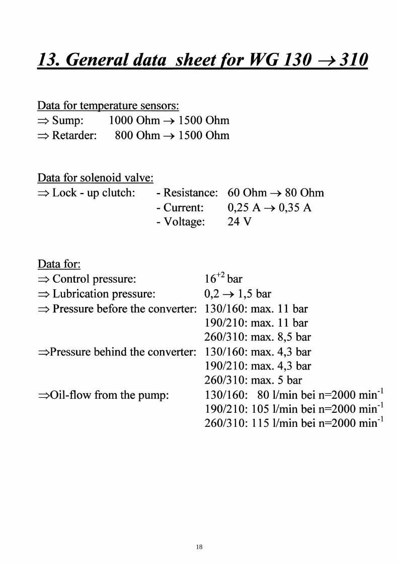
16

17
18
ZF Friedrichshafen AG 03-05-13 Faultcodes ERGO-Control EST37A
TE-AB N:\Astt\Elektrikneu\Fc_37_V912.doc Seite 3 von 53
1 Introduction
1.1 Abbreviations
o.c. open circuit s.c. short circuit OP-Mode operating mode TCU transmission control unit EEC electronic engine controller PTO power take off
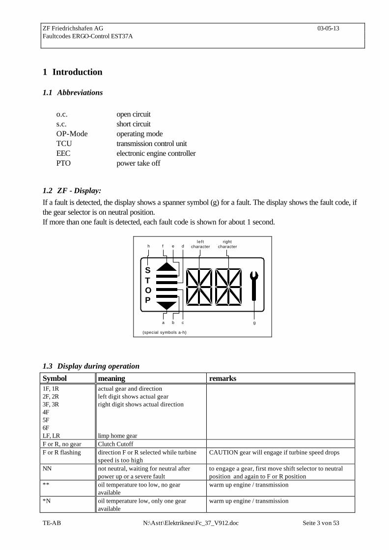
1.2 ZF - Display: If a fault is detected, the display shows a spanner symbol (g) for a fault. The display shows the fault code, if the gear selector is on neutral position. If more than one fault is detected, each fault code is shown for about 1 second.
STOP
h f e d
a b c g
(special symbols a-h)
le f tcharacter
rightcharacter
1.3 Display during operation
Symbol meaning remarks 1F, 1R 2F, 2R 3F, 3R 4F 5F 6F LF, LR
actual gear and direction left digit shows actual gear right digit shows actual direction limp home gear
F or R, no gear Clutch Cutoff F or R flashing direction F or R selected while turbine
speed is too high CAUTION gear will engage if turbine speed drops
NN not neutral, waiting for neutral after power up or a severe fault
to engage a gear, first move shift selector to neutral position and again to F or R position
** oil temperature too low, no gear available
warm up engine / transmission
*N oil temperature low, only one gear available
warm up engine / transmission

ZF Friedrichshafen AG 03-05-13 Faultcodes ERGO-Control EST37A
TE-AB N:\Astt\Elektrikneu\Fc_37_V912.doc Seite 4 von 53
1 bar (special symbol)
manual mode 1st gear
2 bars manual mode 2nd gear 3 bars manual mode 3rd gear 4 bars manual mode 4th gear and also 5th and 6th
gear in 6WG
4 bars and 2 arrows automatic mode Bars flashing 6 WG: converter lockup clutch open
4 WG: Downshift mode activ
difference of engine and turbine speed above a certain limit and lockup clutch not activated
Spanner at least one fault activ select neutral to get fault code displayed Fault code see faultcode list WS warning sump temperature changes between actual gear/direction while driving, in
neutral only displayed if no fault is detected (spanner) WR warning retarder temperature changes between actual gear/direction while driving, in
neutral only displayed if no fault is detected (spanner) WT warning torque converter temperature changes between actual gear/direction while driving, in
neutral only displayed if no fault is detected (spanner) WE warning high engine speed changes between actual gear/direction while driving, in
neutral only displayed if no fault is detected (spanner) PN direction F or R selected while parking
brake engaged transmission in neutral until parking brake is released CAUTION: vehicle starts to move after release of parking brake
EE flashing no communication with display checked wiring from TCU to display
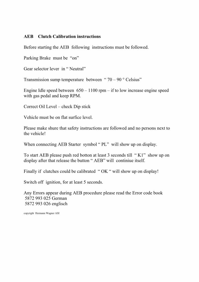
AEB Clutch Calibration instructions Before starting the AEB following instructions must be followed. Parking Brake must be “on” Gear selector lever in “ Neutral” Transmission sump temperature between “ 70 – 90 ° Celsius” Engine Idle speed between 650 – 1100 rpm – if to low increase engine speed with gas pedal and keep RPM. Correct Oil Level – check Dip stick Vehicle must be on flat surfice level. Please make shure that safety instructions are followed and no persons next to the vehicle! When connecting AEB Starter symbol “ PL” will show up on display. To start AEB please push red botton at least 3 seconds till “ K1” show up on display after that release the button “ AEB” will continiue itself. Finally if clutches could be calibrated “ OK “ will show up on display! Switch off ignition, for at least 5 seconds. Any Errors appear during AEB procedure please read the Error code book 5872 993 025 German 5872 993 026 englisch copyright Hermann Wagner ASI

ZF Friedrichshafen AG 03-05-13 Faultcodes ERGO-Control EST37A
TE-AB N:\Astt\Elektrikneu\Fc_37_V912.doc Seite 5 von 53
1.4 Display during AEB-Mode
symbol meaning remarks PL AEB - Starter is plugged at the
diagnostic plug
ST AEB-Starter-button is pressed
K1..K4,KV,KR calibrating clutch K1..K4, KV or KR resp.
_ and Kx wait for start, initialization of clutch Kx, x: 1, 2, 3, 4, V, R
≡ and Kx fast fill time determination of clutch Kx
= and Kx compensating pressure determination of clutch Kx
OK calibration for all clutches finished Transmissions stays in neutral, you have to restart the TCU (ignition off/on) after removing AEB-Starter
STOP AEB canceled (activation stopped) Transmissions stays in neutral, you have to restart the TCU (ignition off/on)
STOP and Kx AEB stopped, clutch Kx can't be calibrated
Transmissions stays in neutral, you have to restart the TCU (ignition off/on)
Spanner and Kx Kx couldn't be calibrated, AEB finished Transmissions stays in neutral, you have to restart the TCU (ignition off/on)
∆ E engine speed too low, ð raise engine speed
∇ E engine speed too high, ð lower engine speed
∆ T transmission oil temperature too low, ð heat up transmission
∇ T transmission oil temperature too high ð cool down transmission
FT transmission temperature not in defined range during calibration
Transmissions stays in neutral, you have to restart the TCU (ignition off/on)
FB operating mode not NORMAL or transmission temperature sensor defective or storing of Calibrated values to EEPROM-has failed.
Transmissions stays in neutral, you have to restart the TCU (ignition off/on)
FO Outputspeed_not_zero Transmissions stays in neutral, you have to restart the TCU (ignition off/on)
FN Shift lever not in Neutral position Transmissions stays in neutral, you have to restart the TCU (ignition off/on)
FP Parkbrake_not_applied Transmissions stays in neutral, you have to restart the TCU (ignition off/on)
STOP AEB - Starter was used incorrect or is defective. Wrong device or wrong cable used
Transmissions stays in neutral, you have to restart the TCU (ignition off/on)

ZF Friedrichshafen AG 03-05-13 Faultcodes ERGO-Control EST37A
TE-AB N:\Astt\Elektrikneu\Fc_37_V912.doc Seite 6 von 53
2 definition of operating modes
NORMAL:
There's no failure detected in the transmission-system or the failure has no or slight effects on
transmission control. TCU will work without or in special cases with little limitations. (see following
table)
SUBSTITUTE CLUTCH CONTROL:
TCU can't change the gears or the direction under the control of the normal clutch modulation. TCU
uses the substitute strategy for clutch control. All modulations are only time controlled. (Comparable
with EST 25)
LIMP-HOME:
The detected failure in the system has strong limitations to transmission control. TCU can engage only
one gear in each direction. In some cases only one direction will be possible.
TCU will shift the transmission into neutral at the first occurrence of the failure. First, the operator
must shift the gear selector into neutral position.
If output speed is less than a threshold for neutral to gear and the operator shifts the gear selector into
forward or reverse, the TCU will select the limp-home gear .
If output speed is less than a threshold for reversal speed and TCU has changed into the limp-home
gear and the operator selects a shuttle shift, TCU will shift immediately into the limp-home gear of the
selected direction.
If output speed is greater than the threshold, TCU will shift the transmission into neutral. The operator
has to slow down the vehicle and must shift the gear selector into neutral position.
TRANSMISSION-SHUTDOWN:
TCU has detected a severe failure that disables control of the transmission.
TCU will shut off the solenoid valves for the clutches and also the common power supply (VPS1).
Transmission shifts to Neutral. The park brake will operate normally, also the other functions which
use ADM 1 to ADM 8.
The operator has to slow down the vehicle. The transmission will stay in neutral.
TCU-SHUTDOWN:
TCU has detected a severe failure that disables control of system.
TCU will shut off all solenoid valves and also both common power supplies (VPS1, VPS2). The park
brake will engage, also all functions are disabled which use ADM 1 to ADM 8.
The transmission will stay in neutral.
ZF Friedrichshafen AG description of fault codes for ERGO-Control 97-09-18
TE-AB N:\Astt\Elektrikneu\Fc_37_V912.doc Seite 7 von 53
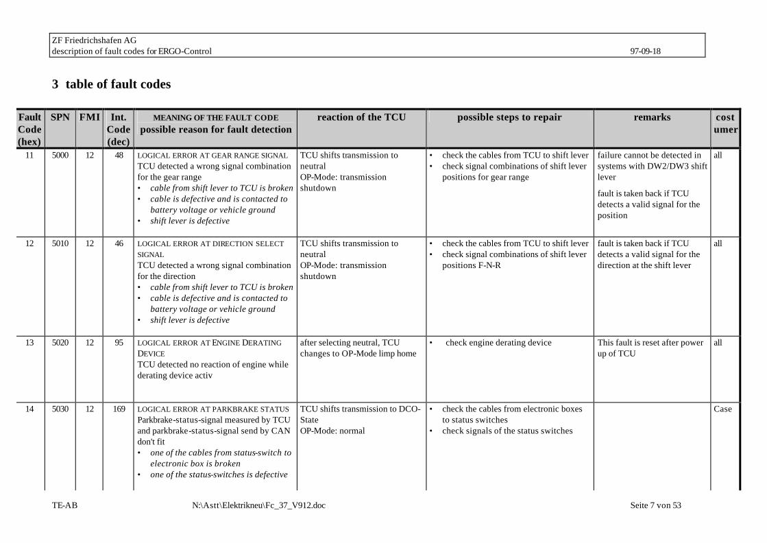
3 table of fault codes
Fault Code (hex)
SPN FMI Int. Code (dec)
MEANING OF THE FAULT CODE possible reason for fault detection
reaction of the TCU possible steps to repair remarks costumer
11 5000 12 48 LOGICAL ERROR AT GEAR RANGE SIGNAL TCU detected a wrong signal combination for the gear range • cable from shift lever to TCU is broken • cable is defective and is contacted to
battery voltage or vehicle ground • shift lever is defective
TCU shifts transmission to neutral OP-Mode: transmission shutdown
• check the cables from TCU to shift lever • check signal combinations of shift lever
positions for gear range
failure cannot be detected in systems with DW2/DW3 shift lever
fault is taken back if TCU detects a valid signal for the position
all
12 5010 12 46 LOGICAL ERROR AT DIRECTION SELECT SIGNAL TCU detected a wrong signal combination for the direction • cable from shift lever to TCU is broken • cable is defective and is contacted to
battery voltage or vehicle ground • shift lever is defective
TCU shifts transmission to neutral OP-Mode: transmission shutdown
• check the cables from TCU to shift lever • check signal combinations of shift lever
positions F-N-R
fault is taken back if TCU detects a valid signal for the direction at the shift lever
all
13 5020 12 95 LOGICAL ERROR AT ENGINE DERATING DEVICE TCU detected no reaction of engine while derating device activ
after selecting neutral, TCU changes to OP-Mode limp home
• check engine derating device This fault is reset after power up of TCU
all
14 5030 12 169 LOGICAL ERROR AT PARKBRAKE STATUS Parkbrake-status-signal measured by TCU and parkbrake-status-signal send by CAN don't fit • one of the cables from status-switch to
electronic box is broken • one of the status-switches is defective
TCU shifts transmission to DCO-State OP-Mode: normal
• check the cables from electronic boxes to status switches
• check signals of the status switches
Case

ZF Friedrichshafen AG description of fault codes for ERGO-Control 97-09-18
TE-AB N:\Astt\Elektrikneu\Fc_37_V912.doc Seite 8 von 53
Fault Code (hex)
SPN FMI Int. Code (dec)
MEANING OF THE FAULT CODE possible reason for fault detection
reaction of the TCU possible steps to repair remarks costumer
15 5040 12 176 LOGICAL ERROR AT DIRECTION SELECT SIGNAL 2. SHIFT LEVER TCU detected a wrong signal combination for the direction • cable from shift lever 2 to TCU is
broken • cable is defective and is contacted to
battery voltage or vehicle ground • shift lever is defective
TCU shifts transmission to neutral if selector activ OP-Mode: transmission shutdown if selector activ
• check the cables from TCU to shift lever 2
• check signal combinations of shift lever positions F-N-R
fault is taken back if TCU detects a valid neutral signal for the direction at the shift lever
all case
16 5050 12 178 LOGICAL ERROR AT AXLE CONNECTION feedback axle connection measured by TCU and output signal axle connection don't fit • axle can’t be connected or
disconnected due to mechanical problem
• one of the cables from feedback axle connection -switch to TCU is broken
OP-Mode: normal • check the cables from TCU to feedback axle connection switch
• check signals of the feedback axle connection switch
all
17 5060 4 148 S.C. TO GROUND AT CUSTOMER SPECIFIC FUNCTION NO. 1 TCU detected a wrong voltage at the output pin, that looks like a s.c. to vehicle ground • cable is defective and is contacted to
vehicle ground • customer specific function no. 1 device
has an internal defect • connector pin is contacted to vehicle
ground
customer specific • check the cable from TCU to customer specific function no. 1 device
• check the connectors from customer specific function no. 1 to TCU
• check the resistance of customer specific function no. 1 device
1) see chapter 4 Z-Funktion1
18 5060 3 150 S.C. TO BATTERY VOLTAGE AT CUSTOMER SPECIFIC FUNCTION NO. 1 TCU detected a wrong voltage at the
customer specific • check the cable from TCU to customer specific function no. 1 device
• check the connectors from customer
1) see chapter 4 Z-Funktion1

ZF Friedrichshafen AG description of fault codes for ERGO-Control 97-09-18
TE-AB N:\Astt\Elektrikneu\Fc_37_V912.doc Seite 9 von 53
Fault Code (hex)
SPN FMI Int. Code (dec)
MEANING OF THE FAULT CODE possible reason for fault detection
reaction of the TCU possible steps to repair remarks costumer
output pin, that looks like a s.c. to battery voltage • cable is defective and is contacted to
battery voltage • customer specific function no. 1 device
has an internal defect • connector pin is contacted to battery
voltage
specific function no. 1 to TCU • check the resistance of customer
specific function no. 1 device
19 5060 5 149 O.C. AT CUSTOMER SPECIFIC FUNCTION NO. 1 TCU detected a wrong voltage at the output pin, that looks like a o.c. for this output pin • cable is defective and has no
connection to TCU • customer specific function no. 1 device
has an internal defect • connector has no connection to TCU
customer specific • check the cable from TCU to customer specific function no. 1 device
• check the connectors from customer specific function no. 1 device to TCU
• check the resistance of customer specific function no. 1 device
1) see chapter 4 Z-Funktion1
1A 5070 4 151 S.C. TO GROUND AT CUSTOMER SPECIFIC FUNCTION NO. 2 TCU detected a wrong voltage at the output pin, that looks like a s.c. to vehicle ground • cable is defective and is contacted to
vehicle ground • customer specific function no. 2 device
has an internal defect • connector pin is contacted to vehicle
ground
customer specific • check the cable from TCU to customer specific function no. 2 device
• check the connectors from customer specific function no. 2 device to TCU
• check the resistance of customer specific function no. 2 device
1) see chapter 4 Z-Funktion2
1B 5070 3 153 S.C. TO BATTERY VOLTAGE AT CUSTOMER SPECIFIC FUNCTION NO. 2 TCU detected a wrong voltage at the
customer specific • check the cable from TCU to customer specific function no. 2 device
• check the connectors from customer
1) see chapter 4 Z-Funktion2
ZF Friedrichshafen AG description of fault codes for ERGO-Control 97-09-18
TE-AB N:\Astt\Elektrikneu\Fc_37_V912.doc Seite 10 von 53
Fault Code (hex)
SPN FMI Int. Code (dec)
MEANING OF THE FAULT CODE possible reason for fault detection
reaction of the TCU possible steps to repair remarks costumer
output pin, that looks like a s.c. to battery voltage • cable is defective and is contacted to
battery voltage • customer specific function no. 2 device
has an internal defect • connector pin is contacted to battery
voltage
specific function no. 2 device to TCU • check the resistance of customer
specific function no. 2 device
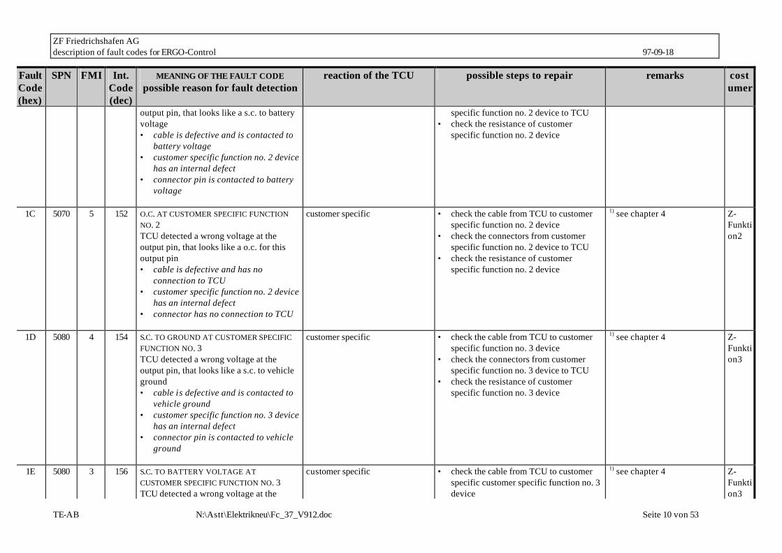
1C 5070 5 152 O.C. AT CUSTOMER SPECIFIC FUNCTION NO. 2 TCU detected a wrong voltage at the output pin, that looks like a o.c. for this output pin • cable is defective and has no
connection to TCU • customer specific function no. 2 device
has an internal defect • connector has no connection to TCU
customer specific • check the cable from TCU to customer specific function no. 2 device
• check the connectors from customer specific function no. 2 device to TCU
• check the resistance of customer specific function no. 2 device
1) see chapter 4 Z-Funktion2
1D 5080 4 154 S.C. TO GROUND AT CUSTOMER SPECIFIC FUNCTION NO. 3 TCU detected a wrong voltage at the output pin, that looks like a s.c. to vehicle ground • cable is defective and is contacted to
vehicle ground • customer specific function no. 3 device
has an internal defect • connector pin is contacted to vehicle
ground
customer specific • check the cable from TCU to customer specific function no. 3 device
• check the connectors from customer specific function no. 3 device to TCU
• check the resistance of customer specific function no. 3 device
1) see chapter 4 Z-Funktion3
1E 5080 3 156 S.C. TO BATTERY VOLTAGE AT CUSTOMER SPECIFIC FUNCTION NO. 3 TCU detected a wrong voltage at the
customer specific • check the cable from TCU to customer specific customer specific function no. 3 device
1) see chapter 4 Z-Funktion3

ZF Friedrichshafen AG description of fault codes for ERGO-Control 97-09-18
TE-AB N:\Astt\Elektrikneu\Fc_37_V912.doc Seite 11 von 53
Fault Code (hex)
SPN FMI Int. Code (dec)
MEANING OF THE FAULT CODE possible reason for fault detection
reaction of the TCU possible steps to repair remarks costumer
output pin, that looks like a s.c. to battery voltage • cable is defective and is contacted to
battery voltage • customer specific function no. 3
device has an internal defect • connector pin is contacted to battery
voltage
• check the connectors from customer specific function no. 3 device to TCU
• check the resistance of customer specific function no. 3 device
1F 5080 5 155 O.C. AT CUSTOMER SPECIFIC FUNCTION NO. 3 TCU detected a wrong voltage at the output pin, that looks like a o.c. for this output pin • cable is defective and has no
connection to TCU • customer specific function no. 3
device has an internal defect • connector has no connection to TCU
customer specific • check the cable from TCU to customer specific function no. 3 device
• check the connectors from customer specific function no. 3 device to TCU
• check the resistance of customer specific function no. 3 device
1) see chapter 4 Z-Funktion3
21 5090 3 32 S.C. TO BATTERY VOLTAGE AT CLUTCH CUTOFF INPUT the measured voltage is too high: • cable is defective and is contacted to
battery voltage • clutch cut off sensor has an internal
defect • connector pin is contacted to battery
voltage
clutch cutoff function is disabled OP-Mode: normal
• check the cable from TCU to the sensor • check the connectors • check the clutch cutoff sensor
John Deere
22 5090 4 29 S.C. TO GROUND OR O.C. AT CLUTCH CUTOFF INPUT the measured voltage is too low: • cable is defective and is contacted to
clutch cutoff function is disabled OP-Mode: normal
• check the cable from TCU to the sensor • check the connectors • check the clutch cutoff sensor
John Deere

ZF Friedrichshafen AG description of fault codes for ERGO-Control 97-09-18
TE-AB N:\Astt\Elektrikneu\Fc_37_V912.doc Seite 12 von 53
Fault Code (hex)
SPN FMI Int. Code (dec)
MEANING OF THE FAULT CODE possible reason for fault detection
reaction of the TCU possible steps to repair remarks costumer
vehicle ground • cable has no connection to TCU • clutch cut off sensor has an internal
defect • connector pin is contacted to vehicle
ground or is broken
23 5100 3 69 S.C. TO BATTERY VOLTAGE AT LOAD SENSOR INPUT the measured voltage is too high: • cable is defective and is contacted to
battery voltage • load sensor has an internal defect • connector pin is contacted to battery
voltage
retarder function is affected TCU uses default load OP-Mode: normal
• check the cable from TCU to the sensor • check the connectors • check the load sensor sensor • check the assembly tolerances of load
sensor
availability of retarder depends on default load
ohne CAN
24 5100 4 70 S.C. TO GROUND OR O.C. AT LOAD SENSOR INPUT the measured voltage is too low: • cable is defective and is contacted to
vehicle ground • cable has no connection to TCU • load sensor has an internal defect • connector pin is contacted to vehicle
ground or is broken
retarder function is affected TCU uses default load OP-Mode: normal
• check the cable from TCU to the sensor • check the connectors • check the load sensor sensor • check the assembly tolerances of load
sensor
availability of retarder depends on default load
ohne CAN
25 5110 3 33 S.C. TO BATTERY VOLTAGE OR O.C. AT TRANSMISSION SUMP TEMPERATURE SENSOR INPUT the measured voltage is too high: • cable is defective and is contacted to
battery voltage • cable has no connection to TCU • temperature sensor has an internal
defect
no reaction, TCU uses default temperature OP-Mode: normal
• check the cable from TCU to the sensor • check the connectors • check the temperature sensor
all, Sisu

ZF Friedrichshafen AG description of fault codes for ERGO-Control 97-09-18
TE-AB N:\Astt\Elektrikneu\Fc_37_V912.doc Seite 13 von 53
Fault Code (hex)
SPN FMI Int. Code (dec)
MEANING OF THE FAULT CODE possible reason for fault detection
reaction of the TCU possible steps to repair remarks costumer
• connector pin is contacted to battery voltage or is broken
26 5110 4 30 S.C. TO GROUND AT TRANSMISSION SUMP
TEMPERATURE SENSOR INPUT the measured voltage is too low: • cable is defective and is contacted to
vehicle ground • temperature sensor has an internal
defect • connector pin is contacted to vehicle
ground
no reaction, TCU uses default temperature OP-Mode: normal
• check the cable from TCU to the sensor • check the connectors • check the temperature sensor
all, Sisu
27 5120 3 76 S.C. TO BATTERY VOLTAGE OR O.C. AT RETARDER TEMPERATURE SENSOR INPUT the measured voltage is too high: • cable is defective and is contacted to
battery voltage • cable has no connection to TCU • temperature sensor has an internal
defect • connector pin is contacted to battery
voltage or is broken
no reaction, TCU uses default temperature OP-Mode: normal
• check the cable from TCU to the sensor • check the connectors • check the temperature sensor
6WG
28 5120 4 74 S.C. TO GROUND AT RETARDER TEMPERATURE SENSOR INPUT the measured voltage is too low: • cable is defective and is contacted to
vehicle ground • temperature sensor has an internal
defect • connector pin is contacted to vehicle
ground
no reaction, TCU uses default temperature OP-Mode: normal
• check the cable from TCU to the sensor • check the connectors • check the temperature sensor
6WG
ZF Friedrichshafen AG description of fault codes for ERGO-Control 97-09-18
TE-AB N:\Astt\Elektrikneu\Fc_37_V912.doc Seite 14 von 53
Fault Code (hex)
SPN FMI Int. Code (dec)
MEANING OF THE FAULT CODE possible reason for fault detection
reaction of the TCU possible steps to repair remarks costumer
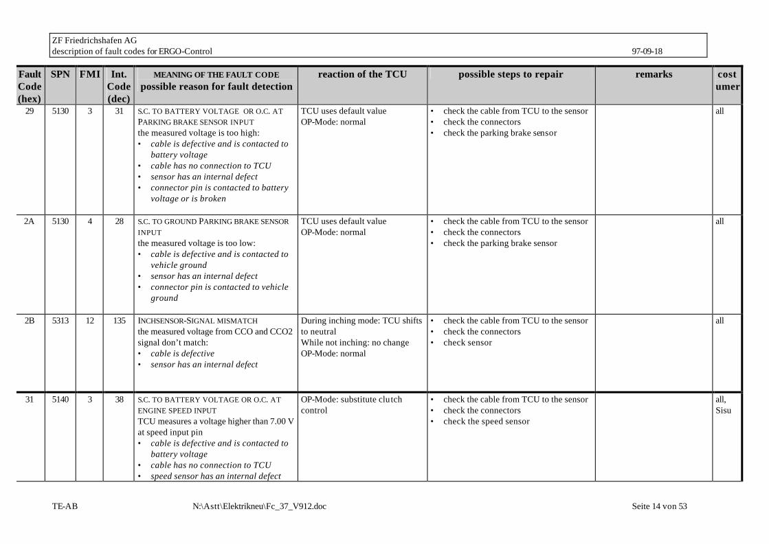
29 5130 3 31 S.C. TO BATTERY VOLTAGE OR O.C. AT PARKING BRAKE SENSOR INPUT the measured voltage is too high: • cable is defective and is contacted to
battery voltage • cable has no connection to TCU • sensor has an internal defect • connector pin is contacted to battery
voltage or is broken
TCU uses default value OP-Mode: normal
• check the cable from TCU to the sensor • check the connectors • check the parking brake sensor
all
2A 5130 4 28 S.C. TO GROUND PARKING BRAKE SENSOR INPUT the measured voltage is too low: • cable is defective and is contacted to
vehicle ground • sensor has an internal defect • connector pin is contacted to vehicle
ground
TCU uses default value OP-Mode: normal
• check the cable from TCU to the sensor • check the connectors • check the parking brake sensor
all
2B 5313 12 135 INCHSENSOR-SIGNAL MISMATCH the measured voltage from CCO and CCO2 signal don’t match: • cable is defective • sensor has an internal defect
During inching mode: TCU shifts to neutral While not inching: no change OP-Mode: normal
• check the cable from TCU to the sensor • check the connectors • check sensor
all
31 5140 3 38 S.C. TO BATTERY VOLTAGE OR O.C. AT ENGINE SPEED INPUT TCU measures a voltage higher than 7.00 V at speed input pin • cable is defective and is contacted to
battery voltage • cable has no connection to TCU • speed sensor has an internal defect
OP-Mode: substitute clutch control
• check the cable from TCU to the sensor • check the connectors • check the speed sensor
all, Sisu

ZF Friedrichshafen AG description of fault codes for ERGO-Control 97-09-18
TE-AB N:\Astt\Elektrikneu\Fc_37_V912.doc Seite 15 von 53
Fault Code (hex)
SPN FMI Int. Code (dec)
MEANING OF THE FAULT CODE possible reason for fault detection
reaction of the TCU possible steps to repair remarks costumer
• connector pin is contacted to battery voltage or has no contact
32 5140 4 34 S.C. TO GROUND AT ENGINE SPEED INPUT
TCU measures a voltage less than 0.45V at speed input pin • cable / connector is defective and is
contacted to vehicle ground • speed sensor has an internal defect
OP-Mode: substitute clutch control
• check the cable from TCU to the sensor • check the connectors • check the speed sensor
all, Sisu
33 5140 12 42 LOGICAL ERROR AT ENGINE SPEED INPUT TCU measures a engine speed over a threshold and the next moment the measured speed is zero • cable / connector is defective and has
bad contact • speed sensor has an internal defect • sensor gap has the wrong size
OP-Mode: substitute clutch control
• check the cable from TCU to the sensor • check the connectors • check the speed sensor • check the sensor gap
This fault is reset after power up of TCU
all, Sisu
34 5150 3 39 S.C. TO BATTERY VOLTAGE OR O.C. AT TURBINE SPEED INPUT TCU measures a voltage higher than 7.00 V at speed input pin • cable is defective and is contacted to
battery voltage • cable has no connection to TCU • speed sensor has an internal defect • connector pin is contacted to battery
voltage or has no contact
OP-Mode: substitute clutch control if a failure is existing at output speed, TCU shifts to neutral OP-Mode: limp home
• check the cable from TCU to the sensor • check the connectors • check the speed sensor
all, Sisu
35 5150 4 35 S.C. TO GROUND AT TURBINE SPEED INPUT TCU measures a voltage less than 0.45V at speed input pin
OP-Mode: substitute clutch control if a failure is existing at output speed,
• check the cable from TCU to the sensor • check the connectors • check the speed sensor
all, Sisu

ZF Friedrichshafen AG description of fault codes for ERGO-Control 97-09-18
TE-AB N:\Astt\Elektrikneu\Fc_37_V912.doc Seite 16 von 53
Fault Code (hex)
SPN FMI Int. Code (dec)
MEANING OF THE FAULT CODE possible reason for fault detection
reaction of the TCU possible steps to repair remarks costumer
• cable / connector is defective and is contacted to vehicle ground
• speed sensor has an internal defect
TCU shifts to neutral OP-Mode: limp home
36 5150 12 43 LOGICAL ERROR AT TURBINE SPEED INPUT TCU measures a turbine speed over a threshold and at the next moment the measured speed is zero • cable / connector is defective and has
bad contact • speed sensor has an internal defect • sensor gap has the wrong size
OP-Mode: substitute clutch control if a failure is existing at output speed, TCU shifts to neutral OP-Mode: limp home
• check the cable from TCU to the sensor • check the connectors • check the speed sensor • check the sensor gap
This fault is reset after power up of TCU
all, Sisu
37 5160 3 40 S.C. TO BATTERY VOLTAGE OR O.C. AT INTERNAL SPEED INPUT TCU measures a voltage higher than 7.00 V at speed input pin • cable is defective and is contacted to
battery voltage • cable has no connection to TCU • speed sensor has an internal defect • connector pin is contacted to battery
voltage or has no contact
OP-Mode: substitute clutch control
• check the cable from TCU to the sensor • check the connectors • check the speed sensor
all, Sisu
38 5160 4 36 S.C. TO GROUND AT INTERNAL SPEED INPUT TCU measures a voltage less than 0.45V at speed input pin • cable / connector is defective and is
contacted to vehicle ground • speed sensor has an internal defect
OP-Mode: substitute clutch control
• check the cable from TCU to the sensor • check the connectors • check the speed sensor
all, Sisu
39 5160 12 44 LOGICAL ERROR AT INTERNAL SPEED INPUT
OP-Mode: substitute clutch control
• check the cable from TCU to the sensor • check the connectors
This fault is reset after power up of TCU
all, Sisu
ZF Friedrichshafen AG description of fault codes for ERGO-Control 97-09-18
TE-AB N:\Astt\Elektrikneu\Fc_37_V912.doc Seite 17 von 53
Fault Code (hex)
SPN FMI Int. Code (dec)
MEANING OF THE FAULT CODE possible reason for fault detection
reaction of the TCU possible steps to repair remarks costumer
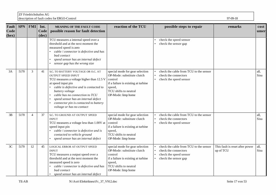
TCU measures a internal speed over a threshold and at the next moment the measured speed is zero • cable / connector is defective and has
bad contact • speed sensor has an internal defect • sensor gap has the wrong size
• check the speed sensor • check the sensor gap
3A 5170 3 41 S.C. TO BATTERY VOLTAGE OR O.C. AT OUTPUT SPEED INPUT TCU measures a voltage higher than 12.5 V at speed input pin • cable is defective and is contacted to
battery voltage • cable has no connection to TCU • speed sensor has an internal defect • connector pin is contacted to battery
voltage or has no contact
special mode for gear selection OP-Mode: substitute clutch control if a failure is existing at turbine speed, TCU shifts to neutral OP-Mode: limp home
• check the cable from TCU to the sensor • check the connectors • check the speed sensor
all, Sisu
3B 5170 4 37 S.C. TO GROUND AT OUTPUT SPEED INPUT TCU measures a voltage less than 1.00V at speed input pin • cable / connector is defective and is
contacted to vehicle ground • speed sensor has an internal defect
special mode for gear selection OP-Mode: substitute clutch control if a failure is existing at turbine speed, TCU shifts to neutral OP-Mode: limp home
• check the cable from TCU to the sensor • check the connectors • check the speed sensor
all, Sisu
3C 5170 12 45 LOGICAL ERROR AT OUTPUT SPEED INPUT TCU measures a output speed over a threshold and at the next moment the measured speed is zero • cable / connector is defective and has
bad contact • speed sensor has an internal defect
special mode for gear selection OP-Mode: substitute clutch control if a failure is existing at turbine speed, TCU shifts to neutral OP-Mode: limp home
• check the cable from TCU to the sensor • check the connectors • check the speed sensor • check the sensor gap
This fault is reset after power up of TCU
all, Sisu
ZF Friedrichshafen AG description of fault codes for ERGO-Control 97-09-18
TE-AB N:\Astt\Elektrikneu\Fc_37_V912.doc Seite 18 von 53
Fault Code (hex)
SPN FMI Int. Code (dec)
MEANING OF THE FAULT CODE possible reason for fault detection
reaction of the TCU possible steps to repair remarks costumer
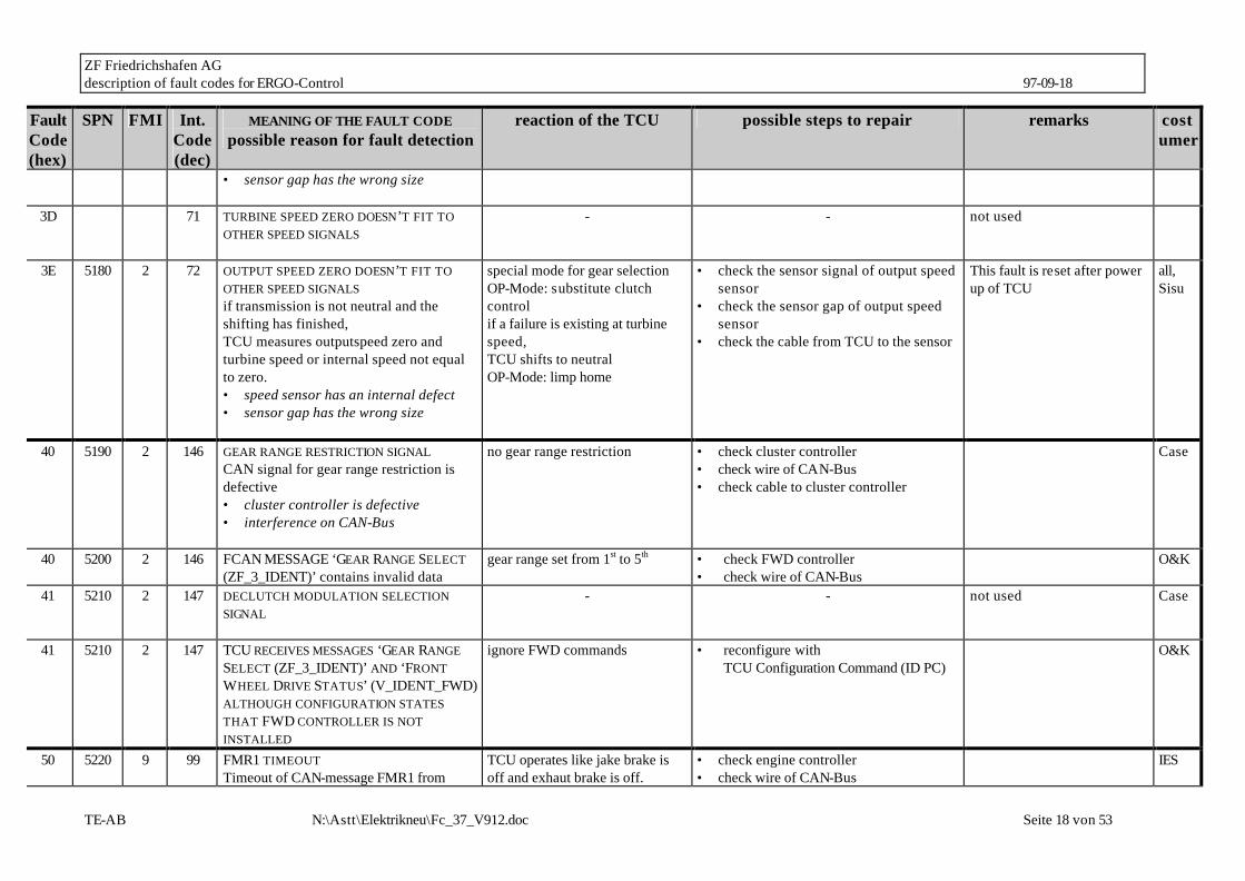
• sensor gap has the wrong size
3D 71 TURBINE SPEED ZERO DOESN’T FIT TO OTHER SPEED SIGNALS
- - not used
3E 5180 2 72 OUTPUT SPEED ZERO DOESN’T FIT TO OTHER SPEED SIGNALS if transmission is not neutral and the shifting has finished, TCU measures outputspeed zero and turbine speed or internal speed not equal to zero. • speed sensor has an internal defect • sensor gap has the wrong size
special mode for gear selection OP-Mode: substitute clutch control if a failure is existing at turbine speed, TCU shifts to neutral OP-Mode: limp home
• check the sensor signal of output speed sensor
• check the sensor gap of output speed sensor
• check the cable from TCU to the sensor
This fault is reset after power up of TCU
all, Sisu
40 5190 2 146 GEAR RANGE RESTRICTION SIGNAL CAN signal for gear range restriction is defective • cluster controller is defective • interference on CAN-Bus
no gear range restriction • check cluster controller • check wire of CAN-Bus • check cable to cluster controller
Case
40 5200 2 146 FCAN MESSAGE ‘GEAR RANGE SELECT (ZF_3_IDENT)’ contains invalid data
gear range set from 1st to 5th • check FWD controller • check wire of CAN-Bus
O&K
41 5210 2 147 DECLUTCH MODULATION SELECTION SIGNAL
- - not used Case
41 5210 2 147 TCU RECEIVES MESSAGES ‘GEAR RANGE SELECT (ZF_3_IDENT)’ AND ‘FRONT WHEEL DRIVE STATUS’ (V_IDENT_FWD) ALTHOUGH CONFIGURATION STATES THAT FWD CONTROLLER IS NOT INSTALLED
ignore FWD commands • reconfigure with TCU Configuration Command (ID PC)
O&K
50 5220 9 99 FMR1 TIMEOUT Timeout of CAN-message FMR1 from
TCU operates like jake brake is off and exhaut brake is off.
• check engine controller • check wire of CAN-Bus
IES

ZF Friedrichshafen AG description of fault codes for ERGO-Control 97-09-18
TE-AB N:\Astt\Elektrikneu\Fc_37_V912.doc Seite 19 von 53
Fault Code (hex)
SPN FMI Int. Code (dec)
MEANING OF THE FAULT CODE possible reason for fault detection
reaction of the TCU possible steps to repair remarks costumer
engine controller • interference on CAN-Bus • CAN wire/connector is broken • CAN wire/connector is defective and
has contact to vehicle ground or battery voltage
• engine controller is defective
OP-Mode: normal • check cable to engine controller
51 5230 9 100 FMR2 TIMEOUT Timeout of CAN-message FMR2 from engine controller • interference on CAN-Bus • CAN wire/connector is broken • CAN wire/connector is defective and
has contact to vehicle ground or battery voltage
• engine controller is defective
OP-Mode: substitute clutch control
• check engine controller • check wire of CAN-Bus • check cable to engine controller
IES
52 5240 9 101 EAMODUL1 TIMEOUT Timeout of CAN-message EAM1 from I/O - controller • interference on CAN-Bus • CAN wire/connector is broken • CAN wire/connector is defective and
has contact to vehicle ground or battery voltage
TCU shifts to neutral and uses substitute gear selector OP-Mode: normal
• check I/O controller • check wire of CAN-Bus • check cable to I/O controller
Liebherr
53 5250 9 102 ABS TIMEOUT Timeout of CAN-message ABS from ABS - controller • interference on CAN-Bus • CAN wire/connector is broken • CAN wire/connector is defective and
has contact to vehicle ground or battery voltage
no reaction • check ABS controller • check wire of CAN-Bus • check cable to ABS controller
IES
ZF Friedrichshafen AG description of fault codes for ERGO-Control 97-09-18
TE-AB N:\Astt\Elektrikneu\Fc_37_V912.doc Seite 20 von 53
Fault Code (hex)
SPN FMI Int. Code (dec)
MEANING OF THE FAULT CODE possible reason for fault detection
reaction of the TCU possible steps to repair remarks costumer
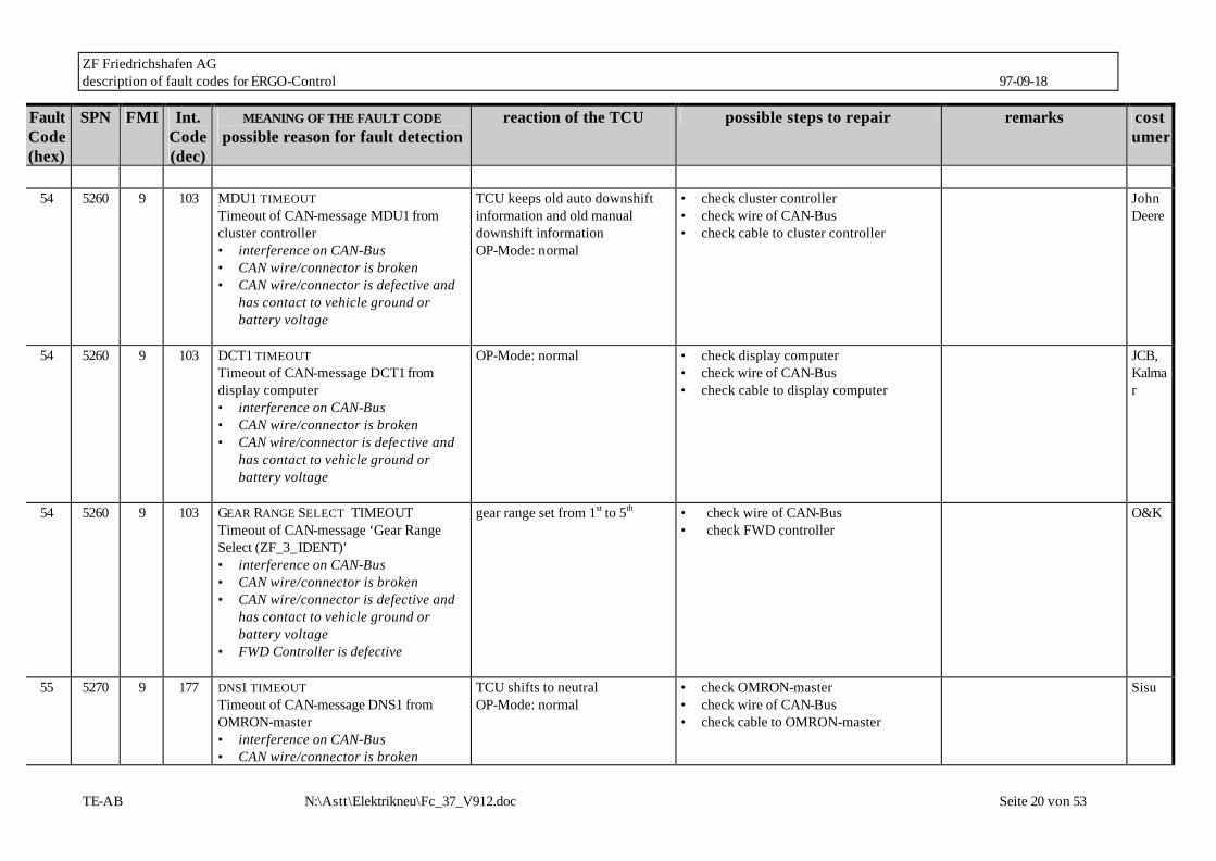
54 5260 9 103 MDU1 TIMEOUT Timeout of CAN-message MDU1 from cluster controller • interference on CAN-Bus • CAN wire/connector is broken • CAN wire/connector is defective and
has contact to vehicle ground or battery voltage
TCU keeps old auto downshift information and old manual downshift information OP-Mode: normal
• check cluster controller • check wire of CAN-Bus • check cable to cluster controller
John Deere
54 5260 9 103 DCT1 TIMEOUT Timeout of CAN-message DCT1 from display computer • interference on CAN-Bus • CAN wire/connector is broken • CAN wire/connector is defective and
has contact to vehicle ground or battery voltage
OP-Mode: normal • check display computer • check wire of CAN-Bus • check cable to display computer
JCB, Kalmar
54 5260 9 103 GEAR RANGE SELECT TIMEOUT Timeout of CAN-message ‘Gear Range Select (ZF_3_IDENT)’ • interference on CAN-Bus • CAN wire/connector is broken • CAN wire/connector is defective and
has contact to vehicle ground or battery voltage
• FWD Controller is defective
gear range set from 1st to 5th • check wire of CAN-Bus • check FWD controller
O&K
55 5270 9 177 DNS1 TIMEOUT Timeout of CAN-message DNS1 from OMRON-master • interference on CAN-Bus • CAN wire/connector is broken
TCU shifts to neutral OP-Mode: normal
• check OMRON-master • check wire of CAN-Bus • check cable to OMRON-master
Sisu

ZF Friedrichshafen AG description of fault codes for ERGO-Control 97-09-18
TE-AB N:\Astt\Elektrikneu\Fc_37_V912.doc Seite 21 von 53
Fault Code (hex)
SPN FMI Int. Code (dec)
MEANING OF THE FAULT CODE possible reason for fault detection
reaction of the TCU possible steps to repair remarks costumer
• CAN wire/connector is defective and has contact to vehicle ground or battery voltage
55 5270 9 177 SCT1 TIMEOUT
Timeout of CAN-message SCT1 from steering computer • interference on CAN-Bus • CAN wire/connector is broken • CAN wire/connector is defective and
has contact to vehicle ground or battery voltage
OP-Mode: normal • check steering computer • check wire of CAN-Bus • check cable to steering computer
Kalmar
55 5270 9 177 FLC1 TIMEOUT Timeout of CAN-message FCL1 from cluster controller • interference on CAN-Bus • CAN wire/connector is broken • CAN wire/connector is defective and
has contact to vehicle ground or battery voltage
TCU keeps old auto/man selection, old Clutch cutoff selection and old Clutch Cuttoff Setting OP-Mode: normal
• check cluster controller • check wire of CAN-Bus • check cable to cluster controller
John Deere
55 5270 9 177 FRONT WHEEL DRIVE STATUS TIMEOUT Timeout of CAN-message ‘Front Wheel Drive Status (V_IDENT_FWD)’ • interference on CAN-Bus • CAN wire/connector is broken • CAN wire/connector is defective and
has contact to vehicle ground or battery voltage
• FWD Controller is defective
TCU shifts to neutral • check wire of CAN-Bus • check FWD controller
O&K
56 5280 9 105 ENGINE CONF TIMEOUT Timeout of CAN-message ENGINE CONF
OP-Mode: substitute clutch control
• check engine controller • check wire of CAN-Bus
J1939

ZF Friedrichshafen AG description of fault codes for ERGO-Control 97-09-18
TE-AB N:\Astt\Elektrikneu\Fc_37_V912.doc Seite 22 von 53
Fault Code (hex)
SPN FMI Int. Code (dec)
MEANING OF THE FAULT CODE possible reason for fault detection
reaction of the TCU possible steps to repair remarks costumer
from engine controller • interference on CAN-Bus • CAN wire/connector is broken • CAN wire/connector is defective and
has contact to vehicle ground or battery voltage
• check cable to engine controller
57 5290 9 106 EEC1 TIMEOUT Timeout of CAN-message EEC1 from EEC controller • interference on CAN-Bus • CAN wire/connector is broken • CAN wire/connector is defective and
has contact to vehicle ground or battery voltage
OP-Mode: substitute clutch control
• check EEC controller • check wire of CAN-Bus • check cable to EEC controller
J1939
58 5300 9 107 EEC3 TIMEOUT Timeout of CAN-message EEC3 from EEC controller • interference on CAN-Bus • CAN wire/connector is broken • CAN wire/connector is defective an
has contact to vehicle ground or battery voltage
OP-Mode: substitute clutch control
• check EEC controller • check wire of CAN-Bus • check cable to EEC controller
J1939
59 5310 2 108 TEST MODE SIGNAL CAN signal for test mode status is defective • cluster controller is defective • interference on CAN-Bus
Testmode is aborted, if activ • check cluster controller • check wire of CAN-Bus • check cable to cluster controller
Case
5A 5320 2 109 PARKBRAKE STATUS SIGNAL CAN signal for parkbrake status is defective • cluster controller is defective
no reaction ???? • check cluster controller • check wire of CAN-Bus • check cable to cluster controller
Case, Sisu
ZF Friedrichshafen AG description of fault codes for ERGO-Control 97-09-18
TE-AB N:\Astt\Elektrikneu\Fc_37_V912.doc Seite 23 von 53
Fault Code (hex)
SPN FMI Int. Code (dec)
MEANING OF THE FAULT CODE possible reason for fault detection
reaction of the TCU possible steps to repair remarks costumer
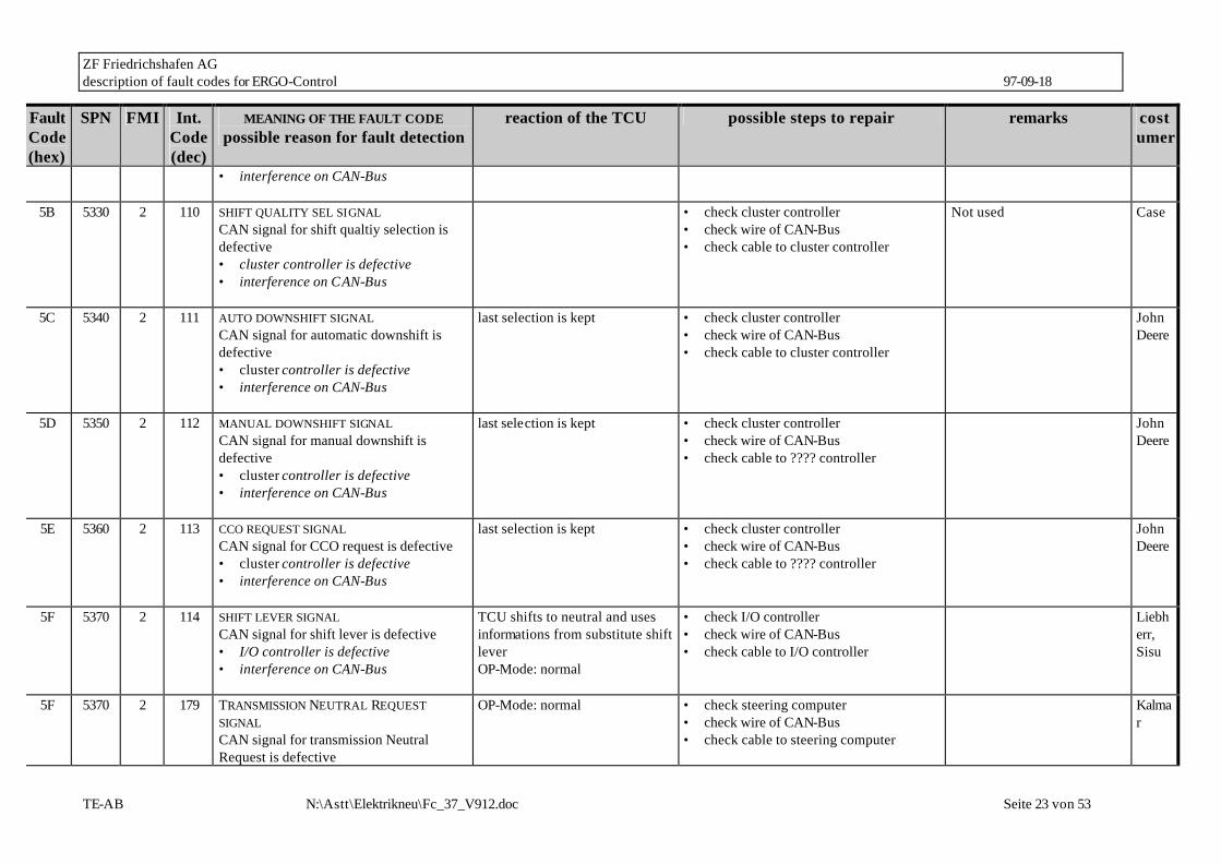
• interference on CAN-Bus
5B 5330 2 110 SHIFT QUALITY SEL SIGNAL CAN signal for shift qualtiy selection is defective • cluster controller is defective • interference on CAN-Bus
• check cluster controller • check wire of CAN-Bus • check cable to cluster controller
Not used Case
5C 5340 2 111 AUTO DOWNSHIFT SIGNAL CAN signal for automatic downshift is defective • cluster controller is defective • interference on CAN-Bus
last selection is kept • check cluster controller • check wire of CAN-Bus • check cable to cluster controller
John Deere
5D 5350 2 112 MANUAL DOWNSHIFT SIGNAL CAN signal for manual downshift is defective • cluster controller is defective • interference on CAN-Bus
last selection is kept • check cluster controller • check wire of CAN-Bus • check cable to ???? controller
John Deere
5E 5360 2 113 CCO REQUEST SIGNAL CAN signal for CCO request is defective • cluster controller is defective • interference on CAN-Bus
last selection is kept • check cluster controller • check wire of CAN-Bus • check cable to ???? controller
John Deere
5F 5370 2 114 SHIFT LEVER SIGNAL CAN signal for shift lever is defective • I/O controller is defective • interference on CAN-Bus
TCU shifts to neutral and uses informations from substitute shift lever OP-Mode: normal
• check I/O controller • check wire of CAN-Bus • check cable to I/O controller
Liebherr, Sisu
5F 5370 2 179 TRANSMISSION NEUTRAL REQUEST SIGNAL CAN signal for transmission Neutral Request is defective
OP-Mode: normal • check steering computer • check wire of CAN-Bus • check cable to steering computer
Kalmar

ZF Friedrichshafen AG description of fault codes for ERGO-Control 97-09-18
TE-AB N:\Astt\Elektrikneu\Fc_37_V912.doc Seite 24 von 53
Fault Code (hex)
SPN FMI Int. Code (dec)
MEANING OF THE FAULT CODE possible reason for fault detection
reaction of the TCU possible steps to repair remarks costumer
• steering computer is defective • interference on CAN-Bus
5F 5370 2 179 CAN MESSAGE ‘ FRONT WHEEL DRIVE STATUS (V_IDENT_FWD)’ CONTAINS INVALID DATA
TCU shifts to neutral • check FWD controller O&K
60 5380 2 115 ADDITIONAL BRAKE STATUS SIGNAL CAN signal for additional park brake status is defective • I/O controller is defective • interference on CAN-Bus
no reaction OP-Mode: normal
• check I/O controller • check wire of CAN-Bus • check cable to I/O controller
Liebherr
61 5390 2 116 AEB REQUEST SIGNAL CAN signal for AEB request is defective • I/O controller is defective • interference on CAN-Bus
no reaction OP-Mode: normal Last selection is kept
• check I/O controller • check wire of CAN-Bus • check cable to I/O controller
Liebherr, Sisu, John Deere
62 5400 2 117 PTO TORQUE SIGNAL CAN signal for PTO torque is defective • I/O controller is defective • interference on CAN-Bus
no reaction, TCU uses default PTO torque signal OP-Mode: normal
• check I/O controller • check wire of CAN-Bus • check cable to I/O controller
Liebherr
63 5410 2 118 DRIVING MODE SIGNAL CAN signal for driving mode is defective • I/O controller is defective • interference on CAN-Bus
no reaction, TCU uses default driving mode signal OP-Mode: normal
• check I/O controller • check wire of CAN-Bus • check cable to I/O controller
Liebherr
64 5420 2 119 STARTING GEAR SIGNAL CAN signal for starting gear is defective • I/O controller is defective
(illegal starting gear) • interference on CAN-Bus
no reaction, TCU uses default starting gear OP-Mode: normal
• check I/O controller • check wire of CAN-Bus • check cable to I/O controller
Liebherr
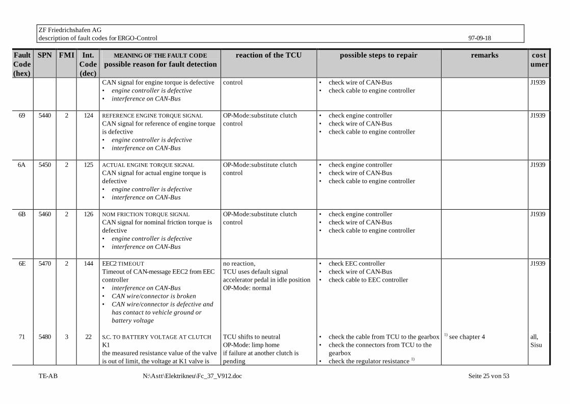
65 5430 2 120 ENGINGE TORQUE SIGNAL OP-Mode:substitute clutch • check engine controller IES,
ZF Friedrichshafen AG description of fault codes for ERGO-Control 97-09-18
TE-AB N:\Astt\Elektrikneu\Fc_37_V912.doc Seite 25 von 53
Fault Code (hex)
SPN FMI Int. Code (dec)
MEANING OF THE FAULT CODE possible reason for fault detection
reaction of the TCU possible steps to repair remarks costumer
CAN signal for engine torque is defective • engine controller is defective • interference on CAN-Bus
control • check wire of CAN-Bus • check cable to engine controller
J1939
69 5440 2 124 REFERENCE ENGINE TORQUE SIGNAL CAN signal for reference of engine torque is defective • engine controller is defective • interference on CAN-Bus
OP-Mode:substitute clutch control
• check engine controller • check wire of CAN-Bus • check cable to engine controller
J1939
6A 5450 2 125 ACTUAL ENGINE TORQUE SIGNAL CAN signal for actual engine torque is defective • engine controller is defective • interference on CAN-Bus
OP-Mode:substitute clutch control
• check engine controller • check wire of CAN-Bus • check cable to engine controller
J1939
6B 5460 2 126 NOM FRICTION TORQUE SIGNAL CAN signal for nominal friction torque is defective • engine controller is defective • interference on CAN-Bus
OP-Mode:substitute clutch control
• check engine controller • check wire of CAN-Bus • check cable to engine controller
J1939
6E 5470 2 144 EEC2 TIMEOUT Timeout of CAN-message EEC2 from EEC controller • interference on CAN-Bus • CAN wire/connector is broken • CAN wire/connector is defective and
has contact to vehicle ground or battery voltage
no reaction, TCU uses default signal accelerator pedal in idle position OP-Mode: normal
• check EEC controller • check wire of CAN-Bus • check cable to EEC controller
J1939
71 5480 3 22 S.C. TO BATTERY VOLTAGE AT CLUTCH K1 the measured resistance value of the valve is out of limit, the voltage at K1 valve is
TCU shifts to neutral OP-Mode: limp home if failure at another clutch is pending
• check the cable from TCU to the gearbox • check the connectors from TCU to the
gearbox • check the regulator resistance 1)
1) see chapter 4 all, Sisu

ZF Friedrichshafen AG description of fault codes for ERGO-Control 97-09-18
TE-AB N:\Astt\Elektrikneu\Fc_37_V912.doc Seite 26 von 53
Fault Code (hex)
SPN FMI Int. Code (dec)
MEANING OF THE FAULT CODE possible reason for fault detection
reaction of the TCU possible steps to repair remarks costumer
too high. • cable / connector is defective and has
contact to battery voltage • regulator has an internal defect
TCU shifts to neutral OP-Mode: TCU shutdown
• check internal wire harness of the gearbox
72 5480 4 10 S.C. TO GROUND AT CLUTCH K1 the measured resistance value of the valve is out of limit, the voltage at K1 valve is too low. • cable / connector is defective and has
contact to vehicle ground • cable / connector is defective and has
contact to another regulator output of the TCU
• regulator has an internal defect
TCU shifts to neutral OP-Mode: limp home if failure at another clutch is pending TCU shifts to neutral OP-Mode: TCU shutdown
• check the cable from TCU to the gearbox • check the connectors from gearbox to
TCU • check the regulator resistance 1) • check internal wire harness of the
gearbox
1) see chapter 4 all, Sisu
73 5480 5 16 O.C. AT CLUTCH K1 the measured resistance value of the valve is out of limit. • cable / connector is defective and has
no contact to TCU • regulator has an internal defect
TCU shifts to neutral OP-Mode: limp home if failure at another clutch is pending TCU shifts to neutral OP-Mode: TCU shutdown
• check the cable from TCU to the gearbox • check the connectors from gearbox to
TCU • check the regulator resistance 1) • check internal wire harness of the
gearbox
1) see chapter 4 all, Sisu
74 5490 3 23 S.C. TO BATTERY VOLTAGE AT CLUTCH K2 the measured resistance value of the valve is out of limit, the voltage at K2 valve is too high. • cable / connector is defective and has
contact to battery voltage • regulator has an internal defect
TCU shifts to neutral OP-Mode: limp home if failure at another clutch is pending TCU shifts to neutral OP-Mode: TCU shutdown
• check the cable from TCU to the gearbox • check the connectors from gearbox to
TCU • check the regulator resistance 1) • check internal wire harness of the
gearbox
1) see chapter 4 all, Sisu
75 5490 4 11 S.C. TO GROUND AT CLUTCH K2 the measured resistance value of the valve is out of limit, the voltage at K2 valve is
TCU shifts to neutral OP-Mode: limp home if failure at another clutch is
• check the cable from TCU to the gearbox • check the connectors from gearbox to
TCU
1) see chapter 4 all, Sisu

ZF Friedrichshafen AG description of fault codes for ERGO-Control 97-09-18
TE-AB N:\Astt\Elektrikneu\Fc_37_V912.doc Seite 27 von 53
Fault Code (hex)
SPN FMI Int. Code (dec)
MEANING OF THE FAULT CODE possible reason for fault detection
reaction of the TCU possible steps to repair remarks costumer
too low. • cable / connector is defective and has
contact to vehicle ground • cable / connector is defective and has
contact to another regulator output of the TCU
• regulator has an internal defect
pending TCU shifts to neutral OP-Mode: TCU shutdown
• check the regulator resistance 1) • check internal wire harness of the
gearbox
76 5490 5 17 O.C. AT CLUTCH K2 the measured resistance value of the valve is out of limit. • cable / connector is defective and has
no contact to TCU • regulator has an internal defect
TCU shifts to neutral OP-Mode: limp home if failure at another clutch is pending TCU shifts to neutral OP-Mode: TCU shutdown
• check the cable from TCU to the gearbox • check the connectors from gearbox to
TCU • check the regulator resistance 1) • check internal wire harness of the
gearbox
1) see chapter 4 all, Sisu
77 5500 3 24 S.C. TO BATTERY VOLTAGE AT CLUTCH K3 the measured resistance value of the valve is out of limit, the voltage at K3 valve is too high. • cable / connector is defective and has
contact to battery voltage • regulator has an internal defect
TCU shifts to neutral OP-Mode: limp home if failure at another clutch is pending TCU shifts to neutral OP-Mode: TCU shutdown
• check the cable from TCU to the gearbox • check the connectors from gearbox to
TCU • check the regulator resistance 1) • check internal wire harness of the
gearbox
1) see chapter 4 all, Sisu
78 5500 4 12 S.C. TO GROUND AT CLUTCH K3 the measured resistance value of the valve is out of limit, the voltage at K3 valve is too low. • cable / connector is defective and has
contact to vehicle ground • cable / connector is defective and has
contact to another regulator output of the TCU
• regulator has an internal defect
TCU shifts to neutral OP-Mode: limp home if failure at another clutch is pending TCU shifts to neutral OP-Mode: TCU shutdown
• check the cable from TCU to the gearbox • check the connectors from gearbox to
TCU • check the regulator resistance 1) • check internal wire harness of the
gearbox
1) see chapter 4 all, Sisu

ZF Friedrichshafen AG description of fault codes for ERGO-Control 97-09-18
TE-AB N:\Astt\Elektrikneu\Fc_37_V912.doc Seite 28 von 53
Fault Code (hex)
SPN FMI Int. Code (dec)
MEANING OF THE FAULT CODE possible reason for fault detection
reaction of the TCU possible steps to repair remarks costumer
79 5500 5 18 O.C. AT CLUTCH K3 the measured resistance value of the valve is out of limit. • cable / connector is defective and has
no contact to TCU • regulator has an internal defect
TCU shifts to neutral OP-Mode: limp home if failure at another clutch is pending TCU shifts to neutral OP-Mode: TCU shutdown
• check the cable from TCU to the gearbox • check the connectors from gearbox to
TCU • check the regulator resistance 1) • check internal wire harness of the
gearbox
1) see chapter 4 all, Sisu
7A 5540 3 78 S.C. TO BATTERY VOLTAGE AT CONVERTER CLUTCH
- - not used
7B 5540 4 79 S.C. TO GROUND AT CONVERTER CLUTCH
- - not used
7C 5540 5 80 O.C. AT CONVERTER CLUTCH
- - not used
7D 5550 4 166 S.C. TO GROUND AT ENGINE DERATING DEVICE • cable is defective and is contacted to
vehicle ground • engine derating device has an
internal defect • connector pin is contacted to vehicle
ground
engine derating will be on until TCU power down even if fault vanishes (loose connection) OP-Mode: normal
• check the cable from TCU to the engine derating device
• check the connectors from engine derating device to TCU
• check the resistance 1) of engine derating device
1) see chapter 4 SHI Proto T10
7E 5550 3 168 S.C. TO BATTERY VOLTAGE AT ENGINE DERATING DEVICE • cable / connector is defective and is
contacted to battery voltage • engine derating device has an
internal defect
no reaction OP-Mode: normal
• check the cable from TCU to the engine derating device
• check the connectors from backup alarm device to TCU
• check the resistance 1) of backup alarm device
SHI Proto T10
7F 5550 5 167 O.C. AT ENGINE DERATING DEVICE TCU detected a wrong voltage at the output pin, that looks like a o.c. for this output pin
no reaction OP-Mode: normal
• check the cable from TCU to the engine derating device
• check the connectors from engine derating device to TCU
1) see chapter 4 SHI Proto T10

ZF Friedrichshafen AG description of fault codes for ERGO-Control 97-09-18
TE-AB N:\Astt\Elektrikneu\Fc_37_V912.doc Seite 29 von 53
Fault Code (hex)
SPN FMI Int. Code (dec)
MEANING OF THE FAULT CODE possible reason for fault detection
reaction of the TCU possible steps to repair remarks costumer
• cable is defective and has no connection to TCU
• engine derating device has an internal defect
• connector has no connection to TCU
• check the resistance 1) of engine derating device
81 5510 3 25 S.C. TO BATTERY VOLTAGE AT CLUTCH K4 the measured resistance value of the valve is out of limit, the voltage at K4 valve is too high. • cable / connector is defective and has
contact to battery voltage • regulator has an internal defect
TCU shifts to neutral OP-Mode: limp home if failure at another clutch is pending TCU shifts to neutral OP-Mode: TCU shutdown
• check the cable from TCU to the gearbox • check the connectors from gearbox to
TCU • check the regulator resistance 1) • check internal wire harness of the
gearbox
1) see chapter 4 all
82 5510 4 13 S.C. TO GROUND AT CLUTCH K4 the measured resistance value of the valve is out of limit, the voltage at K4 valve is too low. • cable / connector is defective and has
contact to vehicle ground • cable / connector is defective and has
contact to another regulator output of the TCU
• regulator has an internal defect
TCU shifts to neutral OP-Mode: limp home if failure at another clutch is pending TCU shifts to neutral OP-Mode: TCU shutdown
• check the cable from TCU to the gearbox • check the connectors from gearbox to
TCU • check the regulator resistance 1) • check internal wire harness of the
gearbox
1) see chapter 4 all
83 5510 5 19 O.C. AT CLUTCH K4 the measured resistance value of the valve is out of limit. • cable / connector is defective and has
no contact to TCU • regulator has an internal defect
TCU shifts to neutral OP-Mode: limp home if failure at another clutch is pending TCU shifts to neutral OP-Mode: TCU shutdown
• check the cable from TCU to the gearbox • check the connectors from gearbox to
TCU • check the regulator resistance 1) • check internal wire harness of the
gearbox
1) see chapter 4 all
84 5520 3 26 S.C. TO BATTERY VOLTAGE AT CLUTCH KV
TCU shifts to neutral OP-Mode: limp home
• check the cable from TCU to the gearbox • check the connectors from gearbox to
1) see chapter 4 all, Sisu

ZF Friedrichshafen AG description of fault codes for ERGO-Control 97-09-18
TE-AB N:\Astt\Elektrikneu\Fc_37_V912.doc Seite 30 von 53
Fault Code (hex)
SPN FMI Int. Code (dec)
MEANING OF THE FAULT CODE possible reason for fault detection
reaction of the TCU possible steps to repair remarks costumer
the measured resistance value of the valve is out of limit, the voltage at KV valve is too high. • cable / connector is defective and has
contact to battery voltage • regulator has an internal defect
if failure at another clutch is pending TCU shifts to neutral OP-Mode: TCU shutdown
TCU • check the regulator resistance 1) • check internal wire harness of the
gearbox
85 5520 4 14 S.C. TO GROUND AT CLUTCH KV the measured resistance value of the valve is out of limit, the voltage at KV valve is too low. • cable / connector is defective and has
contact to vehicle ground • cable / connector is defective and has
contact to another regulator output of the TCU
• regulator has an internal defect
TCU shifts to neutral OP-Mode: limp home if failure at another clutch is pending TCU shifts to neutral OP-Mode: TCU shutdown
• check the cable from TCU to the gearbox • check the connectors from gearbox to
TCU • check the regulator resistance 1) • check internal wire harness of the
gearbox
1) see chapter 4 all, Sisu
86 5520 5 20 O.C. AT CLUTCH KV the measured resistance value of the valve is out of limit. • cable / connector is defective and has
no contact to TCU • regulator has an internal defect
TCU shifts to neutral OP-Mode: limp home if failure at another clutch is pending TCU shifts to neutral OP-Mode: TCU shutdown
• check the cable from TCU to the gearbox • check the connectors from gearbox to
TCU • check the regulator resistance 1) • check internal wire harness of the
gearbox
1) see chapter 4 all, Sisu
87 5530 3 27 S.C. TO BATTERY VOLTAGE AT CLUTCH KR the measured resistance value of the valve is out of limit, the voltage at KR valve is too high. • cable / connector is defective and has
contact to battery voltage • regulator has an internal defect
TCU shifts to neutral OP-Mode: limp home if failure at another clutch is pending TCU shifts to neutral OP-Mode: TCU shutdown
• check the cable from TCU to the gearbox • check the connectors from gearbox to
TCU • check the regulator resistance 1) • check internal wire harness of the
gearbox
1) see chapter 4 all, Sisu

ZF Friedrichshafen AG description of fault codes for ERGO-Control 97-09-18
TE-AB N:\Astt\Elektrikneu\Fc_37_V912.doc Seite 31 von 53
Fault Code (hex)
SPN FMI Int. Code (dec)
MEANING OF THE FAULT CODE possible reason for fault detection
reaction of the TCU possible steps to repair remarks costumer
88 5530 4 15 S.C. TO GROUND AT CLUTCH KR the measured resistance value of the valve is out of limit, the voltage at KR valve is too low. • cable / connector is defective and has
contact to vehicle ground • cable / connector is defective and has
contact to another regulator output of the TCU
• regulator has an internal defect
TCU shifts to neutral OP-Mode: limp home if failure at another clutch is pending TCU shifts to neutral OP-Mode: TCU shutdown
• check the cable from TCU to the gearbox • check the connectors from gearbox to
TCU • check the regulator resistance 1) • check internal wire harness of the
gearbox
1) see chapter 4 all, Sisu
89 5530 5 21 O.C. AT CLUTCH KR the measured resistance value of the valve is out of limit. • cable / connector is defective and has
no contact to TCU • regulator has an internal defect
TCU shifts to neutral OP-Mode: limp home if failure at another clutch is pending TCU shifts to neutral OP-Mode: TCU shutdown
• check the cable from TCU to the gearbox • check the connectors from gearbox to
TCU • check the regulator resistance 1) • check internal wire harness of the
gearbox
1) see chapter 4 all, Sisu
91 5560 4 1 S.C. TO GROUND AT RELAY REVERSE WARNING ALARM TCU detected a wrong voltage at the output pin, that looks like a s.c. to vehicle ground • cable is defective and is contacted to
vehicle ground • backup alarm device has an internal
defect • connector pin is contacted to vehicle
ground
backup alarm will be on until TCU power down even if fault vanishes (loose connection) OP-Mode: normal
• check the cable from TCU to the backup alarm device
• check the connectors from backup alarm device to TCU
• check the resistance 1) of backup alarm device
1) see chapter 4 all
92 5560 3 3 S.C. TO BATTERY VOLTAGE AT RELAY REVERSE WARNING ALARM TCU detected a wrong voltage at the output pin, that looks like a s.c. to battery
no reaction OP-Mode: normal
• check the cable from TCU to the backup alarm device
• check the connectors from backup alarm device to TCU
1) see chapter 4 all

ZF Friedrichshafen AG description of fault codes for ERGO-Control 97-09-18
TE-AB N:\Astt\Elektrikneu\Fc_37_V912.doc Seite 32 von 53
Fault Code (hex)
SPN FMI Int. Code (dec)
MEANING OF THE FAULT CODE possible reason for fault detection
reaction of the TCU possible steps to repair remarks costumer
voltage • cable is defective and is contacted to
battery voltage • backup alarm device has an internal
defect • connector pin is contacted to battery
voltage
• check the resistance 1) of backup alarm device
93 5560 5 2 O.C. AT RELAY REVERSE WARNING ALARM TCU detected a wrong voltage at the output pin, that looks like a o.c. for this output pin • cable is defective and has no
connection to TCU • backup alarm device has an internal
defect • connector has no connection to TCU
no reaction OP-Mode: normal
• check the cable from TCU to the backup alarm device
• check the connectors from backup alarm device to TCU
• check the resistance 1) of backup alarm device
1) see chapter 4 all
94 5570 4 4 S.C. TO GROUND AT RELAY STARTER INTERLOCK TCU detected a wrong voltage at the output pin, that looks like a s.c. to vehicle ground • cable is defective and is contacted to
vehicle ground • starter interlock relay has an internal
defect • connector pin is contacted to vehicle
ground
no reaction OP-Mode: normal
• check the cable from TCU to the starter interlock relay
• check the connectors from starter interlock relay to TCU
• check the resistance 1) of starter interlock relay
1) see chapter 4
95 5570 3 6 S.C. TO BATTERY VOLTAGE AT RELAY STARTER INTERLOCK TCU detected a wrong voltage at the output pin, that looks like a s.c. to battery voltage
no reaction OP-Mode: normal
• check the cable from TCU to the starter interlock relay
• check the connectors from starter interlock relay to TCU
• check the resistance 1) of starter
1) see chapter 4

ZF Friedrichshafen AG description of fault codes for ERGO-Control 97-09-18
TE-AB N:\Astt\Elektrikneu\Fc_37_V912.doc Seite 33 von 53
Fault Code (hex)
SPN FMI Int. Code (dec)
MEANING OF THE FAULT CODE possible reason for fault detection
reaction of the TCU possible steps to repair remarks costumer
• cable is defective and is contacted to battery voltage
• starter interlock relay has an internal defect
• connector pin is contacted to battery voltage
interlock relay
96 5570 5 5 O.C. AT RELAY STARTER INTERLOCK TCU detected a wrong voltage at the output pin, that looks like a o.c. for this output pin • cable is defective and has no
connection to TCU • starter interlock relay has an internal
defect • connector has no connection to TCU
no reaction OP-Mode: normal
• check the cable from TCU to the starter interlock relay
• check the connectors from starter interlock relay to TCU
• check the resistance 1) of starter interlock relay
1) see chapter 4
97 5580 4 7 S.C. TO GROUND AT PARK BRAKE SOLENOID TCU detected a wrong voltage at the output pin, that looks like a s.c. to vehicle ground • cable is defective and is contacted to
vehicle ground • park brake solenoid has an internal
defect • connector pin is contacted to vehicle
ground
no reaction OP-Mode: normal
• check the cable from TCU to the park brake solenoid
• check the connectors from park brake solenoid to TCU
• check the resistance 1) of park brake solenoid
1) see chapter 4 John Deere
98 5580 3 9 S.C. TO BATTERY VOLTAGE AT PARK BRAKE SOLENOID TCU detected a wrong voltage at the output pin, that looks like a s.c. to battery voltage • cable is defective and is contacted to
no reaction optional: (some customers) TCU shifts to neutral caused by park brake feed back OP-Mode: normal
• check the cable from TCU to the park brake solenoid
• check the connectors from park brake solenoid to TCU
• check the resistance 1) of park brake solenoid
1) see chapter 4 John Deere

ZF Friedrichshafen AG description of fault codes for ERGO-Control 97-09-18
TE-AB N:\Astt\Elektrikneu\Fc_37_V912.doc Seite 34 von 53
Fault Code (hex)
SPN FMI Int. Code (dec)
MEANING OF THE FAULT CODE possible reason for fault detection
reaction of the TCU possible steps to repair remarks costumer
battery voltage • park brake solenoid has an internal
defect • connector pin is contacted to battery
voltage
99 5580 5 8 O.C. AT PARK BRAKE SOLENOID TCU detected a wrong voltage at the output pin, that looks like a o.c. for this output pin • cable is defective and has no
connection to TCU • park brake solenoid has an internal
defect • connector has no connection to TCU
no reaction optional: (some customers) TCU shifts to neutral caused by park brake feed back OP-Mode: normal
• check the cable from TCU to the park brake solenoid
• check the connectors from park brake solenoid to TCU
• check the resistance 1) of park brake solenoid
1) see chapter 4 John Deere
9A 5590 4 66 S.C. TO GROUND AT CONVERTER LOCK UP CLUTCH SOLENOID TCU detected a wrong voltage at the output pin, that looks like a s.c. to vehicle ground • cable is defective and is contacted to
vehicle ground • converter clutch solenoid has an
internal defect • connector pin is contacted to vehicle
ground
no reaction OP-mode: normal
• check the cable from TCU to the converter clutch solenoid
• check the connectors from converter clutch solenoid to TCU
• check the resistance 1) of converter clutch solenoid
1) see chapter 4 6WG
9B 5590 3 67 O.C. AT CONVERTER LOCK UP CLUTCH SOLENOID TCU detected a wrong voltage at the output pin, that looks like a o.c. for this output pin • cable is defective and has no
connection to TCU
converter clutch always open, retarder not available OP-mode: normal
• check the cable from TCU to the converter clutch solenoid
• check the connectors from converter clutch solenoid to TCU
• check the resistance 1) of converter clutch solenoid
1) see chapter 4 6WG
ZF Friedrichshafen AG description of fault codes for ERGO-Control 97-09-18
TE-AB N:\Astt\Elektrikneu\Fc_37_V912.doc Seite 35 von 53
Fault Code (hex)
SPN FMI Int. Code (dec)
MEANING OF THE FAULT CODE possible reason for fault detection
reaction of the TCU possible steps to repair remarks costumer
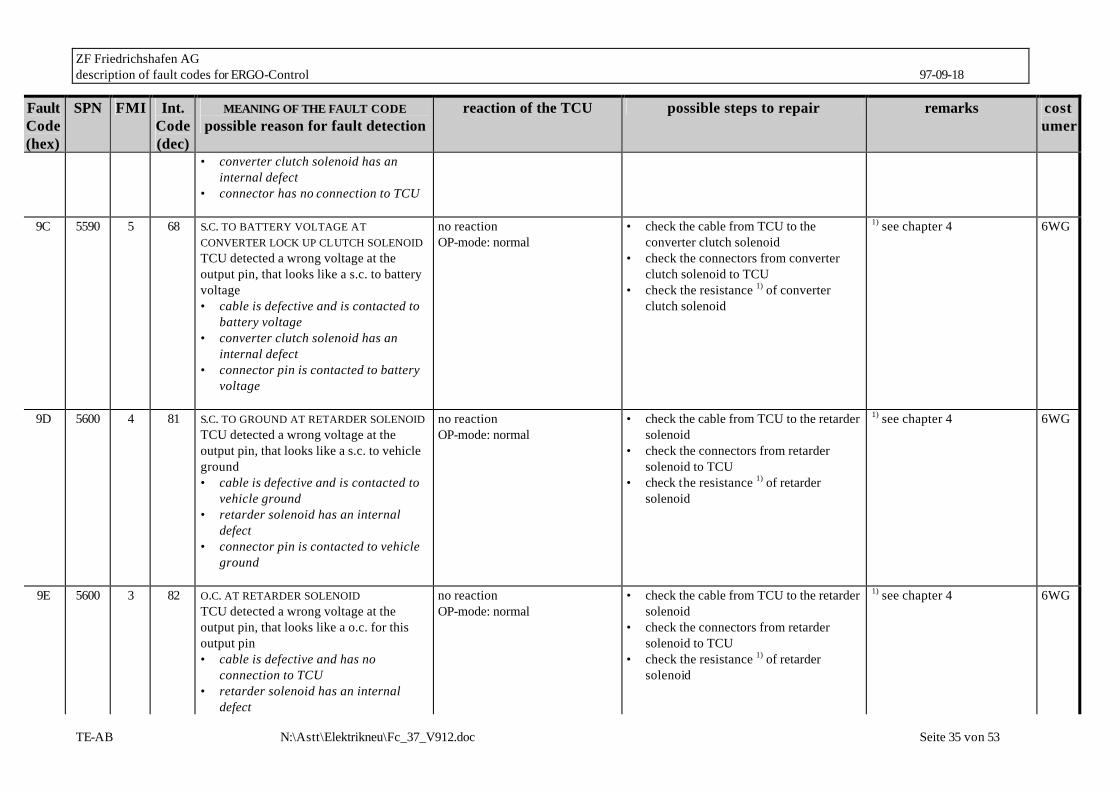
• converter clutch solenoid has an internal defect
• connector has no connection to TCU
9C 5590 5 68 S.C. TO BATTERY VOLTAGE AT CONVERTER LOCK UP CLUTCH SOLENOID TCU detected a wrong voltage at the output pin, that looks like a s.c. to battery voltage • cable is defective and is contacted to
battery voltage • converter clutch solenoid has an
internal defect • connector pin is contacted to battery
voltage
no reaction OP-mode: normal
• check the cable from TCU to the converter clutch solenoid
• check the connectors from converter clutch solenoid to TCU
• check the resistance 1) of converter clutch solenoid
1) see chapter 4 6WG
9D 5600 4 81 S.C. TO GROUND AT RETARDER SOLENOID TCU detected a wrong voltage at the output pin, that looks like a s.c. to vehicle ground • cable is defective and is contacted to
vehicle ground • retarder solenoid has an internal
defect • connector pin is contacted to vehicle
ground
no reaction OP-mode: normal
• check the cable from TCU to the retarder solenoid
• check the connectors from retarder solenoid to TCU
• check the resistance 1) of retarder solenoid
1) see chapter 4 6WG
9E 5600 3 82 O.C. AT RETARDER SOLENOID TCU detected a wrong voltage at the output pin, that looks like a o.c. for this output pin • cable is defective and has no
connection to TCU • retarder solenoid has an internal
defect
no reaction OP-mode: normal
• check the cable from TCU to the retarder solenoid
• check the connectors from retarder solenoid to TCU
• check the resistance 1) of retarder solenoid
1) see chapter 4 6WG

ZF Friedrichshafen AG description of fault codes for ERGO-Control 97-09-18
TE-AB N:\Astt\Elektrikneu\Fc_37_V912.doc Seite 36 von 53
Fault Code (hex)
SPN FMI Int. Code (dec)
MEANING OF THE FAULT CODE possible reason for fault detection
reaction of the TCU possible steps to repair remarks costumer
• connector has no connection to TCU
9F 5600 5 83 S.C. TO BATTERY VOLTAGE AT RETARDER SOLENOID TCU detected a wrong voltage at the output pin, that looks like a s.c. to battery voltage • cable is defective and is contacted to
battery voltage • retarder solenoid has an internal
defect • connector pin is contacted to battery
voltage
no reaction OP-mode: normal
• check the cable from TCU to the retarder solenoid
• check the connectors from retarder solenoid to TCU
• check the resistance 1) of retarder solenoid
1) see chapter 4 6WG
A1 5610 4 84 S.C. TO GROUND AT DIFFLOCK OR AXLE CONNECTION SOLENOID TCU detected a wrong voltage at the output pin, that looks like a s.c. to vehicle ground • cable is defective and is contacted to
vehicle ground • difflock solenoid has an internal
defect • connector pin is contacted to vehicle
ground
no reaction OP-mode: normal
• check the cable from TCU to the difflock solenoid
• check the connectors from difflock solenoid to TCU
• check the resistance 1) of difflock solenoid
1) see chapter 4 6WG
A2 5610 3 85 S.C. TO BATTERY VOLTAGE AT DIFFLOCK OR AXLE CONNECTION SOLENOID TCU detected a wrong voltage at the output pin, that looks like a s.c. to battery voltage • cable is defective and is contacted to
battery voltage • difflock solenoid has an internal
no reaction OP-mode: normal
• check the cable from TCU to the difflock solenoid
• check the connectors from difflock solenoid to TCU
• check the resistance 1) of difflock solenoid
1) see chapter 4 6WG

ZF Friedrichshafen AG description of fault codes for ERGO-Control 97-09-18
TE-AB N:\Astt\Elektrikneu\Fc_37_V912.doc Seite 37 von 53
Fault Code (hex)
SPN FMI Int. Code (dec)
MEANING OF THE FAULT CODE possible reason for fault detection
reaction of the TCU possible steps to repair remarks costumer
defect • connector pin is contacted to battery
voltage
A3 5610 5 86 O.C. AT DIFFLOCK OR AXLE CONNECTION SOLENOID TCU detected a wrong voltage at the output pin, that looks like a o.c. for this output pin • cable is defective and has no
connection to TCU • difflock solenoid has an internal
defect • connector has no connection to TCU
no reaction OP-mode: normal
• check the cable from TCU to the difflock solenoid
• check the connectors from difflock solenoid to TCU
• check the resistance 1) of difflock solenoid
1) see chapter 4 6WG
A4 5620 4 96 S.C. TO GROUND AT WARNING SIGNAL OUTPUT TCU detected a wrong voltage at the output pin, that looks like a s.c. to vehicle ground • cable is defective and is contacted to
vehicle ground • warning device has an internal defect • connector pin is contacted to vehicle
ground
no reaction OP-mode: normal
• check the cable from TCU to the warning device
• check the connectors from warning device to TCU
• check the resistance 1) of warning device
1) see chapter 4 6WG
A5 5620 5 97 O.C. AT WARNING SIGNAL OUTPUT TCU detected a wrong voltage at the output pin, that looks like a o.c. for this output pin • cable is defective and has no
connection to TCU • warning device has an internal defect • connector has no connection to TCU
no reaction OP-mode: normal
• check the cable from TCU to the warning device
• check the connectors from warning device to TCU
• check the resistance 1) of warning device
1) see chapter 4 6WG

ZF Friedrichshafen AG description of fault codes for ERGO-Control 97-09-18
TE-AB N:\Astt\Elektrikneu\Fc_37_V912.doc Seite 38 von 53
Fault Code (hex)
SPN FMI Int. Code (dec)
MEANING OF THE FAULT CODE possible reason for fault detection
reaction of the TCU possible steps to repair remarks costumer
A6 5620 3 98 S.C. TO BATTERY VOLTAGE AT WARNING SIGNAL OUTPUT TCU detected a wrong voltage at the output pin, that looks like a s.c. to battery voltage • cable is defective and is contacted to
battery voltage • warning device has an internal defect • connector pin is contacted to battery
voltage
no reaction OP-mode: normal
• check the cable from TCU to the warning device
• check the connectors from warning device to TCU
• check the resistance 1) of warning device
1) see chapter 4 6WG
A7 5630 4 157 S.C. TO GROUND AT CUSTOMER SPECIFIC FUNCTION NO. 4 TCU detected a wrong voltage at the output pin, that looks like a s.c. to vehicle ground • cable is defective and is contacted to
vehicle ground • customer specific function no. 4 device
has an internal defect • connector pin is contacted to vehicle
ground
customer specific • check the cable from TCU to customer specific function no. 4 device
• check the connectors from customer specific function no. 4 device to TCU
• check the resistance of customer specific function no. 4 device
1) see chapter 4 Z-Funktion4
A8 5630 3 159 S.C. TO BATTERY VOLTAGE AT CUSTOMER SPECIFIC FUNCTION NO. 4 TCU detected a wrong voltage at the output pin, that looks like a s.c. to battery voltage • cable is defective and is contacted to
battery voltage • customer specific function no. 4 device
has an internal defect • connector pin is contacted to battery
voltage
customer specific • check the cable from TCU to customer specific function no. 4 device
• check the connectors from customer specific function no. 4 device to TCU
• check the resistance of customer specific function no. 4 device
1) see chapter 4 Z-Funktion4

ZF Friedrichshafen AG description of fault codes for ERGO-Control 97-09-18
TE-AB N:\Astt\Elektrikneu\Fc_37_V912.doc Seite 39 von 53
Fault Code (hex)
SPN FMI Int. Code (dec)
MEANING OF THE FAULT CODE possible reason for fault detection
reaction of the TCU possible steps to repair remarks costumer
A9 5630 5 158 O.C. AT CUSTOMER SPECIFIC FUNCTION NO. 4 TCU detected a wrong voltage at the output pin, that looks like a o.c. for this output pin • cable is defective and has no
connection to TCU • customer specific function no. 4 device
has an internal defect • connector has no connection to TCU
customer specific • check the cable from TCU to customer specific function no. 4 device
• check the connectors from customer specific function no. 4 device to TCU
• check the resistance of customer specific function no. 4 device
1) see chapter 4 Z-Funktion4
AA 5640 4 160 S.C. TO GROUND AT CUSTOMER SPECIFIC FUNCTION NO. 5 TCU detected a wrong voltage at the output pin, that looks like a s.c. to vehicle ground • cable is defective and is contacted to
vehicle ground • customer specific function no. 5 device
has an internal defect • connector pin is contacted to vehicle
ground
customer specific • check the cable from TCU to customer specific function no. 5 device
• check the connectors from customer specific function no. 5 device to TCU
• check the resistance of customer specific function no. 5 device
1) see chapter 4 Z-Funktion5
AB 5640 3 162 S.C. TO BATTERY VOLTAGE AT CUSTOMER SPECIFIC FUNCTION NO. 5 TCU detected a wrong voltage at the output pin, that looks like a s.c. to battery voltage • cable is defective and is contacted to
battery voltage • customer specific function no. 5 device
has an internal defect • connector pin is contacted to battery
voltage
customer specific • check the cable from TCU to customer specific function no. 5 device
• check the connectors from customer specific function no. 5 device to TCU
• check the resistance of customer specific function no. 5 device
1) see chapter 4 Z-Funktion5

ZF Friedrichshafen AG description of fault codes for ERGO-Control 97-09-18
TE-AB N:\Astt\Elektrikneu\Fc_37_V912.doc Seite 40 von 53
Fault Code (hex)
SPN FMI Int. Code (dec)
MEANING OF THE FAULT CODE possible reason for fault detection
reaction of the TCU possible steps to repair remarks costumer
AC 5640 5 161 O.C. AT CUSTOMER SPECIFIC FUNCTION NO. 5 TCU detected a wrong voltage at the output pin, that looks like a o.c. for this output pin • cable is defective and has no
connection to TCU • customer specific function no. 5 device
has an internal defect • connector has no connection to TCU
customer specific • check the cable from TCU to customer specific function no. 5 device
• check the connectors from customer specific function no. 5 device to TCU
• check the resistance of customer specific function no. 5 device
1) see chapter 4 Z-Funktion5
AD 5650 4 163 S.C. TO GROUND AT CUSTOMER SPECIFIC FUNCTION NO. 6 TCU detected a wrong voltage at the output pin, that looks like a s.c. to vehicle ground • cable is defective and is contacted to
vehicle ground • customer specific function no. 6 device
has an internal defect • connector pin is contacted to vehicle
ground
customer specific • check the cable from TCU to function 6 device
• check the connectors from customer specific function no. 6 device to TCU
• check the resistance of function 6 device
1) see chapter 4 Z-Funktion6
AE 5650 3 165 S.C. TO BATTERY VOLTAGE AT CUSTOMER SPECIFIC FUNCTION NO. 6 TCU detected a wrong voltage at the output pin, that looks like a s.c. to battery voltage • cable is defective and is contacted to
battery voltage • customer specific function no. 6 device
has an internal defect • connector pin is contacted to battery
voltage
customer specific • check the cable from TCU to customer specific function no. 6 device
• check the connectors from customer specific function no. 6 device to TCU
• check the resistance of customer specific function no. 6 device
1) see chapter 4 Z-Funktion6
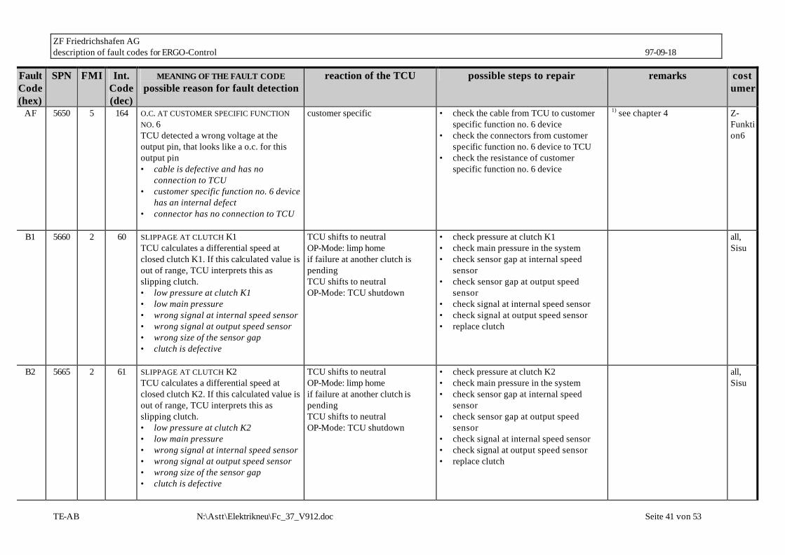
ZF Friedrichshafen AG description of fault codes for ERGO-Control 97-09-18
TE-AB N:\Astt\Elektrikneu\Fc_37_V912.doc Seite 41 von 53
Fault Code (hex)
SPN FMI Int. Code (dec)
MEANING OF THE FAULT CODE possible reason for fault detection
reaction of the TCU possible steps to repair remarks costumer
AF 5650 5 164 O.C. AT CUSTOMER SPECIFIC FUNCTION NO. 6 TCU detected a wrong voltage at the output pin, that looks like a o.c. for this output pin • cable is defective and has no
connection to TCU • customer specific function no. 6 device
has an internal defect • connector has no connection to TCU
customer specific • check the cable from TCU to customer specific function no. 6 device
• check the connectors from customer specific function no. 6 device to TCU
• check the resistance of customer specific function no. 6 device
1) see chapter 4 Z-Funktion6
B1 5660 2 60 SLIPPAGE AT CLUTCH K1 TCU calculates a differential speed at closed clutch K1. If this calculated value is out of range, TCU interprets this as slipping clutch. • low pressure at clutch K1 • low main pressure • wrong signal at internal speed sensor • wrong signal at output speed sensor • wrong size of the sensor gap • clutch is defective
TCU shifts to neutral OP-Mode: limp home if failure at another clutch is pending TCU shifts to neutral OP-Mode: TCU shutdown
• check pressure at clutch K1 • check main pressure in the system • check sensor gap at internal speed
sensor • check sensor gap at output speed
sensor • check signal at internal speed sensor • check signal at output speed sensor • replace clutch
all, Sisu
B2 5665 2 61 SLIPPAGE AT CLUTCH K2 TCU calculates a differential speed at closed clutch K2. If this calculated value is out of range, TCU interprets this as slipping clutch. • low pressure at clutch K2 • low main pressure • wrong signal at internal speed sensor • wrong signal at output speed sensor • wrong size of the sensor gap • clutch is defective
TCU shifts to neutral OP-Mode: limp home if failure at another clutch is pending TCU shifts to neutral OP-Mode: TCU shutdown
• check pressure at clutch K2 • check main pressure in the system • check sensor gap at internal speed
sensor • check sensor gap at output speed
sensor • check signal at internal speed sensor • check signal at output speed sensor • replace clutch
all, Sisu

ZF Friedrichshafen AG description of fault codes for ERGO-Control 97-09-18
TE-AB N:\Astt\Elektrikneu\Fc_37_V912.doc Seite 42 von 53
Fault Code (hex)
SPN FMI Int. Code (dec)
MEANING OF THE FAULT CODE possible reason for fault detection
reaction of the TCU possible steps to repair remarks costumer
B3 5670 2 62 SLIPPAGE AT CLUTCH K3 TCU calculates a differential speed at closed clutch K3. If this calculated value is out of range, TCU interprets this as slipping clutch. • low pressure at clutch K3 • low main pressure • wrong signal at internal speed sensor • wrong signal at output speed sensor • wrong size of the sensor gap • clutch is defective
TCU shifts to neutral OP-Mode: limp home if failure at another clutch is pending TCU shifts to neutral OP-Mode: TCU shutdown
• check pressure at clutch K3 • check main pressure in the system • check sensor gap at internal speed
sensor • check sensor gap at output speed
sensor • check signal at internal speed sensor • check signal at output speed sensor • replace clutch
all, Sisu
B4 5675 2 63 SLIPPAGE AT CLUTCH K4 TCU calculated a difference speed at TCU calculates a differential speed at closed clutch K4. If this calculated value is out of range, TCU interprets this as slipping clutch. • low pressure at clutch K4 • low main pressure • wrong signal at internal speed sensor • wrong signal at turbine speed sensor • wrong size of the sensor gap • clutch is defective
TCU shifts to neutral OP-Mode: limp home if failure at another clutch is pending TCU shifts to neutral OP-Mode: TCU shutdown
• check pressure at clutch K4 • check main pressure in the system • check sensor gap at internal speed
sensor • check sensor gap at turbine speed
sensor • check signal at internal speed sensor • check signal at turbine speed sensor • replace clutch
all
B5 5680 2 64 SLIPPAGE AT CLUTCH KV TCU calculates a differential speed at closed clutch KV. If this calculated value is out of range, TCU interprets this as slipping clutch. • low pressure at clutch KV • low main pressure • wrong signal at internal speed sensor • wrong signal at turbine speed sensor • wrong size of the sensor gap
TCU shifts to neutral OP-Mode: limp home if failure at another clutch is pending TCU shifts to neutral OP-Mode: TCU shutdown
• check pressure at clutch KV • check main pressure in the system • check sensor gap at internal speed
sensor • check sensor gap at turbine speed
sensor • check signal at internal speed sensor • check signal at turbine speed sensor • replace clutch
all, Sisu
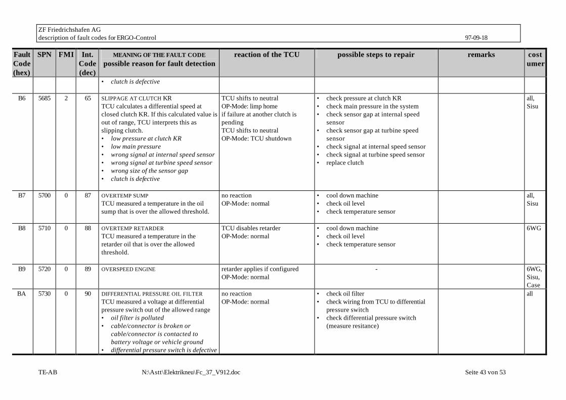
ZF Friedrichshafen AG description of fault codes for ERGO-Control 97-09-18
TE-AB N:\Astt\Elektrikneu\Fc_37_V912.doc Seite 43 von 53
Fault Code (hex)
SPN FMI Int. Code (dec)
MEANING OF THE FAULT CODE possible reason for fault detection
reaction of the TCU possible steps to repair remarks costumer
• clutch is defective
B6 5685 2 65 SLIPPAGE AT CLUTCH KR TCU calculates a differential speed at closed clutch KR. If this calculated value is out of range, TCU interprets this as slipping clutch. • low pressure at clutch KR • low main pressure • wrong signal at internal speed sensor • wrong signal at turbine speed sensor • wrong size of the sensor gap • clutch is defective
TCU shifts to neutral OP-Mode: limp home if failure at another clutch is pending TCU shifts to neutral OP-Mode: TCU shutdown
• check pressure at clutch KR • check main pressure in the system • check sensor gap at internal speed
sensor • check sensor gap at turbine speed
sensor • check signal at internal speed sensor • check signal at turbine speed sensor • replace clutch
all, Sisu
B7 5700 0 87 OVERTEMP SUMP TCU measured a temperature in the oil sump that is over the allowed threshold.
no reaction OP-Mode: normal
• cool down machine • check oil level • check temperature sensor
all, Sisu
B8 5710 0 88 OVERTEMP RETARDER TCU measured a temperature in the retarder oil that is over the allowed threshold.
TCU disables retarder OP-Mode: normal
• cool down machine • check oil level • check temperature sensor
6WG
B9 5720 0 89 OVERSPEED ENGINE
retarder applies if configured OP-Mode: normal
- 6WG, Sisu, Case
BA 5730 0 90 DIFFERENTIAL PRESSURE OIL FILTER TCU measured a voltage at differential pressure switch out of the allowed range • oil filter is polluted • cable/connector is broken or
cable/connector is contacted to battery voltage or vehicle ground
• differential pressure switch is defective
no reaction OP-Mode: normal
• check oil filter • check wiring from TCU to differential
pressure switch • check differential pressure switch
(measure resitance)
all

ZF Friedrichshafen AG description of fault codes for ERGO-Control 97-09-18
TE-AB N:\Astt\Elektrikneu\Fc_37_V912.doc Seite 44 von 53
Fault Code (hex)
SPN FMI Int. Code (dec)
MEANING OF THE FAULT CODE possible reason for fault detection
reaction of the TCU possible steps to repair remarks costumer
BB 5740 2 172 SLIPPAGE AT CONVERTER LOCKUP CLUTCH TCU calculates a differential speed at closed converter lockup clutch. If this calculated value is out of range, TCU interprets this as slipping clutch. • low pressure at converter lockup
clutch • low main pressure • wrong signal at engine speed sensor • wrong signal at turbine speed sensor • wrong size of the sensor gap • clutch is defective
• check pressure at converter lockup clutch
• check main pressure in the system • check sensor gap at engine speed
sensor • check sensor gap at turbine speed
sensor • check signal at engine speed sensor • check signal at turbine speed sensor • replace clutch
6WG
BD 5750 4 169 S.C. TO GROUND AT ENGINE BRKAE SOLENOID TCU detected a wrong voltage at the output pin, that looks like a s.c. to vehicle ground • cable is defective and is contacted to
vehicle ground • engine brake solenoid has an internal
defect • connector pin is contacted to vehicle
ground
no reaction OP-mode: normal
• check the cable from TCU to the engine brake solenoid
• check the connectors from engine brake solenoid to TCU
• check the resistance 1) of engine brake solenoid
1) see chapter 4 6WG
BE 5750 3 171 S.C. TO BATTERY VOLTAGE AT ENGINE BRAKE TCU detected a wrong voltage at the output pin, that looks like a s.c. to battery voltage • cable is defective and is contacted to
battery voltage
no reaction OP-mode: normal
• check the cable from TCU to the engine brake solenoid
• check the connectors from engine brake solenoid to TCU
• check the resistance 1) of engine brake solenoid
1) see chapter 4 6WG
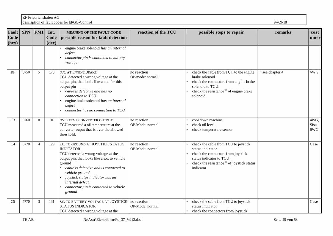
ZF Friedrichshafen AG description of fault codes for ERGO-Control 97-09-18
TE-AB N:\Astt\Elektrikneu\Fc_37_V912.doc Seite 45 von 53
Fault Code (hex)
SPN FMI Int. Code (dec)
MEANING OF THE FAULT CODE possible reason for fault detection
reaction of the TCU possible steps to repair remarks costumer
• engine brake solenoid has an internal defect
• connector pin is contacted to battery voltage
BF 5750 5 170 O.C. AT ENGINE BRAKE
TCU detected a wrong voltage at the output pin, that looks like a o.c. for this output pin • cable is defective and has no
connection to TCU • engine brake solenoid has an internal
defect • connector has no connection to TCU
no reaction OP-mode: normal
• check the cable from TCU to the engine brake solenoid
• check the connectors from engine brake solenoid to TCU
• check the resistance 1) of engine brake solenoid
1) see chapter 4 6WG
C3 5760 0 91 OVERTEMP CONVERTER OUTPUT TCU measured a oil temperature at the converter ouput that is over the allowed threshold.
no reaction OP-Mode: normal
• cool down machine • check oil level • check temperature sensor
4WG, Sisu 6WG
C4 5770 4 129 S.C. TO GROUND AT JOYSTICK STATUS INDICATOR TCU detected a wrong voltage at the output pin, that looks like a s.c. to vehicle ground • cable is defective and is contacted to
vehicle ground • joystick status indicator has an
internal defect • connector pin is contacted to vehicle
ground
no reaction OP-Mode: normal
• check the cable from TCU to joystick status indicator
• check the connectors from joystick status indicator to TCU
• check the resistance 1) of joystick status indicator
Case
C5 5770 3 131 S.C. TO BATTERY VOLTAGE AT JOYSTICK STATUS INDICATOR TCU detected a wrong voltage at the
no reaction OP-Mode: normal
• check the cable from TCU to joystick status indicator
• check the connectors from joystick
Case

ZF Friedrichshafen AG description of fault codes for ERGO-Control 97-09-18
TE-AB N:\Astt\Elektrikneu\Fc_37_V912.doc Seite 46 von 53
Fault Code (hex)
SPN FMI Int. Code (dec)
MEANING OF THE FAULT CODE possible reason for fault detection
reaction of the TCU possible steps to repair remarks costumer
output pin, that looks like a s.c. to battery voltage • cable is defective and is contacted to
battery voltage • joystick status indicator has an
internal defect • connector pin is contacted to battery
voltage
status indicator to TCU • check the resistance 1) of joystick status
indicator
C6 5770 5 130 O.C. AT JOYSTICK STATUS INDICATOR TCU detected a wrong voltage at the output pin, that looks like a o.c. for this output pin • cable is defective and has no
connection to TCU • joystick status indicator has an
internal defect • connector has no connection to TCU
no reaction OP-Mode: normal
• check the cable from TCU to joystick status indicator
• check the connectors from joystick status indicator to TCU
• check the resistance 1) of joystick status indicator
Case
C7 5780 4 132 S.C. TO GROUND AT OVERTEMP NEUTRAL INDICATOR TCU detected a wrong voltage at the output pin, that looks like a s.c. to vehicle ground • cable is defective and is contacted to
vehicle ground • overtemp status indicator has an
internal defect • connector pin is contacted to vehicle
ground
no reaction OP-Mode: normal
• check the cable from TCU to OVERTEMP NEUTRAL INDICATOR
• check the connectors from OVERTEMP NEUTRAL INDICATOR to TCU
• check the resistance 1) of OVERTEMP NEUTRAL INDICATOR
Shinsung
C8 5780 3 134 S.C. TO BATTERY VOLTAGE AT OVERTEMP NEUTRAL INDICATOR TCU detected a wrong voltage at the output pin, that looks like a s.c. to battery
no reaction OP-Mode: normal
• check the cable from TCU to OVERTEMP NEUTRAL INDICATOR
• check the connectors from OVERTEMP NEUTRAL INDICATOR to TCU
Shinsung
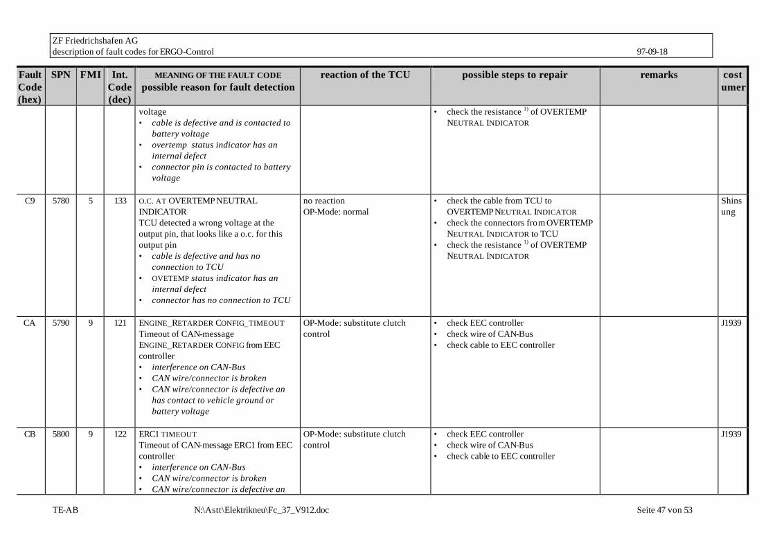
ZF Friedrichshafen AG description of fault codes for ERGO-Control 97-09-18
TE-AB N:\Astt\Elektrikneu\Fc_37_V912.doc Seite 47 von 53
Fault Code (hex)
SPN FMI Int. Code (dec)
MEANING OF THE FAULT CODE possible reason for fault detection
reaction of the TCU possible steps to repair remarks costumer
voltage • cable is defective and is contacted to
battery voltage • overtemp status indicator has an
internal defect • connector pin is contacted to battery
voltage
• check the resistance 1) of OVERTEMP NEUTRAL INDICATOR
C9 5780 5 133 O.C. AT OVERTEMP NEUTRAL INDICATOR TCU detected a wrong voltage at the output pin, that looks like a o.c. for this output pin • cable is defective and has no
connection to TCU • OVETEMP status indicator has an
internal defect • connector has no connection to TCU
no reaction OP-Mode: normal
• check the cable from TCU to OVERTEMP NEUTRAL INDICATOR
• check the connectors from OVERTEMP NEUTRAL INDICATOR to TCU
• check the resistance 1) of OVERTEMP NEUTRAL INDICATOR
Shinsung
CA 5790 9 121 ENGINE_RETARDER CONFIG_TIMEOUT Timeout of CAN-message ENGINE_RETARDER CONFIG from EEC controller • interference on CAN-Bus • CAN wire/connector is broken • CAN wire/connector is defective an
has contact to vehicle ground or battery voltage
OP-Mode: substitute clutch control
• check EEC controller • check wire of CAN-Bus • check cable to EEC controller
J1939
CB 5800 9 122 ERC1 TIMEOUT Timeout of CAN-message ERC1 from EEC controller • interference on CAN-Bus • CAN wire/connector is broken • CAN wire/connector is defective an
OP-Mode: substitute clutch control
• check EEC controller • check wire of CAN-Bus • check cable to EEC controller
J1939
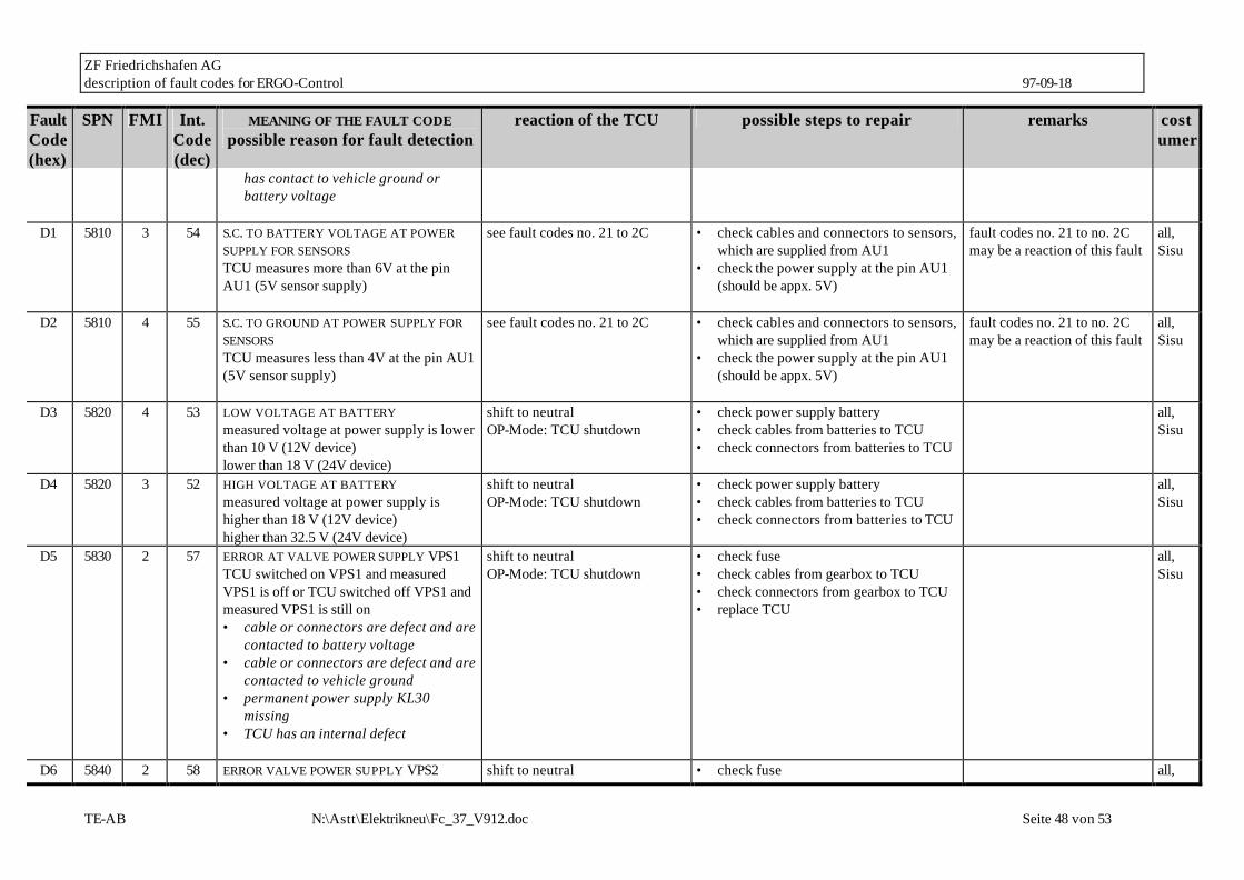
ZF Friedrichshafen AG description of fault codes for ERGO-Control 97-09-18
TE-AB N:\Astt\Elektrikneu\Fc_37_V912.doc Seite 48 von 53
Fault Code (hex)
SPN FMI Int. Code (dec)
MEANING OF THE FAULT CODE possible reason for fault detection
reaction of the TCU possible steps to repair remarks costumer
has contact to vehicle ground or battery voltage
D1 5810 3 54 S.C. TO BATTERY VOLTAGE AT POWER
SUPPLY FOR SENSORS TCU measures more than 6V at the pin AU1 (5V sensor supply)
see fault codes no. 21 to 2C • check cables and connectors to sensors, which are supplied from AU1
• check the power supply at the pin AU1 (should be appx. 5V)
fault codes no. 21 to no. 2C may be a reaction of this fault
all, Sisu
D2 5810 4 55 S.C. TO GROUND AT POWER SUPPLY FOR SENSORS TCU measures less than 4V at the pin AU1 (5V sensor supply)
see fault codes no. 21 to 2C • check cables and connectors to sensors, which are supplied from AU1
• check the power supply at the pin AU1 (should be appx. 5V)
fault codes no. 21 to no. 2C may be a reaction of this fault
all, Sisu
D3 5820 4 53 LOW VOLTAGE AT BATTERY measured voltage at power supply is lower than 10 V (12V device) lower than 18 V (24V device)
shift to neutral OP-Mode: TCU shutdown
• check power supply battery • check cables from batteries to TCU • check connectors from batteries to TCU
all, Sisu
D4 5820 3 52 HIGH VOLTAGE AT BATTERY measured voltage at power supply is higher than 18 V (12V device) higher than 32.5 V (24V device)
shift to neutral OP-Mode: TCU shutdown
• check power supply battery • check cables from batteries to TCU • check connectors from batteries to TCU
all, Sisu
D5 5830 2 57 ERROR AT VALVE POWER SUPPLY VPS1 TCU switched on VPS1 and measured VPS1 is off or TCU switched off VPS1 and measured VPS1 is still on • cable or connectors are defect and are
contacted to battery voltage • cable or connectors are defect and are
contacted to vehicle ground • permanent power supply KL30
missing • TCU has an internal defect
shift to neutral OP-Mode: TCU shutdown
• check fuse • check cables from gearbox to TCU • check connectors from gearbox to TCU • replace TCU
all, Sisu
D6 5840 2 58 ERROR VALVE POWER SUPPLY VPS2 shift to neutral • check fuse all,

ZF Friedrichshafen AG description of fault codes for ERGO-Control 97-09-18
TE-AB N:\Astt\Elektrikneu\Fc_37_V912.doc Seite 49 von 53
Fault Code (hex)
SPN FMI Int. Code (dec)
MEANING OF THE FAULT CODE possible reason for fault detection
reaction of the TCU possible steps to repair remarks costumer
TCU switched on VPS2 and measured VPS2 is off or TCU switched off VPS2 and measured VPS2 is still on • cable or connectors are defect and are
contacted to battery voltage • cable or connectors are defect and are
contacted to vehicle ground • permanent power supply KL30
missing • TCU has an internal defect
OP-Mode: TCU shutdown • check cables from gearbox to TCU • check connectors from gearbox to TCU • replace TCU
Sisu
E3 5860 3 50 S.C. TO BATTERY VOLTAGE AT DISPLAY OUTPUT TCU sends data to the display and measures allways a high voltage level on the connector • cable or connectors are defective and
are contacted to battery voltage • display has an internal defect
no reaction OP-Mode: normal
• check the cable from TCU to the display • check the connectors at the display • change display
all
E4 5860 4 49 S.C. TO GROUND AT DISPLAY OUTPUT TCU sends data to the display and measures allways a high voltage level on the connector • cable or connectors are defective and
are contacted to vehicle ground • display has an internal defect
no reaction OP-Mode: normal
• check the cable from TCU to the display • check the connectors at the display • change display
all
E5 5270 9 104 DISPID1_TIMEOUT Timeout of CAN-message DISPID1 from display controller • interference on CAN-Bus • CAN wire/connector is broken • CAN wire/connector is defective and
TCU select parameter set with ID0 OP-Mode: Limp Home
• check display controller • check wire of CAN-Bus • check cable to display controller
JCB

ZF Friedrichshafen AG description of fault codes for ERGO-Control 97-09-18
TE-AB N:\Astt\Elektrikneu\Fc_37_V912.doc Seite 50 von 53
Fault Code (hex)
SPN FMI Int. Code (dec)
MEANING OF THE FAULT CODE possible reason for fault detection
reaction of the TCU possible steps to repair remarks costumer
has contact to vehicle ground or battery voltage
E5 5270 9 104 CL1 TIMEOUT
Timeout of CAN-message CL1 from cluster controller • interference on CAN-Bus • CAN wire/connector is broken • CAN wire/connector is defective and
has contact to vehicle ground or battery voltage
TCU keeps old information for: status test mode status plock shift quality selection gear range restriction OP-Mode: normal
• check cluster controller • check wire of CAN-Bus • check cable to cluster controller
Case
E6 5880 2 94 ILLEGAL ID REQUEST VIA CAN
transmission stay neutral OP-Mode: TCU shutdown
Case, JCB, O&K
F1 5890 2 51 GENERAL EEPROM FAULT TCU can't read non volantile memoy • TCU is defective
no reaction OP-Mode: normal
• replace TCU often shown together with fault code F2
all, Sisu
F2 5900 13 56 CONFIGURATION LOST TCU has lost the correct configuration and can't control the transmission. • interference during saving data on
non volatile memory • TCU is brand new or from another
vehicle
transmission stay neutral OP-Mode: TCU shutdown
• Reprogramm the correct configuration for the vehicle (e.g. with cluster controller,...)
Case, John Deere, JCB
F2 5900 13 56 FWD CONFIGURATION LOST TCU has lost the FWD configuration. • interference during saving data on
non volatile memory • TCU is brand new or from another
vehicle
gear range set from 1st to 4th • reconfigure with TCU Configuration Command (ID PC)
O&K

ZF Friedrichshafen AG description of fault codes for ERGO-Control 97-09-18
TE-AB N:\Astt\Elektrikneu\Fc_37_V912.doc Seite 51 von 53
Fault Code (hex)
SPN FMI Int. Code (dec)
MEANING OF THE FAULT CODE possible reason for fault detection
reaction of the TCU possible steps to repair remarks costumer
F3 5910 13 59 APPLICATION ERROR something of this application is wrong
transmission stay neutral OP-Mode: TCU shutdown
• replace TCU !! This fault occurs only if an test engineer did something wrong in the application of the vehicle
all, Sisu
F4 5920 13 73 LIMP HOME REQUEST no fault! indicates that another computer requested limp home via CAN
shift to neutral OP-Mode: limp home
• The external controller has to cancel the request
John Deere
F5 5930 7 173 CLUTCH FAILURE AEB was not able to adjust clutch filling parameters • One of the AEB-Values is out of limit
transmission stay neutral OP-Mode: TCU shutdown
• check clutch TCU shows also the affected clutch on the Display
all, Sisu
F6 5930 13 174 CLUTCH ADJUSTMENT DATA LOST OR INCHPEDAL CALIBRATION DATA LOST TCU was not able to read correct clutch adjustment parameters • interference during saving data on
non volatile memory • TCU is brand new
default values = 0 for AEB offsets used OP-Mode: normal no Inchmode available
• execute AEB all, Sisu
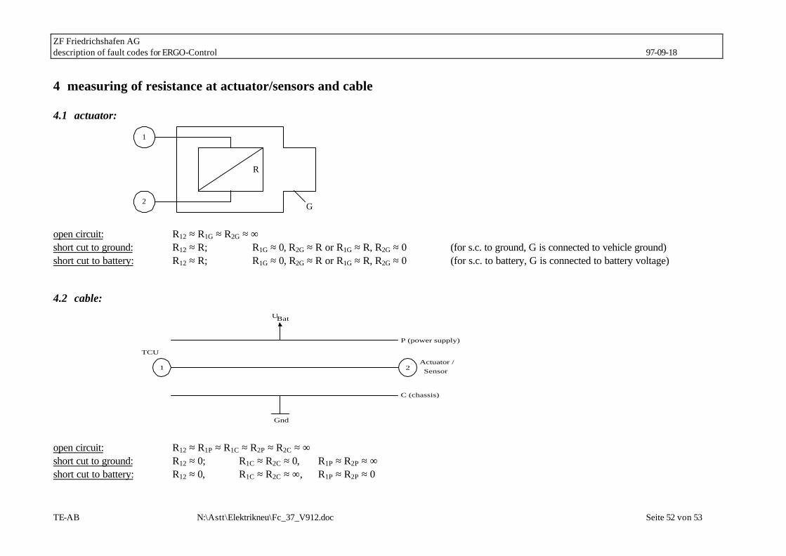
ZF Friedrichshafen AG description of fault codes for ERGO-Control 97-09-18
TE-AB N:\Astt\Elektrikneu\Fc_37_V912.doc Seite 52 von 53
4 measuring of resistance at actuator/sensors and cable
4.1 actuator:
R
2
1
G open circuit: R12 ≈ R1G ≈ R2G ≈ ∞ short cut to ground: R12 ≈ R; R1G ≈ 0, R2G ≈ R or R1G ≈ R, R2G ≈ 0 (for s.c. to ground, G is connected to vehicle ground) short cut to battery: R12 ≈ R; R1G ≈ 0, R2G ≈ R or R1G ≈ R, R2G ≈ 0 (for s.c. to battery, G is connected to battery voltage)
4.2 cable:
P (power supply)
1 2
TCU
Actuator /Sensor
UBat
Gnd
C (chassis)
open circuit: R12 ≈ R1P ≈ R1C ≈ R2P ≈ R2C ≈ ∞ short cut to ground: R12 ≈ 0; R1C ≈ R2C ≈ 0, R1P ≈ R2P ≈ ∞ short cut to battery: R12 ≈ 0, R1C ≈ R2C ≈ ∞, R1P ≈ R2P ≈ 0

ZF Friedrichshafen AG description of fault codes for ERGO-Control 97-09-18
TE-AB N:\Astt\Elektrikneu\Fc_37_V912.doc Seite 53 von 53
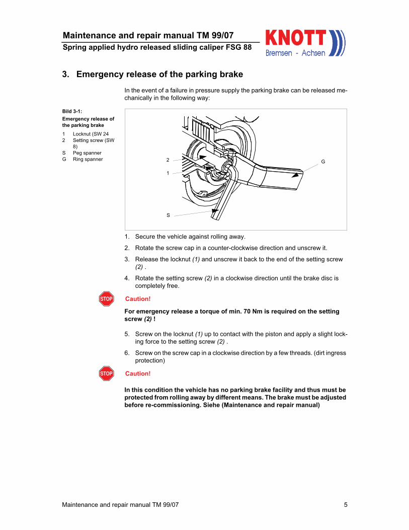
Maintenance and repair manual TM 99/07 5
Maintenance and repair manual TM 99/07
Spring applied hydro released sliding caliper FSG 88
3. Emergency release of the parking brake
In the event of a failure in pressure supply the parking brake can be released me-
chanically in the following way:
1. Secure the vehicle against rolling away.
2. Rotate the screw cap in a counter-clockwise direction and unscrew it.
3. Release the locknut (1) and unscrew it back to the end of the setting screw
(2) .
4. Rotate the setting screw (2) in a clockwise direction until the brake disc is
completely free.
Caution!
For emergency release a torque of min. 70 Nm is required on the setting
screw (2) !
5. Screw on the locknut (1) up to contact with the piston and apply a slight lock-
ing force to the setting screw (2) .
6. Screw on the screw cap in a clockwise direction by a few threads. (dirt ingress
protection)
Caution!
In this condition the vehicle has no parking brake facility and thus must be
protected from rolling away by different means. The brake must be adjusted
before re-commissioning. Siehe (Maintenance and repair manual)
Bild 3-1:
Emergency release of
the parking brake
1 Locknut (SW 24
2 Setting screw (SW
8)
S Peg spanner
G Ring spannerG2
1
S