cao module 1
TRANSCRIPT
8/7/2019 CAO Module 1
http://slidepdf.com/reader/full/cao-module-1 1/20
2011
Group1
S4 cs:
1/12/2011
Computer Architecture and
Organization

8/7/2019 CAO Module 1
http://slidepdf.com/reader/full/cao-module-1 2/20
BASIC STRUCTURES OF COMPUTERS-FUNCTIONAL UNITS-BASIC
OPERATIONAL CONCEPTS-BUS STRUCTURES-INSTRUCTION EQUENCING-
H/W AND S/W-ADDRESSING MODES-ASSEMPLY LANGUAGE-STACK ON
SUBROUTINES
Computer is a fast electronic calculating machine that accepts digitized input
information, processes it according to a list of internally stored instructions,and produces the
resulting output information. The list of instructions is called a computer program,and theinternal storage is called computer memory. Many types of computers exists that differ widely
in size, cost, computational power,and intended use. the most common computer is the
personal computer, which has found wide in homes, office, schools. It is the most common
form of desktop computers.Desktop computers have processing and storage units, visual
display and audio output units,and a keyboard that can all be located easily on a home or office
desks. the storage media includes hard disks, CD-ROMs and diskettes.
Super computer are the another type of computer, which is used for the large –scale
numerical calculations required in applications such as weather forecasting and aircraft design
and simulation.In enterprise sysytem, servers and supercomputers, the functional units,
including multiple processors, may consist of a number of separate and often large units.
FUNCTIONAL UNIT
A computer consist of five functionally independent main parts.They are input,
memory, arithmetic and logic, output and control unit.

8/7/2019 CAO Module 1
http://slidepdf.com/reader/full/cao-module-1 3/20
INPUT
I/O
OUTPUT
MEMORY
ARITHMETIC&
LOGIC UNIT
PROCESSOR
CONTROL
Instructions are explicit commamds that ,
I. govern the transfer of information within a computer as well as between the computer
and its I/O devices.
II. Specify the arithmetic and logic operations to be performed
III. A list of instructions that performs a task is called a program
INPUT UNIT
Computers accept coded information through input unit which read the data.The most
well known input device is the keyboard.Whenever a key is pressed the corresponding letter ordigit is automatically translated into its corresponding binary code and transmitted over a cable
to either the memory or the processor.
Eg: joystick, mouse
MEMORY UNIT
The function of the memory unit is to store programs and data.There are two classes of
storage called primary and secondary. Primary storage is a fast memory that operates atelectronic speed. The memory contains a large number of semiconductor storage cells each
capable of storing one bit of information.These cells are processed in groups or fixed size called
words. To provide easy access to any word in the memory,a distinct address is associated with
each word location.Adress are numbers that identify succesive location.
8/7/2019 CAO Module 1
http://slidepdf.com/reader/full/cao-module-1 4/20
The number of bits in each aord is reffered to as the word length of the
computer.Typical word length range from 16 to 64 bits.
Memory in which any location can be reached in a short and fixed amount of time after
specifying its address is called random access memory(RAM). The time required to access one
word is called memory access time. The small fast RAM units are called cashe. They are coupled
with the processor to achieve high performance. The largest and slowest unit is reffered to as
main memory.Primary storage is expensive. Thus additional cheaper secondary storage is used,
when large amount of data.
Eg:magnetic disk,tape, disk.
ARITHMETIC AND LOGIC UNIT
Any arithmetic or logic operation such as addition, subtraction, multiplication, division
or comparison of number is initiated by bringing the required operands into the processors,
where the operation is performed by ALU. When operands are brought into processor, they are
stored in high speed storage elements called registers.
OUTPUT UNIT
Output unit is the counter part of input unit.Its function is to send processed result to
the outside world.The most familiar output device is printer.
CONTROL UNIT
The memory arithmetic & logic and i/o units are co ordinated by the control unit.The
controlled unit is effectively the nerve centre that sends control signal to other units and
sennse their state. Timing signals are signals that determines when a given action is to teke
place. Data transfer between the processor and memory are also controlled by the control unit
by generating timing signals.
Summary:
I. Computer accepts information in the form of programs and data through on
input unit and stores it in the memory.
II. Information stored in the memory is fetched under the program control into an
arithmetic and logic unit where it is processed
III. Processed information leaves the computer through an output unit
IV. Whole activities inside the machine are directed by the control unit.

8/7/2019 CAO Module 1
http://slidepdf.com/reader/full/cao-module-1 5/20
BASIC OPERATIONAL UNIT
To performored a given task,an appropriate program consisting of a list of instructions is
stored in the memory. Individual instructions are brought from the memory in to the
processor,which executes the specified operations.Data to be used as operands are also stored
in the memory.
Eg:add LOCA,R0 adds the p[erands at memory locations LOCA to the operand in a
register in the processor, R0. The original concepts of locations LOCA are reversed whereas
those of R0 are overwritten.
The instruction requires several steps.
I. The instruction is fetched from the memory into the processor.
II. The operand at LOCA is fetched and added to contents of R0.
III. Finally, the resulting sum is stored in register, R0
Transfers between memory and processor are started by sending the address of the
memory location to be accessed to the memory unit and issuing the appropriate control signals.
The data are then transferd to or from the memory.
MEMORY
MAR MDR
PC
IR
CONTROL
R0
R1
…
Rn-1
ALU

8/7/2019 CAO Module 1
http://slidepdf.com/reader/full/cao-module-1 6/20
The above figure shows how the memory and the processor can be connected.In
addition to ALU and control circuitry, the processor contains a number of registers used for
several purposes. The instruction register IR holds the instructions that is currently being
executed.Its output is available to the control circuit which generate the timing signals that
controls the various processing elements involved in executing the instruction. The program
conter, PC is another specialized register. It keeps track of the execution of the program.It
contains the memory address of the next instruction to be fetdhed and executed. During
execution of an instruction, the contents of pc are updated to correspond to the address of the
next instruction to be executed.
The memory address register, MAR holds the address of the location to be accessed.
The memory data register, MDR contains the data to be written into or read out of the
addressed location.
Execution of the program starts PC is set to point to the first instruction of the program.
The contents of the pc are transferred to MAR and a read control signal is send to the memory.
After the required time to access the memory ellapses, the addressed word is read out of the
memory and located into MDR. Next the contents of MDR are transfered to IR. All this point the
instruction is ready to be decoded and executed.
If the instruction involves an operation to be performed by ALU, it is neccerrary to
obtain the required operand resides in the memory, it has to be fetched by sending its address
to the MAR and initiating a read cycle. When an operand has been read from memory to MDR,it is transferred from MDR to the ALU. After one or more operands are fetched in this way,
ALU can perform desired operation. If the result to this operation is to be stored in the
memory, then the result is send tp the MDR. The address of the location where the result is to
be stored is send to the MAR and a write cycle is initiated.At some point, during the execution
of the current instruction, the contents of pc are incremented such that pc points to the next
instruction to be executed.
Normal execution of programs may be preempted if some device requires urgent
servicing. To do this,the device raises an interept signal.An interrupt is a request from an i/o
device for service for service by the processor. The processor provides the requsted service by
executing an appropriate interrupt service routine. The contents of pc, general registers and
some controlled information are stored in the memory. When the interrupt service routine is
complete, the state of the processer is restored so that the interrupted program may continue.

8/7/2019 CAO Module 1
http://slidepdf.com/reader/full/cao-module-1 7/20
BUS STRUCTURES
To achieve a reasonable speed of operation a computer must be organized so that all its
units can handle one full word of data at a given time. When a word of data is transferred
between units, all its bits are transferd in parellel ie, the bits are transferd in parellel ie, all its
bits are transferd simutaneosly over many wires or lines, one bit per line. A group lines that
serves as a connecting path for several devices is called a bus.In addition to the lines that carry
the data, the bus must have lines foraddress and contol purposes. The simplest way to
interconnect functional unit is to use a single bus.
INPUT OUTPUT MEMORY PROCESSOR
The main advantage of single bus structure is its low cost and flexibility for attatching peripheral
devices.
The devices connected to the bus vary widely in their speed of operation. Keyboard and printers
are relatively slow, whereas memory and processor unit operate at electronic speed. All these devices
must communicate with each other over a bus. A common approach is to improve buffer registers with
the devices to hold the information during transfer.
E.g.: printer
Buffer registers smooth out timing differences among processor, memory and i/o devices. They
prevent high speed processor from being locked to a slow i/o device during a sequence of data transfer.

8/7/2019 CAO Module 1
http://slidepdf.com/reader/full/cao-module-1 8/20
INSTRUCTION AND INSTRUCTION SEQUENCING
A computer must have instruction capable of performing 4 types of operations
1. Data transfer b/w memory and processor register2. Arithmetic and logic operation on data
3. Program sequencing and control
4. Input output transfer
REGISTER TRANSFER NOTATION
The expression R1 to [loc] means that the contents of memory location LOC are
transferred into processor register R1. R3 [R1]+[R3] adds the contents of R1 and R2 and then
places their sum into register R3. This type of notation is called register transfer notation,RTN.
The right hand side of RTN expression always denotes a value and the left hand side is thename of a location where the value is to be placed, overwriting the old contents of that
location.
ASSEMBLY LANGUAGE NOTATION
An instruction that causes the transfer from memory location LOC to processor register
R1 is specified by the statement. MOVE LOC, R1.
The contents of LOC are unchanged by the execution of this instruction but the old
contents of register R1 are overwritten.
ADD R1, R2, R3 add two numbers contained in processor register R1 and R2 and placing
their sum in R3.
BASIC INSTRUCTION TYPES
The statement C=A+B in high level language program is a command to the computer to
add the contents of two variables A and B and to assign the sum to a third variable C. These
three variables are assigned to distinct locations A&B are fetched from the memory and
transferred into the processor, where the sum is computed . The result is then send back to the
memory and stored in location C.
Three address instruction can be represented as ADD A,B,C.
Operands A and B are called source operands is called destination operand and Add is
the operation to be performed on the operands. A general instruction of this type has the

8/7/2019 CAO Module 1
http://slidepdf.com/reader/full/cao-module-1 9/20
format, operation source 1, source 2, destination. A two address instruction is of the form,
operation source, and destination.
Eg: ADD A, B, which performs B = [A]+[B]. Operand B is both a source and a destination.
The operation C [A] + [B] can be performed by two instruction sequences,
MOVE B, C and ADD A, C.
The 1-address instruction ADD A adder the contents of memory location A to the
contents of accumulator register and place the sum back to the accumulator. C = [A]+[B] can
be performed as LOAD A, ADD B, STORE C where Load A copies contents of memory location A
into accumulation. ADD B adds the contents of memory location with the contents of and store
in it accumulator. STORE C copies and contents of accumulator into C.
The speed with which a given task is carried out depends on the time it takes to transfer
instruction from memory into the processor and to access the operands referenced by thisinstruction. Transfers that involve the memory are much slower than transfers within the
processor. A substantial increase in speed is achieved when several operations are performed
in succession on data in processor register without the need to copy data to or from the
memory.
INSTRUCTION EXECUTION AND STRAIGHT LINE SEQUENCING
PC contains address of next instruction. The information in the pc to fetch and execution
one at a time in the order of increasing address. This is called straight line sequencing.
Executing a given instruction is a two phase procedure. In the first phase, called
instruction fetch, the instruction is fetched from the memory location whose address is in the
PC. This instruction is placed in the IR in the processor.
BRANCHING
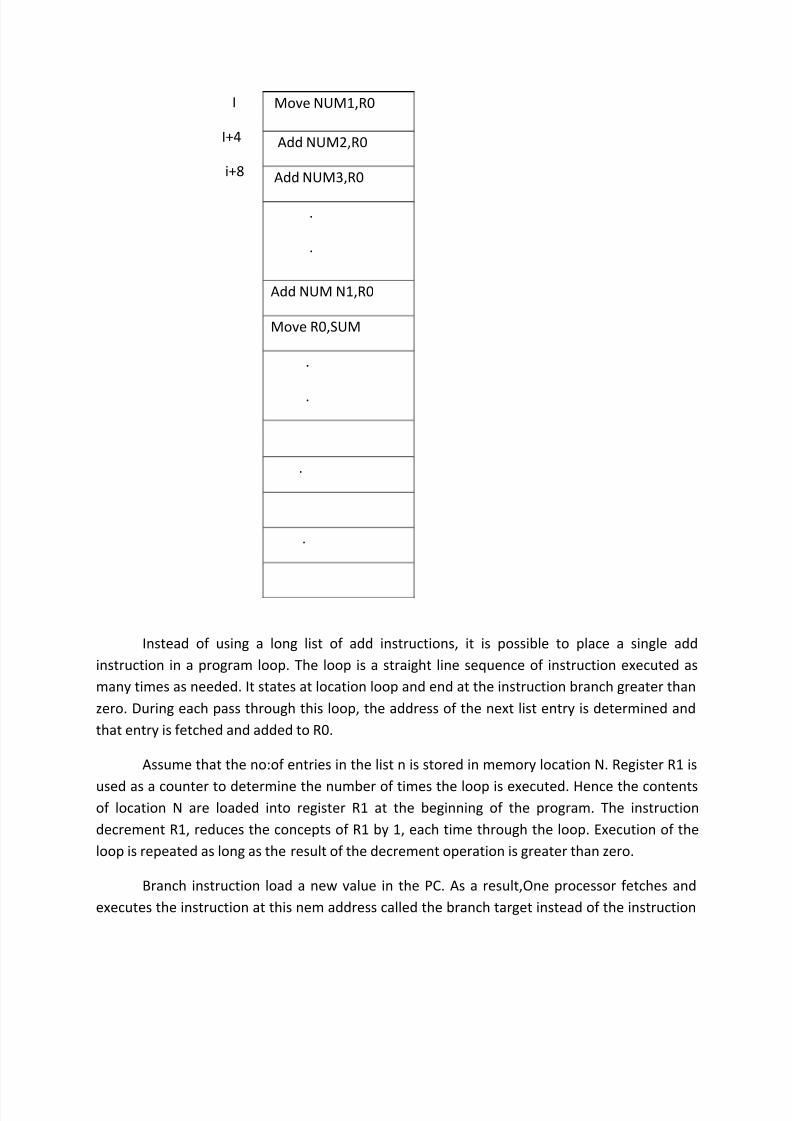
Consider the task of adding a list of n numbers. The addresses of the memory locations
containing the n numbers are symbolically given as num 1, num 2, ….num n and a separate add
instruction is used to add each number to the of register contents R0.After all the numbers has
been added, result is added in the memory location R0.
8/7/2019 CAO Module 1
http://slidepdf.com/reader/full/cao-module-1 10/20
I
I+4
i+8
Instead of using a long list of add instructions, it is possible to place a single add
instruction in a program loop. The loop is a straight line sequence of instruction executed as
many times as needed. It states at location loop and end at the instruction branch greater than
zero. During each pass through this loop, the address of the next list entry is determined and
that entry is fetched and added to R0.
Assume that the no:of entries in the list n is stored in memory location N. Register R1 is
used as a counter to determine the number of times the loop is executed. Hence the contentsof location N are loaded into register R1 at the beginning of the program. The instruction
decrement R1, reduces the concepts of R1 by 1, each time through the loop. Execution of the
loop is repeated as long as the result of the decrement operation is greater than zero.
Branch instruction load a new value in the PC. As a result,One processor fetches and
executes the instruction at this nem address called the branch target instead of the instruction
Move NUM1,R0
Add NUM2,R0
Add NUM3,R0
.
.
Add NUM N1,R0
Move R0,SUM
.
.
.
.

8/7/2019 CAO Module 1
http://slidepdf.com/reader/full/cao-module-1 11/20
at the location. A conditional branch instruction causes a branch only if a specified condition is
satisfied. If the condition is not satisfied, PC is implemented in the normal way and the next
instruction in sequential address order is fetched.
CONDITION CODES
The processor keeps track of information about the results of various operations for use
by subsequent conditional branch instructions. This is accomplished by recording the required
information in individual bits often called condition code flags. These flags are usually grouped
together in a special processor register called the condition code register or status register.
Individual condition code flags are set to 1 or cleared to zero, depending on the outcome of theoperation performed.
Commonly used flags are
(i) NEGATIVE FLAG (N):
This flag is set to 1 if the result is negative otherwise cleared to zero.
Move N1,R1
Clear R0
Determine add of’Next’
Number and add next
number to R0
Decrement R0
Branch>0 LOAD
Move R0,SUM
.
.

8/7/2019 CAO Module 1
http://slidepdf.com/reader/full/cao-module-1 12/20
(ii) ZERO FLAG (Z):
This flag is set to 1 if the result is zero otherwise cleared to zero
(iii) OVERFLOW FLAG(V):
This flag is set to 1 if arithmetic overflow occurs, otherwise cleared to zero
(iv) CARRY FLAG(C):
This flag is set to 1 if a carry out results from the operation, otherwise cleared to zero
The N and Z flags are affected by instructions that transfer data such as move, load and
store flag indicates whether overflow has taken place. Overflow occurs when the result of an
arithmetic operation is outside the range of values that can be represented by the number of
bits available for the operands.
The carry flag is set to 1 if a carry occurs from the most significant bit position during an
arithmetic operation. This flag make it possible to perform arithmetic operation on operands
that are larger than the word length of the processor
The instruction branch>0 is an E.g. of a branch instruction that tests one or more of the
condition flags . It causes a branch, if the value tested is neither negative nor equal to zero
8/7/2019 CAO Module 1
http://slidepdf.com/reader/full/cao-module-1 13/20
ADDRESSING MODES
The different ways in which the location of an operand is specified in an instruction are
referred to as addressing modes.
IMPLEMENTATION OF VARIABLES AND CONSTANT
Variables and constants are the simplest data types and are found in almost every
computer program. In assembly language, a variable is represented by allocating a register or
a memory location to hold its value. Thus the value can be changed as needed using
appropriate instructions. There are several addressing modes:
1. REGISTER MODE
The operand is the contents of a processor register, the name(address) of the register
is given in the instruction
2. ABSOLUTE MODE(Direct)
The operand is in a memory location, the address of this location is given explicitly in the
instruction. This mode is also known as direct mode
The instruction Move LOC, R2 uses these 2 modes .Processor registers are used as
temporary storage locations,Where the data in a aregister are accessed using the register
mode.The absolute mode can represent global variables in a program.
3. IMMEDIATE MODE
The operand is given explicitly in the instruction.for eg the instruction Move 200
immidiate, R0 places the value 200 in register R0. Immediate mode is only used to specify the
value of a source operand. A common convention is to use the sharp sign infront of the value to
indicate that this value is to be used as as immediate operand. Hence we write the above
instruction in the form MOVE # 200, R0
A=B+6
MOVE B, R1
ADD # 6, R1
MOVE R1, A
4. INDIRECTION AND POINTERS
It provides information from which the memory address of the operand can be
determined. We refer to this address as effective address (EA) of the operand
5. INDIRECT MODE
8/7/2019 CAO Module 1
http://slidepdf.com/reader/full/cao-module-1 14/20
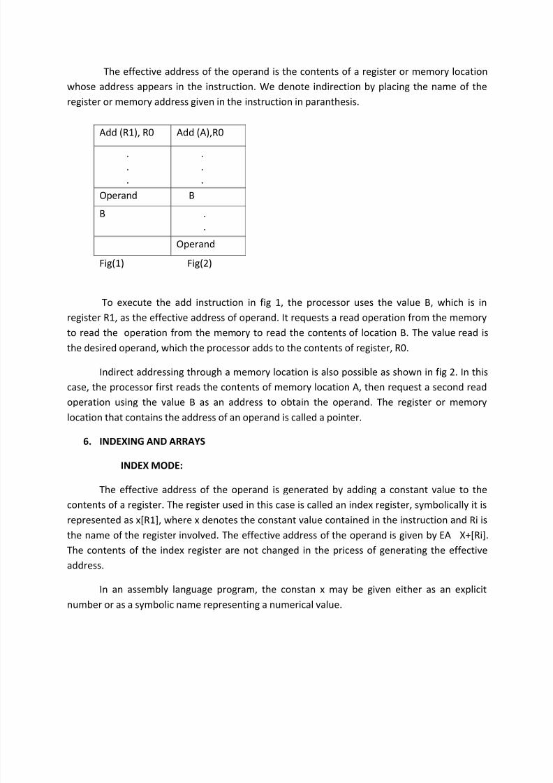
The effective address of the operand is the contents of a register or memory location
whose address appears in the instruction. We denote indirection by placing the name of the
register or memory address given in the instruction in paranthesis.
Add (R1), R0 Add (A),R0
.
.
.
.
.
.
Operand B
B .
.
Operand
Fig(1) Fig(2)
To execute the add instruction in fig 1, the processor uses the value B, which is in
register R1, as the effective address of operand. It requests a read operation from the memory
to read the operation from the memory to read the contents of location B. The value read is
the desired operand, which the processor adds to the contents of register, R0.
Indirect addressing through a memory location is also possible as shown in fig 2. In this
case, the processor first reads the contents of memory location A, then request a second read
operation using the value B as an address to obtain the operand. The register or memory
location that contains the address of an operand is called a pointer.
6. INDEXING AND ARRAYS
INDEX MODE:
The effective address of the operand is generated by adding a constant value to the
contents of a register. The register used in this case is called an index register, symbolically it is
represented as x[R1], where x denotes the constant value contained in the instruction and Ri is
the name of the register involved. The effective address of the operand is given by EA X+[Ri].
The contents of the index register are not changed in the pricess of generating the effectiveaddress.
In an assembly language program, the constan x may be given either as an explicit
number or as a symbolic name representing a numerical value.

8/7/2019 CAO Module 1
http://slidepdf.com/reader/full/cao-module-1 15/20
7. RELATIVE ADDRESSING
The effective address is determined by the index mode using the program counter in
place of the general purpose register Ri.
The X[PC] can be used to address a memory location that is x bytes away from thelocation presently pointed to by the program counter. Since the addressed location is identified
relative to the pc, the name relative mode is associated with the type of addressing.
This mode can be used to access data operands but its most common use is to specify
the target address in branch instruction such as, branch>0 loop causes program execution to go
to the branch target location identified by the name loop if the branch condition is satisfied.
This location can be computed by specifying it as an offset from the current value of the PC.
ADDITIONAL MODES:
1) Auto increment mode
The effective address of the operand is the contents of a register specified in the
instruction. After accessing the operand,the contents of this register are automatically
incremented to point to next item in a list. We denote the auto increment made by putting the
specified register is parenthesis to show that contents of register are ujsed as effective address,
followed by a ‘+’ sign to indicate that these contents are to be incremented after the operand is
accessed.Auto increment mode written as (Ri)+.
2) Auto decrement mode
The contents of a register specified in the instruction are first automatically
decremented and are then used as effective address of the operand.We denote the auto
decrement mode by putting the specified register in parenthesis preceded by a ‘–‘ sign to be
indicate that the contents of register are to be decremented before being used as effective
address.
ASSEMBLY LANGUAGEMachine instruction are represented by patterns of zeros and ones.We use symbolic
names to represent the patterns. Such words are normally replaced by achronyms called
mnemonics. Such as MOV, ADD, INC ,BR.

8/7/2019 CAO Module 1
http://slidepdf.com/reader/full/cao-module-1 16/20
A complete set of such sybolic names and rules for their use constitute a programming
language called assembly language. The set of rules for using the mnemonics in the
specification of complete instruction and programs is called the syntax of the language.
Program written in an assembly language can be automatically translated into a
sequence of machine instruction by a program called an assembler. The assembler is stored as a
sequence of machine instructions in the memory of the computer. The user program in its
original alpha-numeric text format is called source program and the assembled machine
language program is called object program.
In the MOV instruction, MOVE R0, SUM the mnemonic MOVE represents the binary
pattern or opcode, for the operation perform by the instruction. The assembler translates this
mnemonic into the binary opcode that the computer understand.
The opcode mnemonic is followed by atleast ane blankspace character. Then the
information that specifies the operands is given in this e.g, the source operand is in register
R0.This information is followed by specification of the destination operand, seperated from the
source operand by a comma. The destination operand is in memory location that has its binary
address represented by the name SUM.
ASSEMBLER DIRECTIVES
In addition to providing a mechanism instructions in a program, the assembly language
allows allows the programmer to specify other information needed to translate the source
program into object program. Suppose that the name sum is used to represent the value 200.
This can be represented as SUM EQU 200. This statement does not denote an instruction that
will be executed when the object program is run;it will not appear in the object program.It
simply informs the assembler that the name sum should be replaced by the value 200 wherever
it appears in the program.Such statementa are called assembler directives. They are used by
the assembler directives. They are used by the assembler while it translates a source program
into an object program.
MEMORY ADDRESS LABEL OPERATION ADDRESS OR DATA
INFORMATION
SUM EQE
ORIGIN
200
204
N DATAWORD 100

8/7/2019 CAO Module 1
http://slidepdf.com/reader/full/cao-module-1 17/20
NUM1 RESERVE
ORIGIN
400
100
START MOVE
MOVE
N,R1
# NUM1,R2
LOOP CLR
ADDDEC
BGTZ
MOVE
RETURN
END
R0
(R2),R0#4,R2
R1
LOOP
R0,SUM
START
The program begins with assembler directives.The equate directive EQU informs the
assenbler about the value of SUM.The second assembler directive ORIGIN then the assembler
program where in the memory to place the datablocks.In this case, one location specified hasthe address 204.Since this location is to be loaded with the value 100 a data word directive is
used to inform the asssembler of this required.
Any statement that results in instructions or data being placed in a memory location
may be given memory address label.The label is assighned a value equal to the address of that
location.
The RESERVE directive declares that a memory block of 400 bytes is to be reserved for
data and that the name NUM1 is to be associated with address 208.
The second ORIGIN directive specifies that the instructions of the object program are to
be loaded in the memory starting at address 100. The last statement in the source program is
the assembler directive END which tells the assembler that this is the end of the source
program text. The END directive includes the label START which is the address of the location at
which execution of the program is to begin.
ASSEMBLY AND EXECUTION OF PROGRAM
As the assembler scans through a source program, it keeps track of all names and
numerical values that correspond to them in a symbol table. Thus when a name appears a
second time, it is replaced with its value from the table.A problem arises when this happens if a
forward branch is required. The assembler will not be able to determine the branch target
because the name referred to has not yet being recorded in the symbol table. A simple solution
to this problem is to have the assembler scan through the source program twice. During the
8/7/2019 CAO Module 1
http://slidepdf.com/reader/full/cao-module-1 18/20
first pass, it creates a complete symbol table.At the end of this pass, all names will have been
assigned numerical values. The assembler then goes through the source program a second time
and substitute values for all names from the symbol table.Such an assembler is called two pass
assembler.
STACK
A stack is a list of data elements, with the accessing restriction that elements can be
added or removed at one end of the list only. This end is called top of the stack and the other
end is called bottom. This structure is reffered to as push down stack.Here the elements last
inserted is removed first. Hence it is also called last in first out(LIFO) data structure. The terms
push and pop are used to describe placing a new item on the stack respectively.
A processor register is used to keep track of the address of the element of the stack that
is at the top, at any given time this register is called the stack pointer(SP).
SUBROUTINES
In a given program it is often necessary to perform a particular subtask many times on
different data values.Such a subtask is usually called a subroutine. When a program branches to
a subroutine, we say that it is calling the subroutine. The instruction that performs this branch
operation is named as call instructions.
After a subroutine has been executed, the calling program must resume execution,
continuing immediately after the instruction that called the subroutine. The subroutine is said
to return to the program that called it by executing a return instruction. Hence the contents of
the PC must be saved by the call instruction to enable correct return to the calling program
The way in which a computer makes it possible to call and return from subroutines is
reffered to as subroutine linkage method. The simplest subroutine linkage method is to save
the return address in a specific location which may be a register dedicated to the function.Such
a register is called link register.
The call instruction is a special branch instruction that performs the following
i. Store the contents of PC in the link register
ii. Branch of the target address specified by the instruction.The return instruction is a
special branch instruction that performs the operation, branch, to the address
contained

8/7/2019 CAO Module 1
http://slidepdf.com/reader/full/cao-module-1 19/20
SUBROUTINE NESTING AND THE PROCESSOR STACK
Subroutine nesting can be carried out to any depth. The last subroutine called
completes its computation and returns to the subroutine that called it. The return address
needed for this first return is the last one generated in the nested call sequence.ie, return
addresses are generated and used in a last in first out order. This suggests that return addresses
associated with subroutine calls should be pushed into a stack. A particular register is designed
as the stack pointer, SP to be used in this operation.The stack pointer points to a stack called
the processor stack
SOFTWAR
System software is a collection of program that are executed as needed to perform
function such as:
Receiving and interpreting user commands
Entering and editing application program and storing them as files in sorage
devices
Managing the storage and retrival of files in storage devices
Running standard application programs such as word processor
Controlling i/o unots to receive i/p information and produce o/p device
Translating program from source from prepared by the user in to object
Linking and runnung are written application programs with existing standard
library routines such as numerical computation packages

8/7/2019 CAO Module 1
http://slidepdf.com/reader/full/cao-module-1 20/20