ems btdin - universal control module f80bc - bticinoems btdin - universal control module f80bc cat....
TRANSCRIPT
1 / 16
Viale Borri 231,
21100 Varese - Italy
EMS BTDIN - Universal control
module
Cat. N°:
F80BC
Contents Pages
1. Description - Use ........................................................ 2
2. Range ......................................................................... 2
3. Overall dimensions ..................................................... 2
4. Preparation - Connection ............................................ 2
5. General characteristics ............................................... 7
6. System architectures ................................................. 10
6.1 Stand alone ........................................................... 10
6.1.1 with local addressing........................................ 10
6.1.2 with remote addressing .................................... 11
6.2 Supervised ............................................................ 12
6.2.1 with local addressing........................................ 12
6.2.2 with remote addressing .................................... 14
7. Compliance and approvals ........................................ 16
Product information: IDP000155EN_01 Updated: - Created: 09/03/2017
2 / 16
EMS BTDIN - Universal control
module
Cat. N°:
F80BC
1. DESCRIPTION - USE
. Module dedicated to Energy Management System (EMS BTDIN)
use.
. Enables to remotely command different electrical loads and motor
driven control modules of modular devices (MCBs, RCCBs,
RCBOs...) or power devices (e.g. MCCBs...).
. Equipped with DIP switches (on the side) allowing product
configuration of:
- contacts type (NO or NC contacts)
- working method (maintained or momentary contact)
Symbol:
2. RANGE
. Cat. n° F80BC: Universal Control Module, with 2 configurable
relays 250 V~ -6 A contacts
Width:
. 1 module. 17,8 mm width.
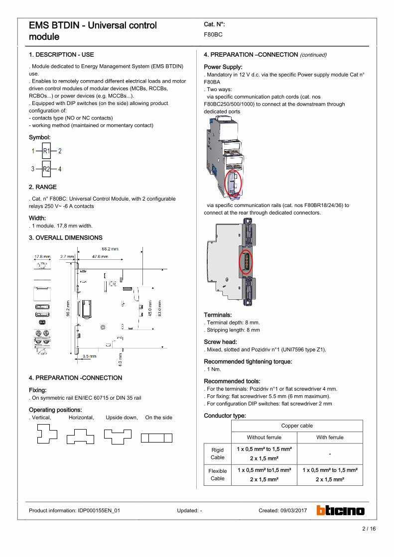
3. OVERALL DIMENSIONS
4. PREPARATION -CONNECTION
Fixing:
. On symmetric rail EN/IEC 60715 or DIN 35 rail
Operating positions:
. Vertical, Horizontal, Upside down, On the side
4. PREPARATION –CONNECTION (continued)
Power Supply:
. Mandatory in 12 V d.c. via the specific Power supply module Cat n°
F80BA
. Two ways:
via specific communication patch cords (cat. nos
F80BC250/500/1000) to connect at the downstream through
dedicated ports
via specific communication rails (cat. nos F80BR18/24/36) to
connect at the rear through dedicated connectors.
Terminals:
. Terminal depth: 8 mm.
. Stripping length: 8 mm
Screw head:
. Mixed, slotted and Pozidriv n°1 (UNI7596 type Z1).
Recommended tightening torque:
. 1 Nm.
Recommended tools:
. For the terminals: Pozidriv n°1 or flat screwdriver 4 mm.
. For fixing: flat screwdriver 5.5 mm (6 mm maximum).
. For configuration DIP switches: flat screwdriver 2 mm
Conductor type:
Copper cable
Without ferrule With ferrule
Rigid
Cable
1 x 0,5 mm² to 1,5 mm²
2 x 1,5 mm² -
Flexible
Cable
1 x 0,5 mm² to1,5 mm²
2 x 1,5 mm²
1 x 0,5 mm² to 1,5 mm²
2 x 1,5 mm²
Product information: IDP000155EN_01 Updated: - Created: 09/03/2017
3 / 16
EMS BTDIN - Universal control
module
Cat. N°:
F80BC
4. PREPARATION –CONNECTION (continued)
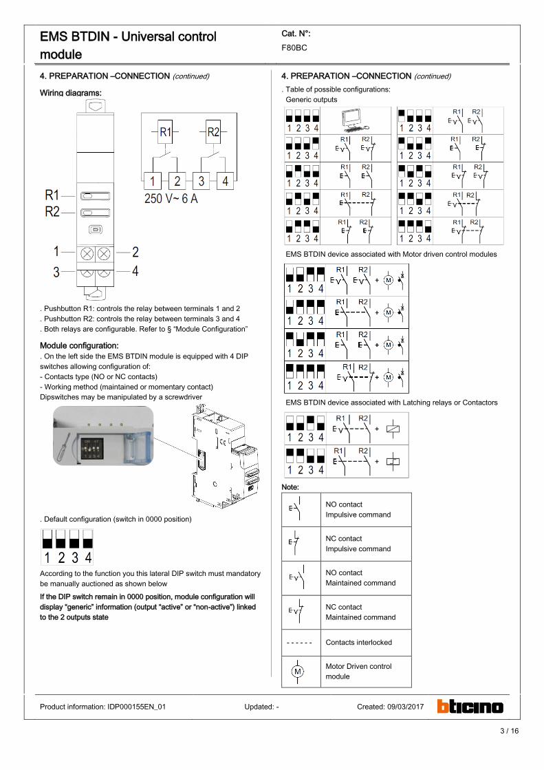
Wiring diagrams:
. Pushbutton R1: controls the relay between terminals 1 and 2
. Pushbutton R2: controls the relay between terminals 3 and 4
. Both relays are configurable. Refer to § “Module Configuration”
Module configuration:
. On the left side the EMS BTDIN module is equipped with 4 DIP
switches allowing configuration of:
- Contacts type (NO or NC contacts)
- Working method (maintained or momentary contact)
Dipswitches may be manipulated by a screwdriver
. Default configuration (switch in 0000 position)
According to the function you this lateral DIP switch must mandatory
be manually auctioned as shown below
If the DIP switch remain in 0000 position, module configuration will
display “generic” information (output “active” or “non-active”) linked
to the 2 outputs state
4. PREPARATION –CONNECTION (continued)
. Table of possible configurations:
Generic outputs
EMS BTDIN device associated with Motor driven control modules
EMS BTDIN device associated with Latching relays or Contactors
Note:
NO contact
Impulsive command
NC contact
Impulsive command
NO contact
Maintained command
NC contact
Maintained command
- - - - - - Contacts interlocked
Motor Driven control
module
Product information: IDP000155EN_01 Updated: - Created: 09/03/2017
4 / 16
EMS BTDIN - Universal control
module
Cat. N°:
F80BC
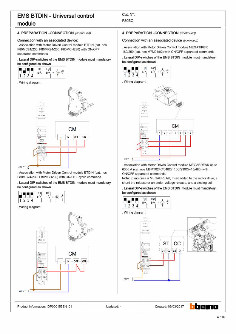
4. PREPARATION –CONNECTION (continued)
Connection with an associated device:
. Association with Motor Driven Control module BTDIN (cat. nos
F80MC24/230, F80MR24/230, F80MCH230) with ON/OFF
separated commands
. Lateral DIP-switches of the EMS BTDIN module must mandatory
be configured as shown
. Wiring diagram:
. Association with Motor Driven Control module BTDIN (cat. nos
F80MC24/230, F80MCH230) with ON/OFF cyclic command
. Lateral DIP-switches of the EMS BTDIN module must mandatory
be configured as shown
. Wiring diagram:
4. PREPARATION –CONNECTION (continued)
Connection with an associated device (continued):
. Association with Motor Driven Control module MEGATIKER
160/250 (cat. nos M7M01/02) with ON/OFF separated commands
. Lateral DIP-switches of the EMS BTDIN module must mandatory
be configured as shown
. Wiring diagram:
. Association with Motor Driven Control module MEGABREAK up to
6300 A (cat. nos M8MT024C/048C/110C/230C/415/480) with
ON/OFF separated commands.
Note: to motorise a MEGABREAK, must added to the motor drive, a
shunt trip release or an under-voltage release, and a closing coil
. Lateral DIP-switches of the EMS BTDIN module must mandatory
be configured as shown
. Wiring diagram:
Product information: IDP000155EN_01 Updated: - Created: 09/03/2017
5 / 16
EMS BTDIN - Universal control
module
Cat. N°:
F80BC
4. PREPARATION –CONNECTION (continued)
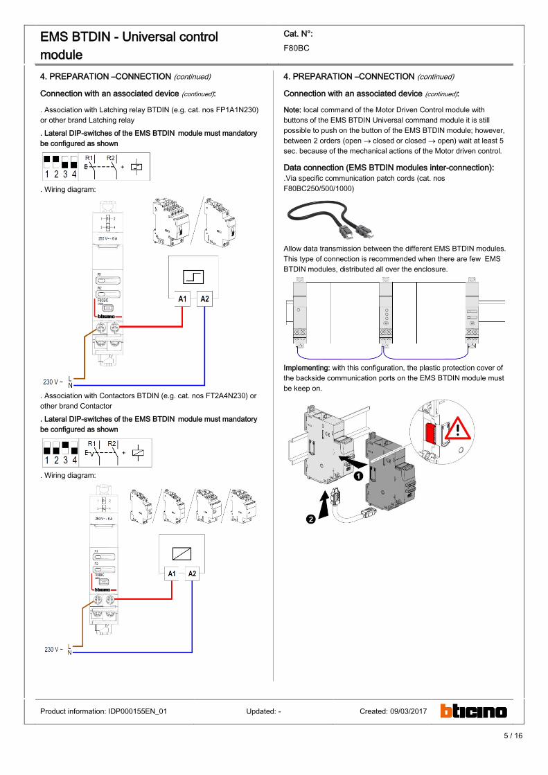
Connection with an associated device (continued):
. Association with Latching relay BTDIN (e.g. cat. nos FP1A1N230)
or other brand Latching relay
. Lateral DIP-switches of the EMS BTDIN module must mandatory
be configured as shown
. Wiring diagram:
. Association with Contactors BTDIN (e.g. cat. nos FT2A4N230) or
other brand Contactor
. Lateral DIP-switches of the EMS BTDIN module must mandatory
be configured as shown
. Wiring diagram:
4. PREPARATION –CONNECTION (continued)
Connection with an associated device (continued):
Note: local command of the Motor Driven Control module with
buttons of the EMS BTDIN Universal command module it is still
possible to push on the button of the EMS BTDIN module; however,
between 2 orders (open closed or closed open) wait at least 5
sec. because of the mechanical actions of the Motor driven control.
Data connection (EMS BTDIN modules inter-connection):
.Via specific communication patch cords (cat. nos
F80BC250/500/1000)
Allow data transmission between the different EMS BTDIN modules.
This type of connection is recommended when there are few EMS
BTDIN modules, distributed all over the enclosure.
Implementing: with this configuration, the plastic protection cover of
the backside communication ports on the EMS BTDIN module must
be keep on.
Product information: IDP000155EN_01 Updated: - Created: 09/03/2017
6 / 16
EMS BTDIN - Universal control
module
Cat. N°:
F80BC
4. PREPARATION –CONNECTION (continued)
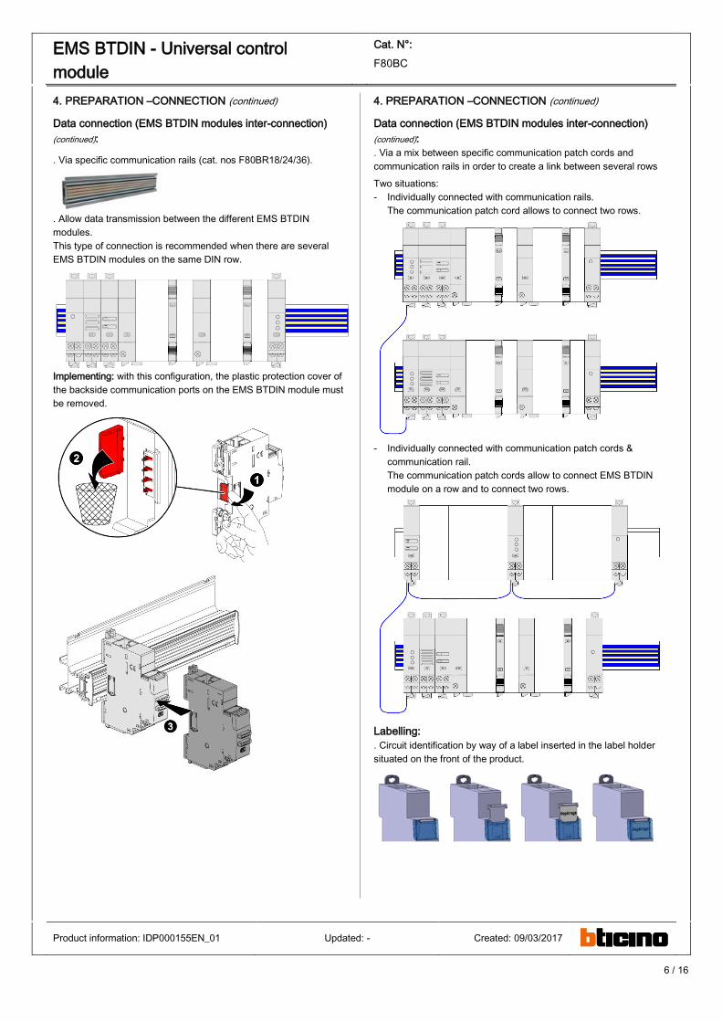
Data connection (EMS BTDIN modules inter-connection)
(continued):
. Via specific communication rails (cat. nos F80BR18/24/36).
. Allow data transmission between the different EMS BTDIN
modules.
This type of connection is recommended when there are several
EMS BTDIN modules on the same DIN row.
Implementing: with this configuration, the plastic protection cover of
the backside communication ports on the EMS BTDIN module must
be removed.
4. PREPARATION –CONNECTION (continued)
Data connection (EMS BTDIN modules inter-connection)
(continued):
. Via a mix between specific communication patch cords and
communication rails in order to create a link between several rows
Two situations:
- Individually connected with communication rails.
The communication patch cord allows to connect two rows.
- Individually connected with communication patch cords &
communication rail.
The communication patch cords allow to connect EMS BTDIN
module on a row and to connect two rows.
Labelling:
. Circuit identification by way of a label inserted in the label holder
situated on the front of the product.
Product information: IDP000155EN_01 Updated: - Created: 09/03/2017
7 / 16
EMS BTDIN - Universal control
module
Cat. N°:
F80BC
4. PREPARATION –CONNECTION (continued)
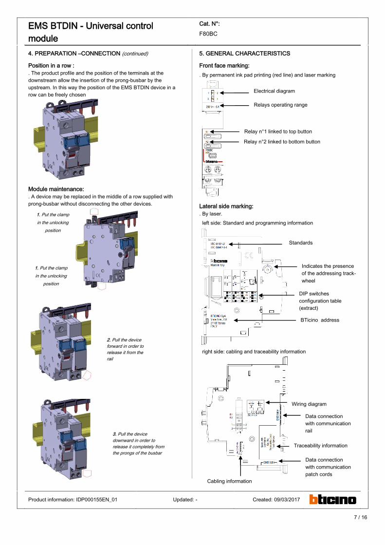
Position in a row :
. The product profile and the position of the terminals at the
downstream allow the insertion of the prong-busbar by the
upstream. In this way the position of the EMS BTDIN device in a
row can be freely chosen
Module maintenance:
. A device may be replaced in the middle of a row supplied with
prong-busbar without disconnecting the other devices.
5. GENERAL CHARACTERISTICS
Front face marking:
. By permanent ink pad printing (red line) and laser marking
Lateral side marking:
. By laser.
left side: Standard and programming information
right side: cabling and traceability information
Product information: IDP000155EN_01 Updated: - Created: 09/03/2017
1. Put the clamp
in the unlocking
position
1. Put the clamp
in the unlocking
position
2. Pull the device
forward in order to
release it from the
rail
3. Pull the device
downward in order to
release it completely from
the prongs of the busbar
Electrical diagram
Relays operating range
Relay n°1 linked to top button
Relay n°2 linked to bottom button
Standards
Indicates the presence
of the addressing track-
wheel
DIP switches
configuration table
(extract)
BTicino address
Wiring diagram
Traceability information
Data connection
with communication
rail
Data connection
with communication
patch cords
Cabling information
8 / 16
EMS BTDIN - Universal control
module
Cat. N°:
F80BC
5. GENERAL CHARACTERISTICS (continued)
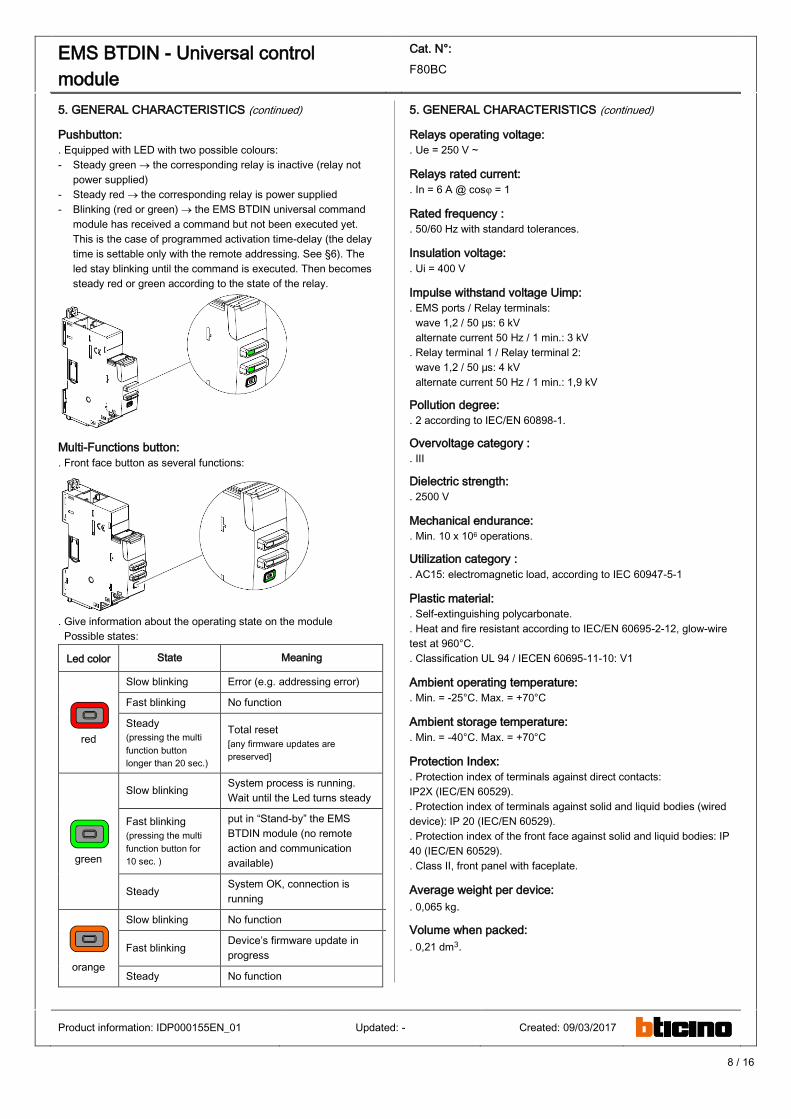
Pushbutton:
. Equipped with LED with two possible colours:
- Steady green the corresponding relay is inactive (relay not
power supplied)
- Steady red the corresponding relay is power supplied
- Blinking (red or green) the EMS BTDIN universal command
module has received a command but not been executed yet.
This is the case of programmed activation time-delay (the delay
time is settable only with the remote addressing. See §6). The
led stay blinking until the command is executed. Then becomes
steady red or green according to the state of the relay.
Multi-Functions button:
. Front face button as several functions:
. Give information about the operating state on the module
Possible states:
Led color State Meaning
red
Slow blinking Error (e.g. addressing error)
Fast blinking No function
Steady
(pressing the multi
function button
longer than 20 sec.)
Total reset
[any firmware updates are
preserved]
green
Slow blinking System process is running.
Wait until the Led turns steady
Fast blinking
(pressing the multi
function button for
10 sec. )
put in “Stand-by” the EMS
BTDIN module (no remote
action and communication
available)
Steady System OK, connection is
running
orange
Slow blinking No function P&L info (refer to next paragraph)
Fast blinking Device’s firmware update in
progress
Steady No function
5. GENERAL CHARACTERISTICS (continued)
Relays operating voltage:
. Ue = 250 V ~
Relays rated current:
. In = 6 A @ cosφ = 1
Rated frequency :
. 50/60 Hz with standard tolerances.
Insulation voltage:
. Ui = 400 V
Impulse withstand voltage Uimp:
. EMS ports / Relay terminals:
wave 1,2 / 50 μs: 6 kV
alternate current 50 Hz / 1 min.: 3 kV
. Relay terminal 1 / Relay terminal 2:
wave 1,2 / 50 μs: 4 kV
alternate current 50 Hz / 1 min.: 1,9 kV
Pollution degree:
. 2 according to IEC/EN 60898-1.
Overvoltage category :
. III
Dielectric strength:
. 2500 V
Mechanical endurance:
. Min. 10 x 106 operations.
Utilization category :
. AC15: electromagnetic load, according to IEC 60947-5-1
Plastic material:
. Self-extinguishing polycarbonate.
. Heat and fire resistant according to IEC/EN 60695-2-12, glow-wire
test at 960°C.
. Classification UL 94 / IECEN 60695-11-10: V1
Ambient operating temperature:
. Min. = -25°C. Max. = +70°C
Ambient storage temperature:
. Min. = -40°C. Max. = +70°C
Protection Index:
. Protection index of terminals against direct contacts:
IP2X (IEC/EN 60529).
. Protection index of terminals against solid and liquid bodies (wired
device): IP 20 (IEC/EN 60529).
. Protection index of the front face against solid and liquid bodies: IP
40 (IEC/EN 60529).
. Class II, front panel with faceplate.
Average weight per device:
. 0,065 kg.
Volume when packed:
. 0,21 dm3.
Product information: IDP000155EN_01 Updated: - Created: 09/03/2017
9 / 16
EMS BTDIN - Universal control
module
Cat. N°:
F80BC
5. GENERAL CHARACTERISTICS (continued)
Consumption:
. Values at 12 Vd.c.
Configuration W mA
Stand-by 0,265 22
2 Open contacts 0,265 22
1 Open contact &
1 Closed contact 0,375 31
2 Closed contacts 0,458 38
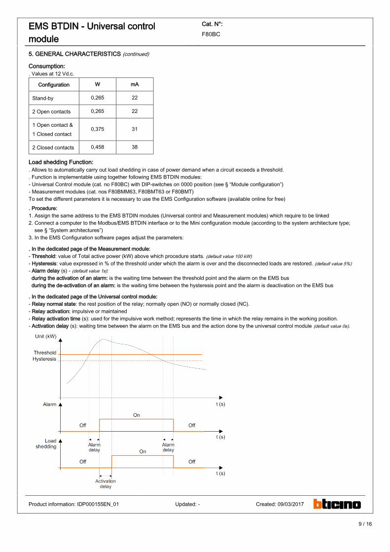
Load shedding Function:
. Allows to automatically carry out load shedding in case of power demand when a circuit exceeds a threshold.
. Function is implementable using together following EMS BTDIN modules:
- Universal Control module (cat. no F80BC) with DIP-switches on 0000 position (see § “Module configuration”)
- Measurement modules (cat. nos F80BMM63, F80BMT63 or F80BMT)
To set the different parameters it is necessary to use the EMS Configuration software (available online for free)
. Procedure:
1. Assign the same address to the EMS BTDIN modules (Universal control and Measurement modules) which require to be linked
2. Connect a computer to the Modbus/EMS BTDIN interface or to the Mini configuration module (according to the system architecture type;
see § “System architectures”)
3. In the EMS Configuration software pages adjust the parameters:
. In the dedicated page of the Measurement module:
- Threshold: value of Total active power (kW) above which procedure starts. (default value 100 kW)
- Hysteresis: value expressed in % of the threshold under which the alarm is over and the disconnected loads are restored. (default value 5%)
- Alarm delay (s) - (default value 1s):
during the activation of an alarm: is the waiting time between the threshold point and the alarm on the EMS bus
during the de-activation of an alarm: is the waiting time between the hysteresis point and the alarm is deactivation on the EMS bus
. In the dedicated page of the Universal control module:
- Relay normal state: the rest position of the relay; normally open (NO) or normally closed (NC).
- Relay activation: impulsive or maintained
- Relay activation time (s): used for the impulsive work method; represents the time in which the relay remains in the working position.
- Activation delay (s): waiting time between the alarm on the EMS bus and the action done by the universal control module (default value 0s).
Product information: IDP000155EN_01 Updated: - Created: 09/03/2017
10 / 16
EMS BTDIN - Universal control
module
Cat. N°:
F80BC
6. SYSTEM ARCHITECTURES
The EMS BTDIN is a polyvalent system and, according to the needs of the customer, can be set up and/or used as “Stand-alone” or
“Supervised” system. Based on this choice the configuration and addressing methods are different.
Four possible architectures are provided:
6.1 Stand alone system
6.1.1 with local addressing (through the track wheel)
6.1.2 with remote addressing (through a computer)
6.2 Supervised (Computer Supervisory System)
6.2.1 with local addressing
6.2.2 with remote addressing
6.1 Stand-alone system
. Stand alone = autonomous system. To be used by the end-user if it is not necessary to have a computer for the supervision outside the
envelope. Everything can be manage on site.
6.1.1 Stand-alone system with local addressing (through the track wheel)
Local addressing advantages:
- No configuration software needed to set-up the installation
- It is not necessary to use a computer to manage settings (configurations, test, ...) and to use the system (visualize and be alerted,
...). Everything can be done through the Mini configuration module (local display, cat. no F80BV). [Refer to the technical sheet dedicated to
this module for details].
- No communication Interfaces or gateways are required.
- Installation can be done without the intervention of a System Integrator
Programming procedure:
. For EMS BTDIN modules which need some: mandatory through to lateral DIP-switch of each EMS BTDIN modules (see § ”Module
configuration”)
Addressing procedure:
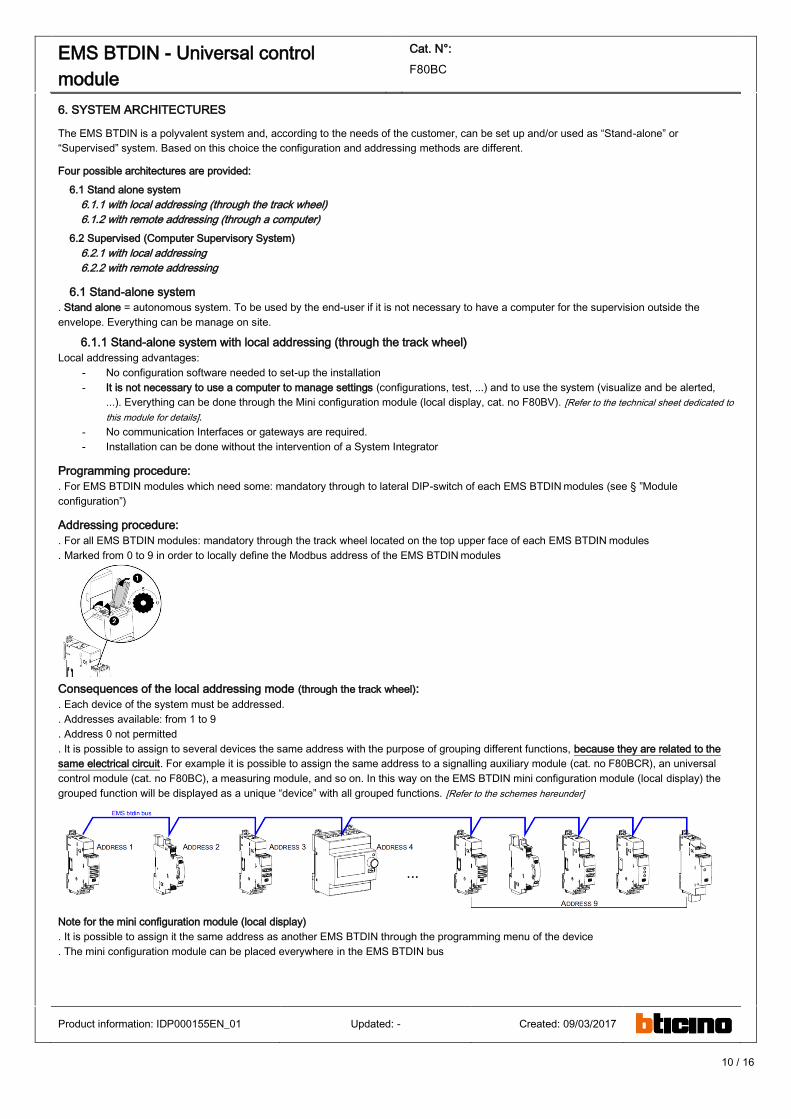
. For all EMS BTDIN modules: mandatory through the track wheel located on the top upper face of each EMS BTDIN modules
. Marked from 0 to 9 in order to locally define the Modbus address of the EMS BTDIN modules
Consequences of the local addressing mode (through the track wheel):
. Each device of the system must be addressed.
. Addresses available: from 1 to 9
. Address 0 not permitted
. It is possible to assign to several devices the same address with the purpose of grouping different functions, because they are related to the
same electrical circuit. For example it is possible to assign the same address to a signalling auxiliary module (cat. no F80BCR), an universal
control module (cat. no F80BC), a measuring module, and so on. In this way on the EMS BTDIN mini configuration module (local display) the
grouped function will be displayed as a unique “device” with all grouped functions. [Refer to the schemes hereunder]
Note for the mini configuration module (local display)
. It is possible to assign it the same address as another EMS BTDIN through the programming menu of the device
. The mini configuration module can be placed everywhere in the EMS BTDIN bus
Product information: IDP000155EN_01 Updated: - Created: 09/03/2017
11 / 16
EMS BTDIN - Universal control
module
Cat. N°:
F80BC
6. SYSTEM ARCHITECTURES
6.1 Stand-alone system (continued)
6.1.2 Stand-alone system with remote addressing (through a computer)
Remote addressing advantages:
- Whole configuration (addresses and functions) can be set up through the EMS Configuration software
- Configuration software available for free
- Automatic detection of the EMS BTDIN modules installed in the system (characteristics, functions, configuration...)
- Increased settings possibilities: load shedding function
- Increased addressing: up to 30 Modbus addresses in a system
Programming procedure:
. For EMS BTDIN modules which need some: possible through the lateral DIP-switch of each EMS BTDIN modules (see § “Module
configuration”).
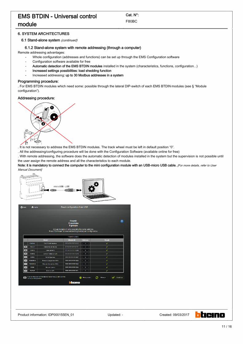
Addressing procedure:
. It is not necessary to address the EMS BTDIN modules. The track wheel must be left in default position “0”.
. All the addressing/configuring procedure will be done with the Configuration Software (available online for free)
. With remote addressing, the software does the automatic detection of modules installed in the system but the supervision is not possible until
the user assign the remote address and all the characteristics to each module.
Note: it is mandatory to connect the computer to the mini configuration module with an USB-micro USB cable. [For more details, refer to User
Manual Document]
Product information: IDP000155EN_01 Updated: - Created: 09/03/2017
12 / 16
EMS BTDIN - Universal control
module
Cat. N°:
F80BC
6. SYSTEM ARCHITECTURES
6.1 Stand-alone system (continued):
6.1.2 Stand-alone system with remote addressing (through a computer) (continued):
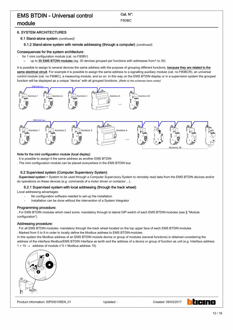
Consequences for the system architecture:
- for 1 mini configuration module (cat. no F80BV)
o up to 30 EMS BTDIN modules (eg. 30 devices grouped per functions with addresses from1 to 30)
It is possible to assign to several devices the same address with the purpose of grouping different functions, because they are related to the
same electrical circuit. For example it is possible to assign the same address to a signalling auxiliary module (cat. no F80BCR), an universal
control module (cat. no F80BC), a measuring module, and so on. In this way on the EMS BTDIN display or in a supervision system the grouped
function will be displayed as a unique “device” with all grouped functions. [Refer to the schemes here under]
Note for the mini configuration module (local display)
. It is possible to assign it the same address as another EMS BTDIN
. The mini configuration module can be placed everywhere in the EMS BTDIN bus
6.2 Supervised system (Computer Supervisory System)
. Supervised system = System to be used through a Computer Supervisory System to remotely read data from the EMS BTDIN devices and/or
do operations on these devices (e.g. commands of a motor driven or contactor ...).
6.2.1 Supervised system with local addressing (through the track wheel)
Local addressing advantages:
- No configuration software needed to set-up the installation
- Installation can be done without the intervention of a System Integrator
Programming procedure:
. For EMS BTDIN modules which need some: mandatory through to lateral DIP-switch of each EMS BTDIN modules (see § “Module
configuration”)
Addressing procedure:
. For all EMS BTDIN modules: mandatory through the track wheel located on the top upper face of each EMS BTDIN modules
. Marked from 0 to 9 in order to locally define the Modbus address to EMS BTDIN modules
In this system the Modbus address of an EMS BTDIN module device or group of modules (several functions) is obtained considering the
address of the interface Modbus/EMS BTDIN Interface as tenth and the address of a device or group of function as unit (e.g. Interface address
1 = 10 address of module n°5 = Modbus address 15)
Product information: IDP000155EN_01 Updated: - Created: 09/03/2017
13 / 16
EMS BTDIN - Universal control
module
Cat. N°:
F80BC
6. SYSTEM ARCHITECTURES (continued)
6.2 Supervised system (Computer Supervisory System) (continued)
6.2.1 Supervised system with local addressing (through the track wheel) (continued)
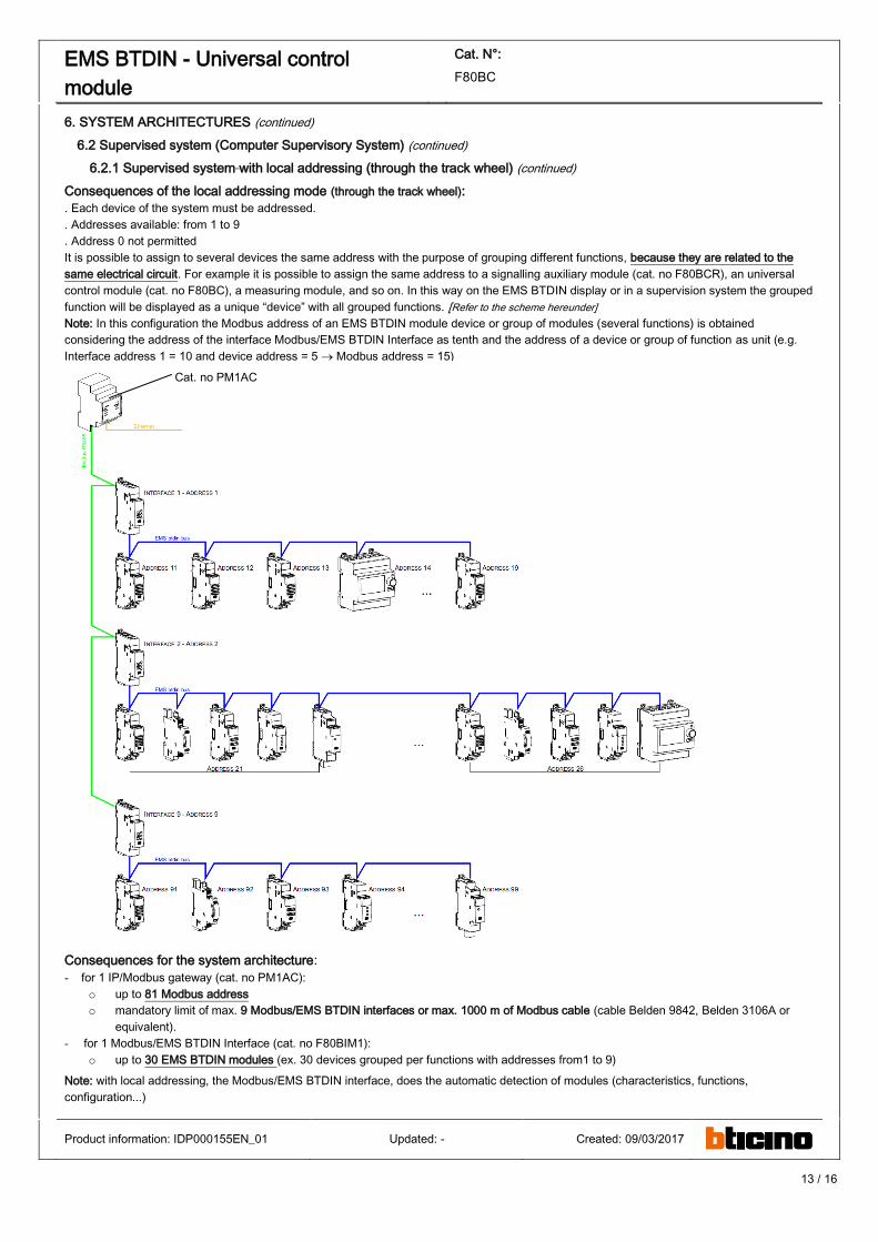
Consequences of the local addressing mode (through the track wheel):
. Each device of the system must be addressed.
. Addresses available: from 1 to 9
. Address 0 not permitted
It is possible to assign to several devices the same address with the purpose of grouping different functions, because they are related to the
same electrical circuit. For example it is possible to assign the same address to a signalling auxiliary module (cat. no F80BCR), an universal
control module (cat. no F80BC), a measuring module, and so on. In this way on the EMS BTDIN display or in a supervision system the grouped
function will be displayed as a unique “device” with all grouped functions. [Refer to the scheme hereunder]
Note: In this configuration the Modbus address of an EMS BTDIN module device or group of modules (several functions) is obtained
considering the address of the interface Modbus/EMS BTDIN Interface as tenth and the address of a device or group of function as unit (e.g.
Interface address 1 = 10 and device address = 5 Modbus address = 15)
Consequences for the system architecture:
- for 1 IP/Modbus gateway (cat. no PM1AC):
o up to 81 Modbus address
o mandatory limit of max. 9 Modbus/EMS BTDIN interfaces or max. 1000 m of Modbus cable (cable Belden 9842, Belden 3106A or
equivalent).
- for 1 Modbus/EMS BTDIN Interface (cat. no F80BIM1):
o up to 30 EMS BTDIN modules (ex. 30 devices grouped per functions with addresses from1 to 9)
Note: with local addressing, the Modbus/EMS BTDIN interface, does the automatic detection of modules (characteristics, functions,
configuration...)
Product information: IDP000155EN_01 Updated: - Created: 09/03/2017
Cat. no PM1AC
14 / 16
EMS BTDIN - Universal control
module
Cat. N°:
F80BC
6. SYSTEM ARCHITECTURES (continued)
6.2 Supervised system (Computer Supervisory System) (continued)
6.2.2 Supervised system with remote addressing (through a computer)
Remote addressing advantages:
- Whole of configuration (addresses and functions) can be done a remotely through the EMS Configuration software
- Configuration software available for free
- Automatic detection of the EMS BTDIN modules installed in the system (characteristics, functions, configuration...)
- Increased settings possibilities: load shedding function
- Increased addressing: up to 32 Modbus/EMS BTDIN interfaces
- Increased addressing: up to 247 Modbus addresses in a system
Programming procedure:
. For EMS BTDIN modules which need some : possible through the lateral DIP-switch of each EMS BTDIN modules (see § “Module
configuration”).
Note: via the configuration software it is possible to assign all the functions and characteristics of each EMS BTDIN module
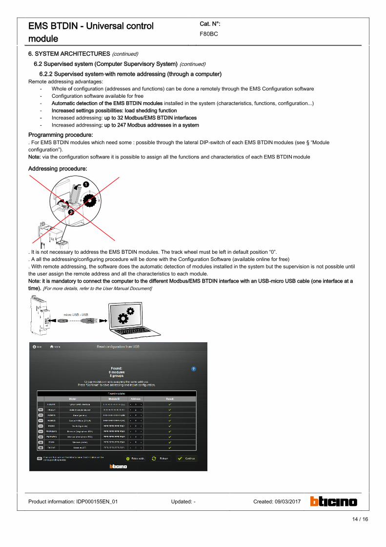
Addressing procedure:
. It is not necessary to address the EMS BTDIN modules. The track wheel must be left in default position “0”.
. A all the addressing/configuring procedure will be done with the Configuration Software (available online for free)
. With remote addressing, the software does the automatic detection of modules installed in the system but the supervision is not possible until
the user assign the remote address and all the characteristics to each module.
Note: it is mandatory to connect the computer to the different Modbus/EMS BTDIN interface with an USB-micro USB cable (one interface at a
time). [For more details, refer to the User Manual Document]
Product information: IDP000155EN_01 Updated: - Created: 09/03/2017
15 / 16
EMS BTDIN - Universal control
module
Cat. N°:
F80BC
6. SYSTEM ARCHITECTURES (continued)
6.2 Supervised system (Computer Supervisory System) (continued)
6.2.2 Supervised system with remote addressing (through a computer) (continued)
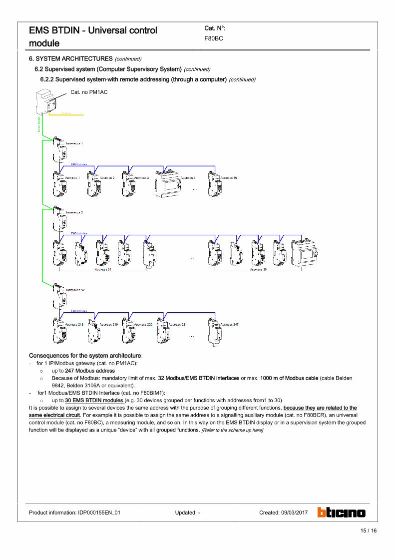
Consequences for the system architecture:
- for 1 IP/Modbus gateway (cat. no PM1AC):
o up to 247 Modbus address
o Because of Modbus: mandatory limit of max. 32 Modbus/EMS BTDIN interfaces or max. 1000 m of Modbus cable (cable Belden
9842, Belden 3106A or equivalent).
- for1 Modbus/EMS BTDIN Interface (cat. no F80BIM1):
o up to 30 EMS BTDIN modules (e.g. 30 devices grouped per functions with addresses from1 to 30)
It is possible to assign to several devices the same address with the purpose of grouping different functions, because they are related to the
same electrical circuit. For example it is possible to assign the same address to a signalling auxiliary module (cat. no F80BCR), an universal
control module (cat. no F80BC), a measuring module, and so on. In this way on the EMS BTDIN display or in a supervision system the grouped
function will be displayed as a unique “device” with all grouped functions. [Refer to the scheme up here]
Product information: IDP000155EN_01 Updated: - Created: 09/03/2017
Cat. no PM1AC
16 / 16
EMS BTDIN - Universal control
module
Cat. N°:
F80BC
7. COMPLIANCE AND APPROVALS
Compliance to standards:
. Compliance with Directive on electromagnetic compatibility (EMC)
n° 2014/30/EU
. Compliance with low voltage directive n° 2014/35/EU.
. Electromagnetic Compatibility:
IEC/EN 61131-2
IEC/EN 60947-5-1
Environment respect – Compliance with CEE directives:
. Compliance with Directive 2002/95/EC of 27/01/03 known as
"RoHS" which provides for a restriction on the use of dangerous
substances such as lead, mercury, cadmium, hexavalent chromium
and polybrominated biphenyl (PBB) and polybrominated diphenyl
ether (PBDE) brominated flame retardants from 1st July 2006
. Compliance with the Directive 91/338/EEC of 18/06/91 and decree
94-647 of 27/07/04.
. Compliant with regulation REACH
Plastic materials : . Halogens-free plastic materials.
. Marking of parts according to ISO 11469 and ISO 1043.
Packaging :
. Design and manufacture of packaging compliant to decree 98-638
of the 20/07/98 and also to directive 94/62/CE.
Environmental profile:
. PEP document available
Approvals obtained :
. See list of approvals available.
Product information: IDP000155EN_01 Updated: - Created: 09/03/2017