aspen plus/cosmo-rs multiscale ionic liquid conceptual
TRANSCRIPT
Universidad Autónoma de Madrid
Aspen Plus/COSMO-RS Multiscale Ionic Liquid Conceptual
Process Design.
Aromatic/Aliphatic Separation and CO2 Capture
Juan de Riva Silva
Dirigido por:
Dr. Víctor Ferro Fernández
Dr. José Palomar Herrero
Tesis Doctoral presentada para optar al grado de doctor por la
Universidad Autónoma de Madrid
Los profesores de la Sección Departamental de Ingeniería Química
(Departamento de Química Física Aplicada) de la Universidad Autónoma
de Madrid: D. Víctor Roberto Ferro Fernández y D. José Francisco
Palomar Herrero, CERTIFICAN:
Que la presente memoria “Aspen Plus/COSMO-RS Multiscale Ionic
Liquid Conceptual Process Design. Aromatic/Aliphatic Separation and
CO2 Capture” ha sido realizada bajo nuestra dirección en la Sección
Departamental de Ingeniería Química (Departamento de Química Física
Aplicada) de la Facultad de Ciencias de la Universidad Autónoma de
Madrid por D. Juan de Riva Silva y que constituye su tesis para optar al
grado de Doctor.
Y para que conste, firmamos la presente certificación en Madrid, a 1 de
noviembre de 2017.
Fdo: José Palomar Herrero Fdo: Víctor Ferro Fernández

A MI FAMILIA,
“THE GREATER THE OBSTACLE,
THE MORE GLORY IN OVERCOMING IT”
- Molière
Quiero comenzar estos agradecimientos por mis directores, Pepe
y Víctor; Víctor y Pepe. Gracias por formar el equipo de directores
perfecto, un equipo pragmático, pero con profundidad, metódico, pero
con la pizca de caos necesaria en ciencia. Víctor, me abriste la ventana a
mi pasión, me salvaste. Pepe, me brindaste oportunidades por las que
siempre te estaré agradecido. Gracias a ambos por enseñarme a pensar y a
escribir, por guiarme siendo flexibles y aceptando, cuando eran
razonables, mis propuestas. Representáis para mí la honradez, la pasión
por el trabajo, la capacidad de esfuerzo y la generosidad. Siempre seréis
mis referentes.
Gracias a Isa y a Lourdes, amigas y compañeras de sufrimientos, y
de alegrías. Por animarme a seguir cada vez que se presentaba un obstáculo
(y ha habido muchos). Sin vosotras habría tirado la toalla.
Gracias a mis compañeros de la Sección; siempre que os he
necesitado, habéis estado ahí. Gracias, en especial, a los integrantes del
grupo de líquidos iónicos de ahora y de siempre (Elia, María, Salama,
Jesús, Cristian, Daniel, Rubén, Marcos, Noelia y Jorge). Gracias a Cristian
por los Starbucks de mañana, los Taco Bell de mediodía, y los capítulos de
Juego de Tronos y las cervezas de noche, hiciste del “Midwest” un sitio
agradable. Si la estancia llega a durar más de tres meses no sé si nuestro
corazón habría sobrevivido con semejante estilo de vida.
Gracias a Rafa y a Miguel Ángel por su generosidad. A los
coautores de los trabajos en los que he participado y sin los que esta tesis
simplemente no existiría: Elia, José, Ismael, Daniel, Jorge, Manuel, Pablo,
Noemí, Juan José, Emilio… gracias. He aprendido algo de todos vosotros.
Gracias en especial a Elia, por poner el suelo sobre el que camino. A José,
porque es increíble que tanta inteligencia, capacidad de esfuerzo y
generosidad quepan en una misma persona. A Ismael, listo, generoso y
divertido; me lo he pasado siempre bien trabajando contigo y espero que
siga así en el futuro.
Gracias a mi familia, por apoyarme siempre. A mis padres, por
pelear por mi éxito, seguramente más que yo. Si esto significa algo, sois
dueños de buena parte de ello. A mis hermanos, por ser la fuerza
impulsora, os admiro y quiero muchísimo.
Gracias a Jessica. Porque contigo, puedo con todo. Gracias por
poner la sonrisa en mi vida.
La realización de la presente tesis ha sido posible gracias a la financiación
de Ministerio de Economía y Competitividad (MICINN) a través de los
proyectos CTQ2011-26758 y CTQ2014-52288-R, a la Comunidad de
Madrid a través de sus proyectos P2009/PPQ-1545 y P2013/MAE-2800,
así como al Proyecto de Cooperación Interuniversitaria UAM-Banco
Santander con EE.UU. de referencia 2015/EEUU/14
A
Table of Contents
Resumen ............................................................................................................. I
Abstract ........................................................................................................... VII
Introduction ....................................................................................................... 1
1.- Ionic Liquids ...................................................................................... 1
2.- Ionic Liquids in separation operations. .......................................... 6
2.1.- Ionic Liquids in extraction of Aromatic hydrocarbons from
Naphtha. .................................................................................................... 7
2.2.- Ionic Liquids in CO2 capture through physical or chemical
absorption. ................................................................................................. 9
3.- Molecular Modeling in IL design. ................................................. 12
4.- Process simulation of IL-involving processes. ............................ 15
5.- Multiscale approach for the conceptual development of industrial
processes based on ionic liquids ............................................................... 20
Chapter 1 .......................................................................................................... 25
1.- Introduction ..................................................................................... 26
2.- Computational Details .................................................................... 35
2.1.- Validating the property system created ............................... 35
B
2.2.- Process simulations ................................................................. 36
3.- Results and discussion .................................................................... 41
3.1.- Property prediction of pure ILs and their mixtures with the
organic compounds ................................................................................ 41
3.2.- Simulation of the extracting unit operation ........................ 48
3.3.- Simulation of the IL regeneration ......................................... 55
4.- General outlook ............................................................................... 62
5.- Concluding Remarks ...................................................................... 63
Chapter 2 .......................................................................................................... 69
1.- Introduction ..................................................................................... 70
2.- Computational Details .................................................................... 76
2.1.- Conceptual Process Designs .................................................. 76
2.2.- Design Specifications .............................................................. 79
2.3.- Separation Units Modeling .................................................... 80
2.4.- Sensitivity Analysis .................................................................. 81
3.- Results and Discussion ................................................................... 82
3.1.- Base Case Configuration ........................................................ 82
3.2.- Configuration 2 ....................................................................... 91
4.- Overview ........................................................................................... 95
C
5.- Conclusions ...................................................................................... 96
Chapter 3 ........................................................................................................ 101
1.- Introduction ................................................................................... 102
2.- Computational Details .................................................................. 107
2.1.- Process description ............................................................... 107
2.2.- Sensitivity analysis and optimization procedure .............. 110
3.- Results and discussion .................................................................. 111
3.1.- Phase equilibria modeling .................................................... 111
3.2.- Multicomponent extractive distillation simulation: low
aromatic content naphtha ................................................................... 114
3.3.- Multicomponent extractive distillation simulation: high
aromatic content naphtha ................................................................... 121
3.4.- Deviations of process simulations based on predictive
(COSMOSAC) data with respect to process simulations based on
fitted (NRTL) experimental data ........................................................ 125
4.- Conclusions .................................................................................... 128
Chapter 4 ........................................................................................................ 133
1.- Introduction ................................................................................... 134
2.- Computational Section ................................................................. 141
2.1.- Conceptual Process Design .................................................. 141
D
2.2.- CO2 Absorption Individual Operation ............................... 143
2.3.- IL Regeneration Individual Operation ............................... 144
2.4.- Complete Process .................................................................. 145
2.5.- Operating and Capital Cost ................................................. 146
3.- Results ............................................................................................. 147
3.1.- Validation of Property Estimations .................................... 147
3.2.- Absorption Individual Operation ....................................... 152
3.3.- Regeneration Individual Operation .................................... 156
3.4.- Complete Process .................................................................. 159
4.- Conclusions .................................................................................... 164
Chapter 5 ........................................................................................................ 169
1.- Introduction ................................................................................... 170
2.- Computational Details .................................................................. 175
2.1.- Component Definition and Thermodynamic Model
Specification .......................................................................................... 175
2.2.- Post-combustion CO2 Stream Characteristics. ................. 176
2.3.- Complete Process Design ..................................................... 177
2.4.- Absorption Individual Column ........................................... 179
2.5.- Regeneration Individual Column ....................................... 181
E
3.- Results ............................................................................................. 182
3.1.- Property Validation .............................................................. 182
3.2.- Absorption Individual Column ........................................... 186
3.3.- Regeneration Individual Column ....................................... 194
3.4.- Complete Process Results. ................................................... 196
4.- Concluding Remarks .................................................................... 199
Conclusiones y recomendaciones futuras .................................................. 203
Conclusions and future recommendations. .............................................. 207
Appendices ..................................................................................................... 213
1.- Chapter 2 Supporting information as in [163] .......................... 215
2.- Chapter 3 Supporting information as in [81] ............................ 220
3.- Chapter 4 Supporting information as in [84] ............................ 221
3.1.- Appendix A: ........................................................................... 221
3.2.- Appendix B: ............................................................................ 226
3.3.- Appendix C: ........................................................................... 231
5.- Chapter 5. Supporting information. ........................................... 240
List of Tables .................................................................................................. 241
List of Figures ................................................................................................. 245
References ....................................................................................................... 259

F
Publications related to this PhD Thesis ...................................................... 293
Other Publications ........................................................................................ 295

Resumen -----------------------------------
Abstract
Resumen /Abstract
I
Resumen
La tesis doctoral cuya memoria representa este documento se ha
desarrollado en la Sección de Ingeniería Química de la Universidad
Autónoma de Madrid en la línea de investigación de líquidos iónicos y
simulación liderada por los profesores Dr. José Palomar Herrero y Dr.
Víctor Ferro Fernández, que, desde 2007, ha venido estudiando los
líquidos iónicos desde diferentes perspectivas.
La formación del candidato a doctor se ha complementado con dos
estancias de investigación de 3 meses de duración en la Universidad de
Notre Dame, Indiana, Estados Unidos, bajo la supervisión de la profesora
Joan F. Brennecke, en las cuales se ha estudiado los procesos de captura de
CO2 por absorción química.
***
El uso de ILs constituye una de las posibles alternativas a los compuestos
orgánicos convencionales. Los ILs tienen propiedades excepcionales,
como son su baja volatilidad, su gran capacidad solvente y sus elevadas
estabilidades térmica y química. Además, una gran ventaja consiste en
que, mediante la modificación/permutación del catión y/o del anión se
pueden lograr miles o incluso decenas de miles ILs con diferentes
propiedades. Esto permite el diseño de sistemas de ILs con propiedades
optimizadas para tareas específicas. Sin embargo, muchos de ellos poseen
algunas propiedades indeseables que dificultan el desarrollo de estas
Aspen Plus/COSMO-RS Multiscale Ionic Liquid Conceptual Process Design .
II
aplicaciones a escala industrial. Algunas de las desventajas más destacables
son su alta viscosidad (que dificulta los fenómenos de transporte), la
elevada ecotoxicidad de algunos de ellos, los elevados precios tanto de los
ILs, como de algunas de las materias primas más utilizadas para su síntesis,
o la atomización de la comunidad científica en pequeñas comunidades que
estudian aplicaciones muy especializadas.
Para obtener mayor eficiencia en la investigación con ILs, una opción es
limitar, en la medida de lo posible, la cantidad de experimentación
necesaria desde la concepción de la posible aplicación hasta su escalado a
nivel industrial. Deben ser sólo los candidatos más apropiados a los que se
les dediquen, avanzado el proceso de investigación, recursos económicos
y personales en laboratorio, limitando los costes de dicha
experimentación. Esto implica conocer las propiedades termodinámicas
de los ILs y sus mezclas con todos los componentes del proceso sin la
necesidad de obtenerlas de forma experimental.
La combinación de simulaciones molecular y de proceso mediante la
utilización de la metodología multiescala desarrollada en el grupo de
líquidos iónicos y que dio lugar, en 2013, a la tesis doctoral de la Dra. Elia
Ruiz Pachón, permite incluir los ILs en los simuladores de proceso
comerciales de la suite de programas AspenOne. Durante la tesis cuya
memoria representa este documento, se amplió, desarrolló y aplicó esta
metodología al estudio de diferentes aplicaciones para las cuales los ILs
han sido ampliamente propuestos en bibliografía. Esto incluye:
Resumen /Abstract
III
• Selección de líquidos iónicos incluyendo criterios técnicos y
económicos.
• Análisis del comportamiento de disolventes a escala de procesos
con mezclas complejas multicomponente
• Diseño de operaciones unitarias: análisis de variables,
dimensionado de equipos comerciales, etc.
• Modelización de procesos completos: estimación de consumos
energéticos y de químicos, costes, optimización, etc.
• Análisis de viabilidad de los nuevos procesos basados en líquidos
iónicos por comparación con tecnologías convencionales.
***
En el capítulo 1, se estudian las operaciones individuales involucradas en
el proceso de extracción líquido-líquido de compuestos aromáticos
procedentes de nafta. Se estudia la regeneración del líquido iónico a través
de la destilación a vacío utilizando corrientes de mezcla multicomponente.
Se explora el uso de nueve ILs diferentes y sus mezclas, de binarias a
cuaternarias (líquido iónico - líquido iónico), como disolventes de
extracción. Se analizan los rendimientos de las operaciones individuales
en diferentes condiciones de operación, incluido el tipo de líquido iónico,
la relación disolvente / alimentación y la composición de la mezcla de
hidrocarburos.
Se demuestra la capacidad de las simulaciones de procesos basadas en la
metodología multiescala para tratar, con confianza, complejas mezclas
multicomponente de hidrocarburos y ILs. Se muestra, a su vez, la bondad
Aspen Plus/COSMO-RS Multiscale Ionic Liquid Conceptual Process Design .
IV
de esta metodología para simular con precisión operaciones unitarias con
consistencia matemática.
En el capítulo 2, utilizando el líquido iónico 4-metil-N-butilpiridinio
tetrafluoroborato ([4-mebupy][BF4]), se analizan y comparan dos
configuraciones de proceso diferentes propuestas en bibliografía con un
nuevo diseño de proceso, propuesto utilizando la metodología
multiescala. Se demuestra la capacidad de las simulaciones de procesos
basadas en COSMO para discriminar entre diferentes alternativas de
proceso mediante la realización de estimaciones razonables de costes de
capital y operativos.
En el capítulo 3 se desarrolla la ingeniería conceptual de un nuevo proceso
integrado de destilación extractiva propuesto para la separación de
compuestos aromáticos y alifáticos de nafta utilizando el líquido iónico 1-
etil-3-metilimidazolio dicianamida ([emim][DCA]) como agente de
arrastre. Se realiza un análisis de sensibilidad con 8,200 diseños diferentes
de columna de destilación extractiva variando la alimentación de líquido
iónico, la relación de reflujo, el número de etapas y la etapa de
alimentación, con el fin de optimizar el diseño de la columna
minimizando el calor del calderín y maximizando el rendimiento. Se
demuestra la capacidad de los líquidos iónicos para ser utilizados como
agentes en destilación extractiva de mezclas de aromáticos y alifáticos con
contenidos tan altos como un 90% de aromáticos. Se evalúa el
comportamiento del simulador de procesos utilizando COSMOSAC y el
modelo termodinámico clásico NRTL, regresionado a partir de datos
Resumen /Abstract
V
experimentales líquido-vapor y líquido-líquido. Se la coherencia de las
predicciones realizadas con la metodología multiescala.
En el capítulo 4, se evalúa el rendimiento de 8 ILs diferentes en la captura
de CO2 de postcombustión mediante absorción física en columnas
comerciales empacadas optimizando las condiciones de operación,
añadiendo criterios termodinámicos, cinéticos y técnicos a la selección del
líquido iónicos. Se estima la interdependencia de las variables y su
influencia en el costo operativo total (OPEX). Estos resultados se
comparan con resultados homólogos presentados en la literatura para
otras tecnologías de captura de CO2. Finalmente, se proporciona una
estimación preliminar del costo de capital (CAPEX) del proceso para una
planta piloto de tamaño cercano a la escala industrial. Se demuestra el
poder la herramienta integrada de simulación molecular y de proceso para
el diseño de operaciones unitarias de ILs y de procesos complejos con
elevado control cinético. Se añade dicho control cinético de transferencia
de masa de la operación de absorción de CO2 al conjunto de criterios de
selección de los ILs y se demuestra su elevada importancia en las
operaciones gas-líquido en las que los ILs están siendo propuestos como
alternativa a los compuestos orgánicos volátiles. Se demuestra la capacidad
de la metodología para simular columnas de separación comerciales
asistiendo en el diseño conceptual y los primeros pasos de la ingeniería
básica de procesos que involucran Ils.
Por último, en el capítulo 5, se simula, por primera vez utilizando la
metodología multiescala, un proceso con reacción química; la captura de
CO2 mediante líquidos iónicos de aniones heterocíclicos apróticos (AHA).

Aspen Plus/COSMO-RS Multiscale Ionic Liquid Conceptual Process Design .
VI
En este capítulo, se demuestra la capacidad de esta metodología para tener
en cuenta, de forma simultánea, fenómenos muy complejos, como la
cinética de la transferencia de materia, el equilibrio químico y el equilibrio
entre fases.
Resumen /Abstract
VII
Abstract
This PhD thesis has been carried out in the Chemical Engineering Section
of the Universidad Autónoma de Madrid, working in the ionic liquids
research line led by Professor Dr. José Palomar Herrero and Professor Dr.
Víctor Ferro Fernández, the group has been studying ionic liquids from
different perspectives since 2007.
The instruction of the PhD candidate has been complemented with two 3-
month research stays at the University of Notre Dame, Indiana, United
States, under the supervision of Professor Dr. Joan F. Brennecke, in which
the candidate studied CO2 capture processes by chemical absorption with
AHA ILs.
***
The use of ILs is one of the possible alternatives to conventional organic
compounds. ILs have exceptional properties, such as low volatility, high
solvent capacity and high thermal and chemical stability. In addition, by
modification/permutation of the cation and/or the anion, thousands or
even tens of thousands of ILs with different properties may be formed.
This allows the design of IL systems with optimized properties for specific
tasks. However, they have some undesirable properties that hinder the
development of these applications on an industrial scale. Some of the most
important disadvantages are their high viscosity (which hinders transport
phenomena), the high ecotoxicity some of them have, the high prices of
Aspen Plus/COSMO-RS Multiscale Ionic Liquid Conceptual Process Design .
VIII
both ILs, as well as some of the raw materials most commonly used for
their synthesis, or the atomization of the scientific community in small
groups that study very specialized applications.
To obtain greater efficiency in the IL research, one option is to limit, as far
as possible, the amount of experimentation needed from the conception
of the possible application to its industrial scale. Only the most
appropriate candidates, advanced the research process, should allocate
financial and personal resources, limiting the costs of such
experimentation. This implies knowing the thermodynamic properties of
the ILs, as well as the properties of their mixtures with all the components
involved in the process without the need to obtain this data
experimentally.
The combination of molecular and process simulations using the
multiscale methodology developed in the ionic liquids group of the
Chemical Engineering Section of the Universidad Autónoma de Madrid,
resulted, in 2013, in the doctoral thesis of Dr. Elia Ruiz Pachón. It allows
the implementation of ILs in commercial process simulators of the
AspenOne program suite. During the thesis whose memory represents
this document, this methodology was extended, further developed and
applied to the study of different applications for which the ILs have been
proposed in literature. This includes:
• The IL selection including technical and economic criteria.
• Analysis of the ILs’ behavior in industrial-scaled processes with
complex multicomponent mixtures
Resumen /Abstract
IX
• Unit operations design: variables analysis, commercial equipment
sizing and rating, etc.
• Modeling complete processes: Energy consumptions, operational
and capital costs, process optimization, etc.
• Feasibility analysis by comparison with conventional technologies.
***
In chapter 1 the individual operations involved in the liquid-liquid
extraction process of aromatics from naphtha are studied. The
regeneration of ILs is studied through vacuum distillation using
multicomponent “real” streams. The use of nine different ILs and their
mixtures, from binary to quaternary (ionic liquid - ionic liquid), are
explored as extraction solvents. The yields of the individual operations
under different operating conditions, including the type of IL, the
solvent/feed ratio and the composition of the hydrocarbon mixture, are
analyzed. The ability of multiscale-based process simulations (based,
therefore, on COSMO-type property prediction methods) to confidently
handle complex multicomponent mixtures of hydrocarbons and ILs is
demonstrated. It shows, additionally, the goodness of this methodology to
accurately simulate unit operations with mathematical consistency.
In Chapter 2, using the 4-methyl-N-butylpyridinium tetrafluoroborate
([4-mebupy][BF4]) IL, two different process configurations proposed in
literature are analyzed and compared with a new process design, proposed
using the multiscale, COSMO-based methodology. It demonstrates the
ability of this COSMO-based process simulations to discriminate between
Aspen Plus/COSMO-RS Multiscale Ionic Liquid Conceptual Process Design .
X
different process alternatives by making reasonable estimations of capital
and operating costs.
Chapter 3, the conceptual engineering of a new integrated extractive
distillation process proposed for the separation of aromatic and aliphatic
naphtha compounds using 1-ethyl-3-methylimidazolium dicyanamide
([emim] [DCA]) IL as entrainer, is carried out. A sensitivity analysis
including 8,200 different extractive distillation column designs is
performed varying the IL feed, the reflux ratio, the number of stages and
the feeding stage, to optimize the column design minimizing the reboiler
heat duty and maximizing the performance. The behavior of the process
simulator is evaluated using both the COSMOSAC thermodynamic model
and the classical NRTL property package, regressed from experimental
vapor-liquid and liquid-liquid data and, thus, demonstrates the
consistency of the predictions made with the multiscale methodology.
In Chapter 4, the performance of 8 different ILs in post-combustion CO2
capture by physical absorption in packed commercial columns is
evaluated optimizing operating conditions, while adding thermodynamic,
kinetic and technical criteria to the IL selection. The interdependence of
the variables and their influence on the total operating cost (OPEX) is
estimated. These results are then compared with homologous results
presented in the literature for other CO2 capture technologies. Finally, a
preliminary capital cost estimate (CAPEX) of the process is provided for
a near to industrial scale pilot plant. The power of the integrated molecular
and process simulation tool is demonstrated for the design of unitary
operations of ILs and complex processes with high mass transfer kinetic
Resumen /Abstract
XI
control. This mass transfer kinetic control of the CO2 absorption
operation is added to the IL selection criteria set and its high importance
is demonstrated in the gas-liquid operations in which ILs are being
proposed as an alternative to volatile organic compounds. It demonstrates
the ability of the methodology to simulate separations in commercial
columns, assisting the conceptual design and the first steps of the basic
engineering of processes involving ILs.
Finally, in Chapter 5, a process with chemical reaction is simulated, for the
first time, using the multiscale methodology: the CO2 capture by chemical
absorption using aprotic heterocyclic anions (AHA) ILs. In this chapter,
the ability of this methodology to consider, simultaneously, very complex
phenomena, such as mass transfer kinetics, chemical equilibrium and the
equilibrium between phases is demonstrated.

Introduction -----------------------------------
Introduction.
1
Introduction
1.- Ionic Liquids
Ionic liquids (ILs) are salts with low melting points made entirely of ions
[1]. Most of the ILs appearing in literature are liquid at room temperature
and are called Room Temperature Ionic Liquids (RTIL). The liquid state
is favorable due to the large size and flexibility of the ions, which leads to
small lattice enthalpies and large entropy changes [2]. ILs are formed by a
large organic cation and an organic or inorganic anion. Because of the vast
number of anions and cations that may form different ILs with different
chemical characteristics for different applications, they are considered
Designer Solvents [3].
In 1914 Paul Walden reported the physical properties of ethylammonium
nitrate (which melting point is 12 C) [4]. However, ILs did not draw
much attention from chemists till 1992, when Wilkes et. al., reported air-
and water-stable RTILs based on imidazolium salts. Subsequently,
research on the synthesis, properties, and applications of RTILs has
increased substantially [5]. The first industrial process involving ILs was
the BASIL™ (Biphasic Acid Scavenging utilizing Ionic Liquids) process [6].
This first commercial publicly announced process was introduced to the
BASF site in Ludwigshafen, Germany, in 2002. The BASIL™ process is used
to produce the generic photoinitiator precursor alkoxyphenylhosphines.
Eastman Chemical Company, however, was already running a process for
Aspen Plus/COSMO-RS Multiscale Ionic Liquid Conceptual Process Design .
2
the isomerization of 3,4-epoxybut-1-ene to 2,5-dihydrofuran since
December 1996 [7]. This was operated by the Texas Eastman Division, in
Longview until 2004.
ILs have received a lot of academic attention in the last years. Nowadays,
there is a high interest in researching new ILs and their industrial
applications. One of the main research driving forces in this field is the
benefit of substituting traditional industrial solvents with ILs. Even
though ILs are not fundamentally environmentally friendly (some of them
can be toxic), because of how easy they are to control in liquid phase (they
have very low vapor pressures) they are considered to have large potential
benefits for sustainable chemistry [3].
ILs have remarkable properties that confer significant potential for their
industrial application [8-17]. The main advantages of using a RTIL in
industrial processes are:
• Negligible vapor pressure.[8, 18, 19]
• Wide liquid window. Most of them near to room temperature and
all bellow 100 C (by definition) [20]
• High thermal & chemical stability [21-24]
• Good electrochemical properties, such as high stability to
oxidation/reductions [25-28]
Introduction.
3
• ILs are, generally, colorless and most of them are easy to handle.
• ILs can solvate a wide range of species, such as organic and
inorganic compounds, or gases (CO2, SO2, NH3, etc.) [29-38]
• ILs are considered “Designer Solvents” [3]. The systematic
premutation of the cation and the anion that form the IL, can be used to
“fine-tune” the properties of an IL making it suitable for a wide variety of
applications [5]. The choice of the anion and cation not only influences
the physical properties, but also, if used as solvent, the thermodynamics
and the reaction kinetics
ILs were firstly synthesized for electrochemical purposes [39]. They were,
afterwards, found useful as reaction media in chemical and biochemical
processes [40, 41]. Nowadays, the number of applications in which the ILs
are studied has expanded significantly [41, 42]: recovery of biofuels [43],
deep desulfurization of diesel oil [44], as lubricants [45], in solar cells [46-
48], for heat storage [49], in nuclear fuel processing [50], in membrane
technology [51-53], as sol-gel templates [41], and in the dilution of
cellulose [54]. ILs can be used as absorbents of refrigerants in absorption
refrigeration cycles [55-57]. They have been used as solvents for the
separation by extraction of multitude of components from different
process streams [43, 58, 59]. The use of ILs as extraction solvents in liquid-
liquid extraction of aromatic hydrocarbons from different aromatic-
containing Naphtha has been extensively studied in the last years [60-66].
The use of ILs as media for CO2 gas separations appears especially
Aspen Plus/COSMO-RS Multiscale Ionic Liquid Conceptual Process Design .
4
promising, as ILs can absorb physically and chemically high amounts of
CO2 [67-75]. These two last applications are the focus of this PhD thesis.
ILs have, however, some disadvantages that have limited the extension of
their application in industrial processes at large scale. Their complex
synthesis or the prohibitive cost of the raw materials make some ILs very
or even extremely expensive chemical compounds. The non-application
at large scale does not encourage the companies responsible of providing
ILs to produce them at large scales, fact that also contributes to their high
prices. From a thermophysical standpoint, their high viscosity (from 10 to
more than 105 cP) [76] is one of the most significant disadvantages.
However, the viscosity of ILs strongly depends on temperature, showing a
typical exponential decay behavior, reaching reasonable values at
temperatures frequently used in common industrial applications [77]. The
inability of characterizing the pure ILs due to the presence of impurities
and the general lack of experimental data limit, too, the industrial
application of ILs [78].
In addition, as already stated, ILs are composed by, at least, one anion and
one cation and there are hundreds of both components being, therefore,
it is possible to generate thousands of ILs by combination. This is one of
the main advantages of the ILs as it allows finding an optimum IL for many
different applications. However, some aspects of this huge amount of
possibly formed ILs have been, historically, a problem to the application
of ILs at an industrial level. Among this huge amount of different ILs,
identifying the optimum IL, i.e., selecting the IL for each application, is
difficult, based in the wide variety of families, behaviors and structures.
Introduction.
5
For instance, the careful selection of substituents on any of the positions
in the ring of imidazolium-based ILs and the exchange of the anion
influences many physical properties such as the melting point, boiling
point, and viscosity [79]. Experts in each application have made efforts in
the selection of the optimum IL for the application of study. In this sense,
the approaches when selecting the optimum IL are not homogeneous.
Some groups study ILs of the families most studied in literature in each of
the fields (divided by studied applications) and, according to the criteria
they deem appropriate (generally, thermodynamics),, select the IL or the
family of ILs that they will use in their studies. Other groups use the later
and do not contribute with additional information regarding to the IL
selection but provide new data, information or general knowledge of ILs
selected by others. In some cases, groups with a very deep background in
fundamental chemistry, apply their knowledge in this area in selecting or
even designing new ILs for the studied applications. This way, certain
families of ILs are more studied than others, for each application.
Imidazolium-based ILs are, for example, more used in applications such
as extractive agents for aromatic products [80-83], or as absorbents in CO2
capture [84-87] than others while phosphonium-based ILs are widely used
in electrochemical applications [88]. The size of the scientific
communities, experts in the study of each application, is, in some cases,
very small, narrowing the pursuit of new and better ILs. All in all, the
amount of different ILs, the inability of selecting the optimum IL for each
application, their price, and the size of some of the scientific communities
studying each field; make it difficult for the ILs to reach the industrial scale
or, in some cases, even advanced research.
Aspen Plus/COSMO-RS Multiscale Ionic Liquid Conceptual Process Design .
6
In this thesis, 4 years of work towards the development and identification
of tools able to design/select ILs for various applications in a more flexible
and universal manner and tools able to evaluate the suitability of the
selected ILs to reach the industrial scale are summarized.
2.- Ionic Liquids in separation operations.
ILs have gained popularity as ‘green’ alternatives to volatile organic
solvents (VOCs) to be applied in electrochemical, synthetic and separation
processes [89]. The physicochemical properties of ILs are influenced by
both their cationic and their anionic components. For example, both the
densities and surface tensions of ILs based on [Cnmim] cations with the
same anion decrease when the length of alkyl chain increases. In contrast,
the viscosities of the same group of ILs with the same anion increase with
an increase in alkyl chain length [90]. The solubility of ILs depends on
both the cation and anion. For example, 1-butyl-3-methylimidazolium
chloride ([bmim][Cl]) and 1-butyl-3-methylimidazolium
tetrafluoroborate [bmim][BF4] are soluble in water, while 1-butyl-3-
methylimidazolium hexafluorophosphate [bmim][PF6] and 1-butyl-3-
methylimidazolium bis(trifluoromethylsulfonyl)imide [bmim][NTf2] are
immiscible in water. Increasing the length of alkyl chain on the cation
lowers the solubility of ILs with [BF4] anions, for instance, the 1-octyl-3-
methylimidazolium tetrafluoroborate ([omim][BF4]) IL is immiscible
with water [91].
Introduction.
7
ILs have been widely employed in extractions, as GC stationary phases, in
supported liquid membranes, porous IL containing particles, as
absorbents and other separation processes, both in liquid phase and
supported in solids. In some cases, they can be considered “green”
solvents, but they have many other benefits including unusual selectivity,
high extraction efficiencies, dual-nature GC properties, durability, and
resistance to thermal degradations It should be noted that the
environmental benefits of ILs need be carefully considered. Recent work
demonstrated the toxicity of some ILs [92]. More research is also needed
on their long-term stability and recyclability.
2.1.- Ionic Liquids in extraction of Aromatic hydrocarbons from
Naphtha.
As a favorable separation technique, extraction is an energy-efficient
technology using two immiscible phases (conventionally an organic phase
and an aqueous phase). Many organic solvents involved, however, are
toxic and flammable VOCs. To improve the safety and environmental
friendliness of this conventional separation technique, ILs can be used as
ideal substitutes because of their stability, nonvolatility and adjustable
miscibility and polarity [93, 94].
Most ethylene crackers in oil refineries contain between 10 and 25% of
aromatic hydrocarbons. During the cracking process, the aromatic
compounds are not converted to olefins [64]. Therefore, there is between
10 and 25% of the stream to be treated occupying an important part of the
Aspen Plus/COSMO-RS Multiscale Ionic Liquid Conceptual Process Design .
8
capacity of the furnaces that will accompany the C5+ fraction and, in
addition, will complicate their separation representing extra operating
costs for the plant. The part of the process in which the aromatic
compounds are present is oversized and the equipment in this section
have greater energy consumption (especially important in the furnace
located at the entrance of the process). If the aromatic hydrocarbons are
captured before the ethylene crackers, both the operating and capital costs
would be reduced. According to an economic study [64], the potential
savings attainable by the elimination of aromatics at the entrance of
naphtha crackers is 20€/t, approximately 48M€/year in a plant treating 300
t/h. of naphtha.
The separation of aromatic hydrocarbons from aliphatics of 4 to 10 carbon
atoms is complex since the compounds involved have boiling
temperatures very close to each other and several azeotropic mixtures may
be formed. Conventional processes used to separate aromatic
hydrocarbons from naphtha depend on the aromatic content. The liquid-
liquid extraction separation is suitable for the range of 20-65% by weight
using traditional organic compounds (sulfolane, n-methylpyrrolidone, n-
formylmorpholine, ethylene glycol, propylene carbonate and others as the
solvent [95, 96]. Because the most commonly proposed conventional
solvent, sulfolane, cannot be used to separate aromatic hydrocarbons from
low- ore very low- aromatic containing Naphtha, ILs are considered a very
promising alternative for performing this separation [60, 64, 97].
Low-viscosity cyano-containing ILs have been proposed for the aromatic
extraction of aromatic compounds from high aliphatic containing
Introduction.
9
naphtha [24, 98]. In addition, mixtures of mutually miscible ILs [99, 100]
and even immiscible [101] ILs have been studied to improve the extracting
properties in respect to the individual ILs.
The separation of aromatic hydrocarbons from naphtha with ILs is a very
attractive process for this PhD thesis: i) the thermophysical properties of
many ILs selected as possible candidates for performing this separation
have been experimentally measured, ii) the liquid-liquid and, in a minor
extent, the vapor-liquid equilibria of many ternary/binary systems are
available in literature [66, 101-103] iii) process developments [64, 97, 104],
including pilot plant scaled experiments [105] have been carried out but
for a limited number of ILs. Having that amount of experimental and
theoretical work is of extreme importance for the development of new
tools able to predict both thermophysical and process data, as it can be
used for validation purposes. In all the literature available, the conceptual
designs (despite their complexity) developed so far for this process [64, 97,
106-109], at least two operations are considered i) liquid-liquid extraction
using ILs as extracting solvents and, ii) IL regeneration by vacuum
distillation. Stripping with air has also been proposed as an alternative to
IL regeneration [66, 104].
2.2.- Ionic Liquids in CO2 capture through physical or chemical
absorption.
In the absorption of gases, a soluble vapor is absorbed from its mixture
with an inert gas by means of a liquid in which the gas (solute) is more
Aspen Plus/COSMO-RS Multiscale Ionic Liquid Conceptual Process Design .
10
soluble or react chemically with the gaseous solute. A prime application of
the absorption technology is the removal of CO2 and H2S from natural gas
or syngas by absorption in solutions of amine or alkaline salts. Washing
ammonia from a mixture of ammonia and air by water is another typical
example. The solute is recovered after by distillation, and the absorbent is
either reused. Sometimes a solute is removed from a liquid by placing the
latter in contact with an inert gas; such an operation, which is inverse to
absorption, is called desorption of gases [110]. Both operations are present
in the CO2 capture since, in a first operation, the CO2 is absorbed into the
liquid absorbent while, afterwards, the CO2 is desorbed from the
absorbent by pressure or temperature swing, frequently using an
additional stripping stream.
Currently, there is a growing consensus on the contribution of
anthropogenic CO2 emissions to climate change, with combustion power
plants being a major source of emissions. Available post-combustion CO2
capture technologies utilize corrosive amine solutions with high operating
costs and high environmental impact, associated with the loss of solvent
by evaporation or degradation, corrosion and high energy consumption
of the regeneration. It is, therefore, critical to develop innovative
technologies for CO2 capture that promote safer, cleaner and more
efficient use of fossil fuels. In fact, many separation processes are being
investigated for the CO2 retention, including liquid absorption, solids
adsorption or membrane separation [111]. This effort is not only aimed to
improve available technologies but also to develop new conceptual process
designs. In this sense, ILs are receiving great attention as solvents for CO2
capture through both physical and chemical absorption processes [112].
Introduction.
11
Nowadays, ILs are being intensively investigated as absorbents in gas
separation processes [113], due to their excellent properties, among which
we can highlight an almost zero volatility (which minimizes emissions),
high thermal and chemical stability, and high solvent capacity. The
application of ILs as CO2 absorbents has been the subject of a growing
number of investigations (> 400 publications in the last 5 years), focusing
efforts on optimizing the properties of ILs as solvents alternative to the
amines used in the conventional processes [112]. Some works show that
the nature of the cation and the anion determines both the
thermodynamic and kinetic properties of the physical absorption of CO2
in the ILs [114, 115], so both aspects should be considered when designing
an appropriate ILs-based capture system [115]. Recently, even mixtures of
ILs [116, 117] have been proposed as an alternative to modulate the
properties of the absorbent, combining ILs that contribute with high
absorption capacities and with ILs that improve the transport properties
of the mixture. Also, different type of ILs present chemical reaction with
CO2, which entails significantly higher capture capacities, among which
are ILs with acetate anions [118], anions or cations functionalized with
amines [119] or reversible ILs [120-122] and ILs based on aprotic
heterocyclic anions (AHA) [85, 123-125]. The latter, were developed in
the University of Notre Dame, where the PhD candidate spent 5 months
as invited researcher.
The absorption of CO2, like the aromatic extraction from naphtha, has
many advantages for the purposes of this PhD thesis. i) it has been widely
studied so both the thermophysical properties and the CO2-IL gas-liquid
Aspen Plus/COSMO-RS Multiscale Ionic Liquid Conceptual Process Design .
12
equilibrium of the systems are, in general, available in literature and may
be used for validation purposes; ii) some process designs have been
developed using commercial or custom process simulation tools [126]
both for the simulation of physical and chemical absorptions; and iii)
lastly, being a gas-liquid separation process, the mass transfer kinetic
control of the operation may be greater than in the more homogeneous
liquid-liquid aromatic-aliphatic extraction. This would allow us to test the
simulation procedure in commercial equipment and would allow to
introduce new criteria in the design/selection of ILs for mass transfer
kinetic controlled gas-liquid operations. Furthermore, and thanks to the
collaborations with Prof. J. Brennecke’s group of the University of Notre
Dame, this study would be extended to chemical absorptions.
3.- Molecular Modeling in IL design.
In the last decade, with the previously described increase in the number of
studied applications involving ILs, there has been a continuous progress
in the experimental determination of thermophysical properties of ILs and
their mixtures with various solutes and gases. This information is
compiled in databases such as the IUPAC Ionic Liquid database [127] or
the Dortmund Databank [128] (DDBSP GmbH, 1989). These databases
provide up-to-date information on ILs publications with over 520,000 and
320,000 total data points, respectively, as of October 2017. However, the
cost of the ILs and the vast number of different ILs that may be formed by
permutation of the anion and the cation presents a deficiency in the
Introduction.
13
information available for those systems that are not usually studied for
common industrial applications.
The cation and anion selection among the vast amount of possible
combinations is, indeed, a key aspect of the research with ILs [129]. The
development of an efficient predictive method able to predict
thermophysical properties of ILs and their mixtures could be helpful to
reduce the amount of experimentation needed [130]. In this sense,
molecular dynamic simulations (MD) [131], quantitative structure
property relationship (QSPR) [132-135] or more classical models such as
UNIFAC [136, 137] have been helpful when estimating the properties of
ILs. Supported by predictive methods, different computational
approaches [138-141] have been developed to design new ILs with specific
properties. This means that cation and anion are combined in such a way
the properties of the IL are optimized for a specific application. However,
most of the parameters of these models must be regressed from
experimental data making them, ultimately, laboratory dependent. The
quantum chemistry based on the COnductor-like Screening MOdel for
Real Solvent (COSMO-RS) have been an attractive predictive way of filling
this need as it can perform predictions from a pure a priori standpoint
[142]. This type of methodologies has started to be applied to areas
classically covered by chemical engineering in the last years giving
computational tools to researchers and process engineers.
The ILs group of the Chemical Engineering Section of the Universidad
Autónoma de Madrid has a deep and extensive background in the
application of a priori theoretical methods for both the thermophysical
Aspen Plus/COSMO-RS Multiscale Ionic Liquid Conceptual Process Design .
14
properties of ILs and in the application of such methods in the IL design
and selection. In this sense, in 2007, a quantum-chemical computational
approach to accurately predict the nuclear magnetic resonance (NMR)
properties of 1-alkyl-3-methylimidazolium IL was performed by the
gauge-including atomic orbitals method at the B3LYP/6-31++G** level
using different simulated IL environments. In this work, the ion pair (CA)
and separated ions (C+A) models to represent the chemical structure of
ILs were introduced. In addition, the solute-solvent interaction nature was
correlated to the calculated NMR properties [143]. In a later work,
through the collaboration of this group with Prof. Somolinos’s group of
the Universidad Complutense de Madrid, the density and molar liquid
volume of 40 imidazolium-based ILs was predicted using the COSMO-RS
method. Because of the analysis, the charge distribution area (� -profile)
was proposed as an a priori parameter to characterize the contributions of
the cation and anion to the IL behavior for the solvent design [144]. The
development of Neural Networks using these COSMO-RS descriptors
was, afterwards, used for the IL design, deepening in the idea of using
methods capable of predicting thermophysical properties of ILs for their
design without the massive use of experimental data [140, 144]
Afterwards, the group started using this prediction methods not only for
the prediction of thermophysical properties of ILs but to the selection of
optimized ILs for specific applications. From ILs for the CO2 capture [114,
145-147], the detection of the cytotoxicity of ILs [148], the ammonia
absorption[35, 149, 150], solution of lignin and cellulose [151], the
recovery of ILs from water solutions [152] and many other applications
Introduction.
15
[145, 147, 153, 154], while continuing developing and making more deep
analysis of fundamental properties using those a priori methodologies.
4.- Process simulation of IL-involving processes.
Process simulation could also be helpful to avoid some experimental work
for the development of new applications involving ILs as it is for the
development of other processes and products. Calculations, prototypes,
and analysis are all tools that provide guidance to engineers as the design
moves through the design cycle [155, 156]. The operating conditions,
equipment sizing, operational and capital costs, performance or even the
feasibility of a process can be analyzed by process simulation. Specialized
simulation software describes processes in flow diagrams where unit
operations are positioned and connected by component streams. It is a
model-based representation of chemical processes and unit operations in
software. However, to perform process simulations, the knowledge of
chemical and physical properties of pure components and mixtures
involved is a prerequisite that allow the calculation of the process. In
addition, the mathematical relations between phases or the controlling
thermodynamic, kinetic and reaction phenomena need to be described
accurately. In ordinary simulations, these physicochemical properties and
mathematical relations are stored into large compound and property
model databases within the process simulator. ILs, however, are not
conventionally included in the databases of the commercial process
simulators. On the other hand, most of the property models present in the
process simulators’ databases are, in summary, based on the fitting of
Aspen Plus/COSMO-RS Multiscale Ionic Liquid Conceptual Process Design .
16
experimental data, which is scarce or, in the best-case scenario,
insufficient, if mixtures of compounds containing ILs want to be
calculated. There are, basically, three different alternatives to incorporate
ILs into commercial process simulators, which in turn require three
different thermodynamic methods to predict the interactions between ILs
and the rest of the process components, their in-mixture phase behavior
and any other activity coefficient or fugacity related property.
1. As a conventional component [20]. Simulators give the user the
possibility to include new components. To do this, all the properties of the
pure component must be included. Boiling temperatures, molar volumes,
densities, molecular weights, vaporization enthalpies and many other
properties of the pure component must be included in addition to their
corresponding behavior as a function of temperature.
The behavior of mixtures of ILs with other components is modeled by
regression from experimental data of binary interaction parameters of
common thermodynamic models (NRTL, UNIQUAQ ...). Although this
methodology has as main advantage the precision of its modeling (since it
may be said that the stream variables are rather interpolated than
calculated), it is necessary to collect or produce the experimental data
required. Given the substantial number of existing ILs, their price, and, in
some cases the extreme difficulty of obtaining these properties (like, for
example, the normal boiling temperature) having all this information is
unviable for ILs selection and design. Even in the case where this
experimental data may be collected or produced, the representation of
multicomponent mixtures would be of great difficulty since these
Introduction.
17
thermodynamic models would need parameters for all the pairs of
components present in the mixture to operate with guarantees, making
the mathematical problem exponentially more complicated when adding
new components to the system. Furthermore, the inclusion of hundreds
of properties and parameters into the process simulator lead, frequently,
to very difficult to detect mathematical incongruences that produce
convergence errors and simulation crashes. Bagchi et al., [157] for
instance, use Peng-Robinson equation of state with quadratic van der
Waals (vdW) mixing rule model to perform the thermodynamic
calculations in the Aspen Plus FLASH3 column of to calculate the
solubility of CO2 and other hydrocarbons (HCs) among methane, ethane,
propane, and butane in the IL 1-ethyl-3-methylimidazoliumtris
(pentafluoroethyl) trifluorophosphate ([emim][FAP]). Bubble point
pressure, solubility, bubble point temperature, fugacity, and partial molar
volume at infinite dilution were obtained from the simulations, and
enthalpy of absorption, Gibbs free energy of solvation, and entropy change
of absorption were estimated by thermodynamic relations. These results,
even accurate according to the authors, are limited to a single unit
operation and binary mixtures.
2. Group Contribution Methods (GCM) for the estimation of the
properties of the pure component and its mixtures. The most commonly
present GCM in the process simulators’ thermodynamic model databases
is UNIFAC (UNIQUAC Functional-group Activity Coefficients) [158]. It
is a semi-empirical thermodynamic model for the prediction of non-
electrolyte activity in non-ideal mixtures. UNIFAC uses the functional
groups present on the molecules that make up the liquid mixture to
Aspen Plus/COSMO-RS Multiscale Ionic Liquid Conceptual Process Design .
18
calculate activity coefficients. By using interactions for each of the
functional groups present on the molecules, as well as some binary
interaction coefficients, the activity of each of the solutions can be
calculated. The UNIFAC method has recently been modified and
expanded to include as functional groups the anions and cations forming
ILs [159]. The main advantage of this methodology is the flexibility in the
use of a variety of cations and anions, however, UNIFAC groups must be
parameterized, this may be sometimes complicated as choosing which
part or if even the entire ion will constitute a UNIFAC group may have
very important consequences both in the accuracy of the estimations and
the width of the applicability of the method. This way, introducing new
ILs with complex interactions between cation and anion or even within
the ions may be difficult or would, at least, require expanding the number
of UNIFAC groups which is contradictory with the general purpose of the
method. Zhu et al, [160] for example, study the feasibility of IL-extractive
distillation using process simulations using a UNIFAC modified
thermodynamic model (UNIFAC-Lei) for the separation of ethyl acetate
and ethanol in Aspen Plus using four different ILs (1-ethyl-3-
methylimidazolium methanesulfonate [emim][MeSO3], 1-ethyl-3-
methylimidazolium methylsulfate [emim][MeSO4], 1-butyl-3-
methylimidazolium trifluoromethanesulfonate [bmim][CF3SO3] and 1-
ethyl-3-methylimidazolium tetrafluoroborate [emim][BF4]). The whole
extractive distillation process including solvent recovery system of a flash
tank and a stripper was conducted in Aspen Plus. In order to perform such
simulations, methylimidazolium methanesulfonate [mim][MeSO3],
methylimidazolium methylsulfate [mim][MeSO4], methylimidazolium
trifluoromethanesulfonate [mim][CF3SO3], methylimidazolium
Introduction.
19
tetrafluoroborate [mim][BF4] (plus the basic included UNIFAC groups;
CH3, CH2, OH and CH3COO) need to be defined as UNIFAC groups. To
simulate the separation of 2 conventional compounds (ethyl acetate and
ethanol) with 4 different ILs 32 interaction parameters were used. As
explained by the authors “If the necessary binary group interaction
parameters exist for every pair of functional groups of the mixture,
UNIFAC-Lei model is worthy”. However, including new ILs or simply
considering the simulation of existing ILs not present in such databases is
of extreme difficult.
3. Including information of the pure ILs and their behavior in
mixture with the rest of the compounds of the studied process using
information from a priori methods such as COSMO (CO-inductor-like
Screaming MOdel). This approach, thanks to its a priori character, broads
the flexibility of the simulations when calculating processes involving
multicomponent systems. The ILs can be included in the process
simulator specifying them as pseudo-components. This alternative follows
the same direction as the GCM but with more fundamental arguments
from a theoretical point of view. The thermodynamic behavior of the
mixture is governed by the specification of the COSMO-based model as
implemented in the process simulator property system. With very little
parameterization, based only on the molecular structure of the
compounds, this type of models has advantages in terms not only of
flexibility but in terms of theoretical and mathematical consistency.
The ILs group of the Chemical Engineering Section of the Universidad de
Madrid was pioneer in the use of such method. This multiscale (with
Aspen Plus/COSMO-RS Multiscale Ionic Liquid Conceptual Process Design .
20
molecular, mesoscale and process information) approach for the inclusion
of ILs as components in the Aspen Technology’s Aspen Plus process
simulator was developed in our group. For further and more detailed
information about this methodology, please refer to Dr. Elia Ruiz Pachón’s
PhD thesis [161].
We have applied this multiscale methodology to the study of the toluene
absorption with ILs [162], the regeneration of IL by vacuum distillation
[153] the absorption refrigeration cycles using ILs as absorbents [56, 57],
the separation of aromatic-aliphatic hydrocarbon compounds using ILs
[80, 81, 163] and the CO2 capture both by physical and chemical
absorption [84, 164]. It must be emphasized that, in the last few years, the
application of this methodology is starting to surpass our group [165, 166].
In the next section, the methodology is briefly summarized.
5.- Multiscale approach for the conceptual development of
industrial processes based on ionic liquids
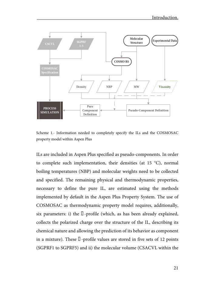
The multiscale tool for the conceptual development of industrial ionic
liquids involving processes allows the implementation of ILs as
components in Aspentech’s commercial process simulators. In Scheme 1
all the information needed to completely specify ILs and the COSMOSAC
property model into the process simulators and the sources of such
information is presented.
Introduction.
21
Molecular Structure
MW
Pseudo-Component Definition
Experimental Data
COSMO RS
ViscosityDensity NBP
CSCVL SGPRF1-5
Pure ComponentDefinition
COSMOSACSpecification
PROCESSSIMULATION
Scheme 1.- Information needed to completely specify the ILs and the COSMOSAC property model within Aspen Plus
ILs are included in Aspen Plus specified as pseudo-components. In order
to complete such implementation, their densities (at 15 C), normal
boiling temperatures (NBP) and molecular weights need to be collected
and specified. The remaining physical and thermodynamic properties,
necessary to define the pure IL, are estimated using the methods
implemented by default in the Aspen Plus Property System. The use of
COSMOSAC as thermodynamic property model requires, additionally,
six parameters: i) the � -profile (which, as has been already explained,
collects the polarized charge over the structure of the IL, describing its
chemical nature and allowing the prediction of its behavior as component
in a mixture). These � -profile values are stored in five sets of 12 points
(SGPRF1 to SGPRF5) and ii) the molecular volume (CSACVL within the

Aspen Plus/COSMO-RS Multiscale Ionic Liquid Conceptual Process Design .
22
Aspen Property System). In the years of conducting this PhD thesis, the
experimental viscosity-to-temperature dependence of the ILs has been
also included when implementing ILs in the process simulators, since it
allows the calculation of mass transfer kinetic controlled and transport
operations.
The molecular geometries of the ionic (CA) pairs are optimized at the
BP86/TZVP computational level considering solvent interactions through
the COSMO continuum solvation method. From the set of optimized
structures, the conformer with the lowest electronic energy (the most
stable) is selected. The quantum-chemical calculations are carried out
using TurbomoleX 4.2.1 [167]. COSMOthermX program package version
C30_1201 [168] with BP_TZVP_C30_1201 default parametrization is
used, afterwards, to perform the COSMO-RS calculations, obtaining the
required normal boiling points, densities, molecular volumes and the � -
profiles.
The viscosities are obtained from experimental data and included
regressing the two first parameters of the Andrade model (MULAND01
and MULAND02). The procedure of how this data is collected, statistically
refined and fitted is available in de Riva et. al 2014 [77].
Chapter 1 Conceptual design of unit operations to separate aromatic
hydrocarbons from naphtha using ionic liquids. COSMO-
based process simulations with multi-component “real”
mixture feed
Chapter 1.
25
Chapter 1
Conceptual design of unit operations to separate aromatic
hydrocarbons from naphtha using ionic liquids. COSMO-based
process simulations with multi-component “real” mixture feed
Abstract
COSMO-based process simulations using Aspen Plus and Aspen HYSYS
were systematically applied to the conceptual design of the two main unit
operations commonly proposed to separate aromatic and aliphatic
hydrocarbons with ionic liquids as extracting solvents; the proper
extraction and the vacuum distillation for regenerating the ionic liquid. By
the first time, multi-component “real” mixture feeds were taken into
account in the design. Binary model (n-hexane/benzene, n-
heptane/toluene, n-octane/ethylbenzene, n-octane/m-xylene) mixture
feeds were also considered to validate the computational procedure. Nine
different ionic liquids and their binary to quaternary (ionic liquid - ionic
liquid) mixtures were selected as extracting solvents. Ionic liquids were
introduced in the process simulations as pseudo-components. The
information needed to both create the non-data bank ionic liquid
(pseudo)components and to specify the COSMOSAC property model was
gathered from COSMO-RS calculations. COSMO-based models exhibited
a reasonably good predictability of both the thermo-physical properties of
the pure (hydrocarbons and ionic liquids) components and the LL and VL
equilibria of their mixtures. The performances of extraction and
Aspen Plus/COSMO-RS Multiscale Ionic Liquid Conceptual Process Design .
26
regeneration individual operations were analyzed at different operating
conditions, including the type of IL, the solvent/feed ratio, and the
hydrocarbon mixture composition. The present results suggest that
COSMO-supported process simulations are capable of confidently dealing
with complex multicomponent mixtures of hydrocarbons and ionic
liquids. This opens new perspectives to improved developments of this
process based on ionic liquids.
1.- Introduction
Separation of aromatic and aliphatic compounds from petrochemical
feedstocks, having a relevant economical and practical interest [64, 66], is
probably one of the most extensively studied separation processes using
ionic liquids (ILs) as an alternative to organic solvents. The conventional
processes used to remove the aromatics from naphtha depend on the
aromatics content being the extraction suitable for the range of 20-65 wt%
[64, 66]. Several polar organic solvents and mixtures of them have been
evaluated as possible extracting agents in this process: sulfolane, N-methyl
pyrrolidone, N-formyl morpholine, ethylene glycols, propylene
carbonate, furfural and others [95, 169, 170] but sulfolane, as a rule,
exhibits higher performances than the remaining organic solvents
evaluated. Hence, UOP has developed an industrial process to separate
aromatics from naphtha using this solvent [171]. Nevertheless, extraction
with conventional organic solvents (including sulfolane) seems not to be
a definitive option since additional separation operations are required to
separate the extraction solvent from both the extract and the raffinate
Chapter 1.
27
phases and to purify the solvent, resulting in additional investments and
energy consumption [64, 66]. Application of ILs as solvents for extraction
operations in the current and other industrial processes is widely accepted
as promising since, due to their negligible vapor pressure, it is expected to
require fewer process steps and less energy consumption than extraction
with conventional solvents. In particular, solvent recovery seems to be
relatively easy [64, 66]. Several ILs have been investigated as extracting
solvents in this process: imidazolium, pyridinium, pyrrolidinium, etc. A
complete review of the ILs investigated in this role over the past 10 years
can be found in [66].
More recently, low-viscous ILs based on the cyano-anions have been
proposed for the aromatic extraction [24, 98]. In addition, mixtures of
mutually miscible [99, 100] and even immiscible [101] ILs have also been
studied in order to improve the extracting properties in respect to the
individual ILs. Separation of aromatic compounds from naphtha with ILs
has been the subject not only of basic thermodynamic studies devoted to
elucidating the equilibrium conditions of the process (see for example ref.
[60-62, 66, 101-103, 106, 172-179] and references therein), but also of
process developments [64, 104, 180] including pilot plant scaled
experiments [104, 105]. In all the conceptual designs (in spite of their
complexities) developed so far for this and other similar processes [64,
104, 106-109, 180-182] two main operations are considered (Figure 1.1):
(i)- aromatic hydrocarbons are separated from their mixtures with
aliphatic ones by liquid-liquid extraction using ILs as extracting solvents
and, (ii)- further, ILs are regenerated from their mixtures with the
aromatic hydrocarbons (to be recycled at the beginning of the process) by
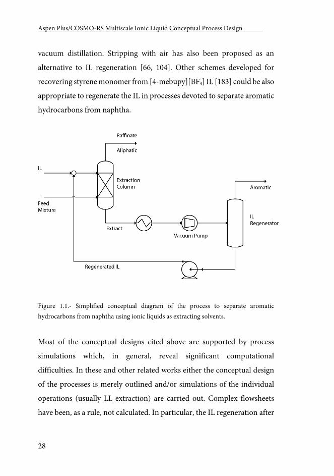
Aspen Plus/COSMO-RS Multiscale Ionic Liquid Conceptual Process Design .
28
vacuum distillation. Stripping with air has also been proposed as an
alternative to IL regeneration [66, 104]. Other schemes developed for
recovering styrene monomer from [4-mebupy][BF4] IL [183] could be also
appropriate to regenerate the IL in processes devoted to separate aromatic
hydrocarbons from naphtha.
Figure 1.1.- Simplified conceptual diagram of the process to separate aromatic hydrocarbons from naphtha using ionic liquids as extracting solvents.
Most of the conceptual designs cited above are supported by process
simulations which, in general, reveal significant computational
difficulties. In these and other related works either the conceptual design
of the processes is merely outlined and/or simulations of the individual
operations (usually LL-extraction) are carried out. Complex flowsheets
have been, as a rule, not calculated. In particular, the IL regeneration after
Chapter 1.
29
the primary separation with ILs is not simulated or simply mass balances
are performed specifying the IL recovery but without solving the phase
equilibrium for the corresponding VL operation. Only a few works
simulate the IL regeneration with one-stage VL separators, shortcut or
rigorous distillation columns [106-109, 181-183]. Regarding the
conceptual designs and the corresponding process simulations of the
aromatic separation from naphtha, another distinctive feature should be
emphasized: they are habitually limited to the use of binary (aromatic +
aliphatic) mixtures to model the real feed. Multi-component more “real”
mixtures are not considered. The most frequent difficulties found in
process simulations with ILs in general and in this process, are related to
severe errors occurring in the flowsheet calculations [104] and also to the
absence of reliable information on the VL equilibrium, the heat capacities
of the ILs and their mixtures with conventional organic solvents [107], etc.
This second issue hinders the complete specification of the simulation.
Generally speaking, two conflicting problems are recognizable in the
simulations referred here:
(i)- Since ionic liquids are not present in the process simulators' databanks
(frequently Aspen Plus and/or Aspen HYSYS), the values of parameters
for several physical properties of the ionic liquids are estimated, guessed
or simply left out [104]. To include ILs in process simulations, users are
forced to “create” them as non-databank components. This is especially
complex because the models and computational routes implemented in
the process simulators to estimate the properties of pure components have
not been developed for this particular class of compounds. Consequently,
the simulation crashes if the non-supply or non-consistently estimated
Aspen Plus/COSMO-RS Multiscale Ionic Liquid Conceptual Process Design .
30
information of the pure components is demanded in any critical
calculation step. For “creating” non-databank IL components two
alternatives have been explored using Aspen Plus and/or Aspen HYSYS:
(a)- ILs are introduced as conventional components (see a good example
in [126], or (b)- as pseudo-components [56, 153, 162]. In the first one, as
a rule, a huge amount of data should be supplied to the program because
the property methods and models for estimating the unknown properties
of the new components fail when working with ILs. In most cases these
data are not available and even they are hardly obtainable. The second way
seems to work well (see below).
(ii)- NRTL and UNIQUAC activity models are often used to calculate the
activity coefficients of the components in the mixtures of ILs and organic
compounds, their binary interaction parameters being correlated from
experimental equilibrium data (see, for example, refs. [99, 106, 107, 109,
181, 184] and other related ones). However, these models exhibit a strong
system- and equilibrium- dependent character i.e. the interaction
parameters obtained by correlation of the LLE data for a specific system
could hardly be used to solve either the VL equilibrium of the same system
or the LL equilibrium of other mixtures. Furthermore, VLL equilibrium
data is extremely scarce in multi-component mixtures including ILs.
Additionally, it should be taken into account that creating new IL
components and NRTL/UNIQUAC property packages for multi-
component (aliphatic + aromatic + ILs) process simulations by using
experimental data represents a considerable amount of previous work to
be done because the corresponding binary interaction parameters for all
the component pairs considered have to be determined. This is almost
Chapter 1.
31
experimentally and economically unaffordable. Hence as it was previously
mentioned, process simulations on the aromatic and aliphatic
hydrocarbon separation with ILs model the “real” feed mixtures as simply
binaries (n-hexane + benzene), (n-heptane + toluene), (n-octane +
ethylbenzene), (n-octane + m-xylene), etc.
Recently, the most significant achievements on molecular
thermodynamics of fluid phase equilibria as well as several other
theoretical and empirical approaches have been successfully applied to
reproduce experimental data on the thermodynamic properties of pure
ILs and mixtures that contain them [185, 186]. For example, the
electrolyte-NRTL (eNRTL) [187] and the NRTL-SAC [188] models have
been used to correlate values of infinite-dilution activity coefficients for
organic compounds in ionic liquids and further to predict the LL and VL
phase behavior of the corresponding mixtures. Likewise, the statistical
associating fluid theory (SAFT)-based models have been strongly
recommended due to their physical background [185, 189]and used to
model SL, LL, VL and GL equilibria in systems containing ILs [185, 189-
191].
These models provide a realistic description of the thermodynamic
properties of pure ILs and their mixtures with conventional compounds.
Nevertheless, the elevated number and/or the system-specific character of
the parameters required limit their application with a-priori and extensive
character in the search and design of ILs with optimized properties for a
given application. Moreover, they are not implemented (or not
conveniently implemented to simulate processes with ILs) in commercial
Aspen Plus/COSMO-RS Multiscale Ionic Liquid Conceptual Process Design .
32
process simulators which restricts their use in tasks proper of the
conceptual design of new processes.
COSMO-RS model [192, 193], needing only few general (no system-
dependent) adjustable parameters, has shown to yield good qualitative and
satisfying quantitative predictions for the activity coefficients of neutral
compounds in ionic liquids and for binary mixtures of ionic liquids and
neutral solvents [142]. Therefore, COSMO-RS has become a widely used
efficient tool for the screening/selection/design of ILs with desired
properties for specific applications [140, 141, 194, 195]. COSMO-RS has
been applied with reasonable success to predict densities [144], vapor
pressures and vaporization enthalpies [196, 197] of pure ILs. It has also
turned out well in predicting: (i)- the activity coefficients at infinite
dilutions [198-201] in mixtures of hydrocarbons, alcohols and polar
organics in several ILs, (ii)- gas solubility in ILs and the corresponding
Henry´s law constants [145, 149, 162, 194, 200-203], (iii)- the LL equilibria
of binary, ternary and quaternary mixtures of organic compounds and ILs
[100, 204-209] and, (iv)- the VL equilibria of binary mixtures of
conventional organic solvents and ILs [56, 153, 184, 204, 208-210].
Additionally, COSMO-based models [211-213] have been wholly
implemented in Aspen Plus since its version 12.1 under the general
denomination of COSMOSAC property model [214].
Taking advantage from this development, we have fruitfully used the
COSMO-based calculations into the Aspen Technology programs for
carrying out different tasks directly related to the conceptual design of
different processes involving organic compounds [215] and ILs [56, 162,
Chapter 1.
33
215]. Based on the technical, energy and economic analysis derived from
these results the selection/design of optimized ILs for specific uses is
improved. Certainly, the integration of the COSMO-based results into
Aspen Plus has been developed by other authors [216, 217] avoiding the
direct use of the COSMOSAC property model already implemented in the
process simulator. However, the direct integration seems to be more
efficient and less time-consuming.
In this work, the conceptual design of the individual unit operations
(Figure 1.1) used to remove aromatic hydrocarbons from naphtha was
performed with the support of Aspen Plus and Aspen HYSYS process
simulations by using the COSMOSAC property model. The operating
conditions at both the extraction and the flash distillation process units
were explored as a function of the IL and hydrocarbons nature. The
hydrocarbon mixture composition was also taken into account. Here, for
the first time, multi-component (aliphatic + aromatic) mixtures (up to 28
components) were used to model the “real” naphtha fed to the process.
Multi-component hydrocarbon mixtures were composed by C₄ - C₁₀
aliphatic hydrocarbons, cycloalkanes, and by benzene, toluene,
ethylbenzene and xylenes. Binary (aromatic + aliphatic) mixtures were
also considered in order to link the results obtained for multi-component
(aromatic + aliphatic) mixtures with those obtained in previous
conceptual designs and thermodynamic studies carried out on simpler
binary mixtures.
Ongoing from binary to multi-component (aromatic + aliphatic) mixtures
had the primary intention to give a more real description of the process,
Aspen Plus/COSMO-RS Multiscale Ionic Liquid Conceptual Process Design .
34
and consequently, a more realistic conceptual design. On the other hand,
nine individual ILs with different cations and anions as well as binary,
ternary and quaternary (IL - IL) systems were used as extracting solvent
in the process. The ILs selected to the present study were composed by
cations: 1-alkyl-3-methylimidazolium ([Cnmim]+, being C₁ = methyl(m),
C₂ = ethyl(e), C₄ = butyl(b), C₆ = hexyl(h) and C₈ = octyl(o)) and anions:
triflates ([CF3SO3]-, shortly [TfO]-) and bistriflamides ([N(CF3SO2)₂]-,
shortly [NTf2]-). 3-methyl-N-butylpyridinium dicyanamide ([3-
mebypy][DCN]) and 4-methyl-N-butylpyridinium tetrafluoroborate ([4-
mebupy][BF4]) were also considered. The information required to
generate non-databank IL pseudo-components and to specify the
COSMOSAC property model in the Aspen Plus basis environment was
derived with the COSMO-RS method. First of all, the capacity of the
COSMOSAC property model (as specified in this work) to predict the
properties of the individual ILs and their mixtures with the organic
components was demonstrated.
The paper is organized into two main parts: Firstly, it was evaluated and
validated (as mentioned in the prior paragraph) the capacity of the
COSMOSAC property model to predict the properties of the individual
ILs, the component activity coefficients in binary mixtures of organic
compounds and ILs, as well as the LL and VL equilibria. Secondly, the
individual extraction and distillation (Figure 1.1) unit operations were
conceptually designed for the cases of both binary and multi-component
(aromatic + aliphatic) mixtures feed. The performances of the individual
operations were evaluated in terms of parameters commonly used in
Process Engineering (see Computational details). The results presentation
Chapter 1.
35
evolves stepwise from the simplest separation of binary (aromatic +
aliphatic) mixtures with single IL to multi-component hydrocarbon
mixtures with binary to quaternary (IL – IL) mixtures. At the end of this
paper, an example of how the results of the conceptual design of the
individual unit operations enrich the selection of the best IL-based
extracting agent is discussed.
2.- Computational Details
2.1.- Validating the property system created
In order to evaluate the predictive capacity of the current computational
procedure, several simulations (flowsheet run type at the simulation
environment of the simulator) focused calculating some selected
properties of the pure ILs (density, viscosity, heat capacity and heat of
vaporization) and their mixtures with aromatic and/or aliphatic
hydrocarbons (component activity coefficients at infinite solutions, VL
and LL equilibria) were performed. LLE diagrams of ternary (aromatic +
aliphatic + IL) and quaternary (aromatic + aliphatic + IL1 + IL2) mixtures
were calculated. Ternary mixtures consist of (n-hexane + benzene), (n-
heptane + toluene), (n-octane + ethylbenzene) and (n-octane + m-xylene)
with [3-mebupy][DCN], [4-mebupy][BF4], [C(₂,₄)mim][NTf2] and
[emim][TfO] ILs. The LL equilibrium of a single quaternary mixture
composed by (n-hexane + benzene + [emim][MeSO4] + [emim][EtSO4])
was calculated. VLE diagrams of (benzene + [C₍₁,₂,₄₎mim][NTf2] ILs) and
(toluene + [C₍₁,₂,₄,₆,₈₎mim][TfO]) were also predicted. The obtained
Aspen Plus/COSMO-RS Multiscale Ionic Liquid Conceptual Process Design .
36
results, when possible, were compared to the experimental data published
elsewhere (see below for references). Two statistics were employed for
quantifying the goodness of the predictions in respect to the experimental
values: (i)- the relative absolute average deviation (RAAD) (also known as
average absolute relative deviation) and, (ii)- the root mean square
deviation (RMSD). They are defined as follows:
𝑅𝑅𝑅𝑅𝑅𝑅𝑅𝑅 = 100𝑛𝑛
· ∑�𝑥𝑥𝑖𝑖𝐶𝐶𝐶𝐶𝐶𝐶𝐶𝐶−𝑥𝑥𝑖𝑖
𝐸𝐸𝐸𝐸𝐸𝐸�
𝑥𝑥𝑖𝑖𝐸𝐸𝐸𝐸𝐸𝐸𝑖𝑖 Eq 1.1
where x is any variable considered and n is the number of values to be
compared.
𝑅𝑅𝑅𝑅𝑅𝑅𝑅𝑅 (%) = 100 · �∑ ∑ ∑ �𝑥𝑥𝑖𝑖,𝐶𝐶,𝑚𝑚
𝐶𝐶𝐶𝐶𝐶𝐶𝐶𝐶−𝑥𝑥𝑖𝑖,𝐶𝐶,𝑚𝑚𝐸𝐸𝐸𝐸𝐸𝐸�
2𝑚𝑚𝐶𝐶𝑖𝑖
6·𝑘𝑘�1/2
Eq 1.2
where x is the mole fraction and the subscripts i, l and m designate,
respectively, the components, phases and tie lines. The value k designates
the number of tie lines considered and 6 refers to the number of
compositional variables per tie line.
2.2.- Process simulations
300 ton/h of an (aliphatic + aromatic) mixture containing c.a. 10 wt% of
aromatic(s) hydrocarbon(s) was always fed to the extraction column.
Calculation of the extractive unit operation with binary (aliphatic +
aromatic) mixture feeds were carried out only with the aim to: (i)- validate
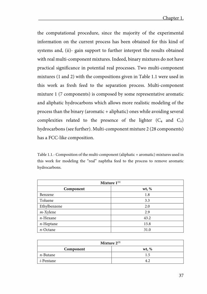
Chapter 1.
37
the computational procedure, since the majority of the experimental
information on the current process has been obtained for this kind of
systems and, (ii)- gain support to further interpret the results obtained
with real multi-component mixtures. Indeed, binary mixtures do not have
practical significance in potential real processes. Two multi-component
mixtures (1 and 2) with the compositions given in Table 1.1 were used in
this work as fresh feed to the separation process. Multi-component
mixture 1 (7 components) is composed by some representative aromatic
and aliphatic hydrocarbons which allows more realistic modeling of the
process than the binary (aromatic + aliphatic) ones while avoiding several
complexities related to the presence of the lighter (C₄ and C₅)
hydrocarbons (see further). Multi-component mixture 2 (28 components)
has a FCC-like composition.
Table 1.1.- Composition of the multi-component (aliphatic + aromatic) mixtures used in this work for modeling the “real” naphtha feed to the process to remove aromatic hydrocarbons.
Mixture 1(1) Component wt, %
Benzene 1.8 Toluene 3.3 Ethylbenzene 2.0 m-Xylene 2.9 n-Hexane 43.2 n-Heptane 15.8 n-Octane 31.0
Mixture 2(2) Component wt, %
n-Butane 1.5 i-Pentane 4.2
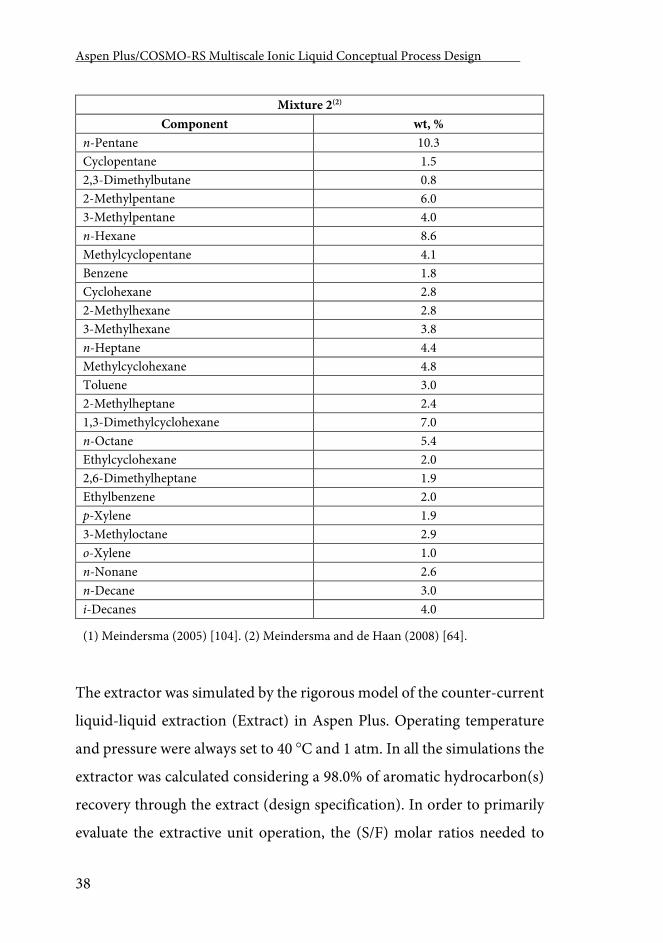
Aspen Plus/COSMO-RS Multiscale Ionic Liquid Conceptual Process Design .
38
Mixture 2(2) Component wt, %
n-Pentane 10.3 Cyclopentane 1.5 2,3-Dimethylbutane 0.8 2-Methylpentane 6.0 3-Methylpentane 4.0 n-Hexane 8.6 Methylcyclopentane 4.1 Benzene 1.8 Cyclohexane 2.8 2-Methylhexane 2.8 3-Methylhexane 3.8 n-Heptane 4.4 Methylcyclohexane 4.8 Toluene 3.0 2-Methylheptane 2.4 1,3-Dimethylcyclohexane 7.0 n-Octane 5.4 Ethylcyclohexane 2.0 2,6-Dimethylheptane 1.9 Ethylbenzene 2.0 p-Xylene 1.9 3-Methyloctane 2.9 o-Xylene 1.0 n-Nonane 2.6 n-Decane 3.0 i-Decanes 4.0
(1) Meindersma (2005) [104]. (2) Meindersma and de Haan (2008) [64].
The extractor was simulated by the rigorous model of the counter-current
liquid-liquid extraction (Extract) in Aspen Plus. Operating temperature
and pressure were always set to 40 C and 1 atm. In all the simulations the
extractor was calculated considering a 98.0% of aromatic hydrocarbon(s)
recovery through the extract (design specification). In order to primarily
evaluate the extractive unit operation, the (S/F) molar ratios needed to
Chapter 1.
39
reach the target recovery were computed for different numbers of
equilibrium stages (N). Based on these data, the (S/F) molar ratio for N →
∞ ((S/F)min.) was determined for the systems assessed. Afterwards, the
operation performance was detailed evaluated for the most promising
studied ILs in a 12 equilibrium stages column. This allows the direct
comparison of the present results with those published elsewhere [1, 27].
Performances of the extractive unit operation with different ILs were
evaluated in terms of solvent consumption, (S/F), and product recoveries
and/or purities (aromatics in the extract and aliphatics in the raffinate).
Recoveries or purities were used casuistically depending on the
relationship studied.
Analysis of the extractive process operation was conducted sequentially
throughout the following systems: (i)- binary model (aliphatic + aromatic)
mixtures using individual ILs as extracting solvents, (ii)- multi-
component (aliphatic + aromatic) mixtures (1 and 2) with individual ILs
and finally, (iii)- multi-component (aliphatic + aromatic) mixtures (1 and
2) with binary to quaternary (IL – IL) mixtures as extracting agents.
The two-outlet VL flash model in Aspen Plus (FLASH2) was used for
modeling the IL regenerator. The operating temperature at the
regenerator was selected in order to avoid the thermal decomposition of
the regenerated IL(s). [3-mebupy][DCN] and [4-mebupy][BF4] begin to
decompose at c.a. 230-250 C whereas [NTf2] and [TfO] ILs decompose at
320-330 C [21-24]. In all the process simulations of the IL regenerator,
the following design specifications were set: (i)- the IL recovered was 99.0
mol% pure, (ii)- the mixture to be separated was fed at the bubble point
Aspen Plus/COSMO-RS Multiscale Ionic Liquid Conceptual Process Design .
40
temperature for the corresponding operating pressure and, (iii)- operating
temperature was fixed to 230 C for [3-mebupy][DCN] and [4-
mebupy][BF4] ILs or 320 C for [TfO]- and [NTf2]- ILs. The next two
process variables were used to evaluate the IL regeneration process
operation: (i)- the operating (equilibrium) pressure at which the target
separation was reached for the specified temperature and, (ii)- the
calculated heat duty (in kJ per kg of IL regenerated) of the operation. This
treatment is similar to the one employed in our previous study [153].
Four different situations were studied in relation to the IL regeneration:
(i)- individual ILs were regenerated from their binary mixtures with
different aromatic hydrocarbons. This is a hypothetical circumstance
because it essentially assumes a perfect separation in the extractor.
However, it can give a general outlook about the influence of the IL and
aromatic nature on the operating conditions and energetic requirements
of the IL regeneration. 15 wt% aromatic mixtures were supposed every
time, (ii)- individual ILs were regenerated from their ternary mixtures
with (aromatic + aliphatic) hydrocarbons.
The presence of aliphatic hydrocarbons in the extract is not desirable not
only because it reduces their recovery through the raffinate and the
aromatic purity in the proper extract but also because it represents an extra
energetic load in the IL regeneration (see below). However, it is
unavoidable when multi-component “real” (aromatic + aliphatic)
mixtures are fed to the process because the previous extraction does not
completely separate aromatic and aliphatic hydrocarbons. Hence, the
consequence of the aliphatic hydrocarbon presence in the mixture feed to
Chapter 1.
41
the IL regeneration on both the operating conditions and the energetic
needs of the IL recovery were analyzed previously to discuss the IL
regeneration from multi-component (aromatic + aliphatic) mixtures. In
these studies, 2 wt% of n-hexane, n-heptane or n-octane was always added
to mixtures of different ILs and aromatic hydrocarbons (benzene, toluene,
ethylbenzene and m-xylene). Aliphatic addition was made in such a way
that the flows of the remaining components of the mixture (aromatic and
IL) were kept constant; (iii)- individual ILs were regenerated from the
extract resulting from the extraction of multi-component real mixtures 1
and 2 and, (iv)- (IL – IL) mixtures were regenerated from the real extracts
(as in the previous situation).
3.- Results and discussion
3.1.- Property prediction of pure ILs and their mixtures with the organic
compounds
Densities, viscosities, heat capacities and heats of vaporization predicted
by Aspen Plus and Aspen HYSYS simulations (with the COSMOSAC
property model) for the pure ILs used in this work agree reasonably well
(Figure 1.2) with experimental reported data. Computed RAADs (in %)
for all the ILs included in this work are 2.4, 5.0, 8.7 and 9.8, respectively,
for the mentioned properties. These accuracies are similar to those
obtained by us in other related works where a similar computational
procedure was used [56, 153, 162].
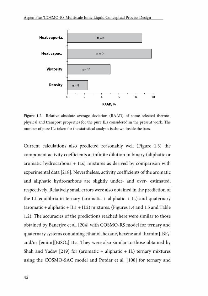
Aspen Plus/COSMO-RS Multiscale Ionic Liquid Conceptual Process Design .
42
Figure 1.2.- Relative absolute average deviation (RAAD) of some selected thermo-physical and transport properties for the pure ILs considered in the present work. The number of pure ILs taken for the statistical analysis is shown inside the bars.
Current calculations also predicted reasonably well (Figure 1.3) the
component activity coefficients at infinite dilution in binary (aliphatic or
aromatic hydrocarbons + ILs) mixtures as derived by comparison with
experimental data [218]. Nevertheless, activity coefficients of the aromatic
and aliphatic hydrocarbons are slightly under- and over- estimated,
respectively. Relatively small errors were also obtained in the prediction of
the LL equilibria in ternary (aromatic + aliphatic + IL) and quaternary
(aromatic + aliphatic + IL1 + IL2) mixtures. (Figures 1.4 and 1.5 and Table
1.2). The accuracies of the predictions reached here were similar to those
obtained by Banerjee et al. [204] with COSMO-RS model for ternary and
quaternary systems containing ethanol, hexane, hexene and [hxmim][BF4]
and/or [emim][EtSO4] ILs. They were also similar to those obtained by
Shah and Yadav [219] for (aromatic + aliphatic + IL) ternary mixtures
using the COSMO-SAC model and Potdar et al. [100] for ternary and
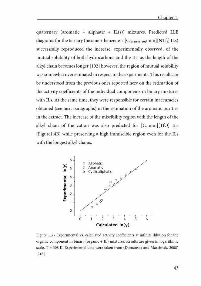
Chapter 1.
43
quaternary (aromatic + aliphatic + IL(s)) mixtures. Predicted LLE
diagrams for the ternary (hexane + benzene + [C₍₂,₄,₆,₈,₁₀₎mim][NTf2] ILs)
successfully reproduced the increase, experimentally observed, of the
mutual solubility of both hydrocarbons and the ILs as the length of the
alkyl chain becomes longer [102] however, the region of mutual solubility
was somewhat overestimated in respect to the experiments. This result can
be understood from the previous ones reported here on the estimation of
the activity coefficients of the individual components in binary mixtures
with ILs. At the same time, they were responsible for certain inaccuracies
obtained (see next paragraphs) in the estimation of the aromatic purities
in the extract. The increase of the miscibility region with the length of the
alkyl chain of the cation was also predicted for [Cnmim][TfO] ILs
(Figure1.4B) while preserving a high immiscible region even for the ILs
with the longest alkyl chains.
Figure 1.3.- Experimental vs. calculated activity coefficients at infinite dilution for the organic component in binary (organic + IL) mixtures. Results are given in logarithmic scale. T = 308 K. Experimental data were taken from (Domanska and Marciniak, 2008) [218]
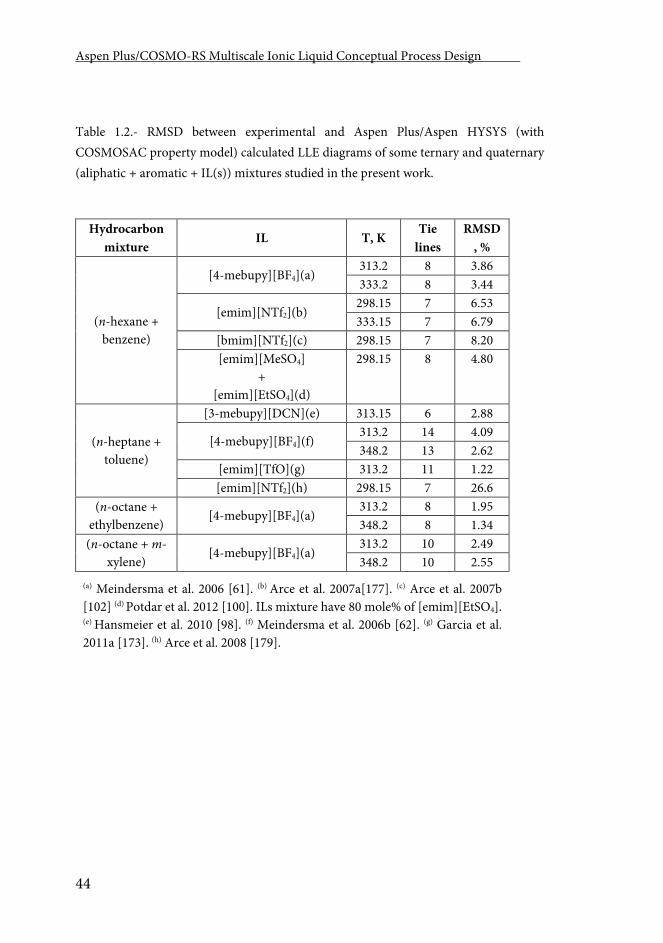
Aspen Plus/COSMO-RS Multiscale Ionic Liquid Conceptual Process Design .
44
Table 1.2.- RMSD between experimental and Aspen Plus/Aspen HYSYS (with COSMOSAC property model) calculated LLE diagrams of some ternary and quaternary (aliphatic + aromatic + IL(s)) mixtures studied in the present work.
Hydrocarbon mixture
IL T, K Tie
lines RMSD
, %
(n-hexane + benzene)
[4-mebupy][BF4](a) 313.2 8 3.86 333.2 8 3.44
[emim][NTf2](b) 298.15 7 6.53 333.15 7 6.79
[bmim][NTf2](c) 298.15 7 8.20 [emim][MeSO4]
+ [emim][EtSO4](d)
298.15 8 4.80
(n-heptane + toluene)
[3-mebupy][DCN](e) 313.15 6 2.88
[4-mebupy][BF4](f) 313.2 14 4.09 348.2 13 2.62
[emim][TfO](g) 313.2 11 1.22 [emim][NTf2](h) 298.15 7 26.6
(n-octane + ethylbenzene)
[4-mebupy][BF4](a) 313.2 8 1.95 348.2 8 1.34
(n-octane + m-xylene)
[4-mebupy][BF4](a) 313.2 10 2.49 348.2 10 2.55
(a) Meindersma et al. 2006 [61]. (b) Arce et al. 2007a[177]. (c) Arce et al. 2007b [102] (d) Potdar et al. 2012 [100]. ILs mixture have 80 mole% of [emim][EtSO4]. (e) Hansmeier et al. 2010 [98]. (f) Meindersma et al. 2006b [62]. (g) Garcia et al. 2011a [173]. (h) Arce et al. 2008 [179].
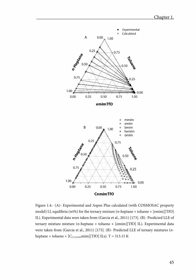
Chapter 1.
45
Figure 1.4.- (A)- Experimental and Aspen Plus calculated (with COSMOSAC property model) LL equilibria (wt%) for the ternary mixture (n-heptane + toluene + [emim][TfO] IL). Experimental data were taken from (Garcia et al., 2011) [173]. (B)- Predicted LLE of ternary mixture mixture (n-heptane + toluene + [emim][TfO] IL). Experimental data were taken from (Garcia et al., 2011) [173]. (B)- Predicted LLE of ternary mixtures (n-heptane + toluene + [C(1,2,4,6,8)mim][TfO] ILs). T = 313.15 K
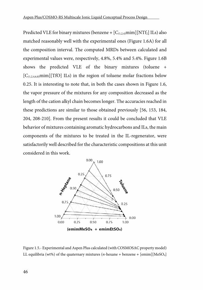
Aspen Plus/COSMO-RS Multiscale Ionic Liquid Conceptual Process Design .
46
Predicted VLE for binary mixtures (benzene + [C(1,2,4)mim][NTf2] ILs) also
matched reasonably well with the experimental ones (Figure 1.6A) for all
the composition interval. The computed MRDs between calculated and
experimental values were, respectively, 4.8%, 5.4% and 5.4%. Figure 1.6B
shows the predicted VLE of the binary mixtures (toluene +
[C(1,2,4,6,8)mim][TfO] ILs) in the region of toluene molar fractions below
0.25. It is interesting to note that, in both the cases shown in Figure 1.6,
the vapor pressure of the mixtures for any composition decreased as the
length of the cation alkyl chain becomes longer. The accuracies reached in
these predictions are similar to those obtained previously [56, 153, 184,
204, 208-210]. From the present results it could be concluded that VLE
behavior of mixtures containing aromatic hydrocarbons and ILs, the main
components of the mixtures to be treated in the IL-regenerator, were
satisfactorily well described for the characteristic compositions at this unit
considered in this work.
Figure 1.5.- Experimental and Aspen Plus calculated (with COSMOSAC property model) LL equilibria (wt%) of the quaternary mixtures (n-hexane + benzene + [emim][MeSO4]
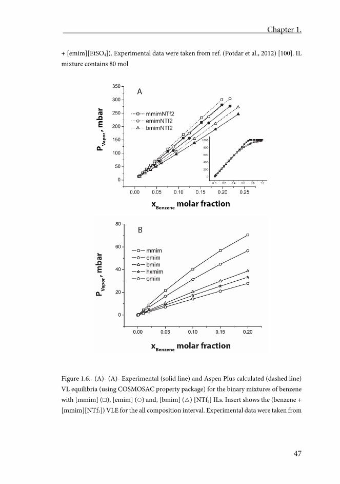
Chapter 1.
47
+ [emim][EtSO4]). Experimental data were taken from ref. (Potdar et al., 2012) [100]. IL mixture contains 80 mol
Figure 1.6.- (A)- (A)- Experimental (solid line) and Aspen Plus calculated (dashed line) VL equilibria (using COSMOSAC property package) for the binary mixtures of benzene with [mmim] (), [emim] () and, [bmim] () [NTf2] ILs. Insert shows the (benzene + [mmim][NTf2]) VLE for the all composition interval. Experimental data were taken from
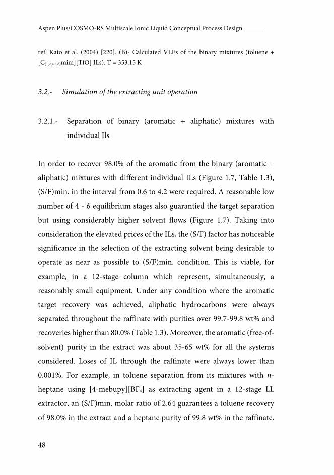
Aspen Plus/COSMO-RS Multiscale Ionic Liquid Conceptual Process Design .
48
ref. Kato et al. (2004) [220]. (B)- Calculated VLEs of the binary mixtures (toluene + [C(1,2,4,6,8)mim][TfO] ILs). T = 353.15 K
3.2.- Simulation of the extracting unit operation
3.2.1.- Separation of binary (aromatic + aliphatic) mixtures with
individual Ils
In order to recover 98.0% of the aromatic from the binary (aromatic +
aliphatic) mixtures with different individual ILs (Figure 1.7, Table 1.3),
(S/F)min. in the interval from 0.6 to 4.2 were required. A reasonable low
number of 4 - 6 equilibrium stages also guarantied the target separation
but using considerably higher solvent flows (Figure 1.7). Taking into
consideration the elevated prices of the ILs, the (S/F) factor has noticeable
significance in the selection of the extracting solvent being desirable to
operate as near as possible to (S/F)min. condition. This is viable, for
example, in a 12-stage column which represent, simultaneously, a
reasonably small equipment. Under any condition where the aromatic
target recovery was achieved, aliphatic hydrocarbons were always
separated throughout the raffinate with purities over 99.7-99.8 wt% and
recoveries higher than 80.0% (Table 1.3). Moreover, the aromatic (free-of-
solvent) purity in the extract was about 35-65 wt% for all the systems
considered. Loses of IL through the raffinate were always lower than
0.001%. For example, in toluene separation from its mixtures with n-
heptane using [4-mebupy][BF4] as extracting agent in a 12-stage LL
extractor, an (S/F)min. molar ratio of 2.64 guarantees a toluene recovery
of 98.0% in the extract and a heptane purity of 99.8 wt% in the raffinate.
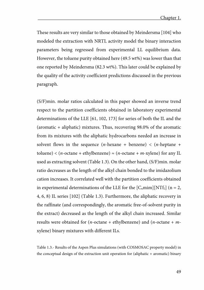
Chapter 1.
49
These results are very similar to those obtained by Meindersma [104] who
modeled the extraction with NRTL activity model the binary interaction
parameters being regressed from experimental LL equilibrium data.
However, the toluene purity obtained here (49.5 wt%) was lower than that
one reported by Meindersma (82.3 wt%). This later could be explained by
the quality of the activity coefficient predictions discussed in the previous
paragraph.
(S/F)min. molar ratios calculated in this paper showed an inverse trend
respect to the partition coefficients obtained in laboratory experimental
determinations of the LLE [61, 102, 173] for series of both the IL and the
(aromatic + aliphatic) mixtures. Thus, recovering 98.0% of the aromatic
from its mixtures with the aliphatic hydrocarbons needed an increase in
solvent flows in the sequence (n-hexane + benzene) < (n-heptane +
toluene) < (n-octane + ethylbenzene) ≈ (n-octane + m-xylene) for any IL
used as extracting solvent (Table 1.3). On the other hand, (S/F)min. molar
ratio decreases as the length of the alkyl chain bonded to the imidazolium
cation increases. It correlated well with the partition coefficients obtained
in experimental determinations of the LLE for the [Cnmim][NTf2] (n = 2,
4, 6, 8) IL series [102] (Table 1.3). Furthermore, the aliphatic recovery in
the raffinate (and correspondingly, the aromatic free-of-solvent purity in
the extract) decreased as the length of the alkyl chain increased. Similar
results were obtained for (n-octane + ethylbenzene) and (n-octane + m-
xylene) binary mixtures with different ILs.
Table 1.3.- Results of the Aspen Plus simulations (with COSMOSAC property model) in the conceptual design of the extraction unit operation for (aliphatic + aromatic) binary
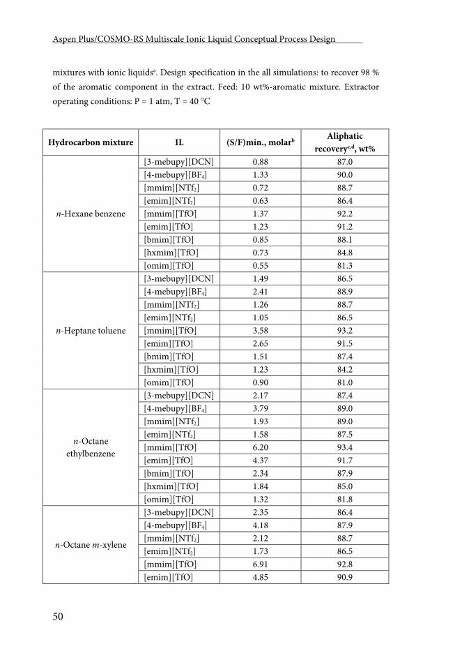
Aspen Plus/COSMO-RS Multiscale Ionic Liquid Conceptual Process Design .
50
mixtures with ionic liquidsa. Design specification in the all simulations: to recover 98 % of the aromatic component in the extract. Feed: 10 wt%-aromatic mixture. Extractor operating conditions: P = 1 atm, T = 40 C
Hydrocarbon mixture IL (S/F)min., molarb Aliphatic
recoveryc,d, wt%
n-Hexane benzene
[3-mebupy][DCN] 0.88 87.0 [4-mebupy][BF4] 1.33 90.0 [mmim][NTf2] 0.72 88.7 [emim][NTf2] 0.63 86.4 [mmim][TfO] 1.37 92.2 [emim][TfO] 1.23 91.2 [bmim][TfO] 0.85 88.1 [hxmim][TfO] 0.73 84.8 [omim][TfO] 0.55 81.3
n-Heptane toluene
[3-mebupy][DCN] 1.49 86.5 [4-mebupy][BF4] 2.41 88.9 [mmim][NTf2] 1.26 88.7 [emim][NTf2] 1.05 86.5 [mmim][TfO] 3.58 93.2 [emim][TfO] 2.65 91.5 [bmim][TfO] 1.51 87.4 [hxmim][TfO] 1.23 84.2 [omim][TfO] 0.90 81.0
n-Octane ethylbenzene
[3-mebupy][DCN] 2.17 87.4 [4-mebupy][BF4] 3.79 89.0 [mmim][NTf2] 1.93 89.0 [emim][NTf2] 1.58 87.5 [mmim][TfO] 6.20 93.4 [emim][TfO] 4.37 91.7 [bmim][TfO] 2.34 87.9 [hxmim][TfO] 1.84 85.0 [omim][TfO] 1.32 81.8
n-Octane m-xylene
[3-mebupy][DCN] 2.35 86.4 [4-mebupy][BF4] 4.18 87.9 [mmim][NTf2] 2.12 88.7 [emim][NTf2] 1.73 86.5 [mmim][TfO] 6.91 92.8 [emim][TfO] 4.85 90.9
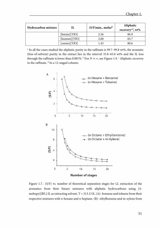
Chapter 1.
51
Hydrocarbon mixture IL (S/F)min., molarb Aliphatic
recoveryc,d, wt% [bmim][TfO] 2.56 86.9 [hxmim][TfO] 2.00 83.7 [omim][TfO] 1.43 80.6
a In all the cases studied the aliphatic purity in the raffinate is 99.7–99.8 wt%, the aromatic (free-of-solvent) purity in the extract lies in the interval 35.0–65.0 wt% and the IL loss through the raffinate is lower than 0.001%. b For N → ∞, see Figure 1.9. c Aliphatic recovery in the raffinate. d In a 12-staged column.
Figure 1.7.- (S/F) vs. number of theoretical separation stages for LL extraction of the aromatics from their binary mixtures with aliphatic hydrocarbons using [4-mebupy][BF4] IL as extracting solvent. T = 313.15 K. (A)- benzene and toluene from their respective mixtures with n-hexane and n-heptane. (B)- ethylbenzene and m-xylene from
Aspen Plus/COSMO-RS Multiscale Ionic Liquid Conceptual Process Design .
52
their mixtures with n-octane. Profiles shown here are analogous to those obtained for all the other ILs studied in this work with the same binary (aromatic + aliphatic) mixtures
3.2.2.- Separation of multi-component (aromatic + aliphatic) mixtures
with individual ILs
Results (Table 1.4) of the aromatic and aliphatic separation with some
individual ILs when multi-component mixtures 1 and 2 were fed to a 12-
stage extraction column (fixing overall 98.0% recovery for the aromatics)
were consistent with the results obtained for the corresponding binary
mixtures (Table 1.3) as reflected in the following evidences: (i)- the
(S/F)min. ratio decreased in the sequence: [mmim][TfO] > [4-
mebupy][BF4] > [mmim][NTf2] ≈ [3-mebupy][DCN] (Table 1.4) similarly
to the individual binary mixtures (Table 1.3), (ii)- for a specific extracting
solvent, [4-mebupy][BF4] for instance, aliphatic hydrocarbons in the
raffinate yielded 98.8 wt% purity and 85.8% recovery, whereas the overall
aromatic free-of-solvent purity was 72.9% when aromatics were separated
from multi-component mixture 1 (Table 1.4). This result was also similar
to the results obtained for binary mixtures (n-heptane + toluene), for
example, using the same IL flow (Table 1.3), (iii)- individual aromatic
recoveries (in the extract) from multi-component mixture 1, using a (S/F)
molar ratio 3.5 in a 12-stage column follow the sequence: benzene (100%)
> toluene (99.9%) > ethylbenzene (97.7%) > m-xylene (93.2%), which is
comparable to that one obtained for binary mixtures containing the same
aromatics. When multi-component mixture 2 was fed to the extraction
column, calculated (S/F)min. molar ratios and aliphatic recoveries were
very similar to those obtained for multi-component mixture 1. However,
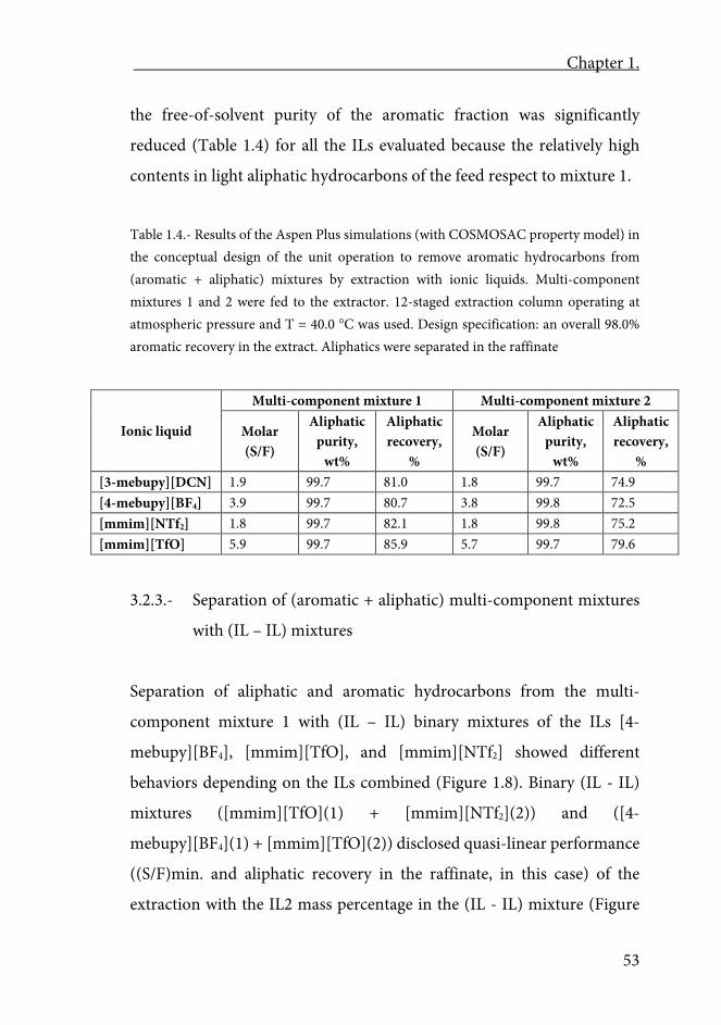
Chapter 1.
53
the free-of-solvent purity of the aromatic fraction was significantly
reduced (Table 1.4) for all the ILs evaluated because the relatively high
contents in light aliphatic hydrocarbons of the feed respect to mixture 1.
Table 1.4.- Results of the Aspen Plus simulations (with COSMOSAC property model) in the conceptual design of the unit operation to remove aromatic hydrocarbons from (aromatic + aliphatic) mixtures by extraction with ionic liquids. Multi-component mixtures 1 and 2 were fed to the extractor. 12-staged extraction column operating at atmospheric pressure and T = 40.0 C was used. Design specification: an overall 98.0% aromatic recovery in the extract. Aliphatics were separated in the raffinate
Ionic liquid
Multi-component mixture 1 Multi-component mixture 2
Molar (S/F)
Aliphatic purity,
wt%
Aliphatic recovery,
%
Molar (S/F)
Aliphatic purity,
wt%
Aliphatic recovery,
% [3-mebupy][DCN] 1.9 99.7 81.0 1.8 99.7 74.9 [4-mebupy][BF4] 3.9 99.7 80.7 3.8 99.8 72.5 [mmim][NTf2] 1.8 99.7 82.1 1.8 99.8 75.2 [mmim][TfO] 5.9 99.7 85.9 5.7 99.7 79.6
3.2.3.- Separation of (aromatic + aliphatic) multi-component mixtures
with (IL – IL) mixtures
Separation of aliphatic and aromatic hydrocarbons from the multi-
component mixture 1 with (IL – IL) binary mixtures of the ILs [4-
mebupy][BF4], [mmim][TfO], and [mmim][NTf2] showed different
behaviors depending on the ILs combined (Figure 1.8). Binary (IL - IL)
mixtures ([mmim][TfO](1) + [mmim][NTf2](2)) and ([4-
mebupy][BF4](1) + [mmim][TfO](2)) disclosed quasi-linear performance
((S/F)min. and aliphatic recovery in the raffinate, in this case) of the
extraction with the IL2 mass percentage in the (IL - IL) mixture (Figure
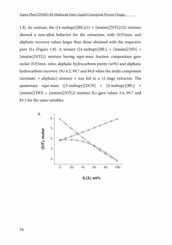
Aspen Plus/COSMO-RS Multiscale Ionic Liquid Conceptual Process Design .
54
1.8). In contrast, the ([4-mebupy][BF4](1) + [mmim][NTf2](2)) mixture
showed a non-ideal behavior for the extraction, with (S/F)min. and
aliphatic recovery values larger than those obtained with the respective
pure ILs (Figure 1.8). A ternary ([4-mebupy][BF4] + [mmim][TfO] +
[mmim][NTf2]) mixture having equi-mass fraction composition gave
molar (S/F)min. ratio, aliphatic hydrocarbons purity (wt%) and aliphatic
hydrocarbons recovery (%) 4.2, 99.7 and 84.0 when the multi-component
(aromatic + aliphatic) mixture 1 was fed to a 12-stage extractor. The
quaternary equi-mass ([3-mebupy][DCN] + [4-mebupy][BF4] +
[mmim][TfO] + [mmim][NTf2]) mixture ILs gave values 3.4, 99.7 and
83.3 for the same variables.
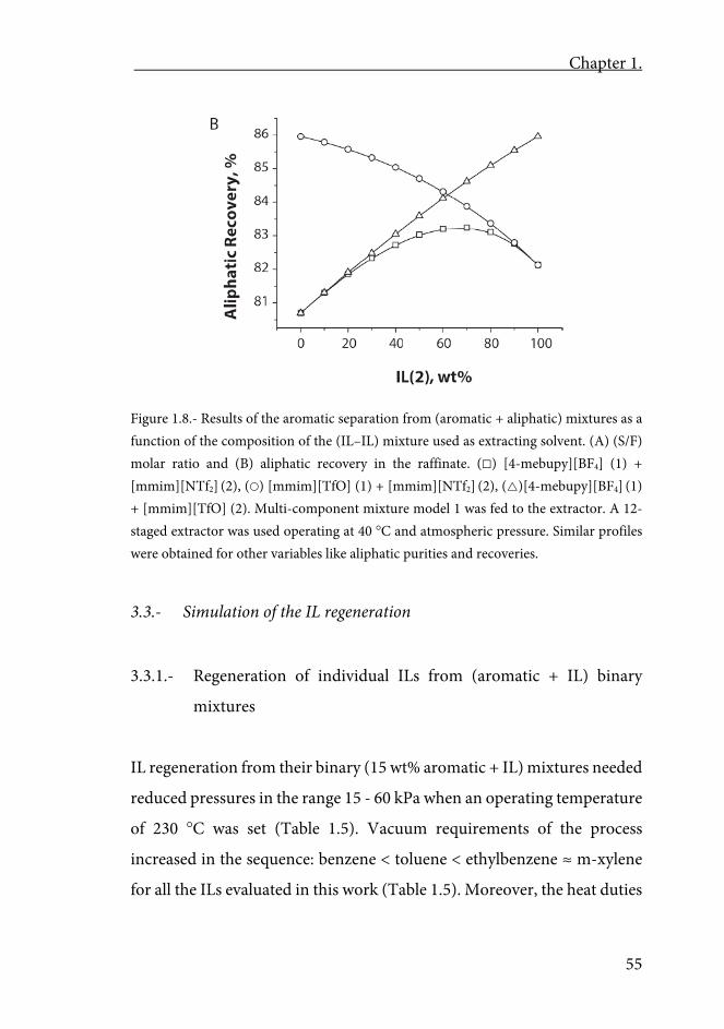
Chapter 1.
55
Figure 1.8.- Results of the aromatic separation from (aromatic + aliphatic) mixtures as a function of the composition of the (IL–IL) mixture used as extracting solvent. (A) (S/F) molar ratio and (B) aliphatic recovery in the raffinate. () [4-mebupy][BF4] (1) + [mmim][NTf2] (2), () [mmim][TfO] (1) + [mmim][NTf2] (2), ()[4-mebupy][BF4] (1) + [mmim][TfO] (2). Multi-component mixture model 1 was fed to the extractor. A 12-staged extractor was used operating at 40 C and atmospheric pressure. Similar profiles were obtained for other variables like aliphatic purities and recoveries.
3.3.- Simulation of the IL regeneration
3.3.1.- Regeneration of individual ILs from (aromatic + IL) binary
mixtures
IL regeneration from their binary (15 wt% aromatic + IL) mixtures needed
reduced pressures in the range 15 - 60 kPa when an operating temperature
of 230 C was set (Table 1.5). Vacuum requirements of the process
increased in the sequence: benzene < toluene < ethylbenzene ≈ m-xylene
for all the ILs evaluated in this work (Table 1.5). Moreover, the heat duties
Aspen Plus/COSMO-RS Multiscale Ionic Liquid Conceptual Process Design .
56
(QIL-Regener.) required to regenerate the ILs from their mixtures with
aromatics under the same conditions are in the range 300 – 450 kJ/kg-IL-
regenerated (Table 1.5), following the opposite tendency in respect to the
operating pressures for the aromatic hydrocarbons. Similar results were
obtained when heat duties were given in kJ/kg-aromatic-removed. For
NTf2 and TfO ILs, setting the operating temperature at the IL regenerator
to 320 C (see Computational details), allowed the process to operate at
higher pressures even near to the atmospheric one when TfO ILs were
used as extracting solvents (Figure 1.9A). Increases of the equilibrium
pressure computed for (15 wt% aromatic + [mmim][NTf2]) mixtures
under temperature growths from 230 to 320 C were 51.9, 40.4, 31.8 and
33.1 with benzene, toluene, ethylbenzene and m-xylene, respectively.
Nevertheless, the increase of the operating temperature simultaneously
had a negative energetic effect since the heating requirements of the
aromatic removal from their binary mixtures with ILs increased (Figure
1.9B) approximately 1.4 times (115 - 125 kJ/kg-IL-regenerated) for all the
studied (15 wt% aromatics + [mmim][TfO] or [mmim][NTf2]) mixtures
in the temperature interval 230 - 320 C.
Table 1.5. Results of the Aspen Plus simulations (with COSMOSAC
property model) in the conceptual design of the individual IL regeneration
by vacuum distillation from their binary (15 wt% aromatic + IL) mixtures
with some selected aromatics. Mixtures are feed to the regenerator at the
corresponding bubble point temperature. Regenerator operating
temperature was 230.0 C. Purity of the IL regenerated was 99.0 mole%
Chapter 1.
57
Table 1.5.- Results of the Aspen Plus simulations (with COSMOSAC property model) in the conceptual design of the individual IL regeneration by vacuum distillation from their binary (15 wt% aromatic + IL) mixtures with some selected aromatics. Mixtures are feed to the regenerator at the corresponding bubble point temperature. Regenerator operating temperature was 230.0 C. Purity of the IL regenerated was 99.0 mole%
Aromatic Equilibrium pressure, kPa
[3-mebupy][DCN] [4-mebupy][BF4] [mmim][NTf2] [mmim][TfO] Benzene 33.3 51.7 28.1 55.1 Toluene 23.8 40.6 20.1 44.5 Ethylbenzene 17.6 32.5 14.9 36.5 m-Xylene 17.6 32.9 14.9 36.7
Aromatic QIL-Regener., kJ/kg-IL-regenerated
[3-mebupy][DCN] [4-mebupy][BF4] [mmim][NTf2] [mmim][TfO] Benzene 459 453 325 362 Toluene 424 418 303 334 Ethylbenzene 395 389 285 311 m-Xylene 391 385 282 308
Regeneration of individual ILs from ternary (aliphatic + aromatic + IL)
mixtures
An extra (2 wt%) aliphatic (n-hexane, n-heptane or n-octane) load in the
(aromatic + IL) mixtures increased the operating pressure making the IL
regeneration possible under weaker vacuum conditions. However,
simultaneously the heat requirements of the regeneration increased
(Figure 1.10). Average increments (at 230 C) were approx. 25% for the
equilibrium pressure and approx. 20% for the heat duties for the
[mmim][TfO] regeneration, respect to the values shown in Table 1.5.
These increases were moderated regenerating [mmim][NTf2] (average
growths: 10.6% and 13.1% for pressure and QIL-Regener.) and [4-
mebupy][BF4] (average growths: 10.5% and 14.3% for pressure and QIL-
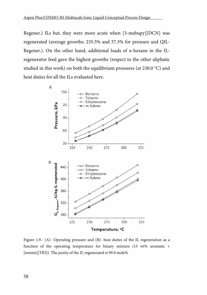
Aspen Plus/COSMO-RS Multiscale Ionic Liquid Conceptual Process Design .
58
Regener.) ILs but, they were more acute when [3-mebupy][DCN] was
regenerated (average growths: 235.5% and 57.3% for pressure and QIL-
Regener.). On the other hand, additional loads of n-hexane in the IL-
regenerator feed gave the highest growths (respect to the other aliphatic
studied in this work) on both the equilibrium pressures (at 230.0 C) and
heat duties for all the ILs evaluated here.
Figure 1.9.- (A)- Operating pressure and (B)- heat duties of the IL regeneration as a function of the operating temperature for binary mixture (15 wt% aromatic + [mmim][TfO]). The purity of the IL regenerated is 99.0 mole%
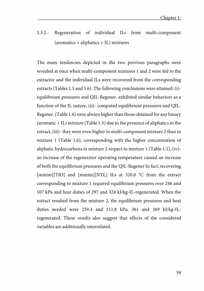
Chapter 1.
59
3.3.2.- Regeneration of individual ILs from multi-component
(aromatics + aliphatics + IL) mixtures
The main tendencies depicted in the two previous paragraphs were
revealed at once when multi-component mixtures 1 and 2 were fed to the
extractor and the individual ILs were recovered from the corresponding
extracts (Tables 1.5 and 1.6). The following conclusions were attained: (i)-
equilibrium pressures and QIL-Regener. exhibited similar behaviors as a
function of the IL nature, (ii)- computed equilibrium pressures and QIL-
Regener. (Table 1.6) were always higher than those obtained for any binary
(aromatic + IL) mixture (Table 1.5) due to the presence of aliphatics in the
extract, (iii)- they were even higher in multi-component mixture 2 than in
mixture 1 (Table 1.6), corresponding with the higher concentration of
aliphatic hydrocarbons in mixture 2 respect to mixture 1 (Table 1.1), (iv)-
an increase of the regenerator operating temperature caused an increase
of both the equilibrium pressures and the QIL-Regener In fact, recovering
[mmim][TfO] and [mmim][NTf2] ILs at 320.0 C from the extract
corresponding to mixture 1 required equilibrium pressures over 246 and
107 kPa and heat duties of 297 and 324 kJ/kg-IL-regenerated. When the
extract resulted from the mixture 2, the equilibrium pressures and heat
duties needed were 259.4 and 111.8 kPa; 361 and 369 kJ/kg-IL-
regenerated. These results also suggest that effects of the considered
variables are additionally interrelated.
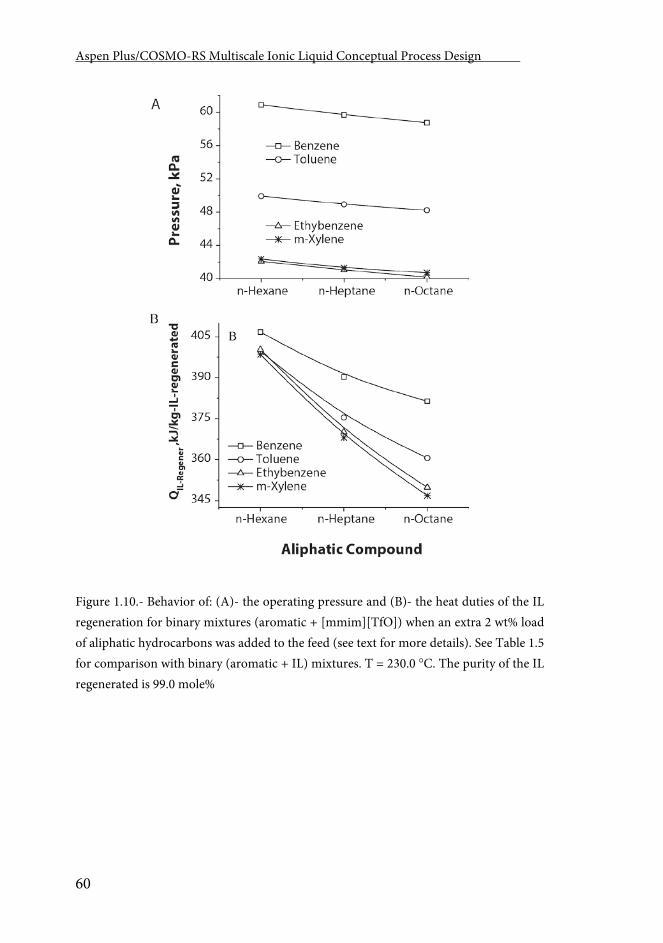
Aspen Plus/COSMO-RS Multiscale Ionic Liquid Conceptual Process Design .
60
Figure 1.10.- Behavior of: (A)- the operating pressure and (B)- the heat duties of the IL regeneration for binary mixtures (aromatic + [mmim][TfO]) when an extra 2 wt% load of aliphatic hydrocarbons was added to the feed (see text for more details). See Table 1.5 for comparison with binary (aromatic + IL) mixtures. T = 230.0 C. The purity of the IL regenerated is 99.0 mole%
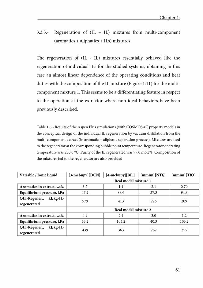
Chapter 1.
61
3.3.3.- Regeneration of (IL – IL) mixtures from multi-component
(aromatics + aliphatics + ILs) mixtures
The regeneration of (IL - IL) mixtures essentially behaved like the
regeneration of individual ILs for the studied systems, obtaining in this
case an almost linear dependence of the operating conditions and heat
duties with the composition of the IL mixture (Figure 1.11) for the multi-
component mixture 1. This seems to be a differentiating feature in respect
to the operation at the extractor where non-ideal behaviors have been
previously described.
Table 1.6.- Results of the Aspen Plus simulations (with COSMOSAC property model) in the conceptual design of the individual IL regeneration by vacuum distillation from the multi-component extract (in aromatic + aliphatic separation process). Mixtures are feed to the regenerator at the corresponding bubble point temperature. Regenerator operating temperature was 230.0 C. Purity of the IL regenerated was 99.0 mole%. Composition of the mixtures fed to the regenerator are also provided
Variable / Ionic liquid [3-mebupy][DCN] [4-mebupy][BF4] [mmim][NTf2] [mmim][TfO] Real model mixture 1 Aromatics in extract, wt% 3.7 1.1 2.1 0.70 Equilibrium pressure, kPa 47.2 88.6 37.3 94.8 QIL-Regener., kJ/kg-IL-regenerated
579 413 226 209
Real model mixture 2 Aromatics in extract, wt% 4.9 2.4 3.0 1.2 Equilibrium pressure, kPa 53.2 104.2 40.3 103.2 QIL-Regener., kJ/kg-IL-regenerated
439 363 262 255
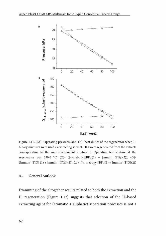
Aspen Plus/COSMO-RS Multiscale Ionic Liquid Conceptual Process Design .
62
Figure 1.11.- (A)- Operating pressures and, (B)- heat duties of the regenerator when IL binary mixtures were used as extracting solvents. ILs were regenerated from the extracts corresponding to the multi-component mixture 1. Operating temperature at the regenerator was 230.0 C. ()- ([4-mebupy][BF4](1) + [mmim][NTf2](2)), ()- ([mmim][TfO] (1) + [mmim][NTf2](2)), ()- ([4-mebupy][BF4](1) + [mmim][TfO](2))
4.- General outlook
Examining of the altogether results related to both the extraction and the
IL regeneration (Figure 1.12) suggests that selection of the IL-based
extracting agent for (aromatic + aliphatic) separation processes is not a
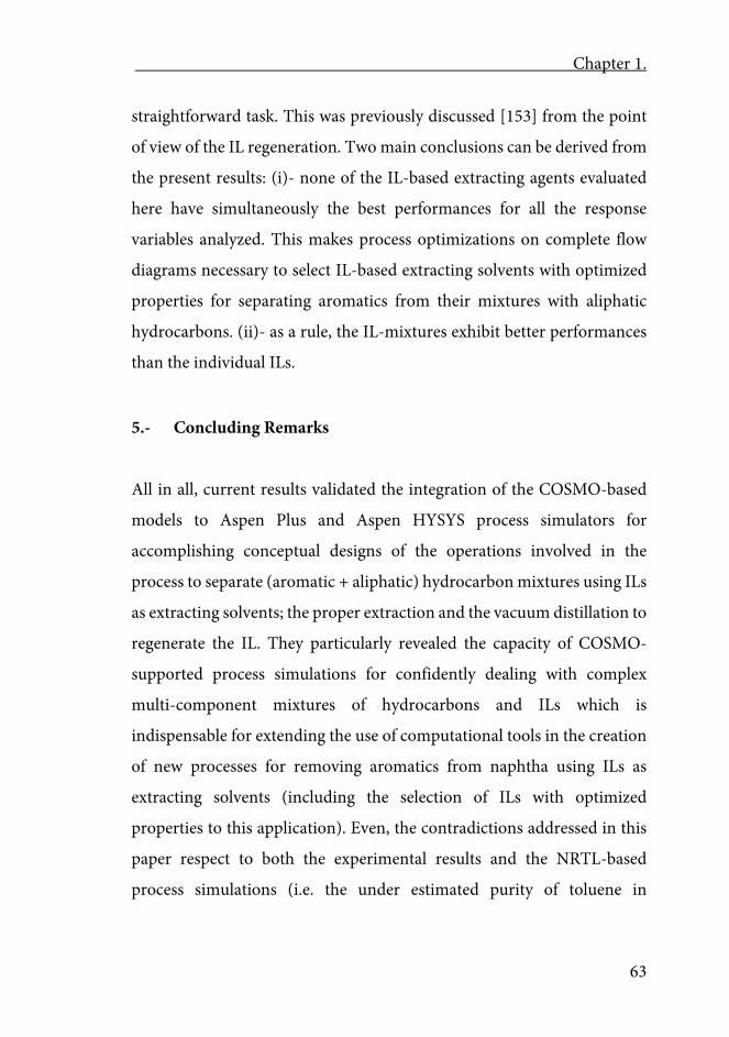
Chapter 1.
63
straightforward task. This was previously discussed [153] from the point
of view of the IL regeneration. Two main conclusions can be derived from
the present results: (i)- none of the IL-based extracting agents evaluated
here have simultaneously the best performances for all the response
variables analyzed. This makes process optimizations on complete flow
diagrams necessary to select IL-based extracting solvents with optimized
properties for separating aromatics from their mixtures with aliphatic
hydrocarbons. (ii)- as a rule, the IL-mixtures exhibit better performances
than the individual ILs.
5.- Concluding Remarks
All in all, current results validated the integration of the COSMO-based
models to Aspen Plus and Aspen HYSYS process simulators for
accomplishing conceptual designs of the operations involved in the
process to separate (aromatic + aliphatic) hydrocarbon mixtures using ILs
as extracting solvents; the proper extraction and the vacuum distillation to
regenerate the IL. They particularly revealed the capacity of COSMO-
supported process simulations for confidently dealing with complex
multi-component mixtures of hydrocarbons and ILs which is
indispensable for extending the use of computational tools in the creation
of new processes for removing aromatics from naphtha using ILs as
extracting solvents (including the selection of ILs with optimized
properties to this application). Even, the contradictions addressed in this
paper respect to both the experimental results and the NRTL-based
process simulations (i.e. the under estimated purity of toluene in
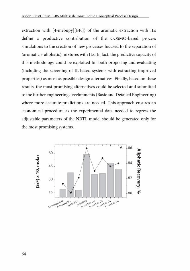
Aspen Plus/COSMO-RS Multiscale Ionic Liquid Conceptual Process Design .
64
extraction with [4-mebupy][BF4]) of the aromatic extraction with ILs
define a productive contribution of the COSMO-based process
simulations to the creation of new processes focused to the separation of
(aromatic + aliphatic) mixtures with ILs. In fact, the predictive capacity of
this methodology could be exploited for both proposing and evaluating
(including the screening of IL-based systems with extracting improved
properties) as most as possible design alternatives. Finally, based on these
results, the most promising alternatives could be selected and submitted
to the further engineering developments (Basic and Detailed Engineering)
where more accurate predictions are needed. This approach ensures an
economical procedure as the experimental data needed to regress the
adjustable parameters of the NRTL model should be generated only for
the most promising systems.
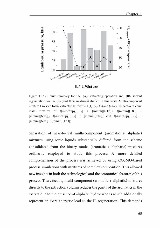
Chapter 1.
65
Figure 1.12.- Result summary for the: (A)- extracting operation and, (B)- solvent regeneration for the ILs (and their mixtures) studied in this work. Multi-component mixture 1 was fed to the extractor. IL mixtures (1), (2), (3) and (4) are, respectively, equi-mass mixtures of ([4-mebupy][BF4] + [mmim][NTf2]), ([mmim][TfO] + [mmim][NTf2]), ([4-mebupy][BF4] + [mmim][TfO]) and ([4-mebupy][BF4] + [mmim][NTf2] + [mmim][TfO])
Separation of near-to-real multi-component (aromatic + aliphatic)
mixtures using ionic liquids substantially differed from the scheme
consolidated from the binary model (aromatic + aliphatic) mixtures
ordinarily employed to study this process. A more detailed
comprehension of the process was achieved by using COSMO-based
process simulations with mixtures of complex composition. This allowed
new insights in both the technological and the economical features of this
process. Thus, feeding multi-component (aromatic + aliphatic) mixtures
directly to the extraction column reduces the purity of the aromatics in the
extract due to the presence of aliphatic hydrocarbons which additionally
represent an extra energetic load to the IL regeneration. This demands
Aspen Plus/COSMO-RS Multiscale Ionic Liquid Conceptual Process Design .
66
new design solutions respect to the simplified flow diagram show in Figure
1.1 of this paper.
IL mixtures seemed to be good extracting solvents for separating aromatic
and aliphatic hydrocarbons. The present results suggest that process
performance could be conveniently tailored by modifying the
composition of the IL-mixture. This is a way to improve the extracting
capacity of the solvent and to reduce the operating costs of the process
owing to the lessening of solvent consumption.
Chapter 2 Aspen Plus Supported Conceptual Design of the Aromatic-
Aliphatic Separation from Low Aromatic Content naphtha
using 4-methyl-N-butylpyridinium tetrafluoroborate Ionic
Liquid
Chapter 2.
69
Chapter 2
Aspen Plus supported conceptual design of the aromatic-aliphatic separation from low aromatic content naphtha using 4-methyl-N-
butylpyridinium tetrafluoroborate Ionic Liquid
Abstract
Three different process to separate aromatic hydrocarbons from a very
low-aromatic-content (10 wt%) naphtha with the 4-methyl-N-
butylpyridinium tetrafluoroborate ionic liquid are analyzed. A computer-
aid methodology recently developed in our group that integrates the
molecular modeling and the process simulation via COSMO-based
thermodynamic models in Aspen Plus is used. The most commonly drawn
process scheme is proposed as Base Case Configuration and two
alternative configurations, one adding water as a co-solvent
(Configuration 1) and the other including a stripper between the
extraction and the solvent regeneration (Configuration 2), are studied.
The processes performance is evaluated through the aliphatic and
aromatic product purities and recoveries, and the solvent and energy
consumptions. The results show that the separation of aromatic
hydrocarbons from this type of naphtha using ionic liquids is possible. The
Base Case Configuration is not able to achieve the separation successfully.
The addition of water as co-solvent guaranties this demand but increases
the solvent and energy consumption. The intermediate stripper seems to
be a promising alternative as it allows achieving high purity aliphatic and
Aspen Plus/COSMO-RS Multiscale Ionic Liquid Conceptual Process Design .
70
aromatic products without increasing the solvent or energy needs. The
results demonstrate that the computational strategy used is capable to
discriminate among complex and relatively similar process alternatives.
1.- Introduction
The benzene, toluene, ethylbenzene and xylene (BTEX) fractions in the
petroleum industry are normally obtained by extraction of reformer (in
the USA) and pyrolysis (in Europe and Japan) gasoline [221]. This process
is carried out, at industrial scale, by the UOP ED sulfolane extraction
process [171]. However, this process has several drawbacks [64]. Due to
the high boiling point of the sulfolane (560K), the regeneration of the
solvent requires high energy consumptions. In addition, the solvent needs
to be recovered not only from the extract but, due to the partial solubility
of the sulfolane in the aliphatic components, also from the raffinate.
Furthermore, the UOP ED sulfolane process is only able to separate
aromatic hydrocarbons from naphtha with a high concentration of
aromatic components [222]. There are other naphtha streams in refineries
that contain large amounts of aromatic components but in lower
concentrations. For instance, the naphtha feed of the ethylene cracker
contains a 10-20% of aromatic compounds. These aromatic hydrocarbons
are not converted into olefins and represent an extra load causing higher
energy consumptions and over dimensioning of the furnaces. Taking this
into account, the effective removal of the aromatic component in a
refinery that feeds 300 tons/h of naphtha to the ethylene crackers could
save 48 M$/year [64]. Additionally, the separated aromatic compounds
Chapter 2.
71
also have their own inherent value as they are used as solvents in the
petrochemical industry or as raw material for the synthesis of many
products such as plastics, colorants or resins. The extraction operation
depends a lot on the solvent selection. Ionic liquids (ILs) are being
evaluated as promising solvents in the separation of aromatics and
aliphatics by liquid-liquid extraction at low temperatures [104]. ILs are
salts that remain liquid under 100 C. There are hundreds of different
cations and anions that could theoretically form thousands of ILs [223] so
are commonly known as designer solvents [3]. Their most remarkable
property is their very low volatility, allowing their regeneration by a fairly
easy vacuum distillation from any other more volatile component [224-
227]. A wide number of pure ILs (<130) have been specifically studied as
solvents for liquid-liquid extraction of benzene, toluene, ethylbenzene or
xylenes from their binary mixtures with different aliphatic hydrocarbons
[62, 63, 102, 106, 178, 179, 227-236]. In most cases, thermodynamic
parameters such as the aromatic (generally toluene) distribution
coefficients or the aromatic/aliphatic selectivity (toluene/heptane in most
cases), calculated from experimental liquid-liquid equilibria (LLE) data,
have been considered for the selection of an adequate IL as extraction
solvent. Higher distribution coefficient requires lower solvent to feed
ratios, while higher selectivity means a purer product and less extraction
of aliphatic hydrocarbons in the Extract stream [180]. Among the ILs
studied, approximately 70% are imidazolium-based ILs and almost 20%
are pyridinium-based ILs [237] The selection of these families of ILs is due
to the aromatic character of the cation that leads to higher aromatic
distribution coefficient and selectivity [60]. Comparing the different
cation families, the distribution coefficient decreases as such: pyridinium
Aspen Plus/COSMO-RS Multiscale Ionic Liquid Conceptual Process Design .
72
<imidazolium <ammonium <phosphonium; while the selectivity
decreases as follows: ammonium <imidazolium <pyridinium
<phosphonium [207]. It must be noted that the distribution coefficients
and selectivity commonly have an inverse relationship, so that an IL which
has high aromatic selectivity would have low distribution coefficients and
vice versa. However, four ILs have demonstrated to have simultaneously
higher distribution coefficients and selectivity than the sulfolane: 1-butyl-
3-methylimidazolium dicyanamide [bmim][DCA], 1-butyl-3-
methylimidazolium thiocyanate [bmim][SCN], 1-butyl-3-
methylimidazolium tricyanomethanide [bmim][TCM] and 4-methyl-N-
butylpyridinium tetrafluoroborate [4-mebupy][BF4] [66, 98, 238]. In this
sense, recent experimental evidences revealed remarkable differences in
LLE data of ternary and multicomponent aromatic-aliphatic-IL systems
[239]. In comparison to the extraction step, the required regeneration
process of IL from aromatic+IL mixtures has been by far less studied,
having only recent works available which are centered on measuring the
vapor-liquid equilibria (VLE) of binary aromatic-IL systems. These works
have revealed that the relative volatility of the aromatic compound mainly
depends on the IL nature in these mixtures [240-242]. In good agreement,
computational evidence showed that the operating pressures and heat
duties required for the effective IL regeneration from extract mixture are
determined by both the cation and the anion nature of IL. Another
relevant aspect of the solvent regeneration stage, is the thermal
decomposition temperature of the ILs, since it may determine the
operating pressure of the vacuum distiller and, correspondingly, the
economy of the process [23]. Commercial process simulators, such as
Aspen Plus, are generally used in industry and academy to evaluate the
Chapter 2.
73
technical and economic viability of a process in development. In order to
do so, some efforts towards the modeling of different process
configurations for aromatic-aliphatic separation based on ILs have been
done [64]. In these works, two different process configurations were
proposed depending on the nature of the IL used as the extraction solvent:
i) the simplest process includes conventional extraction and regeneration
operations and any IL with adequate properties as the extraction solvent
(further called Base Case Configuration, Figure 2.1); and ii) an alternative
process that uses water as co-solvent to enhance the separation and needs
hydrophilic ILs as the extraction solvents (further called Configuration 1,
Figure 2.2). These studies in general reveal significant computational
difficulties. The most frequent ones are related to severe errors occurring
in the flowsheet calculations [64] and also to the absence of reliable
information on the VLE equilibrium, the heat capacities of the ILs and
their mixtures with conventional organic solvents [107]. Recently, our
group has developed a multiscale computational strategy which
successfully combines the molecular modeling and the process simulation
in order to accomplish the conceptual designs of new industrial processes
based on ILs [56, 80, 153, 162, 215]. Firstly, COnductor-like Screening
MOdel for Real Solvent (COSMO-RS) calculations were introduced into
Aspen Plus process simulator both to create non-databank components,
the ILs, and to specify the COSMOSAC property model for
thermodynamic calculations [215]. Then, separation processes based on
ILs are modeled, making it possible to perform sensitivity analysis of the
different design variables and operating conditions, to evaluate energy
consumptions and to estimate capital and operating costs [56, 153, 162].
In general, available results showed that this strategy guaranties the
Aspen Plus/COSMO-RS Multiscale Ionic Liquid Conceptual Process Design .
74
accuracy level required in the Conceptual and the first stages of the Basic
Engineering. Interestingly, the technical and economic information
derived from process simulation could substantially enrich the set of
criteria used to select and design ILs for a specific application [56, 162].
An additional advantage of the successful integration of the COSMO-
based models to the Aspen Plus process simulator, is the versatility and
high potential of application of the developed computational tool: it can
be used to model all the equilibrium-based operations included in Aspen
Plus. At the moment, we have applied this multiscale methodology to the
study of the toluene absorption with ILs [162], the regeneration of IL by
vacuum distillation [153] the absorption refrigeration cycles using ILs as
absorbents [56] and the separation of aromatic-aliphatic hydrocarbon
compounds using ILs [80]. Regarding this later work, COSMO-based
process simulations using Aspen Plus were systematically applied to the
analysis of the two main unit operations of the separation of aromatic and
aliphatic hydrocarbons with ILs as extraction solvents; the extraction itself
and the vacuum distillation for regenerating the IL. Binary mixtures (n-
hexane + benzene, n-heptane + toluene, n-octane + ethylbenzene, and n-
octane + m-xylene) were considered to validate the computational
procedure by comparison to available experimental data. In addition,
multi-component real-like mixture feeds were taken into account, for the
first time, to model naphtha in process simulations that involve ILs. The
performance of the individual extraction and regeneration operations in
terms of both the recoveries and purities of the aromatic and aliphatic
products were analyzed at different operating conditions, analyzing the
role of the nature of the IL-based extracting agent, the solvent-to-feed
ratio, and the hydrocarbon mixture composition. In other previous work
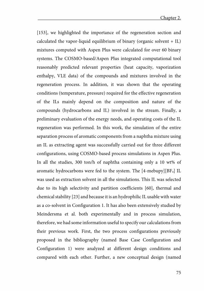
Chapter 2.
75
[153], we highlighted the importance of the regeneration section and
calculated the vapor-liquid equilibrium of binary (organic solvent + IL)
mixtures computed with Aspen Plus were calculated for over 60 binary
systems. The COSMO-based/Aspen Plus integrated computational tool
reasonably predicted relevant properties (heat capacity, vaporization
enthalpy, VLE data) of the compounds and mixtures involved in the
regeneration process. In addition, it was shown that the operating
conditions (temperature, pressure) required for the effective regeneration
of the ILs mainly depend on the composition and nature of the
compounds (hydrocarbons and IL) involved in the stream. Finally, a
preliminary evaluation of the energy needs, and operating costs of the IL
regeneration was performed. In this work, the simulation of the entire
separation process of aromatic components from a naphtha mixture using
an IL as extracting agent was successfully carried out for three different
configurations, using COSMO-based process simulations in Aspen Plus.
In all the studies, 300 ton/h of naphtha containing only a 10 wt% of
aromatic hydrocarbons were fed to the system. The [4-mebupy][BF4] IL
was used as extraction solvent in all the simulations. This IL was selected
due to its high selectivity and partition coefficients [60], thermal and
chemical stability [23] and because it is an hydrophilic IL usable with water
as a co-solvent in Configuration 1. It has also been extensively studied by
Meindersma et al. both experimentally and in process simulation,
therefore, we had some information useful to specify our calculations from
their previous work. First, the two process configurations previously
proposed in the bibliography (named Base Case Configuration and
Configuration 1) were analyzed at different design conditions and
compared with each other. Further, a new conceptual design (named
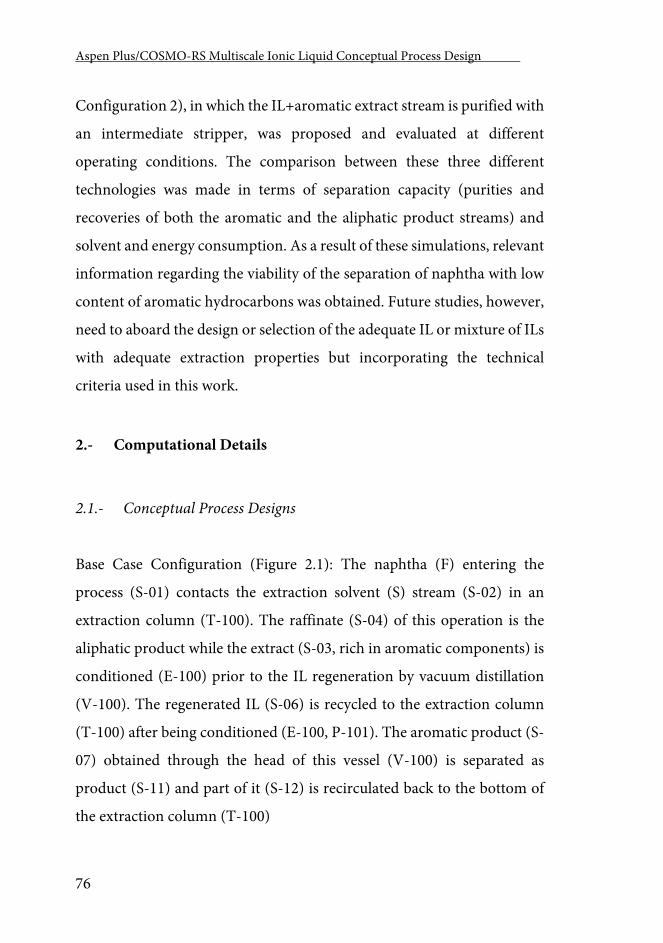
Aspen Plus/COSMO-RS Multiscale Ionic Liquid Conceptual Process Design .
76
Configuration 2), in which the IL+aromatic extract stream is purified with
an intermediate stripper, was proposed and evaluated at different
operating conditions. The comparison between these three different
technologies was made in terms of separation capacity (purities and
recoveries of both the aromatic and the aliphatic product streams) and
solvent and energy consumption. As a result of these simulations, relevant
information regarding the viability of the separation of naphtha with low
content of aromatic hydrocarbons was obtained. Future studies, however,
need to aboard the design or selection of the adequate IL or mixture of ILs
with adequate extraction properties but incorporating the technical
criteria used in this work.
2.- Computational Details
2.1.- Conceptual Process Designs
Base Case Configuration (Figure 2.1): The naphtha (F) entering the
process (S-01) contacts the extraction solvent (S) stream (S-02) in an
extraction column (T-100). The raffinate (S-04) of this operation is the
aliphatic product while the extract (S-03, rich in aromatic components) is
conditioned (E-100) prior to the IL regeneration by vacuum distillation
(V-100). The regenerated IL (S-06) is recycled to the extraction column
(T-100) after being conditioned (E-100, P-101). The aromatic product (S-
07) obtained through the head of this vessel (V-100) is separated as
product (S-11) and part of it (S-12) is recirculated back to the bottom of
the extraction column (T-100)
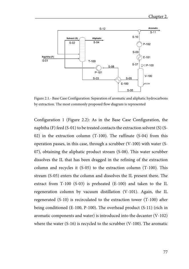
Chapter 2.
77
Figure 2.1.- Base Case Configuration: Separation of aromatic and aliphatic hydrocarbons by extraction. The most commonly proposed flow diagram is represented
Configuration 1 (Figure 2.2): As in the Base Case Configuration, the
naphtha (F) feed (S-01) to be treated contacts the extraction solvent (S) (S-
02) in the extraction column (T-100). The raffinate (S-04) from this
operation passes, in this case, through a scrubber (V-100) with water (S-
07), obtaining the aliphatic product stream (S-08). This water scrubber
dissolves the IL that has been dragged in the refining of the extraction
column and recycles it (S-05) to the extraction column (T-100). This
stream (S-05) enters the column and dissolves the IL present there. The
extract from T-100 (S-03) is preheated (E-100) and taken to the IL
regeneration column by vacuum distillation (V-101). Again, the IL
regenerated (S-10) is recirculated to the extraction tower (T-100) after
being conditioned (E-100, P-100). The overhead product (S-11) (rich in
aromatic components and water) is introduced into the decanter (V-102)
where the water (S-16) is recycled to the scrubber (V-100). The aromatic
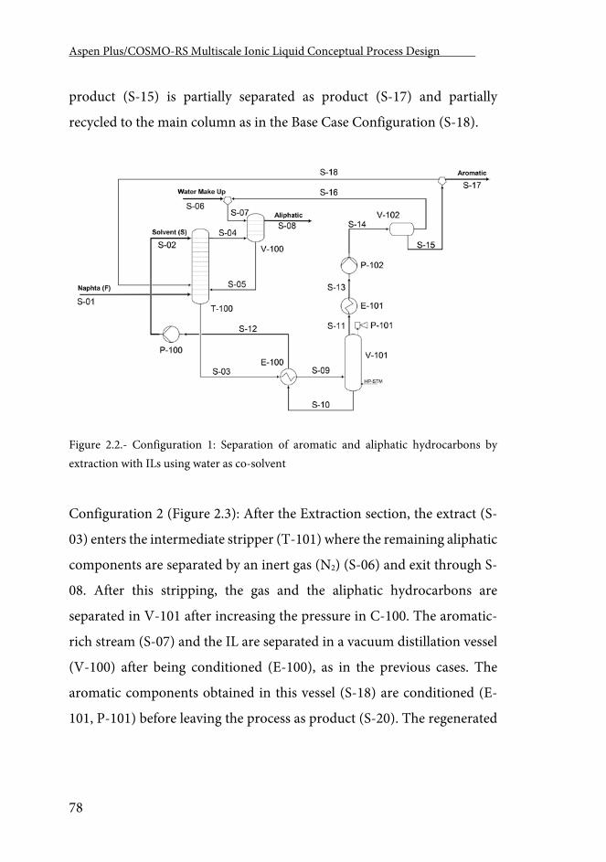
Aspen Plus/COSMO-RS Multiscale Ionic Liquid Conceptual Process Design .
78
product (S-15) is partially separated as product (S-17) and partially
recycled to the main column as in the Base Case Configuration (S-18).
Figure 2.2.- Configuration 1: Separation of aromatic and aliphatic hydrocarbons by extraction with ILs using water as co-solvent
Configuration 2 (Figure 2.3): After the Extraction section, the extract (S-
03) enters the intermediate stripper (T-101) where the remaining aliphatic
components are separated by an inert gas (N2) (S-06) and exit through S-
08. After this stripping, the gas and the aliphatic hydrocarbons are
separated in V-101 after increasing the pressure in C-100. The aromatic-
rich stream (S-07) and the IL are separated in a vacuum distillation vessel
(V-100) after being conditioned (E-100), as in the previous cases. The
aromatic components obtained in this vessel (S-18) are conditioned (E-
101, P-101) before leaving the process as product (S-20). The regenerated
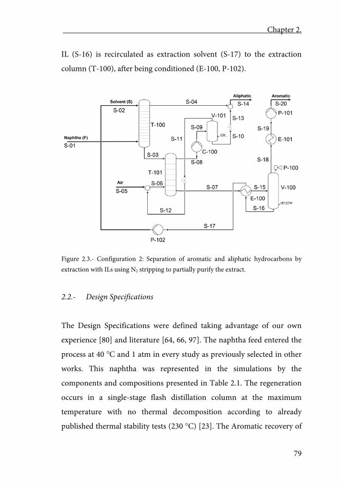
Chapter 2.
79
IL (S-16) is recirculated as extraction solvent (S-17) to the extraction
column (T-100), after being conditioned (E-100, P-102).
Figure 2.3.- Configuration 2: Separation of aromatic and aliphatic hydrocarbons by extraction with ILs using N2 stripping to partially purify the extract.
2.2.- Design Specifications
The Design Specifications were defined taking advantage of our own
experience [80] and literature [64, 66, 97]. The naphtha feed entered the
process at 40 C and 1 atm in every study as previously selected in other
works. This naphtha was represented in the simulations by the
components and compositions presented in Table 2.1. The regeneration
occurs in a single-stage flash distillation column at the maximum
temperature with no thermal decomposition according to already
published thermal stability tests (230 C) [23]. The Aromatic recovery of
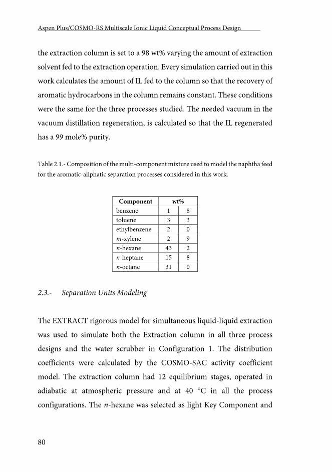
Aspen Plus/COSMO-RS Multiscale Ionic Liquid Conceptual Process Design .
80
the extraction column is set to a 98 wt% varying the amount of extraction
solvent fed to the extraction operation. Every simulation carried out in this
work calculates the amount of IL fed to the column so that the recovery of
aromatic hydrocarbons in the column remains constant. These conditions
were the same for the three processes studied. The needed vacuum in the
vacuum distillation regeneration, is calculated so that the IL regenerated
has a 99 mole% purity.
Table 2.1.- Composition of the multi-component mixture used to model the naphtha feed for the aromatic-aliphatic separation processes considered in this work.
Component wt% benzene 1 8 toluene 3 3 ethylbenzene 2 0 m-xylene 2 9 n-hexane 43 2 n-heptane 15 8 n-octane 31 0
2.3.- Separation Units Modeling
The EXTRACT rigorous model for simultaneous liquid-liquid extraction
was used to simulate both the Extraction column in all three process
designs and the water scrubber in Configuration 1. The distribution
coefficients were calculated by the COSMO-SAC activity coefficient
model. The extraction column had 12 equilibrium stages, operated in
adiabatic at atmospheric pressure and at 40 C in all the process
configurations. The n-hexane was selected as light Key Component and
Chapter 2.
81
the IL as the heavy Key Component. The water scrubber had 2 stages,
operated at 40 C and 1 bar as the extraction column so that the shared
streams did not need conditioning between operations. The vacuum
distillation was modeled using the FLASH2 Aspen Plus model. It
evaporates the aromatic hydrocarbons (and the remaining aliphatic part)
from the Extract of the main column whether it arrives to the flash drum
pre-purified Configuration 2) or not (Base Case Configuration). In these
simulations, the operation temperature corresponds to the maximum
temperature allowed by the IL without suffering decomposition (230 C)
[23] The stripper was simulated with the RADFRAC model as
implemented in Aspen Plus. The RADFRAC model is a rigorous model
for simulating all types of multistage vapor-liquid fractioning operations.
The stripper was modeled with 5 stages, only handles vapor-liquid
equilibrium (as no water which could create a second liquid phase is
present in the system), operates at 3 bars and at 40 C (the same
temperature of the extract that enters the column).
2.4.- Sensitivity Analysis
In the Base Case Configuration, the aromatic fraction recirculated to the
extraction column was the only process variable varied. In order to do so,
the split fraction was varied from 10 wt% to 90 wt% of the total inlet flow
to the splitter. In Configuration 1, the amount of water included in the
system was varied from 20 to 150 ton/h. In Configuration 2, the amount
of N2 injected in the system is varied from 20 to 80 tons/h.
Aspen Plus/COSMO-RS Multiscale Ionic Liquid Conceptual Process Design .
82
3.- Results and Discussion
3.1.- Base Case Configuration
The Base Case Configuration process of the extraction of aromatics from
a real-like naphtha feed using [4-mebupy][BF4] IL as extraction solvent
(Figure 2.1) was modeled, including the extraction tower, vacuum
distillation column, three pumps and, one 1-way and one 2-way heat
exchangers. Table A_ 1 (Appendices) collects the temperature, pressure
and component mass flow of the most important streams of this model as
well as its basic enthalpy balance. The Base Case Configuration is a
comparatively complex model if we take into account the process
simulations of systems involving ILs published in literature [153, 162, 182,
243]. This simulation includes two recycle loops that make the
convergence more complex as both operations stay connected having
interdependent results. One of these loops consists of the IL regenerated
(S-08) from the vacuum distillation column (V-100) and the other is a
fraction (S-12) of the aromatic product separated in V-100 (S-07). S-12 is
recycled in order to enrich the bottom of the extraction column (T-100)
in aromatic products improving separation. All the results present in
Table A_ 2 (Appendices) were obtained fixing a 90 wt% aromatic product
recirculation to the extraction tower. As a result, the required molar
solvent to feed ratio (S/F) was 2.1 (1,599 ton/h of [4-mebupy][BF4], in
order to obtain the required 98 wt% recovery in the extraction column.
This value is very close to those previously proposed in literature [64].
With this process configuration a raffinate (S-04) with a purity of 94 wt%
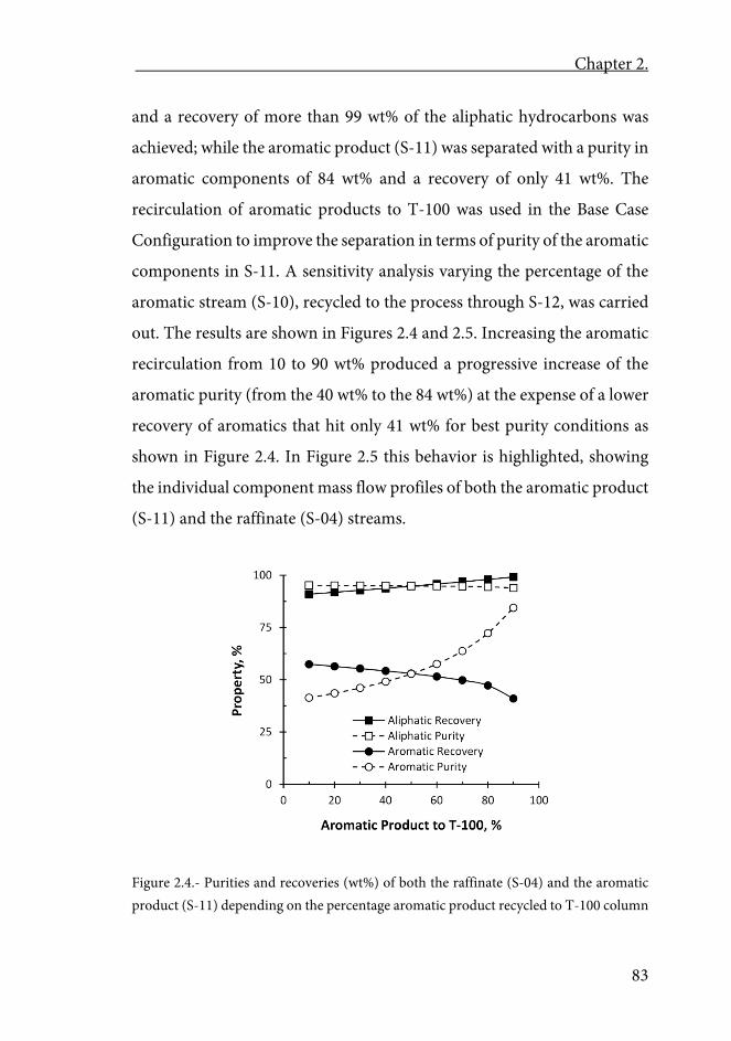
Chapter 2.
83
and a recovery of more than 99 wt% of the aliphatic hydrocarbons was
achieved; while the aromatic product (S-11) was separated with a purity in
aromatic components of 84 wt% and a recovery of only 41 wt%. The
recirculation of aromatic products to T-100 was used in the Base Case
Configuration to improve the separation in terms of purity of the aromatic
components in S-11. A sensitivity analysis varying the percentage of the
aromatic stream (S-10), recycled to the process through S-12, was carried
out. The results are shown in Figures 2.4 and 2.5. Increasing the aromatic
recirculation from 10 to 90 wt% produced a progressive increase of the
aromatic purity (from the 40 wt% to the 84 wt%) at the expense of a lower
recovery of aromatics that hit only 41 wt% for best purity conditions as
shown in Figure 2.4. In Figure 2.5 this behavior is highlighted, showing
the individual component mass flow profiles of both the aromatic product
(S-11) and the raffinate (S-04) streams.
Figure 2.4.- Purities and recoveries (wt%) of both the raffinate (S-04) and the aromatic product (S-11) depending on the percentage aromatic product recycled to T-100 column
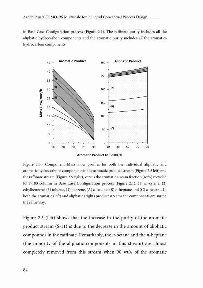
Aspen Plus/COSMO-RS Multiscale Ionic Liquid Conceptual Process Design .
84
in Base Case Configuration process (Figure 2.1). The raffinate purity includes all the aliphatic hydrocarbon components and the aromatic purity includes all the aromatics hydrocarbon components
Figure 2.5.- Component Mass Flow profiles for both the individual aliphatic and aromatic hydrocarbons components in the aromatic product stream (Figure 2.5 left) and the raffinate stream (Figure 2.5 right), versus the aromatic stream fraction (wt%) recycled to T-100 column in Base Case Configuration process (Figure 2.1). (1) m-xylene, (2) ethylbenzene, (3) toluene, (4) benzene, (A) n-octane, (B) n-heptane and (C) n-hexane. In both the aromatic (left) and aliphatic (right) product streams the components are sorted the same way.
Figure 2.5 (left) shows that the increase in the purity of the aromatic
product stream (S-11) is due to the decrease in the amount of aliphatic
compounds in the raffinate. Remarkably, the n-octane and the n-heptane
(the minority of the aliphatic components in this stream) are almost
completely removed from this stream when 90 wt% of the aromatic
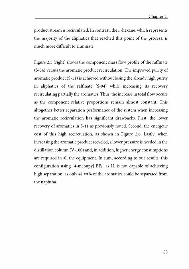
Chapter 2.
85
product stream is recirculated. In contrast, the n-hexane, which represents
the majority of the aliphatics that reached this point of the process, is
much more difficult to eliminate.
Figure 2.5 (right) shows the component mass flow profile of the raffinate
(S-04) versus the aromatic product recirculation. The improved purity of
aromatic product (S-11) is achieved without losing the already high purity
in aliphatics of the raffinate (S-04) while increasing its recovery
recirculating partially the aromatics. Thus, the increase in total flow occurs
as the component relative proportions remain almost constant. This
altogether better separation performance of the system when increasing
the aromatic recirculation has significant drawbacks. First, the lower
recovery of aromatics in S-11 as previously noted. Second, the energetic
cost of this high recirculation, as shown in Figure 2.6. Lastly, when
increasing the aromatic product recycled, a lower pressure is needed in the
distillation column (V-100) and, in addition, higher energy consumptions
are required in all the equipment. In sum, according to our results, this
configuration using [4-mebupy][BF4] as IL is not capable of achieving
high separation, as only 41 wt% of the aromatics could be separated from
the naphtha.
Aspen Plus/COSMO-RS Multiscale Ionic Liquid Conceptual Process Design .
86
Figure 2.6.- Total energy cost and working pressure of the vacuum distillation column (V-100) vs the percentage of aromatic product recirculated to the extraction tower T-100 in Base Case Configuration process (Figure 2.1).
Configuration 1
In this case, a more complex model was simulated following the proposal
of Meindersma et al. [97] for a potential separation process of aromatic +
aliphatic mixtures based on ILs. The simulation of this system presented a
huge challenge since the addition of water implied that additional ternary
liquid-liquid equilibria needed to be estimated. The water scrubber
inclusion proposed by Meindersma et al. [97] is very significant because it
introduces water into the system with a double objective: first, retains the
remaining IL that leaves the extraction tower’s overhead and, second,
makes the solvent phase inside the tower more polar, increasing the
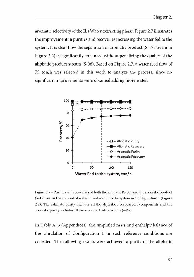
Chapter 2.
87
aromatic selectivity of the IL+Water extracting phase. Figure 2.7 illustrates
the improvement in purities and recoveries increasing the water fed to the
system. It is clear how the separation of aromatic product (S-17 stream in
Figure 2.2) is significantly enhanced without penalizing the quality of the
aliphatic product stream (S-08). Based on Figure 2.7, a water feed flow of
75 ton/h was selected in this work to analyze the process, since no
significant improvements were obtained adding more water.
Figure 2.7.- Purities and recoveries of both the aliphatic (S-08) and the aromatic product (S-17) versus the amount of water introduced into the system in Configuration 1 (Figure 2.2). The raffinate purity includes all the aliphatic hydrocarbon components and the aromatic purity includes all the aromatic hydrocarbons (wt%).
In Table A_3 (Appendices), the simplified mass and enthalpy balance of
the simulation of Configuration 1 in such reference conditions are
collected. The following results were achieved: a purity of the aliphatic
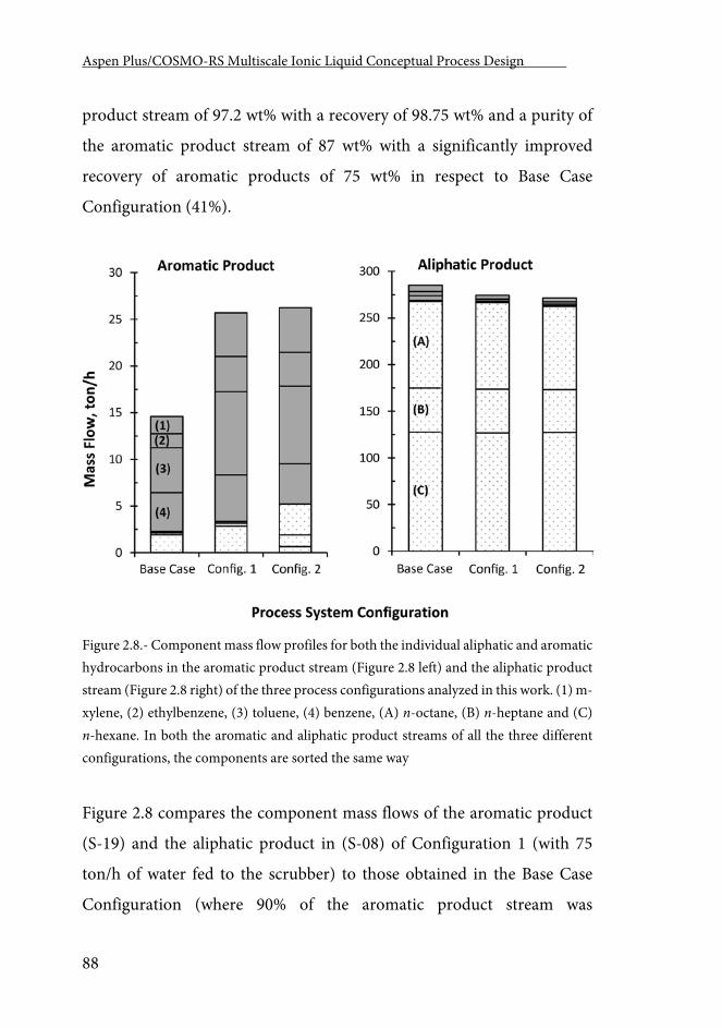
Aspen Plus/COSMO-RS Multiscale Ionic Liquid Conceptual Process Design .
88
product stream of 97.2 wt% with a recovery of 98.75 wt% and a purity of
the aromatic product stream of 87 wt% with a significantly improved
recovery of aromatic products of 75 wt% in respect to Base Case
Configuration (41%).
Figure 2.8.- Component mass flow profiles for both the individual aliphatic and aromatic hydrocarbons in the aromatic product stream (Figure 2.8 left) and the aliphatic product stream (Figure 2.8 right) of the three process configurations analyzed in this work. (1) m-xylene, (2) ethylbenzene, (3) toluene, (4) benzene, (A) n-octane, (B) n-heptane and (C) n-hexane. In both the aromatic and aliphatic product streams of all the three different configurations, the components are sorted the same way
Figure 2.8 compares the component mass flows of the aromatic product
(S-19) and the aliphatic product in (S-08) of Configuration 1 (with 75
ton/h of water fed to the scrubber) to those obtained in the Base Case
Configuration (where 90% of the aromatic product stream was
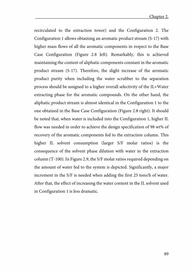
Chapter 2.
89
recirculated to the extraction tower) and the Configuration 2. The
Configuration 1 allows obtaining an aromatic product stream (S-17) with
higher mass flows of all the aromatic components in respect to the Base
Case Configuration (Figure 2.8 left). Remarkably, this is achieved
maintaining the content of aliphatic components constant in the aromatic
product stream (S-17). Therefore, the slight increase of the aromatic
product purity when including the water scrubber to the separation
process should be assigned to a higher overall selectivity of the IL+Water
extracting phase for the aromatic compounds. On the other hand, the
aliphatic product stream is almost identical in the Configuration 1 to the
one obtained in the Base Case Configuration (Figure 2.8 right). It should
be noted that, when water is included into the Configuration 1, higher IL
flow was needed in order to achieve the design specification of 98 wt% of
recovery of the aromatic components fed to the extraction column. This
higher IL solvent consumption (larger S/F molar ratios) is the
consequence of the solvent phase dilution with water in the extraction
column (T-100). In Figure 2.9, the S/F molar ratios required depending on
the amount of water fed to the system is depicted. Significantly, a major
increment in the S/F is needed when adding the first 25 tons/h of water.
After that, the effect of increasing the water content in the IL solvent used
in Configuration 1 is less dramatic.
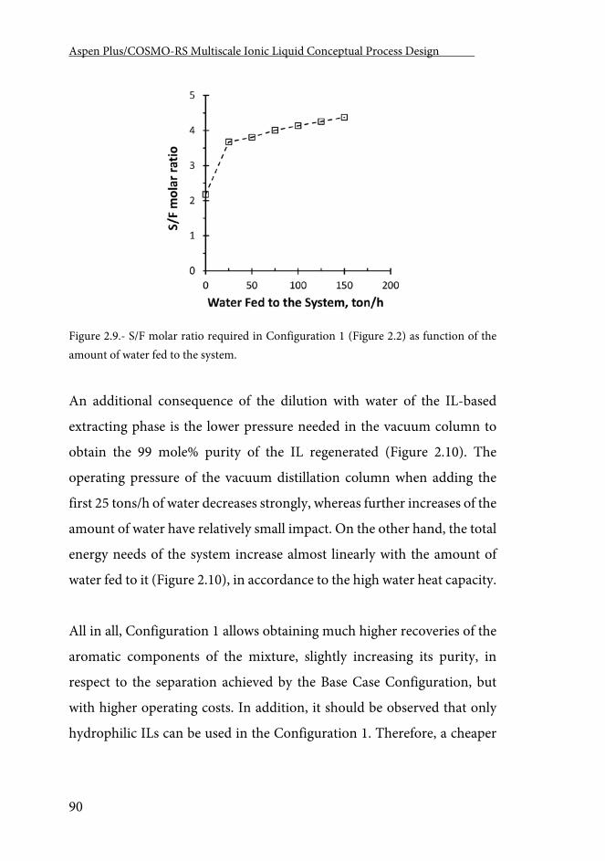
Aspen Plus/COSMO-RS Multiscale Ionic Liquid Conceptual Process Design .
90
Figure 2.9.- S/F molar ratio required in Configuration 1 (Figure 2.2) as function of the amount of water fed to the system.
An additional consequence of the dilution with water of the IL-based
extracting phase is the lower pressure needed in the vacuum column to
obtain the 99 mole% purity of the IL regenerated (Figure 2.10). The
operating pressure of the vacuum distillation column when adding the
first 25 tons/h of water decreases strongly, whereas further increases of the
amount of water have relatively small impact. On the other hand, the total
energy needs of the system increase almost linearly with the amount of
water fed to it (Figure 2.10), in accordance to the high water heat capacity.
All in all, Configuration 1 allows obtaining much higher recoveries of the
aromatic components of the mixture, slightly increasing its purity, in
respect to the separation achieved by the Base Case Configuration, but
with higher operating costs. In addition, it should be observed that only
hydrophilic ILs can be used in the Configuration 1. Therefore, a cheaper
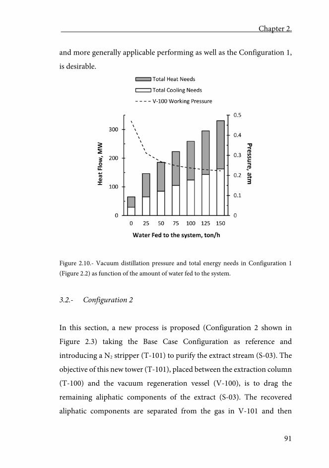
Chapter 2.
91
and more generally applicable performing as well as the Configuration 1,
is desirable.
Figure 2.10.- Vacuum distillation pressure and total energy needs in Configuration 1 (Figure 2.2) as function of the amount of water fed to the system.
3.2.- Configuration 2
In this section, a new process is proposed (Configuration 2 shown in
Figure 2.3) taking the Base Case Configuration as reference and
introducing a N2 stripper (T-101) to purify the extract stream (S-03). The
objective of this new tower (T-101), placed between the extraction column
(T-100) and the vacuum regeneration vessel (V-100), is to drag the
remaining aliphatic components of the extract (S-03). The recovered
aliphatic components are separated from the gas in V-101 and then
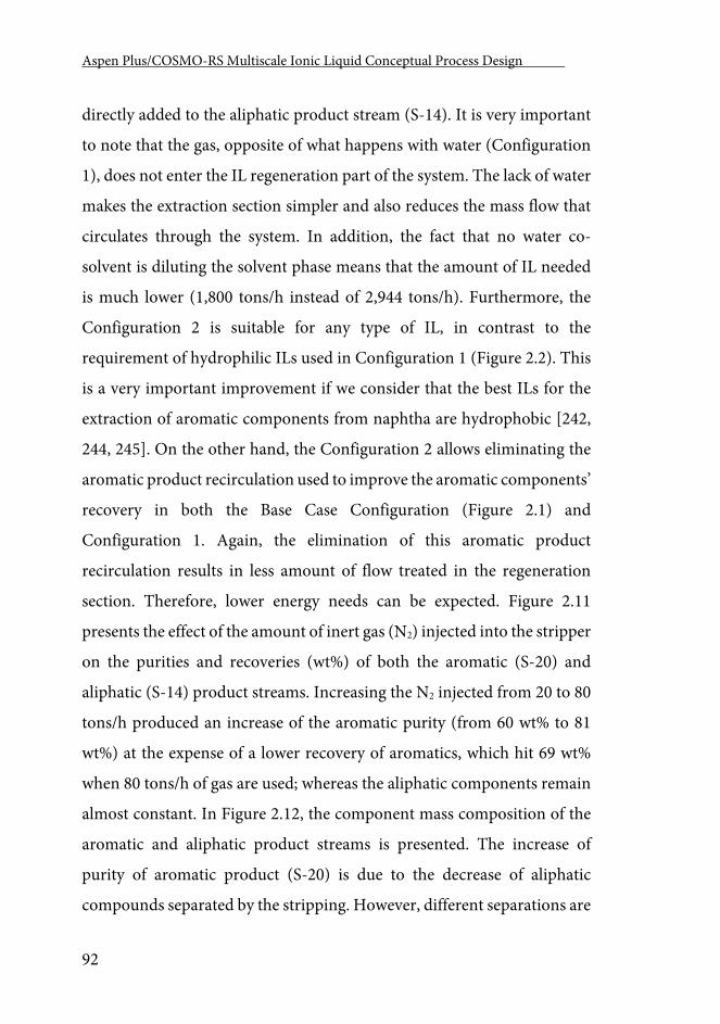
Aspen Plus/COSMO-RS Multiscale Ionic Liquid Conceptual Process Design .
92
directly added to the aliphatic product stream (S-14). It is very important
to note that the gas, opposite of what happens with water (Configuration
1), does not enter the IL regeneration part of the system. The lack of water
makes the extraction section simpler and also reduces the mass flow that
circulates through the system. In addition, the fact that no water co-
solvent is diluting the solvent phase means that the amount of IL needed
is much lower (1,800 tons/h instead of 2,944 tons/h). Furthermore, the
Configuration 2 is suitable for any type of IL, in contrast to the
requirement of hydrophilic ILs used in Configuration 1 (Figure 2.2). This
is a very important improvement if we consider that the best ILs for the
extraction of aromatic components from naphtha are hydrophobic [242,
244, 245]. On the other hand, the Configuration 2 allows eliminating the
aromatic product recirculation used to improve the aromatic components’
recovery in both the Base Case Configuration (Figure 2.1) and
Configuration 1. Again, the elimination of this aromatic product
recirculation results in less amount of flow treated in the regeneration
section. Therefore, lower energy needs can be expected. Figure 2.11
presents the effect of the amount of inert gas (N2) injected into the stripper
on the purities and recoveries (wt%) of both the aromatic (S-20) and
aliphatic (S-14) product streams. Increasing the N2 injected from 20 to 80
tons/h produced an increase of the aromatic purity (from 60 wt% to 81
wt%) at the expense of a lower recovery of aromatics, which hit 69 wt%
when 80 tons/h of gas are used; whereas the aliphatic components remain
almost constant. In Figure 2.12, the component mass composition of the
aromatic and aliphatic product streams is presented. The increase of
purity of aromatic product (S-20) is due to the decrease of aliphatic
compounds separated by the stripping. However, different separations are
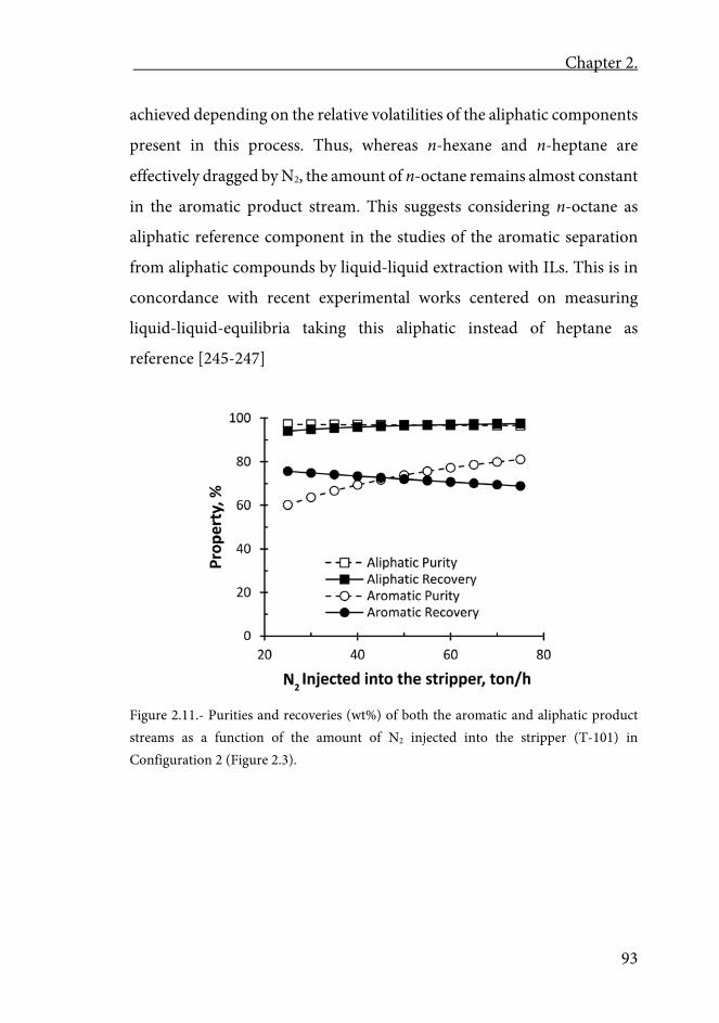
Chapter 2.
93
achieved depending on the relative volatilities of the aliphatic components
present in this process. Thus, whereas n-hexane and n-heptane are
effectively dragged by N2, the amount of n-octane remains almost constant
in the aromatic product stream. This suggests considering n-octane as
aliphatic reference component in the studies of the aromatic separation
from aliphatic compounds by liquid-liquid extraction with ILs. This is in
concordance with recent experimental works centered on measuring
liquid-liquid-equilibria taking this aliphatic instead of heptane as
reference [245-247]
Figure 2.11.- Purities and recoveries (wt%) of both the aromatic and aliphatic product streams as a function of the amount of N2 injected into the stripper (T-101) in Configuration 2 (Figure 2.3).
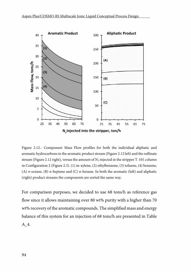
Aspen Plus/COSMO-RS Multiscale Ionic Liquid Conceptual Process Design .
94
Figure 2.12.- Component Mass Flow profiles for both the individual aliphatic and aromatic hydrocarbons in the aromatic product stream (Figure 2.12 left) and the raffinate stream (Figure 2.12 right), versus the amount of N2 injected in the stripper T-101 column in Configuration 2 (Figure 2.3). (1) m-xylene, (2) ethylbenzene, (3) toluene, (4) benzene, (A) n-octane, (B) n-heptane and (C) n-hexane. In both the aromatic (left) and aliphatic (right) product streams the components are sorted the same way.
For comparison purposes, we decided to use 68 tons/h as reference gas
flow since it allows maintaining over 80 wt% purity with a higher than 70
wt% recovery of the aromatic compounds. The simplified mass and energy
balance of this system for an injection of 68 tons/h are presented in Table
A_4.
Chapter 2.
95
4.- Overview
In Figure 2.8 the separation capacities of the three different configurations
for aromatic-aliphatic separation using IL as extraction solvent was
compared. It may be observed that the separation capacity of
Configuration 2 is better than the Base Case Configuration: the aromatic
recovery improves greatly (from 41 wt% to 70 wt%) whereas the purity of
aromatic product presents similar values (84 wt% in the Base Case
Configuration and 81 wt% in the Configuration 2). Configuration 2 (with
the intermediate stripping) and Configuration 1 (with water scrubber)
present relatively close aromatic separation capacity, with slightly better
performance in Configuration 1 (81 wt% purity instead of 87 wt% and 70
wt% of recovery instead of 75 wt%). Very similar results are obtained
regarding the aliphatic product stream in the three configurations.
However, this lower separation capacity of Configuration 2 is
compensated by a much lower energy consumption, as is shown in Figure
2.13, where the total energy needs (taking into account all the heat and
pressure changers) of the three process system configurations are
represented. These results show that the vast differences in mass flows
used in the different processes, previously stated, are translated to energy
costs. The proposed Configuration 2 does not need the aromatic
recirculation (present in both previous cases) and no water was included
(as in Configuration 1). Consequently, Configuration 2 is the
configuration that had the least amount of mass flow entering the
regeneration section where IL is separated by vacuum distillation at 230
C. It implies that the total energy needs in Configuration 2 represent 30%
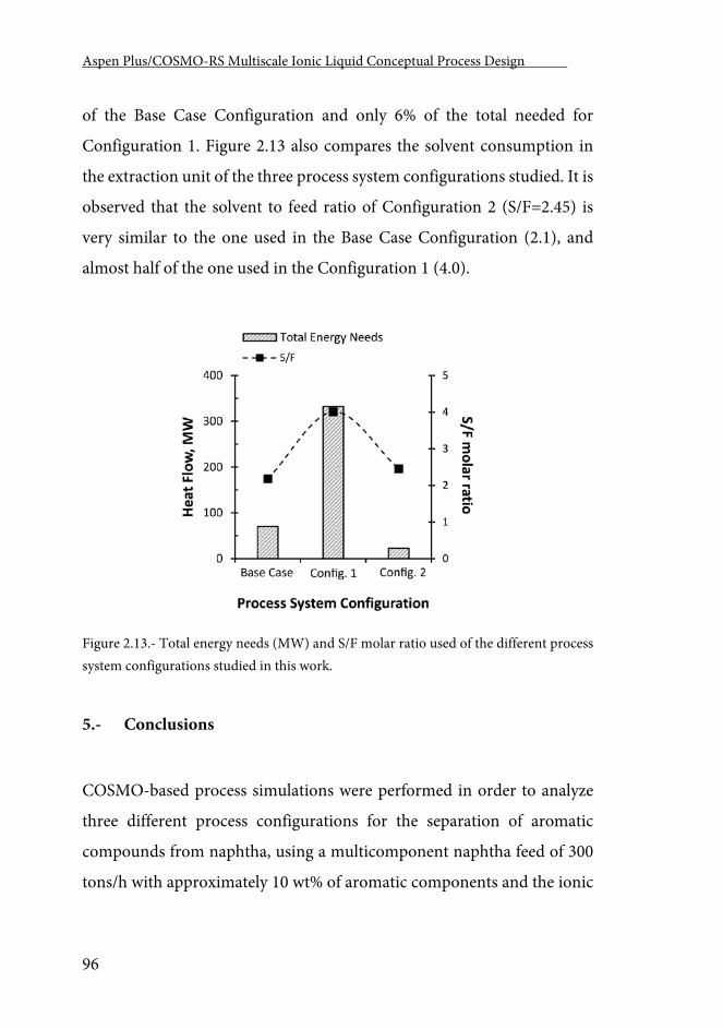
Aspen Plus/COSMO-RS Multiscale Ionic Liquid Conceptual Process Design .
96
of the Base Case Configuration and only 6% of the total needed for
Configuration 1. Figure 2.13 also compares the solvent consumption in
the extraction unit of the three process system configurations studied. It is
observed that the solvent to feed ratio of Configuration 2 (S/F=2.45) is
very similar to the one used in the Base Case Configuration (2.1), and
almost half of the one used in the Configuration 1 (4.0).
Figure 2.13.- Total energy needs (MW) and S/F molar ratio used of the different process system configurations studied in this work.
5.- Conclusions
COSMO-based process simulations were performed in order to analyze
three different process configurations for the separation of aromatic
compounds from naphtha, using a multicomponent naphtha feed of 300
tons/h with approximately 10 wt% of aromatic components and the ionic
Chapter 2.
97
liquid 4-methyl-N-butylpyridinium tetrafluoroborate ionic liquid as the
extracting agent. Firstly, a conventional extraction + regeneration process
(Base Case Configuration), very commonly proposed in literature, was
studied. It consists of the extraction column connected to a regeneration
section where the IL is separated from the rest of the components present
in the Extract by vacuum distillation. After the separation, part of the
aromatic components is recirculated to the extraction column in order to
enhance the separation. 90 wt% of the aromatic product stream was
selected as the better recirculation split fraction. An aromatic product
stream with a purity of 84 wt% was obtained but only 41 wt% of the
aromatic components were recovered. In order to obtain these results
1,559 ton/h of IL were used as extraction solvents. This represented a
molar solvent-to-feed ratio of 2.1. The total energy consumed taking into
account the amount of energy consumed by pump, and cooling and
heating 1-side heat exchangers was 63 MW. The second process
(Configuration 1) adds a water scrubber to the previous configuration that
injects water as co-solvent into the system. This addition demonstrated to
be highly effective as it dramatically enhanced the separation. Adding 75
tons/h of water, it was possible to recover the 75 wt% of the aromatic
hydrocarbons with a purity of 87 wt%. In order to do so, however, it
needed more solvent (2,944 tons/h) and energy (more than 300 MW)
consumption. Lastly, a new process (Configuration 2), proposed for the
first time in this paper, was analyzed and compared to the previous ones.
The obtained aromatic product contains 70 wt% of the aromatic
components of the naphtha fed to the system with an overall purity of 81
wt%. It requires 1,800 tons/h of recycled IL and a total energy
consumption of 26 MW, which corresponds to 1/3 of the energy needed
Aspen Plus/COSMO-RS Multiscale Ionic Liquid Conceptual Process Design .
98
in the Base Case Configuration and only the 6% of the energy needed in
the Configuration 1. Based on the conceptual engineering, we selected
Configuration 2 as an interesting alternative to others previously reported
in literature (the Base Case Configuration and Configuration 1). In the
future, we will work towards the optimization, and the technical and safety
analysis of Configuration 2, including, the design/selection of a more
adequate IL or mixture of ILs, the optimization of the operating
conditions, and the sizing and capital cost estimation of the equipment.
Chapter 3 Ionic liquids as entrainers for the separation of aromatic-
aliphatic hydrocarbon mixtures by extractive distillation
Chapter 3
101
Chapter 3
Ionic liquids as entrainers for the separation of aromatic-aliphatic hydrocarbon mixtures by extractive distillation
Abstract
The conceptual engineering of a new process proposed for the aromatic-
aliphatic separation from naphtha has been developed based on extractive
distillation using the 1-ethyl-3-methyl imidazolium dicyanamide
[emim][DCA] ionic liquid as entrainer. Process designs, and simulations
have been carried out with a computer-aided methodology recently
developed in our group that integrates molecular modeling and process
simulation via COSMO-based thermodynamic models in Aspen Plus. The
computational analysis has been performed for two different
multicomponent real-like naphtha models: a low aromatic content
naphtha (10 wt%) and a naphtha with a high aromatic content (90 wt%).
A sensitivity analysis with 8200 different extractive distillation column
designs has been carried out varying the ionic liquid solvent to feed ratio,
reflux ratio, number of stages and feed stage, in order to optimize the
column design minimizing the reboiler duty and maximizing the
throughput. In the low aromatic content naphtha, the results show that
similar separation efficiencies to liquid-liquid extraction may be achieved
by extractive distillation, requiring lower solvent to feed ratios but higher
energy consumptions. For the high aromatic content naphtha, good
separation performance is obtained with a significant reduction of the
Aspen Plus/COSMO-RS Multiscale Ionic Liquid Conceptual Process Design .
102
energy required per ton of naphtha fed to the system in comparison with
the separation by liquid-liquid extraction. To evaluate the behavior of the
process simulator using COSMOSAC, the classical NRTL thermodynamic
model, fitted using experimental vapor-liquid and liquid-liquid data, was
used to simulate the extractive distillation process for a simpler binary n-
heptane-toluene mixture. Similar results are obtained using COSMOSAC
and NRTL models for this binary aromatic-aliphatic mixture indicating
the reliability of the COSMOSAC-based simulations of more complex
multicomponent naphtha separation.
1.- Introduction
Separation of aromatic hydrocarbons from naphtha has a great interest for
the petrochemical industry [64, 96, 171]. On one side, aromatic
hydrocarbons represent an extra load for the naphtha crackers, negatively
affecting the process economy as additional operative and capital costs.
On other side, aromatic hydrocarbons have their own value as raw
materials, being further transformed in higher value-added products.
Several technologies have been developed for separating aromatic
hydrocarbons from aliphatic ones, mainly depending on the aromatic
content of the naphtha mixture. It is commonly accepted [64] that
separation processes based on liquid-liquid extraction are suitable for the
range of 20-65 wt% aromatic content, extractive distillation for naphtha
with an aromatic content of 65-90 wt% and azeotropic distillation for
higher aromatic content naphtha (>90 wt%). However, it is also frequent
Chapter 3
103
to find naphtha with aromatic contents lower than 20 wt%. This low
concentration range represents a technological challenge for the
petrochemical industry, but has received a relative limited attention.
The development of new technologies for the aromatic separation from
aliphatic hydrocarbons present in naphtha implies necessarily an adequate
solvent for the separation process used. A number of organic compounds
(usually polar species) have been evaluated as solvents in these processes
[64]: sulfolane, N-methyl pyrrolidine, N-formyl morpholine, ethylene
glycols or propylene carbonate. All in all, sulfolane has resulted the most
extensively used thanks to an UOP technology, which employs it as
extracting solvent. In this process, sulfolane has to be recovered from both
the extract and the raffinate after liquid-liquid extraction, which entails
high investment and energy costs [96]. Ionic liquids (ILs) are a novel
attractive candidate for this separation since Seddon in 1997 [93] reported
the great capacity of imidazolium ionic liquids to dissolve benzene.
Subsequently, large number of ILs of different families (imidazolium,
pyridinium, pyrrolidinium, ammonium, etc.) have been experimentally
evaluated as solvent for liquid-liquid extraction of benzene, toluene,
ethylbenzene or xylene from their binary mixtures with aliphatic
hydrocarbons [61-63, 98, 99, 101, 106, 173, 228, 230, 244, 248-268]. In
contrast, the vapor-liquid equilibria information of the aromatic +
aliphatic + ILs systems, needed to properly design the IL regeneration
(usually proposed to be carried out by flash distillation), have been by far
less studied [220, 241, 269-272]. These studies have been mainly centered
in thermodynamic criteria related to the corresponding operations,
whereas, unfortunately, technoeconomic considerations have been
Aspen Plus/COSMO-RS Multiscale Ionic Liquid Conceptual Process Design .
104
noticeably less taken into account. On the other hand, the development of
new processes to separate aromatic hydrocarbons from naphtha with ILs
has been limited until now due to the lack of thermodynamic, kinetic and
transport property data of multicomponent naphtha + IL systems,
required information to proceed with the design of both the individual
operations and the overall process. Thus, the existing experimental
information for those systems is mainly restricted to binary aromatic-
aliphatic mixtures, so the extrapolation to real naphtha requires of some
simplifications in order to describe multicomponent phase equilibria data.
In addition, the great amount of possible existing ILs (>300 commercial
and >106 synthesizable compounds)- whose solvent performance is
determined by both cationic and anionic features - certainly limits the
scope of the experimental screenings to design ILs with optimized
properties for extracting aromatic hydrocarbons from naphtha. As a
result, the first conceptual design of the process for the aromatic
separation from naphtha using ILs is relatively recent (2008) [64]. This
development was centered in a very low aromatic content naphtha
(around 10 wt%), using liquid-liquid extraction. This work was limited to
the extractive operation and it explicitly omitted modeling the vacuum
distillation, operation proposed to regenerate the IL. The authors justified
this decision due to the absence, in that moment, of sufficient
thermodynamic data conveniently elaborated to simulate the
corresponding VL separation with commercial process simulators such as
Aspen Plus. Recently, we have successfully applied a simulation strategy
for performing the conceptual design of both the individual operations
[80] and the complete process [163] to separate aromatic hydrocarbons
from low-aromatic content naphtha by liquid-liquid extraction using ILs.
Chapter 3
105
Our process development included the proposal and techno-economical
evaluation of different process configurations to, efficiently, separate
aromatic products and to regenerate the IL. A main contribution of these
works was the incorporation of multicomponent mixtures to model the
naphtha in the process simulations. This result was possible because of the
consistent application of a computational methodology that combines the
molecular modeling and the process simulation supported by the
COSMO-based thermodynamic models [153]. The COnductor-like
Screening Model for Real Solvents (COSMO-RS) [273], derived from
quantum chemical COSMO theory [274], predicts thermodynamic data
of fluid mixtures using molecular information of the individual
components. COSMO-RS have shown very good results in the prediction
of liquid-liquid equilibria of ternary mixtures aromatics + aliphatics + IL
[141, 207, 219, 275, 276]. In addition, some commercial flowsheeting
simulation software, such as Aspen Plus, have introduced a property
package where activity coefficients are computed using COSMO based
models, such as COSMO-RS or COSMO-SAC [212]. The successful
integration of predictive thermodynamic models, like COSMO-based
ones, into the property system of Aspen Plus and Aspen HYSYS allow
fruitfully overtaking the lack of information of naphtha-ILs mixtures. This
multiscale computational strategy has demonstrated excellent to be an
excellent tool capable of dealing with processes and operations involving
ILs and their mixtures with gases and organic molecular solvents [56, 153,
162, 215]. Recent studies [80, 163] demonstrated that liquid-liquid
extraction with ILs is a valid technological option to separate aromatic
hydrocarbons from low-aromatic content (up to 10 wt%) naphtha under
technical and economic criteria.
Aspen Plus/COSMO-RS Multiscale Ionic Liquid Conceptual Process Design .
106
In this work, the multiscale computational methodology is applied to the
conceptual design of a new process based on an extractive distillation
column (EDC) to separate aromatic hydrocarbons from naphtha, using an
IL as entrainer. The suitability of the extractive distillation technology for
separating aromatic compounds from naphtha was evaluated for two
multicomponent aliphatic-aromatic mixtures: a naphtha with low
aromatic content (10 wt%) and a naphtha with high aromatic content (90
wt%). The solvent 1-ethyl-3-methylimidazolium dicyanamide
([emim][DCA]) was selected as entrainer in the EDC because its great
influence over the relative volatility of aromatics-aliphatics mixtures [236,
242, 277, 278] and its high thermal stability (no significant degradation is
expected at temperatures below 200 C) [279]. First, the prediction
capability of COSMOSAC property package was validated comparing
calculated and experimental fluid phase equilibria (VLE and LLE) data of
the simple aromatic (toluene) + aliphatic (n-heptane) + IL
([emim][DCA]) ternary mixture, because of the lack of available
experimental data or reliable thermodynamic models for multicomponent
naphtha-IL systems. Then, the EDC operation is modeled using a
rigorous RADFRAC tray column, systematically analyzing the influence
of the number of theoretical stages, naphtha feed stage, reflux ratio, IL
solvent to feed ratio and distillate to feed ratio. All simulations modeled
the separation of the aromatic-aliphatic hydrocarbon in the EDC and the
IL regeneration by vacuum distillation. For the best designs, the
performance of EDC process with IL for the separation of aromatic from
naphtha was compared to those previously reported for liquid-liquid
Chapter 3
107
extraction with ILs, in terms of the recovery and purity of aliphatic and
aromatic products, solvent used and energy consumption.
Along with the main goal, in this work we have performed a deeper
validation of the computational strategy used. Beyond the needed
evaluation of the LLE and VLE predictive capability of the COSMO-based
methods, it is interesting to analyze their effects on the separation process
performance. For this purpose, we have modeled the separation by
extractive distillation of a simple toluene + n-heptane + [emim][DCA]
ternary mixture, using the thermodynamic estimations of both the
parametric NRTL model (whose interaction parameters were regressed
from experimental data) and the predictive COSMOSAC model (which
does not require experimental data). The comparison of the results
obtained using COSMOSAC and NRTL models for the aromatic +
aliphatic + IL ternary mixture provides indications of the reliability of the
COSMOSAC-based simulations with more complex multicomponent
naphtha + IL systems.
2.- Computational Details
2.1.- Process description
The process configuration studied in this work is shown in Figure 3.1.
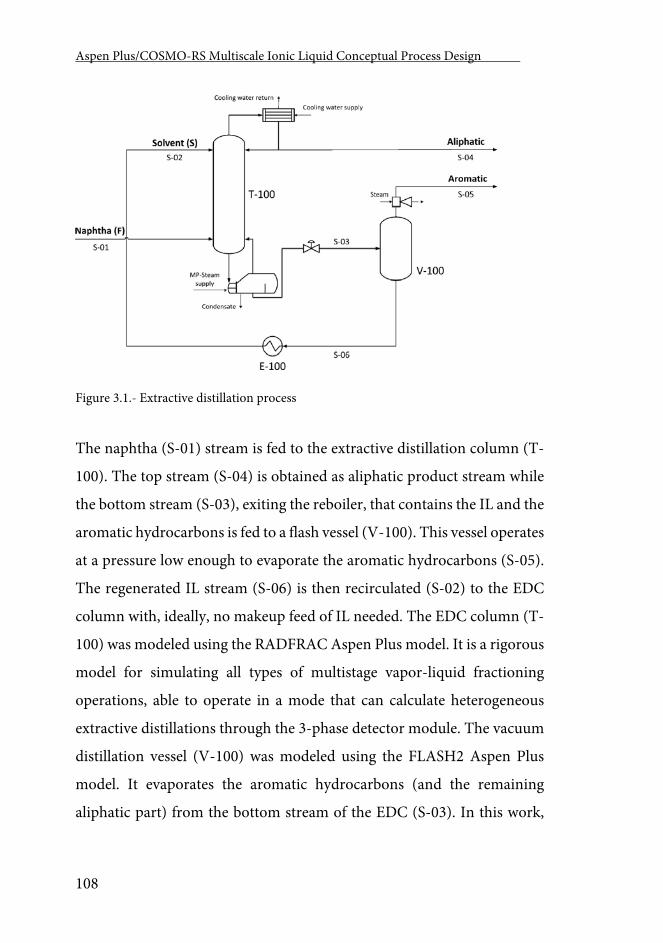
Aspen Plus/COSMO-RS Multiscale Ionic Liquid Conceptual Process Design .
108
Figure 3.1.- Extractive distillation process
The naphtha (S-01) stream is fed to the extractive distillation column (T-
100). The top stream (S-04) is obtained as aliphatic product stream while
the bottom stream (S-03), exiting the reboiler, that contains the IL and the
aromatic hydrocarbons is fed to a flash vessel (V-100). This vessel operates
at a pressure low enough to evaporate the aromatic hydrocarbons (S-05).
The regenerated IL stream (S-06) is then recirculated (S-02) to the EDC
column with, ideally, no makeup feed of IL needed. The EDC column (T-
100) was modeled using the RADFRAC Aspen Plus model. It is a rigorous
model for simulating all types of multistage vapor-liquid fractioning
operations, able to operate in a mode that can calculate heterogeneous
extractive distillations through the 3-phase detector module. The vacuum
distillation vessel (V-100) was modeled using the FLASH2 Aspen Plus
model. It evaporates the aromatic hydrocarbons (and the remaining
aliphatic part) from the bottom stream of the EDC (S-03). In this work,
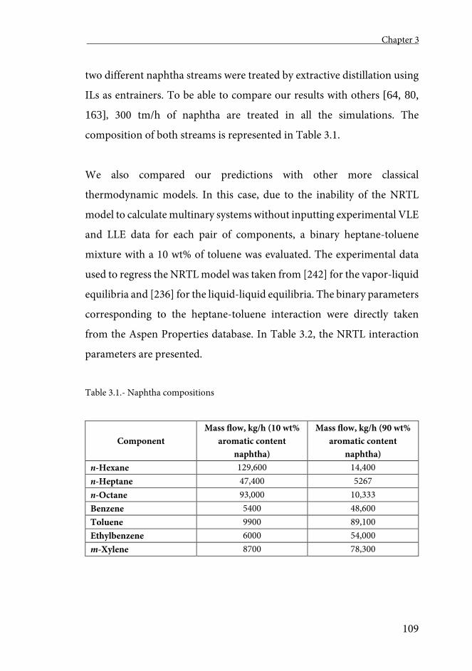
Chapter 3
109
two different naphtha streams were treated by extractive distillation using
ILs as entrainers. To be able to compare our results with others [64, 80,
163], 300 tm/h of naphtha are treated in all the simulations. The
composition of both streams is represented in Table 3.1.
We also compared our predictions with other more classical
thermodynamic models. In this case, due to the inability of the NRTL
model to calculate multinary systems without inputting experimental VLE
and LLE data for each pair of components, a binary heptane-toluene
mixture with a 10 wt% of toluene was evaluated. The experimental data
used to regress the NRTL model was taken from [242] for the vapor-liquid
equilibria and [236] for the liquid-liquid equilibria. The binary parameters
corresponding to the heptane-toluene interaction were directly taken
from the Aspen Properties database. In Table 3.2, the NRTL interaction
parameters are presented.
Table 3.1.- Naphtha compositions
Component Mass flow, kg/h (10 wt%
aromatic content naphtha)
Mass flow, kg/h (90 wt% aromatic content
naphtha) n-Hexane 129,600 14,400 n-Heptane 47,400 5267 n-Octane 93,000 10,333 Benzene 5400 48,600 Toluene 9900 89,100 Ethylbenzene 6000 54,000 m-Xylene 8700 78,300
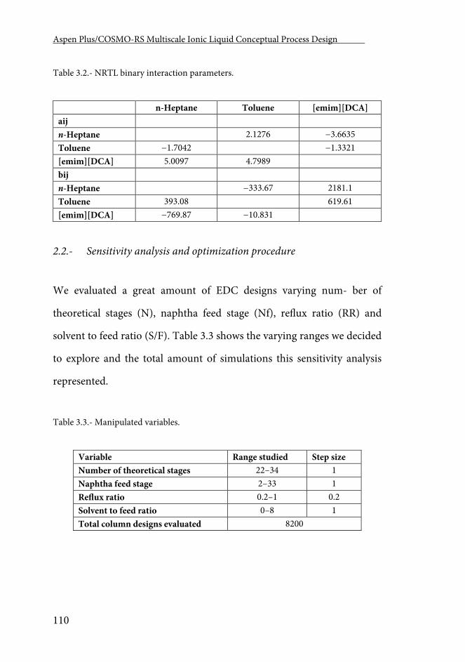
Aspen Plus/COSMO-RS Multiscale Ionic Liquid Conceptual Process Design .
110
Table 3.2.- NRTL binary interaction parameters.
n-Heptane Toluene [emim][DCA] aij n-Heptane 2.1276 −3.6635 Toluene −1.7042 −1.3321 [emim][DCA] 5.0097 4.7989 bij n-Heptane −333.67 2181.1 Toluene 393.08 619.61 [emim][DCA] −769.87 −10.831
2.2.- Sensitivity analysis and optimization procedure
We evaluated a great amount of EDC designs varying num- ber of
theoretical stages (N), naphtha feed stage (Nf), reflux ratio (RR) and
solvent to feed ratio (S/F). Table 3.3 shows the varying ranges we decided
to explore and the total amount of simulations this sensitivity analysis
represented.
Table 3.3.- Manipulated variables.
Variable Range studied Step size Number of theoretical stages 22–34 1 Naphtha feed stage 2–33 1 Reflux ratio 0.2–1 0.2 Solvent to feed ratio 0–8 1 Total column designs evaluated 8200
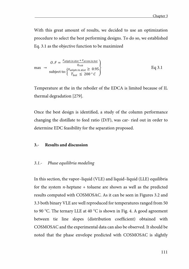
Chapter 3
111
With this great amount of results, we decided to use an optimization
procedure to select the best performing designs. To do so, we established
Eq. 3.1 as the objective function to be maximized
max → 𝑂𝑂.𝐹𝐹 =
𝐹𝐹𝐶𝐶𝐶𝐶𝑖𝑖𝐸𝐸ℎ 𝑖𝑖𝑖𝑖 𝑑𝑑𝑖𝑖𝑑𝑑𝑑𝑑 + 𝐹𝐹𝐶𝐶𝑎𝑎𝑎𝑎𝑚𝑚 𝑖𝑖𝑖𝑖 𝑏𝑏𝑎𝑎𝑑𝑑
𝑄𝑄𝑎𝑎𝑟𝑟𝑏𝑏
subject to: �𝑥𝑥𝑎𝑎𝑎𝑎𝑖𝑖𝑎𝑎ℎ 𝑖𝑖𝑛𝑛 𝑑𝑑𝑖𝑖𝑑𝑑𝑑𝑑 ≥ 0.95𝑇𝑇𝑏𝑏𝑏𝑏𝑑𝑑 ≤ 200 𝐶𝐶
� Eq 3.1
Temperature at the in the reboiler of the EDCA is limited because of IL
thermal degradation [279].
Once the best design is identified, a study of the column performance
changing the distillate to feed ratio (D/F), was car- ried out in order to
determine EDC feasibility for the separation proposed.
3.- Results and discussion
3.1.- Phase equilibria modeling
In this section, the vapor–liquid (VLE) and liquid–liquid (LLE) equilibria
for the system n-heptane + toluene are shown as well as the predicted
results computed with COSMOSAC. As it can be seen in Figures 3.2 and
3.3 both binary VLE are well reproduced for temperatures ranged from 50
to 90 C. The ternary LLE at 40 C is shown in Fig. 4. A good agreement
between tie line slopes (distribution coefficient) obtained with
COSMOSAC and the experimental data can also be observed. It should be
noted that the phase envelope predicted with COSMOSAC is slightly
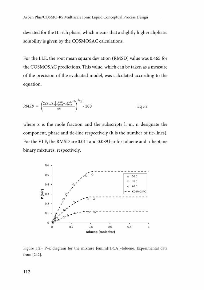
Aspen Plus/COSMO-RS Multiscale Ionic Liquid Conceptual Process Design .
112
deviated for the IL rich phase, which means that a slightly higher aliphatic
solubility is given by the COSMOSAC calculations.
For the LLE, the root mean square deviation (RMSD) value was 0.465 for
the COSMOSAC predictions. This value, which can be taken as a measure
of the precision of the evaluated model, was calculated according to the
equation:
𝑅𝑅𝑅𝑅𝑅𝑅𝑅𝑅 = �∑ ∑ ∑ �𝑥𝑥𝐶𝐶𝑚𝑚𝑖𝑖
𝑟𝑟𝐸𝐸𝐸𝐸−𝑥𝑥𝐶𝐶𝑚𝑚𝑖𝑖𝐶𝐶𝐶𝐶𝐶𝐶𝐶𝐶�
2𝑖𝑖𝑚𝑚𝐶𝐶
6𝑘𝑘�
12�
· 100 Eq 3.2
where x is the mole fraction and the subscripts l, m, n designate the
component, phase and tie-line respectively (k is the number of tie-lines).
For the VLE, the RMSD are 0.011 and 0.089 bar for toluene and n-heptane
binary mixtures, respectively.
Figure 3.2.- P–x diagram for the mixture [emim][DCA]–toluene. Experimental data from [242].
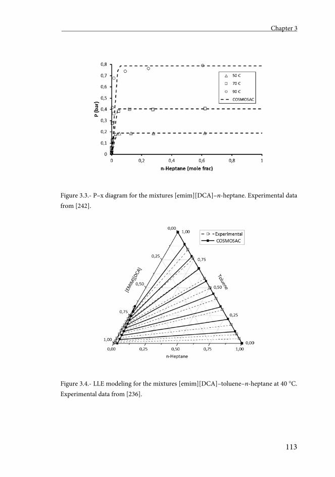
Chapter 3
113
Figure 3.3.- P–x diagram for the mixtures [emim][DCA]–n-heptane. Experimental data from [242].
Figure 3.4.- LLE modeling for the mixtures [emim][DCA]–toluene–n-heptane at 40 C. Experimental data from [236].
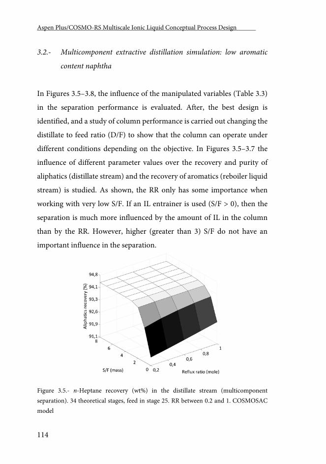
Aspen Plus/COSMO-RS Multiscale Ionic Liquid Conceptual Process Design .
114
3.2.- Multicomponent extractive distillation simulation: low aromatic
content naphtha
In Figures 3.5–3.8, the influence of the manipulated variables (Table 3.3)
in the separation performance is evaluated. After, the best design is
identified, and a study of column performance is carried out changing the
distillate to feed ratio (D/F) to show that the column can operate under
different conditions depending on the objective. In Figures 3.5–3.7 the
influence of different parameter values over the recovery and purity of
aliphatics (distillate stream) and the recovery of aromatics (reboiler liquid
stream) is studied. As shown, the RR only has some importance when
working with very low S/F. If an IL entrainer is used (S/F > 0), then the
separation is much more influenced by the amount of IL in the column
than by the RR. However, higher (greater than 3) S/F do not have an
important influence in the separation.
Figure 3.5.- n-Heptane recovery (wt%) in the distillate stream (multicomponent separation). 34 theoretical stages, feed in stage 25. RR between 0.2 and 1. COSMOSAC model
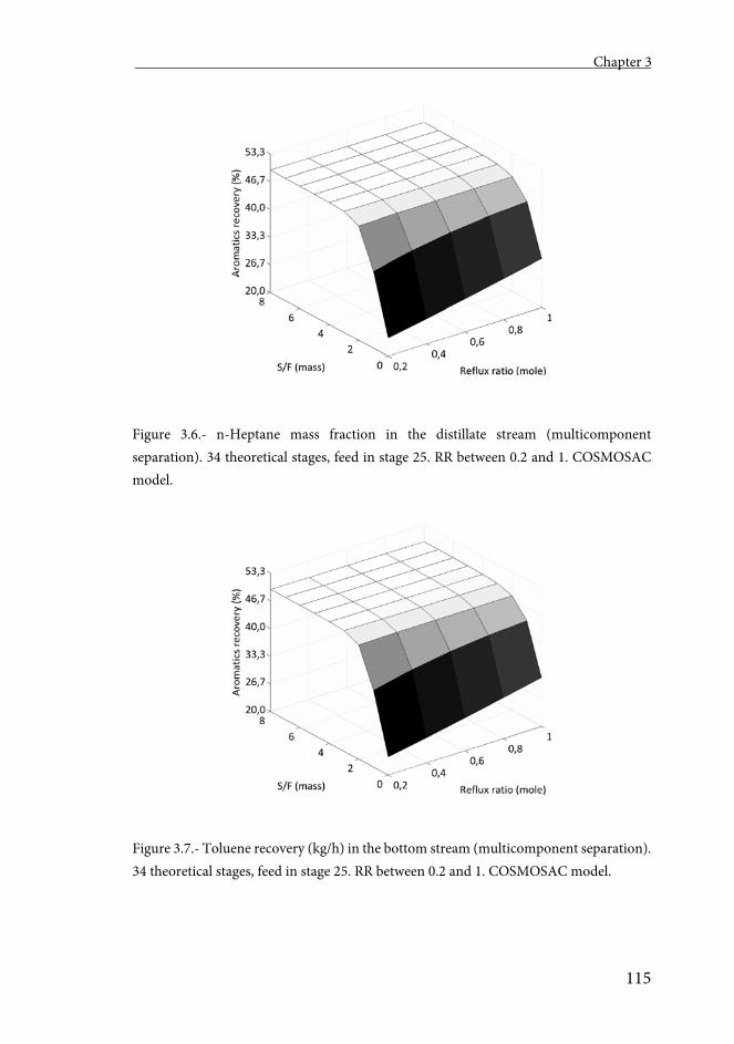
Chapter 3
115
Figure 3.6.- n-Heptane mass fraction in the distillate stream (multicomponent separation). 34 theoretical stages, feed in stage 25. RR between 0.2 and 1. COSMOSAC model.
Figure 3.7.- Toluene recovery (kg/h) in the bottom stream (multicomponent separation). 34 theoretical stages, feed in stage 25. RR between 0.2 and 1. COSMOSAC model.
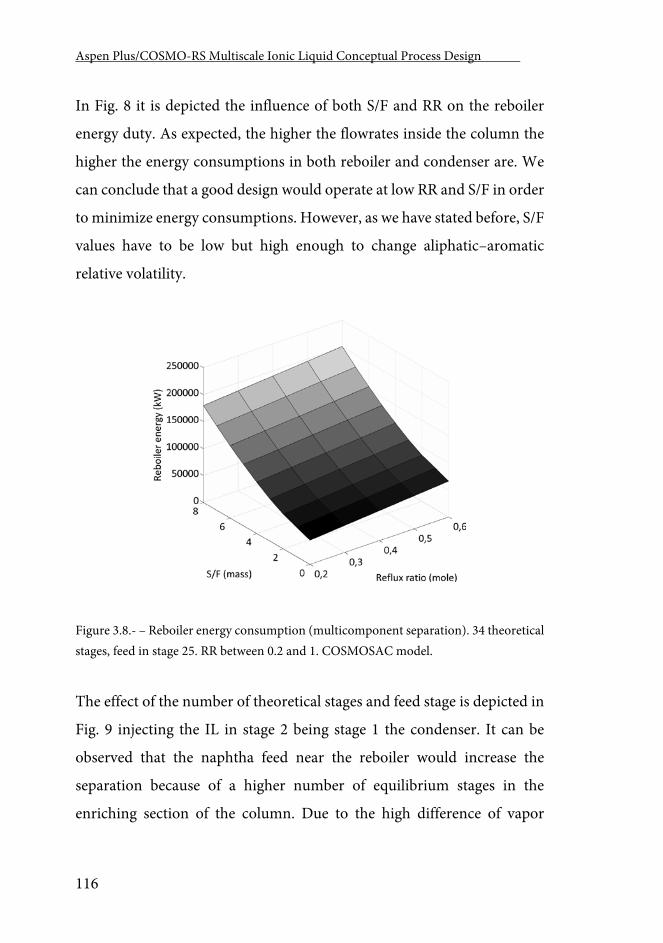
Aspen Plus/COSMO-RS Multiscale Ionic Liquid Conceptual Process Design .
116
In Fig. 8 it is depicted the influence of both S/F and RR on the reboiler
energy duty. As expected, the higher the flowrates inside the column the
higher the energy consumptions in both reboiler and condenser are. We
can conclude that a good design would operate at low RR and S/F in order
to minimize energy consumptions. However, as we have stated before, S/F
values have to be low but high enough to change aliphatic–aromatic
relative volatility.
Figure 3.8.- – Reboiler energy consumption (multicomponent separation). 34 theoretical stages, feed in stage 25. RR between 0.2 and 1. COSMOSAC model.
The effect of the number of theoretical stages and feed stage is depicted in
Fig. 9 injecting the IL in stage 2 being stage 1 the condenser. It can be
observed that the naphtha feed near the reboiler would increase the
separation because of a higher number of equilibrium stages in the
enriching section of the column. Due to the high difference of vapor
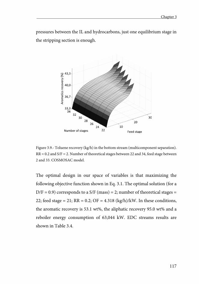
Chapter 3
117
pressures between the IL and hydrocarbons, just one equilibrium stage in
the stripping section is enough.
Figure 3.9.- Toluene recovery (kg/h) in the bottom stream (multicomponent separation). RR = 0.2 and S/F = 2. Number of theoretical stages between 22 and 34, feed stage between 2 and 33. COSMOSAC model.
The optimal design in our space of variables is that maximizing the
following objective function shown in Eq. 3.1. The optimal solution (for a
D/F = 0.9) corresponds to a S/F (mass) = 2; number of theoretical stages =
22; feed stage = 21; RR = 0.2; OF = 4.318 (kg/h)/kW. In these conditions,
the aromatic recovery is 53.1 wt%, the aliphatic recovery 95.0 wt% and a
reboiler energy consumption of 63,044 kW. EDC streams results are
shown in Table 3.4.
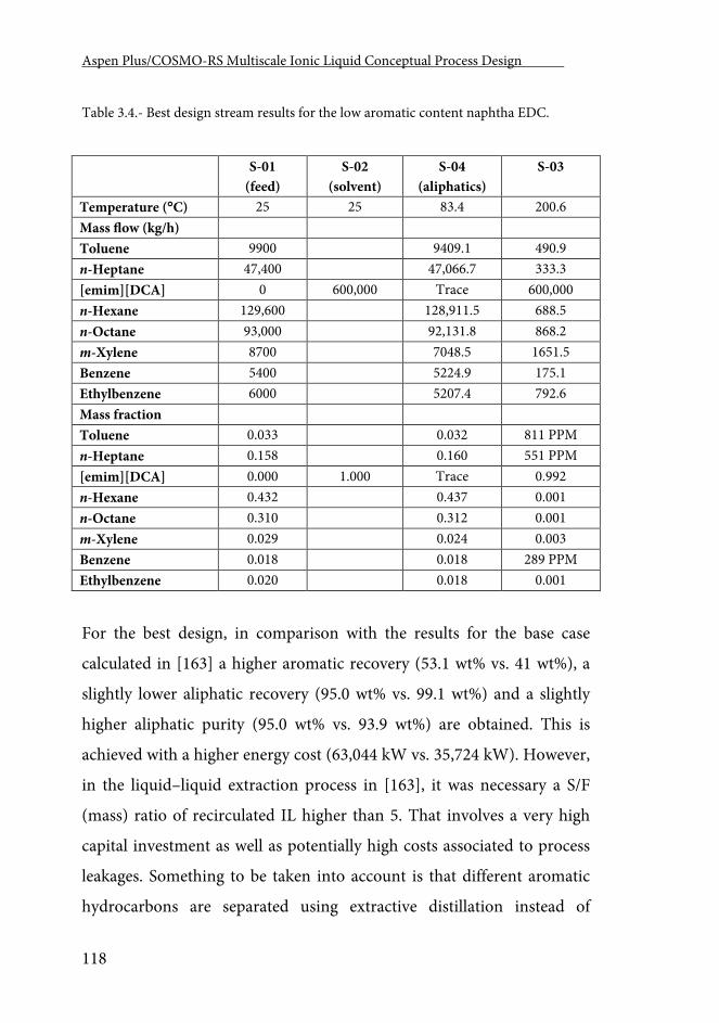
Aspen Plus/COSMO-RS Multiscale Ionic Liquid Conceptual Process Design .
118
Table 3.4.- Best design stream results for the low aromatic content naphtha EDC.
S-01 (feed)
S-02 (solvent)
S-04 (aliphatics)
S-03
Temperature (C) 25 25 83.4 200.6 Mass flow (kg/h) Toluene 9900 9409.1 490.9 n-Heptane 47,400 47,066.7 333.3 [emim][DCA] 0 600,000 Trace 600,000 n-Hexane 129,600 128,911.5 688.5 n-Octane 93,000 92,131.8 868.2 m-Xylene 8700 7048.5 1651.5 Benzene 5400 5224.9 175.1 Ethylbenzene 6000 5207.4 792.6 Mass fraction Toluene 0.033 0.032 811 PPM n-Heptane 0.158 0.160 551 PPM [emim][DCA] 0.000 1.000 Trace 0.992 n-Hexane 0.432 0.437 0.001 n-Octane 0.310 0.312 0.001 m-Xylene 0.029 0.024 0.003 Benzene 0.018 0.018 289 PPM Ethylbenzene 0.020 0.018 0.001
For the best design, in comparison with the results for the base case
calculated in [163] a higher aromatic recovery (53.1 wt% vs. 41 wt%), a
slightly lower aliphatic recovery (95.0 wt% vs. 99.1 wt%) and a slightly
higher aliphatic purity (95.0 wt% vs. 93.9 wt%) are obtained. This is
achieved with a higher energy cost (63,044 kW vs. 35,724 kW). However,
in the liquid–liquid extraction process in [163], it was necessary a S/F
(mass) ratio of recirculated IL higher than 5. That involves a very high
capital investment as well as potentially high costs associated to process
leakages. Something to be taken into account is that different aromatic
hydrocarbons are separated using extractive distillation instead of
Chapter 3
119
conventional LL extraction. In LL extraction mainly C6 and C7 aromatics
are separated while C8s remain in the aliphatic stream. With extractive
distillation C8 aromatics are completely removed being light aromatics the
impurities in the aliphatics stream.
In order to establish the optimum of the system, it would be necessary to
carry out a detailed economic study with specific prices of raw naphtha,
ILs, products and energy which is out of the scope of this work. However,
just considering energy consumption in the reboiler (with a medium
pressure steam price of 2.2 · 10−6 $/kJ) the annual energy consumption
would be of 3.9 M$/year. This value suggests that the expected total energy
cost would be higher than the liquid–liquid extraction based process
proposed by [64] (total energy cost of 5 M$/year).
Once a good design has been identified, an analysis of the influence of
distillate flowrate on the separation performance is carried out for the
optimal design.
EDC operation is here analyzed showing that higher distil- late flowrates
needs of higher energy consumptions and also increases bottom
temperature (Fig. 10). Products qualities and quantities are also affected.
That is, it is possible to operate the EDC to obtain high purity aliphatic
product with low recoveries (operating with low D/F) or it is possible to
operate it to obtain very pure aromatics (operating with high D/F) as seen
in Figures 3.11 and 12.
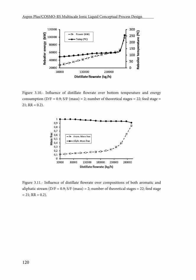
Aspen Plus/COSMO-RS Multiscale Ionic Liquid Conceptual Process Design .
120
Figure 3.10.- Influence of distillate flowrate over bottom temperature and energy consumption (D/F = 0.9; S/F (mass) = 2; number of theoretical stages = 22; feed stage = 21; RR = 0.2).
Figure 3.11.- Influence of distillate flowrate over compositions of both aromatic and aliphatic stream (D/F = 0.9; S/F (mass) = 2; number of theoretical stages = 22; feed stage = 21; RR = 0.2).
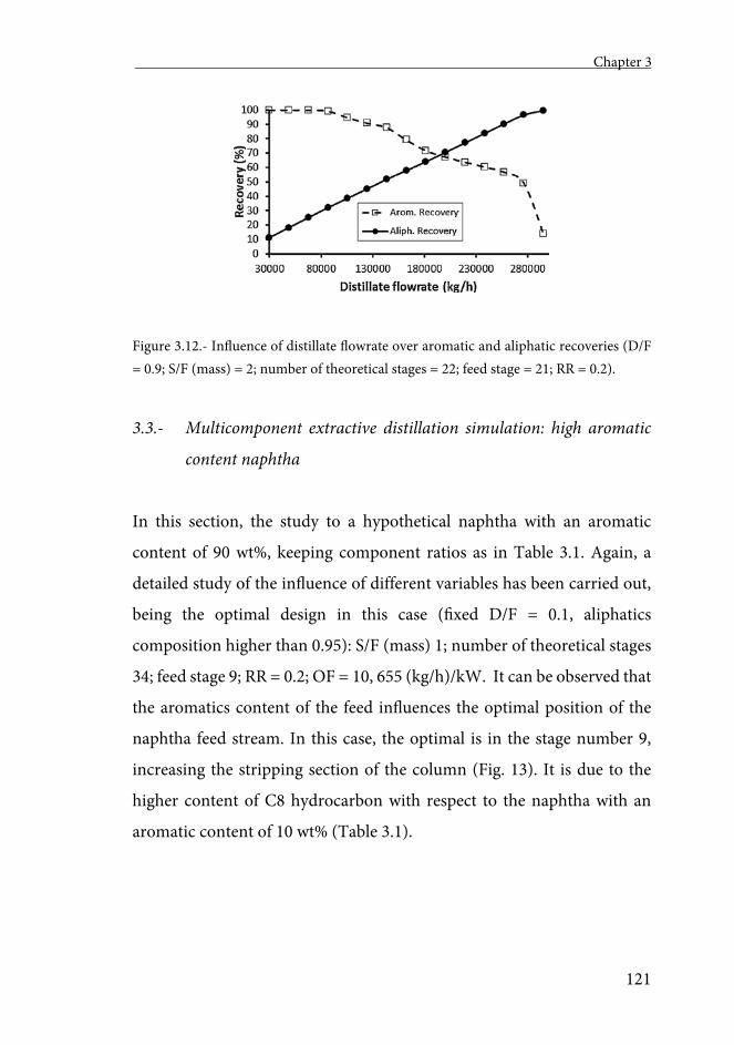
Chapter 3
121
Figure 3.12.- Influence of distillate flowrate over aromatic and aliphatic recoveries (D/F = 0.9; S/F (mass) = 2; number of theoretical stages = 22; feed stage = 21; RR = 0.2).
3.3.- Multicomponent extractive distillation simulation: high aromatic
content naphtha
In this section, the study to a hypothetical naphtha with an aromatic
content of 90 wt%, keeping component ratios as in Table 3.1. Again, a
detailed study of the influence of different variables has been carried out,
being the optimal design in this case (fixed D/F = 0.1, aliphatics
composition higher than 0.95): S/F (mass) 1; number of theoretical stages
34; feed stage 9; RR = 0.2; OF = 10, 655 (kg/h)/kW. It can be observed that
the aromatics content of the feed influences the optimal position of the
naphtha feed stream. In this case, the optimal is in the stage number 9,
increasing the stripping section of the column (Fig. 13). It is due to the
higher content of C8 hydrocarbon with respect to the naphtha with an
aromatic content of 10 wt% (Table 3.1).
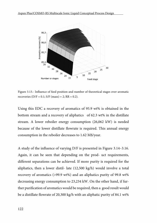
Aspen Plus/COSMO-RS Multiscale Ionic Liquid Conceptual Process Design .
122
Figure 3.13.- Influence of feed position and number of theoretical stages over aromatic recoveries (D/F = 0.1; S/F (mass) = 2; RR = 0.2).
Using this EDC a recovery of aromatics of 95.9 wt% is obtained in the
bottom stream and a recovery of aliphatics of 62.3 wt% in the distillate
stream. A lower reboiler energy consumption (26,062 kW) is needed
because of the lower distillate flowrate is required. This annual energy
consumption in the reboiler decreases to 1.62 M$/year.
A study of the influence of varying D/F is presented in Figure 3.14–3.16.
Again, it can be seen that depending on the prod- uct requirements,
different separations can be achieved. If more purity is required for the
aliphatics, then a lower distil- late (12,500 kg/h) would involve a total
recovery of aromatics (>99.9 wt%) and an aliphatics purity of 99.8 wt%
decreasing energy consumption to 23,234 kW. On the other hand, if fur-
ther purification of aromatics would be required, then a good result would
be a distillate flowrate of 20,300 kg/h with an aliphatic purity of 84.1 wt%
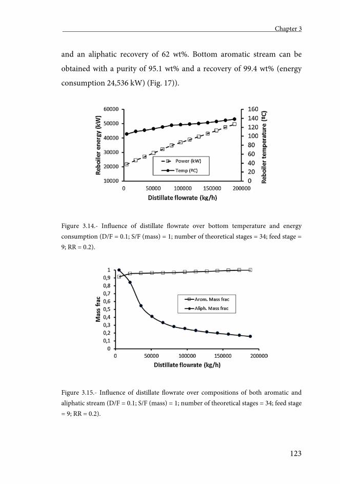
Chapter 3
123
and an aliphatic recovery of 62 wt%. Bottom aromatic stream can be
obtained with a purity of 95.1 wt% and a recovery of 99.4 wt% (energy
consumption 24,536 kW) (Fig. 17)).
Figure 3.14.- Influence of distillate flowrate over bottom temperature and energy consumption (D/F = 0.1; S/F (mass) = 1; number of theoretical stages = 34; feed stage = 9; RR = 0.2).
Figure 3.15.- Influence of distillate flowrate over compositions of both aromatic and aliphatic stream (D/F = 0.1; S/F (mass) = 1; number of theoretical stages = 34; feed stage = 9; RR = 0.2).
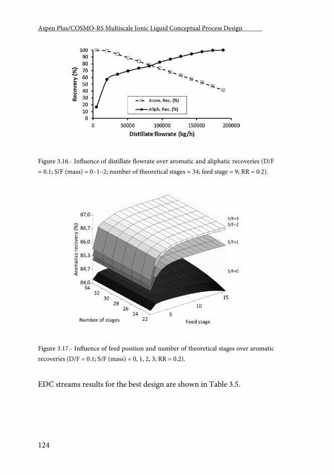
Aspen Plus/COSMO-RS Multiscale Ionic Liquid Conceptual Process Design .
124
Figure 3.16.- Influence of distillate flowrate over aromatic and aliphatic recoveries (D/F = 0.1; S/F (mass) = 0–1–2; number of theoretical stages = 34; feed stage = 9; RR = 0.2).
Figure 3.17.- Influence of feed position and number of theoretical stages over aromatic recoveries (D/F = 0.1; S/F (mass) = 0, 1, 2, 3; RR = 0.2).
EDC streams results for the best design are shown in Table 3.5.
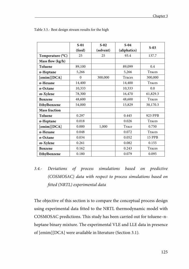
Chapter 3
125
Table 3.5.- Best design stream results for the high
S-01
(feed) S-02
(solvent) S-04
(aliphatics) S-03
Temperature (C) 25 25 93.4 137.7 Mass flow (kg/h) Toluene 89,100 89,099 0.4 n-Heptane 5,266 5,266 Traces [emim][DCA] 0 300,000 Traces 300,000 n-Hexane 14,400 14,400 Traces n-Octane 10,333 10,333 0.0 m-Xylene 78,300 16,470 61,829.3 Benzene 48,600 48,600 Traces Ethylbenzene 54,000 15,829 38,170.3 Mass fraction Toluene 0.297 0.445 923 PPB n-Heptane 0.018 0.026 Traces [emim][DCA] 0.000 1,000 Trace 0.750 n-Hexane 0.048 0.072 Traces n-Octane 0.034 0.052 15 PPB m-Xylene 0.261 0.082 0.155 Benzene 0.162 0.243 Traces Ethylbenzene 0.180 0.079 0.095
3.4.- Deviations of process simulations based on predictive
(COSMOSAC) data with respect to process simulations based on
fitted (NRTL) experimental data
The objective of this section is to compare the conceptual process design
using experimental data fitted to the NRTL thermodynamic model with
COSMOSAC predictions. This study has been carried out for toluene–n-
heptane binary mixture. The experimental VLE and LLE data in presence
of [emim][DCA] were available in literature (Section 3.1).
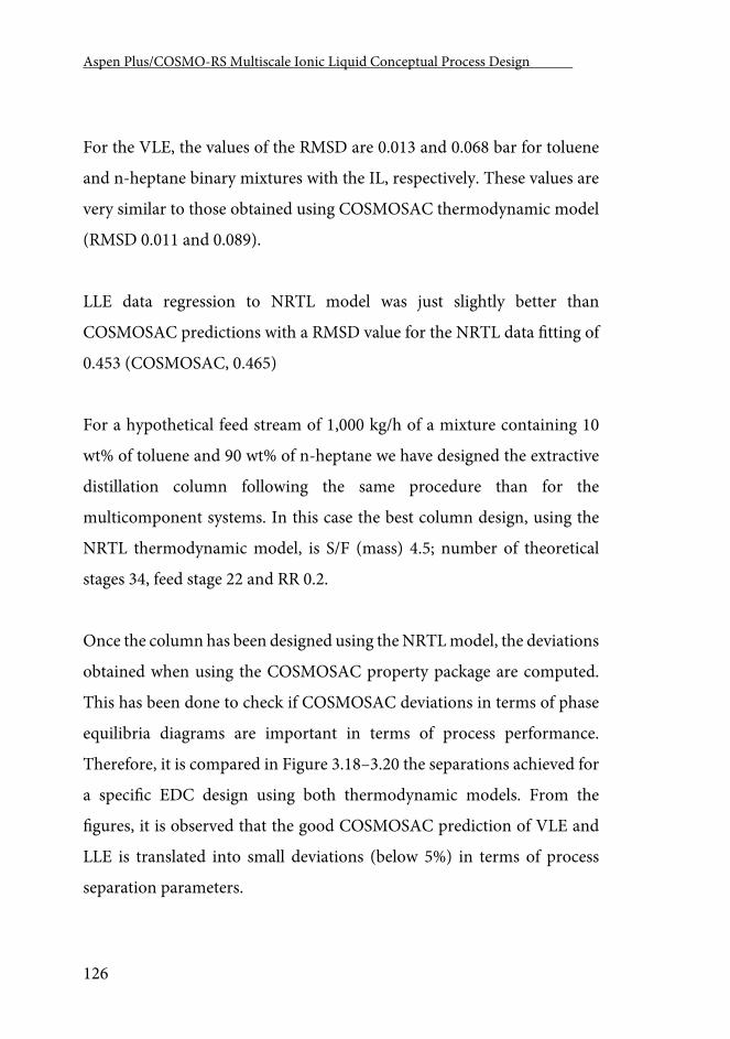
Aspen Plus/COSMO-RS Multiscale Ionic Liquid Conceptual Process Design .
126
For the VLE, the values of the RMSD are 0.013 and 0.068 bar for toluene
and n-heptane binary mixtures with the IL, respectively. These values are
very similar to those obtained using COSMOSAC thermodynamic model
(RMSD 0.011 and 0.089).
LLE data regression to NRTL model was just slightly better than
COSMOSAC predictions with a RMSD value for the NRTL data fitting of
0.453 (COSMOSAC, 0.465)
For a hypothetical feed stream of 1,000 kg/h of a mixture containing 10
wt% of toluene and 90 wt% of n-heptane we have designed the extractive
distillation column following the same procedure than for the
multicomponent systems. In this case the best column design, using the
NRTL thermodynamic model, is S/F (mass) 4.5; number of theoretical
stages 34, feed stage 22 and RR 0.2.
Once the column has been designed using the NRTL model, the deviations
obtained when using the COSMOSAC property package are computed.
This has been done to check if COSMOSAC deviations in terms of phase
equilibria diagrams are important in terms of process performance.
Therefore, it is compared in Figure 3.18–3.20 the separations achieved for
a specific EDC design using both thermodynamic models. From the
figures, it is observed that the good COSMOSAC prediction of VLE and
LLE is translated into small deviations (below 5%) in terms of process
separation parameters.
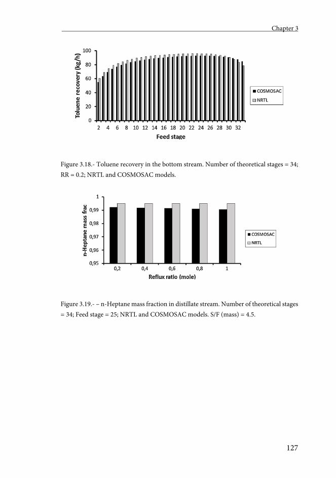
Chapter 3
127
Figure 3.18.- Toluene recovery in the bottom stream. Number of theoretical stages = 34; RR = 0.2; NRTL and COSMOSAC models.
Figure 3.19.- – n-Heptane mass fraction in distillate stream. Number of theoretical stages = 34; Feed stage = 25; NRTL and COSMOSAC models. S/F (mass) = 4.5.
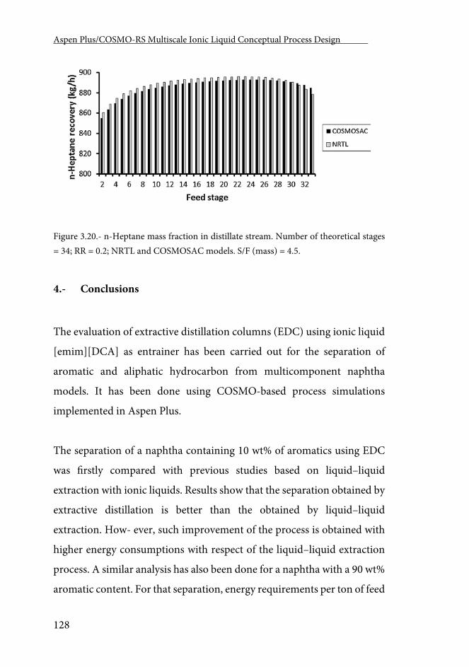
Aspen Plus/COSMO-RS Multiscale Ionic Liquid Conceptual Process Design .
128
Figure 3.20.- n-Heptane mass fraction in distillate stream. Number of theoretical stages = 34; RR = 0.2; NRTL and COSMOSAC models. S/F (mass) = 4.5.
4.- Conclusions
The evaluation of extractive distillation columns (EDC) using ionic liquid
[emim][DCA] as entrainer has been carried out for the separation of
aromatic and aliphatic hydrocarbon from multicomponent naphtha
models. It has been done using COSMO-based process simulations
implemented in Aspen Plus.
The separation of a naphtha containing 10 wt% of aromatics using EDC
was firstly compared with previous studies based on liquid–liquid
extraction with ionic liquids. Results show that the separation obtained by
extractive distillation is better than the obtained by liquid–liquid
extraction. How- ever, such improvement of the process is obtained with
higher energy consumptions with respect of the liquid–liquid extraction
process. A similar analysis has also been done for a naphtha with a 90 wt%
aromatic content. For that separation, energy requirements per ton of feed
Chapter 3
129
are lower than for the case of a naphtha containing 10 wt% of aromatics.
Besides, the goodness of the predictions obtained with the COSMOSAC
thermodynamic model has been analyzed in terms of both fluid phase
equilibria and process separations for a binary aliphatic–aromatic system
with available experimental for its mixture with [emim][DCA]. Results
show a very good agreement between VLE and LLE data predicted by
COSMOSAC and the experimental values. This experimental data was
fitted to the NRTL model and then EDC designs were performed using
both NRTL and COSMOSAC property packages. Very similar EDC
designs were obtained in both cases showing that the good VLE and LLE
COSMOSAC predictions are translated into process simulation results.

Chapter 4 Ionic Liquids for Post-Combustion CO2 Capture by Physical
Absorption. Thermodynamic, Kinetic and Process Analysis

Chapter 4.
133
Chapter 4
Ionic Liquids for post-combustion CO2 capture by physical absorption. Thermodynamic, kinetic and process analysis
Abstract
The post-combustion CO2 physical absorption with ionic liquids (ILs) is
studied in this work using a COSMO-based methodology that allows
including ILs into Aspen Plus. Firstly, the performance of 8 ILs with
different nature in the absorption and regeneration individual operations
is evaluated in commercial packed columns at different temperature and
pressure conditions adding thermodynamic, mass transfer kinetic and
technical criteria to the IL selection. Secondly, both the absorption and
regeneration are integrated in a complete CO2 capture process simulation.
The interdependency of variables and their influence in the total operating
cost (OPEX) is estimated. The total energy needed for this capture process
is compared to homologue results presented in literature for other CO2
capture technologies. Finally, we provide a preliminary estimation of the
capital cost (CAPEX) of the process for a pilot near to industrial scaled
plant.
Aspen Plus/COSMO-RS Multiscale Ionic Liquid Conceptual Process Design .
134
1.- Introduction
For some years to come, petroleum, coal and natural gas will continue to
be the primary global energy source being coal-fired power plants the
largest source of CO2 emission. According to the International Energy
Outlook 2016 Reference Case [280, 281], coal will remain the second-
largest energy source worldwide behind petroleum and other liquids until
2030. World Energy Outlook 2015 [111] projections have emphasized that
coal markets are at a critical point as coal diverges the most across
scenarios, being the future behavior of China demand the key. China,
India and the United States today account for 72% of global coal demand.
Between 2000 and 2009, Chinese coal use grew on average by 9.5% per
year. Coal consumption for the OECD countries peaked in 2007, however,
in 2014, coal-fired power plants still accounted for about one-third of the
energy-related carbon dioxide emissions from the United States [111].
The share of global coal market arising from non-OECD countries is
expected to rise from 66% to 82% in 2035 [282]. According to the
International Energy Agency (IEA), 41% of total electricity is obtained
from coal-fired power plants [111]. In the environment of an overall
growth of coal demand, Carbon Capture and Storage (CCS), will play a
significant role in reducing emissions from these sources [283]. The
typical Flue Gas produced in a coal-fired power plant is at 1 atm and has a
CO2 concentration of less than 15%. The process of transforming this low
pressure, low concentration CO2 into a relatively pure CO2 stream is
referred to as post-combustion CO2 capture [284]. This capture
technology is currently considered the most feasible measure to retrofit
Chapter 4.
135
existing power plants, due to its limited impact on the power station
operation itself [283].
There are two different main CO2 capture approaches with different
nature, gas-liquid absorption and gas-solid adsorption. The CO2 capture
by absorption is being studied using amine solvents, amino acid salts,
carbonate systems, aqueous ammonia, immiscible liquids and ionic
liquids [283] as absorbents. The most commonly used solvents for
chemical absorption of CO2 are aqueous amines. The capture process with
amines is an effective technology although solvent loss due to their high
volatility, their reactivity and the energy intensive nature of the
regeneration process, motivates alternative approaches. The measured
and projected reboiler heat duty of the amine scrubbing has been
calculated to be 4.2 GJ/ton of CO2 captured which represents a
thermodynamic efficiency of about 40% [285], estimated using Aspen
Plus. Also, undesired effects appear at the operating conditions, such as
corrosion [286, 287] and solvent degradation [288]. These aspects
diminish the performance of amine-based CO2 capture plants.
Ionic Liquids (ILs) are being evaluated as possible alternatives for the CO2
capture both by physical and chemical absorption due to their a priori
favorable solvent properties: extremely low volatility, tunable solvation
capacity and high thermal stability. Physical absorption may have some
advantages considering the easy IL regeneration by pressure or
temperature swing of the high-pressure CO2 + IL mixture. A large number
of studies have shown that CO2 is very soluble in imidazolium-based ILs
[202, 289-292] as in other IL families [293]. Selecting an IL with optimized
Aspen Plus/COSMO-RS Multiscale Ionic Liquid Conceptual Process Design .
136
properties for a certain application can be a difficult task if we take into
account that a huge number of ILs (estimated to be around 106) [3] with
different thermodynamic and transport properties may be created by
permutation of the cation and anion. In most cases, measured or
calculated gas-liquid thermodynamic data was used in order to select the
IL with appropriate solvation properties for the CO2 separation [291, 294-
303]. Additionally, an important mass transfer kinetic control may occur
in the absorption process [114, 115], especially considering that ILs are, in
most cases, viscous [77]. Therefore, it may be important to include mass
transfer kinetic criteria in the IL selection. Moreover, the IL viscosity range
is so wide (from 4 cP to over 20,000 cP) that some ILs with relatively
similar thermodynamic behavior may perform differently when realistic
operating conditions are considered. In fact, it has been demonstrated that
thermodynamics and kinetics of CO2 physical absorption in ILs do not
always follow the same trends [146]. The mass transfer kinetic behavior
may have a great impact in the column design, energy consumption and
the operational conditions of the CO2 capture process [304]. The viability
evaluation of processes able to perform the CO2 separation by gas-liquid
absorption must, therefore, include thermodynamic, kinetic, operational
and economic criteria.
There have been some efforts towards the description of different solvent-
based post-combustion CO2 capture processes using diverse theoretical
and process simulations. Several studies analyzed the chemical absorption
of CO2 by aqueous ammonia [305-314], amine-based systems [126, 315-
321]; some studies analyzed the chemical absorption of CO2 using ILs
[126, 322-325]; and a recent work studied the physical CO2 capture using
Chapter 4.
137
ILs [326] as absorbents. Yu et al. [314] performed a very detailed analysis
of the energy penalty of an aqueous ammonia process for post-
combustion CO2 capture, simulating the entire process, including the CO2
absorption, CO2 desorption, CO2 compression, NH3 abatement and NH3
recovery process, taking into account the mass transfer control in the
calculation through a Rate-based simulation. The minimum energy
requirement was identified as 4.07 GJ/ton of recovered CO2, being the
solvent regeneration responsible of, approximately, 70% of this energy.
Regarding the process analysis of CO2 capture based on absorption with
ILs, Shiflett et al [126] presented process simulations for both an amine-
based system (using monoethanolamine [MEA] as CO2 absorbent) and an
IL (1-butyl-3-methylimidazolium Acetate, [bmim][Ac]) that chemically
absorbs CO2. The authors considered the thermodynamic behavior of
both processes showing that, potentially, the use of ILs able to chemically
absorb CO2 may reduce the energy losses by 16%. The total energy needs
reported were around 3.2 GJ/ton of CO2 absorbed, with an 11% lower
capital investment. Zhai and Rubin [324], studied an aprotic heterocyclic
anion (AHA)-based IL (trihexyl-(tetradecyl)phosphonium 2-
cyanopyrrolide [P6,6,6,14][2-CNpyr]), recently developed at the University
of Notre Dame [327]. The calculated steam energy used for the solvent
regeneration reached 3.6 GJ/ton. Their preliminary results showed that for
90% CO2 capture, the estimated capture cost ($62.4/ton of captured CO2)
would be higher than the U.S. Department of Energy’s target of $40 per
metric ton. Xie et al [326] made a very complete thermodynamic study of
the physical absorption of CO2 using ILs. Firstly, they performed
consistency tests and discarded unreliable CO2 solubility data. To
Aspen Plus/COSMO-RS Multiscale Ionic Liquid Conceptual Process Design .
138
represent the gas solubility, the non-random two liquid (NRTL) Redlich-
Kwong (RK) model was successfully used in Aspen Plus simulations.
Further, they investigated the enthalpy of absorption taking into account
the CO2 dissolution enthalpy and the excess enthalpy contributions. They
stated that the absorption enthalpy decreases with increasing the alkyl
chain length of the cation and strongly depends on the anion. They also
studied the IL regeneration by pressure and temperature swing.
Regenerating the IL at constant temperature (298 K) by pressure swing
had an energy demand of 0.2 GJ/ton of CO2 when using the 1-ethyl-3-
methylimdazolium ethylsulfate [emim][EtSO4] IL, while recovering the IL
by temperature swing at constant pressure had an energy penalty of 20.2
GJ/ton of CO2 when using 1-ethyl-3-methylimdazolium
hexafluorophosphate [emim][PF6]. Combining both methods had an
energy demand of only 1.3 GJ/ton of CO2 for 1-butyl-3-
methylimdazolium bis(trifluoromethylsulfonyl)imide [bmim][NTf2] IL as
best physical absorbent.
In the present work, we evaluated the role of CO2 mass transfer kinetics in
the physical absorption operation and the influence of the IL nature in the
IL regeneration as new criteria for the ILs selection in the post-combustion
CO2 capture process. After, we simulated the entire CO2 capture process
optimizing the economic impact of the operating conditions into the total
operating costs (OPEX); obtaining valuable information about the energy
consumption of the CO2 capture technology via physical absorption with
ILs. Finally, we provided a preliminary estimation of the capital cost
(CAPEX) of a near to industrial scaled post-combustion CO2 capture
plant. For this purpose, an a priori multiscale strategy developed in our
Chapter 4.
139
group for the study of new industrial processes was applied [215].
COnductor-like Screening MOdel for Real Solvent (COSMO-RS) [192]
calculations were used in the Aspen Plus commercial process simulator
both to create the non-databank components -the ILs in this case- and to
specify the COSMOSAC (COSMO-Segment Activity Coefficient) [212].
Previous works [56, 80, 81, 153, 162, 163, 165, 215] demonstrated that this
computational approach guarantees the accuracy level required in the
Conceptual and first stages of the Basic Engineering. This a priori
multiscale methodology has been successfully applied to the study of
toluene absorption with ILs [162], the regeneration of ILs by vacuum
distillation [153], absorption refrigeration cycles using ILs as absorbents
[56], the separation of aromatic-aliphatic hydrocarbon multicomponent
mixtures using ILs as extracting solvents [80, 81, 163] and for the CO2
capture by physical absorption from biogas streams [165]. The results of
this later study, demonstrated that the applied methodology can predict
plant efficiencies and production costs of large scale CO2 capture processes
using ILs without needing the gas solubility experimental data. In the
current analysis, the treatment of a multicomponent post-combustion
inlet Flue Gas by physical absorption with ILs was modeled. We evaluated
8 imidazolium based ILs with different anions previously proposed as
promising CO2 physical absorbents (bis(trifluoromethylsulfonyl)imide
[NTf2], trifluoromethanesulfonate [TfO], hexafluorophosphate [PF6],
tris(pentafluoroethyl)trifluorophosphate [FEP]) [294] (Table A_5). The
predictive capability of the methodology for this process was evaluated by
comparing the estimated and experimental values of thermodynamic (IL-
CO2 vapor liquid equilibria and density) and mass transfer kinetic
(viscosity, surface tension and CO2 diffusivity) properties.
Aspen Plus/COSMO-RS Multiscale Ionic Liquid Conceptual Process Design .
140
The process most commonly proposed for the physical absorption of CO2
consists of two sections, the physical absorption unit itself and the IL
regeneration by temperature and/or pressure swing. Aspen Plus process
simulations of both sections were performed to select the most suitable IL.
The absorber was modeled using the RADFRAC Aspen Plus model. The
RADFRAC model makes it possible to evaluate the absorption both in
Equilibrium (without mass transfer kinetics) and in Rate-based (mass
transfer kinetic control taken into account) modes of operation. This
analysis, allows the inclusion of realistic information (with detailed system
behavior of commercial packed columns) into the IL selection criteria set.
The regeneration, on the other hand, was modeled using the single stage,
two phase separation column implemented in Aspen Plus with the name
of FLASH2 since one stage was enough to regenerate completely the IL.
After selecting the most suitable IL with the information provided by the
simulation of the absorption and regeneration individual operations, the
complete process (both units interconnected) was simulated taking into
consideration the interdependency between the operating conditions of
both sections and their relevance into the total operating costs (OPEX). In
this sense, we studied the economic impact that the absorption and
regeneration pressure, and the regenerated IL purity may have in the
global CO2 capture process OPEX. We considered for this analysis the
OPEX results of the sum of the electrical cost of the compressors and
pumps, the refrigeration water and the high-pressure steam needed in
order to maintain the thermal and pressure conditions of the system. This
analysis, carried out with the absorption column in Rate-based mode (i.e.
mass transfer and vendor information about the packed column taken
Chapter 4.
141
into account), provided us with valuable information about the optimized
energy needs of this process, making it possible to compare this
technology with other processes analyzed in literature. Finally, a
preliminary estimation of the capital cost (CAPEX) of a near to industrial
scaled pilot plant was carried out.
2.- Computational Section
2.1.- Conceptual Process Design
Figure 4.1 presents the simplified CO2 physical absorption process using
ionic liquids as absorbents. A more complete representation of the
simulated process is shown in Figures A_3 and A_4 of the Appendices.
The desulphurized Flue Gas (S-01) exiting the power plant is compressed
and cooled (Figure A_3) before entering the absorption section (Figure
A_4). During this pre-compression and cooling process, part of the water
present originally in the Flue Gas (S-02) is removed. After, the
desulphurized and dehydrated Flue Gas (S-03), is fed to the main
absorption tower (T-100) where the gas contacts with the IL (S-05) and
where the CO2 is absorbed. The clean gas (S-07) exits the overhead of T-
100. The absorbed CO2 and the IL are heated in E-101 and E-103 and
decompressed in V-100 to regenerate the IL (S-13) and separate the pure
CO2 (S-14) in the single stage separation column (T-101). The regenerated
IL (S-13), is then compressed (P-100) and cooled (E-101 and E-102), and
recycled back (S-05) to the absorber (T-100).
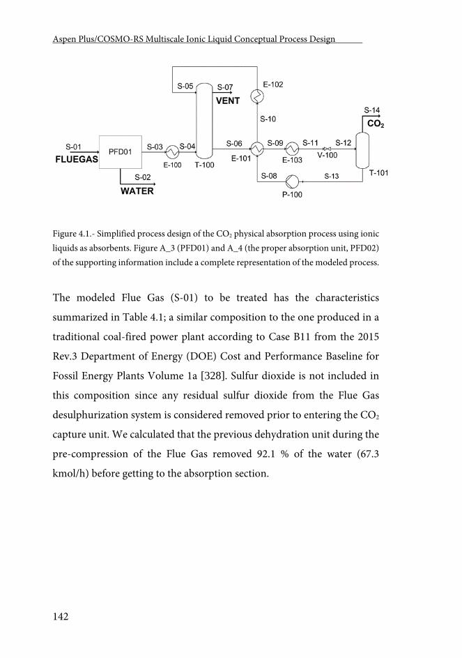
Aspen Plus/COSMO-RS Multiscale Ionic Liquid Conceptual Process Design .
142
Figure 4.1.- Simplified process design of the CO2 physical absorption process using ionic liquids as absorbents. Figure A_3 (PFD01) and A_4 (the proper absorption unit, PFD02) of the supporting information include a complete representation of the modeled process.
The modeled Flue Gas (S-01) to be treated has the characteristics
summarized in Table 4.1; a similar composition to the one produced in a
traditional coal-fired power plant according to Case B11 from the 2015
Rev.3 Department of Energy (DOE) Cost and Performance Baseline for
Fossil Energy Plants Volume 1a [328]. Sulfur dioxide is not included in
this composition since any residual sulfur dioxide from the Flue Gas
desulphurization system is considered removed prior to entering the CO2
capture unit. We calculated that the previous dehydration unit during the
pre-compression of the Flue Gas removed 92.1 % of the water (67.3
kmol/h) before getting to the absorption section.
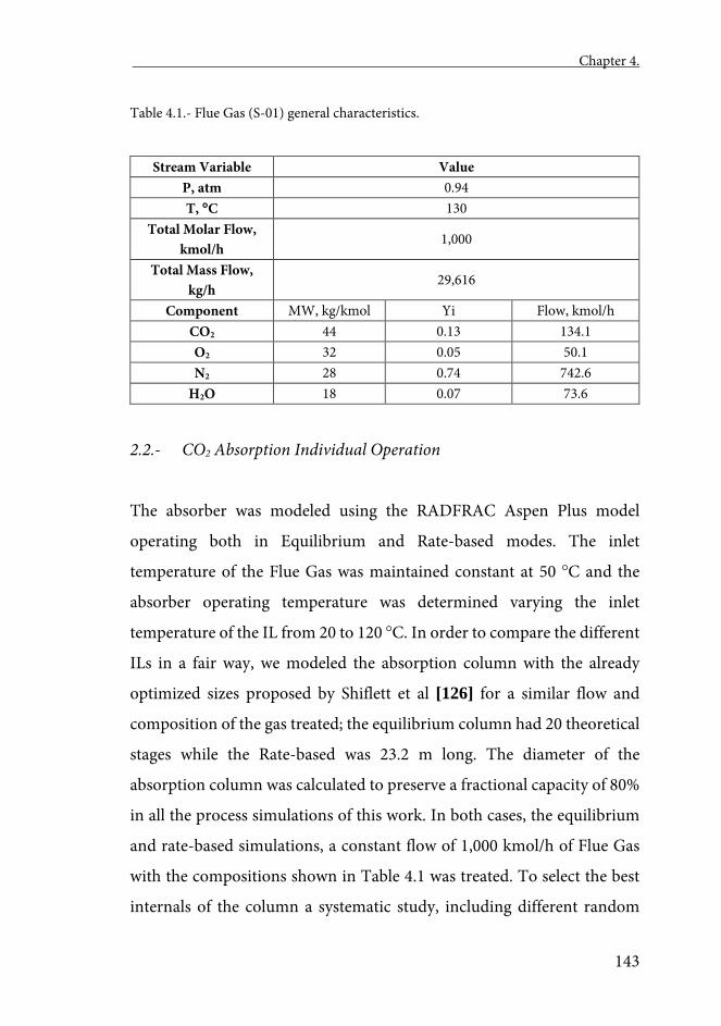
Chapter 4.
143
Table 4.1.- Flue Gas (S-01) general characteristics.
Stream Variable Value P, atm 0.94 T, C 130
Total Molar Flow, kmol/h
1,000
Total Mass Flow, kg/h
29,616
Component MW, kg/kmol Yi Flow, kmol/h CO2 44 0.13 134.1 O2 32 0.05 50.1 N2 28 0.74 742.6
H2O 18 0.07 73.6
2.2.- CO2 Absorption Individual Operation
The absorber was modeled using the RADFRAC Aspen Plus model
operating both in Equilibrium and Rate-based modes. The inlet
temperature of the Flue Gas was maintained constant at 50 C and the
absorber operating temperature was determined varying the inlet
temperature of the IL from 20 to 120 C. In order to compare the different
ILs in a fair way, we modeled the absorption column with the already
optimized sizes proposed by Shiflett et al [126] for a similar flow and
composition of the gas treated; the equilibrium column had 20 theoretical
stages while the Rate-based was 23.2 m long. The diameter of the
absorption column was calculated to preserve a fractional capacity of 80%
in all the process simulations of this work. In both cases, the equilibrium
and rate-based simulations, a constant flow of 1,000 kmol/h of Flue Gas
with the compositions shown in Table 4.1 was treated. To select the best
internals of the column a systematic study, including different random
Aspen Plus/COSMO-RS Multiscale Ionic Liquid Conceptual Process Design .
144
packings was performed. From the results of this study, shown in Figure
A_4 of the Sporting Information, the Flexiring random packing was
selected as it needed lower L/G molar ratios maintaining low pressure
drops.
After selecting the size and internals of the column, the temperature
influence in the CO2 uptake was analyzed both in Equilibrium and Rate-
based modes at a constant pressure of 2 MPa. In this study, 1,000 kmol/h
of IL were used to absorb the CO2. Once both isobaric models were
compared, the operating pressure was studied from 1 to 10 MPa for all the
ILs. In this later analysis, carried out only in Rate-based mode of
operation, the IL temperature was varied in order to obtain a maximum
CO2 uptake. After, the IL amount needed was adjusted so that a 90% CO2
recovery is achieved in the absorber.
2.3.- IL Regeneration Individual Operation
The regeneration column was modeled with the FLASH2 separator as
implemented in Aspen Plus. One theoretical stage was enough to separate
the absorbed CO2 from the ILs. The CO2+IL inlet coming to the
regenerator was, firstly, considered constant. 1,000 kmol/h of a mixture
containing 90 mole% of the IL and 10 mole% of CO2 at 5 MPa and 50 C
were fed to the regeneration column where it is decompressed
immediately separating the CO2 through its overhead. As in Xie et al.
[326], we studied the regeneration process both by pressure and/or
temperature swing. In this analysis, we specified a constant purity of the
Chapter 4.
145
regenerated IL of a 99 mole%, then, we calculated the needed regeneration
temperature at swing pressures between 1 and 10 atmospheres. With the
regeneration results, combined with the previous absorption calculations,
we selected the best IL among the studied ones for the post-combustion
CO2 capture process with ILs by physical absorption.
2.4.- Complete Process
After studying both the absorption and regeneration individual operations
and selecting the best IL, a sensitivity analysis studying the
interdependence of different variables in the model, when the complete
CO2 capture process is simulated, was carried out and related to the
operating costs. 1,000 kmol/h of Flue Gas were treated in a continuous
operating process with a 90% utilization factor (7,884 h/year). A packed
(using Flexiring 0.625 inch internals), 23.2 m tall column was evaluated in
every scenario while its diameter was calculated in order to maintain a
maximum 80% fractional capacity in the column. For the energy
integration of both the absorption and regeneration units, we used the
Pinch methodology with ΔT= 5 C. The absorber was studied at pressures
between 1 and 5 MPa and the regenerator at decompression pressures
between 1 and 10 atmospheres. We also studied the economic effect of the
lean solvent purity in the operating costs. IL concentrations from 98.1 to
99.9 mole% were evaluated. Preliminary equilibrium-based calculations
demonstrated that CO2 stripping occurs at the top of the column at solvent
purities lower than 98.1 mole%.
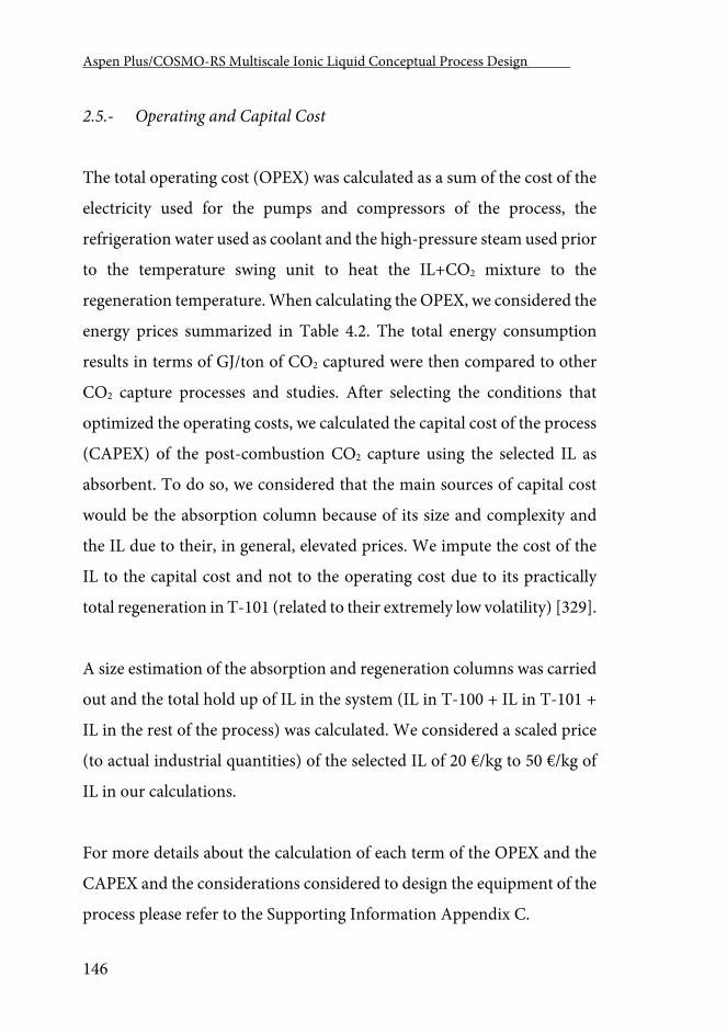
Aspen Plus/COSMO-RS Multiscale Ionic Liquid Conceptual Process Design .
146
2.5.- Operating and Capital Cost
The total operating cost (OPEX) was calculated as a sum of the cost of the
electricity used for the pumps and compressors of the process, the
refrigeration water used as coolant and the high-pressure steam used prior
to the temperature swing unit to heat the IL+CO2 mixture to the
regeneration temperature. When calculating the OPEX, we considered the
energy prices summarized in Table 4.2. The total energy consumption
results in terms of GJ/ton of CO2 captured were then compared to other
CO2 capture processes and studies. After selecting the conditions that
optimized the operating costs, we calculated the capital cost of the process
(CAPEX) of the post-combustion CO2 capture using the selected IL as
absorbent. To do so, we considered that the main sources of capital cost
would be the absorption column because of its size and complexity and
the IL due to their, in general, elevated prices. We impute the cost of the
IL to the capital cost and not to the operating cost due to its practically
total regeneration in T-101 (related to their extremely low volatility) [329].
A size estimation of the absorption and regeneration columns was carried
out and the total hold up of IL in the system (IL in T-100 + IL in T-101 +
IL in the rest of the process) was calculated. We considered a scaled price
(to actual industrial quantities) of the selected IL of 20 €/kg to 50 €/kg of
IL in our calculations.
For more details about the calculation of each term of the OPEX and the
CAPEX and the considerations considered to design the equipment of the
process please refer to the Supporting Information Appendix C.
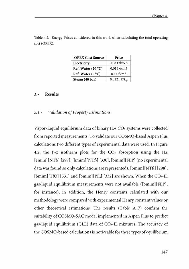
Chapter 4.
147
Table 4.2.- Energy Prices considered in this work when calculating the total operating cost (OPEX).
OPEX Cost Source Price Electricity 0.08 €/kWh Ref. Water (20 C) 0.013 €/m3 Ref. Water (5 C) 0.14 €/m3 Steam (40 bar) 0.0121 €/kg
3.- Results
3.1.- Validation of Property Estimations
Vapor-Liquid equilibrium data of binary IL+ CO2 systems were collected
from reported measurements. To validate our COSMO-based Aspen Plus
calculations two different types of experimental data were used. In Figure
4.2, the P-x isotherm plots for the CO2 absorption using the ILs
[emim][NTf2] [297], [hmim][NTf2] [330], [bmim][FEP] (no experimental
data was found so only calculations are represented), [bmim][NTf2] [298],
[bmim][TfO] [331] and [bmim][PF6] [332] are shown. When the CO2-IL
gas-liquid equilibrium measurements were not available ([bmim][FEP],
for instance), in addition, the Henry constants calculated with our
methodology were compared with experimental Henry constant values or
other theoretical estimations. The results (Table A_7) confirm the
suitability of COSMO-SAC model implemented in Aspen Plus to predict
gas-liquid equilibrium (GLE) data of CO2-IL mixtures. The accuracy of
the COSMO-based calculations is noticeable for these types of equilibrium
Aspen Plus/COSMO-RS Multiscale Ionic Liquid Conceptual Process Design .
148
in these pressure ranges, mean average deviation being only 16.5% when
the P-x diagrams were evaluated and 13% for the Henry constants. These
error values are within the expected range in this step of the process design
(the Conceptual Engineering). According to the reported GLE data, the
CO2 solubility in ILs depends both on the cation and anion selection.
Increasing the alkyl chain length of the cation improves CO2 molar
solubility, while, among the anions studied, the CO2 solubility decreases
as follows: [FEP]> [NTf2]> [TfO]> [PF6] The results obtained via
COSMO-based process simulations in equilibrium mode followed the
same trend of cation and anion effects.
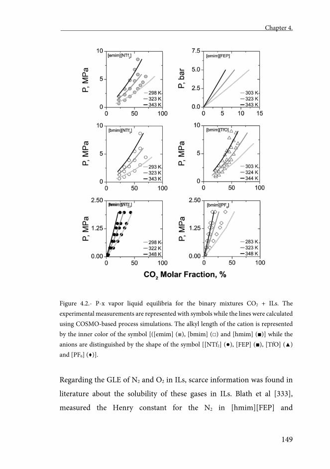
Chapter 4.
149
Figure 4.2.- P-x vapor liquid equilibria for the binary mixtures CO2 + ILs. The experimental measurements are represented with symbols while the lines were calculated using COSMO-based process simulations. The alkyl length of the cation is represented by the inner color of the symbol [([emim] (■), [bmim] (□) and [hmim] (■)] while the anions are distinguished by the shape of the symbol [[NTf2] (●), [FEP] (■), [TfO] (▲) and [PF6] (♦)].
Regarding the GLE of N2 and O2 in ILs, scarce information was found in
literature about the solubility of these gases in ILs. Blath et al [333],
measured the Henry constant for the N2 in [hmim][FEP] and
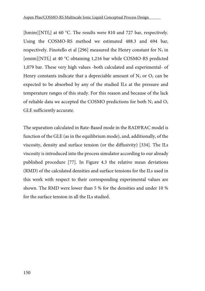
Aspen Plus/COSMO-RS Multiscale Ionic Liquid Conceptual Process Design .
150
[hmim][NTf2] at 60 C. The results were 810 and 727 bar, respectively.
Using the COSMO-RS method we estimated 488.3 and 694 bar,
respectively. Finotello et al [296] measured the Henry constant for N2 in
[emim][NTf2] at 40 C obtaining 1,216 bar while COSMO-RS predicted
1,079 bar. These very high values -both calculated and experimental- of
Henry constants indicate that a depreciable amount of N2 or O2 can be
expected to be absorbed by any of the studied ILs at the pressure and
temperature ranges of this study. For this reason and because of the lack
of reliable data we accepted the COSMO predictions for both N2 and O2
GLE sufficiently accurate.
The separation calculated in Rate-Based mode in the RADFRAC model is
function of the GLE (as in the equilibrium mode), and, additionally, of the
viscosity, density and surface tension (or the diffusivity) [334]. The ILs
viscosity is introduced into the process simulator according to our already
published procedure [77]. In Figure 4.3 the relative mean deviations
(RMD) of the calculated densities and surface tensions for the ILs used in
this work with respect to their corresponding experimental values are
shown. The RMD were lower than 5 % for the densities and under 10 %
for the surface tension in all the ILs studied.
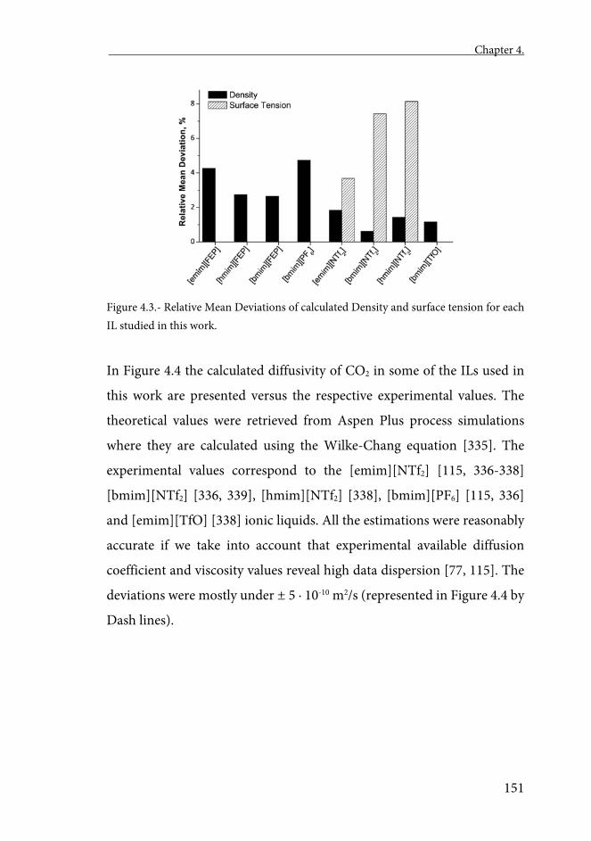
Chapter 4.
151
Figure 4.3.- Relative Mean Deviations of calculated Density and surface tension for each IL studied in this work.
In Figure 4.4 the calculated diffusivity of CO2 in some of the ILs used in
this work are presented versus the respective experimental values. The
theoretical values were retrieved from Aspen Plus process simulations
where they are calculated using the Wilke-Chang equation [335]. The
experimental values correspond to the [emim][NTf2] [115, 336-338]
[bmim][NTf2] [336, 339], [hmim][NTf2] [338], [bmim][PF6] [115, 336]
and [emim][TfO] [338] ionic liquids. All the estimations were reasonably
accurate if we take into account that experimental available diffusion
coefficient and viscosity values reveal high data dispersion [77, 115]. The
deviations were mostly under ± 5 · 10-10 m2/s (represented in Figure 4.4 by
Dash lines).
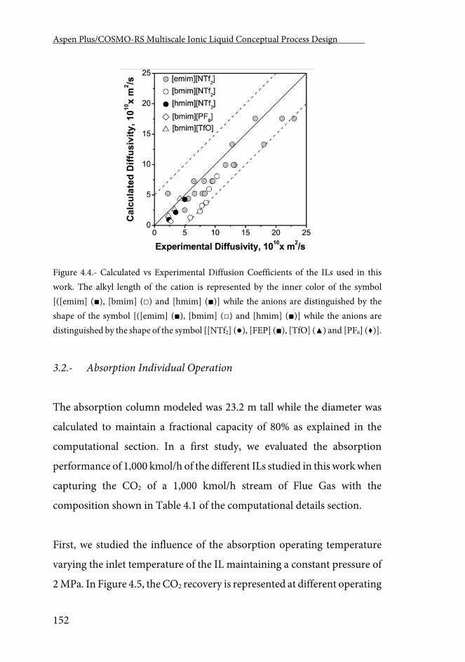
Aspen Plus/COSMO-RS Multiscale Ionic Liquid Conceptual Process Design .
152
Figure 4.4.- Calculated vs Experimental Diffusion Coefficients of the ILs used in this work. The alkyl length of the cation is represented by the inner color of the symbol [([emim] (■), [bmim] (□) and [hmim] (■)] while the anions are distinguished by the shape of the symbol [([emim] (■), [bmim] (□) and [hmim] (■)] while the anions are distinguished by the shape of the symbol [[NTf2] (●), [FEP] (■), [TfO] (▲) and [PF6] (♦)].
3.2.- Absorption Individual Operation
The absorption column modeled was 23.2 m tall while the diameter was
calculated to maintain a fractional capacity of 80% as explained in the
computational section. In a first study, we evaluated the absorption
performance of 1,000 kmol/h of the different ILs studied in this work when
capturing the CO2 of a 1,000 kmol/h stream of Flue Gas with the
composition shown in Table 4.1 of the computational details section.
First, we studied the influence of the absorption operating temperature
varying the inlet temperature of the IL maintaining a constant pressure of
2 MPa. In Figure 4.5, the CO2 recovery is represented at different operating
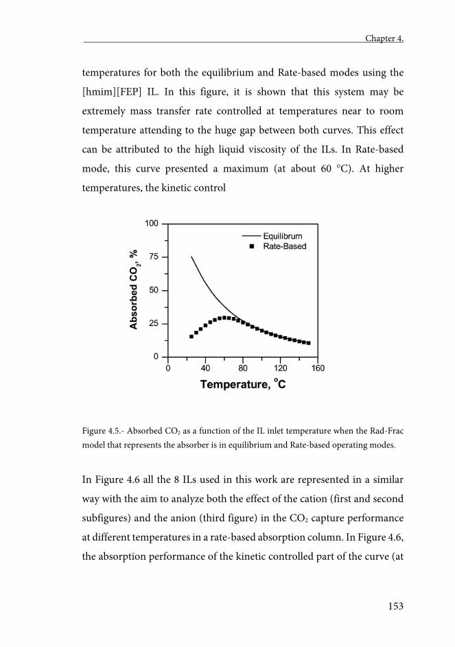
Chapter 4.
153
temperatures for both the equilibrium and Rate-based modes using the
[hmim][FEP] IL. In this figure, it is shown that this system may be
extremely mass transfer rate controlled at temperatures near to room
temperature attending to the huge gap between both curves. This effect
can be attributed to the high liquid viscosity of the ILs. In Rate-based
mode, this curve presented a maximum (at about 60 C). At higher
temperatures, the kinetic control
Figure 4.5.- Absorbed CO2 as a function of the IL inlet temperature when the Rad-Frac model that represents the absorber is in equilibrium and Rate-based operating modes.
In Figure 4.6 all the 8 ILs used in this work are represented in a similar
way with the aim to analyze both the effect of the cation (first and second
subfigures) and the anion (third figure) in the CO2 capture performance
at different temperatures in a rate-based absorption column. In Figure 4.6,
the absorption performance of the kinetic controlled part of the curve (at
Aspen Plus/COSMO-RS Multiscale Ionic Liquid Conceptual Process Design .
154
low temperatures) follows the trend [emim] > [bmim] > [hmim], while, in
the equilibrium controlled zone of the curves (at higher temperatures) the
trend is the opposite. The inversion of the trend when using more real-
alike Rate-based simulations reveal the importance kinetics may have in
the solvent selection, especially when solvents of relatively high viscosity
are involved. Also in Figure 4.6, it can be observed that the anion
performance follows the trend FEP > NTf2 > TfO > PF6. This trend is the
same as the one followed by the experimental data and the equilibrium
calculations in this case, because the viscosity of ILs also follows the trend
FEP < NTf2 < TfO < PF6. This phenomenon continues to occur when
varying the column pressure, decreasing the optimum temperature when
increasing the pressure (see results in Figure A_6 of the Appendices).
In a second analysis, we calculated the amount of IL required to obtain a
constant 90% recovery of CO2 at fixed pressures from 1 to 10 MPa
operating in each case in the optimum IL temperature (corresponding to
the maximum absorbed CO2 shown in Figure 4.6. 1,000 kmol/h of Flue
Gas were treated in a 2 m wide, 23.2 m tall absorption column. Figure 4.7
presents the amount of IL required to achieve the recovery set point (90%)
against the optimum operating temperature for the 8 ILs included in this
work. The points of each IL curve represent different operating pressures
(1-10 MPa). Increasing the pressure both reduces the amount of IL needed
to reach the desired separation and decreases the temperature in which the
maximum CO2 absorption is reached. As shown in the figure, the most
favorable absorbents -when mass transfer kinetics are taken into account-
are [emim][NTf2] and [emim][FEP], since lower flows and temperatures
were needed to achieve the same separation. The difference is even greater
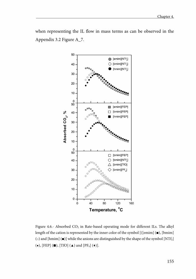
Chapter 4.
155
when representing the IL flow in mass terms as can be observed in the
Appendix 3.2 Figure A_7.
Figure 4.6.- Absorbed CO2 in Rate-based operating mode for different ILs. The alkyl length of the cation is represented by the inner color of the symbol [([emim] (■), [bmim] (□) and [hmim] (■)] while the anions are distinguished by the shape of the symbol [NTf2]
(●), [FEP] (■), [TfO] (▲) and [PF6] (♦)].

Aspen Plus/COSMO-RS Multiscale Ionic Liquid Conceptual Process Design .
156
Figure 4.7.- IL needed to reach a 90% of CO2 absorbed in a Rate-based operating RADFRAC column at different pressures. The inlet temperature of the IL is in its optimum for each point of the graph as shown in Figure 4.5.
It should be emphasized that, if one attends only to thermodynamic
criteria, the best absorbent among the 8 studied ILs would be
[hmim][NTf2] or [hmim][FEP] [114, 146]. These later results should be
ascribed to a combined effect of the high CO2 absorption capacity and the
high CO2 diffusion coefficients of CO2 in [emim][NTf2] and [emim][FEP]
ILs.
3.3.- Regeneration Individual Operation
In this section we analyze a combined pressure and temperature swing
method for the IL regeneration. The feed stream to the swing operation
had 1,000 kmol/h of a mixture containing 10 mole% of CO2 and 90 mole%
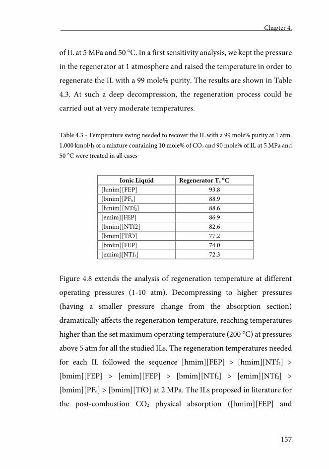
Chapter 4.
157
of IL at 5 MPa and 50 C. In a first sensitivity analysis, we kept the pressure
in the regenerator at 1 atmosphere and raised the temperature in order to
regenerate the IL with a 99 mole% purity. The results are shown in Table
4.3. At such a deep decompression, the regeneration process could be
carried out at very moderate temperatures.
Table 4.3.- Temperature swing needed to recover the IL with a 99 mole% purity at 1 atm. 1,000 kmol/h of a mixture containing 10 mole% of CO2 and 90 mole% of IL at 5 MPa and 50 C were treated in all cases
Ionic Liquid Regenerator T, C [hmim][FEP] 93.8 [bmim][PF6] 88.9 [hmim][NTf2] 88.6 [emim][FEP] 86.9 [bmim][NTf2] 82.6 [bmim][TfO] 77.2 [bmim][FEP] 74.0 [emim][NTf2] 72.3
Figure 4.8 extends the analysis of regeneration temperature at different
operating pressures (1-10 atm). Decompressing to higher pressures
(having a smaller pressure change from the absorption section)
dramatically affects the regeneration temperature, reaching temperatures
higher than the set maximum operating temperature (200 C) at pressures
above 5 atm for all the studied ILs. The regeneration temperatures needed
for each IL followed the sequence [hmim][FEP] > [hmim][NTf2] >
[bmim][FEP] > [emim][FEP] > [bmim][NTf2] > [emim][NTf2] >
[bmim][PF6] > [bmim][TfO] at 2 MPa. The ILs proposed in literature for
the post-combustion CO2 physical absorption ([hmim][FEP] and
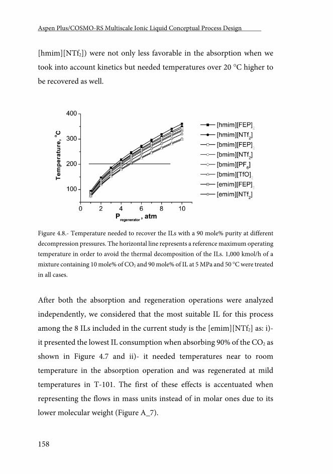
Aspen Plus/COSMO-RS Multiscale Ionic Liquid Conceptual Process Design .
158
[hmim][NTf2]) were not only less favorable in the absorption when we
took into account kinetics but needed temperatures over 20 C higher to
be recovered as well.
Figure 4.8.- Temperature needed to recover the ILs with a 90 mole% purity at different decompression pressures. The horizontal line represents a reference maximum operating temperature in order to avoid the thermal decomposition of the ILs. 1,000 kmol/h of a mixture containing 10 mole% of CO2 and 90 mole% of IL at 5 MPa and 50 C were treated in all cases.
After both the absorption and regeneration operations were analyzed
independently, we considered that the most suitable IL for this process
among the 8 ILs included in the current study is the [emim][NTf2] as: i)-
it presented the lowest IL consumption when absorbing 90% of the CO2 as
shown in Figure 4.7 and ii)- it needed temperatures near to room
temperature in the absorption operation and was regenerated at mild
temperatures in T-101. The first of these effects is accentuated when
representing the flows in mass units instead of in molar ones due to its
lower molecular weight (Figure A_7).
Chapter 4.
159
3.4.- Complete Process
The post-combustion CO2 absorption process by physical absorption with
ILs shown in Figure 4.1 consists of an absorption and regeneration column
interdependent due to the recirculation of the regenerated IL (S-13) from
the bottom of the regeneration unit (T-101) to the first stage of the
absorption tower (T- 100). In this section, we consider the influence that
connecting both sections of the system (i.e. injecting the regenerated IL as
feed stream of the absorber) has in the operating conditions and energy
consumptions of the entire process. It should be noted that the
recirculated stream exiting the regeneration process is not completely
pure in IL since it contains traces of CO2, O2, N2 and H2O dragged from
the absorption column in the first place. We study the economic impact
(as a sum of operating costs) that the absorption and regeneration
pressure, and the regenerated IL purity have in the global CO2 capture
process. Afterwards, when the process is operating at the selected optimal
conditions, we compare the energy consumption with calculations from
literature.
Table 4.4 collects the estimated electrical, refrigeration and steam costs of
the global CO2 capture process using [emim][NTf2] in different operating
conditions. It can be observed that maintaining the, in any case, high
absorption pressure represents the main operating cost source (between
58 and 88 % of the OPEX). The amount of High Pressure steam needed in
E-103 in order to condition the temperature of the IL+CO2 mixture to the
Aspen Plus/COSMO-RS Multiscale Ionic Liquid Conceptual Process Design .
160
regenerator operating temperature represents the next more important
contribution to the OPEX. In Table 4.4, it is shown how higher absorption
pressure requires larger pressurization costs that translates directly into
higher overall OPEX. Higher regeneration pressures at constant
absorption pressure and IL purity requires always higher regeneration
temperatures ending at larger OPEX. At constant absorption and
regeneration pressures, it can be observed that higher IL purity lowers the
OPEX due to needing lower regeneration temperatures and, consequently,
lower amounts of High Pressure Steam. However, in this case, if the
selected IL purity leads to an optimum temperature (as defined before and
represented in Figure 4.5 and 4.6) below 20 C, refrigeration water at 5 C
is needed in order to condition the regenerated IL to the absorption
temperature. The cost of this lower temperature refrigeration water (more
than 10 times higher than water at 20 C) rise the refrigeration cost
increasing the overall OPEX. As shown in the last two scenarios, changing
the operating absorption temperature below and over 20 C has a great
impact on the overall OPEX. The last scenario represented in Table 4.4
corresponds to the optimum conditions of the present study. The
absorption column was set to operate at 2 MPa and 33.3 C and the
regeneration column operates at 1 atmosphere and 168.43 C achieving an
IL purity of 99.5 mole%.
The total calculated operating costs of this optimum scenario was 3.07
M€/year, which corresponds to 73.3 €/ton of captured CO2 (or $83.0/ton
of captured CO2 at the present €/$ exchange). This value is similar to
estimations presented in literature for other processes ($62/ton of
captured CO2 as calculated for a chemical absorption using Aprotic
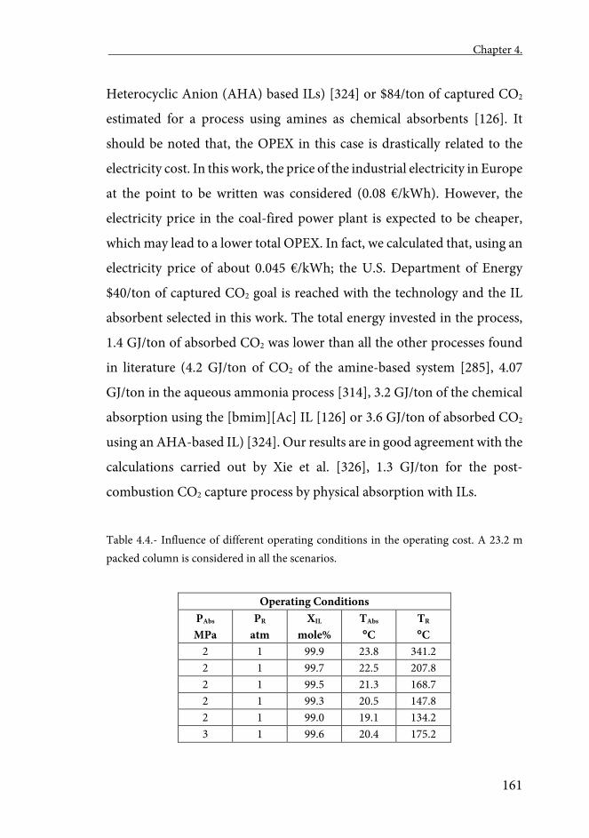
Chapter 4.
161
Heterocyclic Anion (AHA) based ILs) [324] or $84/ton of captured CO2
estimated for a process using amines as chemical absorbents [126]. It
should be noted that, the OPEX in this case is drastically related to the
electricity cost. In this work, the price of the industrial electricity in Europe
at the point to be written was considered (0.08 €/kWh). However, the
electricity price in the coal-fired power plant is expected to be cheaper,
which may lead to a lower total OPEX. In fact, we calculated that, using an
electricity price of about 0.045 €/kWh; the U.S. Department of Energy
$40/ton of captured CO2 goal is reached with the technology and the IL
absorbent selected in this work. The total energy invested in the process,
1.4 GJ/ton of absorbed CO2 was lower than all the other processes found
in literature (4.2 GJ/ton of CO2 of the amine-based system [285], 4.07
GJ/ton in the aqueous ammonia process [314], 3.2 GJ/ton of the chemical
absorption using the [bmim][Ac] IL [126] or 3.6 GJ/ton of absorbed CO2
using an AHA-based IL) [324]. Our results are in good agreement with the
calculations carried out by Xie et al. [326], 1.3 GJ/ton for the post-
combustion CO2 capture process by physical absorption with ILs.
Table 4.4.- Influence of different operating conditions in the operating cost. A 23.2 m packed column is considered in all the scenarios.
Operating Conditions PAbs MPa
PR atm
XIL mole%
TAbs C
TR C
2 1 99.9 23.8 341.2 2 1 99.7 22.5 207.8 2 1 99.5 21.3 168.7 2 1 99.3 20.5 147.8 2 1 99.0 19.1 134.2 3 1 99.6 20.4 175.2
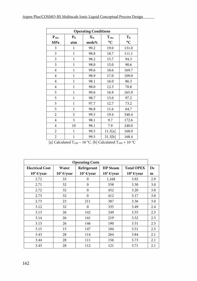
Aspen Plus/COSMO-RS Multiscale Ionic Liquid Conceptual Process Design .
162
Operating Conditions PAbs MPa
PR atm
XIL mole%
TAbs C
TR C
3 1 99.2 19.0 131.0 3 1 98.8 18.7 111.1 3 1 98.2 15.7 94.3 3 1 98.0 15.0 90.6 4 1 99.6 18.6 169.7 4 1 98.9 17.0 109.0 4 1 98.1 16.0 86.3 4 1 98.0 12.3 70.8 5 1 99.6 16.9 165.9 5 1 98.7 15.0 97.2 5 1 97.7 12.7 73.2 5 1 96.8 11.6 64.7 2 5 99.5 19.4 340.4 4 5 98.1 9.7 172.6 4 10 98.1 7.9 240.0 2 1 99.5 11.3[a] 168.9 2 1 99.5 31.3[b] 168.4
[a] Calculated TABS – 10 C. [b] Calculated TABS + 10 C
Operating Costs Electrical Cost
106 €/year Water
103 €/year Refrigerant 103 €/year
HP Steam 103 €/year
Total OPEX 106 €/year
Dc m
2.72 33 0 1,168 3.92 2.9 2.71 32 0 558 3.30 3.0 2.72 32 0 452 3.20 3.0 2.73 32 0 412 3.17 3.0 2.73 23 211 387 3.36 3.0 3.12 32 0 335 3.49 2.4 3.13 26 142 249 3.55 2.5 3.14 26 141 219 3.52 2.5 3.15 26 146 190 3.51 2.5 3.15 15 147 184 3.51 2.5 3.43 28 114 264 3.84 2.1 3.44 28 111 156 3.73 2.1 3.45 28 112 121 3.71 2.1
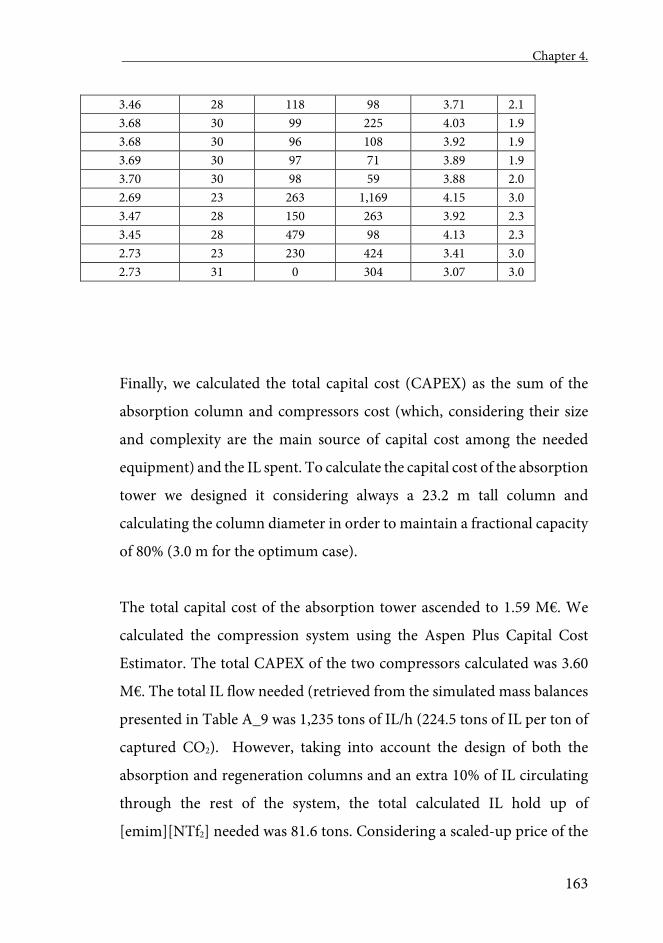
Chapter 4.
163
Finally, we calculated the total capital cost (CAPEX) as the sum of the
absorption column and compressors cost (which, considering their size
and complexity are the main source of capital cost among the needed
equipment) and the IL spent. To calculate the capital cost of the absorption
tower we designed it considering always a 23.2 m tall column and
calculating the column diameter in order to maintain a fractional capacity
of 80% (3.0 m for the optimum case).
The total capital cost of the absorption tower ascended to 1.59 M€. We
calculated the compression system using the Aspen Plus Capital Cost
Estimator. The total CAPEX of the two compressors calculated was 3.60
M€. The total IL flow needed (retrieved from the simulated mass balances
presented in Table A_9 was 1,235 tons of IL/h (224.5 tons of IL per ton of
captured CO2). However, taking into account the design of both the
absorption and regeneration columns and an extra 10% of IL circulating
through the rest of the system, the total calculated IL hold up of
[emim][NTf2] needed was 81.6 tons. Considering a scaled-up price of the
3.46 28 118 98 3.71 2.1 3.68 30 99 225 4.03 1.9 3.68 30 96 108 3.92 1.9 3.69 30 97 71 3.89 1.9 3.70 30 98 59 3.88 2.0 2.69 23 263 1,169 4.15 3.0 3.47 28 150 263 3.92 2.3 3.45 28 479 98 4.13 2.3 2.73 23 230 424 3.41 3.0 2.73 31 0 304 3.07 3.0
Aspen Plus/COSMO-RS Multiscale Ionic Liquid Conceptual Process Design .
164
[emim][NTf2] from 20 to 50 €/kg [64, 165, 340] the total capital cost of the
IL would be in the range of 1.63 M€ to 4.08 M€. We consider 20 €/kg a
very favorable scenario when scaling up the IL price (their prices are
extremely high nowadays) but if applied to such a large scaled process like
the post-combustion CO2 capture, prices this low may be expected. The
total OPEX (3.07 M€/year) was relatively big for a plant this size. This
confirms that the energy penalty in the high-pressure processes like the
physical absorption of CO2 may be their biggest drawback, whereas the
needed equipment cost is comparatively small.
4.- Conclusions
Using powerful professional process simulation tools, such as Aspen Plus,
supposed an advance in the evaluation of ILs for the post-combustion CO2
capture by physical absorption. On the one hand, it incorporates new
technical criteria, key for the selection of the absorbing IL and, on the
other hand, it contributes to perform viability analyses of this technology
through the estimation of operating and capital cost. The process
simulations with rigorous Rate-based methods indicated that the CO2
physical absorption operation using ILs in a commercial packing column
shows an important mass transfer kinetic control. Consequently, we
conclude that the transport properties are key for the selection of the
optimum IL for the efficient separation of CO2. The modeling of the
individual absorption and regeneration operations allowed us to select,
among the 8 thermodynamically selected in literature ILs, the
[emim][NTf2] IL as the best absorbent, due to its low viscosity, high
Chapter 4.
165
absorption capacity and low molecular weight. The Aspen Plus simulation
of the complete CO2 capture process via physical absorption using the
[emim][NTf2] IL as absorbent provided analysis of the effect of the
operating conditions (temperature and pressure of the separation units
and lean solvent purity) in the operating costs. The major contribution to
the total OPEX corresponded to the electrical cost of the compressors and
pumps needed to maintain the process pressure. The optimized total
operating energy in the physical absorption of CO2 is 1.4 GJ/ton of CO2,
which is lower than the reported estimations for other CO2 capture
technologies. However, the OPEX, due to the high electricity prices in the
modeled scenario (in a western European environment), are higher than
other technologies. We also calculated that, in a scenario with lower
electricity prices (China or the U.S., for instance), the technology and IL
selected in this work may be within reach of the U.S. Department of
Energy goal ($40/ton of captured CO2).
With the aim of advancing in the possible application of ILs for the CO2
capture from post-combustion streams, in the future, we will apply our
COSMO-based methodology to the simulation of processes that require
lower pressures: the absorption of CO2 with ILs that promote the chemical
capture of CO2 or the absorption using ILs with improved properties as
physical absorbents.

Chapter 5 Aspen Plus supported analysis of the post-combustion CO2
capture by chemical absorption using the AHA Ionic Liquids
[P2228][CNPyr] and [P66614][CNPyr].

Chapter 5
169
Chapter 5
Aspen Plus supported analysis of the post-combustion CO2 capture by chemical absorption using the AHA Ionic Liquids
[P2228][CNPyr] and [P66614][CNPyr].
Abstract
In this work, the post-combustion CO2 chemical capture using the
[P2228][CNPyr] and the [P66614][CNPyr] Aprotic Heterocyclic Anion Ionic
Liquids is analyzed. To model the unit operations in a commercial process
simulator (Aspen Plus), a multiscale a priori methodology developed in
our group is used to include the ionic liquid into the simulator database.
This methodology takes advantages of computational chemistry (Tmolex
molecular simulations) and combined quantum chemistry and
thermodynamics (COSMO-RS) to efficiently and inexpensively predict
the component properties needed to include new non-databank
compounds into the AspenOne suite of programs database. First, the
absorption operation is simulated using the RADFRAC rigorous model
both in Rate-based (mass transfer limitations considered) and
Equilibrium modes. The heat of reaction is considered and related to the
mass transfer kinetics. Tetraglyme is proposed as a co-solvent able to both
improve the concentration of CO2 present in liquid phase and completely
eliminate the mass transfer limitations. Secondly, the regeneration column
is simulated using the same rigorous RADFRAC model. The
multicomponent desorption (CO2 and H2O must be desorbed) is
Aspen Plus/COSMO-RS Multiscale Ionic Liquid Conceptual Process Design .
170
calculated and analyzed. A recirculation of CO2 is proposed as stripping
fluid.
1.- Introduction
Coal-fired power plants are, undoubtedly, a major source of greenhouse
gas emission. They are and will continue to be (at least until 2040) a
relevant source of electricity worldwide [111, 281]. Both academia and
industry are making efforts to solve or, at least mitigate, their
environmental impact. International (The Intergovernmental Panel on
Climate Change (IPCC), The United Nations Environment Programme
(UNEP), OECDs Environment Policy Committee (EPOC), etc.) and
national (The U.S. Environmental Protection Agency, The Ministry of
Environmental Protection of China, The European Environment Agency,
etc.) environmental protection institutions have been supporting these
efforts. The implementation of restrictive laws (Clean Power Plan of the
US [341], China’s National Climate Change Programme (National
Development and Reform Commission, 2015), etc.), and international
agreements (the recently signed Paris Agreement (United Nations, 2015),
for instance) or the direct research funding are accelerating the research
in this field. One way of mitigating some of the environmental effects that
the coal-fired power plants have is by capturing the emitted CO2 of the
post-combustion Flue Gas stream that exits the plant with a CO2 partial
pressure of around 0.13 bar. Nowadays, aqueous amines based processes
(especially those using monoethanolamine (MEA) solutions) are the most
promising carbon capture technologies for post-combustion CO2
Chapter 5
171
capturing [342]. This processes present, however, several drawbacks that
keep the research of alternatives meaningful: corrosion [343], solvent loss
[344, 345], high energy requirements and great water consumption [346]
are among the most relevant disadvantages.
One alternative to aqueous amines is the use of Ionic Liquids (ILs) as
absorbents. In the early 2000s some ILs with high CO2 solubility were
identified [290, 291]. Their absorption capacity was too small and the
pressure that the process needed too high, so research groups started to
seek new ILs capable of chemically absorb CO2. The first Task Specific
Ionic Liquids (TSILs) able to do so presented a capacity of around 0.5
moles of absorbed CO2 per mol of IL was identified in 2002 by Bates et al.
[347]. After, Zhang et al. [348], reported that including amino-
functionalized groups to the IL structure, the capacity rises to 1 mol of CO2
per mol of IL. However, the product of the absorption was more viscous
than the already viscous lean IL making the process unpractical.
Theoretical simulations [123] demonstrated that the creation of large
hydrogen bonding networks was responsible of raising the product
viscosity. Isolating the amino groups in the anion reduced hydrogen
bonding possibilities and, therefore, the product viscosity was similar to
the original ILs [71]. This new type of ILs with Aprotic Heterocyclic
Anions are called AHAs [125]. They are a promising type of amino-
functionalized ILs with a theoretical chemical capacity of 1 mol of CO2 per
mol of IL and do not present a viscosity increase after reaction. However,
the viscosity of AHAs is high compared to other conventional solvents
having unfavorable transport properties that may affect drastically the
separation process and the IL selection as it implies important mass
Aspen Plus/COSMO-RS Multiscale Ionic Liquid Conceptual Process Design .
172
transfer kinetic control [349]. In order to perform a complete feasibility
study, therefore, the consideration of mass transfer kinetic aspects in a
realistic environment is necessary for these processes.
In the last years, our group has introduced a multiscale tool [215] that
allows the implementation of non-databank components into commercial
process simulators (Aspen Hysys and Aspen Plus) with which we have
studied many ILs’ applications. Within the studied applications, it is
especially relevant for this work the modeling of CO2 physical capture
operations with ILs [84]. In that work we used rigorous columns able to
take into consideration the mass transfer limitations, revealing the
extreme importance of such calculations to realistically model this type of
processes. The analysis of CO2-AHA isotherms shows that at partial
pressures corresponding to post-combustion streams (0.13 bar) and
temperatures close to the environment, the CO2-IL reaction is not
quantitative, reaching conversions close to 50% and remaining, therefore,
non-reacted IL in the product stream. Additionally, due to the ILs’ high
viscosity, processes involving ILs as solvents in liquid-gas operations can
be mass transfer controlled [84, 162].
One main contribution of this work is proposing the use of Tetraglyme
(TG) as a co-solvent able to both reduce the solvent phase viscosity (TG’s
viscosity at 25 C is 0.8 cP) and, at the same time, increase the amount of
CO2 in the liquid phase (due to the relatively high CO2 solubility in TG)
displacing, therefore, the chemical reaction towards products, and
increasing the utilization factor of the IL. TG, at the same time, maintain
very low volatility, in addition to high thermal and chemical stability (even
Chapter 5
173
in presence of the AHA). TG was already used by Gurkan et al. (2013)
[124] to eliminate diffusion limitations when measuring reaction kinetics
at lab scale. In that work, the stability of TG in AHA ILs was proven. They
provided the physical solubility of CO2 in TG which will be used for
validation purposes in this work. Slightly larger CO2 solubility may be
expected if compared to the Henry constants calculated for CO2 in ILs that
only present physical absorption [114].
The IL regeneration is another determining factor in the process economy.
It should be noted that, the exothermic chemical absorption requires
raising the temperature to reverse the reaction. On the other hand, the
post-combustion streams may contain high percentages of water (up to
7%), which, in practice, involves carrying out a multi-component
desorption process capable of desorbing compounds of very different
volatility (CO2 and H2O). Conventional process designs for the
regeneration of chemically absorbed CO2 propose doing so with a high-
pressure steam stripping. Even though this might be adequate for amine-
based processes (where the aqueous solution is desirable), taking into
account the high-water absorption capacities of the AHAs, the additional
water would represent an unnecessary extra load to the regeneration
column that must be, desorbed from the IL. Therefore, the other main
contribution of this work is to propose to reuse part of the CO2 as stripping
fluid with the premise that it will be a better stripping gas to desorb water
(as its addition lowers the H2O partial pressure) without affecting the CO2
desorption performance (due to its higher volatility).
Aspen Plus/COSMO-RS Multiscale Ionic Liquid Conceptual Process Design .
174
For these purposes, a detailed evaluation of the [P2228][CNPyr] and the
[P66614][CNPyr] AHA ILs in the post-combustion CO2 capture process
(including thermodynamic, kinetic, technical and economic aspects) is
carried out. The process is modeled using the commercial Aspen Plus
process simulator and the multiscale approach developed in our group
and adapted to ILs [153, 215]; we studied both the absorption and
regeneration individual operations. The RADFRAC rigorous model as
implemented in Aspen Plus was used to calculate the absorption
operation. This model can be used to calculate the separation performance
in Equilibrium (mass transfer kinetics not considered) and Rate-based
modes (where the possible mass transfer control is calculated). Attending
to the energy balance, the model can calculate the separation in isothermal
(heat of reaction not considered) and adiabatic modes (with heat of
reaction = -43 kJ/mol as calculated in Gurkan et al. (2010) [123]. We
selected the absorption temperature studying its effect in the CO2 capture
performance in the four possible column configurations (from more ideal
to the most realistic: Equilibrium & isothermic, Equilibrium & Adiabatic,
Rate-based & isothermic, and Rate-Based & Adiabatic). We analyzed the
effect of adding TG in the amount of physically and chemically absorbed
CO2, the operating temperature, the solvent phase viscosity and the size of
the absorption column. These analyses allowed us to select an optimal
AHA/TG feeding ratio. Afterwards, we studied the regeneration
operation. The regeneration column was modeled a part of the produced
CO2 as stripping gas with the energy cost using high using the same
RADFRAC Aspen Plus model operating in Rate-based and adiabatic
mode (the most realistic mode). We compared the energy needs of using
a part of the produced CO2 as stripping gas with the energy cost using high
Chapter 5
175
pressure steam to strip the CO2 and the H2O. We selected the optimal
amount of CO2 that needs to be recycled to the regeneration column with
the calculated energy as objective function.
2.- Computational Details
2.1.- Component Definition and Thermodynamic Model Specification
The procedure used to implement new components in the simulator and
to create simulations involving these non-databank components in the
Aspen Properties system has been already disclosed with more detail in
previous publications [56, 57, 80, 81, 84, 153, 162, 163, 350]. The chemical
reaction between the IL and the CO2 (1 mol of [P2228][CNPyr]/1 mol of
[P66614][CNPyr]+ 1 mol of CO2 to produce 1 mol of Product) has to be
modeled. Quantum chemical calculations of both the IL and the product
component were carried out and both components were included in the
Aspen Properties system using the same procedure as in previous works.
COSMO-RS calculations (using COSMOthermX version C 30 1201 and
the BP TZVP C30 1201 default parametrization) were used to retrieve the
information needed to create the components (using the
pseudocomponent method) within Aspen Plus and to specify the
COSMOSAC. The viscosity-to-temperature dependent data was fitted to
an Arrhenius type model using the procedure explained in a previous
work [77]. In this case, additionally, the composition dependent viscosity
data was fitted to a composition dependent term (Eq 5.1):
Aspen Plus/COSMO-RS Multiscale Ionic Liquid Conceptual Process Design .
176
ln�𝑚𝑚𝑚𝑚𝑥𝑥� = ln�1� · 𝑥𝑥1 + ln�2� · 𝑥𝑥2 + �𝑅𝑅𝑚𝑚 + 𝐵𝐵𝑚𝑚𝑇𝑇� � · 𝑥𝑥1 · 𝑥𝑥2 Eq 5.1
where,
ln�𝑖𝑖� = �𝑅𝑅𝑖𝑖 + 𝐵𝐵𝑖𝑖𝑇𝑇� � Eq 5.2
This reaction is exothermic, and the heat of reaction has been calculated
to be around -43 kJ/mol of absorbed CO2 [123]. An arbitrary enthalpy of
formation of the product component was selected varying the enthalpy of
formation of the IL in order to adjust a heat of reaction of -43 kJ/mol
following Aspen Tech’s recommended procedure (Aspen Plus knowledge
base item 102,309).
2.2.- Post-combustion CO2 Stream Characteristics.
The modeled Flue Gas to be treated has the characteristics summarized in
Table 5.1; a similar composition to the one produced in a traditional coal-
fired power plant according to Case B11 from the 2015 Rev.3 Department
of Energy (DOE) Cost and Performance Baseline for Fossil Energy Plants
Volume 1a [328]. This is the same post-combustion stream as the one we
already modeled in [84].Sulfur dioxide is not included in this composition
since any residual sulfur dioxide from the Flue Gas desulphurization
system is considered removed prior to entering the CO2 capture unit. We
calculated that the previous dehydration unit during the pre-compression
of the Flue Gas removed 92.1 % of the water (67.3 kmol/h) before getting
to the absorption section.
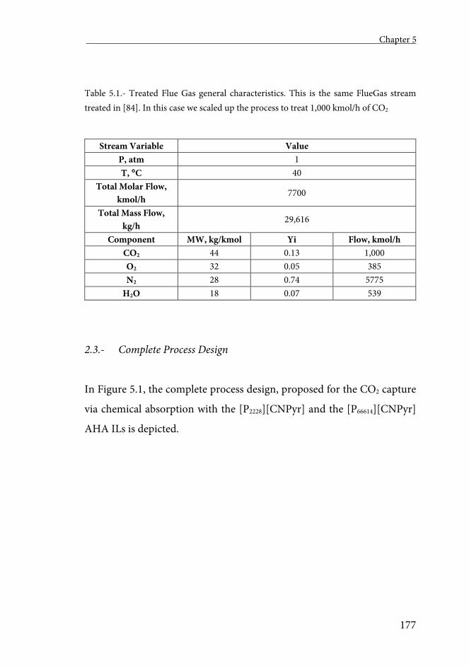
Chapter 5
177
Table 5.1.- Treated Flue Gas general characteristics. This is the same FlueGas stream treated in [84]. In this case we scaled up the process to treat 1,000 kmol/h of CO2
Stream Variable Value P, atm 1 T, C 40
Total Molar Flow, kmol/h
7700
Total Mass Flow, kg/h
29,616
Component MW, kg/kmol Yi Flow, kmol/h CO2 44 0.13 1,000 O2 32 0.05 385 N2 28 0.74 5775
H2O 18 0.07 539
2.3.- Complete Process Design
In Figure 5.1, the complete process design, proposed for the CO2 capture
via chemical absorption with the [P2228][CNPyr] and the [P66614][CNPyr]
AHA ILs is depicted.
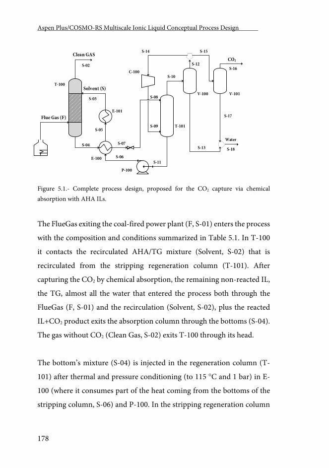
Aspen Plus/COSMO-RS Multiscale Ionic Liquid Conceptual Process Design .
178
T-100
T-101
E-100
Clean GAS
Solvent (S)V-100 V-101
C-100
CO2
Flue Gas (F)
S-02
S-03
S-04
S-05
S-06
S-07
S-10
S-12
S-14 S-15
S-13
S-16
S-17
S-18
P-100
E-101
S-08
S-09
S-11
Water
Figure 5.1.- Complete process design, proposed for the CO2 capture via chemical absorption with AHA ILs.
The FlueGas exiting the coal-fired power plant (F, S-01) enters the process
with the composition and conditions summarized in Table 5.1. In T-100
it contacts the recirculated AHA/TG mixture (Solvent, S-02) that is
recirculated from the stripping regeneration column (T-101). After
capturing the CO2 by chemical absorption, the remaining non-reacted IL,
the TG, almost all the water that entered the process both through the
FlueGas (F, S-01) and the recirculation (Solvent, S-02), plus the reacted
IL+CO2 product exits the absorption column through the bottoms (S-04).
The gas without CO2 (Clean Gas, S-02) exits T-100 through its head.
The bottom’s mixture (S-04) is injected in the regeneration column (T-
101) after thermal and pressure conditioning (to 115 C and 1 bar) in E-
100 (where it consumes part of the heat coming from the bottoms of the
stripping column, S-06) and P-100. In the stripping regeneration column
Chapter 5
179
(T-101), this multicomponent stream is separated into the regenerated
solvent AHA/TG mixture (S-11) that will carry some of the water and the
gas (S-10) that would be composed of the captured CO2 and the rest of the
water. In T-101, the chemically absorbed CO2 will be desorbed because of
the equilibrium swift towards reactants (because of the temperature and
pressure in which T-101 is operating). This desorbed CO2 and an extra
CO2 injected through the bottom of the tower (S-09) produce the
desorption of both the CO2 and the water contained in S-08.
The S-10 stream, which contains CO2 and water, is introduced into a two-
step biphasic separation train (V-100 and V-101). In V-100, some of the
water (S-13) is separated through bottoms while all the CO2 exits the
column through the head. This CO2 (S-12) is separated into S-14 that will
be compressed and injected to T-101 to act as gas carrier and S-15 that is
introduced into the second biphasic separation vessel (V-101). In such
vessel, the remaining water is separated from the final CO2 that must,
afterwards be compressed and stored.
2.4.- Absorption Individual Column
The absorber was modeled using the RADFRAC Aspen Plus model
operating both in Equilibrium and Rate-based (formerly called RateSep)
modes of operation and with the reaction module enabled. Both the
isothermal (setting the heat of reaction to 0 kJ/mol) and adiabatic (more
realistic) scenarios were considered. For each IL, four different columns
were calculated, two equilibrium columns (working in isothermal and
Aspen Plus/COSMO-RS Multiscale Ionic Liquid Conceptual Process Design .
180
adiabatic modes) and two Rate-based columns (working also in
isothermal and adiabatic modes). For the [P66614][CNPyr] IL, the chemical
reaction was specified using the experimental kinetic expressions of the
direct and reverse reactions [124]. For the [P2228][CNPyr] AHA similar
experiments were carried out in our lab at three different temperatures.
The reaction kinetic equations were, then, transformed into the React-
Distil equilibrium reaction equations as implemented in Aspen Plus. 1
kmol of CO2 was treated with 1 kmol of IL in an absorption column
working at 0.26 atm (which correspond to the CO2 partial pressure of a
stream containing 0.13 molar fraction of CO2 when the absorber operates
at 2 bar). This concentration corresponds to a post-combustion FlueGas
produced in a traditional coal-fired power plant as already shown in Table
5.1. The equilibrium column was specified to have two theoretical stages
while the rate-based column was designed to be 15m high and had a
variable diameter able to maintain a fractional capacity of 80% in all the
process simulations. The Flexypak 700Y structured packing was selected
for this column.
After selecting the size and internals of the column, the temperature
influence in the CO2 uptake was analyzed both in Equilibrium and Rate-
based modes, in both isothermal and adiabatic modes of operation. The
temperature was varied from 15 to 150 C. Afterwards, the addition of TG
to the system at the selected temperature was studied varying the amount
of TG maintaining constant the amount of IL reaching compositions of
TG of up to the 75%. With this sensitivity analysis, the effect of adding TG
in the amount of physically and chemically absorbed CO2, the operating
temperature, and the solvent phase viscosity were the studied variables.
Chapter 5
181
Once the influence of adding TG has been calculated, a more realistic
model was calculated. To do so, we took into consideration the realistic
stream shown in Table 5.1. We consider the streams cooled to 40 C and
at atmospheric pressure (1 atm)
When including the rest of the mixture components, the amount of the
IL/TG mixture needed to capture 80% of the injected CO2 is calculated.
After doing so, we considered the exiting liquid stream as the inlet for the
regeneration column.
2.5.- Regeneration Individual Column
As already explained, the regeneration operation (T-101) of this process is
a multicomponent desorption (both water and CO2 need to be desorbed).
In this case, water need to be desorbed in rates enough to avoid system
accumulation (i.e., the same amount of water entering the system through
the FlueGas need to be desorbed). Because part of the water in the
desorption operation would return to the absorption column, we needed
to calculate the amount of water that is recycled from such operation. To
do so, we supposed that the regenerated IL mixture (S-11) exiting the
regeneration column (T-101) must be saturated in water. To calculate the
amount of water, we used a RADFRAC separation model in the
regeneration conditions (115 C and 1 bar) and calculate the amount of
water (steam in such conditions) able to be absorbed by the stream exiting
the absorber and entering the regeneration column (S-08).
Aspen Plus/COSMO-RS Multiscale Ionic Liquid Conceptual Process Design .
182
With the inlet stream modeled, the regeneration column is calculated
using the same RADFRAC rigorous model we used to model the
absorption operation, including, the same React-Distil reaction and 2
stages. Because of the higher temperatures this operation is carried out at,
we can consider the mass transfer limitation to be insignificant. We
studied the effect of adding recycled CO2 gas as a carrier in such
desorption. Adding incremental amounts of CO2 and observing the
impact in the amount of water that needs to be recirculated, i.e., in the
water saturation composition.
3.- Results
3.1.- Property Validation
Aspen Plus calculation of the Equilibrium isotherms of the [P2228][CNPyr]
+ CO2 and the [P66614][CNPyr] + CO2 reactions were compared to the
experimental data in order to validate our implementation procedure.
Figure 5.2 represent the experimental and calculated isotherms.
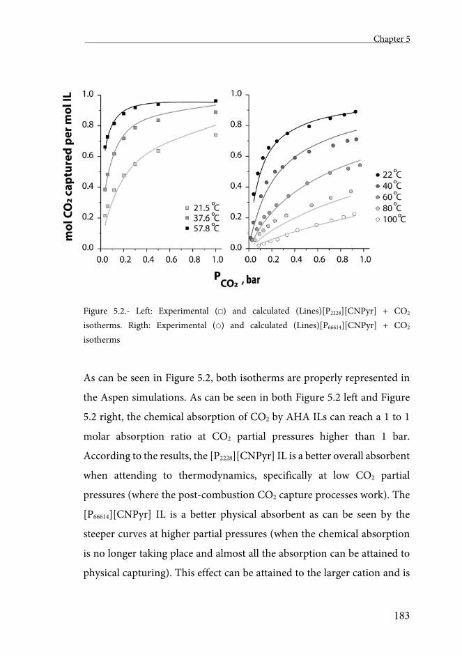
Chapter 5
183
Figure 5.2.- Left: Experimental () and calculated (Lines)[P2228][CNPyr] + CO2 isotherms. Rigth: Experimental () and calculated (Lines)[P66614][CNPyr] + CO2 isotherms
As can be seen in Figure 5.2, both isotherms are properly represented in
the Aspen simulations. As can be seen in both Figure 5.2 left and Figure
5.2 right, the chemical absorption of CO2 by AHA ILs can reach a 1 to 1
molar absorption ratio at CO2 partial pressures higher than 1 bar.
According to the results, the [P2228][CNPyr] IL is a better overall absorbent
when attending to thermodynamics, specifically at low CO2 partial
pressures (where the post-combustion CO2 capture processes work). The
[P66614][CNPyr] IL is a better physical absorbent as can be seen by the
steeper curves at higher partial pressures (when the chemical absorption
is no longer taking place and almost all the absorption can be attained to
physical capturing). This effect can be attained to the larger cation and is
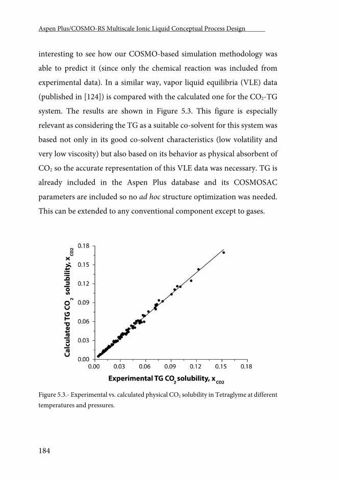
Aspen Plus/COSMO-RS Multiscale Ionic Liquid Conceptual Process Design .
184
interesting to see how our COSMO-based simulation methodology was
able to predict it (since only the chemical reaction was included from
experimental data). In a similar way, vapor liquid equilibria (VLE) data
(published in [124]) is compared with the calculated one for the CO2-TG
system. The results are shown in Figure 5.3. This figure is especially
relevant as considering the TG as a suitable co-solvent for this system was
based not only in its good co-solvent characteristics (low volatility and
very low viscosity) but also based on its behavior as physical absorbent of
CO2 so the accurate representation of this VLE data was necessary. TG is
already included in the Aspen Plus database and its COSMOSAC
parameters are included so no ad hoc structure optimization was needed.
This can be extended to any conventional component except to gases.
Figure 5.3.- Experimental vs. calculated physical CO2 solubility in Tetraglyme at different temperatures and pressures.
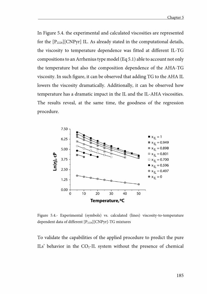
Chapter 5
185
In Figure 5.4. the experimental and calculated viscosities are represented
for the [P2228][CNPyr] IL. As already stated in the computational details,
the viscosity to temperature dependence was fitted at different IL-TG
compositions to an Arrhenius type model (Eq 5.1) able to account not only
the temperature but also the composition dependence of the AHA-TG
viscosity. In such figure, it can be observed that adding TG to the AHA IL
lowers the viscosity dramatically. Additionally, it can be observed how
temperature has a dramatic impact in the IL and the IL-AHA viscosities.
The results reveal, at the same time, the goodness of the regression
procedure.
Figure 5.4.- Experimental (symbols) vs. calculated (lines) viscosity-to-temperature dependent data of different [P2228][CNPyr]-TG mixtures
To validate the capabilities of the applied procedure to predict the pure
ILs’ behavior in the CO2-IL system without the presence of chemical
Aspen Plus/COSMO-RS Multiscale Ionic Liquid Conceptual Process Design .
186
reaction please refer to the already published papers in which this
methodology has been applied [84, 165].
3.2.- Absorption Individual Column
In this section, the results of different sensitivity analyses used to select the
absorption operating conditions, key for understanding the proposed
absorption, are presented.
In a first study, a comparison of the four designed (equilibrium &
isothermal, equilibrium & adiabatic, Rate-based & isothermal and Rate-
based & adiabatic) columns at different inlet temperatures (of both the
solvent and FlueGas) is presented. The temperatures were varied from 15
to 150 C. The capacity in terms of moles of absorbed CO2 per mole of
used IL for the four designed columns and both [P2228][CNPyr] and
[P66614][CNPyr] are presented in Figure 5.5. In this figure, it can be
observed how the different modes of operation affect the AHA utilization
factor (the CO2 absorption ratio).
In the isothermal and equilibrium mode of operation, the absorption is
calculated taking into account, only, the equilibrium at the inlet
temperature since there is not temperature variation along the column.
Analyzing Figure 5.5 left, the one corresponding to the [P2228][CNPyr]
AHA IL, we can observe that in such conditions, the absorbed CO2 at each
temperature can be calculated using the information presented in Figure
5.2 at 0.26 bar (the working CO2 partial pressure) and at the corresponding
Chapter 5
187
temperature. For example, at 40 C, 0.5 moles of CO2 per mole of
[P2228][CNPyr] IL are captured. When the Rate-based correction is applied
to the column, this value decreases to 0.44. This effect is greater at lower
temperatures and is caused by the higher solvent viscosities at lower
temperatures. Considering the heat of reaction, the Adiabatic &
Equilibrium dashed line, the separation dramatically descends from 0.5 to
0.31 moles of CO2 per mol of AHA IL. If further Rate-based correction is
applied to this later calculation, almost no change in the absorption
capacity is observed. In this case, because of the heat of reaction (-43
kJ/mol) of the CO2 absorption reaction, the solvent inside the absorption
column is operating at around 57 C (the temperature of both the FlueGas
and solvent is increasing by 17 C). This temperature increase produces
the already cited capacity decrease while explaining, at the same time, the
negligible difference between the Equilibrium and Rate-based columns
working in adiabatic. At such elevated temperature, the AHA IL viscosity
descends so that no mass transfer limitation is occurring. Similar
conclusions can be obtained observing Figure 5.5 right (the one
corresponding to the [P66614][CNPyr] AHA IL).
With these results in mind, 40 C inlet temperature for the FlueGas and
Solvent streams were selected since operating at lower temperatures would
have consequences when using cold water as refrigerant. When
comparing the [P2228][CNPyr] and [P66614][CNPyr] ILs it can be observed
how, even though, a priori, we might think that [P2228][CNPyr] is a better
absorbent than [P66614][CNPyr] in every scenario (it has better absorption
capacities and lower viscosities), when simulating the most realistic
scenario (Adiabatic & Rate-based), both ILs behave very similarly. This
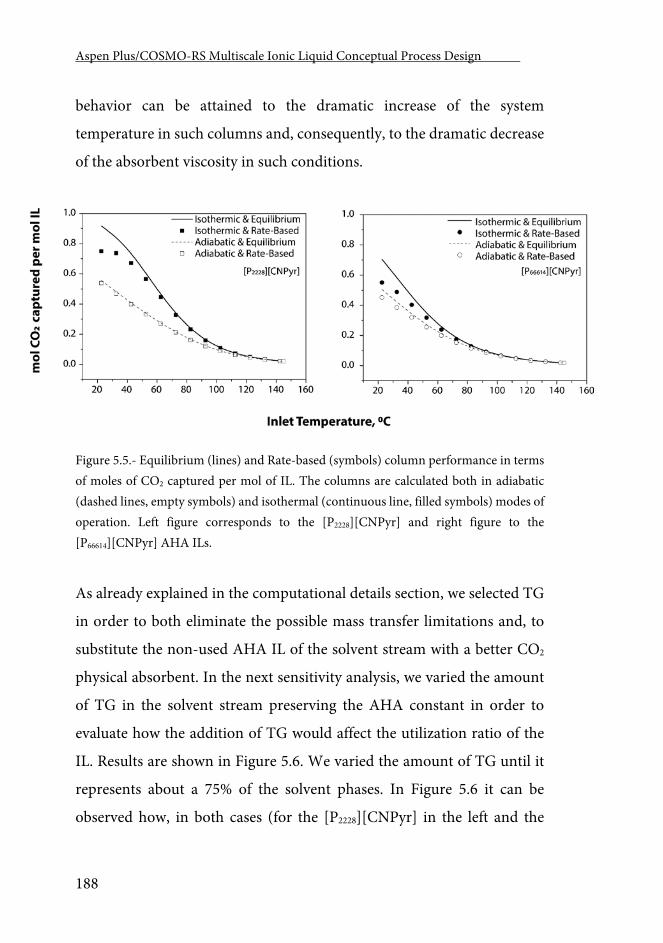
Aspen Plus/COSMO-RS Multiscale Ionic Liquid Conceptual Process Design .
188
behavior can be attained to the dramatic increase of the system
temperature in such columns and, consequently, to the dramatic decrease
of the absorbent viscosity in such conditions.
Figure 5.5.- Equilibrium (lines) and Rate-based (symbols) column performance in terms of moles of CO2 captured per mol of IL. The columns are calculated both in adiabatic (dashed lines, empty symbols) and isothermal (continuous line, filled symbols) modes of operation. Left figure corresponds to the [P2228][CNPyr] and right figure to the [P66614][CNPyr] AHA ILs.
As already explained in the computational details section, we selected TG
in order to both eliminate the possible mass transfer limitations and, to
substitute the non-used AHA IL of the solvent stream with a better CO2
physical absorbent. In the next sensitivity analysis, we varied the amount
of TG in the solvent stream preserving the AHA constant in order to
evaluate how the addition of TG would affect the utilization ratio of the
IL. Results are shown in Figure 5.6. We varied the amount of TG until it
represents about a 75% of the solvent phases. In Figure 5.6 it can be
observed how, in both cases (for the [P2228][CNPyr] in the left and the
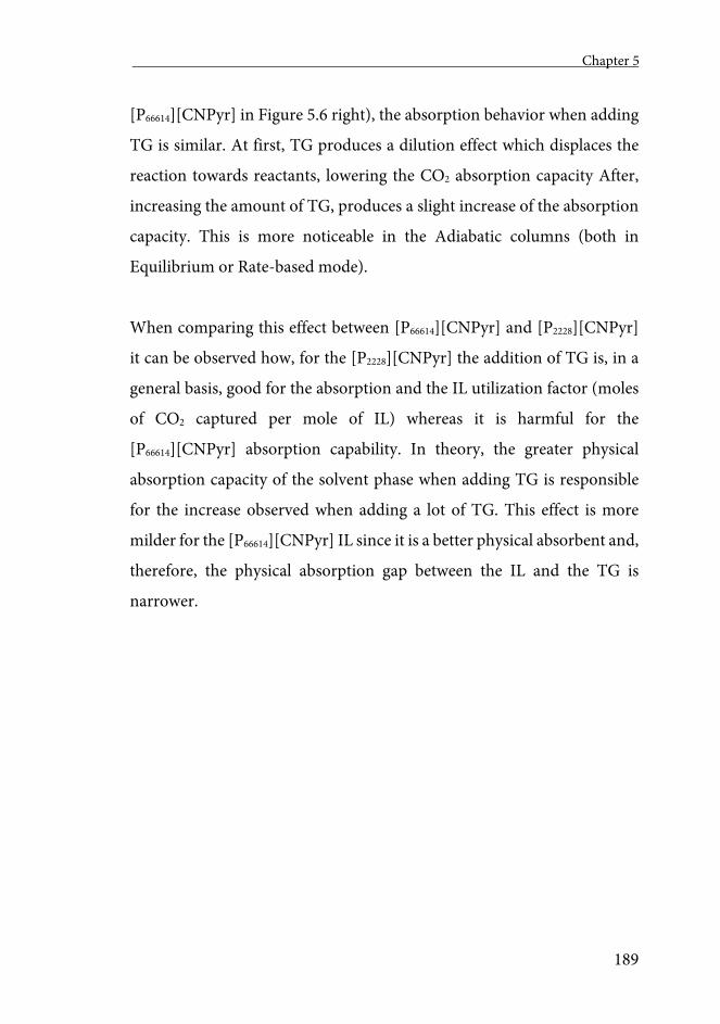
Chapter 5
189
[P66614][CNPyr] in Figure 5.6 right), the absorption behavior when adding
TG is similar. At first, TG produces a dilution effect which displaces the
reaction towards reactants, lowering the CO2 absorption capacity After,
increasing the amount of TG, produces a slight increase of the absorption
capacity. This is more noticeable in the Adiabatic columns (both in
Equilibrium or Rate-based mode).
When comparing this effect between [P66614][CNPyr] and [P2228][CNPyr]
it can be observed how, for the [P2228][CNPyr] the addition of TG is, in a
general basis, good for the absorption and the IL utilization factor (moles
of CO2 captured per mole of IL) whereas it is harmful for the
[P66614][CNPyr] absorption capability. In theory, the greater physical
absorption capacity of the solvent phase when adding TG is responsible
for the increase observed when adding a lot of TG. This effect is more
milder for the [P66614][CNPyr] IL since it is a better physical absorbent and,
therefore, the physical absorption gap between the IL and the TG is
narrower.
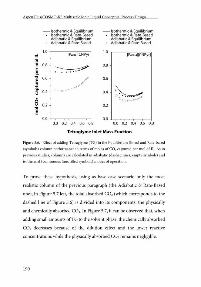
Aspen Plus/COSMO-RS Multiscale Ionic Liquid Conceptual Process Design .
190
Figure 5.6.- Effect of adding Tetraglyme (TG) in the Equilibrium (lines) and Rate-based (symbols) column performance in terms of moles of CO2 captured per mol of IL. As in previous studies, columns are calculated in adiabatic (dashed lines, empty symbols) and isothermal (continuous line, filled symbols) modes of operation.
To prove these hypothesis, using as base case scenario only the most
realistic column of the previous paragraph (the Adiabatic & Rate-Based
one), in Figure 5.7 left, the total absorbed CO2 (which corresponds to the
dashed line of Figure 5.6) is divided into its components: the physically
and chemically absorbed CO2. In Figure 5.7, it can be observed that, when
adding small amounts of TG to the solvent phase, the chemically absorbed
CO2 decreases because of the dilution effect and the lower reactive
concentrations while the physically absorbed CO2 remains negligible.
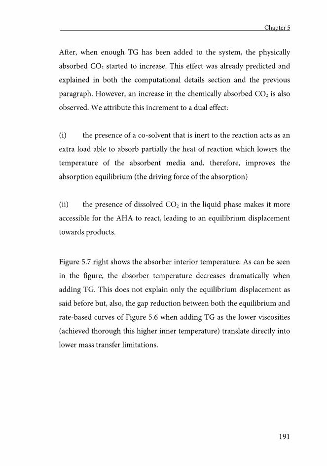
Chapter 5
191
After, when enough TG has been added to the system, the physically
absorbed CO2 started to increase. This effect was already predicted and
explained in both the computational details section and the previous
paragraph. However, an increase in the chemically absorbed CO2 is also
observed. We attribute this increment to a dual effect:
(i) the presence of a co-solvent that is inert to the reaction acts as an
extra load able to absorb partially the heat of reaction which lowers the
temperature of the absorbent media and, therefore, improves the
absorption equilibrium (the driving force of the absorption)
(ii) the presence of dissolved CO2 in the liquid phase makes it more
accessible for the AHA to react, leading to an equilibrium displacement
towards products.
Figure 5.7 right shows the absorber interior temperature. As can be seen
in the figure, the absorber temperature decreases dramatically when
adding TG. This does not explain only the equilibrium displacement as
said before but, also, the gap reduction between both the equilibrium and
rate-based curves of Figure 5.6 when adding TG as the lower viscosities
(achieved thorough this higher inner temperature) translate directly into
lower mass transfer limitations.
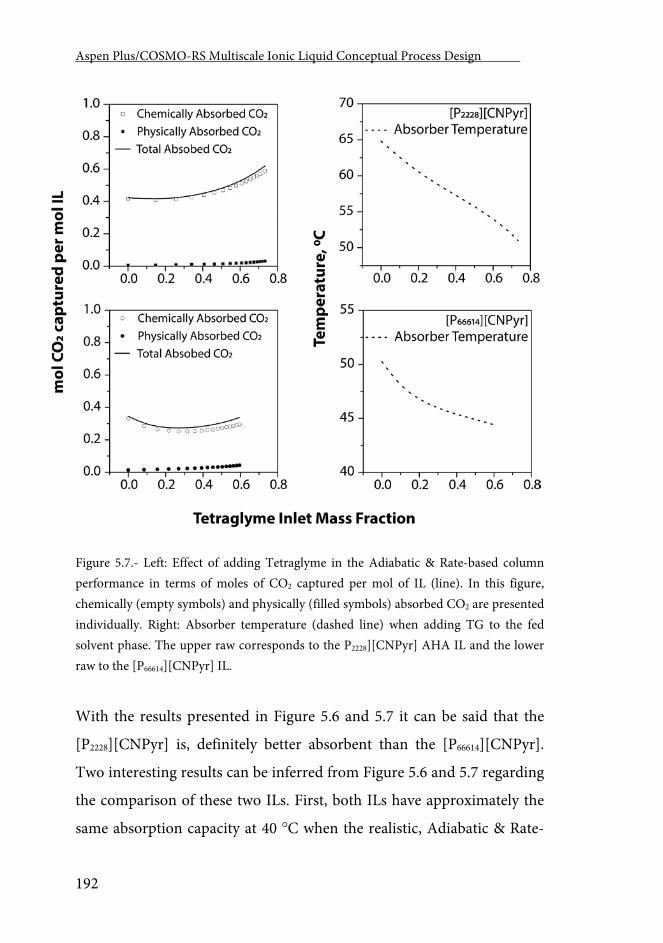
Aspen Plus/COSMO-RS Multiscale Ionic Liquid Conceptual Process Design .
192
Figure 5.7.- Left: Effect of adding Tetraglyme in the Adiabatic & Rate-based column performance in terms of moles of CO2 captured per mol of IL (line). In this figure, chemically (empty symbols) and physically (filled symbols) absorbed CO2 are presented individually. Right: Absorber temperature (dashed line) when adding TG to the fed solvent phase. The upper raw corresponds to the P2228][CNPyr] AHA IL and the lower raw to the [P66614][CNPyr] IL.
With the results presented in Figure 5.6 and 5.7 it can be said that the
[P2228][CNPyr] is, definitely better absorbent than the [P66614][CNPyr].
Two interesting results can be inferred from Figure 5.6 and 5.7 regarding
the comparison of these two ILs. First, both ILs have approximately the
same absorption capacity at 40 C when the realistic, Adiabatic & Rate-
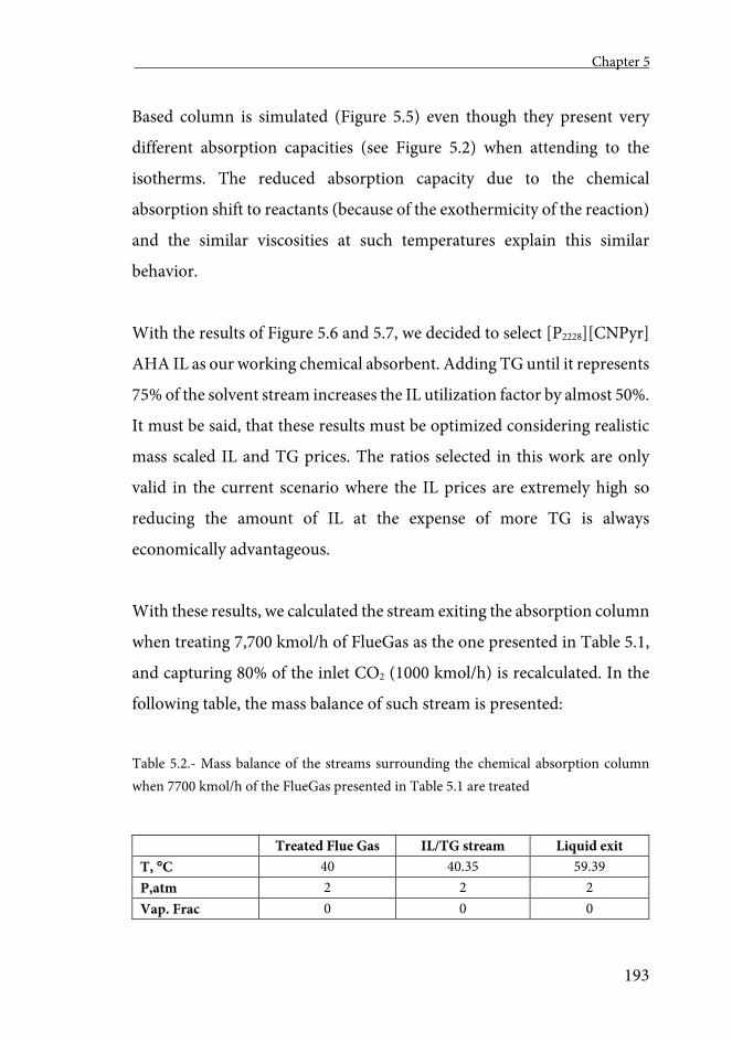
Chapter 5
193
Based column is simulated (Figure 5.5) even though they present very
different absorption capacities (see Figure 5.2) when attending to the
isotherms. The reduced absorption capacity due to the chemical
absorption shift to reactants (because of the exothermicity of the reaction)
and the similar viscosities at such temperatures explain this similar
behavior.
With the results of Figure 5.6 and 5.7, we decided to select [P2228][CNPyr]
AHA IL as our working chemical absorbent. Adding TG until it represents
75% of the solvent stream increases the IL utilization factor by almost 50%.
It must be said, that these results must be optimized considering realistic
mass scaled IL and TG prices. The ratios selected in this work are only
valid in the current scenario where the IL prices are extremely high so
reducing the amount of IL at the expense of more TG is always
economically advantageous.
With these results, we calculated the stream exiting the absorption column
when treating 7,700 kmol/h of FlueGas as the one presented in Table 5.1,
and capturing 80% of the inlet CO2 (1000 kmol/h) is recalculated. In the
following table, the mass balance of such stream is presented:
Table 5.2.- Mass balance of the streams surrounding the chemical absorption column when 7700 kmol/h of the FlueGas presented in Table 5.1 are treated
Treated Flue Gas IL/TG stream Liquid exit T, C 40 40.35 59.39 P,atm 2 2 2 Vap. Frac 0 0 0
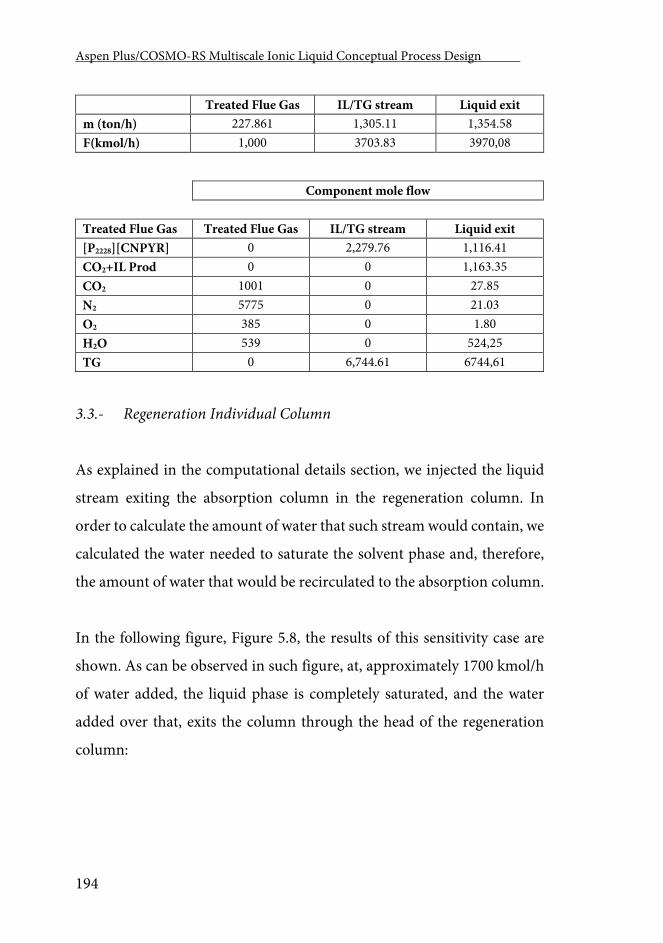
Aspen Plus/COSMO-RS Multiscale Ionic Liquid Conceptual Process Design .
194
Treated Flue Gas IL/TG stream Liquid exit m (ton/h) 227.861 1,305.11 1,354.58 F(kmol/h) 1,000 3703.83 3970,08
Component mole flow Treated Flue Gas Treated Flue Gas IL/TG stream Liquid exit [P2228][CNPYR] 0 2,279.76 1,116.41 CO2+IL Prod 0 0 1,163.35 CO2 1001 0 27.85 N2 5775 0 21.03 O2 385 0 1.80 H2O 539 0 524,25 TG 0 6,744.61 6744,61
3.3.- Regeneration Individual Column
As explained in the computational details section, we injected the liquid
stream exiting the absorption column in the regeneration column. In
order to calculate the amount of water that such stream would contain, we
calculated the water needed to saturate the solvent phase and, therefore,
the amount of water that would be recirculated to the absorption column.
In the following figure, Figure 5.8, the results of this sensitivity case are
shown. As can be observed in such figure, at, approximately 1700 kmol/h
of water added, the liquid phase is completely saturated, and the water
added over that, exits the column through the head of the regeneration
column:
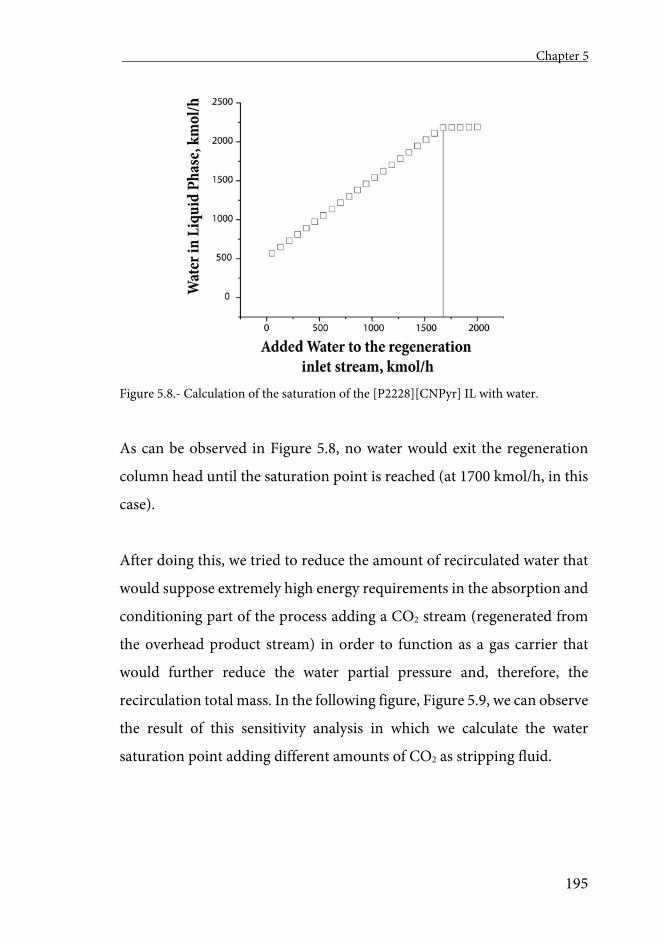
Chapter 5
195
Figure 5.8.- Calculation of the saturation of the [P2228][CNPyr] IL with water.
As can be observed in Figure 5.8, no water would exit the regeneration
column head until the saturation point is reached (at 1700 kmol/h, in this
case).
After doing this, we tried to reduce the amount of recirculated water that
would suppose extremely high energy requirements in the absorption and
conditioning part of the process adding a CO2 stream (regenerated from
the overhead product stream) in order to function as a gas carrier that
would further reduce the water partial pressure and, therefore, the
recirculation total mass. In the following figure, Figure 5.9, we can observe
the result of this sensitivity analysis in which we calculate the water
saturation point adding different amounts of CO2 as stripping fluid.
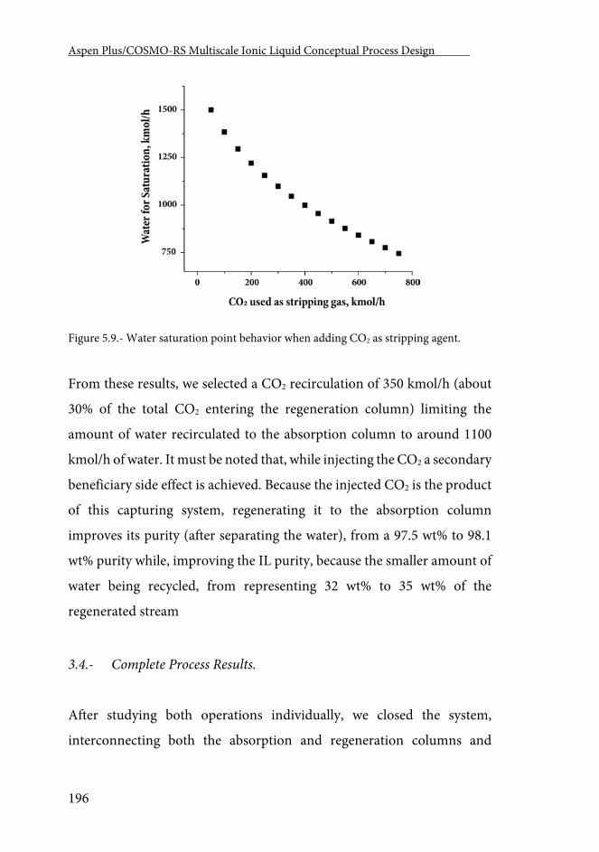
Aspen Plus/COSMO-RS Multiscale Ionic Liquid Conceptual Process Design .
196
Figure 5.9.- Water saturation point behavior when adding CO2 as stripping agent.
From these results, we selected a CO2 recirculation of 350 kmol/h (about
30% of the total CO2 entering the regeneration column) limiting the
amount of water recirculated to the absorption column to around 1100
kmol/h of water. It must be noted that, while injecting the CO2 a secondary
beneficiary side effect is achieved. Because the injected CO2 is the product
of this capturing system, regenerating it to the absorption column
improves its purity (after separating the water), from a 97.5 wt% to 98.1
wt% purity while, improving the IL purity, because the smaller amount of
water being recycled, from representing 32 wt% to 35 wt% of the
regenerated stream
3.4.- Complete Process Results.
After studying both operations individually, we closed the system,
interconnecting both the absorption and regeneration columns and
Chapter 5
197
adding all the accessories and side operations as depicted in Figure 5.1.
When connecting the absorption and regeneration operations, the
streams entering the absorption change, First, some water enters the
column from the saturated S-11 stream (as explained in the Regeneration
Individual Operation section), second, because of other components,
recirculated in smaller proportions (physically absorbed CO2, CO2+AHA
product and traces of N2 and O2 that were physically absorbed in the
absorber’s previous loop). Most of these recirculated components do not
generate any effect in the absorption column while water need to be
considered when recalculating the absorption and regeneration columns.
The recirculated water effect in the regeneration section has been already
addressed and the problems it may generate (a very large recirculation
stream) where solved by injecting recirculated CO2 (S-09) to the stripping
column. When this recirculated water enters the absorption column
(through S-03), it acts as a viscosity reducer, lowering the needs of TG.
Lowering the TG composition to 65%. It is interesting how this water
occupies the role of the TG as it represents a 10.75% of the solvent stream
making the combination of TG and water a 75% of the total solvent stream
(the same co-solvent composition we chose when considering the
absorption individual operation). In Table A_12 we present the total mass
and energy balances of the process. As already stated, we need to clearly
state that the results present in Table_A12 would need to be further
optimized when mass production prices of these ILs are available.
Regarding the energy balance, the total energy needed to recover 33.39
tons of CO2 was 48.12 GJ (around 1.44 GJ/ton of captured CO2). When
Aspen Plus/COSMO-RS Multiscale Ionic Liquid Conceptual Process Design .
198
comparing this value to other existing technologies we obtain that the
energy needed for the chemical capture of CO2 by the AHA ILs studied in
this work is, approximately, the same as the raw energy needed for the
physical capture of CO2 using optimized ILs for physical absorption [84].
Additionally, in this other process most of the energy is the electrical needs
of the compression and pumping systems (a very expensive source of
energy) whereas in the present process, most of the energy, 93%, comes
from cooling water (an extremely cheap source of energy). We can
conclude that, even though further optimization must be done, this
process is more efficient than the physical absorption due to, primarily,
the lower working pressures of both the absorption and regeneration
operations. If compared to other more conventional CO2 capture
technologies, the total energy invested in the chemical absorbing process
with AHA ILs was lower than all the other processes found in literature
(4.2 GJ/ton of CO2 of the amine-based system [285], 4.07 GJ/ton in the
aqueous ammonia process [314], 3.2 GJ/ton of the chemical absorption
using the [bmim][Ac] IL [126] or 3.6 GJ/ton of absorbed CO2 using an
AHA-based IL) [324].
Regarding the IL needs of this process and, because of the higher capacity
of the chemical absorbing ILs, the process presented in this work needed
732.75 tons of IL, or 21.9 tons of IL per ton of capture CO2, versus the 224.5
needed when using physical absorption. As explained before in the
previous work where we analyzed the physical absorption of CO2 [84], this
cost must be considered as part of the capital cost of the process because
the IL is completely regenerated in the stripping column.
Chapter 5
199
4.- Concluding Remarks
The process simulations with rigorous Rate-based and adiabatic modes of
operation indicated that the CO2 chemical absorption operation using
AHA ILs in a commercial packing column shows almost no mass transfer
limitations due to the high working temperatures in which the absorption
operation must work due to the exothermic character of the chemical
reaction. However, from the results summarized in the absorption
individual operation section, we can conclude that the addition of
tetraglyme (TG) as a co-solvent has a beneficial effect in the IL utilization
factor increasing it by almost a 50% factor when using a solvent phase
containing TG up to a 75 mole%.
When attending to the regeneration operation, we observed that the
presence of water may cause extremely high operating costs due to a very
large recirculation stream. We solved this issue by adding CO2 (extracted
from the product stream) that we injected pressurized to the stripping
column to act as a gas carrier. We demonstrated the effect of such addition
while not affecting the regenerated CO2 purity and improving the
regenerated IL composition.
After closing the system, we analyzed the effect of the water recirculated
from the stripping column into the absorption column. We determined
that the water has a homologue effect in the absorption operation to the
TG lowering the TG needed from a 75 mole% to a 65% while the additional
water represented 10.75 mole% of the solvent phase.
Aspen Plus/COSMO-RS Multiscale Ionic Liquid Conceptual Process Design .
200
Finally, we offered preliminary mass and energy balance results of the
complete process. Form such results we can conclude that the CO2 capture
by chemical absorption using AHA ILs is a very promising technology
lowering the energy need to level better that the best technology available
in literature while reducing the use of solvent to only a 10% of such
technology.
As a conclusion, we must say that further re-optimization of this process
should be done after obtaining realistic scaled-up AHA IL prices but,
according to the results presented in this work, the chemical post-
combustion CO2 capture by chemical absorption using AHA Ils is a very
promising technology that may be more efficient both in terms of energy
and solvent consumption than any other technologies presented to the
date. Additionally, the present work demonstrates the ability of the
applied multiescale methodology to consider, simultaneously, very
complex phenomena, such as mass transfer kinetics, chemical equilibrium
and the equilibrium between phases.
Conclusiones -----------------------------------
Conclusions

Conclusiones.
203
Conclusiones y recomendaciones futuras
En el trabajo desarrollado en la presente tesis doctoral se han estudiado
con profundidad dos procesos para los cuales se han propuesto los
líquidos iónicos como disolventes alternativos a los compuestos orgánicos
convencionales. En los tres primeros capítulos se ha estudiado el proceso
de extracción de compuestos aromáticos de naftas con alto contenido en
compuestos alifáticos mientras que en los dos últimos se ha estudiado el
proceso de captura de CO2 de postcombustión.
***
En el primer capítulo, se demostró la capacidad de las simulaciones de
procesos basadas en la metodología multiescala desarrollada con
anterioridad en nuestro grupo de investigación (basadas, pues, en
métodos de predicción de propiedades de tipo COSMO) para tratar, con
confianza, complejas mezclas multicomponente de hidrocarburos y
líquidos iónicos. Se demuestra, a su vez, la bondad de esta metodología
para simular con precisión operaciones unitarias con consistencia
matemática.
Con respecto a las operaciones unitarias analizadas en este capítulo, se
demostró la necesidad de realizar diseños de proceso más complejos de los
realizados en bibliografía. Se concluye que, teniendo en cuenta de forma
simultánea estas operaciones un hipotético líquido iónico [mmim][NTf2]
obtendría el mejor comportamiento combinando las operaciones de
Aspen Plus/COSMO-RS Multiscale Ionic Liquid Conceptual Process Design .
204
extracción y de regeneración del disolvente. Se demuestra, también, los
beneficios combinados de la utilización de mezclas de líquidos iónicos en
este proceso.
En el segundo capítulo, se demuestra la capacidad de las simulaciones de
procesos basadas en COSMO para discriminar entre diferentes
alternativas de proceso mediante la realización de estimaciones razonables
de costes de capital y operativos. Se estudiaron dos procesos de los
generalmente propuestos en bibliografía y se propuso un nuevo proceso
que disminuyó notablemente el consumo tanto de químicos como
energético del proceso.
En el tercer capítulo, se evalúa el comportamiento del simulador de
procesos utilizando COSMOSAC y el modelo termodinámico clásico
NRTL, regresionado a partir de datos experimentales líquido-vapor y
líquido-líquido y se demuestra la coherencia de las predicciones realizadas
con la metodología multiescala. Además, se estudió el comportamiento
del simulador al modelar complejas operaciones integradas. Se muestra la
posibilidad de utilizar los procesos combinados de destilación extractiva
para la extracción de naftas con muy bajo contenido en aromáticos (un
10%).
***
En los capítulos 4 y 5 se aborda el proceso de captura de CO2. En el cuarto
capítulo se demuestra el poder la herramienta integrada de simulación
molecular y de proceso para el diseño de operaciones unitarias de ILs y de
Conclusiones.
205
procesos complejos con elevado control cinético. Se añade dicho control
cinético de transferencia de masa de la operación de absorción de CO2 al
conjunto de criterios de selección de los ILs y se demuestra su elevada
importancia en las operaciones gas-líquido en las que los ILs están siendo
propuestos como alternativa a los compuestos orgánicos volátiles. Se
demuestra la capacidad de la metodología para simular columnas de
separación comerciales asistiendo en el diseño conceptual y los primeros
pasos de la ingeniería básica de procesos que involucran ILs. Se demuestra
que el proceso de captura de CO2 por absorción física tiene un menor
consumo energético que otros procesos de absorción propuestos en
bibliografía si bien la necesidad de trabajar a altas presiones supone un
elevado coste eléctrico en el sistema de compresión.
Por último, en el capítulo 5, se simula, por primera vez utilizando la
metodología multiescala, un proceso con reacción química; la captura de
CO2 mediante líquidos iónicos de aniones heterocíclicos apróticos (AHA).
En este capítulo, se demuestra la capacidad de esta metodología para tener
en cuenta, de forma simultánea, fenómenos muy complejos, como la
cinética de la transferencia de materia, el equilibrio químico y el equilibrio
entre fases. En este capítulo se demuestra la alta competitividad del
proceso propuesto comparándolo con otros procesos de captura de CO2.
Sus menores consumos y costes energéticos y sus menores consumos de
químicos hacen de esta alternativa, una prometedora tecnología para la
captura de CO2 de postcombustión proveniente de plantas térmicas de
carbón.
***
Aspen Plus/COSMO-RS Multiscale Ionic Liquid Conceptual Process Design .
206
Durante la presente tesis, se amplió, desarrolló y aplicó la metodología
multiescala al estudio de diferentes aplicaciones para las cuales los ILs han
sido ampliamente propuestos en bibliografía. A tenor de los resultados
aquí mostrados, se proponen las siguientes recomendaciones futuras.
1. Se ha de continuar profundizando en el estudio de los líquidos
iónicos como sustituyentes verdes de los compuestos orgánicos volátiles
en diferentes aplicaciones. En este sentido, se debe intentar, de forma
paralela y como se ha venido haciendo hasta ahora, ampliar y validar el
uso de la herramienta multiescala a procesos más complejos.
2. Se ha de continuar colaborando con grupos de investigación de
carácter experimentalista para asistirles con los conocimientos
acumulados en el grupo sobre el escalado y el análisis de viabilidad de los
procesos que estudian.
3. Se ha de explorar la aplicación de la metodología multiescala a
otros procesos en los que estén involucrados compuestos cuyo
comportamiento sea difícil de obtener, difícil de aislar o caro de obtener
experimentalmente.
Conclusions.
207
Conclusions and future recommendations.
In the work developed in the present doctoral thesis two processes have
been studied in depth for which ionic liquids have been proposed as
alternative solvents to conventional organic compounds. In the first three
chapters, the process of extracting aromatic compounds from naphtha
with high aliphatic content has been studied, while in the last two chapters
the post-combustion CO2 capture processes both by physical end chemical
absorption have been studied.
***
In the first chapter, the ability of the process simulations based on the
multiscale methodology developed previously in our research group
(based, therefore, on COSMO-type prediction methods) to deal, with
confidence, with complex multicomponent mixtures of hydrocarbons and
ionic liquids was demonstrated. The ability of this methodology to
accurately simulate unit operations with mathematical consistency was
also demonstrated.
With respect to the unit operations analyzed in this chapter, the need
design more complex processes than those present in the literature was
demonstrated. It is concluded that, considering simultaneously these
208
operations a hypothetical [mmim][NTf2] ionic liquid would obtain the
best behavior combining both the liquid-liquid extraction and the solvent
regeneration operations. It is also demonstrated the combined benefits of
using ionic liquid mixtures in this process.
In the second chapter, we demonstrate the ability of the COSMO-based
process simulations to discriminate between different process alternatives
by making reasonable estimates of capital and operational costs. Two
processes generally proposed in bibliography were studied and a new
process was proposed markedly lowering the consumption of both solvent
and energy.
In the third chapter, the behavior of the process simulator is evaluated
using COSMOSAC and the classical thermodynamic NRTL model,
regressed from vapor-liquid and liquid-liquid experimental data and the
coherence of the predictions made with the multiscale methodology is
demonstrated. In addition, the behavior of the simulator was studied when
modeling complex integrated operations. We showed the possibility of
using combined extractive distillation processes for the extraction of
naphtha with very low aromatic content (10%).
***
Conclusions.
209
Chapters 4 and 5 discuss the CO2 capture process both via physical and
chemical absorption. The fourth chapter demonstrates the power of the
integrated molecular and process simulation tool to design of unit
operations of ILs and complex processes with high mass transfer kinetic
control. This kinetic mass transfer control of the CO2 absorption
operation is added to the selection criteria of the ILs and its high
importance is demonstrated in the gas-liquid operations in which the ILs
are being proposed as an alternative to the organic volatile compounds.
The ability of the methodology to simulate commercial separation
columns is demonstrated by assisting in the conceptual design and the first
steps of the basic engineering of process where ILs are involved. It is shown
that the CO2 capturing process by physical absorption has lower energy
consumptions than other absorption processes proposed in literature,
although the need to work at high pressures supposes a high electrical cost
in the compression system.
Finally, in Chapter 5, a process with chemical reaction is simulated, for the
first time, using the multi-scale methodology; the post-combustion CO2
capture process by aprotic heterocyclic anion (AHA) ionic liquids. In this
chapter, we demonstrate the ability of this methodology to consider,
simultaneously, very complex phenomena, such as the mass transfer
kinetics, the chemical equilibrium and the equilibrium between phases.
This chapter demonstrates the high competitiveness of the proposed
210
process by comparing it with other CO2 capture processes proposed in
literature. Its lower energy consumption and costs and its lower
consumption of solvent make this alternative a promising technology for
the capture of post-combustion CO2 produced in coal-fired power plants.
***
During this thesis, the multiscale methodology was expanded, developed
and applied to the study of different applications for which ILs have been
widely proposed in bibliography. Based on the results shown here, the
following future recommendations are proposed.
1. Continue deepening in the study of ionic liquids as alternative
green solvents of volatile organic compounds in different applications. In
this sense, we should try, in parallel, to expand and validate the use of the
multi-scale tool to more complex processes.
2. We must continue to collaborate with experimentalist research
groups to assist them with the knowledge accumulated in the group on the
scaling-up and feasibility analysis of the processes they study.

Conclusions.
211
3. Apply the multi-scale methodology to other processes involving
compounds whose behavior is difficult to obtain, difficult to isolate or
expensive to obtain experimentally.


Appendices -----------------------------------

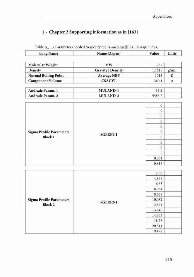
Appendices.
215
1.- Chapter 2 Supporting information as in [163]
Table A_ 1.- Parameters needed to specify the [4-mebupy][BF4] in Aspen Plus.
Long Name Name (Aspen) Value Units
Molecular Weight MW 237 Density Gravity | Density 1.1615 g/mL Normal Boiling Point Average NBP 1013 K Component Volume CSACVL 360.1 Å
Andrade Param. 1 MULAND-1 -13.4 Andrade Param. 2 MULAND-2 5583.2
Sigma Profile Parameters Block 1 SGPRF1-1
0 0 0 0 0 0 0 0 0 0
0.061 0.813
Sigma Profile Parameters Block 2 SGPRF2-1
2.35 4.946
6.63 8.084 8.668
10.082 12.844 13.845 14.853
18.76 20.811 19.128
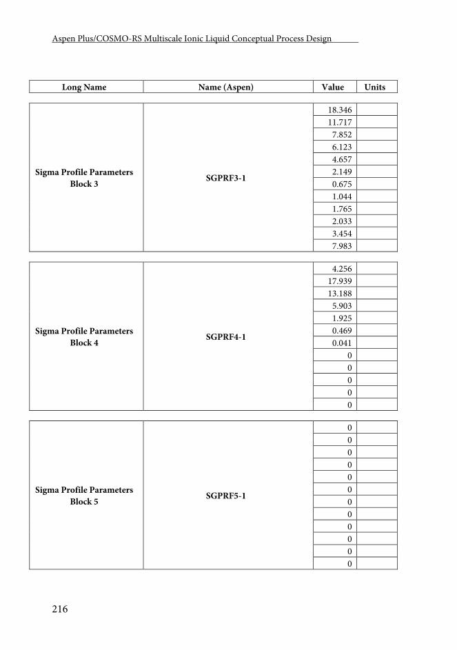
Aspen Plus/COSMO-RS Multiscale Ionic Liquid Conceptual Process Design .
216
Long Name Name (Aspen) Value Units
Sigma Profile Parameters Block 3 SGPRF3-1
18.346 11.717
7.852 6.123 4.657 2.149 0.675 1.044 1.765 2.033 3.454 7.983
Sigma Profile Parameters Block 4 SGPRF4-1
4.256 17.939 13.188
5.903 1.925 0.469 0.041
0 0 0 0 0
Sigma Profile Parameters Block 5 SGPRF5-1
0 0 0 0 0 0 0 0 0 0 0 0
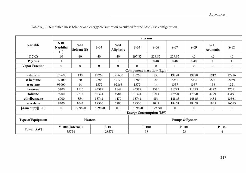
Appendices.
217
Table A_ 2.- Simplified mass balance and energy consumption calculated for the Base Case configuration.
Variable
Streams S-01
Naphtha (F)
S-02 Solvent (S) S-03 S-04
Aliphatic S-05 S-06 S-07 S-09 S-11 Aromatic S-12
T (C) 40 40 40 40 197.85 229.85 229.85 40 40 40 P (atm) 1 1 1 1 1 0.48 0.48 0.48 1 1
Vapor Fraction 0 0 0 0 0 0 1 0 0 0 Component mass flow (kg/h)
n-hexane 129600 130 19265 127680 19265 130 19128 19128 1912 17216 n-heptane 47400 20 2283 47172 2283 20 2266 2266 227 2039 n-octane 93000 14 1372 92863 1372 14 1357 1357 136 1221 benzene 5400 1515 43317 1147 43317 1515 41723 41723 4172 37551 toluene 9900 2214 50321 4984 50321 2214 47990 47990 4799 43191
ethylbenzene 6000 854 15744 4470 15744 854 14845 14845 1484 13361 m-xylene 8700 1047 19560 6800 19560 1047 18458 18458 1845 16613
[4-mebupy][BF4] 0 1559890 1559890 0.6 1559890 1559890 0 0 0 0 Energy Consumption (kW)
Type of Equipment Heaters Pumps & Ejector
Power (kW) V-100 (Internal) E-101 P-100 P-101 P-102
35724 -28579 18 23 4
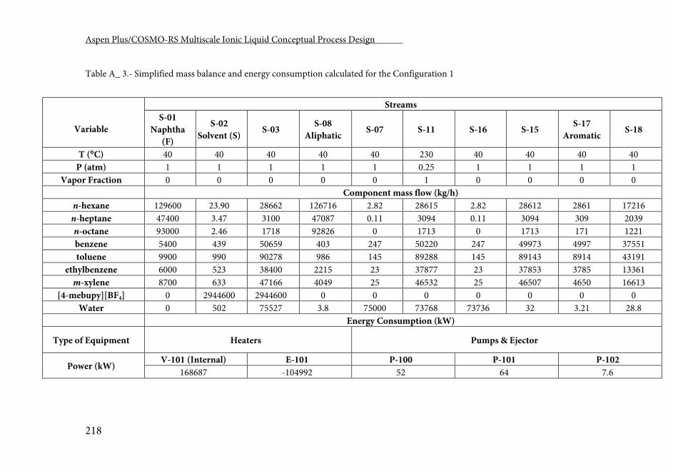
Aspen Plus/COSMO-RS Multiscale Ionic Liquid Conceptual Process Design .
218
Table A_ 3.- Simplified mass balance and energy consumption calculated for the Configuration 1
Variable
Streams S-01
Naphtha (F)
S-02 Solvent (S) S-03 S-08
Aliphatic S-07 S-11 S-16 S-15 S-17 Aromatic S-18
T (C) 40 40 40 40 40 230 40 40 40 40 P (atm) 1 1 1 1 1 0.25 1 1 1 1
Vapor Fraction 0 0 0 0 0 1 0 0 0 0 Component mass flow (kg/h)
n-hexane 129600 23.90 28662 126716 2.82 28615 2.82 28612 2861 17216 n-heptane 47400 3.47 3100 47087 0.11 3094 0.11 3094 309 2039 n-octane 93000 2.46 1718 92826 0 1713 0 1713 171 1221 benzene 5400 439 50659 403 247 50220 247 49973 4997 37551 toluene 9900 990 90278 986 145 89288 145 89143 8914 43191
ethylbenzene 6000 523 38400 2215 23 37877 23 37853 3785 13361 m-xylene 8700 633 47166 4049 25 46532 25 46507 4650 16613
[4-mebupy][BF4] 0 2944600 2944600 0 0 0 0 0 0 0 Water 0 502 75527 3.8 75000 73768 73736 32 3.21 28.8
Energy Consumption (kW)
Type of Equipment Heaters Pumps & Ejector
Power (kW) V-101 (Internal) E-101 P-100 P-101 P-102
168687 -104992 52 64 7.6
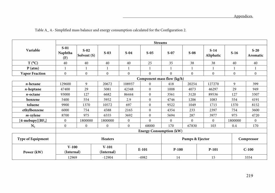
Appendices.
219
Table A_ 4.- Simplified mass balance and energy consumption calculated for the Configuration 2.
Variable
Streams S-01
Naphtha (F)
S-02 Solvent (S) S-03 S-04 S-05 S-07 S-08 S-14
Aliphatic S-16 S-20 Aromatic
T (C) 40 40 40 40 25 35 38 38 40 40 P (atm) 1 1 1 1 1 1 1 1 1 1
Vapor Fraction 0 0 0 0 0 0 0 0 0 0 Component mass flow (kg/h)
n-hexane 129600 9 20672 108937 0 418 20254 127270 9 399 n-heptane 47400 29 5081 42348 0 1008 4073 46297 29 949 n-octane 93000 127 6682 86444 0 3561 3120 89536 127 3307 benzene 5400 554 5952 2.9 0 4746 1206 1083 554 4191 toluene 9900 1370 10572 697 0 9522 1049 1715 1370 8152
ethylbenzene 6000 754 4588 2165 0 4354 233 2397 754 3600 m-xylene 8700 975 6555 3692 0 5694 287 3977 975 4720
[4-mebupy][BF4] 0 1800000 1800000 0 0 0 0 0 1800000 0 N2 0 0 0 0 68000 170 67830 103 0.4 170
Energy Consumption (kW)
Type of Equipment Heaters Pumps & Ejector Compressor
Power (kW) V-100
(Internal) V-101
(Internal) E-101 P-100 P-101 C-100
12969 -12904 -4982 14 15 3354
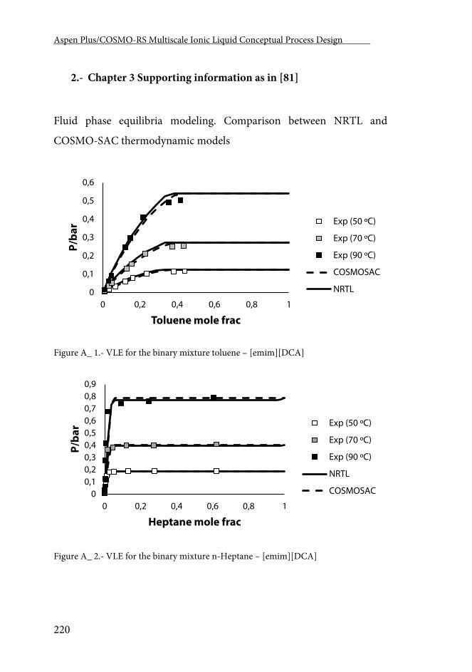
Aspen Plus/COSMO-RS Multiscale Ionic Liquid Conceptual Process Design .
220
2.- Chapter 3 Supporting information as in [81]
Fluid phase equilibria modeling. Comparison between NRTL and
COSMO-SAC thermodynamic models
Figure A_ 1.- VLE for the binary mixture toluene – [emim][DCA]
Figure A_ 2.- VLE for the binary mixture n-Heptane – [emim][DCA]
0
0,1
0,2
0,3
0,4
0,5
0,6
0 0,2 0,4 0,6 0,8 1
P/ba
r
Toluene mole frac
Exp (50 ºC)
Exp (70 ºC)
Exp (90 ºC)
COSMOSAC
NRTL
00,10,20,30,40,50,60,70,80,9
0 0,2 0,4 0,6 0,8 1
P/ba
r
Heptane mole frac
Exp (50 ºC)
Exp (70 ºC)
Exp (90 ºC)
NRTL
COSMOSAC
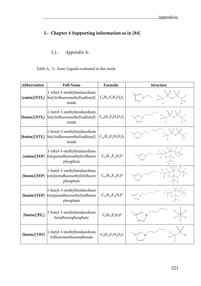
Appendices.
221
3.- Chapter 4 Supporting information as in [84]
3.1.- Appendix A:
Table A_ 5.- Ionic Liquids evaluated in this work.
Abbreviation Full Name Formula Structure
[emim][NTf2] 1-ethyl-3-methylimidazolium bis[(trifluoromethyl)sulfonyl]
imide C8H11F6N3O4S2
[bmim][NTf2] 1-butyl-3-methylimidazolium bis[(trifluoromethyl)sulfonyl]
imide C10H15F6N3O4S2
[hmim][NTf2] 1-hexyl-3-methylimidazolium bis[(trifluoromethyl)sulfonyl]
imide C12H19F6N3O4S2
[emim][FEP] 1-ethyl-3-methylimidazolium tris(pentafluoroethyl)trifluoro
phosphate C12H11F18N2P
[bmim][FEP] 1-butyl-3-methylimidazolium tris(pentafluoroethyl)trifluoro
phosphate C14H15F18N2P
[hmim][FEP] 1-hexyl-3-methylimidazolium tris(pentafluoroethyl)trifluoro
phosphate C16H19F18N2P
[bmim][PF6] 1-butyl-3-methylimidazolium hexafluorophosphate C8H15F6N2P
[bmim][TfO] 1-butyl-3-methylimidazolium trifluoromethanesulfonate C9H15F3N2O3S
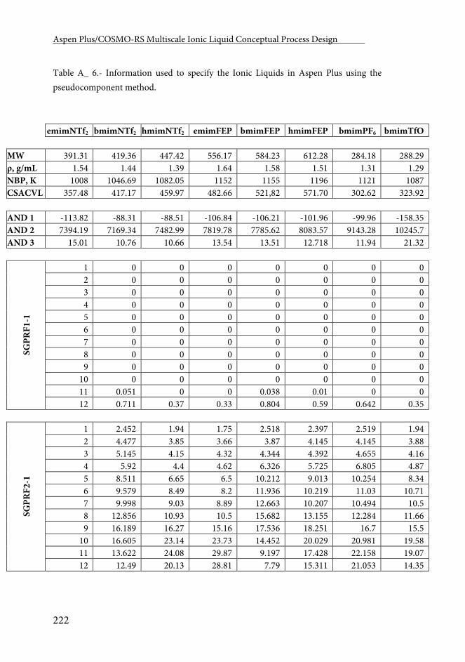
Aspen Plus/COSMO-RS Multiscale Ionic Liquid Conceptual Process Design .
222
Table A_ 6.- Information used to specify the Ionic Liquids in Aspen Plus using the pseudocomponent method.
emimNTf2 bmimNTf2 hmimNTf2 emimFEP bmimFEP hmimFEP bmimPF6 bmimTfO MW 391.31 419.36 447.42 556.17 584.23 612.28 284.18 288.29 ρ, g/mL 1.54 1.44 1.39 1.64 1.58 1.51 1.31 1.29 NBP, K 1008 1046.69 1082.05 1152 1155 1196 1121 1087 CSACVL 357.48 417.17 459.97 482.66 521,82 571.70 302.62 323.92 AND 1 -113.82 -88.31 -88.51 -106.84 -106.21 -101.96 -99.96 -158.35 AND 2 7394.19 7169.34 7482.99 7819.78 7785.62 8083.57 9143.28 10245.7 AND 3 15.01 10.76 10.66 13.54 13.51 12.718 11.94 21.32
SGPR
F1-1
1 0 0 0 0 0 0 0 2 0 0 0 0 0 0 0 3 0 0 0 0 0 0 0 4 0 0 0 0 0 0 0 5 0 0 0 0 0 0 0 6 0 0 0 0 0 0 0 7 0 0 0 0 0 0 0 8 0 0 0 0 0 0 0 9 0 0 0 0 0 0 0 10 0 0 0 0 0 0 0 11 0.051 0 0 0.038 0.01 0 0 12 0.711 0.37 0.33 0.804 0.59 0.642 0.35
SGPR
F2-1
1 2.452 1.94 1.75 2.518 2.397 2.519 1.94 2 4.477 3.85 3.66 3.87 4.145 4.145 3.88 3 5.145 4.15 4.32 4.344 4.392 4.655 4.16 4 5.92 4.4 4.62 6.326 5.725 6.805 4.87 5 8.511 6.65 6.5 10.212 9.013 10.254 8.34 6 9.579 8.49 8.2 11.936 10.219 11.03 10.71 7 9.998 9.03 8.89 12.663 10.207 10.494 10.5 8 12.856 10.93 10.5 15.682 13.155 12.284 11.66 9 16.189 16.27 15.16 17.536 18.251 16.7 15.5 10 16.605 23.14 23.73 14.452 20.029 20.981 19.58 11 13.622 24.08 29.87 9.197 17.428 22.158 19.07 12 12.49 20.13 28.81 7.79 15.311 21.053 14.35
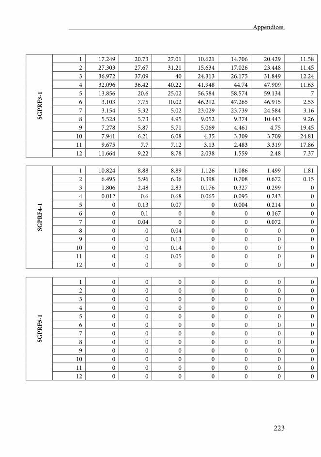
Appendices.
223
SGPR
F3-1
1 17.249 20.73 27.01 10.621 14.706 20.429 11.58 2 27.303 27.67 31.21 15.634 17.026 23.448 11.45 3 36.972 37.09 40 24.313 26.175 31.849 12.24 4 32.096 36.42 40.22 41.948 44.74 47.909 11.63 5 13.856 20.6 25.02 56.584 58.574 59.134 7 6 3.103 7.75 10.02 46.212 47.265 46.915 2.53 7 3.154 5.32 5.02 23.029 23.739 24.584 3.16 8 5.528 5.73 4.95 9.052 9.374 10.443 9.26 9 7.278 5.87 5.71 5.069 4.461 4.75 19.45 10 7.941 6.21 6.08 4.35 3.309 3.709 24.81 11 9.675 7.7 7.12 3.13 2.483 3.319 17.86 12 11.664 9.22 8.78 2.038 1.559 2.48 7.37
SGPR
F4-1
1 10.824 8.88 8.89 1.126 1.086 1.499 1.81 2 6.495 5.96 6.36 0.398 0.708 0.672 0.15 3 1.806 2.48 2.83 0.176 0.327 0.299 0 4 0.012 0.6 0.68 0.065 0.095 0.243 0 5 0 0.13 0.07 0 0.004 0.214 0 6 0 0.1 0 0 0 0.167 0 7 0 0.04 0 0 0 0.072 0 8 0 0 0.04 0 0 0 0 9 0 0 0.13 0 0 0 0 10 0 0 0.14 0 0 0 0 11 0 0 0.05 0 0 0 0 12 0 0 0 0 0 0 0
SGPR
F5-1
1 0 0 0 0 0 0 0 2 0 0 0 0 0 0 0 3 0 0 0 0 0 0 0 4 0 0 0 0 0 0 0 5 0 0 0 0 0 0 0 6 0 0 0 0 0 0 0 7 0 0 0 0 0 0 0 8 0 0 0 0 0 0 0 9 0 0 0 0 0 0 0 10 0 0 0 0 0 0 0 11 0 0 0 0 0 0 0 12 0 0 0 0 0 0 0
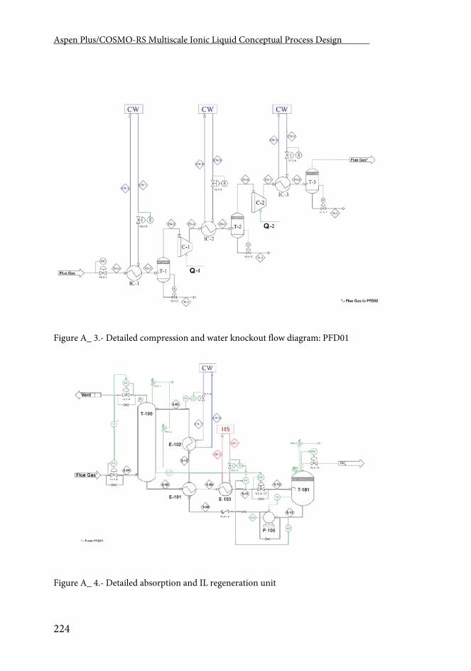
Aspen Plus/COSMO-RS Multiscale Ionic Liquid Conceptual Process Design .
224
Figure A_ 3.- Detailed compression and water knockout flow diagram: PFD01
Figure A_ 4.- Detailed absorption and IL regeneration unit
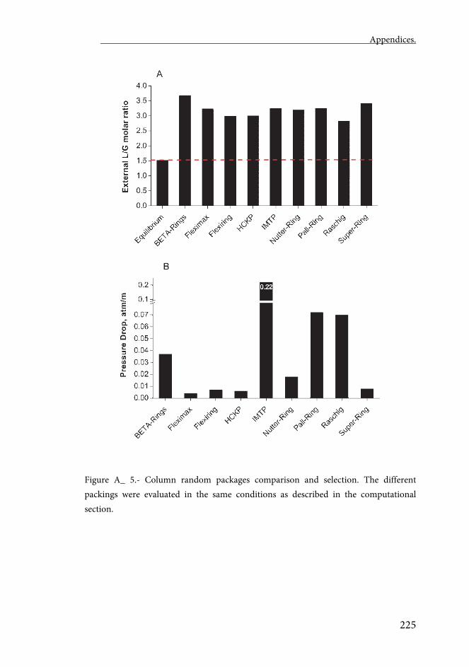
Appendices.
225
Figure A_ 5.- Column random packages comparison and selection. The different packings were evaluated in the same conditions as described in the computational section.
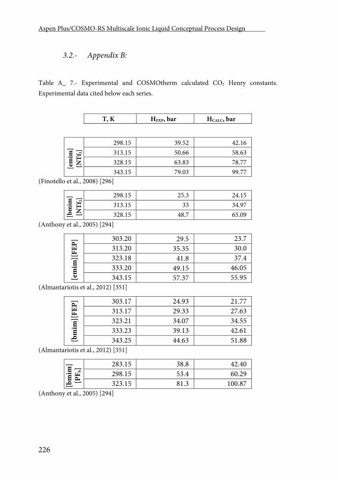
Aspen Plus/COSMO-RS Multiscale Ionic Liquid Conceptual Process Design .
226
3.2.- Appendix B:
Table A_ 7.- Experimental and COSMOtherm calculated CO2 Henry constants. Experimental data cited below each series.
T, K HEXP, bar HCALC, bar
[em
im]
[NTf
2]
298.15 39.52 42.16 313.15 50.66 58.63 328.15 63.83 78.77 343.15 79.03 99.77
(Finotello et al., 2008) [296]
[bm
im]
[NTf
2] 298.15 25.3 24.15
313.15 33 34.97 328.15 48.7 65.09
(Anthony et al., 2005) [294]
[em
im][
FEP]
303.20 29.5 23.7 313.20 35.35 30.0 323.18 41.8 37.4 333.20 49.15 46.05 343.15 57.37 55.95
(Almantariotis et al., 2012) [351]
[bm
im][
FEP]
303.17 24.93 21.77 313.17 29.33 27.63 323.21 34.07 34.55 333.23 39.13 42.61 343.25 44.63 51.88
(Almantariotis et al., 2012) [351]
[bm
im]
[PF 6
] 283.15 38.8 42.40 298.15 53.4 60.29 323.15 81.3 100.87
(Anthony et al., 2005) [294]
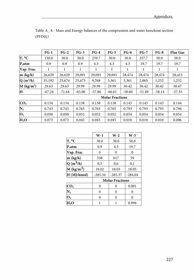
Appendices.
227
Table A_ 8.- Mass and Energy balances of the compression and water knockout section (PFD01)
FG-1 FG-2 FG-3 FG-4 FG-5 FG-6 FG-7 FG-8 Flue Gas T, C 130.0 30.0 30.0 259.7 30.0 30.0 257.7 50.0 50.0 P,atm 0.9 0.9 0.9 4.3 4.3 4.3 19.7 19.7 19.7 Vap. Frac 1 1 1 1 1 1 1 1 1 m (kg/h) 26,629 26,629 29,091 29,091 29,091 28,474 28,474 28,474 28,415 Q (m3/h) 35,192 25,674 25,673 9,768 5,361 5,361 2,065 1,252 1,252 M (kg/m3) 29.63 29.63 29.99 29.99 29.99 30.42 30.42 30.42 30.47 H
-67.24 -71.64 -65.06 -57.86 -66.61 -58.60 -51.49 -58.14 -57.35
Molar Fractions CO2 0.134 0.134 0.138 0.138 0.138 0.143 0.143 0.143 0.144 N2 0.743 0.743 0.765 0.765 0.765 0.793 0.793 0.793 0.796 O2 0.050 0.050 0.052 0.052 0.052 0.054 0.054 0.054 0.054 H2O 0.073 0.073 0.045 0.045 0.045 0.010 0.010 0.010 0.006
W-1 W-2 W-3 T, C 30.0 30.0 50.0 P,atm 0.9 4.3 19.7 Vap. Frac 0 0 0 m (kg/h) 538 617 59 Q (m3/h) 0,5 0,6 0,1 M (kg/m3) 18.02 18.03 18.05 H (MJ/kmol) -285.34 -285.37 -284.04 Molar Fractions CO2 0 0 0.001 N2 0 0 0 O2 0 0 0 H2O 1 1 0.999
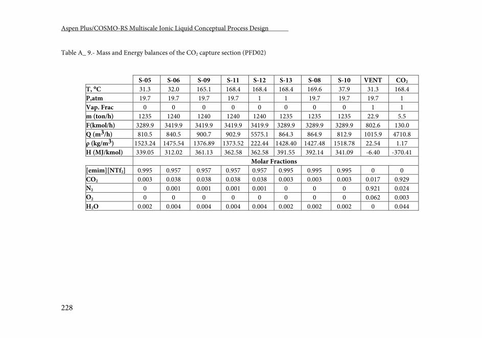
Aspen Plus/COSMO-RS Multiscale Ionic Liquid Conceptual Process Design .
228
Table A_ 9.- Mass and Energy balances of the CO2 capture section (PFD02)
S-05 S-06 S-09 S-11 S-12 S-13 S-08 S-10 VENT CO2 T, C 31.3 32.0 165.1 168.4 168.4 168.4 169.6 37.9 31.3 168.4 P,atm 19.7 19.7 19.7 19.7 1 1 19.7 19.7 19.7 1 Vap. Frac 0 0 0 0 0 0 0 0 1 1 m (ton/h) 1235 1240 1240 1240 1240 1235 1235 1235 22.9 5.5 F(kmol/h) 3289.9 3419.9 3419.9 3419.9 3419.9 3289.9 3289.9 3289.9 802.6 130.0 Q (m3/h) 810.5 840.5 900.7 902.9 5575.1 864.3 864.9 812.9 1015.9 4710.8 ρ (kg/m3) 1523.24 1475.54 1376.89 1373.52 222.44 1428.40 1427.48 1518.78 22.54 1.17 H (MJ/kmol) 339.05 312.02 361.13 362.58 362.58 391.55 392.14 341.09 -6.40 -370.41 Molar Fractions [emim][NTf2] 0.995 0.957 0.957 0.957 0.957 0.995 0.995 0.995 0 0 CO2 0.003 0.038 0.038 0.038 0.038 0.003 0.003 0.003 0.017 0.929 N2 0 0.001 0.001 0.001 0.001 0 0 0 0.921 0.024 O2 0 0 0 0 0 0 0 0 0.062 0.003 H2O 0.002 0.004 0.004 0.004 0.004 0.002 0.002 0.002 0 0.044
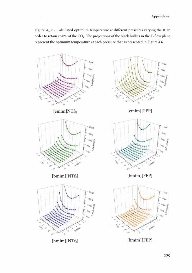
Appendices.
229
Figure A_ 6.- Calculated optimum temperature at different pressures varying the IL in order to retain a 90% of the CO2. The projections of the black bullets in the T-flow plane represent the optimum temperature at each pressure that as presented in Figure 4.6
[emim]NTf2]
[bmim][NTf2]
[hmim][NTf2]
[emim][FEP]
[bmim][FEP]
[hmim][FEP]
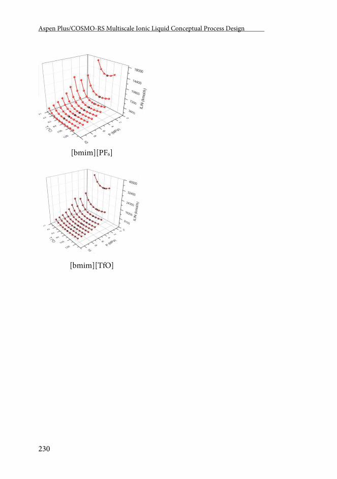
Aspen Plus/COSMO-RS Multiscale Ionic Liquid Conceptual Process Design .
230
[bmim][PF6]
[bmim][TfO]
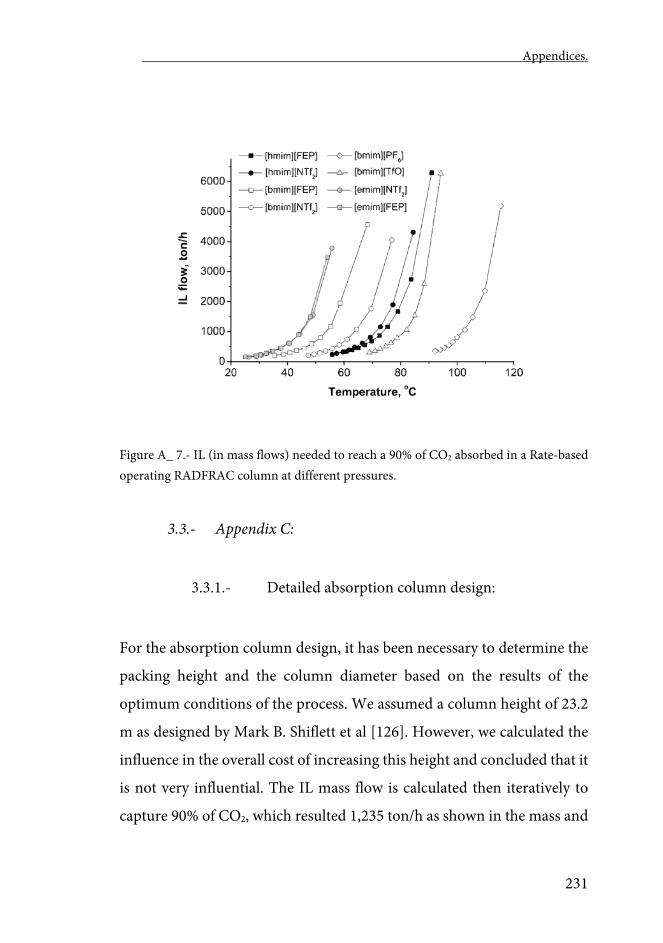
Appendices.
231
Figure A_ 7.- IL (in mass flows) needed to reach a 90% of CO2 absorbed in a Rate-based operating RADFRAC column at different pressures.
3.3.- Appendix C:
3.3.1.- Detailed absorption column design:
For the absorption column design, it has been necessary to determine the
packing height and the column diameter based on the results of the
optimum conditions of the process. We assumed a column height of 23.2
m as designed by Mark B. Shiflett et al [126]. However, we calculated the
influence in the overall cost of increasing this height and concluded that it
is not very influential. The IL mass flow is calculated then iteratively to
capture 90% of CO2, which resulted 1,235 ton/h as shown in the mass and
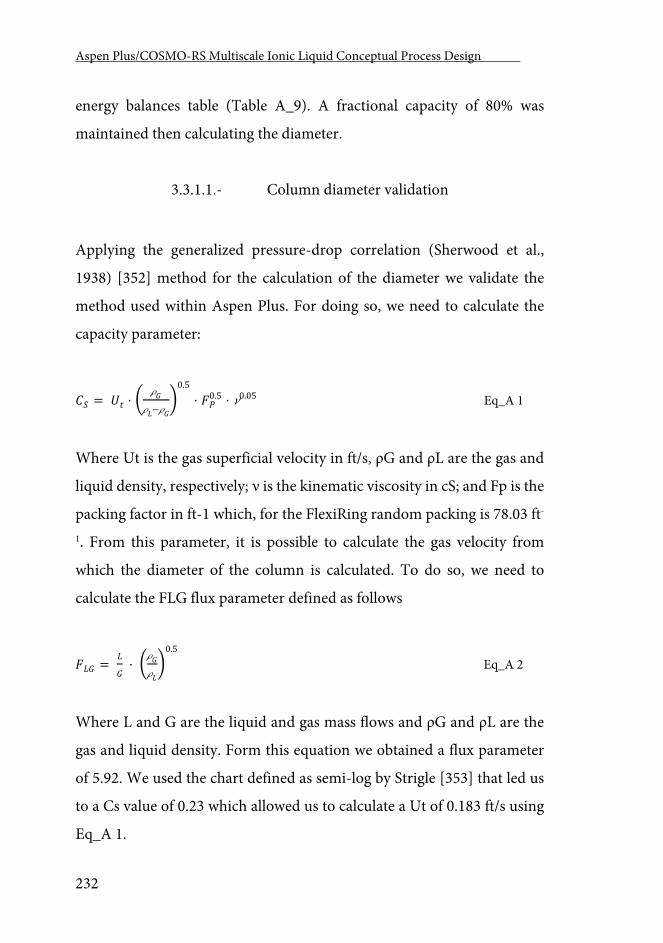
Aspen Plus/COSMO-RS Multiscale Ionic Liquid Conceptual Process Design .
232
energy balances table (Table A_9). A fractional capacity of 80% was
maintained then calculating the diameter.
3.3.1.1.- Column diameter validation
Applying the generalized pressure-drop correlation (Sherwood et al.,
1938) [352] method for the calculation of the diameter we validate the
method used within Aspen Plus. For doing so, we need to calculate the
capacity parameter:
𝐶𝐶𝑅𝑅 = 𝑈𝑈𝑡𝑡 · � 𝐺𝐺
𝐿𝐿−𝐺𝐺�
0.5
· 𝐹𝐹𝑃𝑃0.5 · 0.05 Eq_A 1
Where Ut is the gas superficial velocity in ft/s, ρG and ρL are the gas and
liquid density, respectively; ν is the kinematic viscosity in cS; and Fp is the
packing factor in ft-1 which, for the FlexiRing random packing is 78.03 ft-
1. From this parameter, it is possible to calculate the gas velocity from
which the diameter of the column is calculated. To do so, we need to
calculate the FLG flux parameter defined as follows
𝐹𝐹𝐿𝐿𝐺𝐺 = 𝐿𝐿
𝐺𝐺 · �𝐺𝐺
𝐿𝐿�
0.5
Eq_A 2
Where L and G are the liquid and gas mass flows and ρG and ρL are the
gas and liquid density. Form this equation we obtained a flux parameter
of 5.92. We used the chart defined as semi-log by Strigle [353] that led us
to a Cs value of 0.23 which allowed us to calculate a Ut of 0.183 ft/s using
Eq_A 1.
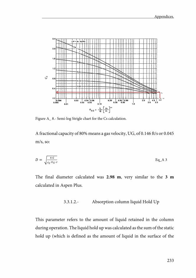
Appendices.
233
Figure A_ 8.- Semi-log Strigle chart for the Cs calculation.
A fractional capacity of 80% means a gas velocity, UG, of 0.146 ft/s or 0.045
m/s, so:
𝑅𝑅 = �4·𝐺𝐺
𝐺𝐺·𝑈𝑈𝐺𝐺· Eq_A 3
The final diameter calculated was 2.98 m, very similar to the 3 m
calculated in Aspen Plus.
3.3.1.2.- Absorption column liquid Hold Up
This parameter refers to the amount of liquid retained in the column
during operation. The liquid hold up was calculated as the sum of the static
hold up (which is defined as the amount of liquid in the surface of the
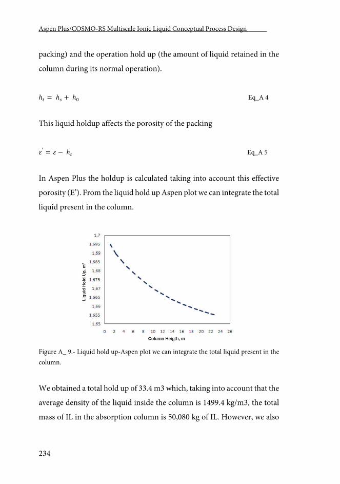
Aspen Plus/COSMO-RS Multiscale Ionic Liquid Conceptual Process Design .
234
packing) and the operation hold up (the amount of liquid retained in the
column during its normal operation).
ℎ𝑡𝑡 = ℎ𝑠𝑠 + ℎ0 Eq_A 4
This liquid holdup affects the porosity of the packing
𝜀𝜀′ = 𝜀𝜀 − ℎ𝑡𝑡 Eq_A 5
In Aspen Plus the holdup is calculated taking into account this effective
porosity (E’). From the liquid hold up Aspen plot we can integrate the total
liquid present in the column.
Figure A_ 9.- Liquid hold up-Aspen plot we can integrate the total liquid present in the column.
We obtained a total hold up of 33.4 m3 which, taking into account that the
average density of the liquid inside the column is 1499.4 kg/m3, the total
mass of IL in the absorption column is 50,080 kg of IL. However, we also
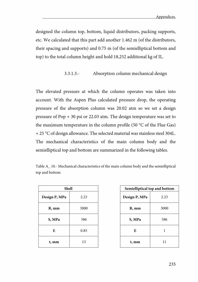
Appendices.
235
designed the column top, bottom, liquid distributors, packing supports,
etc. We calculated that this part add another 1.462 m (of the distributors,
their spacing and supports) and 0.75 m (of the semielliptical bottom and
top) to the total column height and hold 18,252 additional kg of IL.
3.3.1.3.- Absorption column mechanical design
The elevated pressure at which the column operates was taken into
account. With the Aspen Plus calculated pressure drop, the operating
pressure of the absorption column was 20.02 atm so we set a design
pressure of Pop + 30 psi or 22.03 atm. The design temperature was set to
the maximum temperature in the column profile (50 C of the Flue Gas)
+ 25 C of design allowance. The selected material was stainless steel 304L.
The mechanical characteristics of the main column body and the
semielliptical top and bottom are summarized in the following tables.
Table A_ 10.- Mechanical characteristics of the main column body and the semielliptical top and bottom
Shell Semielliptical top and bottom
Design P, MPa 2.23 Design P, MPa 2.23
R, mm 3000 R, mm 3000
S, MPa 586 S, MPa 586
E 0.85 E 1
t, mm 13 t, mm 11
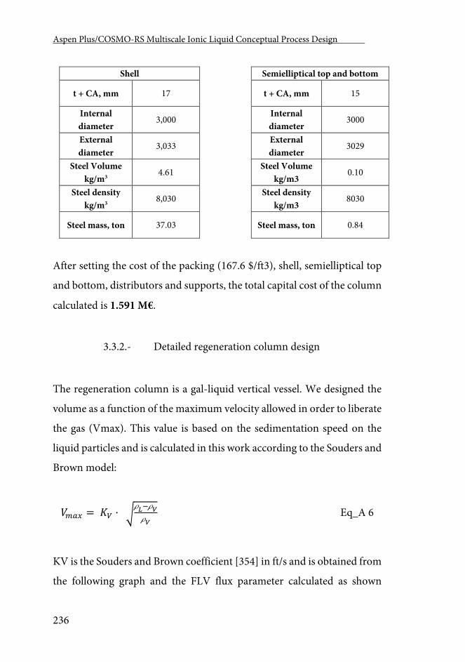
Aspen Plus/COSMO-RS Multiscale Ionic Liquid Conceptual Process Design .
236
Shell Semielliptical top and bottom
t + CA, mm 17 t + CA, mm 15
Internal diameter
3,000 Internal diameter
3000
External diameter
3,033 External diameter
3029
Steel Volume kg/m3
4.61 Steel Volume
kg/m3 0.10
Steel density kg/m3
8,030 Steel density
kg/m3 8030
Steel mass, ton 37.03 Steel mass, ton 0.84
After setting the cost of the packing (167.6 $/ft3), shell, semielliptical top
and bottom, distributors and supports, the total capital cost of the column
calculated is 1.591 M€.
3.3.2.- Detailed regeneration column design
The regeneration column is a gal-liquid vertical vessel. We designed the
volume as a function of the maximum velocity allowed in order to liberate
the gas (Vmax). This value is based on the sedimentation speed on the
liquid particles and is calculated in this work according to the Souders and
Brown model:
𝑉𝑉𝑚𝑚𝑎𝑎𝑥𝑥 = 𝐾𝐾𝑉𝑉 · �𝐿𝐿−𝑉𝑉𝑉𝑉
Eq_A 6
KV is the Souders and Brown coefficient [354] in ft/s and is obtained from
the following graph and the FLV flux parameter calculated as shown
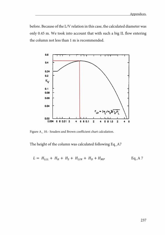
Appendices.
237
before. Because of the L/V relation in this case, the calculated diameter was
only 0.45 m. We took into account that with such a big IL flow entering
the column not less than 1 m is recommended.
Figure A_ 10.- Souders and Brown coefficient chart calculation.
The height of the column was calculated following Eq_A7
𝐿𝐿 = 𝐻𝐻𝐿𝐿𝐿𝐿𝐿𝐿 + 𝐻𝐻𝐻𝐻 + 𝐻𝐻𝑆𝑆 + 𝐻𝐻𝐿𝐿𝐿𝐿𝐿𝐿 + 𝐻𝐻𝐷𝐷 + 𝐻𝐻𝑀𝑀𝑀𝑀 Eq_A 7
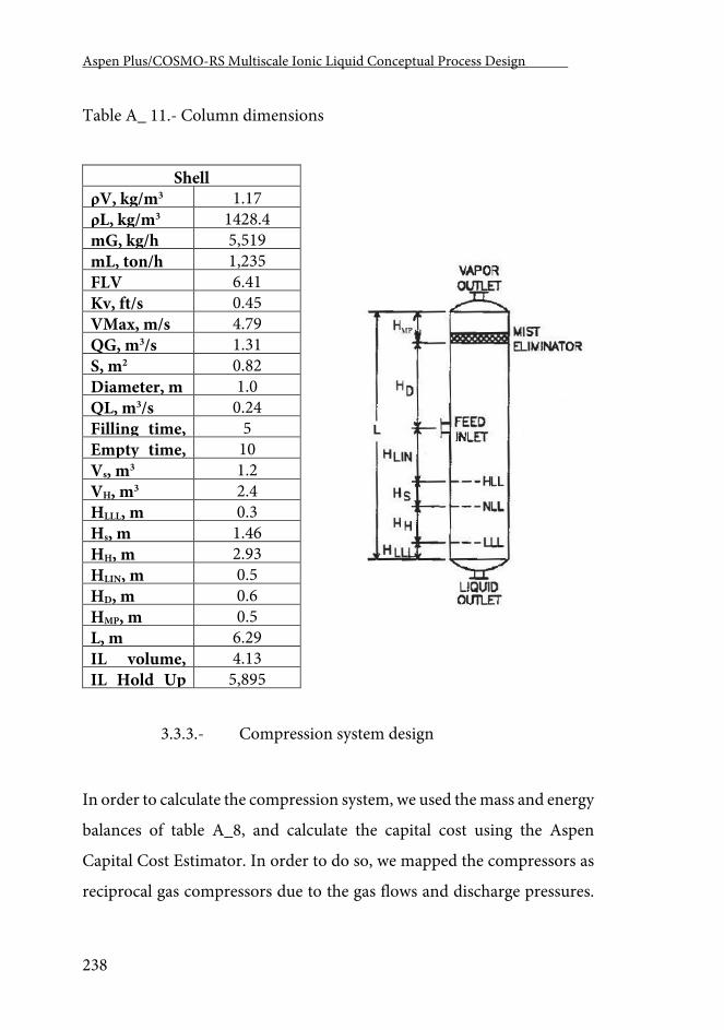
Aspen Plus/COSMO-RS Multiscale Ionic Liquid Conceptual Process Design .
238
Table A_ 11.- Column dimensions
Shell ρV, kg/m3 1.17 ρL, kg/m3 1428.4 mG, kg/h 5,519 mL, ton/h 1,235 FLV 6.41 Kv, ft/s 0.45 VMax, m/s 4.79 QG, m3/s 1.31 S, m2 0.82 Diameter, m 1.0 QL, m3/s 0.24 Filling time,
5 Empty time,
10 Vs, m3 1.2 VH, m3 2.4 HLLL, m 0.3 Hs, m 1.46 HH, m 2.93 HLIN, m 0.5 HD, m 0.6 HMP, m 0.5 L, m 6.29 IL volume,
4.13 IL Hold Up
5,895
3.3.3.- Compression system design
In order to calculate the compression system, we used the mass and energy
balances of table A_8, and calculate the capital cost using the Aspen
Capital Cost Estimator. In order to do so, we mapped the compressors as
reciprocal gas compressors due to the gas flows and discharge pressures.
Appendices.
239
The total capital cost of the compressors was 1.398 M€ for the first one
and 2.205 M€ for the second, leading to a total CAPEX of 3.603 M€. We
need to insist in the preliminary character of this estimations.
3.3.4.- Total IL Holdup.
We considered that the IL present in the system at any time was the sum
of the liquid Hold Up in the absorption column, the liquid in the
accessories of this column and the liquid in the regenerator. We also
considered that 10% of extra IL was circulating at any time.
Total IL Hold Up = ((ILAbs column + ILAbs accessories) + ILRegenerator) x 1.1
Total IL Holdup = ((50,080 + 18,252) + 5,895) x 1.1 = 81,650 kg of [emim][NTf2]
Supposing a preliminary scaled-up price of 20 €/kg this value leads to the
reported 1.633 M€ expenditure in IL and 4.08 M€ if a price of 50 €/kg is
considered
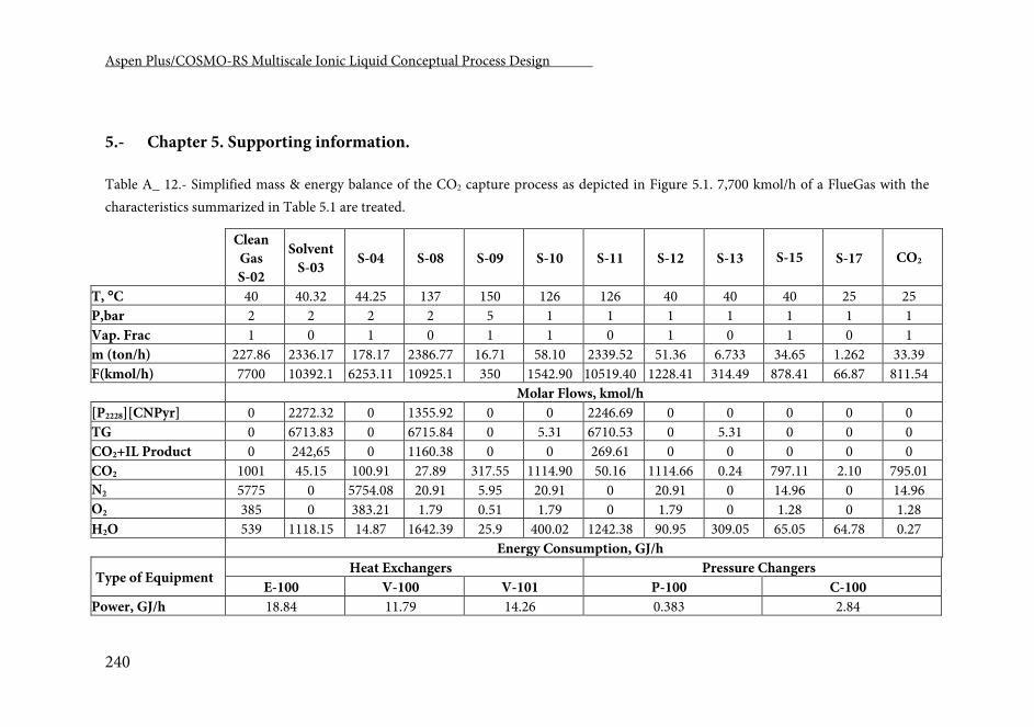
Aspen Plus/COSMO-RS Multiscale Ionic Liquid Conceptual Process Design .
240
5.- Chapter 5. Supporting information.
Table A_ 12.- Simplified mass & energy balance of the CO2 capture process as depicted in Figure 5.1. 7,700 kmol/h of a FlueGas with the characteristics summarized in Table 5.1 are treated.
Clean Gas S-02
Solvent S-03 S-04 S-08 S-09 S-10 S-11 S-12 S-13 S-15 S-17 CO2
T, C 40 40.32 44.25 137 150 126 126 40 40 40 25 25 P,bar 2 2 2 2 5 1 1 1 1 1 1 1 Vap. Frac 1 0 1 0 1 1 0 1 0 1 0 1 m (ton/h) 227.86 2336.17 178.17 2386.77 16.71 58.10 2339.52 51.36 6.733 34.65 1.262 33.39 F(kmol/h) 7700 10392.1 6253.11 10925.1 350 1542.90 10519.40 1228.41 314.49 878.41 66.87 811.54 Molar Flows, kmol/h [P2228][CNPyr] 0 2272.32 0 1355.92 0 0 2246.69 0 0 0 0 0 TG 0 6713.83 0 6715.84 0 5.31 6710.53 0 5.31 0 0 0 CO2+IL Product 0 242,65 0 1160.38 0 0 269.61 0 0 0 0 0 CO2 1001 45.15 100.91 27.89 317.55 1114.90 50.16 1114.66 0.24 797.11 2.10 795.01 N2 5775 0 5754.08 20.91 5.95 20.91 0 20.91 0 14.96 0 14.96 O2 385 0 383.21 1.79 0.51 1.79 0 1.79 0 1.28 0 1.28 H2O 539 1118.15 14.87 1642.39 25.9 400.02 1242.38 90.95 309.05 65.05 64.78 0.27 Energy Consumption, GJ/h
Type of Equipment Heat Exchangers Pressure Changers
E-100 V-100 V-101 P-100 C-100 Power, GJ/h 18.84 11.79 14.26 0.383 2.84
List of Tables.
241
List of Tables
Table 1.1.- Composition of the multi-component (aliphatic + aromatic)
mixtures used in this work for modeling the “real” naphtha feed to the
process to remove aromatic hydrocarbons. ................................................. 37
Table 1.2.- RMSD between experimental and Aspen Plus/Aspen HYSYS
(with COSMOSAC property model) calculated LLE diagrams of some
ternary and quaternary (aliphatic + aromatic + IL(s)) mixtures studied in
the present work. ............................................................................................. 44
Table 1.3.- Results of the Aspen Plus simulations (with COSMOSAC
property model) in the conceptual design of the extraction unit operation
for (aliphatic + aromatic) binary mixtures with ionic liquidsa. Design
specification in the all simulations: to recover 98 % of the aromatic
component in the extract. Feed: 10 wt%-aromatic mixture. Extractor
operating conditions: P = 1 atm, T = 40 C ................................................. 49
Table 1.4.- Results of the Aspen Plus simulations (with COSMOSAC
property model) in the conceptual design of the unit operation to remove
aromatic hydrocarbons from (aromatic + aliphatic) mixtures by
extraction with ionic liquids. Multi-component mixtures 1 and 2 were fed
to the extractor. 12-staged extraction column operating at atmospheric
pressure and T = 40.0 C was used. Design specification: an overall 98.0%
aromatic recovery in the extract. Aliphatics were separated in the raffinate
............................................................................................................................ 53
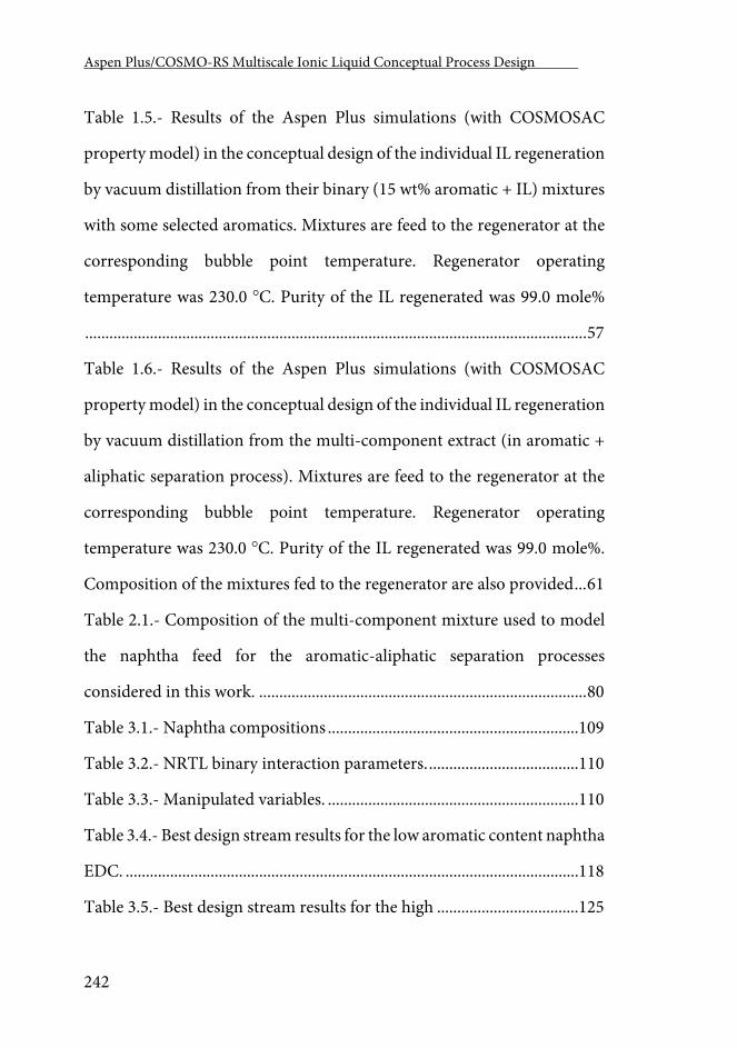
Aspen Plus/COSMO-RS Multiscale Ionic Liquid Conceptual Process Design .
242
Table 1.5.- Results of the Aspen Plus simulations (with COSMOSAC
property model) in the conceptual design of the individual IL regeneration
by vacuum distillation from their binary (15 wt% aromatic + IL) mixtures
with some selected aromatics. Mixtures are feed to the regenerator at the
corresponding bubble point temperature. Regenerator operating
temperature was 230.0 C. Purity of the IL regenerated was 99.0 mole%
............................................................................................................................ 57
Table 1.6.- Results of the Aspen Plus simulations (with COSMOSAC
property model) in the conceptual design of the individual IL regeneration
by vacuum distillation from the multi-component extract (in aromatic +
aliphatic separation process). Mixtures are feed to the regenerator at the
corresponding bubble point temperature. Regenerator operating
temperature was 230.0 C. Purity of the IL regenerated was 99.0 mole%.
Composition of the mixtures fed to the regenerator are also provided ... 61
Table 2.1.- Composition of the multi-component mixture used to model
the naphtha feed for the aromatic-aliphatic separation processes
considered in this work. ................................................................................. 80
Table 3.1.- Naphtha compositions .............................................................. 109
Table 3.2.- NRTL binary interaction parameters. ..................................... 110
Table 3.3.- Manipulated variables. .............................................................. 110
Table 3.4.- Best design stream results for the low aromatic content naphtha
EDC. ................................................................................................................ 118
Table 3.5.- Best design stream results for the high ................................... 125
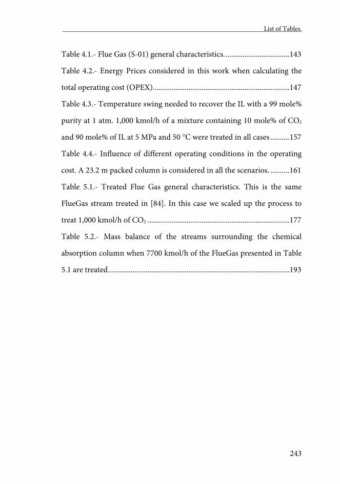
List of Tables.
243
Table 4.1.- Flue Gas (S-01) general characteristics. .................................. 143
Table 4.2.- Energy Prices considered in this work when calculating the
total operating cost (OPEX). ........................................................................ 147
Table 4.3.- Temperature swing needed to recover the IL with a 99 mole%
purity at 1 atm. 1,000 kmol/h of a mixture containing 10 mole% of CO2
and 90 mole% of IL at 5 MPa and 50 C were treated in all cases .......... 157
Table 4.4.- Influence of different operating conditions in the operating
cost. A 23.2 m packed column is considered in all the scenarios. .......... 161
Table 5.1.- Treated Flue Gas general characteristics. This is the same
FlueGas stream treated in [84]. In this case we scaled up the process to
treat 1,000 kmol/h of CO2 ............................................................................ 177
Table 5.2.- Mass balance of the streams surrounding the chemical
absorption column when 7700 kmol/h of the FlueGas presented in Table
5.1 are treated ................................................................................................. 193

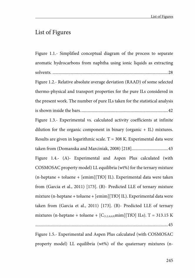
List of Figures
245
List of Figures
Figure 1.1.- Simplified conceptual diagram of the process to separate
aromatic hydrocarbons from naphtha using ionic liquids as extracting
solvents. ............................................................................................................ 28
Figure 1.2.- Relative absolute average deviation (RAAD) of some selected
thermo-physical and transport properties for the pure ILs considered in
the present work. The number of pure ILs taken for the statistical analysis
is shown inside the bars. ................................................................................. 42
Figure 1.3.- Experimental vs. calculated activity coefficients at infinite
dilution for the organic component in binary (organic + IL) mixtures.
Results are given in logarithmic scale. T = 308 K. Experimental data were
taken from (Domanska and Marciniak, 2008) [218] .................................. 43
Figure 1.4.- (A)- Experimental and Aspen Plus calculated (with
COSMOSAC property model) LL equilibria (wt%) for the ternary mixture
(n-heptane + toluene + [emim][TfO] IL). Experimental data were taken
from (Garcia et al., 2011) [173]. (B)- Predicted LLE of ternary mixture
mixture (n-heptane + toluene + [emim][TfO] IL). Experimental data were
taken from (Garcia et al., 2011) [173]. (B)- Predicted LLE of ternary
mixtures (n-heptane + toluene + [C(1,2,4,6,8)mim][TfO] ILs). T = 313.15 K
............................................................................................................................ 45
Figure 1.5.- Experimental and Aspen Plus calculated (with COSMOSAC
property model) LL equilibria (wt%) of the quaternary mixtures (n-
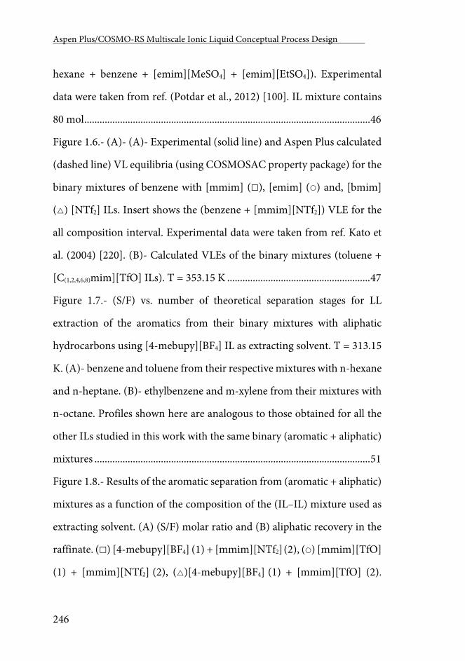
Aspen Plus/COSMO-RS Multiscale Ionic Liquid Conceptual Process Design .
246
hexane + benzene + [emim][MeSO4] + [emim][EtSO4]). Experimental
data were taken from ref. (Potdar et al., 2012) [100]. IL mixture contains
80 mol ................................................................................................................ 46
Figure 1.6.- (A)- (A)- Experimental (solid line) and Aspen Plus calculated
(dashed line) VL equilibria (using COSMOSAC property package) for the
binary mixtures of benzene with [mmim] (), [emim] () and, [bmim]
() [NTf2] ILs. Insert shows the (benzene + [mmim][NTf2]) VLE for the
all composition interval. Experimental data were taken from ref. Kato et
al. (2004) [220]. (B)- Calculated VLEs of the binary mixtures (toluene +
[C(1,2,4,6,8)mim][TfO] ILs). T = 353.15 K ........................................................ 47
Figure 1.7.- (S/F) vs. number of theoretical separation stages for LL
extraction of the aromatics from their binary mixtures with aliphatic
hydrocarbons using [4-mebupy][BF4] IL as extracting solvent. T = 313.15
K. (A)- benzene and toluene from their respective mixtures with n-hexane
and n-heptane. (B)- ethylbenzene and m-xylene from their mixtures with
n-octane. Profiles shown here are analogous to those obtained for all the
other ILs studied in this work with the same binary (aromatic + aliphatic)
mixtures ............................................................................................................ 51
Figure 1.8.- Results of the aromatic separation from (aromatic + aliphatic)
mixtures as a function of the composition of the (IL–IL) mixture used as
extracting solvent. (A) (S/F) molar ratio and (B) aliphatic recovery in the
raffinate. () [4-mebupy][BF4] (1) + [mmim][NTf2] (2), () [mmim][TfO]
(1) + [mmim][NTf2] (2), ()[4-mebupy][BF4] (1) + [mmim][TfO] (2).
List of Figures
247
Multi-component mixture model 1 was fed to the extractor. A 12-staged
extractor was used operating at 40 C and atmospheric pressure. Similar
profiles were obtained for other variables like aliphatic purities and
recoveries. ......................................................................................................... 55
Figure 1.9.- (A)- Operating pressure and (B)- heat duties of the IL
regeneration as a function of the operating temperature for binary mixture
(15 wt% aromatic + [mmim][TfO]). The purity of the IL regenerated is
99.0 mole% ....................................................................................................... 58
Figure 1.10.- Behavior of: (A)- the operating pressure and (B)- the heat
duties of the IL regeneration for binary mixtures (aromatic +
[mmim][TfO]) when an extra 2 wt% load of aliphatic hydrocarbons was
added to the feed (see text for more details). See Table 1.5 for comparison
with binary (aromatic + IL) mixtures. T = 230.0 C. The purity of the IL
regenerated is 99.0 mole% .............................................................................. 60
Figure 1.11.- (A)- Operating pressures and, (B)- heat duties of the
regenerator when IL binary mixtures were used as extracting solvents. ILs
were regenerated from the extracts corresponding to the multi-
component mixture 1. Operating temperature at the regenerator was
230.0 C. ()- ([4-mebupy][BF4](1) + [mmim][NTf2](2)), ()-
([mmim][TfO] (1) + [mmim][NTf2](2)), ()- ([4-mebupy][BF4](1) +
[mmim][TfO](2)) ............................................................................................ 62
Figure 1.12.- Result summary for the: (A)- extracting operation and, (B)-
solvent regeneration for the ILs (and their mixtures) studied in this work.
Aspen Plus/COSMO-RS Multiscale Ionic Liquid Conceptual Process Design .
248
Multi-component mixture 1 was fed to the extractor. IL mixtures (1), (2),
(3) and (4) are, respectively, equi-mass mixtures of ([4-mebupy][BF4] +
[mmim][NTf2]), ([mmim][TfO] + [mmim][NTf2]), ([4-mebupy][BF4] +
[mmim][TfO]) and ([4-mebupy][BF4] + [mmim][NTf2] + [mmim][TfO])
............................................................................................................................ 65
Figure 2.1.- Base Case Configuration: Separation of aromatic and aliphatic
hydrocarbons by extraction. The most commonly proposed flow diagram
is represented ................................................................................................... 77
Figure 2.2.- Configuration 1: Separation of aromatic and aliphatic
hydrocarbons by extraction with ILs using water as co-solvent ............... 78
Figure 2.3.- Configuration 2: Separation of aromatic and aliphatic
hydrocarbons by extraction with ILs using N2 stripping to partially purify
the extract. ........................................................................................................ 79
Figure 2.4.- Purities and recoveries (wt%) of both the raffinate (S-04) and
the aromatic product (S-11) depending on the percentage aromatic
product recycled to T-100 column in Base Case Configuration process
(Figure 2.1). The raffinate purity includes all the aliphatic hydrocarbon
components and the aromatic purity includes all the aromatics
hydrocarbon components .............................................................................. 83
Figure 2.5.- Component Mass Flow profiles for both the individual
aliphatic and aromatic hydrocarbons components in the aromatic product
stream (Figure 2.5 left) and the raffinate stream (Figure 2.5 right), versus
the aromatic stream fraction (wt%) recycled to T-100 column in Base Case
List of Figures
249
Configuration process (Figure 2.1). (1) m-xylene, (2) ethylbenzene, (3)
toluene, (4) benzene, (A) n-octane, (B) n-heptane and (C) n-hexane. In
both the aromatic (left) and aliphatic (right) product streams the
components are sorted the same way. .......................................................... 84
Figure 2.6.- Total energy cost and working pressure of the vacuum
distillation column (V-100) vs the percentage of aromatic product
recirculated to the extraction tower T-100 in Base Case Configuration
process (Figure 2.1). ........................................................................................ 86
Figure 2.7.- Purities and recoveries of both the aliphatic (S-08) and the
aromatic product (S-17) versus the amount of water introduced into the
system in Configuration 1 (Figure 2.2). The raffinate purity includes all
the aliphatic hydrocarbon components and the aromatic purity includes
all the aromatic hydrocarbons (wt%). .......................................................... 87
Figure 2.8.- Component mass flow profiles for both the individual
aliphatic and aromatic hydrocarbons in the aromatic product stream
(Figure 2.8 left) and the aliphatic product stream (Figure 2.8 right) of the
three process configurations analyzed in this work. (1) m-xylene, (2)
ethylbenzene, (3) toluene, (4) benzene, (A) n-octane, (B) n-heptane and
(C) n-hexane. In both the aromatic and aliphatic product streams of all
the three different configurations, the components are sorted the same
way ..................................................................................................................... 88
Figure 2.9.- S/F molar ratio required in Configuration 1 (Figure 2.2) as
function of the amount of water fed to the system. .................................... 90
Aspen Plus/COSMO-RS Multiscale Ionic Liquid Conceptual Process Design .
250
Figure 2.10.- Vacuum distillation pressure and total energy needs in
Configuration 1 (Figure 2.2) as function of the amount of water fed to the
system. ............................................................................................................... 91
Figure 2.11.- Purities and recoveries (wt%) of both the aromatic and
aliphatic product streams as a function of the amount of N2 injected into
the stripper (T-101) in Configuration 2 (Figure 2.3). ................................ 93
Figure 2.12.- Component Mass Flow profiles for both the individual
aliphatic and aromatic hydrocarbons in the aromatic product stream
(Figure 2.12 left) and the raffinate stream (Figure 2.12 right), versus the
amount of N2 injected in the stripper T-101 column in Configuration 2
(Figure 2.3). (1) m-xylene, (2) ethylbenzene, (3) toluene, (4) benzene, (A)
n-octane, (B) n-heptane and (C) n-hexane. In both the aromatic (left) and
aliphatic (right) product streams the components are sorted the same way.
............................................................................................................................ 94
Figure 2.13.- Total energy needs (MW) and S/F molar ratio used of the
different process system configurations studied in this work. .................. 96
Figure 3.1.- Extractive distillation process ................................................. 108
Figure 3.2.- P–x diagram for the mixture [emim][DCA]–toluene.
Experimental data from [242]. .................................................................... 112
Figure 3.3.- P–x diagram for the mixtures [emim][DCA]–n-heptane.
Experimental data from [242]. .................................................................... 113
Figure 3.4.- LLE modeling for the mixtures [emim][DCA]–toluene–n-
heptane at 40 C. Experimental data from [236]. ..................................... 113
List of Figures
251
Figure 3.5.- n-Heptane recovery (wt%) in the distillate stream
(multicomponent separation). 34 theoretical stages, feed in stage 25. RR
between 0.2 and 1. COSMOSAC model ..................................................... 114
Figure 3.6.- n-Heptane mass fraction in the distillate stream
(multicomponent separation). 34 theoretical stages, feed in stage 25. RR
between 0.2 and 1. COSMOSAC model. .................................................... 115
Figure 3.7.- Toluene recovery (kg/h) in the bottom stream
(multicomponent separation). 34 theoretical stages, feed in stage 25. RR
between 0.2 and 1. COSMOSAC model. .................................................... 115
Figure 3.8.- – Reboiler energy consumption (multicomponent
separation). 34 theoretical stages, feed in stage 25. RR between 0.2 and 1.
COSMOSAC model. ..................................................................................... 116
Figure 3.9.- Toluene recovery (kg/h) in the bottom stream
(multicomponent separation). RR = 0.2 and S/F = 2. Number of
theoretical stages between 22 and 34, feed stage between 2 and 33.
COSMOSAC model. ..................................................................................... 117
Figure 3.10.- Influence of distillate flowrate over bottom temperature and
energy consumption (D/F = 0.9; S/F (mass) = 2; number of theoretical
stages = 22; feed stage = 21; RR = 0.2). ....................................................... 120
Figure 3.11.- Influence of distillate flowrate over compositions of both
aromatic and aliphatic stream (D/F = 0.9; S/F (mass) = 2; number of
theoretical stages = 22; feed stage = 21; RR = 0.2). ................................... 120
Aspen Plus/COSMO-RS Multiscale Ionic Liquid Conceptual Process Design .
252
Figure 3.12.- Influence of distillate flowrate over aromatic and aliphatic
recoveries (D/F = 0.9; S/F (mass) = 2; number of theoretical stages = 22;
feed stage = 21; RR = 0.2). ............................................................................ 121
Figure 3.13.- Influence of feed position and number of theoretical stages
over aromatic recoveries (D/F = 0.1; S/F (mass) = 2; RR = 0.2). ............ 122
Figure 3.14.- Influence of distillate flowrate over bottom temperature and
energy consumption (D/F = 0.1; S/F (mass) = 1; number of theoretical
stages = 34; feed stage = 9; RR = 0.2). ......................................................... 123
Figure 3.15.- Influence of distillate flowrate over compositions of both
aromatic and aliphatic stream (D/F = 0.1; S/F (mass) = 1; number of
theoretical stages = 34; feed stage = 9; RR = 0.2). ..................................... 123
Figure 3.16.- Influence of distillate flowrate over aromatic and aliphatic
recoveries (D/F = 0.1; S/F (mass) = 0–1–2; number of theoretical stages =
34; feed stage = 9; RR = 0.2). ........................................................................ 124
Figure 3.17.- Influence of feed position and number of theoretical stages
over aromatic recoveries (D/F = 0.1; S/F (mass) = 0, 1, 2, 3; RR = 0.2). 124
Figure 3.18.- Toluene recovery in the bottom stream. Number of
theoretical stages = 34; RR = 0.2; NRTL and COSMOSAC models. ...... 127
Figure 3.19.- – n-Heptane mass fraction in distillate stream. Number of
theoretical stages = 34; Feed stage = 25; NRTL and COSMOSAC models.
S/F (mass) = 4.5. ............................................................................................ 127
List of Figures
253
Figure 3.20.- n-Heptane mass fraction in distillate stream. Number of
theoretical stages = 34; RR = 0.2; NRTL and COSMOSAC models. S/F
(mass) = 4.5. ................................................................................................... 128
Figure 4.1.- Simplified process design of the CO2 physical absorption
process using ionic liquids as absorbents. Figure A_3 (PFD01) and A_4
(the proper absorption unit, PFD02) of the supporting information
include a complete representation of the modeled process. .................... 142
Figure 4.2.- P-x vapor liquid equilibria for the binary mixtures CO2 + ILs.
The experimental measurements are represented with symbols while the
lines were calculated using COSMO-based process simulations. The alkyl
length of the cation is represented by the inner color of the symbol
[([emim] (■), [bmim] (□) and [hmim] (■)] while the anions are
distinguished by the shape of the symbol [[NTf2] (●), [FEP] (■), [TfO] (▲)
and [PF6] (♦)]. ............................................................................................... 149
Figure 4.3.- Relative Mean Deviations of calculated Density and surface
tension for each IL studied in this work. .................................................... 151
Figure 4.4.- Calculated vs Experimental Diffusion Coefficients of the ILs
used in this work. The alkyl length of the cation is represented by the inner
color of the symbol [([emim] (■), [bmim] (□) and [hmim] (■)] while the
anions are distinguished by the shape of the symbol [([emim] (■), [bmim]
(□) and [hmim] (■)] while the anions are distinguished by the shape of the
symbol [[NTf2] (●), [FEP] (■), [TfO] (▲) and [PF6] (♦)]. ..................... 152
Aspen Plus/COSMO-RS Multiscale Ionic Liquid Conceptual Process Design .
254
Figure 4.5.- Absorbed CO2 as a function of the IL inlet temperature when
the Rad-Frac model that represents the absorber is in equilibrium and
Rate-based operating modes. ....................................................................... 153
Figure 4.6.- Absorbed CO2 in Rate-based operating mode for different ILs.
The alkyl length of the cation is represented by the inner color of the
symbol [([emim] (■), [bmim] (□) and [hmim] (■)] while the anions are
distinguished by the shape of the symbol [NTf2] (●), [FEP] (■), [TfO] (▲)
and [PF6] (♦)]. ................................................................................................ 155
Figure 4.7.- IL needed to reach a 90% of CO2 absorbed in a Rate-based
operating RADFRAC column at different pressures. The inlet temperature
of the IL is in its optimum for each point of the graph as shown in Figure
4.5. .................................................................................................................... 156
Figure 4.8.- Temperature needed to recover the ILs with a 90 mole% purity
at different decompression pressures. The horizontal line represents a
reference maximum operating temperature in order to avoid the thermal
decomposition of the ILs. 1,000 kmol/h of a mixture containing 10 mole%
of CO2 and 90 mole% of IL at 5 MPa and 50 C were treated in all cases.
.......................................................................................................................... 158
Figure 5.1.- Complete process design, proposed for the CO2 capture via
chemical absorption with AHA ILs. ........................................................... 178
Figure 5.2.- Left: Experimental () and calculated (Lines)[P2228][CNPyr] +
CO2 isotherms. Rigth: Experimental () and calculated
(Lines)[P66614][CNPyr] + CO2 isotherms .................................................... 183
List of Figures
255
Figure 5.3.- Experimental vs. calculated physical CO2 solubility in
Tetraglyme at different temperatures and pressures. ............................... 184
Figure 5.4.- Experimental (symbols) vs. calculated (lines) viscosity-to-
temperature dependent data of different [P2228][CNPyr]-TG mixtures 185
Figure 5.5.- Equilibrium (lines) and Rate-based (symbols) column
performance in terms of moles of CO2 captured per mol of IL. The
columns are calculated both in adiabatic (dashed lines, empty symbols)
and isothermal (continuous line, filled symbols) modes of operation. Left
figure corresponds to the [P2228][CNPyr] and right figure to the
[P66614][CNPyr] AHA ILs. ............................................................................. 188
Figure 5.6.- Effect of adding Tetraglyme (TG) in the Equilibrium (lines)
and Rate-based (symbols) column performance in terms of moles of CO2
captured per mol of IL. As in previous studies, columns are calculated in
adiabatic (dashed lines, empty symbols) and isothermal (continuous line,
filled symbols) modes of operation. ............................................................ 190
Figure 5.7.- Left: Effect of adding Tetraglyme in the Adiabatic & Rate-
based column performance in terms of moles of CO2 captured per mol of
IL (line). In this figure, chemically (empty symbols) and physically (filled
symbols) absorbed CO2 are presented individually. Right: Absorber
temperature (dashed line) when adding TG to the fed solvent phase. The
upper raw corresponds to the P2228][CNPyr] AHA IL and the lower raw to
the [P66614][CNPyr] IL. .................................................................................. 192
Aspen Plus/COSMO-RS Multiscale Ionic Liquid Conceptual Process Design .
256
Figure 5.8.- Calculation of the saturation of the [P2228][CNPyr] IL with
water. ............................................................................................................... 195
Figure 5.10.- Water saturation point behavior when adding CO2 as
stripping agent. .............................................................................................. 196

References -----------------------------------

References
259
References
1. Seddon, K.R., Room-temperature ionic liquids: Neoteric solvents for clean catalysis. Kinetics and Catalysis, 1996. 37(5): p. 693-697.
2. Krossing, I., et al., Why are ionic liquids liquid? A simple explanation based on lattice and solvation energies. Journal of the American Chemical Society, 2006. 128(41): p. 13427-13434.
3. Freemantle, M., Designer solvents - Ionic liquids may boost clean technology development. Chemical & Engineering News, 1998. 76(13): p. 32-37.
4. Walden, P., Molecular Weights and Electrical Conductivity of Several Fused Salts. Bulletin of the Russian Academy of Sciences, 1914: p. 405-422.
5. Wilkes, J.S. and M.J. Zaworotko, Air and water stable 1-ethyl-3-methylimidazolium based ionic liquids. Journal of the Chemical Society-Chemical Communications, 1992(13): p. 965-967.
6. Volland, M., et al., Verfahren zur abtrennung von säuren aus chemischen reaktionsgemischen mit hilfe von ionischen flüssigkeiten, in IFI CLAIMS Patent Services. 2002, BASF Aktiengesellschaft: WO2003062251A1.
7. Phillips, G.W., et al., Continuous Process for the Manufacture of 2,5-dihydrofuranes from η,δ-epoxybutanes, in IFI CLAIMS Patent Services. 1991, Eastman Kodak Company: WO1993010111A1.
8. Welton, T., Room-temperature ionic liquids. Solvents for synthesis and catalysis. Chemical Reviews, 1999. 99(8): p. 2071-2083.
9. Gordon, C.M., New developments in catalysis using ionic liquids. Applied Catalysis a-General, 2001. 222(1-2): p. 101-117.
10. Sheldon, R., Catalytic reactions in ionic liquids. Chemical Communications, 2001(23): p. 2399-2407.
11. Liu, J.F., J.A. Jonsson, and G.B. Jiang, Application of ionic liquids in analytical chemistry. Trac-Trends in Analytical Chemistry, 2005. 24(1): p. 20-27.
12. Lee, S.G., Functionalized imidazolium salts for task-specific ionic liquids and their applications. Chemical Communications, 2006(10): p. 1049-1063.
Aspen Plus/COSMO-RS Multiscale Ionic Liquid Conceptual Process Design .
260
13. Pandey, S., Analytical applications of room-temperature ionic liquids: A review of recent efforts. Analytica Chimica Acta, 2006. 556(1): p. 38-45.
14. Zhu, S.D., et al., Dissolution of cellulose with ionic liquids and its application: a mini-review. Green Chemistry, 2006. 8(4): p. 325-327.
15. Greaves, T.L. and C.J. Drummond, Protic ionic liquids: Properties and applications. Chemical Reviews, 2008. 108(1): p. 206-237.
16. Plechkova, N.V. and K.R. Seddon, Applications of ionic liquids in the chemical industry. Chemical Society Reviews, 2008. 37(1): p. 123-150.
17. Lu, J., F. Yan, and J. Texter, Advanced applications of ionic liquids in polymer science. Progress in Polymer Science, 2009. 34(5): p. 431-448.
18. Heintz, A., Recent developments in thermodynamics and thermophysics of non-aqueous mixtures containing ionic liquids. A review. Journal of Chemical Thermodynamics, 2005. 37(6): p. 525-535.
19. Rebelo, L.P.N., et al., On the critical temperature, normal boiling point, and vapor pressure of ionic liquids. Journal of Physical Chemistry B, 2005. 109(13): p. 6040-6043.
20. Trohalaki, S., et al., Quantitative structure-property relationships for melting points and densities of ionic liquids. Energy & Fuels, 2005. 19(1): p. 279-284.
21. MacFarlane, D.R., et al., Ionic liquids based on imidazolium, ammonium and pyrrolidinium salts of the dicyanamide anion. Green Chemistry, 2002. 4(5): p. 444-448.
22. Fredlake, C.P., et al., Thermophysical properties of imidazolium-based ionic liquids. Journal of Chemical and Engineering Data, 2004. 49(4): p. 954-964.
23. Crosthwaite, J.M., et al., Phase transition and decomposition temperatures, heat capacities and viscosities of pyridinium ionic liquids. Journal of Chemical Thermodynamics, 2005. 37(6): p. 559-568.
24. Meindersma, G.W. and A.B. De Haan, Cyano-containing ionic liquids for the extraction of aromatic hydrocarbons from an aromatic/aliphatic mixture. Science China-Chemistry, 2012. 55(8): p. 1488-1499.
References
261
25. Sato, T., G. Masuda, and K. Takagi, Electrochemical properties of novel ionic liquids for electric double layer capacitor applications. Electrochimica Acta, 2004. 49(21): p. 3603-3611.
26. Zhao, F., et al., Electrochemical and bioelectrochemistry properties of room-temperature ionic liquids and carbon composite materials. Analytical Chemistry, 2004. 76(17): p. 4960-4967.
27. Matsumoto, H., H. Sakaebe, and K. Tatsumi, Preparation of room temperature ionic liquids based on aliphatic onium cations and. asymmetric amide anions and their electrochemical properties as a lithium battery electrolyte. Journal of Power Sources, 2005. 146(1-2): p. 45-50.
28. Tsunashima, K. and M. Sugiya, Physical and electrochemical properties of low-viscosity phosphonium ionic liquids as potential electrolytes. Electrochemistry Communications, 2007. 9(9): p. 2353-2358.
29. Pu, Y., N. Jiang, and A.J. Ragauskas, Ionic liquid as a green solvent for lignin. Journal of Wood Chemistry and Technology, 2007. 27(1): p. 23-33.
30. Zhao, H., S.Q. Xia, and P.S. Ma, Use of ionic liquids as 'green' solvents for extractions. Journal of Chemical Technology and Biotechnology, 2005. 80(10): p. 1089-1096.
31. Kubisa, P., Application of ionic liquids as solvents for polymerization processes. Progress in Polymer Science, 2004. 29(1): p. 3-12.
32. Bennett, M.D. and D.J. Leo, Ionic liquids as stable solvents for ionic polymer transducers. Sensors and Actuators a-Physical, 2004. 115(1): p. 79-90.
33. Cull, S.G., et al., Room-temperature ionic liquids as replacements for organic solvents in multiphase bioprocess operations. Biotechnology and Bioengineering, 2000. 69(2): p. 227-233.
34. Saravanamurugan, S., et al., Amine-Functionalized Amino Acid- based Ionic Liquids as Efficient and High- Capacity Absorbents for CO2. Chemsuschem, 2014. 7(3): p. 897-902.
35. Bedia, J., et al., Screening ionic liquids as suitable ammonia absorbents on the basis of thermodynamic and kinetic analysis. Separation and Purification Technology, 2012. 95: p. 188-195.
Aspen Plus/COSMO-RS Multiscale Ionic Liquid Conceptual Process Design .
262
36. Hong, S.Y., et al., Ether-functionalized ionic liquids as highly efficient SO2 absorbents. Energy & Environmental Science, 2011. 4(5): p. 1802-1806.
37. Harper, N.D., et al., Survey of Carbon Dioxide Capture in Phosphonium-Based Ionic Liquids and End-Capped Polyethylene Glycol Using DETA (DETA = Diethylenetriamine) as a Model Absorbent. Industrial & Engineering Chemistry Research, 2011. 50(5): p. 2822-2830.
38. Lee, K.Y., et al., Use of ionic liquids as absorbents to separate SO2 in SO2/O2 in thermochemical processes to produce hydrogen. International Journal of Hydrogen Energy, 2008. 33(21): p. 6031-6036.
39. Wilkes, J.S., A short history of ionic liquids - from molten salts to neoteric solvents. Green Chemistry, 2002. 4(2): p. 73-80.
40. Parshall, G.W., Catalysis in molten salt media. Journal of the American Chemical Society, 1972. 94(25): p. 8716-&.
41. Rogers, R.D. and K.R. Seddon, Ionic Liquids: Industrial Applications to Green Chemistry. Journal of the American Chemical Society, 2003. 125(24): p. 7480-7480.
42. Atkins, M.P., et al., Ionic Liquids: A Map for Industrial Innovation. Report Q001. 2004, Belfast: QUILL.
43. Fadeev, A.G. and M.M. Meagher, Opportunities for ionic liquids in recovery of biofuels. Chemical Communications, 2001(03): p. 295-296.
44. Bosmann, A., et al., Deep desulfurization of diesel fuel by extraction with ionic liquids. Chemical Communications, 2001(23): p. 2494-2495.
45. Ye, C.F., et al., Room-temperature ionic liquids: a novel versatile lubricant. Chemical Communications, 2001(21): p. 2244-2245.
46. Papageorgiou, N., et al., The performance and stability of ambient temperature molten salts for solar cell applications. Journal of the Electrochemical Society, 1996. 143(10): p. 3099-3108.
47. Gratzel, M., Low Cost and Efficient Photovoltaic Conversion by Nanocrystalline Solar Cells Low Cost and Efficient Photovoltaic Conversion by Nanocrystalline Solar Cells. Chemie Ingenieur Technik, 1995. 67(10): p. 1300-1305.
References
263
48. Kubo, W., et al., Quasi-solid-state dye-sensitized solar cells using room temperature molten salts and a low molecular weight gelator. Chemical Communications, 2002(4): p. 374-375.
49. MacFarlane, D.R., et al., Energy applications of ionic liquids. Energy & Environmental Science, 2014. 7(1): p. 232-250.
50. Rao, P.R.V., et al., Potential Applications of Room Temperature Ionic Liquids for Fission Products and Actinide Separation. Separation Science and Technology, 2012. 47(2): p. 204-222.
51. Koch, V.R., C. Nanjundiah, and R.T. Carlin, Hydrophobic ionic liquids, in IFI CLAIMS Patent Services. 1996, Covalent Associates, Inc.: WO1997002252A1.
52. Doyle, M., S.K. Choi, and G. Proulx, High-temperature proton conducting membranes based on perfluorinated ionomer membrane-ionic liquid composites. Journal of the Electrochemical Society, 2000. 147(1): p. 34-37.
53. Fuller, J., A.C. Breda, and R.T. Carlin, Ionic liquid-polymer gel electrolytes. Journal of the Electrochemical Society, 1997. 144(4): p. L67-L70.
54. Swatloski, R.P., et al., Dissolution of cellose with ionic liquids. Journal of the American Chemical Society, 2002. 124(18): p. 4974-4975.
55. Yokozeki, A. and M.B. Shillett, Water Solubility in Ionic Liquids and Application to Absorption Cycles. Industrial & Engineering Chemistry Research, 2010. 49(19): p. 9496-9503.
56. Ruiz, E., et al., Evaluation of ionic liquids as absorbents for ammonia absorption refrigeration cycles using COSMO-based process simulations. Applied Energy, 2014. 123: p. 281-291.
57. Moreno, D., et al., The role of refrigerant-absorbent selection in absorption refrigeration cycles based on ionic liquids: Thermodynamic and process analysis. In Preparation, 2017.
58. Huddleston, J.G., et al., Room temperature ionic liquids as novel media for 'clean' liquid-liquid extraction. Chemical Communications, 1998(16): p. 1765-1766.
59. Visser, A.E., et al., Task-specific ionic liquids for the extraction of metal ions from aqueous solutions. Chemical Communications, 2001(01): p. 135-136.
Aspen Plus/COSMO-RS Multiscale Ionic Liquid Conceptual Process Design .
264
60. Meindersma, G.W., A.J.G. Podt, and A.B. de Haan, Selection of ionic liquids for the extraction of aromatic hydrocarbons from aromatic/aliphatic mixtures. Fuel Processing Technology, 2005. 87(1): p. 59-70.
61. Meindersma, G.W., A. Podt, and A.B. de Haan, Ternary liquid-liquid equilibria for mixtures of an aromatic plus an aliphatic hydrocarbon+4-methyl-N-butylpyridinium tetrafluoroborate. Journal of Chemical and Engineering Data, 2006. 51(5): p. 1814-1819.
62. Meindersma, G.W., A.J.G. Podt, and A.B. de Haan, Ternary liquid-liquid equilibria for mixtures of toluene plus n-heptane plus an ionic liquid. Fluid Phase Equilibria, 2006. 247(1-2): p. 158-168.
63. Domanska, U., A. Pobudkowska, and M. Krolikowski, Separation of aromatic hydrocarbons from alkanes using ammonium ionic liquid C2NTf2 at T=298.15 K. Fluid Phase Equilibria, 2007. 259(2): p. 173-179.
64. Meindersma, G.W. and A.B. de Haan, Conceptual process design for aromatic/aliphatic separation with ionic liquids. Chemical Engineering Research & Design, 2008. 86(7A): p. 745-752.
65. Marciniak, A., Influence of cation and anion structure of the ionic liquid on extraction processes based on activity coefficients at infinite dilution. A review. Fluid Phase Equilibria, 2010. 294(1-2): p. 213-233.
66. Meindersma, G.W., A.R. Hansmeier, and A.B. de Haan, Ionic Liquids for Aromatics Extraction. Present Status and Future Outlook. Industrial & Engineering Chemistry Research, 2010. 49(16): p. 7530-7540.
67. Zhang, Y., et al., Dual Amino-Functionalised Phosphonium Ionic Liquids for CO2 Capture. Chemistry-a European Journal, 2009. 15(12): p. 3003-3011.
68. Brennecke, J.F. and B.E. Gurkan, Ionic Liquids for CO2 Capture and Emission Reduction. Journal of Physical Chemistry Letters, 2010. 1(24): p. 3459-3464.
69. D'Alessandro, D.M., B. Smit, and J.R. Long, Carbon Dioxide Capture: Prospects for New Materials. Angewandte Chemie-International Edition, 2010. 49(35): p. 6058-6082.
70. Giernoth, R., Task-Specific Ionic Liquids. Angewandte Chemie-International Edition, 2010. 49(16): p. 2834-2839.
References
265
71. Gurkan, B.E., et al., Equimolar CO2 Absorption by Anion-Functionalized Ionic Liquids. Journal of the American Chemical Society, 2010. 132(7): p. 2116-2117.
72. Hasib-ur-Rahman, M., M. Siaj, and F. Larachi, Ionic liquids for CO2 capture-Development and progress. Chemical Engineering and Processing, 2010. 49(4): p. 313-322.
73. Karadas, F., M. Atilhan, and S. Aparicio, Review on the Use of Ionic Liquids (ILs) as Alternative Fluids for CO2 Capture and Natural Gas Sweetening. Energy & Fuels, 2010. 24: p. 5817-5828.
74. Wang, C., et al., Tuning the Basicity of Ionic Liquids for Equimolar CO2 Capture. Angewandte Chemie-International Edition, 2011. 50(21): p. 4918-4922.
75. Yu, C.-H., C.-H. Huang, and C.-S. Tan, A Review of CO2 Capture by Absorption and Adsorption. Aerosol and Air Quality Research, 2012. 12(5): p. 745-769.
76. Bonhote, P., et al., Hydrophobic, highly conductive ambient-temperature molten salts. Inorganic Chemistry, 1996. 35(5): p. 1168-1178.
77. de Riva, J., et al., Statistical Refinement and Fitting of Experimental Viscosity-to-Temperature Data in Ionic Liquids. Industrial & Engineering Chemistry Research, 2014. 53(25): p. 10475-10484.
78. Seddon, K.R., A. Stark, and M.J. Torres, Influence of chloride, water, and organic solvents on the physical properties of ionic liquids. Pure and Applied Chemistry, 2000. 72(12): p. 2275-2287.
79. Green, M.D. and T.E. Long, Designing Imidazole-Based Ionic Liquids and Ionic Liquid Monomers for Emerging Technologies. Polymer Reviews, 2009. 49(4): p. 291-314.
80. Ferro, V.R., et al., Conceptual design of unit operations to separate aromatic hydrocarbons from naphtha using ionic liquids. COSMO-based process simulations with multi-component “real” mixture feed. Chemical Engineering Research and Design, 2015. 94: p. 632-647.
81. Diaz, I., et al., Ionic liquids as entrainers for the separation of aromatic-aliphatic hydrocarbon mixtures by extractive distillation. Chemical Engineering Research & Design, 2016. 115: p. 382-393.
Aspen Plus/COSMO-RS Multiscale Ionic Liquid Conceptual Process Design .
266
82. Garcia, S., et al., (Liquid plus liquid) equilibrium for the ternary systems (heptane plus toluene+1-allyl-3-methylimidazolium bis(trifluoromethylsulfonyl)imide) and (heptane plus toluene+1-methyl-3-propylimidazolium bis(trifluoromethylsulfonyl)imide) ionic liquids. Journal of Chemical Thermodynamics, 2011. 43(11): p. 1641-1645.
83. Garcia, S., et al., 1-Alkyl-2,3-dimethylimidazolium Bis(trifluoromethylsulfonyl)imide Ionic Liquids for the Liquid-Liquid Extraction of Toluene from Heptane. Journal of Chemical and Engineering Data, 2011. 56(8): p. 3468-3474.
84. de Riva, J., et al., Ionic liquids for post-combustion CO2 capture by physical absorption: Thermodynamic, kinetic and process analysis. International Journal of Greenhouse Gas Control, 2017. 61: p. 61-70.
85. Seo, S., M.A. DeSilva, and J.F. Brennecke, Physical Properties and CO2 Reaction Pathway of 1-Ethyl-3-Methylimidazolium Ionic Liquids with Aprotic Heterocyclic Anions. Journal of Physical Chemistry B, 2014. 118(51): p. 14870-14879.
86. Fillion, J.J., et al., Phase Transitions, Decomposition Temperatures, Viscosities, and Densities of Phosphonium, Ammonium, and Imidazolium Ionic Liquids with Aprotic Heterocyclic Anions. Journal of Chemical and Engineering Data, 2016. 61(8): p. 2897-2914.
87. Fillion, J.J., J.E. Bennett, and J.F. Brennecke, The Viscosity and Density of Ionic Liquid plus Tetraglyme Mixtures and the Effect of Tetraglyme on CO2 Solubility. Journal of Chemical and Engineering Data, 2017. 62(2): p. 608-622.
88. Olivier-Bourbigou, H. and L. Magna, Ionic liquids: perspectives for organic and catalytic reactions. Journal of Molecular Catalysis a-Chemical, 2002. 182(1): p. 419-437.
89. Chiappe, C. and D. Pieraccini, Ionic liquids: solvent properties and organic reactivity. Journal of Physical Organic Chemistry, 2005. 18(4): p. 275-297.
90. Dzyuba, S.V. and R.A. Bartsch, Influence of structural variations in 1-alkyl(aralkyl)-3-methylimidazolium hexafluorophosphates and bis(trifluorormethyl-sulfonyl)imides on physical properties of the ionic liquids. Chemphyschem, 2002. 3(2): p. 161-166.
References
267
91. Poole, C.F., Chromatographic and spectroscopic methods for the determination of solvent properties of room temperature ionic liquids. Journal of Chromatography A, 2004. 1037(1): p. 49-82.
92. Docherty, K.M. and C.F. Kulpa, Toxicity and antimicrobial activity of imidazolium and pyridinium ionic liquids. Green Chemistry, 2005. 7(4): p. 185-189.
93. Seddon, K.R., Ionic liquids for clean technology. Journal of Chemical Technology and Biotechnology, 1997. 68(4): p. 351-356.
94. Huddleston, J.G., et al., Characterization and comparison of hydrophilic and hydrophobic room temperature ionic liquids incorporating the imidazolium cation. Green Chemistry, 2001. 3(4): p. 156-164.
95. Hamid, S.H. and M.A. Ali, Comparative study of solvents for the extraction of aromatics from naphtha. Energy Sources, 1996. 18(1): p. 65-84.
96. Choi, Y.J., et al., Optimization of the sulfolane extraction plant based on modeling and simulation. Industrial & Engineering Chemistry Research, 2002. 41(22): p. 5504-5509.
97. Meindersma, G.W., et al., Separation of aromatic and aliphatic hydrocarbons with ionic liquids. Chemical Engineering Communications, 2006. 193(11): p. 1384-1396.
98. Hansmeier, A.R., et al., Liquid-Liquid Equilibria for the Three Ternary Systems (3-Methyl-N-butylpyridinium Dicyanamide plus Toluene plus Heptane), (1-Butyl-3-methylimidazolium Dicyanamide plus Toluene plus Heptane) and (1-Butyl-3-methylimidazolium Thiocyanate plus Toluene plus Heptane) at T = (313.15 and 348.15) K and p=0.1 MPa. Journal of Chemical and Engineering Data, 2010. 55(2): p. 708-713.
99. Garcia, S., et al., Separation of toluene from n-heptane by liquid-liquid extraction using binary mixtures of bpy BF4 and 4bmpy Tf2N ionic liquids as solvent. Journal of Chemical Thermodynamics, 2012. 53: p. 119-124.
100. Potdar, S., R. Anantharaj, and T. Baneriee, Aromatic Extraction Using Mixed Ionic Liquids: Experiments and COSMO-RS Predictions. Journal of Chemical and Engineering Data, 2012. 57(4): p. 1026-1035.
Aspen Plus/COSMO-RS Multiscale Ionic Liquid Conceptual Process Design .
268
101. Arce, A., et al., Application of mutually immiscible ionic liquids to the separation of aromatic and aliphatic hydrocarbons by liquid extraction: a preliminary approach. Physical Chemistry Chemical Physics, 2008. 10(18): p. 2538-2542.
102. Arce, A., et al., Separation of benzene and hexane by solvent extraction with 1-alkyl-3-methylimidazolium bis((trifluoromethyl)sulfonyl)amide ionic liquids: Effect of the alkyl-substituent length. Journal of Physical Chemistry B, 2007. 111(18): p. 4732-4736.
103. Calvar, N., et al., Separation of binary mixtures aromatic plus aliphatic using ionic liquids: Influence of the structure of the ionic liquid, aromatic and aliphatic. Chemical Engineering Journal, 2011. 175: p. 213-221.
104. Meindersma, G.W., Extraction of aromatics from naphtha with ionic liquids: from solvent development to pilot RDC evaluation. 2005, Universiteit Twente. p. 164 p.
105. Meindersma, G.W., et al., Long Term Pilot Plant Experience on Aromatics Extraction with Ionic Liquids. Separation Science and Technology, 2012. 47(2): p. 337-345.
106. Pereiro, A.B. and A. Rodriguez, An Ionic Liquid Proposed as Solvent in Aromatic Hydrocarbon Separation by Liquid Extraction. AIChE Journal, 2010. 56(2): p. 381-386.
107. Arce, A., H. Rodriguez, and A. Soto, Use of a green and cheap ionic liquid to purify gasoline octane boosters. Green Chemistry, 2007. 9(3): p. 247-253.
108. Pereiro, A.B. and A. Rodriguez, Purification of hexane with effective extraction using ionic liquid as solvent. Green Chemistry, 2009. 11(3): p. 346-350.
109. Seiler, M., et al., Separation of azeotropic mixtures using hyperbranched polymers or ionic liquids. AIChE Journal, 2004. 50(10): p. 2439-2454.
110. McCabe, W.L., J.C. Smith, and P. Harriott, Unit operations of chemical engineering. Vol. 5. 1993: McGraw-Hill New York.
111. International Energy Agency, World Energy Outlook. OECD, Paris, 2016.
112. Ramdin, M., T.W. de Loos, and T.J. Vlugt, State-of-the-art of CO2 capture with ionic liquids. Industrial & Engineering Chemistry Research, 2012. 51(24): p. 8149-8177.
References
269
113. Lei, Z., C. Dai, and B. Chen, Gas solubility in ionic liquids. Chem. Rev, 2014. 114(2): p. 1289-1326.
114. Gonzalez-Miquel, M., et al., Solubility and Diffusivity of CO2 in [hxmim][NTf2],[omim][NTf2], and [dcmim][NTf2] at T=(298.15, 308.15, and 323.15) K and Pressures up to 20 bar. Journal of Chemical & Engineering Data, 2014. 59(2): p. 212-217.
115. Moya, C., et al., Diffusion coefficients of CO2 in ionic liquids estimated by gravimetry. Industrial & Engineering Chemistry Research, 2014. 53(35): p. 13782-13789.
116. Pinto, A.M., et al., Carbon dioxide absorption in the ionic liquid 1-ethylpyridinium ethylsulfate and in its mixtures with another ionic liquid. International Journal of Greenhouse Gas Control, 2013. 18: p. 296-304.
117. Moya, C., et al., Non-ideal behavior of ionic liquid mixtures to enhance CO2 capture. Fluid Phase Equilibria, 2017. 450: p. 175-183.
118. Isabel Cabaco, M., et al., Carbon Dioxide in 1-Butyl-3-methylimidazolium Acetate, I. Unusual Solubility Investigated by Raman Spectroscopy and DFT Calculations. Journal of Physical Chemistry A, 2012. 116(6): p. 1605-1620.
119. Palgunadi, J., H. Winoto, and A. Indarto, New TSILs containing amino group for CO2 capture produced from simple reaction paths. Chemical Engineering Journal, 2012. 184: p. 298-302.
120. Sivaswamy, S., et al., Reversible ionic liquids for carbon dioxide capture: Potential and challenges. Abstracts of Papers of the American Chemical Society, 2011. 241.
121. Verma, M., et al., Novel class of reversible ionic liquids for CO2 capture. Abstracts of Papers of the American Chemical Society, 2011. 242.
122. Switzer, J.R., et al., Design, Synthesis, and Evaluation of Nonaqueous Silylamines for Efficient CO2 Capture. Chemsuschem, 2014. 7(1): p. 299-307.
123. Gurkan, B., et al., Molecular Design of High Capacity, Low Viscosity, Chemically Tunable Ionic Liquids for CO2 Capture. Journal of Physical Chemistry Letters, 2010. 1(24): p. 3494-3499.

Aspen Plus/COSMO-RS Multiscale Ionic Liquid Conceptual Process Design .
270
124. Gurkan, B.E., et al., Reaction kinetics of CO2 absorption in to phosphonium based anion-functionalized ionic liquids. Physical Chemistry Chemical Physics, 2013. 15(20): p. 7796-7811.
125. Seo, S., et al., Chemically Tunable Ionic Liquids with Aprotic Heterocyclic Anion (AHA) for CO2 Capture. Journal of Physical Chemistry B, 2014. 118(21): p. 5740-5751.
126. Shiflett, M.B., et al., Carbon Dioxide Capture Using Ionic Liquid 1-Butyl-3-methylimidazolium Acetate. Energy & Fuels, 2010. 24: p. 5781-5789.
127. Kazakov, A.F., et al., Ionic Liquids Database-ILThermo (v2. 0). Ionic Liquids Database-ILThermo (v2. 0), 2013.
128. Constantinescu, D. and J. Gmehling, Further Development of Modified UNIFAC (Dortmund): Revision and Extension 6. Journal of Chemical & Engineering Data, 2016. 61(8): p. 2738-2748.
129. Maginn, E.J., Molecular simulation of ionic liquids: current status and future opportunities. Journal of Physics: Condensed Matter, 2009. 21(37): p. 373101.
130. Rogers, R.D. and G.A. Voth, Guest editorial - Ionic liquids. Accounts of Chemical Research, 2007. 40(11): p. 1077-1078.
131. Gutowski, K.E. and E.J. Maginn, Amine-Functionalized Task-Specific Ionic Liquids: A Mechanistic Explanation for the Dramatic Increase in Viscosity upon Complexation with CO2 from Molecular Simulation. Journal of the American Chemical Society, 2008. 130(44): p. 14690-14704.
132. Matsuda, H., et al., Computer-aided reverse design for ionic liquids by QSPR using descriptors of group contribution type for ionic conductivities. Fluid Phase Equilibria, 2007. 261(1-2): p. 434-443.
133. Tochigi, K. and H. Yamamoto, Estimation of ionic conductivity and viscosity of ionic liquids using a QSPR model. Journal of Physical Chemistry C, 2007. 111(43): p. 15989-15994.
134. Gardas, R.L. and J.A.P. Coutinho, Applying a QSPR correlation to the prediction of surface tensions of ionic liquids. Fluid Phase Equilibria, 2008. 265(1-2): p. 57-65.
References
271
135. Mirkhani, S.A. and F. Gharagheizi, Predictive Quantitative Structure-Property Relationship Model for the Estimation of Ionic Liquid Viscosity. Industrial & Engineering Chemistry Research, 2012. 51(5): p. 2470-2477.
136. Zhao, N., et al., New Method for the Estimation of Viscosity of Pure and Mixtures of Ionic Liquids Based on the UNIFAC-VISCO Model. Journal of Chemical and Engineering Data, 2016. 61(6): p. 2160-2169.
137. Zhao, N. and J. Jacquemin, The development of the UNIFAC-CONDUCT model as a novel approach for the estimation of the conductivity of pure ionic liquids. Fluid Phase Equilibria, 2017. 449: p. 60-67.
138. Jork, C., et al., Influence of ionic liquids on the phase behavior of aqueous azeotropic systems. Journal of Chemical & Engineering Data, 2004. 49(4): p. 852-857.
139. Lei, Z., W. Arlt, and P. Wasserscheid, Selection of entrainers in the 1-hexene/n-hexane system with a limited solubility. Fluid phase equilibria, 2007. 260(1): p. 29-35.
140. Palomar, J., et al., Development of an a priori ionic liquid design tool. 1. Integration of a novel COSMO-RS molecular descriptor on neural networks. Industrial & Engineering Chemistry Research, 2008. 47(13): p. 4523-4532.
141. Palomar, J., et al., Development of an a priori ionic liquid design tool. 2. Ionic liquid selection through the prediction of COSMO-RS molecular descriptor by inverse neural network. Industrial & Engineering Chemistry Research, 2009. 48(4): p. 2257-2265.
142. Diedenhofen, M. and A. Klamt, COSMO-RS as a tool for property prediction of IL mixtures-A review. Fluid Phase Equilibria, 2010. 294(1-2): p. 31-38.
143. Palomar, J., et al., Computational approach to nuclear magnetic resonance in 1-alkyl-3-methylimidazolium ionic liquids. The Journal of Physical Chemistry B, 2007. 111(1): p. 168-180.
144. Palomar, J., et al., Density and molar volume predictions using COSMO-RS for ionic liquids. An approach to solvent design. Industrial & Engineering Chemistry Research, 2007. 46(18): p. 6041-6048.
Aspen Plus/COSMO-RS Multiscale Ionic Liquid Conceptual Process Design .
272
145. Gonzalez-Miquel, M., et al., CO2/N2 selectivity prediction in supported ionic liquid membranes (SILMs) by COSMO-RS. Industrial & Engineering Chemistry Research, 2011. 50(9): p. 5739-5748.
146. Gonzalez-Miquel, M., et al., Anion Effects on Kinetics and Thermodynamics of CO2 Absorption in Ionic Liquids. Journal of Physical Chemistry B, 2013. 117(12): p. 3398-3406.
147. Gonzalez-Miquel, M., J. Palomar, and F. Rodriguez, Selection of Ionic Liquids for Enhancing the Gas Solubility of Volatile Organic Compounds. Journal of Physical Chemistry B, 2013. 117(1): p. 296-306.
148. Torrecilla, J.S., et al., A quantum-chemical-based guide to analyze/quantify the cytotoxicity of ionic liquids. Green Chemistry, 2010. 12(1): p. 123-134.
149. Palomar, J., et al., Task-specific ionic liquids for efficient ammonia absorption. Separation and Purification Technology, 2011. 82: p. 43-52.
150. Lemus, J., et al., Ammonia capture from the gas phase by encapsulated ionic liquids (ENILs). RSC Advances, 2016. 6(66): p. 61650-61660.
151. Casas, A., et al., Comparison of lignin and cellulose solubilities in ionic liquids by COSMO-RS analysis and experimental validation. Industrial Crops and Products, 2012. 37(1): p. 155-163.
152. Lemus, J., et al., Developing criteria for the recovery of ionic liquids from aqueous phase by adsorption with activated carbon. Separation and Purification Technology, 2012. 97: p. 11-19.
153. Ferro, V.R., et al., Introducing process simulation in ionic liquids design/selection for separation processes based on operational and economic criteria through the example of their regeneration. Separation and Purification Technology, 2012. 97: p. 195-204.
154. Ruiz, E., et al., Interactions of Ionic Liquids and Acetone: Thermodynamic Properties, Quantum-Chemical Calculations, and NMR Analysis. Journal of Physical Chemistry B, 2013. 117(24): p. 7388-7398.
155. Rhodes, C.L., The process simulation revolution: Thermophysical property needs and concerns. Journal of Chemical & Engineering Data, 1996. 41(5): p. 947-950.
References
273
156. Gani, R. and E.N. Pistikopoulos, Property modelling and simulation for product and process design. Fluid Phase Equilibria, 2002. 194: p. 43-59.
157. Bagchi, B., S. Sati, and V. Shilapuram, Modelling solubility of CO2 and hydrocarbon gas mixture in ionic liquid ([emim][FAP]) using ASPEN Plus. Journal of Molecular Liquids, 2016. 224: p. 30-42.
158. Fredenslund, A., R.L. Jones, and J.M. Prausnitz, Group-Contribution Estimation of Activity-Coeficients in Nonideal Liquid-Mixtures. Aiche Journal, 1975. 21(6): p. 1086-1099.
159. Lohmann, J., R. Joh, and J. Gmehling, From UNIFAC to modified UNIFAC (Dortmund). Industrial & Engineering Chemistry Research, 2001. 40(3): p. 957-964.
160. Zhu, Z., et al., Extractive distillation for ethanol dehydration using imidazolium-based ionic liquids as solvents. Chemical Engineering and Processing, 2016. 109: p. 190-198.
161. Ruiz, E., Multiscale approach for the conceptual development of industrial processes based on ionic liquids. 2013, Universidad Autónoma de Madrid. p. 245 p.
162. Bedia, J., et al., Optimized Ionic Liquids for Toluene Absorption. AIChE Journal, 2013. 59(5): p. 1648-1656.
163. de Riva, J., et al., Aspen Plus supported conceptual design of the aromatic-aliphatic separation from low aromatic content naphtha using 4-methyl-N-butylpyridinium tetrafluoroborate ionic liquid. Fuel Processing Technology, 2016. 146: p. 29-38.
164. De Riva, J., et al., Aspen Plus supported analysis of the post-combustion CO2 capture by chemical absorption using the AHA Ionic Liquids [P2228][CNPyr] and [P66614][CNPyr]. Individual operations. In Preparation, 2018.
165. Garcia-Gutierrez, P., et al., Techno-Economic Feasibility of Selective CO2 Capture Processes from Biogas Streams Using Ionic Liquids as Physical Absorbents. Energy & Fuels, 2016. 30(6): p. 5052-5064.
166. Oh, T.H., et al., Conceptual Design of an Energy-Efficient Process for Separating Aromatic Compounds from Naphtha with a High Concentration of Aromatic
Aspen Plus/COSMO-RS Multiscale Ionic Liquid Conceptual Process Design .
274
Compounds Using 4-Methyl-N-butylpyridinium Tetrafluoroborate Ionic Liquid. Industrial & Engineering Chemistry Research, 2017. 56(25): p. 7273-7284.
167. Steffen, C., et al., TurbomoleX. V.4.2.1. COSMOlogic GmbH & Co KG, 2016. Leverkusen: p. Germany.
168. Diedenhofen, M., et al., COSMOThermX , Version C30_1201. COSMOlogic GmbH & Co KG, 2012. Leverkusen: p. Germany.
169. Gaile, A.A., et al., Extraction of aromatic hydrocarbons from reformates with mixtures of triethylene glycol and sulfolane. Russian Journal of Applied Chemistry, 2007. 80(4): p. 591-594.
170. Kumar, U.K.A. and R. Mohan, Quinary and Eight-Component Liquid-Liquid Equilibria of Mixtures of Alkanes, Aromatics, and Solvent (Furfural). Journal of Chemical and Engineering Data, 2013. 58(8): p. 2194-2201.
171. Asselin, G.F., Recovery of aromatic hydrocarbons and a non-aromatic raffinate stream from a hydrocarbon charge stock in IFI CLAIMS Patent Services. 1986, UOP, Inc; George F. Asselin: Canadian Intellectual Property Office.
172. Corderi, S., et al., Application of hmimNTf2 , hmimTfO and bmimTfO ionic liquids on the extraction of toluene from alkanes: Effect of the anion and the alkyl chain length of the cation on the LLE. Journal of Chemical Thermodynamics, 2012. 53: p. 60-66.
173. Garcia, S., et al., Sulfonate-Based Ionic Liquids in the Liquid-Liquid Extraction of Aromatic Hydrocarbons. Journal of Chemical and Engineering Data, 2011. 56(7): p. 3188-3193.
174. Garcia, S., et al., Alkylsulfate-based ionic liquids in the liquid-liquid extraction of aromatic hydrocarbons. Journal of Chemical Thermodynamics, 2012. 45(1): p. 68-74.
175. Gonzalez, E.J., et al., Measurement and correlation of liquid-liquid equilibria for ternary systems (cyclooctane plus aromatic hydrocarbon+1-ethyl-3-methylpyridinium ethylsulfate) at T=298.15 K and atmospheric pressure. Fluid Phase Equilibria, 2010. 291(1): p. 59-65.
176. Arce, A., et al., Bis((trifluoromethyl)sulfonyl)amide ionic liquids as solvents for the extraction of aromatic hydrocarbons from their mixtures with alkanes: effect of the nature of the cation. Green Chemistry, 2009. 11(3): p. 365-372.
References
275
177. Arce, A., et al., Separation of aromatic hydrocarbons from alkanes using the ionic liquid 1-ethyl-3-methylimidazolium bis{(trifluoromethyl) sulfonyl} amide. Green Chemistry, 2007. 9(1): p. 70-74.
178. Garcia, S., et al., Liquid-Liquid Extraction of Toluene from Heptane Using 1-Alkyl-3-methylimidazolium Bis(trifluoromethylsulfonyl)imide Ionic Liquids. Journal of Chemical and Engineering Data, 2011. 56(1): p. 113-118.
179. Arce, A., et al., 1-Ethyl-3-methylimidazolium bis((trifluoromethyl)sulfonyl)amide as solvent for the separation of aromatic and aliphatic hydrocarbons by liquid extraction - extension to C-7- and C-8-fractions. Green Chemistry, 2008. 10(12): p. 1294-1300.
180. Meindersma, G.W., et al., SEPARATION OF AROMATIC AND ALIPHATIC HYDROCARBONS WITH IONIC LIQUIDS. Chemical Engineering Communications, 2006. 193(11): p. 1384-1396.
181. Shiflett, M.B. and A. Yokozeki, Separation of difluoromethane and pentafluoroethane by extractive distillation using ionic liquid. Chimica Oggi-Chemistry Today, 2006. 24(2): p. 28-30.
182. Shiflett, M.B., A.D. Shiflett, and A. Yokozeki, Separation of tetrafluoroethylene and carbon dioxide using ionic liquids. Separation and Purification Technology, 2011. 79(3): p. 357-364.
183. Jongmans, M.T.G., et al., Solute recovery from ionic liquids: A conceptual design study for recovery of styrene monomer from [4-mebupy][BF4]. Chemical Engineering and Processing: Process Intensification, 2013. 70: p. 148-161.
184. Kato, R. and J. Gmehling, Systems with ionic liquids: Measurement of VLE and γ∞ data and prediction of their thermodynamic behavior using original UNIFAC, mod. UNIFAC(Do) and COSMO-RS(Ol). The Journal of Chemical Thermodynamics, 2005. 37(6): p. 603-619.
185. Paduszynski, K. and U. Domanska, Thermodynamic Modeling of Ionic Liquid Systems: Development and Detailed Overview of Novel Methodology Based on the PC-SAFT. Journal of Physical Chemistry B, 2012. 116(16): p. 5002-5018.
186. Vega, L.F., et al., Modeling ionic liquids and the solubility of gases in them: Recent advances and perspectives. Fluid Phase Equilibria, 2010. 294(1-2): p. 15-30.
Aspen Plus/COSMO-RS Multiscale Ionic Liquid Conceptual Process Design .
276
187. Simoni, L.D., et al., Modeling liquid−liquid equilibrium of ionic liquid systems with NRTL, Electrolyte-NRTL, and UNIQUAC. Industrial & Engineering Chemistry Research, 2008. 47(1): p. 256-272.
188. Chen, C.-C., et al., Correlation and prediction of phase behavior of organic compounds in ionic liquids using the nonrandom two-liquid segment activity coefficient model. Industrial & Engineering Chemistry Research, 2008. 47(18): p. 7081-7093.
189. Ji, X., C. Held, and G. Sadowski, Modeling imidazolium-based ionic liquids with ePC-SAFT. Fluid Phase Equilibria, 2012. 335: p. 64-73.
190. Kroon, M.C., et al., Modeling of the carbon dioxide solubility in imidazolium-based ionic liquids with the tPC-PSAFT equation of state. Journal of Physical Chemistry B, 2006. 110(18): p. 9262-9269.
191. Rahmati-Rostami, M., B. Behzadi, and C. Ghotbi, Thermodynamic modeling of hydrogen sulfide solubility in ionic liquids using modified SAFT-VR and PC-SAFT equations of state. Fluid Phase Equilibria, 2011. 309(2): p. 179-189.
192. Klamt, A., COSMO-RS: from quantum chemistry to fluid phase thermodynamics and drug design. 1st ed. 2005, Amsterdam: Elsevier.
193. Klamt, A., F. Eckert, and W. Arlt, COSMO-RS: an alternative to simulation for calculating thermodynamic properties of liquid mixtures. Annu. Rev. Chem. Biomol. Eng., 2010. 1: p. 101-122.
194. Ab Manan, N., et al., Evaluation of Gas Solubility Prediction in Ionic Liquids using COSMOthermX. Journal of Chemical and Engineering Data, 2009. 54(7): p. 2005-2022.
195. Gutierrez, J.P., G.W. Meindersma, and A.B. de Haan, COSMO-RS-Based Ionic-Liquid Selection for Extractive Distillation Processes. Industrial & Engineering Chemistry Research, 2012. 51(35): p. 11518-11529.
196. Diedenhofen, M., et al., Prediction of the vapor pressure and vaporization enthalpy of 1-n-alkyl-3-methylimidazolium-bis-(trifluoromethanesulfonyl) amide ionic liquids. Physical Chemistry Chemical Physics, 2007. 9(33): p. 4653-4656.
197. Schröder, B. and J.A.P. Coutinho, Predicting enthalpies of vaporization of aprotic ionic liquids with COSMO-RS. Fluid Phase Equilibria, 2014. 370: p. 24-33.
References
277
198. Banerjee, T. and A. Khanna, Infinite dilution activity coefficients for trihexyltetradecyl phosphonium ionic liquids: Measurements and COSMO-RS prediction. Journal of Chemical & Engineering Data, 2006. 51(6): p. 2170-2177.
199. Diedenhofen, M., F. Eckert, and A. Klamt, Prediction of infinite dilution activity coefficients of organic compounds in ionic liquids using COSMO-RS. Journal of Chemical and Engineering Data, 2003. 48(3): p. 475-479.
200. Gonzalez-Miquel, M., J. Palomar, and F. Rodriguez, Selection of ionic liquids for enhancing the gas solubility of volatile organic compounds. The Journal of Physical Chemistry B, 2012. 117(1): p. 296-306.
201. Liu, X., et al., High solubilities for methane, ethane, ethylene, and propane in trimethyloctylphosphonium bis(2,4,4-trimethylpentyl) phosphinate ( P8111TMPP ). Industrial & Engineering Chemistry Research, 2014. 53(1): p. 363-368.
202. Palomar, J., et al., Understanding the Physical Absorption of CO2 in Ionic Liquids Using the COSMO-RS Method. Industrial & Engineering Chemistry Research, 2011. 50(6): p. 3452-3463.
203. Fallanza, M., et al., Screening of RTILs for propane/propylene separation using COSMO-RS methodology. Chemical Engineering Journal, 2013. 220: p. 284-293.
204. Banerjee, T., K.K. Verma, and A. Khanna, Liquid-liquid equilibrium for ionic liquid systems using COSMO-RS: Effect of cation and anion dissociation. AIChE Journal, 2008. 54(7): p. 1874-1885.
205. Domanska, U., A. Pobudkowska, and F. Eckert, Liquid-liquid equilibria in the binary systems (1,3-dimethylimidazolium, or 1-butyl-3-methylimidazolium methylsulfate plus hydrocarbons). Green Chemistry, 2006. 8(3): p. 268-276.
206. Ferreira, A.R., et al., An Overview of the Liquid-Liquid Equilibria of (Ionic Liquid plus Hydrocarbon) Binary Systems and Their Modeling by the Conductor-like Screening Model for Real Solvents. Industrial & Engineering Chemistry Research, 2011. 50(9): p. 5279-5294.
207. Ferreira, A.R., et al., Overview of the Liquid-Liquid Equilibria of Ternary Systems Composed of Ionic Liquid and Aromatic and Aliphatic Hydrocarbons, and Their Modeling by COSMO-RS. Industrial & Engineering Chemistry Research, 2012. 51(8): p. 3483-3507.
Aspen Plus/COSMO-RS Multiscale Ionic Liquid Conceptual Process Design .
278
208. Freire, M.G., et al., Evaluation of COSMO-RS for the prediction of LLE and VLE of alcohols plus ionic liquids. Fluid Phase Equilibria, 2007. 255(2): p. 167-178.
209. Freire, M.G., et al., Evaluation of COSMO-RS for the prediction of LLE and VLE of water and ionic liquids binary systems. Fluid Phase Equilibria, 2008. 268(1-2): p. 74-84.
210. Banerjee, T., M.K. Singh, and A. Khanna, Prediction of binary VLE for imidazolium based ionic liquid systems using COSMO-RS. Industrial & Engineering Chemistry Research, 2006. 45(9): p. 3207-3219.
211. Andzelm, J., C. Kolmel, and A. Klamt, Incorporation of Solvent Effects into Density-Functional Calculations of Molecular Energies and Geometries. Journal of Chemical Physics, 1995. 103(21): p. 9312-9320.
212. Lin, S.T. and S.I. Sandler, A priori phase equilibrium prediction from a segment contribution solvation model. Industrial & Engineering Chemistry Research, 2002. 41(5): p. 899-913.
213. Mathias, P.M., et al., Phase-equilibrium predictions for hydrogen-bonding systems from a new expression for COSMO solvation models. AIChE Annual Meeting, 2002.
214. AspenTechnology, What´s new in Aspen Engineering SuiteTM 12.1. Aspen Technology Inc., 2003.
215. Ferro, V.R., et al., Integration of COSMO-based methodologies into commercial process simulators: Separation and purification of reuterin. AIChE Journal, 2012. 58(11): p. 3404-3415.
216. Cadoret, L., et al., Effects of physical properties estimation on process design: a case study using AspenPlus. Asia-Pacific Journal of Chemical Engineering, 2009. 4(5): p. 729-734.
217. Tian, X., et al., Multi-scale simulation of the 1,3-butadiene extraction separation process with an ionic liquid additive. Green Chemistry, 2010. 12(7): p. 1263-1273.
218. Domanska, U. and A. Marciniak, Activity coefficients at infinite dilution measurements for organic solutes and water in the ionic liquid 1-butyl-3-methylimidazolium trifluoromethanesulfonate. Journal of Physical Chemistry B, 2008. 112(35): p. 11100-11105.
References
279
219. Shah, M.R. and G.D. Yadav, Prediction of liquid−liquid equilibria of (aromatic+aliphatic+ionic liquid) systems using the COSMO-SAC model. The Journal of Chemical Thermodynamics, 2012. 49: p. 62-69.
220. Kato, R., M. Krummen, and J. Gmehling, Measurement and correlation of vapor-liquid equilibria and excess enthalpies of binary systems containing ionic liquids and hydrocarbons. Fluid Phase Equilibria, 2004. 224(1): p. 47-54.
221. Franck, H.-G. and J.W. Stadelhofer, Industrial aromatic chemistry: raw materials, processes, products. 2012: Springer Science & Business Media.
222. Mulyono, S., et al., Separation of BTEX aromatics from n-octane using a (tetrabutylammonium bromide+ sulfolane) deep eutectic solvent–experiments and COSMO-RS prediction. RSC Advances, 2014. 4(34): p. 17597-17606.
223. Brennecke, J.F. and E.J. Maginn, Ionic liquids: innovative fluids for chemical processing. AIChE Journal, 2001. 47(11): p. 2384-2389.
224. Solà Cervera, J.L. and A. König, Recycling Concept for Aluminum Electrodeposition from the Ionic Liquid System EMIM [Tf2N]‐AlCl3. Chemical Engineering & Technology, 2010. 33(12): p. 1979-1988.
225. Li, Z., et al., Extraction process of sulfur compounds from fuels with protic ionic liquids. RSC Advances, 2015. 5(21): p. 15892-15897.
226. Zhang, J., et al., Extraction of aromatic hydrocarbons from aromatic/aliphatic mixtures using chloroaluminate room-temperature ionic liquids as extractants. Energy & fuels, 2007. 21(3): p. 1724-1730.
227. Letcher, T.M. and N. Deenadayalu, Ternary liquid–liquid equilibria for mixtures of 1-methyl-3-octyl-imidazolium chloride+ benzene+ an alkane at T= 298.2 K and 1 atm. The Journal of Chemical Thermodynamics, 2003. 35(1): p. 67-76.
228. Maduro, R.M. and M. Aznar, Liquid–liquid equilibrium of ternary systems 1-butyl-3-methylimidazolium hexafluorophosphate + aromatic + aliphatic. Fluid Phase Equilibria, 2008. 265(1–2): p. 129-138.
229. García, J., et al., Liquid–liquid equilibria for {hexane+ benzene+ 1-ethyl-3-methylimidazolium ethylsulfate} at (298.2, 313.2 and 328.2) K. Fluid Phase Equilibria, 2009. 282(2): p. 117-120.
Aspen Plus/COSMO-RS Multiscale Ionic Liquid Conceptual Process Design .
280
230. Gonzalez, E.J., et al., (Liquid plus liquid) equilibria for ternary mixtures of (alkane plus benzene plus EMpy ESO4 ) at several temperatures and atmospheric pressure. Journal of Chemical Thermodynamics, 2009. 41(11): p. 1215-1221.
231. Pereiro, A. and A. Rodriguez, Application of the ionic liquid Ammoeng 102 for aromatic/aliphatic hydrocarbon separation. The Journal of Chemical Thermodynamics, 2009. 41(8): p. 951-956.
232. Garci�a, J.n., et al., Ternary liquid− liquid equilibria measurement for hexane and benzene with the ionic liquid 1-Butyl-3-methylimidazolium methylsulfate at T=(298.2, 313.2, and 328.2) K. Journal of Chemical & Engineering Data, 2009. 55(1): p. 258-261.
233. González, E.J., et al., Separation of benzene from alkanes using 1-ethyl-3-methylpyridinium ethylsulfate ionic liquid at several temperatures and atmospheric pressure: Effect of the size of the aliphatic hydrocarbons. The Journal of Chemical Thermodynamics, 2010. 42(1): p. 104-109.
234. González, E.J., et al., Liquid− Liquid Equilibrium for Ternary Mixtures of Hexane+ Aromatic Compounds+[EMpy][ESO4] at T= 298.15 K. Journal of Chemical & Engineering Data, 2009. 55(2): p. 633-638.
235. Hansmeier, A.R., et al., LLE data for the ionic liquid 3-methyl-N-butyl pyridinium dicyanamide with several aromatic and aliphatic hydrocarbons. Journal of Chemical Thermodynamics, 2010. 42(4): p. 484-490.
236. Larriba, M., et al., Liquid-Liquid Extraction of Toluene from Heptane Using emim DCA , bmim DCA , and emim TCM Ionic Liquids. Industrial & Engineering Chemistry Research, 2013. 52(7): p. 2714-2720.
237. Larriba, M., Extraccion de Hidrocarburos Aromaticos de Naftas y Gasolinas de Reformado y Pirolisis empleando una mezcla binaria de liquidos ionicos como disolvente. 2015, Universidad Complutense de Madrid. p. 251 p.
238. Garci�a, J.n., et al., Liquid− liquid equilibria for the ternary systems (heptane+ toluene+ N-butylpyridinium tetrafluoroborate or N-hexylpyridinium tetrafluoroborate) at T= 313.2 K. Journal of Chemical & Engineering Data, 2010. 55(8): p. 2862-2865.
239. Corderí, S., et al., (Liquid+ liquid) equilibrium of ternary and quaternary systems containing heptane, cyclohexane, toluene and the ionic liquid [EMim][N(CN)2].
References
281
Experimental data and correlation. The Journal of Chemical Thermodynamics, 2016. 94: p. 16-23.
240. Kato, R., M. Krummen, and J. Gmehling, Measurement and correlation of vapor–liquid equilibria and excess enthalpies of binary systems containing ionic liquids and hydrocarbons. Fluid Phase Equilibria, 2004. 224(1): p. 47-54.
241. Kato, R. and J. Gmehling, Systems with ionic liquids: Measurement of VLE and γ∞ data and prediction of their thermodynamic behavior using original UNIFAC, mod. UNIFAC(Do) and COSMO-RS(Ol). Journal of Chemical Thermodynamics, 2005. 37(6): p. 603-619.
242. Navarro, P., et al., Vapor-liquid equilibria of (n-heptane plus toluene plus emim DCA) system by headspace gas chromatography. Fluid Phase Equilibria, 2015. 387: p. 209-216.
243. Schafer, A., et al., COSMO Implementation in TURBOMOLE: Extension of an efficient quantum chemical code towards liquid systems. Physical Chemistry Chemical Physics, 2000. 2(10): p. 2187-2193.
244. Larriba, M., et al., Liquid-Liquid Extraction of BTEX from Reformer Gasoline Using Binary Mixtures of 4empy Tf2N and emim DCA Ionic Liquids. Energy & Fuels, 2014. 28(10): p. 6666-6676.
245. Requejo, P.F., et al., Application of pyrrolidinium-based ionic liquid as solvent for the liquid extraction of benzene from its mixtures with aliphatic hydrocarbons. Industrial & Engineering Chemistry Research, 2015. 54(4): p. 1342-1349.
246. Dominguez, I., et al., (Liquid plus liquid) equilibrium at T=298.15 K for ternary mixtures of alkane plus aromatic compounds plus imidazolium-based ionic liquids. Journal of Chemical Thermodynamics, 2014. 74: p. 138-143.
247. Hadj-Kali, M.K., Separation of ethylbenzene and n-octane using deep eutectic solvents. Green Processing and Synthesis, 2015. 4(2): p. 117-123.
248. Requejo, P.F., et al., Comparative study of the LLE of the quaternary and ternary systems involving benzene, n-octane, n-decane and the ionic liquid BMpyr NTf2. Journal of Chemical Thermodynamics, 2016. 98: p. 56-61.
249. Larriba, M., et al., Selective extraction of toluene from n-heptane using emim SCN and bmim SCN ionic liquids as solvents. Journal of Chemical Thermodynamics, 2014. 79: p. 266-271.
Aspen Plus/COSMO-RS Multiscale Ionic Liquid Conceptual Process Design .
282
250. Larriba, M., et al., Liquid-liquid extraction of toluene from n-heptane by (emim TCM plus emim DCA) binary ionic liquid mixtures. Fluid Phase Equilibria, 2014. 364: p. 48-54.
251. Sakal, S.A., et al., A Promising Ionic Liquid BMIM FeCl4 for the Extractive Separation of Aromatic and Aliphatic Hydrocarbons. Journal of Chemical and Engineering Data, 2014. 59(3): p. 533-539.
252. Dominguez, I., E.J. Gonzalez, and A. Dominguez, Liquid extraction of aromatic/cyclic aliphatic hydrocarbon mixtures using ionic liquids as solvent: Literature review and new experimental LLE data. Fuel Processing Technology, 2014. 125: p. 207-216.
253. Dominguez, I., et al., Extraction of Benzene from Aliphatic Compounds Using Commercial Ionic Liquids as Solvents: Study of the Liquid-Liquid Equilibrium at T=298.15 K. Journal of Chemical and Engineering Data, 2011. 56(8): p. 3376-3383.
254. Manohar, C.V., et al., Liquid-liquid equilibria studies on ammonium and phosphonium based ionic liquid-aromatic-aliphatic component at T=298.15 K and p=1 bar: Correlations and a-priori predictions. Fluid Phase Equilibria, 2013. 360: p. 392-400.
255. Gonzalez, E.J., et al., Separation of toluene from alkanes using 1-ethyl-3-methylpyridinium ethylsulfate ionic liquid at T=298.15 K and atmospheric pressure. Journal of Chemical Thermodynamics, 2010. 42(6): p. 752-757.
256. Gonzalez, A.S.B., et al., Liquid-liquid equilibrium data for the systems (LTTM plus benzene plus hexane) and (LTTM plus ethyl acetate plus hexane) at different temperatures and atmospheric pressure. Fluid Phase Equilibria, 2013. 360: p. 54-62.
257. Garcia, J., et al., Separation of toluene and heptane by liquid-liquid extraction using z-methyl-N-butylpyridinium tetrafluoroborate isomers (z=2, 3, or 4) at T=313.2 K. Journal of Chemical Thermodynamics, 2010. 42(8): p. 1004-1008.
258. Garcia, J., et al., (Liquid plus liquid) equilibria in the binary systems (aliphatic, or aromatic hydrocarbons+1-ethyl-3-methylimidazolium ethylsulfate, or 1-butyl-3-methylimidazolium methylsulfate ionic liquids). Journal of Chemical Thermodynamics, 2010. 42(1): p. 144-150.
References
283
259. Fandary, M.S., et al., Evaluation of bmim PF6 as an ionic solvent for the extraction of propylbenzene from aliphatic compounds. Journal of Chemical Thermodynamics, 2012. 54: p. 322-329.
260. Kamankesh, A., et al., Liquid-liquid equilibrium (LLE) data for ternary mixtures of (aliphatic plus p-xylene plus EMpy ESO4) at T=313.15 K. Fluid Phase Equilibria, 2012. 332: p. 48-54.
261. Al-Tuwaim, M.S., et al., Extraction of propylbenzene from its mixtures with heptadecane using 4-methyl-N-butylpyridinium tetrafluoroborate. Fluid Phase Equilibria, 2012. 315: p. 21-28.
262. Kareem, M.A., et al., Liquid-liquid equilibria for the ternary system (phosphonium based deep eutectic solvent-benzene-hexane) at different temperatures: A new solvent introduced. Fluid Phase Equilibria, 2012. 314: p. 52-59.
263. Maduro, R.M. and M. Aznar, Liquid-liquid equilibrium of ternary systems 1-octyl-3-methylimidazolium hexafluorophosphate plus aromatic plus aliphatic hydrocarbons. Fluid Phase Equilibria, 2010. 296(2): p. 88-94.
264. Arce, A., et al., 1-Ethyl-3-methylimidazolium bis{(trifluoromethyl)sulfonyl}amide as solvent for the separation of aromatic and aliphatic hydrocarbons by liquid extraction - extension to C-7- and C-8-fractions. Green Chemistry, 2008. 10(12): p. 1294-1300.
265. Domanska, U., A. Pobudkowska, and Z. Zolek-Tryznowska, Effect of an ionic liquid (IL) cation on the ternary system (IL plus p-xylene plus hexane) at T=298.15 K. Journal of Chemical and Engineering Data, 2007. 52(6): p. 2345-2349.
266. Letcher, T.M. and P. Reddy, Ternary (liquid plus liquid) equilibria for mixtures of 1-hexyl-3-methylimidazolium (tetrafluoroborate or hexafluorophosphate) plus benzene plus an alkane at T=298.2 K and p=0.1 MPa. Journal of Chemical Thermodynamics, 2005. 37(5): p. 415-421.
267. Letcher, T.M. and N. Deenadayalu, Ternary liquid-liquid equilibria for mixtures of 1-methyl-3-octyl-imidazolium chloride plus benzene plus an alkane at T-298.2 K and 1 atm. Journal of Chemical Thermodynamics, 2003. 35(1): p. 67-76.
268. Selvan, M.S., et al., Liquid-liquid equilibria for toluene plus heptane+1-ethyl-3-methylimidazolium triiodide and toluene plus heptane+1-butyl-3-
Aspen Plus/COSMO-RS Multiscale Ionic Liquid Conceptual Process Design .
284
methylimidazolium triiodide. Journal of Chemical and Engineering Data, 2000. 45(5): p. 841-845.
269. Kato, R. and J. Gmehling, Measurement and correlation of vapor-liquid equilibria of binary systems containing the ionic liquids EMIM (CF3SO2)2N , BMIM (CF3SO2)2N , MMIM (CH3)2PO4 and oxygenated organic compounds respectively water. Fluid Phase Equilibria, 2005. 231(1): p. 38-43.
270. Navarro, P., et al., Vapor-liquid equilibria for n-heptane plus (benzene, toluene, p-xylene, or ethylbenzene) ( 4empy Tf2N (0.3) + emim DCA (0.7)) binary ionic liquid mixture. Fluid Phase Equilibria, 2016. 417: p. 41-49.
271. Navarro, P., et al., Vapor-Liquid Equilibria of n-Heptane + Toluene+1-Ethyl-4-methylpyridinium Bis(trifluoromethylsulfonyl)imide Ionic Liquid. Journal of Chemical and Engineering Data, 2016. 61(1): p. 458-465.
272. Gonzalez, E.J., et al., Use of selective ionic liquids and ionic liquid/salt mixtures as entrainer in a (vapor plus liquid) system to separate n-heptane from toluene. Journal of Chemical Thermodynamics, 2015. 91: p. 156-164.
273. Klamt, A., Conductor-like Screening Model for Real Solvents: A New Approach to the Quantitative Calculation of Solvation Phenomena. Journal of Physical Chemistry, 1995. 99(7): p. 2224-2235.
274. Klamt, A. and G. Schuurmann, COSMO: a new approach to dielectric screening in solvents with explicit expressions for the screening energy and its gradient. Journal of the Chemical Society-Perkin Transactions 2, 1993(5): p. 799-805.
275. Dominguez, I., et al., Phase behavior of ternary mixtures (aliphatic hydrocarbon plus aromatic hydrocarbon plus ionic liquid): Experimental LLE data and their modeling by COSMO-RS. Journal of Chemical Thermodynamics, 2014. 77: p. 222-229.
276. Kurnia, K.A., et al., Selection of ILs for Separation of Benzene from n-Hexane using COSMO-RS. A Quantum Chemical Approach, in Advanced Computational Engineering and Experimenting Ii, A. Ochsner and H. Altenbach, Editors. 2013, Trans Tech Publications Ltd: Durnten-Zurich. p. 35-40.
277. Larriba, M., et al., Extraction of benzene, ethylbenzene, and xylenes from n-heptane using binary mixtures of 4empy Tf2N and emim DCA ionic liquids. Fluid Phase Equilibria, 2014. 380: p. 1-10.
References
285
278. Gonzalez, E.J., et al., Phase equilibria of binary mixtures (ionic liquid plus aromatic hydrocarbon): Effect of the structure of the components on the solubility. Fluid Phase Equilibria, 2013. 360: p. 416-422.
279. Navarro, P., et al., Thermal Properties of Cyano-Based Ionic Liquids. Journal of Chemical and Engineering Data, 2013. 58(8): p. 2187-2193.
280. U.S. Energy Information Administration, International Energy Outlook 2016. 2016.
281. U.S. Energy Information Administration, International Energy Outlook. 2016.
282. Boot-Handford, M.E., et al., Carbon capture and storage update. Energy & Environmental Science, 2014. 7(1): p. 130-189.
283. Mumford, K.A., et al., Review of solvent based carbon-dioxide capture technologies. Frontiers of Chemical Science and Engineering, 2015. 9(2): p. 125-141.
284. Herzog, H., J. Meldon, and A. Hatton, Advanced post-combustion CO2 capture. Clean Air Task Force, 2009: p. 1-39.
285. Abu-Zahra, M.R.M., et al., CO2 capture from power plants: Part I. A parametric study of the technical performance based on monoethanolamine. International Journal of Greenhouse Gas Control, 2007. 1(1): p. 37-46.
286. Abu-Zahra, M.R.M., et al., CO2 capture from power plants - Part II. A parametric study of the economical performance based on mono-ethanolamine. International Journal of Greenhouse Gas Control, 2007. 1(2): p. 135-142.
287. Alie, C., et al., Simulation of CO2 capture using MEA scrubbing: a flowsheet decomposition method. Energy Conversion and Management, 2005. 46(3): p. 475-487.
288. Davis, J. and G. Rochelle, Thermal degradation of monoethanolamine at stripper conditions. Energy Procedia, 2009. 1(1): p. 327-333.
289. Blanchard, L.A., et al., Green processing using ionic liquids and CO2. Nature, 1999. 399(6731): p. 28-29.
Aspen Plus/COSMO-RS Multiscale Ionic Liquid Conceptual Process Design .
286
290. Blanchard, L.A., Z.Y. Gu, and J.F. Brennecke, High-pressure phase behavior of ionic liquid/CO2 systems. Journal of Physical Chemistry B, 2001. 105(12): p. 2437-2444.
291. Anthony, J.L., E.J. Maginn, and J.F. Brennecke, Solubilities and thermodynamic properties of gases in the ionic liquid 1-n-butyl-3-methylimidazolium hexafluorophosphate. Journal of Physical Chemistry B, 2002. 106(29): p. 7315-7320.
292. Kamps, A.P.S., et al., Solubility of CO2 in the ionic liquid bmim PF6. Journal of Chemical and Engineering Data, 2003. 48(3): p. 746-749.
293. Supasitmongkol, S. and P. Styring, High CO2 solubility in ionic liquids and a tetraalkylammonium-based poly(ionic liquid). Energy & Environmental Science, 2010. 3(12): p. 1961-1972.
294. Anthony, J.L., et al., Anion effects on gas solubility in ionic liquids. Journal of Physical Chemistry B, 2005. 109(13): p. 6366-6374.
295. Muldoon, M.J., et al., Improving carbon dioxide solubility in ionic liquids. Journal of Physical Chemistry B, 2007. 111(30): p. 9001-9009.
296. Finotello, A., et al., Room-temperature ionic liquids: temperature dependence of gas solubility selectivity. Industrial & Engineering Chemistry Research, 2008. 47(10): p. 3453-3459.
297. Carvalho, P.J., et al., High pressure phase behavior of carbon dioxide in 1-alkyl-3-methylimidazolium bis(trifluoromethylsulfonyl)imide ionic liquids. Journal of Supercritical Fluids, 2009. 48(2): p. 99-107.
298. Carvalho, P.J., et al., High pressure phase behavior of carbon dioxide in 1-butyl-3-methylimidazolium bis(trifluoromethylsulfonyl)imide and 1-butyl-3-methylimidazolium dicyanamide ionic liquids. Journal of Supercritical Fluids, 2009. 50(2): p. 105-111.
299. Kerle, D., et al., Temperature Dependence of the Solubility of Carbon Dioxide in Imidazolium-Based Ionic Liquids. Journal of Physical Chemistry B, 2009. 113(38): p. 12727-12735.
300. Lim, B.-H., et al., High-pressure solubility of carbon dioxide in imidazolium-based ionic liquids with anions PF6 and BF4. Korean Journal of Chemical Engineering, 2009. 26(4): p. 1130-1136.
References
287
301. Soriano, A.N., B.T. Doma, and M.H. Li, Carbon dioxide solubility in some ionic liquids at moderate pressures. Journal of the Taiwan Institute of Chemical Engineers, 2009. 40(4): p. 387-393.
302. Yokozeki, A. and M.B. Shiflett, Separation of Carbon Dioxide and Sulfur Dioxide Gases Using Room-Temperature Ionic Liquid hmim Tf2N. Energy & Fuels, 2009. 23: p. 4701-4708.
303. Mattedi, S., et al., High pressure CO2 solubility in N-methyl-2-hydroxyethylammonium protic ionic liquids. Journal of Supercritical Fluids, 2011. 56(3): p. 224-230.
304. Krupiczka, R., A. Rotkegel, and Z. Ziobrowski, Comparative study of CO2 absorption in packed column using imidazolium based ionic liquids and MEA solution. Separation and Purification Technology, 2015. 149: p. 228-236.
305. Dave, N., et al., CO2 capture by aqueous amines and aqueous ammonia–A Comparison. Energy Procedia, 2009. 1(1): p. 949-954.
306. Valenti, G., D. Bonalumi, and E. Macchi, Energy and exergy analyses for the carbon capture with the Chilled Ammonia Process (CAP). Energy Procedia, 2009. 1(1): p. 1059-1066.
307. Mathias, P.M., S. Reddy, and J.P. O'Connell, Quantitative evaluation of the chilled-ammonia process for CO2 capture using thermodynamic analysis and process simulation. International Journal of Greenhouse Gas Control, 2010. 4(2): p. 174-179.
308. Que, H. and C.-C. Chen, Thermodynamic Modeling of the NH3-CO2-H2O System with Electrolyte NRTL Model. Industrial & Engineering Chemistry Research, 2011. 50(19): p. 11406-11421.
309. Darde, V., et al., Process simulation of CO2 capture with aqueous ammonia using the Extended UNIQUAC model. International Journal of Greenhouse Gas Control, 2012. 10: p. 74-87.
310. Jilvero, H., et al., Heat requirement for regeneration of aqueous ammonia in post-combustion carbon dioxide capture. International Journal of Greenhouse Gas Control, 2012. 11: p. 181-187.
Aspen Plus/COSMO-RS Multiscale Ionic Liquid Conceptual Process Design .
288
311. Niu, Z., et al., Experimental Studies and Rate-Based Process Simulations of CO2 Absorption with Aqueous Ammonia Solutions. Industrial & Engineering Chemistry Research, 2012. 51(14): p. 5309-5319.
312. Zhang, M. and Y. Guo, Process simulations of large-scale CO2 capture in coal-fired power plants using aqueous ammonia solution. International Journal of Greenhouse Gas Control, 2013. 16: p. 61-71.
313. Zhang, M. and Y. Guo, Rate based modeling of absorption and regeneration for CO2 capture by aqueous ammonia solution. Applied Energy, 2013. 111: p. 142-152.
314. Yu, J.W. and S.J. Wang, Modeling analysis of energy requirement in aqueous ammonia based CO2 capture process. International Journal of Greenhouse Gas Control, 2015. 43: p. 33-45.
315. Desideri, U. and A. Paolucci, Performance modelling of a carbon dioxide removal system for power plants. Energy Conversion and Management, 1999. 40(18): p. 1899-1915.
316. Oyenekan, B.A. and G.T. Rochelle, Alternative stripper configurations for CO2 capture by aqueous amines. AIChE Journal, 2007. 53(12): p. 3144-3154.
317. Gaspar, J. and A.-M. Cormos, Dynamic modeling and validation of absorber and desorber columns for post-combustion CO2 capture. Computers & Chemical Engineering, 2011. 35(10): p. 2044-2052.
318. Karimi, M., M. Hillestad, and H.F. Svendsen, Capital costs and energy considerations of different alternative stripper configurations for post combustion CO2 capture. Chemical Engineering Research and Design, 2011. 89(8A): p. 1229-1236.
319. Le Moullec, Y. and M. Kanniche, Screening of flowsheet modifications for an efficient monoethanolamine (MEA) based post-combustion CO2 capture. International Journal of Greenhouse Gas Control, 2011. 5(4): p. 727-740.
320. Zhang, Y. and C.-C. Chen, Thermodynamic Modeling for CO2 Absorption in Aqueous MDEA Solution with Electrolyte NRTL Model. Industrial & Engineering Chemistry Research, 2011. 50(1): p. 163-175.
References
289
321. Li, Z., et al., Verification of a solvent optimization approach for postcombustion CO2 capture using commercial alkanolamines. International Journal of Greenhouse Gas Control, 2016. 44: p. 59-65.
322. Eisinger, R.S. and G.E. Keller, Process for CO2. Capture Using Ionic Liquid That Exhibits Phase Change. Energy & Fuels, 2014. 28(11): p. 7070-7078.
323. Khonkaen, K., K. Siemanond, and A. Henni, Simulation of Carbon Dioxide Capture Using Ionic Liquid 1-Ethyl-3-methylimidazolium Acetate, in 24th European Symposium on Computer Aided Process Engineering, Pts A and B, J.J. Klemes, P.S. Varbanov, and P.Y. Liew, Editors. 2014. p. 1045-1050.
324. Zhai, H. and E.S. Rubin, Systems Analysis of Ionic Liquids for Post-combustion CO2 Capture at Coal-fired Power Plants. Energy Procedia, 2014. 63: p. 1321-1328.
325. Jongpitisub, A., K. Siemanond, and A. Henni, Process Heat Integration of 1-Ethyl-3-Metylimidazolium Acetate for Carbon-Dioxide Capture, in Icheap12: 12th International Conference on Chemical & Process Engineering, S. Pierucci and J.J. Klemes, Editors. 2015. p. 1495-1500.
326. Xie, Y., et al., Energy consumption analysis for CO2 separation using imidazolium-based ionic liquids. Applied Energy, 2014. 136: p. 325-335.
327. Seo, S., et al., Chemically tunable ionic liquids with aprotic heterocyclic anion (AHA) for CO(2) capture. J Phys Chem B, 2014. 118(21): p. 5740-51.
328. National Energy Technology Laboratory, in Cost and Performance Baseline for Fossil Energy Plants Volume 1a: Bituminous Coal (PC) and Natural Gas to Electricity. 2015, U.S. Department of Energy.
329. Meindersma, W.G.W., et al., Long Term Pilot Plant Experience on Aromatics Extraction with Ionic Liquids. Separation Science and Technology, 2012. 47(2): p. 337-345.
330. Shiflett, M.B. and A. Yokozeki, Solubility of CO2 in room temperature ionic liquid [hmim][Tf2N]. Journal of Physical Chemistry B, 2007. 111(8): p. 2070-2074.
331. Shin, E.K. and B.C. Lee, High-Pressure Phase Behavior of Carbon Dioxide with Ionic Liquids: 1-Alkyl-3-methylimidazolium Trifluoromethanesulfonate. Journal of Chemical and Engineering Data, 2008. 53(12): p. 2728-2734.
Aspen Plus/COSMO-RS Multiscale Ionic Liquid Conceptual Process Design .
290
332. Shiflett, M.B. and A. Yokozeki, Solubilities and diffusivities of carbon dioxide in ionic liquids: bmim PF6 and bmim BF4. Industrial & Engineering Chemistry Research, 2005. 44(12): p. 4453-4464.
333. Blath, J., et al., Gas solubilities in room temperature ionic liquids - Correlation between RTiL-molar mass and Henry's law constant. Chemical Engineering Journal, 2011. 172(1): p. 167-176.
334. Onda, K., H. Takeuchi, and Y. Okumoto, Mass transfer coefficients between gas and liquid phases in packed columns. Journal of Chemical Engineering of Japan, 1968. 1(1): p. 56-62.
335. Wilke, C.R. and P. Chang, Correlation of Diffusion Coefficients in Dilute Solutions. AIChE Journal, 1955. 1(2): p. 264-270.
336. Morgan, D., L. Ferguson, and P. Scovazzo, Diffusivities of gases in room-temperature ionic liquids: Data and correlations obtained using a lag-time technique. Industrial & Engineering Chemistry Research, 2005. 44(13): p. 4815-4823.
337. Camper, D., et al., Diffusion and solubility measurements in room temperature ionic liquids. Industrial & Engineering Chemistry Research, 2006. 45(1): p. 445-450.
338. Moganty, S.S. and R.E. Baltus, Diffusivity of Carbon Dioxide in Room-Temperature Ionic Liquids. Industrial & Engineering Chemistry Research, 2010. 49(19): p. 9370-9376.
339. Hou, Y. and R.E. Baltus, Experimental measurement of the solubility and diffusivity of CO2 in room-temperature ionic liquids using a transient thin-liquid-film method. Industrial & Engineering Chemistry Research, 2007. 46(24): p. 8166-8175.
340. Wasserscheid, P. and T. Welton, Ionic Liquids in Synthesis. 2008: Wiley.
341. Bushnell, J.B., et al., Strategic Policy Choice in State-Level Regulation: The EPA's Clean Power Plan. 2015, National Bureau of Economic Research.
342. Rao, A.B. and E.S. Rubin, A technical, economic, and environmental assessment of amine-based CO2 capture technology for power plant greenhouse gas control. Environmental science & technology, 2002. 36(20): p. 4467-4475.
References
291
343. Veawab, A., P. Tontiwachwuthikul, and A. Chakma, Corrosion behavior of carbon steel in the CO2 absorption process using aqueous amine solutions. Industrial & engineering chemistry research, 1999. 38(10): p. 3917-3924.
344. Stewart, E. and R. Lanning, Reduce amine plant solvent losses; Part 1. Hydrocarbon Processing;(United States), 1994. 73(5).
345. Stewart, E. and R. Lanning, Reduce amine plant solvent losses; Part 2. Hydrocarbon Processing;(United States), 1994. 74(6).
346. Bounaceur, R., et al., Membrane processes for post-combustion carbon dioxide capture: a parametric study. Energy, 2006. 31(14): p. 2556-2570.
347. Bates, E.D., et al., CO2 capture by a task-specific ionic liquid. Journal of the American Chemical Society, 2002. 124(6): p. 926-927.
348. Zhang, Y., et al., Dual Amino‐Functionalised Phosphonium Ionic Liquids for CO2 Capture. Chemistry-A European Journal, 2009. 15(12): p. 3003-3011.
349. Gurkan, B., et al., Molecular Design of High Capacity, Low Viscosity, Chemically Tunable Ionic Liquids for CO2 Capture. The Journal of Physical Chemistry Letters, 2010. 1(24): p. 3494-3499.
350. Larriba, M., et al., COSMO-based/Aspen Plus process simulation of the aromatic extraction from pyrolysis gasoline using the ([4empy][NTf2]+[emim][DCA]) ionic liquid mixture. Separation and Purification Technology, 2018. 190: p. 211-227.
351. Almantariotis, D., et al., Absorption of Carbon Dioxide, Nitrous Oxide, Ethane and Nitrogen by 1-Alkyl-3-methylimidazolium (C n mim, n= 2, 4, 6) Tris (pentafluoroethyl) trifluorophosphate Ionic Liquids (eFAP). The Journal of Physical Chemistry B, 2012. 116(26): p. 7728-7738.
352. Sherwood, T., G. Shipley, and F. Holloway, Flooding velocities in packed columns. Industrial & Engineering Chemistry, 1938. 30(7): p. 765-769.
353. Strigle Jr, R.F., Packed tower design and applications. 1994: Gulf Pub. Co.
354. Souders, M. and G.G. Brown, Design of fractionating columns I. Entrainment and capacity. Industrial & Engineering Chemistry, 1934. 26(1): p. 98-103.

Publications related to this PhD Thesis
Publications related to this PhD Thesis
1. Ferro, V.R., de Riva, J., Sanchez, D., Ruiz, E. and J. Palomar.
Conceptual design of unit operations to separate aromatic hydrocarbons
from naphtha using ionic liquids. COSMO-based process simulations with
multi-component "real" mixture feed. Chemical Engineering Research and
Design, 2015. 94: p. 632-647.
2. de Riva, J., Ferro, V.R, Moreno, D., Díaz, I., and J. Palomar Aspen
Plus supported conceptual design of the aromatic–aliphatic separation from
low aromatic content naphtha using 4-methyl-N-butylpyridinium
tetrafluoroborate ionic liquid. Fuel Processing Technology, 2016. 146: p.
29-38.
3. Díaz, I., Palomar, J., Rodríguez, M., de Riva, J., Ferro, V.R., and E.J.
González. Ionic liquids as entrainers for the separation of aromatic–
aliphatic hydrocarbon mixtures by extractive distillation. Chemical
Engineering Research and Design, 2016. 115 (Part B): p. 382-393
4. de Riva, J., Suarez-Reyes, J., Moreno, D., Díaz, I., Ferro, V.R.,
Palomar, J. Ionic liquids for post-combustion CO2 capture by physical
absorption: Thermodynamic, kinetic and process analysis. International
Journal of Greenhouse Gas Control. 2017. 61: p. 61-70

Other Publications.
295
Other Publications
1. Ferro, V.R., Ruiz, E., de Riva, J. and J. Palomar. Introducing process
simulation in ionic liquids design/selection for separation processes based
on operational and economic criteria through the example of their
regeneration. Separation and Purification Technology, 2012. 97: p. 195-
204.
2. Bedia, J., Ruiz, E., de Riva, J., Ferro, V.R., Palomar, J. and J.J.
Rodríguez. Optimized Ionic Liquids for Toluene Absorption. AIChE
Journal, 2013. 59(5): p. 1648-1656.
3. Ruiz, E., Ferro, V.R., de Riva, J., Moreno, D. and J. Palomar.
Evaluation of ionic liquids as absorbents for ammonia absorption
refrigeration cycles using COSMO-based process simulations. Applied
Energy, 2014. 123: p. 281-291.
4. de Riva, J., Ferro, V.R., del Olmo, L., Ruiz, E., Lopez, R. and J.
Palomar. Statistical Refinement and Fitting of Experimental Viscosity-to-
Temperature Data in Ionic Liquids. Industrial & Engineering Chemistry
Research, 2014. 53(25): p. 10475-10484.
Aspen Plus/COSMO-RS Multiscale Ionic Liquid Conceptual Process Design .
296
5. Larriba, M. de Riva, J., Navarro, P., Moreno, D., Delgado-Mellado,
N., Garcia, J., Ferro, V.R., Rodríguez, F. and J. Palomar. COSMO-
based/Aspen Plus process simulation of the aromatic extraction from
pyrolysis gasoline using the ([4empy][NTf2]+[emim][DCA]) ionic liquid
mixture. Separation and Purification Technology, 2017. 190: 211-227.
