eficiencia de la embarcacion
TRANSCRIPT
7/28/2019 Eficiencia de La Embarcacion
http://slidepdf.com/reader/full/eficiencia-de-la-embarcacion 1/13
Marine Engine Application
and Installation Guide
• Boat Performance
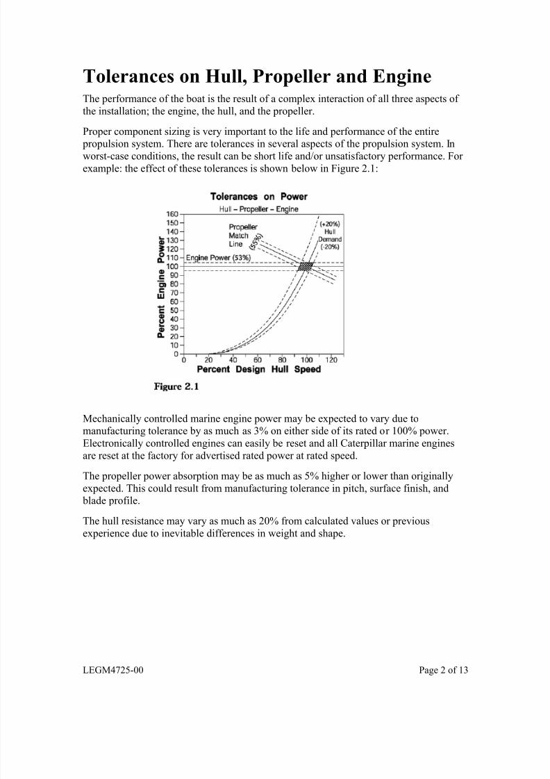
o Tolerances on Hull, Propeller and Engine
o Propeller Sizing
o Ducted Propellers (Kort Nozzles)
o Hull Types
o Rules of Thumb
Information contained in this publication may be considered ©2004 Caterpillar confidential. Discretion is recommended when distributing. All rights reserved.Materials and specifications are subject to change without notice. Printed in U.S.A.
LEGM4725-00 Page 1 of 13
7/28/2019 Eficiencia de La Embarcacion
http://slidepdf.com/reader/full/eficiencia-de-la-embarcacion 2/13
7/28/2019 Eficiencia de La Embarcacion
http://slidepdf.com/reader/full/eficiencia-de-la-embarcacion 3/13
Propeller SizingThe propeller is as important as the hull or the engine to the performance of the boat.
The propeller directly influences top speed, fuel efficiency, and engine life.
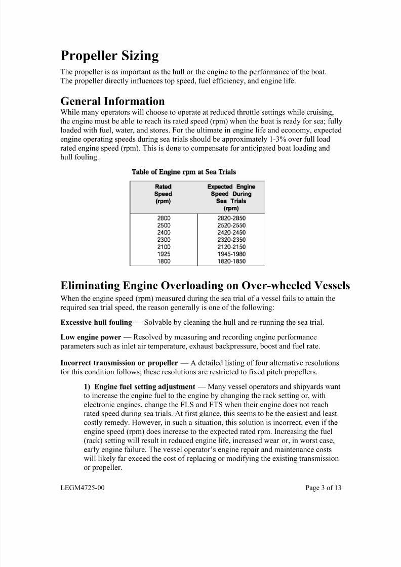
General InformationWhile many operators will choose to operate at reduced throttle settings while cruising,
the engine must be able to reach its rated speed (rpm) when the boat is ready for sea; fullyloaded with fuel, water, and stores. For the ultimate in engine life and economy, expected
engine operating speeds during sea trials should be approximately 1-3% over full load
rated engine speed (rpm). This is done to compensate for anticipated boat loading andhull fouling.
Eliminating Engine Overloading on Over-wheeled Vessels
When the engine speed (rpm) measured during the sea trial of a vessel fails to attain therequired sea trial speed, the reason generally is one of the following:
Excessive hull fouling — Solvable by cleaning the hull and re-running the sea trial.
Low engine power — Resolved by measuring and recording engine performance
parameters such as inlet air temperature, exhaust backpressure, boost and fuel rate.
Incorrect transmission or propeller — A detailed listing of four alternative resolutions
for this condition follows; these resolutions are restricted to fixed pitch propellers. 1) Engine fuel setting adjustment — Many vessel operators and shipyards want
to increase the engine fuel to the engine by changing the rack setting or, withelectronic engines, change the FLS and FTS when their engine does not reachrated speed during sea trials. At first glance, this seems to be the easiest and least
costly remedy. However, in such a situation, this solution is incorrect, even if the
engine speed (rpm) does increase to the expected rated rpm. Increasing the fuel(rack) setting will result in reduced engine life, increased wear or, in worst case,
early engine failure. The vessel operator’s engine repair and maintenance costs
will likely far exceed the cost of replacing or modifying the existing transmission
or propeller.
LEGM4725-00 Page 3 of 13
7/28/2019 Eficiencia de La Embarcacion
http://slidepdf.com/reader/full/eficiencia-de-la-embarcacion 4/13
2) High idle adjustment — Another often-considered alternative is increasing
high idle engine speed on mechanical engines above the specified free runningspeed. This will not provide the desired results since the fuel stop is already at the
maximum fuel position, and an increase in high idle will not result in any
appreciable speed change.
3) Properly sized propeller and/or reduction ratio — The correct, but morecostly, remedy is to re-pitch, or install a properly matched propeller and/or
transmission ratio to allow the engine to operate within its rating guidelines.
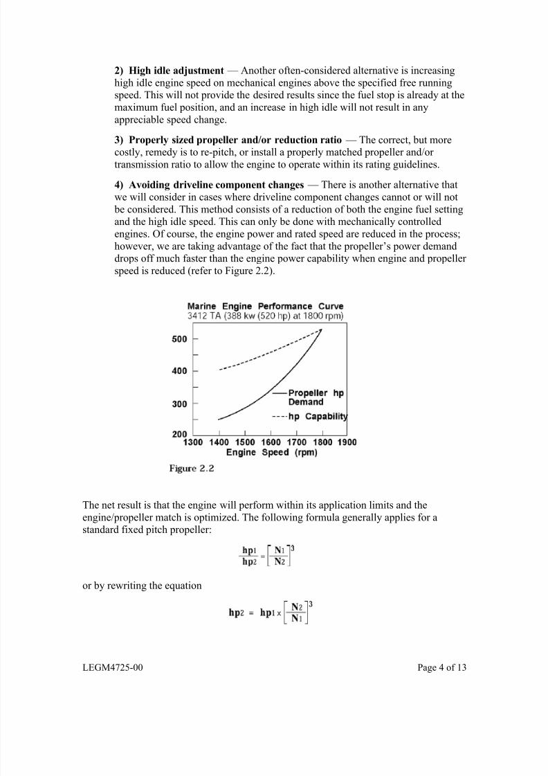
4) Avoiding driveline component changes — There is another alternative that
we will consider in cases where driveline component changes cannot or will not
be considered. This method consists of a reduction of both the engine fuel settingand the high idle speed. This can only be done with mechanically controlled
engines. Of course, the engine power and rated speed are reduced in the process;
however, we are taking advantage of the fact that the propeller’s power demanddrops off much faster than the engine power capability when engine and propeller
speed is reduced (refer to Figure 2.2).
The net result is that the engine will perform within its application limits and the
engine/propeller match is optimized. The following formula generally applies for astandard fixed pitch propeller:
or by rewriting the equation
LEGM4725-00 Page 4 of 13
7/28/2019 Eficiencia de La Embarcacion
http://slidepdf.com/reader/full/eficiencia-de-la-embarcacion 5/13
Where:
hp1 = Engine power produced at the full throttle speed recorded during the sea trial. This power level is determined by referring to the appropriate marine engine performance
curve corresponding to the original engine rating sold by the dealer and reading the
power on the curve at the recorded speed.
hp2 = Calculated propeller power demand at the new reduced engine speed (rpm) proposed for this application.
N1 = Engine speed (rpm) observed and recorded during the original sea trial — prior to
fuel setting and high idle modifications. (This speed should always be measured with a
precision tachometer.)
N2 = New, reduced engine speed (rpm) which must be determined in order to provide an
acceptable engine, transmission, and propeller match.
For example: Consider a 3408B DITA engine, sold at a continuous rating of 365 hp at
1800 rpm. During the sea trial, the maximum attainable engine speed was only 1620 rpm.This engine was operating in an unacceptable overload (or lug ) condition. The Marine
Engine Performance Curve (for a continuous rating of 272 kw [365 hp] at 1800 rpm)indicates that the engine was producing (and the propeller was demanding) 344 hp at the
limited speed of 1620 rpm. This power requirement exceeds the approved continuous
rating of 330 hp at 1620 rpm. The solution is to further reduce the rpm until the approvedengine rating, as shown on the 3408B marine engine rating maximum limit curve,
exceeds the propeller demand.
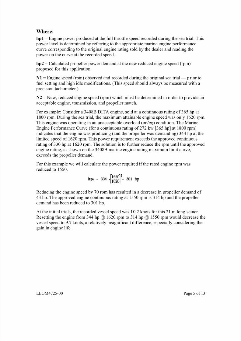
For this example we will calculate the power required if the rated engine rpm was
reduced to 1550.
Reducing the engine speed by 70 rpm has resulted in a decrease in propeller demand of
43 hp. The approved engine continuous rating at 1550 rpm is 314 hp and the propeller demand has been reduced to 301 hp.
At the initial trials, the recorded vessel speed was 10.2 knots for this 21 m long seiner.
Resetting the engine from 344 hp @ 1620 rpm to 314 hp @ 1550 rpm would decrease the
vessel speed to 9.7 knots, a relatively insignificant difference, especially considering thegain in engine life.
LEGM4725-00 Page 5 of 13
7/28/2019 Eficiencia de La Embarcacion
http://slidepdf.com/reader/full/eficiencia-de-la-embarcacion 6/13
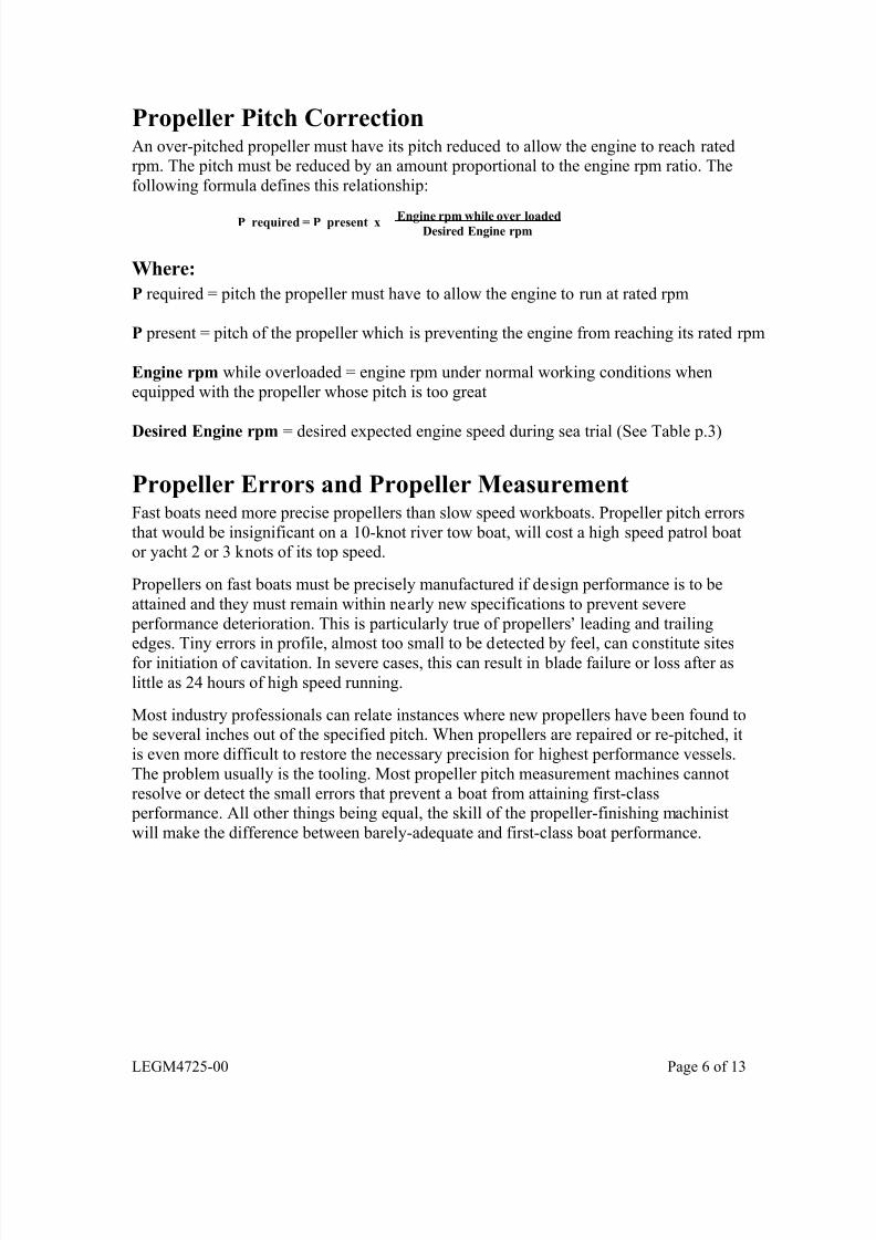
Propeller Pitch CorrectionAn over-pitched propeller must have its pitch reduced to allow the engine to reach ratedrpm. The pitch must be reduced by an amount proportional to the engine rpm ratio. The
following formula defines this relationship:
P required = P present x Engine rpm while over loadedDesired Engine rpm
Where:
P required = pitch the propeller must have to allow the engine to run at rated rpm
P present = pitch of the propeller which is preventing the engine from reaching its rated rpm
Engine rpm while overloaded = engine rpm under normal working conditions when
equipped with the propeller whose pitch is too great
Desired Engine rpm = desired expected engine speed during sea trial (See Table p.3)
Propeller Errors and Propeller MeasurementFast boats need more precise propellers than slow speed workboats. Propeller pitch errors
that would be insignificant on a 10-knot river tow boat, will cost a high speed patrol boator yacht 2 or 3 knots of its top speed.
Propellers on fast boats must be precisely manufactured if design performance is to be
attained and they must remain within nearly new specifications to prevent severe
performance deterioration. This is particularly true of propellers’ leading and trailing
edges. Tiny errors in profile, almost too small to be detected by feel, can constitute sitesfor initiation of cavitation. In severe cases, this can result in blade failure or loss after as
little as 24 hours of high speed running.
Most industry professionals can relate instances where new propellers have been found to be several inches out of the specified pitch. When propellers are repaired or re-pitched, it
is even more difficult to restore the necessary precision for highest performance vessels.
The problem usually is the tooling. Most propeller pitch measurement machines cannot
resolve or detect the small errors that prevent a boat from attaining first-class performance. All other things being equal, the skill of the propeller-finishing machinist
will make the difference between barely-adequate and first-class boat performance.
LEGM4725-00 Page 6 of 13
7/28/2019 Eficiencia de La Embarcacion
http://slidepdf.com/reader/full/eficiencia-de-la-embarcacion 7/13
Propeller Measurement ToolsThere are several basic types of tools commonly used for propeller pitch measurement:
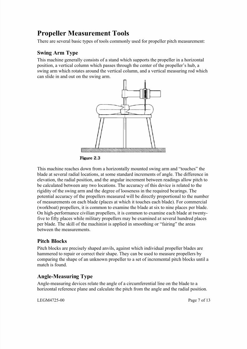
Swing Arm Type
This machine generally consists of a stand which supports the propeller in a horizontal position, a vertical column which passes through the center of the propeller’s hub, a
swing arm which rotates around the vertical column, and a vertical measuring rod which
can slide in and out on the swing arm.
This machine reaches down from a horizontally mounted swing arm and “touches” the
blade at several radial locations, at some standard increments of angle. The difference inelevation, the radial position, and the angular increment between readings allow pitch to
be calculated between any two locations. The accuracy of this device is related to the
rigidity of the swing arm and the degree of looseness in the required bearings. The potential accuracy of the propellers measured will be directly proportional to the number
of measurements on each blade (places at which it touches each blade). For commercial
(workboat) propellers, it is common to examine the blade at six to nine places per blade.
On high-performance civilian propellers, it is common to examine each blade at twenty-five to fifty places while military propellers may be examined at several hundred places
per blade. The skill of the machinist is applied in smoothing or “fairing” the areas
between the measurements.
Pitch Blocks
Pitch blocks are precisely shaped anvils, against which individual propeller blades arehammered to repair or correct their shape. They can be used to measure propellers by
comparing the shape of an unknown propeller to a set of incremental pitch blocks until a
match is found.
Angle-Measuring Type
Angle-measuring devices relate the angle of a circumferential line on the blade to ahorizontal reference plane and calculate the pitch from the angle and the radial position.
LEGM4725-00 Page 7 of 13

7/28/2019 Eficiencia de La Embarcacion
http://slidepdf.com/reader/full/eficiencia-de-la-embarcacion 8/13
Ducted Propellers (Kort Nozzles)
The propeller duct, sometimes called a Kort nozzle is a ring, wrapped around a generally
square-tipped, propeller. The ring has an airfoil-shaped cross section.
The ducted propeller is best used on vessels such as trawlers, tugs, and towboats with towingspeeds of 3-10 knots. Ducted propellers should not be used on relatively fast vessels.
To aid in selection, perform the following calculation. If the result is less than 30, the
use of the ducted propeller should not be considered as it may result in a net loss of
vessel performance.
Where:Bp = Basic Propeller Design Variable
srpm = Propeller Shaft Speed (rpm)
shp = Shaft Horsepower (shp)
Va = Velocity of Advance of the Propeller (knots) generally equals 0.7 to 0.9 times
boat speed
The nozzle configuration or profile most often used is a No. 19A nozzle although a No. 37 specifically designed for backing is obtainable. Nozzles are made of mild steel
with a stainless steel liner to stand up to erosion. They may be mounted to steel, wood, or
fiberglass hulls.
LEGM4725-00 Page 8 of 13

7/28/2019 Eficiencia de La Embarcacion
http://slidepdf.com/reader/full/eficiencia-de-la-embarcacion 9/13
A comparison of bollard pull ahead and astern for the open water propeller versus the
No. 19A (taken as 100% in ahead) and the No. 37 nozzle follows.
Ahead Astern
Nozzle No. 19A
Nozzle No. 37Open Propeller
(B4.70 Type)
59%
82%55%
100%
99%69%
These are actual figures for a 1491 kW (2000 hp) installation with 2007 mm (79 inch)
diameter propellers. A larger diameter open propeller would show up somewhat better,
though not as good as the nozzles.
More specific information on ducted propeller systems generally can be obtained from propeller manufacturers, many of which also manufacture propeller ducts.
Hull TypesAll hull types discussed here refer only to the portion of the hull below the waterline.
What is above the waterline concerns seaworthiness, seakindliness, stability, comfort, and
eye appeal, but has little impact on the propulsion machinery.
There are two basic types of hulls: Displacement Hulls and Planing Hulls. There are alsosome special types of hulls. These include the Semi-Displacement Hull, Catamaran,
Wave-Piercing Catamaran, Hydrofoil, Surface Effects Ship (with both flexible skirts and
rigid sidewalls), and the Small-Waterplane-Area-Twin-Hull (SWATH) Ship.
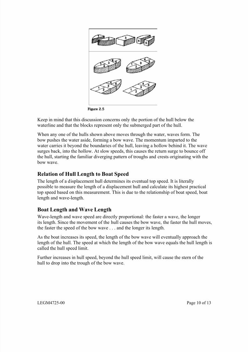
Displacement HullA displacement hull can be described in most basic terms as a block, with tapered ends.
To illustrate the basic shapes this allows, five blocks in what are rearranged to form four simple, but fundamental forms cover most all displacement hull forms.
LEGM4725-00 Page 9 of 13
7/28/2019 Eficiencia de La Embarcacion
http://slidepdf.com/reader/full/eficiencia-de-la-embarcacion 10/13
Keep in mind that this discussion concerns only the portion of the hull below thewaterline and that the blocks represent only the submerged part of the hull.
When any one of the hulls shown above moves through the water, waves form. The
bow pushes the water aside, forming a bow wave. The momentum imparted to the
water carries it beyond the boundaries of the hull, leaving a hollow behind it. The wavesurges back, into the hollow. At slow speeds, this causes the return surge to bounce off
the hull, starting the familiar diverging pattern of troughs and crests originating with the
bow wave.
Relation of Hull Length to Boat Speed
The length of a displacement hull determines its eventual top speed. It is literally
possible to measure the length of a displacement hull and calculate its highest practicaltop speed based on this measurement. This is due to the relationship of boat speed, boat
length and wave-length.
Boat Length and Wave Length
Wave-length and wave speed are directly proportional: the faster a wave, the longer
its length. Since the movement of the hull causes the bow wave, the faster the hull moves,the faster the speed of the bow wave . . . and the longer its length.
As the boat increases its speed, the length of the bow wave will eventually approach the
length of the hull. The speed at which the length of the bow wave equals the hull length is
called the hull speed limit.
Further increases in hull speed, beyond the hull speed limit, will cause the stern of thehull to drop into the trough of the bow wave.
LEGM4725-00 Page 10 of 13
7/28/2019 Eficiencia de La Embarcacion
http://slidepdf.com/reader/full/eficiencia-de-la-embarcacion 11/13
This has the following bad effects:
• air can enter the displacement hull’s propeller(s) (reducing propeller thrust)
• the belly of the hull is exposed to the oncoming waves (increasing hull resistance)
• the increased incline of the propeller shaft(s) reduces the amount of shaft thrust for
forward motion (part of the forward component of propeller thrust is wasted inholding up the stern of the boat).
This greatly increases the hull’s resistance-to-further-speed-increase. To go faster, thedisplacement hull must climb the crest of its own bow wave. For example, the last 10%
of a displacement hull’s top speed costs 27% of its engine power (and fuel consumption).
Mathematical Representation of Hull Speed Ratio
This relationship can be described mathematically.
When the bow wave length is equal to the hull length, the speed length ratio formula can be expressed as follows:
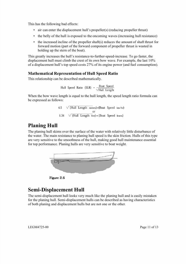
Planing HullThe planing hull skims over the surface of the water with relatively little disturbance of the water. The main resistance to planing hull speed is the skin friction. Hulls of this type
are very sensitive to the smoothness of the hull, making good hull maintenance essentialor top performance. Planing hulls are very sensitive to boat weight.f
Semi-Displacement HullThe semi-displacement hull looks very much like the planing hull and is easily mistakenfor the planing hull. Semi-displacement hulls can be described as having characteristics
of both planing and displacement hulls but are not one or the other.
LEGM4725-00 Page 11 of 13

7/28/2019 Eficiencia de La Embarcacion
http://slidepdf.com/reader/full/eficiencia-de-la-embarcacion 12/13
Displacement hulls have trouble with speed length ratios above 4.5 (1.34) due to their
hull shape. The planing hulls have difficulties below speed length ratios of approximately8.4 (2.5) because of their straight fore-and-aft lines.
Semi-displacement hulls are designed to operate well in this speed range.
Semi-displacement hulls are characterized by the angle of the quarter-beam after-body
buttock line. Visualize a pair of vertical, parallel planes intersecting the hull — midwayfrom the longitudinal center of the hull — to the waterline at the side of the boat. The
intersection of the planes — with the bottom of the hull near the stern — form thequarter-beam after-body buttock line (there are two, one on each side, but they have the
same shape). The angle of the quarter-beam buttock line is formed between it and a line parallel to the at-rest waterline, fig. 2.8.
If the angle of the quarter-beam buttock line is very small (less than 2 degrees), the hull iscapable of planing performance. At an angle of 4 degrees, the limiting speed length ratio
will be around 2.0. An angle of 7 degrees will limit the speed to length ratios of 1.5, or
just above displacement hull speeds. These angles should be measured relative to the
hull’s waterline at rest.
LEGM4725-00 Page 12 of 13

7/28/2019 Eficiencia de La Embarcacion
http://slidepdf.com/reader/full/eficiencia-de-la-embarcacion 13/13
LEGM4725-00 Page 13 of 13
Rules of Thumb
Power to Reach Hull SpeedA useful rule of thumb for vessels below 100 tons displacement is:
Power to Reach Hull Speed horsepower = 5 x [Displacement long tons]
Fuel ConsumptionA useful rule of thumb for basic budgetary purposes is:
Fuel Consumption = 1 Liter per hour per 5 horsepower