applications of multiphysical geomechanics in underground
TRANSCRIPT
EJECE – 13/2009 Failure in multiphase geomaterials, pages 937 to 962
Applications of multiphysical geomechanics in underground nuclear waste storage Antonio Gens*, Benoit Garitte*, Sebastià Olivella* and Jean Vaunat* * Universitat Politècnica de Catalunya, Departament d’Enginyeria del Terreny Jordi Girona 1-3, Edifici D-2, 08034 Barcelona, Spain [email protected] [email protected] [email protected] [email protected]
ABSTRACT: Deep geological disposal in suitable host rocks is the favoured strategy for the storage and disposal of heat-emitting high level nuclear waste. A rational design of repositories requires a good understanding of the interacting thermo-hydro-mechanical phenomena that occur in the engineered barrier and adjacent rock. To this end, a multiphysical formulation is described that allows the performance of coupled THM analyses capable of reproducing observed phenomena. The formulation and computer code is applied to the simulation of two large scale tests: a mine-by test involving the excavation of a shaft in an argillaceous rock and a large-scale high- temperature heating test in fractured rock.
RÉSUMÉ: La stratégie préconisée actuellement pour le stockage et le dépôt de déchets de haute radioactivité émettant de la chaleur est de les disposer dans des couches géologiques profondes appropriées. Un design rationnel des sites de stockage exige une bonne compréhension des phénomènes thermo-hydro-mécaniques interagissant au niveau de la barrière ouvragée et de la roche hôte proche. Pour y parvenir une formulation multiphysique, permettant de réaliser des analyses couplées THM et capable de reproduire les phénomènes observés, est décrite. La formulation est appliquée à la simulation de deux tests à échelle réelle : un essai dit « mine-by-test » concernant l’excavation d’un puits dans une roche argileuse et un test de chauffage à haute température dans une roche fracturée.
KEY WORDS: coupled analysis, THM formulation, nuclear waste disposal, argillaceous rock, fractured rock
MOTS-CLÉS: analyse couplée, formulation THM, site de stockage de déchets radioactif, roche argileuse, roche fracturée
EJECE – 13/2009. Failure in multiphase geomaterials
1. Introduction
The two main nuclear processes that may give rise to energy production are fission and fusion. In nuclear fission, a heavy nucleus (generally uranium) captures a neutron and, as a consequence, splits in two releasing a number of additional neutrons and large amounts of energy. The use of this chain reaction in a controlled manner is the basis for energy production. In nuclear fusion, two light nuclei join together to form a heavier helium nucleus. Again, a large amount of energy is released. The most suitable fusion reaction in earth conditions is the combination of deuterium and tritium. However, and in spite of a large research effort invested in fusion, nuclear energy production must rely on fission for the foreseeable future.
According to the IAEA (International Atomic Energy Agency), in 2009 there are 436 nuclear power reactors operating worldwide with an installed capacity of 370,221MW. Ten new nuclear power plants were started in 2008. Existing reactors produced 2600 billion kWh accounting for about 15 % of the total electricity generated in the world. A main issue for the nuclear power industry is the appropriate management of the radioactive waste, especially high-level radioactive waste (HLW) containing long-lived heat-emitting radionuclides.
Any disposal system should in principle guarantee that the waste is removed from the human environment, the waste is isolated and contained over long periods of time (depending on waste type) and only small release rates will occur once the complete isolation period is over. A variety of procedures have been put forward to solve the problem of radioactive waste disposal: a) space disposal, b) ice sheet disposal, c) ocean bed disposal, d) disposal beneath the seabed, e) nuclear transmutation, and f) geological disposal
Currently, only options e) and f) are the subject of intense research activity. Transmutation of the most harmful long-lived radionuclides does offer the possibility to reduce the requirements applied to a long-term disposal facility. This approach requires carrying out chemical separation of very radioactive materials, going well beyond present reprocessing activities. Whatever the result of this research, there will always remain significant quantities of waste to be disposed of in some other fashion. Another disposal alternative actively discussed at present is the construction of long-term intermediate storage repositories for high-level waste (HLW) for periods extending to 50 years, 100 years and even several centuries. This would require continued management and surveillance over these periods of time. The principle of deep geological disposal is the opposite; it frees future generation from the burden created by our present activities.
Because the geomechanical implications are highest when dealing with deep geological disposal, this option for high-level radioactive waste storage is considered herein. A review of this issue has been presented in Gens (2003).
Multiphysical geomechanics in nuclear waste storage
2. Deep geological disposal
2.1. General
The aim of geological disposal of radioactive waste is to remove it from human environment and to ensure that any radionuclide release rates remain below prescribed limits (Chapman and Mc Kinley, 1987). In fact, many countries have opted for the deep geological disposal not only of HLW but of non-heat emitting long-lived medium level waste (MLW) as well. Although shallow burial is the most common method of low level waste (LLW) disposal, some countries are also considering deep geological disposal of all waste types, including LLW, because they consider the additional cost involved is compensated by the perceived enhanced safety of deep geological disposal.
All disposal designs for HLW resort to the multi-barrier concept to achieve the required degree of waste isolation. If one considers the potential path of a radionuclide from inside the canister to the biosphere, it is clear that it will need to cross several barriers, the canister itself, the backfill (engineered barrier) and the host rock (geological barrier). Each one of those elements will provide a degree of safety to the overall disposal system. Originally it was thought that each barrier should be designed in such a way to provide sufficient isolation on its own, so that a simultaneous failure of all barriers would be required for significant radioactive releases to occur. In fact, this is too restrictive and, in cases involving long-lived wastes, possibly impossible to achieve. It is more realistic to consider all the barriers acting together in a single repository system.
A typical scheme for an underground mined repository involves the sinking of deep shafts down to a depth of several hundred meters. The depth will, of course, be controlled by local geological conditions. The shafts provide access to a network of horizontal drifts that constitute the main repository area. Part of those drifts will be access tunnels and part will be devoted to nuclear waste disposal. Figure 1 shows a scheme of a disposal drift. A concrete plug separates the disposal area from the access tunnel. The space between canisters and the host rock is generally (but not always) filled by a suitable material to constitute an engineered barrier. The material most usually considered is compacted swelling clay, normally some kind of bentonite on its own or mixed with other materials like sand. However, cement-based materials (special concretes) and crushed salt (for repositories in salt rock) are also being considered for some specific applications.
The bentonite barrier fulfils several important functions. In the first instance, a very low hydraulic conductivity restricts water penetration and retards significantly solute transport due to its low diffusion coefficient and to additional sorption effects. It should also provide a favourable chemical environment and be able to self-heal if subjected to physical perturbation such as cracking and fissuring events. The adjacent rock interacts with the barrier and it also plays a significant role in the

EJECE – 13/2009. Failure in multiphase geomaterials
safety performance of the repository by providing the next barrier of isolation and retardation. Whereas the issues of failure, sliding and damage are not especially relevant for engineered barriers (except in some extreme scenarios), those features are considered more significant in the case of the host rock, especially the portion affected by the thermohydraulic effects of the waste. For this reason the behaviour of the near-field rock will be especially considered in this contribution.
Naturally geomechanics plays an important role at all stages of design and construction of a deep geological facility for the disposal of high-level nuclear waste. Specifically, there should be very significant geomechanical input concerning site investigation and site selection, civil engineering design of the facility, underground construction of the repository, and performance assessment. In many cases, these activities require the performance of numerical analysis of varying degrees of complexity. Site investigation, design and underground construction require tools and methods of the same kind as in conventional civil engineering projects. Performance assessment, in contrast, involves approaches that are more specific of this field of work and generally require a multiphysical approach.
Figure 1. Nuclear waste canister emplacement in a horizontal disposal drift
2.2. Performance assessment of deep geological repositories
To ensure the adequacy of a design of an underground repository, it is necessary to undertake a performance assessment exercise that allows the evaluation of safety in a comprehensive way. To this end, all the processes and phenomena that may affect the performance of the repository in a significant way must be considered in a systematic manner. This safety evaluation is a complex process because of the variety of materials and components of a repository and to the large number of interacting processes that potentially play a role. In addition, the performance
Multiphysical geomechanics in nuclear waste storage
assessment must consider extremely long periods of time in order to encompass the interval during which the radionuclides are potentially hazardous.
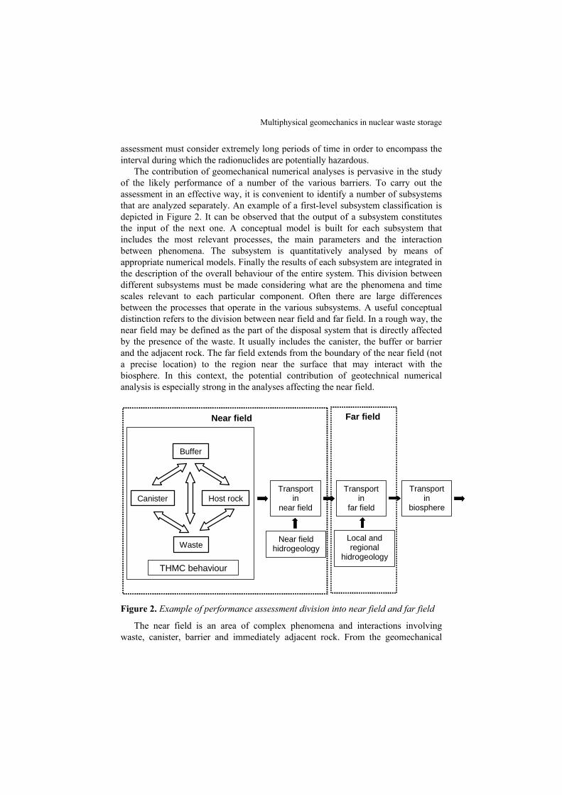
The contribution of geomechanical numerical analyses is pervasive in the study of the likely performance of a number of the various barriers. To carry out the assessment in an effective way, it is convenient to identify a number of subsystems that are analyzed separately. An example of a first-level subsystem classification is depicted in Figure 2. It can be observed that the output of a subsystem constitutes the input of the next one. A conceptual model is built for each subsystem that includes the most relevant processes, the main parameters and the interaction between phenomena. The subsystem is quantitatively analysed by means of appropriate numerical models. Finally the results of each subsystem are integrated in the description of the overall behaviour of the entire system. This division between different subsystems must be made considering what are the phenomena and time scales relevant to each particular component. Often there are large differences between the processes that operate in the various subsystems. A useful conceptual distinction refers to the division between near field and far field. In a rough way, the near field may be defined as the part of the disposal system that is directly affected by the presence of the waste. It usually includes the canister, the buffer or barrier and the adjacent rock. The far field extends from the boundary of the near field (not a precise location) to the region near the surface that may interact with the biosphere. In this context, the potential contribution of geotechnical numerical analysis is especially strong in the analyses affecting the near field.
Near field Far field
Buffer
Canister
Waste
Host rock
THMC behaviour
Transport in
far field
Transport in
biosphere
Transport in
near field
Near field hidrogeology
Local and regional
hidrogeology
Figure 2. Example of performance assessment division into near field and far field
The near field is an area of complex phenomena and interactions involving waste, canister, barrier and immediately adjacent rock. From the geomechanical
EJECE – 13/2009. Failure in multiphase geomaterials
point of view attention is concentrated on the barrier and rock, canisters and waste matrices are the concern of materials science. A number of phenomena require specific numerical analysis; e.g. the coupled thermo-hydro-mechanical and chemical (THMC) behaviour of the engineered barrier (Gens et al., 2005), the identification of the magnitude and role of the Excavation Damaged Zone, EDZ, (Vaunat and Gens, 2004), the thermohydraulic behaviour of the host rock (Gens et al., 2007) or the migration of gas through the barrier on to the rock (Olivella and Gens, 2000; Olivella and Alonso, 2008). Due to the importance of the problem, performance of large-scale tests in underground laboratories is also a characteristic feature of this field. They are carried out to advance the understanding of the phenomena and to evaluate the validity of the models used. Again, the role of numerical analyses is a very prominent feature of this work (e.g. Gens et al., 1998; Gens et al., 2009; Thomas et al., 2009). Two of those analyses are presented in this paper.
3. THM Formulation
The thermo-hydro-mechanical (THM) formulation required to perform the necessary coupled analyses must take into account the various phenomena that are likely to occur in the context of nuclear waste disposal as well as the interactions between them. Chemical processes are not considered here, they have been formulated elsewhere (Gens et al., 2005; Guimarães et al., 2007). To make it general, it is assumed that three phases exist in the porous medium: solid, liquid and gas. The formulation for saturated materials will therefore be a particular case of the general formulation. Given the nature of the problem analyzed, it is essential that, as far as possible, the formulation should be based on sound physical principles with a very general range of validity. In this way, the formulation presented should be valid for both soils and rocks, although some specific adjustment may be necessary in some cases as described in the examples given below.
For space reasons, the formulation is presented here in a summary form; a full description is given in Olivella et al. (1994). The formulation is based on a multiphase, multispecies approach. It is assumed that the porous medium is composed of three species: mineral (-), water (w) and air (a), distributed in three phases: solid (s), liquid (l) and gas (g). In the particular form presented here the mineral phase and the solid phase coincide. However, the liquid phase may contain dissolved air and the gas phase is a mixture of water vapour and dry air.
The core of the formulation is the simultaneous solution of the following global balance equations:
- mass balance of solid
( )( ) ( ) 01 =⋅∇+φ−θ∂∂
sstj [1]
where θs is the mass of solid per unit volume of solid and js is the flux of solid.
Multiphysical geomechanics in nuclear waste storage
Mass balance of water
( ) ( ) wwg
wlg
wgl
wl fSS
t=+⋅∇+φθ+φθ
∂∂ jj [2]
where fw is an external supply of water. An internal production term is not included because the total water mass balance is considered. Liquid pressure is the unknown for this equation.
Mass balance of air
( ) ( ) ( )( ) ( ) '' aag
alg
agl
al
sg
agl
al
gagl
als f
dtdSS
DtDSS
DtSSD
=+⋅∇+⋅∇φθ+θ+φ
θ+θ+θ+θ
φ jju [3]
Gas pressure is the unknown for this equation.
Energy balance for the whole medium
( )( ) )(1 QEgElEscggglllss fSESEE
t=+++⋅∇+φρ+φρ+φ−ρ
∂∂ jjji
[4]
where ic is energy flux due to conduction through the porous medium, the other fluxes (jEs, jEl, jEg) are advective fluxes of energy caused by mass motions and f Q is an internal/external energy supply. Temperature is the unknown associated with this equation.
Equilibrium (momentum balance) for the whole medium
0bσ =+⋅∇ [5]
where σ is the stress tensor and b is the vector of body forces. Displacements are the unknowns corresponding to this equation. The mass balance of solid equation is in fact eliminated and only four equations remain to be solved.
An integral part of the formulation is constituted by the set of constitutive laws and equilibrium restrictions. The constitutive equations establish the link between the state variables (or unknowns) and the dependent variables. The governing equations are finally written in terms of the unknowns when the constitutive equations are substituted in the balance equations. In addition, it is assumed that phase changes and dissolution/exsolution processes are fast compared to the transport processes that take place in porous media. Constitutive equations and equilibrium restrictions are fully described in Gens and Olivella (2001).
The formulation summarised above has been discretized in order to be used in finite element analysis. The basic formulation and numerical discretization constitute the bases of a computer code, CODE_BRIGHT, developed to perform coupled THM analysis of a variety of geotechnical problems (Olivella et al., 1996). Two cases are analyzed using the general formulation and the computer code just outlined. They refer to large-scale tests carried out in underground laboratories. The first one concerns the behaviour during excavation of an argillaceous host rock where damage effects may be significant as they may provide a preferential path for
EJECE – 13/2009. Failure in multiphase geomaterials
radionuclide migration. The second one involves the thermo-hydro-mechanical behaviour of a fractured host rock.
4. Analysis of an excavation in Callovo-Oxfordian mudstone
4.1. Description of the test
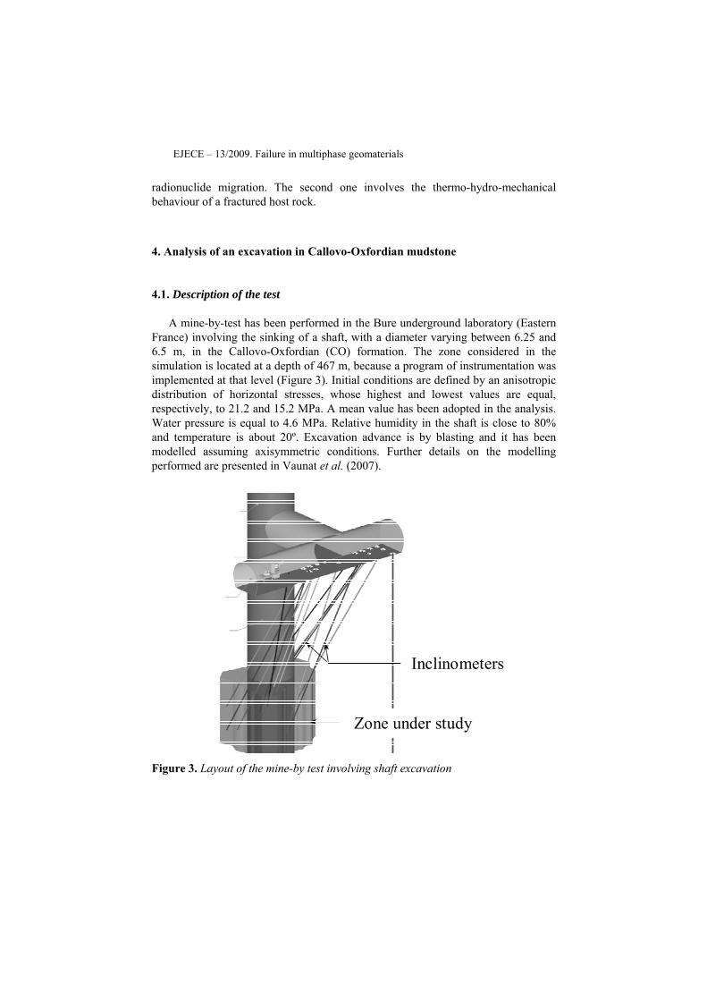
A mine-by-test has been performed in the Bure underground laboratory (Eastern France) involving the sinking of a shaft, with a diameter varying between 6.25 and 6.5 m, in the Callovo-Oxfordian (CO) formation. The zone considered in the simulation is located at a depth of 467 m, because a program of instrumentation was implemented at that level (Figure 3). Initial conditions are defined by an anisotropic distribution of horizontal stresses, whose highest and lowest values are equal, respectively, to 21.2 and 15.2 MPa. A mean value has been adopted in the analysis. Water pressure is equal to 4.6 MPa. Relative humidity in the shaft is close to 80% and temperature is about 20º. Excavation advance is by blasting and it has been modelled assuming axisymmetric conditions. Further details on the modelling performed are presented in Vaunat et al. (2007).
Inclinometers
Zone under study
Figure 3. Layout of the mine-by test involving shaft excavation
Multiphysical geomechanics in nuclear waste storage
4.2. Mechanical constitutive model
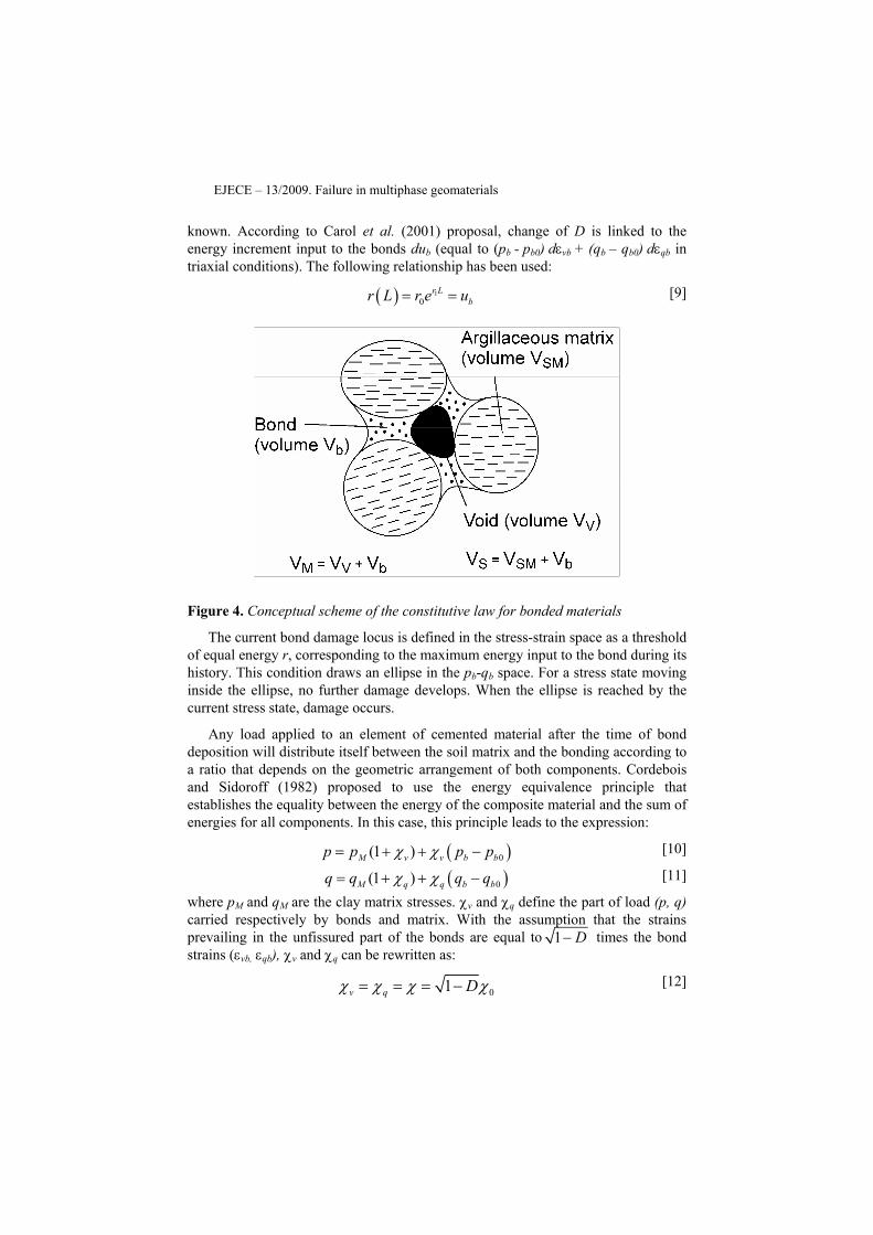
CO formation is a tertiary sedimentary mudstone of low porosity (e ≈ 0.19), low to medium expansive potential, high uniaxial compressive strength (typically between 10 to 40 MPa) and significant content in calcium carbonate (between 20% and 40%). Data generally show the structuring effect caused by deposition of calcium carbonate. Available porosity, elastic moduli and strength appear to be controlled by the proportion of carbonate (%CaCO3). A special mechanical constitutive law developed for this type of materials has been used (Vaunat and Gens, 2003). It considers the material as a composite accounting separately for the clay matrix and the bonding (Figure 4). For simplicity, the equations are expressed here in triaxial space only.
When a load is externally applied to the medium, part of the stresses will be carried by the bonds and part by the matrix. The two materials will then experience different local values of stresses and strains. These values are constrained by the condition that local strains must be compatible with externally applied deformations, by the stress-strain relationships of the matrix and the bonds and by the fact that local stresses must be in equilibrium with the external load. The model must therefore include a constitutive model for the matrix, a constitutive model for the bonds and a stress partitioning criterion to specify the way in which the applied stresses are shared.
Nonlinearity arises not only from the behaviour of the matrix but from the behaviour of the bonds as well. Bond behaviour is defined by means of a damage model that provides a relationship between bond stresses and bond strains. More specifically, the damage model established by Carol et al. (2001) has been selected, in which a logarithmic damage measure is proposed:
( )( )ln 1/ 1L D= − [6]
Equations defining this law are: ( ) 0 01 L
b b vb b vbp D K e Kε ε−= − = [7]
( ) 0 01 Lb b qb b qbq D G e Gε ε−= − = [8]
where pb and qb are the mean and deviatoric bond stress and εvb and εqb are the volumetric and shear strain (triaxial space).
D is a measure of damage or fissuring of the material and is equal to the ratio of bond fissures over the whole area of bonds. Fissures are assumed to have null stiffness while bond material between the fissures is considered as linear elastic with bulk and shear moduli Kb0 and Gb0. When D = 0, the material is intact and bond stiffness is determined by Kb0 and Gb0. As D increases, fissures develop and material stiffness reduces progressively. When D = 1, no more resisting area exists inside the bonding and bond stiffness is equal to 0. In this modelling framework, bond response is totally determined if Kb0, Gb0 and the evolution of D with load are
EJECE – 13/2009. Failure in multiphase geomaterials
known. According to Carol et al. (2001) proposal, change of D is linked to the energy increment input to the bonds dub (equal to (pb - pb0) dεvb + (qb – qb0) dεqb in triaxial conditions). The following relationship has been used:
( ) 10
r Lbr L r e u= =
[9]
Figure 4. Conceptual scheme of the constitutive law for bonded materials
The current bond damage locus is defined in the stress-strain space as a threshold of equal energy r, corresponding to the maximum energy input to the bond during its history. This condition draws an ellipse in the pb-qb space. For a stress state moving inside the ellipse, no further damage develops. When the ellipse is reached by the current stress state, damage occurs.
Any load applied to an element of cemented material after the time of bond deposition will distribute itself between the soil matrix and the bonding according to a ratio that depends on the geometric arrangement of both components. Cordebois and Sidoroff (1982) proposed to use the energy equivalence principle that establishes the equality between the energy of the composite material and the sum of energies for all components. In this case, this principle leads to the expression:
( )0(1 )M v v b bp p p pχ χ= + + − [10]
( )0(1 )M q q b bq q q qχ χ= + + −
[11]
where pM and qM are the clay matrix stresses. χv and χq define the part of load (p, q) carried respectively by bonds and matrix. With the assumption that the strains prevailing in the unfissured part of the bonds are equal to 1 D− times the bond strains (εvb, εqb), χv and χq can be rewritten as:
01v q Dχ χ χ χ= = = −
[12]

Multiphysical geomechanics in nuclear waste storage
where χ0 is a coefficient related to initial bonding intensity.
According to Equation [12], χv and χq evolve from χ0 to 0 during the process of bond damage. This mechanism is accompanied by a destructuration of the material and a progressive transfer of load from bonds to clay matrix. The damage parameter of the bonding component provides a useful variable for relating changes of permeability to increasing degradation of the material. In order to express the fact that the permeability increases when damage develops, a relationship between the intrinsic permeability and the damage variable D has been established:
2 3
00
0
11ix ixK K φ φ
φ φ⎛ ⎞ ⎛ ⎞−
= ⎜ ⎟ ⎜ ⎟−⎝ ⎠ ⎝ ⎠
% %
% % [13]
D= +%φ φ βχ [14]
where Kix0 is the permeability of the intact material at porosity Φ0 and β a material parameter.
An important set of data, currently available for a depth of 500 m, has allowed the determination of model parameters. Because of its low porosity, material exhibits an almost linear elastic response under isotropic loading up to a strain of 2% and the envelopes of peak and residual strengths appeared to be slightly curved for the range of applied stresses (up to a mean stress equal to 40MPa). As a consequence, an elastoplastic model considering Hoek & Brown criterion in conjunction with a linear elastic law has been adopted for the matrix component.
Bond behaviour has been assessed on the basis of small strain behaviour of the rock. Data from P- and S-wave velocities and triaxial tests indicate an initial Young modulus Eb0 of about 10000 MPa and Poisson’s ratio equal to 0.3. Additional triaxial tests with unloading-reloading cycles performed at different shear stress levels provide the necessary information to relate the degradation of shear moduli with applied energy. A linear trend between D (= Eb0 / Eb) and the elastic energy has been observed and the slope of the line found equal to 0.04 MPa. Initial damage locus r is equal to 0.025 MPa. Parameter χ0 has been assessed from %CaCO3 values and assigned the value 0.38. Young modulus of the destructured material is then computed such that, combined with Ebo and χ0, the value of Young’s modulus of the intact material (3800 MPa) is recovered. Parameter b0, h0, h1 and h2 are finally assessed on the basis of material brittleness. The values obtained are: b0 = 5.25, h0 = h1 = 0 and h2 = 0.025.
4.3. Results and discussion
As an example of the results obtained, Figure 5 compares, for different times, the vertical displacement measured in a vertical extensometer located at the centreline of the shaft ahead of the excavation with the computed results. The dates correspond to successive shaft floor depths of 458.3 m, 461 m, 464.1 m and 471.5 m. It can be
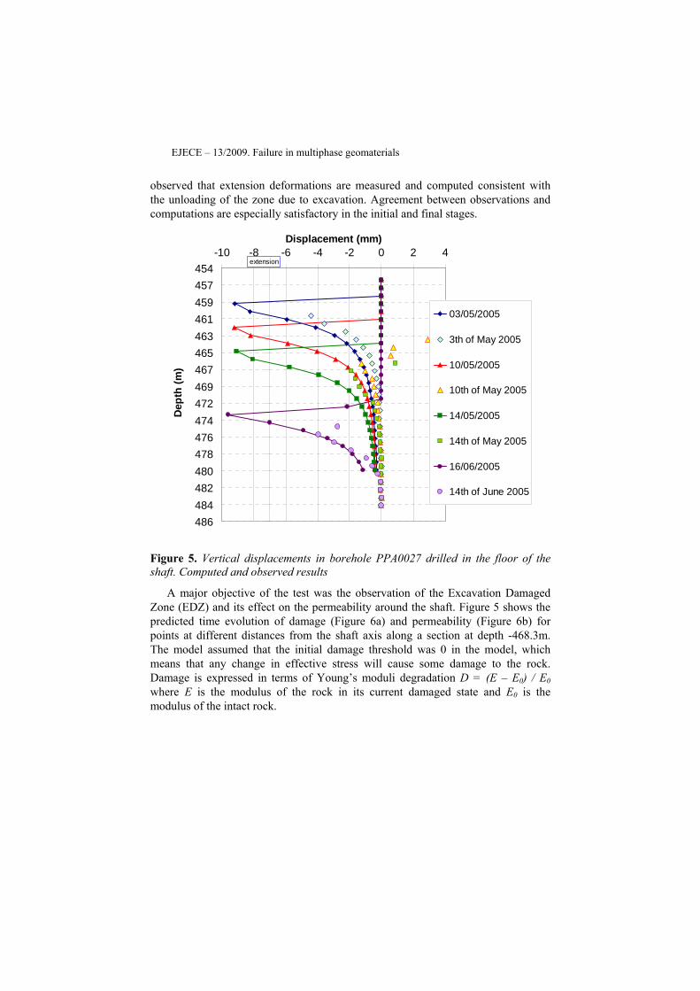
EJECE – 13/2009. Failure in multiphase geomaterials
observed that extension deformations are measured and computed consistent with the unloading of the zone due to excavation. Agreement between observations and computations are especially satisfactory in the initial and final stages.
454457459461463465467469472474476478480482484486
-10 -8 -6 -4 -2 0 2 4Displacement (mm)
Dep
th (m
)
03/05/2005
3th of May 2005
10/05/2005
10th of May 2005
14/05/2005
14th of May 2005
16/06/2005
14th of June 2005
extension
Figure 5. Vertical displacements in borehole PPA0027 drilled in the floor of the shaft. Computed and observed results
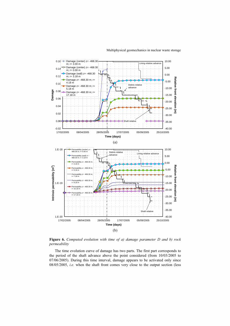
A major objective of the test was the observation of the Excavation Damaged Zone (EDZ) and its effect on the permeability around the shaft. Figure 5 shows the predicted time evolution of damage (Figure 6a) and permeability (Figure 6b) for points at different distances from the shaft axis along a section at depth -468.3m. The model assumed that the initial damage threshold was 0 in the model, which means that any change in effective stress will cause some damage to the rock. Damage is expressed in terms of Young’s moduli degradation D = (E – E0) / E0 where E is the modulus of the rock in its current damaged state and E0 is the modulus of the intact rock.
Multiphysical geomechanics in nuclear waste storage
-0.02
0.00
0.02
0.04
0.06
0.08
0.10
0.12
0.14
0.16
17/02/2005 08/04/2005 28/05/2005 17/07/2005 05/09/2005 25/10/2005
Time (days)
Dam
age
-40.00
-35.00
-30.00
-25.00
-20.00
-15.00
-10.00
-5.00
0.00
5.00
10.00
Relative front elevation (m
)
Damage (center) z= -468.30m; r= 3.00 mDamage (center) z= -468.30m; r= 0.00 mDamage (wall) z= -468.30m; r= 3.18 mDamage z= -468.30 m; r=4.18 mDamage z= -468.30 m; r=5.18 mDamage z= -468.30 m; r=17.18 m
Shaft relative
Debris relative advance
Lining relative advance
(a)
1.E-20
1.E-19
1.E-18
17/02/2005 08/04/2005 28/05/2005 17/07/2005 05/09/2005 25/10/2005
Time (days)
Intr
insi
c pe
rmea
bilit
y [m
2 ]
-40.00
-35.00
-30.00
-25.00
-20.00
-15.00
-10.00
-5.00
0.00
5.00
10.00
Relative front elevation (m
)
Permeability (center) z= -468.30 m; r= 0.00 m
Permeability (wall) z= -468.30 m; r= 3.18 m
Permeability z= -468.30 m;r= 4.18 m
Permeability z= -468.30 m;r= 5.18 m
Permeability z= -468.30 m;r= 7.18 m
Permeability z= -468.30 m;r= 8.18 m
Permeability z= -468.30 m;r= 10.18 m
Permeability z= -468.30 m;r= 17.18 m
Shaft relative
Debris relative advance Lining relative advance
(b)
Figure 6. Computed evolution with time of a) damage parameter D and b) rock permeability
The time evolution curve of damage has two parts. The first part corresponds to the period of the shaft advance above the point considered (from 10/03/2005 to 07/06/2005). During this time interval, damage appears to be activated only since 08/05/2005, i.e. when the shaft front comes very close to the output section (less

EJECE – 13/2009. Failure in multiphase geomaterials
than 1 m). When the shaft reaches the output section, the value of parameter D is equal to 5.3% under the axis of the shaft (null shear stress), almost 14% below the corner of the shaft (maximum shear stress) and less than 6% for points to the right of the shaft wall. This percentage is increased by a factor of almost two after the passage of the shaft, due to lateral decompression and the further progressive increase in effective stresses caused by the drainage of the rock due to the presence of the shaft. At a distance of 17 m, a negligible damage (0.2%) is predicted by the model. The low values of damage computed by the model are in agreement with the in situ data of rock stiffness degradation, obtained form measurement of shear velocity at different times of shaft advance. Experimental results indicate that damage is typically of the order of some percentage points only.
According to the relationship [13], the development of damage is accompanied by an increase in the intrinsic permeability Ki as shown in Figure 6b. The model predicts an increase of Ki up to 4 times the intact value (2 10-19 m2) in a zone of one meter below the shaft axis and to 6 times this value (3 10-19 m2) on the shaft wall. Naturally, the change in Ki decreases with distance to the shaft.
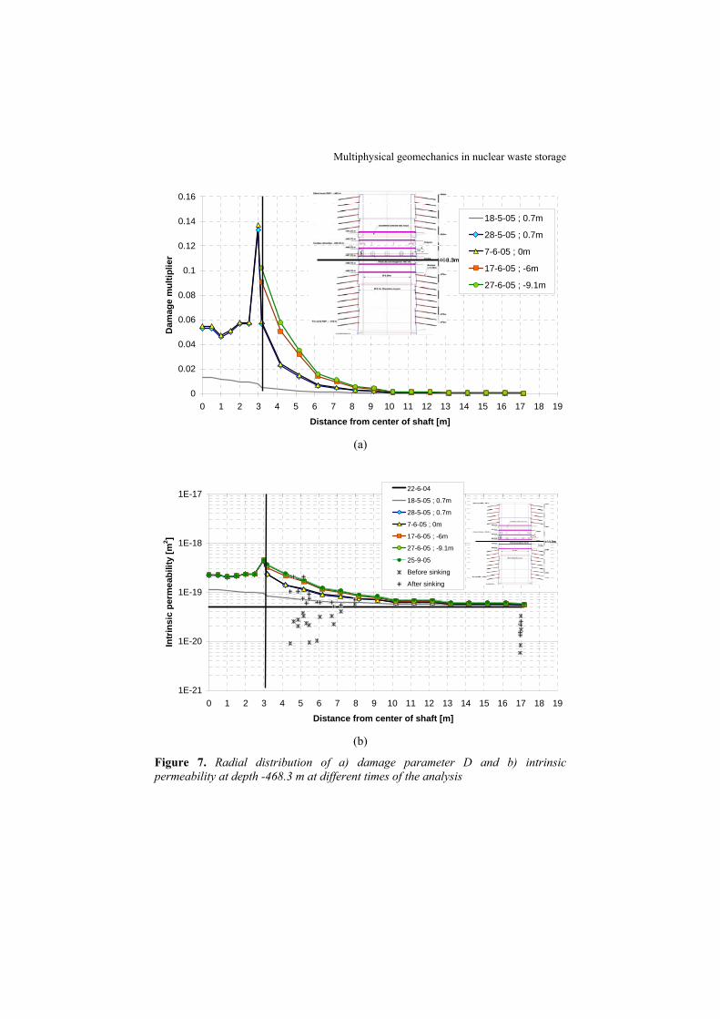
Figure 7a shows the radial distribution of damage parameter at depth 468.3 m for different times of the analysis. On 18th of May 2005, the front has just arrived at 0.7 m above the considered section and only a small damage (less than 1.5%) has been caused below the shaft floor. The shaft advance is then stopped up to 7th of June 2005. During this period, damage increases due to creep and consolidation effects and reaches 6% below the floor of the shaft and under the shaft wall (with a peak up to 14% in the zone of shear stress concentration close to the vertical of shaft). After the passage of the shaft, damage increases up to 10% at the wall of the shaft and the Excavation Damage Zone extends up to 10 m (for practical purposes, the EDZ is defined as being the zone where D > 0.5%).
In Figure 7b, the corresponding distribution of permeability is shown and compared with in situ measurements performed before (December 2004) and after (September 2005) shaft sinking. The pattern of variation of Ki with distance is quite in agreement with the data. Agreement is also reasonable in terms of absolute permeability since the predicted distribution gives an upper bound of all measurements.
Multiphysical geomechanics in nuclear waste storage
0
0.02
0.04
0.06
0.08
0.1
0.12
0.14
0.16
0 1 2 3 4 5 6 7 8 9 10 11 12 13 14 15 16 17 18 19
Distance from center of shaft [m]
Dam
age
mul
tiplie
r
18-5-05 ; 0.7m
28-5-05 ; 0.7m
7-6-05 ; 0m
17-6-05 ; -6m
27-6-05 ; -9.1m
468.3m468.3m
(a)
1E-21
1E-20
1E-19
1E-18
1E-17
0 1 2 3 4 5 6 7 8 9 10 11 12 13 14 15 16 17 18 19
Distance from center of shaft [m]
Intr
insi
c pe
rmea
bilit
y [m
2 ]
22-6-04
18-5-05 ; 0.7m
28-5-05 ; 0.7m
7-6-05 ; 0m
17-6-05 ; -6m
27-6-05 ; -9.1m
25-9-05
Before sinking
After sinking
468.3m468.3m
(b)
Figure 7. Radial distribution of a) damage parameter D and b) intrinsic permeability at depth -468.3 m at different times of the analysis
EJECE – 13/2009. Failure in multiphase geomaterials
5. Analysis of a large-scale heating test in fractured rock
5.1. Description of the test
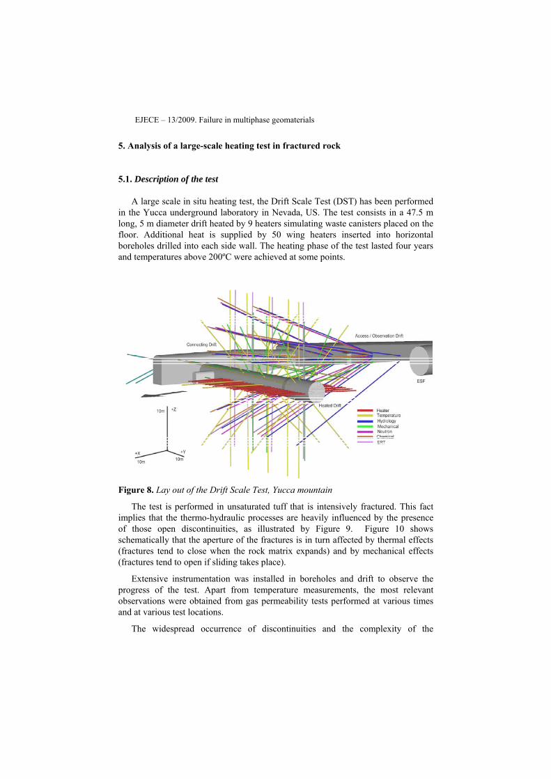
A large scale in situ heating test, the Drift Scale Test (DST) has been performed in the Yucca underground laboratory in Nevada, US. The test consists in a 47.5 m long, 5 m diameter drift heated by 9 heaters simulating waste canisters placed on the floor. Additional heat is supplied by 50 wing heaters inserted into horizontal boreholes drilled into each side wall. The heating phase of the test lasted four years and temperatures above 200ºC were achieved at some points.
Figure 8. Lay out of the Drift Scale Test, Yucca mountain
The test is performed in unsaturated tuff that is intensively fractured. This fact implies that the thermo-hydraulic processes are heavily influenced by the presence of those open discontinuities, as illustrated by Figure 9. Figure 10 shows schematically that the aperture of the fractures is in turn affected by thermal effects (fractures tend to close when the rock matrix expands) and by mechanical effects (fractures tend to open if sliding takes place).
Extensive instrumentation was installed in boreholes and drift to observe the progress of the test. Apart from temperature measurements, the most relevant observations were obtained from gas permeability tests performed at various times and at various test locations.
The widespread occurrence of discontinuities and the complexity of the

Multiphysical geomechanics in nuclear waste storage
phenomena occurring practically preclude the possibility to perform the analysis in a single homogenized medium. Consequently, a double structure formulation, described in the next section, was adopted. It can be regarded as a generalisation of the formulation described above.
Figure 9. Thermo-hydraulic processes in fractured rock at high temperature (Rutqvist & Tsang, 2003)
Figure 10. Thermomechanical effects on fracture aperture (Rutqvist & Tsang, 2003)

EJECE – 13/2009. Failure in multiphase geomaterials
5.2. Double structure approach
In this approach two overlapping media are considered simultaneously, one corresponds to the rock matrix and the other to the fracture network. They are connected by one-dimensional elements that allow heat and mass transfer between the two levels. Each one-dimensional element connects two nodes, one node in the matrix and one node in the fracture. The transport properties of the connection elements (i.e. hydraulic conductivity, thermal conductivity and vapour diffusion) are equal to the properties of the matrix. Those connection elements do not have volume i.e. do not store mass or energy. Figure 11 shows schematically the conceptual approach. The finite element mesh is duplicated and the length of the connecting elements is arbitrarily set at 0.01 m. Under these conditions, there is practically thermo-hydraulic equilibrium, i.e. fluid pressures and temperature are quite similar. However, because of the very different retention curves, degree of saturation and permeabilities of matrix and fractures may be very different.
T = 32º C Pg = 0.1 ql = 0 σx = 5 MPa
90 m
250
m
T = 32º C Pg = 0.1 ql = 0.36 mm/y σy = 8 MPa
T = 32º C, Pg = 0.1 Pl = − 0.3, uy = 0
Symmetry axis
Detail of the drift
m1 : Matrix for the Lower rock unit m2 : Matrix for the Intermediate rock unit m3 : Matrix for the Upper rock unit m5 : Fracture for the Lower rock unit m6 : Fracture for the Intermediate rock unit m7 : Fracture for the Upper rock unit m4 and m8 : Concrete m9 : Connexion between matrix and fracture
um = ut
Tm ≠ Tf
Pgm ≠ Pg
f
Plm ≠ Pl
f
l3-6
n1
n3
n2
n6
n5
n4l1matrix
l2fracture
l1-4
l2-5
um = ut
Tm ≠ Tf
Pgm ≠ Pg
f
Plm ≠ Pl
f
l3-6
n1
n3
n2
n6
n5
n4l1matrix
l2fracture
l1-4
l2-5
l3-6
n1
n3
n2
n6
n5
n4l1matrix
l2fracture
l1-4
l2-5
m7
m5
m8
m6
fracturem1
m3
m4
m2
matrix
m9
m9
m7
m5
m8
m6
fracture
m7
m5
m8
m6
fracturem1
m3
m4
m2
matrix
m1
m3
m4
m2
matrix
m9
m9
m9
m9
Figure 11. Geometry and boundary conditions for THM calculations using a double structure approach
Figures 12 and 13 show the liquid and gas permeabilities for the rock matrix and fracture network as a function of capillary pressure. Diffusion of vapour is calculated in the following way:

Multiphysical geomechanics in nuclear waste storage
( ) ( , ) wg g g gS D T P= − ∇i Iτϖ φ ρ ω [15]
where τ=1 is a tortuosity coefficient, ngS −=ϖ is an enhancement factor, ( )gSφ is
an estimation of the available area for diffusion, gρ is the gas density, ( , )gD T P is the molecular diffusion coefficient for vapour which depends on temperature and gas pressure, I is the identity matrix, and w
gω is the mass fraction of vapour in the gas phase.
1.E-25
1.E-23
1.E-21
1.E-19
1.E-17
1.E-15
1.E-13
1.E-04 1.E-03 1.E-02 1.E-01 1.E+00 1.E+01 1.E+02 1.E+03
Capillary pressure (MPa)
Liqu
id P
erm
eabi
lity
(m2)
Equivalent permeability
Matrix permeability
Fracture pemeability
Figure 12. Liquid permeability as a function of capillary pressure
1.E-25
1.E-23
1.E-21
1.E-19
1.E-17
1.E-15
1.E-13
1.E-04 1.E-03 1.E-02 1.E-01 1.E+00 1.E+01 1.E+02 1.E+03
Capillary pressure (MPa)
Gas
Per
mea
bilit
y (m
2)
Equivalent permeability
Matrix permeability
Fracture pemeability
Figure 13. Gas permeability as a function of capillary pressure
The heat power introduced in the calculations in two dimensions corresponds to both the heaters in the drift and the wing heaters in the sidewall boreholes. Since the

EJECE – 13/2009. Failure in multiphase geomaterials
model is 2D (per meter in the axial direction), the following values have been considered:
Heat power in canister-heaters:
Q (W/m)=Qtotal / (n×s) = 36400 W / (9 canister x 4.7 m) = 860 W/m
Heat power in inner wing-heaters:
Q (W/m)=Qtotal / (n×s) = 37520 W / (50 wings x 1.87 m) = 401 W/m
Heat power in outer wing-heaters:
Q (W/m)=Qtotal / (n×s) = 55300 W / (50 wings x 1.87 m) = 591 W/m
The total power (Qtotal) is divided by the number of heaters (n) and the associated length (s). The total power corresponds to 70% of the nominal power. This reduction is based on a 3D-2D comparison for the linear heat flow problem. An average reduction coefficient of the power is applied according to an exponential decay law (Q = Qo exp (-αt)). The exponential coefficient has been set to α=0.07884 1/year based on the actual decay of power supplied during the test.
Porosity changes induced by volumetric strains are distributed equally between the matrix and the fracture in this work. Fracture aperture may be related with porosity associated to the fractures, i.e. φfracture = b/s where b is the aperture and s the spacing between fractures if a family of parallel fractures is considered. The fact that porosity and aperture are proportional permits to conclude that the cubic law (k = b3/(12s)) of intrinsic permeability and Kozeny’s law are equivalent if written in the following way:
3 2 3 3
2 3 3 3
(1 )(1 )
f of f ff of of of
f of of of
bb
φ −φ φ= ≈ =
−φ φ φk k k k [16]
Where φf is the fracture porosity (φof is a reference value for φf), bf is the fracture aperture (bof is a reference value for bf) and kf is the intrinsic permeability due the presence of fractures (kof is a reference value for kf). The first part of equation [16] (Kozeny’s law) is applied either to the matrix or to the fracture. However, volumetric deformation has different effect on permeability depending on porosity values. Porosity changes may also be enhanced by dilatancy associated with shear strains (Graham and Houlsby, 1983). Therefore, current permeability (both in the matrix and in the fracture) will be the result of the combined influence of hydraulic effects (through capillary pressure or degree of saturation) and mechanical effects (through porosity or fracture aperture).
5.3. Results and discussion
The results for a coupled THM simulation are presented in this Section. They will be compared with observations at the points shown in Figure 14. Figure 15
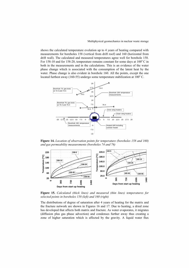
Multiphysical geomechanics in nuclear waste storage
shows the calculated temperature evolution up to 4 years of heating compared with measurements for boreholes 158 (vertical from drift roof) and 160 (horizontal from drift wall). The calculated and measured temperatures agree well for borehole 158. For 158-10 and for 158-20, temperature remains constant for some days at 100o C in both in the measurements and in the calculations. This is an evidence of the water phase change which is associated with the consumption of the latent heat by the water. Phase change is also evident in borehole 160. All the points, except the one located furthest away (160-55) undergo some temperature stabilization at 100o C.
-10
-7.5
-5
-2.5
0
2.5
5
7.5
10
12.5
15
17.5
20
-20 -17.5 -15 -12.5 -10 -7.5 -5 -2.5 0 2.5 5 7.5 10 12.5 15 17.5 20
Borehole 160: temperature measurements
Borehole 158: temperature measurements
Heated drift including canister heater
Borehole 76: gas tests at 76-3 and 76-4
Borehole 74: gas tests at 74-3 and 74-4
Inner wing heaters
Outer wing heaters
74-4
74-3
76-3
76-4
Figure 14. Location of observation points for temperature (boreholes 158 and 160) and gas permeability measurements (boreholes 74 and 76)
20
60
100
140
180
220
0
365
730
1095
1460
Days from start up heating
Tem
pera
ture
[ºC
]
158-5
158-10
158-20
158-45
158-55
20.0
60.0
100.0
140.0
180.0
220.0
0
365
730
1095
1460
Days from start up heating
Tem
pera
ture
[ºC
]
160-45 160-55
160-5
160-25
160-10
Figure 15. Calculated (thick lines) and measured (thin lines) temperatures for selected points in boreholes 158 (left) and 160 (right)
The distributions of degree of saturation after 4 years of heating for the matrix and the fracture network are shown in Figures 16 and 17. Due to heating, a dried zone has developed that affects both matrix and fracture. As water evaporates, it migrates (diffusion plus gas phase advection) and condenses further away thus creating a zone of higher saturation which is affected by the gravity. A liquid water flux
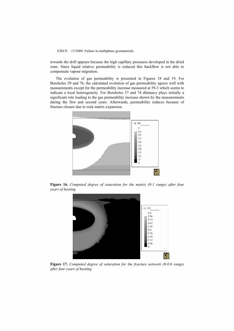
EJECE – 13/2009. Failure in multiphase geomaterials
towards the drift appears because the high capillary pressures developed in the dried zone. Since liquid relative permeability is reduced this backflow is not able to compensate vapour migration.
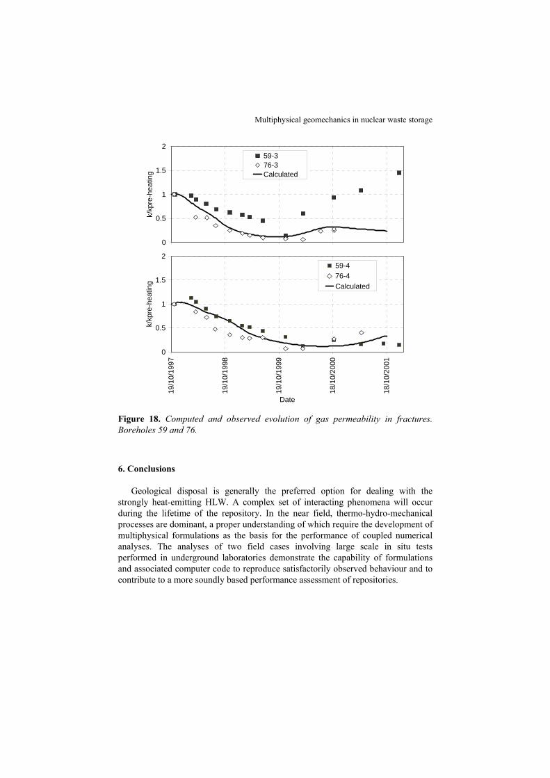
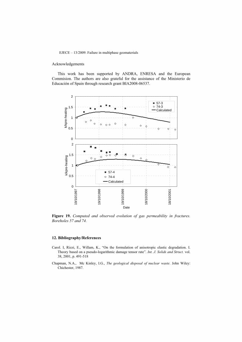
The evolution of gas permeability is presented in Figures 18 and 19. For Boreholes 59 and 76, the calculated evolution of gas permeability agrees well with measurements except for the permeability increase measured at 59-3 which seems to indicate a local heterogeneity. For Boreholes 57 and 74 dilatancy plays initially a significant role leading to the gas permeability increase shown by the measurements during the first and second years. Afterwards, permeability reduces because of fracture closure due to rock matrix expansion.
Figure 16. Computed degree of saturation for the matrix (0-1 range) after four years of heating
Figure 17. Computed degree of saturation for the fracture network (0-0.6 range) after four years of heating
Multiphysical geomechanics in nuclear waste storage
0
0.5
1
1.5
2k/
kpre
-hea
ting
59-376-3Calculated
0
0.5
1
1.5
2
19/1
0/19
97
19/1
0/19
98
19/1
0/19
99
18/1
0/20
00
18/1
0/20
01
Date
k/kp
re-h
eatin
g
59-476-4Calculated
Figure 18. Computed and observed evolution of gas permeability in fractures. Boreholes 59 and 76.
6. Conclusions
Geological disposal is generally the preferred option for dealing with the strongly heat-emitting HLW. A complex set of interacting phenomena will occur during the lifetime of the repository. In the near field, thermo-hydro-mechanical processes are dominant, a proper understanding of which require the development of multiphysical formulations as the basis for the performance of coupled numerical analyses. The analyses of two field cases involving large scale in situ tests performed in underground laboratories demonstrate the capability of formulations and associated computer code to reproduce satisfactorily observed behaviour and to contribute to a more soundly based performance assessment of repositories.
EJECE – 13/2009. Failure in multiphase geomaterials
Acknowledgements
This work has been supported by ANDRA, ENRESA and the European Commision. The authors are also grateful for the assistance of the Ministerio de Educación of Spain through research grant BIA2008-06537.
0
0.5
1
1.5
2
k/kp
re-h
eatin
g
57-374-3Calculated
0
0.5
1
1.5
2
19/1
0/19
97
19/1
0/19
98
19/1
0/19
99
18/1
0/20
00
18/1
0/20
01
Date
k/kp
re-h
eatin
g
57-474-4Calculated
Figure 19. Computed and observed evolution of gas permeability in fractures. Boreholes 57 and 74.
12. Bibliography/References
Carol. I, Rizzi, E., Willam, K., “On the formulation of anisotropic elastic degradation. I. Theory based on a pseudo-logarithmic damage tensor rate”. Int. J. Solids and Struct. vol. 38, 2001, p. 491-518
Chapman, N.A., Mc Kinley, I.G., The geological disposal of nuclear waste. John Wiley: Chichester, 1987.
Multiphysical geomechanics in nuclear waste storage
Cordebois, J.P. & Sidoroff, F., “Endommagement anisotrope en élasticité et plasticité”. J. de Mécanique Théorique et Appliquée, 1982, Numéro Spécial: p. 45-60.
Gens, A., “The role of Geotechnical Engineering for nuclear energy utilisation”. Proc. 13th. Europ. Conf. on Soil Mechanics and Geotech. Eng., 2003, Prague, vol. 3, p. 25-67.
Gens, A., Garcia-Molina, A.J., Olivella, S., Alonso, E.E., Huertas, F.. “Analysis of Full Scale In-situ Heating Test Simulating Repository Conditions”. Int. J,urnal for Numerical and Analytical Methods in Geomechanics, vol. 22, 1998, p. 515-548.
Gens, A., Guimarães, L. do N., Olivella, S., “THMC coupling in partially saturated geomaterials”, Revue européenne de génie civil, vol. 9, 2005, p. 747-765.
Gens, A., Olivella, S. (2001), “THM phenomena in saturated and unsaturated porous media”, Revue française de génie civil, 5: 693-717.
Gens A., Sánchez, M., Guimarães, L. do N., Alonso, E.E., Lloret, A., Olivella, S., Villar, M.V., Huertas, F., “A full-scale in situ heating test for high-level nuclear waste disposal: observations, analysis and interpretation”, Géotechnique, vol. 59, 2009, p. 377-399.
Gens, A.., Vaunat, J., Garitte, B. Wileveau, Y., “In situ behaviour of a stiff layered clay subject to thermal loading: observations and interpretation”. Géotechnique, vol. 57, 2007, p. 207-228.
Graham J. and Houlsby, G.T., “Anisotropic elasticity of a natural clay”, Géotechnique, vol. 33, 1983, p. 165-180.
Guimarães L. do N., Gens, A., Olivella, S., “Coupled thermo-hydro-mechanical and chemical analysis of expansive clay subjected to heating and hydration”, Transport in Porous Media, vol. 66, 2007, p. 341-372.
Olivella S., Alonso, E.E., “Gas flow through clay barriers”. Géotechnique, vol. 58, 2008, p. 157-176.
Olivella, S., Carrera, J., Gens, A., Alonso, E. E., “Nonisothermal multiphase flow of brine and gas through saline media”, Transport in Porous Media, vol. 15, 1994, p. 271-293.
Olivella S., Gens A., “Vapour transport in low permeability unsaturated soils with capillary effects”. Transport in Porous Media, vol. 40, 200, p. 219-241.
Olivella, S., Gens, A., Carrera, J., and Alonso E.E., “Numerical formulation for a simulator (CODE_BRIGHT) for the coupled analysis of saline media”. Engineering Computations, vol. 13, 1996, p. 87-112.
Rutqvist J, Tsang C.F., “Analysis of thermal-hydrologic-mechanical behaviour near an emplacement drift at Yucca Mountain”, Journal of Contaminant Hydrology, vol. 62-63, 2003, p. 637-652.
Vaunat, J., Garitte, B. Gens, A., Modelling of the REP experiment. Contribution to Modex-Rep Deliverables D5, D6 & D7. 2007, UPC, Barcelona.
Vaunat, J., Gens, A., “Bond degradation and irreversible strains in soft argillaceous rock” Proc. 12th Panamerican Conference Soil Mech. Geotech. Eng., 2003, Boston, MA, vol. 1, p. 479-484.
Vaunat, J., Gens, A., “Aspects of modelling geotechnical problems in hard soils and soft

EJECE – 13/2009. Failure in multiphase geomaterials
argillaceous rocks”. 9th Int. Symp. Numerical Models in Goemech., 2004, Ottawa, p. 37-43.
Thomas, H.R., Cleall, P.J., Dixon, D., Mitchell, H.P. “The coupled thermal-hydraulic-mechanical behaviour of a large-scale in situ heating experiment”, Géotechnique, vol. 59, 2009, p. 401-413.