mantenimiento de turbinas
TRANSCRIPT

8/20/2019 mantenimiento de turbinas
http://slidepdf.com/reader/full/mantenimiento-de-turbinas 1/575
TURBINESTEAM PATHM AINTEN AN CE A ND REPAIR
Volume 1
William P. Sanders, P. Eng.

8/20/2019 mantenimiento de turbinas
http://slidepdf.com/reader/full/mantenimiento-de-turbinas 2/575
Disclaimer: The recommendations, advice, descriptions, and themethods in this book are presented solely for educational purposes.The author and publisher assume no liability whatsoever for any lossor damage that results from the use of any of the material in this book.Use of the material in this book is solely at the risk of the user.
Sanders, William P. Turbine Steam Path Maintenance and Repair VolumeOne / William P. Sanders, P.E.
p. cm. q.cmIncludes index
ISBN 0-87814-787-X
ISBN13 978-0-87814-787-8
Copyright © 2001 by PennWell Corporation 1421 South Sheridan Road
Tulsa, OK 74112
800-752-9764 [email protected] www.pennwell-store.comwww.pennwell.com
Cover and book design by Robin Brumley
All rights reserved. No part of this book may be reproduced, stored in a
retrieval system, or transcribed in any form or by any means, electronicor mechanical including photocopying or recording, without the priorwritten permission of the publisher.
Library of Congress Cataloging-in-Publication Data
Printed in the United States of America
2 3 4 5 6 1 2 1 1 1 0 0 9 0 8

8/20/2019 mantenimiento de turbinas
http://slidepdf.com/reader/full/mantenimiento-de-turbinas 3/575
Turbine Steam Path Maintenance and Repair—Volume One
xii
PREFACE
The Turbine Steam Path, Damage,Deterioration, and Corrective Options
This book has been prepared for those technical people respon-sible for the operation and maintenance of steam turbines.
Steam turbines represent a complex technology for units com-monly designed to operate hundreds of thousands of hours whilebeing subjected to a severe environment and a variety of operatingphenomena capable of degrading their condition. These units arerequired to continually operate in a reliable, safe, and cost effective
manner. Under such circumstances, these units cannot maintaintheir original design-specified level of performance indefinitely. Allunits will deteriorate with age. Owners anticipate this, and designerswill normally leave an adequate margin, knowing that some level of such deterioration is tolerable.
The technology of steam turbines—while mature—continues toevolve. More accurate and time-responsive diagnostic tools andtechniques are becoming available to assist in predicting when a unithas deteriorated to the extent that corrective action is required.Similarly, tools are available to assist the operator in analyzing prob-lems and determining the effective corrective action best suited tothe condition causing deterioration. The improved understanding of unit condition and rates of deterioration now achieved, together withadvances in materials, should allow units to be maintained in a man-ner that will help minimize maintenance concerns and costs.
It is the premise of this book that units “as supplied” will fulfilltwo basic requirements:

8/20/2019 mantenimiento de turbinas
http://slidepdf.com/reader/full/mantenimiento-de-turbinas 4/575
Preface
xiii
• It is assumed the unit “as designed” represents an optimumselection of component sizing and arrangement
• It is assumed the unit “as delivered” meets design specifica-tion within the range of tolerances provided by the designengineer, i.e., unit components have been manufactured,assembled, tested, and installed in such a way that they arein compliance with the original design specification
The implication of this second assumption is that if nonconform-ing situations or conditions arose during the total manufacturingprocess (and exist within the unit), they have been evaluated by acompetent design authority in the engineering organization of themanufacturing company and have been assessed as not having anadverse impact on the potential performance of the unit.
In terms of turbine unit components, “design optimum” is a dif-
ficult term to define. The entire design process is one of compromiseby the designer who wants a unit to be both efficient and reliable.These requirements often represent competing demands, forcing thedesigner to select from among various elements, possibly electing todowngrade one aspect of these requirements to meet the demands of the other. This is done consciously and with detailed evaluation toprovide a balanced selection.
Units delivered by a manufacturer represent the supply of ele-ments that conform to the design principles established by his or herdesign function, and conform with the best technology available tothat supplier at the time the design specification was prepared.However, the operator must recognize that the labor and materialcosts involved in building a steam turbine are high, and turbine sup-pliers must be able to produce units at competitive levels sufficientto allow them to achieve a profit margin enabling them to sustain
business as well as finance further development.

8/20/2019 mantenimiento de turbinas
http://slidepdf.com/reader/full/mantenimiento-de-turbinas 5/575
Turbine Steam Path Maintenance and Repair—Volume One
xiv
Many power systems are currently experiencing significantchanges in how they operate. Pressures from deregulation, environ-mental concerns and legislation, and an aging fleet of power gener-ating equipment is shifting emphasis from the installation of newcapacity to the maintenance and care of the old. There is a continu-ing increase in demand for electric power but new capacity installa-tion is not keeping up with it. Operators of turbine generators aretherefore required to meet this demand with their existing fleets—
aging units requiring greater care to reduce the possibility of forcedoutages. The prospect of units experiencing extended outages asdamage is found at planned outages.
Historically, as units have aged they have tended to be used lessfrequently. They are initially placed on spinning reserve and ulti-mately placed in reserve, mothballed, or retired—their capacityreplaced with newer, more efficient units. An advantage of this dwin-
dling reserve is that older units have continued to operate at highload factors and therefore become less susceptible to the rigors of start-up, shut down, and the associated thermal transients.Unfortunately, there have also been fewer opportunities for plantmaintenance to proceed with the maintenance outages required tomaintain unit operational health.
Maintenance problems associated with keeping aging units avail-
able are only going to increase. Operators who are expected to pro-vide power on demand are going to experience even greater futurechallenges of damage and deterioration. They will be expected toidentify not only the damage, but also the causative effects, and thenfind immediate solutions that will not jeopardize system security.
This book examines the damage deterioration and failure mecha-nisms occurring with unfortunate consequences—on some units,
with monotonous regularity—within the turbine steam path. Thesevarious forms of degradation can be the result of a number of factorsrelated to conditions often beyond the control of operating and main-tenance personnel. However, even if the steam turbine is operated

8/20/2019 mantenimiento de turbinas
http://slidepdf.com/reader/full/mantenimiento-de-turbinas 6/575
Preface
xv
precisely as intended by design, and suffers no external degradingeffects for its entire operating life, the steam environment is one thatcan cause components to suffer various forms of distress. Under nor-mal circumstances, the design process selects and defines individualcomponents suitable for the design operating life of the unit (normal-ly about 200,000 hours). At a mean load factor of about 75%, thisrepresents a 30-year operating life.
A number of unavoidable influences affect the operating life of the various components comprising the turbine. These include thesteam environment itself, the stresses induced in the components byrotation, and stresses induced in various portions of the unit byexpansion of the steam through the blade passages. There are alsothe effects of the high- pressure steam, causing high-pressure dropsacross some components that must be contained by the casings.
External factors that can affect the reliability of components of the steam path and act to lower the expected operating life includethe possible formation of corrosive elements at various locationswithin the steam cycle, or impurities gaining access from in-leakageat sub-atmospheric pressures. There can be unit trips caused by anumber of circumstances, from system trip electrical faults to light-ning strikes on power lines. Many of these factors, while possiblyoccurring in a 30-year operating life, cannot be anticipated in terms
of when, where, how many, or how severe their effects might be.The damage and deterioration that occurs within the steam path
can be of several forms. It can result in a gradual material loss—thegrowth of a crack—or an immediate failure causing a forced outage.Gradual deterioration can (depending upon type and location) bemonitored and replacement parts made available, or correctiveaction taken to rectify the situation before it extends to an unaccept-
able degree. Immediate failure is most often the consequence of either mechanical rupture or the presence in the steam path of someforeign object, either generated within or having gained access fromsome external source (including “drop-ins”).

8/20/2019 mantenimiento de turbinas
http://slidepdf.com/reader/full/mantenimiento-de-turbinas 7/575
Turbine Steam Path Maintenance and Repair—Volume One
xvi
In writing this book, I have tried to present information that plantpersonnel will be able to use to make value judgments on the typeand severity of any damage, suggest possible causes, and then con-sider the most appropriate corrective actions that are available. Toaid in the recognition and classifying of operational damage anddeterioration, photographs are used to illustrate unacceptable orsuspect conditions.
Many of the damaging phenomena considered in these chaptersdo not occur in isolation. It is possible that several can and willoccur simultaneously, demonstrating that components are subjectedto more than one degrading influence. A condition may initiate dueto one damaging mechanism introducing a condition of weakness,which then allows another mechanism to become predominant anddrive a component to failure. This situation often occurs even thoughthe driving mechanism would not have been capable of causing fail-
ure had not the weakness been introduced by the first, or initiatingmechanism.
Before considering degradation and failure in any detail, it isimportant to define what constitutes failure and/or deterioration. Animportant consideration in any case of evaluation and conditionassessment of a turbine is establishing what constitutes failure. Thedefinition I find most acceptable is this: A condition exists within the
unit that while it would not prevent the unit from returning to serv- ice and continuing to develop power, it could force it from service before the next planned outage . Various other definitions exist, andthe definition of failure used in any situation—and therefore theresponsibility for correction—can be controversial. This controversyis to some extent aggravated by possibilities; e.g., a crack that hasbeen determined to exist may be predicted by the methods of frac-ture mechanics to be growing at a rate that would not cause com-
plete rupture, forcing the unit from service before the next plannedoutage.

8/20/2019 mantenimiento de turbinas
http://slidepdf.com/reader/full/mantenimiento-de-turbinas 8/575
Preface
xvii
As reserve power margins diminish, steam turbines—that cur-rently have operating periods between major maintenance outagesof three to eight years—could be forced to operate longer thanintended when they were originally returned to service. Under thesecircumstances, it is difficult when making a prediction of a unit’sfuture operation, to be certain there will not be some major changein its operating parameters. Parameters that can influence an accept-able definition of failure in any situation include the exact operating
period, the unit load pattern, and the steam conditions the unit willexperience over a number of years.
A simple and conservative solution to this definition of failurewould be to change any suspect component showing any crack orunacceptable damage-or-deformation indication. This may appear tobe an expensive option, but is considerably less expensive than aforced outage requiring weeks or months to open, repair, await
replacement parts, replace those parts, close the unit, and return it toservice.
Defining efficiency deterioration is somewhat easier. It is evenpossible to quantify such deterioration in terms of reducing steampath efficiency and unit output. What is not possible to determine isthe extent of any mechanical deterioration that may occur and causeefficiency deterioration. This is an unknown situation not recognized
until complete mechanical rupture occurs. There is normally nomanner to predict such an occurrence—damage could be in theincubation phase—even when an examination of the steam path ismade at maintenance outages.
During operation, certain situations and phenomena are knownto occur that have the potential to initiate damage or to cause dete-rioration in performance. These damaging and deteriorating phe-
nomena can be of a continuous or intermittent nature, produced asa consequence of transient operating or steam conditions. Such phe-nomena can also be the result of sudden mechanical failures of com-ponents that cause more extensive consequential damage. The most

8/20/2019 mantenimiento de turbinas
http://slidepdf.com/reader/full/mantenimiento-de-turbinas 9/575
Turbine Steam Path Maintenance and Repair—Volume One
xviii
commonly occurring of these degrading effects are related to the for-mation of moisture in the steam path or solid foreign particles, pos-sibly from the boiler or scale generated within the superheater andreheater tubes. Other sources include chemical contaminants thatare introduced, or gain access to the steam path on which they aredeposited, and possibly act as corrosive elements. The other princi-pal degrading condition is the operational phenomena occurringduring the operating life of the unit.
The first two chapters of this book provide general information.The first outlines what is considered necessary to define and consti-tute a maintenance strategy that represents management’s commit-ment to maintaining a healthy system. This chapter also outlinesmeans of monitoring conditions indicative of damage. The secondchapter deals with the spatial arrangement within the steam path andthe factors that affect it. This is important because the performance
(efficiency and reliability) of a turbine is influenced considerably bythe alignment of the unit and the resulting axial and radial clear-ances and “laps” that are achieved in the hot operating condition.
Chapters 3, 4, 5, and 6 discuss the various phenomena known toaffect both the efficiency and structural integrity of the components.In the second volume, chapters 7, 8, and 9 consider repair and refur-bishment options currently available. Fortunately, there are ever-pres-
ent advances in these technologies, and as experience is gained,newer and improved methods develop to be applied to older units sothey can continue to operate with high levels of availability—oftenwith improved efficiency. Chapter 10 considers seal systems andgland rings, and provides means of estimating the financial penaltiesassociated with excessive leakage. Seals are one area where opera-tors and maintenance personnel can influence the cost of power gen-eration, and help reduce the cost of power to their customers.
The final two chapters, 11 and 12, relate to quality and the inspec-tion of elements being manufactured to replace damaged compo-nents. This is an area where many engineers feel the cost of undertak-
8/20/2019 mantenimiento de turbinas
http://slidepdf.com/reader/full/mantenimiento-de-turbinas 10/575
Preface
xix
ing such inspections is difficult to justify. However, what happenswhen components—manufactured when they are required in anemergency to return a unit to service—have any form of fault andforce the unit from service prematurely? In such a case, the cost of inspection—ensuring that a supplier’s quality program is prepared andoperating properly—is well justified. It is often said, “There isn’t timeand money to do it right, but there is always time and money to cor-rect it.” This statement is well applied to the manufacture or repair of
components in an emergency, because the cost of a second outage is just as high as the first, and far more embarrassing.
Because the steam turbine is a thermal machine designed to con-vert thermal energy to rotation kinetic energy, I have included anappendix that provides the basic thermal relationships required tounderstand the turbine and its operation.
Situation evaluation
The more susceptible areas in any turbine unit are a function of many complex factors—individual stress levels, stress concentration,mode of operation, and the operating environment. Individual com-ponents are also greatly influenced by the expertise with which theparts were designed, manufactured, and assembled, and the oper-ating transients to which they have been subjected. The diversity of
the factors that can contribute to damage precludes any generaliza-tion of cause or value. Steam path components are subjected to highstress, both direct and alternating. Many parts operate at high tem-peratures and are of complex forms interacting with one another inunpredictable ways. These factors, when combined with load andtemperature transients that occur during operation, combine to makethe steam path highly sensitive and a major source of concern to the
designer and operator.While some concerns are common to most operators, the type of
deterioration or damage to which any component or area is subjected
8/20/2019 mantenimiento de turbinas
http://slidepdf.com/reader/full/mantenimiento-de-turbinas 11/575
Turbine Steam Path Maintenance and Repair—Volume One
xx
normally varies from unit to unit. This accounts for the variety of con-cerns expressed by maintenance staff, and the different dispositions of the various nonconforming conditions that will be developed in anysituation.
In many instances when corrective action is required, there is nooptimum solution that can be followed without deviation. Operationand load demands will often negate the optimum. At other times,costs, special tools, skills, and the availability of replacement partscould require some form of compromise. These compromise solu-tions may have to be adopted from necessity, but the final disposi-tion should provide the best balance between cost, risk, and theimmediacy of returning the unit to service.
The logical approach to maintenance and repair dispositions is:
• Consider the available alternatives in terms of the original
design requirements of the affected components
• Evaluate possible solutions in terms of departure from thedesign specified requirements
Many “repair” or “accept-as-is” dispositions will have only a lim-ited effect on unit performance, and can be readily accepted. Otherrepairs can be proposed and accepted, representing a compromised
condition. Such options should only be accepted on the basis thatthe unit will be operated with this compromised solution for as shorta period as possible, and that the selected option does not representa significant level of risk in the short term. If this is possible, plansshould be put into effect immediately to develop an acceptable solu-tion that can be undertaken within a reasonable time.
The maintenance optionsThe satisfactory performance of a steam turbine is influenced con-
siderably by the manner and expertise with which it is maintained,
8/20/2019 mantenimiento de turbinas
http://slidepdf.com/reader/full/mantenimiento-de-turbinas 12/575
Preface
xxi
and the load patterns it follows. While the plant operating engineercan control, to a large degree, the maintenance of the units for whichhe is responsible, he is unfortunately unable to exercise little influenceon operating patterns. This is a responsibility of dispatchers who havea mandate to serve the demands of their clients rather than the turbinegenerators of their system.
For maintenance to be cost-effective, it must be planned. Whensigns of distress, excessive wear, misalignment, or component dete-rioration are detected, the need for corrective action must be con-sidered. These corrective actions should help ensure the situationdoes not deteriorate further, to the extent the unit is placed on aforced outage status, severely load limited, or suffers an unaccept-ably high degree of deterioration in efficiency.
There are general maintenance requirements for any unit.Guidance for these is provided by the designer and should be fol-lowed for all routine matters. The designer will also provide recom-mendations for the operating time between opening sections of theunit for periodic maintenance and examination. During these main-tenance outages, any findings that could affect unit performancemust be reviewed in relation to their possible long-term effects.
Maintenance actionsOpening a unit for maintenance provides the opportunity to
make repairs or to install replacement parts when the necessary skillsand special purpose tools are available. Such an opening also allowsreplacement parts to be ordered, which can be placed in the unit atthe current or later outage, depending upon the delivery andrequired period of the outage. Replacement is made when an evalu-ation of any found operational nonconformance is judged to be
placing the unit at risk if returned to service without correction. Adetailed evaluation of each nonconformance should be made and itshould indicate if, and what actions are required.

8/20/2019 mantenimiento de turbinas
http://slidepdf.com/reader/full/mantenimiento-de-turbinas 13/575
Turbine Steam Path Maintenance and Repair—Volume One
xxii
The principal purpose of a steam turbine maintenance inspectionis to detect potential problems at an early stage. If this is not done,relatively minor situations could progress to the extent a forced out-age or excessive loss in unit output and efficiency could occur.During such a maintenance inspection outage, parts can be exam-ined visually for indications of failure, wear, or distortion. Also, non-destructive tests can be applied to critical components to determineif their ability to continue to perform satisfactorily has deteriorated
and if so, what remedial action should be taken, or planned.
A nonconformance in any part of the steam turbine unit is con-sidered to have occurred when there are signs of mechanical failure,excessive wear, or any form of deterioration that has the potential toadversely affect the performance of the unit. Such nonconformancesmust be reviewed for its short- and long-term effects.
As soon as unit inspection indicates a nonconforming conditionhas been found, it must be evaluated. The logic process of evaluationfor both availability and efficiency is considered in chapter 1. Thischapter outlines avenues the maintenance engineer should explorein deciding what corrective action needs to be taken. There are fourdecisions that can be reached. In some circumstances the decisionis relatively simple, and is in fact obvious. In other situations, a deci-sion is made based on the probability of failure, the possible cost of
repair, and ultimately, the reparation of consequential damages thatare the result of not taking corrective action. These four options canbe considered:
• scrap and replace
• repair
• rework
• accept-as-is
8/20/2019 mantenimiento de turbinas
http://slidepdf.com/reader/full/mantenimiento-de-turbinas 14/575
Preface
xxiii
Of these decisions, possibly the most difficult and potentiallymost controversial is the latter—accept as is—a disposition thatallows a component to return to service with no effort made to cor-rect the nonconforming condition. There are two reasons for reach-ing and deciding upon this course of action:
• There is little need to make any corrections. To make themwill add no or marginal improvement to unit performanceand the condition will not place the unit at risk
• The cost of replacing, repairing, or reworking cannot be jus- tified. This is often a judgment call on the part of the engi-neer and can only be made if he or she is aware of any risksinvolved
Such a decision should not be made as a desperation measure.The risks, if any, should be fully evaluated. The options and the prob-
ability of failure—from an extended outage to operation—must befully considered.
Therefore, the evaluation process can be a complex one.Occasionally, the solution is self-evident—such as when partial fail-ure has occurred, or when excessive damage exists. The most diffi-cult decisions are those related to suspected damage or deteriora-tion, and those for which it is difficult to determine the cause. In
these instances of uncertainty, mature judgment is required, togeth-er with knowledge of the operating and maintenance history of theunit. This knowledge should help in the evaluation. The informationin this book can also provide confidence in the selection of the finaldisposition.
The availability of replacement parts, special skills, and tools willoften influence which decision is reached. Care must be exercised to
ensure that availability or non-availability of replacement parts doesnot force the owner/operator into a decision ultimately causing more

8/20/2019 mantenimiento de turbinas
http://slidepdf.com/reader/full/mantenimiento-de-turbinas 15/575
Turbine Steam Path Maintenance and Repair—Volume One
xxiv
expense and increasing the overall risk level to an unacceptabledegree.
Often, alternatives to these potential solutions are available.Some may degrade a unit’s rating or impose other restrictions interms of maximum output, or the time for which a unit can be oper-ated. The compromise correction is ultimately more acceptable overthe short-term, while the owner/operator arranges for a more palat-able long-term solution.
William P. Sanders Richmond Hill, Ontario, Canada August, 1999

8/20/2019 mantenimiento de turbinas
http://slidepdf.com/reader/full/mantenimiento-de-turbinas 16/575
v
TABLE OF CONTENTS
List of Acronyms . . . . . . . . . . . . . . . . . . . . . ix
Foreword . . . . . . . . . . . . . . . . . . . . . . . . . . . x
Preface . . . . . . . . . . . . . . . . . . . . . . . . . . . . xii
Acknowledgements . . . . . . . . . . . . . . . . . . xxv
Chapter 1—Considerations of a Turbine Steam
Path Maintenance StrategyIntroduction . . . . . . . . . . . . . . . . . . . . . . . . . . . . . . . . . . . 1Considerations Relating to a Maintenance Strategy . . . . . . . 2The Turbine Outage . . . . . . . . . . . . . . . . . . . . . . . . . . . . . . 6Establishing the Need for Unit Shutdown . . . . . . . . . . . . . . 7Outage Scheduling . . . . . . . . . . . . . . . . . . . . . . . . . . . . . 12Interval Between Maintenance Outages . . . . . . . . . . . . . . 13The Inspection/Maintenance Outage . . . . . . . . . . . . . . . . 17The Available Corrective Options . . . . . . . . . . . . . . . . . . . 19
Distinction Between Causes and Mechanisms of Failure . . 25Component Susceptibility for Deterioration . . . . . . . . . . . . 52Instantaneous Damage or Failure . . . . . . . . . . . . . . . . . . 57Factors Contributing to Gradual Deterioration . . . . . . . . . . 59Monitoring Damage and Deterioration . . . . . . . . . . . . . . . 66Replacement Parts Strategy and Supply . . . . . . . . . . . . . . . 82References . . . . . . . . . . . . . . . . . . . . . . . . . . . . . . . . . . . 84
8/20/2019 mantenimiento de turbinas
http://slidepdf.com/reader/full/mantenimiento-de-turbinas 17/575
Turbine Steam Path Maintenance and Repair—Volume One
vi
Chapter 2—Steam Path Component Alignmentand Stage Spatial Requirements
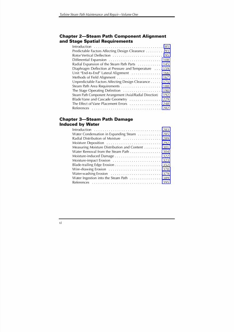
Introduction . . . . . . . . . . . . . . . . . . . . . . . . . . . . . . . . . . 85Predictable Factors Affecting Design Clearance . . . . . . . . . 93Rotor Vertical Deflection . . . . . . . . . . . . . . . . . . . . . . . . . 95Differential Expansion . . . . . . . . . . . . . . . . . . . . . . . . . . 108Radial Expansion of the Steam Path Parts . . . . . . . . . . . . 145Diaphragm Deflection at Pressure and Temperature . . . . 159Unit “End-to-End” Lateral Alignment . . . . . . . . . . . . . . . 166
Methods of Field Alignment . . . . . . . . . . . . . . . . . . . . . . 167Unpredictable Factors Affecting Design Clearance . . . . . . 175Steam Path Area Requirements . . . . . . . . . . . . . . . . . . . . 188The Stage Operating Definition . . . . . . . . . . . . . . . . . . . 190Steam Path Component Arrangement (Axial/Radial Direction) . 192Blade Vane and Cascade Geometry . . . . . . . . . . . . . . . . 229The Effect of Vane Placement Errors . . . . . . . . . . . . . . . . 248References . . . . . . . . . . . . . . . . . . . . . . . . . . . . . . . . . . 282
Chapter 3—Steam Path DamageInduced by Water
Introduction . . . . . . . . . . . . . . . . . . . . . . . . . . . . . . . . . 283Water Condensation in Expanding Steam . . . . . . . . . . . . 285Radial Distribution of Moisture . . . . . . . . . . . . . . . . . . . 289Moisture Deposition . . . . . . . . . . . . . . . . . . . . . . . . . . . 292Measuring Moisture Distribution and Content . . . . . . . . . 301Water Removal from the Steam Path . . . . . . . . . . . . . . . . 304
Moisture-induced Damage . . . . . . . . . . . . . . . . . . . . . . . 322Moisture-impact Erosion . . . . . . . . . . . . . . . . . . . . . . . . 323Blade-trailing Edge Erosion . . . . . . . . . . . . . . . . . . . . . . . 352Wire-drawing Erosion . . . . . . . . . . . . . . . . . . . . . . . . . . 370Water-washing Erosion . . . . . . . . . . . . . . . . . . . . . . . . . 379Water Ingestion into the Steam Path . . . . . . . . . . . . . . . . 389References . . . . . . . . . . . . . . . . . . . . . . . . . . . . . . . . . . 395

8/20/2019 mantenimiento de turbinas
http://slidepdf.com/reader/full/mantenimiento-de-turbinas 18/575
Table of Contents
vii
Chapter 4—Operational EventsGiving Rise to Steam Path Damage
Introduction . . . . . . . . . . . . . . . . . . . . . . . . . . . . . . . . . 397Foreign Object Impact Damage . . . . . . . . . . . . . . . . . . . 398Sources of the Impacting Objects . . . . . . . . . . . . . . . . . . 401Impact Damage Classification . . . . . . . . . . . . . . . . . . . . 409Solid-particle Erosion (Abrasion) . . . . . . . . . . . . . . . . . . . 426Scale Formation . . . . . . . . . . . . . . . . . . . . . . . . . . . . . . . 428The Erosion Mechanisms . . . . . . . . . . . . . . . . . . . . . . . . 431
Material Loss Patterns Due to SPE . . . . . . . . . . . . . . . . . . 439Protective Measures Against Erosion . . . . . . . . . . . . . . . . 459SPE Influence on Stage Performance . . . . . . . . . . . . . . . . 460Steam Path Component Rubbing . . . . . . . . . . . . . . . . . . 462Fretting Corrosion . . . . . . . . . . . . . . . . . . . . . . . . . . . . . 477References . . . . . . . . . . . . . . . . . . . . . . . . . . . . . . . . . . 486
Chapter 5—Steam Path Damage
and Deterioration from MaterialProperty Degradation
Introduction . . . . . . . . . . . . . . . . . . . . . . . . . . . . . . . . . 487Considerations of Material Structure . . . . . . . . . . . . . . . . 489High-temperature Creep . . . . . . . . . . . . . . . . . . . . . . . . 490Creep Deformation . . . . . . . . . . . . . . . . . . . . . . . . . . . . 493The Creep Mechanism . . . . . . . . . . . . . . . . . . . . . . . . . . 497Creep Rate . . . . . . . . . . . . . . . . . . . . . . . . . . . . . . . . . . 504Creep in Steam Path Components . . . . . . . . . . . . . . . . . . 507High-cycle Fatigue . . . . . . . . . . . . . . . . . . . . . . . . . . . . . 520The High-cycle Phenomena . . . . . . . . . . . . . . . . . . . . . . 522Rotating Blade Vibratory Stresses . . . . . . . . . . . . . . . . . . 525Material Properties . . . . . . . . . . . . . . . . . . . . . . . . . . . . 561Fatigue Stresses and their Representation . . . . . . . . . . . . 569Crack Growth . . . . . . . . . . . . . . . . . . . . . . . . . . . . . . . . 576HCF Failure Surface Appearance . . . . . . . . . . . . . . . . . . 579

8/20/2019 mantenimiento de turbinas
http://slidepdf.com/reader/full/mantenimiento-de-turbinas 19/575
Turbine Steam Path Maintenance and Repair—Volume One
viii
Creep Fatigue . . . . . . . . . . . . . . . . . . . . . . . . . . . . . . . . 581Temper Embrittlement . . . . . . . . . . . . . . . . . . . . . . . . . . 582Low-cycle Thermal Fatigue . . . . . . . . . . . . . . . . . . . . . . . 583Thermal Transients . . . . . . . . . . . . . . . . . . . . . . . . . . . . . 586Determination of Thermal Stresses . . . . . . . . . . . . . . . . . 596Components Operating at High Temperature . . . . . . . . . . 600References . . . . . . . . . . . . . . . . . . . . . . . . . . . . . . . . . . 604
Chapter 6
Steam Path Damage and Deterioration fromthe Deposition of Contaminants
Introduction . . . . . . . . . . . . . . . . . . . . . . . . . . . . . . . . . 607Source of Steam Path Impurities . . . . . . . . . . . . . . . . . . . 610The Composition of Deposits . . . . . . . . . . . . . . . . . . . . . 619The Removal of Chemical Deposits from the Steam Path . . 637Steam Path Cleaning Methods . . . . . . . . . . . . . . . . . . . . 639Deposition Patterns . . . . . . . . . . . . . . . . . . . . . . . . . . . . 644
Steam Path Efficiency Deterioration . . . . . . . . . . . . . . . . 659Steam Path Corrosion . . . . . . . . . . . . . . . . . . . . . . . . . . . 671Forms of the Corrosion Process . . . . . . . . . . . . . . . . . . . 677References . . . . . . . . . . . . . . . . . . . . . . . . . . . . . . . . . . 704

8/20/2019 mantenimiento de turbinas
http://slidepdf.com/reader/full/mantenimiento-de-turbinas 20/575
1
Considerations of aTurbine Steam PathMaintenance Strategy
INTRODUCTION
Although most parts of the steam turbine are capable of sufferingmechanical damage—and do sustain it—some areas or componentssuffer greater levels of deterioration than others. Why some areas inany unit are more susceptible than others is a function of many com-plex factors—individual stress levels, stress concentration, the modeof operation, operating environment, and the manner in which theunit is maintained. Other critical factors involve the operating tran-sients to which components are subjected. This diversity of factorsthat can influence the potential for damage precludes any ability to
state a generalization of causes or of value. Despite this fact, the areaof the unit having a considerable potential to affect performance—and of raising the concern of the operating and maintenance engi-neer—is the steam path.
Chapter
1

8/20/2019 mantenimiento de turbinas
http://slidepdf.com/reader/full/mantenimiento-de-turbinas 21/575
Turbine Steam Path Maintenance and Repair—Volume One
2
Components of the steam path are subjected to high stresses,direct and alternating. Many parts operate at high temperatures.Often they are complex. These elements will also interact with oth-ers in unpredictable ways. These factors, when combined with loadand steam temperature transients that commonly occur during oper-ation, make the steam path highly sensitive and a prime candidatefor deterioration. If populations of steam turbines were to bereviewed, there is a high probability that failures or problems within
the steam path would be a significant cause of deteriorating per-formance for many of them. The rotating blades would pose a majorcause within the steam path itself.
This chapter discusses strategies available to owners when theydetermine their units have suffered some form of structural deterio-ration within the steam path (to the extent corrective action is con-sidered necessary, or at least considered prudent to evaluate the con-
dition before the unit is returned to service).
When it is determined that a nonconforming situation (damage)exists within the steam path, the user must consider availableoptions. In these circumstances, it is necessary to evaluate the situa-tion and decide which action will properly utilize the technicalcapabilities and skills available to the operator. Decisions relating tothe condition and the evaluation include considerations of both cost
and time, and the potential costs of electing not to take correctiveaction during the current outage.
CONSIDERATIONS RELATING TOA MAINTENANCE STRATEGY
In order to operate turbine units in the most cost-effective man-ner, each operating organization must define a specific policy gov-

8/20/2019 mantenimiento de turbinas
http://slidepdf.com/reader/full/mantenimiento-de-turbinas 22/575
Consideration of a Turbine Steam Path Maintenance Strategy
3
erning the maintenance of T-G units. It is normally inefficient andvery costly to operate units until they are forced from service andmaintenance undertaken on an “emergency” basis. An effective pol-icy must recognize that some spare capacity must exist within thesystem, and that power must be able to be purchased or exchangedbetween neighboring and interconnected systems so units can beshut down for periods sufficient to allow them to be opened, exam-ined, and where necessary, corrective action taken.
An effective maintenance strategy for any population of steamturbines owned and operated by a single authority carries certainrequirements:
• The strategy and the corrective actions that an evaluation forany condition selects must be cost effective
• The selected corrective actions (if actions are required) must
be able to be performed within a reasonable time frame
• The selected corrective actions must not create a conditionthat will in any way compromise the availability of the unit
• The selected corrective actions must not modify the physicalcharacteristics of the steam path components to the extentthey cause a deterioration of unit efficiency beyond what is
determined to be acceptable• The selected action must be able to be performed by main-
tenance personnel available from within the plant or spe-cialized outside workers. Any required, specialized toolsmust be available as needed
Considerations of three separate outages influence (or are influ-enced by) the work scope and corrective actions at each maintenance
outage, as shown in Figure 1.2.1, i.e., the preceding outage, the onebeing entered, and the next one planned (presumably in four or more
8/20/2019 mantenimiento de turbinas
http://slidepdf.com/reader/full/mantenimiento-de-turbinas 23/575
Turbine Steam Path Maintenance and Repair—Volume One
4
years time) have to be considered. The major objectives of the plannedoutage and subsequent inspection can therefore be considered:
• To undertake normal maintenance (cleaning and replace-ment of consumable parts of the unit, such as seal strips,which upgrade or restore the efficiency level)
• To determine the unit’s condition and the possible need forcorrective action at some future outage
• To take corrective action on conditions noted at the previousoutage. These previous conditions may have been judged atthat time to be acceptable and the unit returned to servicewith a recommendation for deferred action
• To record measurements and other conditions being moni-tored to determine the rate of deterioration of any condition
that could at some future time require corrective action• To take emergency corrective action on conditions found
since the last inspection and discovered upon opening theunit. These are conditions that could prevent the unit beingreturned to service with a probability of performing at anacceptable level
If the condition(s) discovered could prevent the unit from being
returned to service, there are three possible courses of action avail-able. Each must be separately evaluated:
• To replace the damaged or deteriorated parts. To do this,replacement parts must either be available in inventory or on“just in time” delivery. The owner must evaluate the cost of extending the outage for hard-to-get parts
• To refurbish components as needed. This action is only pos-sible to the extent that components are capable of refurbish-ment. There are circumstances that would allow permanent
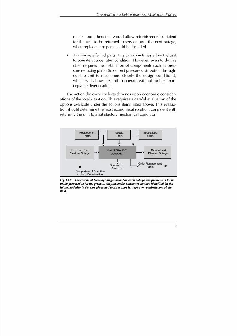
8/20/2019 mantenimiento de turbinas
http://slidepdf.com/reader/full/mantenimiento-de-turbinas 24/575
Consideration of a Turbine Steam Path Maintenance Strategy
5
repairs and others that would allow refurbishment sufficientfor the unit to be returned to service until the next outage,when replacement parts could be installed
• To remove affected parts. This can sometimes allow the unitto operate at a de-rated condition. However, even to do thisoften requires the installation of components such as pres-sure reducing plates (to correct pressure distribution through-out the unit to meet more closely the design conditions),which will allow the unit to operate without further unac-ceptable deterioration
The action the owner selects depends upon economic consider-ations of the total situation. This requires a careful evaluation of theoptions available under the actions items listed above. This evalua-tion should determine the most economical solution, consistent withreturning the unit to a satisfactory mechanical condition.
Input data fromPrevious Outage.
Data to NextPlanned Outage.
Comparison of Conditionand any Deterioration.
MAINTENANCEOUTAGE.
DimensionalRecords.
Order ReplacementParts.
SpecialTools.
SpecializedSkills.
ReplacementParts.
Fig. 1.2.1—The results of three openings impact on each outage, the previous in terms of the preparation for the present, the present for corrective actions identified for the future, and also to develop plans and work scopes for repair or refurbishment at the next.

8/20/2019 mantenimiento de turbinas
http://slidepdf.com/reader/full/mantenimiento-de-turbinas 25/575
Turbine Steam Path Maintenance and Repair—Volume One
6
THE TURBINE OUTAGEMaintenance or planned outage
This outage is scheduled. It is part of the established plan formaintaining the turbines in an acceptable condition, and mayrequire special skills and tools be made available to undertake therequired work. These outages may also be an opportunity to replace
parts that were damaged or badly worn and noted as damaged ordeteriorated at a previous outage. Replacement parts would havebeen specially ordered for this outage, and its occurrence could havebeen time dependent upon their delivery.
Forced outage
This is an unplanned outage that occurs as a consequence of
some unexpected failure or damage occurring within the turbineunit. The damage may result in a condition indicating an unaccept-able situation such as high vibration, noise, or even a unit trip. If such an incident occurs, operators must decide whether to continuein the existing mode or shut down the unit and investigate. In theevent of a unit trip, the operators may attempt to re-synchronize theunit and continue to operate.
To shut down the unit and investigate can be an expensiveoption in terms of material and labor costs associated with openingthe unit, as well as the lost generating capacity for the time the unitis not producing power. To not shut down the unit can be even moreexpensive, however, if such action neglects a condition that is in theearly stages of development, and which has caused the early systeminterruption in the first place. An uncorrected condition couldengender more serious damage to other components within the unit,and could ultimately cause extensive damage or force major com-ponents to be scrapped. Safety has to be considered in any decision

8/20/2019 mantenimiento de turbinas
http://slidepdf.com/reader/full/mantenimiento-de-turbinas 26/575
Consideration of a Turbine Steam Path Maintenance Strategy
not to shut down a unit. A condition may exist that indicates a majorand possibly catastrophic failure may occur.
Extended outage
An extended outage is the result of finding a situation during aplanned outage that causes the planned time frame for the unitinspection, cleaning, and refurbishment to be extended. Normally
this occurs when damage or deterioration is found requiring the useof nonstandard tools or skills for evaluation, or the necessaryreplacement parts being unavailable.
ESTABLISHING THE NEED
FOR UNIT SHUTDOWN
Outside of the normal period during which a unit is returned toservice and expected to operate at an adequate level of perform-ance, there are certain indications from a unit denoting a need toconsider the situation, investigate it, and possibly shut down for anunscheduled outage.
The signals indicating damage or deterioration
Station operating procedures include the need to monitor condi-tions of certain operating parameters and, when they vary outsideexpected norms, can indicate the need for emergency correctiveaction. The more common of these are shown in Figure 1.4.1, andinclude:
7

8/20/2019 mantenimiento de turbinas
http://slidepdf.com/reader/full/mantenimiento-de-turbinas 27/575
Turbine Steam Path Maintenance and Repair—Volume One
8
Vibration levels. An increase in the vibration levels of the unitrotors is an indication problems exist. There are various possiblecauses for this amplitude increase. Among the more common are:
• A change in the unit alignment. This loss of alignment maybe caused by various phenomena, and the possible causeswill need to be investigated separately. A vertical or horizon-tal shift of the bearings position can cause such a situation. If this has occurred it will be necessary to realign the shaft. Theextent to which the unit must be opened and rotors and othercomponents dismantled will depend upon its configurationand the access that can be made to the bearings
• The mechanical rupture of a component that has disruptedthe dynamic balance of the unit. Such mechanical failurewill not necessarily cause an imbalance. Shorter blades orwhole portions of a coverband may detach without signifi-cantly affecting the balance and therefore the vibration level
• Heavy rubs that have caused a shaft bend. If there has been aheavy rub caused by some transient or other condition, it isquite possible the shaft will bend to the extent balance is upset.If this has occurred it becomes necessary to open the unit,remove the affected rotor, and undertake major restoration
• Starvation of oil to the bearings (axial or thrust). If this situa-tion occurs it could cause significant, and possibly irrepara-ble damage. This situation should be rectified as quickly aspossible
Noise. One of the most significant and useful indications of dam-age or pending failure is noise from the unit. Because of the highrotations speeds, even the lightest rubs can be indicative of pending
problems. Often these noises appear and then disappear, so it shouldbe noted if the noises are associated with transient conditions, e.g.,changes in steam conditions or load. In any event:

8/20/2019 mantenimiento de turbinas
http://slidepdf.com/reader/full/mantenimiento-de-turbinas 28/575
Consideration of a Turbine Steam Path Maintenance Strategy
9
• If possible, determine if the noise is sensitive to transient con-ditions, speed, and temperature
• Identify the location of the rub as accurately as possible
• If the noise is continuous, try to determine if it is at a constantlevel and frequency. This is subjective judgment, but carefulobservation can assist
When the unit is opened, examine the region where the noiseappeared to be centered and look for rubbing damage in the form of grooves, lifted coverbands, and changes in material hardness. Thereis often a change in hardness associated with rubs that could causelater failure—the material structure on the steel will have changed,making it more brittle.
A reduction in unit output for a given steam input. If there hasbeen a step change in the output for a given steam input, this can beindicative of mechanical damage in the blade system—either a
blockage early in the steam path, or some broken elements that arereducing the efficiency of energy conversion. Often the region where
Fig. 1.4.1—Indications of a distress or a damagecondition.
8/20/2019 mantenimiento de turbinas
http://slidepdf.com/reader/full/mantenimiento-de-turbinas 29/575
Turbine Steam Path Maintenance and Repair—Volume One
10
this damage is occurring can be identified by diagnostic means anda determination made of the need to shut down and correct.
It is necessary to differentiate between a gradual reduction inoutput and the gradual wearing of seal strips. This is particularly trueafter returning to service from maintenance, and is a normal deteri-oration caused by deposits on the blade elements. Step changes aredifficult to identify, as damage will often occur during transients andthe change may not be noted when the same conditions are reestab-lished. Operating staff, particularly those with on-line monitoringcapabilities, best do this type of monitoring.
Increase in unit output at a constant valve position. Such a con-dition normally occurs because of damage in the control stage noz-zle block. This causes a change in wheel case and stage pressurethroughout the steam path. The nozzle plate will have sustaineddamage and admits more steam because of an increased flow area.If this increase is gradual it is due to some form of erosive damagerequiring refurbishment at the next available outage. However, if thechange is a “step change,” then the damage is sudden and should beexamined immediately.
Decrease in efficiency using enthalpy drop methods. If a utilityperforming an enthalpy drop test (EDT) on a regular basis finds a sig-nificant change in section state line efficiency, this normally indi-cates some condition causing a disruption of flow and energy con-version efficiency. Mechanical failure or vane deformation com-monly causes the change of efficiency and should be considered anindicator of existing problems.
Again, only step changes are significant. As EDTs may be runonly on an annual or six-month basis, a long time may pass beforesuch a condition is determined to be present by testing methods.
Station instrumentation used to monitor state line efficiency is usu-ally not sensitive enough to note changes with sufficient reliability soa unit could be opened on the basis of such results. Other forms of

8/20/2019 mantenimiento de turbinas
http://slidepdf.com/reader/full/mantenimiento-de-turbinas 30/575
Consideration of a Turbine Steam Path Maintenance Strategy
11
analysis would be required to confirm or deny the possibility of damage.
Changes in steam extraction pressures. Blade system damagewill cause a redistribution of steam pressure throughout the steampath. These changes may be minor, but if the unit is returned to sta-ble and known operating conditions the changes may be determinedto exist.
The indicators discussed above do not represent an exhaustivelist, and in many units, operators and maintenance staff become suf-ficiently familiar with individual units on their system to be aware of unit peculiarities. Under these conditions, operating staff can oftenact in an anticipatory manner and recognize characteristic changesin the units. This ability represents a valuable skill to the owners, andis only obtained from considerable experience with particular units.
System requirements
Forced outages mandate that owners arrange to meet systemrequirements by obtaining power from alternative units. This alterna-tive power can come from several sources. These include:
• Line units on spinning reserve or stand-by. These units may
be at or close to the facility but the fact that they are spinningreserve indicates their operation is less cost effective than theunits forced from service
• Older, less-efficient units on the system. This may cause atime delay but will allow system requirements to be met
• Delaying any planned or scheduled outage on other units onthe system
• Purchasing power from another utility connected to the sys-tem. This can be expensive, but may be necessary in certain

8/20/2019 mantenimiento de turbinas
http://slidepdf.com/reader/full/mantenimiento-de-turbinas 31/575
Turbine Steam Path Maintenance and Repair—Volume One
12
circumstances to meet requirements. Industrial installationsnormally have ties to the local utilities, but this can representa significant economic penalty, particularly if boilers have tobe kept running to meet process steam demands
• Adjustment of power factors and distribution voltage. Thereis a limit as to how much can be achieved by this method.On a large system this can make a difference but there is apossibility of damage to certain electrical appliances, partic-ularly from the lowering of voltage
In the event of a forced outage the owner must decide whichoption offers the best alternative for meeting system demands. Aninitial decision may be made in terms of returning service to cus-tomers, but a long-term solution may require a change of supply tomeet the most cost-effective means of meeting demands over theperiod of the forced outage.
OUTAGE SCHEDULING
A unit in service requires regular inspection or preventative
maintenance outages so it can be examined and corrective actiontaken to allow it to remain in service in an acceptable condition.There are two basic approaches to scheduling outages that providesufficient time to allow examination, the correction of knowndefects, and the detection of any deterioration that will require atten-tion at the next available outage:
• Shut down the unit and expose sections and valves to make
an examination and determine required repairs. This is prob-ably the most common approach, and is used by the major-ity of large systems. This requires the entire unit to be made

8/20/2019 mantenimiento de turbinas
http://slidepdf.com/reader/full/mantenimiento-de-turbinas 32/575
Consideration of a Turbine Steam Path Maintenance Strategy
13
unavailable to the system for a period so all sections can beworked on at the same time
• Shut down sections selectively, opening one or possibly two during a regular outage. The advantage here is that the“unavailable time” is somewhat shorter and skills are con-centrated on the opened sections. It also means that sectionsprone to damage or significant deterioration can be exam-ined more frequently
This dual approach has been found to be effective on systemsthat have both summer and winter peak load demands combinedwith relatively short periods in between, when the unit can be madeavailable for maintenance. It has also been used on large nuclearunits that must be shut down for six to seven weeks for refueling. Atthat time one section of the unit is opened and made available forreplacements or refurbishment of damage.
INTERVAL BETWEENMAINTENANCE OUTAGES
Operators of steam turbine generator units must determine theoptimum, or acceptable interval between maintenance outages andinspections. This interval between outages should be determined foreach unit within the system and must reflect not only operating andrepair costs, but also the consequences of not making such inspec-tions and detecting faults in their early stages of development. Onemanufacturer has determined that under certain conditions, andwith recognition of limitations, their unit rotors may operate for upto 10 years between major re-inspections.

8/20/2019 mantenimiento de turbinas
http://slidepdf.com/reader/full/mantenimiento-de-turbinas 33/575
Turbine Steam Path Maintenance and Repair—Volume One
14
Apart from the technical factors, the following issues should beconsidered in establishing the period between inspection outages:
• The fuel costs of the unit being removed from the system forinspection and the unit(s) started to meet load requirements,or the cost of the replacement power that will be purchased
• The anticipated load factor of the unit during the outage peri-od and its output rating
• The differential heat rates of the unit being inspected and theunits being started to meet load requirements
• The generic or historic forced outage rate of the unit
• The anticipated maintenance period
• Known labor costs and the anticipated cost escalation of
replacement parts
• The anticipated improvement in unit heat rate that occurs asa consequence of the outage
• The reserve capacity on the system and the level of risk theowner is prepared to accept in continuing to operate if theoutage is foregone
• Problems discovered on similar units owned and operated bythe owning and other utilities
These factors influence the cost of an outage and the period forwhich a unit should operate between major inspections.
The ideal situation for scheduling outages would be for a unit tobe open very infrequently; for no damage (or a minimum amount of
damage and deterioration) to be found at the outage, and then for theunit to be successfully returned to service. In fact, units are openedperiodically on a “life cycle basis”—usually between four to eight

8/20/2019 mantenimiento de turbinas
http://slidepdf.com/reader/full/mantenimiento-de-turbinas 34/575
15
years—with the possibility of this operating period being extended assystem reserve declines.
The actual opening time between major outages is dependentupon various factors including:
• the manufacturers’ recommendations. These are most oftenbased upon observations of a large population of similarunits and the experience established with these units after
different periods of operation
• known problems within the unit. These can be related toboth supplier and user-induced situations. Design weakness-es require opening the units more frequently until a perma-nent solution to a particular problem is fully identified andsolved
• the manner in which the unit has been operated since the last outage. This is a factor over which the supplier has no con-trol and, to a degree, the operator has only limited influence
Factors that influence the determination of when the unit shouldbe opened include:
• the number and type of starts since the last outage (includingvery hot, hot, warm, and cold starts)
• any temperature transients experienced since the last outage
• any excessive overspeed transients, and their duration sincethe last outage
A new unit represents the latest technology available to the sys-tem, and it is normally operated at maximum capacity. Unfortun-ately, as the unit ages, it becomes less important to the system, andcomponent material properties will tend to degrade. The unit is thennormally subjected to more cyclic operation, which consumes com-ponent life much faster.
Consideration of a Turbine Steam Path Maintenance Strategy

8/20/2019 mantenimiento de turbinas
http://slidepdf.com/reader/full/mantenimiento-de-turbinas 35/575
Turbine Steam Path Maintenance and Repair—Volume One
16
There is at present no absolute method of defining when a unitshould be removed from service for maintenance. On those occa-sions when operators know it should be shut down, some operatorscannot because of system or process demands. Under these circum-stances, the unit is operating at risk. If the operation cannot be avoid-ed entirely, it should be minimized and the transients to which it isexposed limited.
Other factors and considerations influencing the period of oper-ation before a unit is removed from service for a maintenance out-age are discussed later in this chapter.
Equivalent operating hours
A suitable method of assisting in “opening decisions” is to accu-mulate the equivalent operating hours (EOH) for any service period
after the unit is returned to service from a major outage. In account-ing for this period of operation, the EOH factors effect start ups andcan be made to include the effects of some transient operation. A for-mulation developed by one major manufacturer provides the fol-lowing equation that is applicable to their units, but with minormodification can be made to suit any unit:
EOH’s = (Nc x TC) + (NW x TW) + (NH x TH) + (NV x TV)
where:
EOH’s = Equivalent operating hours due to starts
Nc = The number of cold starts
Nw = The number of warm starts
Nh = The number of hot starts
Nv = The number of very hot starts
Tc = The weighing factor for cold starts
Tw = The weighing factor for warm starts
Th = The weighing factor for hot starts
Tv = The weighing factor for very hot starts
8/20/2019 mantenimiento de turbinas
http://slidepdf.com/reader/full/mantenimiento-de-turbinas 36/575
Consideration of a Turbine Steam Path Maintenance Strategy
17
These “time equivalent” notations for starting the unit are addedto the normal operating hours (NOH), which are included irrespec-tive of the load generated by the unit. When the total of normal oper-ation plus start up reaches some predetermined value, the unit is duefor an inspection/maintenance outage. Therefore:
EOH = ΣNOH + EOH’s
These equations can be modified to include terms accounting for
both overspeed and temperature transients. A more difficult determi-nation is the number of EOH that should form the basis of the timesat which the unit should be shut down for inspection. It is suggestedthat an EOH of 30,000 to 35,000 be considered between major out-ages. The initial and reheat temperature and the operators’ experi-ences should modify this value with the unit.
THE INSPECTION/ MAINTENANCE OUTAGE
A principal purpose of the steam path maintenance inspection isto detect potential problems at an early stage. If this is not done,
minor deterioration could progress to the extent that a forced outageor excessive loss in unit efficiency could occur. During such aninspection, parts can be examined visually for indications of failure,wear, or distortion. Non-destructive tests can be applied to criticalcomponents determining if their ability to continue performing satis-factorily has deteriorated.
The satisfactory operation of a steam turbine within a utility is
influenced to a large extent by the manner and expertise with whichit is operated and maintained. For maintenance to be cost effective itmust be planned. When signs of distress, excessive wear, misalign-

8/20/2019 mantenimiento de turbinas
http://slidepdf.com/reader/full/mantenimiento-de-turbinas 37/575
Turbine Steam Path Maintenance and Repair—Volume One
18
ment, or component deterioration are detected, the need for correc-tive action must be considered. This corrective action should ensurethe situation does not deteriorate further, or to the extent the unit isplaced into a forced outage status, is severely load limited, or suffersan unacceptably high degree of degradation in efficiency.
The cost of forced outages can be extremely high. In the case of large utility units this often requires that older, less efficient units bestarted to meet system demands or that units employing an alternate,more expensive fuel be employed. The most severe situation for util-ity systems is when reserve capacity does not exist and replacementpower cannot be purchased. At that time a blackout or brownout sit-uation occurs.
In addition to routine maintenance, monitoring, and care activi-ties, there are surveillance actions associated with a planned main-tenance outage. In such instances, upper half covers are removed toexpose the steam path for examination. This opening of the unitallows repairs to be made or replacement parts to be installed. At thistime, necessary skills and any special purpose tools that are requiredcan be made available.
Such a maintenance opening also allows replacement parts to beordered. This is done when an evaluation of any “found operationalnonconformance” is judged to place the unit at risk. An evaluationof the nonconformance will normally indicate whether a unit cansafely be returned to service, or if some temporary remedial actionis required so the situation can be corrected before restarting.
8/20/2019 mantenimiento de turbinas
http://slidepdf.com/reader/full/mantenimiento-de-turbinas 38/575
Consideration of a Turbine Steam Path Maintenance Strategy
19
THE AVAILABLECORRECTIVE OPTIONS
The type of deterioration or damage to which a component orarea is subjected varies from unit to unit. It depends upon a varietyof causes that exist, or are present as a function of the component’sdesign details and unit operating mode. These various causes can
normally account for the degree of concern the maintenance staff expresses and they influence the different dispositions that will bedeveloped regarding the nonconformances.
In many instances of damage or failure there is rarely any “best”or “perfect” solution. Instead, compromises will have to be madebased on the availability of replacement parts, overall costs, therequirements for special tools, and the skills and time available to take
corrective action. The selected disposition will also be influenced bythe level of risk associated with each possible solution in any situa-tion. The selected action should provide the best balance among cost,risk, and how quickly the unit can be returned to service.
In order to rationalize the evaluation process, conditions andmaintenance decisions have to be defined. The most important follow:
A field found nonconformance
A nonconforming situation is considered to exist when the com-ponents of the unit have changed or deteriorated to the extent thedesign requirements are no longer present. A nonconformance inany part of the steam path is considered to be present when there aresigns of structural failure, excessive wear, or any form of deteriora-tion having the potential to adversely affect the performance of the
unit. When such a nonconforming condition is confirmed, it must beviewed for both its short- and long-term effects (see chapter 11 formanufacturing nonconformances).

8/20/2019 mantenimiento de turbinas
http://slidepdf.com/reader/full/mantenimiento-de-turbinas 39/575
Turbine Steam Path Maintenance and Repair—Volume One
20
Fig. 1.8.1—The “Logic Review Process” when a nonconforming condition is foundin the unit at maintenance inspection. The final decision of corrective action is dependent upon many factors including the availability and delivery of replacement parts. The maintenance engineer must evaluate the options and make a decision of the best long term solution.
8/20/2019 mantenimiento de turbinas
http://slidepdf.com/reader/full/mantenimiento-de-turbinas 40/575
Consideration of a Turbine Steam Path Maintenance Strategy
21
When an inspection indicates a nonconforming condition, itmust be evaluated. The logic process of evaluation for performancepotential is shown in Figure 1.8.1. This figure outlines the options theoperator or maintenance engineer explores in deciding what correc-tive action is most appropriate. An evaluation leads to one of fouralternate decisions. In certain circumstances, the decision is rela-tively simple to make and in fact, is obvious. In others, options areavailable, and a decision is made based on the probability of failure,
the possible cost of repair, and the ultimate consequences, includingthe correction of consequential damage that results from not takingcorrective action.
The four basic decisions that can be reached are detailed below:
Scrap and replace. Such a decision is made when the situation hasdeteriorated to the extent the component must be replaced, eitherbecause it has failed, or returning it to service will jeopardize structur-al integrity and safety of the unit. Often this is a self-evident decisionwith little need for evaluation. At other times, this decision is reachedonly after extensive review of options and possible consequences. Inthis latter situation, it is judged that the risk associated with continueduse is too great, and the part must be scrapped and replaced, even if this requires waiting for the delivery of replacement parts.
Under circumstances described as “uncertain,” a unit can beoperated at part load and/or with reduced steam conditions, if thecomponent suffering the nonconformance does not affect other partsof the unit. Such a possibility must be evaluated for each noncon-forming condition.
Repair. A repair corrects a nonconforming condition, but doesnot re-establish original design characteristics within the element orunit. It is often possible to make repairs to components, sufficient to
allow them to be returned to service. Depending upon the nature of the nonconformance and of the repair, the affected component mayor may not ultimately require replacement.

8/20/2019 mantenimiento de turbinas
http://slidepdf.com/reader/full/mantenimiento-de-turbinas 41/575
Turbine Steam Path Maintenance and Repair—Volume One
22
During the past decade there have been significant advances inmany repair and refurbishment techniques. This is particularly true incases involving welding, where new technology has made availablematerials and techniques capable of extending the useful life of many apparently failed or badly deteriorated components.
The technical requirements for performing such a repair are nor-mally stringent. However, if they allow a unit to be returned to serv-ice within a short period (rather than require an extended outage), oruntil replacement parts become available, then the costs and mini-mal change in risk levels associated with such repairs can often be
justified.
Again, the repair decision is normally made after a review of thenonconformance, an evaluation of the possible repair procedures,and the level of risk involved.
Rework (refurbishment). A refurbished component is consideredto be returned to its design condition (or better). The decision torefurbish a nonconforming condition is, in some respects, similar tothat of repair but implies complete conformance with the originaldesign conditions.
In a number of situations, reworking involves reforming the exist-ing material and may or may not require the addition of heat. In
many instances this is an easy decision to reach, particularly whenapplied to stationary parts of the steam path. There can be anextended time associated with major rework decisions, but manytechniques can now be undertaken without extending an outage.
Recent improvements in design and manufacturing technologymean that for certain damage-condition refurbishments, componentsthat have the potential to perform at improved levels compare to the
original design. Also, there is a growing tendency among owners andoperators to repair or refurbish components once they have beenremoved from the unit and replaced. The repaired/refurbished com-

8/20/2019 mantenimiento de turbinas
http://slidepdf.com/reader/full/mantenimiento-de-turbinas 42/575
Consideration of a Turbine Steam Path Maintenance Strategy
23
ponents can then be carried as inventory spares. If the component isone that deteriorates during operation, the two elements can bealternated at each outage. This is an attractive proposition, particu-larly if there are a number of units in a plant or system utilizing thesesame components.
Accept-as-is. This decision permits a component to be returnedto service with no effort made to correct the nonconformance. Thereare three criteria involved in deciding upon this course of action:
• There is little need to make any corrections. To do so will addno more than marginal improvements to unit performance
• The cost of replacing, repairing, or refurbishing cannot be justified. This extends to the unit and the degree of deterio-ration present as rework or repair could often increase risk toperformance level
• There is insufficient time to take corrective action. Correction,repair, or refurbishment would extend the outage periodbeyond an acceptable time frame
This decision is often a judgment call based on the experience of the engineer, and can only be made with awareness of any risksinvolved. Such a decision should not be made as a desperation
measure. The risks, if any, should be fully evaluated and the optionsconsidered, from an extended outage to operation and the probabil-ity of failure.
An accept-as-is decision can often be made (again, being awareof the risks) while replacement parts are obtained.
The decision or evaluation process can be a complex one.Occasionally the solution is self-evident, i.e., when partial failure has
occurred or excessive damage exists. The most difficult decisions arethose related to “suspected” damage or deterioration, and those forwhich it is difficult to determine the cause. In instances of uncertainty,

8/20/2019 mantenimiento de turbinas
http://slidepdf.com/reader/full/mantenimiento-de-turbinas 43/575
Turbine Steam Path Maintenance and Repair—Volume One
24
mature judgment is required, together with knowledge of the operatinghistory of the unit. This knowledge can help in evaluating an existingsituation and can also provide more confidence in the selection of thefinal disposition.
The availability of replacement parts, special skills, and tools willoften influence which decision is reached. Care must be exercised toensure that availability or non-availability of replacement parts doesnot force the owner/operator into a decision that will ultimately bemore expensive and increase the overall risk to an unacceptablelevel. Often alternate solutions are available that may degrade aunit’s rating or impose other restrictions, but are ultimately moreacceptable short-term, while the owner/operator arranges for a morepalatable long-term solution.
A common, logical, and recommended approach to mainte-nance decisions and repair dispositions is to:
• consider the alternate actions in terms of the design require-ments of the affected components
• evaluate each possible solution in terms of the departuresfrom the design-expressed requirements they represent
Many repair or accept-as-is dispositions will have only a minor
effect on unit performance and can be readily accepted. Otherrepairs can be accepted if the unit can be operated in a compro-mised condition, such as reduced steam conditions, or limited loadswings.

8/20/2019 mantenimiento de turbinas
http://slidepdf.com/reader/full/mantenimiento-de-turbinas 44/575
Consideration of a Turbine Steam Path Maintenance Strategy
25
DISTINCTION BETWEENCAUSES AND MECHANISMSOF FAILURE
When a unit is opened—either in a planned outage or a forcedoutage situation—there is the possibility that a failed, damaged, ordeteriorated condition will be found. It is necessary then for the
owner and the maintenance and operating staff to analyze the situa-tion and select a corrective action plan.
A first step in discovering the existence of such a situation is toidentify the cause. This is of particular importance when a new orrelatively new unit is examined, as this condition can be sympto-matic of a design fault that must be corrected. A second step is toidentify the mechanism of failure.
It is important to recognize at the beginning of such an investi-gation, that the “cause” and “mechanism” causing the deteriorationare not the same things. The failure mechanism is the form of mate-rial deterioration that has occurred and ultimately consumes the lifeof the material or component, often resulting in material rupture orsevere deformation. The cause is that feature of the operation orstructure of the unit that has introduced the environment within
which the mechanism can initiate and develop.
The causes of failure
When a mechanical component fails, there is obviously a cause.Failures do not occur if they are not initiated by some conditionexisting within the unit. The possible causes are shown in Figure
1.9.1 and examined here.Poor or inadequate design. Some possible causes of design-ini-
tiated failures are shown in Figure 1.9.2.

8/20/2019 mantenimiento de turbinas
http://slidepdf.com/reader/full/mantenimiento-de-turbinas 45/575
Turbine Steam Path Maintenance and Repair—Volume One
26
Figure 1.9.2
The most likely influences from design error which could contribute to component failure.
Installation.
CalculationSystem
SpecificationPreparation
Research andDevelopment
* Correct data not established.
* Misinterpret Results.*Poor or Inadequate Equipment
* Incorrect data used to establish design.
* Misinterpret calculated values.* Poor use of computer programs.
* Poor selection ofavailable componentoptions.
* Inadequate use of existing research
* Incorrect transfer ofdata to drawings and
specifications*Poor choice of
tolerances.* Unclear Definition of
requirements.
ManufacturingSupport
* Poor review of nonconformances.
* Failure to inspectcorrectly.
* Poor inspection
techniques and standards.
Maintenance.Operation.Manufacture.DESIGN
MECHANICAL FAILURE
CAUSE
Fig. 1.9.2—The most likely influences from design error which could contribute to
component failure.
Possible Failure Mechanisms:
High Cycle Fatigue, Low Cycle Fatigue, Mechanical Particle Impact,Water Impact Erosion, Solid Particle Erosion, Water Washing Erosion,
Creep, Fretting or Stress Corrosion Effects.
Mechanical Failure
Cause
Failure
Mechanism
Design Manufacture Installation Operation Maintenance
Figure 1.9.1The major causes of failure in the steam path, together with the
principle failure mechanisms.
Possible Failure Mechanisms:
High Cycle Fatigue, Low Cycle Fatigue, Mechanical Particle Impact,
Water Impact Erosion, Solid Particle Erosion, Water Washing Erosion,
Creep, Fretting or Stress Corrosion Effects.
Mechanical Failure
Cause
Failure
Mechanism
Design Manufacture Installation Operation Maintenance
Fig. 1.9.1—The major causes of failure in the steam path, together with the principle failure mechanisms.
8/20/2019 mantenimiento de turbinas
http://slidepdf.com/reader/full/mantenimiento-de-turbinas 46/575
Consideration of a Turbine Steam Path Maintenance Strategy
27
The design process produces a manufacturing specification thatidentifies dimensional requirements, materials, and process require-ments sufficient to make the unit suitable for its intended applica-tion. To achieve this specification the design process employs theresults of research, development, and experimentation, all of whichare initiated by the need to identify and solve potential problems thatcould arise with the performance of the unit.
In all large design organizations, qualified procedures exist forboth the thermodynamic and mechanical design procedures. Theseare well understood by the industry, and applied by the individualengineers undertaking the design tasks. There are situations, howev-er, in which the extrapolation of existing designs, errors in calcula-tions, or the incorrect specification of materials will cause deteriora-tion in a unit sooner than normally expected.
Errors caused by the design process can correctly be attributed tofaulty design specification or technology application and implemen-tation. With the use of computerized design techniques, many of these errors, and the opportunity for such errors to occur, have beenlowered.
A basic premise of the design process is to define a componentthat will operate without failure for a minimum of 200,000 hours(about 30 years of normal operation). This philosophy is applied tomajor components. It is recognized that other components are con-sidered to be “consumable” and will be replaced on a regular basisto maintain both efficiency and availability at acceptable levels. Forthose components designed to achieve 200,000 hours of operatinglife, it is assumed their units are operated as intended and that oper-ating parameters, as defined by the designer, are maintained. Indefining these operating limitations, some or all of the following
restrictions may be addressed:• Initial steam pressure rate of variation and total hours of over-
pressure operation

8/20/2019 mantenimiento de turbinas
http://slidepdf.com/reader/full/mantenimiento-de-turbinas 47/575
Turbine Steam Path Maintenance and Repair—Volume One
28
• Initial and reheat steam temperature and hours of over-tem-perature operation
• Initial and reheat steam temperature; rate of variation
• Condenser backpressure
• Unit speed and speed swing limitations
• Overspeed testing recommendations
• The removal of feed water heaters
• The rates at which the unit should be started, loaded, andshut down
Normally these limitations are addressed in terms of the numberof hours of operation under “off design” conditions—the number,
frequency, and severity with which the unit could experience varioustransient conditions (recognizing many of these conditions are diffi-cult or impossible to control). These limitations vary from manufac-turer to manufacturer and reflect to some degree each manufactur-er’s operating experience under such conditions. They may alsoreflect the basic design philosophy and, to some extent, the level of conservativeness in both the design and operating philosophy.
The design engineering function is responsible for unit and com-ponent quality, as well as the definition of the tolerances to whichthe unit and its components will be manufactured and tested toachieve the level of required performance. Therefore, when noncon-forming conditions result within a manufacturing department, thedesign engineer must evaluate them, rule on their acceptability, anddecree the corrective action required.
In the event the design engineer accepts a situation or conditionnot within his defined tolerances, and the unit is forced from serviceor a planned outage has to be extended to correct such a situation,

8/20/2019 mantenimiento de turbinas
http://slidepdf.com/reader/full/mantenimiento-de-turbinas 48/575
Consideration of a Turbine Steam Path Maintenance Strategy
29
this is considered a design initiated failure. The root cause is poordesign.
Poor quality manufacture. It is the responsibility of the manu-facturing department to convert an engineering specification to a fin-ished product. The manufacturing department has no responsibilityfor establishing the quality level of the individual components—onlyto ensure that quality is met (as defined by the design department).“Quality” is defined in a series of documents from drawings toprocess and material specifications. Normally each of these docu-ments are supplied with production and application tolerancesclearly defined, either as limitations placed on the individual docu-ments or as standards established and published within the manu-facturing department.
It is obvious, therefore, that there exists considerable opportuni-ty for manufacturing errors to occur. To help prevent or minimizethem, the engineering department employs quality control and qual-ity assurance methodology. (The industry is fortunate that there arenot a greater number of faults and failures occurring due to inade-quate manufacture.) These quality programs are a management-imposed discipline. However, manufacture is still a human opera-tion and there are still a number of hand operations and judgmentalsituations associated with manufacture. Faults can and do occur and
are incorporated into a unit.The major areas of manufacturing activity where faults can occur
are shown in Figure 1.9.3.
Component assembly is an integral part of the manufacturingprocess. It carries with it the possibility of “residual stresses” which,compounded by operating stresses, can cause premature failure of components. Unfortunately, such failures are difficult to trace and
cannot be anticipated, since the deformed or over-stressed element, orthe lack of inspection, is often hidden by the assembled components.
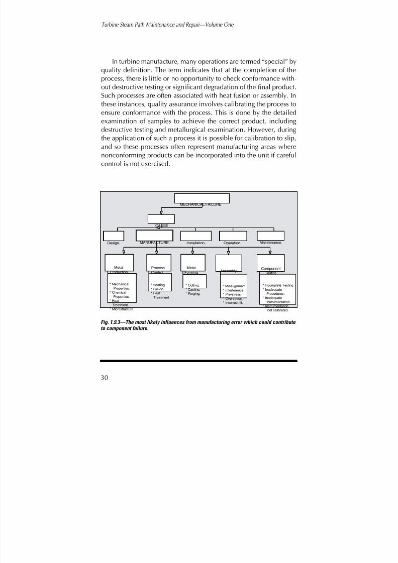
8/20/2019 mantenimiento de turbinas
http://slidepdf.com/reader/full/mantenimiento-de-turbinas 49/575
Turbine Steam Path Maintenance and Repair—Volume One
30
In turbine manufacture, many operations are termed “special” byquality definition. The term indicates that at the completion of theprocess, there is little or no opportunity to check conformance with-out destructive testing or significant degradation of the final product.Such processes are often associated with heat fusion or assembly. Inthese instances, quality assurance involves calibrating the process toensure conformance with the process. This is done by the detailedexamination of samples to achieve the correct product, including
destructive testing and metallurgical examination. However, duringthe application of such a process it is possible for calibration to slip,and so these processes often represent manufacturing areas wherenonconforming products can be incorporated into the unit if carefulcontrol is not exercised.
Figure 1.9.3
The most likely influences from manufacturing error which could contribute to component failure.
CAUSE
MECHANICAL FAILURE
Design. MANUFACTURE. Installation. Operation. Maintenance.
Process
Control
Metal
Forming Assembly. Metal
Production.
* Cutting.
* Casting.
* Forging.
* Heating.
* Fusion.
* Heat
Treatment.
* Misalignment
* Interference.
* Pre-stress.
* Overstress.
* Incorrect fit.
* Mechanical
Properties.
* Chemical
Properties.
* Heat
Treatment.
* Microstructure.
ComponentTesting
* Incomplete Testing
* Inadequate
Procedures.
* Inadequate
Instrumentation.
* Instrumentation
not calibrated.
Fig. 1.9.3—The most likely influences from manufacturing error which could contribute
to component failure.

8/20/2019 mantenimiento de turbinas
http://slidepdf.com/reader/full/mantenimiento-de-turbinas 50/575
Consideration of a Turbine Steam Path Maintenance Strategy
31
Poor quality installation. Assembly and installation on-site is acomplex operation that includes the installation of individual com-ponents and sub-assemblies. This should also be considered toinclude commissioning, which is normally an integral part of the tur-bine supply process. If these activities are not performed in a correct,controlled manner they will often result in poor operating character-istics and the imposition of undue stresses on the component parts of the unit. These additional strains can include residual stresses leading
to premature failure within the components of the unit if not detect-ed and corrected. Some possible causes of installation- and totalassembly requirement-initiated failures are shown in Figure 1.9.4.
Site assembly requires that multiple section units be aligned invertical and horizontal locations and all clearances are at designspecified values to achieve the correct relationship between the
Figure 1.9.4The most likely influences from poor installation which could contribute to component failure.
CAUSE
Operation. Maintenance.
Shop
ErectionShop
Testing
Field
ErectionStart up
* Incorrect assembly
and sub-assemblies.
* Incorrect fits in the
assembled
components.
* Incorrect component
alignment.
* The use of incorrect,
or inadequate procedures.
* Inadequate test
procedures.
* The use of poor testing
techniques.
* Failure to correct found
discrepancies.
* Failure to achieve
design specified
alignment
* Failure to achieve
clearances at
critical positions.
* The use of incorrect
procedures.
* Misapplication of
procedures.
* Inadequate testing and
setting of trips and
control mechanisms.
Design. Manufacture. INSTALLATION.
MECHANICAL FAILURE
Fig. 1.9.4—The most likely influences from poor installation which could contribute to component failure.

8/20/2019 mantenimiento de turbinas
http://slidepdf.com/reader/full/mantenimiento-de-turbinas 51/575
Turbine Steam Path Maintenance and Repair—Volume One
32
rotating and stationary components during operation. Failure toachieve the correct alignment will result in higher than expected lev-els of vibration and possibly the imposition of alternating stresses onthe normal operating levels predicted by design. Poor control of alignment can also result in operating “rubs” that have the potentialto degrade efficiency and reliability.
Control gear and instrumentation must also be installed and cal-ibrated to ensure required levels of control and protection.
Poor or incorrect operating practices. A common cause of com-ponent deterioration or failure is the application of incorrect operat-ing procedures, or violation of the operating parameters. This is par-ticularly relevant in temperature variations. In many instances the unitoperator may have little control over such variations and may have torespond to the requirements of the system controller so customerdemands can be met. However, such conditions required by the sys-tem controller must still be considered faulty operating procedures.
It is normal for the design engineer to place certain limitations orrestrictions on the manner in which the unit is operated. These limi-tations are not arbitrary, and are intended to minimize stresses in allforms to which the unit components are subjected. Operating out-side these limitations will consume the life of the elements and canlower the predicted life. The rate at which the unit or component lifeis consumed also has an effect on the unit reliability.
Figure 1.9.5 shows some of the operating actions that can resultin component failure, life consumption, or deterioration. It is clearthe operation of other system components can also influence thesteam turbine. The operator, therefore, has a responsibility to ensure,as far as possible, other pieces of equipment do not impact adverse-ly on the performance of the steam turbine.
Poor maintenance procedures. Steam turbine maintenance fallsinto two categories:
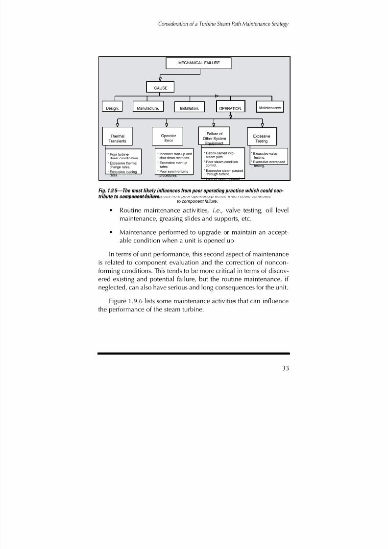
8/20/2019 mantenimiento de turbinas
http://slidepdf.com/reader/full/mantenimiento-de-turbinas 52/575
Consideration of a Turbine Steam Path Maintenance Strategy
33
• Routine maintenance activities, i.e., valve testing, oil levelmaintenance, greasing slides and supports, etc.
• Maintenance performed to upgrade or maintain an accept-able condition when a unit is opened up
In terms of unit performance, this second aspect of maintenanceis related to component evaluation and the correction of noncon-forming conditions. This tends to be more critical in terms of discov-ered existing and potential failure, but the routine maintenance, if neglected, can also have serious and long consequences for the unit.
Figure 1.9.6 lists some maintenance activities that can influencethe performance of the steam turbine.
Figure 1.9.5 The most likely influences from poor operating practice which could contribute
to component failure.
CAUSE
Design. Manufacture. Installation. OPERATION. Maintenance.
Thermal
Transients
OperatorError
Excessive
Testing
Failure of
Other System
Equipment
* Poor turbine-Boiler coordination.
* Excessive thermalchange rates.
* Excessive loadingrates.
* Incorrect start-up andshut down methods.
* Excessive start-uprates.
* Poor synchronizingprocedures.
* Debris carried intosteam path.
* Poor steam conditioncontrol.
* Excessive steam passedthrough turbine.
* Lack of system control.
* Excessive valvetesting.
* Excessive overspeedtesting.
MECHANICAL FAILURE
Fig. 1.9.5—The most likely influences from poor operating practice which could con- tribute to component failure.

8/20/2019 mantenimiento de turbinas
http://slidepdf.com/reader/full/mantenimiento-de-turbinas 53/575
Turbine Steam Path Maintenance and Repair—Volume One
34
The examination of a failure
Considering the causes listed above, when a failure or deteriorat-ing condition is found to exist, it is important to identify the actualcause and, to the greatest extent possible, establish if it was the result
of design, manufacture, installation, operation, or maintenance. Thiscan become a difficult and often impossible task. There are no rulesor guidelines that can be applied. It often takes considerable investi-gation to identify both the cause and the initiating condition.
Often, if the initiating condition can be identified (i.e., inferior orinadequate material, poor process control, overheating of the com-ponents, etc.), it becomes considerably easier to establish which of
the five causes discussed above is the initiating condition.
Figure 1.9.6 The most likely influences from poor maintenance procedures which could contribute
to component failure.
CAUSE
Design. Manufacture. Installation. Operation. MAINTENANCE.
NormalMaintenance
Activities
OutageDetermined
Maintenance.
Repair andRefurbishment
Activities
* Failure to undertakeRecommendedMaintenance.
* IncorrectMaintenanceProcedures.
* Use of incorrectmaterials andapproved substances.
* Failure to correct afound nonconformance.
* Correction by inadequate Procedure.
* Correction by inadequate methods.
* Use of unqualified skills to perform repairs.
* Use of incorrect tools toperform repairs.
* Misapplication ofprocedures.
MECHANICAL FAILURE
Fig. 1.9.6—The most likely influences from poor maintenance procedures which couldcontribute to component failure.

8/20/2019 mantenimiento de turbinas
http://slidepdf.com/reader/full/mantenimiento-de-turbinas 54/575
Consideration of a Turbine Steam Path Maintenance Strategy
35
The cause of a nonconforming situation within a unit—evenwhen the mechanism is well defined and agreed upon—is often acontentious matter among the parties involved in correcting it.
In fact, in some instances, it becomes impossible to isolate a sin-gle cause beyond a reasonable doubt. It should be remembered thatthe primary reason for identifying the cause is not to apportionblame (except in the case of new units or components where war-ranty considerations exist), but to allow the manufacturer and plantstaff to initiate corrective actions that will prevent or minimize thepossibility of its reoccurrence.
Figure 1.9.7 is a logic diagram for the investigation and identifi-cation of causes and mechanisms for a damaged or deterioratedcondition.
This investigative process is shown to comprise two phases. The
first might be termed a “field phase”—while all material and infor-mation is at the site, work is undertaken to allow the condition to becorrected and the unit returned to service. There are many occasionswhen this will suffice and no further investigation is required.
However, if this field phase does not identify the cause and/ormechanism, then the second is initiated—normally after the unit hasbeen returned to service. There are instances when a condition can-
not be corrected and restorative action taken until this “laboratoryphase” is complete—possibly after some redesign and/or correctivemanufacture has been undertaken. This need is determined by theextent and severity of the failure.
Initiating and driving mechanisms
When attempting to analyze a failure, it is necessary to identifythe cause as far as possible. It is also necessary to identify the mech-anisms involved in the failure. This determination can be difficult.For a well-designed and well-operated unit, the stress levels and
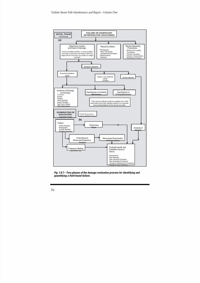
8/20/2019 mantenimiento de turbinas
http://slidepdf.com/reader/full/mantenimiento-de-turbinas 55/575
Turbine Steam Path Maintenance and Repair—Volume One
36
(b)
(a)
Figure 1.9.7 Two phases of the damage evaluation process for identifying and quantifying a field found failure.
FAILURE OR SIGNIFICANT DETERIORATION DISCOVERED
Record Condition.
* Photographs.
Macro and generalarrangement and location.
* Measurements
* Sketches.
Determine Locationand Extent of damage.
Is this an isolated condition, or is the condition
occurring in more than one location within the
stage and are more than one location or stagesinvolved?
Surface depositsDebris or any detached
pieces
available
Corrosion.
Erosion.
Fretting.Water Damage.
Impact Damage.
High Cycle Fatigue.
Other Mechanisms.
Sample Collection.
Evidence of Damageand Surface Hypothesize on Initiating
Mechanism
Hypothesize onDriving Mechanism
INITIAL PHASE
Field Phase).
EXAMINATION OR EVALUATION
Failure Samples
Photographs.Surface Samples.
Operating Records.
Collect:Preliminary
Visual
Finite ElementStress and Frequency
Analysis
Microscopic Examinationof failure surface.
Analysis ofdeposits.
Frequency Testingand Anal sis.
Evaluate results andEstablish Cause offailure.
Recommend:
New Materials.
New mounting Procedure.
New Operating Procedures.
Change to Maintenance Procedures.
Change of water chemistry.
Review OperatingProcedures.
* Starting and Loading
Procedures.
* Thermal Transients.* Vibration Characteristics.
* Maintenance Practice.
If Field Observations
cannot establish causes
There may be sufficient evidence available from a field
examination that further detailed analysis is not required,
and recommendations for the unit can be made.
(Laboratory Phase)
Examine Initiationpoint.
Fig. 1.9.7—Two phases of the damage evaluation process for identifying and quantifying a field found failure.

8/20/2019 mantenimiento de turbinas
http://slidepdf.com/reader/full/mantenimiento-de-turbinas 56/575
Consideration of a Turbine Steam Path Maintenance Strategy
37
operating procedures should guard the various components againstpremature failure. Therefore, when a failure or deteriorated condi-tion is found, it is important to identify the mechanisms producingthis condition.
In making this determination it is normally necessary to identifytwo separate mechanisms. The first is that which initiated the condi-tion—which can be any of a number, as discussed below. The sec-ond is the mechanism that is driving the condition, often to failure.In the majority of situations, this mechanism is high-cycle fatigue,ultimately producing material rupture at stress levels well belowthose able to produce failure if an initiating condition or fault hadnot been induced by some other stress-concentrating condition (i.e.,the initiating mechanism).
The mechanisms of damage and deteriorationThe mechanisms of failure are the normal deteriorating process-
es such as fatigue and corrosion, which can occur in the majority of mechanical components if the conditions are right. Many of thesemechanisms are relatively easy to recognize. They are known tooccur as a result of the environment in which components of the unitoperate and the loads to which they are subjected. In terms of thesteam turbine the major mechanisms are:
High-cycle fatigue (HCF). Possibly the most damaging effectspresent in the turbine steam path are those associated with HCF.HCF is a mechanism that is a primary or initiating cause of failure inmany components, both rotating and stationary. It is also the majordamaging mechanism that will drive damage initiated by some othermechanism, forcing the situation to propagate to destructive levels.
Cyclic effects (or impulses) are generated in the flowing steam dueto a number of effects (discussed in chapter 5). The frequency of theimpulse is dependent upon the nature and source of the excitation,

8/20/2019 mantenimiento de turbinas
http://slidepdf.com/reader/full/mantenimiento-de-turbinas 57/575
Turbine Steam Path Maintenance and Repair—Volume One
38
and the magnitude is dependent upon the flow characteristics at thatlocation in the flow path. (Table 5.10.1 of chapter 5 lists various excit-ing sources within the steam path.) It is not necessary for the impulsemagnitude to be high for failure to occur. Also, if the frequency of theimpulse is near one of the natural frequencies of the damaged com-ponent, it requires only a relatively low magnitude impulse to causefailure.
A typical surface showing the effects of HCF is shown in Figure1.9.8. The “beach” marks characteristic of HCF can be clearly seen.In fact, the true HCF surface shows a fine, uninterrupted crystallinestructure, and the final rupture is in the form of a tensile or torsionaloverload failure, depending upon the form and type of stress causingfinal separation. The beach marks are normally present and representtransient conditions causing a fracture arrest or change in the crackpropagation rate. This can be a massive progression of the crack at
the tip of its current position.
Fig. 1.9.8—The striations or beach marks on the vane of an L-1 blade, and the mating tip section recovered from the internals of the turbine.
T A P P S

8/20/2019 mantenimiento de turbinas
http://slidepdf.com/reader/full/mantenimiento-de-turbinas 58/575
Consideration of a Turbine Steam Path Maintenance Strategy
39
Section Harmonic Typical Sources
High Pressure • High per rev • Nozzle tolerance limits
Section • (40x) • Upstream wake degenera-
tion • Structural turbulence
Intermediate • Nozzle passing • Nozzle wakes
Pressure • frequency (NPF)
Section • 2 x NPF • Diaphragm harmonics
• 3 x NPF • Diaphragm harmonics
Low • One per rev • Relative displacement
Pressure • nozzles to blades
Section • 2 per rev • Diaphragm joints
• Multiple/rev • Structural supports
• in flow path
• Medium/rev • Diaphragm harmonics
• Aeroelastic disturbances
• High/rev • Nozzle turbulence
• harmonics• Upstream wake
• degeneration
• Structural turbulence
Table 1.9.1—Steam Path Exciting Forces
The true HCF surface has no indication of mechanical deforma-tion, and if a surface were to fail entirely by HCF, the mating surfaces
would “fit” together perfectly.
Low-cycle fatigue (LCF). Low-cycle fatigue is distinct from theHCF phenomena in several ways. These are best summarized as:
• the number of cycles required to cause failure are signifi-cantly less than for HCF—the time to failure being a functionof the magnitude of the stress levels
• the number of stress cycles to cause failure are significantlyless than for HCF. An arbitrary demarcation is often taken tobe 100,000 cycles. However, this is simply a convenient

8/20/2019 mantenimiento de turbinas
http://slidepdf.com/reader/full/mantenimiento-de-turbinas 59/575
Turbine Steam Path Maintenance and Repair—Volume One
40
means of definition. Surface appearance and other charac-teristics provide a better delineation between the two
• the individual stress levels developed at each cycle are nor-mally considerably higher with the low-cycle effects
• there is mechanical deformation at the failure surface, andfailure marks show individual evidence of rupture, i.e., thestresses are large enough to cause plastic deformation at the
leading edge of the crack
The most common forms of LCF failure are those attributed tothermal cycling, when large temperature changes occur causinglocalized thermal expansion or contraction of the material surface.These thermal movements introduce large internal constrainingforces within the material introducing stresses of a magnitude suffi-cient to initiate and drive to rupture.
Figure 1.9.9 shows a normal LCF crack that originated at a sharpcorner within a high temperature casing. Such cracks can berepaired normally by welding or by stitching.
Fig. 1.9.9—A low cycle fatigue crack in a high pressure casing. This crack originating at a point of high stress concentration adjacent to the nozzle plate.

8/20/2019 mantenimiento de turbinas
http://slidepdf.com/reader/full/mantenimiento-de-turbinas 60/575
Consideration of a Turbine Steam Path Maintenance Strategy
41
Creep deformation. Steels that are subjected to elevated temper-atures for extensive periods exhibit changes in their microstructure.This has a marked effect on the material creep characteristics. Underconditions of high tensile stress, failures are normally trans-granular.However, at elevated temperatures and with the application of ten-sile stress, it is common for inter-granular failure to occur due to theeffects of creep. Creep is a granular “slip” mechanism within thematerial that occurs at dislocations of the grain boundaries. This slip
causes a plastic distortion of the components that is not removedwhen the stress is removed from the component.
On high temperature stages there are instances in which creepdeformation causes plastic deformation of the steam path compo-nents. This is not a common type of mechanism, and occurs in onlythe highest temperature elements. It is often difficult to detect with-out the aid of detailed and repeated measurements. However, in
those instances where this phenomenon is present, it contributes tothe general degradation of a stage or component.
It is uncommon for elements to operate for periods of time afterthey go into the tertiary region of creep—and fail—as the damage isnormally obvious before this level of damage is reached. Figure1.9.10 shows the notch block in a high-temperature stage in whichthe centrifugal load of the blade is causing creep deformation of the
pin and wheel material. Such damage presents an increase of thegap between the closing block and wheel. This type of gap is com-mon but does not necessarily indicate that failure will occur. Thewidth of the gap should be monitored until a maximum stipulatedgap has been formed.
Solid-particle erosion (SPE). SPE is a damaging mechanismfound in many front-end stages of high-pressure and reheat sections.
SPE removes material from surfaces through a combination of goug-ing and the impact of solid particles of hard scale exfoliated fromboiler tubes and carried into the steam path.

8/20/2019 mantenimiento de turbinas
http://slidepdf.com/reader/full/mantenimiento-de-turbinas 61/575
Turbine Steam Path Maintenance and Repair—Volume One
42
As scale enters the steam path, it impacts on and removes mate-rial from the stationary and rotating blade elements, the sidewalls,and the coverbands. It is also capable of removing coverband tenonmaterial, thereby weakening the attachment of the coverband to theblades.
On stationary blade rows, the major effect is to remove materialfrom the vane discharge edge, causing thinning and an increase in
Fig. 1.9.10—The notch block from a high temperature stage
which has crept out radially under the influence of cen- trifugal loading.

8/20/2019 mantenimiento de turbinas
http://slidepdf.com/reader/full/mantenimiento-de-turbinas 62/575
Consideration of a Turbine Steam Path Maintenance Strategy
43
the stage discharge area and angle (Fig. 1.9.11). The sidewalls canalso suffer material removal, normally at the outer sidewall. The inletto the stationary blades can also be affected by the gouging action of the particles (Fig. 1.9.12).
On the rotating blades, material is removed from the inlet edge,modifying the vane section and inlet angle (Fig. 1.9.13) and canremove material from the discharge edges (Fig. 1.9.14). From a struc-tural consideration, a more insidious material loss comes from thepressure or concave face of the profile (Fig. 1.9.15). Such damageshould be looked for when damage of the form shown in Figure1.9.14 is evident. This is because many stages subject to this erosivephenomenon have an integral coverband. This material loss repre-sents an undercutting of the integral coverband that will weaken theouter section of the blade and modify its vibratory characteristics.
For stages without integral coverbands, there can be an undercuttingof the tenons.
Fig. 1.9.11—Solid particle erosion showing material loss from a fixed blade discharge edge. In this stage the material loss is from previously weld repaired elements, and the loss has been severe. This material loss modifies the total discharge area from the stage.
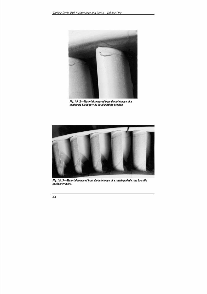
8/20/2019 mantenimiento de turbinas
http://slidepdf.com/reader/full/mantenimiento-de-turbinas 63/575
Turbine Steam Path Maintenance and Repair—Volume One
44
Fig. 1.9.12—Material removed from the inlet nose of astationary blade row by solid particle erosion.
Fig. 1.9.13—Material removed from the inlet edge of a rotating blade row by solidparticle erosion.

8/20/2019 mantenimiento de turbinas
http://slidepdf.com/reader/full/mantenimiento-de-turbinas 64/575
Consideration of a Turbine Steam Path Maintenance Strategy
45
Corrosive effects. The ingress of corrosive ions into the steampath is always potentially possible. These ions have the potential to
cause dramatic and expensive outages within the unit, and manystages of the turbine can be affected by this condition. However, themost seriously affected stages are usually those in which moistureforms after expansion of the working fluid into the moisture region.As this occurs, many of the corrosive ions precipitated from thesteam are deposited on the steam path surfaces and the depositedmoisture carries them into “hideouts” where they concentrate. Atthese locations they become aggressive when the correct environ-mental conditions occur.
Fig. 1.9.14—Material loss from the discharge edge of a rotating blade row by solid particle erosion.
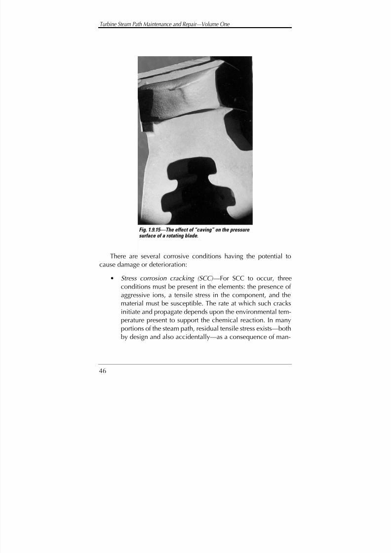
8/20/2019 mantenimiento de turbinas
http://slidepdf.com/reader/full/mantenimiento-de-turbinas 65/575
Turbine Steam Path Maintenance and Repair—Volume One
46
There are several corrosive conditions having the potential tocause damage or deterioration:
• Stress corrosion cracking (SCC) —For SCC to occur, threeconditions must be present in the elements: the presence of aggressive ions, a tensile stress in the component, and thematerial must be susceptible. The rate at which such cracksinitiate and propagate depends upon the environmental tem-
perature present to support the chemical reaction. In manyportions of the steam path, residual tensile stress exists—bothby design and also accidentally—as a consequence of man-
Fig. 1.9.15—The effect of “caving” on the pressure surface of a rotating blade.

8/20/2019 mantenimiento de turbinas
http://slidepdf.com/reader/full/mantenimiento-de-turbinas 66/575
Consideration of a Turbine Steam Path Maintenance Strategy
47
ufacture. At these locations SCC can readily occur. The rateat which corrosive cracks are generated and then propagatedepends upon the concentration of corrosive products andthe magnitude of the stress and local temperature
• Corrosive pitting —Figure 1.9.16 shows a rotor portion where“High-Lo” seal castellation occurred. An environment of geothermal steam with a high corrosive content has corrod-ed these
• Corrosion fatigue —Many components are subject to alter-nating stress of a magnitude that ultimately, fatigue con-tributes to its deterioration. If a corrosive element furthercontaminates the component, then the component’s abilityto resist failure is further impacted. Under these circum-stances, failure will occur at either lower stress levels or in ashorter period of time at the same stress. Figure 1.9.17 showsa crack emanating from a tie-wire hole, where the initiatingmechanism of failure was found to be corrosion fatigue
Fig. 1.9.16—Corrosive pitting on a rotor surface.

8/20/2019 mantenimiento de turbinas
http://slidepdf.com/reader/full/mantenimiento-de-turbinas 67/575
Turbine Steam Path Maintenance and Repair—Volume One
48
This latter form of failure is distinct from SCC in that the appliedstress is cyclic and the failure is a fatigue-type mechanism. Such fail-ures tend to initiate at those points where corrosive products canconcentrate and where a level of stress concentration causes highlocal tensile effects. Such cracks can be either trans-granular orinter-granular.
Moisture effects. Moisture forms in the working fluid due to con-densation from the expanding steam (see chapter 3). Water droplets
that form are transported through the steam path by the parentsteam. Some of these droplets are ultimately deposited on the com-ponent surfaces where they have the ability to flow across them and
Fig. 1.9.17—A crack initiating at the tie wire hole.
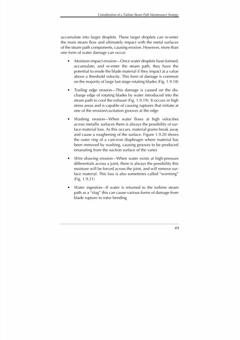
8/20/2019 mantenimiento de turbinas
http://slidepdf.com/reader/full/mantenimiento-de-turbinas 68/575
Consideration of a Turbine Steam Path Maintenance Strategy
49
accumulate into larger droplets. These larger droplets can re-enterthe main steam flow and ultimately impact with the metal surfacesof the steam path components, causing erosion. However, more thanone form of water damage can occur:
• Moisture-impact erosion—Once water droplets have formed,accumulate, and re-enter the steam path, they have thepotential to erode the blade material if they impact at a valueabove a threshold velocity. This form of damage is commonon the majority of large last-stage rotating blades (Fig. 1.9.18)
• Trailing edge erosion—This damage is caused on the dis-charge edge of rotating blades by water introduced into thesteam path to cool the exhaust (Fig. 1.9.19). It occurs in highstress areas and is capable of causing ruptures that initiate atone of the erosion/cavitation grooves at the edge
• Washing erosion—When water flows at high velocitiesacross metallic surfaces there is always the possibility of sur-face material loss. As this occurs, material grains break awayand cause a roughening of the surface. Figure 1.9.20 showsthe outer ring of a cast-iron diaphragm where material hasbeen removed by washing, causing grooves to be producedemanating from the suction surface of the vanes
• Wire drawing erosion—When water exists at high-pressuredifferentials across a joint, there is always the possibility thismoisture will be forced across the joint, and will remove sur-face material. This loss is also sometimes called “worming”(Fig. 1.9.21)
• Water ingestion—If water is returned to the turbine steampath as a “slug” this can cause various forms of damage from
blade rupture to rotor bending
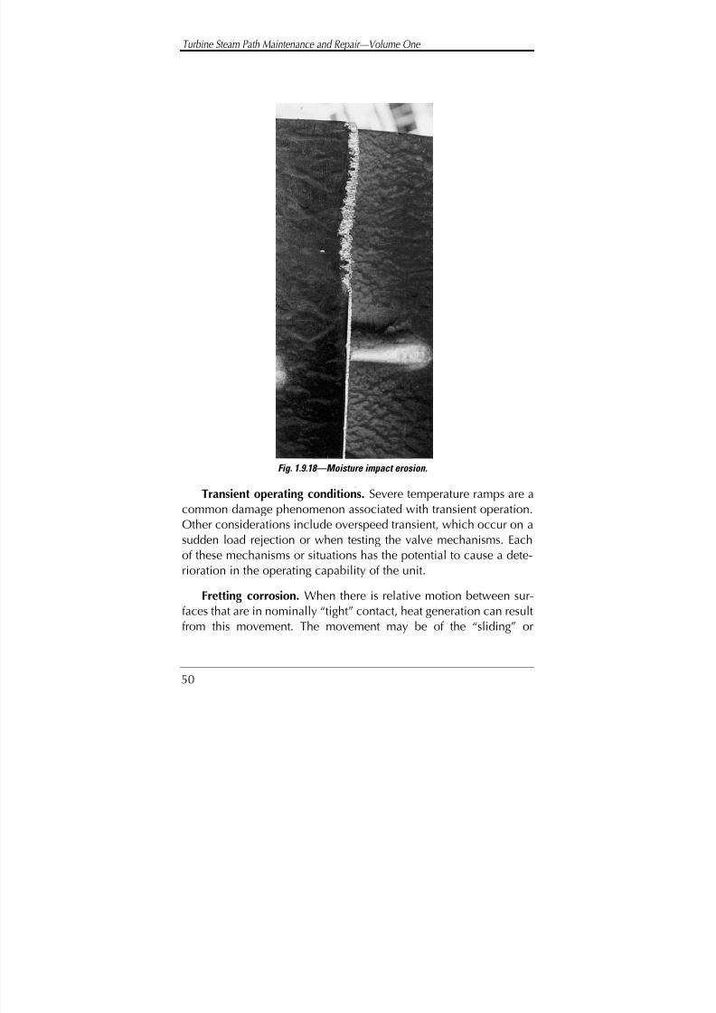
8/20/2019 mantenimiento de turbinas
http://slidepdf.com/reader/full/mantenimiento-de-turbinas 69/575
Turbine Steam Path Maintenance and Repair—Volume One
50
Transient operating conditions. Severe temperature ramps are acommon damage phenomenon associated with transient operation.Other considerations include overspeed transient, which occur on asudden load rejection or when testing the valve mechanisms. Eachof these mechanisms or situations has the potential to cause a dete-rioration in the operating capability of the unit.
Fretting corrosion. When there is relative motion between sur-faces that are in nominally “tight” contact, heat generation can resultfrom this movement. The movement may be of the “sliding” or
Fig. 1.9.18—Moisture impact erosion.

8/20/2019 mantenimiento de turbinas
http://slidepdf.com/reader/full/mantenimiento-de-turbinas 70/575
Consideration of a Turbine Steam Path Maintenance Strategy
51
“impact” type. In either case there is a generation of excessive heatthat removes surface material by causing localized oxidation. Thematerial removed has the characteristic red “rust” appearance.
Fig. 1.9.19—Trailing edge erosion occurring on the last stage blades.
Fig. 1.9.20—Washing erosion on the outer ring of a cast iron diaphragm.

8/20/2019 mantenimiento de turbinas
http://slidepdf.com/reader/full/mantenimiento-de-turbinas 71/575
Turbine Steam Path Maintenance and Repair—Volume One
52
COMPONENT SUSCEPTIBILITYFOR DETERIORATION
Should either the critical fixed or rotating components within thesteam turbine sustain damage, it could be sufficient to force the unitfrom service. Such damage can be caused by various mechanisms
associated with operating phenomena resulting from the characteris-tics of the working fluid, its pressure, temperature, moisture content,and possible rate of change during operation (these were discussed
Fig. 1.9.21—Worming erosion on the half joint of a diaphragm.
8/20/2019 mantenimiento de turbinas
http://slidepdf.com/reader/full/mantenimiento-de-turbinas 72/575
Consideration of a Turbine Steam Path Maintenance Strategy
53
in the previous section). Deterioration can also be related to thestress levels within the components, or the result of matter carriedinto the unit from the boiler or other parts of the system. Problems of deterioration can also be the consequence of defects in the manu-facture of the component.
In terms of the level of damage or deterioration with which themaintenance staff should be concerned—and possibly be monitor-ing—the following categories of “deterioration potential or suscepti-bility” can be ascribed to the various locations and componentswithin the steam path. While not exhaustive, they will provide somegeneral indication.
High susceptibility
Typically, these components include the last (L-0) stage rotating
blades and many L-1 or L-2 stages. These longer blades are tuned,and the last stage blades are subject to variable pressure ratios anddamage as a consequence of their interaction with the moisture pres-ent in the steam. This category would also include the high temper-ature stages of the high pressure and reheat sections that operate onsteam returned from the boiler. In these stages, exfoliated scale maybe carried in with the steam, causing stationary and rotating bladevane material loss. If the first stage of the high-pressure section is also
subject to the effects of partial arc admission, that can also causehigh impulse loads on the stationary and rotating blades, possiblyleading to high-cycle fatigue failures.
Wheels shrunk onto a central spindle can have a high potentialfor damage due to corrosive action. This—in terms of serious dam-age—can be avoided to some extent by the stringent control of waterquality and careful examination at outages.

8/20/2019 mantenimiento de turbinas
http://slidepdf.com/reader/full/mantenimiento-de-turbinas 73/575
Turbine Steam Path Maintenance and Repair—Volume One
54
Intermediate susceptibility
Typically, these components include those subject to corrosiveattack, such as the last minus one (L-1) stage in the low-pressure sec-tion. Depending upon the pressure distribution, it could also includethe last minus two (L-2) stage. This group also includes stages with adrilled hole in the vane for the admission of tie wires. The secondand third stages after admission or return of hot steam can also beincluded because of degraded material mechanical properties at
high temperatures. Because pressure loads on the various stage com-ponents can be high, creep deformation is a consideration. The pos-sibility still exists with these front-end stages that hard scale from theboiler will cause an erosive material loss.
The diaphragms of the high temperature stages can be subject tocreep, and rubbing should be considered as a potential. Nozzleboxes in the high pressure section can be a cause for concern due to
solid-particle erosion and possibly other damage resulting from tem-perature transients and debris carryover from the boiler, particularlyafter boiler repairs.
Low susceptibility
This category includes all other components and stages in the
unit. The blade rows operate at substantially constant pressure ratios.Operating temperatures are normally below the threshold tempera-ture where material properties are reduced significantly, so compo-nents are not normally subject to creep deformation.
The rotor wheels, in many stages—particularly if there are pres-sure balance holes—have a potential to cause problems, and filletradii can eventually be the initiation point of low-cycle fatigue
cracks. In wet stages, these wheels can be subject to moisture-impacterosion under certain operating conditions, although the thresholdvelocity at which such erosion normally occurs has not beenachieved.
8/20/2019 mantenimiento de turbinas
http://slidepdf.com/reader/full/mantenimiento-de-turbinas 74/575
Consideration of a Turbine Steam Path Maintenance Strategy
55
Categorization
In categorizing components, it must be remembered that manyunits appear to have characteristics which make certain stages andcomponents within those stages more susceptible to damage anddeterioration. Therefore, categorization as given above should beconsidered as only a guide, and should not be interpreted to meanthe “low susceptibility” elements will not suffer damage until afterthe ‘high’ and ‘intermediate susceptibility’ elements have been
affected. Most owners will be aware of “rogue” stages and compo-nents that appear to fail with monotonous regularity in an otherwiseacceptable unit.
While some elements may have a high susceptibility to failure ordeterioration, it is possible that in the event of failure, these can beremoved and the unit will continue to operate. Conversely, it is pos-sible that low susceptibility elements must be replaced or refur-
bished when they do deteriorate, before the unit can be returned toservice. The susceptibility level does not designate or indicate theability of the component to force the unit from service for extendedperiods; rather, it reflects only the component’s propensity to dam-age and/or deterioration.
Owners will often identify potential problem areas in their unitsat the first (warranty) inspection. At that time, the manufacturer will
make a detailed examination of the unit and be able to identify tothe operators any area or areas that have shown deterioration levelsabove the “norm” for the units. The owner should then decide tomonitor these components, make a record of the existence of anydamage present, and define or record the extent in some manner.The owner may also elect to carry replacement parts as inventoryspares in the event they are required.
Monitoring efforts, when undertaken, should be concentrated onthe most susceptible locations and components. A monitoring system

8/20/2019 mantenimiento de turbinas
http://slidepdf.com/reader/full/mantenimiento-de-turbinas 75/575
Turbine Steam Path Maintenance and Repair—Volume One
56
can be established in conjunction with the unit manufacturer, who isnormally interested in such information for future designs.
Steam seals are one series of components of the steam path thatdo not have a significant susceptibility to cause a forced outage—though their performance can influence the operation of the unitconsiderably. High leakage rates in seals will cause extensive lossesto an owner in terms of higher fuel costs. It is generally prudent tohave replacement seals or gland rings available at each outage, andthe owner should know the limit at which deterioration (increasedleakage area) can no longer be accepted. The owner should be pre-pared to replace worn seals whenever a unit is available.
Many seals are produced as an integral part of another compo-nent. These cannot be easily or economically replaced. However,refurbishment actions can often be taken to improve their effective-ness without major replacement. Recent advances in repair andrefurbishment technology have added considerably to the ability of owners to refurbish existing components. This is particularly true forrotating blades (see chapter 8). Such refurbishment techniques canoften reduce maintenance costs significantly, and return the ele-ments to a fully acceptable mechanical condition within periods of time sufficient to support a normal maintenance outage.
While these refurbishment techniques are often able to returnsteam path elements to an acceptable condition, it may be necessaryto plan that such refurbishment is undertaken during periods of low-load demand (when unit output is not required or can be replacedfrom other sources and the unit can be made available for this work).If the refurbishment process is protracted, the resulting extended out-age, and the cost of purchasing replacement energy may more thanoffset any potential savings from refurbishment. Some refurbishment
techniques may be undertaken on-site and in place; others mayrequire the components be removed from the unit.

8/20/2019 mantenimiento de turbinas
http://slidepdf.com/reader/full/mantenimiento-de-turbinas 76/575
Consideration of a Turbine Steam Path Maintenance Strategy
57
INSTANTANEOUSDAMAGE OR FAILURE
An instantaneous failure is one that occurs when the owner hasno prior or minimal warning from a previous outage or observations,to the extent preventative action could be taken. In such cases, a sig-nificant failure is suspected from a change in operating characteris-
tics and a unit is opened for inspection—and the failure is con-firmed. At this point, the owner must make some determinationregarding the actions required to return the unit to an acceptablecondition, and then to service.
The instantaneous failure can be severe enough that refurbish-ment actions required are self-evident. Other failures or damageleave a degree of options available. In some instances the unit can be
returned to service for an acceptable period with partial repair under-taken. A final decision concerning required corrective actions may beinfluenced by diverse factors such as the amount of reserve generat-ing capacity on the system and the cost and availability of replace-ment or incremental power from other sources. The owner is alsoinfluenced by the extent to which replacement parts are available.
The ability to refurbish the damage within an acceptable time
must be considered, as must the cost and potential of success likelyto be achieved. The ultimate selection of corrective action will mostprobably involve at least the following factors:
Parts. Are replacement parts available from inventory? How longwould it take for such parts to be manufactured and installed? Canthe existing components be repaired or refurbished?
Power. Can the unit be operated with the failed elements
removed? What is the level of power lost, and what effect will thishave on unit heat rate and availability? Will loading limitations berequired to protect the remainder of the unit? If the unit is operated

8/20/2019 mantenimiento de turbinas
http://slidepdf.com/reader/full/mantenimiento-de-turbinas 77/575
Turbine Steam Path Maintenance and Repair—Volume One
58
without the failed components, will the steam conditions to the unitneed to be reduced, or will the unit be load limited?
Time. Will such refurbishment be less expensive than replace-ment, in terms of both initial cost, and the time to complete thework? What are the possible effects on unit availability?
The effect of a major component failure or deterioration con-cerns any owner. The owner will normally suffer a financial penalty
associated with such damage, through the cost of rectifying the situ-ation and/or additional generating costs during the unit’s unavail-ability. It is therefore necessary, in such circumstances, to determinethe most cost effective method of correcting the situation and pre-venting reoccurrences.
Often when new parts are installed after some form of failure,possibly the removed parts can be refurbished and carried as inven-
tory spares. This would allow a similar situation in the future to bedealt with in a more rational and expeditious manner. This is partic-ularly so if the components are prone to failure, or the unit is one of a multi-unit installation. The owner of a unit that has suffered someform of damage or failure should always consider this approach.
It is not possible to formulate any rules to assist in decision-mak-ing related to instantaneous or sudden deterioration. This damage is
only detectable from a change in the mode of operation of the unit,or its presence is determined at maintenance inspections when thesteam path is exposed. At the time damage is found, the owners mustdetermine the most expedient course of action. Such a determina-tion may be to replace the elements or to undertake refurbishment,should this be possible. The logic for such an evaluation indicatesthe analysis and decisions required to establish a repair procedure(Fig. 1.11.1).
Often circumstances of instantaneous failure or damage meaninsufficient time to make extensive plans without extending the outage,

8/20/2019 mantenimiento de turbinas
http://slidepdf.com/reader/full/mantenimiento-de-turbinas 78/575
Consideration of a Turbine Steam Path Maintenance Strategy
59
and the owner is forced into making a decision based on the mostexpeditious course at that time. In the long term this may not be themost suitable for rectifying the condition of the unit, and if doubtexists, a decision and action plan should be delayed until a more favor-able corrective action is possible.
FACTORS CONTRIBUTING TOGRADUAL DETERIORATION
A gradual deterioration is one that occurs due to some mecha-nism slowly lowering the performance potential of the unit. Such asituation can be monitored from station instrumentation or is a con-
Figure 1.11.1The evaluation of a failure and the considerations required
to arrive at an acceptable solution.
Can temporary repairs be
undertaken?
Are replacement
parts required?
Can the unit continue to operateif these components
are removed?
Have other portions of the unitsuffered consequential damage?
How critical is this unitto system security?
CORRECTIVE ACTIONDECISION
INSTANTANEOUS DAMAGE,UNIT FORCED FROM
SERVICE.
Is refurbishmentan option?
Are replacement
parts available?
What are the costsinvolved in each
option?
What is the timeframe for completing
each option?
Fig. 1.11.1—The evaluation of a failure and the considerations required to arrive at an acceptable solution.

8/20/2019 mantenimiento de turbinas
http://slidepdf.com/reader/full/mantenimiento-de-turbinas 79/575
Turbine Steam Path Maintenance and Repair—Volume One
60
dition measured and noted at planned outages. It is also a conditionthat allows monitoring so acceptable corrective action can be deter-mined and planned corrections made before the condition reaches alevel the unit is unable to operate in either a safe or efficient manner.
There are principal and various mechanisms that can contributeto gradual deterioration—all possibly leading to failure:
• the operating environment within the unit
• stress levels
• material properties
• chemical contamination within the working fluid
• carry-over from other parts of the system
Here a brief survey of these factors will be considered.
Operating environment considerations
The steam path is designed to operate and achieve its outputunder stipulated steam conditions. The flow quantity required for aspecific output—the initial, reheat, and exhaust steam conditions—dictate stage geometry, construction materials, and design details.
System economics tend to dictate unit and cycle configuration.
While steam temperatures and pressures at operational speedmay introduce high levels of stress on components under normaloperating conditions, modern design technology can help ensurethese will not induce failure if the components are correctlydesigned. Under normal circumstances these are not factors thatwould cause elements to deteriorate or fail.
There are, however, instances where transient conditions (partic-ularly those of initial and reheat temperature) will induce high ther-
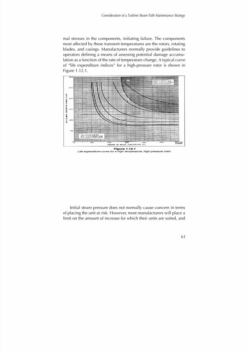
8/20/2019 mantenimiento de turbinas
http://slidepdf.com/reader/full/mantenimiento-de-turbinas 80/575
Consideration of a Turbine Steam Path Maintenance Strategy
61
mal stresses in the components, initiating failure. The componentsmost affected by these transient temperatures are the rotors, rotatingblades, and casings. Manufacturers normally provide guidelines tooperators defining a means of assessing potential damage accumu-lation as a function of the rate of temperature change. A typical curveof “life expenditure indices” for a high-pressure rotor is shown inFigure 1.12.1.
Initial steam pressure does not normally cause concern in termsof placing the unit at risk. However, most manufacturers will place alimit on the amount of increase for which their units are suited, and
SHADED AREA ISBORE STRESS LIMIT(NOT TO BE ENTEREDDURING INCREASES)
VALUES ON CURVESARE LIFE EXPENDITUREIN PERCENT PER CYCLE
Fig. 1.12.1—Life expenditure curve for a high temperature, high pressure rotor.
8/20/2019 mantenimiento de turbinas
http://slidepdf.com/reader/full/mantenimiento-de-turbinas 81/575
Turbine Steam Path Maintenance and Repair—Volume One
62
the number of hours of operation at these higher pressures. A pres-sure limit is normally stated as a percentage of the initial designvalue. Such a condition is generally of more concern in industrialinstallations where other sources of steam may become available.Under these conditions if applied without a full evaluation of theunit (and possible steam path modification), it could induce failuredue to one of several mechanisms.
For condensing units, minimum pressure must be maintained inthe condenser. The last stage blades of large utility units are a vari-able pressure ratio element (this ratio also varies with radial height).If the exhaust pressure is raised too high (in excess of 6” Hg, or inch-es of mercury), there is a possibility of inducing “flutter” type vibra-tions within the L-0 blades. There is also a possibility of deteriorationcaused by re-circulation through the lower vane sections of the dis-charging steam. This could occur because of the reduction in volu-
metric flow. Frictional heating of these last stage blades will cause achange in their operating temperature, and therefore could modifytheir vibration characteristics, which are temperature sensitive.
The one environmental effect that causes some level of deteriora-tion in most condensing units is moisture-impact erosion. However,in a well-designed unit, this type of damage should not be an impe-tus to change blades. In fact, few units suffer material loss and dete-
rioration to the extent blades cannot operate for 30 years. It is possi-ble that towards the end of this period, there could be a significantdeterioration in stage efficiency, but this is not a consideration of forced outage. At this time a unit normally operates at lower load fac-tors and is not as important to the security of the power system.
More problems are induced by the methods of shield attach-ment, which is a process involving the use of heat. It can expose the
blade material to the effects of heating cycles.

8/20/2019 mantenimiento de turbinas
http://slidepdf.com/reader/full/mantenimiento-de-turbinas 82/575
Consideration of a Turbine Steam Path Maintenance Strategy
63
Stress level considerations
Stresses are induced in the unit during normal operation due tothe steam environment, the effects of centrifugal loading, and thebending loads induced by the expanding steam.
As force develops on the blade rows, it is transmitted through therotor to the generator or mechanical device that the turbine drives,causing torque in the shaft. Stresses in the stationary portions are of
considerably less magnitude than those in the rotating components.In general, stationary components do not fail due to high-level stress,but there are instances in which stationary blades can suffer highvibratory loads and fail. Also, parts affected by creep will occasion-ally deflect axially to an unacceptable level.
The dangerous levels of stress induced in the rotating portions of the unit are most often those caused by stress concentration—a func-
tion of the geometry of the components. During the design phase, itis normal to evaluate the effect of stress, and modern design meth-ods are fully capable of determining even the most complex forms.Unfortunately, design conditions may not be maintained for longperiods. There are many regions of the rotating component wherestress concentration can be the result of mechanical damage, whereimpact or other types of deformations are produced as the result of operation. Such deformations should be looked for and some evalu-
ation made of their possible consequences. Non-destructive exami-nation should be undertaken of such discontinuities when they arefound.
Pressure impulses generated in the steam path have the potentialto amplify the dynamic loading applied to the various components.The design process attempts to recognize, predict, and quantify thesepotential effects, minimizing their damage-causing potential. How-
ever, they continue to occur and units are often forced from serviceas a consequence of their presence.
8/20/2019 mantenimiento de turbinas
http://slidepdf.com/reader/full/mantenimiento-de-turbinas 83/575
Turbine Steam Path Maintenance and Repair—Volume One
64
Material property considerations
For each component comprising the steam turbine, materials areselected and their properties evaluated for suitability. Materials areselected to help ensure the unit will operate for its entire life with theminimum probability of failure or need for replacement, if operatedto design specification. There are, however, some components con-sidered consumable, and it is the intention of design that these willbe replaced as required by the user.
The designers of steam turbines evaluate materials and establishthe variation of long life properties at various required temperatures.During the design phase the components are selected and dimen-sioned to achieve an acceptable “factor of safety” at the predictedstress levels and local environmental temperature.
To ensure that materials meet their design specified require-
ments, the manufacturer stipulates chemical composition, materialproperties, method of manufacture, heat treatment, grain structure,and level of non-metallic inclusions—all of which could affect lifeand performance. When the materials are received from the suppli-er, and before use, the manufacturer will evaluate them. The manu-facturer should not knowingly use any that do not meet the stipulat-ed requirements.
All high temperature components (above 900°F) and many oper-ating at high stress levels are particularly susceptible to variations of material properties. These components in particular should be eval-uated in detail and not produced from any material that does notmeet the highest standards as specified by design.
One aspect of material suitability that should be considered ismany material properties, especially at high temperatures, are nor-
mally determined from short time test data. If the material is of a newdesign, there could be some small margin of error in the stated val-ues. A manufacturer will normally allow for this possibility as a fac-tor of safety in the design.

8/20/2019 mantenimiento de turbinas
http://slidepdf.com/reader/full/mantenimiento-de-turbinas 84/575
Consideration of a Turbine Steam Path Maintenance Strategy
65
A designer’s additional concern for components designated forhigh temperature operation is that material properties in these envi-ronments—operating at high stress levels—can deteriorate withtime. This is an acknowledged fact and many components must haveeither an adequate factor of safety to prevent significant deterioration(blades), or be classified as a consumable (studs and nuts).
Considerations of chemical contaminationThere are two aspects of chemical contamination that need to be
considered:
• Possible deposits of compounds on steam path componentsthat will lower the efficiency of expansion and thereforeintroduce extra aerodynamic losses within the unit. This isundesirable in terms of operating cost, but is not an effect
that will lead to mechanical deterioration. It should be a partof each normal maintenance outage to remove thesedeposits by some suitable cleaning procedure
• Contaminants could gain access within the total thermalcycle and form corrosive compounds. These compounds canbe carried over from the boiler and other portions of thecycle, and will eventually be deposited on some steam path
components. Once deposited in the steam path, they will, atsome locations, be the constituents of failure in the unit—anaggressive chemical compound, tensile stress, and an elevat-ed temperature. These contaminants can react with con-struction materials and could eventually lead to mechanicalfailure, forcing the unit from service
8/20/2019 mantenimiento de turbinas
http://slidepdf.com/reader/full/mantenimiento-de-turbinas 85/575
Turbine Steam Path Maintenance and Repair—Volume One
66
Considerations of “carry-over”from other portions of the system
There are two types of carry-over into the turbine that need to beconsidered:
• The possibility of metallic or other solid debris carry-overfrom other parts of the system. This is concerned principallywith the flow of solid particles, such as a weld bead from the
boiler. This is normally most severe during initial start up,commissioning, or during early stages of operation. Duringthese periods it is common to use a fine mesh screen over themain and intermediate valves. Also, after some years of oper-ation, hard oxide scale exfoliated from boiler tubes will enterthe unit and cause solid-particle erosion (Figure 4.3.3 inchapter 4 shows a fine mesh screen with contained weldbead)
• There is also the possibility at any time during operation forwater to collect in a pipe above a choked drain. Under certaincircumstances, this water can be carried over into the unit. Theextent to which this will cause damage depends upon thequantity of water in the line, the manner of its entry to thesteam path, and the extent and duration of the ingestion
MONITORING DAMAGEAND DETERIORATION
There are certain types of damage or deterioration that, when
they occur, may not force a unit from service immediately but couldhave a long-term effect on availability. These are recognized as grad-ual deteriorating mechanisms. When such gradual deterioration is

8/20/2019 mantenimiento de turbinas
http://slidepdf.com/reader/full/mantenimiento-de-turbinas 86/575
Consideration of a Turbine Steam Path Maintenance Strategy
67
detected, it is often necessary and expedient to return the unit toservice. This represents a situation under which the operator can,and often should, initiate some form of monitoring programdesigned to establish the deterioration rate. If necessary, correctiveaction can be planned for a future outage. There are some forms of deterioration that can be accepted indefinitely, but this is usuallydone at some loss in unit efficiency.
One of the most complex and potentially controversial decisionsthe maintenance staff will be required to make when responsible forsteam turbine operation and performance is: “At what stage in their operating life has the condition of the components of the turbine steam path deteriorated to the extent corrective action must be taken––either to restore the efficiency to an acceptable level or to prevent failure which would force the unit from service”?
The factors that must be considered when damage is found, andthe decisions—possibly backed by financial evaluations—includethe following:
• Does the situation require immediate action to correct thisdeterioration, or can the unit continue to operate at accept-able levels of performance (efficiency and reliability) withthe damage it has sustained?
• If corrective action is considered necessary, is it appropriateto replace the components with new, or can existing ele-ments be refurbished? If refurbishment is considered ade-quate, can the work be undertaken on-site and in place, ormust the components be removed from the unit?
Since the mid ‘60s, vibration signature analysis has provided anindication of the overall condition of a unit, and regular monitoring
has allowed owners to detect and possibly identify pending prob-lems. However, signature analysis provides evidence of change inoperating characteristics once they have deteriorated to a point
8/20/2019 mantenimiento de turbinas
http://slidepdf.com/reader/full/mantenimiento-de-turbinas 87/575
Turbine Steam Path Maintenance and Repair—Volume One
68
where possibly significant damage has occurred. Decisions relatedto the timing of corrective action and outages are made easier if thecondition of specific components, with a known potential to deteri-orate, are monitored at regular inspections and their deteriorationrate established.
A suitable method of monitoring, and one that can be conduct-ed by plant operators without the use of any expensive equipment,is to examine the unit when it becomes available at regular mainte-nance inspections. At that time, the unit should be examined for evi-dence of abnormal or excessive deterioration.
The condition of the components should be quantified andrecorded through measurement, castings, and photographs. It isunfortunate, but with few exceptions it is not possible to make anexamination at other than periodic inspection outages. This meansthe steam path may only be available for detailed examination on anormal outage cycle. Because of this, it becomes necessary to exam-ine components in detail at these outages, note the extent of all dam-age or deterioration, refurbish to the extent possible, and then planto have replacement parts available for installation at subsequentoutages.
Any component of the steam path that deteriorates can be sub- ject to two levels (or rates) of deterioration. First is that which occurssuddenly, possibly instantaneously, as the result of some transientcondition or other phenomena of operation. These phenomena caninclude the failure of an upstream component that causes conse-quential damage, or the ingestion of large quantities of water. Suchdamage is normally severe and may give little or no warning of itspending occurrence. Therefore, little or no indication is offered thatthe unit should be shut down prior to the damage. After the damage
has occurred (and depending upon its severity), there may be a smallincrease in the vibration level or minor change in other operatingcharacteristics to provide evidence of its occurrence. Therefore, the

8/20/2019 mantenimiento de turbinas
http://slidepdf.com/reader/full/mantenimiento-de-turbinas 88/575
Consideration of a Turbine Steam Path Maintenance Strategy
69
damage may not be detected for some period, during which time thecondition could deteriorate further.
The second level of deterioration is that which occurs as a grad-ual effect, such as the growth of a crack or component material lossdue to some form of erosion. This second level of deterioration—thegradual worsening of the component condition—will often allow theowner to select and plan his remedial actions, and to make replace-ment parts and services available to meet an outage schedule. Sucha refurbishment outage may require, however, that a normal mainte-nance period be extended to allow satisfactory reconditioning.
The following sections consider various causes of gradual deteri-oration and, where possible, provide some guidelines that will assistoperators in determining the extent to which components need to bereplaced or refurbished. Unfortunately, there are no general rulesthat apply to any set of damage conditions. Obviously, the most sat-isfactory method is to replace or refurbish components when dam-age is first noted. However, this is not only expensive in terms of thereplacement cost, but could require an extended waiting period forsuch parts to be delivered or reconditioned. Normally, a plant’s out-age plans do not support such a delayed decision. There areinstances when damage can be accepted and monitored but thispossibility must be evaluated in each case.
The mechanism of gradual deterioration
Those principal and various mechanisms that can contribute togradual deterioration (possibly leading to failure) are considered inthe previous section Factors Contributing to Gradual Deterioration.When damage due to these forms of deterioration is found, it is rec-ommended that the condition be monitored so corrective action can
be taken before the unit is forced from service.

8/20/2019 mantenimiento de turbinas
http://slidepdf.com/reader/full/mantenimiento-de-turbinas 89/575
Turbine Steam Path Maintenance and Repair—Volume One
70
Monitoring techniques for gradual deterioration
There are certain types of damage or deterioration which, whenthey occur, may not force a unit from service immediately—butcould have a long-term effect on unit performance. When gradualdeterioration is initially detected, it is normally necessary and expe-dient to return the unit to service. This represents a situation bywhich the owner can (and often should) initiate some form of mon-itoring program to determine the deterioration rate. If necessary, cor-
rective action can be planned for some future outage. Some forms of deterioration can be accepted indefinitely, but this offers the possi-bility of a loss in unit efficiency.
This section uses examples to discuss typical monitoring tech-niques that can be applied to portions of the steam path compo-nents. They provide guidance of methods suitable for operators touse in establishing the rate of deterioration within the unit. They also
provide, where possible, some guidance when conditions are dete-riorating to an unacceptable level and corrective action should beconsidered.
In providing this guidance it must be remembered each unit isunique and represents a different set of parameters. Judgment is verymuch dependent upon the mode in which a unit is operated. Also,the owners’ previous experience is often a good indication as to the
danger posed by any situation. With these provisos, then, the follow-ing observations and situations should be considered as a guide, sub- ject to calibration from system, unit, and manufacturer experience.
Moisture-impact erosion. In general, moisture-impact erosionwill not by itself cause sufficient material loss that a blade will needto be replaced. Damage and material loss that occur in the outerportions of the blade vane should not impact upon element reliabil-
ity. This is true to the extent the erosion occurs on the inlet edge suc-tion face.
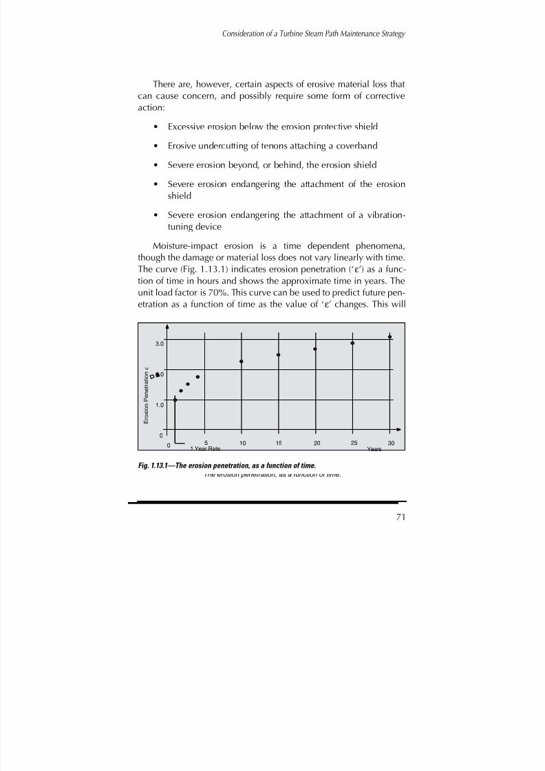
8/20/2019 mantenimiento de turbinas
http://slidepdf.com/reader/full/mantenimiento-de-turbinas 90/575
Consideration of a Turbine Steam Path Maintenance Strategy
71
There are, however, certain aspects of erosive material loss thatcan cause concern, and possibly require some form of correctiveaction:
• Excessive erosion below the erosion protective shield
• Erosive undercutting of tenons attaching a coverband
• Severe erosion beyond, or behind, the erosion shield
• Severe erosion endangering the attachment of the erosionshield
• Severe erosion endangering the attachment of a vibration-tuning device
Moisture-impact erosion is a time dependent phenomena,though the damage or material loss does not vary linearly with time.
The curve (Fig. 1.13.1) indicates erosion penetration (‘ε’) as a func-tion of time in hours and shows the approximate time in years. Theunit load factor is 70%. This curve can be used to predict future pen-etration as a function of time as the value of ‘ε’ changes. This will
Figure 1.13.1The erosion penetration, as a function of time.
5 10 15 20 25 300
1.0
2.0
3.0
0
E r o s i o n
P e n e t r a t i o n
1 Year Rate. Years
ε
Fig. 1.13.1—The erosion penetration, as a function of time.

8/20/2019 mantenimiento de turbinas
http://slidepdf.com/reader/full/mantenimiento-de-turbinas 91/575
Turbine Steam Path Maintenance and Repair—Volume One
72
allow some estimation of further damage that could occur. (This rela-tionship between penetration ‘ε’ and time is considered in greaterdetail in chapter 3.)
Localized or secondary erosion can be examined and its possi-ble effects estimated from the dimensional changes this produces onthe blade. Blades subject to moisture-impact erosion are also ele-ments that are tuned. These elements normally have high stress lev-els and their frequencies can be sensitive to changes in blade sec-tion. Figure 1.13.2 shows a blade row that has suffered some smalllevel of local secondary erosion that removed a greater amount of material at one specific location.
Fig. 1.13.2—Exhaust blades showing the variation of erosionpenetration in the outer flow sections.

8/20/2019 mantenimiento de turbinas
http://slidepdf.com/reader/full/mantenimiento-de-turbinas 92/575
Consideration of a Turbine Steam Path Maintenance Strategy
73
An example of monitoring the last-stage blades of a unit with pre-dicted heavy erosion is shown in Figure 1.13.3. Here the mean val-ues of erosion in the outer section is shown for the turbine end ‘A’ andthe generator end ‘B.’ In addition, the worst blade is shown. Theseblades were eventually replaced/refurbished after 217,000 hours of operation as part of a general refurbishment program. The conditionof the blades was monitored using casts and measurements.
Trailing edge effects of erosion. Erosion of the exhaust stageblade trailing edge occurs due to moisture particle re-circulationthrough the root section. This material loss occurs when coolingsprays are used to cool the exhaust hood. Figure 1.13.4 shows a typ-ical cross section of an exhaust blade near the discharge edge of theroot profile. The damage from this type of erosion removes materialat a location where vane stress levels are high. Therefore, only rela-tively small levels of material loss can be tolerated.
No general rules exist for estimating failure potential. To determinesuch detail, an in-depth stress analysis (probably by finite element
Fig. 1.13.3—Erosion penetration history of a turbine back end with heavy erosion.

8/20/2019 mantenimiento de turbinas
http://slidepdf.com/reader/full/mantenimiento-de-turbinas 93/575
Turbine Steam Path Maintenance and Repair—Volume One
74
methods) is required. However, the operator should make a true eval-uation of the stress levels and concentration potential once the pene-tration ‘d’ has extended to 0.050" or half the vane thickness ‘t’ at dis-charge—whichever is less. Such an evaluation should be made prior toreaching a dangerous level of penetration. If analysis proves the mate-rial loss to be dangerous, efforts should be made to limit operating con-ditions and cooling water flow quantities to the extent the damage islimited. Such blades will eventually require replacement.
When such damage is initially noted, it can be monitored bymeans of a plot of penetration ‘d’ as a function of hours of operationwith the cooling sprays operating. If the material loss becomessevere, the owner should consider plans to replace the blades.
Fortunately, the last stage blades (and particularly the dischargeedge) can be inspected easily. When this type of damage reaches acritical level, such examination should be undertaken regularly,
including the application of non-destructive methods.
Solid-particle erosion. When oxide scale—particularly hard andabrasive—is carried into the turbine steam path from the steam gen-
Fig. 1.13.4—Erosion of the discharge edge witherosion “d” extending to a limiting value “d2”. The water discharges from the groove in a direction “w”.
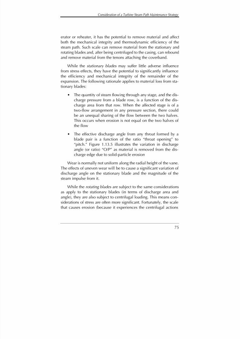
8/20/2019 mantenimiento de turbinas
http://slidepdf.com/reader/full/mantenimiento-de-turbinas 94/575
Consideration of a Turbine Steam Path Maintenance Strategy
75
erator or reheater, it has the potential to remove material and affectboth the mechanical integrity and thermodynamic efficiency of thesteam path. Such scale can remove material from the stationary androtating blades and, after being centrifuged to the casing, can reboundand remove material from the tenons attaching the coverband.
While the stationary blades may suffer little adverse influencefrom stress effects, they have the potential to significantly influencethe efficiency and mechanical integrity of the remainder of theexpansion. The following rationale applies to material loss from sta-tionary blades:
• The quantity of steam flowing through any stage, and the dis-charge pressure from a blade row, is a function of the dis-charge area from that row. When the affected stage is of atwo-flow arrangement in any pressure section, there couldbe an unequal sharing of the flow between the two halves.This occurs when erosion is not equal on the two halves of the flow
• The effective discharge angle from any throat formed by ablade pair is a function of the ratio “throat opening” to“pitch.” Figure 1.13.5 illustrates the variation in dischargeangle (or ratio) “O/P” as material is removed from the dis-charge edge due to solid-particle erosion
Wear is normally not uniform along the radial height of the vane.The effects of uneven wear will be to cause a significant variation of discharge angle on the stationary blade and the magnitude of thesteam impulse from it.
While the rotating blades are subject to the same considerationsas apply to the stationary blades (in terms of discharge area and
angle), they are also subject to centrifugal loading. This means con-siderations of stress are often more significant. Fortunately, the scalethat causes erosion (because it experiences the centrifugal actions

8/20/2019 mantenimiento de turbinas
http://slidepdf.com/reader/full/mantenimiento-de-turbinas 95/575
Turbine Steam Path Maintenance and Repair—Volume One
76
imposed by the rotational effect) will tend to attack the outer regionsof the blade, where centrifugal stresses are lower. However, if theaffected blade elements carry a coverband, the bending stressesimposed on the outer portion of the blade vane can be severe. It ispossible for these stages to suffer damage.
An insidious aspect of solid-particle erosion (SPE) is the erosionof tenons between the vane tip and the underside of the coverband.This erosion can weaken the coverband attachment and possibly
lead to coverband detachment.
SPE is time dependent—effects are dependent upon operatinghours. However, units with a large number of start ups are more sus-ceptible to this type of damage because that is when scale is exfoli-ated from the boiler tubes. A suggested method of monitoring pene-tration ‘d’ is shown in Figure 1.13.6. It shows that monitoring a sim-ple calculation of the effects on stress levels in both the blade vane
and shroud band will provide some indication of when correctiveaction needs to be taken, usually in the form of new blades.
Fig. 1.13.5—The variation in the ratio “O/P” as material is lost from thedischarge edge due to SPE.

8/20/2019 mantenimiento de turbinas
http://slidepdf.com/reader/full/mantenimiento-de-turbinas 96/575
Consideration of a Turbine Steam Path Maintenance Strategy
77
Crack indications in the blade vane. The appearance of a crackin the rotating blade vane or transition from the vane to root platformis sufficient warning that the blades may have reached the end of their useful life. Fracture mechanics methods exist and can beapplied to indicate the rate of crack growth and eventual fracture.However, it is assumed that any crack has sufficient potential for cat-astrophic failure in a steam turbine and the element should not be
returned to service.
One “necessary” exception to this was the case of last stage bladeelements in which cracks appeared at the tie wire hole. They wereevident below the braze material. These cracks were initially found inthree elements. This was a utility unit, whose continued operationwas essential to meet demands for power and heating steam. After theutility ordered replacement blades, it returned the unit to service and
conducted monthly inspections and measurements of the crackedelements. These condition reviews were at weekend outages, whenthe unit could be made available for inspection from within the
Figure 1.13.6 Showing the measurement of “SPE”
penetration at the vane inlet edge.
d1
d2
d3
d4
Depth of erosion
penetration 'd'
Fig. 1.13.6—Showing the measurement of “SPE” penetration at the vane inlet edge.

8/20/2019 mantenimiento de turbinas
http://slidepdf.com/reader/full/mantenimiento-de-turbinas 97/575
Turbine Steam Path Maintenance and Repair—Volume One
78
exhaust hood. After some months, a weld repair of the cracks wasmade on-site and in place. The blades continued to operate withoutproblems. A year after the weld repair, the blades were replaced. Atthat time the cracks had not reappeared, but the utility elected toreplace the blade row with new elements. The history of these bladesfrom initial discovery of the crack is shown in Figure 1.13.7.
On many units, a crack appears at the fillet radius between thevane and root platform. In general, this type of crack cannot beaccepted. However, there have been instances in which such crackshave been removed by grinding and/or polishing and the unitreturned to service. The extent to which this is possible is a functionof the depth of the crack. Such a practice is not recommended as apermanent “fix.” Instead, the blades should be removed andreplaced, as the risk level is high.
Figure 1.13.7
Measured crack growth in a last stage blade. The crack initiating at the tie wire hole. See figure 1.9.17.
BA
L
Extent ofBraze
0.2
0.3
0.4
0.5
4 8 12 16
M e a s u r e
d
l e n g t h o f c r a c k .
Weeks of operation.
Possible crack propogationcurves "A" and "B".
L
Tie wirehole
In situ weld repairat week 16
Initial finding of crack,and return to service
Fig. 1.13.7—Measured crack growth in a last stage blade. The
crack initiating at the tie wire hole. See figure 1.8.17.
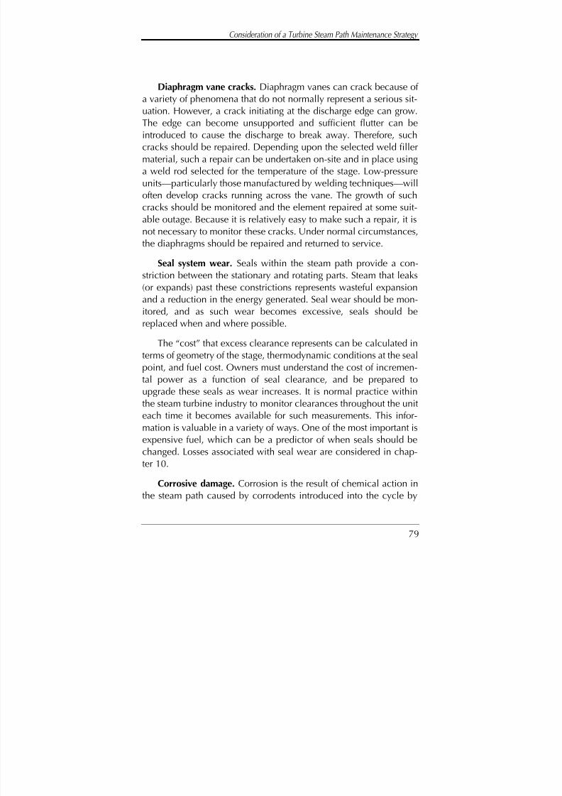
8/20/2019 mantenimiento de turbinas
http://slidepdf.com/reader/full/mantenimiento-de-turbinas 98/575
Consideration of a Turbine Steam Path Maintenance Strategy
79
Diaphragm vane cracks. Diaphragm vanes can crack because of a variety of phenomena that do not normally represent a serious sit-uation. However, a crack initiating at the discharge edge can grow.The edge can become unsupported and sufficient flutter can beintroduced to cause the discharge to break away. Therefore, suchcracks should be repaired. Depending upon the selected weld fillermaterial, such a repair can be undertaken on-site and in place usinga weld rod selected for the temperature of the stage. Low-pressure
units—particularly those manufactured by welding techniques—willoften develop cracks running across the vane. The growth of suchcracks should be monitored and the element repaired at some suit-able outage. Because it is relatively easy to make such a repair, it isnot necessary to monitor these cracks. Under normal circumstances,the diaphragms should be repaired and returned to service.
Seal system wear. Seals within the steam path provide a con-
striction between the stationary and rotating parts. Steam that leaks(or expands) past these constrictions represents wasteful expansionand a reduction in the energy generated. Seal wear should be mon-itored, and as such wear becomes excessive, seals should bereplaced when and where possible.
The “cost” that excess clearance represents can be calculated interms of geometry of the stage, thermodynamic conditions at the seal
point, and fuel cost. Owners must understand the cost of incremen-tal power as a function of seal clearance, and be prepared toupgrade these seals as wear increases. It is normal practice withinthe steam turbine industry to monitor clearances throughout the uniteach time it becomes available for such measurements. This infor-mation is valuable in a variety of ways. One of the most important isexpensive fuel, which can be a predictor of when seals should bechanged. Losses associated with seal wear are considered in chap-
ter 10.
Corrosive damage. Corrosion is the result of chemical action inthe steam path caused by corrodents introduced into the cycle by

8/20/2019 mantenimiento de turbinas
http://slidepdf.com/reader/full/mantenimiento-de-turbinas 99/575
Turbine Steam Path Maintenance and Repair—Volume One
80
external sources. Such corrosion can occur on visible surfaces dur-ing normal inspection outages. Surface-type damage is not normallysignificant in terms of the reliability of the unit. The more seriousaspect of corrosion occurs at points within the steam path where“hideouts” occur, such as at the shrink fit between the wheels andshaft, and the tie wires and tenons that attach the coverband. Unitsshould be inspected (as far as practical) for this type of damage—when damage is discovered, components should be replaced.
Unfortunately, much of this type of damage is usually invisible andcan neither be seen nor adequately monitored.
Surface corrosion is less severe in terms of unit performance, butcan indicate hidden corrosion. Therefore, when surface damage isfound, it is a good practice to use photographs to monitor its extentto compare deterioration and consider future damage at hideouts.Unfortunately, the corrodents causing surface damage may not be
the same as those that concentrate in hideouts and lead to compo-nent cracking.
Checking for crack initiation in hideout regions is complex andoften expensive. Therefore, when such damage is suspected, an eval-uation should be undertaken. If visual inspection confirms the possi-bility, an ultrasonic examination can be undertaken. The shrink fitsbetween wheels, and central spindles are particularly difficult to
access and inspect—it can represent one of the more complex eval-uations expected of the operator engineer.
Fretting damage. Relative movement between components caus-es fretting corrosion as pressure develops between their contactingsurfaces. By definition these surfaces are rarely visible and the dam-age is hard to detect. However, when such damage is found, itsextent should be monitored. It has the potential to loosen fits, which
if design does not allow, can cause a change in the mechanicaldimensions of the component and aggravate what can be an alreadyserious situation.

8/20/2019 mantenimiento de turbinas
http://slidepdf.com/reader/full/mantenimiento-de-turbinas 100/575
Consideration of a Turbine Steam Path Maintenance Strategy
81
There are situations in which relative movement between sur-faces is required. This means that conditions can occur in which theoxide products of fretting can cause a “designed” sliding surface tobecome “solid” and defeat the design requirement.
When this type of damage occurs, it is best recorded by meansof both photographs and casts of the surface, if accessible, fromwhich depth and affected area can be determined in extreme cases.
Water washing erosion. High-pressure water (or water at highvelocity) has the potential to cause significant damage within thesteam path. It can also compromise the integrity of the main struc-tural components of the unit.
Washing or wire drawing type damage on a seal surface canreduce the stage efficiency. Also, the leakage flow can interfere withthe free flow of the expanding steam, possibly causing circulation
losses to be introduced into the flow path. When this type of dam-age is discovered, it is normal to assess the ability of the componentto continue to form effective seals, and if necessary, make repairs.
When washing damage is not sufficient to require immediaterepair action, a monitoring program (as a function of time) should beintroduced. This is a type of damage best recorded by photographs.
The steam path requires exact dimensions of the passage throughwhich the steam is expanding. Washing damage that modifies theshape of the flow passage must be monitored, then repaired orreplacements parts used as soon as the steam path integrity is com-promised.
The other type of material loss mechanism that requires somemonitoring (particularly in older units) is the combined
“washing/impact” material loss (Fig. 1.13.8). Here, material isremoved from a structural component to the extent wall thickness isreduced and the vessel possibly weakened. Damage of this type isnot common, but when it does occur, the results can be severe.
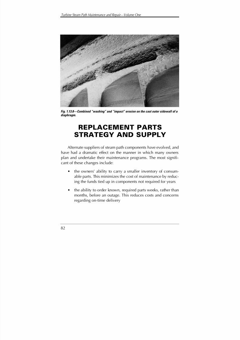
8/20/2019 mantenimiento de turbinas
http://slidepdf.com/reader/full/mantenimiento-de-turbinas 101/575
Turbine Steam Path Maintenance and Repair—Volume One
82
REPLACEMENT PARTSSTRATEGY AND SUPPLY
Alternate suppliers of steam path components have evolved, andhave had a dramatic effect on the manner in which many owners
plan and undertake their maintenance programs. The most signifi-cant of these changes include:
• the owners’ ability to carry a smaller inventory of consum-able parts. This minimizes the cost of maintenance by reduc-ing the funds tied up in components not required for years
• the ability to order known, required parts weeks, rather thanmonths, before an outage. This reduces costs and concernsregarding on-time delivery
Fig. 1.13.8—Combined “washing” and “impact” erosion on the cast outer sidewall of a diaphragm.

8/20/2019 mantenimiento de turbinas
http://slidepdf.com/reader/full/mantenimiento-de-turbinas 102/575
Consideration of a Turbine Steam Path Maintenance Strategy
83
• the owners’ ability to make replace-or-repair decisions forunanticipated damage and deterioration when the unit isopened and its condition determined at the outage
Despite these advantages, the owner will not be able to order allrequired material for each outage and every contingency after theunit is opened. However, many of the emergency parts previouslyunavailable from inventory—parts not generally carried as stock—can be made available from alternate suppliers when inspectionsestablish their need.

8/20/2019 mantenimiento de turbinas
http://slidepdf.com/reader/full/mantenimiento-de-turbinas 103/575
Turbine Steam Path Maintenance and Repair—Volume One
84
REFERENCES1. Dewey, R.P., and N.F. Rieger. Survey of Steam Turbine Blade
Failures , Research Project TIE, Final Report, March 1985
2. Open letter from General Electric: Extending Re-inspectionIntervals-GE Turbine Rotors , Made available at the EPRISteam Turbine-Generator Workshop, Milwaukee, Wisconsin,
August 1995
3. Sanders, W.P. The Review, Assessment, Refurbishment and Efficiency Upgrading of Steam Turbine Units , CanadianElectrical Association, Halifax, Nova Scotia, 1985
4. ABB Power Generation Ltd, Baden Switzerland: Overhaul Plans for Large Steam Turbines-HTGD 690 218 E and HTGD
90 700E5. Recommendations for the Inspection of Steam Turbines: -
VGB - R115 Me. VGB Essen, Germany
6. Sanders, W.P. Potential for Manufacturing Problems to Cause Steam Turbine Blade System Failure, TurbomachineryInternational, Vol. 27, No 7, September 1986
7. Sanders, W.P., and W.R. Southall. A Guide to Mechanical Condition Assessment in the Turbine Steam Path, EPRI Steamand Combustion Turbine Blading Conference, Orlando,Florida, January 1992
8. Timo, D.P. Design Philosophy and Thermal Stress Considerations of Large Fossil Steam Turbines
9. Rieger, N.F. Blade and Rotor Reliability Improvement ,STI/ERPI Seminar, Rochester, New York, June 1991
10. Greco, S. Private correspondence

8/20/2019 mantenimiento de turbinas
http://slidepdf.com/reader/full/mantenimiento-de-turbinas 104/575
85
Steam Path ComponentAlignment and StageSpatial Requirements
INTRODUCTION
In order to achieve an acceptable level of performance from thesteam turbine, two things are essential:
• individual components comprising the steam path are manu-factured in accordance with the design specified requirements
• components are arranged or assembled within the unit sotheir spatial relationship, relative to the other componentswith which they will interact, are correct
This compliance with design requirements will optimize theenergy conversion process and help ensure the structural reliabilityof the system is at an optimum level. The spatial requirement withinthe steam path will be considered in this chapter, along with factors
Chapter
2
8/20/2019 mantenimiento de turbinas
http://slidepdf.com/reader/full/mantenimiento-de-turbinas 105/575
Turbine Steam Path Maintenance and Repair—Volume One
86
influencing the relative positions of the various components one tothe other.
Note: For the purpose of this work the steam path is consideredto comprise the stationary and rotating blade rows, their means of attachment, the rotors, and the casings. To complete the arrangementof the components and help ensure a satisfactory design, it is neces-sary to consider the arrangement made to minimize internal leakageand the leakage occurring from within the casing to other portions of the steam power cycle. In the case of low-pressure sections, leakagesinto the system must also be considered.
Before considering details and requirements of the individualcomponents comprising the steam path, we must review their posi-tional needs relative to each other, and those factors influencingthem when the unit is in operation. Unfortunately, the steam path isavailable for measurement, adjustment, and gauging only in its coldstationary position—conditions under which components must beerected and aligned. When the upper half casing is assembled to thelower and steam is admitted to the unit, the component parts changerelative to one other. These changes are due to various factors influ-enced by steam temperature and pressure and by the mass and rota-tional effects of the rotor system.
During initial manufacture (or repair or replacement of variouspath components) certain spatial relationships in the axial, tangen-tial, and radial directions must be met. Other relationships, by pref-erence, should be met to assist in optimizing performance. The tur-bine supplier will manufacture and assemble the component parts of the steam path to ensure design requirements are achieved withinspecified tolerance bands. The builder monitors this process. In addi-tion, within the organizations of some purchasers, groups have a
responsibility for monitoring these operations.It is not unreasonable to assume a unit, as originally supplied
and erected within the operator’s plant, will conform to design

8/20/2019 mantenimiento de turbinas
http://slidepdf.com/reader/full/mantenimiento-de-turbinas 106/575
Steam Path Component Alignment and Stage Spatial Requirements
87
requirements. Discrepancies with design specification must berecorded and information supplied to the owner, so corrective actioncan be taken as the opportunity arises.
A unit removed from service for inspection and maintenanceoften requires some level of remedial work. Remediation aims toreturn the components and their overall arrangement to conditionsas close to original as possible, consistent with preserving the unit’sperformance potential. It is therefore valuable for plant maintenancestaff to have sufficient knowledge of the component parts and theirassembled requirements to determine the most appropriate course of action in any situation where adjustment or corrective action isrequired.
In terms of manufacturing requirements, the turbine designermust provide exact definitions. These must be made available to themanufacturing portion of the supplier organization to ensure designrequirements are first understood, and then met within specified tol-erances. This information must be provided in such a form that itallows design needs to be understood and followed by the manu-facturing department without ambiguity. Design requirements willalso identify boundaries or engineering tolerances within which thedesign requirements must be met. Tolerances specified by thedesigner should reflect the limits within which components can be
manufactured and still achieve a level of performance consistentwith design predicted values. These tolerances must also reflectachievable values for the processes and component being consid-ered.
The operating engineers and technicians within the purchaser’splant normally do not have access to detailed design information—this is normally considered proprietary. They should, however, have
sufficient opportunity during the manufacturing and erection phaseto ensure that components meet design approval. They will normal-ly have sufficient information on clearances, unit alignment, and the

8/20/2019 mantenimiento de turbinas
http://slidepdf.com/reader/full/mantenimiento-de-turbinas 107/575
Turbine Steam Path Maintenance and Repair—Volume One
88
initial design conditions, and can reestablish conditions to ensurecorrect spacing between the parts is maintained (at least in axial andradial directions).
Engineering tolerances are selected to ensure that the designexpectations of performance levels are met, and where appropriate,components can be disassembled for repair or replacement.Tolerances should also help ensure components can be interchangedwithin similar units in and between stations. Unfortunately, there aretimes when the requirements of design are not sufficiently explicit,or the unit operator has been provided insufficient information. Insuch cases, maintenance staff is unable to evaluate all possiblecourses of action and achieve the most appropriate corrective solu-tions. When mechanical deterioration is found at maintenance out-ages, it is necessary to evaluate the situation and then select correc-tive actions that will restore the unit to a condition enabling it to be
returned to service and operate in a manner acceptable to the owner.This condition may not represent a final repair condition, but will besufficient to make the unit “safe” to the extent it is able to generatepower at an acceptable level of output and efficiency.
The utility engineer cannot be responsible for ensuring the ade-quacy of the design definition provided within the manufacturer’splant. However, the purchaser has an implied responsibility to
ensure this definition exists and that it is applied without compro-mise during manufacture. Such definition should provide sufficientdetail that critical components and specific areas of risk to individ-ual elements are addressed within the utility’s experience. It is alsorealistic to expect that sufficient information is made available to theowner allowing minor repairs and adjustments to be made on-site.The operating engineer should be able to question design detail.
When individual unit components have been manufactured andassembled, they can be erected to form the complete machine. Forsmaller units, such assembly may take place in the manufacturer’splant and the components shipped pre-assembled, or the unit bro-

8/20/2019 mantenimiento de turbinas
http://slidepdf.com/reader/full/mantenimiento-de-turbinas 108/575
Steam Path Component Alignment and Stage Spatial Requirements
89
ken down to major components for shipment. With larger multi-sec-tion designs, shop assembly is normally impractical (except in thecase of prototype units) and complete assembly would add consid-erably to the total costs of the unit.
The process of site erection should result in a unit that is alignedto maximize the unit’s ability to generate power at an acceptablelevel of efficiency—immediately—and to continue to operate reli-ably over the designed plant life. Irrespective of the adequacy andquality of design, if a unit is not installed correctly, it will introduceoperational problems reducing the overall utility of the unit to theowner.
It is also necessary to interface the turbine generator with othermajor pieces of equipment comprising the thermal cycle. Theseimportant interfaces must be made so that they do not prejudice theoperation of either the turbine generator or other equipment.
Control of various areas—and relationships within them—is amajor characteristic in establishing the quality of the turbine steampath. These areas are associated with the expansion and flow direc-tion of working fluid throughout the steam path. Some of this areacontrol is achieved from a correct alignment of the steam path com-ponents as they can affect area relationships to a degree. Also, whilealignment may not control the effective area in all cases, it can havea considerable influence on the efficiency of energy conversion byensuring the steam is directed from blade row to blade row and“shock” and “incidence” losses are minimized.
Areas and area control requirements are considered in somedetail later in this chapter. It is necessary to consider those phenom-ena that influence alignment and the “cold setting condition” of thecomponents—phenomena that are predictable and determined by
the design function for each unit. There are also phenomena thataffect alignment, are unpredictable, and occur normally as a conse-quence of operating conditions. These have the potential to modify

8/20/2019 mantenimiento de turbinas
http://slidepdf.com/reader/full/mantenimiento-de-turbinas 109/575
Turbine Steam Path Maintenance and Repair—Volume One
90
both material properties and physical characteristics of the individ-ual components of the steam path, and ultimately affect alignment.
Stage terminology
A number of terms and phrases describe and define steam pathcomponents. Problems in discussing blades are compounded bymanufacturers using terms not consistent one from another. In this
chapter (and this book), the terms used are defined in Figure 2.1.1,and include the following:
• Rotating blade —the total component, comprising the vane,the root, and all other component attachments machined aspart of the total.
• Blade vane —the airfoil portion, extending from the root block
to the tip. For rotating blades, this tip is the largest diameterof the airfoil; for stationary elements, it is the smallest.
• Profile —the form (or cross section) of the airfoil. This formmay be constant along the vane radial height (cylindrical) orcan vary from section to section (vortex) to accommodate thechanging steam parameters.
• Root or fastening —that portion below the vane and the load
transfer point from the vane to the rotor.
• Root platform —that portion of the root block between the vaneand the root ligaments that carries the load-bearing surfaces.
• Tenons —an integral part of the blade located at the tip diam-eter. They are used to attach an inner or outer coverband.
• Tie wire hole —those stages that have a continuous tie wirerequire an access hole in the vane. This is considered a por-tion or characteristic of the blade.

8/20/2019 mantenimiento de turbinas
http://slidepdf.com/reader/full/mantenimiento-de-turbinas 110/575
Steam Path Component Alignment and Stage Spatial Requirements
91
• Stationary blades —the stationary blade elements mounteddirectly into the casing or blade carrier.
• Diaphragm —comprises three major elements that locate astationary blade row in the casing (inner or outer) and arenormally a welded or cast assembly.
• Outer ring —locates the stationary blade elements in the cas-ing, providing axial position and a steam seal from the high
to low-pressure side of the diaphragm.
• Stationary vanes —perform a similar function to the rotatingvanes and have the same stringent requirements for the profile.
• Inner web —the material forming the expansion passageinner surface and a steam barrier minimizing steam leakagefrom the high- to the low-pressure side of the stationary
blade vane.
Figure 2.1.1Definitions of the blade components.
Tenons
Vane
Profile
Vane
RootPlatform
Blade Root
RootLigaments
R o o t B l o c k
Tie WireHole
χ
Fig. 2.1.1—Definitions of the blade components.

8/20/2019 mantenimiento de turbinas
http://slidepdf.com/reader/full/mantenimiento-de-turbinas 111/575
Turbine Steam Path Maintenance and Repair—Volume One
92
The turbine unit, as installed, should present to the operator/ owner the optimum setting of the components, so when the unitgoes into service it will provide a maximum return on the moneyinvested in making the purchase and justify the selection amongcompeting bids. While many design-selected options of componentsand arrangements within the steam path are a compromise betweencompeting requirements, produced within design specified toler-ances, the final condition should be one allowing the unit to operate
and achieve acceptable levels of performance. Over time, this con-dition will modify, efficiency will deteriorate, and the possibility of mechanical damage and deterioration will arise, possibly affectingunit availability.
Such deterioration means owners should establish a clear mainte-nance strategy (explained in chapter 1). This allows them first to iden-tify, and then correct, any nonconforming conditions as expeditiously
as possible. To do this the maintenance staff should be aware of:
• the signs and indications of deterioration, and how to makeobjective judgments of when corrective action is required
• the potential or total deterioration that can occur if correctiveaction is not taken
• sufficient knowledge of the repair/refurbishment options
available, their possible cost, and the consequences of nottaking such action
Steam turbine performance depends upon some very demandingthermodynamic relationships that are developed and maintainedwithin the expanding steam. Because relatively small changes incomponent geometry or alignment significantly impact the total per-formance of the unit, it is necessary that the critical characteristics of
these requirements are achieved and maintained within the individ-ual elements. What is often not so clear to the operating engineer is

8/20/2019 mantenimiento de turbinas
http://slidepdf.com/reader/full/mantenimiento-de-turbinas 112/575
Steam Path Component Alignment and Stage Spatial Requirements
93
what is “critical,” and what can be ignored to a degree and accept-ed before it becomes critical and requires corrective action.
Spatial requirements exist for steam path components in the radi-al, axial, and tangential directions. Requirements of radial and axialclearances should be observed to help ensure that the performanceof the unit is maintained at an acceptable level. This chapter dis-cusses these and provides some guidance of these different require-ments and the possible consequences of their not being achieved.
PREDICTABLE FACTORS
AFFECTING DESIGN CLEARANCE
Four basic phenomena (or characteristics of operation) are pre-dictable, and influence the radial and axial clearances throughoutthe steam path. These phenomena will affect the total alignmentwithin the stages, and at any location where stationary and rotatingsurfaces are close. The extent to which these phenomena influencethe steam path design can be established (or predicted) by calcula-tion and taken into consideration during the design phase whenselecting and arranging “cold stationary clearances” and bearing ele-vations for the unit at initial assembly and subsequent alignment.
While the designer can calculate the “hot” running relationshipsbetween the stationary and rotating parts, he or she can only mean-ingfully define to the manufacturing and installation departments thespatial relationships, clearances, and setting requirements as theycan be measured and set in the cold stationary condition. Therefore,it is necessary first to consider the types of modifying effects thatneed be evaluated, and then the degree to which they will influencethe cold stationary arrangement of the unit. There are four pre-dictable (and always present) phenomena, whose evaluation

8/20/2019 mantenimiento de turbinas
http://slidepdf.com/reader/full/mantenimiento-de-turbinas 113/575
Turbine Steam Path Maintenance and Repair—Volume One
94
remains part of the mechanical design, and therefore always consid-ered in determining the initial settings.
The influence of these four phenomena must be predicted bydesign, and their total effects compared on some form of clearancechart. These values must then be used to select the optimum cold set-ting at the various locations throughout the steam path with the finalcold settings selected to help ensure “rubs” do not occur, or reducethe possibility of their occurrence during normal predictable opera-tion. These four phenomena or areas requiring considerationinclude:
• the extent and shape to which the rotor will deflect vertical-ly between the bearings due to its own weight, the extent thisis influenced by the temperature of the rotors, and the effectof temperature on material properties
• the differential axial movement that occurs between therotating and stationary portions of the unit due to thermalexpansion of these stationary and rotating parts
• the radial growth of the steam path parts during operationdue to temperature and stress effects
• the axial pressure deflection and thermal creep deformation
(in the higher temperature stages) at the diaphragm innerweb
These conditions must be reviewed, as they occur in the steadystate condition (at all loads and maximum steam conditions), and therate at which they change during transient operation.
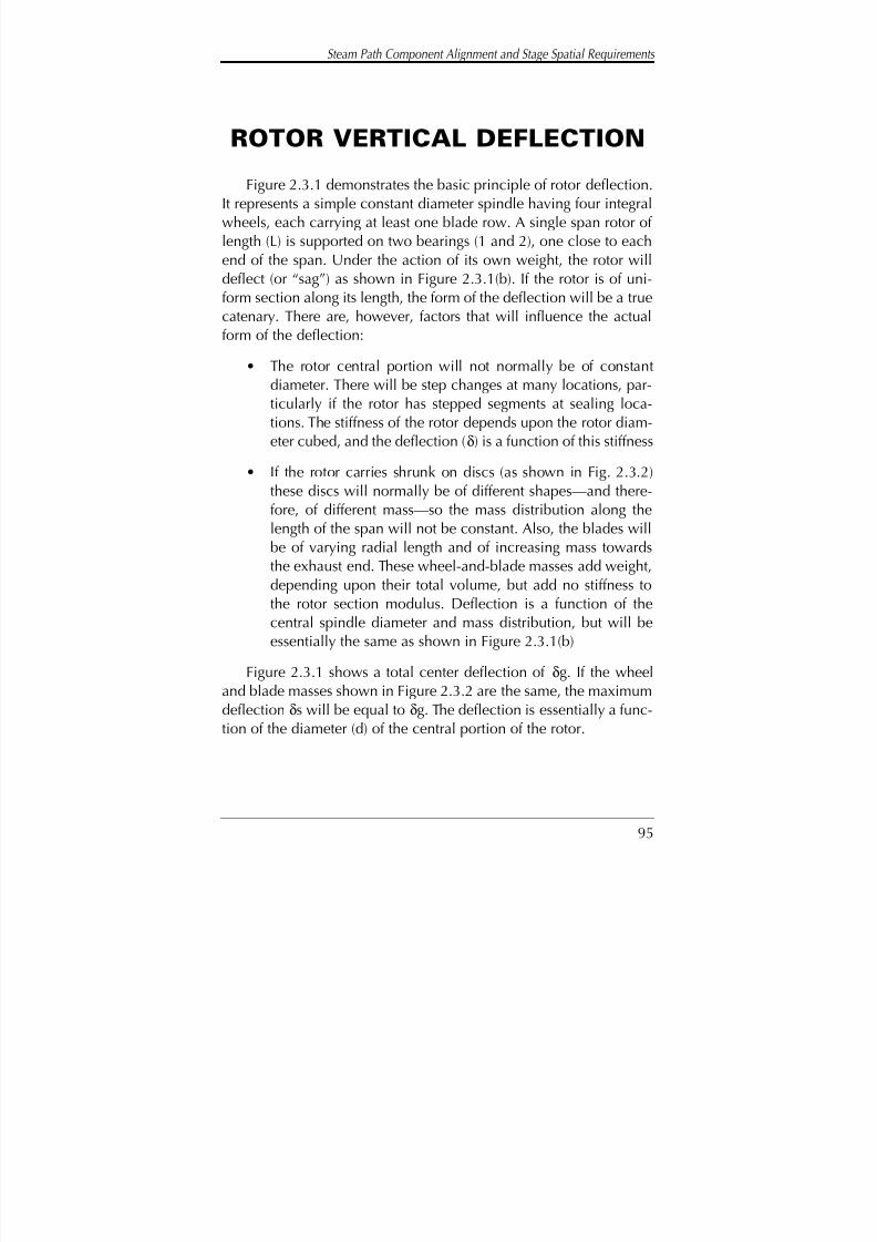
8/20/2019 mantenimiento de turbinas
http://slidepdf.com/reader/full/mantenimiento-de-turbinas 114/575
Steam Path Component Alignment and Stage Spatial Requirements
95
ROTOR VERTICAL DEFLECTIONFigure 2.3.1 demonstrates the basic principle of rotor deflection.
It represents a simple constant diameter spindle having four integralwheels, each carrying at least one blade row. A single span rotor of length (L) is supported on two bearings (1 and 2), one close to eachend of the span. Under the action of its own weight, the rotor willdeflect (or “sag”) as shown in Figure 2.3.1(b). If the rotor is of uni-form section along its length, the form of the deflection will be a truecatenary. There are, however, factors that will influence the actualform of the deflection:
• The rotor central portion will not normally be of constantdiameter. There will be step changes at many locations, par-ticularly if the rotor has stepped segments at sealing loca-tions. The stiffness of the rotor depends upon the rotor diam-eter cubed, and the deflection (δ) is a function of this stiffness
• If the rotor carries shrunk on discs (as shown in Fig. 2.3.2)these discs will normally be of different shapes—and there-fore, of different mass—so the mass distribution along thelength of the span will not be constant. Also, the blades willbe of varying radial length and of increasing mass towardsthe exhaust end. These wheel-and-blade masses add weight,
depending upon their total volume, but add no stiffness tothe rotor section modulus. Deflection is a function of thecentral spindle diameter and mass distribution, but will beessentially the same as shown in Figure 2.3.1(b)
Figure 2.3.1 shows a total center deflection of δg. If the wheeland blade masses shown in Figure 2.3.2 are the same, the maximumdeflection δs will be equal to δg. The deflection is essentially a func-
tion of the diameter (d) of the central portion of the rotor.

8/20/2019 mantenimiento de turbinas
http://slidepdf.com/reader/full/mantenimiento-de-turbinas 115/575
Turbine Steam Path Maintenance and Repair—Volume One
96
• The rotor material temperature will vary along its axial lengthbecause there is a temperature reduction in the stages; there-fore a distribution along the axial length reducing towardsthe exhaust end. The rate of temperature reduction isdependent upon the energy dissipated within the steam path
Figure 2.3.1Deflected form of a simple shaft and
wheel construction.
(a)
(b)
T CD
L
Solid Gashed Rotor
1 2
gδ
Fig. 2.3.1—Deflected form of a simple shaft and wheel construction.
Figure 2.3.2 The deflected form of a shaft with shrunk
on wheels.
(a)
(b)
T CD
L
Rotor with Shrunk on Wheels
1 2
sδ
Fig. 2.3.2—The deflected form of a shaft with shrunk on wheels.

8/20/2019 mantenimiento de turbinas
http://slidepdf.com/reader/full/mantenimiento-de-turbinas 116/575
Steam Path Component Alignment and Stage Spatial Requirements
97
stages. With temperature variation, the mechanical proper-ties of the rotor steel will vary along its axial length, deflect-ing by greater amounts at the higher temperatures
Many rotors are of the barrel form, as shown in Figure 2.3.3(a).In this figure, the basic diameter (D) has been retained at the shaftends, but over the central span, the effective rotor diameter has beenincreased from D (as shown in Figs. 2.3.1 and 2.3.2) to Do.Therefore, the rotor diameter is increased, increasing the stiffnessand increasing its resistance to deflection. The deflection will bereduced. As shown in Figure 2.3.3(b), the total maximum deflectionis δb, which tends to be less than δg.
On each of the rotors shown in Figures 2.3.1, 2.3.2, and 2.3.3there is a coupling flange (c) located at one end, outboard of bear-ing 2 and thrust collar “T.” At this coupling, the turbine rotor is to beconnected to the driven machine (normally a generator). These fea-tures—bearing 2 and thrust collar T of the rotor—provide noincrease in the section modulus, and have only little impact on thedeflected shape. However, the bearing is normally given sphericalseating within its support structure so it is able to line up with the
T C
D
L
Do
Lb
Barrel Rotor
1 2
bδ
Figure 2.3.3 (a) and (b)Deflected from of a barrel construction rotor.
(a)
(b)
Fig. 2.3.3 (a) and (b)—Deflected form of a barrelconstruction rotor.

8/20/2019 mantenimiento de turbinas
http://slidepdf.com/reader/full/mantenimiento-de-turbinas 117/575
Turbine Steam Path Maintenance and Repair—Volume One
98
deflected angle of the rotor at this location. In Figure 2.3.3(c) therotor centerline is inclined to the horizontal at an angle (α). Toaccommodate this inclination, the bearing is turned through thesame angle (α) in the spherical seating of diameter (Dsp). This bear-ing has a white metal thickness “t” and is designed for a radial clear-ance to the journal of “Cl.”
The turbine rotors must be coupled, or connected to the machin-ery they drive. The majority of larger output units comprise morethan one turbine section. When multi-section rotors are coupled,
they can be connected by a flexible element or use a system con-necting individual sections together in such a manner they performas (and have the characteristics of) a single integral shaft—they aresolidly coupled! All modern large rotor designs use the solid cou-pling system. In the following discussions of vertical deflection of multi-segment rotors, a solidly coupled system is assumed, and cou-pling flanges are required on both ends of such shafts. The exceptionis rotors located at the ends of the catenary.
Consider the three-rotor string as shown in Figure 2.3.4. There aretwo turbine rotors—a high-pressure section of length (Lhp) and a dou-
Figure 2.3.3(c) A bearing showing the tilt “ ” in
the spherical seating.
Cl
D
t Cl
Dsp
α
Fig. 2.3.3(c)—A bearing show- ing the “tilt” or “ α” in the spherical seating.
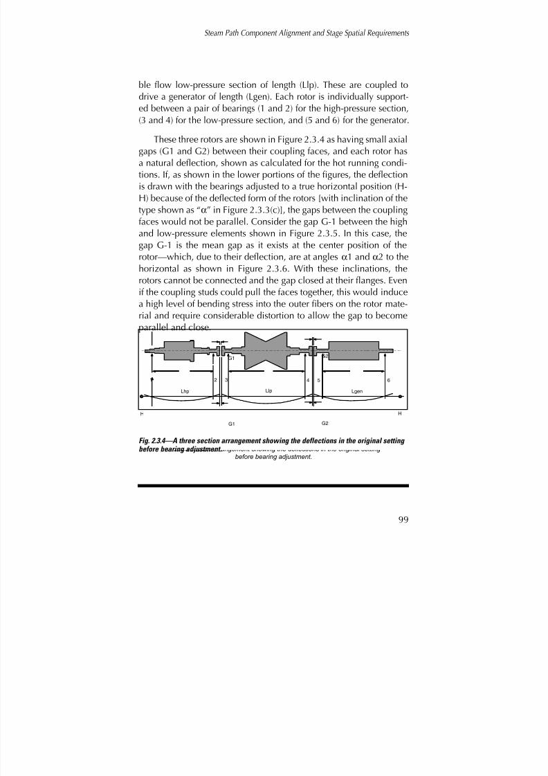
8/20/2019 mantenimiento de turbinas
http://slidepdf.com/reader/full/mantenimiento-de-turbinas 118/575
99
ble flow low-pressure section of length (Llp). These are coupled todrive a generator of length (Lgen). Each rotor is individually support-ed between a pair of bearings (1 and 2) for the high-pressure section,(3 and 4) for the low-pressure section, and (5 and 6) for the generator.
These three rotors are shown in Figure 2.3.4 as having small axialgaps (G1 and G2) between their coupling faces, and each rotor hasa natural deflection, shown as calculated for the hot running condi-tions. If, as shown in the lower portions of the figures, the deflectionis drawn with the bearings adjusted to a true horizontal position (H-H) because of the deflected form of the rotors [with inclination of thetype shown as “α” in Figure 2.3.3(c)], the gaps between the couplingfaces would not be parallel. Consider the gap G-1 between the highand low-pressure elements shown in Figure 2.3.5. In this case, thegap G-1 is the mean gap as it exists at the center position of therotor—which, due to their deflection, are at angles α1 and α2 to the
horizontal as shown in Figure 2.3.6. With these inclinations, therotors cannot be connected and the gap closed at their flanges. Evenif the coupling studs could pull the faces together, this would inducea high level of bending stress into the outer fibers on the rotor mate-rial and require considerable distortion to allow the gap to becomeparallel and close.
Steam Path Component Alignment and Stage Spatial Requirements
H H
Lhp Llp Lgen
1 2 3 4 5 6
G1
G2G1
Figure 2.3.4
A three section arrangement showing the deflections in the original setting before bearing adjustment.
G2
Fig. 2.3.4—A three section arrangement showing the deflections in the original setting
before bearing adjustment.
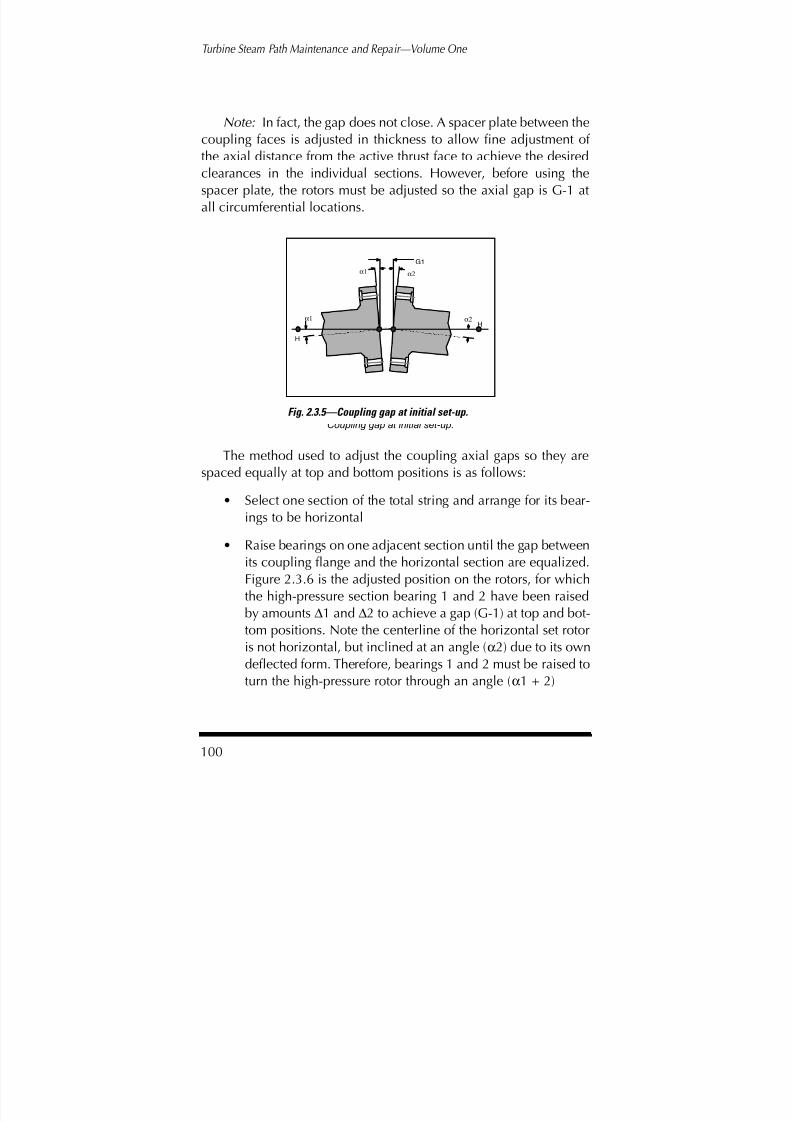
8/20/2019 mantenimiento de turbinas
http://slidepdf.com/reader/full/mantenimiento-de-turbinas 119/575
Turbine Steam Path Maintenance and Repair—Volume One
100
Note: In fact, the gap does not close. A spacer plate between thecoupling faces is adjusted in thickness to allow fine adjustment of the axial distance from the active thrust face to achieve the desiredclearances in the individual sections. However, before using thespacer plate, the rotors must be adjusted so the axial gap is G-1 atall circumferential locations.
The method used to adjust the coupling axial gaps so they arespaced equally at top and bottom positions is as follows:
• Select one section of the total string and arrange for its bear-
ings to be horizontal• Raise bearings on one adjacent section until the gap between
its coupling flange and the horizontal section are equalized.Figure 2.3.6 is the adjusted position on the rotors, for whichthe high-pressure section bearing 1 and 2 have been raisedby amounts ∆1 and ∆2 to achieve a gap (G-1) at top and bot-tom positions. Note the centerline of the horizontal set rotor
is not horizontal, but inclined at an angle (α2) due to its owndeflected form. Therefore, bearings 1 and 2 must be raised toturn the high-pressure rotor through an angle (α1 + 2)
Figure 2.3.5 Coupling gap at initial set-up.
Hα1
α2α1
α2
H
G1
Fig. 2.3.5—Coupling gap at initial set-up.

8/20/2019 mantenimiento de turbinas
http://slidepdf.com/reader/full/mantenimiento-de-turbinas 120/575
Steam Path Component Alignment and Stage Spatial Requirements
101
• Similarly, at the other gap (G-2 between the low-pressuresection and the generator), the generator rotor must beadjusted by raising bearings 5 and 6 by amounts ∆5 and ∆6.
The relative coupling positions are then as shown in Figure2.3.7, where the high-pressure rotor has been adjusted so thecenterline tilt angle has been modified from α1 negative toα2 positive. The coupling face of the high-pressure rotor isnow at the same angle as the low-pressure rotor. Similaradjustments have been made between the low-pressure andgenerator rotors
The rotors of modern turbine generators are solidly coupled andcan be considered as a single shaft of varying sections with loads car-ried at different positions along the axial length. Consider the rotor
Figure 2.3.6 The coupling faces after adjustment to achieve a
constant gap “G1” at top and bottom.
α1+α2
α2
α2
α2
HH
G1
Fig. 2.3.6—The coupling faces after adjustment to achieve a constant gap “G1” at top and bottom.
Figure 2.3.7 The three rotor unit of figure 2.3.4 after bearing vertical height adjustment.
∆2
∆5∆6
Lhp Llp Lgen1
2 34 5
6
G2
H
∆1
H
G1
Fig. 2.3.7—The three rotor unit of figure 2.3.4 after bearing vertical height adjustment.
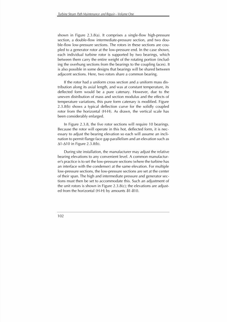
8/20/2019 mantenimiento de turbinas
http://slidepdf.com/reader/full/mantenimiento-de-turbinas 121/575
Turbine Steam Path Maintenance and Repair—Volume One
102
shown in Figure 2.3.8(a). It comprises a single-flow high-pressuresection, a double-flow intermediate-pressure section, and two dou-ble-flow low-pressure sections. The rotors in these sections are cou-pled to a generator rotor at the low-pressure end. In the case shown,each individual turbine rotor is supported by two bearings, whichbetween them carry the entire weight of the rotating portion (includ-ing the overhung sections from the bearings to the coupling faces). Itis also possible in some designs that bearings will be shared between
adjacent sections. Here, two rotors share a common bearing.
If the rotor had a uniform cross section and a uniform mass dis-tribution along its axial length, and was at constant temperature, itsdeflected form would be a pure catenary. However, due to theuneven distribution of mass and section modulus and the effects of temperature variations, this pure form catenary is modified. Figure2.3.8(b) shows a typical deflection curve for the solidly coupled
rotor from the horizontal (H-H). As drawn, the vertical scale hasbeen considerably enlarged.
In Figure 2.3.8, the five rotor sections will require 10 bearings.Because the rotor will operate in this hot, deflected form, it is nec-essary to adjust the bearing elevation so each will assume an incli-nation to permit flange face gap parallelism and an elevation such as∆1-∆10 in Figure 2.3.8(b).
During site installation, the manufacturer may adjust the relativebearing elevations to any convenient level. A common manufactur-er’s practice is to set the low-pressure sections (where the turbine hasan interface with the condenser) at the same elevation. For multiplelow-pressure sections, the low-pressure sections are set at the centerof their span. The high and intermediate pressure and generator sec-tions must then be set to accommodate this. Such an adjustment of
the unit rotors is shown in Figure 2.3.8(c); the elevations are adjust-ed from the horizontal (H-H) by amounts δ1-δ10.
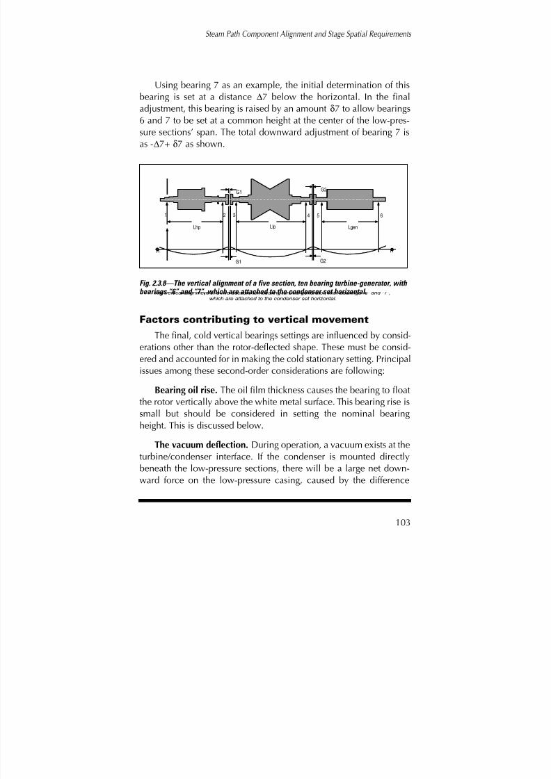
8/20/2019 mantenimiento de turbinas
http://slidepdf.com/reader/full/mantenimiento-de-turbinas 122/575
Steam Path Component Alignment and Stage Spatial Requirements
103
Using bearing 7 as an example, the initial determination of thisbearing is set at a distance ∆7 below the horizontal. In the finaladjustment, this bearing is raised by an amount δ7 to allow bearings6 and 7 to be set at a common height at the center of the low-pres-sure sections’ span. The total downward adjustment of bearing 7 isas -∆7+ δ7 as shown.
Factors contributing to vertical movement
The final, cold vertical bearings settings are influenced by consid-erations other than the rotor-deflected shape. These must be consid-
ered and accounted for in making the cold stationary setting. Principalissues among these second-order considerations are following:
Bearing oil rise. The oil film thickness causes the bearing to floatthe rotor vertically above the white metal surface. This bearing rise issmall but should be considered in setting the nominal bearingheight. This is discussed below.
The vacuum deflection. During operation, a vacuum exists at the
turbine/condenser interface. If the condenser is mounted directlybeneath the low-pressure sections, there will be a large net down-ward force on the low-pressure casing, caused by the difference
H H
Lhp Llp Lgen
1 2 3 4 5 6
G2G1
G2G1
Figure 2.3.8 The vertical alignment of a five section, ten bearing turbine-generator, with bearings “6” and “7”,
which are attached to the condenser set horizontal.
Fig. 2.3.8—The vertical alignment of a five section, ten bearing turbine-generator, withbearings “6” and “7”, which are attached to the condenser set horizontal.

8/20/2019 mantenimiento de turbinas
http://slidepdf.com/reader/full/mantenimiento-de-turbinas 123/575
Turbine Steam Path Maintenance and Repair—Volume One
104
between atmospheric pressure and the vacuum produced in the low-pressure hood. Often the bearings are formed as part of the low-pres-sure hood and carried within it. If the bearing housings are an inte-gral part of the low-pressure structure, then these bearings will besubject to the same vertical forces causing a deflection of the hood,i.e., these bearings will rise and fall with the casing. In establishingthe low-pressure section bearing vertical setting, it is necessary tomake allowance for this movement and consider the effects of part
load and back pressure variations on total elevation.
Some low-pressure section designs have their bearings support-ed from pedestals located between the low-pressure sections. In thiscase, the casing will be subject to elevation changes introduced bythe vacuum force but the rotor will be unaffected. In such designs itmay be necessary to arrange for the unit to have larger radial clear-ances at the shaft-end positions to accommodate the vertical adjust-
ment of the casing relative to the rotor.
Hot well water. During operation, the condenser hot well will fillwith condensate awaiting removal by the condensate and boiler feedpumps. This hot well does, to a degree, act as a reservoir; thereforethe level of water contained in the well will change subject to load,boiler demands, and other factors. It would be expected as waterlevel changes, the static load produced by the weight of water in the
hot well carried by the condenser will change, affecting the heightof the condenser and the load transferred to the low-pressure hoods.
There are various methods of supporting the condenser. Someare suspended from the turbine and given some support from below.Others are carried on spring supports and connected to the turbineby flexible joints. Each will have a different influence on the hooddeflection and needs to be factored into the total vertical setting of
the bearings.Bearing temperature effect. The bearing and its support structure
are subject to temperatures above atmospheric and temperature vari-
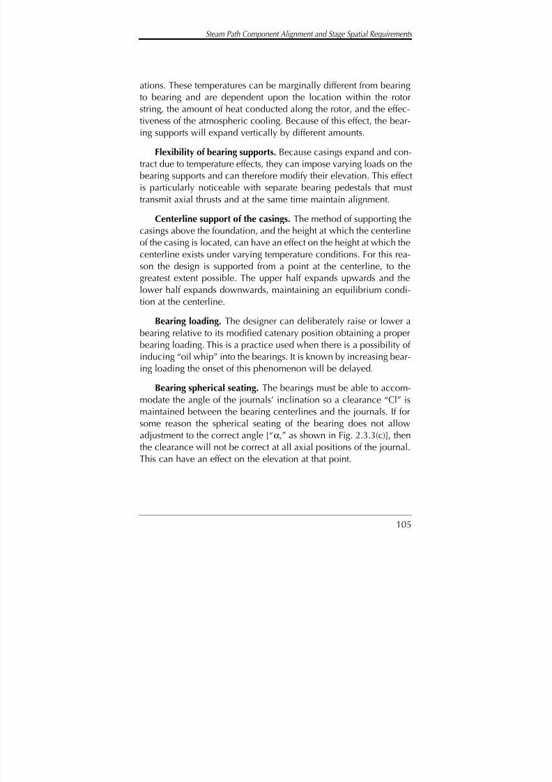
8/20/2019 mantenimiento de turbinas
http://slidepdf.com/reader/full/mantenimiento-de-turbinas 124/575
Steam Path Component Alignment and Stage Spatial Requirements
105
ations. These temperatures can be marginally different from bearingto bearing and are dependent upon the location within the rotorstring, the amount of heat conducted along the rotor, and the effec-tiveness of the atmospheric cooling. Because of this effect, the bear-ing supports will expand vertically by different amounts.
Flexibility of bearing supports. Because casings expand and con-tract due to temperature effects, they can impose varying loads on thebearing supports and can therefore modify their elevation. This effectis particularly noticeable with separate bearing pedestals that musttransmit axial thrusts and at the same time maintain alignment.
Centerline support of the casings. The method of supporting thecasings above the foundation, and the height at which the centerlineof the casing is located, can have an effect on the height at which thecenterline exists under varying temperature conditions. For this rea-son the design is supported from a point at the centerline, to thegreatest extent possible. The upper half expands upwards and thelower half expands downwards, maintaining an equilibrium condi-tion at the centerline.
Bearing loading. The designer can deliberately raise or lower abearing relative to its modified catenary position obtaining a properbearing loading. This is a practice used when there is a possibility of inducing “oil whip” into the bearings. It is known by increasing bear-ing loading the onset of this phenomenon will be delayed.
Bearing spherical seating. The bearings must be able to accom-modate the angle of the journals’ inclination so a clearance “Cl” ismaintained between the bearing centerlines and the journals. If forsome reason the spherical seating of the bearing does not allowadjustment to the correct angle [“α,” as shown in Fig. 2.3.3(c)], thenthe clearance will not be correct at all axial positions of the journal.
This can have an effect on the elevation at that point.
8/20/2019 mantenimiento de turbinas
http://slidepdf.com/reader/full/mantenimiento-de-turbinas 125/575
Turbine Steam Path Maintenance and Repair—Volume One
106
It is clear from these considerations that final bearing elevations“δ1-δ10” are selected with care after an evaluation of the variousfactors that can influence their operating elevation. This elevationmust be achieved with considerable accuracy during site erectionand subsequent adjustment. Some of these factors have minimaleffect on the final design elevation—however, they do have an effect.It is necessary for the designer to consider these, if not in each spe-cific case, at least during the development phase of the design rules
formulated to ensure the final specified elevation will help ensurevertical alignment is maintained at all operating conditions.
Sideways shift
In addition to the requirements of vertical adjustment needed toachieve axial gaps of “G1” and “G2” at top and bottom of the rotors,these elements must be aligned side to side along their axial lengthso the rotor line is true and the coupling gaps “G1” and “G2” (Figs.2.3.4 and 2.3.5) are identical side to side as well as top to bottom. Itmust be recognized, however, that the true operating shape of therotor does not run on this “true” side-to-side line set in the cold sta-tionary condition. There are one or two minor influences that willcause some adjustment but they are of a very low level and can beignored for all practical purposes.
The facts of a bearing oil rise were discussed previously. If thehot running position of a bearing is considered, it will be seen thatfrom the cold stationary position—with the rotor journal centerlocated directly above the vertical centerline of the bearing [Fig.2.3.9(a)]—there will be a positional shift as the unit goes into oper-ation. In operation, an oil wedge is formed between the bearingliner’s metal surface and rotor journal, so the rotor will in effect float
on this oil film. This film is not of uniform thickness and will beestablished as a wedge [Fig. 2.3.9(b)].
8/20/2019 mantenimiento de turbinas
http://slidepdf.com/reader/full/mantenimiento-de-turbinas 126/575
Steam Path Component Alignment and Stage Spatial Requirements
107
In the hot running position, the rotor has a “center shift” from Ato B. This shift can be considered to comprise two components—”δv” in the vertical direction (discussed earlier), and a shift of “δh” inthe horizontal direction. The vertical rise is considered in settingbearing elevation. Normally, this vertical rise is greater than the hor-izontal side shift. This horizontal shift must also be reviewed in termsof adequacy of the unit’s total rotational stability. The “δh” deflectionis a relatively small amount, but where bearings of considerably dif-
ferent diameters are adjacent to each other, this can have an effecton the oil wedge shape of both, and must be considered by designin establishing cold clearances.
Figure 2.3.9The center line shift due to the
oil wedge.
h
vδ
δ
(a)
(b)
ω
B
A
Fig. 2.3.9—The center line shift due to the oil wedge.

8/20/2019 mantenimiento de turbinas
http://slidepdf.com/reader/full/mantenimiento-de-turbinas 127/575
Turbine Steam Path Maintenance and Repair—Volume One
108
DIFFERENTIAL EXPANSIONDuring operation, the stationary and rotating components of the
turbine absorb and reject heat energy from the steam and expandand contract with the temperature changes this heat introduces. Therotating and stationary portions accept and reject this heat, both indifferent amounts and at different rates, depending upon their totalmass and the extent to which they can radiate this heat to othermedia. Because these stationary and rotating components expandand contract by different amounts and at different rates, there will bea relative positional shift between them from the cold stationaryposition during normal operation. This difference becomes evenmore pronounced during transient conditions, when dramatic tem-perature changes and (in emergency conditions) heat generation canoccur within the steam path due to frictional heating caused by rotor
rotation in a partially evacuated or stagnant steam atmosphere.
Because they are anchored to the turbine foundation block at var-ious locations, the casings—normally one for each section—willexpand in an axial direction away from these anchor points. Theextent of this expansion in any one casing is influenced only by theamount of heat absorbed, rejected, and retained by individual cas-ings. The extent of expansion in any one casing is unaffected by other
casings and components of the unit.The rotating portions are solidly coupled and have a total move-
ment from their one anchor point. The anchor point is the thrustbearing and the contact point at the active thrust face. The positionof the thrust bearing is chosen to minimize the differential expansionin the higher condition stages, where the effects of differentialexpansion have, or can be made to have, less effect on the perform-
ance of the unit.Figure 2.4.1 is a simple, single-section, eight-stage turbine. This
unit has a thrust bearing axial location “T,” as indicated. At this posi-

8/20/2019 mantenimiento de turbinas
http://slidepdf.com/reader/full/mantenimiento-de-turbinas 128/575
Steam Path Component Alignment and Stage Spatial Requirements
109
tion there is contact between the rotating (thrust collar) and stationary(thrust bearing plates) components. This position represents the onlypoint within the unit where there will be no relative axial movementbetween the stationary and rotating components as a consequence of temperature changes. In this unit, steam is admitted through a controlstage “C1.” This position within the unit represents the highest tem-perature the metal will experience. The steam will expand within thesteam path through the remaining seven stages—steam will flow to
the right (indicated as +”A”) and will also leak through the sealing sys-tem installed at the shaft end (indicated as -”A”).
Note that expansion to the right of the thrust bearing has beendesignated as positive movement and expansion to the left as nega-tive movement. This is a convention used only to explain the effectsof differential axial movement.
Consider the effects of the steam temperatures on the individualstages of the steam path. The control stage (accepting the inflowing
Figure 2.4.1The differential expansion in a single section containing eight stages.
A b s o l u t e L i n e a r E x p a n s i o n
Axial Length or position
ThrustBlockActiveFace
CasingExpansion
DifferentialExpansion
∆ ax
Steam Flow Direction
CouplingGap
C1 2 3 4 5 6 7 8
RotorExpansion
T
-A +A
Fig. 2.4.1—The differential expansion in a single section containing eight stages.

8/20/2019 mantenimiento de turbinas
http://slidepdf.com/reader/full/mantenimiento-de-turbinas 129/575
Turbine Steam Path Maintenance and Repair—Volume One
110
steam) is the highest temperature region that will expand (by anamount in the positive direction). Figure 2.4.1 shows the slope of thecontrol stage expansion curve will be the steepest of the individualstages. In the stages to the right of the control stages, temperatureswill be lower and therefore the rate of expansion will be less (but stillin a positive direction). The extent to which high temperature steamwill expand through the rotor end seals will influence the tempera-ture in this region. To the left of the thrust bearing, heat will be con-
ducted down the rotor material causing a negative movement of therotor.
Figure 2.4.2 shows the control stage, where steam is admitted tothe steam path. It enters the rotating blade at a temperature “Ti,”expands through the rotating blades to a temperature “To,” and givesa mean blade temperature “Tb,” which is a function of both “Ti” and“To.”
Figure 2.4.2 The temperature variations in a stage with
some level of reaction.
Ta
Ti To
Tr
Tc
Te
Tb
Tre
da1
da2
Fig. 2.4.2—The temperature variations in a stage with some level of reaction.

8/20/2019 mantenimiento de turbinas
http://slidepdf.com/reader/full/mantenimiento-de-turbinas 130/575
Steam Path Component Alignment and Stage Spatial Requirements
111
The rotor wheel temperatures are similar to the blade vane on itsinlet and discharge faces. These temperatures will influence the rotorbody, together with any heating effect of the steam expanding pastthe nozzle box. The temperature will range from “Ti” to “Te.” Thetotal result of this heating is for the rotor to expand away from thethrust bearing by an amount depending upon the mean temperatureand the axial span of the stage.
The casing inner surface will also heat to about the same tem-perature as “Tb.” The casing, however, has an outer surface; it isinsulated but it will lose heat to the atmosphere surrounding it, andwill then be at a somewhat lower temperature (“Ta”). This means thatthe mean temperature in the casing will be lower than the meaneffective temperature of the rotating portions (considering the cool-ing that takes place at the outer wall). The casing temperature (“Tc”)is a function of both “Tb” and other temperatures achieved by the
rotor material.
The nozzle plate will be exposed to temperatures higher than“Ti”—temperatures equal to the inlet temperature of the steam. Anysteam chamber within the casing will also achieve inlet temperature,which will tend to raise the temperatures of the stationary portionsby some small amount in this region. They will still suffer the effectof heat loss from the outer surface. In many designs—where a dou-
ble casing design is used, for instance—the outer wall temperatureof an inner casing (which locates the stationary blade rows) is thetemperature of the steam surrounding that casing.
With these changes in the relative axial position of the stationaryand rotating components, the axial clearances (set in the cold axialposition) are modified by this differential expansion. Two hot runningaxial clearances are of importance in determining the initial settings
of the individual stages in the unit—”da1” and “da2,” shown inFigure 2.4.2. These will be discussed in greater detail later.

8/20/2019 mantenimiento de turbinas
http://slidepdf.com/reader/full/mantenimiento-de-turbinas 131/575
Turbine Steam Path Maintenance and Repair—Volume One
112
Consider again the single casing unit in Figure 2.4.1. This unitcomprises a central spindle with a control and seven impulse stages.At normal operating conditions the rotor and casing will expandfrom their anchor points in the rotor in the positive direction from thethrust bearing active face. The rotor has its highest temperatures atthe front end, and so the growth in axial length will occur at thegreatest rate at this location with the rate of growth decreasing as theexhaust end is approached. In this unit, the casing is also anchored
at the thrust-block location and will also expand in the positivedirection; however, because it is slightly cooler (losing some heatthrough its outer surface), it will not expand to the same extent.
The actual location of the thrust bearing at the front end of theunit is also important. Often this will be contained in a pedestal sup-porting the bearings and possibly the control mechanisms. The cas-ing may or may not be keyed to and supported from this pedestal; it
depends upon the axial location of the anchor, and is a function of the arrangement selected by design.
The curve of total rotor expansion will be of the form shown.Similarly, the casing will expand in the same direction, but to a less-er amount because of its lower mean temperatures. The difference inexpansion occurring between these two curves is termed the differ-ential axial expansion.
There is also some expansion from the thrust bearing active facein the negative direction. The temperature of this portion of the rotor(to the left of the thrust block) is established by heat conducted alongthe shaft from the central portion of the unit. Similarly, the casingwill expand in a negative direction, again at a lower rate than occursin the rotating portions of the unit.
Figure 2.4.3 shows the five-section unit previously shown as
Figure 2.3.8—in this case, the thrust bearing axial location (“T”) hasbeen added. In this design, the thrust bearing is located at the bear-ing pedestal between the high and intermediate pressure (reheat)

8/20/2019 mantenimiento de turbinas
http://slidepdf.com/reader/full/mantenimiento-de-turbinas 132/575
Steam Path Component Alignment and Stage Spatial Requirements
113
sections. Also shown in the lower portion of this figure is the axialmovement from the thrust bearing of the solidly coupled rotor andthe stationary portion from their anchor points to the foundation. Atthe thrust bearing axial position, the rotor has zero axial movementrelative to the stationary elements. The casings for the high and inter-mediate pressure sections are normally located from thepedestal/bearing support. They often have a support platform builtonto them to locate the stationary portions on either side of them.
Using the same nomenclature in this figure as in Figure 2.4.1, itcan be seen that movement (or expansion) to the left (away from thethrust bearing) is termed “negative” (for convenience), while move-ment to the right is termed “positive.” Because of their locations,both the high-pressure rotor and casing expand away from the thrustface to the left of the thrust bearing active face. Both are thereforeconsidered to have a negative movement. Figure 2.4.3 shows thetotal movement of the rotor begins at a thrust face (which is the zeropoint), whereas the casing initial (zero) point is located at some smalldistance to the left—possibly considered the support point, since it
Figure 2.4.3Indicating the differential expansion in a five section turbine-generator, showing the rotors
expanding from the thrust bearing, and the casings from their anchor points.
HP Reheat LP A LP B Generator
AeAc
Ar
Negativemovement Positive
movement
Thrustblock 'T'
Reheatcasing LP-A casing LP-B casing
Coupledrotor
expansion
T o t a l r o t o r
e x p a n s i o n
Differential expansion isequal to the vertical distancefrom the rotor to the casing
expansion lines
Generatorcasing
Z e r o a x
i a l m o v e m e n t l i n e
HP casing
Anchor points
Fig. 2.4.3—Indicating the differential expansion in a five section turbine-generator,showing the rotors expanding from the thrust bearing, and the casings from their
anchor points.

8/20/2019 mantenimiento de turbinas
http://slidepdf.com/reader/full/mantenimiento-de-turbinas 133/575
Turbine Steam Path Maintenance and Repair—Volume One
114
is at the outer surface of the bearing pedestal. In fact, these small dis-tances have little influence on the differential movement, but it iswise to be aware of their existence.
An examination of the high-pressure section expansion charac-teristics makes it clear that modified axial clearances exist betweenthe hot rotating and cold stationary settings during normal operation.If a stage in the high-pressure section is examined (Fig. 2.4.4), theaxial clearances will modify. In this figure, clearances from the sta-tionary to rotating blade at the steam path are shown as “Cao” and“Cai” at the outer and inner radial locations, respectively. As heat isadmitted, both rotating and stationary elements will expand to theleft. Because the stationary portions will have a lower mean temper-ature than the rotor, they will move by a smaller amount, and theclearances “Cao” and “Cai” will increase by the amount of the dif-ferential expansion at the location of transition from the stationary to
rotating rows. The clearance “Ci” (between the stationary portionsand the preceding rotating portions) will decrease by the amount of the differential expansion at that axial location.
Another factor to be considered is the minimum clearancebetween the diaphragm and adjacent wheels along their commonface (“Cxi” and “Cxo”). This clearance normally occurs at the innerdiameter position and will be considered in greater detail later.
If labyrinth seals are located at the inner diameter of thediaphragm and are of the “hi-lo” type, their axial position detail(shown by the dimension “g” and “h” in Fig. 2.4.4) must be moni-tored. Ultimately, there could be rubs of the seal strips on the rotorcastellations that will normally destroy the seal strips. This willdegrade efficiency and stage output. These considerations also applyto the reheat section, except the expansion of the rotor and casing
are in the positive direction.It is clear from a consideration of the low-pressure rotors (Fig.
2.4.3) that the accumulated axial movement of a solidly coupled

8/20/2019 mantenimiento de turbinas
http://slidepdf.com/reader/full/mantenimiento-de-turbinas 134/575
Steam Path Component Alignment and Stage Spatial Requirements
115
rotor system represents considerable movement in the positive direc-tion. The outer casings of these sections connect to external portionsof the foundation at some suitable point. Figure 2.4.3 shows how this
occurs for both the “A” and “B” sections at their casing centerlines(position of steam admission). This is a convenient location, as itimposes the minimum adjustment requirement on any crossover/ around piping that transports steam from the reheat section exhaustto the low-pressure sections inlet. However, there are designs thatanchor the low-pressure outer casing at the point nearest the thrustbearing.
As an example of low-pressure section clearance requirements,consider the first stages of the double flow low-pressure section“LPA” shown diagrammatically in Figure 2.4.5. In the cold stationary
Figure 2.4.4Showing the axial clearances which
should be considered in setting the
cold stationary positions.
g
Cao
Ci
th
s
Cai
Cxi Cxo
Fig. 2.4.4—Showing the axial clearances which should be considered in setting the cold stationary positions.

8/20/2019 mantenimiento de turbinas
http://slidepdf.com/reader/full/mantenimiento-de-turbinas 135/575
Turbine Steam Path Maintenance and Repair—Volume One
116
condition axial clearances “Cat” and “Cag” stand between the sta-tionary and rotating blade rows at the turbine end and generator [Fig.2.4.5(a)].
When the unit reaches steady operating temperatures and hasadjusted to its normal axial operating position [Fig. 2.4.5(b)], positivemovement occurs in the rotating components in both flows. The totalaxial movement at this point is the sum of the movement in thereheat section from the thrust bearing to the “LPA” coupling, plus anymovement from the “reheat/LPA” coupling to the stage point beingconsidered. This can be defined as an amount “+datr” at the turbineend flow, and “dagr” at the generator end flow. At the turbine end,the stationary blade row will have a negative movement by anamount, “-dats” towards the thrust bearing (the casing beinganchored at its centerline). These two operational movements will
Cat
TurbineEnd.
Steam FlowSteam Flow
S e c t i o n C e n t e r L i n e .
Rotating
row
Stationary
rowRotating
row
Stationary
row
SteamInlet
Cag
Rotatingrow
Stationaryrow
Rotatingrow
Stationaryrow
+datr
-dats
+dags
+dagr
GeneratorEnd.
Caot Caog
Caog = Cag - dagr + dagsCaot = Cat - datr - dats
(a)
(b)
Coldstationarycondition
Normal hot
runningcondition
Figure 2.4.5 Showing the change in axial position from the cold stationary
Fig. 2.4.5—Showing the change in axial position from the cold stationary posi- tion to the hot rotating position.

8/20/2019 mantenimiento de turbinas
http://slidepdf.com/reader/full/mantenimiento-de-turbinas 136/575
Steam Path Component Alignment and Stage Spatial Requirements
117
cause a modification of the turbine end clearances. Therefore, thenormal hot running clearance at the turbine end “Caot” is given by:
Caot = Cat – datr – dats
Similarly, at the generator end, there is a positive movement(“dagr”) of the rotating portions of the unit, and another positivemovement of the stationary components (“dags”). This produces ahot running clearance (“Caog”), which is given by:
Caog = Cag + dagr – dags
In the second low-pressure section (“LPB”), there is an evengreater axial movement of the rotor since it includes the total axialexpansion of the “LPA” rotor, but the reasoning in establishing thesecold axial clearances is identical to that discussed for section “LPA.”
In the generator, the cold setting must be adjusted to recognize
this total rotor expansion. The axial clearances in the generator arenot quite as critical—attention must be given to the hydrogen seals—and the effects of differential expansion on performance are mini-mal. There is a magnetic center to the flux field but its axial positionis not critical, and can be accounted for in the cold setting.
The thrust bearing can be mounted at various axial locations. Themost appropriate for any design is dependent upon the steam path
or section configuration. A common location for the thrust bearingin multi-section units is between the high and reheat (or the inter-mediate pressure) sections. This gives both sections the advantage of minimal differential expansion and therefore the ability to maintainclose axial clearances in both sections. This is done to minimizeaxial movement in these higher-pressure stages, regions where leak-age would have the more significant degrading effect on efficiency.The cold stationary axial clearances at any position must be setaccording to the differential axial movement predicted at the loca-tion being considered.

8/20/2019 mantenimiento de turbinas
http://slidepdf.com/reader/full/mantenimiento-de-turbinas 137/575
Turbine Steam Path Maintenance and Repair—Volume One
118
The casings of the high and reheat sections are not connected, soboth must have independent anchor positions. A similar logicapplies to low-pressure casings that are anchored to minimize axialthrusts on crossover pipes, or in the case of nuclear units, on thevalve system at the low-pressure inlet.
Figure 2.4.6 shows an arrangement suitable for a low-steamcondition multi-flow unit—e.g., a geothermal application, wheremulti-flows are required for the larger outputs. In this design, thethrust bearing is located at the front end of the unit, typically in apedestal containing the control mechanisms and the number “1”bearing. The “LPA” casing is anchored to the foundation in theregion of the number “3” bearing, but just outside the casing region.The casings (normally fabrications) are interconnected through a
Figure 2.4.6 The differential expansion of a geothermal unit comprising only low pressure sections. This unit has
a rotor with a thrust bearing at the front pedestal, and the interconnected low pressure casings
are attached to the foundation at a point near the number 3 bearing.
T
(a)
DFLP" DFLP"
V
Rotor
Casing anchor point of casing, just outboard of the number "3" bearing.
"1" "2" "3" "4" "5" "6" "7"
Casing
Thrustbearing
-ve movement
+ve movement
∆
ExciterGenerator
ax
VV
Fig. 2.4.6—The differential expansion of a geothermal unit comprising only low pres- sure sections. This unit has a rotor with a thrust bearing at the front pedestal, and the interconnected low pressure casings are attached to the foundation at a point near the number 3 bearing.

8/20/2019 mantenimiento de turbinas
http://slidepdf.com/reader/full/mantenimiento-de-turbinas 138/575
Steam Path Component Alignment and Stage Spatial Requirements
119
shared bearing pedestal, containing both bearings “2” and “3.” Itcan be seen that there is considerable negative movement of the“LPA” casing, and the same degree of positive movement in the“LPB” casing. Because of the lower temperatures in these units, theactual amount of differential is small, and this design splits the totalmovement so both double-flow sections can employ small axialclearances. The generator and exciter are shown in this figure but,as in the case of the unit shown in Figure 2.4.3, these are not too
sensitive to differential movement and can be set with a reasonabledegree of latitude.
Transient operating conditions
In addition to the requirements of normal operating clearances, itis necessary to consider thermal transients that can occur in the work-ing fluid during operation. Under transient conditions, stationary androtating portions of the unit are subject to steam temperature changesand accept and reject heat energy. This change in heat energy levelsoccurs at different rates between the various components and influ-ences the relative positions they attain.
Considerations of transient conditions—and resulting expan-sions—are of considerable importance during the design phase andthe setting of “cold stationary clearances.” They affect the minimum
and maximum differential clearance required to ensure that rubsbetween the stationary and rotating components do not occur dur-ing both normal operation, start up, and shutdown, when both “shortor cold” and “long or hot” rotor conditions occur. The “long rotor”condition occurs when the rotor temperature is above those of thestationary portions of the unit by an amount greater than the normaloperating temperature differential. “Short rotor” conditions exist
when the rotor temperature is below that of the stationary portionsby more than those achieved in normal operation.

8/20/2019 mantenimiento de turbinas
http://slidepdf.com/reader/full/mantenimiento-de-turbinas 139/575
Turbine Steam Path Maintenance and Repair—Volume One
120
“Short” and “long” rotor conditions occur during transients thatare most often created by start up, shutdown, or when steam is beingadmitted to or cut off from the steam path. However, these condi-tions can also be introduced by boiler temperature excursion, whenthere are load changes, or in an emergency, when load is rejectedfrom the generator and the main stop valves close.
These various transient phenomena introduce an imbalance ordifference in steam path temperatures from “normal.” Then, becauseof the difference in thermal inertia between the rotating and station-ary portions of the unit, they will accept and reject heat at differentrates, expanding axially by different amounts to the extent the run-ning clearances must be modified from normal operating values.
In the following analysis the following symbols and suffixes areused:
C axial clearanced axial distance adjustment
a normal design operating position
o off design operating position
t turbine end of unit
g generator end of unit
n normal temperature condition
h hot temperature condition
c cold temperature condition
r the turbine rotating portion
s the turbine stationary portion
Long (hot) rotor. Occasionally, the steam path rotor temperatureexceeds the temperature of the stationary portions by an amount inexcess of the normal operating temperature differential. In such cases,there will be a period of time during which the differential expansion
of the rotor relative to the stationary portions of the unit is larger thannormal. Under these circumstances steam path portions of the unitmust be examined to ensure there is no reduction of hot running

8/20/2019 mantenimiento de turbinas
http://slidepdf.com/reader/full/mantenimiento-de-turbinas 140/575
Steam Path Component Alignment and Stage Spatial Requirements
121
clearances to the extent interference will occur. Interference wouldcause rubs between stationary and rotating portions of the unit.
Figure 2.4.7(a) shows a three-section turbine with high, reheat,and double-flow, low-pressure sections (the generator has not beenincluded). Under normal operations, the differential expansion posi-tions are shown, with the total differential expansion at the end of the high- and low-pressure sections indicated as “∆axhpn” and“∆axlpn” [Fig. 2.4.7(b)]. During periods of transient conditions—when the rotor achieves a temperature in excess of the stationaryportions by a larger differential temperature—there will be changesin the relative positions between the components.
In the high and reheat sections, this results in an increase in theaxial clearance between the stationary and rotating components“Cao” and “Cai” (Fig. 2.4.4) and a decrease in the clearance “Ci”between the rotating blade discharge and the inlet to the followingstationary row. Normally, the clearances represented by “Ci” are sig-nificantly larger than the “Ca” clearances, so this is rarely of con-cern. However, in high temperature, high-pressure stages, it isalways prudent to ensure “rubs” will not occur, particularly at theinner diameter of the diaphragm (clearances “Cxi” on the inlet and“Cxo” on the outlet sides of Figure 2.4.4), where there could also beboth elastic and plastic deformation of the web.
The differential expansion changes give total differentials of “∆axhph” at the high-pressure end and “∆axlpn” at the generatorend of the double flow low-pressure section [Fig. 2.4.7(c)].
There are other considerations in the double-flow low-pressuresection. While axial clearances between stationary and rotating rowswill increase in one flow, in the other they will also change as a con-sequence of the thermal difference—but the direction of the result-
ing movement will be reversed. It should also be noted that the nor-mal differential expansion in the low-pressure sections are large

8/20/2019 mantenimiento de turbinas
http://slidepdf.com/reader/full/mantenimiento-de-turbinas 141/575
Turbine Steam Path Maintenance and Repair—Volume One
122
because of the accumulated effect of rotor expansion and the intro-duction of such transients can aggravate the overall situation.
Figure 2.4.7(d) shows a diagrammatic representation of twostages—the first stages in the two flows of the double flow low-pres-sure section. We assume the unit is running at steady conditionsrather than being subjected to start-up transients—i.e., it shows thenormal running clearance of “Caot” at the turbine end and “Caog”at the generator end flows, as defined by the equations on page 117.The values shown and defined in Figure 2.4.5 are the “normal hotrunning clearance.”
Under conditions of the hot rotor transients, the turbine end willexperience expansion. Because of the hot rotor condition, there willbe an additional rotor growth (“dhrt”). Similarly, the stationary por-tions will expand in the negative direction (from a centerline posi-tion) by an amount “-dhst.” These movements will give a final hottransient running clearance from “Caot” to “Coth” of:
Coth = Caot – dhrt – dhst
This analysis shows that during the long (hot) rotor condition, theexpansion at the low-pressure section turbine end causes a decreasein the axial clearance of (dhrt + dhst), i.e., the rows move, closingthe axial clearance.
Similarly, at the generator end of the low-pressure section, theturbine rotor will have an additional positive movement (“dhrg”),and the stationary portions will have expanded by an additionalamount (in the positive direction) of “dahg.” This means the normalhot running clearance (“Coag”) will have changed. This expansiongives a hot transient running clearance “Cogh” of:
Cogh = Coag + dhrg – dhsg
This analysis shows that during the long (hot) rotor condition, theexpansion at the generator end of both stationary and rotating por-

8/20/2019 mantenimiento de turbinas
http://slidepdf.com/reader/full/mantenimiento-de-turbinas 142/575
Steam Path Component Alignment and Stage Spatial Requirements
123
Figure 2.4.7 The “long” or “hot” rotor. In (b) is shown the normal differential expansion, in (c)
the effect of temperature reduction, and in (d) the modified operating
position on the first stages in the low pressure section.
0
0
HP Reheat DFLP
∆axlpn
∆ axhpn∆
∆
axlph
axhph
Rotornormal
Casingnormal
Rotorhot
Casinghot
+ve movement
Caog
(TE) (GE)
Coth Cogh
dhrt
Long Rotor Axial Adjustment
T h r u s t B e a r i n g
Hot steam flow Hot steam flow
(a)
(b)
(c)
(d)
Rotatingrow
Stationaryrow
Rotatingrow
Stationaryrow
-dhst
Caot
dhrgdhsg
S e c t i o n C e n t e r L i n e
Expansion-ve +ve
Normal
Hot
Steam Inletand LP anchor
point
"n" indicates normal rotor conditions"h" indicates hot rotor conditions
-ve movement
Fig. 2.4.7—The “long” or “hot” rotor. In (b) is shown the normal differ- ential expansion, in (c) the effect of temperature reduction, and in (d)the modified operating position on the first stages in the low pressure section.

8/20/2019 mantenimiento de turbinas
http://slidepdf.com/reader/full/mantenimiento-de-turbinas 143/575
Turbine Steam Path Maintenance and Repair—Volume One
124
tions is in the positive direction. However, the rotor will expand bya larger amount, with the final effect being the clearance willincrease by an amount (dhrg - dhsg).
The total “expansion effect” at the two extreme positions of theunit can be noted as follows:
• high-pressure end, total negative movement changes fromnormal (“∆axhon”) to hot (“∆axhph”)
• low-pressure extreme, from normal (“∆axlpn”) to the hotcondition (“∆axlph”)
Note: In the analysis discussed above—and for the cold rotorcondition below—the unit arrangement is as shown in Figure 2.4.7,with the thrust block and low-pressure section anchors as shown.There can be a number of locations for both arrangements, and each
unit should be analyzed for the particular arrangement used.A similar analysis can be made for transients that occur when the
rotor is cooled by the admission of steam, which cools it faster thanthe containing stationary portion.
Short (cold) rotor. When the steam temperature reduces sud-denly—such as load rejection with valve closure—or when the unitis shut down, two situations may result:
• Unit speed does not reach emergency values (<110% nor- mal) and the main stop valves do not close. In this situation,steam continues to be admitted to the unit using the controlvalves to lower overspeed in a controlled manner. The unit isthen reconnected to the grid as soon as it can be synchro-nized. Under these circumstances, there will be some reduc-tion in internal temperatures gradients and a quenching of
the materials of the steam path; however, with the readmis-sion of steam, it is unlikely there will be significant metaltemperature changes or that mean metal temperatures will

8/20/2019 mantenimiento de turbinas
http://slidepdf.com/reader/full/mantenimiento-de-turbinas 144/575
Steam Path Component Alignment and Stage Spatial Requirements
125
drop to the extent there will be significant change in the axialexpansion and location of the steam path parts
• An emergency overspeed condition is reached, i.e. , the over- speed transient reaches emergency values (>110% normal) or the rotor accelerates at a rate allowing emergency conditions to be reached. Under these circumstances, the main controlvalves will close and the rotor speed will be reduced. Littlesteam is admitted to the unit before the valves close and unitspeed will reduce until it can be placed on turning gear.During such an overspeed transient, a number of phenomenahave the potential to affect the temperature of the fluidremaining in the unit. These include sections containingdeposited moisture—this moisture will flash to steam as thepressure decays. There can also be frictional windage heatingof the steam remaining in the sections, causing temperatures
to increase to values much higher than normally experienced
Under circumstances of sudden cooling, the rotors—of smallerthermal mass and immersed in the cooler steam—will lose heatfaster than the casings; rotor temperatures will tend to be lower thanthose of the casing. When this occurs, differential expansion curveswill be modified—from those shown in Figure 2.4.8(a), with a hot-end differential expansion of “∆axhpn” and a low-pressure end dif-
ferential expansion of “∆axlpn”—to those shown in Figure 2.4.8(c),with a hot-end total differential expansion of “∆axhpc,” and a low-pressure end differential expansion of “∆axlpc.”
Note: In low-pressure sections, design geometries can be select-ed so rotors will be of larger thermal mass, and cool slower than thecasing, which can be a simple fabrication subjected to ambient tem-peratures. This must be considered in establishing the possible rotor
conditions—particularly for units with multi-flow exhausts.The “short rotor” condition will modify the clearance between
the stationary and rotating blade rows shown in Figure 2.4.8(d).

8/20/2019 mantenimiento de turbinas
http://slidepdf.com/reader/full/mantenimiento-de-turbinas 145/575
Turbine Steam Path Maintenance and Repair—Volume One
126
Figure 2.4.8 The “short” or “cold” rotor. In (b) is shown the normal differential expansion, in (c) the effect of
temperature reduction, and in (d) the modified operating position
on the first stages in the low pressure section.
HP Reheat DFLP
(a)
0
∆
∆axhpc
0
axhpn C
∆axlpn
∆axlpc
Rotornormal
Casingnormal
Casingcold
-ve movement +ve movement.
R
Rotorcold
Caot
(TE) (GE)
Cotc Cogc
dcrtdcrg
Cold steam flowCold steam flow
Short Rotor Axial Adjustment
Casingcold
Rotorcold
(d)
(b)
(c)
Caog
dcst dcsg
S e c
t i o n
C e n
t e r L
i n e
Expansion-ve +ve
Normal
Cold
T
h r u s
t B e a r i n g
Steam Inletand LP anchor
point
"n" indicates normal rotor conditions"c" indicates cold rotor conditions
Rotatingrow
Stationaryrow
Rotatingrow
Stationaryrow
Fig. 2.4.8—The “short” or “cold” rotor. In (b) is shown the normal differentialexpansion, in (c) the effect of temperature reduction, and in (d) the modifiedoperating position on the first stages in the low pressure section.

8/20/2019 mantenimiento de turbinas
http://slidepdf.com/reader/full/mantenimiento-de-turbinas 146/575
Steam Path Component Alignment and Stage Spatial Requirements
127
These normally run clearances “Caot” at the turbine end and “Caog”at the generator end and will be modified as shown to “Cotc” and“Cogc” at the turbine and generator ends respectively. Dependingupon the rate at which the rotor cools relative to the casing, it is pos-sible for the rotor to be at a lower temperature than the casing.
At the turbine end—and under conditions of a cooled rotor—there will be a rotor contraction towards the thrust bearing of “dcrt;”similarly, the stationary portions will contract, but move in a positivedirection, towards the section center (anchor) by an amount “dhst.”These movements will give a final cold transient running clearance(“Cotc”) as follows:
Cotc = Caot + dcrt + dcst
This analysis shows during the short (cold) rotor condition, thecontraction at the turbine end causes an increase in the axial clear-
ance at the turbine end of (dcrt + dcst), i.e., the rows move, increas-ing the axial clearance.
Similarly, at the generator end, the turbine rotor will experiencea negative movement or contraction of “dcrg” towards the thrustbearing, and the stationary portions will have contracted by anamount “dcsg” in the negative direction towards the section center-line. Therefore, the normal hot running clearance (“Caog”) will have
changed. This contraction gives a cold transient running clearance(“Cogc”) of:
Cogc + Caog – dcrg + dcsg
This analysis shows during the short (cold) rotor condition, thecontraction at the generator end of both stationary and rotating por-tions is in the negative direction. However, the rotor will contract bya larger amount, with the final effect being the clearance willincrease by an amount (dhrg - dhsg).

8/20/2019 mantenimiento de turbinas
http://slidepdf.com/reader/full/mantenimiento-de-turbinas 147/575
Turbine Steam Path Maintenance and Repair—Volume One
128
The design process considers and evaluates these “long” and“short” rotor conditions based on assumptions of the possible maxi-mum and minimum temperature excursions that can be anticipated.This excursion review establishes minimum “cold stationary clear-ances” so there will be as few “rubs” as possible during operation.In addition to considering the clearance effect within the steam pathstages, it is necessary to consider other locations within the unitwhere clearances are tight and rubs or excessive movement could
affect total unit operation. Such locations can include oil seals adja-cent to bearings, particularly at the low-pressure section where oilcould be drawn into the condenser; also, at barring gear locationswhere misalignment of the gears can occur. Each of these axial posi-tions needs evaluation and the cold clearance set, recognizing thedamage potential these locations represent under the influence of transients.
The effects of thrust reversal
The steam path utilizes a high-energy fluid at various pressurelevels that exert a thrust on each surface with which they are in con-tact. Around the surfaces of the rotating portions of the unit thesepressures exert axial thrusts that must be balanced. On the inner sur-faces of the casing these pressure thrusts are contained by the hoop
stresses developed in the casings. Pressure “drops” also exist acrossthe stationary blade rows, and the pressures developed between theblade attachments and the casings balance these thrusts. This fluidpressure is sufficient that in the case of diaphragms they are limitedfrom moving in an axial direction by the force developed betweenthem and the casing location. However, as will be discussed below,the diaphragms, as a consequence of this axial thrust, will deflectelastically; in certain circumstances, in a plastic manner as well. In
the axial direction there are thrusts that need to be balanced.
In addition to the axial force developed by the steam pressure,there is also an axial thrust developed as a consequence of steam

8/20/2019 mantenimiento de turbinas
http://slidepdf.com/reader/full/mantenimiento-de-turbinas 148/575
Steam Path Component Alignment and Stage Spatial Requirements
129
momentum change within the rotating blade rows. This thrust acts inthe same direction as the pressure declines from inlet to exhaust.
As a consequence of steam momentum and fluid pressure with-in the casing, an axial thrust develops on each rotor, causing it toattempt to move in the direction of these axial forces to the greatestextent possible. To prevent (or limit) such unrestricted movement, theunit contains an axial thrust bearing. Such a bearing must containfaces intended to control and limit this axial migration while main-taining axial rotor position within close tolerances. Thrusts are in factdeveloped on the rotor in both directions, and the thrust bearing issized to control these total differential effects and minimize damagethat might result from excessive level or reversal of thrust.
If the unit is to operate as designed, the design engineer isresponsible to evaluate thrust levels developed, and then to selectdesign parameters to help ensure the net or resultant thrust is alwaysin the same direction, and of manageable magnitudes. In addition, amargin is always designed into selecting this thrust bearing sufficientto allow for some level of operating damage and for deficiencies tobe accommodated as they affect the thrust. Four phenomena, orcomponents, affect the total axial thrust.
Piston thrust. At any position on the rotor where there is achange of section (increase or decrease in diameter), there will be anaxial thrust produced. These forces are known as piston thrusts, andin magnitude are equal to the product of the pressure acting on thevertical face and the exposed axial annulus area. Such thrusts arepresent at both ends of each rotor and at other section changes. Theend thrusts oppose each other. By judicious design they can bearranged to help balance thrust to a considerable degree.
Consider the four-wheel rotor shown in Figure 2.4.9(a). Here the
radial dimensions are shown as diameters “D1” to “D4.” [For con-venience it is assumed that the rotor body diameter (“D4”) is con-stant at all axial positions]. In the details of the rotor end positions

8/20/2019 mantenimiento de turbinas
http://slidepdf.com/reader/full/mantenimiento-de-turbinas 149/575
Turbine Steam Path Maintenance and Repair—Volume One
130
[Fig. 2.4.9(b) and (c)], where flow-restricting glands (“G”) are used,there are changes in shaft diameters in addition to axial positionpressure changes. Consider the high-pressure end. Two gland ringshave a pressure differential across the first ring (“G1”) of “P1” to“Pg1” and on the second ring (“G2”) from “Pg1” to “Pa.” At the shaftposition, where the steam enters the first gland ring, there is anexposed axial area of:
This annular area has a steam pressure (“P1”) acting on it.Therefore, there is an axial thrust (“Ta”) developed that is equal to:
Similarly, at the first “leak off” position between glands “G1” and
“G2” there is a vertical exposed area of:
Dr
D4 D5 D6 D7
G3G4
Pg3
Pa
(c)
-ve
D1 D2 D3 D4
G2G1 P1
Pa
Pg1
(b)
+ve
D1 D2 D3 D4 D5 D6 D7
G1 G2 G3 G4
P1 P2 P3 P4 P5
1 23
4
(a)+ve -ve
Steam Flow
-ve
P5
(a)
Fig. 2.4.9—The “Piston Thrusts” developed on the rotor ends.
π4 (D4
2
- D3
2
)
Ta = P1 .π4
(D42 - D3
2)
π4
(D32 - D2
2)

8/20/2019 mantenimiento de turbinas
http://slidepdf.com/reader/full/mantenimiento-de-turbinas 150/575
Steam Path Component Alignment and Stage Spatial Requirements
131
With a face pressure of “Pg1,” this produces an axial thrust (“Tb”)of:
Similarly, at the second “leak off” position—steam escaping pastgland ring “G2”—there is an axial thrust “Tc” of magnitude:
In this case, “Pa” is shown as atmospheric pressure being equalto 14.7 psia. At the shaft end, another small thrust (“Td”) is producedby atmospheric pressure. Its magnitude is:
Because the final “leak off” is to the atmosphere, thrusts “Tc” and“Td” can be combined. However, for purposes of demonstratingmethodology, these are best considered separately.
The total axial thrust developed at the high-pressure end(“Thp+”) can be found from:
The implication of the “+” sign is to indicate the same conven-tion of considerations or phenomena acting to the right are given apositive notation, and those to the left a negative notation.
At the low-pressure end the same reasoning is applied. This givesan axial thrust “Te,” in the negative direction at entry to the leak off “G3” of:
Tb = Pg1 .π4
(D32 - D2
2)
Tc = Pa .π
4
(D2
2 - D1
2
)
Td = Pa .π4
. D12
Thp+ = Ta + Tb + Tc + Td
Te = P5 .π4
(D42 - D5
2)

8/20/2019 mantenimiento de turbinas
http://slidepdf.com/reader/full/mantenimiento-de-turbinas 151/575
Turbine Steam Path Maintenance and Repair—Volume One
132
At the leak off between “G3” and “G4,” there is a thrust (“Tf”)that again is negative, and has the value:
Using the same logic, the thrust (“Tg”) at the atmospheric “leakoff” is:
The axial thrust developed on the shaft end must be consideredin terms of the thrust developed on the coupling flange; the fact thatair exists on the coupling face (both sides), and the coupling flanges(when joined) are of the same diameter. It is also necessary to con-sider that the total thrust (“Thp-”) is negative. Therefore “Thp-” isgiven by:
This axial thrust (“-Thp”) represents the total thrust acting to theleft in Figure 2.4.9(a) and (c). Taken together with any thrust devel-oped on the coupling flange face—normally zero—the total axialpiston thrust (“Taxp”) developed on this rotor can therefore be foundfrom:
The gland systems shown in Figure 2.4.9 represent a relatively
simple arrangement. In fact, the gland systems at both high- and low-pressure ends of the rotor are considerably more complex than thoseshown in Figure 2.4.9. Figure 2.4.10 is a sealing system in which one
Tf = Pg3 .π4
(D52 - D6
2)
Tg = Pa .π4
(D62 - D7
2)
Thp- = Te + Tf + Tg
Taxp = (Thp+) + (Thp-)

8/20/2019 mantenimiento de turbinas
http://slidepdf.com/reader/full/mantenimiento-de-turbinas 152/575
Steam Path Component Alignment and Stage Spatial Requirements
133
“leak off” (between gland rings “G2” and “Gx”) goes to a sub-atmos-pheric gland-sealing condenser. In this case, the total thrust (“Thp+”)would be determined from:
This arrangement is significant because the pressure “Px” is sub-atmospheric, and has therefore a lesser effect on the total axialthrust.
Other considerations of total piston thrust are those related toreverse flow steam paths, where either the high-pressure expansion
is broken into two separate and opposite flows, or where a combinedhigh and reheat steam path are contained on a combined rotor.Consider the following arrangement: In the high/reheat section of a
Thp = Pa .π4
(D42 - D3
2) + Pg1 .π4
(D32 - D2
2)
+ Px .π4
(D22 - Dx
2) + Pa .π4
(Dx2)
=
π4 Pa(D4
2
- D3
2
) + Pg1(D3
2
- D2
2
) Px(D2
2
- Dx
2
) + Pa .(Dx
2
)
Figure 2.4.10 A shaft end sealing system with a sub-atmospheric leak off at “Px”.
Gx
G2
G1
Pg
PxP1
Dx D2 D3 D4+ve
Fig. 2.4.10–A shaft end sealing system with a sub-atmospheric leak off at “Px”.

8/20/2019 mantenimiento de turbinas
http://slidepdf.com/reader/full/mantenimiento-de-turbinas 153/575
Turbine Steam Path Maintenance and Repair—Volume One
134
portion of a combined rotor shown in Figure 2.4.11, the high-pres-sure section has a shaft diameter of “D4a” and the reheat section, ashaft diameter of “D4b.” At the crossover position—with a seal sec-tion “Gc”––the rotor has a diameter of “D8.” Therefore, there is anegative thrust (“Th”) of:
A similar positive thrust (“Tr”) develops on the reheat section.This is given by:
Th = Pa .π4
(D4a2 - D8
2)
Tr = Pa .π4
(D4b2 - D8
2)
Figure 2.4.11
Showing the piston effects at a reversal point in a high/reheat section.
D4a D4bD8
Gc
P1
P8
1
8
2
9
+ve -ve
Pressure Balanceholes.
Dra
Drb
Steam Flow
Steam Flow
Fig. 2.4.11—Showing the piston effects at a reversal point in a high/reheat section.

8/20/2019 mantenimiento de turbinas
http://slidepdf.com/reader/full/mantenimiento-de-turbinas 154/575
Steam Path Component Alignment and Stage Spatial Requirements
135
The resultant thrust (“T”) at this crossover position is equal to thedifference in the two values given by the previous equation and thatfollowing.
This piston thrust is a major contributor to the total thrust theaxial bearing must accommodate. By selection of rotor diametersand arrangement of the steam path elements, this thrust can bereduced to a value the bearing can carry without exceeding accept-able values.
Wheel face thrust. If a pressure differential exists across a rotat-ing blade row, there must also be a pressure difference (and there-fore axial thrust developed) on any wheel face or vertical face that ispart of that row.
Many stages are designed with the blade elements carried on theouter rim of wheels that are either formed integral with the centralrotor or shrunk onto it. With this structure, thrust develops acrossthese wheels, which act in the axial direction of steam flow and ineffect represents another form of the piston thrust. Consider the four-stage rotor shown in Figure 2.4.9. Its four wheels each have a bladeroot diameter of “Dr.” Total thrust developed on the wheels is thesum of the individual wheel thrusts—which is again the product of
the pressure differential across the wheels—and their vertical facearea. For the rotor shown in Figure 2.4.9, the axial wheel thrust(“Tw”) is given by:
In the “impulse” design stage, the magnitude of the reaction atthe vane root section is relatively small—and normally just posi-
tive—although negative reaction stages have been designed to meetother requirements. This means the pressure differential across eachstage is relatively small. However, many impulse wheels have a large
Tw =π4
[Dr2
- D42
] . (P1 - P2) + (P2 - P3) + (P3 - P4) + (P4 - P5)
T = Tr - Th

8/20/2019 mantenimiento de turbinas
http://slidepdf.com/reader/full/mantenimiento-de-turbinas 155/575
Turbine Steam Path Maintenance and Repair—Volume One
136
axial area, and can therefore develop significant levels of thrust inthe steam flow direction. To minimize the possibility of this thrustcausing excessive axial loads, “pressure balance holes” in thesewheels allow equalization of pressure, helping to minimize the axialthrust developed across them. These holes also allow for the effectsof transients or mechanical damage that could introduce some mal-distribution of stage pressures. This allows them to equalize them-selves without allowing high levels of thrust to develop.
Consider the wheel shown in Figure 2.4.12. A pressure balancehole of diameter “d” has a mean diameter “Dh.” At this mean diam-eter there is no pressure differential across the wheel, as pressure isequalized by flow through it. However, at the diameter of the bladeroot “Dr,” some small pressure differential exists due to the root reac-tion. If this root section pressure drop is defined as “dP,” then a lin-ear reduction from “dP” at “Dr” to zero at “Dh” can be assumed toexist. Then the wheel thrust “Twh” in this case can be taken to be:
Figure 2.4.12 The pressure balance hole
“ ”
Ds
Dr
Dh
d
D4
P2 P3T
+ve
Fig. 2.4.12—The pressure balance hole at a diameter “Dh”.
Figure 2.4.13 A single reaction stage on a
drum rotor.
Dri Dro
+ve
DtoDti
D4
P2P3
Do
Tr = 0.5 . dP.π4
(Dr2 - Dh
2)
Fig. 2.4.13—A single reaction stage on a drum rotor.

8/20/2019 mantenimiento de turbinas
http://slidepdf.com/reader/full/mantenimiento-de-turbinas 156/575
Steam Path Component Alignment and Stage Spatial Requirements
137
Another portion of this thrust that can be determined is normal-ly of such small magnitude it is ignored for all practical purposes.This is the thrust “Tcv” developed on the coverband, and is equal to:
Where “P2” and “P3” are the pressures existing at the tip section,they are not of the same magnitude as those present at the root sec-tion; a vortex calculation must be performed to determine their val-ues. The mean diameter of the coverband is “Ds” and its radial thick-ness “T.”
In the case of a reaction stage carried on a drum rotor (e.g., therotating blade row shown in Fig. 2.4.13), a pressure drop developsacross the rotating blade and acts on the root section—from diame-ters “Dri” to “D4,” and at the tip or outer diameter, from “Do” to“Dti.” If it is assumed that these pressures vary with radial reaction,then the thrust “Twr” can be found from:
Note: This equation is developed from considerations of pres-sure differentials from inlet to discharge rather than total thrusts inthe upstream and downstream direction. This equation also ignoresthe effect of sloped sidewalls and the axial component of any thrustdeveloped on them. (See also the equations on page 138.) It alsotakes into account:
• the effect of blade damage —if the blade rows sustain anyform of mechanical damage, it modifies the row dischargearea and affects the pressure distribution throughout the
steam path (and therefore, the axial thrust). In the majority of incidents, this will be of no consequence; however, therecould be circumstances in which this can increase the load
Tcv = (P2 - P3) . π4
. T . Ds
Twr =π4
{ (Dri2 - D4
2) . (P2r - P3r) + (Do2 - Dti
2) . (P2t - P3t) }

8/20/2019 mantenimiento de turbinas
http://slidepdf.com/reader/full/mantenimiento-de-turbinas 157/575
Turbine Steam Path Maintenance and Repair—Volume One
138
on the thrust bearing to unacceptable levels, and correctiveaction must be taken
• the effect of chemical deposits —deposits will often form as aconsequence of impurities carried over with the steam. Theseimpurities will often be deposited on the blade vanes andwill tend to close the throat. Under normal circumstances,these deposits will build to a thickness of 0.005" to 0.010"i.e., they will close the throat by 0.010" to 0.020." However,circumstances can arise in which much thicker deposits willform. This will influence the pressure distribution and there-fore, the axial thrust
Blade annulus thrust. A pressure differential exists across therotating blade annulus. This totally axial force is the product of therotating blade row pressure drop and the annulus area across whichit acts. From the inlet to the row, the pressure is not of equal magni-tude along the entire radial height, because of the radial flow com-ponent of the steam velocity. However, at the discharge surface, thepressure is sensibly constant at all radial heights. For blades of rela-tively small radial height (height/mean diameter <0.20")—as shownin Figure 2.4.13—the pressure at the mean diameter (P2 and P3) canbe used with sufficient accuracy that the axial thrust “Tba” on therow can be determined from:
Equation 2.4.13(a) is suitable for use with an impulse blade row(Fig. 2.4.12) with a relatively small pressure drop developed acrossit. However, in the case of a reaction stage having a high degree of reaction, it is necessary to evaluate the entire stage, including those
developed on the inner and outer sidewalls of the vane itself. Figure2.4.13 shows a reaction rotation blade row that has “sloped” side-walls. In this case the total “Tba” thrust consists of the followingterms:
Tba = (P2 - P3) . π4
(Ds-T/2)2 - Dr
2

8/20/2019 mantenimiento de turbinas
http://slidepdf.com/reader/full/mantenimiento-de-turbinas 158/575
Steam Path Component Alignment and Stage Spatial Requirements
139
The outer and inner sidewalls carry a mean pressure 0.5(P2 + P3).
The total thrust (“Tba”) is therefore the sum of these three com-ponents:
Note: The equation contains those terms of the previous for the
wheel thrust “Twr,” but has assumed a constant pressure along theradial height of this rotating blade row at both inlet to and dischargefrom the row. This introduces no great error for small radial heightelements. The first equation has also ignored the sloped sidewallsand any axial component of thrust developed on them. Examine allequations in this section for blade annulus thrust.
For larger radial height blades, it is necessary to determine the
pressure distribution along the inlet height of the vane. From this canbe determined the total thrust, either by considering the mean thrust,or determining the thrust over small radial sections, and adding theirindividual values to determine the row total.
Steam momentum thrust. The change in momentum as steamflows between the blade vanes is shown in Figure 2.4.14—the forcediagram on a blade due to the change of steam momentum. The total
thrust component “AD” produces a component in the axial directionequal to “DE.” This value must be determined for each stage in theunit and added to the thrusts developed by the other mechanisms
Tba1 = P2 π4{(Do2 - Dti2) +(Dti2 - Dri2) +(Dri2 -D42)}
Tba3 = -P2 + P3
2.π
4
(Dto
2 - Dti
2
) +
P2 + P3
2.π
4
(Dro
2 - Dri
2
)
Tba = Tba1 + Tba2 + Tba3
Tba2 = - P3π4{(Do
2 - Dto
2) +(Dto2 - Dro
2) +(Dro2 - D4
2)}

8/20/2019 mantenimiento de turbinas
http://slidepdf.com/reader/full/mantenimiento-de-turbinas 159/575
Turbine Steam Path Maintenance and Repair—Volume One
140
present in the unit. This axial force is directed downstream in thedirection of steam flow.
For any blade row, the thrust due to the change in steam momen-tum can be determined from consideration of the vector diagram andthe change in the axial component of velocity that is achieved. For
the vector diagram shown in Figure 2.4.15, the change in axial com-ponent of velocity “∆Cax” is given by—
—so for the axial thrust “Tdv” for a stage flow of “m” #/sec, thetotal thrust can be determined as:
Pressure balance pistons
Reaction stages have an axial thrust component that is consider-ably larger than equally-sized impulse blades. This means single-flow sections normally require “pressure balance pistons” in order toreduce thrusts to a level that normal-sized thrust bearings can
accommodate the loads developed in normal service.
Figure 2.4.14The force diagram and its components on a turbine blade.
Vector ED is the axial thrust component.
Fw = m. EA
Ft = m. DA
Fax = m. DE
Fw
FtFaxA
D
E
Fig. 2.4.14—The force diagram and its components on a turbine blade.Vector ED is the axial thrust component.
∆Cax = {C1.Sinα1 - W2.Sinβ2}
Tdv = mg {C1.Sinα1 - W2.Sinβ2}

8/20/2019 mantenimiento de turbinas
http://slidepdf.com/reader/full/mantenimiento-de-turbinas 160/575
Steam Path Component Alignment and Stage Spatial Requirements
141
The balance piston consists of a wheel machined onto the rotor.It is designed to operate with a pressure drop across it sufficient tobalance the portion of the axial thrust (which is in excess of whatmight normally be developed) and capable of being carried by an
acceptably-sized thrust bearing. Figure 2.4.16 shows a typical high-pressure, single-flow reaction section. The expansion consists of animpulse control stage with a pressure drop across the rotating bladesfrom “P1” to “P2,” and then a series of rotating blades with a pres-sure reduction from “P2” to “P3.” Piston thrusts also develop on eachend of the rotor. As a consequence of the reaction blade pressuredrops, a large thrust develops towards the exhaust end. To counterthis, a balance piston is incorporated into the design, with a glandseal system above it (“G4”) to limit leakage. The thrust developed onthis piston (“Tp”) acts in the opposite direction to the blade reactionthrust, and is equal to:
Using the pressure balance piston makes certain variables avail-
able to the designer to help select a suitable geometry. Theseinclude:
Tp =π4
.{P1. [D82 - D7
2] - P5. [D8
2 - D9
2] }
Figure 2.4.15 The vector diagram of a single stage, showing the variation
of velocity in the flow of steam through a stage.
C1C2
U
W1
W2
β1α1 β2
δ
Cax∆
Fig. 2.4.15—The vector diagram of a single stage, show- ing the variation of velocity in the flow of steam through a stage.

8/20/2019 mantenimiento de turbinas
http://slidepdf.com/reader/full/mantenimiento-de-turbinas 161/575
Turbine Steam Path Maintenance and Repair—Volume One
142
• the point in the total thermal cycle to which the pressure “P5” is connected. The steam leaking past this dummy piston is ata high energy level and should be returned to the unit, prefer-ably on the steam path at a pressure as high as possible
• the dummy piston outer diameter “D8.” This diameter can bevaried within the range of what can be contained within thecasing. However, the larger this diameter, the greater theleakage area, and the greater the energy wasted
• the selection of diameters “D7” and “D9.” These are thediameters controlling the piston thrust area around thedummy, and can be varied within limitations set by stress andcritical rotor speed, to control the available area
The total axial thrust developed on the rotor is the sum of thesefour individual components each of which, for normal operating
conditions, is determined as part of the design process. Where pos-sible, parameters and overall steam path geometry are selected tominimize the required size of the thrust bearing. Unfortunately, it ispossible that during operation, transient situations can occur tocause an increase in or reversal of the normal thrust. In the majorityof situations, this will only be a short duration phenomenon, whichwill correct itself—but during an incident, it will be necessary for thethrust bearing to accommodate the change. While the majority of these transient situations are of short duration, conditions can arisethat result in permanent damage to the blade system introducing apermanent change in the thrust level. This can result in unit shut-down so corrections can be made.
As stated, the design process determines the magnitude of thetotal axial thrust of the coupled sections and arranges for a thrustbearing of sufficient capacity to carry this load. However, in an effort
to minimize the size of the required thrust bearing, the designer willutilize certain options to help ensure this total thrust occurs atacceptable levels. The design options available include:

8/20/2019 mantenimiento de turbinas
http://slidepdf.com/reader/full/mantenimiento-de-turbinas 162/575
Steam Path Component Alignment and Stage Spatial Requirements
143
• arranging individual sections of the unit so their axial thrustsare in opposite directions—where they tend to cancel
• using intercept valves to shut after emergency stop valves(ESVs). If these ESVs close too early, the high-pressure sectionthrust will be unbalanced momentarily and can cause thrustbearing failure
• reversing flow in individual sections after partial expansion,
so the net thrust is reduced. This flow reversal also has otheradvantages
• modifying rotor diameters to increase or decrease total pis-ton thrust effects. When making such modifications, it is alsonecessary to consider the effects on the critical speeds of therotor
• employing “pressure balance pistons” on reaction designstages to counter excessive blade reaction and wheel thrust
• using “pressure balance holes” in impulse wheels to mini-mize wheel face thrust
• arranging extraction locations in double-flow sections—where steam is extracted for regenerative feed heating—sonet thrust induced on the rotor is in the most advantageous
direction to reduce the total thrust
Thrust bearing failure
It is uncommon for a thrust bearing to fail—but it can occur.When it does:
• the oil wedge between the thrust bearing and thrust collar onthe rotor will break down and cause the white metal to over-heat and melt. This can cause extensive damage to the blad-

8/20/2019 mantenimiento de turbinas
http://slidepdf.com/reader/full/mantenimiento-de-turbinas 163/575
Turbine Steam Path Maintenance and Repair—Volume One
144
ing, which, depending upon axial clearance, will make “rub-bing” contact
• this failure of the oil wedge allows axial movement of therotor, causing heavy contact between the metallic surfaces of the thrust collar and bearing pads
A potential consequence of this contact failure is axial move-ment of the rotor—in either direction—so clearances from thrust col-
lar to the active and inactive faces must be controlled; this has thepotential to modify the axial position of the rotor. It may only occurfor short periods but cause extensive damage to the rotor and bear-ing, possibly introducing “rubs” that embrittle the rotor. This couldcause local hardening that may be irreparable unless it can bemachined off. This depends upon unit geometry. The blades mayrequire replacement.
Differential expansion with flexible couplings
The rotors discussed in previous sections have been consideredto be the solidly-coupled type, and so it is possible to consider thetotal rotor “string” as a single, solid forging. In such a design, theaxial thrust developed in one section is transmitted through the cou-plings to a single thrust block. It is therefore necessary to consider all
expansive movement of the rotor, in both directions, occurs from theactive face of that thrust bearing.
When flexible couplings connect rotors, the differential expan-sion produced in one section must be carried by a thrust bearing inthat section. The thrust developed in each section must be transmit-ted to an axial bearing located in that section, i.e., each sectionrequires an individual thrust bearing capable of locating the rotor
within the casing surrounding it. Therefore, conditions established bya solidly-coupled rotor do not exist with the flexible design, andtighter hot-running clearances can normally be accepted.

8/20/2019 mantenimiento de turbinas
http://slidepdf.com/reader/full/mantenimiento-de-turbinas 164/575
Steam Path Component Alignment and Stage Spatial Requirements
145
Modern turbine units tend toward the use of solidly-coupled sec-tions. While this may introduce certain problems of accommodatinglarge axial movements, on balance these are found to provideadvantages that certainly outweigh the disadvantages.
Different forms of flexible couplings are available, and there areadvantages to each of them. If a tooth coupling is used, for example,there is often a tendency for it to lock if transmitting higher torquesthan it was originally designed for.
RADIAL EXPANSION OFTHE STEAM PATH PARTS
Steam path components exhibit growth in the radial directionduring operation. This growth is due to two separate phenomenaaffecting all rotating components to a degree. One of these will alsoaffect the stationary components to a lesser effect. These phenome-na are detailed below.
Thermal effects
As the unit heats with the admission of steam, the individualcomponents accept this heat and expand in all directions. There arenatural laws expressing the extent of expansion in terms of materialproperties (linear coefficient of expansion) and the degree of tem-perature increase. Consequences of this thermal growth in the axialdirection have been considered in the previous section, and themodifying effects of thermal transients and other phenomena will be
considered in subsequent sections.

8/20/2019 mantenimiento de turbinas
http://slidepdf.com/reader/full/mantenimiento-de-turbinas 165/575
Turbine Steam Path Maintenance and Repair—Volume One
146
In the radial direction, the effect of thermal radial expansion isevident in both stationary and rotating portions of the unit. However,because the casings (stationary components) are slightly cooler thanthe corresponding rotating portion (due to heat radiation), the casingwill expand to a lesser extent than the rotating portions at the sameaxial location.
The casings carry the stationary blades or diaphragms and radialseal portions of the unit. These thermal effects cause the componentsto expand and contract radially in response to changing temperatureenvironments. It should be noted that as the unit heats the casingwill radially expand outwards. Any blades or diaphragms they carryand locate will also expand in the radial direction, maintaining theirtotal alignment. Stationary blades located in casing grooves willmove with the casing because they are locked in the radial directionby the root portion of the blade. Diaphragms, however, are located
within grooves machined into the casing and will move radially, butbecause they are not constrained by it, they may move at differentrates relative to the casing and their temperature ramp rates. This isdiscussed in more detail below.
Radial stress effects
Mechanical stresses are induced in the rotating portions of the
unit by their own centrifugal force. These stresses have a componentthat induces radial growth (or extension) in both the blades androtor. These stresses are proportional to the square of the speed.Because the stationary portions of the unit are not subject to cen-trifugal loading, these will not grow in the radial direction due to anyrotational effects. There is, however, a degree of radial growth due tothe internal pressure, causing a “hoop stress” in the casing walls. This
will cause some small amount of radial stress growth. Also, it is notuncommon for this internal pressure to cause the casing to becomeslightly elliptical due to the greater stiffness at the horizontal joint.

8/20/2019 mantenimiento de turbinas
http://slidepdf.com/reader/full/mantenimiento-de-turbinas 166/575
Steam Path Component Alignment and Stage Spatial Requirements
147
Combined factors of radial growth
The radial growth elements for a single stage are shown in Figure2.5.1. To the right of this figure are those effects that influence thewheel diametral changes; to the left, those that influence the casing.
The rotating blades and rotor will grow as a consequence of bothstress and temperature. Consider first the effects of temperature on the
rotating portion of the stage. For this wheel (including the rotatingblades) the effects of radial growth are shown as “drrt,” due to tem-perature. During operation, all components of this stage will reach a
Thermalexpansion
Coldclearance
Rotor Center Line
Thermalexpansion
Originalcold casingdiameter
Coldblade tip
diameter
Cold rootdiameter
Hot
blade tipdiameter
Stressexpansion
Hotblade rootdiameter
Hot runningclearance
"drct"
"drrs"
"drrt"
∆
∆
rs
rh
"drcs"Stress
expansion
"Dfr":
"Dfs"
Figure 2.5.1The thermal and stree effects influencing radial
growth in a turbine stage.
"Doc"
Fig. 2.5.1—The thermal and stress effects influencing radial growth in aturbine stage.

8/20/2019 mantenimiento de turbinas
http://slidepdf.com/reader/full/mantenimiento-de-turbinas 167/575
Turbine Steam Path Maintenance and Repair—Volume One
148
temperature that is at some variation from inlet to discharge edges,depending upon the degree of reaction. In fact, a mean temperaturecan be determined for all elements of the rotating stage (Fig. 2.4.2).This can be taken as the mean temperature between inlet and dis-charge, and all elements can be considered to grow radially as a con-sequence of it. While the rotor can be considered to be at the samemean temperature as the rotating blade, it is possible that it will alsobe influenced to some small degree by heat soaking along the rotor
from the hotter to the cooler positions, and from its cooler side to thelower temperature stages. For all practical purposes this can beignored.
The centrifugal extension of the rotating portions of the stage isshown to give a total radial growth of “drrs.” This growth representsthe sum of the growth in the wheel and the growth in the blade,including vane and root attachment.
Therefore, the final operating diameter of the rotating blades(“∆fr”) is given by an extension beyond the cold stationary position(“∆or”) by the expression:
On the left of the stage are shown the radial changes that occurin the casing. The original inner casing diameter is shown as “Doc.”At the normal operating condition, the casing expands radially(“drct” represents the total growth due to thermal influences; “drcs”represents the effects of the casing’s radial expansion due to theinternal steam pressure). Therefore, the hot operating diameter “Dfc”of the casing is given by:
Dfr = Dor + 2(drrt + drrs)
Dfc = Doc + 2(drct + drcs)

8/20/2019 mantenimiento de turbinas
http://slidepdf.com/reader/full/mantenimiento-de-turbinas 168/575
Steam Path Component Alignment and Stage Spatial Requirements
149
The cold internal clearance “∆rc” is found from:
Taking into account the radial growth of the stationary and rotat-ing components, the hot running clearance “∆rh” can be determined:
These clearances are calculated on the assumption that the sealsand/or wall above the blades are formed by the casing inner surface.If this is not so and seals are carried in an extension of thediaphragm, these equations may not be valid. This is considered inthe following section.
In the case of a casing-carried seal, the designer selects the inter-nal casing diameter to accommodate the blade tip radial growthwith cold clearance sufficient to ensure a lack of running interfer-ence between the parts during operation. As discussed above, thestages can be subjected to thermal transients. They will heat variousstationary portions of the unit, expand at different rates, and be influ-enced by the mass of the horizontal flanges that can heat and cool,thus attaining constant temperature at a slower rate due to the largevolume of material at these locations.
In the case of low-pressure sections, the casings produced byfabrication can heat and cool faster than the rotating portions. This
also has to be considered.
∆rc =Blade tip diameter cold - Cold internal diameter of the casing
2
=Dor - Doc
2
∆rh =Dfc - Dfr
2
=[Doc + 2(drct + drcs)] - [ Dor + 2(drrt + drrs)]
2

8/20/2019 mantenimiento de turbinas
http://slidepdf.com/reader/full/mantenimiento-de-turbinas 169/575
Turbine Steam Path Maintenance and Repair—Volume One
150
Influence of stationary blade locating method
Stationary blade rows are located radially to provide guided flowfrom the stationary to rotating blade rows. This is achieved by ensur-ing adequate inner and outer lap in the hot rotating position. Toensure this condition occurs, consideration must be given to themanner in which these stationary blade vanes are located and howtemperature will affect them. There are two distinct methods of locat-ing these blades:
• The blades are located in grooves machined into the innersurface of the casing, or a blade carrier that locates and car-ries several rows. Upon expansion or contraction in responseto temperature changes, the blades will accept heat andexpand, so there will be no increase in gaps between indi-vidual blade segments
• The blades are located in a diaphragm produced in segments(normally two), each of which has a 180° arc. Diaphragmsare not exclusively located in two arcs, and designs of 6-10segments are in use
Associated with these different constructions are considerationsrelating to retaining radial positions as the unit heats, expands, andis subjected to steam loads:
• For stationary blades located in a casing, the blades willmove with the casing (and therefore change their diameters)as the casing moves radially outwards upon heating or radi-ally inwards upon cooling
• When the blades are carried in a 180° segment, they areoften bolted together at their horizontal joint, and will be lessaffected by casing movement. The casing simply supplies
axial location and mechanisms to hold the diaphragm at thecorrect radial location at its center. The diaphragm willassume the lowest possible position due to its weight. If it is

8/20/2019 mantenimiento de turbinas
http://slidepdf.com/reader/full/mantenimiento-de-turbinas 170/575
Steam Path Component Alignment and Stage Spatial Requirements
151
supported at the casing centerline, weight has less influenceon radial location
• Diaphragms constructed of a number of individual segmentscarry the possibility of vane radial movement with tempera-ture change. It depends upon the method used to locate thediaphragm outer ring in the casing. Each design is consideredseparately
Effects of operating transients
It has been shown that thermal transients affect axial clearancesbetween the stationary and rotating portions of the unit, and thesemust be taken into account when setting cold axial clearances. In asimilar manner, it is necessary to consider the effect of these tran-sients on radial settings—considerations influenced particularly by
the manner of construction. As in the case of axial expansion andcontraction, considerations must be made for the weight of the vari-ous components and the rate at which they receive and reject heatfrom the surrounding steam. Those considerations include the fol-lowing:
Load rejection. The effect is triggered when the unit is discon-nected from the grid. Under these circumstances, the rotor will be
accelerated to higher rotational speeds, increasing the radial stressand therefore the radial extension. The designer must consider thesefactors when establishing the cold setting radial clearance.
In the event of load rejection and main valve closure, both thepressures and temperatures within the casings are reduced. In thissituation, the lower temperatures will reduce the existing thermalradial growth of both the rotating and stationary components, and
reduce the total radial expansion effects. These diametral correctionswill not occur suddenly, but require time for the temperatures toreach an equilibrium condition. A corresponding reduction of inter-

8/20/2019 mantenimiento de turbinas
http://slidepdf.com/reader/full/mantenimiento-de-turbinas 171/575
Turbine Steam Path Maintenance and Repair—Volume One
152
nal pressure will result in a reduction in the casing hoop stress exten-sion that will occur immediately. An internal pressure reduction willhave no effect on rotor stress extension. Therefore, as the casingcools and contracts the rotor will increase in radial growth due to theincrease in speed. The designer setting the cold stationary clearancesmust consider these effects.
Overspeed transients. When load rejection occurs, and the unitis disconnected from the grid (or other driven device), the unit entersan overspeed transient. The extent to which speed increases abovenormal operating values depends upon a number of factors—includ-ing the load at the time of valve closure; the speed with which thecontrol and stop valves close, and (in the case of a unit with freemoisture in the various sections) the extent to which this moisturecan flash to steam with pressure decay and continue to expandthrough the steam path, contributing to an overspeed increase.
There are two considerations of overspeed transients and theextent to which these will affect the radial clearance:
• The unit attains a “normal overspeed”—i.e., the unit does notincrease its rotational speed to the extent the main stopvalves close. In this situation, steam will continue to beadmitted to the unit in such a manner that internal tempera-tures do not rise excessively due to windage (in the case of amain power generating unit, it will continue to carry stationauxiliaries and can be reconnected to the system as speedreduces to normal operating values)
• The unit reaches emergency overspeed values, or accelerates at a rate that would cause a trip anticipatory device to close the main stop valves. In this situation, clearances must beevaluated in terms of the anticipated temperature differences
that could arise

8/20/2019 mantenimiento de turbinas
http://slidepdf.com/reader/full/mantenimiento-de-turbinas 172/575
Steam Path Component Alignment and Stage Spatial Requirements
153
Note: The “trip anticipatory device” is designed to sense the rateof rotor acceleration in the event of an overspeed. If this devicedetermines the overspeed will reach excessive values (in excess of normal overspeed, or about 108-110% normal), this mechanism willtrip the unit to close the main and intermediate stop valves.
In the event of overspeed, the direct centrifugal loading of therotating portions of the unit will increase in proportion to the speedof rotation squared. This increase in radial stress will cause the rotat-ing blades and wheels or rotor to expand radially. The casing unaf-fected by this increase in speed will not increase its inner diameters.In fact, as pressure decays (with valve closure limiting steam admis-sion to the unit), the internal pressure on the casings will decrease,reducing the radial expansion caused by the hoop stress induced inthe casing. In general, these diametral changes of both the stationaryand rotating components are small, but should be considered in the
design phase, particularly for the larger blade elements where stresslevels are high.
Temperature up-ramps. This pertains to some occasions whenboiler temperatures rise. During operation it is normal for the steamto be attemperated and the temperature of the fluid entering the tur-bine to remain sensibly constant at the design value. However, if thetemperature does manage to exceed the design values at some loca-
tion within the steam path, then local expansion will occur in theradial direction.
Temperature down-ramps. Temperature reduction can occur inthe steam delivered from the boiler superheater or reheater. This isnot too common, and may only continue for short periods. However,during the cooling period, both sets of components can move andrunning clearance changes should be considered. This is unlikely to
be a major cause for concern relative to other factors, but in a situa-tion where other unpredictable factors are present, it could compro-mise running clearances.

8/20/2019 mantenimiento de turbinas
http://slidepdf.com/reader/full/mantenimiento-de-turbinas 173/575
Turbine Steam Path Maintenance and Repair—Volume One
154
Water ingestion. In the event water is ingested into the unit, itwill have a quenching effect on various components, dependingupon which portions of the unit suffer the cooling. This can effectrotor concentricity and casing alignment, both of which have thepotential to effect running clearances.
The consequences of radial growth
The design process anticipates radial growth of the stationaryand rotating portions of the unit and makes allowances for them. Inestablishing the normal radial clearance, several considerations needto be factored into the selection of the cold setting clearance, as theywill impact upon the successful running of the unit and the mainte-nance of clearances.
Lifting of a rivet attached coverband. For those stages having a
coverband attached to the blade’s outer diameter by the riveting of atenon, centrifugal loads—induced by their own weight—act on thecoverband. These tend to make it deflect radially outward [Fig.2.5.2(a)].
With this form of coverband attachment, the tenon will nomi-nally hold the coverband in place, and it will be rigidly attached tothe blade’s outer diameter. However, under all rotation conditions,
there will be sufficient force induced by the centrifugal loading of the coverband itself to make the inlet and discharge edges (and theoverhung coverband at the batch end edges) “curl.” This is shown inFigure 2.5.2(a)—a radial outwards movement of “ri” at the inlet and“ro” at the discharge. Curling extension at batch end positions couldbe even more severe.
It is not reasonable to expect this radial outwards movement
would introduce rubbing under normal operating conditions. Thereis the possibility [shown in Figure 2.5.2(b)] of the coverband risingon the tenon (particularly as the unit ages) and for total outward

8/20/2019 mantenimiento de turbinas
http://slidepdf.com/reader/full/mantenimiento-de-turbinas 174/575
Steam Path Component Alignment and Stage Spatial Requirements
155
movement to increase. This adds an additional extension (“da”) asthe riveting becomes less effective and increases total outwardmovements to “ri+da” and “ro+da” at the discharge. Also, if the unitgoes into an overspeed condition—and particularly if the overspeedis accompanied by higher than normal levels of rotor vibration—itbecomes possible for rubbing to occur. This may only result in wearof the seal strips and some gouging of the coverband and does havethe potential to cause some degradation in the performance of the
unit.
Lifting of a formed integral coverband segment. If the stage con-tains a coverband that has been formed integral with the blade vane,then these individual segments will also “curl” outwards under the
influence of their own centrifugal force. However, in this case, theamount by which these segments will deflect radially are influencedby the following:
• Form of the integral coverband. The coverband portions willcurl outwards under the effect of centrifugal loading depend-ing upon their unsupported sections. As shown in Figure2.5.3(a), there is an overhung portion (“a”) of the lozenge
shaped coverband that will tend to curl because of the dis-tance from the profile. In this case, the extreme position (“u”)is farthest from the profile and, therefore, the radially most
Figure 2.5.2 The cover band attached by riveting. In (a) is shown the curling effect
at the inlet and discharge edges. In (b) is shown the effect
of time creep in the radial direction.
da
da+ro
ri ro
(a)(b)
Fig. 2.5.2—The cover band attached by riveting. In (a) is shown the curling effect at the inlet and discharge edges. In (b) is shown the effect of time creep in the radial direction.

8/20/2019 mantenimiento de turbinas
http://slidepdf.com/reader/full/mantenimiento-de-turbinas 175/575
Turbine Steam Path Maintenance and Repair—Volume One
156
deflected section moving outwards by an amount “rs.” It isalso that portion of the coverband most likely to rub, if thereis some surface or seal above it
• Position of the center of gravity of the coverband segment. Insome designs, the shape of the coverband is dependent uponthe method of manufacture. When plunge milling forms thevane, the coverband will also have end shapes that are con-sistent with the profile face. Figure 2.5.4(a) shows a cover-band segment with a joint face consistent with the pressureface of the vane. Large overhung sections at both inlet anddischarge edges (an amount “a”) will induce a large curlingstress and cause these faces to move radially outwards underthe influence of rotation
• Machining thickness. Many stages with integral covers aretrim machined after assembly of the blades to the rotor. Thistrim machining—on surface “z-z” of Figure 2.5.4(b)—achieves a concentric surface suitable for sealing. It is normalfor this trimmed diameter to be determined by design, allow-ing for a suitable leakage clearance at the tip. Should therebe an accumulation of manufacturing errors, the trimmedthickness of the coverband (“Tk”) can be produced too thin.While this will reduce the centrifugal load (and therefore the
stress) of the coverband segment, it will also cause a reduc-tion in the section modulus of the coverband, making it moresusceptible to bending deflection. This will produce a largerradial movement than design had intended, and could causeexcessive outward deflection. This effect of trimming isshown in Figure 2.5.4(b).
Slanted outer sidewalls. Some stages have rotating blades with
“slanted” outer tip sections (Fig. 2.5.5). These stages are often usedwithout coverbands. In these stages, clearance must be consideredin both the radial and axial direction when the rotor is in the “long”or “short” positions. These extremes represent critical positions, as

8/20/2019 mantenimiento de turbinas
http://slidepdf.com/reader/full/mantenimiento-de-turbinas 176/575
Steam Path Component Alignment and Stage Spatial Requirements
157
Figure 2.5.3The lozenge shaped integral cover showing the radial
outward movement, under the effect
of centrifugal loading.
s
s
a
a
u
v
rs
(a) (b)
View indirection 's-s'
Figure 2.5.4The shaped cover, and the effect
of trimming.
z z
s
a
Tk
b
aa s
Fig. 2.5.3—The lozenge shaped integral cover showing the radial outward movement, under the effect of centrifugal loading.
Fig. 2.5.4—The shaped cover,and the effect of trimming

8/20/2019 mantenimiento de turbinas
http://slidepdf.com/reader/full/mantenimiento-de-turbinas 177/575
Turbine Steam Path Maintenance and Repair—Volume One
158
there is positive (“+ve”) and negative (“-ve”) movement. Axial differ-ential expansion could cause the radial clearance to be consumedand the blade tips to rub on the casing. Many designs utilize thisslanted outer surface on low-pressure stages and are most likely toexperience large axial expansions in a two-flow design. Here, theblade tip is thinned to a “squealer” section to allow close clearancesbetween the blade tip and casing. If rubbing should occur in thisdesign, excessive amounts of heat are not generated, and the blade
will not bend because of the rubbing effects.
Figure 2.5.5 The slanted outer side wall, and its effect on radial clearance.
-v
Axialmovement
"da"
Normalrunning
clearance
Short rotorrunning
clearance
(a) (b)
Normalrunning
Long rotorposition
Long rotorrunning
clearance
Short rotorposition
(c)
+v
"Crc""Crh"
Fig. 2.5.5—The started outer side wall, and its effect on radial clearance.

8/20/2019 mantenimiento de turbinas
http://slidepdf.com/reader/full/mantenimiento-de-turbinas 178/575
Steam Path Component Alignment and Stage Spatial Requirements
159
DIAPHRAGM DEFLECTION ATPRESSURE AND TEMPERATURE
During operation, the stationary blade rows are subjected to apressure differential from inlet to discharge sides. This pressure dif-ferential is applied to impulse and reaction designed stages.However, because the pressure drop across an impulse stage is much
higher, and because the inner surface of the stationary blade or vaneis normally attached to the inner web of a diaphragm, the conse-quences of this condition can be much more severe on theseimpulse stages. Both impulse and reaction stages can also be oper-ating at high temperatures, which modifies the mechanical strengthof the material.
Two stationary blade cases must be considered in terms of the
amount of axial deflection: the diaphragm type stages (as used inimpulse designs) and some low-pressure stages, which have highlevels of reaction on them. There is also the need to consider the sta-tionary blading of high reaction stages, where blade roots are assem-bled into a blade carrier or casing.
High pressure, high-temperature diaphragms
The high pressure, high-temperature diaphragm consists of anouter ring, located either in a groove produced on the inner surfaceof the casing or on a ligament carried from the casing. Because of this location, the outer ring cannot deflect. However, the blade rowand the inner web develop high pressures across them, and willdeflect axially.
This effect is shown in Figure 2.6.1. The pressure drop across the
vanes will deform by some amount shown as “dxv” and the innerweb—which acts as a pressure barrier between stages—will experi-ence a pressure gradient in the downstream direction deflecting the

8/20/2019 mantenimiento de turbinas
http://slidepdf.com/reader/full/mantenimiento-de-turbinas 179/575
Turbine Steam Path Maintenance and Repair—Volume One
160
diaphragm towards the following row of rotating blades (which at theinner diameter can be taken to be “dxw”). The total inner deflectionis therefore:
“dxd = dxv + dxw”
For the lower temperature, lower pressure stages, the pressure
differential is not as large. Normally the surface area exposed to thepressure is greater, and there will be some small level of deflection.
In any stage, there will be a deflection downstream as pressureis applied to the unit diaphragm. This initial deflection takes an “elas-tic” form and will recover and return to its original axial location asthe load is removed. Long-term exposure to this pressure at an ele-vated temperature will be sufficient to make the diaphragm creep in
the axial direction. This creep deflection is termed “plastic” and rep-resents a permanent deflection. The diaphragm will not recover thisportion of the total deflection when the pressure is removed from theunit.
Figure 2.6.1Showing the axial deflection.
"dxv"
Total "Axial" ordishin movement.
"dxw"
"dxd"
Reference point
Casing
Outerring
Vane
Innerweb
Fig. 2.6.1—Showing the axial deflec- tion.

8/20/2019 mantenimiento de turbinas
http://slidepdf.com/reader/full/mantenimiento-de-turbinas 180/575
Steam Path Component Alignment and Stage Spatial Requirements
161
The design-stipulated cold clearances must consider the creepdeflections and make adequate allowance in the initial setting. Thisensures that, as the unit ages and there is an accumulation of deflec-tion, there will not be running interference. i.e., the axial clearance“Cxo” (Fig. 2.4.4) will not be totally consumed and rubbing will notoccur.
Stationary bladesIn the case of stationary blades, located in a casing or blade car-
rier with little or no thick inner web, there will be an axial deflection“dxv” as shown in Figure 2.6.2. This refers generally to a reactionstage with a lower pressure drop than a similar capacity impulsediaphragm vane. However, the reaction stage—because of spacelimitations—tends to utilize blades of smaller axial width, and thesetend to have less resistance to axial deformation. One manufacturerbrazes these stationary blades into groups, which supplies extraresistance to deflection.
Figure 2.6.2 The stationary blade.
dxv
Casing orblade carrier
Stationaryblade
Fig. 2.6.2—The stationary blade.

8/20/2019 mantenimiento de turbinas
http://slidepdf.com/reader/full/mantenimiento-de-turbinas 181/575
Turbine Steam Path Maintenance and Repair—Volume One
162
A major consideration of the stationary blade is that it does nothave an inner web, and is not subject to the considerable axial thrustthat can develop across it. However, if these individual blades arenot located adequately in the casing root slot—either as a conse-quence of poor assembly practices, poor control of tolerances on thevane access slot width, or root tolerances not maintained—there canbe elastic and plastic deformation, which can increase the possibili-ty of rubs under certain conditions of blade tilt. Critical axial widths
that should be controlled are shown in Figure 2.6.3. In addition, thecaulking that is often applied to the blades must be sufficiently tightto cause good contact between the blade root underside and the cas-ing to prevent the blade tilting.
Creep deformation of the diaphragms
Diaphragms that operate in the high and reheat sections of a unitare subject to high intensity axial pressure differentials while simul-taneously operating at high temperatures. Under these conditions, a
continual axial stress tends to deflect the vanes and inner web down-stream. (Creep deformation is covered in greater detail in chapter 5).
Figure 2.6.3The controlling dimensions around a
stationary blade root and casing slot.
Wc
WnCu Cu
Wb
Ws
Cv
Cf
Fig. 2.6.3—The controlling dimen- sions around a stationary blade root and casing slot.

8/20/2019 mantenimiento de turbinas
http://slidepdf.com/reader/full/mantenimiento-de-turbinas 182/575
Steam Path Component Alignment and Stage Spatial Requirements
163
During operation, two forms of axial deflection occur—thedeflection that is recovered when the axial pressure differential isremoved, and the deflection that is not recovered (plastic and per-manent). This second, plastic extension is termed creep deformation.The higher the stage temperature, the greater the degree of deflectionper unit load, and the more susceptible to this form of deformationthe element becomes.
Metals creep at all temperatures when loads of sufficient magni-tudes are applied. However, the amount is often so low in the lowertemperature stages that this effect can be ignored. However, if tem-perature and stresses are sufficiently high, metal will creep until rup-ture occurs. When such combinations of stress and temperature aresevere, the “creep rupture effect” must be accounted for in the com-ponent design. “Creep rupture” is the term used to identify themechanics of deformation and failure of metals under steady stress
at elevated temperatures.
The creep deflection of metals can be considered on the curve inFigure 2.6.4. This curve is drawn to show the material deformation(“Et”) that is the amount “dxv” and “dxw” of Figure 2.6.1 under aconstant load at a given constant temperature. This curve representsa plot of material extension (or deformation) as a function of time.The diaphragm deflection under load “L” falls into four distinct
stages:• Immediate extension “A.” Under the action of load “L,” this
extension is elastic and the total deflection will be recoveredif the load is removed at any time
• Primary creep “B.” The creep continually decreases as aresult of the strain hardening the material that accompaniesthe elongation
• Secondary creep “C.” Creep ordinarily remains relativelyconstant because it represents a balance between the strain-

8/20/2019 mantenimiento de turbinas
http://slidepdf.com/reader/full/mantenimiento-de-turbinas 183/575
Turbine Steam Path Maintenance and Repair—Volume One
164
hardening ability of the material and its susceptibility to ther-mal softening
• Tertiary creep “D.” Creep is elongation to rupture, and is thefinal stage. The elongation rate increases because of localnecking down, crack formation, and structural changes torupture at condition “F”
The minimum creep strength of a diaphragm is defined as the
stress required to produce a specified amount of secondary creep(“C”) in a given time—e.g., 1% creep deformation in a time periodof 10,000 or 100,000 hours, at a particular temperature under a con-stant stress. A material’s rupture strength is usually expressed as thestress required to produce failure, by rupture, in a stipulated time(e.g., 100,000 hours at a particular temperature).
This creep rate is very sensitive to temperature at the higher val-
ues at which the diaphragm is operating. Families of material creepproperties are available (Fig. 2.6.5), where “T1”>“T2” >>“T5.” Thesecurves allow the total deflection (“dxd”) to be predicted for a stage asa function of its temperature, stress levels, and hours of operation.
Figure 2.6.4The time phases for creep deformation to failure “F”.
Et
BC
D
A
Time
Rupture"F"
Fig. 2.6.4—The time phases for creep deformation to failure “f”.

8/20/2019 mantenimiento de turbinas
http://slidepdf.com/reader/full/mantenimiento-de-turbinas 184/575
Steam Path Component Alignment and Stage Spatial Requirements
165
The creep strength of any particular diaphragm is dependentupon its resistance to the creep rupture effect, and the ability of thedesigner to calculate its probable strength. These include:
• the relative strength of the various parts of the diaphragm,(vane and inner web)
• the variation of the strength throughout the assembly due tothe changes of metal cross sections
• difference in the material components, and their differentcreep resistances at different positions
• uncertainty of the distribution of pressure and temperatureover the component being considered
Figure 2.6.5 A family of creep curves for temperatures “T1” to “T5”.
T1
T5
Et
B
C
D
Time
Fig. 2.6.5—A family of creep curves for temperatures “T1” to “T5”.

8/20/2019 mantenimiento de turbinas
http://slidepdf.com/reader/full/mantenimiento-de-turbinas 185/575
Turbine Steam Path Maintenance and Repair—Volume One
166
UNIT “END-TO-END”LATERAL ALIGNMENT
The total alignment of the steam path components requires theybe “in-line” at all operating conditions and in all directions. Thisincludes “end-to-end” alignment. To achieve alignment it is neces-sary for the person responsible for this operation to achieve side-to-
side measurements sufficient to ensure all stationary components areequidistant from the center on those surfaces needing interactionwith the rotating portions of the unit.
The first action step to achieving total alignment is normally toplace the bearings at the correct radial height (discussed above anddrawn for a multi-section unit in Fig. 2.3.7). The bearings are themajor consideration in the total alignment. Once they are set, it then
becomes necessary to align the other components (diaphragms,packing heads, oil seals, etc.) so they follow the same catenary at allaxial positions along the length of the sections. Figure 2.3.9 showssome small amount of lateral adjustment required to account for theoil shift (“dh”). Normally, this is a relatively small amount—below thelevel that special provision should be made for it—but it will causesome small adjustment in the side-to-side hot running clearances.
With bearing heights adjusted, it is necessary to adjust theremaining components. This requires that their height first be set socasing horizontal joints are at the correct height. Various compo-nents are then adjusted side-to-side in their correct radial positionlaterally and vertically. These components are then locked in place.
The methods of establishing the center position for gauging eachof these three parameters employ a means of establishing a straight
line from the front standard to the back-end generator or exciter. Thisalignment requirement is considered in greater detail below.

8/20/2019 mantenimiento de turbinas
http://slidepdf.com/reader/full/mantenimiento-de-turbinas 186/575
Steam Path Component Alignment and Stage Spatial Requirements
167
METHODS OFFIELD ALIGNMENT
Methods are available for achieving an alignment of the station-ary components within the individual casings of the unit and the sec-tions relative to each other. It is necessary to achieve this alignmentso the efficiency of energy conversion and unit reliability is maxi-
mized within unit capability.
Stationary component alignment
Within the casings there is a need to assemble the individual sta-tionary elements (or their carriers) in the radial and axial position. (Inthis section only radial adjustment is being considered.) Figures 2.8.1and 2.8.2 show the basic settings of the steam path components inthe cold stationary position for impulse and reaction stages. (Theserequirements are considered in greater detail in later sections of thischapter.) These figures indicate the diameters and clearances thatshould be achieved for the complete circumference of the blade rowsto assure a level of performance consistent with design predictions.
Figures 2.8.1 and 2.8.2 show the basic steam path diameters(“Dot” and “Dor”) at discharge from the stationary blade rows. Thesefigures also indicate there is some means in the impulse stage tomake adjustment by modifying the dimension “Crx” to modify theactual position of the diameters. However, this adjustment does notmodify the diameters themselves, but simply their location withinthe steam path. In the case of the reaction stage in which the sta-tionary blades are located within a casing or blade carrier, the diam-eters are established by the diameter of the locating root shoulder
(“Ds”) and are not adjustable. If these blades are carried in a bladecarrier rather than a casing, they carry some level of adjustment by

8/20/2019 mantenimiento de turbinas
http://slidepdf.com/reader/full/mantenimiento-de-turbinas 187/575
Turbine Steam Path Maintenance and Repair—Volume One
168
relocation of the carrier within the casing. However, any adjustmentmade to one row will affect all stages located within that carrier.
When making any adjustment to the discharge diameters “Dor”and “Dot” in both impulse and reaction rows, there will be an effect
on the clearance from the inner stationary blade diameter relative tothe rotor diameter “Dr,” which influences the radial clearance “Cri.”Normally, seals will be fitted at this location with no likelihood of rubs between the massive material pieces. However, adjustment cancause damage to the seal strips and represent a loss in stage effi-ciency, depending upon the sequence of assembly.
The dimensions shown in Figures 2.8.1 and 2.8.2 are for all cir-
cumferential locations and, as shown in Figure 2.8.3, must be met atall positions.
Figure 2.8.1The radial alignment requirements of a wheel and
diaphragm constructed stage.
Dor
Crx
Dot
Dr
Cri
Cro
Fig. 2.8.1—The radial alignment requirements of a wheel and diaphragm constructed stage.

8/20/2019 mantenimiento de turbinas
http://slidepdf.com/reader/full/mantenimiento-de-turbinas 188/575
Steam Path Component Alignment and Stage Spatial Requirements
169
Figure 2.8.3
The radial clearances and alignment.
DotDor
Cro
Dr Cri
Fig. 2.8.3—The radial clearances and
alignment.
Figure 2.8.2 The radial alignment requirements of a stationary
blade inserted into a casing or blade carrier.
Crx
Dot
Dor
Caulking
Dr
Cri
Cro
Ds
Fig. 2.8.2—The radial alignment requirements of a stationary blade inserted into a casing or blade carrier.

8/20/2019 mantenimiento de turbinas
http://slidepdf.com/reader/full/mantenimiento-de-turbinas 189/575
Turbine Steam Path Maintenance and Repair—Volume One
170
Means of component adjustment
A certain level of radial adjustment is available to manufacturersand operators of steam turbines. It represents adjustments that mustbe made at initial assembly in the field, and after each component isremoved during a maintenance outage for rework, repair, or simplyfor cleaning. Consider the two design concepts:
Diaphragm construction. In this concept, the stationary blades
are located within inner and outer rings and dependent upon theirmethod of manufacture. The values of the discharge diameters(“Dot” and “Dor”) can be controlled within design specified limits.Figure 2.8.4 shows two diaphragm halves located at some arbitraryvertical distance apart (“G”) before closure on assembly. In the finalassembled condition they are in intimate contact. Keys are used attheir interface to locate them correctly relative to each other. How-ever, these keys are intended and dimensioned to produce axial
rather than radial alignment.
Figure 2.8.4The locator key positions and adjustments.
DotDor
Kur
Kll
Kul
Klr
Kv
G
Sl Sr
Fig. 2.8.4—The locator key positions and adjustments.

8/20/2019 mantenimiento de turbinas
http://slidepdf.com/reader/full/mantenimiento-de-turbinas 190/575
Steam Path Component Alignment and Stage Spatial Requirements
171
Movement of keys “Kll” and “Klr” achieves adjusting for thelower half in radial alignment. Support is also provided by the verti-cal key “Kv,” which is intended to assist in alignment and preventdiaphragm “sag” at high temperatures under the effects of its ownweight. The key “Kv” also takes the torque reaction developed in thestationary blades and so maintains transverse alignment. Triangula-tion of these three keys is undertaken at assembly to allow closeclearance on final assembly.
The upper and lower halves can be assembled by two distinctmethods. First, the upper half can be located in the upper half-cas-ing with the horizontal joints of the inner web and outer ring beingcommon or in line with the upper half- casing half-joint. When theupper half-casing is lowered into position over the lower, thediaphragm upper half locates on the lower. The joint keys areengaged to provide both location and, to a certain extent, provide a
steam seal. An alternative design allows the upper half-diaphragm tobe bolted to the lower half using studs (shown at positions “Sl” and“Sr”). The upper half-casing is then lowered over the assembleddiaphragm. A steam seal is formed between the casing anddiaphragm outer ring by the steam pressure acting across it. In eachcase, the steam path discharge diameters (“Dot” and “Dor”) can beachieved within design limits.
Inserted blade design. This design locates stationary elementswithin a casing or blade carrier. Their diameter is adjusted relative tothe rotating elements to provide an acceptable steam path. The radi-al location of these stationary blade elements, assuming the basedimensions of the individual blades are correct, depends entirelyupon the shoulder diameter of the root groove in the casings or car-riers, which is shown as “Ds” in Figure 2.8.2. The steam path dis-charge diameters remain at their correct location relative to the rotat-
ing blades (assuming the casing remains concentric).

8/20/2019 mantenimiento de turbinas
http://slidepdf.com/reader/full/mantenimiento-de-turbinas 191/575
Turbine Steam Path Maintenance and Repair—Volume One
172
Other stationary components. Within the steam path are a num-ber of components (packing heads and seal components, in additionto the stationary blade elements) required to guide and limit steamleakage. Keeping foreign materials out is as important as keepingsteam in. Oil used in the bearings, for instance, is not allowed toenter the steam path, particularly in the low-pressure regions wheresub-atmospheric pressure exists. Under certain circumstances, suchpressure could suck oil into the steam system along the central shaft.
The component adjustment process
When a lower half-casing is set in a horizontal position (relativeto the bearing pedestals and those bearings supporting the rotorwithin that casing), it becomes necessary to adjust the various sta-tionary portions within the casing that locate about the rotor toensure concentricity. Consider the diaphragm lower half shown as
Figure 2.8.5, which is held in position by keys “Kll,” “Klr,” and “Kv.”Each of these keys has adjustment. Keys “Kll” and “Klr” can beadjusted in the horizontal position by amounts “Adj/h.” They can
Figure 2.8.5 Details of key support and adjustment.
Adj/v
Adj/h Adj/h
Kll Klr
Kv
TruecenterDor
D C
s Klr
Fig. 2.8.5—Details of key support and adjustment.

8/20/2019 mantenimiento de turbinas
http://slidepdf.com/reader/full/mantenimiento-de-turbinas 192/575
Steam Path Component Alignment and Stage Spatial Requirements
173
also have their vertical height adjusted by change of the shims “S”(shown by detail in the inset to this figure). This vertical height isadjusted until the half joints of the diaphragm (“D”) and casing (“C”)are level. The vertical key (“Kv”) is also adjustable in the verticalposition by an amount “Adj/v,” which may require modifying, orchanging the key.
Methods of alignment, casing to casingThere are currently two methods available for the alignment of
the components to ensure their bore and (in the case of blading) theirdischarge diameters “Dor” and “Dot” are at design values. Thesemethods are described below:
Piano wire method. This method requires a tight piano wire beplaced on the casing at the midpoint between the horizontal sur-
faces. This establishes the “true center” of the major component—the casing. The requirements of this method are that a wire of knowndiameter and material properties be suspended between centers of known length, with a weight suspended from one end.
Figure 2.8.6 shows a wire of known properties stretched by useof a weight “W” between centers “C-C” over a length “L.” The wireis tensioned and has uniform stress along its length. At the mid-span
position is a maximum defection (“D.”). At any other position (“X”),the deflection (“d”) can be determined from the expression for acatenary. More often a “sag chart” is available to determine thediameter, mechanical properties, and weight used over a variety of lengths (“L.”)
With knowledge of the wire sag at any axial location, the indi-vidual stationary elements can be aligned within the casings. The
casings can be set relative to their neighbors, with allowance madefor the various bearing settings required to account for the variousphenomena (as previously discussed).

8/20/2019 mantenimiento de turbinas
http://slidepdf.com/reader/full/mantenimiento-de-turbinas 193/575
Turbine Steam Path Maintenance and Repair—Volume One
174
Laser optical alignment. A more recent development is the useof laser optical alignment techniques. A beam is established betweentwo reference points and the various components are aligned to thisbeam. Figure 2.8.7 shows the process of lining out a section, show-ing a bracket being rotated to various positions around the inner sur-face to be adjusted. Using readings from these various positionsadjustments are made to achieve concentricity.
Figure 2.8.6 The “Catenary Sag” of a piano wire.
P
s
w
d
LX
D
C C
Fig. 2.8.6—The “Catenary Sag” of a piano wire.
Fig. 2.8.7—Laser optical alignment.

8/20/2019 mantenimiento de turbinas
http://slidepdf.com/reader/full/mantenimiento-de-turbinas 194/575
Steam Path Component Alignment and Stage Spatial Requirements
175
Checking with leads
A means often used to check alignment and clearances is toplace lead strips at various axial positions along the section. Therotor is then lowered into position, with the weight of the rotorcrushing the leads locally so their thickness occupies the radialclearance at the top and bottom dead center. When the rotor isremoved, the thickness of the lead is measured, providing an accu-rate reading of the cold setting unbolted clearance. This is also often
performed with the bolts at the horizontal joint, both bolted andunbolted, to achieve “true” readings.
UNPREDICTABLE FACTORS
AFFECTING DESIGNCLEARANCE
Thus far we have considered predictable factors that influencethe hot running axial and radial clearances within the steam path.These are factors the design engineer examines during the variousstages of design, to the accuracy with which components can be setat cold stationary conditions. The goal is to enable the unit to oper-ate with a minimum of risk of running interference, and the per-formance of each stage maximized (within the limitations set bymechanical considerations).
There are, however, two groups of considerations influencing theactual running clearances. The first have been considered; the sec-ond group is those factors that are unpredictable. These phenomenaoccur normally as a consequence of operating conditions, operatingexcursions, or major transients of inlet steam parameters. There are,however, other considerations to these unpredictable phenomenathat occur as a consequence of stress relief, extended exposure to the

8/20/2019 mantenimiento de turbinas
http://slidepdf.com/reader/full/mantenimiento-de-turbinas 195/575
Turbine Steam Path Maintenance and Repair—Volume One
176
high temperatures and pressures of the steam, and possibly other fac-tors of design or manufacture.
Unpredictable phenomena can modify the shape of the compo-nents by various forms of permanent deformation, which as a con-sequence affects the initially selected dimensional settings. What isparticularly difficult with these phenomena is that while the proba-bility of their occurrence once or twice during the life of a unit isalmost certain, and some allowance can be made for them, theirextent is unpredictable. The severity of the deformation or the mod-ifications that result is normally dependent upon the type and sever-ity of the condition causing the modification.
Various phenomena can occur, but the most common form of deformation or distortion follows:
Casing ovality (bowing)
Casing walls are not of uniform thickness at all tangential loca-tions. There is a massive heat sink at the horizontal joint where thethick flanges can cause temperature differentials under conditions of loading and temperature transients. For these reasons various loca-tions of the casing accept and reject heat to the steam at differentrates while operating at the same temperature and under different
operating conditions and situations. These temperature effects—together with the possibility of residual stresses—can cause the tur-bine casings in most instances to assume an oval form.
Figure 2.9.1 shows a schematic section through a turbine half-casing. The casing has an internal diameter of “Dx” and a verticalhalf height of “Vx = Dx/2.” This is the design specified requirement.The halves are held in their operating position by a series of bolts at
the horizontal joint. The boltholes are also shown. Under the actionof high temperature steam, these dimensional conditions can

8/20/2019 mantenimiento de turbinas
http://slidepdf.com/reader/full/mantenimiento-de-turbinas 196/575
Steam Path Component Alignment and Stage Spatial Requirements
177
change, and the design roundness can be lost. There are two condi-tions that can occur:
A reduction of the horizontal joint diameter “Dx” to “Dx -
2.dRx.” Under these conditions, the vertical half height (“Vx”) willincrease by some amount (“+dVx”), as shown in Figure 2.9.2(b). Thiscondition can be damaging to the extent the casing will close downon the rotor at the horizontal joint, and in the case of severe distor-tion, can make it difficult to lift the top half. It is also possible thehorizontal joint studs will bind in their holes and become necessaryto be bored out rather than removed by normal means.
In some instances these thermal effects cause residual stresses tobe induced in the casing halves at a level that will allow the rotor tobe turned while the casing halves are coupled. However, as soon asthe studs are released, the casing moves in response to the residualstresses and clamps on the rotor. These are situations that must beevaluated in terms of removing the top half, and the potential thisposes for damage to the rotating blade rows.
An increase in the horizontal joint diameter “Dx” to “Dx +2.dRx.” In this situation, the vertical half height (“Vx”) will decreaseby some amount (“-dVx”), as shown in Figure 2.9.2(a).
Figure 2.9.1The design conditions at a section through an upper half casing.
Ft
Dx
Vx
Fig. 2.9.1—The design conditions at a section through an upper half casing.

8/20/2019 mantenimiento de turbinas
http://slidepdf.com/reader/full/mantenimiento-de-turbinas 197/575
Turbine Steam Path Maintenance and Repair—Volume One
178
This again is a situation where the casing can clamp the rotor,either at low rotating speeds, at standstill, or when the studs are
released. However, this clamping is in the vertical direction. Whilethis can cause rotating blade damage by bending them—particularlyas the unit comes to rest—and the deformation becomes a maxi-mum—this form of deformation will not cause a horizontal clampingof the rotor and prevent disassembly. However, the studs may need tobe bored out if the horizontal movement of the casing is sufficient tobend them in the casing halves on release of the tightened studs.
If either of these deformation movements of the casing occur, itis possible for the radial sealing arrangements to be damaged if themovement is large and occurs while the rotor is turning at any speed.
Figure 2.9.2 Casing ovality. In (a) the casing has an increased horizontal joint
width, and in (b) the horizontal joint is reduced.
Vx
Dx
Ft
-dVx
+dRx+dRx
Vx
Dx
Ft
+dVx
-dRx-dRx
Fig. 2.9.2—Casing ovality. In (a) the casing has an increased horizon- tal joint width, and in (b) the horizontal joint is reduced.

8/20/2019 mantenimiento de turbinas
http://slidepdf.com/reader/full/mantenimiento-de-turbinas 198/575
Steam Path Component Alignment and Stage Spatial Requirements
179
Figure 2.9.3 shows grooves cut into the casing at the horizontal jointby the rotating blade seal as the casing has moved radially (in Fig.2.9.2(b) condition). This situation could become sufficiently severethat blades could be bent and the rotor “grabbed.” This will have theeffect of destroying the sealing capability at the rubbed location, anddepending upon the method of seal construction, can have signifi-cant long-term effects on the efficiency of the unit, if they cannot bereplaced.
With the condition shown in Figure 2.9.2(b), it is possible ovali-ty can worsen when the horizontal joint bolts/studs are released. Atthat time, the rotor will “move in” at the horizontal joint and two sit-uations can arise:
• Threaded components at the horizontal joint bind in the cas-ing holes, making it difficult to lift the top half casing. This
normally requires the bolts/studs be drilled out
Fig. 2.9.3—Casing damage produced by heavy rubs of seal strips carried on the rotating blades. This introduces grooves on the casing at its horizontal joint.

8/20/2019 mantenimiento de turbinas
http://slidepdf.com/reader/full/mantenimiento-de-turbinas 199/575
Turbine Steam Path Maintenance and Repair—Volume One
180
• The rotor is grabbed by the inner surfaces of the casing. Thiswould make it difficult to lift the blades that are in tight con-tact with the casing by bending, without damage
Ovality can be corrected (to the extent the unit can be reassem-bled and returned to service) by the controlled application of heat.The means to make such corrections are discussed in greater detailin chapter 7.
Casing humping (hogging)
A second distortion mode that can effect a casing is “hump-ing”—a vertical displacement upwards from the original flat posi-tion. This can result as a consequence of certain operating phenom-ena (from rubs to residual stresses), possibly induced by excessivepositive or negative temperature ramps. However, the most common
cause is the result of the rotor being brought to rest and left station-ary while hot gases (steam or air) remain in the casing. Under thesecircumstances, hot gases in the casing rise and overheat the upperhalf, which expands relative to the lower. Upon cooling, the casinghorizontal joint will not reassume a totally flat position. The effect of this on steam path alignment is to make the rows of stationary bladesrise and become misaligned relative to the rotor. Affected blades arelocated either in the casing, a blade carrier, or diaphragm—particu-
larly near the center span. Methods of correcting this condition arediscussed in chapter 7.
Horizontal joint leakage
As a consequence of operational distortion of the casing as dis-cussed, there is always the possibility that leakage will occur
between the surfaces of the horizontal joint. This situation must becorrected, to prevent steam bypassing the blade rows and lowering

8/20/2019 mantenimiento de turbinas
http://slidepdf.com/reader/full/mantenimiento-de-turbinas 200/575
Steam Path Component Alignment and Stage Spatial Requirements
181
efficiency, and to prevent steam reentering the steam path, possiblycausing a two/rev stimulus.
The most severe form of damage that can result to the horizontal joint surfaces is when water is present in the steam and a washing-erosion material loss occurs. In this situation, it is normally necessaryto make a weld repair. If the opening has been present for some time,it is possible there could be deposits on the surfaces (Fig. 2.9.4).These deposits can in fact help seal the gap and help reduce theleakage quantity, but they do not correct the situation. Figure 2.9.5shows the leakage pattern of superheated steam leaking past a sta-tionary blade row. There are also deposits present on this surface.
Fig. 2.9.4—The leakage path between the horizontal joint of a high pressure casing.Had the steam contained water there would have been washing erosion at these loca- tions.

8/20/2019 mantenimiento de turbinas
http://slidepdf.com/reader/full/mantenimiento-de-turbinas 201/575
Turbine Steam Path Maintenance and Repair—Volume One
182
Casing boring after adjustment
Even after heating corrections, many of the damaging conditionsthat occur in the casings will retain a degree of “out-of-roundness”
in the shells. While much of this may be acceptable, it may some-times be necessary to undertake corrective machining and modifythe form of the components located in the shell. Such decisions tomachine must be made only after careful evaluation of the totalrequirements. Figure 2.9.6 shows a boring bar mounted to a high-pressure inner casing. In this case, the bar is machining the cylindri-cal faces to return the section to a fully concentric condition.
Fig. 2.9.5—Surface deposits on a horizontal joint surface where there has been an opening for an extensive period, and the unit has operated with high carryover from the boiler.

8/20/2019 mantenimiento de turbinas
http://slidepdf.com/reader/full/mantenimiento-de-turbinas 202/575
Steam Path Component Alignment and Stage Spatial Requirements
183
Diaphragm dishing
This condition occurs when the diaphragms assume a degree of “dishing”—an axial deflection of the vanes and inner web in the direc-
tion of the pressure gradient. This effect is generally the result of either:
• excessive pressure at high temperatures, causing creep defor-mation (as discussed previously and shown in Fig. 2.6.1,with a total deformation of “dxd”). This deformation may notbe to the same axial extent at all tangential positions
• the effects of a hard axial rub between stationary and rotat-
ing portions of the unit while it is in operation
Fig. 2.9.6—A boring bar being used to machining a casing and achieve local concen- tricity.

8/20/2019 mantenimiento de turbinas
http://slidepdf.com/reader/full/mantenimiento-de-turbinas 203/575
Turbine Steam Path Maintenance and Repair—Volume One
184
The net effect of this deflection is for the diaphragm to deflectaxially downstream (in the direction of the pressure gradient). Thiseffect consumes the axial clearance between the diaphragm face andthe following rotating row wheel.
Dishing can also modify the sealing clearance and tooth settingbetween the rotor and diaphragm inner seal diameter. If “hi-lo” teethare used, this can cause the seal strips to rub (i.e., it will modify thetooth settings). This is discussed in chapter 7, and is illustrated asdimensions “g” and “h” in Figure 2.12.25.
In fact, all of these effects are discussed in chapter 7, and Figure7.7.2 shows deposits from a rotating wheel on a diaphragm inner webafter a sustained heavy rub. This diaphragm had been hardened toabout BHN 380 in the region of the deposited material. Thisdiaphragm deflected downstream and also took an elliptical form [seethe following section, Axial deformation of stationary (body) blades ].
In some earlier designs (older units still in service), the selectionof the weld prep, filler materials, and welding process (fabricationsequence) has had an effect on local strength. If uneven around thehalf ring, it allows a different degree of axial deformation, whichcontributes to an uneven dishing effect.
Figure 2.9.7 shows the measured values of axial deformation in
a diaphragm half, which has operated for 150,000 hours at high tem-peratures. The deformation (“dxd”) was measured on the hook faceof the diaphragm seal-locating slot (which was the cleanest surfaceavailable) and had been made free of deposits. Note that the defor-mation is greater towards the horizontal joint. This form of deforma-tion can be corrected by heat, with axial forces applied to return theelement to its original position. It may be necessary to undertakesome “skim” cutting after heat treatment, particularly on the seal sur-
face on the packing ring.

8/20/2019 mantenimiento de turbinas
http://slidepdf.com/reader/full/mantenimiento-de-turbinas 204/575
Steam Path Component Alignment and Stage Spatial Requirements
185
Note: While dishing from creep deformation can be corrected byvarious means, creep is a metal failure at the grain boundaries, andcorrecting this condition will not reestablish the grain boundarystrength. Such correction is therefore considered temporary.
Figure 2.9.7 The measured values of axial deformation “dxd” at the seal slot on a diaphragm which
has considerable exposure to high temperature and pressure differentials.
dxd
1
2
3
4
5 6
7
8
91
2 3 4
56
7 8 9
0.100.08
0.06
0
Tangential Position
A x i a l c r e e p
d e f o r m a t i o n " d x d "
Steam pressureside
RadialLocation for
measurementsof deformation
22.5degrees
0.040.02
Fig. 2.9.7—The measured values of axial deformation “dxd” at the seal slot on a diaphragm which has considerable exposure to high temperature and pressure differ- entials.

8/20/2019 mantenimiento de turbinas
http://slidepdf.com/reader/full/mantenimiento-de-turbinas 205/575
Turbine Steam Path Maintenance and Repair—Volume One
186
Axial deformation of stationary (body) blades
In the event stationary blades inserted in a casing are deformedto the extent that “rubbing” contact could occur, it is normally farmore cost effective to replace the blades rather than attempt tostraighten them.
Diaphragm concentricity
Just as the casing’s horizontal joint diameter will change undercertain load conditions, pressure, and temperature, so the diaphragmcan creep “in” or “out” at the horizontal joint. If this deformation
Figure 2.9.8 In (a) is shown a diaphragm, in which the horizontal joint has
opened by an amount “+do” on both sides. In (b) the horizon-
tal joint has closed by a similar amount “-do” on both sides.
(a)
(b)Outer Ring
InnerWeb
Do-do -do
+do+do
Outer Ring
InnerWeb
Do
StationaryBladeRow
StationaryBladeRow
Fig. 2.9.8—In (a) is shown a diaphragm, in which the horizon- tal joint has opened by an amount “+do” on both sides. In b) the horizontal joint has closed by a similar amount “-do” on both sides.

8/20/2019 mantenimiento de turbinas
http://slidepdf.com/reader/full/mantenimiento-de-turbinas 206/575
Steam Path Component Alignment and Stage Spatial Requirements
187
occurs, it will “carry” the stationary blade row to other than the orig-inal diameters and cause the steam path to loose concentricity.Under extreme conditions it can also produce rubs of the seal stripsonto the rotor body, coverband, or other location.
This type of distortion—both closure and opening of the hori-zontal joint—can be corrected by jacking the joint to the correctdiameter (Fig. 2.9.8). The halves are then subjected to a stress relief cycle, normally in a vacuum furnace. This should be done after thesteam path, the steam seal surface, and the horizontal joint havebeen protected by a suitable compound (one that is inert and willprevent oxidation). It may be necessary after this treatment to skim-cut the steam seal face and horizontal joint to achieve an acceptableseal. Alternately, it might be necessary to make a surface welddeposit to build up the joint material. This will require machiningand (possibly) stress relief. If the joint has opened, it can be closed
mechanically using an external jack and then stress relieved asdescribed above.
Fig. 2.9.9—The horizontal joint of a diaphragm which has deformed and moved radially “in”. The horizontal joint key can be seen.

8/20/2019 mantenimiento de turbinas
http://slidepdf.com/reader/full/mantenimiento-de-turbinas 207/575
Turbine Steam Path Maintenance and Repair—Volume One
188
Figure 2.9.9 shows the diaphragm horizontal joint gap producedby two halves, after they have been removed from the unit andclamped together. It shows the effect of a diametral change that hasoccurred. In this stage, the horizontal joint has moved in, causing thehorizontal joint to open at a position closest to the rotor. The key canbe seen in the gap now existing between the top and bottom halves.
Rotor bendsPhenomena associated with the operation of turbines can induce
bends into the rotor. Normally, if these are not too severe—in excessof about 0.006-0.009"—the rotors can be balanced and can contin-ue to operate. However, with this form of operation, the rotatingblade rows at and opposite the position of the bend maximum con-dition are no longer concentric with the stationary row, and the lapwill be consumed at both the inner and outer diametral positions.
Operating with a bent rotor—even if adequately balanced—doesnot represent a satisfactory condition and should be corrected assoon as possible. However, it may be necessary to accept such oper-ation for a period in order to return the unit to service.
STEAM PATHAREA REQUIREMENTS
In assessing dimensional and tolerance requirements of thesteam path, it is necessary to consider the objectives of the blade sys-tem, relate these objectives to principal dimensions, and then con-
sider their possible influence on various performance criteria. Thisprocess establishes blade geometry and certain radial alignmentrequirements, assists in the selection of various elements, and pro-

8/20/2019 mantenimiento de turbinas
http://slidepdf.com/reader/full/mantenimiento-de-turbinas 208/575
Steam Path Component Alignment and Stage Spatial Requirements
189
vides guidance in selecting arrangements suited to achieving theseconcurrent objectives.
In designing systems to achieve these two objectives, sufficientinformation must be generated concerning mechanical loads andthermal conditions within the steam path, so component selection isfacilitated. Other concerns such as stress levels within the local envi-ronment and frequency effects, can also be investigated. After com-ponents have been selected and sized, manufacturing techniques arechosen and tolerances applied to ensure a satisfactory product.
For the purpose of this section, the information that the designprocess should generate and specify (and the owner should be famil-iar with) concerns the relationships existing at various locations andareas, and the rates at which it varies throughout the steam path. Indefining the form the various components take, the designer selectsor defines tolerances within which the individual components mustbe produced, how they are assembled, and the tolerances they pro-vide to ensure area requirements are met.
The area relationships within the steam path that should be con-sidered are:
• The area of the passage formed between stationary and rotat-ing blade profiles, and its variation from inlet to discharge
• The discharge area of individual passages and its variation asa function of blade height
• The variation of discharge area from passage to passage with-in the row.
• The total stage discharge area
• The leakage area occurring at seal points between stationaryand rotating portions of the unit

8/20/2019 mantenimiento de turbinas
http://slidepdf.com/reader/full/mantenimiento-de-turbinas 209/575
Turbine Steam Path Maintenance and Repair—Volume One
190
As stated, any unit’s performance will be influenced by thedesign of these areas and the manufacturer’s ability to consistentlymeet them within design specified tolerances. Normally, after steampath components are manufactured and assembled, the manufactur-er will undertake a series of audits to determine whether the overalldimensional tolerances (both of the individual components and theirassembled arrangement) are within acceptable limits.
When the unit is removed from service, damage is found, andrepairs are undertaken. It is necessary to perform this work in such amanner that the mechanical integrity of the components is retained(or improved) and original area relationships are preserved. Althoughthere is some latitude in these values, if it is known a repair proce-dure will cause a significant variation from the design-determinedvalues, then a careful evaluation of the possible effects on the per-formance level should be made.
THE STAGE OPERATINGDEFINITION
An important aspect of the design phase has the engineer estab-lishing the dimensional requirements of the various componentscomprising the steam path, the tolerances within which they are tobe produced, and the material to be used. In addition to these obvi-ous requirements, surface finish must be defined, special processprocedures possibly identified, and the total quality (conformancelevel) to be achieved.
During original component manufacture—when a componentoutside normal tolerances is produced, or when a nonconformingsituation occurs during assembly—it is the design engineer’s respon-

8/20/2019 mantenimiento de turbinas
http://slidepdf.com/reader/full/mantenimiento-de-turbinas 210/575
Steam Path Component Alignment and Stage Spatial Requirements
191
sibility to evaluate the condition and provide a disposition that willhelp ensure the unit meets its expected performance levels.
A nonconforming condition is one in which the existing ele-ments no longer meet design requirements, i.e., individual compo-nents have deteriorated in their mechanical properties or surface anddimensional requirements. They have probably lost surface material,and no longer comply with the requirements established by design.
If deterioration is found at a maintenance outage, it is again theresponsibility of a design or plant engineer to rule on the conditionand develop an acceptable disposition. However, in this case, thedisposition may not return the unit to the same condition it pos-sessed as a new addition to the system. While such a disposition mayreturn the unit to an acceptable condition—perhaps even possiblylong-term reliability—it may also compromise efficiency. Often thishas to be the case until a final disposition—possibly involving theprovision of replacement parts—can be implemented.
Subsequent evaluation of these operational nonconformancesmay reveal two (or more) possible scenarios for correcting the situa-tion and returning the unit to an acceptable level of performance.Some of these options may depend upon there being available suit-able techniques for either repairing or refurbishing the condition,others may require the use of replacements parts. It is advisable forthe maintenance engineer to remain aware of these techniques, thelimits of their capability, and how (and if) they could be applied inthe situations being considered.
The dimensional requirements discussed in the following sec-tions represent conditions to which the components were originallymanufactured, and should preferably be returned after they havebeen rebuilt and/or adjusted during the maintenance repair process.
In the design-specified condition, elements are arranged to ensuresteam expends its thermal potential energy and is converted to rota-tional kinetic energy within the rotor. The stages are also arranged so

8/20/2019 mantenimiento de turbinas
http://slidepdf.com/reader/full/mantenimiento-de-turbinas 211/575
Turbine Steam Path Maintenance and Repair—Volume One
192
the steam flows through them with a minimum of loss, and the effi-ciency of energy conversion is maximized.
During the original manufacture of turbine steam path compo-nents (and during their repair and replacement), certain spatial rela-tionships in the axial, tangential, and radial directions must be met,while others (by preference) should be met to assist in optimizingunit performance.
Purchasers of steam turbine equipment must ensure that suppli-ers adequately define manufacturing needs, and have an acceptableand controlled system for ensuring these are consistently met. Thepurchaser must also determine that a system exists for evaluating anddisposing of nonconforming conditions at a level (within the manu-facturer’s engineering organization) competent to make such deci-sions.
Engineering tolerances are selected by design to help ensure per-formance targets are met without incurring costs that would make theequipment too expensive to purchasers. Where appropriate, compo-nents should be able to be disassembled for repair or replacement.Tolerances should also ensure components can be interchanged,both within similar units in a station and between stations.
STEAM PATHCOMPONENT ARRANGEMENT(AXIAL/RADIAL DIRECTION)
Irrespective of the degree of refinement used to manufacture andassemble steam path components, these parts must be correctlyaligned within the unit to permit the controlled expansion of thesteam from one row of elements to the next. If this is not the case,

8/20/2019 mantenimiento de turbinas
http://slidepdf.com/reader/full/mantenimiento-de-turbinas 212/575
Steam Path Component Alignment and Stage Spatial Requirements
193
then neither sophistication of design, nor quality of manufacture willproduce a unit with an acceptable level of performance.
Consider the cross section of the two stages shown in Figure2.12.1. An impulse stage is shown in (a) and a reaction stage in (b).These figures show the basic spatial requirements for “clearance,”“lap,” and “blade setting” in a plane through the stage.
Obviously, these alignment and adjustment settings of the steampath components must occur in the cold stationary condition. Anyrelative movement of the parts that occurs during operation must be
Figure 2.12.1(a)The spatial requirements of an impulse stage in the axial/radial direction.
Co
Lbo
Dit
Dir
Dor
Dot
Ca
Cri
Cro
*Cri
Det
Lno
*Dit*Dot
*Dir *Dor
Lni
Lbi
Figure 2.12.1(a)—The spatial requirements of an impulse stage in the axial/radialdirection.

8/20/2019 mantenimiento de turbinas
http://slidepdf.com/reader/full/mantenimiento-de-turbinas 213/575
Turbine Steam Path Maintenance and Repair—Volume One
194
determined, and allowance for them made in establishing these coldsettings. The principal factors influencing the hot running condi-tion—and therefore the cold condition alignment—were discussedearlier.
The design process accounts for (and evaluates) the influence of the various operating phenomena and determines certain criticalalignment or “setting values” in the components, as well as theirrequired position relative to each other. Establishing cold settingsensures the clearances “C” and lap “L” dimensions are consistent withdesign requirements, and as predicted to occur during operation.
Figure 2.12.1(b)The spatial requirements of a reaction stage in the axial/radial direction.
Coi
CooCao
Lbo
Lbi
DirDor
Dit
Dot
Cri
Cro
Dnt
Dnr
Det
Der
Cai
Caulking
Fig. 2.12.1(b)—The spatial requirements of a reaction stage in the axial/radi- al direction.

8/20/2019 mantenimiento de turbinas
http://slidepdf.com/reader/full/mantenimiento-de-turbinas 214/575
Steam Path Component Alignment and Stage Spatial Requirements
195
To assist (and promote) steam flow from one row to the next witha minimum of disruption, the inlet height of any row receiving steamis chosen to have a lap “L.” This makes the inlet height of a station-ary or rotating blade row marginally larger than the discharge heightof the row from which it is receiving the steam. Because of differ-ences in axial gap between stages—and to allow for the radial floweffect of the steam at exit from any stage—the value of lap will varyfrom row to row. The radial flow effect will require the outer diame-
ter laps to be larger than the inner laps. However, if the outer lapbecomes too large, there is a possibility of flow separation andexcessive turbulence being induced at the entry to some rows.
Clearance requirements must be considered in both the axialand radial direction, depending upon stage location and arrange-ment. Critical clearances may, in addition, occur at the inner andouter extremities of the stage. The leakage areas occurring at any seal
point provide an opportunity for steam to bypass the blade elements.This leakage constitutes a direct loss to unit output and efficiency.Efforts made to control lap and clearances at the design values cantherefore represent considerable gains in maintaining unit efficiency.
The various components of the steam path must be machinedand assembled so that during hot running conditions the various por-tions of each stage are in an acceptable alignment during normal
and transient operation. If this is not done, then stage efficiency willbe reduced because steam will not flow from one element to thenext without incurring higher losses. Should rubs occur, they couldlead to the opening of clearances. Under the most severe conditions,such rubs can cause “burning” of the surfaces in contact, which willaffect material properties and could eventually cause failure of theaffected parts.
During normal operation, the steam path parts must be so alignedthat steam will flow from one row to the next and incur minimumaerodynamic losses due to steam path irregularities or misalignment.

8/20/2019 mantenimiento de turbinas
http://slidepdf.com/reader/full/mantenimiento-de-turbinas 215/575
Turbine Steam Path Maintenance and Repair—Volume One
196
Steam path efficiency is not an important consideration during tran-sient conditions of load, temperature, or other cycle conditions thataffect either clearances or lap. However, the clearances and lap fornormal operation must be chosen so rubs and interference do notoccur during these transients. This requirement will often mean thedesign process will specify values of clearance and lap to accommo-date transient requirements—selected values that are larger than opti-mum for normal operating conditions. Although this does lead to rel-
ative inefficiencies of the steam path, such conditions cannot beavoided. To ensure acceptable alignment during operation, it is nec-essary to predict the operating conditions using them to calculate the“cold setting” requirements that will provide for the four major pre-dictable influences of movement, and also make adequate allowancefor the potential affect of transient operation.
To achieve acceptable “cold alignment,” three major areas (or
“regions of tolerances”) must be controlled during the manufacturingand assembly phases. These areas must also be reviewed for com-pliance at completion of any repair/refurbishment actions, if theserepair techniques are capable of affecting the basic dimensions.
These dimensional requirements represent conditions that mustbe correct in the individual components and assemblies before erec-tion begins, or it will not be possible to achieve an acceptable unit
alignment. These areas are:• rotor machining and assembly
• diaphragm and stationary blade manufacture
• seal production and adjustment
The quality of the steam path is established before the unit is
delivered to the site and field-erected. It is established by the designprocess, the method by which the design requirements are met, andfinally, compliance with the three groups of considerations listedabove. It is necessary to know the requirements and compliances

8/20/2019 mantenimiento de turbinas
http://slidepdf.com/reader/full/mantenimiento-de-turbinas 216/575
Steam Path Component Alignment and Stage Spatial Requirements
197
needed to design these components so they can be confidentlyinstalled in the unit.
Rotor machining and assembly requirements(axial direction)
The rotor is an assembly on the main central spindle of rotatingblades, coverbands, and tie (lacing) wires. It can also include
shrunk-on wheels, coupling flanges, seal rings, and other elements.The rotor can also be that portion of the unit on which the thrust col-lar is located, and therefore the major component responsible for thetotal axial position of the unit during operation.
A typical high- or intermediate-pressure, double-flow rotor isshown in Figure 2.12.2. It indicates the major axial dimensions thatmust be achieved before the rotor is delivered for assembly.
Figure 2.12.2 The basic control dimensions on a rotor. In this example a double
flow element, without a thrust block.
O
u
u
m4
m3m2
m1
n
n
t
tu
f
O
t
Fig. 2.12.2—The basic control dimensions on a rotor. In this example a double flowelement, without a thrust block.

8/20/2019 mantenimiento de turbinas
http://slidepdf.com/reader/full/mantenimiento-de-turbinas 217/575
Turbine Steam Path Maintenance and Repair—Volume One
198
Certain dimensional requirements must be met to ensure therotor can be assembled into the casing and fit among the stationaryblade rows to achieve the clearances required by design. In definingthese dimensions, a reference point must be established. If the rotorcarries the thrust collar, then it is selected as the reference point. If (as shown in Fig. 2.12.2) there is no thrust collar, a coupling face isselected. Such a face is shown as position “O-O” in Figure 2.12.2(an alternate location would be one close to the center of the rotor
span). A coupling flange can be adjusted at erection by using spac-er plates of various thicknesses between the flanges. The importantrequirement in Figure 2.12.2 is the relationship of the various dimen-sions to each other. When a thrust collar is used as reference, therelationship of these dimensions to each other is important, but sinceno site adjustment is possible, the absolute dimensions to the thrustface are also critical. Ultimately, all axial dimensions are checkedand set relative to this thrust collar, whichever rotor it has been pro-
duced on
Consider the dimensions “m” in Figure 2.12.2. They referencethe position of the individual stages to the reference face. Integraland shrunk-on wheels must be accurately spaced relative to the cou-pling flange and each other to permit the diaphragms or stationaryblades to be assembled between them and maintain design clear-ances [Fig. 2.12.1(a) and (b)].
In Figure 2.12.2, the important wheel dimensions are shown as“m1-m4.” This establishes the wheel pitching along the axial lengthof the rotor. These dimensions, combined with the wheel thickness“t,” establish the axial gap available for the stationary blade row. Thisfinal gap between the wheels is “u–t.” The stationary blade row mustbe assembled into this gap to provide clearances “Ca” and “Co” [asshown in Figs. 2.12.1(a) and (b)] and be suitable for “hot” and “cold”
rotor conditions.
Note: When considering the “Ca” and “Co” clearances, it isimportant in those stages with an overhung coverband (Fig. 2.12.3

8/20/2019 mantenimiento de turbinas
http://slidepdf.com/reader/full/mantenimiento-de-turbinas 218/575
Steam Path Component Alignment and Stage Spatial Requirements
199
and 2.12.4) to normally define clearance as shown in these figures(i.e., the clearance from the stationary blade rows to the knife edgeof the seal). This clearance is set (the coverband is machined) afterthe rotor is assembled. It is also important to ensure the axial clear-ance to the blade inlet edge does not compromise the running clear-ance under the effect of transients.
With the considerations mentioned above, the blades must beassembled to the wheel and two major dimensional requirements
Figure 2.12.3
An angled tip seal system employing oneaxial and one radial strip.
m o
Seal
x
Cr
Fig. 2.12.3—An angled tip seal system employ-
ing one axial and one radial strip.
Figure 2.12.4 A tip sealing arrangement for a conical tip section.
Cold settingposition
Ca Cr
Fig. 2.12.4—A tip sealing arrangement for a coni- cal tip section.

8/20/2019 mantenimiento de turbinas
http://slidepdf.com/reader/full/mantenimiento-de-turbinas 219/575
Turbine Steam Path Maintenance and Repair—Volume One
200
must be controlled. First, the coverband must be spaced in its axialextremities and set so interference does not occur. If the band con-tains an axial seal or provision for a portion of a radial seal platform,these must be spaced correctly (Fig. 2.12.3 is an axial seal cover-band.) Here the band has an overhang portion “o” and a requiredknife-edge thickness “x.” These dimensions are normally achieved bytrimming after the band is assembled to the blade tips. If the bandalso contains a platform (Fig. 2.12.4), then the platform must be axi-
ally spaced so the seal strip above it during normal operation is inthe correct position.
Figure 2.12.5 shows the root platform “a-a” which must be accu-rately placed. This is of considerable importance if a seal is producedin the root area, and requires a platform that is machined integralwith the root. Such a radial seal is often produced on a stage withtangential entry roots, and is produced by machining excess stock
left on the root form after the blades are assembled to the rotor.
Figure 2.12.5 A root sealing system used to minimize leakage
to the inner seal diameter.
a a
Cr
m
Ca
FixedBladeRow
Moving BladeRow
Fig. 2.12.5—A root sealing system used to minimize leakage to the inner seal diameter.

8/20/2019 mantenimiento de turbinas
http://slidepdf.com/reader/full/mantenimiento-de-turbinas 220/575
Steam Path Component Alignment and Stage Spatial Requirements
201
Some blade designs—particularly those required for close axialclearances in a reaction type stage—are produced and assembled tothe wheel with excess stock or material remaining on them for finaltrimming. This is shown in Figure 2.12.6, where the “stock” is shownas an axial amount “s.” This material is trimmed after assembly toprovide the correct axial spacing (“m”). Care must be exercised intrimming this stock to ensure there is sufficient material below thevane to support it. The material should not be removed to the extent
“k” exceeds the value shown as “k2.” If the machining compromis-es the blade vane support, there could be an error in some axialdimension, possibly relating to the root groove position.
Impulse rotor blades are located at the outer diameter of wheels,which in high and intermediate pressure sections are formed integralwith the rotor central spindle. However, drum type rotors, because of the greater number of stages required to expand the steam efficiently,have their rotating blades located in grooves machined into the outerradius of the rotor center drum section (Fig. 2.12.7). In machining
Figure 2.12.6 Material trimmed from the root platform of a rotating
blade installed on a drum rotor .
k1k2k3
s
s
Fig. 2.12.6—Material trimmed from the rot platform of arotating blade installed on a drum rotor.

8/20/2019 mantenimiento de turbinas
http://slidepdf.com/reader/full/mantenimiento-de-turbinas 221/575
Turbine Steam Path Maintenance and Repair—Volume One
202
these grooves it is necessary to locate the groove at position “f” andalso to control the neck width “g.” This ensures the axial spacing canbe achieved and there is no opportunity for the root block to twist inthe groove and modify the vane-setting angle.
In establishing the correct axial position has been achieved forthese drum-carried blades, it is necessary to gauge that dimension“f” has been achieved. This must be done by measuring from the ref-erence face to the blade groove side (i.e., to “f+g/2” or “f-g/2”).
On many rotors there is provision for machining the seals regionto ensure the steam sealing strips are correctly located relative to thestationary portions that normally carry the seal strips. Figure 2.12.8shows the region of castellations required for “hi-lo” strips. For theseals to be effective, and to operate without interference during tran-sient conditions, the shoulder location “n” must be correct, and thenthe individual pitch (“p”) and castellation location (“w”) must be cor-rect relative to the shoulder position (“n”). This is of considerable
importance on systems that employ the “hi-lo” tooth configuration,where teeth are alternately located on the upper and lower castella-tions of the rotating parts.
Figure 2.12.7 Closely spaced rotating blade rows mounted on
a drum rotor.
f
f
g g
Fig. 2.12.7—Closely spaced rotating blade rows mounted
on a drum rotor.

8/20/2019 mantenimiento de turbinas
http://slidepdf.com/reader/full/mantenimiento-de-turbinas 222/575
Steam Path Component Alignment and Stage Spatial Requirements
203
Some designs utilize seal strips that are caulked directly into therotating portions of the unit. This is shown as Figure 2.12.9(a), wherethe pitching (“P”) must be maintained at the design values located ata known distance (“j”) from the reference face. The seals must be
machined to a maximum diameter “Dk” to form the seal with radialclearance “Cr.” Designs are also used where seal strips are caulkedinto both the rotating and stationary portion [Fig. 2.12.9(b)]. Here,the pitching is the same, and the clearance between the rotating andstationary seals is selected so rubbing interference will not occurduring transient conditions. The teeth are arranged to have sealdiameters “Dko” and “Dki.” The radial clearance is set at “Cr” at theinner and outer seal positions.
Figure 2.12.8 The control dimensions at a castellated rotor location showing
critical dimensions.
Wn
W3W2
W1 p p
n
Fig. 2.12.8—The control dimensions at a castellated rotor location showingcritical dimensions.
Figure 2.12.9 (a)Seal strips mounted in a stationary portion of a unit,
j
P P PDk
c
Fig. 2.12.9(a)—Seal strips mounted in a stationary portion of a unit,showing control dimensions.

8/20/2019 mantenimiento de turbinas
http://slidepdf.com/reader/full/mantenimiento-de-turbinas 223/575
Turbine Steam Path Maintenance and Repair—Volume One
204
Rotor machining and assembly requirements
(radial direction)
In addition to the axial requirements, the rotor also must be radi-ally in the correct position. The more important diameters are shownin Figure 2.12.1(a) and 2.12.1(b). This requires that diameters mustbe set to achieve lap “L” and clearances “Cr” consistent with designspecifications.
The considerations concerning radial clearances at many posi-tions are shown in Figures 2.12.3, 2.12.4, and 2.12.5 as steam trans-fers from blade row to blade row, and in Figures 2.12.9(a) and (b) atshaft-end positions. The sealing requirements at diaphragm-to-shaftpositions, and under stationary blade rows, are also essential to min-imize leakage losses and maintain efficiency at the highest possiblelevels.
Consider the diaphragm shown in Figure 2.12.1(a). Here, the “Di”and “Do” diameters define the steam paths at inlet to and dischargefrom the stationary blade elements. These set the steam path height atinlet and discharge to the blade row for the stationary portion of this
Cr
P P P
Cr
j
t
Dki
p2p1
P
Dko
Figure 2.12.9 (b)Inserted teeth mounted alternately in the stationary and rotating portions.
Fig. 2.12.9(b)—Inserted teeth mounted alternately in the stationary and rotatingportions.

8/20/2019 mantenimiento de turbinas
http://slidepdf.com/reader/full/mantenimiento-de-turbinas 224/575
Steam Path Component Alignment and Stage Spatial Requirements
205
stage. Therefore, to achieve a suitable lap (“Lbi” and “Lbo” at inlet tothe rotating blade row), the rotating blades must be located with inletdiameters “Dit” and “Dir” (Fig. 2.12.10). Similarly, at discharge fromthe rotating blade diameters, settings must be at “Dot” and “Dor” fromthe row to achieve the correct discharge area, and then the followingstationary blade row geometry arranged to achieve laps “Lni” and“Lno.”
For the rotating blade row to achieve the design lap in the coldstationary condition, it is necessary to achieve the inlet and dis-charge diameters as shown in Figure 2.12.1(a) and (b). These diame-ters are achieved by mounting the blade to the wheel or rotor andthen, where necessary, using caulking to achieve a final diameter fix(Fig. 2.12.11). Other diameters—particularly those associated withproducing platforms to form radial seals—are normally machinedafter assembly by the removal of stock material left on for that pur-pose. Such radial adjustment is also achieved in certain designs byrolling side grips to move the blade radially outwards under theaction of the rolling force.
Figure 2.12.10 The control dimensions for a blade at its inlet and
Dor
x
Dit
inletDm
Dir
Dm
Dot
outlet
Fig. 2.12.10—The control dimensions for a blade at its inlet and discharge diameters.

8/20/2019 mantenimiento de turbinas
http://slidepdf.com/reader/full/mantenimiento-de-turbinas 225/575
Turbine Steam Path Maintenance and Repair—Volume One
206
Discharge annulus form
Further diametrical requirements of the blade rows (stationaryand rotating) are to ensure that the variation of radial height andplacement of blade to adjacent blade is maintained at design toler-ances throughout the complete row. Figure 2.12.12 shows the dis-charge portion of adjacent passages in a blade row, either stationaryor rotating. These passages have a discharge height “h” and innerand outer design diameters of “Di” and “Do,” respectively. This fig-ure shows the tolerance bands “dDi” and “dDo” within which theinner and outer sidewalls must be located to ensure a smooth tran-sition of steam flowing from one row to the following.
These tolerances may also be stipulated by the manufacturer asthe permissible radial variation for the passage position (“dRo” and“dRi”) from the design position. In addition, tolerances can beexpressed for a radial variation (“dSi” and “dSo”) from one passageto its neighbor. These “dS” passage variation values are not neces-sarily the same as the diametral tolerance bands, which apply to thetotal diametral variation within a row. The total requirement may also
be expressed as a value “dh,” within the diametral tolerances “dDi”and “dDo.” Height tolerances refer to the total variation of the pas-sage height, while diametral and radial tolerances refer to the pas-
Figure 2.12.11 A packing piece wedged between the blade root
and wheel rim.
PackingPiece
Fig. 2.12.11—A packing piece wedged between the blade root and wheel rim.

8/20/2019 mantenimiento de turbinas
http://slidepdf.com/reader/full/mantenimiento-de-turbinas 226/575
Steam Path Component Alignment and Stage Spatial Requirements
207
sage position. In establishing permissible height variations, thedesign engineer must consider the effect such variations will have onthe total discharge area, and set these height tolerances accordingly.
When any form of refurbishment is undertaken on either station-ary or rotating blade rows, it is necessary to take no actions that willcompromise area tolerances, or at least minimize those that may doso. In many older designs using cast iron or steel diaphragms, therecan be a considerable radial variation of the inner and outer sidewallpositions. It is also common to see these diameters affected by solid
Figure 2.12.12 The control dimensions and definition of the tolerances
around a blade row discharge.
+dRo-dRo
+dRi -dRi
dDo
dDi
dSo
dSi
Do
Di
h
Stage Dimensions, (Design).h = Blade Radial Height.Do = Outer Diameter. 'dDo' = (+dRo)+(-dRo).Di = Inner Diameter. 'dDi' = (+dRi )+(-dRi ).
Stage Tolerances.dDo = Total tolerance on the outer diameter.dDi = Total " " " inner "dSo = Total stage tolerance at outer diameter.dSi = Total " " " inner "+dRo = Plus radial tolerance at outer diameter.-dRo = Minus " " " " "+dRi = Plus " " " inner "
-dRi = Minus " " " " "
Fig. 2.12.12—The control dimensions and definition of the toler- ances around a blade row discharge.

8/20/2019 mantenimiento de turbinas
http://slidepdf.com/reader/full/mantenimiento-de-turbinas 227/575
Turbine Steam Path Maintenance and Repair—Volume One
208
particle and water erosion. During maintenance outages, when theseelements are being refurbished, it is often possible to take someremedial action that will reduce the total variation “dsi” and “dSo”within a row. Figure 2.12.13 shows a finishing process on a weld-fabricated diaphragm, where the outer sidewall is dressed to achievethe correct diametral dimensions.
Many units, when removed from service, will be found to havelost material from their sidewalls. This loss most commonly occurs onthe outer wall, and is aggravated by the radial flow effects on thesteam and the eroding material that it is transporting. This conditionis often seen in a last-stage cast iron diaphragm outer wall [Fig. 1.9.20of chapter 1, Fig. 2.12.14(a)] where moisture impact and washingerosion has removed material. In Figure 2.12.14(b), material has been
Fig. 2.12.13—Finishing the outer side wall of a weld constructed diaphragm.

8/20/2019 mantenimiento de turbinas
http://slidepdf.com/reader/full/mantenimiento-de-turbinas 228/575
Steam Path Component Alignment and Stage Spatial Requirements
209
Fig. 2.12.14(a)—The outer side wall of a cast iron diaphragm, showing material loss due to water washing and impact erosion.
Fig. 2.12.14(b)—The outer sidewall of a high pressure fixed blade row, where material has been lost due to solid particle erosion.

8/20/2019 mantenimiento de turbinas
http://slidepdf.com/reader/full/mantenimiento-de-turbinas 229/575
Turbine Steam Path Maintenance and Repair—Volume One
210
lost due to solid-particle erosion of an outer sidewall. These are con-ditions that must be assessed in terms of their potential effect on stageand unit performance, and decisions taken concerning the need forcorrective action.
When the abutment of individual stationary or rotating blade ele-
ments forms the passage, it can cause a discontinuity in the mainte-nance of discharge diameters and the form of the expansion passage.Such a condition occurs at one diametral location—either inner, or(as shown in Fig. 2.12.15) the outer. The effect of this discontinuityis to introduce turbulence in the expansion passage, causing vorticesand eddies to be carried into the following row of stationary or rotat-ing blades. This carryover has the potential to induce aerodynamiclosses and introduce stimuli that can create vibration in the bladerow. In terms of its effect on efficiency, this is more significant inshorter blade rows, where the radial disturbance represents a greaterpercentage of the total radial height. As shown in Figure 2.12.15, a
Figure 2.12.15 Outer sidewall discontinuity and shaping to
correct the passage shape.
dT
Radialmismatch
dR
dR
dR
A
A
B
B
Fig. 2.12.15—Outer sidewall discontinuity andshaping to correct the passage shape.

8/20/2019 mantenimiento de turbinas
http://slidepdf.com/reader/full/mantenimiento-de-turbinas 230/575
Steam Path Component Alignment and Stage Spatial Requirements
211
mismatch such as “dR” should be blended to minimize the carry-over. However, the effect of the diameter change must still be with-in the tolerances for diameter, as defined by Figure 2.12.12.
There may also be diametral discontinuities at the inner diame-ters of rotating blades when it is necessary for root blending radii tomeet at the root platform (Fig. 2.12.16). This is a condition that can-not be avoided. However, there should be some stated tolerance thatcontrols the mismatch dimension “dr” to minimize the turbulencethat is established.
Rotating portion circumferential arrangement
In the circumferential direction, efficient and reliable perform-
ance requires correct pitching of the vanes. Vanes cannot be proudor recessed (see “da” values in Figure 2.12.17) from the mean inletand discharge edge beyond those tolerances established by the
Figure 2.12.16 The effect of a root blending radius on expansion
passage discontinuity.
P
E F G
dx
dr
a a
b b
dx
dx
dr
FGE
F
Section 'a-a'
Section 'b-b'
Fig. 2.12.16—The effect of a root blending radius on expansion passage discontinuity.

8/20/2019 mantenimiento de turbinas
http://slidepdf.com/reader/full/mantenimiento-de-turbinas 231/575
Turbine Steam Path Maintenance and Repair—Volume One
212
designer. These requirements will be considered in more detail later.At this juncture it is sufficient to consider the two blade rows—onestationary, and one rotating, as shown in Figure 2.12.17—and con-sider the following characteristics:
Vane setting angle “ξ.” The vanes must be set in the cascade soan expansion passage is formed between them. If the vanes are setwith an error in the stationary row “ξs” or rotating row “ξr,” theshape of the expansion passage is compromised.
Vane pitch “P.” The tangential distance between adjacent pro-files (stationary and rotating) must be set at the design value “P”within the tolerances “+dP” and “-dP.” Variation of these pitches willmodify the shape of the expansion passage beyond design limits.
Vane axial placement “a.” The vanes must be set so the axial dis-placement does not exceed the design values “+da” and “-da.” The
actual error at inlet and discharge may be different if the settingangle “ξ” is also in error.
Axial gap “Ca.” This gap between the rows can be compromisedif the values of “+da” and “-da” for the stationary and rotating rowsare beyond design limits.
Depending upon the method of manufacture, the vane settings
may not compromise the clearance “Ca” if there are lips at the inneror outer diameters of the vane. This should be explored when thesecharacteristics are examined on the unit.
Diaphragm and stationary blademanufacture and assembly
The axial positioning of the diaphragm is of critical importance,
as this establishes the relative positions of the stationary and rotatingportions of the unit relative to each other. It also establishes the axialclearances between these components under all conditions. Figure

8/20/2019 mantenimiento de turbinas
http://slidepdf.com/reader/full/mantenimiento-de-turbinas 232/575
Steam Path Component Alignment and Stage Spatial Requirements
213
2.12.18 shows the cross section through a diaphragm, in which theaxial position of all vertical (axial) faces is set by their position rela-tive to face “O-O.” This face (“O-O”) becomes the steam seal sur-face, and is located in the casing or blade carrier at a distance (“A”)from some reference position, normally located within the cylinder.All axial dimensions such as a, b, c, and d of Figure 2.12.19 are thenset by reference to face “O-O,” and are in a known position withinthe total steam path, and relative to the anchor point of the casing.
Another important dimension shown in Figure 2.12.19 is the set-back of the vane discharge edge from the “b” surface. This was dis-cussed previously and is shown in Figure 2.12.17. At that time, thepossible effect in terms of the vane axial displacement from thedesign condition by movements “+da” and “-da” on the axial clear-ance “Ca” was considered. In the case of this diaphragm, it is clear
Fig. 2.12.17—Section through a stage stationary and rotating blading, showing the extent of spatial deformation and the possible effect on axial clearances.

8/20/2019 mantenimiento de turbinas
http://slidepdf.com/reader/full/mantenimiento-de-turbinas 233/575
Turbine Steam Path Maintenance and Repair—Volume One
214
that dimension “b” will not impact on axial clearance, but couldhave an effect with some stage designs.
Also shown in Figure 2.12.19 are two radial seals that, on assem-bly, will form a constriction above the rotating blade row. These aremachined to diameter “Ds” but must also be located axially toachieve the correct axial position as shown in Figures 2.12.3 and2.12.4.
The inner portion of the diaphragm will normally carry seal stripsto minimize leakage past the stationary blade row. These are shownin Figure 2.12.1(a) and (b) as having a radial clearance “Cri.” At theseinner positions the rotor is in close proximity to the diaphragm, andit becomes necessary to provide a chamfer at this location so that
clearance from the diaphragm to the rotor fillet radius and from thewheel to central spindle portion is not reduced by operation. Suchchambers are shown as (“d”- “k”) on the discharge side.
Figure 2.12.18
Control dimensions for a diaphragm, axial dimensions shown relative to the steam seal
face “O-O”.
d
a
k
Cro
Cri
O
O
Ca
Fig. 2.12.18—Control dimensions for a
diaphragm, axial dimensions shown relative to the steam seal face “O-O”.

8/20/2019 mantenimiento de turbinas
http://slidepdf.com/reader/full/mantenimiento-de-turbinas 234/575
Steam Path Component Alignment and Stage Spatial Requirements
215
Shown in Figure 2.12.18 is a detail of this region. The axial clear-ance between the diaphragm inner web face and the wheel face isshown as “Ca.” This clearance is shown without defining its radiallocation. In the cold stationary—as a new condition—this clearancewill be present along the entire radial face. It is also necessary toensure this minimum clearance is maintained around the fillet radiusof the wheel to the spindle section. It is known that certain operat-ing characteristics will modify this value. It will change along theradial direction being consumed to a greater extent at the innerdiameters and can also be affected by operating age.
Many rows of stationary blades are located directly into an innercasing, as are many diaphragm rows. For reaction-type stationaryblades, this form of construction is used where the pressure drop on
the stages is such that the stages must be placed closer together toconserve axial pitch, and where the pressure drop allows such a con-struction.
Figure 2.12.19Portion of a blade row showing the seal strips at the
diaphragm inner diameter adjacent to the rotor.
O
d
b
c
a
k
A
O
Dot
Ds
Dor
DvW
Dir
Dit
Fig. 2.12.19—Portion of a blade row showing the seal strips at the diaphragm inner diameter adja- cent to the rotor.

8/20/2019 mantenimiento de turbinas
http://slidepdf.com/reader/full/mantenimiento-de-turbinas 235/575
Turbine Steam Path Maintenance and Repair—Volume One
216
The inner casing or blade carrier of a unit locates within theouter casing, and such a form of construction is shown in Figure2.12.20. Again, contact is made at a seal surface “O-O,” and theouter casing provides grooves into which this carrier locates. Theface “O-O” is at a distance “A” from some reference or datum posi-tion, as discussed earlier.
The rows of stationary blades carried by this casing have theiraxial and radial positions defined by dimensions “b1....b4” in theaxial direction, and “g1....g4” and “f1....f4” in the radial directions.The blade rows also have an axial thickness defined as “t1....t4.” Theaxial dimensions “b” and “t” define the axial space available toadmit the rotating blades and maintain an adequate axial clearance.In the radial direction, dimensions “g” and “f” are selected to pro-vide inner and outer diameters “Dt” and “Dr” for each stage suffi-cient to achieve the design lap when the unit is assembled.
Figure 2.12.20 A blade carrier locating four stationary blade rows, and showing the
control dimensions from the steam seal face “O-O”.
O
f2 f3 f4
g2 g3 g4
Dt4
Dr4b1
b2b3 b4
t1 t2 t3 t4
Steam sealface "OO".
1 2 3 4
O
Fig. 2.12.20—A blade carrier locating four stationary blade rows, and showing the con- trol dimensions from the steam seal face “O-O”.

8/20/2019 mantenimiento de turbinas
http://slidepdf.com/reader/full/mantenimiento-de-turbinas 236/575
Steam Path Component Alignment and Stage Spatial Requirements
217
In many longer vortex design stages, the blade axial widthchanges with radial position. In these designs, the axial clearancemay remain relatively constant, but be axially displaced (Fig.2.12.21). This diagram represents a reaction stage with the stationaryblades located directly in a casing. Together with the width taper thatexists on the rotating blade and the coverbands, there are axial clear-ances “Cao” at the outer diameter, and “Coi” at the inner. As shownin the inset to this diagram, the width and overhang of the covers
bands can have an effect on the clearance and the “m” setting of therotors. The cover overhang (shown as “da”) is normally establishedby final rotor machining.
Figure 2.12.21Showing the variation of axial clearance "Ca" from the inner to outer
Lbo
Cri
Lbi
Der
Det
Cai
Caulking
Cao
B l a d e d i s c h a r g e
h e i g h t " h "
Caulking
Dnt
Cao
da
Casing
Fig. 2.12.21—Showing the variation of axial clearance “Ca” from the inner to outer diameters in a vortex designed stage.

8/20/2019 mantenimiento de turbinas
http://slidepdf.com/reader/full/mantenimiento-de-turbinas 237/575
Turbine Steam Path Maintenance and Repair—Volume One
218
Stage details
Modern units have many details incorporated into the individualstage design that help improve or maintain stage performance, bycontributing to maintaining unit reliability or efficiency. Many of these details are associated with sealing systems designed to reducewasteful leakage past the blade rows. There are too many suchdetails to discuss in great detail. However, their presence and func-tion must be recognized. Not meeting the design requirements may
negate their value and degrade the total performance of the stageand unit.
Seal production and configuration
Seals to limit leakage are arranged—where space permits—inthe steam path at those locations where a pressure drop exists and
the potential for losses occurs. Seals may also be incorporated in thedesign where relatively small pressure differentials exist, but whereexcessive steam flow past the area can occur to the extent disrup-tions would occur in the flow pattern.
Consider the two stages shown in Figure 2.12.1(a-impulse) andFigure 2.12.1(b-reaction), and the seals used in those stages. Whilethe overall stages may appear to be different, the following seals are
common to both designs, and perform the same function:• Radial seals of design clearance “Cri” below the stationary
blade row, forming a seal with the rotor body
• Radial seals of design clearance “Cro” above the blade tip,sealing on the coverband
Other radial seals are also shown. These include a root platform
seal strip (Fig. 2.12.5) with radial clearance “Cr” and an axial seal—shown on the impulse stage—formed from the coverband of the

8/20/2019 mantenimiento de turbinas
http://slidepdf.com/reader/full/mantenimiento-de-turbinas 238/575
Steam Path Component Alignment and Stage Spatial Requirements
219
rotating blade row, and forming a constriction to the diaphragmouter ring, clearance “Ca.”
In addition to these seals—which are an integral part of eachstage design—seals are used extensively at shaft-end positions in allsections of a unit. This shaft-end packing is required to limit leakageeither of high-pressure steam from the steam path (contained withinthe casing to atmosphere) or from the inlet between a high-pressuresection and a lower pressure section of a unit employing the reverseflow design. In these reverse flow designs, the steam path of two dis-tinct pressure range sections are mounted on a single rotor. In thesedesigns it is necessary to limit the quantity of steam leaking from thehigh to the lower pressure section, which bypasses several stagesand does no work.
Seals are also required at the shaft-end positions of low-pressuresections. They limit the quantity of air leaking into the unit, and min-imize the quantity of sealing steam that must be supplied to each endof the shaft preventing the inward leaking air from gaining access tothe low-pressure hood that is below atmospheric pressure.
Seal configuration can take various forms. The actual formemployed at any location is a function of the space and materialavailable for producing the seal, the most suitable method of attach-ing it to either the stationary or rotating portions of the unit, and therelative motion between them at that location.
The shaft-end seals are located at some known axial distance “n”from the thrust or coupling face. For straight-through seals whererunning interference cannot occur, this is the only dimension of con-cern. However, if the seals are of the “hi-lo” type (shown for the rotorportion in Fig. 2.12.8), the castellations are pitched at “p,” having aset back distance “w1” to the first castellation. These dimensions are
critical, as misplacement will often cause interference between thecastellations and seal strips.

8/20/2019 mantenimiento de turbinas
http://slidepdf.com/reader/full/mantenimiento-de-turbinas 239/575
Turbine Steam Path Maintenance and Repair—Volume One
220
Seal geometry and arrangement
The geometry of typical seal systems should be considered forinstallation at those locations where there is sufficient room for theuse of multiple series constrictions—for a small number, two orthree—and where only single strips can be used. The possiblearrangements should be considered in both the axial and radialdirection, or in combination. At some axial locations (where the dif-ferential expansion is large), it is possible the total number of strips
provided may not be effective. The particular strips that will be effec-tive are dependent upon the differential expansion under a given setof operating conditions. The larger number of sealing strips is pro-vided to ensure that sealing at all axial positions and under all loadsis as effective as possible. The following possible arrangements formultiple seal strips should be considered:
Straight through. The straight-through design (Fig. 2.12.22) has
minimum axial alignment requirements, though the only concern forclearance is in the radial direction. The axial placement require-ments are that the first tooth (“k”) is placed effectively at all extremesof axial expansion conditions of the rotor, relative to the stationaryportions of the unit (and recognizing the requirement of the distance“n” as defined in Fig. 2.12.2). It is also necessary that at rotor diam-eter changes the space requirement for the last tooth (“q”) before thediameter change is at a distance “r” from the shoulder, so interfer-ence with the shoulder will not occur.
This form of labyrinth seal is used where axial movement can belarge from cold setting to final operating condition, and where largeaxial movements are experienced due to differential expansion dur-ing thermal transients. In this straight-through arrangement it isknown that a portion of the kinetic energy generated at each con-striction is carried through from one seal strip to the next (Fig.
2.12.23). This carry-through effect is unfortunate, but unavoidable.

8/20/2019 mantenimiento de turbinas
http://slidepdf.com/reader/full/mantenimiento-de-turbinas 240/575
Steam Path Component Alignment and Stage Spatial Requirements
221
Simple “hi-lo” configuration. It is normal to use the “hi-lo” typeconfiguration at those locations where differential expansion is notlarge, and there are relatively small amounts of axial movementunder all extremes of transients. Such an arrangement is shown inFigure 2.12.24, where alternate teeth form on the rotor and castella-tions are produced on its surface. The principal advantage of this seal
is that thermal energy expended in expanding past a constriction—and converted to kinetic energy—is almost completely destroyedupon impact with either the castellation wall or the seal strip face.
Figure 2.12.22 The “straight through” design with inserted teeth.
Cln
Toothpitch
r
qk
Ds
Fig. 2.12.22—The “straight through” design with inserted teeth.
Fig. 2.12.23—Showing the flow patterns set up in the labyrinth seals.

8/20/2019 mantenimiento de turbinas
http://slidepdf.com/reader/full/mantenimiento-de-turbinas 241/575
Turbine Steam Path Maintenance and Repair—Volume One
222
The cold setting requirements for this design are shown in Figure2.12.24, and the required axial clearances in the gap between
castellation shown in Figure 2.12.25. The axial clearances “g” and“h” are set to design specification eliminating the risk of rubbinginterference between the teeth and castellation vertical surfaces.
The radial clearances above the rotor and castellation are shownas “Cri” and “Cro.” It in normal to make these clearances the same,
Figure 2.12.24The “hi-lo” teeth with a single “h” tooth at each castellation.
Cri
Ridge Pitch"P"
Cold
SettingPosition
RidgeWidth
ToothPitch
Cro
Rotor
Figure 2.12.25 Cold tooth settings.
gh
d
Fig. 2.12.24—The “hi-lo” teeth with a single “hi” tooth at each castellation.
Fig. 2.12.25—Cold toothsettings.

8/20/2019 mantenimiento de turbinas
http://slidepdf.com/reader/full/mantenimiento-de-turbinas 242/575
Steam Path Component Alignment and Stage Spatial Requirements
223
and this single clearance will be referred to as “Cr.” These radialclearances are set by design at a minimum value sufficient to avoid“rubbing” during operation, to allow the phenomena described ear-lier, and possibly some rotor vibration, particularly during transientoperations.
The “hi-lo” configuration for large differential expansion. Athigher levels of differential expansion—but not so large that thestraight-through design need be used—the design shown in Figure2.12.26 can be applied. This design employs two high teeth for everylow one. With this design, only one “hi” tooth is effective on thecastellation at any time; the “lo” tooth is always effective. However,at the extremes of operating position, there is always one “hi” tootheffective. The cold settings are shown in Figure 2.12.26, and thepitching requirements between the castellation are shown in Figure2.12.25. However, the actual pitch values will have increased
because of the larger total pitch required between the castellations.Compare Figures 2.12.24 and 2.12.26.
Figure 2.12.26 The “hi-lo” configuration with two “hi” teeth to allow for large differential expansions.
Tooth Pitch
Ridge Pitch"P"
RidgeWidth
ColdSetting
Position
Cr
Fig. 2.12.26—The “hi-lo” configuration with two “hi” teeth to allow for large differ- ential expansions.

8/20/2019 mantenimiento de turbinas
http://slidepdf.com/reader/full/mantenimiento-de-turbinas 243/575
Turbine Steam Path Maintenance and Repair—Volume One
224
The optimum point to convert from the use of the double “hi-lo”to the straight-through design is a matter for design evaluation. InFigure 2.12.22, there are shown eight effective teeth, and in Figure2.12.26 there are nine effective teeth (only one “hi” tooth is effectiveat any time). It is a matter for the design evaluation to establish whichwill be the most effective design to use in the axial space available,recognizing the superior effectiveness of the “hi-lo” configuration indestroying the kinetic energy of the leaking steam.
The seal teeth shown in Figures 2.12.22 through 2.12.26 are of the inserted strip type. However, a commonly used form of tooth isthat which is carried on an inserted gland ring (Fig. 2.12.27). Theseforms of sealing arrangements are considered in detail in chapter 11.
The selection of seal configuration
The seal configuration used at any location is dependent upon anumber of factors acting to make one arrangement more suitablethan others. Among these considerations:
Figure 2.12.27 The segmented seal ring, with
control dimensions.
Rotor
Stationaryportion
Cr
W
Dd
Q
Fig. 2.12.27—The segmented seal ring, withcontrol dimensions.

8/20/2019 mantenimiento de turbinas
http://slidepdf.com/reader/full/mantenimiento-de-turbinas 244/575
Steam Path Component Alignment and Stage Spatial Requirements
225
• The differential expansion at that location together with any other factors that might influence the axial position of the rotor relative to the stationary portion of the unit. This caninclude certain requirements including the need to achieveaxial shift for coupling adjustment of component disassembly
• The axial space that is available to mount the seals. There isno advantage to using more seals than can reasonably beeffective. To place the seal strips too close will make themineffective
• The cost of producing the seals. If the financial cost of pro-ducing and mounting seals is more than the cost that can beachieved, then the less effective sealing system will beinstalled
Consider the possible geometries and arrangements used at any
location. There are three major areas to consider. These include:
At shaft-end seal positions. At shaft-end positions, the most com-monly used seal at the high-pressure, high-temperature locationsclose to the thrust block is that shown in Figure 2.12.24. That is thesimple “Hi-Lo” arrangement. At low-pressure locations where thedifferential expansion is considerably greater, the straight-througharrangement is most common. Each axial location is analyzed dur-
ing the design process, and the most effective design consistent withmanufacturing and fuel costs is chosen.
Under the diaphragms and stationary blade rows. In the high-pressure, high-temperature stages of impulse units (the seals at thediaphragm-to-rotor locations), the seal system is selected based onthe same considerations as those governing the selection of the sys-tem used at the shaft-end positions. Under these higher condition
diaphragms, there is normally sufficient axial space that multiple con-striction seals can be used, and because of the high-pressure dropacross them, it is necessary such systems be used to limit leakage.

8/20/2019 mantenimiento de turbinas
http://slidepdf.com/reader/full/mantenimiento-de-turbinas 245/575
Turbine Steam Path Maintenance and Repair—Volume One
226
Similarly, in reaction stage stationary blade rows it becomes nec-essary to provide seals at the inner diameter, between the innerblade tip and the rotor surface. The inner diameter will normallyhave an inner coverband, which is either attached by the use of atenon formed on the vane, or with a coverband formed integrallywith the vane. Figure 2.12.28 shows four possible systems for attach-ing such seals at this inner location. In (a) and (b), the seals areshown as part of an inner coverband that is itself attached to the
blade tips using tenons. In (a) the seals are formed integrally with thecover and in (b) they are caulked in place. In (c) and (d), the innercoverband is formed integrally with the blade vane and the seals aremechanically attached. In (c), these are attached by caulking and in(d) by an attachment method that normally is welding or brazing. Ineach of these four cases, normally seals require trimming afterassembly of the blades to the casing or blade carrier to achieve theseal diameter and clearance “Cri.”
At rotating blade tips. The possible arrangements and designoptions at the rotating blade tips are far more varied than at the otherlocations. The options available allow these seals to form axial orradial constrictions, or a combination of both. Typical seal systemsat the rotating blade tips are shown in Figures 2.12.3 and 2.12.4.
Figure 2.12.28 Showing alternate seal arrangements at the inner diameter of stationary blades.
RotorSurface
Cri
(a) (c) (d)(b)
Fig. 2.12.28—Showing alternate seal arrangements at the inner diameter of stationary blades.

8/20/2019 mantenimiento de turbinas
http://slidepdf.com/reader/full/mantenimiento-de-turbinas 246/575
Steam Path Component Alignment and Stage Spatial Requirements
227
The seal strips used can either be produced integrally with theblade vane cover or be inserted into a portion of the unit—rotatingor stationary. It is not common with rotating blades to caulk attach-ing seals to the rotating portions because there is the possibility of centrifugal effects detaching them during operation. Such designs doexist and have been used successfully, but considerable care isrequired in the caulking operation. It is most common for the sealsto be caulked to the stationary portions of the stage.
From a maintenance and economic perspective, it is preferable toform the seals from separately attached components that are caulkedor inserted into the stage. This allows their replacement when theyhave become worn (causing a larger leakage area and no longer seal-ing). Separate attachment is considered optimum, because this allowsthe seals to be changed without the need to replace the entire majorcomponent of which they are a part. Although procedures are now
available to allow worn seals to be weld-rebuilt, the cost is higherthan simply replacing inserted seal strips.
Figure 2.12.29(a) shows radial seals at a rotating blade tip. Theseseal strips have been produced integrally with the blade cover,
which can be attached or formed integrally with the blade vane. Thistype of seal is produced and the final form is machined after assem-bly to the rotating blades. Figure 2.12.29(b) shows a design in which
Figure 2.12.29Possible seal configuration at a blade tip.
(a) (b) (c) (d)
Cro Cro Cro Cro
v v vv
Fig. 2.12.29—Possible seal configuration at a blade tip.

8/20/2019 mantenimiento de turbinas
http://slidepdf.com/reader/full/mantenimiento-de-turbinas 247/575
Turbine Steam Path Maintenance and Repair—Volume One
228
seal strips are caulked into the outer surface of the coverband. Aspreviously stated, this form of seal is not common, and can be asource of damage if the steal strips detach. Figure 2.12.29(c) showsa radial seal in which the seal strip is caulked into the stationary por-tion above the coverband. Figure 2.12.29(d) shows a seal in which asegment is inserted into a special groove produced in the casing. Ineach design shown, the axial control distance from the referenceface is shown as “v” and the clearance as “Cro.”
Figure 2.12.30 shows an arrangement that provides a seal in theaxial direction. This is possibly the most common form of seal forimpulse stages, in which a knife-edge is produced integrally with thecoverband inlet edge. This type of seal is normally trimmed afterassembly of the coverband to the blade tips, and establishes the axialclearance “Ca.” This form of seal may not necessarily be referencedto a datum face, when the coverband is changed on maintenance.
Figure 2.12.3 and 2.12.4 shows that there are designs combining
axial and radial seals. There are many acceptable arrangements, andit is necessary to consider the spatial arrangements in terms of theparticular design.
Figure 2.12.30 An axial seal at the blade tip. This seal is
formed integral with the cover band.
Ca
Stationary
blade
Diaphragmouter ring
Rotating
blade
Casing
Fig. 2.12.30—An axial seal at the blade tip.This seal is formed integral with the cover band.

8/20/2019 mantenimiento de turbinas
http://slidepdf.com/reader/full/mantenimiento-de-turbinas 248/575
Steam Path Component Alignment and Stage Spatial Requirements
229
BLADE VANE ANDCASCADE GEOMETRY
The method of calculating or determining the form blade vanestake is complex. In a future chapter we will review vane form from atheoretical perspective, making the assumption that the design spec-ified form can be met without exceeding design specified tolerances.
There are, however, certain characteristics of the vane—its form andplacement on the root platform—which have a significant effect onthe performance of the total unit. These geometrical requirements areconsidered in this section, together with efforts made to define whichof these characteristics are important and cannot be relaxed withoutcausing a deterioration in the performance potential of the unit. Thissection will also explain which parameters defining the total bladevane need to be considered when blades are manufactured.
Vane form requirements
The vane form is not critical in and of itself. The actual form of ablade is important only in terms of the shape of the expansion pas-sages it produces between adjacent elements. In assembling blades(either stationary or rotating) errors in the profile form (or in the rate
of change in vortex designs and its placement) can influence twoexpansion passages, and has therefore the potential to degrade per-formance.
Profile shape. The expansion passage must be considered in termsof the demand for and degree of convergence required. In supersonicrows, it must be recognized there is a need to produce a converging-diverging passage form. However, no thought has been given to the
possible effect that manufacturing tolerances and errors could have onthe passage, or even where tolerances need be applied. The profile isdesigned to achieve certain technical requirements. Among these are

8/20/2019 mantenimiento de turbinas
http://slidepdf.com/reader/full/mantenimiento-de-turbinas 249/575
Turbine Steam Path Maintenance and Repair—Volume One
230
the needs to form an acceptable passage, and expand the steam witha minimum of losses due to form. The shape of the profiles will alsocontrol the total discharge area from the row. This will be considered.
In order to achieve its functions as effectively as possible, thereare certain characteristics of form that must be observed. There areparameters that are defined by design, which specifies shape, andassign a tolerance band within which they are acceptable.
Fig. 2.13.1—A blade mounted in a shutter gauge for profile confirmation.

8/20/2019 mantenimiento de turbinas
http://slidepdf.com/reader/full/mantenimiento-de-turbinas 250/575
Steam Path Component Alignment and Stage Spatial Requirements
231
It is normal for the design specification to define an envelope of tolerances for the profile, providing a “plus or minus” (+/-) toleranceband for various locations on the surface. What such a toleranceband cannot establish is the extent to which such a tolerance canvary within the envelope. It is possible for the band to be (+) at onelocation and (-) at another adjacent location. Assessment of this con-dition calls for mature judgment on the part of the design engineer.Gauging the acceptability of a profile is normally undertaken using
a “shutter” or “guillotine” gauge (Fig. 2.13.1) and a typical envelopeof tolerances (Fig. 2.13.2) where variations from the defined shapeare shown as “dT” and “-dT.” Special tolerances are applied to thedischarge tail.
2.13.2
b
+dT
-dT
+dT
-dT
b
+db
+db
Rmax
Fig. 2.13.2—The envelope of tolerances defining the profile form.

8/20/2019 mantenimiento de turbinas
http://slidepdf.com/reader/full/mantenimiento-de-turbinas 251/575
Turbine Steam Path Maintenance and Repair—Volume One
232
Chord “C” and thickness “T.” From mechanical considerations,the more critical considerations of the profile are the chord and thevane thickness. These are best defined as the maximum thicknessalong a mean line traversing the median thickness (Fig. 2.13.2 and2.13.3), where the maximum thickness is “2.Rmax,” measured nearthe center of the profile.
The chord of the vane can be given one of several definitions butthe most appropriate depends upon the matters being considered. If discussion of any experimental work is involved, the definition usedto derive any particular set of results is the most appropriate. The fol-lowing definitions can be applied:
• as the distance “Ch” across the horns of the profile. This eas-ily measured characteristic can be determined with relative-
ly unsophisticated measuring instruments
• as the distance along the center of the profile “Cf.” To deter-mine this value, it is necessary to have it defined from com-
Figure 2.13.3Definitions of profile thickness and chord.
Rmax
ξ
Ct
Ch
CfRmax
Fig. 2.13.3—Definitions of profile thickness and chord.

8/20/2019 mantenimiento de turbinas
http://slidepdf.com/reader/full/mantenimiento-de-turbinas 252/575
Steam Path Component Alignment and Stage Spatial Requirements
233
puter calculation. If only the profile is available, constructingthe position of the center from drawn radii and then measur-ing must establish the chord
• as a line drawn from the center of circles defining the inlet nose and discharge tail “Ct.” This is not a common definitionbut is most appropriately used when methods of calculatingprofiles determine these are positions to aid in the drawnconstruction of the profile
These parameters “C and T” influence the mechanical strength of the profile, since they influence both the profile area and the sectionmodulus—a critical consideration when evaluating vibration charac-teristics.
Inlet nose. A profile’s inlet nose has the potential to modify thestreamline form of the steam as it passes between the vanes of a
blade. Consider the three profiles shown in Figure 2.13.4. The cen-ter element (“S”) has an inlet nose that divides the incoming steamand diverts it to the left or right to flow through one of two passages(“R-S” or “S-T”) that it helps form. Steam entering the row with a highrelative velocity (“W1”) introduces a stagnation region (“s”).
If the vane is manufactured to design there will be no disconti-nuities in the nose form, and the flow will be even in the passages
(other than the possible separation bubble that can form). However,vane manufacture is a process that can involve a certain amount of hand polishing, and any uneven surfaces produced (as shown by flat“y-y” in Fig. 2.13.5) can magnify the disturbance that occurs andintroduce significant turbulence into the flow.
The vanes shown in Figure 2.13.4 are typical of the rotatingblades in an impulse type design. For stationary blades the velocity
of the entering steam “C2” (see Fig. 2.4.15) is much lower, and willtherefore cause less degradation in the stage efficiency.

8/20/2019 mantenimiento de turbinas
http://slidepdf.com/reader/full/mantenimiento-de-turbinas 253/575
Turbine Steam Path Maintenance and Repair—Volume One
234
Discharge tail. The discharge tail helps form the discharge pointfrom the expansion passage. As such, it must provide the correct dis-charge area and angle (as explained previously). Stresses—bothbending and direct tensile—are high in the tail region, and it is nec-essary to ensure the definition of tail thickness is observed. It is nor-mal that the envelope of tolerances at the tail is limited to design
with a (+) tolerance only. No undersize thickness is acceptable.The tail can be finished to several forms as shown in Figure
2.13.6. In (a), the flat is maintained to a knife-edge. In fact, there isalways a degree of rounding [as shown in (b)] and at times a com-plete rounding, as shown in (c). To assist in measuring discharge tailthickness, the most convenient method is to measure at some speci-fied distance (“d”) back from the discharge point to establish the
thickness (“b”), as shown in Figure 2.13.7. Both “d” and “b” can bedefined by design sufficient to permit accurate determination, allow-ing for the fact that the distance “d” is dependent to a considerableextent on the polished form of the discharge tail. Measuring too
Fig. 2.13.4—Flow division at inlet to the stage.

8/20/2019 mantenimiento de turbinas
http://slidepdf.com/reader/full/mantenimiento-de-turbinas 254/575
Steam Path Component Alignment and Stage Spatial Requirements
235
close to the discharge point can result in measurements made on theradii formed by polishing, i.e., “q-q.”
Fig. 2.13.5—A flat produced on the inlet nose of a vane, modify-
ing the form of the profile.
Fig. 2.13.6—Details of the discharge tail,and various forms.

8/20/2019 mantenimiento de turbinas
http://slidepdf.com/reader/full/mantenimiento-de-turbinas 255/575
Turbine Steam Path Maintenance and Repair—Volume One
236
Vane setting angle “ξ.” If a vane is manufactured correctly—meeting all requirements of form and finish—it is still unable to forman acceptable expansion passage if it is set within the cascade insuch a manner that it is incorrectly inclined in the axial/tangential
direction. As shown in Figure 2.13.8, to be correct, this setting anglemust have its inclination “ξ.” Modifying this angle by unacceptableamounts will modify the shape of the passage, and—dependingupon the point in the profile about which the vane rotates—suchwork can modify the rate of convergence and modify the dischargethroat by unacceptable amounts.
As can also be seen in Figure 2.13.8, errors in the setting angle
can influence the effective width of the vane, causing errors of “+dW” or “-dW.” The increase or decrease in width can occur ateither of the edges, depending upon the point in the profile aboutwhich the “untwist” has occurred.
In service, this setting angle on vortex blades will become mod-ified by the “untwist” of the blade vane occurring as a consequenceof the centrifugal stiffening effect. The extent to which the blade will
untwist is influenced by the stage hardware, such as the coverbandsand tie wires that help restrain this effect to a certain extent.
Fig. 2.13.7—Quantifying discharge tail thickness.

8/20/2019 mantenimiento de turbinas
http://slidepdf.com/reader/full/mantenimiento-de-turbinas 256/575
Steam Path Component Alignment and Stage Spatial Requirements
237
Pressure and suction faces. In the portion of row cascade shownin Figure 2.13.9, three profiles—“R,” “S” and “T”—enable steam toenter the row at a velocity “W1” and discharge with a velocity “W2.”Each vane forms one surface of two adjacent expansion passages(the suction face of one and the pressure face of another).
Figure 2.13.9 shows three profiles, or “faces.” The center profile(“S”) indicates these faces. The concave surface of the profile (“S”)has a positive pressure relative to the mean pressure (“Pmean”) in thepassage developed on it due to the change in steam momentum.Similarly, the opposite face in the passage has a pressure negative tothe mean developed on it. Therefore, the total force developed onthe profile is the sum of the forces on both sides of the profile. This
is shown in the pressure diagram, where pressure through the rowreduces from “Pi” at inlet to “Po” at discharge.
Fig. 2.13.8—The effect of setting angle errors “d ξ” on row
width “dW”.

8/20/2019 mantenimiento de turbinas
http://slidepdf.com/reader/full/mantenimiento-de-turbinas 257/575
Turbine Steam Path Maintenance and Repair—Volume One
238
Vortex form and profile change. The vane profile is a two-dimensional form. However, the vane of a blade is a three-dimen-sional body, which—depending upon the design philosophy used toestablish vane requirements for that row—can have a profile thatvaries as a function of its radial position. This is done to accommo-date the changing steam velocities and relative inlet angles to therow. Figure 2.13.10 shows the “stacking diagram” of a vortex blade,
including the profile change at equidistant radial positions above theroot section. The relative position shown for the profiles above the“stacking point” is selected to minimize the centrifugal bendingstresses during rotation.
Various vane angles are essentially defined or selected by thethermal design process, and so in selection of profiles, the designermust meet and ensure the expansion efficiency guaranteed in the
quotation to the client. Stage profiles are shown in Figure 2.13.11.The important angle considerations follow.
Figure 2.13.9The “pressure” and “suction” faces of a profile, and representation of the
pressure distribution in the expansion passage.
W1
W2
Pi
Po
+dPi
-dPo
P m e a n
Suctionface
R S T
Pressureface
Suctionface
Fig. 2.13.9—The “pressure” and “suction” faces of a profile, and representation of the pressure distribution in the expansion passage.

8/20/2019 mantenimiento de turbinas
http://slidepdf.com/reader/full/mantenimiento-de-turbinas 258/575
Steam Path Component Alignment and Stage Spatial Requirements
239
Vane inlet angle “α0” or “β1.” The vane inlet angle is selectedto allow the steam from the previous row to enter the expansion pas-sages with a minimum of incidence. The inlet nose of the majority of
modern profiles is rounded. Experimental work has shown that larg-er inlet radii (“Rs” and “Rr” of Fig. 2.13.11) are better able to accom-modate incidence with an off- design inlet angle. However, there arelosses associated with all such incidences.
For the stationary row of an impulse design, the velocity enteringthe row is considerably less than that entering the rotating row.Therefore—because losses are velocity sensitive—these stationary
rows are able to accept greater incidence than the rotating rows. Inhigh-reaction stages, velocities entering the stationary and rotatingrows are of the same general magnitude. This means that while both
Fig. 2.13.10—The “Stacking Diagram” for a vortex vane.

8/20/2019 mantenimiento de turbinas
http://slidepdf.com/reader/full/mantenimiento-de-turbinas 259/575
Turbine Steam Path Maintenance and Repair—Volume One
240
suffer the same order of losses due to incidence, the entering veloc-ity in a reaction row is somewhat smaller than the impulse stage, andthe level of losses are smaller.
Certain older designs of vane—particularly those used inimpulse stage rotating elements—have an inlet that is not rounded,but flat (Fig. 2.13.6). In these stages, the flat surface will interferewith the inflowing steam, deflecting a portion and causing a degreeof turbulence that is carried into the expansion passage. As a unitages, it is possible this flat will become partially rounded, but therewill still be some level of loss.
Vane discharge angle, “α1” or “β2.” The vane discharge angle isshown as the mean angle of inclination of the vane discharge tail.The value used in determining the angle requirement at discharge is
Figure 2.13.11Stationary and rotating blades showing
basic characteristics.
α
α
β
β
θ
θ1
2
s
r
0
1
Rs
Rr
Fig. 2.13.11—Stationary and rotating blades showing basic characteristics.

8/20/2019 mantenimiento de turbinas
http://slidepdf.com/reader/full/mantenimiento-de-turbinas 260/575

8/20/2019 mantenimiento de turbinas
http://slidepdf.com/reader/full/mantenimiento-de-turbinas 261/575
Turbine Steam Path Maintenance and Repair—Volume One
242
• in a positive deviation, the vane projects beyond the con-straints of the theoretical boundary line. This can represent amovement “up” or “down” stream in the axial direction,depending upon whether the row being considered is sta-tionary or rotating, and whether this is at the “inlet to” or“discharge from” the expansion passage
• in a negative deviation, the profile is recessed from the theo-retical boundary line. This negative movement, like the pos-itive, is a function of the vane and its position relative tosteam flow direction
The inlet and discharge edges are defined as the theoretical posi-tion of the vanes at inlet to and discharge from the row. These areshown for a stationary row in Figure 2.13.12, where both proud andrecessed edges are shown at the design limits of “+da” and “-da.”This figure indicates that if the blades are set with the correct settingangle, a blade proud to one edge is recessed at the other. However,errors in the setting angle may cause both edges to be either proudor recessed.
Fig. 2.13.12—Blade cascade showing “proud” and “recessed” blades at the inlet and discharge edges.

8/20/2019 mantenimiento de turbinas
http://slidepdf.com/reader/full/mantenimiento-de-turbinas 262/575
Steam Path Component Alignment and Stage Spatial Requirements
243
Inlet and discharge edge. The inlet and stationary edges shownin Figure 2.13.12 define the design-specified axial limits for the row.Also shown are the positive (+) and (-) limits at inlet to and dischargefrom the row. The limit for a proud or a recessed edge is set so thestage will perform at the design-specified level. The tolerances areset dependent upon the methods of manufacture.
Stationary blade elements. The limits established for stationaryblades are normally set at values a little more liberal because of themanufacturing methods. This is particularly necessary when vanesare located in cast or fabricated rings. These blade elements can alsobe adjusted to achieve an improved geometric arrangement.
Rotating blade elements. The rotating blades are normally setwith limits that are more restrictive than those applied to the sta-tionary row. This is necessary because misplacement of the profileswill induce stresses in the vane due to bending as the blades rotate.
In general, the stationary row—particularly for fabricated dia-phragm stages—has a greater tendency for error because of theirmethod of manufacture.
Tangential placement (pitch)
The design process sets the tangential placement of one profilerelative to others in the row, so the throat is produced on the suctionface of the adjacent element. For curved-back profiles, tolerancesmay need to be more restrictive because of the changes errors intro-duce in the discharge angle.
The cascade
The cascade is a series arrangement of blades that are placedforming a series of expansion passages. This arrangement is selectedto achieve two concurrent objectives:

8/20/2019 mantenimiento de turbinas
http://slidepdf.com/reader/full/mantenimiento-de-turbinas 263/575
Turbine Steam Path Maintenance and Repair—Volume One
244
• To provide a discharge throat at the tail position. This throat,when integrated along the radial height of the vane, providesa discharge area for the single throat that when integratedaround the row provides the total discharge area required forthat row
• To provide the discharge angle required to direct the expand-ing steam into the following blade row
To produce a satisfactory cascade fulfilling the requirements of area and angle the following geometric and spatial characteristicsmust be met:
Vane placement. The vane must be placed and secured so itsposition within the cascade is correct and meets design require-ments. Shown in Figure 2.13.13 is a rotating blade pair, of a typicalhigh reaction stage, and the development of the passage width as a
function of the axial position. This represents the design optimumform of the expansion passage, and should be met within close tol-erances.
Figure 2.13.13Rotating blade pair for a high reaction stage showing the developed
expansion passage.
P O
ξ
Fig. 2.13.13—Rotating blade pair for a high reaction stage showing the developed expansion passage.

8/20/2019 mantenimiento de turbinas
http://slidepdf.com/reader/full/mantenimiento-de-turbinas 264/575
Steam Path Component Alignment and Stage Spatial Requirements
245
Vane twist. The thermodynamic optimums of a blade row are afunction of blade height, therefore the vane should change its geom-etry along the radial height to accommodate these variations andminimize losses.
In many small radial height stages, there is often insufficient pre-dicted variation of the inlet, discharge, and turning angles for thecost of twisted or vortex blade to be justified. The vortex blade is, ingeneral, more expensive to manufacture, but fuel cost saving canoften easily justify the additional expense of producing the vortexprofile. (However, with multi-axis milling, this production cost dif-ferential is relatively small, and only the complexity of milling smallradial-height blades with integral covers will induce suppliers to usethe cylindrical form.)
A general, but not absolute rule is if the ratio of vane height tomean diameter (“h/Dm”) is greater than 0.356, then a vortex vaneshould be used. However, many manufacturers can justify the use of a vortex vane from a cost/performance perspective when the “h/Dm”ratio exceeds 0.10 to 0.15, depending upon fuel costs and predictedunit load factor.
Expansion passage form. Figure 2.13.13 shows the passage formbetween adjacent vanes. In this cascade, the throat width reducesfrom inlet to a throat of “O” at discharge. The pitch at discharge is“P.”
The ideal passage shape is designed to turn the steam throughthe correct angle, accepting the inflowing steam at an angle “β1”and discharging it at an angle “β2.” The passage should diverge at arate sufficient to form the correct discharge area. It is also necessaryto ensure there are no sudden changes in the radius of curvature of either the pressure or more importantly the suction surface, as this
effect can cause premature separation of the boundary layer.

8/20/2019 mantenimiento de turbinas
http://slidepdf.com/reader/full/mantenimiento-de-turbinas 265/575
Turbine Steam Path Maintenance and Repair—Volume One
246
Throat. The throat between the discharge tail and the suctionsurface of the adjacent blade is one of the more critical characteris-tics defined by the design process. The product of the mean throatalong the radial height of the vane and its height will give the dis-charge area from the passage. The sum of all the individual throatareas will give the discharge area of the stage that in turn definesvelocities and pressures at discharge from the stage.
Pitch. The pitch is the circular distance between adjacent pro-files, and if there are “Zb” profiles in a row, the theoretical pitchshown as “P” in Figure 2.13.13 can be found from:
where:
“D” is the diameter at which the pitch is being considered
Note: When calculating pitch, it is normal to use the circularpitch as determined from this equation. However, even when a rel-atively small number of blade elements are employed, the “chordal”pitch is often used, as it is more accurate.
Throat/pitch. The ratio of “throat/pitch (“O/P”) establishes the
steam discharge angle from the passages. In many rows, an audit ismade of the values of “O” and “P” after assembly (plus any neededadjustment), and tolerances are set on these values.
Typical of the tolerances applied to rows are:
Parameter Tolerance Range
Throat “O” 4.0 - 5.0 %
Pitch “P” 4.0 - 5.0 %
Throat/ Pitch “O/P” 2.0 - 2.5 %
P =π . D
Zb

8/20/2019 mantenimiento de turbinas
http://slidepdf.com/reader/full/mantenimiento-de-turbinas 266/575
Steam Path Component Alignment and Stage Spatial Requirements
247
Actual tolerances for any stage are dependent upon whether theyare stationary or rotating, vane radial height, and method of manu-facture.
Discharge area “Ad.” The total discharge area from any rowestablishes the pressure at the discharge point and, therefore, theenergy on the stage. In establishing this total area, consider the areaof the individual passages (“ad”). Figure 2.13.14 shows the variationof throat (“O”) along the radial height of a vortex blade vane (eitherstationary or rotating). It can be seen from this figure that the throatdoes not vary linearly, but is some function of the vane twist and set-ting angle variation. Therefore, the discharge area of the individualthroat is:
and the total discharge area “Ad” for the row is:
a d = ∑o
h
o.dh
Ad = ∑o
z
ad
Figure 2.13.14Showing the radial variation of throat
Ot
Om
H e i g h t
ThroatOr
Fig. 2.13.14—Showing the radial vari- ation of throat on a vortex blade.

8/20/2019 mantenimiento de turbinas
http://slidepdf.com/reader/full/mantenimiento-de-turbinas 267/575
Turbine Steam Path Maintenance and Repair—Volume One
248
Swallowing capacity. A blade row consists of a number of ele-ments, each placed relative to adjacent profiles sufficient to completethe 360° or design-specified portion of the total arc for some station-ary rows. If each vane is correctly placed, then each of the expansionpassages will accept an equal amount of the fluid in the row—expressed as the total flow divided by the number of expansion pas-sages comprising the row. The quantity of steam admitted to individ-ual passages is defined as the swallowing capacity of that passage.
The sum of the swallowing capacity of the individual passages com-prising a row is the total flow in the row less any quantity of steamthat bypasses due to leakage. This is taken up in the following section.
THE EFFECT OF VANE
PLACEMENT ERRORS
We have considered the blade cascade and the characteristicsrequired to define it, as well as how the parameters of the cascadeare able to influence the total performance of the stage and directlyimpact the efficiency of energy conversion.
However, because various manufacturing techniques areemployed to produce steam path components—and because of varying engineering tolerances available by design to allow thecomponents to be produced at acceptable costs—variations in axialsetting (“δa”), pitch (“δP”), and setting angle (“δξ”) are expected aspart of a normal manufacturing process. Variations within design tol-erances are anticipated, and the design should have sufficient mar-gin in the predicted performance so the unit can reach guaranteed
efficiency levels.It is inevitable that components will be manufactured and assem-
bled exceeding these tolerances. It is the responsibility of the design

8/20/2019 mantenimiento de turbinas
http://slidepdf.com/reader/full/mantenimiento-de-turbinas 268/575
Steam Path Component Alignment and Stage Spatial Requirements
249
function to evaluate and recommend corrective actions, if these areconsidered necessary. It is also possible operating problems willmodify the geometry of the stages and stage components. When it isavailable for inspection it is normally the responsibility of the oper-ating engineer to consider these and their potential effect on the unit.
Various forms of errors can be introduced into the steam path,and it is necessary to consider the effect and extent to which theseare acceptable. Design tolerances of the profile and the cascademust be based upon what can be “tolerated” before the quality of thecascade energy conversion ratio deteriorates by an unacceptableamount. Tolerances must not be set to accommodate manufacturingtechniques and what can be achieved. If a particular technique can-not produce adequate accuracy, the technique must be changed—not the tolerances.
Unfortunately, there are no simple rules that can be formulatedto determine acceptability. The extent to which errors are acceptabledepends upon a number of factors, including the form of the profile,the turning angle, and a number of intangible factors specific for therow. The three most important are discussed below:
Axial placement error
The effect of axial placement has been considered, and Figure2.13.12 shows proud and recessed blade vanes within both the sta-tionary and rotating blade cascades. For both rows, it shows accept-able tolerances of “+da” and “-da.” What have not been considereduntil now are the consequences of these errors on the parameters of the cascade, and what would cause such errors to occur. The mostcommon conditions to induce errors follow:
Vane position on the root platform. A rotating and some sta-tionary blades can be considered to consist of two principle por-tions—the vane and the root. They are connected through an inte-

8/20/2019 mantenimiento de turbinas
http://slidepdf.com/reader/full/mantenimiento-de-turbinas 269/575
Turbine Steam Path Maintenance and Repair—Volume One
250
grally connected portion known as the root platform. It is necessaryduring the manufacturing phase to ensure the vane is located on theroot platform in the correct spatial position relative to the adjacentelements, forming an acceptable expansion passage.
Figure 2.14.1 shows a vane drawn relative to the root platform.If it is assumed the platform is located correctly above the root loadbearing or load transfer surfaces, then the vane must be positionedso the distances “dy1” and “dy2” from the vane inlet and dischargeedges are correct. Therefore the vane is axially correct. In these posi-tions the vane will have a total width of “Wv,” and the root platforma total width of “Wr.” It is possible that on many roots the distance“Wv” is equal to “Wr.” Errors can still be encountered, though nor-mally to a lesser degree.
If however, the vane “S” is axially misplaced by an amount “e”(shown in the partial cascade of Fig. 2.14.2, with three vanes: “R,”
Figure 2.14.1Vane profile placed on a lozenge type
root platform.
WvWr
dy1
dy2
Fig. 2.14.1—Vane profile placed on a lozenge type root platform.

8/20/2019 mantenimiento de turbinas
http://slidepdf.com/reader/full/mantenimiento-de-turbinas 270/575
Steam Path Component Alignment and Stage Spatial Requirements
251
“S” and “T”), and the neighboring vanes “R” and “T” are correct,then the expansion passages formed will be incorrect. Throatsformed with both adjacent vanes “Ors” and “Ost” are incorrect.Their total discharge throat (and therefore, their area) may be thesame and within design tolerances, but their discharge angles will bemodified (because the throat has changed) while the pitch remainssubstantially correct.
For stationary elements, it is possible a larger tolerance can beaccepted in terms of the vane movement from the theoretical axialposition (inlet and discharge edges), provided all elements in the roware affected or in error to the same degree. However, with rotatingelements, excessive axial tolerances cannot be applied and accept-ed, even if all elements have the same degree of error and wouldproduce an acceptable expansion passage with adjacent elementson assembly. These more stringent tolerances on rotating elementsare necessary because vane displacement on the root platform willintroduce a centrifugal bending moment into the blade, leading to
Figure 2.14.2 Three vanes “R”, “S” and “T” placed in cascade, the
center vane “S” being misplaced axially.
e
e
W vR S T
O r s
O s t
Fig. 2.14.2—Three vanes “R”, “S” and “T” placed in cascade, the center vane “S” being misplaced axially.

8/20/2019 mantenimiento de turbinas
http://slidepdf.com/reader/full/mantenimiento-de-turbinas 271/575
Turbine Steam Path Maintenance and Repair—Volume One
252
increased root and vane stresses. This effect is shown in Figure2.14.3, where the center of gravity of the vane “Gv” (a distance “Y”from the discharge edge) has been axially displaced on the root plat-form by an amount “dY.” This introduces a bending moment “M.dY,”where “M” is the total centrifugal load of the vane.
Root form position. The axial relationship of the root load-bear-ing surfaces to the center of gravity of the vane “G” is shown for atangential root form in Figure 2.14.4. A theoretical line (“G-Gv”) isshown passing through the center of the root profile and thenthrough the vane “Gv -G.” In Figure 2.13.10, it is shown that thevane profiles are “stacked” above their common center of gravity(“G”). This position (“G”) lies on the radial line “G-G,” shown inFigure 2.14.4 as “Gv.”
In the manufacturing of the blade, the root form is produced withdistances from the line “G-G” to the three pairs of load-bearing sur-
Figure 2.14.3Showing vane center of gravity “Gv”
displaced from the root platform.
dy
Gv
Y
Fig. 2.14.3—Showing vane center ofgravity “Gv” displaced from the rootplatform.

8/20/2019 mantenimiento de turbinas
http://slidepdf.com/reader/full/mantenimiento-de-turbinas 272/575
Steam Path Component Alignment and Stage Spatial Requirements
253
face center points. “Lul” to “Llr” is the position at the upper “u,” mid-dle “m,” and lower “l” radial positions on the left “l” and “r” of thecenterline. These distances must be controlled, which is relativelyuncomplicated as the root form is cut with a form cutter producingall six surfaces simultaneously. What must be assured, however, isthat the vane is positioned correctly, at a maximum distance speci-fied as “dax.”
This correct root profile placement is assured by ensuring theroot form cutter is positioned correctly as it passes through the rootblock. This root form is normally produced before the vane is
Figure 2.14.4Showing the relationship between
the vane and root load bearing
surfaces to a line through the center
of gravity.
dy1
G
G
Gv
LurLul
Lml Lmr
Lll Llr
Wr
Wvt
Wvr
dax
dy2
Fig. 2.14.4—Showing the relation- ship between the vane and root loadbearing surfaces to a line through the center of gravity.

8/20/2019 mantenimiento de turbinas
http://slidepdf.com/reader/full/mantenimiento-de-turbinas 273/575
Turbine Steam Path Maintenance and Repair—Volume One
254
machined and in fact is used to locate and hold the material blockduring vane machining. However, if machining the vane first pro-duces the vane portion—which can happen with envelope or preci-sion forgings—then care must be exercised in positioning the vanebefore cutting the root.
Vane axial lean. In addition to vane misplacement on the rootplatform, it is possible for the vane to be inclined in the axial direc-tion. This effect is shown in Figure 2.14.5, where the vane—havingthe same axial location at the root section and being offset in the
Figure 2.14.5 A blade with the vane tilted in the
axial direction by an amount "Dax" at
the tip section.
G
dy1
Gv
Wr
Wvt
Wvr
daxr
dy2
Daxt
ψ
LurLul
G
Fig. 2.14.5—A blade with the vanetilted in the axial direction by an amount “Dax” at the tip section.

8/20/2019 mantenimiento de turbinas
http://slidepdf.com/reader/full/mantenimiento-de-turbinas 274/575
Steam Path Component Alignment and Stage Spatial Requirements
255
axial direction by an amount “dax”—is also tilted at an angle “ψ ,”giving a total offset at the tip of “Daxt.” The root offset is defined as“daxr” and the tip movement in the axial direction is “daxt-daxr.” Thenet effect of this tilt can be to make the root axial position entirelysatisfactory at the root section but beyond limits—or certainly with agreater total axial displacement at the tip.
This axial lean will also produce a bending moment in the bladeincreasing stress levels. Depending upon the extent, axial lean willinduce higher stress levels in the blades and, in the majority of vanes, will tend to cause a greater level of distortion to the expan-sion passage forms. Each leaning blade affects two passages.
Vane untwist. As the unit starts up, the speed and centrifugalloading of the vane increases. Figure 2.14.6 shows two sections of avane mounted in their final manufactured position above the centerof gravity (or stacking position “G” at axial “A” and tangential “T”locations). The effect of rotor rotation is to make the vane “untwist”in a counterclockwise direction (“M”), so the tip section “Ti” rotatesabout “G” in an effort to achieve a position above the root section“Ro.” If the vane is unconstrained, the extreme position of the tipsection discharge point would move from coordinates “X,” “Y” byamounts “dX,” “dY.” In untwisting, the vane will experience a turn-ing moment in the vane equal to “M.” This untwisting will modify the
tip form, causing a modification of the throat and therefore thethroat/pitch ratio that defines the discharge angle.
With freestanding blades, the only constraint to this modificationof section position is the resistance of the blade material to the bend-ing moment set up by vane rotation. The untwist is calculable. Thevane is therefore calculated with pre-twist built in, so that duringoperation the profiles along the vane height will rotate to the posi-
tion required by design to give the throat distribution required as afunction of height.

8/20/2019 mantenimiento de turbinas
http://slidepdf.com/reader/full/mantenimiento-de-turbinas 275/575
Turbine Steam Path Maintenance and Repair—Volume One
256
For those blades with coverbands (or tie wires) at their tip—attached to the vanes in such a manner they resist untwist—the situ-ation is somewhat different. The untwist will experience consider-able resistance and the vane will move only by relatively smallamounts. Therefore, the blade can be manufactured with the throatdistribution required during operation.
Coverband distortion. As we just mentioned, the coverband canresist untwist of the blades, reducing the bending moment and thestresses in the vane due to this constraining effect. However, it is alsonecessary to recognize that the coverband can also induce move-ment or displacement in the vane radial position. Various effects cancause this displacement:
Fig. 2.14.6—A vane with tip intwist, about itscenter of gravity.

8/20/2019 mantenimiento de turbinas
http://slidepdf.com/reader/full/mantenimiento-de-turbinas 276/575
Steam Path Component Alignment and Stage Spatial Requirements
257
• Tenon hole in coverband misplaced —The production of thetenon hole in a coverband (attached by riveting) is an opera-tion that can be done on-site if the bands are not pre-punched. This tenon hole production is undertaken using a“punch and die.” Any error in locating the hole will requirethe vane to be distorted by some small amount to facilitateassembly. In small radial height blades it is unlikely the vanecan be adjusted, but in the longer elements this is entirely
possible
• Vane pitching —The vane tips on certain elements (in stagesusing tangential entry blade roots) may have their pitchesremoved from the design value to facilitate blade windowclosure. If pre-punched coverbands are used, it is possiblethe vanes be distorted to allow this assembly. Again, consid-erations of the effect of the vane and its ability to be deflect-
ed allowing assembly must be considered
• Incorrect tenon position—The production of a tenon at theblade tip is normally a separate manufacturing operation. If some condition exists that will allow the production of arogue tenon on one blade element (due possibly to the inclu-sion of other debris in a jig), this can cause error in the posi-tioning of the tenon
Coverband distortion is not a common occurrence, and oftenoccurs when clearance between the tenon and coverband holeassembly is achieved. However, it must be remembered that as thetenon is formed by the riveting operation, there will be some degreeof vane distortion as the gap between the tenon and hole is closed.
Method of vane location. The method of locating the vane with-in the steam path can influence the axial location. When vanes are
attached to a root through a platform, it is relatively easy to ensurethe correct axial position within design tolerances. If, however, thevanes are located as part of a fabrication or casting process (as often

8/20/2019 mantenimiento de turbinas
http://slidepdf.com/reader/full/mantenimiento-de-turbinas 277/575
Turbine Steam Path Maintenance and Repair—Volume One
258
occurs on many stationary row elements), then axial misplacementis common. When establishing tolerances with these forms of con-struction for stationary rows (the diaphragms), the designer recog-nizes these vanes are of a form permitting adjustment after comple-tion of the assembly or manufacturing process.
Quantifying “acceptable” axial placement errors is extremelydifficult. In addition to the requirements of achieving a throat thatwill contribute to and control the discharge area, there are consider-ations of the expansion passage divergence. In general, the greaterthe turning angle “θ,” the more precise the axial pitching mustbecome. Consider the three profiles “R,” “S,” and “T” in Figure2.14.2. With a large turning angle, as profile “S” moves downstream,the throat at the entry to the expansion passage (formed betweenprofiles “R” and “S”) will close down at the inlet, causing a passagethat is divergent throughout its length. This is unacceptable.
Pitch error
The theoretical pitch at any diameter can be determined from thediameter being considered and the number of blades in the row (Seeequation on page 246). The actual pitch at any position on a bladerow will often differ from the theoretical value. It can be expectedand accepted if within tolerances.
The effects of pitch error on an individual cascade needs to beconsidered in terms of their effect on the passage shape and the dis-charge area from the individual throats. It is obvious the total pitcharound a row must be equal to the sum of the tangential pitches of the individual blades. A “plus error” in one pitch must be counteredby a “negative error” in another—or in a series of “others.”
Consider the three vanes “R,” “S,” and “T” in Figure 2.14.7. Thenormal pitch “Pn” is shown for the three profiles. The design valuefor profile “S” is shown in the design position. As a pitch error

8/20/2019 mantenimiento de turbinas
http://slidepdf.com/reader/full/mantenimiento-de-turbinas 278/575
Steam Path Component Alignment and Stage Spatial Requirements
259
occurs, the pitches modify to “Pr-s = Pu,” and “Ps-t = Po.” The sumof these pitches remains the same as the original pitches. However,the distribution has changed. In fact, in a complete blade row theremay be no pitches at the design value, but their mean must alwaysbe equal to the design.
The throats formed from discharge tail to adjacent suction facewill also vary with pitch. The form of the throat and the ratio “O/P”
will depend upon the shape of the suction face. It can be seen thatthe point on the suction surface at which the throat originates pro-vides a clear indication of the steam discharge angle. Consider thetwo forms of discharge tail suction face profile that can be used—straight suction face and curved suction face—and their effect on thedischarge throat and angle:
Straight suction face. The suction face at the point of minimum
discharge width is formed on a straight surface, as shown in Figure2.14.8. In this case the value of the discharge angle (“αo” or “β2”) isunaffected by pitch changes. There is, however, a small change in the
Figure 2.14.7 Three vanes with the center vane off pitched.
Po
PnPn
Pu
OO
T S R
Fig. 2.14.7—Three vanes with the center vane off pitched.

8/20/2019 mantenimiento de turbinas
http://slidepdf.com/reader/full/mantenimiento-de-turbinas 279/575
Turbine Steam Path Maintenance and Repair—Volume One
260
ratio O/P, when the effect of the tail thickness “b” is taken intoaccount. However, the value of “b” is sufficiently small that changecan often be ignored.
Large pitches are the one exception to this constant “O/P” ratio.In these cases, when the throat is formed of the radius “R1” for thevalue of pitch, the throat no longer follows the linear relationship.This condition will often occur on constant profile vanes (cylindricalprofile) at tip sections where the pitch has increased sufficiently.
Curved suction face. If the discharge portion of the suction faceis curved (Fig. 2.14.9), the throat is formed at a different dischargeangle, providing an angle varying from “β2u” to “β2o” as shown bythe tangent lines. Therefore, the effective throat and the ratio “O/P”
are functions of the pitch, for all values.
This form of vane is therefore more susceptible to the dischargeangle variation and is dependent upon the accuracy of manufactur-
Figure 2.14.8 The effect of “off pitching” with a
β2
R1
Oo
n
u n
Pub
o
Fig. 2.14.8—The effect of “off pitch- ing” with a

8/20/2019 mantenimiento de turbinas
http://slidepdf.com/reader/full/mantenimiento-de-turbinas 280/575
Steam Path Component Alignment and Stage Spatial Requirements
261
ing pitch. It can also be seen by inspection that the discharge curva-ture of the tail suction surface should be kept as large as possibleminimizing the rate of angle change.
There are a number of contributing factors causing pitch error.These may occur individually or in combination. The most commonof these are listed here.
Root block thickness-tangential entry roots. For blades that enterthe wheel in a substantially tangential direction, and are containedon root blocks that are in face contact on the wheel, the tangential
pitch of the block will establish the pitch at the root section.Therefore, if the vane and root are correctly aligned, the pitch will becorrect along the radial height.
Figure 2.14.9The effect of “off pitching” with a
curved tail blade.
β2
Pn
Pu
b
Po
Oou n
n
u
o
Fig. 2.14.9—The effect of “off pitching with a curved tail blade.

8/20/2019 mantenimiento de turbinas
http://slidepdf.com/reader/full/mantenimiento-de-turbinas 281/575
Turbine Steam Path Maintenance and Repair—Volume One
262
Root block thickness-radial entry roots. In addition to the tan-gential entry blades, some radial entry pinned roots can have smalltangential clearances between the blocks, or alternately mate toadjacent surfaces. There is the possibility that pitch errors can beintroduced if the pitches of the individual blocks are not correct, orif having a small tangential pitch, the gap between the blocks is notmaintained at design values.
Root block wedge angle. For tangential entry blades, the vanesare produced on a root platform, which has a plan shape suited to
joining the vane to the greatest extent possible over its entire perime-ter. In general, the root platform of these tangential entry blades ismanufactured so there is adequate contact between adjacent sur-faces when they are assembled to the wheel.
Consider a section through a root block (Fig. 2.14.10). Here thepitch at the root platform face is shown as “Pr,” and at the root blockhas a total depth “Hx.” As the distance from the outer surfacedecreases, the effective pitch will reduce so that at the base of theblade root diameter “Da,” the pitch has reduced to “Pa.” It is normalfor the block to have its back (suction) face parallel to a line “G-G”that passes through the center of gravity of the vane profiles. Toachieve the correct wedge angle “χ,” the front (pressure) face mustconverge to a reduced pitch at the base of the block.
The value of “χ” can be determined from the number of bladesin the row.
where:
Zb is the number of blades in the 360 of the row
It is important to consider the required accuracy of the wedgeangle to ensure the blade pitch is not adversely affected by anyerrors. In assessing what this tolerance should be, it is necessary to
χ =360
Zb

8/20/2019 mantenimiento de turbinas
http://slidepdf.com/reader/full/mantenimiento-de-turbinas 282/575
Steam Path Component Alignment and Stage Spatial Requirements
263
consider the functions of the root block relating to blade spatialrequirements. There are four basic requirements to be considered:
• The blade vane be held in the correct radial alignment rela-tive to both adjacent elements, and the radial line describingits center of gravity passes through the center of the rotor
• The root block be held at the wheel or rotor position so that itis unable to make any movement in the tangential direction.
Figure 2.14.10 A section through a blade vane and
root block showing the alignment
between the vane and block.
a
Da
Dr
Dt
G
G
G
Pr
Pa
Hx
χ
Fig. 2.14.10—A section through a blade vane and root block showing the alignment between the vane and block.

8/20/2019 mantenimiento de turbinas
http://slidepdf.com/reader/full/mantenimiento-de-turbinas 283/575
Turbine Steam Path Maintenance and Repair—Volume One
264
Such movement occurs when there is inadequate contactbetween the root block faces—there is contact at one diame-tral position only
• The root is unable to rotate in the root slot by unacceptableamounts
• The root block faces make contact eliminating vibration andreducing the possibility of fretting corrosion in the interfaces
positions
In addition to these placement requirements, it is also essentialthe root block be placed so the centrifugal and other loads devel-oped in the vane during operation are transferred to the rotor even-ly over any number of load bearing surfaces.
To achieve these requirements it is necessary for the root block
angle “χ” be held at the +/- 0.10° level. This can appear to be exces-sively tight, but it represents a difference in the values of “Pa” and“Pr” of only +/- 0.0017" per inch of block height between the two.Therefore, if the pitches “Pr” and “Pa” are specified to a tolerance of design value of +/- 0.001"—a normal tolerance for blade pitch—thenthe root angle should be acceptable.
As an example, consider the blade root block shown in Figure
2.14.11, which is one of 120 blades in a row. The design diametersare shown as Da=32.14" and Dr=36.84." The blade root block istherefore 2.35" high.
At the extremes of tolerance, the wedge angle “χ” will varybetween:
χ max.
= tan-1 0.9655 - 0.8404
2.35
°
χ max.
= tan-1 0.935 - 0.8424
2.35 = 2.950 °
= 3.047

8/20/2019 mantenimiento de turbinas
http://slidepdf.com/reader/full/mantenimiento-de-turbinas 284/575
Steam Path Component Alignment and Stage Spatial Requirements
265
The actual permissible angular variation in “χ” is from design3.047° to 2.950°. These values are well within the engineering tol-erance band of +/- 0.1° from the 3.0° design value.
Setting angle. The setting angle of the vane can have minoreffects on the pitch between blades. This is not a major factor, but if there is a variation of setting angles between adjacent elementsbecause of the method of manufacture, their pitch can be affected.
Vane position on the root platform. The vane can be misplaced
on the root platform. This is not common, but for certain methods of manufacture there can be errors effecting tangential placement.
Da = 32.14"
Dr = 36.84"
Pr = 0.9654"+/- 0.001"
Pa = 0.8414"+/- 0.001"
Zb = 120 pitches
H x = 2 . 3
5 0 "
χ = 3.00°
χ
G G
G G
Figure 2.14.11
The root geometry and block form.
Fig. 2.14.11—The root geometry and block form.

8/20/2019 mantenimiento de turbinas
http://slidepdf.com/reader/full/mantenimiento-de-turbinas 285/575
Turbine Steam Path Maintenance and Repair—Volume One
266
Vane lean. In addition to having the possibility of being misplacedon the root platform, the vane can also be produced with a lean. Thislean can occur in either the tangential (pitch) or axial direction.
The effect of this tangential lean is illustrated in Figure 2.14.12.Here, three blade vanes (“R,” “S,” and “T”) are shown in their finalpositions as mounted on a rotor. Also shown are two additional blades(“J” and “K”) adjacent to this group and pitched correctly. Of this
Fig. 2.14.12—The effect of vane lean on blade “S”. The variation of tip pitch can be seen as error “dP”.

8/20/2019 mantenimiento de turbinas
http://slidepdf.com/reader/full/mantenimiento-de-turbinas 286/575
Steam Path Component Alignment and Stage Spatial Requirements
267
three-blade group, the two outer vanes (“R” and “T”) have their vanesin a correct radial alignment (“G-G”). However, the center vane (“S”)has been produced with a tangential lean towards “T” by an amount“dP” at the tip, as shown. This lean produces tip pitches of “Pr-Ps=Po”and “Ps-Pt=Pu.” The effect of this off pitching is shown in Figures2.14.7 and 2.14.8. Figure 2.14.7 shows the effect on discharge throatand angle for vanes having a curved discharge suction face. In addi-tion to the effect on passage shape, additional bending moments are
introduced and the consequential stresses into the vane.
When it is determined that vanes are out of radial alignment afterassembly, considerations of this error need to be reviewed. Theseconsiderations may be of no consequence, however, they can havethe potential to impact on the performance of the unit and requiredetailed evaluation. These consideration include the following:
Pitch error vs. height. The vane can be off-pitched at one radiallocation but may also be bent. The implications of this are that thepitch can be within tolerance over a major portion of its radial lengthand then be outside over the remaining portion. Therefore, when anoff-pitch condition is found, it could be advisable to consider thispossibility, particularly with longer blades formed by manufacturingmethods that induce bending and twisting, or blades that haveemployed a field repair involving the use of heat, which causes some
forms of distortion.The possible effect of the coverband. A coverband can cause
pitch distortion, which can be localized over a portion of the totallength. This condition occurs when a blade has tip distortion and thevane is bent to allow assembly. This is a complex issue, as the vanewill have bending stress induced in it to facilitate assembly.However, the vane would also be stressed by the off-pitch condition
and possibly in operation the bending stress could be reduced as thevane attempts to attain a true radial position. There is normally suffi-cient margin in the factor of safety that this should not be a concern.

8/20/2019 mantenimiento de turbinas
http://slidepdf.com/reader/full/mantenimiento-de-turbinas 287/575
Turbine Steam Path Maintenance and Repair—Volume One
268
Vane untwisting if straightened. If a vortex vane is found to bebent in the pitch direction, the effect of straightening it may alsocause the vane to untwist and affect the setting angle and expansionpassage form, as the vane will bend in the tangential direction byuntwisting about its axis. Therefore, bending to achieve coverbandassembly should be limited by the amount of untwist this introduces.
In an actual design, the designer is aware of the inevitability of vanes being off-pitched, and allows for a margin in both stresses andefficiency guarantee. However, there are limits placed on this effectand should elements be outside these after assembly, then it is nec-essary for the designer to examine and rule on their acceptability ordefine the corrective action required.
Method of manufacture (casting and welding). The methods of manufacture can have a considerable effect on the final pitchbetween the various elements, as well as the methods of correctionavailable to conditions that exceed design tolerances. The rotatingblades are normally manufactured with considerable care, and thepossibility of errors after assembly is minimized to the greatest extentpossible. Stationary elements manufactured for direct assembly to ablade carrier or inner casing—and manufactured to the same dimen-sional criteria as rotating blade elements—tend to meet design crite-ria within close tolerances. However, those stationary elements—
particularly for diaphragm stages constructed and attached to innerand outer bands—often employ a casting or weld fabricationprocess. These methods tend to introduce greater variation in thepitch, but they also allow a greater degree of corrective measuresafter completion of the primary manufacturing process.
The steam path dimensional audit
At completion of manufacture and assembly to the rotor or cas-ing, it is often useful to undertake an audit of the major blade dimen-

8/20/2019 mantenimiento de turbinas
http://slidepdf.com/reader/full/mantenimiento-de-turbinas 288/575
Steam Path Component Alignment and Stage Spatial Requirements
269
sional values that have the potential to affect the performance (effi-ciency and structural reliability) of the unit.
Figures 2.14.13 (a), (b), and (d) show the measured values of pitch and throat at the tip and mean diameters and radial dischargeheight of 14 elements in a blade row, having a design radial heightof 12.08". In (a), the measured values from the tip section of theseblades are shown.
They are grouped by a coverband connecting blades and havingcoverband discontinuities, batch end points, at throat 4 and 11, thethroat and pitch are shown. In (c), the ratio “O/P” for this tip section
Figure 2.14.13The results of a partial audit on 14 throats formed between 15 blades in a rotating blade row.
0.59
0.58
0.57
0.56
0.55
0.54
0.53
0.52
0.51
0.50
+5%
0
-5%
12.10
12.08
12.06
6.5
6.3
6.1
1 2 3 4 5 6 7 8 9 10 11 12 13 14
T h r o a t ' O '
1.8
1.7
1.5
1.4
1.6
1.6
T h
r o a t ' O '
P
i t c h ' P '
P i t c h ' P '
'O/P'
H e i g h t ' H '
D i s c h a r g e
a r e a ' A d '
Mean
diameter
Tip
diameter
Tip
diameter
Mean
diameter
Blade batch end points
1 Blade group
Dm
Dt
Dr
B l a d e r a d i a l H e i g h t 1 2 . 0
6 "
(a)
(b)
(c)
(d)
(e)
Fig. 2.14.13—The results of a partial audit on 14 throats formed between 15 blades in a rotating blade row.

8/20/2019 mantenimiento de turbinas
http://slidepdf.com/reader/full/mantenimiento-de-turbinas 289/575
Turbine Steam Path Maintenance and Repair—Volume One
270
“t” is shown. It can be seen that there is considerable variation of thisratio well outside what might be considered an acceptable range.Similar values of throat and pitch are shown in (b) for the meandiameter “Dm,” and again in (c) the ratio “O/P”. These values aremore realistic, indicating these blades may have become bent ortwisted in their outer sections.
Fig. 2.14.14—Measured values of blade axial position relative to a
mean inlet and discharge edge.

8/20/2019 mantenimiento de turbinas
http://slidepdf.com/reader/full/mantenimiento-de-turbinas 290/575
Steam Path Component Alignment and Stage Spatial Requirements
271
A similar audit can be made of the inlet and discharge edges,showing the possibility of “proud” and “recessed” blades. This effectwill exist to a certain extent on all blade rows, but is normally sig-nificant only on those longer elements where the ability to, andprobability of distortion exists. Figure 2.14.14 shows the measuredvalues of ten 17.27" blade elements in a freestanding row. Thesemeasurements were taken at the inlet and discharge edges at a dis-tance about 1.0" below the tip. In a normal audit, it is not known
where the actual edges should be located; therefore, the measure-ments of “+/-da” are relative to an undefined edge. Such an auditcan give unquantified information on the quality of blade productionbut the manufacturer normally has standards for “da,” which shouldbe met.
Such audits are not expensive to conduct, and are required onlyif a visual inspection suggests problems and excessive variations
from design tolerances are present. In the case of a rotating bladewith an attached erosion shield, it is possible some deformation willoccur as a consequence of the heating process as well as the actualposition of the shield on the vane.
Setting angle error
The setting angle “ξ” shown in Figure 2.13.3 is a critical charac-
teristic of the row, as it defines the form of the expansion passage andtherefore the potential efficiency of the row. Unfortunately, the set-ting angle is a characteristic which is relatively difficult to gaugebecause of possible small errors that may occur in form at the inletnose and discharge tail. It is at these locations where relatively smallchanges of form can indicate an error in the setting angle of a vanewhich is, in fact, properly set. However, there are errors within the
individual stage components that can occur and do affect the settingangle producing an expansion passage that may not meet designrequirements within tolerance.

8/20/2019 mantenimiento de turbinas
http://slidepdf.com/reader/full/mantenimiento-de-turbinas 291/575
Turbine Steam Path Maintenance and Repair—Volume One
272
Many of the types of errors discussed previously also affect thesetting angle “ξ” and introduce errors exceeding the design require-ments. There are also other considerations, which include the fol-lowing:
Root block twist. There are root forms that are entered into, andwhich during operation are surrounded by the wheel. These internalroot forms are of a generic class often called the inverted “T” root.These roots have a central stem that has some small clearance fromthe stem to the wheel groove sides (Fig. 2.14.15).
The design specification would indicate there is equal clearanceon both sides of this stem, and that this is maintained during opera-tion. In fact, when the root block form is a lozenge, there is a ten-dency for the root platform to rotate and tilt the blades in the groove(Fig. 2.14.15). This twisting has an effect on the total spatial rela-tionship of the cascade formed between the vanes, affecting the set-ting angle “ξ,” the ratio “O/P,” the discharge area “Ad,” the rowwidth, and many other characteristics of the row.
Blade untwist. The effects of blade untwist were considered pre-viously, and the possible effect on pitch is shown in Figure 2.14.6(assuming the vane were to rotate about its center of gravity “G”).
Figure 2.14.15 Showing the effect of a lozenge root untwisting in the wheel due to gap “d”.
This untwist will rotate a blade through an angle “ ”.
ψ−δψ
dP Wheel rim
Blade
root
Fig. 2.14.15—Showing the effect of a lozenge root untwisting in the wheel due to gap “d”. This untwist will rotate a blade through an angle “ δΨ”.

8/20/2019 mantenimiento de turbinas
http://slidepdf.com/reader/full/mantenimiento-de-turbinas 292/575
Steam Path Component Alignment and Stage Spatial Requirements
273
However, no consideration was given to the effect of this untwist onthe setting angle and expansion passage form.
Figure 2.14.6 considers one such profile. However, when exam-ining the effects on setting angle, it is necessary to consider the effectof multiple blades with untwists, and if the untwist is caused by somephenomenon such as a heating process. In each case, there is no rea-son to believe each blade will untwist to the same degree. The effectof untwist on the setting angle is somewhat more complex.
Fig. 2.14.16—The various forms of error which can occur in a cascade. Showing in fig- ure 10.6.16(a) is the design condition.

8/20/2019 mantenimiento de turbinas
http://slidepdf.com/reader/full/mantenimiento-de-turbinas 293/575
Turbine Steam Path Maintenance and Repair—Volume One
274
Conditions can only be considered in general. Each condition willtend to be different and dependent upon the untwist of two vanes.
In terms of expansion passage form, convergence rate, design-setting angle, and discharge area and angle, it is necessary to con-sider the point on the profile about which the vane has rotated. Thispoint of rotation can affect all of the above parameters. Figure2.14.16(a) shows the design-specified condition of profile “J” and itsposition relative to the discharge tail of profile “K.” These profileshave center of gravity position “G” at a distance “An” and “Tn” fromthe discharge point on the profile. For this condition, the form of theexpansion passage is shown in Figure 2.13.13, which is convergentfrom inlet to discharge with a final throat “O” shown as “On” inFigure 2.14.16.
If the vane “J” rotated about some point within the cascade, thereare an infinite number of variations of the major parameters that canbe achieved, due to the position of both the twist in profile “J” andalso movement in profile “K.” Consider the following three cases, inwhich considerations are simplified by assuming profile “K” remainsin its design specified position:
• Profile “J” rotates about the centroid “G.” In this situation[Fig. 2.14.16 (b)], there will either be an increase or decreasein the setting angle by “dξ.” In either case, the form of theexpansion passage will modify, causing a change in the pitchand throat
• Profile “J” rotates about the discharge tail. In this case [Fig.2.14.16 (c)], there will be a change in the throat, but thesechanges will have a smaller effect on the throat value. Thewidth will either increase or decrease by an amount “da,”depending upon the direction and extent of twist
• Profile “J” rotates about the inlet nose. In this change, rota-tion occurs about the inlet nose [Fig. 2.14.16 (d)], the conse-

8/20/2019 mantenimiento de turbinas
http://slidepdf.com/reader/full/mantenimiento-de-turbinas 294/575
Steam Path Component Alignment and Stage Spatial Requirements
275
quence of which can be an exaggerated change in the throatsfor any degree of twist. Again, the width will change byamounts “+/-da,” depending upon the direction of twist
In establishing the extent to which twist is acceptable, thedesigner should avoid any condition which does not ensure that theexpansion passage remains convergent from inlet to discharge (un-less a converging/diverging form is required by design). The extent towhich twist is acceptable is established by the design specification.
The profile shown in Figure 2.14.17 is for a low-reaction vane,normally defined as an impulse design having a small degree of reaction at its root section. In this design, the ratio in the inlet throat“Oe” to discharge “On” is equal to 1.40. In such a cascade, any rel-atively small change in the setting angle has the potential to modifythe passage shape and convergence to the extent there is a consid-erable loss in stage efficiency.
Vane lean. The effect of blade vane lean was considered earlierin terms of its possible effect on axial and tangential (pitch) distor-
Fig. 2.14.17—The divergence ratio in a blade row.

8/20/2019 mantenimiento de turbinas
http://slidepdf.com/reader/full/mantenimiento-de-turbinas 295/575
Turbine Steam Path Maintenance and Repair—Volume One
276
tion. It is also possible for lean in the axial and tangential directionto have an effect on passage form. In general the greater the vaneturning angle “θ,” the less it is able to accept lean in either direction.
• Axial direction—In the axial direction, the lean will modify thedischarge throat and, therefore, the area. If a rogue blade existsin a total row, the increase in throat of one passage is coun-tered by the closing of another. However, the most commonsituation is a majority of blades in a row proud or recessedfrom the theoretical discharge edge (Fig. 2.13.12)
• Tangential direction—Lean in the tangential direction willproduce a condition in which the passage throat willincrease or decrease, depending upon the direction of lean.This form of error can distort the form of the expansion pas-sage to the extent a diverging/converging condition couldexist. The greater the vane turning angle—and the throat inletto discharge ratio approaches 1.0 (Fig. 2.14.12)—the greaterthis extent can be
These three forms of error—axial placement, pitch, (refer to pre-vious text concerning pitch error), and setting angle—have beenshown to affect many important characteristics of the cascade bladerow. It is not possible to manufacture a blade row eliminating theseerrors at an acceptable cost. The design function recognizes this, andestablishes manufacturing and assembly tolerances within whichvariations are acceptable. After assembly, if these requirements arenot met, it is the responsibility of the design function to evaluate andrule on acceptability of corrective action. Corrections that are mademust be fully evaluated, and qualified personnel must undertake theevaluation process.

8/20/2019 mantenimiento de turbinas
http://slidepdf.com/reader/full/mantenimiento-de-turbinas 296/575
Steam Path Component Alignment and Stage Spatial Requirements
277
The discharge area and angle
The discharge area and angle are determined in terms of thephysical dimensions of the vane and their setting at discharge fromthe expansion passages. These characteristics of the rows must meetdesign specification or the performance of the unit will deteriorate.
The audit is a meaningful method of checking compliance, butunfortunately, in rotating elements it is not possible to take correc-
tive action. Therefore, the level of compliance is dependent upon theexpertise and effort taken to manufacture the individual blade ele-ments. This also applies to stationary blades that are inserted in theblade carrier or casing. For stationary elements, adjustment is oftenpossible (see chapter 7).
The swallowing capacity
The swallowing capacity of a blade passage was previouslydefined as the quantity of steam that would enter a specific passage,and in a blade row that was perfectly spaced, each passage wouldcarry an equal quantity of the working fluid.
Should there be any misplacement of vanes within the cascadethat affects the passage inlets, the quantity of entering steam will bemodified. Also, in any row extending for 360°, any error in one pro-
file will modify the swallowing capacity of two expansion passages.
Consider the profiles “R,” “S,” and “T” in Figure 2.14.18, in whichprofile “S” is misplaced. The steam enters the row at a relative angle“β1.” This profile “S” can be misplaced by any of the conditionsshown in Figure 2.14.16. Because the steam enters the row in whatmight be termed a “division by opportunity,” the steam will divide atthe inlet nose, with the largest quantity flowing into the largest inlet
throat. Therefore, if profile “S” were proud by an amount “+da” (Fig.2.14.18), the passage formed between profiles “R-S” would receive

8/20/2019 mantenimiento de turbinas
http://slidepdf.com/reader/full/mantenimiento-de-turbinas 297/575
Turbine Steam Path Maintenance and Repair—Volume One
278
more steam than that formed by profiles “S-T.” The quantities wouldbe reversed if “S” were recessed by a similar amount.
Similarly, a pitch error “+/-dp” will influence the steam quantityentering the individual passages. Setting angle error will also have aneffect—the magnitude being a function of the degree of error and thepoint in the profile about which the vane has twisted. If the profileshown in Figure 2.14.19 is considered (with the inlet angle “β1”shown as 90°), then the influence of proud and recessed blades isnot a consideration. However, the pitch and setting angle will stillinfluence the flowing quantity, as discussed, for the blade with alarger turning angle (Fig. 2.14.18).
There are no general rules that can be developed concerningpotential detrimental effects of swallowing capacity variation fromdesign, and each situation should be considered separately. Suffice it
to say, variation in the steam quantity entering a passage will influencethe performance of a row, and there is a limit set by design establish-ing the tolerances within which variation is acceptable.
Fig. 2.14.18—Three blades showing the effect of a misplaced profile on swallowing capacity, for a vane with a large turning angle.

8/20/2019 mantenimiento de turbinas
http://slidepdf.com/reader/full/mantenimiento-de-turbinas 298/575
Steam Path Component Alignment and Stage Spatial Requirements
279
Consider the profiles in Figure 2.14.20, in which profile “K” is
misplaced as shown (chain line) relative to profile “J.” This mis-placement can be a combination of errors—“pitch dp,” “axial settingda,” and “setting angle dξ.” These are sufficient to make inlet areasdifferent. With the misplacement shown, area “Ajk” between profiles“J” and “K” is larger than area “Akl” between profile “K” and “L.”Therefore, passage “J-K” has the potential to admit a larger steamquantity. However, the discharge area “Ajk” is smaller. This totaleffect is to cause considerable variation of pressure and velocity dis-
tribution in the various passages.
There are several possible consequences on row performanceassociated with a variation in the individual passage-swallowingcapacity that should be considered.
Steam discharge velocity. The quantity of steam dischargingfrom passage “J-K” is different to that discharging from “K-L.” If thedischarge areas from both throats were the same, then the velocityfrom “J-K” would be larger. However, in addition to the larger flowquantity (Fig. 6.14.20), the throat of “J-K” has also decreased relative
Fig. 2.14.19—Three blades showing the effect of a misplaced profile on swal- lowing capacity for a typical stationary vane.

8/20/2019 mantenimiento de turbinas
http://slidepdf.com/reader/full/mantenimiento-de-turbinas 299/575
Turbine Steam Path Maintenance and Repair—Volume One
280
to “K-L.” This reduction in area will also cause an increase in thevelocity from “J-K” relative to that from “K-L.”
Steam discharge relative angle. The value of the effective dis-charge angle is a function of the ratio “O/P.” It can be seen that both
pitch and throat can vary from the design values, as a consequenceof misplacement error, and therefore the discharge angle will alsochange.
In the situation shown in Figure 2.14.20, the passage “J-K” willhave a larger discharge velocity (“Cjk”) at possibly a smaller dis-charge angle than the design. Also, passage “K-L” will have a lowerdischarge velocity (“Ckl”) at a larger angle. The effect of this on
steam entering the following row is shown in the velocity triangle forrow “Y” in Figure 2.14.21, where the effect of both velocity and inci-dence in entering row “Z” can be clearly seen.
Fig. 2.14.20—A misplaced vane with the resulting stage parameters and inlet flow area.

8/20/2019 mantenimiento de turbinas
http://slidepdf.com/reader/full/mantenimiento-de-turbinas 300/575
Steam Path Component Alignment and Stage Spatial Requirements
281
Steam bending stress. The steam-bending stress in a blade isdirectly proportional to the quantity of steam flowing across it, andthe angle through which it is turned. Therefore, the stress induced in
these blades will not be the same, because the flow quantity variesfrom one expansion passage to another, and discharge angles are alsodifferent from passage to passage. The effect of the discharge angle isrelatively small compared to the effect of the changing flow quantity.
Fig. 2.14.21—The velocity triangles for expansion passages “J-K” and “K- L” of figure 2.14.20.

8/20/2019 mantenimiento de turbinas
http://slidepdf.com/reader/full/mantenimiento-de-turbinas 301/575
Turbine Steam Path Maintenance and Repair—Volume One
282
REFERENCES1. Glatt, P., Laser Measures Centerlines Quickly, Economically,
Turbomachinery International, January/February, 1994
2. Jordan, S., and M. J. Fraser, Design Modifications and Repairs to Existing Steam Path Components to Improve their Existing In-Service Performance , EPRI
3. Steam and Combustion Turbine Blading Conference,Orlando, FL, January 1992
4. Hollingworth, K., The Application of Weld Repair Techniques to Reduce Costs and Outage Time on Steam Turbines , Turbo-machinery Maintenance Congress, Singapore, 1988
5. Rasmussen, D.M., and W.T. Durbin, Steam Turbine Case
Repairs to Extend the Operating Life , ASME Paper 84-JPGC-PWR-44
6. Sanders, W.P., and I. Schulz, Steam Turbine Rotor Restora- tion, Eighth Turbomachinery Maintenance Congress, KualaLumpur, Malaysia, October 1992
7. Jones, G.T., and J. Gunning, Causes for and Methods of
Straightening Bent Turbine Rotors , Eighth TurbomachineryMaintenance Congress, Kuala Lumpur, Malaysia, October1992
8. Phonic, T.R., Turbine Maintenance and the Straightening of Shafts , Journal Of South African Institution of MechanicalEngineers, February 1953

8/20/2019 mantenimiento de turbinas
http://slidepdf.com/reader/full/mantenimiento-de-turbinas 302/575
283
Steam Path DamageInduced by Water
INTRODUCTION
The steam that enters the turbine steam path has a high-energycontent. In fossil-fueled cycles, this steam is normally superheated,i.e., the steam contains a degree of heat in excess of that required tocompletely evaporate it. On expansion, this superheat is released inthe steam path, converting its thermal potential energy to kineticenergy in the rotor. When all the superheat has been converted tokinetic energy, further expansion causes the remaining dry, saturatedsteam to give up a portion of its latent heat, which is converted towater. The flow then becomes a two-phase mixture of steam andwater.
However, in the water-cooled nuclear cycle and in the majority
of geothermal cycles, steam that enters the high-pressure sectioncontains some small amount of moisture. This moisture portion of
Chapter
3

8/20/2019 mantenimiento de turbinas
http://slidepdf.com/reader/full/mantenimiento-de-turbinas 303/575
Turbine Steam Path Maintenance and Repair—Volume One
284
the mixture is increased throughout the initial stages of the expan-sion and the majority of the low-pressure stages.
Once water has formed, it must be removed or transportedthrough the steam path by the parent steam. Because of the relative-ly larger mass of the moisture particles, they are unable to passthrough the blade passages with the same degree of acceleration asthe dry steam. These water particles must have work done upon themin an attempt to match steam velocities.
These steam velocities will act upon the water particles becausethe steam accelerates and changes direction in the blade passages.However, the water particles will be unable to accelerate andachieve velocity equality because of their larger mass. Therefore, thewater particles will have trajectories within the steam path that aredifferent from those of the steam. Many will collide with the surfacesof the steam-path components, upon which they will be deposited.After deposition, this moisture will be unable to re-enter the mainsteam flow, but will still experience large field forces from the flow-ing steam. This tends to make the resulting water film flow in the gen-eral direction of the steam particles. With moisture particles con-stantly being deposited on the surface from continued contacts,there will ultimately be a significant film of water flowing across thesteam path surfaces.
It is this deposited moisture that has the potential to cause variousforms of damage to the steam path components as it collects intopools and re-enters steam flow as larger droplets. In addition, that por-tion of the transported moisture remaining in the steam will reducesteam path efficiency, though its presence may not contribute to anymechanical damage to the steam path components themselves.
There are sources of water other than those formed by conden-
sation—three principle sources of water within the steam path alone.The first two listed here are water-contained in the steam path, butrestricted to existence in the saturated region. The entire list includes:

8/20/2019 mantenimiento de turbinas
http://slidepdf.com/reader/full/mantenimiento-de-turbinas 304/575
Steam Path Damage Induced by Water
285
• water formed by condensation of the working fluid during itsexpansion through the stationary and rotating blade rows
• water sprayed into the low-pressure section exhaust toremove excess heat generated by frictional heating duringpart or light load operation (this will be considered in greaterdetail)
• any portion of the unit connected to other equipment within
the steam cycle, i.e., water re-entering the steam path fromexternal sources
WATER CONDENSATION
IN EXPANDING STEAMAs the steam expands, it first releases its superheat energy until it
reaches the saturated condition. Then, with further expansion, a por-tion of the latent heat contained in the steam is released. This con-version of latent heat introduces a state where water is formed in theexpanding steam. This water exists as fine particles (fog) that aretransported by the parent steam through the steam path until it
exhausts to the condenser, or impacts with a surface to which itadheres.
Consider such an expansion on the Mollier Diagram (Fig. 3.2.1).The steam expands from condition “A” to condition “D,” at whichpoint the steam is dry and saturated. It would be expected from theprevious discussion that with further expansion, water would form inand be transported by the steam. However, for heat to transfer from
the gaseous to liquid phase requires a finite period of time, and theexpansion of steam in the steam path is extremely rapid.

8/20/2019 mantenimiento de turbinas
http://slidepdf.com/reader/full/mantenimiento-de-turbinas 305/575
Turbine Steam Path Maintenance and Repair—Volume One
286
Note : The elapsed time for steam entering a high-pressure sec-tion to expand through it, and through the reheat and low-pressuresections is about 0.2 seconds, if the time in the crossover pipes andthe boiler reheater section is ignored.
Because heat transfer cannot occur instantaneously, the expan-
sion will continue as shown in Figure 3.2.1. Here, expanding steamcrosses the saturation line at “D,” and expands into the moistureregion, achieving a super-saturated condition such as “S.” At thatpoint however, the transfer of heat will have been completed and themixture will reach, or approach thermal equilibrium conditions, andmoisture will form. This is the point at which a “fog” is formed, con-sisting of particles from about 0.5 to 1.0 microns in diameter. It isupon these “seed” particles that further deposition will occur in theirpassage through the steam path.
Fog
seedsform
D
Xi
Sat. X= 1.0
A
ds
Pi
Pe
Xi
Detail of entropyincrease "ds" at heattransfer from steam
to water phase
WilsonLine at Xi
Supersaturatedcondition
from "D-S"
Ps
PnPs
Pn
Fig. 3.2.1—Showing supersaturation of steam at the saturation line.

8/20/2019 mantenimiento de turbinas
http://slidepdf.com/reader/full/mantenimiento-de-turbinas 306/575
Steam Path Damage Induced by Water
287
Once moisture particles have formed, various forces developedby the steam will influence them. This includes the drag force thatcauses the moisture particle to attempt to follow the steam flowvelocity, being both accelerated and retarded through the blade pas-sages. Because of their relatively greater mass, these moisture parti-cles will not be able to follow the steam velocity, and will continueto extract energy from the steam, in an effort to achieve and main-tain steam velocity. In addition, because of their greater relative
mass, the water particles are unable to change direction as effective-ly as the steam, and will therefore assume a different trajectory orpath in their flow between the blade passages.
The manner of water formation
There are three possible means by which water may form in thesteam path:
• Condensation on microscopic particles often impurities or contaminants contained in the working fluid. However, mod-ern methods of feed water treatment would preclude thecontamination to any excessive degree. While there may besome impurities present, attracting a little condensation, thequantity is not likely to be sufficient to form a significant por-tion of the total moisture present at any time. Some of theimpurities will combine with water, and this has other moreinsidious implications in terms of corrosion, but is inconse-quential in terms of moisture formation and flow.
• Condensation on the surfaces of the steam path components.For steam particles present in the parent steam to condenseon the surfaces of the steam path, they must contact it and beat a temperature that will cause condensation at the local
ambient pressure. However, these metal surfaces are alwayscovered by their boundary layer, which tends to be at a mar-ginally higher temperature than the surrounding steam. This

8/20/2019 mantenimiento de turbinas
http://slidepdf.com/reader/full/mantenimiento-de-turbinas 307/575
Turbine Steam Path Maintenance and Repair—Volume One
288
is because the velocity energy of the steam in the boundarylayer has been reconverted back to thermal energy, raisingthe temperature of the steam. Therefore, the surfaces that themoisture particles contact are above the temperature of thesurrounding steam, and condensation is unlikely.
• Spontaneous nucleation after a limiting degree of super-satu- ration has been reached, and there has been sufficient time for heat transfer. It has been shown by analysis that the onlymeaningful manner in which sufficient moisture can form inthe steam is by this process.
It can be seen from these considerations that the moisture pres-ent in the steam path is essentially a consequence of spontaneousnucleation, and the formation of minute water droplets (which forconvenience will be referred to as the water seeds) can be shown tohave a size defined by the Kelvin-Helmholtz:
where:
p = Steam pressure
po = Vapor pressure corresponding to seed temperature Tsσ = Surface tension
ρ = Seed density
r = Critical radius
R = Characteristic gas constant
Once these seeds have formed, they will continue to grow asexpansion continues and further moisture is added. It is debatable
whether droplets coagulate during their passage through the steampath, and it is not clear if smaller droplets (seeds) merge into largerdrops (reference following sections on Measuring moisture
Ln{ p
po} =2 .σ
ρ R Ts r

8/20/2019 mantenimiento de turbinas
http://slidepdf.com/reader/full/mantenimiento-de-turbinas 308/575
Steam Path Damage Induced by Water
289
Distribution and Content and Water Removal from the Steam Path).However, other mechanisms for collection, present within the steampath, allow these droplets to agglomerate to much larger and moredestructive forms.
Upon the formation of the water seeds, there is a small rise in thelocal pressure. This is shown in Figure 3.2.1 as an increase from “Ps”to “Pn.”
RADIAL DISTRIBUTIONOF MOISTURE
In the previous section the phenomenon of super-saturation and
the delay in heat transfer from the gaseous to liquid phases was dis-cussed. It is clear that if we consider the steam path of a low-pres-sure section in the region of the saturation line, then the point of moisture formation could be as shown in Figure 3.3.1. There wouldbe a small axial distance after the saturation condition that wouldrepresent the under-cooled region of the steam path. This distributionassumes the pressure is constant at all radial positions along the axiallength of the steam path.
Entry to the under-cooled region is pressure related, and origi-nates at the point where the expansion crosses the saturation line.However, because the pressure gradient in the blade path is not radi-ally constant at all axial positions, the position of the under-cooledregion will not occur at a radially constant axial position. Figure3.3.2 shows the measured pressure gradient in a low-pressureexpansion. If the position of the onset of under-cooling is related topressure, then this region will be of the form shown in Figure 3.3.3,with the moisture, as a fog forming as the heat transfer is completedat some lower pressure.

8/20/2019 mantenimiento de turbinas
http://slidepdf.com/reader/full/mantenimiento-de-turbinas 309/575
Turbine Steam Path Maintenance and Repair—Volume One
290
Figure 3.3.1—The position of the supercooled region with no radial pressure gradient.
Figure 3.3.2—The pressure gradient in a low pressure stage.

8/20/2019 mantenimiento de turbinas
http://slidepdf.com/reader/full/mantenimiento-de-turbinas 310/575
Steam Path Damage Induced by Water
291
The axial position and entry to the under-cooled region can beestablished by measurement and calculation. However, it must beremembered that any measured condition applies to one set of steamconditions and flow quantities in any one unit. The position and formof the under-cooled region is influenced by the quality of steamdelivered to the turbine from the boiler or reheater, the quantity of steam flow, and (for any design) the stage heat drops and vane con-
figuration. Therefore, the regions shown in Figure 3.3.3 are steamcondition and load sensitive. Actual measured values of moisture inthe radial direction are shown in Figure 3.3.4.
Figure 3.3.3—The pressure gradient in a stage with measured pressure distribution.

8/20/2019 mantenimiento de turbinas
http://slidepdf.com/reader/full/mantenimiento-de-turbinas 311/575
Turbine Steam Path Maintenance and Repair—Volume One
292
MOISTURE DEPOSITION
Moisture droplets formed in the steam are unable to follow thedirection of flow of the steam because of their relatively large mass.
Therefore, the moisture droplets will be unable to change directionthrough the blade passages and will collide with, and be depositedupon the various elements of the blade rows. There are two maindeposition areas to consider:
Deposition on the blade vanes
The path of dry steam flow between the stationary blade vanes isshown in its basic form in Figure 3.4.1. This illustrates the steam flowtrajectories between a pair of stationary vanes. Shown are the stream-lines and stream tubes of the steam flow between the pressure face of
Figure 3.3.4—Measured moisture distribution.

8/20/2019 mantenimiento de turbinas
http://slidepdf.com/reader/full/mantenimiento-de-turbinas 312/575
Steam Path Damage Induced by Water
293
one profile and the suction face of an adjacent element. This station-ary row is designed for a pressure drop to occur across it and for thesteam to be accelerated at the expense of this pressure/enthalpy drop.Therefore, at discharge from the row, the velocity at “L” will be high-er than at the inlet “K,” and the pressure lower.
Note : The concept of streamlines is used to aid in the explanationof flow, and to represent a convenient means of anticipating the actu-
al conditions that can exist at any position within a flow passage.
Now consider a moisture droplet at “G,” shown in Figure 3.4.2,located on the streamline “G-G.” As the steam enters the influenceof the passage formed between the blade pair, the steam and themoisture particle are accelerated through it. However, because of itsgreater mass, the moisture particle is unable to accelerate at the
same rate as the steam, and it takes a path as shown, “G-M” (posi-tion “M” being at the discharge point on the profile). The droplet willultimately collide with the pressure face and, after collision, will
Figure 3.4.1—Steam flow lines through a fixed blade passage.

8/20/2019 mantenimiento de turbinas
http://slidepdf.com/reader/full/mantenimiento-de-turbinas 313/575
Turbine Steam Path Maintenance and Repair—Volume One
294
remain on this face, unable to re-enter the main steam flow, andexisting in the form of the original small particle. It can be seen, byexamination, that all moisture existing from the profile inlet nose andposition “G,” is being transported by the steam, and will be deposit-ed on the profile surfaces.
Due to the forces exerted by the flowing steam on the depositedmoisture, this moisture will form a film that will flow across the pro-file in a substantially axial (downstream) direction, to the point “M”at the discharge tail. From this description, it is clear the quantity of water that exists as a film on the profile pressure face will increaseas the distance from the inlet nose increases, and this is at maximumat the discharge point (or discharge tail) of the profile (i.e., at posi-tion “M”).
Figure 3.4.2—The trajectory of the moisture particle “G” which will collide with the discharge tail.

8/20/2019 mantenimiento de turbinas
http://slidepdf.com/reader/full/mantenimiento-de-turbinas 314/575
Steam Path Damage Induced by Water
295
Before considering the water path at the discharge tail, considerthe steam and moisture particle mixture that enters directly ahead of the profile inlet nose “Ni” (Fig. 3.4.3). Here, as the steam and anymoisture particles it carries approaches the inlet nose, they mustdivide to flow over either the suction face “Fs” or the pressure face“Fn.” The division is a matter of which side of the profile exerts themost influence on each of the individual steam and moisture parti-cles. On the suction side of the profile, a portion of those moisture
particles deflected around that side will be unable to accelerate suf-ficiently and will collide with the inlet nose as shown at position “T.”This deposited moisture will then flow around the suction face,influenced by the same forces that act on the pressure face.However, the quantity on the suction face will not increase duringthe flow across this area, as there is little or no possibility of thosemoisture particles accelerating towards the pressure face impactingthere. On the pressure face however, the moisture particles that are
unable to avoid the inlet nose are added to those deposited (Fig.3.4.2). These two sources represent the total moisture on the pressureface “Fn.”
Figure 3.4.3—Flow division at the profile nose.

8/20/2019 mantenimiento de turbinas
http://slidepdf.com/reader/full/mantenimiento-de-turbinas 315/575
Turbine Steam Path Maintenance and Repair—Volume One
296
At the position on the inlet nose where the flow begins to divide,there is a slowing of the steam velocity as impact with the nose ispartially avoided. At this point on the vane profile there is a generallowering of steam velocity, and with a lowering of velocity there is asmall local increase in steam pressure, (velocity energy is reconvert-ed to pressure energy). This condition creates the stagnation point“S.” The Mollier Diagram for this position is offered (Fig. 3.4.4) witha steam inlet condition of “A” on the expansion line “A1-A2.” It will
be seen that accompanying the pressure increase “dp” (enthalpyincrease “dH”) is a small increase in the local temperature “dT” (1 to1.5°F). In fact, the inlet nose of the vane will be heated to some smalldegree by this local increase in steam temperature.
At the discharge point (shown as “M” in Fig. 3.4.2), the moisturewill accumulate as the quantity flowing down the pressure face con-tinues to collect. However, the moisture cannot remain at this loca-tion because of the force exerted on it by the high velocity of theflowing steam. Consider the discharge tail (Fig. 3.4.5). The steamexpands through the passage created between the profiles, and will
Figure 3.4.4—The steam conditions at row inlet.

8/20/2019 mantenimiento de turbinas
http://slidepdf.com/reader/full/mantenimiento-de-turbinas 316/575
297
eventually discharge from the row at the throat (minimum area),shown as “O-O,” with a velocity “Cs.” At this point the steam sub-stantially leaves the influence of the profiles. At discharge from thethroat, the boundary layer on the suction face will continue toadhere to the profile until some point is reached at which there willbe separation; this is shown as occurring at point “Se.” The voidcaused by this separation will shed vortices, which are carried overwith the main steam flow into the following rotating blade row. Most
significant in terms of the moisture film and accumulating moisture,is that the region of vortices is a low-pressure region, relative to thatexisting in the vane discharge region. This means that the moisturecollected (or is collecting at the discharge point “M” of Fig. 3.4.2)will be drawn around the tail, where it will accumulate with thesmall quantity of moisture flowing down the suction face (“Fs” of Fig.3.4.3) to form small puddles (or pools), “Q.”
This moisture accumulation puddle “Q” will continue to grow inthe vortex low-pressure region until it becomes too large to resist thedrag forces of the flowing steam. These puddles will then be tornfrom the suction tail surface and re-enter the main steam flow asconsiderably larger drops. Because the drops torn from the dischargetail are no longer of a size that can be transported by the main steam
Steam Path Damage Induced by Water
Figure 3.4.5—Moisture flow around a discharge tail, and collection on the suction face.

8/20/2019 mantenimiento de turbinas
http://slidepdf.com/reader/full/mantenimiento-de-turbinas 317/575
Turbine Steam Path Maintenance and Repair—Volume One
298
flow, they break into many small droplets, but remain hundreds of times larger than the original seed droplets, and are of sufficient sizeto cause moisture impact erosion on the rotating blade inlet edge.
The manner of deposition in a rotating blade row is essentiallythe same as in the stationary blade row, with certain differences inthe pattern of accumulation and flow. The physical considerationsaffecting these differences and causing the flow pattern to alter arelisted below:
• Within the rotating blade passage there are large centrifugalforces acting on both the steam and moisture film. This cen-trifugal force causes the deposited moisture to have a largeradial flow component on the surfaces of the vane
• The passage shape may be designed for very low degrees of reaction, and therefore the pressure drop may be lower. In
nuclear high- pressure stages (the normal impulse design) thepassage shape has a relatively small degree of convergence,and the degree of reaction is low
• In the rotating blade of an impulse stage, the velocity tendsto decrease rather than increase through the passage
Deposition on the sidewallsExpansion through the steam passages results in moisture depo-
sition within them. We have discussed the deposition on the vanes,however, in addition to water accumulation that occurs on thevanes, there can be additional deposition on the sidewalls.
Consider the stationary blade row showing the lines of waterflow with a radial component [Fig. 3.4.6 (a)]. The outer portions of
the water droplets are deposited on the outer sidewall (shown atpoint “R”). After impact, this water will flow along the sidewall untilit reaches the discharge point on the diaphragm, at which point it

8/20/2019 mantenimiento de turbinas
http://slidepdf.com/reader/full/mantenimiento-de-turbinas 318/575
Steam Path Damage Induced by Water
299
will either be detached and flow over into the rotating blade row, orflow out over the vertical face of the diaphragm and along the cas-ing. A similar mechanism is shown for a diaphragm with slantedsidewalls [Fig. 3.4.6 (b)].
Because of radial flow patterns, it is unlikely water will bedeposited on the inner sidewall to any considerable extent. How-
ever, it is possible that any water flowing under the stationary bladerow between the blade and rotor with leaking steam will migrate upinto the blade row. This is a particularly unpredictable mechanism,and can only be determined to exist from flow patterns on the bladeswhen they are removed for examination at an outage.
In the case of rotating blades, as soon as moisture is depositedfrom the steam flow onto the vane surface, it will experience high
centrifugal loading, causing it to flow outwards across the vanefaces. This effect is shown in Figure 3.4.7, where moisture is shownto be deposited at positions “R1...R4.” From there, it flows outwards
Figure 3.4.6—Moisture deposition and flow to the outer side walls of a fixed blade row.

8/20/2019 mantenimiento de turbinas
http://slidepdf.com/reader/full/mantenimiento-de-turbinas 319/575
Turbine Steam Path Maintenance and Repair—Volume One
300
to the underside of the coverband band. At these locations, the mois-ture experiences a combined force from centrifugal and steam floweffects, causing it to have a substantially radial direction. At thecoverband band, the water will flow in an axial direction, cominginto contact with the coverband band under-face. This will continueuntil, at point “Z”—the discharge point—it will be centrifuged out tothe casing or moisture-collecting device.
Basically, no moisture is deposited on the inner sidewall from thesteam flow, although it is possible some small amount could be pres-ent there (but this will originate from the leakage under the stationaryblade row). As soon as this moisture is deposited on the blade lowersurface or inner sidewall, it will experience large centrifugal inertiaforces and flow outwards along the vane to the outer sidewall. In cer-tain instances this water could detach from the blade root platform(particularly if there are any flow discontinuities on surfaces, such asthe transition point from one blade platform to the next). In flowingoutwards, the steam flow forces would influence the moisture, and it
Figure 3.4.7—Moisture deposition and flow to the cover band in a rotating blade row.

8/20/2019 mantenimiento de turbinas
http://slidepdf.com/reader/full/mantenimiento-de-turbinas 320/575
Steam Path Damage Induced by Water
301
is not possible to predict any flow directions. However, this quantitywould normally be small and of little interest in terms of predictingpossible damage scenarios.
Water flow along the casing
Because of the radial component in both the steam and the waterflowing in the steam path, centrifuged moisture continually adds a
film of water on the casing inner surface. This film flows from the high-er to lower pressure areas of the casing. Due to the gravity effect, itwill also flow from the upper regions to the lower, from which pointsit can be drained. Another influence on its flow is the windage effectof the rotating blades. They set up forces that will attempt to force thesteam onto the sidewalls, above the rotating blades, to flow in thesame direction as the blades rotate. This is a small effect and consid-ered to be of little consequence in considering damage mechanisms.
What is significant with this casing flow is when it migrates ordrains to the lower regions of the unit, it must be removed, as it has thepotential to cause significant erosive damage to the rotating blades.
MEASURING MOISTUREDISTRIBUTION AND CONTENT
Until recently, the actual measurement of water content or dry-ness in the steam path was particularly difficult to undertake, and reli-able results hard to come by. However, recent technological improve-ments have introduced methods that provide data allowing this to be
undertaken with acceptable levels of accuracy. It is anticipated thatas technology advances, these methodologies will improve, and therewill be even greater levels of confidence in the results.

8/20/2019 mantenimiento de turbinas
http://slidepdf.com/reader/full/mantenimiento-de-turbinas 321/575
Turbine Steam Path Maintenance and Repair—Volume One
302
Wetness probes can be placed in the turbine to traverse the radi-al direction and measure the moisture content at various locations.Figure 3.5.1 shows a radial probe that was mounted on the down-stream side of a row of exhaust stage blades before replacing the cas-ing. This probe [Fig. 3.5.2(a) and (b)] had alternative positions at“entry to” and “exhaust from” a large exhaust stage blade row.
Typically, a probe will use the “light scattering technique”—employing an argon-iron laser that projects a light into the flow path.This laser light is reflected off the flowing droplets, and reflected intoa collecting device capable of counting/measuring their size. Thisdevice then integrates the total to determine the moisture present. Byrepeating this procedure at a number of radial locations, the totalmoisture distribution can be determined. The results from such a testare shown in Figure 3.3.4.
Figure 3.5.1—Laser probe at a last stage blade discharge.
S T I
/ E P R I

8/20/2019 mantenimiento de turbinas
http://slidepdf.com/reader/full/mantenimiento-de-turbinas 322/575
Steam Path Damage Induced by Water
303
S T I / E P R I
Figure 3.5.2(a)—The laser probe and its means entering
the low pressure section.
Note:CN11 - Generator NorthCN12 - Generator NorthCS11 - Generator SouthCS12 - Generator SouthCN0 - Generator NorthCS0 - Generator South

8/20/2019 mantenimiento de turbinas
http://slidepdf.com/reader/full/mantenimiento-de-turbinas 323/575
Turbine Steam Path Maintenance and Repair—Volume One
304
WATER REMOVALFROM THE STEAM PATH
All units in which steam operates with a moisture content have
the need for the control and removal from the steam path as large aportion of this moisture as possible. It is also necessary for portionsof the units not operating entirely or exclusively in the moisture
Figure 3.5.2(b)—The laser probe for moisture and droplet size measurement,using light scattering and attenuation.
S T I / E P R I

8/20/2019 mantenimiento de turbinas
http://slidepdf.com/reader/full/mantenimiento-de-turbinas 324/575
Steam Path Damage Induced by Water
305
region to have provision for moisture removal. This is necessary sothat at a cold start, water present in the steam path can be drainedaway before high rotational speeds are reached. The majority of stages rely on the heating, evaporation, and carryover of the con-densed moisture for its removal. This is a satisfactory method, butoperators must be sure that sufficient heat has been added so allwater has evaporated before high rotational speeds are reached.
There are three distinct methods of controlling the level of mois-ture in a unit:
• By controlling the steam conditions. This applies to both thesuperheated and saturated steam cycles. Saturated cyclesinclude both nuclear and many geothermal
• The removal of water from steam as it is transported from one turbine section to the next. This is most effective in water-
cooled nuclear cycles where the steam entering the high-pres-sure turbine already contains a small percentage of moistureor has only a very small degree of superheat so moisture isformed early in the expansion
In cycles using saturated steam, such as nuclear cycles fromwater-cooled reactors and geothermal applications, thesteam is dried before entry to the unit by similar moisture
separating devices
• The collection and drainage of the deposited moisture fromthe individual stages
Internal collection and removal
For those stages that heating prior to start-up cannot effectively
dry, and those stages having moisture formed in and deposited onthem during operation, effective removal systems must be incorpo-rated into the stage design.

8/20/2019 mantenimiento de turbinas
http://slidepdf.com/reader/full/mantenimiento-de-turbinas 325/575
Turbine Steam Path Maintenance and Repair—Volume One
306
To achieve drainage, it is necessary to collect this moisture aseffectively as possible, pass it to a location where it can be drained,and then provide an adequate passage for its removal. This drainagemust be completed without excessive steam blow down from the unit.
The majority of units employed on fossil-fuelled cycles have theirlow-pressure sections designed to collect and drain moisture. Forunits designed to operate on steam generated in the family of “watercooled reactors,” moisture is present in even the highest-pressurestages. Therefore, it is necessary to collect and drain from the high-pressure section as well as from the lower pressure sections.
Moisture is collected at the casing inner surface by the incorpo-ration of collection slots, or catchers, into the surface geometry.There are three sources of water in these casing wall locations:
• that which is deposited on the casing inner surface from the
radial flow effects of the expanding steam. This is a relative-ly small quantity, but must be allowed for. In those stageswhere there has not been sufficient elapsed time, after theformation of water seeds, for these seeds to collect into largedrops, this may be the only source of moisture
• water deposited on the stationary blade rows—on both the vanes and the outer sidewalls—and flows with a large radial
component out to the casing. This is part of the total station-ary blade row-deposited moisture that does not re-enter themain steam flow as destructively large droplets
• water centrifuged to the casing from the rotating blades. Afterimpacting with the rotating blades, a portion of this moisturerebounds and will re-enter the main steam flow. However,the major portion will be centrifuged out to the casing inner
surface
To collect as great a percentage of this moisture as possible, con-siderable care is taken in designing moisture collection slots. They

8/20/2019 mantenimiento de turbinas
http://slidepdf.com/reader/full/mantenimiento-de-turbinas 326/575
Steam Path Damage Induced by Water
307
must allow the moisture to enter, be retained, and then drained tothe bottom half casing where it is removed. To achieve effectivedrainage, the collection slots must be dimensioned to collect mois-ture flowing along the outer sidewalls. The slot is optimally placedabove the moisture that is centrifuged from the rotating blade rows.To achieve optimum axial placement, allowance must be made forthe differential expansion occurring in the steam path. Differentialexpansion is load-sensitive, because the temperature of the various
portions of the steam path varies with the valve settings, which areadjusted for the demand placed on the unit.
As stated, the most common internal removal device, and thatemployed by all manufacturers, is to collect a large portion of thedeposited moisture existing at the casing inner surface, and drain itto a suitable point in the cycle by means of a circumferential watercatcher belt (often through a “U” tube). Figure 3.6.1 shows the basicarrangement of a water catcher belt placed radially outwards from arotating blade. The method of constructing the collector belt can be
Figure 3.6.1The internal water catcher belt.
Wn
Wc
Figure 3.6.1—The internal water catcher belt.

8/20/2019 mantenimiento de turbinas
http://slidepdf.com/reader/full/mantenimiento-de-turbinas 327/575
Turbine Steam Path Maintenance and Repair—Volume One
308
seen. Here, at entrance to the catcher, an axial gap “A” is positionedat a distance “S” (in the operating axial position) from the rotatingblade centerline to allow the moisture to enter. There is a relativelylarge radial distance “R” above the entry point to prevent waterrebound, and then lips of depth “D” are produced at the belt entryproviding a drainage path for the collected water to drain to the bot-tom dead center where it can be removed.
Note : The “U-tube” can, on load reduction, allow a portion of the moisture to “flash” to steam, which will re-enter the steam path.On load rejection it is possible a portion of the “U-tube” water willre-enter the steam path as “slugs” possibly causing significant dam-age (reference following section Water Ingestion into the Steam Path).
This catcher (circumferential belt) removal system, shown inFigure 3.6.1, is commonly employed in the latter stages of all low-pressure sections, where large quantities of free moisture exist. Thesedesigns are dimensioned to capture three separate sources of water:
• “Wc” that enters the stage along the casing, and was notremoved in previous removal devices
• “Wn” that is deposited on the stationary blade row, flows tothe casing and joins flow “Wc”
• The catcher is also positioned so that “Wr,” centrifuged fromthe rotating blade, is captured
These designs are also arranged to have a steam blow-down of about 0.5% of the steam flow to help ensure effective removal of thewater.
While this drainage design is used in the turbine low-pressure sec-
tion, such a design can also be applied in the high-pressure expansionin saturated steam nuclear units. In addition to the geometry shown inFigure 3.6.1 an alternate arrangement, shown in Figure 3.6.2, can be

8/20/2019 mantenimiento de turbinas
http://slidepdf.com/reader/full/mantenimiento-de-turbinas 328/575
Steam Path Damage Induced by Water
309
used where the collector belt is located above the inlet edge of therotating blades. In this design the inlet nose of the rotating blade hascollection grooves, (shown in the detail) which capture the inflowingmoisture particles “M,” then provide channels for this moisture to becentrifuged to the casing, where it will enter the catcher throat “A.”
Figure 3.6.2—The water catcher belt, used with grooved inlet edge
blades.

8/20/2019 mantenimiento de turbinas
http://slidepdf.com/reader/full/mantenimiento-de-turbinas 329/575
Turbine Steam Path Maintenance and Repair—Volume One
310
Moisture removal in the nuclear high-pressure sections is notundertaken to prevent erosion on those stages, rather it has the pur-pose of removing moisture from the expansion before it causes anexcessive efficiency loss. This internal separation is also used as apreventative measure to reduce the duty imposed on the moistureseparator in the nuclear unit intermediate system. While moisturequantities removed may be relatively small, they will in fact modifythe shape of the expansion line as shown in Figure 3.6.3, where the
enthalpy into a stage will increase by a small amount “dH” from“d1” to “d2,” and there will be a small increase in the stage entropyof “dS.” Examining one stage it can be seen that while there is a shiftof the expansion line to the right, potentially lowering the level of available energy, there will also be a small increase in the state lineefficiency because of the reduced moisture levels. Both of thesechanges are small and would not normally be able to be shown onthe Mollier Diagram, but the effect is present.
Another method used to remove the moisture, is to provide adrain in the outer wall behind each nozzle partition. This has beenshown to reduce erosion somewhat. However, the machining of theindividual drain and bleeder lines is relatively expensive. Anothermethod being used, but is too costly for many applications, is tobleed the boundary layer on the stationary blade partitions and drawaway the moisture flowing there. This system has not been used
extensively since results have rarely been found to justify the manu-facturing cost.
At locations in the steam path where steam is extracted forregenerative feed heating, or other extraction purpose, if moistureexists in droplet form, this steam extraction acts as a very effectivecollection and removal device, removing a large portion of the mois-ture present in droplet form.

8/20/2019 mantenimiento de turbinas
http://slidepdf.com/reader/full/mantenimiento-de-turbinas 330/575
Steam Path Damage Induced by Water
311
External removal (saturated steam cycles)
Cycles employing steam at or near the saturated condition uponentry to the turbine can, if the steam is to be removed during its totalexpansion, employ separating devices external to the turbine. Thereare various forms of separators all relying on the difference in densi-
ty between the steam and water particles to effect separation. Themethods of undertaking this separation are not a subject for this sec-tion. However, the effect of these separators on steam conditions isconsidered in greater detail in the following section, concerning sat-urated steam cycles.
To remove this moisture, the steam must be removed from theturbine after partial expansion, where it can be dried, and the water
drained. External separation is found suitable only for these cycleswhere the steam when supplied to the unit contains transportedmoisture, as in some geothermal applications and those units used
Figure 3.6.3The effects of internal moisture separation
in the high pressure section.
Sat. X = 1.0
d2
d1
(d)
A
B
(a)
(b)
(c)dS
dH
Pi
Pe
Xi
Figure 3.6.3—The effects of internalmoisture separation in the high pressure
section.

8/20/2019 mantenimiento de turbinas
http://slidepdf.com/reader/full/mantenimiento-de-turbinas 331/575
Turbine Steam Path Maintenance and Repair—Volume One
312
with water-cooled reactors. In these cycles, steam is removed fromthe high-pressure section, and passed through an “intermediate sys-tem,” where it is dried before re-entry for the low-pressure expan-sions. It is in this intermediate system that the moisture is removedin a separator vessel.
Control of steam conditions
The moisture that exists at any point in the steam path is funda-mental to the performance of the unit, and excess water quantitiescan result in damage beyond the level anticipated by the designer.The most convenient means of considering the influence of chang-ing steam parameters on steam path water content is to review thesteam conditions, and changing conditions, as they are representedon the Mollier Diagram.
The expansion lines for various cycles are shown in Figure 3.6.4.These lines indicate the moisture levels anticipated by the designer,and for which protective devices or water control systems aredesigned into the steam power cycle. Changes in initial, reheat andexhaust steam conditions will almost always affect operating mois-ture levels and modify the potential for damage. Therefore, if a unithas operated for a number of years with steam conditions within thecycle that are “off-design,” through turbine, boiler, or condenser
inability to maintain design specified operating parameters (i.e., theinlet, reheat, and exhaust steam conditions could not or were notmaintained) then the moisture levels will modify, and damage couldresult. Under these conditions the unit’s mechanical condition coulddeteriorate, and should be examined for damage.
Superheated steam cycles. Initially superheated steam cycle con-ditions for a typical fossil unit are shown in Figure 3.6.5. In this fig-
ure the design condition and variations are shown as heavy lines. Theinitial design conditions are “Pd” and “Td,” point “A.” In the high-pressure section the steam would then expand to pressure “Ped” at

8/20/2019 mantenimiento de turbinas
http://slidepdf.com/reader/full/mantenimiento-de-turbinas 332/575
Steam Path Damage Induced by Water
313
point “B.” Also shown in Figure 3.6.5 are variations from these initialdesign inlet conditions from pressures “Pu” to “Pl” and temperaturesfrom “Tu” to “Tl.” It can be seen that any variations within theseranges will not affect moisture, but will affect the conditions at “B,”exhaust from the high-pressure section. At any flow quantity the inletto discharge pressure ratios will be substantially constant:
“Pu/Peu” = “Pd/Ped” = “Pl/Pel”
Figure 3.6.4Various cycles on the Mollier Diagram.
Sat. X = 1.0
T
Xnr
Pcn
Tif
Entry toLP section
Tin
Pin
TTDPin
∆
Xi
Xen
Pif
Pcf
Fossilreheat
Nuclearreheat
Nuclearnon-reheat
Xfr
Xno
P = pressureT = temperatureX = moisturef = fossiln = reheati = inlete = exhaust
r = nuclear reheato = nuclear non-reheatd = designc = crossover pressure
Pif
∆Key:
Tic
Px
Lines ofconstantmoisture
Saturationline
Pif
Figure 3.6.4—Various cycles on the Mollier Diagram.

8/20/2019 mantenimiento de turbinas
http://slidepdf.com/reader/full/mantenimiento-de-turbinas 333/575
Turbine Steam Path Maintenance and Repair—Volume One
314
From the high-pressure section exhaust, in the reheat system toinlet to the reheat section, there is a pressure drop in that system(piping, boiler reheater section, valves, etc.) of “∆Pr,” and the steamenters the reheat section at a pressure “Pr,” point “C.” Dependingupon the pressure drop “∆Pr” there can be some variation of reheaterinlet pressure. Therefore, the pressure at inlet to the reheat section isdependent upon the initial pressure to the turbine at “A” and the
pressure drop in the reheat components comprising the cycle.Therefore, the re-energized steam enters the reheat turbine section at“C” with a pressure “Pr.”
Figure 3.6.5 The superheated steam cycle.
Tu
Pl
Tru
∆
Ped
PdPu
TdTl Pr
D
Pr
TrlTrd
PxdXd
Xu
Xi
Sat. X = 1.0
Pxi
Pxu
Peu
Pel
Pcd
Pcu
Pci
A
B
C
E
Figure 3.6.5—The superheated steam cycle.

8/20/2019 mantenimiento de turbinas
http://slidepdf.com/reader/full/mantenimiento-de-turbinas 334/575
Steam Path Damage Induced by Water
315
However, despite these possible differences from HP turbineexhaust to reheat section inlet, the major parameter influencing low-pressure exhaust conditions, and therefore steam path moisture con-tent is the reheat temperature “Tr” at “C.” The effect of varying thistemperature from “Tru” to “Trl” can be seen in its effect on the pres-sure at which the expansion line crosses the saturation line “D,” thesteam path and final moisture content at “E,” when the condenserpressure is “Pxd.” The variation of exhaust dryness content varies
from the design-anticipated value of “Xd” by amounts “Xu” to “Xl.”
Saturated steam cycles. In saturated steam cycles such as thenuclear and many of the geothermal applications, steam enters theturbine with initial moisture content (shown as condition “A” in Fig.3.6.6, which represents the expansion lines for such saturated con-ditions). Steam produced by the water-cooled nuclear reactors hasconditions of about 1,000 psia with small initial moisture content of
about 0.25%, “Xdi.” The moisture content before entry to the turbinehaving been reduced by the removal of any free moisture it mighthave been transporting from the nuclear boilers.
After admission to the high-pressure section of the turbine, thesteam expands to the design selected pressure “Pi,” at “B.” This steamthen exhausts from the turbine, and passes through an “intermediatesystem” to improve the steam conditions by drying it to condition
“C,” and then either reheating it to condition “D,” or returning it tothe low-pressure sections where it expands in the non-reheat cycleto condition “E.” For the reheat application the steam is reheatedusing live steam extracted from the nuclear boiler (and possibly uti-lizing partially expanded steam removed from the high-pressure tur-bine). Reheating improves the steam condition to “D.” Steam is thenallowed to expand in the low-pressure sections to condition “F.”
At entry to the high-pressure section of the turbine, the steam hasa condition established by the performance of the nuclear boiler,and more importantly in terms of moisture by the performance of themoisture separator, which if not working correctly will lower the

8/20/2019 mantenimiento de turbinas
http://slidepdf.com/reader/full/mantenimiento-de-turbinas 335/575
Turbine Steam Path Maintenance and Repair—Volume One
316
inlet conditions to pressure “Pd,” moisture content “Xdl.” The steamthen expands, and will achieve the same pressure ratio across thehigh-pressure section. This will decrease the dryness content in thehigh-pressure section exhaust steam from “Xe” to “Xel.”
In passing through the intermediate system there will be a pres-sure drop “∆Pi.” Also the performance of the external moisture sep-arator will, if operating at design specification, improve the condi-tion to “C,” dryness “Xi.” If however, the separator is not operating
Figure 3.6.6 The nuclear cycle on the Mollier Diagram.
Pxd
Td
Pi
F
A
B
C
∆
E
Pd
Pi
TTD
Pi
XdiXdl
Pid
Tid
Tidl
Xdr
Xdn
Xdrl
Xdnl
Xi
Xil
Sat. X = 1.0
Xe
Figure 3.6.6—The nuclear cycle on the Mollier Diagram.

8/20/2019 mantenimiento de turbinas
http://slidepdf.com/reader/full/mantenimiento-de-turbinas 336/575
Steam Path Damage Induced by Water
317
correctly then some greater moisture content at dryness “Xil” will beachieved. The effect of this on the non-reheat cycle can decrease theexhaust dryness from “Xdn” to “Xdnl.”
If live steam reheating is to be used in passing into the reheaterportion of the cycle, energy will be used undertaking the additionalheating to evaporate moisture, improving the steam condition from“Xil” to saturated, rather than from “Xi” to the saturated condition. A
degree of superheat will then be added by the reheating steamimproving the steam temperature to “Tid,” which is less than the sat-urated steam temperature corresponding to inlet pressure by anamount termed the “terminal temperature difference” (TTD). Themaintenance of the TTD will help maintain the exhaust dryness at“Xdr.” An increase in the TTD will decrease the dryness from “Xdr”to “Xdrl.”
In the simple geothermal application, shown in Figure 3.6.7,steam will enter the unit with a condition “A,” pressure “Pi,” and dry-ness “Xi.” (The inlet pressure on the majority of geothermal units isin the range 100psia+/-.) This steam will expand with normal effi-ciency to condition “G,” pressure “Px,” and at this condition, thedryness will be “Xgd.” In the geothermal cycle, the major influenc-ing factor is the effectiveness of the moisture separator ahead of theinlet valves—if not operating with design effectiveness, could give a
dryness to the turbine of “Xiu” at entry, causing an increase in thefinal moisture content from “Xgd” to “Xgu.”
Exhaust steam conditions. As the condenser reduces exhaustpressure, there will be an increase in the available energy, and thelast stage discharge moisture content will increase with decreasingpressure. The extent to which damage occurs—as a consequence of this additional moisture that forms in the last stage due to the reduc-
tion of exhaust pressure—is dependent upon the location of themoisture and the particular form of damage.

8/20/2019 mantenimiento de turbinas
http://slidepdf.com/reader/full/mantenimiento-de-turbinas 337/575
Turbine Steam Path Maintenance and Repair—Volume One
318
Damage, and its dependence upon moisture content, will beconsidered in greater detail in sections following.
It is clear from this discussion of steam conditions, these will havea considerable effect on the moisture content in the various portionsof the unit. It is also clear there are pieces of equipment contained
within the cycles that will also have a significant impact on the finalmoisture content, and the moisture throughout the steam path.
The effects of internal moisture removalon steam path conditions
The means of moisture removal by collector belts was discussed
earlier, and this action of collecting and removing was shown on theMollier Diagram Figure 3.6.3 for a high-pressure section, where theremoval was undertaken from efficiency considerations. In the low-pressure section the quantity of moisture removed is more substantial,
Figure 3.6.7 The geothermal cycle.
A
Pi
G
Sat. X = 1.0
Px
Xi
Xiu
Xgd
Xgu
Figure 3.6.7—The geothermal cycle.

8/20/2019 mantenimiento de turbinas
http://slidepdf.com/reader/full/mantenimiento-de-turbinas 338/575
Steam Path Damage Induced by Water
319
and the effect on steam path conditions more pronounced. The effectof such removal is shown in Figure 3.6.8 for a low-pressure section.
The effect of internal moisture separation is to reduce the mois-ture content of the working fluid at the stage position. This is indi-cated on the Mollier Diagram by expansion line discontinuities. Onthe expansion line shown in Figure 3.6.8 the steam enters the low-pressure section with a condition “Pm/Xm,” for a fossil or nuclear
unit. In this low-pressure section there are three stage positionswhere moisture is removed—“n1, n2, and n3.” At each stage posi-tion the pressure remains unchanged, but the level of moisture isreduced. The net effect of this three-stage separation is to reduce theexhaust, or final dryness from “Xf” to “Xe.”
Figure 3.6.8 The effects of internal moisture
separation on steam conditionsin a low pressure section.
f
ab
cd
e
Sat. X = 1.0
Xe
Xf
Xm
Pm
n1
n2
n3
Reheat
sectionexpansion
S t a g
e
p o i n t s
Px
Figure 3.6.8—The effects of inter- nal moisture separation on steam conditions in a low pressure sec- tion.

8/20/2019 mantenimiento de turbinas
http://slidepdf.com/reader/full/mantenimiento-de-turbinas 339/575
Turbine Steam Path Maintenance and Repair—Volume One
320
In the first removal stage the condition is increased from “a” to“b,” drying the steam. A similar effect can be seen for the other twostages. These stages will have a total effect of modifying the final dry-ness from “Xf” to “Xe,” and having the same effect on steam condi-tions as discussed for Figure 3.6.3.
The effects of steam path efficiencyon moisture content
From its initial start to the following outage, steam path efficien-cy will deteriorate. This deterioration will cause an increase in theexpansion line entropy, making less energy available for conversionto work. However, as shown in Figure 3.6.9, for an expansion frompressure “Pi” to “Po” this deterioration will also increase the final
dryness form “Xb” to “Xe.” This drying is a reflection that the addi-tional heat generated by frictional heating (inefficiency), will bereturned to the working fluid, and will in effect evaporate some of
Figure 3.6.9The effect of inefficiency on
moisture content.
D
A
B
Sat X = 1.0
DesignExpansion
Line
InefficientExpansion
Line
dS d
Pi
Po
XdXb
Figure 3.6.9—The effect of inefficien- cy on moisture content.

8/20/2019 mantenimiento de turbinas
http://slidepdf.com/reader/full/mantenimiento-de-turbinas 340/575
Steam Path Damage Induced by Water
321
the water contained in the steam. Similarly any increase in steamleakage quantities (which reduces efficiency), will mean the energynot removed from the leaking quantity will mix with and raise thetotal energy level of the working fluid. Both effect drying the expand-ing steam.
Similarly if any stage suffers mechanical damage, its efficiencywill degrade. This effect is shown in Figure 3.6.10, where steam
expanding from pressure “Pa” to “Pb” in a damaged stage willincrease the stage discharge entropy by an amount “ds,” and loseenthalpy for conversion to work by an amount “δh.” In doing this theexpansion line will shift from “a-B” to “a-b-D,” and the end effect onmoisture content will be to dry the steam from “Xb” to “Xd.” Theeffect on final moisture content can be seen on the Mollier Diagram.The result of any frictional losses will be a small increase in the stagereheat.
Figure 3.6.10 The effect of stage mechanical damage
on moisture content.
c
a
b
s
h
A
BD
Sat X = 1.0
DesignExpansion
Line
δ
δ
Damagedstage
Pi
Po
pa
pb
Xb
Xd
Figure 3.6.10—The effect of stage mechanical damage on moisturecontent.

8/20/2019 mantenimiento de turbinas
http://slidepdf.com/reader/full/mantenimiento-de-turbinas 341/575
Turbine Steam Path Maintenance and Repair—Volume One
322
The loss in efficiency of the entire expansion shown in Figure3.6.9, or a single stage shown in Figure 3.6.10 can be found from:
where:
∆kW = The power loss in kilowatts
m = The steam flow in #/hour
MOISTURE-INDUCED DAMAGE
Moisture in the steam path is capable of causing extensivemechanical damage to the various components that comprise it. Thisdamage can both degrade efficiency and also force the unit fromservice for extensive periods to repair and/or replace parts. There arefour major forms of damage to be considered, caused either by waterformed in the steam path, or intentionally sprayed into it for cooling
purposes:Moisture-impact erosion. This is a form of erosion occurring on
the inlet edge suction surface of blades, in their outer regions. Thisdamage occurs as a consequence of the high impact force develop-ing between the moisture particles and the blade material.
Trailing-edge erosion. This is a form of erosion that occurs on thedischarge portion of last stage blades near the root section. Damage
is a consequence of re-circulation of steam and water carried intothe blades from the exhaust casing.
∆kW =dH . m
3412.14
∆kW =δh . m
3412.14

8/20/2019 mantenimiento de turbinas
http://slidepdf.com/reader/full/mantenimiento-de-turbinas 342/575
Steam Path Damage Induced by Water
323
Wire-drawing erosion. Damage occurs when moisture, on oneside of a metallic joint is forced by a high-pressure differential toflow between the joint faces, removing material by a washing/cavi-tation process.
Washing erosion. Washing erosion occurs as material loss fromhigh velocity, possibly high-pressure steam flowing across a surfaceand removing material.
The following sections will consider these types of damage ingreater detail, and where possible explain the material loss mecha-nism or process.
MOISTURE-IMPACT EROSION
This is the most common form of water damage in the turbinesteam path. In order for this erosion to occur, the moisture mustaccumulate into considerably larger drops than exist from the for-mation of water seeds by nucleation. The damage results from theimpact forces developed between moisture droplets carried by thesteam and the blade.
During its passage between the blades, a portion of this trans-ported moisture will be deposited upon the various elements of thesteam path, and flow across their surfaces. This water flows as a filmacross the surfaces into regions where the film collects into largerpuddles. They are eventually torn from the surfaces and re-enter themain steam flow, moving at considerably lower velocities.
This re-entrained moisture torn from the stationary portion (nor-
mally the stationary blade elements), causes “impact erosion” uponcollision with the leading edge of the rotating blades. Typical of thematerial loss is that shown in Figure 3.8.1, where craters on the

8/20/2019 mantenimiento de turbinas
http://slidepdf.com/reader/full/mantenimiento-de-turbinas 343/575
Turbine Steam Path Maintenance and Repair—Volume One
324
leading edge, and the extent of surface penetration back along thesuction face is shown. Figure 3.8.2 shows a micro-section througha moisture impact eroded surface, defining the type of craters formed.
Figure 3.8.1—Moisture impact erosion at a blade outer sections.

8/20/2019 mantenimiento de turbinas
http://slidepdf.com/reader/full/mantenimiento-de-turbinas 344/575
Steam Path Damage Induced by Water
325
The mechanism of impact erosionand material loss
The droplets formed in the steam path are not of themselves largeenough to cause erosive damage upon impact with the metallic sur-faces of the rotating blade elements. These small moisture particlesmust therefore aggregate to droplets of a much larger size before theimpact forces developed between them and the rotating blades aresufficient to cause surface material rupture and loss. The previoussection Moisture Deposition and Figure 3.4.5 shows the mechanismof water agglomeration on the discharge tail suction face of the sta-tionary blades.
The water film flowing down the pressure face of the stationaryblade is drawn around the discharge tail into the lower pressure
region of the row. This is due to the separation of the boundary layeron the suction face of the profile, at or near the passage throat, andthe lower pressure this induces in this region. At this point the film
Figure 3.8.2—Micrograph of a moisture impact eroded surface.

8/20/2019 mantenimiento de turbinas
http://slidepdf.com/reader/full/mantenimiento-de-turbinas 345/575
Turbine Steam Path Maintenance and Repair—Volume One
326
meets, and mixes with a small quantity of water flowing across thesuction face. On the discharge tail suction face, the water collectsinto large droplets that grow until they are eventually torn from thislocation, and are carried into the following row of rotating blades(Fig. 3.4.5).
It is these large droplets, torn from the stationary blade trailingedge that cause the “impact erosion” damage on the inlet edges of the following row of rotating blade elements. Due to their greatermass, these droplets once torn by the steam forces from the suctionface, accelerate from zero velocity, but cannot approach the veloci-ty of the steam, which is high in the discharge region. Therefore, theirimpact with the rotating blade inlet edge is at an oblique angle,shown in the velocity triangle Figure 3.8.3. Upon impact large pres-sure forces are developed between the blade surface and waterdroplets.
Figure 3.8.3 shows the steam velocity triangle for the tip sectionof a large rotating blade, having a high tangential velocity. Thesesteam velocity vectors have a suffix “s.” This velocity triangle is typ-ical of the tip region of a large rotating blade row. The blade has ahigh tangential velocity “U,” and the steam discharges from the sta-tionary blade row at a velocity “C1s,” from a stationary blade with adischarge angle “α1.” These velocities give a relative inlet velocity at
inlet to the rotating blade row of “W1s,” at a relative angle “β1s.”Superimposed on this steam vector diagram are the velocity compo-nents of the water droplets, suffix “w.” The water droplets, startingfrom rest on the suction surface of the vane, have a relatively smallvelocity on discharge from the stationary blade row, being acceler-ated to a velocity “C1w” by the flowing steam. These droplets dis-charge from the stationary blade row at the same discharge angle“α1.” The blade tangential velocity is unchanged at “U.” The vector
diagram for the water droplet is then shown having a relative inletvelocity to the rotating blade row of “W1w.” The water droplets enterthe rotating blade row with a relative “Shadow Angle ψ .”

8/20/2019 mantenimiento de turbinas
http://slidepdf.com/reader/full/mantenimiento-de-turbinas 346/575
Steam Path Damage Induced by Water
327
These large droplets torn from the stationary blade row dischargeedge, are normally too large (about 4x10⁻³”) to exist in the steamenvironment present at that location. Therefore, the drops breakdown into droplets to a size they are able to sustain. These dropletsare still considerably larger than the seed elements (about 4.6x10⁻⁸inches) formed by nucleation.
Shown as Figure 3.8.4(a) is a diagrammatic representation of thevariation of droplet sizes as they enter the rotating blade row. Thesedroplets, having a spectrum of sizes, are accelerated to different
Figure 3.8.3The velocity triangles for steam "s" and "water w" from a wet stage fixed blade row.
U
W1s
W1w
C1sC1w
α1
β1s
Figure 3.8.3—The velocity triangles for steam “s” and water “w” from a wet stage fixed blade row.
Figure 3.8.4—Water drop size distribution (a), and their velocitytriangles (b).

8/20/2019 mantenimiento de turbinas
http://slidepdf.com/reader/full/mantenimiento-de-turbinas 347/575
Turbine Steam Path Maintenance and Repair—Volume One
328
velocities “C1w” by the transporting steam shown in Figure 3.8.4(b).Such droplets achieve different relative velocities “W1w” and shad-ow angles “ψ ” depending upon their size. They impact with therotating blades, but penetrate the blade cascade in an axial directionto different levels. In Figure 3.8.4(b) the velocity diagrams for threedifferent drop sizes, “L,” “M” and “S,” can be seen. Their absolutevelocities are “C1w,” achieved after detaching from the stationaryvane and being accelerated by the steam flow, which is in the same
direction. Their shadow angles are “ψ ,” and their penetration in theaxial direction is shown in Figure 3.8.5. As a consequence of theirrelative velocity “W1w,” their penetration upon entry to the rotatingblade row is dependent upon size, which influences the velocity“C1w,” and the impact point on the rotating blade inlet edge.
Upon impact between the water droplet and rotating blade inletedge, there are two factors that can account for, or contribute to theerosive damage occurring. First, there is the initially high intensitypressure developed between the droplet and blade material at the
Figure 3.8.5 Showing the shadow angle ' ' and the degree of
penetration into the rotating blade row.
W1w Ψ
Inlet
edge
Figure 3.8.5—Showing the shadow angle “ ψ ” and the degree of penetra- tion into the rotating blade row.

8/20/2019 mantenimiento de turbinas
http://slidepdf.com/reader/full/mantenimiento-de-turbinas 348/575
Steam Path Damage Induced by Water
329
impact point. Second, there are the high radial flow velocities of thewater outwards from the point of impact.
Consider these two effects and how they would contribute to sur-face material loss. If the impact of the high velocity water particleand an elastic/plastic brittle material is considered, the materialdeforms to an elastic crater under the impact forces [Fig. 3.8.6 (a)].The magnitude of the stresses induced in the material are sufficient
to produce hairline cracks that form at and run around the shoulderof the indentation. After impact, the material recovers substantiallyretaining its original position. These hairline cracks will now haveclosed, but there is a circular fracture zone existing around theimpact point. Shown in Figure 3.8.6(b) is a macro photograph of analuminum target after impact by a high velocity mercury drop firedat the target. The circular crack zone can be seen.
As a consequence of this initial impact there is probably no, orminimal, material loss from the surface. However, subsequentimpacts in the region of the initial impact will cause water to be
Figure 3.8.6 (a)The stress produced in a suface as a consequence
of an impact.
pp
p
s
s
s
s
Stress Produced by
p = Pressure stress.t = Tensile stress.s = Shear stress.
Figure 3.8.6(a)—The stress produced in a surface as a con- sequence of an impact.

8/20/2019 mantenimiento de turbinas
http://slidepdf.com/reader/full/mantenimiento-de-turbinas 349/575
Turbine Steam Path Maintenance and Repair—Volume One
330
present on the surface, again causing impact indentations.Immediately after these subsequent impacts, the water flows radial-ly outwards. There are three aspects of this flow that can cause orcontribute towards the erosive material loss. These are the highimpact forces between the radially outflowing water and surfaceirregularities—many such irregularities having been formed at thehairline crack points. The high shear forces developed between theflowing water and surface material, and finally any cavitation effects
of the high velocity water flowing across the profile face.
Figure 3.8.6(b)—The “fracture rings" after impact of a mercury pellet with a “hot pressed aluminum” target, at a velocity of 1400 ft/sec.
1 m.m.

8/20/2019 mantenimiento de turbinas
http://slidepdf.com/reader/full/mantenimiento-de-turbinas 350/575
Steam Path Damage Induced by Water
331
Methods of protectionThe methods of protection currently used against moisture
impact damage can be considered to employ two main principlesthat can be applied simultaneously:
• The collection and drainage of as much moisture as possible,which is present in, and deposited upon the turbine elements
• The deposition, production, or attachment upon the areas of the blade vane surface likely to be affected (a layer of hardresistant material that is better able to withstand the impactforces developed by the water droplets)
A third method is to increase the axial gap between the station-ary blade discharge and the rotating blades inlet edge. This increasedgap permits a greater distance, and therefore more time for the mois-ture droplets to be accelerated to the velocity of the steam, reducingtheir velocity difference relative to that of the blades. This method isnot employed extensively, as the cost of increasing the axial length(compared to the losses in efficiency and the increased shaft length)more than offset any potential gain from reduced erosion.
Moisture removal. Moisture removal by internal (water catchers,etc.) and external means in the intermediate portion of the cyclewere considered in the previous sections Internal Collection and Removal and External Removal.
Erosion resistant inlet edge. The most extensively used methodof erosion protection, is producing on the inlet edge of the vane inthe regions subject to erosion a hard resistant surface. There are sev-eral methods of providing and then attaching such a resistant sur-face. These include the following:
• Braze attached resistant material. The braze attached shield isthe most common method of providing protection. The shieldcan be of many forms. Figure 3.8.7 shows four possible

8/20/2019 mantenimiento de turbinas
http://slidepdf.com/reader/full/mantenimiento-de-turbinas 351/575
Turbine Steam Path Maintenance and Repair—Volume One
332
designs. The form of the shield is selected to provide protec-tion, and more recent designs, to preserve the aerodynamicform of the vane at the point of attachment. Such contouringallows the shield to attach within a preformed recess and pre-serve the aerodynamic form of the profile. In Figures 3.8.7(a)and (b) the shields are of relatively simple design, and makeno attempt to maintain the aerodynamic form of the vane.There will then be some degree of boundary layer separation,
and efficiency loss with these forms. Figure 3.8.7(c) and (d)employ more complex shield forms, fitted into recesses, orspecially designed access slots at vane the inlet. These shieldsmaintain the nose profile.
Difficulty can be experienced with the braze attached shield,if the procedures for attachment are not followed in detail.The melting point of many suitable filler materials is close tothe austenitising temperature of the blade material. Failure tocontrol temperature can cause embrittlement of the vane atany point of overheating. This can ultimately lead to prema-ture failure of the blade material.
For brazed attachment, the shield can detach in operation if the brazing joint is not adequate. Shield detachment leaves
Figure 3.8.7—Various nose forms of hard metal erosion shield.

8/20/2019 mantenimiento de turbinas
http://slidepdf.com/reader/full/mantenimiento-de-turbinas 352/575
Steam Path Damage Induced by Water
333
the blade tip material exposed, and therefore subject to aheavy rate of material loss.
Another difficulty encountered with the brazed shield hasbeen that the softer braze material has been subject to heavymoisture impact erosion, and some undercutting from themoisture. It is possible however to design the shield so it ispartially self-protecting at the braze point.
• Weld attached resistant material. Another method of attach-ing shields is by welding. Control of the weld attachmentprocess is critical. Cracks have developed in the heat affect-ed zone (HAZ) of the shield/blade interface, and while themajority of these cracks have “run forward” towards the inletedge, some have regressed into the blade parent material. Inthe event a crack does develop some form of correctiveaction is required. This situation cannot be left uncorrected.
• Thermal Hardening. Thermal hardening is undertaken usingeither direct flame impingement or induction heating of theblade material. With such a hardening system, process con-trol is critical, and stringent observance of procedures ismandatory. If this process is not controlled normally crackscan initiate in the HAZ, causing the outer portion of theblade to detach.
Figure 3.8.8 shows the section of a thermally hardened inletnose displaying the effects and results of a hardness traverse.The base material had a design specified Brinell Hardness(BHN) of 260-275, and the material as seen from the basematerial readings fell into an acceptable range of values. Atthe transition HAZ, there was a dramatic change of hardnessto the 400-415 BHN range (one reading taken too close tothe profile edge gave a questionable reading). The hardenedregion ends abruptly at the HAZ.

8/20/2019 mantenimiento de turbinas
http://slidepdf.com/reader/full/mantenimiento-de-turbinas 353/575
Turbine Steam Path Maintenance and Repair—Volume One
334
• Laser hardening. A further development in the hardening of the blade vane material is by the use of lasers. This is not ascommon as other methods, but does promise to be placedinto greater use as results justify its application.
Figure 3.8.8—The effects of thermal hardening of a vane inlet edge. In (a) is shown asection through the hardened nose, and in (b) the results of a hardness traverses.

8/20/2019 mantenimiento de turbinas
http://slidepdf.com/reader/full/mantenimiento-de-turbinas 354/575
Steam Path Damage Induced by Water
335
Secondary (concentrated) erosionIf a blade that has been in service in the moisture region for an
extended period is examined, there are often regions where the localdepth of penetration by erosive action is far greater than in the sur-rounding material. This localized heavier damage is caused by theoccurrence of obstructions or collection points at different “upstream” locations within the steam path. At these points moisture cancollect or concentrate until it is suddenly torn off by the main steam
flow, or thrown off by centrifugal action, causing heavy localizederosion on the following rotating blades. Figure 3.8.9 shows this“concentrated” or “secondary erosion.”
Figure 3.8.9—Concentrated or secondary erosion.

8/20/2019 mantenimiento de turbinas
http://slidepdf.com/reader/full/mantenimiento-de-turbinas 355/575
Turbine Steam Path Maintenance and Repair—Volume One
336
Careful attention to detail during the design phase can help rec-ognize the potential for this form of damage, and help eliminate orminimize the potential for it to occur. Prototype units should alwaysbe examined early in their operating life, to determine if the earlystages of such damage are present. If damage has occurred or thereare indications of such concentrated penetration, the design shouldbe reviewed, and remedial action taken before the damage has pro-gressed to the point its effects are significant, and before components
must be replaced prematurely.
In a well-designed stage, there should not be a need to replaceblades during a normal operating life of 200,000 hours due to mois-ture impact erosion. However, concentrated erosion can force a unitfrom service for an extended outage, with the need to replace theaffected row.
Off-shield erosion
During the design phase, the dimensional requirements of theerosion shield are predicted from an analysis of the stage operatingconditions, and those anticipated under “worst conditions,” includ-ing prediction of the shadow angles likely to be encountered. Usingthis data, a prediction is made as to the extent of erosion, the degreeto which it is expected to occur on the blade, and therefore the level
of coverage required by a protective shield.
Low-pressure blading is designed for a range of applications, avariety of stage inlet conditions, and a range of blade loadings(pounds of steam/water flow in the stage). The low-pressure exhaustblades can be subject to a range of moisture impingement probabil-ities. Last stage shield requirements are designed to accommodatethis range of steam and water entering the rotating blade, and are
normally designed to be adequate under the most severe conditionsthe blade is expected to encounter. However, it is a common oper-ating experience that occasionally unique features of operation, or

8/20/2019 mantenimiento de turbinas
http://slidepdf.com/reader/full/mantenimiento-de-turbinas 356/575
Steam Path Damage Induced by Water
337
characteristics of a particular unit, can cause unusual patterns of material loss. These unique situations can cause the shield to beinadequate and erosion can be noted to occur to the extent the lifeof the erosion shield and/or blade can be placed in jeopardy.
Whenever a unit is opened for inspection and maintenance,blades should be examined for the depth of erosion, and also for anyunusual “off-shield erosion.” If it is considered the level of damage
is progressing to the extent excessive damage can be anticipated andthe reliability of the unit could be affected, the condition should bemonitored either by measurements, making casts of the damage, orphotographs. This monitoring should be done in such a manner therate of penetration or extent of damage can be predicted and judg-ment made, even though subjective, of when corrective action couldbe required. Remedial action must be planned for and taken beforethe blade is destroyed. Destruction of the blade is not of itself cata-
strophic, however, consequential damage can be very expensive tocorrect.
The various forms of “off shield” erosion that a blade should beexamined for consist of the following:
Beyond shield erosion. In this case the impact erosion extendsback, beyond or behind the shield coverage into the base material.Such damage is shown in Figure 3.8.10. Often, this is not significantas the erosion may only be of a very light nature and therefore willnot endanger the integrity of the blade. Should this occur however,it is advisable to note its extent and radial location and then monitorfurther deterioration of the vane. Should this type of damage befound early in the operating life of the unit—before 10,000 operat-ing hours—and occur at one or two radial locations, it would beadvisable to monitor the condition of the shield in this region, since
this could be symptomatic of heavy localized, or secondary erosion,which will occur there.

8/20/2019 mantenimiento de turbinas
http://slidepdf.com/reader/full/mantenimiento-de-turbinas 357/575
Turbine Steam Path Maintenance and Repair—Volume One
338
It is also possible with a shield attached by brazing, that earlyerosion behind the shield is simply removing the excess soft brazematerial. This type of braze erosion should not be confused with ero-
sion of the blade material.
Below shield erosion. Normally, erosion does not occur below ablade threshold tangential velocity of about 800-850 feet/second (50"diameter at 3600 rpm). The shield will normally be designed toextend down the blade inlet edge until a point is reached on the pro-file at which this velocity does not occur. There are occasions whenerosion is found below a shield and this progresses into the blade
material to the extent the shield can be undercut and severe damageoccur due to the stress concentration effect this material loss causes.Material loss in such a location can also modify the natural frequen-
Figure 3.8.10—Erosion beyond the erosion shield.

8/20/2019 mantenimiento de turbinas
http://slidepdf.com/reader/full/mantenimiento-de-turbinas 358/575
Steam Path Damage Induced by Water
339
cies of the blades and move their frequency into a dangerous range.In such a situation shown in Figure 3.8.11, it is necessary to consid-er the extent to which the shield can be produced or modified tocover the lower radial portions. It would also be advisable to consid-er if by modifying moisture flow patterns some corrective actions onthe preceding stationary blade row would help alleviate the problem.
Erosion between shield segments. Many units, particularly thoseof an older design, employ an erosion shield produced from two ormore individual segments. At the point where the shield segmentsbutt, it is possible for erosion to occur and proceed into the softerbraze or blade material. The shield is generally arranged in its radialdirection so overlap of shield pieces occurs and the radial flow
Figure 3.8.11—Erosion below the lower end of theerosion shield.
S T I / E
P R I

8/20/2019 mantenimiento de turbinas
http://slidepdf.com/reader/full/mantenimiento-de-turbinas 359/575
Turbine Steam Path Maintenance and Repair—Volume One
340
direction of the moisture particles tends to cause less severe damage.However, such damage does occur. Figure 3.8.12 shows the extremeof this type of erosion, where the outer segment of a shield hasdetached, and the resulting depth of penetration in the outer bladeportion that was consequently exposed is being destroyed. In manyinstances, significant material loss can occur on the two ends of theshield, without its detachment.
If damage of the type shown in Figure 3.8.12 occurs, this can, if it is only on one or two elements, affect the dynamic balance of theunit, as the mass is being removed from the outer diameters of thevane where its centrifugal mass kinetic effect on balance, is moresignificant.
Figure 3.8.12—Heavy erosion into the blade base material after loss of the erosion shield. The shield having detached at the radial position where two segments butt.
T u r b i n e B l a d i n g ( U K ) L t d
Next Page

8/20/2019 mantenimiento de turbinas
http://slidepdf.com/reader/full/mantenimiento-de-turbinas 360/575
397
Operational EventsGiving Rise toSteam Path Damage
INTRODUCTION
The steam path can be subjected to a number of operationalevents that degrade the overall quality of the unit, and so degradeperformance, both in terms of efficiency and availability. Under cer-tain circumstances these damaging mechanisms can be sufficient toforce the unit from service, and degrading influences can result inconsiderable expense to the owner.
Not every machine is subject to each of the “damage mecha-nisms” that follow. But each machine can be if the operational con-ditions are such that the opportunity for their occurrence exists.
This chapter will examine the most common of these, and wherepossible provide an explanation of their characteristics, some brief
Chapter
4

8/20/2019 mantenimiento de turbinas
http://slidepdf.com/reader/full/mantenimiento-de-turbinas 361/575
Turbine Steam Path Maintenance and Repair—Volume One
398
explanation of the circumstances that allows them to occur and pro-vide some guidance to their avoidance, if such avoidance is possible.
Some of these mechanisms are well understood and someallowance is made for them in the original configuration of both thecycle and the details of the turbine unit. Other mechanisms are oftenunanticipated, and can be particularly present in units of a prototypedesign when the boundaries of design are extended and experienceextrapolated to provide guidance.
FOREIGN OBJECTIMPACT DAMAGE
There are many instances when the blade vanes, both stationaryand rotating, are damaged by impact with solid objects that have beengenerated within, or gained access to the steam path. There are anumber of sources for these objects, which can be of various sizesdepending upon their origin. The damage they cause will dependupon their mass, their location in the steam path, and the environ-mental temperature that give the material different mechanical prop-erties.
These objects have the potential to effect the operation of theunit, and must be given consideration. They include:
• The larger objects, if generated within the steam path, may be the mass of an entire blade, which having suffered failure in the root section, detaches and rebounds within the remaining blades
This can cause significant consequential damage, destroying anumber of the blade elements within the row, some of which mayalso detach. Such failures, when large blades are involved, can often

8/20/2019 mantenimiento de turbinas
http://slidepdf.com/reader/full/mantenimiento-de-turbinas 362/575
Steam Path Damage Induced by Operational Events
399
affect the dynamic balance of the unit, introduce dangerous level of rotor vibration, and force it from service.
Often when smaller blade elements fail, they do not affect bal-ance, and there is no indication such a failure has occurred. Thetransient on any vibration-recording device may be so small it is notnoticed, and the unit will continue to operate in the same mannerwith no evidence of failure. That a failure has occurred is often not
detected until the unit is opened at the next inspection/maintenanceoutage.
• The objects—whether or not they affect balance and require shutdown to take corrective action—will almost certainly cause mechanical damage if they’re free in the steam path
The exceptions to the occurrence of this impact damage are thepossible failure of a piece of stage hardware, such as a coverband or
tie wire. When they become loose, they can wedge at the casinginner surface, possibly at a diaphragm or steam or water extractionslot, and not re-enter the steam path. This is rare, but can occur.Another possible exception to the occurrence of damage is when alast-stage blade (or a piece of last stage hardware in any section) failsand the generated missile is carried directly into the exhaust. For alow-pressure section, the missile can be carried directly into the con-denser tube.
When a piece of debris re-enters the steam path and impactswith the blades, it causes mechanical damage that introduces an“impact pit” and/or causes material rupture. The extent and form of the damage depends upon the size of the piece, the temperature of the surface with which it impacts, and the point of the blade or othersurface on which it impacts.
Should the impact occur on a thin section of the profile, thedeformation that results is likely to be more severe and damaging tothe aerodynamic form, than if a more robust part is struck.

8/20/2019 mantenimiento de turbinas
http://slidepdf.com/reader/full/mantenimiento-de-turbinas 363/575
Turbine Steam Path Maintenance and Repair—Volume One
400
When objects too large to pass through the blade passages aregenerated, they may wedge between the stationary blade rows.Often the rotating blades cut the large piece into a number of small-er segments, which rebound in the axial gaps between the stagesuntil they are reduced to a size small enough to pass downstream.This chopping action does considerable damage to the blade inlet ordischarge edges (whichever is slicing the large particle), and nor-mally results in the replacement of the entire blade row. The pieces
passing downstream then impact on the following blade rows, caus-ing damage to them.
• Surface roughening and efficiency loss are the consequences of the object’s impact with the vane surface
This is not, however, the only form of loss caused by objectimpacts. There are other types just as damaging to unit performance.The major factors introducing losses are:
• Surface roughening associated with the production of impactcraters on the vane surface
These craters appear at the point of impact, which for smallobjects tends to be at the inlet on the suction face. However, as theobjects become larger, there is no method of generalizing locationor severity. The craters tend to make the boundary layer separate
from the vane surface prematurely, and in so doing create vorticesthat will then exist throughout the expansion. Where the boundarylayer separation occurs, will depend upon the axial location of thecrater.
• By impacting with the inlet nose—which can be relativelythin on many designs, particularly those of an older vin-tage—the nose is deformed
This modifies the inlet angle causing an incidence loss. Theimpacts can also be sufficiently damaging that they close down theinlet, making it more difficult for the steam to enter the blade passage.

8/20/2019 mantenimiento de turbinas
http://slidepdf.com/reader/full/mantenimiento-de-turbinas 364/575
Steam Path Damage Induced by Operational Events
401
• Impacts on the discharge edge from objects existing in theaxial gap between the stationary blade discharge and rotat-ing blade inlet will often close down the stage discharge area
This will modify pressure from the stage and modify the stageenthalpy and blade velocity ratio. It will also modify the dischargeangle from the optimum. Damage to the discharge edge can modifythe discharge area, the steam flow, and the pressure distribution
throughout the steam path.• Debris near to the blade tips can cause damage to any seal
or leakage control devices and deform them, increasing leak-age that occurs there
Free hard objects in the steam path, whatever their origin, aredestructive and have the potential to degrade efficiency, and possi-bly cause the unit to be forced from service immediately. They may
also introduce a condition that will deteriorate, possibly causing fail-ure at a later date, or extending an outage while replacement partsare obtained.
SOURCES OF THE
IMPACTING OBJECTS
To cause damage within the turbine steam path, missiles mustgain access, or be present in some manner. The most likely causesfor them gaining access, or being present follow:
The result of mechanical failure of some portion of the steam
path. For example, when a component or component part detachesand becomes loose within the blade system, the resulting debris willbe centrifuged to the casing and rebound, most likely re-entering thesteam path and possibly making many damaging impacts before its

8/20/2019 mantenimiento de turbinas
http://slidepdf.com/reader/full/mantenimiento-de-turbinas 365/575
Turbine Steam Path Maintenance and Repair—Volume One
402
dangerous effects cease. Such debris can find several final locationsin the unit:
• Lodging in the casing in a feed heating extraction line or sim-ilar location
• Lodging in a diaphragm or stationary blade row
• Being chopped into smaller pieces and distributed through-
out the steam path
• Being carried into the low-pressure section and transportedinto the condenser. In many instances, larger pieces carriedinto the condenser will cut or severely damage tubing. Thiswill possibly cause other problems associated with theingress of cooling water, which will be chemically unsuitablefor use in the turbine system
• Being carried over into a feed heater, steam extraction pip-ing, feed heater, or other extraction line
Debris carried into the unit from the boiler. While this materialgenerally consists of weld bead (or even stick ends resulting from ini-tial construction and post-repair problems), other pieces have beenfound in steam lines. The damaging effects can be minimized by theuse of fine mesh screens for short periods, after initial start up and
after return-to-service, when repairs have been made. There is anadditional pressure drop (and efficiency degradation) associatedwith the use of the fine mesh screen, but the removal of weld beadis important. The fine mesh screen need only be used for about sixto eight weeks.
Debris entering the unit from some external source. This isunlikely, but there are instances in which components external to the
steam path proper can fail and enter the blade system.

8/20/2019 mantenimiento de turbinas
http://slidepdf.com/reader/full/mantenimiento-de-turbinas 366/575
Steam Path Damage Induced by Operational Events
403
Parts left in the unit during an outage. Good maintenance prac-tice makes this uncommon, but often small pieces such as nuts,bolts, and small tools will be dropped into the unit during an outagewhen the unit is being inspected and possibly refurbished. Thesepieces are most often metallic, and have the potential to cause sig-nificant damage upon restart.
Of the various sources of steam path debris, the generation of a
missile from steam path components themselves is the most com-mon and most likely to cause the most severe structural damage interms of requiring component replacement. Such missiles are theresult of damage in their stage, and may cause consequential dam-age that may be greater than the damage suffered by the stage inwhich the initial failure occurred.
Formed internallyThis is probably the major source of objects capable of causing
serious damage, because they can be of considerable mass.
The extent of the damage depends upon the size of the failedcomponent centrifuged into the steam path. Missiles could causemassive damage on the first row of impacted elements and then bechopped into a number of smaller objects, which would cause less
extensive damage (from a structural integrity perspective) as theypass through the steam path. Figure 4.3.1 shows a control stage thathas suffered a blade failure at the root upper load bearing surfaces.The blade has detached and become a missile within the unit—thereis relative little damage to the other blades in the row. Adjacentblades need to be replaced, but other elements are, from a cursoryexamination, in an acceptable condition. Nondestructive examina-tion confirmed these blades had not suffered severe damage.
In this stage there was a large axial space between this row andthe following stationary blades inlet. Therefore, the detached blade

8/20/2019 mantenimiento de turbinas
http://slidepdf.com/reader/full/mantenimiento-de-turbinas 367/575
Turbine Steam Path Maintenance and Repair—Volume One
404
was centrifuged into this steam chamber where it did not re-enter themain steam flow.
By comparison, it is possible for a blade of much smaller mass tofail and cause significant damage because there is no axial space forit to rest in.
Massive objects can cause damage sufficient to force the unitfrom service for extensive periods. If the rotor is thrown out of bal-ance there can be extensive rubbing damage, which could be hard-er to correct than the failure of a steam path component. Figure 4.3.2shows the stationary blade row of a stage following a massive fail-
ure. Here the vanes have suffered impact damage, causing tearsadjacent to the outer diaphragm ring where objects have been pres-ent in the axial gap between the rows.
Fig. 4.3.1—A failed blade in a control stage. There is minor damage to adjacent blades and the cover band.

8/20/2019 mantenimiento de turbinas
http://slidepdf.com/reader/full/mantenimiento-de-turbinas 368/575
Steam Path Damage Induced by Operational Events
405
Formed in the boiler
The boiler is a major source of small particles (i.e., weld spatter)that are deposited on the tubing and eventually break loose and trav-el to the turbine valving system. The screens mounted around thevalve inlet capture larger beads but smaller beads pass through the
screen and impact the steam path. Figure 4.3.3 shows a screenremoved from service—weld beads can be seen. Figure 4.3.4 showstypical damage resulting from small weld objects carried through asteam strainer screen.
External to the steam path
For missiles to be generated externally and enter the steam pathis not common, but it does occur. If there is failure of any valve orscreen component, there is a high probability they will gain access
Fig. 4.3.2—Impact damage to a stationary blade row. The damage resulted from the failure of a large rotating blade which was trapped in the axial gap between the rows. A tear can be seen adjacent to the side wall.

8/20/2019 mantenimiento de turbinas
http://slidepdf.com/reader/full/mantenimiento-de-turbinas 369/575
Turbine Steam Path Maintenance and Repair—Volume One
406
to the steam path, and will impact on the blade elements if they canpass through the first stage nozzles.
Figure 4.3.5 shows the result of the failure of a valve seat on the
control stage stationary blade row. Here a portion of the valve seatwas wedged between elements of the stationary blades, and a por-tion managed to travel into the axial gap between the stationary androtating blade rows. The rotating elements are shown in Figure 4.3.6.This damage was sufficient that smaller missiles were formed, trav-eled downstream, and caused damage on a later stage (Fig. 4.3.7).This impact damage became progressively less severe as the distancefrom the control stage increased.
Fig. 4.3.3—The screen removed from around the valves, showing metallic debris which was too large to enter the steam path.

8/20/2019 mantenimiento de turbinas
http://slidepdf.com/reader/full/mantenimiento-de-turbinas 370/575
Steam Path Damage Induced by Operational Events
407
Fig. 4.3.4—Peening type damage on a control stage stationary blade row. This damage was caused by weld bead from the boiler superheater section and possibly other small particles.
Fig. 4.3.5—Damage to a control stage stationary blade row, caused by the failure of a valve seat which then passed into the steam path and become trapped between the fixed blade discharge and rotating blade inlet. The nozzle partitions are damaged to the extent they must be rebuilt by welding.

8/20/2019 mantenimiento de turbinas
http://slidepdf.com/reader/full/mantenimiento-de-turbinas 371/575
Turbine Steam Path Maintenance and Repair—Volume One
408
Fig. 4.3.6—The rotating blades from the control stage showing in figure 4.3.5. These blades have suffered massive damage, and must be replaced.
Fig. 4.3.7—Damage sustained further down the steam path by the stage showing in fig- ures 4.3.5 and 4.3.6. Having been chopped into smaller particles, the valve seat passed down the steam path causing subsequent impact damage.

8/20/2019 mantenimiento de turbinas
http://slidepdf.com/reader/full/mantenimiento-de-turbinas 372/575
Steam Path Damage Induced by Operational Events
409
Drop insProblems associated with metallic pieces left in or dropped into
a unit during an outage can be major ones to most users. “Drop-ins”can be of any size, limited only by their ability to bypass the com-ponents that prevent their being seen before the unit is closed up andreturned to service. Figure 4.3.8 shows remains of a bolt left in ordropped into a unit during an outage and not removed. This materi-al origin was traced from an analysis of the type of material.
IMPACT DAMAGECLASSIFICATION
Unfortunately, it is impossible to classify this type of damage.The question that always arises is, “Should it be classified in termsof the amount of area affected? In terms of the closure of the inlet or
Fig. 4.3.8—Pieces of a stud or bolt dropped into the steam path during a maintenance outage.

8/20/2019 mantenimiento de turbinas
http://slidepdf.com/reader/full/mantenimiento-de-turbinas 373/575
Turbine Steam Path Maintenance and Repair—Volume One
410
discharge edges? Or in terms of the most significant damage thatcauses surface roughening, or causes small ruptures in the surfaceof the blade?”
The following discussion considers various types of damage andits general form. However, in evaluating any situation, it must beconsidered that a form of damage acceptable at one radial locationon one stage may be totally unacceptable at a different location onanother. Therefore, the following descriptions of damage are dis-cussed, but no offer is made of the most significant.
What can be stated is that some forms or levels of deteriorationwill obviously force the unit from service. Others—and those moreperplexing to the engineer—ask, “When failure is not imminent,what level of damage is acceptable or tolerable?” These are levelsthat contain not only uncertainties difficult to judge (in terms of theireffect on both efficiency and the probability of failure if correctiveaction is not taken), but are also dependent upon many other morecomplex factors:
• How critical to grid system security is the unit on which dam-age has occurred?
• What is the potential cost penalty of continuing to operatewith the blades degraded?
• What is the cost in terms of time and material of replacing orrepairing the damaged elements?
• What is the probability of the elements failing before the nextplanned outage?
These primary considerations are not considered exhaustive, andthe operator may well have to consider other factors that override
many of the economic requirements. However, if a situation couldlead to a massive failure, then safety becomes a consideration andaction must be taken.

8/20/2019 mantenimiento de turbinas
http://slidepdf.com/reader/full/mantenimiento-de-turbinas 374/575
411
Peening type damage
Peening type damage occurs when small pieces of debris that thesteam transports through the steam path collide with a blade surface.The high relative velocities between the blades and the metallicobjects are sufficient to cause plastic deformation (impact craters) onthe blade surface. This form of damage occurs on both stationary androtating elements, indicating that the objects have themselvesachieved a high velocity within the steam.
Figure 4.4.1 shows the tip regions of a rotating blade row that hassuffered extensive peening type damage. There is also some smallamount of damage on the cover. This is not considered extensive, butwill have reduced the effectiveness of the integral seal produced onthe cover. This damage is consistent with the impact of small parti-cles, formed in an earlier stage, that are trying to gain access to theblade row. It can be seen that this damage does not extend too far
back into the passage.
The various sources of the small objects capable of causing thispeening type damage include the following:
• When many fabrication (welding) processes used in the manufacture of thermal cycle equipment are completed— equipment built in place—considerable quantities of weld
bead are often left in the components and pipe work con- necting them
Many of these beads are attached by heat fusion to metallicsurfaces. Such fusion is not a metallic bond, and theseobjects are capable of loosening during operation.
It is therefore common for such weld beads to be left inside theboiler and other vessels and structures. Some are loose and some are
attached to the plates and tubes. Indeed, it would not be possible forthe manufacturer to remove this economically. During operation,this bead will experience both steam pressure and temperature
Steam Path Damage Induced by Operational Events

8/20/2019 mantenimiento de turbinas
http://slidepdf.com/reader/full/mantenimiento-de-turbinas 375/575
Turbine Steam Path Maintenance and Repair—Volume One
412
expansion forces causing it to detach from the surface to which it isattached. These forces may however, not be of sufficient strength thatthe bead detaches immediately upon start up. Under these circum-stances, the unit can operate for some considerable period beforethere is sufficient effect to loosen it. If the bead loses some of itsadhesion, it eventually detaches. The bead is then free to be carriedthrough components and pipe work into the turbine.
It is common practice for the majority of manufacturers of steamturbines to supply fine mesh screens for use during initial start up,and use after any repairs requiring “in-place” welding that cannot becleaned at completion. These screens are used over the normalcoarse screen surrounding the main inlet valves. After a period—nor-mally some weeks or months—these fine mesh screens are removed,
Fig. 4.4.1—Peening type damage occurring on the inlet edge of a rotating blade row.This level of damage can be tolerated from structural integrity considerations but will have an adverse influence on stage efficiency.

8/20/2019 mantenimiento de turbinas
http://slidepdf.com/reader/full/mantenimiento-de-turbinas 376/575
Steam Path Damage Induced by Operational Events
413
and any collected weld bead or other debris, is removed with it. Atthis time the unit goes into its normal mode of operation, with onlythe coarse screen in place.
This fine mesh screen cannot be tolerated in the unit indefinite-ly because of the excessive pressure drop associated with its use andthe consequent loss in unit output and efficiency. Economics of plantoperation dictate this fine mesh screen should normally be removed
after about six weeks from initial start up. By that time, the majorityof the weld bead and other fine material entrained in the systemwould have dislodged and been carried out. There is a possibility aportion of this weld bead will continue to adhere to the equipmentsurfaces for a greater period and then become loose after the finemesh screen has been removed. At that time, this bead is free toenter the turbine steam path, with the possibility of causing peeningtype damage.
• Components that detach within the steam path will impact with the rotating components immediately in their vicinity
These impacts “chop” (or break down) these detached piecesinto small objects of a size capable of causing damage. The generat-ed or chopped objects are then free—and small enough—to passthrough the steam path and make impact craters in subsequentstages. Figure 4.4.2 shows a stage that has suffered damage and sheda portion of its coverband that was cut into smaller pieces andcaused peening-type damage on the following rows of the unit.
The rotating blades’ ability to chop depends upon stage temper-ature. At the higher temperature, the detached components are moreeasily broken down into smaller objects. However, the rotating bladematerial is also softer at the higher temperatures, and may also suf-fer more severe damage from the impacts.

8/20/2019 mantenimiento de turbinas
http://slidepdf.com/reader/full/mantenimiento-de-turbinas 377/575
Turbine Steam Path Maintenance and Repair—Volume One
414
• There is also the possibility that debris existing in other parts of the system eventually may be able to migrate into the tur- bine and be carried through the steam path
This debris can include small parts left in a unit at maintenanceoutages and other foreign material that gains access through the per-formance of work on the unit. For these reasons, it is normally nec-essary for maintenance staff to be aware of any part or componentsdropped into the unit during repairs or inspection. It is normally lessexpensive to recover these parts than leave them in the unit.
When solid particle debris that exists in the turbine—irrespectiveof its method of entry or generation—strikes the blades, it will, uponimpact, carry sufficient force to damage the vanes. It can also impactwith the coverband, tenons, and any flow-restricting device (leakage
control seals) located above the blades. While this damage is usual-ly in the form of small craters on the surface of the component, it cancause a significant frictional loss.
Fig. 4.4.2—A high pressure stage where a portion of the cover band has detached caus- ing impact damage both to the blades in that row and to elements downstream.

8/20/2019 mantenimiento de turbinas
http://slidepdf.com/reader/full/mantenimiento-de-turbinas 378/575
Steam Path Damage Induced by Operational Events
415
There are no general rules as to the repair procedure, or whenthey should be employed. Each case must be assessed individually,based on:
• the potential loss in efficiency
• the possibility that such damage could deteriorate to theextent the unit integrity is placed in jeopardy
Figure 4.4.3 shows peening damage on the inlet nose of a vanewith water collecting grooves. Such impact damage could effective-ly remove the water-centrifuging capability of these blades, increas-ing the moisture content of the steam path beyond the design-antic-ipated level.
Damage due to loose material in the steam path tends to be moreacute on the rotating blades, i.e., objects causing massive or heavycraters on the rotating blades will cause peening type damage on the
Fig. 4.4.3—Minor impact damage to a vane inlet edge, but in this case the impacts are threatening to block the moisture drainage channels.

8/20/2019 mantenimiento de turbinas
http://slidepdf.com/reader/full/mantenimiento-de-turbinas 379/575
Turbine Steam Path Maintenance and Repair—Volume One
416
stationary blade elements. This is probably because there is a lowervelocity between the objects and the stationary blades so less dam-age is likely to be caused there.
Deformed vane inlet edges
Large objects in the axial gap between the stationary and rotatingblade rows always carry the possibility of deforming and partially
closing the vane outlets. This is shown in Figure 4.4.4, where theentire rotating blade row inlet has been damaged and partiallyclosed. This unit suffering high levels of vibration due to some phe-nomena—not necessarily the failure that closed the blade inlets—isshown by the evidence of the heavy rubs on the coverband inlet side.
Fig. 4.4.4—Impact damage on a vane inlet edge. These impacts are closing down in
inlet portion to the steam passage, restricting steam access to the row.

8/20/2019 mantenimiento de turbinas
http://slidepdf.com/reader/full/mantenimiento-de-turbinas 380/575
Steam Path Damage Induced by Operational Events
417
Large surface cratersOccasionally, a mechanical rupture occurring within the steam
path is not of a magnitude that the unit is immediately forced fromservice. Indeed, many such events are not even detected, ordetectable, until the unit is removed from service for a maintenanceoutage. These ruptures therefore go undetected, and the unit contin-ues to operate for extensive periods of time with a damaged condi-tion present. While such damage will cause a reduction in stage and
unit efficiency, this may not be detected unless the most sophisticat-ed testing devices are used to measure section efficiency and unitoutput.
Unless it escalates to an unacceptable degree by further ruptures,this situation is accepted—often in ignorance of its existence—andunless blades in other stage elements have been damaged as a con-
Fig. 4.4.5—Large impact craters on a rotating blade inlet edges. These craters have occurred in a region where tears can easily develop. This situation should be correct- ed before the unit is returned to service.

8/20/2019 mantenimiento de turbinas
http://slidepdf.com/reader/full/mantenimiento-de-turbinas 381/575
Turbine Steam Path Maintenance and Repair—Volume One
418
sequence of the situation, this is of no great concern to the operator.However, when this condition is discovered upon opening the unit,an evaluation must be made and the situation corrected if furtherdamage could result.
This type of situation is shown in Figure 4.4.5. Large craters andtears exist on the inlet nose of a blade row, and many of theseindents, craters, and tears could, if not corrected, eventually force theunit from service. The decision to decline corrective action and returnthis unit to service can only be taken recognizing the risk involved. Asimilar failure is shown in Figure 4.4.6. After separation, the detachedmain objects are chopped into smaller objects. A portion of cover-band from the L-1 stage has detached after a high-cycle fatigue fail-ure of the tenon. Such a failure would probably not be noticed—there might be a marginal increase in the level of vibration on thebearing closest to the stage—but this might not draw attention to the
failure. However, the consequence of this coverband detachment can
Fig. 4.4.6—A missing segment of cover band from the penultimate stage of a low pres- sure expansion.

8/20/2019 mantenimiento de turbinas
http://slidepdf.com/reader/full/mantenimiento-de-turbinas 382/575
Steam Path Damage Induced by Operational Events
419
be seen in Figure 4.4.7. There has been damage caused to the inletedge of the following (last or exhaust) stage rotating blade. This doesnot appear to be significant at this time but there is always the possi-bility of a crack propagating at some later date.
When minor ruptures occur, they represent the detachment of parts of the blade system and the generation of loose material withinthe steam path. This material is then free to be chopped and rebound-ed between the components, where it normally will be cut intoobjects small enough to pass through the blade openings with the
Fig. 4.4.7—Impact damage on a last stage blade,where the cover banding of figure 4.3.6 has impact- ed in the erosion shield region.

8/20/2019 mantenimiento de turbinas
http://slidepdf.com/reader/full/mantenimiento-de-turbinas 383/575
Turbine Steam Path Maintenance and Repair—Volume One
420
main steam flow. During their passage through the steam path, thisdebris impacts on stationary and rotating vanes, damaging or deform-ing them, and causing an efficiency loss—possibly producing signifi-cant mechanical damage. Figure 4.4.8 shows the damage caused to asealing strip attached to a stationary blade row outer ring. This type of damage can represent a significant loss in unit output if it becomesexcessive. Impacts on the face of the outer ring also are seen.
Massive craters and damage
Any component failure (mechanical rupture) occurring withinthe steam path has the potential to generate massive metallic debris.This debris will often be chopped by the rotating blades into smallerpieces, and pass through the remaining downstream portion of thesteam path, probably causing minor mechanical damage as dis-cussed previously. Due to this chopping action, and during passage
through the blading system, these initially large pieces can causesevere impact damage to the components, depending principallyupon their size, hardness, and relative velocity at impact.
Fig. 4.4.8—A damaged radial seal strip. Because of the thin section, seal strips are particularly susceptible to impact type damage.

8/20/2019 mantenimiento de turbinas
http://slidepdf.com/reader/full/mantenimiento-de-turbinas 384/575
Steam Path Damage Induced by Operational Events
421
While the rotating blades are most susceptible, the stationaryblades can also suffer massive damage. This is shown in Figure 4.4.9for a stationary blade row and in Figure 4.4.5 for a rotating blade.Another example of this form of major damage on a high-pressurestationary blade row is depicted in Figure 4.4.10, where portions of the discharge edge are missing, and large sharp-edged craters existon the suction face. Figure 4.4.11 shows another form of this dam-age on rotating blades. Complete discharge edges have broken loose
as the result of impacts from free material—in this case, generatedwithin the row itself.
Material ruptures
Depending upon the point and angle of impact, and the size of the particles that impact on the vanes, tears can be formed. This ismost likely to occur when the impact is on the thinner inlet nose of the rotating blade, or when debris is trapped between the dischargefrom the stationary and inlet to the rotating rows.
A tear is shown on the discharge edge of a stationary blade row(Fig. 4.3.2), and in a rotating blade row (Fig. 4.4.5). Objects trappedbetween the rows caused both tears. A similar tear, in which there
Fig. 4.4.9—A stationary blade row with very large craters at the discharge edge.

8/20/2019 mantenimiento de turbinas
http://slidepdf.com/reader/full/mantenimiento-de-turbinas 385/575
Turbine Steam Path Maintenance and Repair—Volume One
422
are multiple impact craters on the stationary blade vane dischargeedge, and a tear on one element at the outer sidewall is shown (Fig.4.4.12). Figure 4.4.13 shows a similar situation on a rotating bladerow, where a heavy impact has caused a tear to appear on the dis-charge edge. Impact craters can also be seen on the coverband.
Fig. 4.4.10—Massive type craters on the discharge tail of a fixed blade row.
Fig. 4.4.11—High pressure blades having been impacted on their inlet edge,have suffered material rupture.

8/20/2019 mantenimiento de turbinas
http://slidepdf.com/reader/full/mantenimiento-de-turbinas 386/575
Steam Path Damage Induced by Operational Events
423
Fig. 4.4.12—A stationary blade with material ruptures at the discharge edge.
Fig. 4.4.13—A rotating blade row damaged by large particles trapped between the blade rows.

8/20/2019 mantenimiento de turbinas
http://slidepdf.com/reader/full/mantenimiento-de-turbinas 387/575
Turbine Steam Path Maintenance and Repair—Volume One
424
Elements trapped between the rowsMajor damage normally occurs when an object too large to pass
downstream becomes trapped between the rows. It is not wedged ina position where it will cause damage and is free to rebound and bechopped into smaller pieces before passing downstream. Aspects of this situation can be both advantageous and disadvantageous:
• While in the inter-stage position (unable to migrate down-
stream), the object will not damage the other blade rows. If this situation occurs and the piece can be removed, the dam-age will remain limited to two blade rows
• Stationary blades can normally be repaired, returned to serv-ice, and continue to operate in an “as new” condition. Therecould be the necessity of an extended outage to make suchweld repairs
• Rotating blades suffering damage of this type most oftenrequire complete replacement. This will normally require anextended outage
Figure 4.4.13 is a rotating blade row that has suffered extensivedamage. The elements must be replaced before the unit can return toservice. In this case the damage extends to the coverbands and thetenon heads, which have been completely destroyed by the rubbingof objects between the coverband and casing. A similar situation isshown in Figure 4.4.14, where objects have become trapped abovethe coverband, causing serious gouging damage. The outlines of thetenon heads can still be seen. There is deep grooving where thedebris has gouged the coverband outer surface.
Vane damage and assessment for correctionWhen impacts occur on a vane, and it sustains damage that
deforms the profile, at what point is it necessary to replace, refurbish,

8/20/2019 mantenimiento de turbinas
http://slidepdf.com/reader/full/mantenimiento-de-turbinas 388/575
Steam Path Damage Induced by Operational Events
425
or repair the affected elements? This is a major consideration when-ever impact damage is found.
We know if any profile deformation has occurred, blade effi-ciency will deteriorate from its previous condition. Depending uponthe nature of the damage, deformation of one profile can modify theshape and expansion efficiency of two passages.
In general, peening type damage can be dressed. While notrestoring efficiency to the original level, it can at least minimize loss-
es. The following line of corrective action is suggested:
For stationary blade elements. If the extent of damage is at orbeyond the level of that shown in Figure 4.3.4, corrective action
Fig. 4.4.14—Grooves in a cover band as a result of debris trapped between the cover band and the casing.

8/20/2019 mantenimiento de turbinas
http://slidepdf.com/reader/full/mantenimiento-de-turbinas 389/575
Turbine Steam Path Maintenance and Repair—Volume One
426
must be considered. However, unless there are significant tears, orsituations indicating objects will detach after return to service, theeconomics—fuel cost and load factors against repair costs—mayalso influence the final decision.
For rotating blade elements. Rotating blades are more sensitiveto damage. While peening type damage can be dressed to reduceefficiency losses, no decisions should be taken that will place thesecurity of the unit in jeopardy. Apparently insignificant damage mayquickly deteriorate once the unit is returned to service.
While a user can often accept efficiency deterioration and con-tinue to operate with damage, few situations arise where a unit canbe “operated at risk.” To do this, the situation must be fully analyzed.It must be known that deterioration can quickly occur with the con-sequences fully understood.
SOLID-PARTICLE EROSION(ABRASION)
Today’s fossil-fueled turbines work under higher pressures and
temperature conditions and are expected to endure more frequentstarts and shutdowns. This has given rise to solid-particle erosion—adamaging phenomena causing significant material loss from the var-ious components in the stages following the initial entry or reentry of hot steam from the boiler superheater or reheat section.
Damage is introduced by the action of hard scale that forms onthe water side of the boiler tubes. It is carried over into the turbine
steam path, where it contacts the various surfaces of componentsand removes material from them. In such instances, the first one ortwo stages of the unit suffer a recognized pattern of material loss in

8/20/2019 mantenimiento de turbinas
http://slidepdf.com/reader/full/mantenimiento-de-turbinas 390/575
Steam Path Damage Induced by Operational Events
427
various regions after the entry of steam. This damage can be severe.Material loss occurring in regions which can affect both the efficien-cy and structural integrity of the unit.
This damage occurs principally on the pressure faces of the sta-tionary and rotating blade vanes, at the inlet and discharge edges.However, such damage is also found as a material loss on the cover-band and tenon heads.
These damaging effects have been determined to be the conse-quence of hard particles of scale, which have been exfoliated fromthe inside water surface of the boiler tubes. This scale is carried inthe form of small particles into the first stages of the unit, where theycome into high velocity contact with the stationary and rotatingblades. The scale is composed primarily of magnetite, which isextremely hard, and initially has sharp or jagged edges. These dam-aging phenomena can affect the stages of the high and reheat sec-tions of the unit. It is believed there are two basic mechanisms con-tributing to this damage:
• A gouging or cutting action that occurs on ductile bladematerials. This is most severe when the impact angle is from20° to 40°. These damage incidents for oblique impacts area function of particle velocity raised to a power “n,” where“n” has been reported to have values of from 2.0 to 4.0
• A “chipping” type mechanism, in which small particles arebroken from trailing edges. This is a brittle type failure foundmost commonly in austenitic materials
Material removal mechanisms can therefore be either abrasive orhave an impact effect on the scale—or a combination of both.However, any removal mechanism must take into account material
losses on the surfaces being eroded, and how they react to scaling atthe high temperatures at which the steel operates.

8/20/2019 mantenimiento de turbinas
http://slidepdf.com/reader/full/mantenimiento-de-turbinas 391/575
Turbine Steam Path Maintenance and Repair—Volume One
428
As scale enters the steam path, the steam will transport it throughthe first stage nozzles. After its initial impact, a portion of the scalewill be centrifuged to the casing, where it may take a number of routes through the remaining stages of the expansion, in some casescolliding with and damaging other portions of the steam path. Otherportions of this scale will rebound in the axial gap between the sta-tionary and rotating blade rows, eventually passing through the rotat-ing blades and causing some level of damage to them. Eventually all
of this scale will migrate to the blade outer flow sections. Continuousimpacts with the blades, and the centrifugal force imparted to thescale, means the scale will be deposited at the casing into variousniches, where it will remain.
The scale is formed in the boiler tubes as a result of continuedoperation at high temperatures, and is attached to the tubes. However,as temperatures change within the tubes—particularly at start up and
shutdown—scale will exfoliate and become free within the tubesthemselves. From this observation it is clear that units on cycling duty,or subject to a large number of cold starts, will suffer more exposureto this form of damage. They will require a greater level of monitoringand ultimately require greater levels of maintenance.
SCALE FORMATION
Boiler tubes are normally produced from a low-alloy steel (per-lite), which lends itself to relatively easy oxide scale formation on theinternal surfaces.
Figure 4.6.1 shows magnetite scale on the steam side of the boil-
er tube. During startup and shutdown, when temperatures within theboiler and reheater tubes are changing—or when temperature tran-sients occur in the vessels due to uneven firing or other conditions—

8/20/2019 mantenimiento de turbinas
http://slidepdf.com/reader/full/mantenimiento-de-turbinas 392/575
Steam Path Damage Induced by Operational Events
429
both the tube and the scale expand and contract. Because the tubeand scale have different coefficients of expansion, shear forcesdevelop along the interface with temperature changes. These forcesare of sufficient magnitude that with large temperature changes, theywill cause rupture at this interface, allowing scale to detach.
Increased flow velocities through the boiler tubes can help
loosen and detach the oxide scale. When this scale breaks loose, itis carried over into the steam turbine stages, damaging the compo-nents with which it comes in contact. Figure 4.6.2 shows the stemfrom a stop valve pilot that has been exposed to scale impact for twoyears; Figure 4.6.3 shows the valve seat from this same valve. Thematerial loss due to impingement by the scale can be seen. Afterpassing through the valves, the scale enters the main steam path.
Fig. 4.6.1—Magnetite formation on the steam/tube interface.

8/20/2019 mantenimiento de turbinas
http://slidepdf.com/reader/full/mantenimiento-de-turbinas 393/575
Turbine Steam Path Maintenance and Repair—Volume One
430
Fig. 4.6.2—The stem of a pilot valve which has been subjected to solid particle erosion.
Fig. 4.6.3—The seat of an eroded pilot valve.

8/20/2019 mantenimiento de turbinas
http://slidepdf.com/reader/full/mantenimiento-de-turbinas 394/575
Steam Path Damage Induced by Operational Events
431
THE EROSION MECHANISMS
In considering the mechanics of the cutting or abrasive actions thatremove material from the stationary and rotating rows, it is best toreview typical stage velocity diagrams, and consider the probable trackof the particles between and within the steam expansion passages.
Actual material losses depend mainly upon stage geometry and
the turning angles of the vanes. These losses are therefore design sen-sitive. However, general explanations of the mechanics of the twotypes of row (stationary and rotating) can be developed, and withobservation of individual units, a better understanding of the indi-vidual loss modes developed.
The stationary blade row
Consider the velocity profiles of the stationary blade row shownin Figure 4.7.1. In such a blade row, steam carrying small particlesof scale enters the blade passage. Because steam particles within thispassage are of smaller mass, they can be accelerated by the releaseof thermal energy deflected through the vane-turning angle. Both thepressure surface of vane “R” and the suction face of the adjacentvane “S” influence them. At the throat discharge, the steam leaves
the row at the design angle.
However, because the transported scale particles are of greatermass, they cannot be accelerated through the complete passageturning angle while being deflected to some degree through the pas-sage. Some of them make impact contact with the pressure face of the stationary vane “R,” causing a cutting or abrasive action on itssurface. That scale contacting the vane at point “j” will be predomi-
nantly impacting, while the scale contacting at “k” will be predom-inantly gouging. However, every piece of contacting scale will bothimpact and gouge. It is a matter of extent, and that extent varies from

8/20/2019 mantenimiento de turbinas
http://slidepdf.com/reader/full/mantenimiento-de-turbinas 395/575
Turbine Steam Path Maintenance and Repair—Volume One
432
“j” to “k,” with the actual damaging mechanism being dependentupon the impact angle.
When it contacts the pressure surface of vane “R,” the scale willreact on it and remove material. This material removal will continueto penetrate, removing more surface material towards the dischargeedge because of the greater quantity of scale present along the sur-
face of the vane. Shown in more detail in Figure 4.7.1 is the effect of subsequent levels of penetration “z.” The amount of vane materialremaining after these subsequent levels of penetration will provideonly small visual changes to casual inspection up to the positionwhere suction face material is removed. At this point, the more char-acteristic loss patterns occur.
The rotating blade row
The tracks of the scale in the rotating blade row are influencedby the forces exerted on them by the flowing steam and by the cen-
Fig. 4.7.1—The steam and scale tracks between the blades, also show- ing the potential wear pattern at the discharge edge.

8/20/2019 mantenimiento de turbinas
http://slidepdf.com/reader/full/mantenimiento-de-turbinas 396/575
Steam Path Damage Induced by Operational Events
433
trifugal effects of rotation. This means that for the rotating rows, it isnecessary to consider the scale moving in the axial/tangential planeand also the radial direction. What’s more, in the rotating bladerows, the mechanism of material loss is somewhat more complex,having the complication of high radial flow components introducedby the centrifugal forces, imposed on the drag forces acting on themoving scale by the main steam flow.
The axial/tangential planes. Consider velocity triangles in theaxial/tangential plane for the steam and scale in a typical rotatingrow in Figure 4.7.2. Here the velocity triangles of both steam andscale entering and leaving the rotating blade row can be seen.
Figure 4.7.2 The velocity triangles for steam and scale at discharge from
the stationary blade row.
a
b
c
a
bc
a
b
c
a
bc
C1e
W1e
C2e
C1sW1s
C2s
W2e
W2s
U
U
U
U
N
M
Fig. 4.7.2—The velocity triangles for steam and scale at discharge from the stationary blade row.

8/20/2019 mantenimiento de turbinas
http://slidepdf.com/reader/full/mantenimiento-de-turbinas 397/575
Turbine Steam Path Maintenance and Repair—Volume One
434
As shown in this vector diagram, the rotating vane, having a tan-gential velocity “U,” is arranged to accept the inflowing steam fromthe stationary row with a relative velocity “W1s.” This steam flowsinto the expansion passage between the blade vanes and discharges(with a substantially axial velocity) into the following stationaryblade row. The particles of scale have essentially the same dischargeangle as the steam leaving the stationary blade row. It should be rec-ognized that there could be discharge angle differences for that por-
tion of the scale contacting the stationary vane discharge edge. Suchscale could rebound or deflect from the steam angle. The relativelylarger mass of the particles of scale will leave the influence of the sta-tionary blade row at lower velocities “C1e.”
In the vector diagram (Fig. 4.7.2) velocity triangles for three dif-ferent particles (a, b, and c with velocities “W1e”) are displayed.These different velocity triangles reflect a possible range of discharge
velocities for the scale, with actual velocities influenced by theirsize, shape, and history of previous impacts. Therefore, the scaleentering the rotating blade row can be conveniently divided into twogroups:
• Scale that has passed through the stationary blade row with-out collision with the stationary vanes. It will tend to be of smaller size, and have somewhat higher velocities, since it
has not lost energy by impact
• Scale that has impacted on the stationary vanes. It will havelost energy, and therefore have a lower velocity, but mightalso have been broken into smaller pieces by the effect of impact
It is impossible to take all these factors into account in develop-ing a detailed model. It is sufficient to assume the discharge veloci-
ties from the stationary blade row can have a spectrum of valuesfrom “W1e(a)” to “W1e(c)” as shown for the inlet velocity triangles.

8/20/2019 mantenimiento de turbinas
http://slidepdf.com/reader/full/mantenimiento-de-turbinas 398/575
Steam Path Damage Induced by Operational Events
435
It is now necessary to consider the possible trajectories of scaleparticles at both ends of the probable velocity spectrum. Considerfirst that scale entering with a velocity “W1e(a)” (the scale that haspassed through the stationary blade vanes without impact, and willpossibly be of smaller size). This scale will enter as shown in Figure4.7.2—striking the rotating vane suction face at position “M.” Atimpact, this particle will possibly fracture into smaller pieces andrebound into the main steam flow. It is then probable all or most of
this scale (or smaller particles) will be carried through the steam pas-sage to enter the following stationary blade row. Scale particlesentering the rotating blade row with a velocity “W1e(c)” will strikethe vane at position “N” and rebound. Because the majority of thisscale has already impacted the stationary blade vanes, it will tend tobe of larger size, and the majority will probably rebound into theaxial gap between the stationary and rotating rows. This scale will beconsidered in more detail in the following section, which discusses
the radial flow effect.
The scale carried through the expansion passage to dischargewill leave the rotating blade row with velocities and directions asindicated as “C2e,” which again can have a spectrum of values of both velocity and discharge angles. The steam will leave the row atthe design predicted velocity “C2s” in a substantially axial direction.
The radial plane. Due to the centrifugal effect on the workingfluid in the rotating blade passages, scale particles flowing in thepassage formed between these vanes will experience considerableradial forces that will tend to make them flow to the outer radii of therow, where any coverbands will prevent them being centrifugedradially outwards onto the casing. Figure 4.7.3 shows scale pathsindicating the radial flow towards the underside of the coverband,though the coverband prevents these particles from leaving the row.
However, upon leaving the blade row, these particles will have alarge radial flow component at its discharge edge due to their mass.This will cause a large proportion of these particles to flow onto the

8/20/2019 mantenimiento de turbinas
http://slidepdf.com/reader/full/mantenimiento-de-turbinas 399/575
Turbine Steam Path Maintenance and Repair—Volume One
436
casing. Some of this scale will rebound from the casing and re-enterthe main steam flow. A portion will be retained there in any form of hideout or cavity that exists. Often when a unit is opened, somescale can be recovered, principally from the lower-half casing. Aprobable scale flow pattern in the rotating blade is shown in Figures4.7.3 and 4.7.4.Here the effects of steam leaking over the coverbandare also shown.
The amount of steam leaking over the coverband has a direct
effect on the quantity of scale reaching the casing through anyseals—axial or radial—that may be designed into the stage. Figure4.7.4 shows the effects of leakage and the interference that canoccur above the blade tip. This figure also shows the possible pathsthe scale can take. After initially passing to the casing on the rotat-ing blade inlet side, it can impact on the casing and will swirl in theradial clearance above the blade. This scale will eventually be car-ried past the radial seal and interact with the steam discharging fromthe rotating blade row. It can possibly be influenced, to a lesserdegree, by the scale centrifuged to the casing from the rotatingblade. Another consideration in terms of the seal influence is that as
Figure 4.7.3The radial flow of scale particles after leaving
the stationary blade row.
Cr
Cg
Ca
Fig. 4.7.3—The radial flow of scale particles after leaving the stationary blade row.

8/20/2019 mantenimiento de turbinas
http://slidepdf.com/reader/full/mantenimiento-de-turbinas 400/575
Steam Path Damage Induced by Operational Events
437
seals rub, clearances will be opened, producing an increase in theleakage steam quantities and steam forces affecting the scale parti-cles. Greater steam forces tend to effectively suppress scale radialflow and permit less scale centrifuged to the casing. Scale that failsto reach the casing and is retained in the steam flow will be carriedinto the following stage.
Consider now in more detail possible paths of the two
“extremes” of particles “a” and “c” (Fig. 4.7.2). The particles indicat-ed by condition “a” with a velocity “W1e(a)” enter the steam path ata high velocity and penetrate the expansion passage to the point “M”before they impact on the suction face. The majority of these parti-cles are transported through the blade passage. While they will becentrifuged radially outwards to the casing, a proportion of them willflow into the following stationary blade row, possibly after impactingon the casing inner surface. This centrifugal action within the bladepassage is shown is Figure 4.7.3.
Figure 4.7.4Scale rebounding from the casing inner surface and
moving past the seal strip.
Scale carried overwith the steam
Scale reboundingfrom the casing
Swirl
Fig. 4.7.4—Scale rebounding from the casing inner surface and moving past the seal strip.

8/20/2019 mantenimiento de turbinas
http://slidepdf.com/reader/full/mantenimiento-de-turbinas 401/575
Turbine Steam Path Maintenance and Repair—Volume One
438
Of greater concern in terms of material loss and damage, is thatscale (particles “c” entering with velocity “W1e(c)”) rebound into theaxial gap “Cg” between the stationary and rotating rows (Fig. 4.7.3).This scale, causing some level of damage to the vane with its initialimpact and upon rebounding some distance back into the axial gap“Cg,” will be re-entrained into the main steam flow and be free to re-enter the rotating blade row causing further damage.
Upon leaving the vane after impact at point “N,” this scale willhave some small radial component. Upon entering the axial gap, itwill tend to flow or migrate radially outward with some velocity.Depending upon the size and direction of the scale, it will flow backand strike the stationary blade row, where it will rebound and be car-ried by the steam field force back into the rotating blade row. Thistype of impact and the consequent damage can be repeated as manytimes as the particles are forced by the steam back into the blade
expansion passage. Figure 4.7.5 shows the possible path of a singlepiece of scale that enters the rotating blade row near the root sec-tion. Its multiple impacts in the flow ultimately lead to the tip sec-tion, where it will either pass over the coverband or through theblade row. It is also possible that any given piece of scale will frac-ture into smaller pieces developing individual paths appropriate totheir size and relationship with the steam field. Similarly, scale enter-ing at other locations will rebound and flow towards the tip section,
so there is a gradual accumulation of scale towards the blade tip. Itwould be expected that damage would become progressively moresevere towards the tip.
At unit startup, the quantity of steam and the force of the steambeing admitted to the unit is relatively small. This is when the major-ity of scale exfoliates and flows to the turbine. However, there couldbe some delay in the entry of this scale to the steam path—particles
may be too large to pass through the fine mesh screen, becometrapped in pockets and hideouts in the valves and inlet pipes, requiresome time to break into pieces small enough to pass through the

8/20/2019 mantenimiento de turbinas
http://slidepdf.com/reader/full/mantenimiento-de-turbinas 402/575
Steam Path Damage Induced by Operational Events
439
screen, and other scale may eventually be torn from hideouts andpass to the turbine. Therefore, while scale is carried to the turbine atstart up, its entry to the turbine in a form causing damage may bedelayed by various mechanisms, and the damage process could con-tinue for some time after each return from service.
MATERIAL LOSS PATTERNSDUE TO SPE
Material loss patterns that occur on stationary and rotating bladerows are now familiar to the majority of operators, and immediatelyrecognized. Such damage is characterized by the modification itproduces to the cross section on both sets of vanes and sidewalls,
Figure 4.7.5 Scale rebounding between the
stationary and rotating blade elements
and migrating out towards the tip
section and seal.
Ca
Cg
Fig. 4.7.5—Scale rebounding between the stationary and rotating blade ele- ments and migrating out towards the tip section and seal.

8/20/2019 mantenimiento de turbinas
http://slidepdf.com/reader/full/mantenimiento-de-turbinas 403/575
Turbine Steam Path Maintenance and Repair—Volume One
440
and the effect it has on the sealing system above the rotating blades.Removing this material therefore modifies the shape of the expan-sion passages, and is capable of adversely influencing the steam pathexpansion efficiency and the unit reliability.
These loss patterns from the stationary and rotating rows havecertain similarities, but the form the damage within the two rowstakes can also be quite distinct. This is due to different forces influ-encing the scale paths as it flows though the rows. It is of value toconsider the two rows, and the forms of damage to which both aresubjected.
The scale’s hardness and shape can cause erosive damage beforeits entry to the steam path, and it is necessary for the operator toexamine the valve control system to ensure the level of damagethese components sustain is within acceptable levels.
Early turbine damage—after initial admission or after return of steam from the boiler reheater section—can be subject to relativelysevere damage as a consequence of this scale. Such solid-particleerosion of the unit is normally a slow process, although its effectsand presence can be inferred from both pressure distributionsthroughout the unit and state line efficiency measurements. This isbecause a gradual process must be monitored with test-qualityinstrumentation. It is often difficult, immediately after start up, to dif-ferentiate between the effects of this erosive damage and damagedue to impurity deposition on the steam path expansion surfaces.
Removal of material occurs primarily at start up, and if steam isadmitted to the steam path through partial arcs of a row, it is commonfor those segments which are first to admit steam to suffer extremedamage. This can be seen from an examination of a control stagenozzle box. Figure 4.8.1 shows a portion of a control stage nozzle
plate, in which material loss is not even around the circumference.This row has suffered material loss from the stationary blade vanes ontheir discharge edge; the uneven nature of the erosion damage is also
Next Page

8/20/2019 mantenimiento de turbinas
http://slidepdf.com/reader/full/mantenimiento-de-turbinas 404/575
487
Steam Path Damageand Deteriorationfrom Material
Property Degradation
INTRODUCTION
Within the turbine steam path and for major components of theturbine, many forms of both static and dynamic loading introducemechanical stress. In addition, many components that operate athigh stress levels do so continuously at elevated temperatures, whichwhile they are sensibly constant, will under certain conditionschange at rates capable of causing changes within the material.
Under such conditions of load, temperature, and temperature
variation, these components are, or can be subject to various formsof material property degradation and material life consumption. Thedesign process evaluates these conditions and attempts to define theindividual components so they are suitable for operation with the
Chapter
5

8/20/2019 mantenimiento de turbinas
http://slidepdf.com/reader/full/mantenimiento-de-turbinas 405/575
Turbine Steam Path Maintenance and Repair—Volume One
488
stresses induced by the operating conditions, enabling them toendure for the anticipated life of the unit.
However, these phenomena are capable of damage to the extentthat component failure occurs. Circumstances can occur duringoperation where the unit is operated beyond its design limits. Thesecircumstances represent conditions under which stresses areinduced beyond those anticipated. Similarly, material propertiesinferior to the design specification can be introduced. While failuremay not be instantaneous, there is an accumulation of damage thatultimately forces the unit from service and requires corrective action,either immediately or for a future outage.
Steam turbines are intended and designed to operate for consid-erable periods—possibly between six and eight years between majorinspection outages. Therefore, the internal portions of the unit,including the steam path “hot sections” will not be available fordamage assessment and correction between these periods. It is nor-mally considered necessary that clearances and deflections aremeasured for comparison to earlier measured values recorded whenthe steam path became available at a previous outage (see chapter1). These inspections and comparisons are necessary to ensure pend-ing problems are evaluated and, if necessary, corrective action takento avoid returning the unit to service with the risk of a forced outage.
Major material degradation phenomena that can potentiallyaffect the steam path components include high-temperature creepand high- and low-cycle fatigue. These three phenomena will beconsidered in this chapter.

8/20/2019 mantenimiento de turbinas
http://slidepdf.com/reader/full/mantenimiento-de-turbinas 406/575
Steam Path Damage Induced by Material Degradation
489
CONSIDERATIONS OFMATERIAL STRUCTURE
As a molten metal transforms from liquid to solid state, a randomdistribution of the nuclei form a eutectic . These nuclei then grow bythe addition of other atoms of the pure metal in a closely defined andrepeated matrix. The number of nuclei that form within the “melt”—
and the size of the individual grains that grow and form the finalsolid—is influenced by the rate at which the melt cools. With a slow-er cooling process there is greater opportunity for the individualnuclei to initiate and crystals to form.
Because of uneven cooling within the melt, the initial formationof the nuclei is most often towards its outer boundaries, where thetemperature first begins to lower by heat loss. This cooling, and the
subsequent solidification of the melt continue, with individual crys-tals of the alloy growing until the liquid phase has been completelytransformed to the solid. This formation of the nuclei is random, asare the growth and orientation of the individual crystals.
Because of this random nature, crystal alignment is such thatindividual crystals will not join. Instead, the solid will exist contain-ing the crystals of the alloy, with boundaries filling the space
between the individual crystals. At the boundaries of the individualmetal crystals—with each crystal representing a correct spatialarrangement of the individual metallic atoms—there are discontinu-ities. These discontinuities are the crystal or grain boundaries andrepresent a structural discontinuity that can contain impurities of ele-ments and compounds that were present, but not absorbed by theindividual crystals. They may also contain trace amounts of undesir-able elements unable to be removed from the original melt. This
boundary material can be either enriched or depleted of one of thealloying elements, and therefore capable of influencing the totalphysical properties of the material.

8/20/2019 mantenimiento de turbinas
http://slidepdf.com/reader/full/mantenimiento-de-turbinas 407/575
Turbine Steam Path Maintenance and Repair—Volume One
490
Under development are materials for turbine application that areof a single crystal—some success has been achieved. However, themajority of materials is, and for a long time will continue to be thosewith a structure of individual crystals connected at their grainboundaries.
The most common melt used within the turbine materials hastwo distinct material characteristics—those of the pure metallic crys-tals and those of the material contained within the boundaries. Formaterials produced by modern methods (with controlled con-stituents and cooling rates), the characteristics of the grain boundarymaterial can be predicted and even controlled. These boundarymaterials offer properties fully acceptable, and even advantageous tothe total properties.
Note : Single crystal blades that have been developed are cur-rently used in gas turbines where the operating temperature is high-er. These blades can operate at higher temperatures and have a creeplife greatly in excess of the more common alloy steel used for steamturbine elements.
HIGH-TEMPERATURE CREEP
Creep is a material phenomenon affecting the high-temperatureregions of the steam path and those components exposed to a ten-sile or shear stress. More accurately, creep is defined as “high-tem-perature creep,” because while materials under stress creep at alltemperatures, it is only at higher temperatures that these deflec-tions—and ultimately material ruptures due to stress—become sig-
nificant. It is necessary to recognize that the higher the componenttemperature, the faster the creep deflection, and the faster the finalfailure will occur.

8/20/2019 mantenimiento de turbinas
http://slidepdf.com/reader/full/mantenimiento-de-turbinas 408/575
Steam Path Damage Induced by Material Degradation
491
The design process is aware of, and allows for, creep deformationin those components and regions where it can occur. If the conditionsexist sufficiently to produce creep in a component, then that compo-nent will suffer the effects of creep deformation. What the designprocess will do in such a situation is determine the material, dimen-sions, and other necessary characteristics so the component willdeform by an amount that can be tolerated for the operating life of theunit. However, it is necessary once again to consider that the unit may
operate beyond its design tolerances. Under that situation, creep ratesand total deflection could occur that are beyond an acceptable limit.
For a component that is affected by creep, and for the distortionto become significant, it is necessary to have present a stress—eitheruni- or multi-directional—and for this stress to be applied consis-tently over extensive periods of operation. The “creep strain” thatresults can occur at varying rates, and is normally, by definition,
divided into primary, secondary, and tertiary phases. This means thatcreep rates are not constant, but vary with time. The primary phaseis rapid, but as the creep rate enters the secondary phase the defor-mation slows to an almost constant value before accelerating to fail-ure in the tertiary phase. However, in most cases within the steamturbine, the presence of creep is noted well before the damageextends to the extent of mechanical rupture.
For creep deformation to be considered significant within the tur-bine steam path, it is not necessary for mechanical rupture to haveoccurred, or even for cracks to have formed. This is because at manylocations within the unit there are relatively small running clearancesbetween stationary and rotating parts. Should there be rubs due tocreep deformation, then significant damage can result with majorcomponents being involved. While rubs should not occur in the pri-mary phase of creep deformation, and deformation of a well-designed
component should never enter the tertiary phase, it remains theresponsibility of the design engineer to select component geometry so

8/20/2019 mantenimiento de turbinas
http://slidepdf.com/reader/full/mantenimiento-de-turbinas 409/575
Turbine Steam Path Maintenance and Repair—Volume One
492
deformation during the secondary phase will not cause such rubbingcontact to occur.
The creep rate for any component, under a defined set of oper-ating conditions, is dependent upon two major parameters—operat-ing stress level and operating temperature.
The operating stress level. The stress levels experienced by anycomponent is dependent upon a number of variables, including
steam pressure drops, rotational speeds, and steam flow rates. Eachof these parameters are capable of being varied during operation,and therefore can modify local stress levels. The stress developed onany component or part of the unit may also vary during operation.
A consideration with the transient variation of these operatingparameters is that they may cause a local temporary (elastic) defor-mation. While not permanent, it may cause a total instantaneous
deflection or distortion during the transient, such that mechanicaldamage could be initiated. This failure may not have occurred if theexisting creep (plastic) deformation had not been so severe at thetime of the transient.
The operating temperature. Component temperature as stress isapplied influences the materials’ ability to resist the applied stresses,and therefore control the rate at which creep deformations occur. As
the temperature of the component rises, creep rate increases. For thisreason, it is necessary to control boiler superheater and reheatertemperatures, and control them within design specified levels. Thesedesign- imposed restrictions, while appearing stringent, are intendedto extend the life of the individual components and by implication,that of the unit.
As in the case of stress, considerations of temperature transients
are important, as these can represent a temporary but possibly dan-gerous variation from the design specified operating mode.

8/20/2019 mantenimiento de turbinas
http://slidepdf.com/reader/full/mantenimiento-de-turbinas 410/575
Steam Path Damage Induced by Material Degradation
493
While the design process recognizes, attempts to anticipate, andthen allows for the possibility of transients during the normal oper-ating life of the turbine unit, their accumulated effects can still resultin component damage or (in the most severe case) failure, with theunit in a forced outage status. The design process allows for theeffects of transients by determining stress levels, and applying whatexperience has indicated is an adequate factor of safety. However, itis ultimately the responsibility of the operating engineer to limit, as
far as practical, the occurrence of transients that can reduce theoperating life of the unit.
CREEP DEFORMATION
Creep is a slow plastic deformation (considered briefly in chap-ter 2). It occurs in any component under stress for extended periods.This stress can be at a steady level or fluctuate, but the stress must bein the same direction at all times to cause deformation. The stressesrequired to cause this material deformation are much lower than thevalues required to cause failure when applied suddenly.
The rate at which deformation under conditions of creep occur
is defined as occurring in three separate phases. While not entirelydistinct in any material, they can be recognized from a “creepstrain/time” characteristic curve (Fig. 5.4.1). This curve is construct-ed with the assumption that both stress and temperature were heldconstant during the test period.
Note : Creep deformation is a plastic flow of the material and isnot recovered when the load is removed. This differs from deflection,
which is elastic and recovered as load is removed, with the compo-nent returning to its original form.

8/20/2019 mantenimiento de turbinas
http://slidepdf.com/reader/full/mantenimiento-de-turbinas 411/575

8/20/2019 mantenimiento de turbinas
http://slidepdf.com/reader/full/mantenimiento-de-turbinas 412/575
Steam Path Damage Induced by Material Degradation
495
dition “D” the material is no longer able to carry the appliedload due to the boundary layer ruptures.
Characteristic curve families
Consider a family of creep curves for a component materialunder constant load but at different temperatures. A series of char-acteristics (Fig. 5.4.2) is obtained. In these four curves—T1> T2> T3>
T4—it as temperature rises so does the creep or deformation rate.The following observations can be made concerning this family of temperature characteristics:
• At the higher temperatures, the creep rate is higher in eachof the three phases
• At all temperatures, the amount of time in the primary phase
is about the same, but the total deformation is somewhatgreater at the higher temperatures
• The time in the secondary phase is reduced as the tempera-ture is increased, so that the creep deformation enters the ter-tiary phase at a lower total deformation
• The total life of the component is reduced at the higher oper-ating temperatures
A similar family of curves can be constructed for a material heldat a constant temperature and tested at various stress levels.
As the characteristic curves leave one phase and enter the next,the exact form of the curve is difficult to define. It is best describedas a change in the rate of creep deflection. Because the curves arethe result of experimental data, they may not be precise but provide
the design engineer with sufficient information that life predictionscan be made with a reasonable degree of accuracy.

8/20/2019 mantenimiento de turbinas
http://slidepdf.com/reader/full/mantenimiento-de-turbinas 413/575
Turbine Steam Path Maintenance and Repair—Volume One
496
In defining the required creep properties of any material used fora steam turbine component, it is necessary to recognize that coarsegrain materials creep at a lower rate than those with a fine grainstructure. Unfortunately, a component that is to be subjected tocreep-type loading may be produced from a fine-grain materialallowing it to meet other requirements of design. To a degree, thiscompromises the creep characteristics of the material from which
the component is constructed. These considerations require adetailed review and material evaluation. This is an evaluation thedesign engineer must make in the initial specification of the materi-als to be used for any particular application, recognizing that thecreep potential of the component must be countered by other designmodifications or parameters.
Figure 5.4.2 The effect of temperature on stress rupture characteristics at constant stress
levels.
Secondaryphase
Primaryphase
Entrance toSecondaryphase
Mechanicalrupture
Entrance toTertiaryphase
Tertiaryphase
T1T2 T3
T4
Time
E x t e n s i o n
"
" ε
Figure 5.4.2—The effect of temperature on stress rupture characteristics atconstant stress levels.

8/20/2019 mantenimiento de turbinas
http://slidepdf.com/reader/full/mantenimiento-de-turbinas 414/575

8/20/2019 mantenimiento de turbinas
http://slidepdf.com/reader/full/mantenimiento-de-turbinas 415/575
Turbine Steam Path Maintenance and Repair—Volume One
498
ture and low-magnitude stress applied continuously—componentsdeform gradually. They begin at a high rate, which continues untilthe lower secondary level of deformation occurs. At this secondarycondition, micro-cracks occur both at the surface and internally, andcan grow until a tertiary rate of deformation is entered, which con-tinues at ever-increasing rates until final rupture occurs. The creeprate is, in effect, the rate at which the component deforms—elongat-ing, compressing, or even bending. It is a measure of the rate at
which the component shape changes in the direction resulting fromthe application of the stress.
It is of interest to consider the internal mechanisms, ruptures, andcrystal adjustments that occur in the material under conditions of load and temperature. It is these changes that contribute to, or causeand promote this permanent plastic deformation.
Consider the schematic (Fig. 5.5.1), representing a micrographsection through a piece of material. It is at a constant elevated tem-
Figure 5.5.1The schematic of material placed in tension
with a small elastic extension
O r i g i n a l l e n g
t h
Elasticextension
TensileLoad "L"
TensileLoad "L"
Figure 5.5.1—The schematic of material placed in tension with a small elasticextension.

8/20/2019 mantenimiento de turbinas
http://slidepdf.com/reader/full/mantenimiento-de-turbinas 416/575
Steam Path Damage Induced by Material Degradation
499
perature and subjected to a tensile load “L.” This load is of a size thatneither rupture nor significant deformation occurs as it is appliedsuddenly. There is shown to be a small elastic deformation from theoriginal length, but this is such a small amount that a major portionwould be recovered if the load were removed after only a short peri-od of application (elastic extension). However, after an extendedperiod, further deformation will be noted—this deformation com-prising any initial elastic and a more permanent plastic deformation.
This deformation can be the result of two separate forms of structur-al change within the material occurring together, and are illustratedin Figure 5.5.2. They are explained below.
• The existence of impurities (inclusions) or micro-voids at thegrain boundaries
Figure 5.5.2—The effect of extended service on material structure at an
elevated temperature, with the material subject to a tensile stress.

8/20/2019 mantenimiento de turbinas
http://slidepdf.com/reader/full/mantenimiento-de-turbinas 417/575
Turbine Steam Path Maintenance and Repair—Volume One
500
Consider the boundary that is close to perpendicular to thedirection of the applied load “L,” between grains “A” and “B.” It indi-cates there are a certain number of impurities or even small voidspresent at this boundary.
As the load is applied, a tensile load develops across this bound-ary, and this face is placed in almost direct tension. The voids andimpurity centers—which exist at this surface and normally have lessresistance to applied load—will tend to grow along the boundary,perpendicular to the applied load. This growth will continue untiladjacent voids join, and in sufficient length can be considered toform a micro-crack.
After a micro-crack forms, the remaining connected length of thegrain boundary or boundaries must take up a portion of the total load.This causes an increase in the internal tensile stress across all remain-ing load-bearing boundary surfaces. If the micro-crack grows for theentire length of the grain boundary—possibly extending over severalgains of the material—these grains are unloaded and the total loadmust be borne by those grains that remain attached. It is normal toexpect that grain boundaries with voids and impurities will not allunload at the same time. Therefore, while the external load isunchanged the internal stress will increase, allowing further cracks toinitiate and grow causing a further increase in the initial deformation.
If the load is removed, the width of the void and impurity crackwill not decrease significantly. The deformation will not disappear.This (plastic) deformation is permanent.
As more voids connect, the load and local stresses rise, promot-ing a higher (faster) crack growth rate in the remaining connectedgrains. This form of crack formation is inter-granular, and de-cohe-sion of the voids will exist at the grain boundaries.

8/20/2019 mantenimiento de turbinas
http://slidepdf.com/reader/full/mantenimiento-de-turbinas 418/575
501
• Wedge cracks formed at grain boundary junctions, as shownfor the common junction of the boundaries of grains “C,”“D,” and “E”
These “wedge cracks” extend along the grain boundaries, againunloading the affected grains and placing the load on the remainingportion of the material still connected.
Like those micro-cracks formed by void de-cohesion, this type of
crack is inter-granular. However, it should be expected that thoseboundaries most closely inclined to the perpendicular (to theapplied load) will suffer the greatest stress effect, and it should beexpected that any micro-cracks that form will preferentially developalong those boundaries such as those existing between grains “C”and “E” in Figure 5.5.2.
As these various voids coalesce and greater loads are placed on
the remaining material, this remaining material between the micro-cracks will undergo considerable plastic deformation before finalrupture occurs.
The most common cause for creep deformation (considered inthe previous sections) is when a tensile load is applied. However, itis not uncommon for extension to occur under other forms of load,e.g., compressive, shear, bending, or torsion. Under these types of
load, plastic deformation will occur if the conditions of stress andtemperature are such that they promote the creep phenomena.
Grain and boundary layer relative strength
When a load is applied to a piece of material, and conditions of temperature and stress are such that creep deformation occurs—thedeformation being caused by the formation of micro-cracks and thedeformation this allows—there is a question of the relative strengthof the pure grains of the material, and the material contained withinthe boundary layers.
Steam Path Damage Induced by Material Degradation

8/20/2019 mantenimiento de turbinas
http://slidepdf.com/reader/full/mantenimiento-de-turbinas 419/575
Turbine Steam Path Maintenance and Repair—Volume One
502
At lower temperatures, grain boundary material tends to bestronger than the materials of the eutectic grains. Therefore, at lowertemperatures, ruptures occurring will tend to be trans-granular, whileat higher temperatures they will be inter-granular. The temperature atwhich failures move from the trans-granular to the inter-granularform is called the “equi-cohesive transition temperature.” This tem-perature is dependent upon a number of variables, such as the stressapplied and the amount of time the component has been exposed to
the temperature at which it is operating.
Figure 5.5.3 shows a diagrammatic representation of the variationof strength of the grains of pure material and the grain boundaries.
Slip planes
“Slip” is a form of plastic deformation that occurs under theaction of shear loads, causing a permanent displacement in thedirection of the load. When slip occurs in a specimen subjected tocreep deformation, slip planes tend to be along the grain boundaries
Figure 5.5.3The relative strength of the individual metal crystals and the
grain boundaries as a function of temperature.
M e a s u r e d M a t e r i a l S t r e n g
t h
Temperature
Strengthof material
grains
Strengthof grain
boundaries
Equicohesivetransition temperature
Figure 5.5.3—The relative strength of the individual metal crystals and the grain boundaries as a function of temperature.

8/20/2019 mantenimiento de turbinas
http://slidepdf.com/reader/full/mantenimiento-de-turbinas 420/575
Steam Path Damage Induced by Material Degradation
503
under the load intensity. Such slip would be visible by microscopicexamination or using scanning electron microscope methods.
If the material section shown in Figure 5.5.1 has a shear loadapplied (Fig. 5.5.4), a plastic deformation will occur through someangle (as shown), giving a total deflection “Ψ.” Again, this deforma-tion occurs because of the presence of the two parameters of stressand temperature previously discussed. Such deformation will be
plastic and therefore permanent.
Creep progression
Figure 5.5.5 shows a schematic of creep damage growth. This
growth damage from individual voids or cavities connect to formthese cracks and continue to connect until the micro-cracks join,forming major macro size ruptures that eventually produce completefailure.
Figure 5.5.4Material deformation when a shear
Shear load "S"
Shear load "S"
Figure 5.5.4—Material deformation when a shear stress is applied.

8/20/2019 mantenimiento de turbinas
http://slidepdf.com/reader/full/mantenimiento-de-turbinas 421/575
Turbine Steam Path Maintenance and Repair—Volume One
504
CREEP RATE
As previously discussed, the creep rate is not constant under anyapplied load, even when the component operates at a relatively con-
stant temperature and levels of stress. Rather, there is an initial highrate of primary deformation that slows through a secondary phase,and is maintained relatively constant for considerable periods,before entering a tertiary phase where deformation is again rapid tofailure.
It is interesting to consider the material characteristics that pro-duce these changes in creep rate. Unfortunately, no precise expla-
nation can be found, but if we consider the crystallographic andproperty changes occurring within a component subjected to theconditions promoting (or inducing) creep, some explanation forcreep rate can be established in general terms.
Figure 5.5.5—Schematic of the progression of creep damage from isolated cavities to
macro-cracking.

8/20/2019 mantenimiento de turbinas
http://slidepdf.com/reader/full/mantenimiento-de-turbinas 422/575
Steam Path Damage Induced by Material Degradation
505
When load is applied to a component at elevated temperatures,there are degrees of “work hardening”—a process by which thehardness and mechanical strength of a material increases as a con-sequence of plastic deformation. This phenomenon occurs below there-crystallization temperature and reduces the creep by increasingthe material’s ability to oppose deformation. When temperatures arebelow the re-crystallization range where turbine components oper-ate, it is still possible for re-crystallization—a process by which large
grains are refined to form a number of the smaller crystals—to occurslowly. In turbine steels this is a form of “cold working” that changesthe crystal structure at the localized temperature, and tends toincrease the creep rate.
A further material characteristic change that can influence thecreep rate is precipitate over-aging. This phenomenon produces anincrease in certain material mechanical properties in the direction
the load is applied. This increases the creep rate.
How these various phenomena interact in a material to modifythe creep rate depends upon time and operating environments.During short time applications of load, work hardening is the pre-dominant characteristic. This means the initial rate of creep is high,and deformation rapid, in the direction the load is applied. However,as the time-of-load application increases, those phenomena that
tend to lower creep rate begin to become effective. A balance isreached between them and the work hardening effect to the extentthe secondary phase of creep rate is relatively constant. As timeincreases, there will be an accumulation of damage—formation of surface and internal cracks—and the creep rate will accelerate intothe tertiary phase, where the rate of material deformation and dam-age accumulation increases to final rupture.

8/20/2019 mantenimiento de turbinas
http://slidepdf.com/reader/full/mantenimiento-de-turbinas 423/575
Turbine Steam Path Maintenance and Repair—Volume One
506
Prediction of creep ratesThe methodology available for predicting creep rates is not
exact. However, there is sufficient experimental data available thatcertain empirical relationships have been formulated, sufficient thata reasonable level of accuracy in rate prediction can be achieved.
There are three basic equations defining the instantaneous, pri-mary, and secondary strains:
where:
εo is the instantaneous strain
t is time in hours
and
C1, C2, C3, C4 and C5 are empirical constants dependent upon the
mechanical and chemical properties of the material
In the tertiary stage of creep the strain is best defined by equations:
where:
t is the time in hours
t3 is the time in hours to enter the tertiary range
D is a constant that varies with time
Note : The constants defining these deformation rates are materi-al dependent, which can be defined.
Instantaneous ε = εo + C1t1/3
+ ε. t
Primary ε = εo + C2
1 - exp ( -C3t + ε
. t
Secondary ε = εo +ε.
C4
ln { 1 + C5 [ 1 - exp ( - C4 t)]}
εt ∝ exp [ C
6 ( t - t
3)]
εt ∝
1
( 1 - D)C7

8/20/2019 mantenimiento de turbinas
http://slidepdf.com/reader/full/mantenimiento-de-turbinas 424/575
Steam Path Damage Induced by Material Degradation
507
CREEP IN STEAM PATHCOMPONENTS
Since many components of the turbine steam path are subjectedto continuous loads and elevated temperatures (elevated as definedearlier), then it should be expected that some level of creep defor-mation will occur during their operating life. This section will con-
sider those components susceptible to this form of damage.
Figure 5.7.1—A control stage blade root having suffered creepdamage.

8/20/2019 mantenimiento de turbinas
http://slidepdf.com/reader/full/mantenimiento-de-turbinas 425/575
Turbine Steam Path Maintenance and Repair—Volume One
508
Rotating bladesThe rotating blades are subject to continuous loads during oper-
ation. In the early stages of the high and reheat sections of the unit,these loads are applied at temperatures sufficiently high that creepdeformation can and will occur. The extent of this deformation andthe need to replace blades as a consequence is dependent upon anumber of factors, e.g., the magnitude of the load, and the time forwhich the blades have been in operation. Figure 5.7.1 shows a blade
from the control stage of a high-pressure section with initial steamtemperature of 1,100°F, and which has been in service for 160,000hours. This blade has lasted remarkably well, but under the influenceof stress and temperature over an extended time, has ultimately creptuntil the load bearing surfaces on the root ligaments have started tomove outward past the transfer surfaces on the rotor. This action hassheared the side grips. Shown as Figure 5.7.2 is the form of the creepdeformation of a similar blade root, indicating the initial and finaloperating condition, with the “lift” due to creep indicated.
Another factor that can induce damage in any component, butespecially on rotating blades, is failure to hold certain design speci-fied dimensional tolerances. Figure 5.7.3(a) shows the closing bladefrom the first rotating blade row of a reheat section, with a reheattemperature of 1,000°F. In this unit a “false start” was made in pro-ducing the root pinhole. The consequence of this is shown in Figure5.7.3(b)—It did not have sufficient surface to transfer its load.Therefore, under the influence of centrifugal loading, the pin distort-ed or crept, allowing the blade to migrate radially outward.
In general, high-temperature rotating blades are manufacturedfrom an AISI 410 or 403 martensitic type stainless materials. There are,however, some high-temperature/high pressure applications whereeither an AISI 422 or an austenitic type material can be employed. Aconcern with austenitic materials is they have a different coefficient of expansion. It is necessary to account for this difference during thedesign phase to ensure that under thermal transient conditions the unit

8/20/2019 mantenimiento de turbinas
http://slidepdf.com/reader/full/mantenimiento-de-turbinas 426/575
Steam Path Damage Induced by Material Degradation
509
is able to accommodate these differences, and their possible effect onunequal load sharing between the load bearing surfaces.
Note : When replacing rotating blades for a stage in the creeprange, it is preferable to determine any creep deformation that hasoccurred, as producing blades to the original dimensions may notallow equal load sharing between multiple load transfer surfaces.
Figure 5.7.2—Creep deformation in a straddle type root of the form shown in figure 5.7.1

8/20/2019 mantenimiento de turbinas
http://slidepdf.com/reader/full/mantenimiento-de-turbinas 427/575

8/20/2019 mantenimiento de turbinas
http://slidepdf.com/reader/full/mantenimiento-de-turbinas 428/575
Steam Path Damage Induced by Material Degradation
511
High-temperature rotors are of a complex form and the highesttemperature and stresses may not occur at the same location.However, there is normally sufficient coincidence between thesetwo contributing factors that creep has a high probability of occur-
ring, if only at a relatively low rate.
The rotor can also suffer damage as a consequence of combined“creep fatigue.” See HCF Failure Surface Appearance .
Diaphragms
Diaphragms are produced in three parts—an outer ring, a blade
annulus consisting of a number of vane elements, and an inner web.Each of these three components of the diaphragm is subjected to thepressure differential of the stationary blade row. The outer ring is sup-
Figure 5.7.3(b)—Showing the false start on the pin hole at manufacture, permitting blade root creep.

8/20/2019 mantenimiento de turbinas
http://slidepdf.com/reader/full/mantenimiento-de-turbinas 429/575
Turbine Steam Path Maintenance and Repair—Volume One
512
ported against the locating slot in the casing, and does not distortunder the effect of pressure. However, both the vanes—producedfrom a martensitic steel of the same general mechanical and chemi-cal properties as the rotating blades—and the inner web are subjectto pressure differential, and will eventually take up an elastic and, if at sufficiently high temperatures, plastic or creep deformation.
As steam is initially admitted to the unit, stresses are set up in thediaphragm. These initial stresses induced in the various componentsof the diaphragm are of little significance in themselves, their mag-nitude being in the order of 5,000-10,000 psi. However, the axialloads, while not high, result in a down-stream deflection of thediaphragm that is a maximum in the inner web inner diameter adja-cent to the rotor. Figure 5.7.4 shows the deflection of a diaphragm atthe inner diameter. The maximum stresses that occur in a diaphragmdue to the pressure differential it experiences, occur in the elementalong the axis “XX,” which is at 90° to the “YY” axis or horizontal
Figure 5.7.4Diaphragm deflection, being a maximum at the inner
diameter on the horizontal joint.
Y Y
X
Figure 5.7.4—Diaphragm deflection, being a maximum at the inner diame- ter on the horizontal joint.

8/20/2019 mantenimiento de turbinas
http://slidepdf.com/reader/full/mantenimiento-de-turbinas 430/575
Steam Path Damage Induced by Material Degradation
513
joint. It can also be seen from this diagram that the maximum deflec-tion does not occur on the axis of maximum stress, but rather on thehorizontal joint which, during operation, receives less support fromadjacent material than does the vertical center line “XX.”
The outer rings and webs in the high-temperature regions are pro-duced from forged, high-strength alloy steel. The major concern withthe manufacture of diaphragms is the ability of these components toresist for extended periods at high temperatures, the axial pressuresdeveloped across them. The outer ring is located in the casing to forma steam-tight joint that will not deflect to any significant degree.However, both the vanes and inner web will deflect downstreamunder the influence of the axial pressure gradient. It is therefore nec-essary to consider the effect of time on operating deflection and theinfluence this will have on axial clearances within the steam path.
Figure 5.7.5 The stages of deflection of a diaphragm
with time exposure.
Initial Cold SettingElastic Deflection.Creep at time "T1"Creep at time "T2"
Initial coldclearance
"Cli"
Final hotrunning
clearance"Clr"
RotorOutline
RotorOutline
Casing
InnerWeb
Outer
Ring
StationaryVanes
Figure 5.7.5—The stages of deflection of a diaphragm with time exposure.

8/20/2019 mantenimiento de turbinas
http://slidepdf.com/reader/full/mantenimiento-de-turbinas 431/575
Turbine Steam Path Maintenance and Repair—Volume One
514
Diaphragms have, compared to the rotating components, rela-tively low levels of stress induced in them. These components areunlikely to fail in a catastrophic manner. However, when steam isadmitted to the unit, there is a pressure differential stress induced inthe vanes and inner web that will cause it to deflect downstream.When a unit goes into service, each diaphragm will experience aninitial elastic deflection followed by a time and temperature depend-ent plastic deflection. Figure 5.7.5 shows a cross section of a
diaphragm in its operating position relative to the rotor. It can beseen that:
• there is an initial cold clearance between the inner web, atits inner diameter, and the rotor “Cli,” when the rotor is in thestationary condition
• when the unit starts and steam is admitted, there will be aninitial elastic deflection, under the influence of the stationaryrow pressure differential, consuming a portion of this clear-ance reducing it to “Clo”
• after a time “T” there will have been creep deformation,which is an additive to the elastic deformation. After this timeperiod, the creep deflection will have increased, reducingthe clearance to “Clr”
As operation continues, the initial “hot running clearance” isreduced by a deformation of the creep deformation, and a conditioncould eventually exist that a “rub” will occur between thediaphragm inner web and the rotor. This rub is normally at thediaphragm inner diameter, or at any location where “tight” runningaxial clearances might exist. Such a rub will generate a considerableamount of frictional heat. These heated regions are immediatelyquenched by the surrounding steam and introduce a hardened zone
on both the diaphragm and rotor. While the condition of thediaphragm may not be immediately serious, the rotor will be burnt

8/20/2019 mantenimiento de turbinas
http://slidepdf.com/reader/full/mantenimiento-de-turbinas 432/575
Steam Path Damage Induced by Material Degradation
515
to the extent it will become particularly hard, and brittle, and shouldnot be operated without corrective actions being taken.
This rub can often occur during a “start up” or “shut down” situ-ation, when the rotor could be subjected to “short” and “long” con-ditions (see chapter 2) modifying the normal operating clearances.
Note : When the unit has stopped, and the steam shut off, theelastic deflection will be reduced to zero. However, the plastic
deflection is permanent, and will not be recovered. It is recom-mended to monitor critical clearances as a part of the normal main-tenance record in stages operating in the temperature region, wherecreep could be present.
In an effort to increase resistance to creep deflection, and toreduce the extent of initial plastic deformation, some manufacturersproduce their steam path stationary vanes from different profiles. The
vanes used in those stages having a predicted high creep deforma-tion are evaluated for the effects of pressure, temperature, and steammomentum loads. If these loads are excessive, it is common to useextended axial width vanes as shown in Figure 5.7.6. Such vanes areused on a portion of the total in each stage, and extend the axialdepth of the steam path from “W” by an amount “E,” to “Wu.”
Figure 5.7.6—Extended section vanes, for axial strength, within a steam path.

8/20/2019 mantenimiento de turbinas
http://slidepdf.com/reader/full/mantenimiento-de-turbinas 433/575
Turbine Steam Path Maintenance and Repair—Volume One
516
The extended portion of these vanes is selected to preserve, tothe greatest extent possible, the aerodynamic form of the expansionpassage, and has little or no effect on the flow distribution of thesteam. This vane extension has little or no influence on the perform-ance of the stage, because the velocity of the steam entering from theprevious rotating row is low and practically at 90° to the tangentialdirection. However, if the steam enters at some angle “δ,” as shownin Figure 5.7.7, this could change the amount of steam entering each
expansion passage, and cause minor changes to the stage flow char-acteristics, having an effect on the “swallowing capacity” of the indi-vidual passages.
Note : This change in the quantity of steam entering the individ-ual nozzle passages modified their swallowing capacity. As a conse-quence, there will be a difference in the steam discharge velocity,pressure, and direction from adjacent passages in the row.
Diaphragms can also creep in the radial plane and affect their
horizontal joint. This effect is seen in Figure 5.7.8 where both diam-eter increases and decrease are shown. This effect, and correctiveactions are discussed in chapter 7. In Figure 5.7.9 is shown the
Figure 5.7.7—The effect of “axial stiffeners” on steam flow distribution in the
event steam does not enter axially.

8/20/2019 mantenimiento de turbinas
http://slidepdf.com/reader/full/mantenimiento-de-turbinas 434/575
Steam Path Damage Induced by Material Degradation
517
clamped halves of a diaphragm, before correction, where the halveshave moved in, opening a gap at the horizontal joint.
Note : When considering the axial or radial distortion of diaphragms it must be considered that creep is not the only mecha-nism introducing this condition. It is also possible that residualstresses locked into the component due to a welding or other processcould cause this condition to occur. It is also necessary to recognizewhile this condition can be corrected, in cases of creep where dis-tortion is removed, voids that exist between the crystals of the mate-rial will not be removed and deflection will occur again at a rela-tively fast rate.
Figure 5.7.8 Diaphragm radial creep deformation. In (a) the diaphragm has crept
inwards reducing the diameter by an amount "-dR", and in (b)
R
R
Original DesignPosition.
Original DesignPosition.
dR = dD/2
dR = dD/2Original Diameter D.
Original Diameter D.
SteamPath
SteamPath
Figure 5.7.8—Diaphragm radial creep deformation. In (a) the diaphragm has crept inwards reducing the diameter by an amount “- dR”, and in (b) the diaphragm has opened by a similar amount “+dR”.

8/20/2019 mantenimiento de turbinas
http://slidepdf.com/reader/full/mantenimiento-de-turbinas 435/575
Turbine Steam Path Maintenance and Repair—Volume One
518
Casings and blade carriers
Turbine casings and blade carriers are subject to high levels of stress and high temperatures. Under these conditions there can be adegree of creep deformation causing the circular form of the casingto be modified to an elliptical form, with the horizontal joint eitherincreasing or reducing. The possible consequences of this deforma-tion are dependent on details of the design. In certain circumstancessuch deformation can cause serious damage and even introduce dif-ficulties in removing the studs and lifting the top half casing or bladecarriers, because of binding between the casing and horizontal jointstuds. In other situations the difficulties involved are minor, will notinfluence steam path alignment, and can therefore be tolerated.
Note : Cylinders that are hotter on the inside surface than the out-sides tend to “move-in” at the horizontal joint. This can make theremoval of horizontal joint bolts difficult, and has been known tomake unit disassembly difficult, even resulting in the destruction of a large number of studs. In the worst cases, even after the top half
Figure 5.7.9—The diaphragm horizontal joint gap caused by the halves moving in due to creep deflection.

8/20/2019 mantenimiento de turbinas
http://slidepdf.com/reader/full/mantenimiento-de-turbinas 436/575
Steam Path Damage Induced by Material Degradation
519
casing has been removed, the lower half will move in and “grab” therotor, making its removal difficult without causing damage to therotating blades and shaft end seals.
Figure 5.7.10 shows the horizontal joint of a casing that has“moved in” at the horizontal joint, producing heavy rubs between
the casing inner surface and the integral seals produced on the bladetips. In this design the stationary blade rows are carried in the innercasing, and so any distortion it suffers will cause a misalignmentbetween the stationary and rotating blade row, reducing and ulti-mately destroying the “lap.” This type of stationary blade row defor-mation can also produce a tangential variation of the steam force,possibly introducing stimuli into the rotating blades, causing someform of vibration.
Note : As in the case of diaphragms, the distortion present in cas-ings can be due to phenomena other than creep, and the comments
Figure 5.7.10—The inner surface of a casing where creep deformation has moved it in to the extent heavy rubs with the rotating blade integral seals have grooved the casing.

8/20/2019 mantenimiento de turbinas
http://slidepdf.com/reader/full/mantenimiento-de-turbinas 437/575
Turbine Steam Path Maintenance and Repair—Volume One
520
regarding their correction and future deformation are also valid forcasings.
Threaded components
Many studs and bolts are always in a state of high tension, andoperate at high temperatures. If the components’ screwed ends arecontained within a thick horizontal flange it is unlikely they will
extend by any significant degree. Similarly, a thickheaded nut willnot allow significant deformation. However, the shank can and willextend with time. This deformation should be monitored as the lifeof these components should be considered finite and should bechanged whenever there is an indication that their life has expired.
HIGH-CYCLE FATIGUE
High-cycle fatigue is a mechanism capable of causing mechani-cal rupture in a component as a consequence of the application of repeated cyclic loads. These are loads whose maximum values canbe considerably lower than those required to cause failure by a non-
alternating application, when applied without shock, and in thesame direction to the same component.
This mechanism of failure is perhaps the most common observedin failed components of the steam turbine. The high frequency of thistype of failure is a consequence of the many sources of cyclic load-ing generated within the steam flow. These cyclic loads, while of lowmagnitude, are of high frequency in a component that is rotating at
high speed, and therefore can accumulate many stress cycles withina relatively short period. In addition, there can be present manyregions of stress concentration as a result of damage caused by someother initiating mechanism. Components normally able to sustain

8/20/2019 mantenimiento de turbinas
http://slidepdf.com/reader/full/mantenimiento-de-turbinas 438/575
Steam Path Damage Induced by Material Degradation
521
the initial form of damage and be unaffected would fail as a conse-quence of the application of a low-magnitude alternating load.
The design process establishes the dimensional and materialrequirements for each component of the steam path, and selectsthem so stress levels (direct and alternating) induced by operationwill not exceed values that can be tolerated by the components. It isoften relatively minor damage that will initiate damage, and then
high cyclic loading will drive the components to failure.High-cycle fatigue is most destructive in regions where high
direct stress levels exist. The most common location to discover highstress levels is where there is stress concentration. There are threebasic causes of stress concentration:
Section changes. Design considerations often require section orform changes. These changes can introduce regions where small fillet
radii or other form changes are required. This causes load to beapplied in a non-uniform manner, which increase stress levels locally.
Material deficiencies. As materials are produced for turbineapplication, they are carefully examined to ensure faults, (e.g., inclu-sions) do not exist in regions where they represent a possible com-promise to the material quality. However, it is possible for such faultsto go undetected. It is also possible for faults to be introduced par-
ticularly during any manufacturing process involving the use of heat.These faults (e.g., hard spots) can go undetected despite the bestefforts of the manufacturer to eliminate them.
Machining or assembly marks. There are many manufacturingand assembly processes where surface marks, scratches, and gougescan be introduced. Some of these may even be hidden at completionof the process, making them more difficult or impossible to detect.
These can act as stress concentration centers, capable of causingdamage.

8/20/2019 mantenimiento de turbinas
http://slidepdf.com/reader/full/mantenimiento-de-turbinas 439/575
Turbine Steam Path Maintenance and Repair—Volume One
522
THE HIGH-CYCLE PHENOMENAThe alternating stresses applied to a component vary between a
maximum and minimum, and vary from a mean value. Therefore, if the mean stress is denoted by “σm,” and the alternating stress has arange of “2σa,” then the maximum stress to which the component issubjected is “σm+σa,” and the minimum “σm-σa.” This varyingstress effect is shown in Figure 5.9.1. In fact in practice there arethree forms (or stress ranges) in which this stress is applied:
• The alternating stress changes from a maximum to minimumaround a zero mean stress. This is shown in Figure 5.9.2(a).Therefore, the direction of the resultant stress varies duringeach cycle
• The alternating stress varies about a mean stress. It’s lower inmagnitude than the mean stress and the total stress is at alltimes in the same direction. This is shown as Figure 5.9.2(b)
• The alternating stress varies from a maximum to a minimum,the minimum being equal to zero. This is shown in Figure5.9.2(c)
Figure 5.9.1—An alternating load of “2 σa” applied to a constant load of “ σm”.

8/20/2019 mantenimiento de turbinas
http://slidepdf.com/reader/full/mantenimiento-de-turbinas 440/575
Steam Path Damage Induced by Material Degradation
523
In defining these three forms—direction and magnitude of alter-nating stress level and its variation, as depicted in Figure 5.9.2—ithas been assumed the stress is applied in a sinusoidal form and max-imum and minimum values of the applied alternating stress arealways of the same magnitude. These basic assumptions are not nec-essarily true. Within any steam path, there can be considerable vari-
ation from them.
Figure 5.9.2—The three forms of alternating load application.

8/20/2019 mantenimiento de turbinas
http://slidepdf.com/reader/full/mantenimiento-de-turbinas 441/575
Turbine Steam Path Maintenance and Repair—Volume One
524
The manner and frequency in which the varying loads areapplied is dependent upon a number of factors related to the steampath geometry and its compliance with the standards set by thedesigner. Important factors in establishing the magnitude of thesteam force include but are not limited to the following issues:
• The strength of the wake at discharge from between two sta-tionary blade vanes. This can be dependent upon compli-ance of the blade vane
• The inlet conformance of the individual passages in the sta-tionary row and the differences in their swallowing capacity
• The gauging of the individual throats within the steam path,which will modify the steam discharge angle
• Any inconsistencies that might exist in steam path form at the
horizontal joint of the stationary blade row
The magnitude of the impulse will also be affected by the quan-tity of steam flowing at any time. This is dependent upon the load theturbine is required to generate, which obviously varies with systemdemand on that unit.
It has been assumed in Figure 5.9.2 that the frequency of appli-cation of the stress remains unchanged. Within the turbine steam
path of a unit designed for constant frequency power generating thisis a valid assumption. However, in other turbines designed to oper-ate at varying speeds, this cannot be assumed. Because the accumu-lation of damage is frequency sensitive, such units can accumulatedifferent amounts of damage at different times. The most damagingsituation to arise in the steam turbine is when the frequency at whichthe impulses developed within the steam path is coincident with the
natural frequency of the components these impulses are interactingwith. Under these circumstances the impacted component canvibrate to failure with a relatively short period of time.

8/20/2019 mantenimiento de turbinas
http://slidepdf.com/reader/full/mantenimiento-de-turbinas 442/575
Steam Path Damage Induced by Material Degradation
525
From these considerations it is clear that an analysis of the steampath alternating stress levels can be complex. A normal procedure inthe design phase is to select and dimension the various componentsto fall within certain limitations. Then, should damage be sustained inoperation from some form of vibratory loading, at that time a detailedanalysis can be made to identify the circumstances of failure.
ROTATING BLADEVIBRATORY STRESSES
The blades of a turbine row are usually the most susceptible tohigh-cycle fatigue, and have induced in them stresses caused by the
vibratory stimuli developed within the flowing steam during opera-tion. The magnitude of these stresses vary from stage to stage, and areinfluenced by the frequency and magnitude of the vibratory loadsensed. The physical characteristics of the blade—size, vane form,and the material from which they are produced (physical propertiesand damping characteristics)—will also influence the total effect of the stimuli on the blade. Various sources of vibratory stimuli in thesteam path are given in Table 5.10.1.

8/20/2019 mantenimiento de turbinas
http://slidepdf.com/reader/full/mantenimiento-de-turbinas 443/575
Turbine Steam Path Maintenance and Repair—Volume One
526
Section Harmonic Typical Sources
High • High per rev • Nozzle tolerance limits
Pressure • (40x) • Upstream wake
Section • degeneration
• Structural turbulence
Intermediate • Nozzle passing • Nozzle wakes
Pressure • frequency (NPF)
Section • 2 x NPF • Diaphragm harmonics
• 3 x NPF • Diaphragm harmonics
Low • One per rev • Relative displacement
Pressure • nozzles to blades
Section • 2 per rev • Diaphragm joints
• Multiple/rev • Structural supports
• in flow path
• Medium/rev • Diaphragm harmonics
• Aeroelastic disturbances
• High/rev • Nozzle turbulence• harmonics
• Upstream wake
• degeneration
• Structural turbulence
Table 5.10.1—Steam Path Exciting Forces
These various modes of vibration can cause the blade to vibratein the axial, tangential, and torsion modes. There are various har-monics of these modes, and the magnitude of any induced stress isa maximum when the frequency of the impressed force, or stimulus,is in phase with one of the natural frequencies of the blade itself. Thiscoincidence causes an increase in the vibration amplitude, and thestrain and stress this induces.
The forces acting on the blade and contributing to vibratory load-ing are the steam bending forces developed as the result of the steamflow across the vane. Many of these loads are predictable and thedesign process avoids introducing these into the blading at a level

8/20/2019 mantenimiento de turbinas
http://slidepdf.com/reader/full/mantenimiento-de-turbinas 444/575
Steam Path Damage Induced by Material Degradation
527
where they can cause failure or damage. While the magnitude of these steam forces may be low, if their frequency of application isclose to a natural blade frequency, they can soon induce a failureinto the rotating blade elements.
Nozzle impulse effects
A common cause of damage or failure in the turbine rotating
blade system is the effects of nozzle impulses. A nozzle impulseresults from fluid flow distortions. Distortion results from unevenflow patterns between the stationary blade vanes. As the rotatingblade vane traverses the nozzle pitch, it is subjected to a variation of steam pressure impulses, and therefore the forces developed acrossits tangential and axial length. A typical impulse/force diagram forthree nozzle pitches (four vanes) is shown as Figure 5.10.1, wherethe steam force “F” on the blade at any instant is varying dependentupon its position in the tangential direction across the blade outlet.
Figure 5.10.1—The variation of steam force “f” across the pitch “P” of the fixed blade
row.

8/20/2019 mantenimiento de turbinas
http://slidepdf.com/reader/full/mantenimiento-de-turbinas 445/575
Turbine Steam Path Maintenance and Repair—Volume One
528
Also, shown in Figure 5.10.1 is the effect of a viscous trailingedge wake. The magnitude of the force produced by this wake effectis dependent upon several factors, including the flow passage shape,and the extent to which the boundary layer separates from the noz-zle trailing edge. Shown in the lower portion of the diagram is aschematic of the steam force “F” at discharge from the blade row,drawn above some arbitrary position. The actual steam pressuredecreases across the nozzle passage, and at the discharge edge,
where “wakes” (“We”) form, there is a small reduction in pressuredue to this effect. This steam force can be seen to be acting on thevane. Because it is a varying force, the entire blade is subject to analternating force, which induces a cyclic stress of varying magnitudeacross each nozzle passage.
For rotating blades, this nozzle impulse effect is possibly themost common cause of failure. For most designs the normal magni-
tude of the combined tensile and bending stress are not high enoughto cause failure. However, the effects of this varying nozzle force canbe magnified to produce dangerous levels of alternating stress.
Nozzle passing effect (frequency)
Blade resonance occurs when the natural frequency of the bladeis at or near coincidence with the frequency of the impressed forces
developed by the pressure variation across the nozzle dischargeshown in Figure 5.10.1.
The magnitude of the steam force produced by the nozzle dis-charge pressure variation is relatively small, and of little conse-quence when compared to the rigidity of the blade. For this reason,if the natural frequency of the blade is not at or near coincident withthe nozzle passing frequency, the blade dynamic stresses will not be
influenced to a considerable extent.

8/20/2019 mantenimiento de turbinas
http://slidepdf.com/reader/full/mantenimiento-de-turbinas 446/575
Steam Path Damage Induced by Material Degradation
529
To quantitatively establish this effect, an amplification factor tobe applied to the steam bending force can be determined.
Consider the blade pair from a rotating row shown as Figure5.10.2. It is subject to nozzle impulses. Consider each to act as a can-tilever under the influence of these impressed forces. Also assume theblade has internal damping due to its molecular structure.
The equation of motion of the blade is given by:
where:
K = Blade stiffness
M = W/g
Fd = Internal damping force
(Numerically = Magnitude of damping force
when the velocity is unity)
Y = Displacement of the blade from equilibrium in time “t”
Figure 5.10.2 The steam force developed on
the rotating blade row.
F. Cos tω
Figure 5.10.2—The steam force developed on the rotating blade row.
Md2y
dt2
+ Fddy
dt + Ky = F cos ω t

8/20/2019 mantenimiento de turbinas
http://slidepdf.com/reader/full/mantenimiento-de-turbinas 447/575
Turbine Steam Path Maintenance and Repair—Volume One
530
Velocity coefficient isΦ
v, andΦ
v = Fd. dy/dt. This can also bewritten in the form:
The complete solution of this equation consists of a decayingtime-transient portion (the complementary function) and a sustainedportion (the particular integral) as follows:
y = ys + yt
In this equation, the first term represents the transient vibration,which can be assumed to be completely dampened by molecularfriction. The second term represents the forced vibration and is main-tained by the periodic nozzle force. Once a steady state is attained,
this vibration is represented by:
“y” has a maximum value when cos (ω t - 1) = 0, π etc. “c” is neg-ative because initially the response “y” lags the driving force, c =F/M. Then:
d2y
dt2
+ adydt
+ by = c
y =c
b - ω 2
+ a2 ω
2
. cos ω t - λ
Where "a" =Fd
M , "b" =
K
M , and "c" =
F
M
ymax
=c
b - ω 2
+ a2 ω
2
=c/b
1 -ω b
22
+a
2ω
2
b2
Now, c /b = F /K = ∆

8/20/2019 mantenimiento de turbinas
http://slidepdf.com/reader/full/mantenimiento-de-turbinas 448/575
Steam Path Damage Induced by Material Degradation
531
Now, c/b = F/K = ∆ (where “∆” is the deflection produced by thestatic force equivalent.
“Fn” is the nozzle passing frequency
“Fr” is the blade natural frequency
where:
“Ad” is the dynamic amplification factor
Figure 5.10.2 shows the steam flow from stationary blades into arotating blade row. Here the force onto the blades is shown as “F.cosω t,” produced at a frequency of “Fn” cps. Depending upon the nat-ural frequency of the rotating blades there can be considerableamplification in the magnitude of vibration. Figure 5.10.3 shows theamplification factor “Ad” shown in the equation immediately above.This is shown as a function of the ratio blade natural frequency atoperating speed “Fr” to the nozzle passing frequency “Fn.” Thesecurves show the influence of various damping coefficients “Cd” onthe amplification factor, and therefore, the dynamic stresses devel-oped in the blade.
Ad =1
1 -ω b
22
+a
2ω
2
b2
Ad =1
1 -Fn
Fr
22
+ Cd
=a
2πfR
2
Which reduces to:
where: “Cd” is the damping coefficient

8/20/2019 mantenimiento de turbinas
http://slidepdf.com/reader/full/mantenimiento-de-turbinas 449/575
Turbine Steam Path Maintenance and Repair—Volume One
532
Combined stress
In evaluating total stresses on a blade it is necessary to be ableto determine the effects of the combined static (centrifugal), andvibratory (steam bending) stresses. A convenient method for doingthis is to use the “Gerber’s Parabola” or Gerber’s Diagram. Gerbermade an analysis of the fatigue results of various metals, and deter-mined the effects of the combined stresses that could be represented
by Equation 5.10.6. This expression is shown on curve Figure5.10.4(a), with the limiting and actual stresses as shown.
where:
Figure 5.10.3—The dynamic amplification factor “Ad”, as a function of the ratio of “nozzle passing frequency” to blade “natural frequency” for a range of damping coefficients “Cd”.

8/20/2019 mantenimiento de turbinas
http://slidepdf.com/reader/full/mantenimiento-de-turbinas 450/575
Steam Path Damage Induced by Material Degradation
533
σ = The alternating (limiting steam bending) stress
Fv = The limiting range of alternating stress, = “T/2”
f = The mean direct stress = “fc” + “fb/2”
T = Tensile ultimate strength of the material
Figure 5.10.4In a is shown the "Gerbers Parabola" and in b the
Direct Stress
A l t e r n a t i n g
S t r e s s
Direct Stress
A l t e r n a t i n g
S t r e s s
The alternating stress.The alternating stress limit.The mean direct stress.The ultimate tensile stress.
Figure 5.10.4—In (a) is shown the “Gerbers Parabola” and in (b) the Modified Goodman Diagram.
σ' = Fv 1 - f
T
2
5.10.6

8/20/2019 mantenimiento de turbinas
http://slidepdf.com/reader/full/mantenimiento-de-turbinas 451/575
Turbine Steam Path Maintenance and Repair—Volume One
534
This expression indicates that a parabolic relationship existsbetween the combined “direct” and alternating stress “σ” and thelimiting stresses “f” and “Lv” that the blade can tolerate. It was sub-sequently found that certain materials, including nickel and chromi-um alloy steels, do not accord with this relationship, but rather enjoya linear relationship as defined by the modified Gerber or Goodmanequation 5.10.7. This Goodman straight-line curve is shown onFigure 5.10.4(b).
This expression is termed the “modified Goodman linear rela-tionship.”
Both the Gerber and Goodman expressions can be representedas shown in Figure 5.10.4. This diagram allows a representation tobe applied to the known stresses on the blade, and can be adjustedto account for the dynamic amplification factor “Ad” of the alternat-ing stresses, as determined from the frequency of the loads appliedto the stage. There are difficulties associated with determining exact-ly “all” of the vibratory loads applied to a blade row, but predictivemethods exist. These can also be left to experimental determination
for a blade family profile, and the elements position within the unit.
To determine the “factor of safety” for the combined stresses, theratio OE/OF could be used as an indication of the blade acceptabil-ity, based on either the Gerber or modified Goodman relationship.
Example 5.10.1
An alloy steel blade for operation in a 3,600-rpm unit has a pre-dicted natural frequency of 5,360 cps when corrected for the stageoperating temperature. These blades are to be used in a row for
σ' = Fv 1 -f
T5.10.7

8/20/2019 mantenimiento de turbinas
http://slidepdf.com/reader/full/mantenimiento-de-turbinas 452/575
Steam Path Damage Induced by Material Degradation
535
which the designer has a choice of stationary blades elements to givethe correct discharge area and angle.
The available nozzle partition selection will be selected from:
Zn = 96 vanes - “A”Zn = 84 vanes - “B”orZn = 80 vanes - “C”
The predicted direct stress “f” is 13,350 psi; the limiting steambending stress “σ” (without amplification) is 4,640 psi. At stagetemperature the UTS (T) is 87,250 psi and the limiting fatigue stress“F” is 47,750 psi. The blade material has a damping coefficient “Cd”of 0.018. It’s a matter of which stationary blade arrangementappears the most satisfactory.
Solution:
Nozzle passing frequency “Fn” with 96 partitions
= 60 x 96 = 5,760 cps - “A”
Nozzle passing frequency “Fn” with 84 partitions
= 60 x 84 = 5,040 cps - “B”
Nozzle passing frequency “Fn” with 80 partitions
= 60 x 80 = 4,800 cps - “C”
The dynamic amplification factor, (applying Eq. 5.10.5) is:
For 96 partitions:(Fn/Fr)= 1.0746, therefore Ad = 4.88 - “A”
For 84 partitions:(Fn/Fr)= 0.9403, therefore Ad = 5.64 - “B”
For 80 partitions:(Fn/Fr)= 0.8955, therefore Ad = 2.15 - “C”
For each possible stationary vane application the direct stress is
22,350 + (Ad x σ")/2

8/20/2019 mantenimiento de turbinas
http://slidepdf.com/reader/full/mantenimiento-de-turbinas 453/575
Turbine Steam Path Maintenance and Repair—Volume One
536
For 96 partitions: 13,350 + 4.88 x 4640 = 24,672 psi - “A”For 84 partitions: 13,350 + 5.64 x 4640 = 26,435 psi - “B”For 80 partitions: 13,350 + 2.15 x 4640 = 18,338 psi - “C”
For each possible stationary vane application the alternatingstress is Ad.σ"
For 96 partitions: = 4.88 x 4,640 = 22,643 psi Position - “A”For 84 partitions: = 5.64 x 4,640 = 26,170 psi Position - “B”
For 80 partitions: = 2.15 x 4,640 = 9,976 psi Position - “C”
It can be seen from the Goodman Diagram, Figure 5.10.5 plot-ted for the three possible nozzle vane arrangements. The amplifica-tion factor “Ad” will dominate the choice for this stage. “B” with 84stationary vanes is close to the Goodman limiting line, while “A”with 96 vanes, is just a little safer. Again, this represents a marginaldesign with a poor safety factor. However, “C,” with 80 vanes, is the
most promising with the coarser pitched nozzle partitions or station-ary blade elements. This alternative “C” is therefore a safe design,and represents an acceptable choice.
Figure 5.10.5 The calculated direct and alternating stresses of the stage calculated in ex-
ample 12.11.4 shown on the Goodman Diagram.
a bc
10 20 30 40 50 60 70 80 90
50
40
30
20
10
0
0
F
a
b
c
T
F
Direct Stress
A l t e r n a t i n g S t r e s s
Figure 5.10.5—The calculated direct and alternating stresses of the stage cal- culated in example 12.11.4 shown on the Goodman Diagram.

8/20/2019 mantenimiento de turbinas
http://slidepdf.com/reader/full/mantenimiento-de-turbinas 454/575
Steam Path Damage Induced by Material Degradation
537
The control stage on a unit can be subjected to high dynamicloading as a consequence of partial admission. These dynamic loadsresult from the rotating blades moving into and out of arcs of admis-sion and then into dead bands where there are no steam forces.Where the nozzle passing effect represented a condition of a “rip-ple” of steam force at admission to the rotating blade row, the effectof partial admission is total removal and reapplication of the steamforce. This effect places heavy loading on the control stage, and must
be designed to withstand this condition, which is capable of causingforced vibration irrespective of the natural frequency of the blade.
Partial admission effect
A simplistic diagram of the steam force, or loading diagram forthe single revolution of a blade, is shown in Figure 5.10.6(a). This fig-ure shows the transient loading applied to the blade and the result-ing deflection due to the steam jet effect.
Figure 5.10.6 (a) A simplistic diagram of the steam force diagram for one revolution '2 ' of
the moving blade, showing 'active arcs' and 'dead bands'.
S t e a m
f o r c e
(b) (c) (d)(a)2y
One complete rotation of the moving blade row
(a)(d)
Deadband
Figure 5.10.6(a)—A simplistic diagram of the steam force diagram for one revolu- tion “2 π” of the moving blade, showing “active arcs” and “dead bands”.

8/20/2019 mantenimiento de turbinas
http://slidepdf.com/reader/full/mantenimiento-de-turbinas 455/575
Turbine Steam Path Maintenance and Repair—Volume One
538
In this figure, steam acts upon the rotating blade as it enters anactive arc at “a.” Here the steam jet deflects the vane, introducing astress in the vane proportional to the deflection. At the instant theforce is applied (position “a”) the kinetic energy of the steam jetcauses the blade to deflect, thus storing strain energy. This deflectionof the blade continues until the stored strain energy equals the kinet-ic energy of the steam jet. At this condition the blade will havedeflected by an amount “y.” This kinetic energy will then dissipate
itself in the blade by deflecting it by a further amount “y.” At com-pletion of this energy conversion, the total deflection of the bladewill be “+2y,” at which condition the stress due to this deflection“2y” is equal to “σm.” The blade bending stress will be twice that atthe equilibrium position. (This explanation assumes there is no inter-nal molecular damping from the blade material.)
There will also be a small magnitude stress “+/-σa” due to the
nozzle impulse effect.
If the blade being considered then rotates and moves out of theactive or admission arc at “b,” with the blade at the lower extremityof its motion, the blade will then lose deflection, convert its storedenergy into kinetic, and deflect back to a position equal to “-2y.” Theblade will therefore vibrate at twice its normal amplitude. Undersuch conditions, the stress range at the inlet and discharge edges will
be four times the static value.
If the blade then enters a second active admission arc “c-d,” withits motion in the same direction as the steam force, the amplitudewill be further increased. This chain of events can continue until theblade is ultimately destroyed. It is a requirement of design that theblade is sized so its deflection will not produce stresses capable of destroying it.
Actual stress levels can now be determined with considerabledegree of accuracy by finite element methods.

8/20/2019 mantenimiento de turbinas
http://slidepdf.com/reader/full/mantenimiento-de-turbinas 456/575
Steam Path Damage Induced by Material Degradation
539
The actual steam force diagramThe theoretical steam force diagram (Fig. 5.10.1) represents
forces as applied in a simple analysis. In fact, there are factors thatmodify the form of this diagram.
First it is not possible for the force to be applied instantaneously,and a finite time “dti” is required at inlet for the blade to sense fullythe axial effect of change in the steam pressure. Similarly, the force
cannot be removed from the blades instantaneously, and requires atime “dto” to be removed completely. Therefore, the axial steamforce at positions “a,” “b,” “c,” and “d” [Fig. 5.10.6 (b)] will modifyin form.
A second factor that modifies the force diagram at entry to anactive arc is the effect of the steam flow over only one surface of ablade passage. This is termed the “dip” effect. Under the circum-stances shown in Figure 5.10.7, the steam begins to enter the pas-sage between the vanes. Before the blade senses the application of load, there is a venturi effect on the vane suction surface that willpull or deflect the vane towards the stationary blade row, tending tounload it. This effect is shown as a negative force “-dF1,” whichexists just prior to the application of full load to the blade.
Figure 5.10.6 (b) A modifcation of the simple steam force diagram to reflect the effect
of 'entry into' and 'exit from' the fixed blade row active arcs.
One complete rotation of the moving blade row= 2 Radians
S t e a m
f o r c e
(b) (c) (d)(a)
π
(a)
Deadband
dT1 dT2
Figure 5.10.6(b)—A modification of the simple steam force diagram to reflect the effect of “entry into” and “exit from” the fixed blade row active arcs.

8/20/2019 mantenimiento de turbinas
http://slidepdf.com/reader/full/mantenimiento-de-turbinas 457/575
Turbine Steam Path Maintenance and Repair—Volume One
540
Blade in thedead band
Blade enteringthe active arc
Inactive portionof the inlet arc.
Steam deflectedaround the vane
inlet edge
-dF1Steamforce
Figure 5.10.7 The effects of 'entry to' an active arc from a dead
band, and the resultant forces on the suction face of
the rotating blade vane.
Figure 5.10.7—The effects of “entry to” an active arc from a dead band, and the resultant forces on the suction face of the rotating blade vane.
Figure 5.10.8 The effect of enter to an inactive arc from the active, and the
effects of the steam load applied to the rotating blades.
Inactive portionof the inlet arc.
Blade in theactive band
Blade deflected
at entry to thedead band
-dF3
+dF2
Steamforce
Figure 5.10.8—The effect of enter to an inactive arc from the active,and the effects of the steam load applied to the rotating blades.

8/20/2019 mantenimiento de turbinas
http://slidepdf.com/reader/full/mantenimiento-de-turbinas 458/575
Steam Path Damage Induced by Material Degradation
541
Similarly, as the blade moves into the inactive arc (dead band),and the steam enters the blade passage, for an instant there is a forceproduced on the pressure surface of the vane at exit from an activearc (Fig. 5.10.8). There is no counterbalancing force on the suctionsurface because that vane is now in the inactive arc, and has nosteam present. Therefore, there is a small unbalanced force “+dF2”acting on the blade. This is termed the “overshoot” effect. In addi-tion, for the next short interval of time, there is a small negative pres-
sure on the blade due to the flow through the passage. This effect isshown as “-dF3” in Figure 5.10.8.
Rotational stiffening effect
Large blades have natural frequencies that are lower than theshort blades. However, they accumulate a considerable number of cycles, and will fail by, or be driven to, failure by some primary dam-age site within relatively short periods of time. Also these blades are“tuned”—i.e., their “manufactured frequency” is adjusted to fallwithin a “band of acceptability” before installation.
For these large blades, their centrifugal force has no effect ontheir mass, but it has a considerable stiffening effect. Therefore, asspeed of rotation increases, the natural frequencies of the bladesincrease. The Campbell equation for centrifugal stiffening is devel-oped in the following manner.
Consider a particle of mass “m,” with an elastic support so stiff-ness “Rs” is required to produce unit deflection. Its natural frequency“fo” is expressed by:
fo = 12π
Rsm

8/20/2019 mantenimiento de turbinas
http://slidepdf.com/reader/full/mantenimiento-de-turbinas 459/575
Turbine Steam Path Maintenance and Repair—Volume One
542
If this same particle is supported in another manner with an elas-tic stiffness “Rc,” its new frequency “fc” will be given by:
If both these stiffening effects are applied simultaneously, the fre-quency will then be “fr,” and can be found from:
Then if “Rs” is the stiffness furnished by elastic supports, and“Rc” is the stiffness due to centrifugal effects, and assuming the lat-ter is proportional to “N,” the speed of revolution is rps.
Using the equation for “fo,” and eliminating “Rs” gives:
In these expressions “β” is an arbitrary constant, and the value of
“β” usually lies between 2.0 and 3.0 for the lower modes.
It is clear from this expression that as the speed of rotationincreases, the natural frequency of the blade will increase. Therefore,it is necessary to be able to represent this change of frequency in amanner that enables the effect on any blade to be predicted underany variation of speed. This is what the Campbell Diagram achieves.
The “β” factor. Most last stage blades have a tip/root diameterratio that does not vary significantly from one manufacturer to anoth-er. Also, most last stages are designed for a substantial 50% reactionat their mean diameter, and a variation of reaction along the length
fc = 12π
Rcm
fr = 12π
Rs + Rc
m
Rc = β 4π2 mN
2
fr = fo2 + βN
2

8/20/2019 mantenimiento de turbinas
http://slidepdf.com/reader/full/mantenimiento-de-turbinas 460/575
Steam Path Damage Induced by Material Degradation
543
of the blade to account for the radial flow or vortex effect of thesteam. This means the blade inlet and discharge angles will not besignificantly different from one manufacturer’s element to another.There will also be minor section differences that reflect the researcheach manufacturer contributes to development of specific designs.Such differences are not expected to cause significant effects on the“β” value.
fo <————————————— 127 —————————————>
fo2 <—————————————16129 —————————————>
N2 <————————————— 3600 —————————————>
β 1.8 2.0 2.2 2.4 2.6 2.8 3.0 3.2 3.4
βN2 6,840 7,200 7,920 8,640 9,360 10,080 10,800 11,520 12,240
fr 150.4 152.7 155.1 157.4 159.6 161.9 164.1 166.1 168.4
Table 5.10.1— Operating Frequencies as a Function of Fundamental Frequencies “fo,”N = 60 cps
A sensitivity analysis is made for a blade for different values of “β” from 2.0 to 3.0 in Table 5.10.1. The variation of blade frequencyat 60 Hz, for a blade, having a standstill frequency of 127 cps isshown in Figure 5.10.9.
Figure 5.10.9The rotational stiffening effect on a blade for ' ' values
from 2.0 to 3.0.
120
130
140
150
160
170
180
010 20 30 40 50 60 70
Operating frequency - rps
Design operating frequency
B l a d e
f r e q u e n c y - c p s
Figure 5.10.9—The rotational stiffening effect on a blade for “ β” values from 2.0 to 3.0.

8/20/2019 mantenimiento de turbinas
http://slidepdf.com/reader/full/mantenimiento-de-turbinas 461/575
Turbine Steam Path Maintenance and Repair—Volume One
544
Even if the blade section geometry were to be so distorted inmanufacture that its “β” value was off design by 10%, it can be seenfrom Figure 5.10.9 this would not alter the operating frequency toomuch. In fact, a 10% variation represents more than twice the valuethat could be expected. As an example consider a blade producedwith a 5% error along its entire length, having an effective meandepth error of 5%.
The blade frequency can be found from:
where:
fo = Blade frequency in cps
Ie = The effective section modulus along length
Ae = The effective section area along lengthKy = A constant
The effective width and depth are shown in Figure 5.10.10.
fo = Ky .Ie
Ae
Figure 5.10.10 The effective width 'We' and depth
'Te' of the vane profile.
Te
We
Figure 5.10.10—The effective width “We” and depth “Te” of the vane profile.

8/20/2019 mantenimiento de turbinas
http://slidepdf.com/reader/full/mantenimiento-de-turbinas 462/575
Steam Path Damage Induced by Material Degradation
545
It can be seen that a 5% variation in the “β” factor will have amarginal effect on operating frequency “fr.” However, it is of value toevaluate the effect of “β” variation on a typical last stage blade, anddetermine how at its extreme values, it could place a blade into a“risk” category. As an example, consider a blade with a predictedstandstill frequency of 127 cps, for operation at 60 Hz, with a 2-polegenerator. The divergence of the centrifugal stiffening curve can beshown on the Campbell Diagram, Figure 5.10.11. The values of “fr”are shown calculated in Table 5.10.2.
The vibration signature of two “identical” L-1 blades are shownin Figures 5.10.12(a) and (b). From these two figures it can be seenthere is relatively close agreement at the lower values—the funda-mental and first two harmonics—but a degree of divergence at the
higher values. This is typical for normal longer blades, and the man-ufacturer will under certain circumstances adjust these elements, if there is a need for such tuning.
fo = Ky .We . TeWe . Te3 3
error
Figure 5.10.11The variation of the value of the operating speed fundamental frequency
for a blade with a standstill frequency of 127 cps, as a function of ' '.
B l a d e f r e q u e n c y
a t
' o p e r a t i n g s p e e
d ' .
Figure 5.10.11—The variation of the value of the operating speed fundamental frequency for a blade with a standstill frequency of 127 cps, as a function of “ β”.

8/20/2019 mantenimiento de turbinas
http://slidepdf.com/reader/full/mantenimiento-de-turbinas 463/575
Turbine Steam Path Maintenance and Repair—Volume One
546
N 5 10 15 20 30 40 50 60 70
N2 25 100 225 400 900 1600 2500 3600 4900
β <——————————— 2.0 ——————————————>
βN2 50 200 450 800 1800 3200 5000 7200 9800
fr 127.2 127.8 128.6 130.1 133.9 139.0 145.4 152.7 161.0
β <——————————— 2.0 ——————————————>
βN2 75 300 675 1200 2700 4800 7500 10800 14700
fr 127.3 128.2 129.6 131.6 137.2 144.7 153.7 164.1 175.6
Table 5.10.2 —Blade Frequency as a Function of Rotor Speed “ β” = 2.0 and 3.0
Figure 5.10.12—The vibration signatures of two nominally “identical” blades for an L-1 stage. The fundamental and lower harmonics are shown.
Next Page

8/20/2019 mantenimiento de turbinas
http://slidepdf.com/reader/full/mantenimiento-de-turbinas 464/575
607
Steam Path Damageand Deteriorationfrom the Deposition
of Contaminants
INTRODUCTION
The thermal-power cycle is a complex arrangement of individualpieces of equipment. Many act to control the expansion of steam;others come into contact with other forms of water, which may con-tain undesirable contaminants. These contact locations have thepotential to contaminate the working fluid. Other units operate onsteam removed directly from the earth; with no effort made to cleanthe steam to the extent the contaminants transported by the geother-
mal steam are removed before entering the steam path.
Contaminants carried by the parent steam into the turbine can beeither chemically aggressive or non-aggressive. Aggressive compounds
Chapter
6

8/20/2019 mantenimiento de turbinas
http://slidepdf.com/reader/full/mantenimiento-de-turbinas 465/575
Turbine Steam Path Maintenance and Repair—Volume One
608
considerably influence the extent to which the steam path deteriorates(in terms of its structural integrity). Both can influence the efficiencywith which the steam expands through the unit.
There are two major concerns with steam borne contaminants:
• reduction in efficiency due to surface deterioration of thesteam path elements, and any resulting frictional losses thatoccur
• reduction in structural integrity resulting from corrosiveaction on the various components of the unit
There also can be considerations of the possible change in rotat-ing blade natural frequencies if the deposited matter becomes of sig-nificant mass.
The extent to which surface frictional losses influence efficiencydeterioration is a function of the Reynolds Number associated withthe flow across the surface being considered. These losses are in turndependent upon the steam’s physical properties and flow velocitiesat the stage locations. They are also influenced by the dimensionalcharacteristics of the row. Because the velocity of the steam flowingthrough an expansion passage is changing (due to both stage reac-tion and friction), the actual steam velocity—which establishes the
Reynolds Number—varies throughout the flow passage. This vari-ability is overcome by using data derived by experimentation—datanormally developed by the manufacturers and applicable to theirfamilies of profiles.
While the best data (in terms of the actual Reynolds Number) willbe determined by the manufacturer for operation with the same pro-files at similar steam conditions, sufficient accuracy can be obtained
by calculating Reynolds Numbers based on discharge velocities,which is the procedure normally used by the manufacturer.

8/20/2019 mantenimiento de turbinas
http://slidepdf.com/reader/full/mantenimiento-de-turbinas 466/575
Steam Path Damage and Deterioration from the Deposition of Contaminants
609
In the high-pressure and reheat sections of a unit, deposition pat-terns are substantially more regular and deposits more evenly spreadthan those occurring in the low-pressure section/latter-stage blades,where a considerable amount of deposition occurs from the waterphase.
A number of deposition patterns can be observed in any bladerow, and it is remarkable that the patterns on any row are so similar
from blade to blade. This is an important consideration when attempt-ing to determine a frictional loss for any row, because if there wasconsiderable variation from blade to blade it would be particularlydifficult, if not impossible, to define a mean effective surface rough-ness—a major characteristic for establishing losses that occur. In fact,the judgment of mean surface roughness in a unit removed from serv-ice is judgmental on the part of the engineer making the assessment,as variation in depositions from inlet to discharge, from root to tip,
and on the pressure and suction faces must be considered.
The deposition of compounds that occur on the blades is of twobasic types:
• compounds insoluble in water, which can only be removedby mechanical means
• soluble compounds that can be removed by immersion or
washing in water
The second characteristic can be advantageous under certain cir-cumstances.
A more insidious consequence of chemical deposition on steampath elements is that some of these compounds are chemicallyaggressive and have the potential to come out of solution and
deposit on the internal surfaces of the unit as steam conditionsreduce on expanding through the various blade rows. Many of thesecompounds have the potential to migrate and accumulate in “hide-outs,” where under suitable environmental conditions they become

8/20/2019 mantenimiento de turbinas
http://slidepdf.com/reader/full/mantenimiento-de-turbinas 467/575
Turbine Steam Path Maintenance and Repair—Volume One
610
chemically aggressive, causing reactions that eventually lead tocomponent deterioration and ultimately failure.
Steam conditions at any stage are a function of boiler deliveryconditions and the load the unit is generating. Therefore, as there areelectrical load changes, conditions on certain blade rows will mod-ify, moving the steam conditions at any location into either thesuperheated or saturated regions. Under such operating conditionsthe deposition, collection, and concentration mechanisms in placewill provide the environment for various forms of corrosion.
This chapter will examine these two phenomena induced bydeposition, and consider the effects on efficiency degradation andthe potential this deposition provides to promote mechanical failure.
SOURCE OFSTEAM PATH IMPURITIES
Operating engineers need to address operating problems associ-ated with chemical ingress and contamination on a continuing basis.These compounds can gain access to the unit through various
sources and mechanisms. Some occur as a result of mechanicaldamage within other components of the steam power cycle—mostnotably the condenser. Other sources are water treatment plants,where careful control of the treating process is required.
Oxygen can also gain access at many points in the cycle wheresub-atmospheric conditions exist. Units are normally equipped toremove any air that enters the system before it can cause significant
corrosive damage, or support a chemical reaction. However, a cer-tain amount can, and often does, gain access to the steam path.

8/20/2019 mantenimiento de turbinas
http://slidepdf.com/reader/full/mantenimiento-de-turbinas 468/575
Steam Path Damage and Deterioration from the Deposition of Contaminants
611
External sources—Carried in at system leaksA common source of contaminants in the steam path is infiltra-
tion by untreated (raw) water into the system. This commonly occurswithin the condenser, which is used to produce an operating vacu-um. Cooling water may be taken from lakes, rivers, or the sea (incoastal installations). There are also river installations that are tidal.
It is especially necessary to consider the effects of installations
where saline water (seawater) exists, because through access to thecondenser, saline can produce a significant ingress of contaminants.Seawater contains high levels of many substances, most notably salt(NaCl), which can be highly corrosive if it gains access to the steampath.
System internal—Generated by water
treatment systems
Modern power generating systems require water steam in theboiler to be demineralized and as pure as possible. This requirementintroduces the need for water treatment—a process that will cause theintroduction of excess chemicals into the unit steam path if not con-trolled within close tolerances. Certain of these treatment substanceshave the capability of forming chemically undesirable products.
Contaminated attemperating spray water
Water used to control the inlet temperature from the superheateror reheater portion of the boiler must be taken from a reliable andclean source (normally the feedwater).
Contaminated exhaust hood spray water
Water is used in the low-pressure hoods to control steam andblade temperature at low loads when steam will reenter the last stage

8/20/2019 mantenimiento de turbinas
http://slidepdf.com/reader/full/mantenimiento-de-turbinas 469/575
Turbine Steam Path Maintenance and Repair—Volume One
612
blades with the potential to cause “trailing edge erosion” (see chap-ter 3). This spray water should be taken from a clean, reliable source.Often water taken from the condenser hot well contains impuritiesand dissolved oxygen that can initiate and also promote corrosion.In certain nuclear units this water can be taken from an auxiliarysource.
Use of sodium sulfide as an oxygen scavengerSodium sulfide is often used as an oxygen scavenger in high-
pressure boilers. Decomposition of the sodium sulfide can producehydrogen sulfide H2S in the early moisture region of the unit.
Use of cleaning material at outages
Cleaning fluids may contain unacceptable levels of caustics,chlorides, or sulfur when used for removing deposits and othercleaning activities during a unit outage. This may be acceptable forthe cleaning process, but if components are not rinsed thoroughly of cleaning fluid and such residues remain, they have the potential tocollect and produce corrosive compounds throughout the unit.
Manufacturing and repair lubricantsSteam turbine manufacturers employ sophisticated materials and
production processes, many requiring the use of cutting lubricantsand fluids containing compounds of sulfur, chlorine, phosphorus,and magnesium. These substances, even in trace quantities, shouldbe removed from component surfaces before acceptance and beforethey are assembled and/or shipped to site.
Fluids are required to both lubricate and cool the metal cuttingprocess. Such fluids can be either oil- or water-based compounds.The most suitable are dependent upon the material being cut, the cut-

8/20/2019 mantenimiento de turbinas
http://slidepdf.com/reader/full/mantenimiento-de-turbinas 470/575
Steam Path Damage and Deterioration from the Deposition of Contaminants
613
ting rate, and the depths of cut employed. Very few components of the steam turbine can be machined without the use of a cutting/cool-ing fluid. Therefore, residuals of these compounds are always poten-tially present on the surface of various components. This is a condi-tion that can exist when the unit is new or when it is returned to serv-ice after repair, but such impurities can also be introduced whenreplacement parts are installed at a maintenance outage.
Shipping and storage preservatives
When components are shipped to site, many of them requireprotection during transportation, including steps to prevent atmos-pheric corrosion. If these components are to be stored at site duringinstallation, and possibly placed in long-term inventory, they willrequire corrosion protection.
Materials used for such protection must be suited to the antici-pated life, and may be of a nature that if not cleaned completelybefore installation, could introduce chemically undesirable com-pounds into the system or even attack the component during storage.Figure 6.2.1 shows blades removed from inventory for installationthat have suffered corrosive attack.
Dissolved from system equipment
Another source of contaminants carried into the steam path arethose produced within other pieces of equipment comprising thepower cycle. Most notable of these are iron and copper oxides pro-duced as byproducts of dissolving metals from tubes and equipmentsurfaces. This includes boiler tubing and regenerative feedwaterheaters, where high-temperature, high-pressure water comes into
contact on a continuing basis as the unit produces power.

8/20/2019 mantenimiento de turbinas
http://slidepdf.com/reader/full/mantenimiento-de-turbinas 471/575
Turbine Steam Path Maintenance and Repair—Volume One
614
Geothermal
The steam used in units supplied for geothermal application tendsto be present at pressures relatively low—normally lower than theinlet conditions used for the nuclear cycle. This steam is also con-taminated by minerals and compounds dissolved in it from the earth.
Table 6.2.1 shows the mix of gases, water, and impurities foundat different sites. However, the contaminants can vary considerablyfrom site to site, both in constituents and concentration. For direct-
cycle units, these contaminants are carried into the steam path,where many are deposited on the internal surfaces, causing levels of surface roughness and corrosion considerably greater than normallyexperienced in fossil or nuclear cycles.
Figure 6.2.1—Corrosive damage formed on new blade elements while they were in storage.

8/20/2019 mantenimiento de turbinas
http://slidepdf.com/reader/full/mantenimiento-de-turbinas 472/575
6 1 5
T a b l e 6 .2 .1 —
G e o t h e r m a l S t e a m-W a t e r , G a
s a n d I m p ur i t y C o n t e n t

8/20/2019 mantenimiento de turbinas
http://slidepdf.com/reader/full/mantenimiento-de-turbinas 473/575
Turbine Steam Path Maintenance and Repair—Volume One
616
In terms of deposition of impurities, geothermal units provide anentirely discrete set of considerations. This is because there can bedeposits in these units completely unlike those found in units usedfor cycles of the more conventional fossil and nuclear fueled designs(Fig. 6.2.2).
Geothermal units are arranged to be either direct cycle or indi-rect cycle. In direct-cycle units, naturally occurring steam removedfrom the earth is passed through the steam path, often with separa-tors interposed between the steam supply and the turbine. The sepa-rators remove suspended moisture and solid particulate from thesteam. There is little or no effort made to remove suspended and dis-solved chemical impurities.
Indirect-geothermal cycles employ a heat exchanger vesselbetween the geothermal steam and the working fluid. In these units,
Figure 6.2.2—The deposits on a geothermal stationary blade row. These deposits, while not corrosive, had a very significant effect on strage efficiency. The effect of a stay bar holding one stationary vane in place, and the flow divertion, and therefore depositionpattern can also be seen.

8/20/2019 mantenimiento de turbinas
http://slidepdf.com/reader/full/mantenimiento-de-turbinas 474/575
Steam Path Damage and Deterioration from the Deposition of Contaminants
617
the working fluid should have a purity comparable to that of fossil andnuclear units. However, these units can be subject to the intrusion of contaminants or impurities as the result of tube failures in the heatexchanger vessels that dependent upon the corrodents carried in, canbe relatively common. In indirect cycles, the heat exchange vesselscan themselves suffer heavy deposition and corrosive damage.
Geothermal steam tends to be saturated, containing at best only
a few degrees of superheat. Therefore, steam path components arealmost all in the saturated region, with the probability of continuouswashing. Water present on steam path surfaces may itself containimpurities that are deposited and detrimental to the total perform-ance of the unit. However, it can have some beneficial effect in termsof efficiency, as it will tend to remove some level of the depositedcompounds.
Water quality
After initial unit start up and commissioning, the majority of thecontaminants found in the steam path are those carried in by thesteam. Therefore, control of steam quality is essential.
Note : During initial start up and commissioning, any contami-nants due to manufacture, storage preservatives, and other “once-
only” circumstances are removed almost entirely. However, when acomponent has been removed for rebuild or repair, it is a good ideato examine and possibly clean it before its return to service.
Control of steam quality is obviously synonymous with control of boiler water/steam. The recommendations outlined in Table 6.2.2represent the upper limits considered necessary to provide steam of sufficient purity that cleaning at maintenance outages should pre-
clude the incidence of major deposits, scaling or corrosive action.Operation beyond these upper limits should be avoided but if exceeded, immediate corrective action should be implemented.

8/20/2019 mantenimiento de turbinas
http://slidepdf.com/reader/full/mantenimiento-de-turbinas 475/575
Turbine Steam Path Maintenance and Repair—Volume One
618
Contaminant Normal Limiting Condition
Operation 2 Weeks 24 HoursDissolved Oxygen < 10 10 - 30 30 - 100
Sodium < 5 5 - 10 10 - 20
Chlorides < 5 5 - 10 10 - 20
Silica < 10 10 - 20 20 - 50
Copper < 2
Iron < 20
Sodium Phosphate 2.3 - 2.7
Sulfides and Sulfates: Less than detectable, should be analyzed at least
once a week.
Table 6.2.2—Steam Purity Recommendations, in parts per billion (ppb)
Figure 6.2.3—The result of a large sea water ingress at the condenser, and deposition of salt (NaCl) on a rotating blade row.

8/20/2019 mantenimiento de turbinas
http://slidepdf.com/reader/full/mantenimiento-de-turbinas 476/575
Steam Path Damage and Deterioration from the Deposition of Contaminants
619
Unfortunately, it is possible that a unit may operate for yearsbelow the recommended levels, and then a single system disruptionof several hours duration can cause a contaminant ingress sufficientto produce a deposition rate highly detrimental to the continued reli-able operation of the unit.
Figure 6.2.3 shows a unit using seawater for cooling in the con-denser. This unit operated reliably until a severe leak of several hours
duration occurred. The consequent deposition of contaminants war-ranted the unit be shut down and completely cleaned (including theremoval of several rows of rotating blades to allow cleaning of theblade roots and the rotor portion of the root fastening). This was anexpensive outage, but not nearly as expensive (in terms of time andmaterial) as the possible need to reopen the unit within a short peri-od of return to service and correct blade damage (and possibly rotorcorrosion), with the consequent purchase of replacement blades.
THE COMPOSITIONOF DEPOSITS
The composition and concentration of the compounds depositedon the steam path component surfaces are dependent upon their ori-gin. Irrespective of the level of care taken by plant operators to limittheir presence, impurities will gain access from various sources andbe present in the steam. There will be a persistent deposition, possi-bly slow, throughout the operating life of the unit. To best categorizethese life-long compounds, consider those that gain access throughleakage into the cycle, from some secondary process of heat
exchange or system maintenance, and those present as a conse-quence of some form of treatment undertaken on the working fluid.

8/20/2019 mantenimiento de turbinas
http://slidepdf.com/reader/full/mantenimiento-de-turbinas 477/575
Turbine Steam Path Maintenance and Repair—Volume One
620
Probably the most frequently found corrosive agents affecting theblade path—and potentially the most damaging—are sodium chlo-ride and sodium hydroxide. The introduction of caustic contami-nants into the water/steam cycle is generally attributed to the ingressof common salt (NaCl) into the system, and the dissociation of thiscompound into sodium (Na) and chlorine (Cl) ions, which can thenrecombine with ions of hydroxide (OH) and hydrogen (H) to formcaustic sodium hydroxide (NaOH) and hydrochloric acid (HCl).
Since these compounds are normally controlled at extremelylow levels, it is necessary to consider the mechanisms by which theirdeposition and concentration is increased to a level initiating someform of corrosion damage.
Once it gains access, sodium chloride readily dissolves in water.Sodium hydroxide, once formed, can be transported by the steam inthe boiler feedwater through the feed heating train to the boiler. Inthe superheater, residual water is evaporated, leaving molecules of sodium hydroxide in equilibrium with the steam molecules. Thesesodium hydroxide molecules in their equilibrium condition thenenter the steam turbine and flow through the steam path with theexpanding steam. As temperature and pressure reduce, and thesteam passes into the saturated region, the concentration will fall,i.e., the molecules of sodium hydroxide will capture water mole-
cules to dilute the concentration and maintain an equilibrium con-dition.
Note : To get into the water/steam system the sodium chloride ismore likely to be dissolved in water—it will be about 90% ionized.In the superheated steam the residual sodium chloride and the sodi-um hydroxide will exist as ionized pairs (Na+Cl- and Na+OH-) in aweak association, and will be precipitated onto the surfaces of the
blade path. As this action takes a finite time, some ion pairs will becarried down into the wet region and be absorbed into the water. If not deposited on the low-pressure section surfaces, the absorbed

8/20/2019 mantenimiento de turbinas
http://slidepdf.com/reader/full/mantenimiento-de-turbinas 478/575
Steam Path Damage and Deterioration from the Deposition of Contaminants
621
sodium chloride and sodium hydroxide will be transported into thecondenser hot well.
The melting point of sodium hydroxide is a little above 600°F. Attemperatures below this, these ions will come out of solution anddeposit on the steam path elements, as the water droplets containingthem come into contact with the steam path components. These sodi-um hydroxide molecules, once deposited with the water, can flow or
wash into, collect, and be retained within various crevices or “hide-outs” formed in the steam path. These collection regions are often noteasily accessible for cleaning, or removal by the washing action of the water phase of the working fluid. There is a tendency for thesedeposits to collect, concentrate and remain in these hideouts.
When pressure and temperature within the steam path change,the deposited molecules will attempt to reach equilibrium condi-tions. This may not always be readily attainable, and may takeextended periods of operation at the new conditions to achieve it.This is because of a time delay before the metal temperatures of themajor components can achieve a new operating condition.Depending on their location within the steam path, the solution of sodium hydroxide in these hideouts will take varying amounts of time to achieve a new equilibrium condition. These time delays mayleave a solution of sodium hydroxide in a particularly active state for
extended periods each time a pressure and temperature changeoccurs within the steam path.
This increased activity is also possible when a unit is operating atoff-design steam conditions, and changes in inlet steam temperaturecause a fluctuation or variation in stage temperatures. Under theseconditions, components and regions of the unit that should be in a“no sodium hydroxide region” are moved into an “active sodium
hydroxide region” and can, as a consequence, suffer corrosive attack.In areas of high temperature and pressure (superheated), stress
corrosion due to sodium hydroxide activity cannot occur too readily.

8/20/2019 mantenimiento de turbinas
http://slidepdf.com/reader/full/mantenimiento-de-turbinas 479/575
Turbine Steam Path Maintenance and Repair—Volume One
622
This is due principally to the fact that steam and component temper-atures are above the melting point of sodium hydroxide. The higherdensity of the steam in these regions, and its ability to prevent sodi-um hydroxide molecules from depositing in quantities sufficient tocause any corrosive action, also plays a role.
The number of failures and instances of corrosive damage foundin the low-pressure regions of the steam turbine (due to sodiumhydroxide) indicates components in this region are vulnerable, if corrosive agents can adhere to surfaces and find hideouts into whichthey can migrate, collect, and concentrate.
In assessing possible changes in concentration of corrodentsinfluenced by steam conditions at various locations, the followingfactors should be considered:
• At full load operation, low-pressure stages vulnerable to cor-
rosive attack may be operating in the saturated region
As load is reduced, there is a greater degree of throttling on thecontrol stage or at the control valves on throttle-controlled units. Thisaction modifies the expansion line, moving it to the right on theMollier Diagram, with the susceptible stages moving from the satu-rated to the superheated region. The expansion in these stages nowoccurs in the superheat region, and some of the rows are exposed to
superheated steam.
This condition change is shown on the Mollier Diagram (Fig.6.3.1). In this unit, the expansion lines are shown for full load con-dition “A,B…E,” and at part load “A, Bm…Em.” The effect of partialarc admission or throttling is at the portion of the unit moving thehigh-pressure section exhaust from “B” to “Bm.” The final exhaustfrom the low-pressure section is maintained at “Pxd,” but the dryness
fraction has changed from “E” to “Em,” which is substantially drier.
The stages in the low-pressure section where the transition fromsuperheated to saturated conditions are shown as stage “L-N-K.” The

8/20/2019 mantenimiento de turbinas
http://slidepdf.com/reader/full/mantenimiento-de-turbinas 480/575
Steam Path Damage and Deterioration from the Deposition of Contaminants
623
effect of throttling is to move these stages to conditions “Lm-Nm-Km.” This will modify the dryness fraction from “Xid” to “Xdp” at fullload and to “superheated to Xde” at part load. The implication of thiscondition change is that throttling, and even the degree of superheaton a stage can vary as the load changes. There is the potential forconcentration of any corrodent, and while operating in the part-loadcondition, corrosive action can initiate and continue.
• Failure to maintain steam temperatures from the boiler super-heater and/or reheater at design conditions
Figure 6.3.1Showing the effect of expansion stage conditions when
initial steam conditions change.
Dm
Cm
Wilson
Line
Pde
Km
Em
Bm
Pid
Pip
Pdp
Ti
C
A
Pi
Pr∆
Pr
Pxd
Sat. X = 1.0
Pcl
Pcu
E
B
LP Inlet
Xid
Xdp
Xde
L
N
K
Nm
Tsup
sup
K Km
Figure 6.3.1—Showing the effect of expansion stage condi- tions when initial steam conditions change.

8/20/2019 mantenimiento de turbinas
http://slidepdf.com/reader/full/mantenimiento-de-turbinas 481/575
Turbine Steam Path Maintenance and Repair—Volume One
624
The amount of initial and reheat temperature reduction sensedby any unit depends upon the type of boiler and the load at whichthe unit is operating.
In general, lowering the boiler delivery temperatures while main-taining pressure at or close to design values lowers steam conditionsthroughout the low-pressure section. This temperature reduction canpossibly lower early stages of this section into the wet or active sodi-um hydroxide region, at which condition any sodium hydroxideresidue can become chemically active and cause corrosion.
Consider the unit expansion shown in Figure 6.3.2. Steam isadmitted to the unit at condition “A” and expands through the unitwith steam conditions represented by line “A...D.” With the reheattemperature at the same level as the initial, the final dryness fractionwill be “Xd.” If, however, the reheat steam temperature is lowered byan amount “∆T,” then the final dryness fraction will be “Xdm” andstages designed for the superheat section of the expansion will beoperating in the wet region.
• At light load (below 25%) the steam flow is principallythrough the outer flow portions of the steam path
This is particularly true in the longer, low-pressure blades. Thiseffect causes re-circulation through the lower portions of the rotating
blade row, causing windage and frictional heating of the latter stageblades at the root and lower sections of the vane. This effect is shownin Chapter 3, Figure 3.9.7. If water sprays are not operative, or thetemperature of the steam and metal has not increased to a significantdegree, there will be a chemically active corrodent near the root andlower vane portions of the blades.
• At flow sealing constrictions—diaphragms, shaft ends, and
spill strip packings—the non-expansive working of the steamcan cause local heating above the saturation temperature

8/20/2019 mantenimiento de turbinas
http://slidepdf.com/reader/full/mantenimiento-de-turbinas 482/575
Steam Path Damage and Deterioration from the Deposition of Contaminants
625
Figure 6.3.3 shows the steam conditions as they exist at the shaft-
end sealing positions or at an intermediate or reheat section (condi-tion “A” being the exhaust steam conditions at exhaust from the finalstage in that section). As the steam at condition “A” leaks through thelabyrinth seal strips, successive pressure drops occur and cause thesteam to eventually move into a superheated range. It is possible forcontaminants carried into the sealing glands to become chemicallyaggressive and cause corrosion at some axial location where the
steam conditions support corrosion.Figure 6.3.4 shows the shaft end position of a small industrial tur-
bine where there has been corrosion in the gland region.
Figure 6.3.2 The effect on exhaust steam conditions of
to maintain reheat steam temperature
Figure 6.3.2—The effect on exhaust steamconditions of failing to maintain reheat steam temperature.

8/20/2019 mantenimiento de turbinas
http://slidepdf.com/reader/full/mantenimiento-de-turbinas 483/575
Turbine Steam Path Maintenance and Repair—Volume One
626
Figure 6.3.3The change of steam conditions through labyrinth seals
due to the throttling process.
PenultimateStage
Sat. X = 1.0
Fanno
Figure 6.3.3—The change of steam conditions through labyrinth seals due to the throttling process.
Figure 6.3.4—Corrosion pitting at the shaft end seals at the high pressure end of a small industrial turbine.

8/20/2019 mantenimiento de turbinas
http://slidepdf.com/reader/full/mantenimiento-de-turbinas 484/575
Steam Path Damage and Deterioration from the Deposition of Contaminants
627
Oxygen dissolved in the steam can assist or promote oxidationof the material of the steam path. For this reason, it is necessary tolimit the quantity of oxygen present at any time. Accumulated oxy-gen is often removed from the steam/water system by the use of sodi-um sulfide (Na2SO3)—an undesirable, but relatively harmless sub-stance at controlled concentrations. However, if sodium sulfide isused in, or finds access to high-pressure boilers, the corrosive com-pound hydrogen sulfide (H2S) is formed in the system. Hydrogen sul-
fide is often found in geothermal applications. It is particularlyunpleasant, causing corrosive pitting and leading to corrosionfatigue if the pits formed are in a region of high stress.
With regard to turbine components, many rotor and disc stresscorrosion failures have been attributed to hydrogen sulfide. Unlikesodium hydroxide, hydrogen sulfide need not be present in highconcentrations. In fact, it has been shown that sulfide cracking will
occur for materials above a Brinell Hardness of 235 with aqueoushydrogen sulfide concentrations down to 1 ppm within 5,000 hours.Even lower concentrations can apparently lead to cracking of highhardness alloys. As discussed previously, the source of hydrogen sul-fide in steam turbines is the use of sodium sulfide as an oxygen scav-enger in water treatment (or its containment in geothermal steam).Therefore, the potential for long time low-level concentrations of hydrogen sulfide exists with this method of treatment. The use of
sodium sulfide has in general been abandoned at most plants. Mostnow tend to employ an all-volatile water treatment by ammonia andhydrazine.
Classification of deposits
A 1976 study indicates compounds from various sources are
deposited throughout the steam path. Obviously, compounds aremore likely to accumulate in regions where local steam conditionsencourage, or do not inhibit their formation and accumulation. Thereferenced study classified deposits into eight groups from analysis

8/20/2019 mantenimiento de turbinas
http://slidepdf.com/reader/full/mantenimiento-de-turbinas 485/575
Turbine Steam Path Maintenance and Repair—Volume One
628
of a number of units, including oxides, silicates, sulfates, phos-phates, carbonates, aluminates, chlorides, and uncompounded ele-ments. These substances were found to exist in various forms andwere distributed in different parts or pressure ranges of the steampath, depending upon their ability to precipitate from the steam,deposit, and adhere to the steam path components. The majority of these elements and compounds were chemically inert and, althoughcapable of reducing steam path efficiency, had little potentially
adverse effect upon the mechanical properties of the constructionmaterials.
Other compounds were chemically aggressive, or capable of forming aggressive compounds. It was determined these compoundsand elements were introduced into, or formed in the unit because of four principle factors:
• Poor condenser integrity. Any inward leakage of raw coolingwater will add impurities to the steam, capable of causingcontamination of the steam path components. This is partic-ularly so if the cooling source is brackish or saltwater
• Insufficient chemical analysis throughout the steam/watercircuit, particularly in the steam portion of the cycle
• Improper mixing of feedwater treatment chemicals
• Improper operation of demineralizers, producing sodiumhydroxide and sodium sulfate
Iron and copper oxides and silicate were the most commonlydetected impurities. Iron oxide is the result of corrosion of the boil-er internals, while copper oxide is produced from the corrosion of feedwater heater tubes. Other substances, used as solvents and dem-
ineralizer resins, help form organic compounds. An importantobservation is once deposits have started to form, the first three mils(0.003") can decrease blade efficiency by about 1%. It is unfortunatethat relatively small amounts of deposits can have a significant effect

8/20/2019 mantenimiento de turbinas
http://slidepdf.com/reader/full/mantenimiento-de-turbinas 486/575
Steam Path Damage and Deterioration from the Deposition of Contaminants
629
on state line efficiency. This is particularly so in the higher pressure,high-temperature stages, where the higher Reynolds Numbers causelosses to occur with relatively small levels of surface deterioration.
Because of these degrading effects, there is a continuing incen-tive for operators to reduce the formation and deposition of com-pounds. This is necessary both for efficiency and, in the case of chemically aggressive substances, preserving the mechanical integri-
ty of the components and maintaining unit availability levels.Corrosive compounds continue to have a significantly adverse effecton unit availability, and operators are taking greater care to controlthese levels of impurities that are either corrosive, or can form cor-rosive compounds.
Boiler design, chemistry, and plant operating techniques areimproving considerably. This is having a marked effect upon theextent of carry-over into the steam path, and therefore on steam pathefficiency loss.
Silica concentration in boiler water is particularly difficult tocontrol, and the severity of the silica problem has demanded suchclose attention that silica has almost become synonymous with tur-bine deposits. In some instances this has lead to the impression thatthe sole problem is silica. However, most analysis of deposits showsan abundance of metallic oxides and other compounds, which are
just as damaging to efficiency, and can be much more significant interms of forming corrosive compounds.
Deposits that form on steam path components are comprised of soluble and insoluble compounds. Deposits on those portions of theunit operating in the superheat region are mainly soluble (approxi-mately 90%) while those in the saturated region are principallyinsoluble. This is almost certainly because the soluble deposits thataccumulate in the wet region are continually washed by the waterdeposited from the working fluid, and are therefore dissolved andremoved.

8/20/2019 mantenimiento de turbinas
http://slidepdf.com/reader/full/mantenimiento-de-turbinas 487/575
Turbine Steam Path Maintenance and Repair—Volume One
630
Since water is able to dissolve and remove much of the solublecompounds, it is possible to restore steam path efficiency to near-ini-tial condition by washing. This washing process requires the unit beoperated at light load for some period, employing low-quality steamthat soon converts to a saturated condition. Water formed by con-densation is deposited on the components of the steam path, thuswashing and removing a large proportion of the soluble compoundsaccumulated on the surfaces.
Unfortunately, for advanced steam condition units, such a wash-ing process should only be regarded as a temporary measure. This isbecause the insoluble deposits left behind on the steam path surfacesact as a foundation upon which the soluble components can be re-deposited once the unit returns to normal service. Under normal cir-cumstances the efficiency will have deteriorated to its “pre-wash”condition within a week or two of continued normal operation.
Figure 6.3.5 shows a time-efficiency curve for a normal steam-condition, fossil-fueled utility unit, and the effect of “water washing”with low-quality steam to remove the water-soluble compounds. Itcan be seen that after start up, initial efficiency deteriorates—initial-ly at a fast rate—but this efficiency loss is almost completely recov-ered and efficiency restored to near-original condition by waterwashing. It is also clear this improvement is maintained for relative-
ly short periods after return to normal service, as the deposits formagain within a period of a few weeks.
There are, however, geothermal installations (and possibly otherinstallations using a lower-quality steam) where the steam containssignificantly higher levels of impurities than found in a normal utili-ty unit, and where such washing has been found to be quite effec-tive. In such installations, washing should be considered a way to
retain acceptable efficiency levels.The most effective manner of removing accumulated compounds
is to open the unit, remove the rotor and diaphragms or stationary

8/20/2019 mantenimiento de turbinas
http://slidepdf.com/reader/full/mantenimiento-de-turbinas 488/575
Steam Path Damage and Deterioration from the Deposition of Contaminants
631
blade carriers, and mechanically clean the steam path elements withgrit or some other suitable substance that removes all deposits. Thisis explained later in this chapter. Such a cleaning operation shouldbecome an integral part of any extended outage, whether the rotorremains on-site or is taken to a service shop. Portable blasting equip-ment can be moved on-site to considerably reduce the cost of thiscleaning process. Since units are likely to be opened for normalmaintenance outages only on a four-or-more-year cycle, the impor-
tance of station chemistry and water purity control between theseoutages cannot be overemphasized.
Figure 6.3.5—Time-efficiency curves for both high and intermediate pressure sections,showing the effects of efficiency on water washing and mechanical damage.

8/20/2019 mantenimiento de turbinas
http://slidepdf.com/reader/full/mantenimiento-de-turbinas 489/575
Turbine Steam Path Maintenance and Repair—Volume One
632
It is unlikely the original surface finish of the blade can be main-tained for extended periods over the entire blade vane surface. Thoseportions damaged by surface deterioration will have a significanteffect upon unit state line efficiency. The optimum surface finishrequired for any component for minimum energy losses can bedetermined from a knowledge of the steam conditions and the stageReynolds Number for flow across the element. It has also beenshown that polishing the steam path components in the direction of
steam flow can reduce energy losses significantly.
The surface finish produced on new steam path components (sta-tionary and rotating) is selected from design-determined require-ments and what manufacturing at acceptable costs can realisticallyproduce. Even so, these finishes are unlikely to be maintained forextensive periods after going into operation. However, they will bepartially restored by cleaning at maintenance outages. Realistically,
blast cleaning using any medium will produce a surface finish on thevane and sidewall surfaces in the region of 125õ- inch. A better sur-face can be produced by handwork. However, it is necessary todetermine if the cost of such work is justified.
Modifying the steam/corrosive environment
While corrosive action can start in many environments, some
promote a faster rate of chemical aggression and produce a condi-tion in which deterioration reaches a dangerous or unacceptablelevel in a relatively short period. That portion of the unit most oftensubjected to corrosive damage is the low-pressure section latterstages. This is where moisture is present, and where several mecha-nisms can cause temperatures to fluctuate to the extent portions of the unit are either in the wet or superheated regions of operation.
The low-pressure section of the unit is that portion in whichwater forms by condensation—the portion that exists below the“Wilson Line.” This water will capture available corrosive ions, and

8/20/2019 mantenimiento de turbinas
http://slidepdf.com/reader/full/mantenimiento-de-turbinas 490/575
Steam Path Damage and Deterioration from the Deposition of Contaminants
633
then wash or carry them into hideouts or crevices where they willaccumulate. Eventually, under suitable environmental conditions,they will become actively corrosive and attack the metals of thesteam path.
This effect is demonstrated in Figures 6.3.1 and 6.3.2. Here, atrated steam conditions and full load, steam path conditions areshown as “A,B,C,D,E,” with condition “K” representing the condition
of the steam at exit from the first low-pressure section stage.At full load—and after expansion through the high-pressure sec-
tion, reheating, and further expansion through the reheat and stagesof the low-pressure section—steam will flow across the saturationline, where the two-phase mixture will become supersaturated.Water will then form at the Wilson Line—the point, or condition, atwhich heat transfer from the vapor to liquid phase occurs. From thiswater-formation condition until the steam reaches the condenser,there is free water in the working fluid. At this point [for many fossildesigns is the penultimate (L-1) stage of the unit], corrosive ions arecaptured and transported by the water. These corrosive ions can becarried into regions of the stage where they will accumulate and,under the correct environment, concentrate. If this unit continues tooperate at full load these ions will not be able to affect the materialof the row, as they will be dilute and not react with the steel.
Unfortunately, two conditions can occur, both capable of makingthese collected ions chemically aggressive:
• steam path condition changes
• unit shutdown
Steam path condition changes
Any mechanism of operation that changes steam conditions with-in the unit will modify the environment at the location where the cor-rosive ions exist. Consider those factors leading to such changes:

8/20/2019 mantenimiento de turbinas
http://slidepdf.com/reader/full/mantenimiento-de-turbinas 491/575
Turbine Steam Path Maintenance and Repair—Volume One
634
Unit load changes. As the demand for output from a unit isreduced to match system demands, the quantity of steam admittedto the unit will be reduced, causing a shift to the right on the MollierDiagram (Fig. 6.3.1). This will move some blade rows of the steampath from a saturated to superheated condition.
Initial steam condition changes. If the initial steam conditions,pressure, or temperature are adjusted to meet lower load demands,the expansion line will again adjust, causing a change in wetness atthe stage positions.
Consider Figure 6.3.6. To meet reduced load demand and allow
the control stage nozzle to remain fully open (not introducing a par-tial admission loss), the initial pressure is reduced from “Pd” to “Pm.”This is shown as occurring at the same initial temperature “Td.” With
Figure 6.3.6 Showing the effect of reducing initial steam pre
to maintain full inlet annulus flow.
E
Pm Td
Cm
K
B
Saturation
Line X = 1.0
Xdm
Pd
Am
dH
Dm
Figure 6.3.6—Showing the effect of reducing initial steam pressure to maintain full inlet annulus flow.

8/20/2019 mantenimiento de turbinas
http://slidepdf.com/reader/full/mantenimiento-de-turbinas 492/575

8/20/2019 mantenimiento de turbinas
http://slidepdf.com/reader/full/mantenimiento-de-turbinas 493/575
Turbine Steam Path Maintenance and Repair—Volume One
636
and will have moved stages from the saturated to superheated con-dition, making them more susceptible to corrosive action if corrosiveions were present on the steam path components.
Unit shutdown
When a unit is shut down, it is placed on turning gear until theinternal temperature of the components has been reduced to a levelthat is safe to be allowed to come to rest. The principle concern with
allowing a rotor to come to rest prematurely is that hot gases withinthe steam path will rise, causing the casing to hump upwards, possi-bly introducing permanent damage, or damage difficult and expen-
Figure 6.3.7 The effect of efficiency reduction on section "E-D"
is to reduce the moisture content in the latter stages, and expose the expansion to a
lower moisture region expansion.
Saturation
Line X = 1.0
Figure 6.3.7—The effect of efficiency reduction on section “E-D” is to reduce the moisture con-
tent in the latter stages, and expose the expan- sion to a lower moisture region expansion.

8/20/2019 mantenimiento de turbinas
http://slidepdf.com/reader/full/mantenimiento-de-turbinas 494/575
Steam Path Damage and Deterioration from the Deposition of Contaminants
637
sive to correct. There is also concern the rotor will take a minor, tem-porary bend, introducing a need for straightening by some suitablemethod before the unit can be restarted.
While a unit may cool slowly and retain safe conditions aftershutdown, it is entirely possible certain components will attain aconsiderably higher temperature than they experience from theexpanding steam. There are also locations in the unit where stresses
exist even when the unit is not operating. Among these locations arethe shrink-fits on wheels, at contact points where tie wires passthrough blade vanes with interference, and at coverband locations.Therefore, with a localized temperature rise and the presence of cor-rosive agents, corrosion can be initiated. This damage is promoted bythe shutdown condition, and will progress when the unit is returnedto service.
THE REMOVALOF CHEMICAL DEPOSITSFROM THE STEAM PATH
Deposits on the steam path are detrimental to its total perform-ance. Blast cleaning will help remove such deposits and restore effi-ciency. However, it is unlikely any cleaning process will remove anylarge amounts of the chemically aggressive compounds that havemigrated into the hideouts, and exist in various locations throughoutthe steam path. If it is suspected such compounds exist, their removalshould be considered if their presence is anticipated forcing the unitfrom service within an unacceptable time frame.
Deposits on both the vanes and sidewalls have the potential tocause a deterioration of stage efficiency. This efficiency loss occurs

8/20/2019 mantenimiento de turbinas
http://slidepdf.com/reader/full/mantenimiento-de-turbinas 495/575
Turbine Steam Path Maintenance and Repair—Volume One
638
as a consequence of inducing flow separation and turbulence in theflowing steam. These deposits can also contain corrosive ions thatunder the correct conditions can cause corrosion. Therefore, when aunit is opened for inspection and the steam path becomes available,it is a normal procedure to clean these components. This is normal-ly done with some blast cleaning process, although hand techniquescan be used most effectively. They tend to be labor intensive andmore expensive.
Despite the amount of time the turbine supplier’s manufacturingdepartment devotes to preparing the steam path components toachieve design surface requirements, there will always be some formof build-up on the original surfaces—and deterioration that willintroduce energy losses when the unit goes into service. This cannotbe avoided.
However, the maintenance engineer has a responsibility to re-establish the original conditions of the steam path considered opti-mum from a performance/time/cost perspective, to the greatest extentpossible and consistent with acceptable costs. Normally, re-estab-lishing original conditions is not possible without excessive and pro-hibitive costs. Such actions could cause some change in the profile of the original components, which would be unacceptable. There is for-tunately a suitable compromise—to blast clean the components.
Corrosive attack considerations
We know that units with recognized corrosive compounds havebeen returned to service. This is unwise, and will ultimately causecosts to be incurred that could be far greater than the cost of initialremoval when these compounds are found. Unfortunately, the costof removal may be high, requiring some degree of disassembly, and
under the most severe conditions, the replacement of parts. Thetemptation to ignore this situation is often difficult to overcome.

8/20/2019 mantenimiento de turbinas
http://slidepdf.com/reader/full/mantenimiento-de-turbinas 496/575
Steam Path Damage and Deterioration from the Deposition of Contaminants
639
STEAM PATHCLEANING METHODS
The removal of deposits is a normal process employed when aunit is removed from service. This cleaning is undertaken for one of two major requirements:
• Removal of efficiency-deteriorating compounds• Nondestructive examination of components. To attempt to
conduct a number of tests on components covered indeposits would not yield meaningful results
A number of considerations will have to be evaluated in select-ing the most appropriate cleaning process. For instance, for a unitremoved from service after only a short period of operation (e.g., for
a warranty inspection), the cleaning process, while removingdeposits, may cause the quality of the surface to deteriorate. This isunfortunate, but may be required to allow the nondestructive exam-ination. A too-aggressive cleaning method can cause surface deteri-oration to the extent micro-cracks could be hidden by microscopicdeformation of surface material.
While these are minor considerations—particularly for a mature
unit—the cleaning process selected should consider them. Availableprocesses that should be considered are as follows:
Blast cleaning of the steam path
Blast cleaning of steam path components is a normal mainte-nance procedure, and a normal activity at every outage. If an opera-
tor intends to make efficiency assessments at an outage, the conditionof the steam path components impacting on expansion efficiencyshould be assessed before any attempt is made to remove deposits.While the act of removing deposits may appear to be a relatively sim-

8/20/2019 mantenimiento de turbinas
http://slidepdf.com/reader/full/mantenimiento-de-turbinas 497/575
Turbine Steam Path Maintenance and Repair—Volume One
640
ple operation, there is always the possibility such cleaning can causesome further level of deterioration if it is not controlled and under-taken with care. Therefore, to effectively clean the components, cer-tain parameters of the cleaning process must be controlled.
Blasting media. The media used must be of such a quality that itwill remove the deposits without removing steam path surface mate-rial (metal) from the components. Common materials used for thisblasting follow:
• Grit (silicon carbide). This must be specified as to size,shape, and age. The extent to which this grit can be reusedor recycled should also be established. The grit can be usedeffectively in a water jet. This cleans the surface by removalof deposits and does not create the dust common to normalgrit blasting. It may however, be more convenient to under-take this cleaning in the open, or in the plant basement. It isnot normally possible to recover much, or any of the grit forreuse
• Aluminum oxide. This material removes deposits and leavesthe surface in a clean condition. There is however, a smallpossibility this could obscure small cracks by “hiding”—peening over the edge—of any fissure
• Walnut shell. This is an effective material, and leaves the sur-face in an excellent condition in terms of both finish andability to be nondestructively tested. This is more expensivein terms of the cleaning material, and the time required toeffectively clean the surface
• Glass bead. This is a proven media and works well. Normalexposure times for bead are longer than with grit, but any
possible impact of glass bead on the metal surface is not assevere and does not cause damage as easily. (This is betterused after grit blasting and NDT/repair.)

8/20/2019 mantenimiento de turbinas
http://slidepdf.com/reader/full/mantenimiento-de-turbinas 498/575
Steam Path Damage and Deterioration from the Deposition of Contaminants
641
• Zirconium oxide. This is a superior method of cleaning. Theblasting medium is an abrasive sand taken from mines inFlorida. The sand particles are rounded, and remove surfacedeposits while causing a minimum of surface roughening
• Carbon dioxide pellets. A process capable of cleaning steampath components with less impact damage. At this writing,the process has not been proven suitable for steam turbine
components, but it is used widely in the nuclear industry andcould possibly be developed for use on steam path compo-nents
Air pressure. The air pressure used to blast the components iscritical. This pressure must be controlled, as certain blasting mediacan deform the surface if the air pressure becomes too high, even forshort periods. The air pressure should be calibrated by the use of Almen targets. This is normally in the range of 30-50 psi.
Nozzle size and shape. The size and shape of the spray nozzlecan influence the impact intensity. With certain media, excessiveblasting or excessive exposure time can cause damage.
Distance of the nozzle from the target surface. This is difficultto control because the steam path does not present a flat surface tothe particle jet. However, the most critical regions—those most like-
ly to suffer mechanic deformation—must be considered when mov-ing the jet over the component surface.
The angle of spray jet inclination. The spray angle, like the spraydistance, is difficult to define and control in any particular applica-tion. In fact, the angle at which the cleaning media is shot onto thesurface is not constant for the contoured surfaces of the vanes andsidewalls. However, some controlling restrictions should be placed
on this together with the distance the nozzle should be from thecomponents being cleaned.

8/20/2019 mantenimiento de turbinas
http://slidepdf.com/reader/full/mantenimiento-de-turbinas 499/575
Turbine Steam Path Maintenance and Repair—Volume One
642
Blast cleaning is a routine procedure, but if not controlled it cancause damage to the vanes of the blade system. Figure 6.4.1 showsthe discharge edge of a stationary blade vane that has been blast-cleaned without control of the process. In this instance the thin dis-charge edges had degraded and thinned to some degree as a conse-quence of solid-particle erosion. These outlet edges have been bentover under the effect of the cleaning media (200µ grit).
This damage could have been avoided by an initial examinationof the blade surfaces and general condition, and then by blasting toan approved procedure. Where blade vanes have thin dischargeedges, it is best to re-calibrate the blasting procedure on the bladesso they will not be damaged. When these blade elements arereturned to service, they will require changing at some future outage,and the replacement blades could be ordered at the present outage
Figure 6.4.1—Vane discharge edge damage caused by poor control of the grit blasting process.

8/20/2019 mantenimiento de turbinas
http://slidepdf.com/reader/full/mantenimiento-de-turbinas 500/575
Steam Path Damage and Deterioration from the Deposition of Contaminants
643
for change in four to five years. The fact they are damaged to theextent shown in Figure 6.4.1 requires corrective action of some typeto be taken at the present outage.
Hand cleaning steam path components
There are situations in which hand cleaning of the surface isrequired or justified. Normally if hand cleaning is employed, it
involves chemical agents and is undertaken on individual compo-nents, using a solvent on a cloth or brush. There are advantages tothis when the deposit amount is small and the original surface is stillpresent on the steam path components. It is important that the cho-sen solvent does not contain sulfur, chlorine, sodium, phosphorus, orany constituent that could form aggressive compounds under theaction of steam and/or heat.
Note : Solvent or chemical cleaning can be hazardous to bothworker and components. Extreme care is required in this operation.
Occasionally, the operator will elect to remove deposited scaleby hand methods. It is normally not recommended with use of anymetallic or hard device such as a file. Often the convex side can becleaned using a fine emery cloth drawn across the surface from thetwo edges. However, it is difficult to clean the concave surface in this
manner, due to the surface curvature and the difficulty in gainingaccess to the entire expansion passage. Abrasive blasting is pre-ferred.
On-line water cleaning
On-line water washing is a contentious matter, considered by
many to be ineffective. The rationale is that many deposits can consistof both soluble and insoluble compounds. The soluble compoundswill be removed by washing, but the insoluble will not, unless thewater removes them by mechanical means such as impact forces.

8/20/2019 mantenimiento de turbinas
http://slidepdf.com/reader/full/mantenimiento-de-turbinas 501/575
Turbine Steam Path Maintenance and Repair—Volume One
644
An example is the oxides typically formed by iron and copper.These will be difficult to remove by water washing, and unless thecomplete scale is removed, the removal of portions will leave smallstep changes in surface condition causing flow separation, particu-larly for stages with large Reynolds Numbers.
However, certain units do appear to benefit from the effects of awater wash. This is particularly the case for low-steam conditionunits, and it has been demonstrated to be effective on geothermalunits operating on saturated steam.
What, then, should operators consider when deciding whether toimplement “water washing” procedures? Certain information isrequired:
• What level of improvement is achieved? The output beforeand after should be determined with as great an accuracy as
possible
• How long is any improvement maintained? This again shouldbe determined by repeated output tests, run frequently afterwashing
There is no simple answer to these questions. Certainly on tur-bines operated on high-temperature, high-pressure steam, there is
considerable doubt as to the ability to sustain any improvement, butif there are improvements, then such procedures can be justified.
DEPOSITION PATTERNS
Deposition patterns are difficult to predict on any component of the steam path, as they appear to depend to a considerable degreeon the type of contaminants in the system, unit load factor, and a

8/20/2019 mantenimiento de turbinas
http://slidepdf.com/reader/full/mantenimiento-de-turbinas 502/575
Steam Path Damage and Deterioration from the Deposition of Contaminants
645
number of other difficult to define characteristics of the unit and themode of operation.
There are however certain inherent differences between thosestages in the superheated and those in the saturated regions.
Figure 6.5.1—A high pressure reaction blade with deposits on the suction face.

8/20/2019 mantenimiento de turbinas
http://slidepdf.com/reader/full/mantenimiento-de-turbinas 503/575
Turbine Steam Path Maintenance and Repair—Volume One
646
Figure 6.5.1 shows a high-pressure blade from a reaction unit.The vane has a small turning angle. The deposition pattern is rela-tively constant across the suction face. There is a deeper deposit inthe region of the throat, which can be due to a sudden reduction of the pressure at this location, as well as influence of the flow separa-tion that might occur due to profile curvature.
The deposition that occurs on superheated surfaces is inclined tobe more evenly distributed across the chord of the vanes, withdeposits on both suction and pressure surfaces.
Figure 6.5.2 shows blades from a high-pressure section that hadbeen in service for more than six years after the previous outage and
Figure 6.5.2—A high pressure impulse blade with deposits on the suction face.

8/20/2019 mantenimiento de turbinas
http://slidepdf.com/reader/full/mantenimiento-de-turbinas 504/575
Steam Path Damage and Deterioration from the Deposition of Contaminants
647
cleaning. Deposits are light and evenly distributed across the suctionsurface. As would be expected in the majority of stages, deposits onthe pressure face tend to be thicker than on the suction face.However, the suction face tends to have thick deposits following theposition of flow separation. (Fig. 6.2.2 shows a geothermal applica-tion.) This difference results from the steam and transported contam-inants being forced into more intimate contact on the pressure side,tending to adhere in greater quantities. Figure 6.5.3 shows heavy
deposits on the inlet nose of a unit, stationary blades, and Figure6.5.4 show the suction face from this same stage. In this case, boil-er control has been lost and heavy oxidation occurred, causing sig-nificant deposits on both the stationary and rotating blades.
Figure 6.5.3—Heavy deposits on the inlet nose of astationary blade row.

8/20/2019 mantenimiento de turbinas
http://slidepdf.com/reader/full/mantenimiento-de-turbinas 505/575
Turbine Steam Path Maintenance and Repair—Volume One
648
As scale forms on the vanes and sidewalls and become thicker,it is likely that portions will become loose and detach. This is partic-ularly the case under the influence of steam temperature changes,when differences in coefficients of expansion between base steel
and the scale cause rupture at the surface interface. Scale that breaksthe bond to the base metal will flake off, leaving a smoother surfacebelow, as shown in Figure 6.5.5. This flaking and scale loss doesnothing to improve the efficiency of expansion since the small stepin the cleared region is more likely to cause flow separation than anysurface roughness that has been eliminated.
In the radial direction, there can be a difference in the amount
and rate of deposition. This deposition rate is dependent to a degreeupon unit load patterns, vane turning angles, and turning angle vari-ation along the vane. One can also see a change in the type of
Figure 6.5.4—Heavy deposits on the pressure face of a stationary blade row.

8/20/2019 mantenimiento de turbinas
http://slidepdf.com/reader/full/mantenimiento-de-turbinas 506/575
Steam Path Damage and Deterioration from the Deposition of Contaminants
649
Figure 6.5.5—Deposits on the pressure face of a rotating blade, showing the effects of scale flaking.
Figure 6.5.6—Heavy deposits formed under the cover band of a rotating blade row.

8/20/2019 mantenimiento de turbinas
http://slidepdf.com/reader/full/mantenimiento-de-turbinas 507/575
Turbine Steam Path Maintenance and Repair—Volume One
650
deposits along the radial length of the rotating blade vane. This isprobably due to the greater density of some compounds and theirbeing centrifuged towards the coverband to a greater extent. Figure6.5.2 shows a characteristic change, with a greater copper oxidedeposit towards the outer regions of the blade.
Figure 6.5.6 shows a portion of a stage in which deposits on thevane after 5+ years of operation are relatively minor and at the antic-ipated level. However, there are heavy deposits under the cover-band. These deposits are obviously compounds that have been cen-trifuged out, and have been deposited and collected on the cover-band underside. This can represent a considerable efficiency loss,particularly on small radial-height stages.
Figure 6.5.7—Heavy deposits on the lower half diaphragm of an impulse stage.

8/20/2019 mantenimiento de turbinas
http://slidepdf.com/reader/full/mantenimiento-de-turbinas 508/575
Steam Path Damage and Deterioration from the Deposition of Contaminants
651
Because they lack centrifugal effects, stationary blade rows tend tohave somewhat different deposition and collection patterns than therotating rows. However, the composition of the deposits is essentiallythe same—they are only a function of the environmental steam con-ditions at the stage. Figure 6.5.7 shows a portion of a stationary vanewith heavy deposits on its outer flow sections. (This was the lowerdiaphragm half.)
In the stationary blades of the saturated region, deposits oftenoccur from the water film flowing across the vane in a general radialdirection. This is shown in Figure 6.5.8, where deposits are in a radi-al/axial direction, deposited in the direction of the flow of water film.
Figure 6.5.8—Deposits left on a low pressure blade from the moisture filmflowing across its surface.

8/20/2019 mantenimiento de turbinas
http://slidepdf.com/reader/full/mantenimiento-de-turbinas 509/575
Turbine Steam Path Maintenance and Repair—Volume One
652
Defining surface finishThe surface finish defined for any component or piece of steam
path hardware is selected by the designer to allow the element to bemounted, and to operate within the unit in the local steam environ-ment. This operation must be such that the performance potential of that component is not compromised in any way.
The definition of surface requirements is the responsibility of
design engineering. The specification decision is often made in con-cert with the manufacturing engineer, who will be responsible forselecting and defining the processes used to manufacture the piece.There are five basic considerations in selecting and specifying a sur-face texture (finish and direction if applicable):
• To minimize frictional surface losses from the flow of steamacross the component. The surface finish can also contribute
to the premature separation of the boundary layer that wouldincrease the fluid friction losses
• To minimize the possibility of stress concentration occurringat a position where stresses levels are high, and where suchconcentration could lead to premature failure
• To facilitate the non-destructive examination of the compo-nent from the surface
• To allow the surface to form one face of a steam tight joint
• To provide an acceptable cosmetic surface appearance
These surface finish requirements—including the direction inwhich the surface has its main, or “lay” direction—are occasionallyin contradiction. However, since the responsibility for defining both
the degree and direction are a prime responsibility of the designengineering function, the designer is expected to evaluate and selectbetween contradicting requirements.

8/20/2019 mantenimiento de turbinas
http://slidepdf.com/reader/full/mantenimiento-de-turbinas 510/575
Steam Path Damage and Deterioration from the Deposition of Contaminants
653
Naturally, the processes used to manufacture it will influence thesurface finish selected for any component. The design function willselect among alternative manufacturing techniques to ensure themost demanding requirement of the individual components are met,consistent with economy of manufacture.
The production of a surface finer than the minimum requirementestablished by the design engineer represents an additional cost that
may be difficult to justify. However, such a decision is often made toimprove a surface beyond the minimum requirements, conscious of the additional manufacturing costs, but considered justified in terms of the overall appearance of the product. Such a surface finish cannot beconsidered to be an improvement to product quality, as it representswork beyond the minimum justified from technical considerations.
For the blades that deflect the steam and produce a divergingpassage intended to expand it in a controlled manner, the mostdemanding requirement (in terms of surface finish) is normally thatrelated to surface frictional loss. Surface texture requirements, froma frictional loss perspective, are associated with the stage ReynoldsNumber “Re,” which the designer determines relative to the steamvelocities, blade geometry, and the local steam environment.
Once these values of “Re” are established from the calculatedcharacteristics at the stage, the steam flow characteristics can deter-mine the boundary layer conditions. This includes thickness andheight of the surface irregularities required to minimize the possibil-ity of a rough surface causing flow separation and, therefore, turbu-lence.
For these reasons, specified manufacturing surface requirementsare important to establish unit expansion efficiency, even though it isknown this surface will subsequently deteriorate due to mechanicaldamage and impurity deposition.

8/20/2019 mantenimiento de turbinas
http://slidepdf.com/reader/full/mantenimiento-de-turbinas 511/575
Turbine Steam Path Maintenance and Repair—Volume One
654
At those locations on the blade where stage hardware isattached, the major considerations are those related to stress. Thereason is poor surface finish can be a significant cause of failure atthese locations. Where holes are produced in the blade, the surfacefinish must be defined and followed closely. At tenon positions, it isimportant that the surface be defined, and in both cases, require-ments concerning surface condition must be carefully defined.
Metal surface finish specifications
Various definitions are used to specify surface finish. Each of these “texture definitions” addresses surface irregularities and theheight of the irregularities above a mean or nominal surface.
Any “smooth” surface examined microscopically will be found tocomprise irregularities introduced by the uneven cutting action of the
tool or other manufacturing process (Fig. 6.5.9). This figure definestypical irregularities or discrepancies between an actual surface, andthe mean or nominal profile.
These irregularities are a consequence of either the metalremoval process (and the condition of the cutting edge of the
machine tool) or the surface formation from a casting or forgingprocess. The level of conformance of the measured surface to thenominal surface is affected by diverse and complex factors:
Figure 6.5.9 A nominal 'flat' machined surface.
Machined Surface
Nominal Surface
Figure 6.5.9—A nominal “flat” machined surface.

8/20/2019 mantenimiento de turbinas
http://slidepdf.com/reader/full/mantenimiento-de-turbinas 512/575
Steam Path Damage and Deterioration from the Deposition of Contaminants
655
• For metal cutting—the quality and maintenance of the cut-ting edge or edges of the tool piece, the means of support of the material, the rate at which the excess material isremoved, and the suitability of the machine tool for that par-ticular operation
• For a cast or forged process—it’s a wealth of factors. A majorinfluence is the quality or form of the master used to produce
the surfaceFigure 6.5.10 shows a portion of a machined surface, providing
the most frequently used definitions of surface texture.
Polishing produces the final surface for many steam path com-ponents (mainly stationary and rotating blades). However, theamount of material removed is small, as the polishing process doesnot remove material to the extent the surface contour is destroyed.
Surface roughness can be established using one of several defi-nitions. Each definition provides a measure of the variation of theheight of the irregularity from peak to peak, and compares these withthe valleys between them. In order to provide a subjective measureand a means of specifying surface roughness, the following defini-tions of roughness have been developed, and are in use in variousportions of the turbine manufacturing industry:
Figure 6.5.10 Definitions quantifying a surface.
Pitch
Material Flaw Lay Direction
Figure 6.5.10—Definitions quantifying a surface.
Next Page

8/20/2019 mantenimiento de turbinas
http://slidepdf.com/reader/full/mantenimiento-de-turbinas 513/575
List of Acronyms
ix
LIST OF ACRONYMS
AA arithmetic average
AISI American Iron and Steel Institute
BHN Brinell Hardness Number
CLA centerline average
EDT enthalpy drop test
EOH equivalent operating hours
ESV emergency stop valve
FEA finite element analysis
HAZ heat affected zone
HCF high-cycle fatigue
LCF low-cycle fatigue
LP low pressure
NOH normal operating hours
NPF nozzle passing frequency
ppb parts per billion
RMS root mean square
SCC stress corrosion cracking
SPE solid-particle erosion
T-G turbine generatorTTD terminal temperature difference
UTS ultimate tensile stress

8/20/2019 mantenimiento de turbinas
http://slidepdf.com/reader/full/mantenimiento-de-turbinas 514/575
This page has been reformatted by Knovel to provide easier navigation.
INDEX
Index Terms Links
A
Abrasion 41-46 66 74-77
448-449
Accept as-is xxii-xxiii 23-24
Acronyms ix
Actual steam force diagram 539-541
Aging units xiv-xv 11 15
585-586
Air pressure (blasting) 641
Alignment/adjustment settings 173-174 192-228
Alignment methods (casing-to-casing) 173-174 192-228
laser optical 174
piano wire 173-174
settings 192-228
Alternating stress 522-525 569-570 578
magnitude 578
Alternative power 11-12
Aluminum oxide 640
Amplification factor (Ad) 575-576
Applied load frequency 578
Area change effects (erosion) 460-461
sidewall material loss 461
vane material loss 460-461
Area-pressure increase 461
Arithmetic average 656

8/20/2019 mantenimiento de turbinas
http://slidepdf.com/reader/full/mantenimiento-de-turbinas 515/575
Index Terms Links
This page has been reformatted by Knovel to provide easier navigation.
Arrangement/sizing (component) xiii
Assembly/installation quality 31-32
Associated stage hardware 455-459
coverbands 455-456
material loss 455-459
radial seal strips 457-459
tenons 456-457
Attemperating spray water 611
Axial deformation 186
Axial gap 100-103 212-213 438-439
adjustment 100-103
Axial lean (vane) 254-255
Axial placement 212 241-243 249-258
error (vane) 249-258
inlet/discharge edge 243
rotating blade elements 243
stationary blade elements 243
Axial placement error (vane) 249-258
axial lean 254-255
coverband distortion 256-257
position on root platform 249-252
root form position 252-254
method of location 257-258
untwist 255-256
Axial positioning (diaphragm) 212-217
Axial pressure deflection 94
Axial space 225
Axial stiffeners 515-516
Axial/tangential planes 433-435

8/20/2019 mantenimiento de turbinas
http://slidepdf.com/reader/full/mantenimiento-de-turbinas 516/575
Index Terms Links
This page has been reformatted by Knovel to provide easier navigation.
B
Backpressure (condenser) 28
Beach marks/striations 38 515-516
Bearing loading 105
Bearing oil rise 103
Bearing spherical seating 105
Bearing supports flexibility 105
Bearing temperature effect 104-105
Bending stress 567-568
Beta factor 542-546
Binding 179
Blade annulus thrust 138-139
Blade damage 137-138
Blade root-rotor interfaces 676-677
Blade tip deformation 401
Blade tip leakage 595
Blade trailing-edge erosion 352-369
damage mechanisms 359-361
erosion penetration and time 367
material loss model 361-366
monitoring damage 368-369
proud blades 368
root section recirculation 356-358
water sprays (exhaust hood) 359
Blade untwist 272-275
Blade vane 77-78 90 229-248
292-298
cascade geometry 229-248

8/20/2019 mantenimiento de turbinas
http://slidepdf.com/reader/full/mantenimiento-de-turbinas 517/575
Index Terms Links
This page has been reformatted by Knovel to provide easier navigation.
Blade vane (Cont .)
crack indications 77-78
moisture 292-298
Blade vane cascade geometry 229-248
axial placement 241-243
cascade 243-248
tangential placement/pitch 243
vane form requirements 229-241
Blade vane crack indications 77-78
Blade vane moisture 292-298
Blast cleaning 639-643
air pressure 641
blasting media 640-641
nozzle distance 641
nozzle size/shape 641
spray jet inclination angle 641
Blasting media 640-641
Boiler cleaning/operation changes 459
Boiler excursions 590
Boilers 459 590
cleaning 459
excursions 590
operation changes 459
Bowing 176-180
Braze-attached resistant material 331-333
Brittle fracture (SEE Chipping mechanism)
C
Campbell diagram 550-551 553-561
frequency distribution/tuning 556-558

8/20/2019 mantenimiento de turbinas
http://slidepdf.com/reader/full/mantenimiento-de-turbinas 518/575
Index Terms Links
This page has been reformatted by Knovel to provide easier navigation.
Campbell diagram (Cont .)
frequency tolerances 554-556
Campbell equation 553
Carbon dioxide pellets 641
Cascade blade arrangement 243-248
discharge area 247
expansion passage form 244-245
pitch 246
swallowing capacity 248
throat 246
throat-pitch ratio 246-247
vane placement 244
vane twist 245
Casing-blade carriers 518-520
Casing boring 182-183
Casing-casing alignment 173-174
laser optical 174
piano wire 173-174
Casing erosion 386-389
Casing humping (hogging) 180 475
Casing ovality (bowing) 176-180
horizontal joint diameter increase 177-180
horizontal joint diameter reduction 177-178
Casing temperature distribution 592-593
Casings 173-174 176-180 182-183
268 386-389 393-394
474-477 518-520 592-593
alignment 173-174
blade carriers 518-520
boring 182-183

8/20/2019 mantenimiento de turbinas
http://slidepdf.com/reader/full/mantenimiento-de-turbinas 519/575
Index Terms Links
This page has been reformatted by Knovel to provide easier navigation.
Casings (Cont .)
erosion 386-389
humping/hogging 180 475
inner surface 474-477
ovality/bowing 176-180
temperature distribution 592-593
Categorization (susceptibility) 55-56
Causes/mechanisms (failure) 25-52
design 25-29
failure examination 34-36
installation quality 31-32
maintenance procedures 32-34
manufacture quality 29-30
mechanisms 35-52
operating practices 32-33
Caving 452-454
Cavitation losses 361
Center of gravity position 156
Centerline average 656-657
Centerline support (casings) 105
Centrifugal-Coriolis forces (interaction) 361
Centrifugal loading 41-42 361
Checking with leads 175
Chemical contamination/deposits 45-52 60 65
138 637-638
removal 637-638
Chemical deposit removal 637-638
Chemical reaction 45-52
Chipping mechanism 427 448
Chord/thickness (vane) 232-233

8/20/2019 mantenimiento de turbinas
http://slidepdf.com/reader/full/mantenimiento-de-turbinas 520/575
Index Terms Links
This page has been reformatted by Knovel to provide easier navigation.
Classification (deposit) 627-632
Classification (impact damage) 409-426
deformed vane inlet edges 416
elements trapped between rows 425
large surface craters 417-420
massive craters/damage 420-422
material ruptures 421-423
peening 411-416
vane damage/damage assessment 424-426
Cleaning material at outages 612
Cleaning methods 639-644
blast cleaning 639-643
hand cleaning 643
on-line water cleaning 643-644
Clearance (seal) 79
Cold alignment 196
Cold stationary clearances 119 514
Collection/drainage (water) 305
Combined factors (radial growth) 147-149
Combined stress (vibration) 532-537
example problem 534-535
solution 535-537
Compliance (design requirements) 85-90
Component adjustment 170-173
means 170-172
process 172-173
Component adjustment means 170-172
diaphragm construction 170-171
inserted blade design 171
other stationary components 172

8/20/2019 mantenimiento de turbinas
http://slidepdf.com/reader/full/mantenimiento-de-turbinas 521/575
Index Terms Links
This page has been reformatted by Knovel to provide easier navigation.
Component alignment/stage spatial requirements 85-282
blade vane/cascade geometry 229-248
diaphragm deflection (pressure/temperature) 159-165
differential expansion 108-145
factors affecting design clearance 93-94 175-180
field alignment methods 167-175
radial expansion 145-158
rotor vertical deflection 95-107
stage operating definition 190-192
stage terminology 90-93
steam path area requirements 188-190
steam path arrangement 192-228
unit lateral alignment 166
vane placement errors 248-281
Component arrangement (steam path) xiii 192-228
diaphragm/stationary blade assembly 212-217
discharge annulus form 206-211
rotor machining/assembly (axial) 197-203
rotor machining/assembly (radial) 204-206
rotating portion (circumferential) 211-213
seal configuration 222 224-228
seal geometry/arrangement 220-224
seal production/configuration 218-219
stage details 218
Component frequency variation 575
Component operation (high temperature) 600-603
material properties 601
number of cycles 602-603
temperature change rate 601-602
Component rubbing/misalignment 32 394 462-477

8/20/2019 mantenimiento de turbinas
http://slidepdf.com/reader/full/mantenimiento-de-turbinas 522/575

8/20/2019 mantenimiento de turbinas
http://slidepdf.com/reader/full/mantenimiento-de-turbinas 523/575

8/20/2019 mantenimiento de turbinas
http://slidepdf.com/reader/full/mantenimiento-de-turbinas 524/575
Index Terms Links
This page has been reformatted by Knovel to provide easier navigation.
Corrosion effects 45-48 50-51
corrosion fatigue 47-48
corrosive pitting 47
fretting corrosion 50-51
stress corrosion cracking 46-48
Corrosion fatigue 47-48 696 698-702
Corrosion forms 677-703
corrosion mechanisms 683-702
crack growth rate factors 700-703
impurity effect (blade failures) 681-683
Corrosion hideouts 674-677
blade root-rotor interfaces 676-677
coverband tenon holes 674-675
shrink-fits 675-676
tie wire holes 674-675
Corrosion mechanisms 683-702
corrosion fatigue 696 698-702
crevice corrosion 683
inter-granular corrosion 690-692
pitting corrosion 684-688
stress corrosion cracking 688-690
trans-granular corrosion 691-698
Corrosion (steam path) 671-703
forms 677-703
hideouts 674-677
Corrosive agents 671-677
Corrosive attack 638
Corrosive environment modification 632-633
Corrosive pitting 47
Coverband deterioration 76

8/20/2019 mantenimiento de turbinas
http://slidepdf.com/reader/full/mantenimiento-de-turbinas 525/575
Index Terms Links
This page has been reformatted by Knovel to provide easier navigation.
Coverband distortion 256-257
tenon hole misplaced 257
tenon position incorrect 257
vane pitching 257
Coverband effect 267
Coverband erosion 341-342
Coverband lifting 154-157
Coverbands 76 154-157 256-257
267 341-342 455-456
469-472 481-482 674-675
deterioration 76
distortion 256-257
effect 267
erosion 341-342
lifting 154-157
segment interface 481-482
tenon holes 674-675
Coverband segment interface 481-482
Coverband tenon holes 674-675
Crack form 577-578
Crack growth 77-78 576-578 700-703
crack form 577-578
growth rate factors 700-703
measurement 77-78
prediction 578
Crack growth measurement 77-78
Crack growth prediction 578
alternating stress magnitude 578
applied load frequency 578
direct stress magnitude 578

8/20/2019 mantenimiento de turbinas
http://slidepdf.com/reader/full/mantenimiento-de-turbinas 526/575
Index Terms Links
This page has been reformatted by Knovel to provide easier navigation.
Crack growth prediction (Cont .)
material properties 578
material temperature 578
Crack growth rate factors 700-703
corrodent concentration 702
environmental temperature 703
stress levels 700-702
Cracking (fatigue) 39-41 497-501
Cracking (stress corrosion) 46-48
Crack tip shape 577
Creep deflection 163-164 511-518
Creep deformation 41-42 94 162-165
488-496
characteristic curve families 495-496
deflection 163-164
primary phase 494
secondary phase 494
tertiary phase 494-495
Creep fatigue 511 581-582
Creep (high temperature) 490-493
Creep mechanism 497-504
creep progression 503-504
grain/boundary layer relative strength 501-502
slip planes 502-503
Creep progression 503-504
Creep rate 504-506
prediction 506
Creep (steam path components) 507-520
casings/blade carriers 518-520
diaphragms 511-518

8/20/2019 mantenimiento de turbinas
http://slidepdf.com/reader/full/mantenimiento-de-turbinas 527/575
Index Terms Links
This page has been reformatted by Knovel to provide easier navigation.
Creep (steam path components) (Cont .)
rotating blades 508-509
rotors 510-511
threaded components 520
Creep strength 165
Crevice corrosion 683
Curved suction face 260-261
Cyclic stress 48
D
Damage classification 409-426
Damage/deterioration mechanisms 35-52 79-81
corrosion effects 45-48 79-80
creep deformation 41-42
fretting corrosion 50-51 80-81
high-cycle fatigue 37-39
low-cycle fatigue 39-40
moisture effects 48-50
solid-particle erosion 41-46
transient operating conditions 50
Damage/deterioration monitoring 66-82 368-369
mechanisms 69
techniques 70-82
Damage/deterioration signals 7-11
enthalpy drop test 10-11
extraction pressure changes 11
output increase 10 output vs. input 9-10
noise 8-9
vibration 8

8/20/2019 mantenimiento de turbinas
http://slidepdf.com/reader/full/mantenimiento-de-turbinas 528/575
Index Terms Links
This page has been reformatted by Knovel to provide easier navigation.
Damage evaluation process 35-37
Damage/failure 57-59
parts 57
power 57-58
time 58-59
Damage forms (water ingestion) 391-394
erosive damage 393
impact-type damage 391-392
quenching 393-394
steam path rubs 394
Damage mechanisms 283-705
contaminant deposition 607-705
material property degradation 397-605
operational events 397-486
water-induced 283-396
Damage penetration 349
Damping 566-567
dry friction 567
ferromagnetic action 567
fluid action 567
internal friction 566-567
Debris disintegration 402 408
Debris from boiler 402 405
Debris from external source 402 405
Debris impact damage 398-401
Debris size 398-399 403-406
Debris transport 402 413-414
Decarburization 566
Defining surface finish 652-654
Deflection form (rotor) 94-107

8/20/2019 mantenimiento de turbinas
http://slidepdf.com/reader/full/mantenimiento-de-turbinas 529/575
Index Terms Links
This page has been reformatted by Knovel to provide easier navigation.
Deformation (creep) 41-42 94 162-165
deflection 163-164
Degraded blades operation 410
Demineralization 628
Deposit composition 619-637
classification 627-632
steam-corrosive environment modification 632-633
steam path condition changes 633-636
unit shutdown 633 636-637
Deposition patterns (contaminant) 644-658
defining surface finish 652-654
metal surface finish specifications 654-658
Deposits (on components) 65 138
Design clearance factors 93-94 175-188
axial deformation (stationary blades) 186
casing boring after adjustment 182-183
casing humping (hogging) 180
casing ovality (bowing) 176-180
diaphragm concentricity 186-188
diaphragm dishing 183-185
horizontal joint leakage 180-182
rotor bends 188
Design error 25-29
Design specifications xiii 25-29 85-90
error 25-29
requirements 85-90
Deterioration factors 59-66
carry-over considerations 66
chemical contamination 65
material property 64-65

8/20/2019 mantenimiento de turbinas
http://slidepdf.com/reader/full/mantenimiento-de-turbinas 530/575
Index Terms Links
This page has been reformatted by Knovel to provide easier navigation.
Deterioration factors (Cont .)
operating environment 60-61
stress level 63
Deterioration susceptibility 52-56
categorization 55-56
high 53
intermediate 54
low 54
Detachment of components 413 419
Diagnostic tools/techniques xii
Diaphragm concentricity 186-188
Diaphragm construction 170-171
Diaphragm deflection 159-165 511-518
creep deformation 162-165
high pressure diaphragms 159-161
high temperature diaphragms 159-161
stationary blades 161-162
Diaphragm dishing 183-185 473
Diaphragm erosion 383-386
Diaphragm horizontal joints 374-375
Diaphragm inner webs 473-474
Diaphragm leakage 595
Diaphragms 79 91 159-165
170-171 183-188 196
212-217 225-226 374-375
383-386 471-474 511-518
595
concentricity 186-188
construction 170-171
definition 91

8/20/2019 mantenimiento de turbinas
http://slidepdf.com/reader/full/mantenimiento-de-turbinas 531/575
Index Terms Links
This page has been reformatted by Knovel to provide easier navigation.
Diaphragms (Cont .)
deflection 159-165 511-518
dishing 183-185 473
erosion 383-386
horizontal joints 374-375
inner webs 473-474
leakage 595
stationary blade assembly 212-217 225-226
vane cracks 79
vanes 79 471-473
Diaphragm/stationary blade assembly 212-217 225-226
Diaphragm vanes 79 471-473
cracks 79
Differential axial movement 94
Differential expansion 108-145 223-225
pressure valance pistons 140-143
thrust bearing failure 143-144
thrust reversal effects 128-140
transient operating conditions 119-128
with flexible couplings 144-145
Differential heat rates 14
Dimensional audit 268-271
Direct/alternating stress combination 569-570
Gerber diagram 570
Goodman diagram 570
Direct stress 569-570 578
magnitude 578
Discharge angle 240-241
Discharge annulus form 206-211

8/20/2019 mantenimiento de turbinas
http://slidepdf.com/reader/full/mantenimiento-de-turbinas 532/575
Index Terms Links
This page has been reformatted by Knovel to provide easier navigation.
Discharge area 247 277
angle 277
Discharge edge 453-454
Discharge tail 234-236 294-298
Discs/wheels temperature 594-596
Dishing (diaphragm) 183-185 473
Dissolved contaminants 613
Distribution voltage/power factors adjustment 12
Drag force 287
Driving mechanism(s) 35-37
Drop-ins (debris) 409
Dry friction 567
E
Economic evaluation 5
Efficiency deterioration/changes 608 635-636 659-670
mean effective surface finish 660-661
rotating blade row (impulse) 663
stationary and rotating rows (reaction) 663-665
stationary blade row (impulse) 661-662
surface deterioration audit 668-670
surface finish requirements 665-667
Elliptical diaphragm 473
Emergency 3-4 57-59 124-125
143 152 475
590-591
conditions 124-125 152 590-591 overspeed 125 152 475
590-591
stop valves 143

8/20/2019 mantenimiento de turbinas
http://slidepdf.com/reader/full/mantenimiento-de-turbinas 533/575
Index Terms Links
This page has been reformatted by Knovel to provide easier navigation.
Emergency conditions 124-125 152 590-591
Emergency overspeed 125 152 475
590-591
Emergency stop valves 143
Emissivity 601-602
Endurance limit (S-N curve) 563-565
Enthalpy drop test 10-11
Environmental temperature 572-575 703
change 572-575
Erosion 41-46 49-52 70-77
81-82 325-334 344-349
367 393 431-439
classification 347-349
mechanisms 325-330 431-439
moisture-impact 49-50 70-73
penetration 71-73 344-347 367
resistant inlet edge 331-334
solid-particle 41-46 74-77
time-dependent 344-347 367
trailing-edge 49 51 73-74
washing 49 51 81-82
wire drawing 49 52
worming 49 52
Erosion classification 347-349
Erosion influence (stage performance) 460-462
area change effects 460-461
cooling stages 462
increased area/local pressure 461
steam discharge angles 461

8/20/2019 mantenimiento de turbinas
http://slidepdf.com/reader/full/mantenimiento-de-turbinas 534/575
Index Terms Links
This page has been reformatted by Knovel to provide easier navigation.
Erosion/material loss mechanisms 325-330 431-439
operational events 431-439
rotating blade row 432-439
stationary blade row 431-432
Erosion penetration 71-73 344-347 367
time dependent 367
Erosion protective measures 459-460
boiler cleaning/operating changes 459
protective coatings 460
stage geometry changes 459
turbine start-up procedures 460
Erosion-resistant inlet edge 331-334
braze-attached resistant material 331-333
laser hardening 334
thermal hardening 333-334
weld-attached resistant material 333
Erosion-time relationship 344-347 367
Eutectic form 489
Excessive overspeed 475
Excessive windage 590
Exfoliation (scale) 53 65 74-77
Exhaust hood spray water 611-612
Exhaust steam conditions 317-318
Expansion passage form 244-245
External debris 405 409
drop-ins 409
External removal (water) 311-312
External sources (contamination) 611
Extraction locations 143
Extraction pressure changes 11

8/20/2019 mantenimiento de turbinas
http://slidepdf.com/reader/full/mantenimiento-de-turbinas 535/575
Index Terms Links
This page has been reformatted by Knovel to provide easier navigation.
F
Factors affecting design clearance 93-94 175-188
Failure causes/mechanisms 25-52
causes 25-34
failure examination 34-36
mechanisms involved 35 37
mechanisms of damage/deterioration 37-52
Failure/damage xvi 25-52 57-59
68-69
causes/mechanisms 25-52
definition xvi
examination 34-36
parts 57
power 57-58
time 58-59
Failure probability 410
Fatigue 37-40 47-48 564-576
corrosion 47-48
high-cycle 37-39
low-cycle 39-40
strength factors 564-569
stresses 569-576
Fatigue strength factors 564-569
damping 566-567
decarburization 566
heat treatment 566
residual stress 567-569
shot peening 568
stress concentration 565

8/20/2019 mantenimiento de turbinas
http://slidepdf.com/reader/full/mantenimiento-de-turbinas 536/575
Index Terms Links
This page has been reformatted by Knovel to provide easier navigation.
Fatigue strength factors (Cont .)
surface marks 565
residual compressive stress 568-569
temperature 565-566
Fatigue stresses 569-576
combined direct/alternating stresses 569-570
operational modification effects 570-576
Feed water heaters 28
Ferromagnetic action 567
Field alignment methods 167-175
alignment (casing-to-casing) 173-174
checking with leads 175
component adjustment 170-173
stationary component 167-169
Finite element analysis 569-570
Flexible couplings 144-145
Fluid action (damping) 567
Forced outage 11-12 18 25
Force magnitude 577
Foreign object impact damage 398-426
classification of damage 409-426
sources of objects 401-409
Fox-holed tenon 343
Fracture rings 329-330
Frequency bands unacceptable 558-561
Frequency distribution/tuning 556-558
Frequency tolerances (manufacturer’s) 554-556
Fretting corrosion 50-51 477-485
coverband segment interface 481-482
root interfaces 482 485

8/20/2019 mantenimiento de turbinas
http://slidepdf.com/reader/full/mantenimiento-de-turbinas 537/575
Index Terms Links
This page has been reformatted by Knovel to provide easier navigation.
Fretting corrosion (Cont .)
root load-bearing surfaces 482-484
tie wire hole interface 478-480
Fretting damage 50-51 80-81 477-485
corrosion 50-51 477-485
Friction 566-567 652
surface loss 652
Fuel costs 14
G
Geothermal cycle 283 317-318 615-617
Geothermal steam 614-618
Gerber’s parabola/diagram 532-534 570 572-573
Gland ring 379
Glass bead 640
Goodman diagram 570-576
Goodman linear relationship (modified) 533-534 536
Gouging 352-356 427 448
Gradual deterioration 59-66 68-69
carry-over considerations 66
chemical contamination 65
material property 64-65
operating environment 60-61
stress level 63
Grain boundary 501-502 689
layer (relative strength) 501-502
Grain/boundary layer 501-502Grid system security 410 415
Grit blasting 640
Gullying angle 364-366

8/20/2019 mantenimiento de turbinas
http://slidepdf.com/reader/full/mantenimiento-de-turbinas 538/575
Index Terms Links
This page has been reformatted by Knovel to provide easier navigation.
H
Hand cleaning 643
Hardening 333-334
Heat excess 50-51
Heat exchanger 616-617
Heat rate 585
Heat transfer 285-286
Heat treatment 566
Heat-affected zone 566
Hi-lo configuration 221-224
simple 221-223
Hideouts (corrosion) 80 674-677
High-cycle fatigue 37-39 477-478 484
488 520-525 576
579-581 583-584
failure 579-581
machining/assembly marks 521
material deficiencies 521
phenomena 522-525
section changes 521
High-cycle fatigue failure 579-581
High-cycle phenomena 522-525
High pressure diaphragms 159-161
High pressure two-phase flow 370
High susceptibility 53
High temperature 159-161 487-488 490-497
582-583 600-603
components 600-603

8/20/2019 mantenimiento de turbinas
http://slidepdf.com/reader/full/mantenimiento-de-turbinas 539/575
Index Terms Links
This page has been reformatted by Knovel to provide easier navigation.
High temperature (Cont .)
creep 490-493
diaphragms 159-161
High temperature components 600-603
High temperature creep 490-493
operating stress level 492
operating temperature 492
High temperature diaphragms 159-161
Hogging 180 475
Horizontal joint diameter 177-180
Horizontal joint leakage 180-182
Horizontal joints 177-182 373-375
diameter 177-180
leakage 180-182
Hot running clearance 514
Hot well water 104
Humping 180 475
Hydrogen sulfide 627
Hysteresis loop 596
I
Impact damage classification 409-426
deformed vane inlet edges 416
elements trapped between rows 425
large surface craters 417-420
massive craters/damage 420-422
material ruptures 421-423 peening 411-416
vane damage/assessment 424-426

8/20/2019 mantenimiento de turbinas
http://slidepdf.com/reader/full/mantenimiento-de-turbinas 540/575
Index Terms Links
This page has been reformatted by Knovel to provide easier navigation.
Impact damage (steam path) 326 391-392 398-426
erosion 326
classification 409-426
object sources 401-409
pit/crater 399 417 420-421
Impact erosion 326
Impacting object sources 401-409
debris from boiler 402 405
debris from external source 402 405
drop-ins 409
external to steam path 405
formed in boiler 405
formed internally 403-405
mechanical failure result 401-402
parts left during outage 403
Impact pit/crater 399 417 420-421
Impurity effect on blade failures 681-683
Impurity/inclusion (metal) 489-490 499
Ingestion of water. SEE Water ingestion.
Initiating mechanism(s) 35-37
Inlet angle 239-240
Inlet noise 233-235
Inlet/discharge edge 243
Inner web 91
Inserted blade design 171
Inspection/maintenance outage 17-18
Instantaneous damage/failure 57-59 68-69
parts 57
power 57-58
time 58-59

8/20/2019 mantenimiento de turbinas
http://slidepdf.com/reader/full/mantenimiento-de-turbinas 541/575
Index Terms Links
This page has been reformatted by Knovel to provide easier navigation.
Integral coverband form 155-156
Inter-granular corrosion 690-692
Intermediate susceptibility 54
Internal collection/control (water) 305-311
Internal debris 403-405
boiler 405
Internal friction 566-567
Internal sources (contamination) 611
Iron oxide 628
Irregular surface 380 400 654-657
669-670
K
Kinetic energy 283
Known problems (unit) 15
L
Labor costs 14
Labyrinth seal 220-221
Laser hardening 334
Laser optical alignment method 174
Laser probe 301-304
Lateral alignment 166
Leakage location potential 373-379
between blade root blocks 376
diaphragm gland ring locating slots 379
diaphragm horizontal joints 374-375
diaphragm-inner casing steam seal faces 377-379

8/20/2019 mantenimiento de turbinas
http://slidepdf.com/reader/full/mantenimiento-de-turbinas 542/575
Index Terms Links
This page has been reformatted by Knovel to provide easier navigation.
Leakage location potential (Cont .)
split blades 374-375
turbine casing horizontal joints 373-374
Leakage path 370-379 595
Life cycle basis 14-15
Life expenditure indices 61
Lifting coverband 154-157
segment 155-157
Lifting coverband segment 155-157
center of gravity position 156
integral coverband form 155-156
machining thickness 156
Light-scattering technique 302
Load changes 588-589
Load factor 14
Load frequency 577-578
Load rejection 151-152 589-591
testing 589-590
Load/stress 487-488 492 497-501
Locator key positions/adjustments 170-172
Lodging of debris 402 424
Logic review process 20 35-36
diagram 35-36
Long/hot rotor 119-124
Low-cycle fatigue 39-40 488 583-586
thermal 583-586
Low-cycle thermal fatigue 583-586
Low susceptibility 54
Lubricants 612-613

8/20/2019 mantenimiento de turbinas
http://slidepdf.com/reader/full/mantenimiento-de-turbinas 543/575
Index Terms Links
This page has been reformatted by Knovel to provide easier navigation.
M
Machining thickness 156
Machining/assembly marks 521
Magnetite scale 428-429
Maintenance actions xxi-xxiv
nonconformance xxi-xxii
Maintenance outage 13-18
equivalent operating hours 16-17
inspection 17-18
intervals 13-17
Maintenance outage intervals 13-17
equivalent operating hours 16-17
Maintenance period anticipated 14
Maintenance policy 2-3
Maintenance strategy 1-84
component susceptibility 52-56
considerations 2-5
corrective options 19-24
failure causes/mechanisms 25-52
gradual deterioration 59-66
inspection/maintenance outage 17-18
instantaneous damage/failure 57-59
maintenance outage intervals 13-17
monitoring damage/deterioration 66-82
outage scheduling 12-13
replacement parts 82-83
turbine outage 6-7
turbine shutdown 7-12

8/20/2019 mantenimiento de turbinas
http://slidepdf.com/reader/full/mantenimiento-de-turbinas 544/575
Index Terms Links
This page has been reformatted by Knovel to provide easier navigation.
Maintenance/repair options xx-xxi 19-24
accept as-is 23-24
nonconformance (field-found) 19
repair 21-22
rework/refurbish 22-23
scrap/replace 21
Manner of operation 15
Manufacturer’s frequency tolerances 554-556
Manufacturer’s recommendations 15
Manufacturing error 29-30
Manufacturing method 268
Manufacturing/repair lubricants 612-613
Martensitic steel 448-449
Material data availability 562-563
Material deficiencies 521
Material degradation 487-605
Material loss 41-46 81-82 208-210
361-366 439-459
model 361-366
patterns 439-459
Material loss model 361-366
Material loss patterns 439-459
associated stage hardware 455-459
control stage nozzles 443-444
rotating blade rows 450-454
stationary blade rows 444-450
turbine valve system 441-443
Material properties 60 64-65 561-569
578 601
factors affecting fatigue strength 564-569

8/20/2019 mantenimiento de turbinas
http://slidepdf.com/reader/full/mantenimiento-de-turbinas 545/575
Index Terms Links
This page has been reformatted by Knovel to provide easier navigation.
Material properties (Cont .)
material data availability 562-563
S-N curve (endurance limit) 563-564
thermal 601
Material ruptures 421-423
Material structure considerations 489-490
Material temperature 576 578
Mean effective surface finish 660-661
Mechanical failure 401-402
Mechanisms/causes (failure) 25-52
design 25-29
failure examination 34-36
installation quality 32-33
maintenance procedures 32-34
manufacture quality 29-30
mechanisms involved 35-52
operating practices 32-33
Mechanisms (damage/deterioration) 35-52
corrosion effects 45-48
creep deformation 41-42
fretting corrosion 50-51
high-cycle fatigue 37-39
low-cycle fatigue 39-40
moisture effects 48-50
solid-particle erosion 41-46
transient operating conditions 50
Melt crystallization 64-65 489-490 689
metallurgy 64-65
Metal surface finish specifications 654-658
arithmetic average 656

8/20/2019 mantenimiento de turbinas
http://slidepdf.com/reader/full/mantenimiento-de-turbinas 546/575
Index Terms Links
This page has been reformatted by Knovel to provide easier navigation.
Metal surface finish specifications (Cont .)
centerline average 656-657
root mean square value 656
surface specification comparisons 658
Metallurgy 64-65 489-490 654-658
689
Moisture collection/drainage 305-311 331
Moisture content effects 48-50 70-73 320-322
moisture-impact erosion 49-50 70-73
trailing-edge erosion 49 51
washing erosion 49 51
water ingestion 49
wire drawing erosion 49 52
worming 49 52
Moisture deposition 292-301
on blade vanes 292-298
on sidewalls 298-301
water flow along casing 301
Moisture-impact damage 322-323 361
Moisture-impact erosion 49-50 70-73 322-352
361
condenser pressure 351-352
erosion/material loss mechanism 325-330
erosion penetration and time 344-347
erosion severity classification 347-349
off-shield erosion 336-344
last stage blade erosion 351-352
monitoring damage 350
protection methods 331-334
secondary/concentrated erosion 335-336

8/20/2019 mantenimiento de turbinas
http://slidepdf.com/reader/full/mantenimiento-de-turbinas 547/575
Index Terms Links
This page has been reformatted by Knovel to provide easier navigation.
Moisture-induced damage 322-323 361
moisture-impact erosion 322
trailing-edge erosion 322
water washing erosion 323
wire-drawing erosion 323
Moisture measurement 301-304
Moisture removal 318-320 331
effects 318-320
Monitoring (damage/deterioration) 55-56 66-82 368
mechanisms 69
techniques 70-82
Monitoring techniques 70-82
crack indications (blade vane) 77-78
corrosive damage 79-80
diaphragm vane cracks 79
fretting damage 80-81
moisture-impact erosion 70-73
seal system wear 79
solid-particle erosion 74-77
trailing-edge erosion 73-74
water washing erosion 81-82
Moving in (deformation) 518-519
N
Noise 8-9
Nonconformance/nonconforming situation xiii xxi-xxii 2
18-19 191 accept as-is xxii-xxiii
field-found 19
repair xxii-xxiii

8/20/2019 mantenimiento de turbinas
http://slidepdf.com/reader/full/mantenimiento-de-turbinas 548/575
Index Terms Links
This page has been reformatted by Knovel to provide easier navigation.
Nonconformance/nonconforming situation (Cont .)
rework xxii-xxiii
scrap/replace xxii-xxiii
Nondestructive testing/examination 17 639 652
Normal operating hours 17
Normal overspeed 152
Nose deformation 400-401
Nozzle distance from surface 641
Nozzle impulse effects 527-528
Nozzle passing effect (frequency) 528-532
Nozzle size/shape 641
Nuclear cycle 283 381-382
Nucleation 288
O
Off-design conditions 28
Off-shield erosion 336-344
below-shield 338-339
between shield segments 339-340
beyond-shield 337-338
coverband 341-342
pressure surface 341
squealer tips 343-344
tenon 342-343
On-line water cleaning 643-644
Opening time 13-16
Operating condition transients 1-2 50 60-61 151-154
effects 151-154

8/20/2019 mantenimiento de turbinas
http://slidepdf.com/reader/full/mantenimiento-de-turbinas 549/575
Index Terms Links
This page has been reformatted by Knovel to provide easier navigation.
Operating environment xiv-xv xviii 1
50 60-61
transient conditions 50
Operating stress level 492
Operating temperature 492
Operating transients effects 151-154
load rejection 151-152
overspeed transients 152-153
temperature up-ramps 153
temperature down-ramps 153
water injection 154
Operational events damage 397-486
component rubbing 462-477
erosion influence (stage performance) 460-462
erosion mechanisms 431-439
foreign object impact damage 398-426
fretting corrosion 477-485
impact damage classification 409-426
impacting object sources 401-409
material loss patterns 439-459
protective measures against erosion 459-460
scale formation 428-430
solid-particle erosion (abrasion) 426-462
Operational modifications (effects) 570-576
component frequency variation 575
component/unit speed variation 575-576
environmental temperature change 572-575
fatigue stress 570-576
residual stress 571-572
stress concentration 570-571

8/20/2019 mantenimiento de turbinas
http://slidepdf.com/reader/full/mantenimiento-de-turbinas 550/575
Index Terms Links
This page has been reformatted by Knovel to provide easier navigation.
Outage intervals (maintenance) 13-17
equivalent operating hours 16-17
Outage rate (unit) 14
Outage scheduling 12-13
Outage (turbine) 6-7 12-17
extended 7
forced 7
intervals for maintenance 13-17
maintenance 6
outage rate (unit) 14
planned 6
scheduling 12-13
Outer ring 91
Output increase 10
Output vs. input 9-10
Ovality (casing) 176-180
Overspeed testing 28
Overspeed transients 152-153
Oxide scale 428-429
Oxidizing/oxidation damage 478
Oxygen access 610
Oxygen scavenger 612
P
Partial admission effect 537-538
Parts damage/failure 57
Parts left during outage 403Peening 407 411-416 568
Performance potential (unit) 59-60
Piano wire alignment method 173-174

8/20/2019 mantenimiento de turbinas
http://slidepdf.com/reader/full/mantenimiento-de-turbinas 551/575
Index Terms Links
This page has been reformatted by Knovel to provide easier navigation.
Pilot valve 429-430
Piston diameter 142
Piston thrust 129-135
Pitch 211-212 243 246
257-268
error 258-268
error vs. height 267
Pitch error 258-268
casting 268
coverband effect 267
curved suction face 260-261
manufacturing method 268
pitch error vs. height 267
root block thickness (radial entry roots) 262
root block thickness (tangential entry roots) 261
root block wedge angle 262-265
setting angle 265
straight suction face 259-260
vane lean 266-267
vane position (root platform) 265
vane untwisting 268
welding 268
Pitting corrosion 47 626 684-688
Placement error (vane) 249-258
Planned outage 11 25
delay 11
Plastic deformation (SEE Creep deformation)
Positive/negative deviation (vane placement) 241-242
Power damage/failure 57-58
Power factors/distribution voltage adjustment 12

8/20/2019 mantenimiento de turbinas
http://slidepdf.com/reader/full/mantenimiento-de-turbinas 552/575
Index Terms Links
This page has been reformatted by Knovel to provide easier navigation.
Preservatives 613-614
Pressure balance pistons 140-143
Pressure changes (extraction) 11
Pressure differential 370
Pressure point connection 142
Pressure/suction faces 237-238
Pressure surface erosion 341
Pressure/temperature deflection 159-165
Pressure valance holes 143
Pressure valance pistons 143
Profile (airfoil) 90
Profile shape (vane) 229-231
Protection (moisture-impact erosion) 331-334
erosion-resistant inlet edge 331-334
moisture removal 331
Protective coatings 460
Protective measures (erosion) 459-460
coatings 460
Proud blades 368
Purchasing power 11-12
Q
Quality control 29-30
Quenching 393-394
casings 393-394
rotors 393
R
Radial creep deformation 516-517

8/20/2019 mantenimiento de turbinas
http://slidepdf.com/reader/full/mantenimiento-de-turbinas 553/575
Index Terms Links
This page has been reformatted by Knovel to provide easier navigation.
Radial distribution (moisture) 289-292
Radial expansion (steam path parts) 145-158
combined factors (radial growth) 147-149
operating transients effects 151-154
radial growth consequences 154-158
radial stress effects 146-147
stationary blade locating method 150-151
thermal effects 145-147
Radial flow 298-301 306
Radial growth consequences 154-158
lifting coverband 154-155
lifting coverband segment 155-157
slanted outer sidewalls 156 158
Radial growth/expansion 94 145-158
consequences 154-158
factors 147-149
Radial growth factors 147-149 154-158
consequences 154-158
Radial plane 435-438
Radial seals 218-219 457-459
radial seal strips 457-459
Radial seal strips 457-459
Radial stress effects 146-147
Rankine cycle x
Rate of startup/load/shutdown 28
Refurbish/rework options xxii-xxiii 4-5 22-23
56-59
cost 23
Regions of tolerances 196
Reheat temperature changes 635

8/20/2019 mantenimiento de turbinas
http://slidepdf.com/reader/full/mantenimiento-de-turbinas 554/575
Index Terms Links
This page has been reformatted by Knovel to provide easier navigation.
Reliability factors xiv-xv
Removal (chemical deposits) 637-638
corrosive attack considerations 638
Removal (parts) 5
Repair cost 23 410
Repair options xxii-xxiii 4-5 21-23
57-59 410
cost 23 410
Replacement availability 24
Replacement cost 14 23-24 410
Replacement parts (strategy/supply) 82-83
Replace options xxii-xxiii 4 14
21 23-24 82-83
410
availability 24
cost 14 23-24 410
parts strategy/supply 82-83
Reserve capacity 14
Residual stress 517 567-569 571-572
Reversing flow 143
Rework/refurbish options xxii-xxiii 4-5 22-23
56-59
cost 23
Reynolds number 608-609
Risk/risk analysis 14 18
Root block thickness 261-262
Root block twist 272
Root block wedge angle 262-265

8/20/2019 mantenimiento de turbinas
http://slidepdf.com/reader/full/mantenimiento-de-turbinas 555/575
Index Terms Links
This page has been reformatted by Knovel to provide easier navigation.
Root blocks 261-265 272 376
thickness 261-262
twist 272
wedge angle 262-265
Root/fastening 90
Root form position 252-254
Root interfaces 482 485
Root load-bearing surfaces 482-484
Root mean square value 656
Root platform 90 249-254
Root section recirculation 356-358
Rotating blade row 380-382 388 432-439
450-454 663-665
axial gap 438-439
axial/tangential planes 433-435
caving 452-453
discharge edge 453-454
impulse 663-665
radial plane 435-438
vane inlet noise 450-452
Rotating blades 2 41-46 53
75-76 90 226-228
243 298 306
326-328 380-382 388
415-416 423-424 426
432-439 450-454 467-468
508-509 525-561 595-596
663-665
blade row 380-382 388 432-439
450-454 663-665

8/20/2019 mantenimiento de turbinas
http://slidepdf.com/reader/full/mantenimiento-de-turbinas 556/575
Index Terms Links
This page has been reformatted by Knovel to provide easier navigation.
Rotating blades (Cont .)
tips 226-228
vibration 525-561
Rotating blade tips 226-228
Rotating blade vibration/vibratory stresses 525-561
actual steam force diagram 539-541
Campbell diagram 553-561
combined stress 532-537
frequency bands unacceptable 558-561
nozzle impulse effects 527-528
nozzle passing effect (frequency) 528-532
partial admission effect 537-538
rotational stiffening effect 541-552
Rotating portion (circumferential arrangement) 211-213
axial gap 212-213
vane axial placement 212
vane pitch 212
vane setting angle 212
Rotational stiffening effect 541-552
beta factor 542-546
tolerance band 547-552
Rotor bends 188
Rotor diameter 143
Rotor grabbing 180
Rotor machining/assembly 196-206
Rotor mass (loss) 465
Rotors 94-107 143 180
188 196-206 393
465-467 510-511 593-594
bends 188

8/20/2019 mantenimiento de turbinas
http://slidepdf.com/reader/full/mantenimiento-de-turbinas 557/575
Index Terms Links
This page has been reformatted by Knovel to provide easier navigation.
Rotors (Cont .)
diameter 143
grabbing 180
machining/assembly 196-206
rotor mass loss 465
temperature distribution 593-594
vertical deflection 94-107
Rotor temperature distribution 593-594
Rotor vertical deflection 94-107
sideways shift 106-107
vertical movement factors 103-106
Rubs/rubbing (component misalignment) 32 394 462-477
casing inner surface 474-477
coverbands 469-472
rotating blades 467-468
rotors 465-467
diaphragm inner webs 473-474
diaphragm vanes 471-473
S
Sacrificial erosion 368
Safe frequency range 547-552
Salt content 611 618
Saturated steam cycles 315-317
Scale deposit 53 65 74-77
Scale formation/erosion 426-459
Scheduled outage 11-13delay 11
scheduling of 12-13

8/20/2019 mantenimiento de turbinas
http://slidepdf.com/reader/full/mantenimiento-de-turbinas 558/575
Index Terms Links
This page has been reformatted by Knovel to provide easier navigation.
Scrap options xxii-xxiii 4 14
21 23-24 82-83
Seal castellation 47
Seal clearance 79
Seal configuration selection 222 224-228
diaphragms/stationary blade rows 225-226
rotating blade tips 226-228
shaft-end seal positions 222 225
Seal geometry/arrangement 220-224
hi-lo configuration 221-224
straight through 220-221
Seal monitoring 55-56
Seal production/adjustment 196 218-219
Seal production/configuration 218-219 222 224-228
Seal production cost 225
Seals 47 55-56 79
196 218-228
castellation 47
clearance 79
cost 225
geometry/arrangement 220-224
monitoring 55-56
production/adjustment 196 218-219
production/configuration 218-219 222 224-228
system wear 79
Seal system wear 79
Secondary erosion 335-336
Section changes 521

8/20/2019 mantenimiento de turbinas
http://slidepdf.com/reader/full/mantenimiento-de-turbinas 559/575
Index Terms Links
This page has been reformatted by Knovel to provide easier navigation.
Setting angle 236-237 265 271-276
error 271-276
vane 236-237
Setting angle error 271-276
blade untwist 272-275
root block twist 272
vane lean 275-276
Shaft-end seal positions 222 225
Shear stress 567-568
Shield attachment 62
Shipping/storage preservatives 613-614
Short/cold rotor 119 124-128
Shot peening 568
Shrink-fits 675-676
Shutdown option 6-7 12-13
Shutdown thermal transients 587-588
Shutdown (turbine) 6-13 587-588 633
damage/deterioration signals 7-11
option 6-7 12-13
system requirements 11-12
thermal transients 587-588
Sidewall material loss 461
Sidewall moisture 298-301
Sidewall slant 156 158
Sideways shift 106-107
Signals (damage/deterioration) 7-11
enthalpy drop test 10-11
extraction pressure changes 11
noise 8-9
output increase 10

8/20/2019 mantenimiento de turbinas
http://slidepdf.com/reader/full/mantenimiento-de-turbinas 560/575
Index Terms Links
This page has been reformatted by Knovel to provide easier navigation.
Signals (damage/deterioration) (Cont .)
output vs. input 9-10
vibration 8
Silicate 628-629
Silicon carbide 640
Simple hi-lo configuration 221-223
Situation evaluation xix-xx
maintenance/repair disposition xx
Slanted outer sidewalls 156 158
Slip planes 502-503
Slippage/shear 502-503
S-N curve (endurance limit) 563-564
Sodium chloride 620-621
Sodium hydroxide 620-622 628
Sodium sulfate 628
Sodium sulfide 612 627
Solid-particle erosion (abrasion) 41-46 66 74-77
426-462
erosion mechanisms 431-439
influence on stage performance 460-462
material loss patterns 439-459
protective measures 459-460
scale formation 428-430
Solids control 66
Solvent cleaning 643
Spatial requirements 93
Spinning reserve/stand-by 11
Split blades 374-375
Spray jet inclination angle 641
Spray water 285 359 611-612

8/20/2019 mantenimiento de turbinas
http://slidepdf.com/reader/full/mantenimiento-de-turbinas 561/575
Index Terms Links
This page has been reformatted by Knovel to provide easier navigation.
Squealer tips erosion 343-344
Stage details 218
Stage geometry changes 459
Stage mechanical damage 321-322
Stage operating definition 190-192
Stage performance 460-462
Stage spatial requirements/component alignment 85-282
blade vane/cascade geometry 229-248
diaphragm deflection (pressure/temperature) 159-165
differential expansion 108-145
effect of vane placement errors 248-281
factors affecting design clearance 93-94 175-180
field alignment methods 167-175
radial expansion (steam path parts) 145-158
rotor vertical deflection 95-107
stage operating definition 190-192
steam path area requirements 188-190
steam path component arrangement 192-228
terminology 90-93
unit lateral alignment 166
Stage terminology 90-93
Standstill condition 554 557
Start-up thermal transients 587
Stationary blade rows 383-387 431-432 444-450
661-665
impulse 661-665
vane discharge edges 447-449
vane inlet nose 446-447
vane sidewalls 449-450

8/20/2019 mantenimiento de turbinas
http://slidepdf.com/reader/full/mantenimiento-de-turbinas 562/575
Index Terms Links
This page has been reformatted by Knovel to provide easier navigation.
Stationary blades 41-46 53 75-76
91 150-151 159-162
186 196 225-226
243 306 383-387
421-426 431-432 444-450
661-665
locating method 150-151
rows 383-387 431-432 444-450
661-665
Stationary components 91 167-169 172
Stationary vanes 91
Steam bending stress 281
Steam conditions control 305 312-318 633-636
exhaust steam conditions 317-318
saturated steam cycles 315-317
superheated steam cycles 312-315
Steam-corrosive environment modification 632-633
Steam discharge angle 280-281 461
Steam discharge velocity 279-280
Steam momentum thrust 139-140
Steam path area requirements 188-190
Steam path component arrangement 188-190 192-228
area requirements 188-190
diaphragm/stationary blade assembly 212-217
discharge annulus form 206-211
rotating portion arrangement 211-213
rotor machining/assembly (axial) 197-203
rotor machining/assembly (radial) 204-206
seal configuration selection 222 224-228

8/20/2019 mantenimiento de turbinas
http://slidepdf.com/reader/full/mantenimiento-de-turbinas 563/575
Index Terms Links
This page has been reformatted by Knovel to provide easier navigation.
Steam path component arrangement (Cont .)
seal geometry/arrangement 220-224
seal production/configuration 218-219
stage details 218
Steam path condition changes 633-636
efficiency changes 635-636
initial steam condition 634-635
reheat temperature changes 635
unit load changes 634
Steam path damage/deterioration
(contaminant deposition) 607-705
cleaning methods 639-644
composition of deposits 619-637
corrosion 671-677
corrosion forms 677-703
deposition patterns 644-658
efficiency deterioration 659-670
removal of chemical deposits 637-638
sources of contaminant/impurity 610-619
Steam path damage/deterioration
(material degradation) 487-605
components operation (high temperature) 600-603
crack growth 576-578
creep deformation 493-496
creep fatigue 581-582
creep in components 507-520
creep mechanism 497-504
creep rate 504-506
fatigue stresses 569-576
high-cycle fatigue 520-521

8/20/2019 mantenimiento de turbinas
http://slidepdf.com/reader/full/mantenimiento-de-turbinas 564/575
Index Terms Links
This page has been reformatted by Knovel to provide easier navigation.
Steam path damage/deterioration
(material degradation) (Cont .)
high-cycle fatigue failure 579-581
high-cycle phenomena 522-525
high-temperature creep 490-493
low-cycle thermal fatigue 583-586
material properties 561-569
material structure considerations 489-490
rotating blade vibration 525-561
temper embrittlement 582-583
thermal stresses 596-600
thermal transients 586-596
Steam path damage (operational events) 397-486
component rubbing 462-477
erosion mechanisms 431-439
erosion influence (stage performance) 460-462
foreign object impact 398-426
fretting corrosion 477-485
impact damage classification 409-426
impacting objects sources 401-409
material loss patterns 439-459
protective measures against erosion 459-460
scale formation 428-430
solid-particle erosion (abrasion) 426-462
Steam path damage (water-induced) 283-396
moisture deposition 292-301
moisture distribution/content (measuring) 301-304
moisture-impact erosion 323-352
moisture-induced damage 322-323
radial distribution 289-292

8/20/2019 mantenimiento de turbinas
http://slidepdf.com/reader/full/mantenimiento-de-turbinas 565/575
Index Terms Links
This page has been reformatted by Knovel to provide easier navigation.
Steam path damage (water-induced) (Cont .)
trailing-edge erosion 352-369
water condensation 285-290
water ingestion 389-394
water removal 304-322
water washing erosion 379-389
wire drawing erosion 370-379
Steam path dimensional audit 268-271
Steam path parts expansion 145-158
Steam path rubs 32 394 462-477
Steam pressure rate 27
Steam purity 617-618
Steam reheating 317
Steam seal faces 377-379
Steam seals 47 55-56 79
377-379
castellation 47
faces 377-379
monitoring 55-56
wear 79
Steam temperature 28 574-575 586-596
increase 574-575 586-596
Steam turbine performance 92-92
Steam velocity 284
Stiffening effect 541-542
Straight suction face 259-260
Straight through arrangement 220-221
Strain range 596-600

8/20/2019 mantenimiento de turbinas
http://slidepdf.com/reader/full/mantenimiento-de-turbinas 566/575
Index Terms Links
This page has been reformatted by Knovel to provide easier navigation.
Strategy (maintenance) 1-84
component susceptibility 52-56
considerations 2-5
corrective options 19-24
failure causes/mechanisms 25-52
gradual deterioration 59-66
inspection/maintenance outage 17-18
instantaneous damage/failure 57-59
maintenance outage intervals 13-17
monitoring damage/deterioration 66-82
outage scheduling 12-13
replacement parts 82-83
turbine outage 6-7
turbine shutdown 7-12
Strategy (replacement parts) 82-83
Streamlines 293-298 356-357
Stress amplification factor (Ad) 576
Stress concentration 1 565 570-571
652
Stress corrosion cracking 46-48 688-690
Stress level 63 487-488 492
497-501 577-578 700-702
crack growth 700-702
Stress/load 63 487-488 492
497-501 577-578 700-702
Striations/beach marks 38 515-516
Structural deterioration 2
Structural integrity 608

8/20/2019 mantenimiento de turbinas
http://slidepdf.com/reader/full/mantenimiento-de-turbinas 567/575
Index Terms Links
This page has been reformatted by Knovel to provide easier navigation.
Superheated steam 283 312-315
cycles 312-315
Superheated steam cycles 312-315
Super-saturation 288-289
Supply (replacement parts) 82-83
Surface craters 417-422
Surface deterioration audit 668-670
Surface finish 652-658 665-667 669-670
establishing requirements 665-667
losses 669-670
Surface finish losses 669-670
Surface irregularity/roughness 380 400 654-657
669-670
Surface marks 565
Surface specification comparisons 658
Susceptibility (deterioration) 52-56
categorization 55-56
high 53
intermediate 54
low 54
Swallowing capacity 248 277-281 516
steam bending stress 281
steam discharge relative angle 280-281
steam discharge velocity 279-280
T
Tangential placement (pitch) 243Temper embrittlement 582-583

8/20/2019 mantenimiento de turbinas
http://slidepdf.com/reader/full/mantenimiento-de-turbinas 568/575
Index Terms Links
This page has been reformatted by Knovel to provide easier navigation.
Temperature change 153 574-575 586-596
601-603
change rate 601-602
down-ramps 153
factors 565-566
steam temperature increase 574-575 586-596
up-ramps 153
Temperature change rate 601-602
Temperature cycles 602-603
Temperature distribution 591-596
casings 592-593
discs/wheels 594-596
rotor 593-594
Temperature down-ramps 153
Temperature factors 565-566
Temperature up-ramps 153
Tenon erosion 76 342-343
Tenon hole misplaced 257
Tenon position incorrect 257
Tenons 76 90 257
342-343 456-457
erosion 76 342-343
hole misplaced 257
position incorrect 257
Tensile stress 567-568
Tensile stress/load 46-47 497-501 567-568
Thermal cycling 40
Thermal effects 145-147
Thermal fatigue 583-586
Thermal hardening 333-334

8/20/2019 mantenimiento de turbinas
http://slidepdf.com/reader/full/mantenimiento-de-turbinas 569/575
Index Terms Links
This page has been reformatted by Knovel to provide easier navigation.
Thermal stresses (determination) 596-600
Thermal transients 586-596
causes 587-591
severity 591
temperature distribution 591-596
Thermal transients (causes) 587-591
boiler excursions 590
excessive windage 590
load changes 588-589
load rejections 590-591
unit shutdown 587-588
unit start-up 587
valve/load rejection testing 589-590
Threaded components 179 520
binding 179
Throat 246-247
ratio to pitch 246-247
Throat-pitch ratio 246-247
Thrust bearing failure 143-144
Thrust reversal effects 128-140
blade annulus thrust 138-139
piston thrust 129-135
steam momentum thrust 139-140
wheel face thrust 135-138
Tie wire hole 47 77-78 90
478-480 674-675
interface 478-480
Tie wire hole interface 478-480
Time damage/failure 58-59
Tolerance band 547-552

8/20/2019 mantenimiento de turbinas
http://slidepdf.com/reader/full/mantenimiento-de-turbinas 570/575
Index Terms Links
This page has been reformatted by Knovel to provide easier navigation.
Tolerance regions xiii 196
Trailing-edge erosion 49 51 73-74
322 352-369
damage mechanisms 359-361
erosion penetration and time 367
material loss model 361-366
monitoring damage 368-369
proud blades 368
root section recirculation 356-358
water sprays (exhaust hood) 359
Trans-granular corrosion 691-698
Transient operating conditions 50 60-62 119-128
long/hot rotor 120-124 126
short/cold rotor 124-128
Transport water removal 305
Trapped elements (between rows) 425
Turbine casing horizontal joints 373-374
Turbine outage 6-7
extended 7
forced 6-7
maintenance 6
planned 6
Turbine shutdown 7-12
damage/deterioration signals 7-11
system requirements 11-12
Turbine start-up procedures 460
Turbine valve system 441-443
Turning angle 241

8/20/2019 mantenimiento de turbinas
http://slidepdf.com/reader/full/mantenimiento-de-turbinas 571/575
Index Terms Links
This page has been reformatted by Knovel to provide easier navigation.
U
Unbalance/vibration 466 474-475
Under-cooling 289 291
Undercutting 41-46 452-454
Unit heat rate 14
Unit load changes 634
Unit shutdown 587-588 633 636-637
Unit speed/swing limitations 28
Unit start-up 587
V
Vacuum deflection 103-104
Valve/load rejection testing 589-590
Valve testing 589-590
Vane axial placement 212
Vane cracks 77-79
blade vane 77-78
diaphragm vane 79
Vane damage assessment 424-426
rotating blades 426 stationary blades 425-426
Vane discharge edges 447-449
Vane form requirements 229-241
chord/thickness 232-233
discharge angle 240-241
discharge tail 234-236
inlet angle 239-240
inlet noise 233-235
pressure/suction faces 237-238

8/20/2019 mantenimiento de turbinas
http://slidepdf.com/reader/full/mantenimiento-de-turbinas 572/575
Index Terms Links
This page has been reformatted by Knovel to provide easier navigation.
Vane form requirements (Cont .)
profile shape 229-231
setting angle 236-237
turning angle 241
vortex form/profile change 238-240
Vane inlet edge deformation 416
Vane inlet nose 446-447 450-452
Vane lean 266-267 275-276
axial 276
tangential 276
Vane location 257-258
Vane material loss 460-461
Vane pitch 212 257
Vane placement 212 241-244 248-281
errors 248-281
position 249-252 265
Vane placement errors 248-281
axial 249-258
discharge area/angle 277
pitch 258-268
setting angle 271-276
steam path dimensional audit 268-271
swallowing capacity 277-281
Vane position 249-252 265
root platform 265
Vane setting angle 212
Vane sidewalls 449-450
Vane twist 245
Vane untwist 255-256 268

8/20/2019 mantenimiento de turbinas
http://slidepdf.com/reader/full/mantenimiento-de-turbinas 573/575
Index Terms Links
This page has been reformatted by Knovel to provide easier navigation.
Vertical movement factors 103-106
bearing loading 105
bearing oil rise 103
bearing spherical seating 105
bearing temperature effect 104-105
centerline support of casings 105
flexibility of bearing supports 105
hot well water 104
vacuum deflection 103-104
Vibration/combined stress 532-537
example 534-535
Vibration (rotating blades) 525-561
Vibration signature 67-68 545-546
analysis 67-68
Vibrations/unbalance 8 67-68 466
474-475 525-561
combined stress 532-537
levels 8 67-68
rotating blades 525-561
signature/analysis 67-68 545-546
Visual inspection 17
Void formation 500
Vortex effect 595
Vortex form/profile change 238-240
W
Walnut shell 640Warranty inspection 55
Washing/impact material loss 81-82
Water accumulation 66

8/20/2019 mantenimiento de turbinas
http://slidepdf.com/reader/full/mantenimiento-de-turbinas 574/575
Index Terms Links
This page has been reformatted by Knovel to provide easier navigation.
Water catcher belt 307-309
Water condensation (expanding steam) 285-290
water formation 287-289
Water content measurement 301-304
Water film corrosive ions 380
Water film gases 380
Water flow along casing 301
Water formation 287-289
condensation on particles 287
condensation on surfaces 287-288
spontaneous nucleation 288
Water-induced damage 283-396
blade trailing-edge erosion 352-369
moisture deposition 292-301
measuring moisture distribution/content 301-304
moisture-impact erosion 323-352
moisture-induced damage 322-323
radial distribution 289-292
water condensation 285-290
water ingestion 389-394
water removal 304-322
water-washing erosion 379-389
wire-drawing erosion 370-379
Water ingestion 49 154 389-394
465
forms of damage 391-394
Water injection 389-394
Water quality 617-619

8/20/2019 mantenimiento de turbinas
http://slidepdf.com/reader/full/mantenimiento-de-turbinas 575/575
Index Terms Links
Water removal 304-322
collection/drainage 305
during transport 305
external removal 311-312