lab3-xel2 ip1823
TRANSCRIPT
DITEC S.p.A.Via Mons. Banfi, 3 - 21042 Caronno Pertusella (VA) - ITALYTel. +39 02 963911 - Fax +39 02 9650314 www.ditec.it - [email protected]
LAB3-XEL2 IP1823rev. 2008-09-19
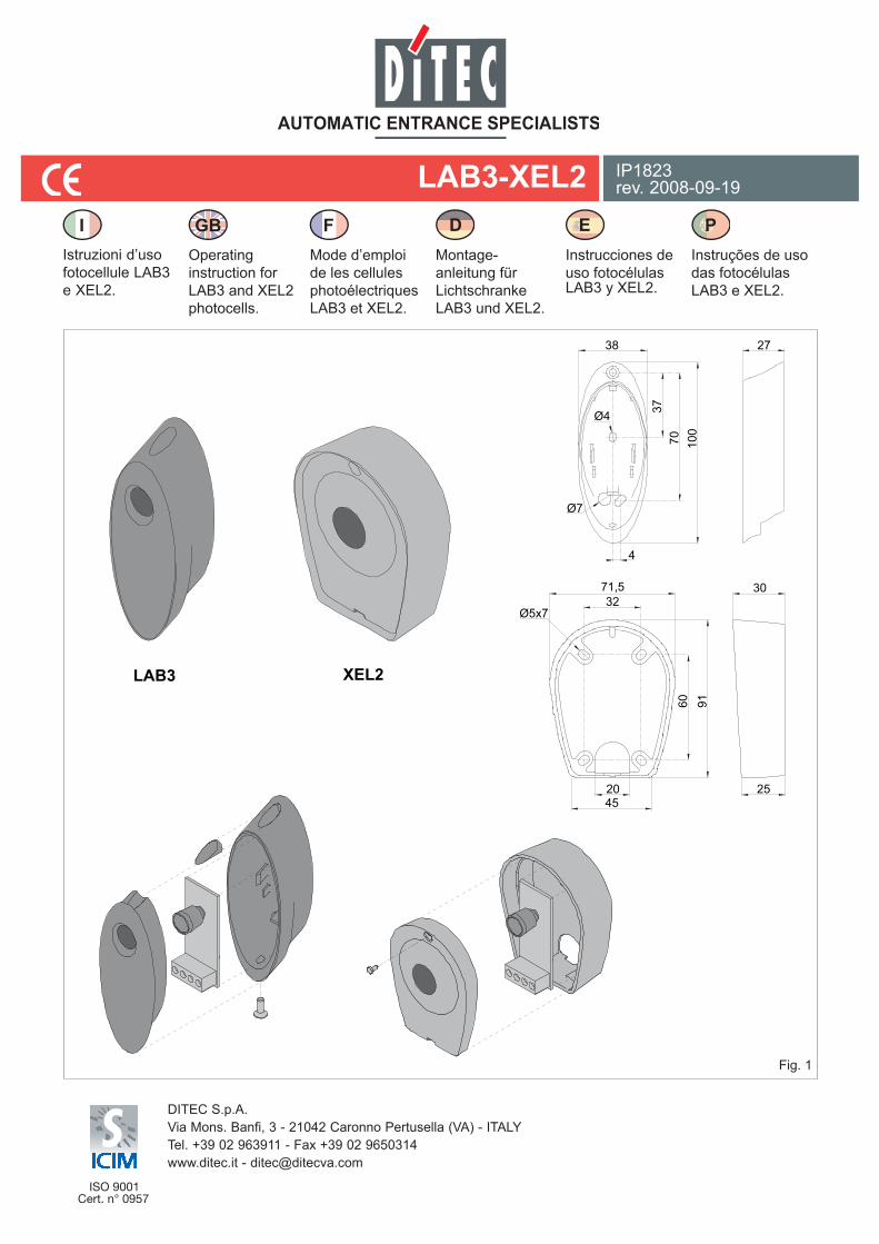
Istruzioni d’uso fotocellule LAB3 e XEL2.
Operating instruction for LAB3 and XEL2 photocells.
Mode d’emploi de les cellules photoélectriquesLAB3 et XEL2.
Montage-anleitung für Lichtschranke LAB3 und XEL2.
Instrucciones de uso fotocélulas LAB3 y XEL2.
Instruções de uso das fotocélulas LAB3 e XEL2.
LAB3 XEL2
Fig. 1
71,532
Ø5x7
30
916070
37
100
45
38
4
27
2520
Ø4
Ø7
FGBI PED
2LAB3-XEL2 - IP1823
LAB3BS
XELZA
LAB3C
55
450
92
Ø7x12
38
24
LAB3
XEL2[XEL2 + XELCB/XELCA] [XEL2C/XELC] [XEL2 + XELCA + XELK1]
Fig. 2
Fig. 3
L1
L2
L1 = 500 [XELCB]1000 [XELCA]
L2 = 560 [XELCB]1060 [XELCA]
500
Ø22
450
450-
560
XELK127
3 LAB3-XEL2 - IP1823
Fig. 4
Tutti i diritti sono riservatiI dati riportati sono stati redatti e controllati con la massima cura. Tuttavia non possiamo assumerci alcuna responsabilità per eventuali errori, omissioni o approssimazioni dovute ad esigenze tecniche o grafiche.
All right reservedAll data and specifications have been drawn up and checked with the greatest care. The manufacturer cannot however take any responsibility for eventual errors, ommisions or incomplete data due to technical or illustrative purposes.
Touts droits reservésLes informations mentionnées dans ce catalogue ont été controlées avec la plus grande attention. Toutefois, nous déclinons toute re-sponsabilité en cas d’erreurs, omissions ou approximations dépendant d’exigences techniques ou graphiques.
Alle Rechte vorbehaltenDie wiedergegebenen Daten wurden mit höchster Sorgfalt zusammengestellt und überprüft. Es kann jedoch keinerlei Verantwor-tung für eventuelle Fehler, Auslassungen oder Näherungen, die technischen oder graphischen Notwendigkeiten zuzuschreiben sind, übernommen werden.
Todos los derechos son reservadosLos datos que se indican han sido redactados y controlados con la màxima atenciòn. Sin embargo no podemos asumir ninguna responsabilidad por eventuales errores, omisiones o aproximaciones debidas a exigencias técnicas o gràficas.
Todos os direitos são reservadosOs dados indicados foram redigidos e controlados com o máximo cuidado. Contudo, não podemos assumir qualquer responsabilidade por eventuais erros, omissões ou aproximações devidas a exigências técnicas ou gráficas.
0 1
- + 24 V
TX
0
JP1
1
- + 24 V
RX
LED
RX
D
C
4LAB3-XEL2 - IP1823
AVVERTENZE GENERALI PER LA SICUREZZAIl presente manuale di installazione è rivolto esclusivamente a personale professionalmente competente. Leggere attentamente
le istruzioni prima di iniziare l’installazione del prodotto. Una errata instal-lazione può essere fonte di pericolo. I materiali dell’imballaggio (plastica, polistirolo, ecc.) non vanno dispersi nell’ambiente e non devono essere lasciati alla portata dei bambini in quanto potenziali fonti di pericolo. Prima di iniziare l’installazione verificare l’integrità del prodotto. Per l’eventuale riparazione o sostituzione dei prodotti dovranno essere uti-lizzati esclusivamente ricambi originali. E’ necessario conservare queste istruzioni e trasmetterle ad eventuali subentranti nell’uso dell’impianto.
1. DATI TECNICIAlimentazione 24 V= / 24 V~Assorbimento 50 mA maxPortata 30 m maxUscita contatto N.C. 24 V= ~ / 1ATemperatura -20° C / +55° CGrado di protezione IP44
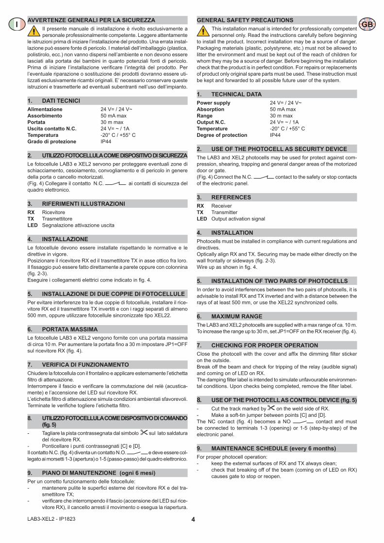
2. UTILIZZO FOTOCELLULA COME DISPOSITIVO DI SICUREZZALe fotocellule LAB3 e XEL2 servono per proteggere eventuali zone di schiacciamento, cesoiamento, convogliamento e di pericolo in genere della porta o cancello motorizzati. (Fig. 4) Collegare il contatto N.C. ai contatti di sicurezza del quadro elettronico.
3. RIFERIMENTI ILLUSTRAZIONIRX RicevitoreTX TrasmettitoreLED Segnalazione attivazione uscita
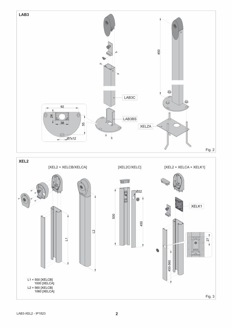
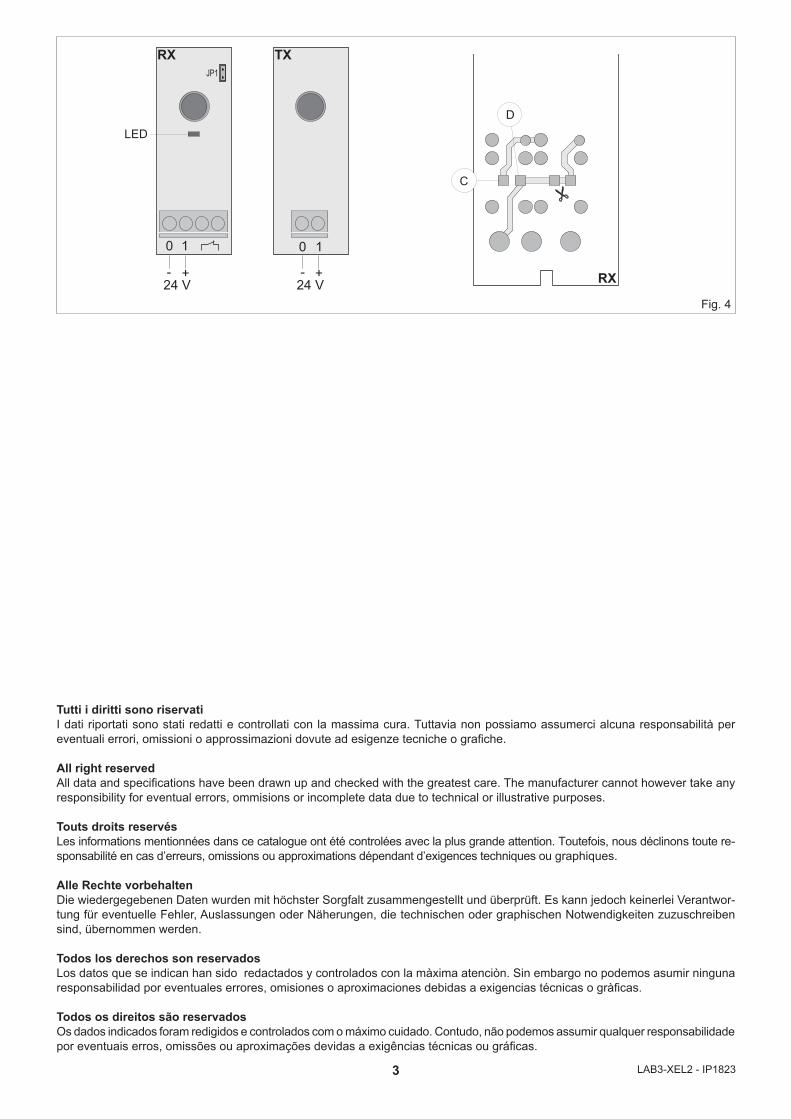
4. INSTALLAZIONELe fotocellule devono essere installate rispettando le normative e le direttive in vigore.Posizionare il ricevitore RX ed il trasmettitore TX in asse ottico fra loro. Il fissaggio può essere fatto direttamente a parete oppure con colonnina (fig. 2-3). Eseguire i collegamenti elettrici come indicato in fig. 4.
5. INSTALLAZIONE DI DUE COPPIE DI FOTOCELLULEPer evitare interferenze tra le due coppie di fotocellule, installare il rice-vitore RX ed il trasmettitore TX invertiti e con i raggi separati di almeno 500 mm, oppure utilizzare fotocellule sincronizzate tipo XEL22.
6. PORTATA MASSIMALe fotocellule LAB3 e XEL2 vengono fornite con una portata massima di circa 10 m. Per aumentare la portata fino a 30 m impostare JP1=OFF sul ricevitore RX (fig. 4).
7. VERIFICA DI FUNZIONAMENTOChiudere la fotocellula con il frontalino e applicare esternamente l’etichetta filtro di attenuazione. Interrompere il fascio e verificare la commutazione del relè (acustica-mente) e l’accensione del LED sul ricevitore RX. L’etichetta filtro di attenuazione simula condizioni ambientali sfavorevoli. Terminate le verifiche togliere l’etichetta filtro.
8. UTILIZZO FOTOCELLULA COME DISPOSITIVO DI COMANDO (fig. 5)
- Tagliare la pista contrassegnata dal simbolo sul lato saldatura del ricevitore RX.
- Ponticellare i punti contrassegnati [C] e [D].Il contatto N.C. (fig. 4) diventa un contatto N.O. e deve essere col-legato ai morsetti 1-3 (apertura) o 1-5 (passo-passo) del quadro elettronico.
9. PIANO DI MANUTENZIONE (ogni 6 mesi)Per un corretto funzionamento delle fotocellule:- mantenere pulite le superfici esterne del ricevitore RX e del tra-
smettitore TX;- verificare che interrompendo il fascio (accensione del LED sul rice-
vitore RX), il cancello arresti il movimento o esegua la riapertura.
GENERAL SAFETY PRECAUTIONSThis installation manual is intended for professionally competent personnel only. Read the instructions carefully before beginning
to install the product. Incorrect installation may be a source of danger. Packaging materials (plastic, polystyrene, etc.) must not be allowed to litter the environment and must be kept out of the reach of children for whom they may be a source of danger. Before beginning the installation check that the product is in perfect condition. For repairs or replacements of product only original spare parts must be used. These instruction must be kept and forwarded to all possible future user of the system.
1. TECHNICAL DATAPower supply 24 V= / 24 V~Absorption 50 mA maxRange 30 m maxOutput N.C. 24 V= ~ / 1ATemperature -20° C / +55° CDegree of protection IP44
2. USE OF THE PHOTOCELL AS SECURITY DEVICEThe LAB3 and XEL2 photocells may be used for protect against com-pression, shearing, trapping and general danger areas of the motorized door or gate. (Fig. 4) Connect the N.C. contact to the safety or stop contacts of the electronic panel.
3. REFERENCESRX ReceiverTX TransmitterLED Output activation signal
4. INSTALLATIONPhotocells must be installed in compliance with current regulations and directives.Optically align RX and TX. Securing may be made either directly on the wall frontally or sideways (fig. 2-3).Wire up as shown in fig. 4.
5. INSTALLATION OF TWO PAIRS OF PHOTOCELLSIn order to avoid interferences between the two pairs of photocells, it is advisable to install RX and TX inverted and with a distance between the rays of at least 500 mm, or use the XEL22 synchronized cells.
6. MAXIMUM RANGEThe LAB3 and XEL2 photocells are supplied with a max range of ca. 10 m.To increase the range up to 30 m, set JP1=OFF on the RX receiver (fig. 4).
7. CHECKING FOR PROPER OPERATIONClose the photocell with the cover and affix the dimming filter sticker on the outside.Break off the beam and check for tripping of the relay (audible signal) and coming on of LED on RX.The damping filter label is intended to simulate unfavourable environmen-tal conditions. Upon checks being completed, remove the filter label.
8. USE OF THE PHOTOCELL AS CONTROL DEVICE (fig. 5)- Cut the track marked by on the weld side of RX.- Make a soft-tin jumper between points [C] and [D].The NC contact (fig. 4) becomes a NO contact and must be connected to terminals 1-3 (opening) or 1-5 (step-by-step) of the electronic panel.
9. MAINTENANCE SCHEDULE (every 6 months)For proper photocell operation:- keep the external surfaces of RX and TX always clean;- check that breaking off of the beam (coming on of LED on RX)
causes gate to stop or reopen.
I GB
5 LAB3-XEL2 - IP1823
CONSIGNES GENERALES DE SECURITECette notice d’installation est destinée exclusivement aux pro-fessionels qualifiés. Lire attentivement les instructions avant de
procéder à l’installation du produit. Une installation erronée peut être source de danger. Les materiaux de l’emballage (plastique, polystyréne, etc ne doivent pas être abandonnés dand la nature et ne doivent pas être laissés à la portée des enfants, car ils sont une source potentielle de danger. Avant de procéder à l’installation, vérifier l’integrité du produit.En cas de réparation ou de remplacement des produits, les piéces de rechange originales doivent impérativement être utilisées. Il est indi-spensable de conserver ces instructions et de les transmettre à d’autres utilisateurs éventuels de ce systéme.
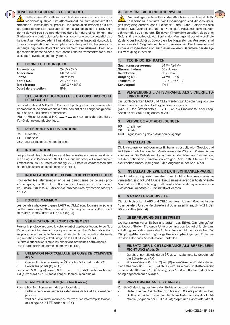
1. DONNEES TECHNIQUESAlimentation 24 V= / 24 V~Absorption 50 mA maxPortée 30 m maxSortie N.C. 24 V= ~ / 1ATempérature -20° C / +55° CDegré de protection IP44
2. UTILISATION PHOTOCELLULE EN GUISE DISPOSITIF DE SÉCURITÉ
Les photocellules LAB3 et XEL2 servent à protéger les zones éventuelles d’écrasement, de cisaillement, d’entraînement et de danger en général, de la porte ou du portail automatisés.(Fig. 4) Relier le contact N.C. aux contacts de sécurité ou d’arrêt du tableau electronique.
3. RÉFÉRENCES ILLUSTRATIONSRX RécepteurTX EmetteurLED Signalisation activation de sortie
4. INSTALLATIONLes photocellules doivent être installées selon les normes et les directi-ves en vigueur. Positionner RX et TX sur leur axe optique. La fixation peut s’effectuer au mur ou latéralement (fig. 2-3). Effectuer les raccordements électriques selon les indications de la fig. 4.
5. INSTALLATION DE DEUX PAIRES DE PHOTOCELLULESPour éviter les interférences entre les deux paires de cellules pho-toélectriques, installer RX et TX intervertis et avec les rayons distants d’au moins 500 mm, ou utiliser des photocellules synchronisées type XELL22.
6. PORTÉE MAXIMUMLes cellules photoélectriques LAB3 et XEL2 sont fournies avec une portée maximum de 10 mètres environ. Pour augmenter la portée jusqu’à 30 mètres, mettre JP1=OFF de RX (fig. 4).
7. VÉRIFICATION DU FONCTIONNEMENTFermer la photocellule avec le volet avant et appliquer l’étiquette du filtre d’atténuation à l’extérieur. La plaque avant et le filtre d’atténuation étant en place, interrompre le faisceau et vérifier la commutation du relais (signalisation sonore) et l’allumage de la LED située sur RX.Le filtre d’atténuation simule les conditions ambiantes défavorables.Une fois les contrôles terminés, enlever le filtre.
8. UTILISATION PHOTOCELLULE EN GUISE DE COMMANDE (fig. 5)
- Couper la piste repérée par sur le côté soudure de RX.- Ponter les points [C] et [D].Le contact N.C. (fig. 4) devient N.O. et doit être relié aux bornes 1-3 (ouverture) ou 1-5 (pas à pas) du tableau electonique.
9. PLAN D’ENTRETIEN (tous les 6 mois)Pour le bon fonctionnement des photocellules:- veiller à ce que les surfaces extérieures de RX et TX soient bien
propres;- vérifier que le portail s’arrête ou rouvre si l’on interrompt le faisceau
(allumage de la LED située sur RX).
ALLGEMEINE SICHERHEITSHINWEISEDas vorliegende Installationshandbuch ist ausschliesslich für Fachpersonal bestimmt. Vor Einbaubeginn sind die Anweisun-
gen sorgfältig durchzulesen. Falscher Einbau kann Gefahr mit sich bringen. Das Verpackunsmaterial (Kunststoff, Polystyrol, usw.) ist vor-schriftsmäßig zu entsorgen. Es ist von Kindern fernzuhalten, da es eine Gefahr für sie bedeutet. Vor Beginn der Montage ist der einwandfreie Zustand des Produkts zu überprüfen. Bei Reparatur und Austausch sind ausschliesslich Originalersatzteile zu verwenden. Die Hinweise sind sicher aufzubewahren und auch allen weiteren Benutzern der Anlage zur Verfügung zu stellen.
1. TECHNISCHEN DATENSpannungsversorgung 24 V= / 24 V~Stromaufnahme 50 mA maxReichtweite 30 m maxAufgang N.C. 24 V= ~ / 1ATemperatur -20° C / +55° CSchutzgrad IP44
2. VERWENDUNG LICHTSCHRANKE ALS SICHERHEITS-EINRICHTUNG
Die Lichtschranken LAB3 und XEL2 werden zur Absicherung von Ge-fahrenbereichen an kraftbetätigten Toren eingesetzt.(Abb. 4) Den Öffnerkontakt an die Sicherheits- oder Stop-Kontakte der Steuerung anschließen.
3. VERWEISE AUF ABBILDUNGENRX EmpfängerTX SenderLED Signalisierung des aktivierten Ausgangs
4. INSTALLATIONDie Lichtschranken müssen unter Einhaltung der geltenden Gesetze und Richtlinien installiert werden. Positionieren Sie RX und TX einer Achse zueinander. Die Befestigung kann direkt an der Wand am Pfosten oder mit den optionalen Standsäulen erfolgen (Abb. 2-3). Stellen Sie die elektrischen Anschlüsse gemäß den Angaben in der Abb. 4 her.
5. INSTALLATION ZWEIER LICHTSCHRANKENPAAREUm Überlagerung zwischen den zwei Lichtaschrankenpaaren zu vermeiden, sind RX und TX über Kreuz zu installieren der Abstand sollte Mindestens 500 mm betragen. Alternativ können die synchronisierten Lichtschrankenpaare XEL22 installiert werden.
6. MAXIMALE REICHWEITEDie Lichtschranken LAB3 und XEL2 werden mit einer Reichweite von 10 m geliefert. Um die Reichweite auf 30 m zu erhöhen, JP1=OFF des RX einstellen (Abb. 4).
7. ÜBERPRÜFUNG DES BETRIEBSLichtschranken verschließen und außen das Etikett Dämpfungsfilter aufkleben. Stellen Sie durch Unterbrechung des Lichtstrahls die Um-schaltung des Relais sowie das Aufleuchten der LED auf RX sicher. Der Dämpfungsfilter simuliert ungünstige Umgebungsbedingungen. Entfernen Sie den Filter nach Abschluss der Kontrollen.
8. EINSATZ DER LICHTSCHRANKE ALS BEFEHLSEIN-RICHTUNG (Abb. 5)
- Durchtrennen Sie die durch gekennzeichnete Leiterbahn auf der Lötseite von RX.
- Brücken Sie die Punkte [C] und [D] indem Sie einen Draht auflöten.Der Öffnerkontakt (Abb. 4) wird zu einem Schließerkontakt muss an die Klemmen 1-3 (Öffnung) oder 1-5 (Schrittbetrieb) der Steu-erung angeschlossen werden.
9. WARTUNGSPLAN (alle 6 Monate)Zur Gewährleistung des korrekten Betriebs der Lichtschranken:- Halten Sie die Oberflächen von RX und TX stets perfekt sauber;- Stellen sie sicher, dass das Tor beim Unterbrechen des Licht-
strahls (Angehen der LED auf RX) stoppt und sich wieder öffnet.
F D
6LAB3-XEL2 - IP1823
ADVERTENCIAS GENERALES DE SEGURIDADEl presente manual de instalaciòn està destinado exclusivamente a professionales cualificados. Leer atentamente las instrucciones
antes de comenzar la instalaciòn del producto. Una instalaciòn incorrecta puede ser causa de peligro. El material de embalaje (plàstico, poliestirol, etc.) debe desecharse sin causar daño al medio ambiente y mantener-se fuera del alcance de los niños, porque es una potencial fuente de peligro. Antes de comenzar la instalaciòn verificar que el producto esté íntegro. Para cualquier reparaciòn o sustituciòn del producto, utilizar exclusivamente repuestos originales. Conservar estas instrucciones y entregarlas a futuros usuarios.
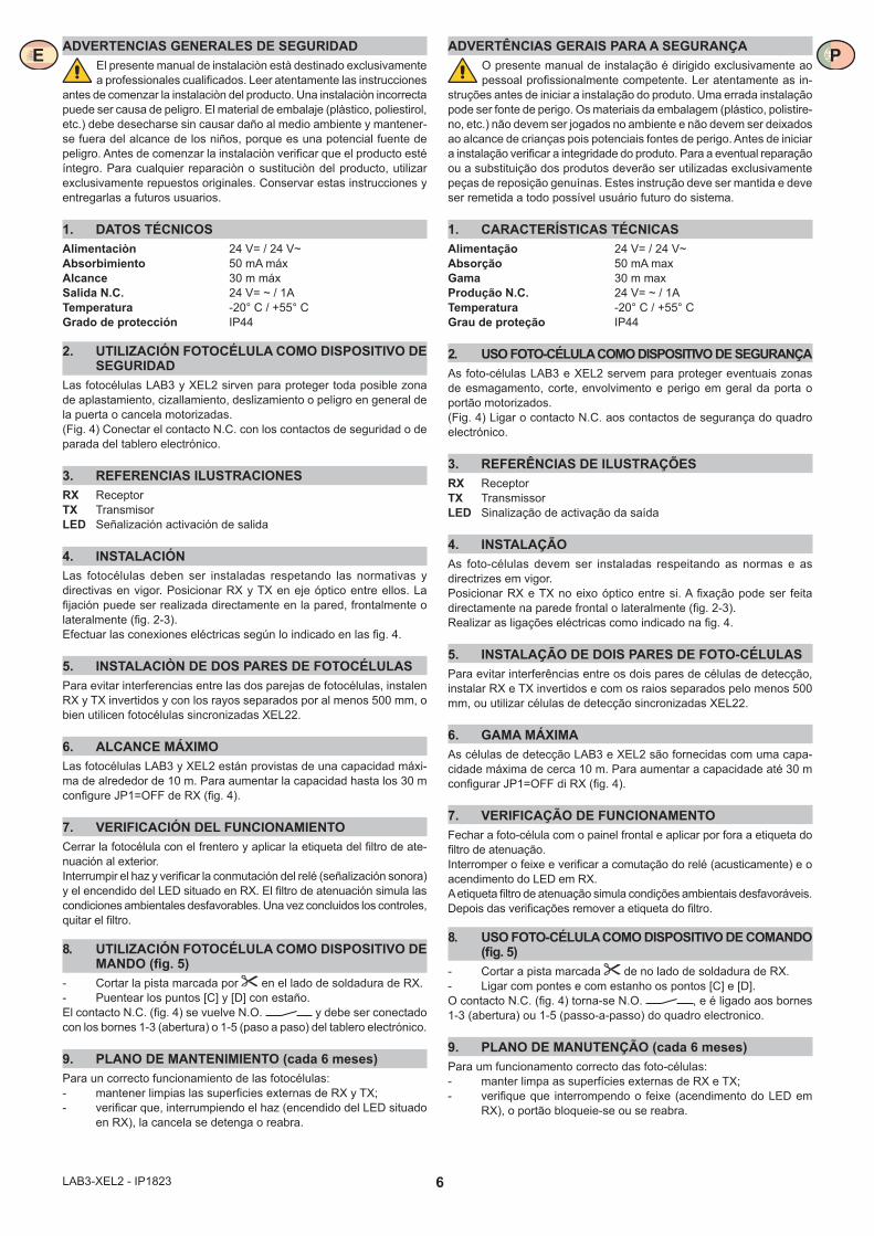
1. DATOS TÉCNICOSAlimentaciòn 24 V= / 24 V~Absorbimiento 50 mA máxAlcance 30 m máxSalida N.C. 24 V= ~ / 1ATemperatura -20° C / +55° CGrado de protección IP44
2. UTILIZACIÓN FOTOCÉLULA COMO DISPOSITIVO DE SEGURIDAD
Las fotocélulas LAB3 y XEL2 sirven para proteger toda posible zona de aplastamiento, cizallamiento, deslizamiento o peligro en general de la puerta o cancela motorizadas.(Fig. 4) Conectar el contacto N.C. con los contactos de seguridad o de parada del tablero electrónico.
3. REFERENCIAS ILUSTRACIONESRX ReceptorTX TransmisorLED Señalización activación de salida
4. INSTALACIÓNLas fotocélulas deben ser instaladas respetando las normativas y directivas en vigor. Posicionar RX y TX en eje óptico entre ellos. La fijación puede ser realizada directamente en la pared, frontalmente o lateralmente (fig. 2-3).Efectuar las conexiones eléctricas según lo indicado en las fig. 4.
5. INSTALACIÒN DE DOS PARES DE FOTOCÉLULASPara evitar interferencias entre las dos parejas de fotocélulas, instalen RX y TX invertidos y con los rayos separados por al menos 500 mm, o bien utilicen fotocélulas sincronizadas XEL22.
6. ALCANCE MÁXIMOLas fotocélulas LAB3 y XEL2 están provistas de una capacidad máxi-ma de alrededor de 10 m. Para aumentar la capacidad hasta los 30 m configure JP1=OFF de RX (fig. 4).
7. VERIFICACIÓN DEL FUNCIONAMIENTOCerrar la fotocélula con el frentero y aplicar la etiqueta del filtro de ate-nuación al exterior. Interrumpir el haz y verificar la conmutación del relé (señalización sonora) y el encendido del LED situado en RX. El filtro de atenuación simula las condiciones ambientales desfavorables. Una vez concluidos los controles, quitar el filtro.
8. UTILIZACIÓN FOTOCÉLULA COMO DISPOSITIVO DE MANDO (fig. 5)
- Cortar la pista marcada por en el lado de soldadura de RX.- Puentear los puntos [C] y [D] con estaño.El contacto N.C. (fig. 4) se vuelve N.O. y debe ser conectado con los bornes 1-3 (abertura) o 1-5 (paso a paso) del tablero electrónico.
9. PLANO DE MANTENIMIENTO (cada 6 meses)Para un correcto funcionamiento de las fotocélulas:- mantener limpias las superficies externas de RX y TX;- verificar que, interrumpiendo el haz (encendido del LED situado
en RX), la cancela se detenga o reabra.
ADVERTÊNCIAS GERAIS PARA A SEGURANÇAO presente manual de instalação é dirigido exclusivamente ao pessoal profissionalmente competente. Ler atentamente as in-
struções antes de iniciar a instalação do produto. Uma errada instalação pode ser fonte de perigo. Os materiais da embalagem (plástico, polistire-no, etc.) não devem ser jogados no ambiente e não devem ser deixados ao alcance de crianças pois potenciais fontes de perigo. Antes de iniciar a instalação verificar a integridade do produto. Para a eventual reparação ou a substituição dos produtos deverão ser utilizadas exclusivamente peças de reposição genuínas. Estes instrução deve ser mantida e deve ser remetida a todo possível usuário futuro do sistema.
1. CARACTERÍSTICAS TÉCNICASAlimentação 24 V= / 24 V~Absorção 50 mA maxGama 30 m maxProdução N.C. 24 V= ~ / 1ATemperatura -20° C / +55° CGrau de proteção IP44
2. USO FOTO-CÉLULA COMO DISPOSITIVO DE SEGURANÇAAs foto-células LAB3 e XEL2 servem para proteger eventuais zonas de esmagamento, corte, envolvimento e perigo em geral da porta o portão motorizados.(Fig. 4) Ligar o contacto N.C. aos contactos de segurança do quadro electrónico.
3. REFERÊNCIAS DE ILUSTRAÇÕESRX ReceptorTX TransmissorLED Sinalização de activação da saída
4. INSTALAÇÃOAs foto-células devem ser instaladas respeitando as normas e as directrizes em vigor.Posicionar RX e TX no eixo óptico entre si. A fixação pode ser feita directamente na parede frontal o lateralmente (fig. 2-3).Realizar as ligações eléctricas como indicado na fig. 4.
5. INSTALAÇÃO DE DOIS PARES DE FOTO-CÉLULASPara evitar interferências entre os dois pares de células de detecção, instalar RX e TX invertidos e com os raios separados pelo menos 500 mm, ou utilizar células de detecção sincronizadas XEL22.
6. GAMA MÁXIMAAs células de detecção LAB3 e XEL2 são fornecidas com uma capa-cidade máxima de cerca 10 m. Para aumentar a capacidade até 30 m configurar JP1=OFF di RX (fig. 4).
7. VERIFICAÇÃO DE FUNCIONAMENTOFechar a foto-célula com o painel frontal e aplicar por fora a etiqueta do filtro de atenuação. Interromper o feixe e verificar a comutação do relé (acusticamente) e o acendimento do LED em RX.A etiqueta filtro de atenuação simula condições ambientais desfavoráveis. Depois das verificações remover a etiqueta do filtro.
8. USO FOTO-CÉLULA COMO DISPOSITIVO DE COMANDO (fig. 5)
- Cortar a pista marcada de no lado de soldadura de RX.- Ligar com pontes e com estanho os pontos [C] e [D].O contacto N.C. (fig. 4) torna-se N.O. , e é ligado aos bornes 1-3 (abertura) ou 1-5 (passo-a-passo) do quadro electronico.
9. PLANO DE MANUTENÇÃO (cada 6 meses)Para um funcionamento correcto das foto-células:- manter limpa as superfícies externas de RX e TX;- verifique que interrompendo o feixe (acendimento do LED em
RX), o portão bloqueie-se ou se reabra.
E P