diseño de maquinaria de cubierta de buques, en base a una
TRANSCRIPT
DISEÑO DE MAQUINARIA DE CUBIERTA DE
BUQUES, EN BASE A UNA PROPUESTA
RAZONADA DE ARMONIZACIÓN
REGLAMENTARIA
Por
Juan Carlos Carral Couce
Tesis Doctoral 2015
DISEÑO DE MAQUINARIA DE CUBIERTA DE BUQUES, EN
BASE A UNA PROPUESTA RAZONADA DE ARMONIZACIÓN
REGLAMENTARIA
Documento de Tesis presentada a la Universidad da Coruña, en
cumplimiento de los requisitos para la obtención del título de
Doctor en Ingeniería Industrial
Por
Juan Carlos Carral Couce
Director
Dr. José Ángel Fraguela Formoso
2015


Diseño de maquinaria de cubierta de buques, en base a una
propuesta razonada de armonización reglamentaria
Esta memoria científica ha sido realizada por Juan Carlos Carral Couce y constituye la
Tesis que presenta para optar al Grado de Doctor por la Universidad da Coruña
El Autor:
Juan Carlos Carral Couce
Aprobada por el Director:
Dr. José Ángel Fraguela Formoso
Escuela Politécnica Superior
Universidad da Coruña
2015

Diseño de maquinaria de cubierta de buques, en base a una propuesta razonada de armonización reglamentaria Pág. 4
Diseño de maquinaria de cubierta de buques, en base a una propuesta razonada de armonización reglamentaria Pág. 5
Reconocimientos
Ante todo quisiera expresar mi más sincero agradecimiento a mi director Dr. José Ángel Fraguela Formoso por su paciencia, apoyo moral y motivación durante la etapa de investigación. Además de a mi director, me gustaría dar las gracias a mi hermano Luis por su conocimiento, ayuda y consejos. Su guía ha sido de gran ayuda en la redacción de esta tesis. No puedo olvidarme de mi familia, de mis padres y sobre todo de mi mujer Pilar y de mi hijo Javier, a quienes además de soportarme les robe muchas horas de su tiempo. Por último pero no menos importante dar las gracias a todos los revisores anónimos de las revistas cuyas correcciones y comentarios han ayudado a mejorar el resultado final de esta Tesis

Diseño de maquinaria de cubierta de buques, en base a una propuesta razonada de armonización reglamentaria Pág. 6

Diseño de maquinaria de cubierta de buques, en base a una propuesta razonada de armonización reglamentaria Pág. 7
Resumen
El transporte marítimo ha evolucionado en el siglo XX de la mano de una demanda creciente, hasta situarse en la vanguardia de los modos de transporte de mercancías. La aplicación de economías de escala y la liberalización de los registros de buques, han acompañado a la evolución tecnológica del sistema de transporte (buques y puertos) en un proceso continuo de reducción de costes, colocando al transporte marítimo en esa situación de competitividad. El transporte marítimo del futuro continuará demandando, en su búsqueda de competitividad, de la reducción en sus costes de explotación. En el caso concreto de los buques, esta evolución favorable se deberá producir; tanto desde la reducción en los costes de construcción, como de los costes de explotación. En el apartado de la construcción naval, los astilleros como protagonistas de esa lucha, transmiten a la industria complementaria la necesidad de fabricar equipos de alta calidad y tecnológicamente avanzados, pero a la vez con unos precios que permitan rebajar el coste total de la construcción. Los continuos avances tecnológicos y el incremento de las exigencias reglamentarias, han aumentado la seguridad y eficiencia de los buques, pero a costa de hacerlos más complejos y caros. Para los fabricantes de equipos de cubierta, la importante ayuda que representa la estandarización de los procesos de diseño y producción, choca con la necesidad de adaptar el diseño de sus equipos, a las necesidades del armador y al cumplimiento de una reglamentación, casi siempre incompleta y con numerosas contradicciones. La maquinaria de cubierta agrupa a aquellos equipos y accesorios que, por medios mecánicos, hidráulicos o eléctricos, facilitan la realización de las maniobras propias de la tripulación del buque. Su variedad es realmente numerosa; desde molinetes, chigres y cabrestantes para labores de amarre y fondeo, chigres y tambores de red especialmente resistentes para las actividades de pesca industrial, ganchos y chigres para remolque, pescantes, grúas y cabrestantes para operaciones de carga y descarga, hasta equipos para estudios oceanográficos y científicos. Todos ellos presentan una diversidad de funcionamientos y accionamientos. A esta diversidad se añaden las frecuentes fusiones entre equipos distintos, combinando sus funciones y características. Durante la navegación el buque se traslada de un puerto a otro. Cuando llega a puerto el equipo propulsor se detiene, y el buque queda sometido a las acciones de las corrientes y los vientos. Una vez fondeado o atracado para contrarrestar estas acciones debe ser sujetado al muelle, al fondo o amarrado a una o varias boyas. Esta función corresponde a los equipos de fondeo y amarre. A pesar de la importancia que estos equipos de amarre y fondeo tienen en la preservación del buque, y aunque todas las reglamentaciones tienen un mismo objetivo común y mantienen exigencias similares, también presentan diferencias notables que impiden o limitan la deseable estandarización de su diseño. La situación podría resumirse en una frase: “para cada buque se hace necesario un nuevo diseño”.

Diseño de maquinaria de cubierta de buques, en base a una propuesta razonada de armonización reglamentaria Pág. 8
Otro de los equipos de cubierta analizados, por su gran importancia para España, son los chigres de pesca de los arrastreros Su adecuado diseño y funcionamiento condiciona la operatividad del buque. Para este equipo la reglamentación existente es casi nula, lo que podría parecer que facilitaría la necesaria estandarización. Pero como España a pesar de tener una gran flota de altura, no posee caladeros propios, sus buques y equipos deben diseñarse con la versatilidad suficiente para que puedan cambiar de un caladero a otro en función de los acuerdos comerciales alcanzados con otros países. Si consideramos los remolcadores, un elemento de gran importancia es el chigre de remolque. En la propuesta de armonización reglamentaria para los chigres de remolque, cuyo documento fue publicado unos meses antes de la propuesta de título de esta tesis, dando origen a la idea de realizar una tesis doctoral, se analizó el problema existente de la carencia y falta de uniformidad reglamentaria. En su momento se propuso un criterio armonizado que permite desarrollar una futura regulación común. Finalmente para los elementos auxiliares destinados al manejo de las líneas de maniobra, movimiento de carga, labores de pesca y remolque de los buques, el panorama apenas cambia. A pesar de su importancia, su consideración como elemento auxiliar hace que su normativa regulatoria se encuentre dispersa y presente discrepancias notables. Vistas todas estas carencias, el objetivo de esta tesis es: Estudiar las diferentes reglamentaciones y/o necesidades actualmente existentes para la maquinaria de cubierta de los buques, proceder a su comparación y proponer unas normas de diseño que signifiquen un punto de encuentro entre todas ellas. Para ello, sin ánimo de exclusión de otras, se han considerado tres fuentes documentales: La primera gran fuente documental corresponde a las Sociedades de Clasificación. El tratamiento que las principales Sociedades de Clasificación consideradas; American Bureau of Shipping (ABS), Bureau Veritas (BV) , Det Norske Veritas (DNV), Germanicher Lloyd (GL), Rina (RN) y Lloyd´s Register of Shipping (LR), dan a la operación y a las especificaciones para el diseño de la maquinaria de cubierta son bastante dispares. Por otra parte, la International Association of Classification Societies (IACS), armoniza sólo parcialmente las exigencias de las Sociedades de Clasificación desde el punto de vista operativo, sin establecer un documento armonizado para el diseño de los equipos. La segunda vía corresponde a la International Standard Organisation (ISO), formada por las federaciones nacionales de más de 156 países, incluyendo una buena parte de los países europeos. La ISO ha desarrollado sus normas de aplicación al caso en estudio mediante el Comité técnico ISO – TC 8, correspondiente a la Construcción Naval y Estructuras Marinas (Shipbuilding and marine structure). Las normas ISO, aceptadas como EN-ISO por el Comité Europeo de Normalización (European Committe for Standardization), cubren una gran parte de aspectos no tratados por las Sociedades de Clasificación. A través de su estudio y comparación, son una gran ayuda para la propuesta de un criterio armonizado que posibilite el desarrollo de una

Diseño de maquinaria de cubierta de buques, en base a una propuesta razonada de armonización reglamentaria Pág. 9
futura regulación común, que conduzca a un relevante ahorro en el diseño y producción de los equipos. La tercera vía considerada corresponde a los reglamentos de terminales y operadores, tales como la Oil Companies International Marine Forum (OCIMF), de gran importancia en el caso del amarre de buques, la International Safety Guide for Oil Tankers and Terminals (ISGOTT) y la Organización Marítima Internacional (OMI), así como a los datos aportados por Asociaciones y evidentemente los documentos publicados por autores de reconocido prestigio sobre la materia. El resultado de los estudios es una normativa en cuanto a las características de los materiales, hipótesis de cargas formuladas, métodos de cálculo a emplear, especificidades para la fabricación y el montaje, pruebas y ensayos tanto en taller como en el propio buque y condiciones de funcionamiento estandarizados para los equipos analizados. La utilización de esta armonización reglamentación hará posible la estandarización que contribuirá a reducir el coste de fabricación de los equipos señalados y a aumentar la competitividad de la industria complementaria de la Construcción Naval europea. Palabras clave: Buques, estandarización, armonización reglamentaria, maquinaria de cubierta, diseño, pesca de arrastre, chigres.

Diseño de maquinaria de cubierta de buques, en base a una propuesta razonada de armonización reglamentaria Pág. 10
Diseño de maquinaria de cubierta de buques, en base a una propuesta razonada de armonización reglamentaria Pág. 11
Índice
Reconocimientos
Resumen
Capítulo 1: Introducción
Capítulo 2: Objetivos
Capítulo 3: Discusión General. Coherencia y unidad de los artículos
Capítulo 4: Metodología
Capítulo 5: Resultados
5.1. Anchor windlasses: A design proposal to standa rdise regulations
Summary
Notation
1. Introduction
1.1. Current regulations
2. Comparing a selections of relevant regulations
3. Proposal for standardization regulations and working hypotheses
3.1. Proposal for more cohesive regulations
3.2. Working hypotheses
4. Design process for windlass based on more cohesive regulations
4.1. Windlass types
4.2. Operating system: Transmission ratio
4.3. Average and instantaneous power of the windlass
4.4. Geometry and dimensions for the cable-lifter on the warping end
4.5. Brake type and dimensions

Diseño de maquinaria de cubierta de buques, en base a una propuesta razonada de armonización reglamentaria Pág. 12
5. Conclusions
6. References
Appendix I
5.2. Standardizing the design and production of moo ring winches through more cohesive regulations
Summary
1. Introduction
2. Comparing existing regulations
2.1. Operating regulations
2.2 Design and manufacturing regulations
3. Proposal for harmonising regulations
3.1. Proposal to harmonise regulation exigencies
3.2. Working hypothesis
4. Proposal for calculating component design
4.1. Input data
4.2. Drum dimensions
4.3. Warp end. Dimensions and shape
4.4. Type of prime mover gear ratio
4.5. Power needed for the mooring winch
4.6. Determining the brake
Conclusions
References
Apendix 1
5.3. Fishing grounds´ influence on trawler winch de sign
Abstract
1. Introduction
2. Fishing grounds that Spanish fleet of trawlers most commonly frequent,
adapting the vessel and its gear to the peculiarities of each ground
3. Design parameters
3.1. Drum capacity
3.1.1. Line length and diameter
3.1.2. Bridle length and diameter

Diseño de maquinaria de cubierta de buques, en base a una propuesta razonada de armonización reglamentaria Pág. 13
3.2. Average, nominal and maximum traction
3.3. Hauling speed
4. Operation: Determining the necessary power
5. Comparing operational values in ISO guidelines with the working demands on
the fleet
6. Conclusions
Notation
References
5.4. Diseño armonizado de motones, pastecas y cuade rnales para el manejo de líneas de acero o sintéticas de elevado módulo (HMP E) en buques
Resumen
1. Introducción
2. Criterio de armonización para el diseño de los motones y pastecas para su
empleo a bordo.
2.1. Criterios de armonización
2.2. Criterios de diseño
2.2.1. Definición del cable
2.2.2 Definición del Motón
2.2.3. Criterio Funcional
2.2.4. Criterio de la capacidad resistente
2.3. Propuesta armonizadora
3. Adaptación de la polea al uso de líneas HMPE (High Modulus Polyethylene
Fibre)
Conclusiones
Bibliografía
Notación
5.5. El chigre de remolque en las maniobra de altur a y de escolta: propuesta de armonización en sus parámetros de diseño.
Resumen
1. Introducción
2. El chigre de Remolque

Diseño de maquinaria de cubierta de buques, en base a una propuesta razonada de armonización reglamentaria Pág. 14
3. Reglamentación existente
4. Propuesta de armonización reglamentaria. Propuesta de cálculo
4.1. Parámetros de diseño del chigre-Calculo previo de la carga de rotura del
cable.
4.2. Dimensiones del carretel
4.2.1. Capacidad de cable
4.2.2. Geometría del carretel
4.3. Tracción del chigre
4.3.1. Tracción nominal
4.3.2. Tracción al freno
4.4. Velocidad de cobrado y largado
5. Conclusiones
Bibliografía
Capítulo 6. Conclusiones
6.1. Conclusiones de los artículos
6.2. Conclusiones Generales de la tesis
Capítulo 7. Bibliografía
7.1. Bibliografía por artículo
7.2. Bibliografía común
Capítulo 8. Apéndice

Diseño de maquinaria de cubierta de buques, en base a una propuesta razonada de armonización reglamentaria Pág. 15
1. INTRODUCCION

Diseño de maquinaria de cubierta de buques, en base a una propuesta razonada de armonización reglamentaria Pág. 16

Diseño de maquinaria de cubierta de buques, en base a una propuesta razonada de armonización reglamentaria Pág. 17
Capítulo 1: Introducción
La falta de uniformidad en la normativa que regula el diseño de los equipos de cubierta en los buques es un viejo problema que hoy en día sigue sin resolver. A esta falta de uniformidad, también hay que añadir la carencia de normativa en muchos aspectos. Esta tesis, comienza analizando las diferentes reglamentaciones que actualmente existen para la maquinaria de cubierta y elementos auxiliares de los buques para, a continuación, proponer una normativa armonizada que cubra todos los aspectos de su diseño. Para ello se compara la reglamentación existente de aplicación de la organización marítima mundial (OMI), los reglamentos de las Sociedades de Clasificación (SSCC), de la International Asociation Clasification Societates (IACS), de las asociaciones gremiales, tales como: la Oil Companies International Marine Forum (OCIMF), la International Safety Guide for Oil Tankers and Terminals (ISGOTT) y de las entidades internacionales de estandarización (ISO, UNE, DIN, ASTM). En base a los estudios realizados, se propone una normativa que significa un punto de encuentro entre todas ellas en cuanto a; características de los materiales, hipótesis de cargas formuladas, métodos de cálculo a emplear, especificidades para la fabricación y el montaje, pruebas y ensayos, tanto en taller como en el propio barco, y condiciones de funcionamiento estandarizados. Esta armonización regulatoria contribuirá, sin duda, a la estandarización, necesaria para reducir el coste de fabricación de los equipos analizados y así aumentar la competitividad de la industria complementaria de la Construcción Naval europea mediante los ahorros propios de la producción a pequeña escala. Además la estandarización funcional reducirá el tiempo de aprendizaje en la utilización de los equipos aumentando la seguridad activa del buque. La tesis se estructura en 7 capítulos. El Capítulo 1, Introducción, explica las razones que motivan la realización de los artículos, la estructura de la tesis y proporciona una visión general de la temática a tratar. Los principales objetivos se definen en el Capítulo 2, Objetivos. En el Capítulo 3, Discusión general; Coherencia y unidad de los artículos, se justifica la elección de los temas abordados y su forma de análisis, de modo su aportación sea coherente con los objetivos generales de la tesis. El Capítulo 4, Metodología explica el procedimiento de trabajo seguido para obtener los objetivos propuestos. El Capítulo 5, Resultados, incluye las publicaciones en revistas científicas con un alto factor de impacto, indexadas en la lista del ámbito correspondiente del Journal Citation Reports que constituyen el núcleo de investigación de la tesis. En el artículo Anchor windlasses: A design proposal to standardise regulations, (apartado 5.1). publicado en International Journal of Maritime Engineering, una vez expuesta la necesidad de reducir los costes de los buques, se enumeran los reglamentos que deben considerarse para el diseño de los equipos de fondeo. Tras la comparación de la reglamentación existente se hace una propuesta de diseño, construcción y condiciones operacionales para el elemento principal del sistema de fondeo, el molinete de anclas. Todo ello con el objetivo de ayudar a alcanzar la deseable estandarización, que conduzca a los ahorros en el diseño, fabricación y
Diseño de maquinaria de cubierta de buques, en base a una propuesta razonada de armonización reglamentaria Pág. 18
mantenimiento, propios de las economías de escala. En el artículo, Standardizing the design and production of mooring winches through more cohesive regulations, (apartado 5.2), publicado en International Journal of Maritime Engineering, se analiza la reglamentación existente para los chigres de amarre, buscando los puntos comunes, para a continuación proponer un reglamento que unifique y complemente todos los contenidos. Con los mismos objetivos que los indicados para los equipos de fondeo, esta propuesta armonizada de reglamento se aplica al diseño, construcción y operatividad de los chigres de amarre En el artículo, Fishing grounds´ influence on trawler winch design, (apartado 5.3) publicado en Ocean Engineering, se determina el tipo de chigre de pesca más adecuado para operar en los distintos caladeros internacionales en los que faena la flota española de pesca de arrastre. De esta manera, para cada zona de pesca, se establece la relación entre los parámetros de diseño del chigre de pesca y la profundidad de trabajo del aparejo. Finalmente, se define una propuesta armonizada para su diseño. En el artículo, Diseño armonizado de motones, pastecas y cuadernales para el manejo de líneas de acero o sintéticas de elevado módulo (HMPE) en buques, (apartado 5.4), publicado en Dyna, Ingeniería e Industria, se compara la reglamentación existente para los motones, pasteas y cuadernales. A continuación se realiza una propuesta de diseño, que conjugando y complementado toda la normativa la armonice, ayudará a alcanzar la deseable estandarización necesaria, para conseguir los ahorros propios de la producción a pequeña/media escala. El artículo, El chigre de remolque en las maniobra de altura y de escolta: propuesta de armonización en sus parámetros de diseño, (apartado 5.5), se incluye a modo informativo y complementario. A pesar de ser el tema que dio origen a la idea de realizar un conjunto de artículos sobre armonización reglamentaria del diseño de equipos de cubierta, reglamentariamente no forma parte de la tesis. Publicado en Dyna, Ingeniería e Industria, sigue el mismo procedimiento que en los casos anteriores; la comparación previa de la reglamentación existente y la propuesta final de una normativa armonizada para su diseño. El Capítulo 6 se corresponde a la Conclusiones, tanto generales de la tesis, como las particulares de cada uno de los artículos. Y finalmente el Capítulo 7, Bibliografia contiene la documentación empleada para cada uno de los artículos y la considerada común para la tesis, por emplearse en más de un artículo.

Diseño de maquinaria de cubierta de buques, en base a una propuesta razonada de armonización reglamentaria Pág. 19
2. OBJETIVOS

Diseño de maquinaria de cubierta de buques, en base a una propuesta razonada de armonización reglamentaria Pág. 20
Diseño de maquinaria de cubierta de buques, en base a una propuesta razonada de armonización reglamentaria Pág. 21
Capítulo 2: Objetivos
Una vez analizada la situación actual de la normativa reglamentaria para el diseño de maquinaria de cubierta, y detectadas las notables carencias y falta de uniformidad existente, el objetivo fundamental de esta tesis es: “Proponer y difundir una normativa armonizada para el diseño de la maquinaria de cubierta de los buques en general, y en concreto de los equipos de fondeo (molinetes) chigres de amarre, chigres de pesca, chigres de remolque y elementos auxiliares (motones, pastecas y cuadernales)”.

Diseño de maquinaria de cubierta de buques, en base a una propuesta razonada de armonización reglamentaria Pág. 22

Diseño de maquinaria de cubierta de buques, en base a una propuesta razonada de armonización reglamentaria Pág. 23
3. DISCUSION GENERAL. COHERENCIA Y UNIDAD DE LOS ARTICULOS

Diseño de maquinaria de cubierta de buques, en base a una propuesta razonada de armonización reglamentaria Pág. 24
Diseño de maquinaria de cubierta de buques, en base a una propuesta razonada de armonización reglamentaria Pág. 25
Capítulo 3: Discusión General. Coherencia y unidad de la tesis
Los cuatro artículos originales que constituyen la tesis y el quinto, que se incluye a modo de complemento, están publicados en las siguientes revistas de alto interés científico incluidas en JCR (Journal Citation Reports). - IJME (International Journal of Maritime Engineering), revista que pertenece a la
Royal Institution of Naval Architects, Para 2014, esta revista estaba clasificada de 9 sobre 14. Tercil en la categoría T3. Cuartil en la categoría Q3. Factor de impacto 0,361. Factor de impacto de 5 años 0.283
- Ocean Engineering. Revista de gran prestigio del grupo editorial Elsevier. Para el
año 2014 en la clasificación de Ingeniería Marina, estaba clasificada de 1 sobre 14. Tercil en la categoría T1. Cuartil en la categoría Q1. Factor de impacto 1.351. Factor de impacto de 5 años 1. En la clasificación para Ingeniería Civil, estaba clasificada de 39 sobre 124. Tercil en la categoría T1. Cuartil en la categoría Q2. En la clasificación para Ingeniería Oceánica, estaba clasificada de 4 sobre 14. Tercil en la categoría T1. Cuartil en la categoría Q2. Y finalmente en la clasificación para Ingeniería Oceanográfica estaba clasificada de 33 sobre 61. Tercil en la categoría T2. Cuartil en la categoría Q3.
- Ingeniería e Industria. Fundada en 1926, es el Órgano Oficial de Ciencia y
Tecnología de la Federación de Asociaciones de Ingenieros Industriales de España. Para 2014, esta revista estaba clasificada de 82 sobre 83.Tercil en la categoría T3. Factor de impacto 0.179. Factor de impacto de 5 años 0.160
El conjunto de los artículos constituye un paso hacia delante en el objetivo principal de la tesis de establecer una propuesta que armonice el diseño los equipos de cubierta. El primer artículo (Apartado 5.1). Anchor windlasses: A design proposal to standardise regulations contribuye al análisis del equipo fundamental para la seguridad de todos los buques en el momento de fondeo y del que existe mayor información, aunque dispersa y, a veces, contradictoria, el molinete de ancla. El segundo artículo (Apartado 5.2) Standardizing the design and production of mooring winches through more cohesive regulations, analiza por su parte los chigres de amarre, elemento complementario de los molinetes y de obligado uso cuando el barco permanece atracado a puerto. El tercer artículo (Apartado 5.3). Fishing grounds´ influence on trawler winch design, analiza las condiciones de diseño del equipo más importante en los buques de pesca, el chigre de arrastre. Los cambios en el tipo de caladero y la necesidad de operar cada vez en aguas más profundas han favorecido la búsqueda de soluciones singulares que se apartan de la normativa actual.
Diseño de maquinaria de cubierta de buques, en base a una propuesta razonada de armonización reglamentaria Pág. 26
El cuarto artículo (Apartado 5.4). Diseño armonizado de motones, pastecas y cuadernales para el manejo de líneas de acero o sintéticas de elevado módulo (HMPE) en buques, analiza las condiciones de diseño y selección de los equipos auxiliares en las maniobras de cubierta (motones, pastecas y cuadernales). El quinto artículo (Apartado 5.5). El chigre de remolque en las maniobra de altura y de escolta: propuesta de armonización en sus parámetros de diseño, es el artículo que dio origen a la idea de la tesis. En él se analiza el analiza el equipo de cubierta de mayor importancia para los remolcadores; el chigre de remolque. De este modo se analizan, en artículos independientes, pero conservando una visión general y siguiendo una metodología común, la mayor parte de los equipos de cubierta de los buques y se propone una armonización conjunta, racional y coherente para todos ellos.

Diseño de maquinaria de cubierta de buques, en base a una propuesta razonada de armonización reglamentaria Pág. 27
4. METODOLOGIA

Diseño de maquinaria de cubierta de buques, en base a una propuesta razonada de armonización reglamentaria Pág. 28

Diseño de maquinaria de cubierta de buques, en base a una propuesta razonada de armonización reglamentaria Pág. 29
Capítulo 4: Metodología
La metodología empleada en esta tesis ha sido la siguiente:
1. Establecer que equipos de cubierta, por su importancia, debían formar parte de este estudio. En este aspecto, como ya se habían tratado los chigres de remolque, se decidió que se analizaría la maquinaria de fondeo (molinetes), la de maquinaria de amarre (chigres), los equipos de pesca (chigre de Pesca de Arrastre) y los elementos de maniobra (motones, pastecas y cuadernales).
2. Comparar la reglamentación existente de aplicación, relativa a: la organización
marítima mundial (OMI), reglamentos de las sociedades de clasificación (SSCC), International Asociation Clasification Societates (IACS), asociaciones gremiales tales como: OCIMF, ISGOTT. entidades internacionales de estandarización (ISO, UNE, DIN, ASTM)
3. Proponer de modo razonado y referenciado una propuesta de armonización
reglamentaria considerando los siguientes aspectos:
- Condiciones de operación - Características específicas de los equipos - Hipótesis de calculo - Procedimientos de cálculo - Pruebas finales
4. Establecer y difundir un procedimiento de diseño en base al cumplimiento de la
reglamentación propuesta. Para ello se decidió estructurar la tesis en base a artículos publicados en revistas internacionales de alto interés científico.

Diseño de maquinaria de cubierta de buques, en base a una propuesta razonada de armonización reglamentaria Pág. 30

Diseño de maquinaria de cubierta de buques, en base a una propuesta razonada de armonización reglamentaria Pág. 31
5. RESULTADOS

Diseño de maquinaria de cubierta de buques, en base a una propuesta razonada de armonización reglamentaria Pág. 32
Diseño de maquinaria de cubierta de buques, en base a una propuesta razonada de armonización reglamentaria Pág. 33
Capítulo 5: Resultados
Los primeros resultados de esta tesis son la publicación en revistas de alto interés científico de los artículos que se incluyen en los apartados 5.1, 5.2, 5.3, 5.4 y 5.5 siguientes. Esta propuesta de armonización reglamentaria, a corto plazo, sin duda alguna contribuirá a: 1.- Reabrir el proceso de debate sobre la necesaria armonización reglamentaria en el diseño de los equipos de cubierta sobre buques 2.- Facilitar una vía para que los diseñadores más inquietos incorporen a sus diseños algunas de las propuestas armonizadas A largo plazo esta propuesta armonizada deberá constituir un borrador de trabajo sobre el que todos los entes involucrados en la construcción naval, consensuen una normativa armonizada que facilite el diseño y fabricación de los equipos de cubierta.

Diseño de maquinaria de cubierta de buques, en base a una propuesta razonada de armonización reglamentaria Pág. 34

Diseño de maquinaria de cubierta de buques, en base a una propuesta razonada de armonización reglamentaria Pág. 35
5.1. ANCHOR WINDLASSES: A DESIGN
PROPOSAL TO STANDARDISE REGULATIONS Juan Carlos Carral Couce, Luís Carral Couce, Raúl Villa Caro, José Ángel Fraguela Formoso Transactions RINA, Vol 157, Part A2, International Journal Maritime Engineering, Apr-Jun 2015 DOI http://www.rina.org.uk/IJME_321.html

Diseño de maquinaria de cubierta de buques, en base a una propuesta razonada de armonización reglamentaria Pág. 36
Trans RINA, Vol 157, Part A2, Intl J Maritime Eng, Apr-Jun 2015
©2015: The Royal Institution of Naval Architects A-95
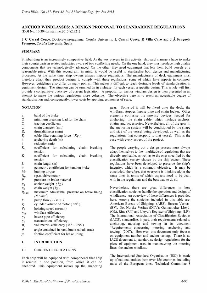
ANCHOR WINDLASSES: A DESIGN PROPOSAL TO STANDARDISE REGULATIONS (DOI No: 10.3940/rina.ijme.2015.a2.321) J C Carral Couce, Doctorate programme, Coruña University, L Carral Couce, R Villa Caro and J Á Fraguela Formoso, Coruña University, Spain SUMMARY Shipbuilding is an increasingly competitive field. As the key players in this activity, shipyard managers have to make their counterparts in related industries aware of two conflicting needs. On the one hand, they must produce high quality components that are technologically advanced. On the other, they need equipment that lets them build vessels at a reasonable price. With this second aim in mind, it would be useful to standardise both design and manufacturing processes. At the same time, ship owners always impose regulations. The manufacturers of deck equipment must therefore adapt their product designs to comply with these regulations, some of which have aspects in common. However, guidelines also differ on many points. This makes it difficult to reach desirable levels of standardisation in equipment design. The situation can be summed up in a phrase: for each vessel, a specific design. This article will first provide a comparative overview of current legislation. A proposal for anchor windlass design is then presented in an attempt to make the various regulations more cohesive. The objective here is to reach an acceptable degree of standardisation and, consequently, lower costs by applying economies of scale. NOTATION a band of the brake Q minimum breaking load for the chain C traction coefficient dc chain diameter (mm) Dt drum diameter (mm) cable-lifter retaining force ( Kg )
h anchoring depth (m) i reduction ratio K1, coefficient for calculating chain breaking
tension K2 coefficient for calculating chain breaking
tension L chain length (m) m geometric coefficient for band on brake Mf braking torque
r.p.m. drive motor P pressure on brake material
anchor weight ( kg ) chain weight ( kg )
. maximum admissible pressure on brake lining (N / mm2 )
F pump flow ( l / min. ) cylinder volume of motor ( cm3 )
Vs hoisting speed (m/min) windlass efficiency hawse pipe efficiency transmission efficiency
volumetric efficiency ( 0.8 – 0.95 ) angle contained in band brake radials (rad) friction coefficient for brake lining 1. INTRODUCTION 1.1 CURRENT REGULATIONS Each ship will be equipped with components that help it remain in one position, from which it can be anchored. This equipment makes up the anchoring
gear. Some of it will be fixed onto the deck: the windlass, stopper, hawse pipe and chain locker. Other elements comprise the moving devices needed for anchoring: the chain cable, which include anchors, chains and accessories. Nevertheless, all of the gear in the anchoring system will be conditioned by the shape and size of the vessel being developed, as well as the regulations that correspond to that vessel. This is the case with every aspect of the project. The people carrying out a design process must always adapt themselves to the multitude of regulations that are directly applicable, as well as to the ones specified by the classification society chosen by the ship owner. These regulations have been developed to preserve the ship’s integrity, which is a common objective. It may be concluded, therefore, that everyone is thinking along the same lines in terms of which aspects need to be dealt with in the regulations and the best way to do so. Nevertheless, there are great differences in how classification societies handle the operation and design of windlasses. An overview of these differences is provided here. Among the societies included in this table are: American Bureau of Shipping- (ABS), Bureau Veritas- (BV), Det Norske Veritas-(DNV), Germanicher Lloyd- (GL), Rina (RN) and Lloyd´s Register of Shipping- (LR). The International Association of Classification Societies (IACS), standardise, in part, their requirements related to anchoring, mooring and towing in its document “Requirements concerning mooring, anchoring and towing” (2007). However, this document only focuses on equipment number and anchor testing. There is no IACS document to standardise design regulations for the piece of equipment used in manoeuvring the mooring lines: the anchor windlass. The International Standard Organisation (ISO) is made up of national entities from over 156 countries, including most of the European ones. Technical Committee 8

Trans RINA, Vol 157, Part A2, Intl J Maritime Eng, Apr-Jun 2015
A-96 ©2015: The Royal Institution of Naval Architects
(TC8) deals with ship and marine technology. This committee has developed standards related to the equipment being examined here. Carral et al [1] looks at a situation that is similar to the one discussed here. In this case, the study is about the design of a towing winch and examines the third largest bibliographic source for naval architecture, the one provided by the International Maritime Organisation (IMO). In contrast, the IMO has no regulations on anchoring. There is a wide range of regulations and they have marked differences. Consequently, the project manager of a team is conditioned by the vessel’s classification society at the moment of carrying out the design process. This circumstance is a far cry from design and manufacture processes, in which recommended economies of scale are sought by standardising components. ISO Standards become the EN-ISO when they are accepted by the European Committee for Standardisation. By studying and comparing these standards, it is possible to establish a common core from which a common regulation can be developed for the future. Thus, there would be significant savings in equipment design and manufacturing costs. These reductions will affect three different areas: design, supplies and production. The first of these- design- will be affected because there is a greater number of common components and therefore fewer conceptual design drawings. Secondly, fewer suppliers are needed, especially when it comes to cast iron pieces. Economies of scale are involved with the third area of savings. A greater number of pieces is produced for each model. .As for assembling the equipment, the learning curve concept comes into play. Thanks to this, there are reductions of around 30% when four units of the same model are built. When all of these factors are taken into account, equipment costs may be decreased by over 25%. 2. COMPARING A SELECTION OF
RELEVANT REGULATIONS As mentioned earlier, this selection will include both classification society regulations and ISO standards. Simply looking at the former will be of great interest. In the case of tugs and their anchoring gear, Allan [2] has carefully examined the scope of each regulation. By doing so, it is possible to reach the conclusion that the regulations mainly cover operational aspects. Scant reference is made to the parameters of windlass design and manufacture [1]. The next section looks at how various regulations deal with calculating the operative parameters for the equipment related to traction and braking force.
For anchoring windlass design, both classification society and ISO propose using a concept of minimum breaking load for the chain (Q) as a variable on which the most relevant features of the equipment depend. Among these are traction and braking. This value will be obtained from the three tables included in the regulations for the three chain qualities normally considered (Q1, Q2, Q3), However, Lloyd´s Register (Eq 1) and Bureau Veritas (Eq 2) propose an alternative as they take into account the following formulae for this calculation: 44 0.08 (1) 9.807 44 0.08 10 (2)
The coefficient values are: Table 1 Coefficient K for calculating breaking force for the chain.
Grade
K1 (Lloyd´s Register of Shipping) K2
(Bureau Veritas) Chain
stopper No chain stopper
Q1 4.41 7.85 1
Q2 6.18 11.0 1.4
Q3 8.83 15.7 2 For calculating windlass traction, the traction coefficient C is employed. This is the value on which the classification societies and ISO coincide. It reflects the grade of chain to be used. To define the nominal traction for the windlass, coefficient C is multiplied by the square number for the chain diameter. The following table provides the coefficients given by the main classification societies and ISO standard 4568 [3].
(3) Table 2 Coefficient C to calculate the nominal traction for the windlass
Chain grade
DNVLloyd´s Register
Bureau Veritas
RINA Germanicher Loyd´s
ISO 4568
Q1
37.5 37.5 49.8 37.5 49.8 (*) 37.5Q2
42.5 42.5 56.5 42.5 56.5 (*) 42.5Q3
47.5 47.5 66.5 47.5 66.5 (*) 47.5* Germanicher Lloyd´s uses this as a formula for anchorage depth greater than 100 m.
0.218 100 (4) The braking force acts on the cable- lifter so that the gear does not slip. In the case of anchoring windlasses, the braking force specified in the regulations are defined as a

Trans RINA, Vol 157, Part A2, Intl J Maritime Eng, Apr-Jun 2015
©2015: The Royal Institution of Naval Architects A-97
percentage related to the chain’s breaking load (Q), as shown in Table 3. Table 3 - Braking force as a percentage of breaking load for the chain
* Calculating breaking load with Equation (1) ** Calculating breaking load with Equation (2) Until now, this study has focused on aspects related to how the windlass is operated. However, reference should also be made to other factors for design and manufacture. Here, the standard that comes into play is ISO 4568– 2006 -“SHIPBUILDING SEA – GOING VESSELS- WINDLASSES AND ANCHOR CAPSTANS” [3]. It is the one that places the greatest attention on windlass design parameters. Table 4 summarises classification society regulations and then compares these with content from ISO 4568. 3. PROPOSAL FOR STANDARDISATION
REGULATIONS AND WORKING HYPOTHESES
This proposal for achieving standardisation consists of adopting broad criteria based on the content in ISO 4568. The ISO standard has features that are in line with the classification societies related to traction and braking force. At the same time, the ISO has suitable design and manufacture specifications in terms of the cable- lifter, speed control, warping end and control devices, while the classification societies stand out for being silent on these matters (Table 4). Table 4 – Comparison between classification society regulations and ISO standards on anchoring windlass design
Classification soc. reg.
ISO 4568–2006
DESIGN AND MANUFACTURE
Cable- lifter
Indicates they must be declutchable/ no mention of geometry
Minimum of 5 points, in accordance with ISO 1704. Declutchable
Warping end Not mentioned Optional, to comply with ISO 6482
Strength requirements
With chain stopper: 0.45 x the chain’s breaking load; no
With chain stopper: 0.45 x the chain’s breaking load;
stopper: 0.80 x the breaking load
no stopper: refer to classification soc. standards
Control braking system
Some call for brake by electric windlass
With a brake capacity equivalent to 1.5 of nominal traction when electrically operated; 1.3 x when operated by other means
Emergency stop
Some require this Within reach of equipment
Protection
Some call for operational control (electric and hydraulic)
Must have torque limit switch
Control devices
Not mentioned Manual, returning to neutral position
Speed control Not mentioned Adjustable from zero to nominal speed
OPERATION
Nominal traction
Related to chain diameter and grade, but there are different procedures for calculating chain grade
Take into account: chain diameter value, chain grade and anchorage depth (under or over three shots)
Maximum traction
1.5 x nominal traction
1.5 x nominal traction
Nominal speed No less than 0.15 m/s.
No less than 0.15 m/s.
In the European Union (EU), more uniform standards help eliminate technical obstacles within the home market. They make it possible to evaluate product conformity through a system of accreditation, certification, testing and calibrations. Product development is also influenced by economic and technical reasons given that innovation must go hand and hand with this normalisation. For this reason, the European Committee for normalisation is increasingly merging ISO and EN –ISO standards in the field of ship construction, pleasure craft, equipment and machinery. Fulfilling standardised regulations is one step. Another involves accepting hypotheses based on rational assumptions. With these two steps it is possible to establish initial design conditions suitable for the chosen calculation process. In the absence of other conditions specified by the ship owner, initial ones will guide windlass design.
Force DNV / G.L / ISO/RINA
L.R.S. Bureau Veritas
ISO 4568
With chain stopper 45 %
45 % (*)
45% (**) 45 %
W/o chain stopper 80% 80% 80% 80%

Trans RINA, Vol 157, Part A2, Intl J Maritime Eng, Apr-Jun 2015
A-98 ©2015: The Royal Institution of Naval Architects
3.1 PROPOSAL FOR MORE COHESIVE REGULATIONS
The proposal for making windlass design more cohesive will include a set of minimum conditions the gear must fulfil so that the vast majority of existing standards are embraced. In this way, these standards could make up a proposal for standardising regulations: When the windlass is idle, the cable- lifter is
declutched and the brake is activated. The mechanical components of the windlass, including the foundations, must be capable of withstanding the pull applied on the pitch circle diameter of the cable- lifter equal to 45 % of the chain’s breaking load [3].
If the windlass is to be employed without the chain stopper, the static load must be equal to 80 % of the chain’s breaking load [3].
When the windlass is moving, and with the aim of considering the dynamic effects resulting from the anchoring manoeuvre, its mechanical components must be capable of withstanding a load perpendicular to the windlass’s axle. The application point of this load is to correspond with that of the pitch circle diameter of the cable- lifter cable-lifter. Its value is to be equal to the one corresponding to the following expression [3] :
71.25 (N) (5) The braking force will be such that, if the
windlass is going to work in conjunction with the stopper chain, with the cable- lifter declutchable from the motor, the brake must be capable of withstanding- without slipping- a static load of corresponding to 45 % of the chain’s breaking load, this being applied along the pitch circle diameter of the cable- lifter [3].
The brake holding load for a windlass without the chain stopper will be 80 % of the chain’s breaking load [3].
Should the brakes be activated manually, the levers must have a maximum scope of movement of 600 mm. If the brakes work by means of a hand wheel, this wheel must move in a clockwise motion [5].
With power brakes, the system must be designed in such a way that, if the equipment’s power supply fails, the brake will immediately and automatically start working [3].
The cable- lifter will have a coupling device that allows it to engage and disengage from the prime mover when it is not in use. Its shape and dimensions must respect ISO 1704 [6].
If there is a reduction gearbox, it must be lubricated on a regular basis and to a sufficient level if the equipment tilts up to 15 degrees [5].
Furthermore, it should also have a display panel for the oil level. Along those points in which grease lubrication is needed, there must be lubricating devices, such as grease nipples that are adjusted to ISO 7824 specifications. The gears must not be lubricated with grease.
If there are hydraulic windlasses, the system’s working pressure must not exceed 70% of the maximum permissible continuous pressures specified by the component’s manufacturer. When compared with all the other components of the system, it must have the lowest nominal pressure [4].
If the gearbox is reversible or it is a direct drive windlass, its system must ensure that the brakes on the motor are activated whenever the motor stops, intentionally or not. With the particular case of electrically operated windlasses, it is essential to use an electrical negative brake whose braking force is 1.5 times nominal traction [3]. For hydraulically operated windlasses, brake valves are used. They are to have a braking power that is 1.3 times normal traction.
Hoisting speed must be 9 m/min, which will be tested by raising the anchor and chain from 85 m. to 57.5 m. in depth [3]
If there is a warping end, ISO 6482 [7] will apply.
3.2 WORKING HYPOTHESES In order to design the windlass, it is essential to establish a range of initial conditions. These have to be carefully thought through and then incorporated into the set of standardised guidelines presented in point 3.1. When the windlass is in motion, its components
must be capable of withstanding a force that is, in minimum terms, over 25 % of the nominal force during its expected service life, as indicated by the manufacturer.[4]
If it is a dual anchor windlass, in addition to the forces mentioned earlier, it must be capable of withstanding 50 % of the total of each one of the forces applied on the cable- lifters [4]
The windlass motor must be able to operate for at least 30 minutes at the power that corresponds with the following value, calculated for the value pc corresponding to four shots of the chain:
8.7 Vs
60 6
If there are no data about how much the chain and
anchor weigh, the windlass motor has to be capable of operating for 30 minutes at the following power [4]. Please note that the expression does not comply

Trans RINA, Vol 157, Part A2, Intl J Maritime Eng, Apr-Jun 2015
©2015: The Royal Institution of Naval Architects A-99
with GL and BV requirements, in which case, the coefficient will be 66.5.
47.5 Vs
60 7
The windlass motor must be able to operate for at
least two minutes, at a power that exceeds 50 % of the one calculated in the section above [3].
The windlass motor and its operating and control systems must be prepared to withstand being started up six times in 30 minutes with a resting period of 1 hour [4].
The average hoisting speed will not fall below 9 m/min., nor go above 12 m/min. while there is nominal rotation and the motor is working at full load [3,4].
Calculations for ball bearings will comply with ISO 281, at a 90% reliability level and with an effective service life of 10 years. Lubricating options include grease, an oil bath or splash lubrication. If grease chambers are chosen, these will then have, through easy access, grease nipples that comply with ISO 7824.
Bearings are calculated at a reliability level of 90 %. Their effective service life must be five years under nominal loads and speeds [8].
The axle, clutch, cable- lifter and gearbox calculations are to have a 99% reliability level. Their fatigue during their service life will be along the same lines as the one for the windlass, and under a nominal workload [20].
To ensure that the lines and ropes last longer, if the windlass has warp ends, their diameter will be six times that of the rope and 16 times that of the line [10].
If it is electrically operated, it is advisable to have a squirrel cage, three-phase asynchronous motor. It must have, as a minimum, F class insulation and B class heating. The degree of protection should be (UNE 20324 – CEI 144) [11] or [12] IP-560 above deck and IP-540 in other cases [4].
4. DESIGN PROCESS FOR WINDLASS
BASED ON MORE COHESIVE REGULATIONS
The first step here entails calculating the equipment number using the values tabulated by the International Association of Classification Societies (IACS) [13].
These values are related to diameter, total length of the chain cable and anchor mass. They help determine the anchoring gear that the windlass must manoeuvre. By considering the standardised regulations and working hypotheses, it is possible to determine the main characteristics of the windlass in accordance with the data provided by the client. On the whole, the minimum data needed are:
- Windlass type and operation. - Number of anchoring lines. - Chain diameter and grade. Additional data are needed to complete basic information: hoisting speed, whether there are auxiliary warping ends and how the windlass is operated. To define an anchoring windlass, these parameters must be considered [4]: - Windlass type (single or symmetrical double
cable- lifter, combined or not mooring device). - Operational and technical features of the
gearbox in terms of reduction ratio. - Average and instantaneous power of the
windlass motor. - Geometry and dimensions of cable- lifter. - Warping end dimensions. - Brake type and dimensions. 4.1 WINDLASS TYPES Windlasses can be classified into two groups: dual anchor devices with two anchoring lines and single anchor ones, with only one anchoring line. At the same time, the latter group can be sub-classified as either horizontal or vertical according to their position in relation to the transmission axle of the cable- lifter. In general dual-anchor windlasses (Figure 1) are used with small chains, whose diameters are between 22 and 30 mm. With very small chains, whose diameters are below 20.5 mm, and those whose diameters exceed 30 mm, single-anchor windlasses are used [9]. (Figures 2 and 3).
Rear view
Frontal view Figure 1 – Double anchor windlass for a 26 mm chain

Trans RINA, Vol 157, Part A2, Intl J Maritime Eng, Apr-Jun 2015
A-100 ©2015: The Royal Institution of Naval Architects
Frontal view
Rear view Figure 2 – Single anchor windlass for a 40 mm chain and mooring reel
Frontal view
Rear view Figure 3 – Single anchor windlass for 58 mm chain and split mooring reel 4.2 OPERATING SYSTEM; TRANSMISSION
RATIO In terms of the way they operate, the most common systems are electric and hydraulic. Among electric motors, the asynchronous ones with alternate current stand out. The hydraulically-operated ones mostly use
rapid axial pistons motors connected to variable flow pumps. Radial piston motors are suitable for higher powered equipment [14], as the reducer gear is smaller. However, they have the drawback of being expensive and difficult to maintain. Both systems have one point in their favour: they make it possible to vary the hoisting speed. Moreover, they offer a constant torque, which is independent of the speed. On the other hand, small windlasses, with chains up to 30 mm, use asynchronous motors that have softstarters. For chains between 30 and 70 mm, there is a preference for hydraulic systems with axial pistons or electric systems with frequency converters. When chains are over 70 mm, hydraulic systems predominate; these have radial pistons. In general, windlasses have a mechanical reducer gear and it is necessary to determine their transmission ratio. When the transmission ratio for a reducer is the quotient between the number of times the input shaft, near the operating motor, rotates and the number of times the output shaft, near the cable- lifter, turns, the following expression works for the calculation [15]:
4. 10 8
With electrically operated devices, the motor speed corresponds with the one that is under full load, 1500 rpm. In the case of windlasses with auxiliary warping ends for mooring manoeuvres, if the required speed is around 30 m/min [10], frequency converters are particularly interesting. If a hydraulic system is chosen, the motor speed will depend on cylinder volume, as well as the flow supplied by the pump that feeds it, that is [16]:
1000
9
4.3 AVERAGE AND INSTANTANEOUS
POWER OF THE WINDLASS The windlass motor’s average power will depend on its number of cable- lifters, the size and grade of its chain, its hoisting speed, the mechanical efficiency of the motor and the geometry of the Hawser pipe. If the data known about the anchoring line include its cable diameter, the following formula can be applied to obtain the average power [4]:
63.760
10
The hoisting speed being V , values between 9 and 11 m/min. will be taken. Therefore, the value for K will be 0.91 for single cable- lifter windlasses and 1 for double

Trans RINA, Vol 157, Part A2, Intl J Maritime Eng, Apr-Jun 2015
©2015: The Royal Institution of Naval Architects A-101
cable- lifter models, while the windlass efficiency will range between 0.5 – 0.7 [4]. If data are available for chain grade and length, anchor weight, the performance of the hawse pipe (0.5 – 0.7) as well the reducer gear, it will be better to use the following formula [4]:
85.3 0.0260
11
Windlass efficiency is generally not known, but it is possible to obtain approximate this value by multiplying the unitary performance for each movement of its gears and for the cable- lifter. As a guide, these typical performance rates may be cited t [4]: - A pair of cylindrical gears with a transmission
ratio i 8: = 0.98 – 0.95 - A pair of conical gears with a transmission ratio
i 10: = 0.95 – 0.90 - An arrangement of reversible worm gears with
endless screws = 0.5 – 0.7 - An arrangement of irreversible worm gears with
endless screws = 0.4 – 0.5 - Warp end performance may be given as 0.95 To hoist the anchor from the sea bed, the motor has to surpass the anchor’s holding power. Thus, for two minutes the motor should be run at instantaneous power, which is calculated below [4]:
20.6 0.2
6.12 12
4.4 GEOMETRY AND DIMENSIONS FOR THE
CABLE- LIFTER ON THE WARPING END Cable- lifters are defined by the diameter of the chain to which they are geared. Another factor is the number of points in their geometry. Their shape must allow them to be in contact with at least two snugs along the chain. This position is determined by the angle at which the cable- lifter hugs the chain. Its angle value will be, at the same time, determined by the relative position between the Hawse pipe on deck or the chain stopper and the spurling pipe through which the chain passes to the case. For the chain to wind correctly in the cable- lifter, it is necessary to test it once the gear is placed on its pole on board. ISO 21-1985 [16] specifies the shape taken by a cable- lifter with a diameter of 44 mm, with the opportunity of having five, six or seven snugs. Figure 4 shows its shape and defining parameters. For chains over the diameter mentioned above, ASTM F- 765 – 93 is applied [18]. It is important to calculate the pitch circle diameter of the cable-lifter, which is achieved with this formula [4]:
1.27 10 (13)
Figure 4 – Five-snug cable- lifter with its main parameters – ISO 21 Furthermore, the cable- lifter is freely mounted on the windlass axle. It receives its drive torque through the dog clutch. Given its high radial load and low speed, it is normally mounted over bronze bearings. Ball bearings are only used when the equipment has a chain that is less than 24 mm Warping ends in anchoring windlasses are used to turn the mooring lines near where the forecastle deck is located. They share an axle with the windlass. To obtain a suitable hoisting speed, they should rotate twice as many times as the cable-lifter. The simplest way to achieve this is to vary the motor’s drive speed. Another option, for winches with chains over 70 mm, is to run them at an intermediate reduction. Their Z shape lets them fit neatly on deck. The warping end diameter must be of a size that stops the line or rope from deteriorating as it is handled by the equipment. Thus, the minimum diameter of the warping end must be over six times that of the rope [10, 15]. 4.5 BRAKE TYPE AND DIMENSIONS Every cable- lifter must have a brake that allows it to reduce its speed or stop whenever the chain is wound out. Moreover, the brake will hold back the equipment during anchoring. In most cases, a band brake is involved. It is differential because it is self-energising and can even be automatic. (Figure 5) To obtain the necessary force from the band on top of the brake drum, windlasses include systems that multiply the force made on the lever or hand wheel. (Figure 5)

Trans RINA, Vol 157, Part A2, Intl J Maritime Eng, Apr-Jun 2015
A-102 ©2015: The Royal Institution of Naval Architects
T2
T1
Mt
Figure 5 Band brake at a fixed point and in differential mode Brake calculations must ensure that they can withstand the maximum static load, as specified by the ISO. It is also important to check that the maximum pressure over the brake linings falls within admissible levels. Braking torque goes hand in hand with the braking force acting on the mooring drum attached to the cable- lifter, as demonstrated below [19]:
14
When the drum brake diameter is linked to the diameter of the cable- lifter on which it rests, coefficient “i“ will be the transmission ratio for the differential brake. This coefficient will correspond to the multiplication of the force applied to the lever or hand wheel, whose mechanical efficiency will be . The windlass is normally alongside the chain stopper. In this case, the cable- lifter’s retaining force Fr can be found in the value for 45% of the chain’s breaking load [3]. This is in agreement with the expression in Table 3.
0.45 (15) The width for the band of the brake with the same name is obtained with the following expression [19]:
1
2 16
Where m is the geometric coefficient of the band interacting with the angle found within the band brake (), the friction coefficient for the brake lining is (). The value Pmax , maximum point pressure admissible for the brake lining’s material, will depend on the material used. Moreover, for the brake geometry, the average pressure over the brake must be lower than the average admissible pressure on the material of choice.
5. CONCLUSIONS When opting for an anchoring windlass design, classification society specifications and ISO standards must be taken into account. The IMO, in contrast, has no regulations on this subject. There is a great deal of common ground between what has been produced by the classification societies and ISO 4568: the sum total of working specifications related to traction, speed and braking force. However, the classifications societies are noticeably reticent over aspects of design and manufacture, such as the geometry and dimensions of the warping ends, cable- lifter, operating systems and control devices. Using ISO standards as a base, it is possible to produce regulations that are cohesive, and, at the same time, guarantee that the main bulk of classification society standards are met. In this way, it is also possible to establish design and manufacture specifications that make it easier to standardise components. Along with established codes, there are solid working hypotheses. With all of these, a design can be proposed that determines the main characteristics of the windlass in accordance with the data provided by the client. With this solid base, procedures have been put forward for determining windlass type (single or double l anchor), as well as operating modes. One can also define the gear box through the reduction ratio, the average and instantaneous power for the windlass motor, cable- lifter geometry and dimensions, warping end dimensions and, finally, brake type and dimensions. 6. REFERENCES 1. CARRAL COUCE J, CARRAL COUCE L,
FRAGUELA FORMOSO J, FERNÁNDEZ SOTO J. El chigre de remolque en las maniobras de altura y de escolta: propuesta de armonización en sus parámetros de diseño. DYNA – Industria y Energía 2013; 88: 395 - 399. DOI 10.6036/5657, ISSN: 0012-7361.
2. ALLAN, ROBERT G., A proposal for harmonized international regulations for the design and construction of tugboats. In: Ter Haar J (ed) Towing Manual- Offshore an ocean towage with related shipping matters and opinions. Rotterdam: STC Group, 2010, pp 146-162 , ISBN 978 – 90 – 810900-2-5.
3. ISO 4568:1986. Shipbuilding sea going vessels- windlasses and anchor capstans.
4. CARRAL COUCE L, CARRAL COUCE J. Normas prácticas para el diseño de molinetes de anclas, Revista de Ingeniería Naval 1999; 761, 698- 702.
5. ISO 7825. Deck machinery – general requirements.
Trans RINA, Vol 157, Part A2, Intl J Maritime Eng, Apr-Jun 2015
©2015: The Royal Institution of Naval Architects A-103
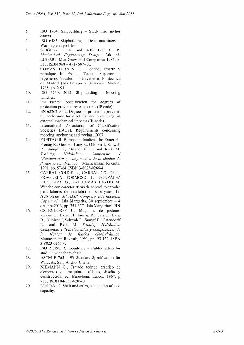
6. ISO 1704. Shipbuilding – Stud- link anchor chains.
7. ISO 6482. Shipbuilding – Deck machinery – Warping end profiles.
8. SHIGLEY J. E. and MISCHKE C. R. Mechanical Engineering Design. 3th ed. LUGAR: Mac Graw Hill Companies 1985, p. 528, ISBN 968 – 451- 607– X.
9. COMAS TURNES E. Fondeo, amarre y remolque. In: Escuela Técnica Superior de Ingenieros Navales – Universidad Politécnica de Madrid (ed) Equipo y Servicios. Madrid, 1985, pp. 2-91.
10. ISO 3730: 2012. Shipbuilding – Mooring winches.
11. EN 60529. Specification for degrees of protection provided by enclosures (IP code).
12. EN 62262:2002. Degrees of protection provided by enclosures for electrical equipment against external mechanical impacts (IK code).
13. International Association of Classification Societies (IACS). Requirements concerning mooring, anchoring and towing , 2007.
14. FREITAG R. Bombas hidráulicas, In: Exner H., Freitag R., Geis H., Lang R., Ollolzer J, Schwab P., Sumpf E., Ostendorff U. and Reik M. Training Hidráulico. Compendio I "Fundamentos y componentes de la técnica de fluidos oleohidráulica. Mannesmann Rexroth, 1991, pp. 57-64, ISBN 3-8023-0266-4.
15. CARRAL COUCE L., CARRAL COUCE J., FRAGUELA FORMOSO J., GONZÁLEZ FILGUEIRA G., and LAMAS PARDO M. Winche con caracteristicas de control avanzadas para labores de maniobra en superyates. In: IPIN Actas del XXIII Congreso Internacional Copinaval , Isla Margarita, 30 septiembre – 4 octubre 2013, pp. 351-377 . Isla Margarita: IPIN
16. OSTENDORFF U. Maquinas de pistones axiales. In: Exner H., Freitag R., Geis H., Lang R., Ollolzer J, Schwab P., Sumpf E., Ostendorff U. and Reik M. Training Hidráulico. Compendio I "Fundamentos y componentes de la técnica de fluidos oleohidráulica. Mannesmann Rexroth, 1991, pp. 93-122, ISBN 3-8023-0266-4.
17. ISO 21:1985 Shipbuilding – Cable- lifters for stud – link anchors chain
18. ASTM F 765 – 93 Standars Specification for Wildcats, Ship Anchor Chain.
19. NIEMANN G., Tratado teórico práctico de elementos de máquinas: cálculo, diseño y construcción, ed. Barcelona: Labor., 1967, p 728, ISBN 84-335-6287-8.
20. DIN 743 - 2. Shaft and axles, calculation of load capacity.

Trans RINA, Vol 157, Part A2, Intl J Maritime Eng, Apr-Jun 2015
A-104 ©2015: The Royal Institution of Naval Architects
APÉNDICE 1
Figure 6 Windlass flow design diagram based on standardised regulations
CALCULATE:
EQUIPMENT NUMBER‐IACS (13)
‐ DIAMETER GRADE AND TOTAL LENGTH OF CHAIN CABLE
‐ ANCHOR MASS
DEFINE:
WINDLASS TYPE:
‐ DUAL OR SINGLE ANCHOR
‐ HORIZONTAL OR VERTICAL
TRANSMISSION RATIO: OPERATING SYSTEM
‐ ELECTRIC OR HIDRAULIC OPERATION
‐ OBTAIN TRANSMISSION RATIO (8)
AVERAGE AND INSTANTANEOUS POWER:
AVERAGE POWER:
‐ OBTAIN MECHANICAL EFFICIENCY (REF.4)
‐WITH ANCHORING LINE DATAS, USE (10)
‐WITH CHAIN GRADE, LENGHT AND ANCHOR MASS DATAS, USE (11)
INSTANTANEOUS POWER:
‐ USE (12)
GEOMETRY AND DIMENSIONS FOR THE CABLE LIFTER AND WARPING END:
‐ CABLE LIFTERS ARE DEFINED BY: ISO 21 1985 AND ASTM F‐765‐93
‐WARPING END DIMENSIONS BY REF. 10 AND 15
BRAKE DIMENSIONS:
‐ OBTAIN RETAING FORCE (15) AND WIDTH FOR THE BAND (16)

Diseño de maquinaria de cubierta de buques, en base a una propuesta razonada de armonización reglamentaria Pág. 47
5.2. STANDARDISING THE DESIGN AND
PRODUCTION OF MOORING WINCHES
THROUGH MORE COHESIVE REGULATIONS: A
NECESSARY STEP Juan Carlos Carral Couce, Luis Carral Couce, José Ángel Fraguela Formoso, Raúl Villa Caro
Transactions RINA, Vol. 157, Part A4, International Journal Maritime Engineering Oct-Dec 2015 (DOI. No: 10.3940/rina.ijme.2015.a4.342

Diseño de maquinaria de cubierta de buques, en base a una propuesta razonada de armonización reglamentaria Pág. 48
Trans RINA, Vol 157, Part A4, Intl J Maritime Eng, Oct-Dec 2015
©2015: The Royal Institution of Naval Architects A-251
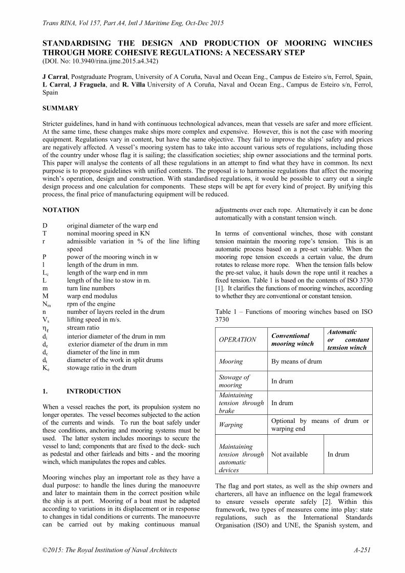
STANDARDISING THE DESIGN AND PRODUCTION OF MOORING WINCHES THROUGH MORE COHESIVE REGULATIONS: A NECESSARY STEP (DOI. No: 10.3940/rina.ijme.2015.a4.342) J Carral, Postgraduate Program, University of A Coruña, Naval and Ocean Eng., Campus de Esteiro s/n, Ferrol, Spain, L Carral, J Fraguela, and R. Villa University of A Coruña, Naval and Ocean Eng., Campus de Esteiro s/n, Ferrol, Spain SUMMARY Stricter guidelines, hand in hand with continuous technological advances, mean that vessels are safer and more efficient. At the same time, these changes make ships more complex and expensive. However, this is not the case with mooring equipment. Regulations vary in content, but have the same objective. They fail to improve the ships’ safety and prices are negatively affected. A vessel’s mooring system has to take into account various sets of regulations, including those of the country under whose flag it is sailing; the classification societies; ship owner associations and the terminal ports. This paper will analyse the contents of all these regulations in an attempt to find what they have in common. Its next purpose is to propose guidelines with unified contents. The proposal is to harmonise regulations that affect the mooring winch’s operation, design and construction. With standardised regulations, it would be possible to carry out a single design process and one calculation for components. These steps will be apt for every kind of project. By unifying this process, the final price of manufacturing equipment will be reduced. NOTATION D original diameter of the warp end T nominal mooring speed in KN r admissible variation in % of the line lifting
speed P power of the mooring winch in w l length of the drum in mm. Lc length of the warp end in mm L length of the line to stow in m. m turn line numbers M warp end modulus Nm rpm of the engine n number of layers reeled in the drum Vs lifting speed in m/s. stream ratio di interior diameter of the drum in mm de exterior diameter of the drum in mm dc diameter of the line in mm dt diameter of the work in split drums Ke stowage ratio in the drum
1. INTRODUCTION When a vessel reaches the port, its propulsion system no longer operates. The vessel becomes subjected to the action of the currents and winds. To run the boat safely under these conditions, anchoring and mooring systems must be used. The latter system includes moorings to secure the vessel to land; components that are fixed to the deck- such as pedestal and other fairleads and bitts - and the mooring winch, which manipulates the ropes and cables. Mooring winches play an important role as they have a dual purpose: to handle the lines during the manoeuvre and later to maintain them in the correct position while the ship is at port. Mooring of a boat must be adapted according to variations in its displacement or in response to changes in tidal conditions or currents. The manoeuvre can be carried out by making continuous manual
adjustments over each rope. Alternatively it can be done automatically with a constant tension winch. In terms of conventional winches, those with constant tension maintain the mooring rope’s tension. This is an automatic process based on a pre-set variable. When the mooring rope tension exceeds a certain value, the drum rotates to release more rope. When the tension falls below the pre-set value, it hauls down the rope until it reaches a fixed tension. Table 1 is based on the contents of ISO 3730 [1]. It clarifies the functions of mooring winches, according to whether they are conventional or constant tension. Table 1 – Functions of mooring winches based on ISO 3730
OPERATION Conventional mooring winch
Automatic or constant tension winch
Mooring By means of drum
Stowage of mooring
In drum
Maintaining tension through brake
In drum
Warping Optional by means of drum or warping end
Maintaining tension through automatic devices
Not available In drum
The flag and port states, as well as the ship owners and charterers, all have an influence on the legal framework to ensure vessels operate safely [2]. Within this framework, two types of measures come into play: state regulations, such as the International Standards Organisation (ISO) and UNE, the Spanish system, and
Trans RINA, Vol 157, Part A4, Intl J Maritime Eng, Oct-Dec 2015
A-252 ©2015: The Royal Institution of Naval Architects
international conventions from the International Maritime Organisation (IMO) and International Labour Organisations (ILO). On the other hand, owners and charterers have to juggle varying sets of regulations. Regulatory bodies in this sector include the Oil Companies International Marine Forum (OCIMF) and International Gas Tanker and Terminal Operators (SIGTTO). Another entity is the classification society chosen by the ship owner. Here, the regulations on winches from all these sources have been studied. 156 countries send representatives from their own standard-setting bodies to the ISO. Among these countries are most of the European states. Their practical guidelines have been developed with reference to the ISO – TC 8 Technical Committee on Shipbuilding and Marine Structure). ISO 3730 “Shipbuilding – Mooring Winches” [1] refers to designing and testing mooring winches, including their components. These documents inform this study. Another document is provided by the Oil Companies International Marine Forum, whose mission is to promote maritime safety through by using tankers and terminals in a controlled way. To this end, a range of associations from this sector have formed a working group [3]. This group produced “Mooring Equipment Guidelines – MEG3”, which establishes the basic principles of safe mooring [3]. Thanks to an increase in demand, shipping has evolved over the XX Century to take its place among the vanguard in the field of logistics. Economies of scale have been applied and ship registration has been liberalised. At the same time, transport systems- particularly those for ships and ports- have made strides as costs are continuously being reduced. That is why this sector enjoys a privileged position. [4]. As it continues being improved in the name of competitiveness, the shipping of the future will still need to have its operating costs reduced. This trend means that both ship building and running costs will continue to be lowered. If the implementing regulations are standardised, the design and manufacture of mooring equipment will be standardised. The cost of building and operating vessels will be reduced in keeping with the needs of shipping. 2. COMPARING EXISTING REGULATIONS Before one can compare the regulations, it is necessary to establish a series of definitions so that this comparison is homogeneous, as shown in Appendix 1. Classification societies have sought to harmonise regulations through the International Association of Classification Societies (IACS) [5]. “Requirements concerning mooring, anchoring and towing-UAR2” establish conditions that the mooring lines (ropes and cables) must meet when the area below the waterline is subjected to a 2.5 m/s current and the one above it is subjected to winds of 25 m/s. However, their angles of incidence are not specified. In these regulations, the
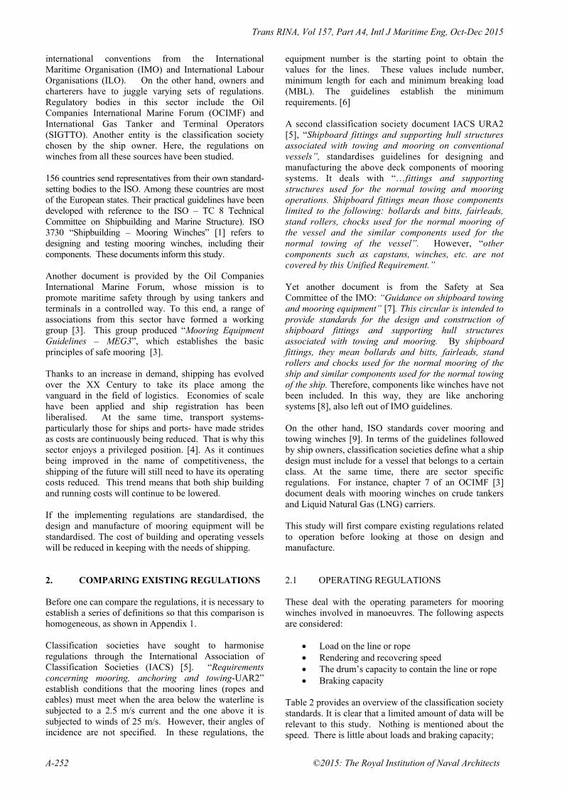
equipment number is the starting point to obtain the values for the lines. These values include number, minimum length for each and minimum breaking load (MBL). The guidelines establish the minimum requirements. [6] A second classification society document IACS URA2 [5], “Shipboard fittings and supporting hull structures associated with towing and mooring on conventional vessels”, standardises guidelines for designing and manufacturing the above deck components of mooring systems. It deals with “…fittings and supporting structures used for the normal towing and mooring operations. Shipboard fittings mean those components limited to the following: bollards and bitts, fairleads, stand rollers, chocks used for the normal mooring of the vessel and the similar components used for the normal towing of the vessel”. However, “other components such as capstans, winches, etc. are not covered by this Unified Requirement.” Yet another document is from the Safety at Sea Committee of the IMO: “Guidance on shipboard towing and mooring equipment” [7]. This circular is intended to provide standards for the design and construction of shipboard fittings and supporting hull structures associated with towing and mooring. By shipboard fittings, they mean bollards and bitts, fairleads, stand rollers and chocks used for the normal mooring of the ship and similar components used for the normal towing of the ship. Therefore, components like winches have not been included. In this way, they are like anchoring systems [8], also left out of IMO guidelines. On the other hand, ISO standards cover mooring and towing winches [9]. In terms of the guidelines followed by ship owners, classification societies define what a ship design must include for a vessel that belongs to a certain class. At the same time, there are sector specific regulations. For instance, chapter 7 of an OCIMF [3] document deals with mooring winches on crude tankers and Liquid Natural Gas (LNG) carriers. This study will first compare existing regulations related to operation before looking at those on design and manufacture. 2.1 OPERATING REGULATIONS These deal with the operating parameters for mooring winches involved in manoeuvres. The following aspects are considered:
Load on the line or rope Rendering and recovering speed The drum’s capacity to contain the line or rope Braking capacity
Table 2 provides an overview of the classification society standards. It is clear that a limited amount of data will be relevant to this study. Nothing is mentioned about the speed. There is little about loads and braking capacity;

Trans RINA, Vol 157, Part A4, Intl J Maritime Eng, Oct-Dec 2015
©2015: The Royal Institution of Naval Architects A-253
Table 2 – Comparison of classification society standards
Det Norske Veritas
Lloyd´s Register of Shipping
Bureau Veritas Germanischer Lloyd
American Bureau of Shipping
LOAD
Nominal load between 22% and 33 % of the mooring rope’s maximum breaking load (MBL)
Only specifies that the lower value is 15 tn-f
Not included
Only specifies that the lower value is 15 tn-f
Not included
SPEED Not included
BRAKING CAPACITY
0.8 of the MBL of the mooring rope
Not included
DRUM CAPACITY
Determines minimum length for each rope
Determines minimum length for each line and storage value: containing 150 m. of rope with 80 mm. diameter.
Determines minimum length for each line.
only the Det Norske Veritas (DNV) sets an interval load value. The Lloyd’s Register of Shipping and DNV establish braking capacity. For the drum’s capacity, Germanischer Lloyd (GL) provides a minimum value based on a diameter and length to be contained. In contrast ISO 3730 [1] includes the definitions mentioned above. It also has a table with the values relating to operating parameters for ropes whose diameters range between 18 and 48 mm. 2.2 DESIGN AND MANUFACTURING
REGULATIONS. Classification societies simply pay no attention to design and construction standards for mooring winches. For this analysis to be complete, data from ISO 3730 [1] and the OCIMF’s MEG 3 (3) should be considered. Table 3 gives a clear overview of the existing regulations. Regulations must be standardised. In this way, equipment manufacturers can optimise their work by standardising designs and production methods. In turn, this would lead to economies of scale [8]. Classification societies focus on how the winches operate and forget about design and production. ISO standards and OCIMF documents deal with both operational and design factors. The two documents coincide; it is clear that the ISO guidelines have inspired the OCIMF regulations.
3. PROPOSAL FOR HARMONISING REGULATIONS
This proposal consists of adopting new criteria for which ISO 3730 – 2112 serves as a linchpin. In the few aspects they cover- load and braking forces- the classification societies coincide with ISO guidelines. However, the ISO deals with other working aspects, such as speeds and drum capacity. Moreover, these standards cover the design and manufacture of drums and warp ends, as well as speed control and display panels. The fact that classification societies do not mention these stands out (Table 3). Thus, the ISO standards are in a better position to inform a proposal to standardise regulations. 3.1 PROPOSAL TO HARMONISE
REGULATION EXIGENCIES An in-depth study of the contents of [1] [10] points the way towards these guidelines:
The value adopted for the nominal load of the mooring winch should be 33% of the rope’s MBL [1] [3].
The maximum load must not exceed 80% of the rope’s MBL [1].
With constant tension winches, the following values are to be adopted to establish the rendering and recovery loads [1] :

Trans RINA, Vol 157, Part A4, Intl J Maritime Eng, Oct-Dec 2015
A-254 ©2015: The Royal Institution of Naval Architects
Rendering loads - 0.5 times the rope’s MBL.
Recovery loads - 0.5 times the equipment’s nominal load.
The equipment’s dry running speed is to be 0.5 m/s (30 m/min.) [1].
As for the drum’s speed under nominal loads, this will vary according to the diameter of the line or rope. The following table provides the values to be adopted [1] (Table 4).
As the creep speed, the recommended value is 0.5 times the nominal speed. Variations are in accordance with Table 5 [1] .
Braking capacity is to be 0.8 times the rope’s MBL [1].
To avoid damaging the cable, the interior diameter of the drum is to be at least 16 times the line’s diameter and six times that of the rope [1].
For the drum design, the type of line to be used is 6 x 36 or 6x41 steel- cored Warrington Seale, in accordance with ISO 2408 [11]. A possible alternative, however, is to use mooring lines whose fibres comply with EN-ISO-1141 (2012) - Fibre ropes [12] [1].
Drum capacity to hold the rope is to adopt a double configuration: minimum and maximum. These values are to follow the guidelines in Table 6 [1] .
With the drum’s exterior diameter, it should be possible to have between five and eight layers in the spool. This means that the exterior diameter is to have a value of (see Table 7)[1] .
The drum has to be long enough to hold all of the rope indicated. In the case of split drums that have a stowage and working spool, the former is to have no more than five layers. The working zone is to have only one layer; its length cannot exceed 10 times the rope’s diameter [1].
If the drum is declutchable, its braking system must have a holding capacity equal to 0.8 times the rope’s MBL [1].
All the prime movers of the winches must have an automatic braking system equivalent to 1.5 times the nominal load for electric and y 1.25 for hydraulic systems [1].
In the case of electric systems, the winch motor must be ready to carry out eight start-ups in an hour with intermediate two-minute periods of rest. For five minutes, it is to run at a power that exceeds 20 % of its nominal power [10].
If the system is hydraulic, the motor’s working pressure must be no more than 70 % of the maximum admissible continuous pressure. For five minutes, the system must be capable of running 15% above its nominal pressure [8].
In electric systems, the motors are to have thermal class F insulation and class B heat resistance. The level of protection will be UNE 20324 – CEI 144, IP-560 when above deck and IP-540 in other cases [13] [14].
3.2 WORKING HYPOTHESIS Using the exigencies of the regulations as a starting point, working hypotheses will be made:
When the winch is in operation, its mechanical components must be capable of withstanding, as a minimum, a load that exceeds 25 % of the nominal load throughout the service life established by the manufacturer [10] .
It is necessary to limit the difference in rope speed between the first and second working layer. When the motor is working at a constant speed, the ratio between the exterior (de) and interior diameters (di) of the drum, de /di, must fall between 1.5 and 3. When the motor has a variable speed, this may be between 2 and 5 [10].
Ball bearings are calculated in accordance with ISO 281. There is a 90% confidence level for a 10-year service life, if the bearings are lubricated [8]. Grease chambers are used with easy access nipples, following the guidelines in ISO 7825 [15].
Bearings are to be calculated with a 90 % confidence level and a service life of five years under nominal loading and speed conditions [16].
The axles, clutch and gearbox are to be calculated at a 99% confidence level reaching the point of fatigue. The service life will be equivalent to the service life of the winch, under normal working loads [17].
To ensure the long life of the cables and ropes, if the winch has warp ends, these must have a diameter that is at least six times that of the rope and 16 times that of the cable [3].
If the winch is in operation, its mechanical components must be capable of withstanding a load that is at least over 20 % the nominal load during the service life indicated by the manufacturer [10].
4. PROPOSAL FOR CALCULATING
COMPONENT DESIGN 4.1. INPUT DATA The data that are necessary for defining the winch are provided in reference [10]. These include:
Type of work that the winch will carry out. Traction or pull. Rope length it needs to stow.
Occasionally, additional data are provided to complement the basic information. Among these data are: motor type desired to be the prime mover, line diameter to be used, rendering and recovery speeds, braking capacity, drum size and type and, finally, type of gear box. The first step is to find out the nominal traction or pull. With this information, it is possible to obtain the value for the rope diameter and nominal speed, based on the
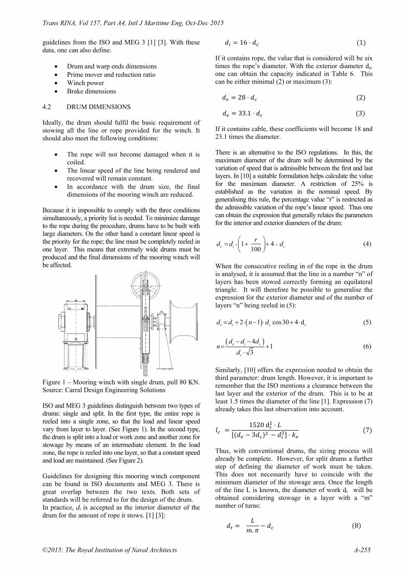
Trans RINA, Vol 157, Part A4, Intl J Maritime Eng, Oct-Dec 2015
©2015: The Royal Institution of Naval Architects A-255
guidelines from the ISO and MEG 3 [1] [3]. With these data, one can also define:
Drum and warp ends dimensions Prime mover and reduction ratio Winch power Brake dimensions
4.2 DRUM DIMENSIONS Ideally, the drum should fulfil the basic requirement of stowing all the line or rope provided for the winch. It should also meet the following conditions:
The rope will not become damaged when it is coiled.
The linear speed of the line being rendered and recovered will remain constant.
In accordance with the drum size, the final dimensions of the mooring winch are reduced.
Because it is impossible to comply with the three conditions simultaneously, a priority list is needed. To minimize damage to the rope during the procedure, drums have to be built with large diameters. On the other hand a constant linear speed is the priority for the rope; the line must be completely reeled in one layer. This means that extremely wide drums must be produced and the final dimensions of the mooring winch will be affected.
Figure 1 – Mooring winch with single drum, pull 80 KN. Source: Carral Design Engineering Solutions ISO and MEG 3 guidelines distinguish between two types of drums: single and split. In the first type, the entire rope is reeled into a single zone, so that the load and linear speed vary from layer to layer. (See Figure 1). In the second type, the drum is split into a load or work zone and another zone for stowage by means of an intermediate element. In the load zone, the rope is reeled into one layer, so that a constant speed and load are maintained. (See Figure 2). Guidelines for designing this mooring winch component can be found in ISO documents and MEG 3. There is great overlap between the two texts. Both sets of standards will be referred to for the design of the drum. In practice, di is accepted as the interior diameter of the drum for the amount of rope it stows. [1] [3]:
16 1 If it contains rope, the value that is considered will be six times the rope’s diameter. With the exterior diameter de, one can obtain the capacity indicated in Table 6. This can be either minimal (2) or maximum (3):
28 2
33.1 3 If it contains cable, these coefficients will become 18 and 23.1 times the diameter. There is an alternative to the ISO regulations. In this, the maximum diameter of the drum will be determined by the variation of speed that is admissible between the first and last layers. In [10] a suitable formulation helps calculate the value for the maximum diameter. A restriction of 25% is established as the variation in the nominal speed. By generalising this rule, the percentage value “r” is restricted as the admissible variation of the rope’s linear speed. Thus one can obtain the expression that generally relates the parameters for the interior and exterior diameters of the drum:
1 4100e i c
rd d d
(4)
When the consecutive reeling in of the rope in the drum is analysed, it is assumed that the line in a number “n” of layers has been stowed correctly forming an equilateral triangle. It will therefore be possible to generalise the expression for the exterior diameter and of the number of layers “n” being reeled in (5):
2 1 cos30 4 de i c cd d n d (5)
4
13
e i c
c
d d dn
d
(6)
Similarly, [10] offers the expression needed to obtain the third parameter: drum length. However, it is important to remember that the ISO mentions a clearance between the last layer and the exterior of the drum. This is to be at least 1.5 times the diameter of the line [1]. Expression (7) already takes this last observation into account.
1520d3 7
Thus, with conventional drums, the sizing process will already be complete. However, for split drums a further step of defining the diameter of work must be taken. This does not necessarily have to coincide with the minimum diameter of the stowage area. Once the length of the line L is known, the diameter of work dt will be obtained considering stowage in a layer with a “m” number of turns:
.
8

Trans RINA, Vol 157, Part A4, Intl J Maritime Eng, Oct-Dec 2015
A-256 ©2015: The Royal Institution of Naval Architects
Figure 2 – Mooring winch with a split drum, pull 100 KN Source: Carral Design Engineering Solutions For conventional spooling devices, the drum must be long enough to contain the entire rope within a number of layers that will range from five to eight. As indicated in [3] (pag. 140. 3 – MEG3) when dealing with elevated loads, it is convenient to limit the number of layers. If not, the line stowed in the lower layers may be bitten by the top ones due to the traction they exert. In these cases, the recommended stowage limit is four layers. With ropes subjected to a heightened load, a good option is to use drums of no more than five layers. In the work area, all the line is reeled into only one layer. This area is not to exceed 10 times the diameter of the High Modulus Polyethylene (HMPE) line or rope. If a mooring line is used, this amount can be reduced to six times its diameter. [1]. Table 8 summarises the drum geometry for constant tension mooring winches; it deals with the drum subject to load and the other one, a split drum. A final step is to measure the maximum load that the line undergoes in its first layer when it is reeled in [11]. This is obtained by considering the nominal load (T) as that which is produced in the layer corresponding to the average drum diameter:
2 9
4.3 WARP END DIMENSIONS AND SHAPE As is the case with the drums, the warp end diameters have to ensure that the mooring line will not be damaged when reeled in. The diameter of the rim groove will be the one obtained through the expression [2] [18].
6 10 In [18], to calculate the dimensions and profile of the warp ends, two models may be considered: one for the
normal length and another for its longer counterpart (type C and E). The process merely involves calculating the value for the warp end’s length end (L c) and the value for the parameter M known as modulus:
6 11
3 12
In Figure 3, the parameters for the warp end profile are shown; they coincide perfectly with what the regulation indicates [18].
Figure 3 – Profile of the normal and longer warp end according to ISO 6482 (notation used in the mentioned standard), Source: ISO 6482
Figure 4 –Longitudinal section of the mooring winch with a double split drum, Source: Carral Design Engineering Solutions.

Trans RINA, Vol 157, Part A4, Intl J Maritime Eng, Oct-Dec 2015
©2015: The Royal Institution of Naval Architects A-257
Table 3 – Comparison of the standards set by the classification societies, ISO 3730–2012 [1] and OCIMF/ MEG3 -2008 [3]
Classification societies
Norm ISO 3730–2012
OCIMF- MEG3
DESIGN AND CONSTRUCTION
Rope drum
Not mentioned
Defines: Capacity, interior and exterior diameter and length. In split drums, defines load zone.
Defines: Interior diameter and capacity. In split drums, defines load zone.
Warping end Not mentioned Optional, complying with ISO 6482
Not mentioned
Prime mover braking Not mentioned
-Electric: 1.5· nominal load. -Hydraulic: 1.25 nominal load.
Not mentioned
Spooling device Not mentioned Optional Not mentioned
Prime mover Not mentioned
Electric in accord. with IEC 92 and IEC 529, hydraulic, in accord. with ISO 4413
Not mentioned
Emergency stop Not mentioned Within easy reach of equipment
Not mentioned
Protection Not mentioned Torque limiter needed Not mentioned
Clutch Not mentioned Should be between prime mover and drum
Not mentioned
Control panel Not mentioned Manual, returning to neutral position
Not mentioned
OPERATION
Drum load
Does not distinguish between them; only the DNV determines interval for nominal load according to the rope’s MBL
0.33 rope’s MBL Between 0.22 and 0.33 times rope’s MBL
Holding force 0.8 rope’s MBL 0.5·rope
Recovery load 0.5 nominal load Not mentioned
Rendering load 0.5 rope’s MBL Not mentioned
Nominal speed
Not mentioned
According to nominal load
According to nominal load
Light line speed 0.5 m/s. 0.75m/s
Creep speed Inferior to 0.5·speed nominal and below 0.15 m/s.
Not mentioned
Drum brake capacity GL and DNV determines 0.8 rope’s MBL
Determine a value of 0.8 rope’s MBL
Determines a value of 0.8 rope’s MBL
Drum capacity
In general, not specific, except GL, which determines min. stowage capacity
Determine a min. and max. value for length in each diameter of rope
Determine a min. and max. value for length in each diameter of rope

Trans RINA, Vol 157, Part A4, Intl J Maritime Eng, Oct-Dec 2015
A-258 ©2015: The Royal Institution of Naval Architects
Table 4 –Nominal speed for distinct line diameters
Nominal load (KN) 50 63 80 100 125 180 200 250 315 400
Rope diameter (mm) 18 20 22 24 26 32 36 40 44 48
Nominal speed (m/s) 0.25 0.25 0.25 0.25 0.2 0.2 0.16 0.16 0.13 0.13 Table 5 – Minimum speed for different rope diameters
Nominal load (KN)
50-63-80-100 125-180 200-250 315-400
Rope diameter (mm)
18- 20- 22- 24 26- 32 36-40 44-48
Creep speed (m/s)
0.125 0.1 0.08 0.065
Table 6 – Drum capacity
Nominal load(KN) 50- 63 80-100-125 180-200-250-315-400
Rope diameter (mm) 18 - 20 22- 24-26 32-36-40-44-48
Minimum capacity (m) 180 200 250
Maximum capacity (m) 360 400 500
Table 7 – Drum’s exterior diameter
Minimum capacity
Maximum capacity
Exterior diameter
28 times dc 33.1 times dc
4.4 TYPE OF PRIME MOVER GEAR RATIO The two most frequent types of prime movers for mooring winches are electric and hydraulic motors (Figure 5 and 6). Hydraulic engines allow for a high degree of speed variation; constant torque can be maintained in each case. There are basically two kinds: the slow one with radial pistons and the fast one, which has axial pistons. The first are usually used in direct transmissions, whereas the others are generally attached to a reducing gear [8] . Alternating current electric motors are cheaper. They are easy to use and demand less maintenance. However, they always require a reducing gear. For reduced power needs and when cost is a concern, the best option is an asynchronous, alternating current engines with a four-pole, squirrel-cage rotor. For bigger winches, motors with six or eight poles can be used. The choice of poles will depend on the total cost of the electric geared motor. When it is important to keep a constant speed, hydraulic transmissions with a variable displacement pump are
needed. Occasionally a variable displacement pump engine or an electric motor with a frequency converter can be employed [8].
Figure 5 – Mooring winch with electric prime mover and reducing gear, pull 80 KN. Source: Carral Design Engineering Solutions

Trans RINA, Vol 157, Part A4, Intl J Maritime Eng, Oct-Dec 2015
©2015: The Royal Institution of Naval Architects A-259
Table 8 – Drum dimensions
Drum subject to load Split drum
Stowage Zone Load Zone
Interior diameter 16 16 10
Minimal external diameter according to ISO
28dc 28
28
Exterior diameter according to speed variation criterion r
1 100 4 - -
Length 1520d3
10 for lines 6 for ropes
Figure 6 – Hydraulically-operated mooring winch, pull 60 KN. Source: Carral Design Engineering Solutions The transmission ratio is defined as the ratio between motor and drum speed. It can be obtained through the following expression [19]:
0.00942 e i m
s
d d Ni
V
(13)
4.5 POWER NEEDED FOR THE MOORING
WINCH This will be the average power that the prime mover must provide to the mooring winch. It depends on the average lifting speed, on the load correlative to this lifting speed and the type of prime mover used. It is necessary to determine if the prime mover is direct or through a reducing gear, as well as to find out the efficiency. This formula will be used:
14
If the lifting speed is not specified by the client, the values within Table 4 can be used. There is insufficient experimental data. Therefore, as a preliminary approximation, the stream performance can be taken as
the product of the gear box´s stream efficiency times the drum efficiency [10] [19]. The efficiency of the gearbox depends on the number and type of wheels within each reduction stage. Obviously, if the activation is direct then the performance will be a unit. The most common performance values can be found in [8]. 4.6 DETERMINING THE BRAKE Every mooring winch must contain a brake that will allow it to slow down or come to a halt when it is activated.. (Figure 7)
Figure 7 Fixed band brake. Source: Carral Design Engineering Solutions The calculation for the band brake involves considering the reference [8]. Moreover, one must remember that the holding force in drum Fr is now about 80% of the line or rope’s breaking load, as recorded in Table 3. 0.8 (15)

Trans RINA, Vol 157, Part A4, Intl J Maritime Eng, Oct-Dec 2015
A-260 ©2015: The Royal Institution of Naval Architects
5. CONCLUSIONS The IMO and the classification societies look at how the accessories of the mooring system (bitts, fairleads and bollards) are designed. However, in all things concerning the winch, these entities only regulate aspects pertaining to its operation, such as load and braking capacity. They ignore speed or stowage capacity. Design and manufacture are also completely overlooked. On the other hand, the ISO regulations and the OCIMF publication consider functional and design aspects. Both sets of these standards largely coincide; the former influenced the latter. The contents of ISO 3730 – 2112 have been compared with different implementation regulations. It includes proposals that coincide with the operational aspects that are covered by the classification societies, such as load and braking power. The ISO guidelines go much deeper. They alone cover other areas of operation, such as speed, drum capacity, drum design and construction, warping ends, speed control and control devices. For this reason, the ISO norms have been used as the starting point for harmonising regulations. The essential information for defining a mooring winch is determined by the function it must accomplish, as well as by its load and the amount of rope it must stow. It is also convenient to include other data, such as the type of engine chosen as its prime mover, the diameter of the line used, its drum dimensions and the type of gear box used. The procedure proposed here first entails knowing the nominal load to obtain the value for the line’s diameter, based on the regulations contained in the ISO and MEG 3. The proposed calculation method continues to use the line’s diameter to define: the drum and warping end dimensions, prime mover type, stream ratio, mooring winch power and brake type. With all these data, the mooring winch is fully defined. 6. REFERENCES 1. ISO 3730: 2012, Shipbuilding – Mooring
winches. 2. CARRAL COUCE L., Seguridad Marítima, In:
Consideraciones sobre la seguridad marítima- actuaciones en evitación de la gestión subestandar, Ed La Coruña: J.B. Castro Ambroa y Copybelen S.L. Ute Coruña, 1998, pp. 5 – 18.
3. Oil Companies International Marine Forum (OCIMF), Mooring Equipment Guidelines – MEG3, Oil Companies International Marine Forum (OCIMF) 2008, capítulo 7.
4. STOPFORD M., Maritime Economics, 3 th ed. Oxon: Routledge, 2009, p 74 Cap II The organization of the shipping market.
5. International Association of Classification societies (IACS), Requirements concerning mooring, anchoring and towing, 2007.
6. SHELLIN T., ÖSTERGAARD C., The vessel in port: mooring problems, Marine Structures 1995; 8, 451-479
7. OMI MSC 1.175, Guidance on shipboard towing and mooring equipment, 2005.
8. CARRAL COUCE J., CARRAL COUCE L., FRAGUELA FORMOSO, J, VILLA CARO R., Anchor Windlasses, a design proposal to standardise regulations, Trans RINA, Vol 157, Part A2, Intl J Maritime Eng. Apr-June 2015. DOI No: 10.3940/rina.ijme.2015.a2.321
9. CARRAL COUCE J., CARRAL COUCE L., FRAGUELA FORMOSO J., FERNÁNDEZ SOTO J., El chigre de remolque en las maniobras de altura y de escolta: propuesta de armonización en sus parámetros de diseño, DYNA – Industria y Energía 2013; 88, 395 - 399.
10. CARRAL COUCE L, CARRAL COUCE J., Normas prácticas para el diseño de chigres de amarre, Revista de Ingeniería Naval 1999; nº 760, 100 – 104.
11. ISO 2408: 2004, Steel wire ropes. 12. UNE-EN-ISO-1141: 2012. Cuerdas de fibra 13. EN 60529, Specification for degrees of
protection provided by enclosures (IP code). 14. EN 62262:2002, Degrees of protection provided
by enclosures for electrical equipment against external mechanical imacts (IK code).
15. ISO 7825, Deck machinery – general requirements
16. SHIGLEY J.E. AND MISCHKE C. R., Mechanical Engineering Design. 3th ed Mac Graw Hill Companies 1985, p. 528.
17. DIN 743 - 2, Shaft and axles, calculation of load capacity.
18. ISO 6482, Shipbuilding – Deck machinery – Warping end profiles
19. CARRAL COUCE L., CARRAL COUCE J. FRAGUELA FORMOSO J. GONZÁLEZ FILGUEIRA G. LAMAS PARDO G. Winche con caracteristicas de control avanzadas para labores de maniobra en superyates In: IPIN Actas del XXIII Congreso Internacional Copinaval , Isla Margarita, 30 septiembre – 4 octubre 2013, pp. 366. Isla Margarita: IPIN
7. APPENDIX 1 Definitions (3828:1984 Shipbuilding and marine structures – deck machinery vocabulary) DRUM LOAD – (KN) – (CORRESPONDS WITH HALF DRUM LOADS),The maximum rope tension measured at the drum exit when the winch is hoisting or hauling in at the nominal speed with the rope being wound on the drum in an average layer. HOLDING LOAD – (KN) – The maximum tension that can be maintained by a breaking/locking system in the first layer.
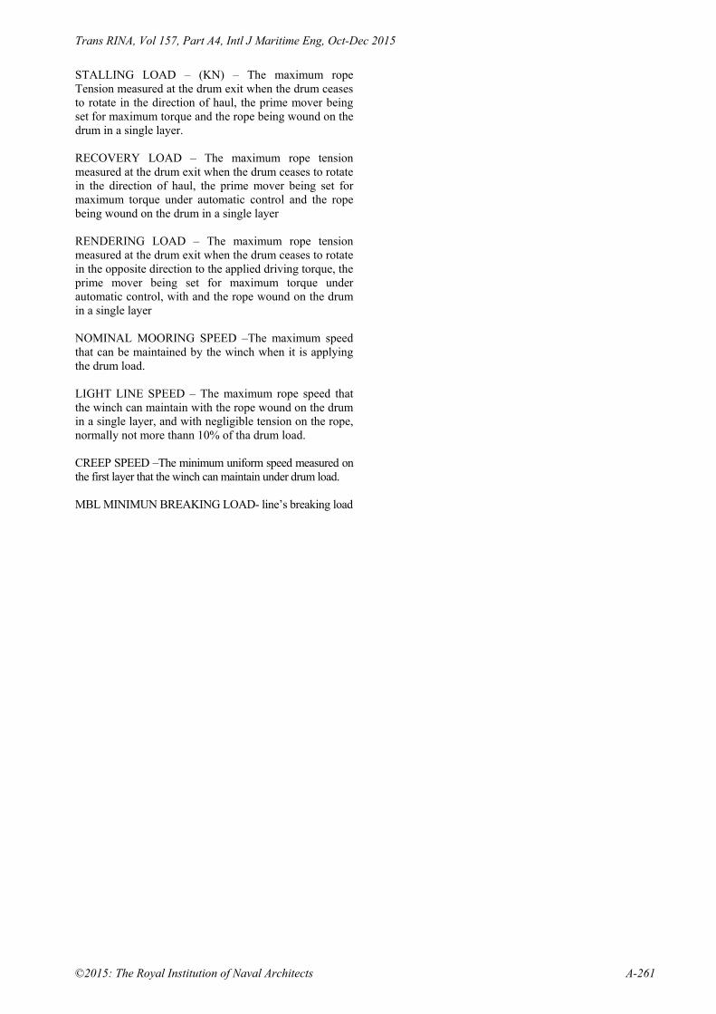
Trans RINA, Vol 157, Part A4, Intl J Maritime Eng, Oct-Dec 2015
©2015: The Royal Institution of Naval Architects A-261
STALLING LOAD – (KN) – The maximum rope Tension measured at the drum exit when the drum ceases to rotate in the direction of haul, the prime mover being set for maximum torque and the rope being wound on the drum in a single layer. RECOVERY LOAD – The maximum rope tension measured at the drum exit when the drum ceases to rotate in the direction of haul, the prime mover being set for maximum torque under automatic control and the rope being wound on the drum in a single layer RENDERING LOAD – The maximum rope tension measured at the drum exit when the drum ceases to rotate in the opposite direction to the applied driving torque, the prime mover being set for maximum torque under automatic control, with and the rope wound on the drum in a single layer NOMINAL MOORING SPEED –The maximum speed that can be maintained by the winch when it is applying the drum load. LIGHT LINE SPEED – The maximum rope speed that the winch can maintain with the rope wound on the drum in a single layer, and with negligible tension on the rope, normally not more thann 10% of tha drum load. CREEP SPEED –The minimum uniform speed measured on the first layer that the winch can maintain under drum load. MBL MINIMUN BREAKING LOAD- line’s breaking load

Trans RINA, Vol 157, Part A4, Intl J Maritime Eng, Oct-Dec 2015
A-262 ©2015: The Royal Institution of Naval Architects

Diseño de maquinaria de cubierta de buques, en base a una propuesta razonada de armonización reglamentaria Pág. 61
5.3. FISHING GROUNDS' INFLUENCE ON
TRAWLER WINCH DESIGN
Juan Carlos Carral Couce, Luis Carral Couce, Miguel Lamas Pardo, María Jesús Rodríguez Ocean Engineering 102 (2015) 136-145 DOI http://dx.doi.org/10.1016/j.oceaneng.2015.04.055

Diseño de maquinaria de cubierta de buques, en base a una propuesta razonada de armonización reglamentaria Pág. 62
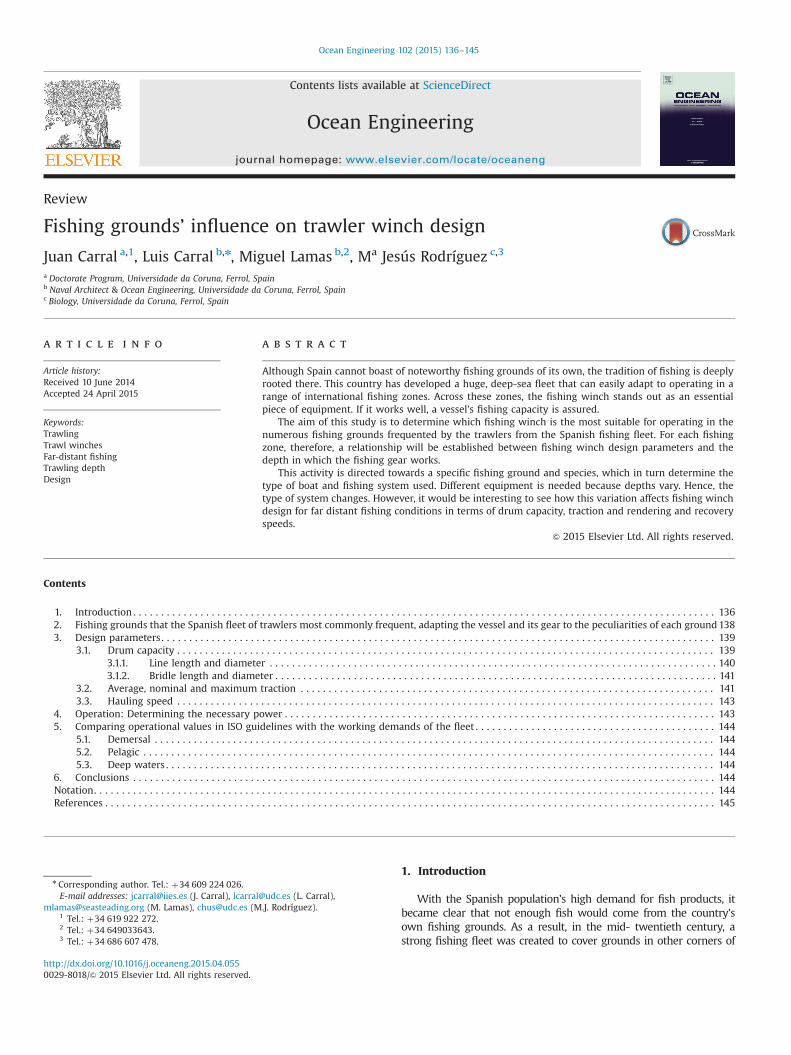
Review
Fishing grounds’ influence on trawler winch design
Juan Carral a,1, Luis Carral b,n, Miguel Lamas b,2, Ma Jesús Rodríguez c,3
a Doctorate Program, Universidade da Coruna, Ferrol, Spainb Naval Architect & Ocean Engineering, Universidade da Coruna, Ferrol, Spainc Biology, Universidade da Coruna, Ferrol, Spain
a r t i c l e i n f o
Article history:Received 10 June 2014Accepted 24 April 2015
Keywords:TrawlingTrawl winchesFar-distant fishingTrawling depthDesign
a b s t r a c t
Although Spain cannot boast of noteworthy fishing grounds of its own, the tradition of fishing is deeplyrooted there. This country has developed a huge, deep-sea fleet that can easily adapt to operating in arange of international fishing zones. Across these zones, the fishing winch stands out as an essentialpiece of equipment. If it works well, a vessel’s fishing capacity is assured.
The aim of this study is to determine which fishing winch is the most suitable for operating in thenumerous fishing grounds frequented by the trawlers from the Spanish fishing fleet. For each fishingzone, therefore, a relationship will be established between fishing winch design parameters and thedepth in which the fishing gear works.
This activity is directed towards a specific fishing ground and species, which in turn determine thetype of boat and fishing system used. Different equipment is needed because depths vary. Hence, thetype of system changes. However, it would be interesting to see how this variation affects fishing winchdesign for far distant fishing conditions in terms of drum capacity, traction and rendering and recoveryspeeds.
& 2015 Elsevier Ltd. All rights reserved.
Contents
1. Introduction . . . . . . . . . . . . . . . . . . . . . . . . . . . . . . . . . . . . . . . . . . . . . . . . . . . . . . . . . . . . . . . . . . . . . . . . . . . . . . . . . . . . . . . . . . . . . . . . . . . . . . . . 1362. Fishing grounds that the Spanish fleet of trawlers most commonly frequent, adapting the vessel and its gear to the peculiarities of each ground1383. Design parameters . . . . . . . . . . . . . . . . . . . . . . . . . . . . . . . . . . . . . . . . . . . . . . . . . . . . . . . . . . . . . . . . . . . . . . . . . . . . . . . . . . . . . . . . . . . . . . . . . . . 139
3.1. Drum capacity . . . . . . . . . . . . . . . . . . . . . . . . . . . . . . . . . . . . . . . . . . . . . . . . . . . . . . . . . . . . . . . . . . . . . . . . . . . . . . . . . . . . . . . . . . . . . . . . 1393.1.1. Line length and diameter . . . . . . . . . . . . . . . . . . . . . . . . . . . . . . . . . . . . . . . . . . . . . . . . . . . . . . . . . . . . . . . . . . . . . . . . . . . . . . . . 1403.1.2. Bridle length and diameter . . . . . . . . . . . . . . . . . . . . . . . . . . . . . . . . . . . . . . . . . . . . . . . . . . . . . . . . . . . . . . . . . . . . . . . . . . . . . . . 141
3.2. Average, nominal and maximum traction . . . . . . . . . . . . . . . . . . . . . . . . . . . . . . . . . . . . . . . . . . . . . . . . . . . . . . . . . . . . . . . . . . . . . . . . . . 1413.3. Hauling speed . . . . . . . . . . . . . . . . . . . . . . . . . . . . . . . . . . . . . . . . . . . . . . . . . . . . . . . . . . . . . . . . . . . . . . . . . . . . . . . . . . . . . . . . . . . . . . . . 143
4. Operation: Determining the necessary power . . . . . . . . . . . . . . . . . . . . . . . . . . . . . . . . . . . . . . . . . . . . . . . . . . . . . . . . . . . . . . . . . . . . . . . . . . . . . 1435. Comparing operational values in ISO guidelines with the working demands of the fleet . . . . . . . . . . . . . . . . . . . . . . . . . . . . . . . . . . . . . . . . . . . 144
5.1. Demersal . . . . . . . . . . . . . . . . . . . . . . . . . . . . . . . . . . . . . . . . . . . . . . . . . . . . . . . . . . . . . . . . . . . . . . . . . . . . . . . . . . . . . . . . . . . . . . . . . . . . 1445.2. Pelagic . . . . . . . . . . . . . . . . . . . . . . . . . . . . . . . . . . . . . . . . . . . . . . . . . . . . . . . . . . . . . . . . . . . . . . . . . . . . . . . . . . . . . . . . . . . . . . . . . . . . . . 1445.3. Deep waters . . . . . . . . . . . . . . . . . . . . . . . . . . . . . . . . . . . . . . . . . . . . . . . . . . . . . . . . . . . . . . . . . . . . . . . . . . . . . . . . . . . . . . . . . . . . . . . . . . 144
6. Conclusions . . . . . . . . . . . . . . . . . . . . . . . . . . . . . . . . . . . . . . . . . . . . . . . . . . . . . . . . . . . . . . . . . . . . . . . . . . . . . . . . . . . . . . . . . . . . . . . . . . . . . . . . 144Notation. . . . . . . . . . . . . . . . . . . . . . . . . . . . . . . . . . . . . . . . . . . . . . . . . . . . . . . . . . . . . . . . . . . . . . . . . . . . . . . . . . . . . . . . . . . . . . . . . . . . . . . . . . . . . . . 144References . . . . . . . . . . . . . . . . . . . . . . . . . . . . . . . . . . . . . . . . . . . . . . . . . . . . . . . . . . . . . . . . . . . . . . . . . . . . . . . . . . . . . . . . . . . . . . . . . . . . . . . . . . . . . 145
1. Introduction
With the Spanish population’s high demand for fish products, itbecame clear that not enough fish would come from the country’sown fishing grounds. As a result, in the mid- twentieth century, astrong fishing fleet was created to cover grounds in other corners of
Contents lists available at ScienceDirect
journal homepage: www.elsevier.com/locate/oceaneng
Ocean Engineering
http://dx.doi.org/10.1016/j.oceaneng.2015.04.0550029-8018/& 2015 Elsevier Ltd. All rights reserved.
n Corresponding author. Tel.: þ34 609 224 026.E-mail addresses: [email protected] (J. Carral), [email protected] (L. Carral),
[email protected] (M. Lamas), [email protected] (M.J. Rodríguez).1 Tel.: þ34 619 922 272.2 Tel.: þ34 649033643.3 Tel.: þ34 686 607 478.
Ocean Engineering 102 (2015) 136–145

the world. This was the case until the 1980s, with the III Law of the SeaConference under the auspices of the United Nations (NacionesUnidas, 1982). Coastal countries decided to extend their territorialwaters up to 200 mile. The 200 Mile Convention had several ramifica-tions: fishing grounds were lost; a number of fisheries disappeared;large-scale vessels were scheduled to be scrapped and many mixedjoint enterprises were established. Moreover, an itinerant fleet wascreated; it could go to an open fishing ground when it could not staywhere it was (Gil-Olcina and Gómez-Mendoza, 2001). Thanks to all ofthese factors, Spain had a vast far-distant fishing fleet that could adaptto the varied working conditions of different fishing grounds.
Even with all these difficulties, fishing has been a crucial sectorin Spain until recently. To provide an idea of the position oftrawling within the whole sector, 43% of the fleet – expressed ingross tonnage – is dedicated to trawling. This figure goes uppercentage-wise if one only considers fishing vessels headingtowards deep sea and middle water in sea fishing grounds over24 m in length (MAGRAMA, 2013).
Active groups are involved in trawling; they are searching forfish. With this method, almost any kind of sea-dwelling organismof commercial interest can be caught. Thus it is the most versatilemode of fishing with the greatest range of adaptation andapplication.
The origins of trawling have been lost to time. However,technological advances mean that it is possible to fish in deeperwaters farther and farther away (Trout, 1967; Solovyov andCherniavsky, 2013). At the same time, catches are becoming scarcer.These two factors mean that improvements have to be made tofishing systems (Santos and Nuñez, 1994).
With variations in depth, trawling methods have to adapt tohow the fishing gear is operated and the type of manoeuvres used.Benthic or demersal trawling may take place close to or along thebottom of the seabed, respectively. Alternatively midwater fishingentails pelagic trawling. Trawling from the stern-side with a ramp isthe most common type of manoeuvre. The nets are cast by means ofa ramp positioned on the transom and later spread out over thedeck. The deck has to be quite long so that the large nets can behandled while leaving space for the trawling winch at one end ofthe stern. As a result, the bridge has to be positioned in forwarddeck (Fyson, 1985; Santos and Nuñez, 1994) (Fig. 1).
With the method used by ramped stern trawlers, the vesselsmust be mid- to large-sized and use huge nets. It is precisely thebigger dimensions of the vessels and their gear that make itnecessary to employ a technologically complex fishing winchwhose characteristics make it possible to carry out the man-oeuvres (Carral, 2005).
More suitable than their single counterparts, twin decks arecommon when length exceeds 25–30 m. Blah (Santos and Nuñez,1994 p. 135) explains why the twin configuration works better. Thefish can be taken below deck, where it can be processed moreefficiently and comfortably. Moreover, the hold, pens and factoryhave a greater capacity, with more space for more sophisticatedequipment (Fig. 2).
Winches are used for manoeuvring the fishing gear. Thesewinches are made up of the components that handle sweep lines,warps and cargo runners for the codend and drum ends. The wayin which this equipment is positioned on the deck may vary(Fig. 3). Two independent winches may be used, one on each side,or a net drum on the bridge deck. In the latter case, only one,centrally located winch is employed. It has pulling drums on eachside to leave space in the middle for the net drum (Carral andCarral, 1999). The sweep lines and warp can be stowed in the sameor separate drums (Santos and Nuñez, 1994 p. 138). The winch forhoisting the codend is usually kept to one side in the deck.
Guidelines for the fishing vessel to operate safely are a concernfor both the state of the fishing flag and the ship owner. In terms ofthe state, there are two frameworks: its own regulations (ISO, DIN,and so on) and those imposed on a global scale (through the IMOor ILO, for instance). Ship owners are obliged to respect theregulations set by the classification societies they have chosenfor their vessels. To understand the implementation guidelines fordesigning trawl winches, it is necessary to look at the full range ofregulations.
The International Standards Organisation (ISO) relies on thecollaboration of experts from more than 156 countries. Amongthese are most of the European states. This entity has its ownimplementation guidelines for trawl – winches through the ISO –
TC 8 Technical Committee for Ships and Marine Technology. ISO6115:1988 – Shipbuilding – Trawl winches (ISO, 1988) serves as abenchmark for designing and testing trawl winches. However, itscontents also deal with other fishing gear components. Table 1
Fig. 1. Coastal Trawler. Longitudinal cross-section of the winch and bridge. Source:author’s own.
Fig. 2. Twin deck Deep sea Trawler arranged with trawl winches: trawl winches,bridle winches, auxiliary winches and net drum. Source: author’s own.
J. Carral et al. / Ocean Engineering 102 (2015) 136–145 137

includes the implementation guidelines for designing the compo-nents for fishing manoeuvres.
With trawling, the vessel type and fishing method are deter-mined by the fishing ground and species. Because it is operating indifferent fishing grounds, the fishing gear has to work in a range of
depths. Depth is one of the key factors in determining the fishingmethod (Lee et al., 2001). It therefore makes sense to know theeffect this variable has on fishing winch design. Design parametersaffected by depth include drum capacity; average, nominal andmaximum traction; and hauling speed.
2. Fishing grounds that the Spanish fleet of trawlers mostcommonly frequent, adapting the vessel and its gear to thepeculiarities of each ground
In part the Spanish fishing fleet carries out trawling operationsin international fishing grounds. The figures provide an idea of thescale: this fleet is second biggest globally and boasts 182 vessels ofoutstanding length (MAGRAMA, 2013).
This activity has been influenced by the changes that havetaken place in Maritime Law. These changes, for instances, led tojoint enterprises being created so that vessels could fish in thegrounds belonging to other countries. Thus, Table 2 specifies thevessels that operate under the Spanish flag and those that are inthe hands of Spanish companies. Official data from MAGRAMA(2013) have been adjusted with information provided by shipowner associations. Table 2 is related to the fishing grounds withthe largest number of deep sea and middle water fleets. It alsoprovides geographical details and the names of the species caughtby the fishing fleets (FAO, 2007; MAGRAMA, 2013).
First the fishing method is determined to match fishing groundconditions and species. The next step to find the most suitablefishing vessel and gear to optimise the operation (Martinez-Lopezet al., 2012). Table 3 divides this process of adaptation into phases,from opting for the fishing ground and method to finding thecorrect vessel and gear.
Table 1Implementation guidelines for designing the components for fishing manoeuvres.Source: author’s own.
Classification societies IMO/flag states ISO
Fishing winch Not included National regulations may exist 6115—Trawl winches6482—Warping end profiles2408—Steel wire rope for general purposes7825—Deck machinery, general requirements
Net drum Not included National regulations may exist 6115—Trawl winches6482—Warping end profiles7825—Deck machinery, general requirements
Manoeuvring components Lifting eyes and appliances National regulations may exist 2408—Steel wire rope for general purposes1141—Fibre ropes3913—Welded steel bollards
Table 2Exploitation data about fishing grounds in which the Spanish trawling fleet operates- year 2014.Source: ARVI—Vigo fishing vessel owners Association.
Fishing fleet Details Location Species Nº ofvessels
Galicia–Cantábrico Galician continental platform andSpanish Cantabrian coast
– – 50
Gran Sol Gran Sol Northern AtlanticEuropean Community grounds
Off Brittany and to the south of the Irish Republiccoastline
Hake, megrim, monkfish and mackerel 35
N.A.F.O. (North AtlanticFishery Organization)
NW Atlantic or Canadian ground To the north of Hatteras Cape, New York towardsthe north and west coast of Greenland
Cod, plaice, blackbelly rosefish andGreenland halibut
11
Hatton Bank NE Atlantic grounds in area underNAFO
To the NW of Irish Republic and S of Iceland Roundnose grenadier, bullseye, Greenlandhalibut and blackbelly rosefish
8
Mauritania Fishing banks off Mauritania Off the Mauritanian coast Black hake, cephalopods, tuna andcrustaceans
15
Falklands (Malvinas) SW Atlantic or Falklands Off the Falkland Islands, within its territorial water Hake 25Namibia SW Atlantic. Area 47 W of South Africa, off Namibia Hake, monkfish, brotula and broadtail
squid26
Fig. 3. Possible ways to position the fishing gear on the deck: split trawl winchesand a single winch. In both cases, a net drum is used. Source: author’s own.
J. Carral et al. / Ocean Engineering 102 (2015) 136–145138
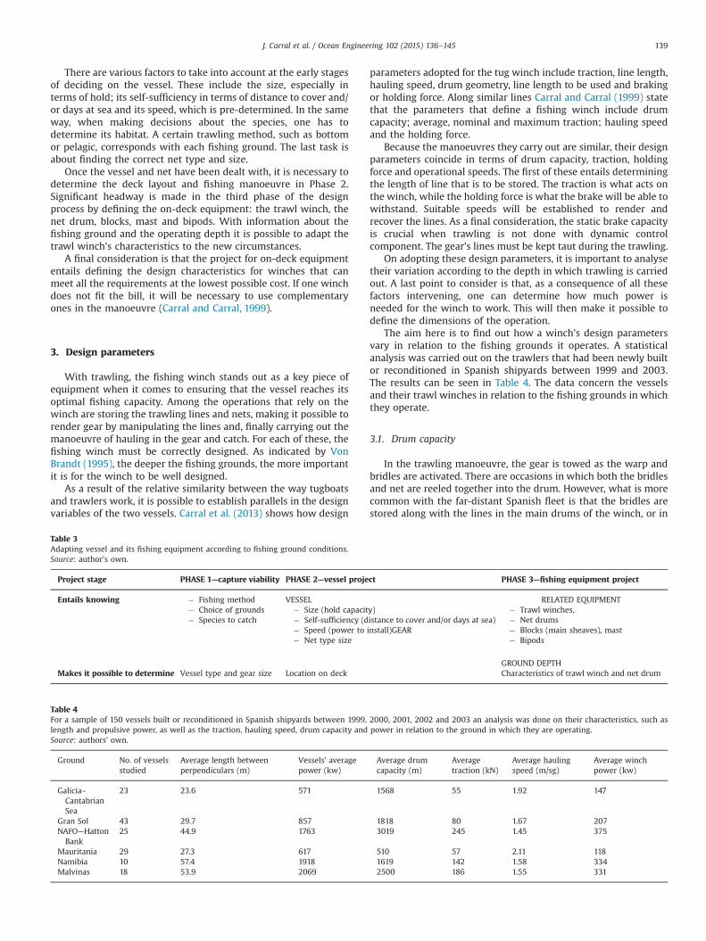
There are various factors to take into account at the early stagesof deciding on the vessel. These include the size, especially interms of hold; its self-sufficiency in terms of distance to cover and/or days at sea and its speed, which is pre-determined. In the sameway, when making decisions about the species, one has todetermine its habitat. A certain trawling method, such as bottomor pelagic, corresponds with each fishing ground. The last task isabout finding the correct net type and size.
Once the vessel and net have been dealt with, it is necessary todetermine the deck layout and fishing manoeuvre in Phase 2.Significant headway is made in the third phase of the designprocess by defining the on-deck equipment: the trawl winch, thenet drum, blocks, mast and bipods. With information about thefishing ground and the operating depth it is possible to adapt thetrawl winch’s characteristics to the new circumstances.
A final consideration is that the project for on-deck equipmententails defining the design characteristics for winches that canmeet all the requirements at the lowest possible cost. If one winchdoes not fit the bill, it will be necessary to use complementaryones in the manoeuvre (Carral and Carral, 1999).
3. Design parameters
With trawling, the fishing winch stands out as a key piece ofequipment when it comes to ensuring that the vessel reaches itsoptimal fishing capacity. Among the operations that rely on thewinch are storing the trawling lines and nets, making it possible torender gear by manipulating the lines and, finally carrying out themanoeuvre of hauling in the gear and catch. For each of these, thefishing winch must be correctly designed. As indicated by VonBrandt (1995), the deeper the fishing grounds, the more importantit is for the winch to be well designed.
As a result of the relative similarity between the way tugboatsand trawlers work, it is possible to establish parallels in the designvariables of the two vessels. Carral et al. (2013) shows how design
parameters adopted for the tug winch include traction, line length,hauling speed, drum geometry, line length to be used and brakingor holding force. Along similar lines Carral and Carral (1999) statethat the parameters that define a fishing winch include drumcapacity; average, nominal and maximum traction; hauling speedand the holding force.
Because the manoeuvres they carry out are similar, their designparameters coincide in terms of drum capacity, traction, holdingforce and operational speeds. The first of these entails determiningthe length of line that is to be stored. The traction is what acts onthe winch, while the holding force is what the brake will be able towithstand. Suitable speeds will be established to render andrecover the lines. As a final consideration, the static brake capacityis crucial when trawling is not done with dynamic controlcomponent. The gear’s lines must be kept taut during the trawling.
On adopting these design parameters, it is important to analysetheir variation according to the depth in which trawling is carriedout. A last point to consider is that, as a consequence of all thesefactors intervening, one can determine how much power isneeded for the winch to work. This will then make it possible todefine the dimensions of the operation.
The aim here is to find out how a winch’s design parametersvary in relation to the fishing grounds it operates. A statisticalanalysis was carried out on the trawlers that had been newly builtor reconditioned in Spanish shipyards between 1999 and 2003.The results can be seen in Table 4. The data concern the vesselsand their trawl winches in relation to the fishing grounds in whichthey operate.
3.1. Drum capacity
In the trawling manoeuvre, the gear is towed as the warp andbridles are activated. There are occasions in which both the bridlesand net are reeled together into the drum. However, what is morecommon with the far-distant Spanish fleet is that the bridles arestored along with the lines in the main drums of the winch, or in
Table 3Adapting vessel and its fishing equipment according to fishing ground conditions.Source: author’s own.
Project stage PHASE 1—capture viability PHASE 2—vessel project PHASE 3—fishing equipment project
Entails knowing � Fishing method� Choice of grounds� Species to catch
VESSEL RELATED EQUIPMENT� Size (hold capacity)� Self-sufficiency (distance to cover and/or days at sea)� Speed (power to install)GEAR� Net type size
� Trawl winches,� Net drums� Blocks (main sheaves), mast� Bipods
GROUND DEPTHMakes it possible to determine Vessel type and gear size Location on deck Characteristics of trawl winch and net drum
Table 4For a sample of 150 vessels built or reconditioned in Spanish shipyards between 1999, 2000, 2001, 2002 and 2003 an analysis was done on their characteristics, such aslength and propulsive power, as well as the traction, hauling speed, drum capacity and power in relation to the ground in which they are operating.Source: authors’ own.
Ground No. of vesselsstudied
Average length betweenperpendiculars (m)
Vessels’ averagepower (kw)
Average drumcapacity (m)
Averagetraction (kN)
Average haulingspeed (m/sg)
Average winchpower (kw)
Galicia–CantabrianSea
23 23.6 571 1568 55 1.92 147
Gran Sol 43 29.7 857 1818 80 1.67 207NAFO—HattonBank
25 44.9 1763 3019 245 1.45 375
Mauritania 29 27.3 617 510 57 2.11 118Namibia 10 57.4 1918 1619 142 1.58 334Malvinas 18 53.9 2069 2500 186 1.55 331
J. Carral et al. / Ocean Engineering 102 (2015) 136–145 139
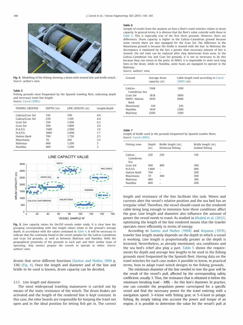
drums that serve different functions (Santos and Nuñez, 1994 p.138) (Fig. 4). Once the length and diameter and of the line andbridle to be used is known, drum capacity can be decided.
3.1.1. Line length and diameterThe most widespread trawling manoeuvre is carried out by
means of the static resistance of the winch. The drum brakes areactivated and the length of the rendered line is kept constant. Inthis case, the otter boards are responsible for keeping the trawl netopen and in the ideal position for letting fish get in. The correct
length and resistance of the line facilitate this task. Waves andcurrents alter the vessel’s relative position and the sea bed has anirregular relief. Therefore, the vessel should count on the renderedcable being long enough to minimize how these conditions affectthe gear. Line length and diameter also influence the amount ofpower the vessel needs to trawl. As studied in Khaled et al. (2012),optimizing the length of the line rendered means that the trawleroperates more efficiently in terms of energy.
According to Santos and Nuñez (1994) and Koyama (1970),trawler line length mainly depends on the depth in which a vesselis working. Line length is proportionally greater as the depth islessened. Nevertheless, as already mentioned, sea conditions andthe sea bed’s relief also play a part. Table 5 shows the require-ments for depth and average line lengths to be used in the fishinggrounds most frequented by the Spanish fleet. Having data on thetrawl winches for each case makes it possible to know, in practicalterms, how to adapt trawl winch designs to the fishing grounds.
The minimum diameter of the line needed to tow the gear will bethe result of the vessel’s pull, affected by the corresponding safetycoefficient, usually 3. Thus, the resistance that is obtained is below theminimum breaking load – MBL – for this line’s diameter. In practice,one can consider the propulsion power curve/speed for a specificvessel and find the necessary power for the trawl entering with anavigation speed: 3–4 knot with fishing gear, or 5–6 knot in pelagicfishing. By simply taking into account the power and torque of anengine, it is possible to determine the value for the vessel’s pull at
Fig. 4. Modelling of the fishing showing a drumwith stowed line and bridle winch.Source: author’s own.
Table 5Fishing grounds most frequented by the Spanish trawling fleet, indicating depthand necessary trawl line length.Source: Carral (2005).
FISHING GROUND DEPTH (m) LINE LENGTH (m) Length/depth
Galicia/Gran Sol 150 700 4.6Galicia/Gran Sol 250 1.100 4.4Gran Sol 350 1.500 4.3Gran Sol 500 1.800 3.6N.A.F.O. 1500 2.900 1.9N.A.F.O. 1800 3.000 1.7Hatton Bank 700 1.750 2.5Mauritania 70 245 3.5Malvinas 400 1.200 3Namibia 400 1.200 3
0
500
1000
1500
2000
2500
3000
3500
0 20 40 60 80 100 120 140 160
DR
UM
CA
PA
CIT
Y (m
)
VESSEL SAMPLE Nº
LINE CAPACITY VALUENAFO
MALVINAS
MAURITANIA
NAMIBIA
GRAN SOL
GALICIA-CANTABRIAN
Fig. 5. Line capacity values for the150 vessels under study. It is clear how thegrouping corresponding with line length values relate to the ground’s averagedepth, in accordance with the values contained in Table 4. It will be necessary toindicate that the continuity found in the vessel samples for the Galicia–Cantabrianand Gran Sol grounds, as well as between Malvinas and Namibia. With thegeographical proximity of the grounds in each pair and their similar ways ofoperating, ship owners prepare the vessels to operate in either. Source:authors’ own.
Table 6Sample of results from the analysis on how a fleet’s trawl winches relates to drumcapacity. In general terms, it is obvious that the fleet’s value coincide with those inTable 5. This is especially true of the first three grounds. However, there aredifferences. Drum capacity is higher in the Galicia–Cantabrian ground becausesome vessels there are also equipped for the Gran Sol. The difference in theMauritania ground is because the bridle is stowed with the line. In Malvinas thediscrepancy is explained by the fact a greater than necessary amount of line isstowed; the tail ends can be replaced after they deteriorate from wear. In theGalicia–Cantabrian Sea and Gran Sol grounds, it is not so necessary to do thisbecause they can return to the ports. In NAFO, it is impossible to stow such longlines in the drum, while in Namibia, some boats are equipped to operate in theMalvinas.Source: authors’ own.
Ground Average drumcapacity (m)
Cable length used according to Carral(2005) (m)
Galicia–Cantabrian Sea
1568 1100
Gran Sol 1818 1800NAFO—HattonBank
3019 3000
Mauritania 510 245Namibia 1619 1200Malvinas 2500 1200
Table 7Length of bridle used in the grounds frequented by Spanish trawler fleets.Source: Carral (2005).
Fishing zone Depth(m)
Bridle length (m),Demersal fishing
Bridle length (m),Seabed fishing
Galicia–CantabrianSea
250 250 150
Gran Sol 300 400 300N.A.F.O. 1.800 – 400Hatton Bank 700 – 200Mauritania 70 300 300Malvinas 400 – 100Namibia 400 – 200
J. Carral et al. / Ocean Engineering 102 (2015) 136–145140

trawling speed. This is the vessel’s capacity to tow its gear in its totality(Santos and Nuñez, 1994).
As explained in Carral and Carral (1999), if the gear is entangledwith an obstacle on the seabed, the resistance that the lines willwithstand – SWL – corresponds to the total bollard pull of thevessel along with its winch’s traction capacity. Under theseunusual circumstances, the safety coefficient will be reduced to avalue slightly below 2.
As for the diameter, De la Cueva (1987) proposes an approx-imate formula that links the main engine’s power with thediameter of the line used.
D¼ 18þ0:0034 � P ð1ÞMore commonly, trawling relies on steel cables made up
of strands and wires that follow the requirement of 6�12þ1y6�19þ1. Their MBL characteristics and unitary weights areprovided in the article (Carral and Carral, 1999).
A statistical analysis was carried out to produce Fig. 5. Here therelationship is shown between the ground and the winch’s capacity tocontain the suitable amount of line to carry out the manoeuvre.Similarly Table 6 shows the capacities employed in the Spanish fleet incomparison with the table contained in Carral (2005).
3.1.2. Bridle length and diameterThe bridle serves two functions. It keeps the gear as stable as
possible by damping the vibrations given off by the vessel. At thesame time, it defines the working height of the net (Carral andCarral, 1999). In the latter case, bridle length is influenced by thespecies that will be caught. Bridle length is lower when ocean bedspecies are sought by means of bentonic or demersal trawling thanit is in the case of mid-water operations in pelagic catches (Carral,
2005). Table 7 includes data on the bridle length used in differentfishing grounds, depending if it is for demersal or seabed fishing.
The bridle is similar to the line; it must withstand the pull ofthe vessel when trawling is carried out and when the gear getsentangled along the seabed. To keep the gear stable at the desiredheight, the bridle should withstand the necessary weight. This iswhy it is necessary to establish the weight per 100 m of length.Table 8 includes the characteristics of the polyethene bridlecommonly used in Spanish trawlers. Data include the MBL, theunit weight and the bridle diameter. A working guideline used byship masters for the bridle diameter is that it is double the onethat corresponds with the line that has been chosen.
3.2. Average, nominal and maximum traction
A fishing winch’s traction refers to its capacity to lift the gearand catch when it is time to haul the gear in. The impacting torquecan be seen as a constant during the operation. Thus, the value forthe traction produced by the winch over the line varies inaccordance with the layer of winding that is considered. For thisreason, the traction value should be accompanied by the corre-sponding guidelines for the diameter. In general, three types oftraction value – average, nominal and maximum – that make itpossible to know the trawl winch characteristics (Carral andCarral, 1999).
Average traction is the value commonly employed by themanufacturers and ship owners. It is related to the drum mechan-ism’s traction on the average diameter. This average value isobtained as half the sum of minimum and maximum diametersof the drum. It is a given that the bottom layers of line have alower development than those at the top. Therefore this tractionvalue is not going to coincide with the one that the machine haswhen half the cable is reeled in. This difference will vary depend-ing on factors such as the drum geometry and the relationshipbetween the existing bridle and line lengths.
Nominal traction will be the winch’s pull value when the drumhas 2/3 of its line capacity, but no bridle. As the line length is atleast three times the depth of the zone of work, this valueapproaches the one needed for all of the fishing gear’s componentsto cast: Otter board, net, seine floats, iron bobbins, bridles and athird of the total line length.
In commercial fishing, this value is seldom used as its differ-ence with respect to the value for the average traction ends upbeing very small. It is thus necessary to carry out a specificcalculation for each line length (nominal diameter). Although itis not very useful to calculate this value, it is a good idea to checkthat winch traction is sufficient to raise the entire set of fishinggear and the catch from the seabed. In this case, the necessarytraction will be expressed by the formula proposed by Carral(2005):
T ¼ 0:87 � Pc
3þ Pp
� �þb � PmþPað Þþ Ra ð2Þ
This is the usual way to carry out testing on winch design forconventional fishing boats. However, it is a different case when itcomes to designing equipment meant to hold an extremely longline, as with vessels working in very deep fishing grounds. Here, itwill be worth comparing the value taken by expression (2). This isrelated to the length of line rendered in each case Pc). The tractionvalues are in the successive winding layers of the drum. This lastvalue can be calculated according with expression (3) obtainedexperimentally to determine, in the case of layer “n”, the winchtraction is:
Tn ¼ Tnomdeþdið Þ
diþ2 � n�1ð Þ � D cos 30ð3Þ
Table 8Characteristics of the MBL unit weight and diameter of the polyethene bridle inSpanish trawlers.Source: Carral (2005).
Diameter (mm) MBL (kN) weight (kg/100 m)
30 135 10036 190 13040 235 17552 390 210
Table 9Variation in average traction in fishing vessels with the operating depth.Source: authors’ own.
FISHING ZONE DEPTH (m) AVERAGE TRACTION (kN)
Mauritania 70 57Galicia and Cantabrian Sea 150 55Gran Sol 350 80Malvinas and Namibia 400 142
1000 186N.A.F.O. and Hatton Bank 1800 245
Table 10Variation in the fishing winch’s lifting speed in relation to the operational depth.Source: authors’own.
FISHING ZONE DEPTH (m) HOISTING SPEED (m/sg)
Mauritania 70 2.11Galicia–Cantabrian Sea 150 1.92Gran Sol 350 1.67Namibia 400 1.58Malvinas 1000 1.55N.A.F.O. 1800 1.45
J. Carral et al. / Ocean Engineering 102 (2015) 136–145 141
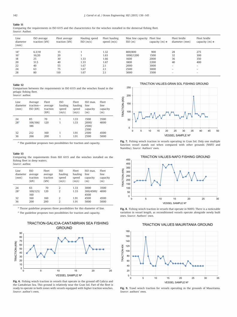
Table 11Comparing the requirements in ISO 6115 and the characteristics for the winches installed in the demersal fishing fleet.Source: Author.
Linediameter(mm)
ISO averagetraction (kN)
Fleet averagetraction (kN)
Hauling speedISO (m/s)
Fleet haulingspeed (m/s)
Max line capacityISO (m)
Fleet linecapacity (m) n
Fleet bridlediameter (mm)
Fleet bridlecapacity (m) n
14a 6.3/10 15 1 1.32 800/800 900 28 27516a 16/20 20 1 1.63 1000/1200 1500 32 30018 25 30 1.33 1.66 1600 2000 36 35020 31.5 40 1.33 1.67 1800 2200 40 40022 40 55 1.67 2.1 2000 3000 – –
24 63 75 1.67 2.1 2500 3000 – –
28 80 110 1.67 2.1 3000 3500 – –
a The guideline proposes two possibilities for traction and capacity.
Table 12Comparison between the requirements in ISO 6115 and the winches found in thepelagic fishing fleet.Source: author.
Linediameter(mm)
Averagetraction—ISO (kN)
Fleetaveragetraction(kN)
ISOhaulingspeed(m/s)
Fleethaulingspeed(m/s)
ISO max.linecapacity(m)
Fleetlinecapacity(m)
24 85 70 1 1.33 1500 350028a 106/166/
186120 1 1.33 2000/
2500/2500
4000
32 212 160 1 1.91 2500 450036 266 200 1 1.91 2500 5000
a The guideline proposes two possibilities for traction and capacity.
Table 13Comparing the requirements from ISO 6115 and the winches installed on thefishing fleet in deep waters.Source: author.
Linediameter(mm)
ISOaveragetraction(kN)
Fleetaveragetraction(kN)
ISOhaulingspeed(m/s)
Fleethaulingspeed(m/s)
ISO max.linecapacity(m)
Fleetlinecapacity(m)
24 63 70 2 1.33 3000 350028a 100/125/
160120 2 1.33 300/4500/
45004000
32 160 160 2 1.91 4500 450036 200 200 2 1.91 5000 5000
a Thssse guideline proposes three possibilities for this diameter of line.
0102030405060708090
0 5 10 15 20 25
TRA
CTI
ON
-(K
N)
VESSEL SAMPLE Nº
TRACTION-GALICIA-CANTABRIAN SEA FISHING GROUND
Fig. 6. Fishing winch traction in vessels that operate in the ground off Galicia andthe Cantabrian Sea. This ground is relatively near the Gran Sol. Part of the fleet isready to operate in both zones with vessels equipped with higher traction winches.Source: author’s own.
0
50
100
150
200
250
0 5 10 15 20 25 30 35 40 45 50
TRA
CTI
ON
-(K
N)
VESSEL SAMPLE Nº
TRACTION VALUES-GRAN SOL FISHING GROUND
Fig. 7. Fishing winch traction in vessels operating in Gran Sol. Only one multiplefunction vessel stands out when compared with other grounds (NAFO andNamibia). Source: Authors’ own.
050
100150200250300350400450
0 5 10 15 20 25 30
TRA
CTI
ON
-(K
N)
VESSEL SAMPLE Nº
TRACTION VALUES-NAFO FISHING GROUND
Fig. 8. Fishing winch traction in vessels that operate in NAFO. There is a noticeablevariation in vessel length, as reconditioned vessels operate alongside newly builtones. Source: Authors’ own.
0
20
40
60
80
100
120
140
160
180
0 5 10 15 20 25 30 35
TRA
CTI
ON
-KN
VESSEL SAMPLE Nº
TRACTION VALUES MAURITANIA GROUND
Fig. 9. Trawl winch traction for vessels operating in the grounds of Mauritania.Source: authors’ own.
J. Carral et al. / Ocean Engineering 102 (2015) 136–145142
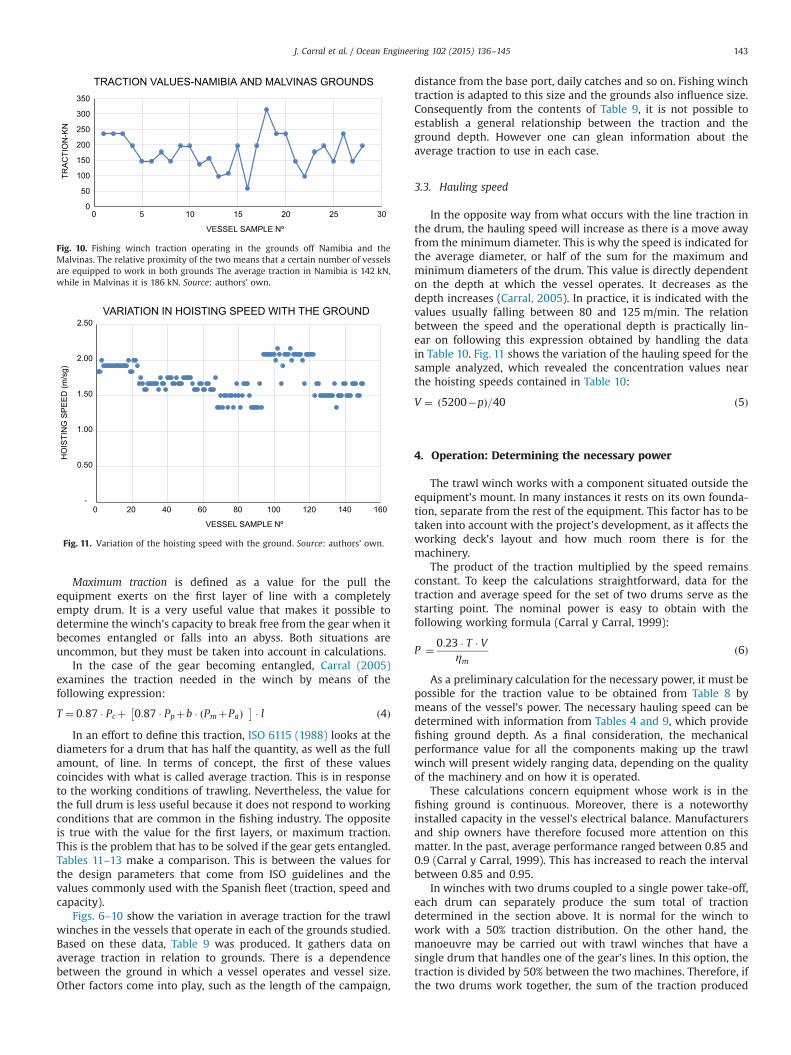
Maximum traction is defined as a value for the pull theequipment exerts on the first layer of line with a completelyempty drum. It is a very useful value that makes it possible todetermine the winch’s capacity to break free from the gear when itbecomes entangled or falls into an abyss. Both situations areuncommon, but they must be taken into account in calculations.
In the case of the gear becoming entangled, Carral (2005)examines the traction needed in the winch by means of thefollowing expression:
T ¼ 0:87 � Pcþ 0:87 � Ppþb � PmþPað Þ� � � l ð4ÞIn an effort to define this traction, ISO 6115 (1988) looks at the
diameters for a drum that has half the quantity, as well as the fullamount, of line. In terms of concept, the first of these valuescoincides with what is called average traction. This is in responseto the working conditions of trawling. Nevertheless, the value forthe full drum is less useful because it does not respond to workingconditions that are common in the fishing industry. The oppositeis true with the value for the first layers, or maximum traction.This is the problem that has to be solved if the gear gets entangled.Tables 11–13 make a comparison. This is between the values forthe design parameters that come from ISO guidelines and thevalues commonly used with the Spanish fleet (traction, speed andcapacity).
Figs. 6–10 show the variation in average traction for the trawlwinches in the vessels that operate in each of the grounds studied.Based on these data, Table 9 was produced. It gathers data onaverage traction in relation to grounds. There is a dependencebetween the ground in which a vessel operates and vessel size.Other factors come into play, such as the length of the campaign,
distance from the base port, daily catches and so on. Fishing winchtraction is adapted to this size and the grounds also influence size.Consequently from the contents of Table 9, it is not possible toestablish a general relationship between the traction and theground depth. However one can glean information about theaverage traction to use in each case.
3.3. Hauling speed
In the opposite way from what occurs with the line traction inthe drum, the hauling speed will increase as there is a move awayfrom the minimum diameter. This is why the speed is indicated forthe average diameter, or half of the sum for the maximum andminimum diameters of the drum. This value is directly dependenton the depth at which the vessel operates. It decreases as thedepth increases (Carral, 2005). In practice, it is indicated with thevalues usually falling between 80 and 125 m/min. The relationbetween the speed and the operational depth is practically lin-ear on following this expression obtained by handling the datain Table 10. Fig. 11 shows the variation of the hauling speed for thesample analyzed, which revealed the concentration values nearthe hoisting speeds contained in Table 10:
V ¼ ð5200�pÞ=40 ð5Þ
4. Operation: Determining the necessary power
The trawl winch works with a component situated outside theequipment’s mount. In many instances it rests on its own founda-tion, separate from the rest of the equipment. This factor has to betaken into account with the project’s development, as it affects theworking deck’s layout and how much room there is for themachinery.
The product of the traction multiplied by the speed remainsconstant. To keep the calculations straightforward, data for thetraction and average speed for the set of two drums serve as thestarting point. The nominal power is easy to obtain with thefollowing working formula (Carral y Carral, 1999):
P ¼ 0:23 � T � Vηm
ð6Þ
As a preliminary calculation for the necessary power, it must bepossible for the traction value to be obtained from Table 8 bymeans of the vessel’s power. The necessary hauling speed can bedetermined with information from Tables 4 and 9, which providefishing ground depth. As a final consideration, the mechanicalperformance value for all the components making up the trawlwinch will present widely ranging data, depending on the qualityof the machinery and on how it is operated.
These calculations concern equipment whose work is in thefishing ground is continuous. Moreover, there is a noteworthyinstalled capacity in the vessel’s electrical balance. Manufacturersand ship owners have therefore focused more attention on thismatter. In the past, average performance ranged between 0.85 and0.9 (Carral y Carral, 1999). This has increased to reach the intervalbetween 0.85 and 0.95.
In winches with two drums coupled to a single power take-off,each drum can separately produce the sum total of tractiondetermined in the section above. It is normal for the winch towork with a 50% traction distribution. On the other hand, themanoeuvre may be carried out with trawl winches that have asingle drum that handles one of the gear’s lines. In this option, thetraction is divided by 50% between the two machines. Therefore, ifthe two drums work together, the sum of the traction produced
0
50
100
150
200
250
300
350
0 5 10 15 20 25 30
TRA
CTI
ON
-KN
VESSEL SAMPLE Nº
TRACTION VALUES-NAMIBIA AND MALVINAS GROUNDS
Fig. 10. Fishing winch traction operating in the grounds off Namibia and theMalvinas. The relative proximity of the two means that a certain number of vesselsare equipped to work in both grounds The average traction in Namibia is 142 kN,while in Malvinas it is 186 kN. Source: authors’ own.
-
0.50
1.00
1.50
2.00
2.50
0 20 40 60 80 100 120 140 160
HO
ISTI
NG
SP
EE
D (m
/sg)
VESSEL SAMPLE Nº
VARIATION IN HOISTING SPEED WITH THE GROUND
Fig. 11. Variation of the hoisting speed with the ground. Source: authors’ own.
J. Carral et al. / Ocean Engineering 102 (2015) 136–145 143

will be the same as the one calculated earlier. In individual work,each operation could exert 65% of the total traction.
5. Comparing operational values in ISO guidelines with theworking demands of the fleet
An analysis was carried out on the characteristics of the trawlwinches installed on trawlers built between 1999 and 2003. Thesecharacteristics were then compared with the guidelines in ISO6115, as shown in Tablas 11, 12 and 13. Similarly, conclusions havebeen drawn for every piece of equipment intended for demersal,pelagic and bottom trawling.
5.1. Demersal
� The average traction for the fleet’s winches is higher than theone indicated in ISO 6115 for any line diameter.
� Similarly the habitual hauling speeds for the equipmentinstalled in Spanish vessels are clearly higher than those foundin ISO guidelines.
� In the machinery for lines whose diameter is below 22 mm,both the bridle and the line are stored in the same drum. Thismeans that the size of these drums is much greater.
� Because Spain does not have its own fishing grounds, much ofthe machinery is built on a larger scale than usual so that it canfulfil a variety of purposes. This would allow them to work inother fishing grounds in the future.
5.2. Pelagic
� As for machinery manufactured for pelagic or medium depthfishing, it is once again the case that the speeds and capacitiesare higher than those provided by the guidelines for anydiameter of line.
� Nevertheless, winch traction will be below those from ISO.
5.3. Deep waters
� Here, tractions and capacities correspond for all line diameters.Nevertheless, the speeds relating to 24 and 28 mm diametersfall below those found in ISO guidelines.
� By the time fishing campaigns started in deep waters, thevessels had already been built. As Spain did not have its ownfishing ground, the majority of trawl winches had to be adaptedfor deeper waters. These changes were limited to extendingdrum capacity; the rest of the machinery operated as before.For this reason, the speed and average traction are repeated.
6. Conclusions
The Spanish trawler fleet involved in Atlantic fishing campaignshave to work in extremely varied fishing grounds. Focusing on thedepth alone, in the Mauritania ground or the Canary–Sahara banksituated 70 m below the surface, the fishing crew can work with avery low cable length (300 m). In North Atlantic (NAFO) waters,the crews have to work at a depth of 1800 m with cable lengthsgreater than 3000 m. Between these two extreme cases, the othergrounds have middle—ranging depths. As they are relatively nearto each other, the vessels can take turns to carry out campaigns intwo different zones, such as Galicia and Gran-Sol, Hatton Bank andNAFO, or Namibia and Malvinas.
A key piece of equipment in trawling manoeuvres is the trawlwinch. To define this piece of equipment, as indicated in Carral and
Carral (1999), it is necessary to determine the following threeparameters: drum capacity, dynamic traction and holding andhauling speeds. When working with different depths, these threeparameters should be adapted accordingly.
The drum can handle metal line and/or bridle. Another decisionto make is whether the two elements get stowed together in thesame drum, or if they should be kept separate. The lengths of them(cable and bridle) vary according to the depth of the fishingground. This is reflected in Tables 5 and 7. In terms of theirdiameter, this is related to the vessel’s power.
In terms of the equipment’s traction, the dynamic traction is tobe calculated with expression (2), which is directly related to thelength of the line (Pc) and bridle (Pm) respectively. Depth has anindirect influence. Table 9 gathers the traction values for the trawltrawl winches used in the most common vessels found in eachfishing ground. For hauling speed, Table 10 shows that variation isinversely proportional to depth in the engineers’ attempt tocontain the power while the winch is operating.
The working demands of the fleet were examined, focusing onvessels built in Spanish shipyards between 1999 and 2003. Thesedemands were then compared with the requirements found in ISO6115, 1988 Shipbuilding—Trawl winches. In particular, capacity,traction and speed were looked at and the following conclusionswere reached:
� Traction, speed and line capacity parameters are higher inwinches in Spanish fishing vessels with equal line diameters.For this, the equipment has higher installed power.
� With pelagic manoeuvres, the traction is lower, while theopposite is true of the other two parameters, speed and linecapacity.
� Along similar lines to traction and capacity, the speed is lowerwhen trawl winches are operating in deep waters. To a largeextent, the gear boxes and drums of already existing machinerywere adapted.
The trawl winches installed on Spanish trawlers are morepowerful and can carry out more tasks than what is indicated inISO guidelines. Fishing vessels have to be versatile; they areheaded towards fishing grounds subject to ever changingcircumstances.
Notation
D line diameter in mmde outer drum diameter in mmdi inner drum diameter in mmP horse power M.P.Pc total weight of the linePp door weightPm bridle weightPa combined weight of net and ballastRa total resistance of the gear at hauling speedB coefficient for the upward buoyancy of the line and net’s
component materiall coefficient that considers the excess effort needed to free
the gear, 1.5–2n number of line winding layers in the drumP nominal power (CV)p working depth (m)T gear traction (tn)Tn winch traction in the layer nTnom nominal winch tractionV average speed (m/min)ηm winch’s mechanical performance
J. Carral et al. / Ocean Engineering 102 (2015) 136–145144

References
Carral, Couce L., 2005. Influencia de la maquinilla de pesca en el buque de arrastrepor popa, Actas del XIX Congreso Internacional Copinaval, Guayaquil. InstitutoPanamericano de Ingeniería, Naval.
Carral, Couce J., Carral, Couce L., Fraguela, Formoso J., Fernández, Soto J., 2013. Elchigre de remolque en las maniobras de altura y de escolta: propuesta dearmonización en sus parámetros de diseño. DYNA—Industria y Energía 88,395–399, ISSN: 0012-7361.
Carral Couce J., Carral Couce L., 1999. Diseño de maquinillas de pesca de arrastre porpopa: su influencia en el proyecto del buque de pesca destinado a caladeroscomunitarios, Actas de las XXXV Sesiones técnicas de Ingeniería Naval, Vigo,AINE.
De la Cueva, Sanz M., 1987. Artes y aparejos—tecnología pesquera. Ministerio deAgricultura, Pesca y Alimentación Secretaría Técnica, Madrid.
FAO, 2007. Resumen informativo sobre la pesca por países—El Reino de España⟨ftp://ftp.fao.org/FI/DOCUMENT/fcp/es/FI_CP_ES.pdf⟩.
Fyson, J., 1985. Design of Small Fishing Vessels. Food and Agriculture Organizationsof the United Nations by Fishing News Books, Farnham.
Gil-Olcina, A., Gómez-Mendoza, J., 2001. Geografía de España, first ed. Ariel, Pag p.425, ISBN 84-344-3468-7.
ISO 6115:1988 1988. Shipbuilding—Trawl Winches. ISO 2408, Steel Wire Rope forGeneral Purposes ISO 7825, Deck Machinery—General Requirements. ISO 6482,Shipbuilding – Deck machinery – Warping end Profiles.
Khaled, R., Priour, D., Billard, J.Y., 2012. Cable length optimization for trawl fuelconsumption reduction. Ocean Eng. 58, 167–179.
Koyama T.,,1970. A Calculation Method for Matching Trawl Gear to Towing Power ofTrawlers Technical Conference on Fish Finding, Purse Seining and AimedTrawling, Reykjavik (Iceland), 24–30 May 1970.
Lee, C.W., Zhang, C., Shin, H., 2001. Simplifies Trawl system modeling and design ofa depth control system using fuzzy logic. Fish. Res. 53, 83–84.
Martinez-Lopez, A., Miguez-Gonzalez, M., Diaz-Casás, V., Fariñas-Alvariño, P., 2012.Desing-optimized and operational features to improve the economic results offishing vessels. J. Eng. Marit. Environ. 226, 51–61.
MAGRAMA, 2013. Ministerio de Agricultura, Alimentación y Medio Ambiente, 2013,Estadísticas pesqueras—Gobierno de España, ⟨http://magrama.gob.es/pesca/pesca en españa/censo de la flota pesquera/asp⟩.
Naciones Unidas, 1982. Acta final de le tercera conferencia de las Naciones Unidassobre Derecho del Mar, w.w.w.un.org/depts/los/convention_agreements/texts/acta_final_esp.pd.
Santos, L., Nuñez, J., 1994. Fundamentos de pesca. Fondo Editorial de IngenieríaNaval F.E.I.N, Madrid.
Solovyov, V., Cherniavsky, A., 2013. Computational and experimental analysis oftrawl winches barrels deformations. Eng. Fail. Anal. 28, 160–165. http://dx.doi.org/10.1016/j.engfailanal.2012.10.007.
Trout, 1967. Moderm Deep Sea Trawling Gear. 3th—Fishing News Books Ltd.Von Brandt, A., 1995. Vessel and Gear. In: Jan Olof Traung (Ed.), Fishing Boats of the
World, 1. Food and Agriculture Organizations of the United Nations by FishingNews Books, Farnham.
J. Carral et al. / Ocean Engineering 102 (2015) 136–145 145

Diseño de maquinaria de cubierta de buques, en base a una propuesta razonada de armonización reglamentaria Pág. 73
5.4. DISEÑO ARMONIZADO DE MOTONES,
PASTECAS Y CUADERNALES PARA EL MANEJO
DE LINEAS DE ACERO O SINTÉTICAS DE
ELEVADO MÓDULO (HMPE) EN BUQUES
Juan Carlos Carral Couce, Luis Carral Couce, José Ángel Fraguela Formoso Dyna, Noviembre-Diciembre 2015 Cod. 7636, Vol.90, Nº 6, 2015, DOI: http://dx.doi.org/10.6036/7636

Diseño de maquinaria de cubierta de buques, en base a una propuesta razonada de armonización reglamentaria Pág. 74
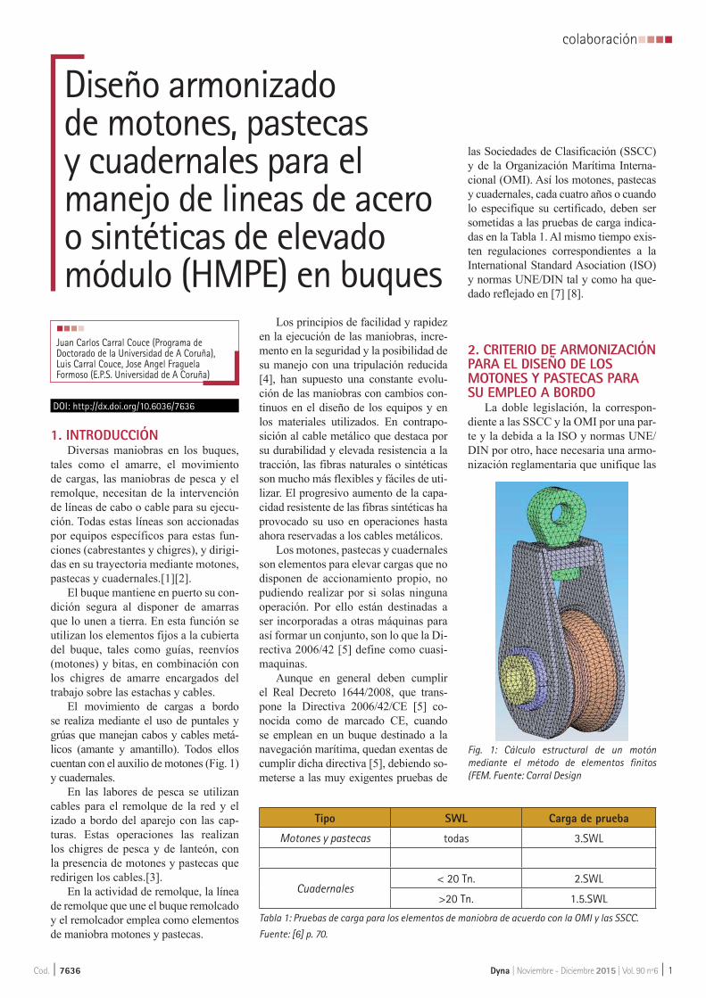
Dyna | Noviembre - Diciembre 2015 | Vol. 90 nº6 | 1
colaboraciónnnnn
Cod. | 7636
1. INTRODUCCIÓNDiversas maniobras en los buques,
tales como el amarre, el movimiento de cargas, las maniobras de pesca y el remolque, necesitan de la intervención de líneas de cabo o cable para su ejecu-ción. Todas estas líneas son accionadas por equipos específicos para estas fun-ciones (cabrestantes y chigres), y dirigi-das en su trayectoria mediante motones, pastecas y cuadernales.[1][2].
El buque mantiene en puerto su con-dición segura al disponer de amarras que lo unen a tierra. En esta función se utilizan los elementos fijos a la cubierta del buque, tales como guías, reenvíos (motones) y bitas, en combinación con los chigres de amarre encargados del trabajo sobre las estachas y cables.
El movimiento de cargas a bordo se realiza mediante el uso de puntales y grúas que manejan cabos y cables metá-licos (amante y amantillo). Todos ellos cuentan con el auxilio de motones (Fig. 1) y cuadernales.
En las labores de pesca se utilizan cables para el remolque de la red y el izado a bordo del aparejo con las cap-turas. Estas operaciones las realizan los chigres de pesca y de lanteón, con la presencia de motones y pastecas que redirigen los cables.[3].
En la actividad de remolque, la línea de remolque que une el buque remolcado y el remolcador emplea como elementos de maniobra motones y pastecas.
Los principios de facilidad y rapidez en la ejecución de las maniobras, incre-mento en la seguridad y la posibilidad de su manejo con una tripulación reducida [4], han supuesto una constante evolu-ción de las maniobras con cambios con-tinuos en el diseño de los equipos y en los materiales utilizados. En contrapo-sición al cable metálico que destaca por su durabilidad y elevada resistencia a la tracción, las fibras naturales o sintéticas son mucho más flexibles y fáciles de uti-lizar. El progresivo aumento de la capa-cidad resistente de las fibras sintéticas ha provocado su uso en operaciones hasta ahora reservadas a los cables metálicos.
Los motones, pastecas y cuadernales son elementos para elevar cargas que no disponen de accionamiento propio, no pudiendo realizar por si solas ninguna operación. Por ello están destinadas a ser incorporadas a otras máquinas para así formar un conjunto, son lo que la Di-rectiva 2006/42 [5] define como cuasi-maquinas.
Aunque en general deben cumplir el Real Decreto 1644/2008, que trans-pone la Directiva 2006/42/CE [5] co-nocida como de marcado CE, cuando se emplean en un buque destinado a la navegación marítima, quedan exentas de cumplir dicha directiva [5], debiendo so-meterse a las muy exigentes pruebas de
las Sociedades de Clasificación (SSCC) y de la Organización Marítima Interna-cional (OMI). Así los motones, pastecas y cuadernales, cada cuatro años o cuando lo especifique su certificado, deben ser sometidas a las pruebas de carga indica-das en la Tabla 1. Al mismo tiempo exis-ten regulaciones correspondientes a la International Standard Asociation (ISO) y normas UNE/DIN tal y como ha que-dado reflejado en [7] [8].
2. CRITERIO DE ARMONIZACIÓN PARA EL DISEÑO DE LOS MOTONES Y PASTECAS PARA SU EMPLEO A BORDO
La doble legislación, la correspon-diente a las SSCC y la OMI por una par-te y la debida a la ISO y normas UNE/DIN por otro, hace necesaria una armo-nización reglamentaria que unifique las
Diseño armonizado de motones, pastecas y cuadernales para el manejo de lineas de acero o sintéticas de elevado módulo (HMPE) en buquesnnnn
Juan Carlos Carral Couce (Programa de Doctorado de la Universidad de A Coruña), Luis Carral Couce, Jose Angel Fraguela Formoso (E.P.S. Universidad de A Coruña)
DOI: http://dx.doi.org/10.6036/7636
Tabla 1: Pruebas de carga para los elementos de maniobra de acuerdo con la OMI y las SSCC.
Fuente: [6] p. 70.
Tipo SWL Carga de prueba
Motones y pastecas todas 3.SWL
Cuadernales< 20 Tn. 2.SWL
>20 Tn. 1.5.SWL
Fig. 1: Cálculo estructural de un motón mediante el método de elementos finitos (FEM. Fuente: Carral Design

nnnncolaboración
2 | Dyna | Noviembre - Diciembre 2015 | Vol. 90 nº6 Cod. | 7636
exigencias facilitando la producción y comercialización de los equipos mari-nos de cubierta [7][8][9], y en particular los motones, pastecas y cuadernales en el espacio económico europeo.
2.1. CRITERIOS DE ARMONIZACIÓNDebido a razones económicas y téc-
nicas e impulsadas por las nuevas tec-nologías, las normas armonizadas son
un instrumento esencial en la Unión Europea, para eliminar los obstáculos técnicos en el mercado interior, permi-tiendo evaluar la conformidad de los productos (sistemas de acreditación, certificación, ensayos y calibraciones). Por eso, cada vez más, el Comité Eu-ropeo de Normalización, incorpora nor-mas ISO como normas EN–ISO, en el ámbito de la construcción naval de bu-
ques, embarcaciones de recreo, equipos y máquinas [8].
Aplicando esta normalización se plantea una propuesta armonizadora en-tre las reglamentaciones de diseño que consiste en conjugar los criterios de las normas ISO 4301[10] y UNE 58-112-91[11], con la norma DIN 15020[12].
2.2. CRITERIOS DE DISEÑOPor tratarse de un elemento de ele-
vación donde su uso incorrecto puede causar graves daños materiales y huma-nos, así como la existencia de efectos dinámicos que multiplican la fuerza que el cable ejerce sobre el motón, debemos ser especialmente rigurosos en los pro-cesos de diseño y de selección del equi-po más adecuado a cada tipo de aplica-ción (Fig. 2)
2.2.1. Definición del CableEl primer paso será definir el tipo
y diámetro del cable. Para ello necesi-tamos la tracción máxima en el cable que calculamos según DIN 15020[12], considerando las fuerzas de aceleración (F
a) y el rendimiento del aparejo que
esta norma propone.
(1)
a) Diámetro. Existen dos opciones:
1ª- Considerar [12], aplicando:
(2)
Donde c depende de la clasificación según [12] del grupo de mecanismo, del tipo de transporte y de la resistencia y tipo de alambres constituyentes del ca-ble, considerando 9 grupos de “1Am hasta 5m” (Tabla 2).Fig.2: Procesos de diseño y selección de un motón
Tabla 2: Clasificación del equipo de elevacióny factor de carga según [10] y [12]. Fuente: propia
Estado de Carga Vida prevista de Funcionamiento (Horas)Factor K (tipo de carga) Servicio 800 1600 3200 6400 12500
0.125 Frecuencia muy reducida de la carga máximaM31Bm
M41Am
M52m
0.250 Frecuencia reducida de la carga máximaM31Bm
M42m
M53m
M64m
0.500Frecuencia aproximadamente igual de cargas pequeñas, medianas y máximas
M31Bm
M41Am
M52m
M63m
M74m
1 Frecuencia elevada de la carga máximaM41Am
M52m
M63m
M74m
M85m

Dyna | Noviembre - Diciembre 2015 | Vol. 90 nº6 | 3
colaboraciónnnnn
Cod. | 7636
2ª- Aplicar las normas ISO 4301[10] y UNE 58-112-91[11], que fijan el valor mínimo del coeficiente de seguridad Z
p
del cable frente a la rotura;
(3)
El valor de la seguridad mínima Zp
depende de la clasificación según ISO 4301[10] del grupo de mecanismo y del tipo de carga (K), considerando 8 grupos-de “M1 a M8” (Tabla 2). Los coeficientes “c” y “Z
p”, se indican en la Tabla 3.
b) Tipo de cable. Depende de la apli-cación tal y como recoge [13].
2.2.2. Definición del Motón2.2.2.1. Criterio Funcional a) Número de Poleas. El siste-
ma de maniobra vendrá determinado por la desmultiplicación, o número de poleas(n), necesarias para elevar la car-ga con el tiro disponible. Su cálculo se hace considerando el rendimiento de los aparejos indicado en (12) (ver tabla 4) y aplicando
(4)
b) Dimensiones de las poleas. Las poleas quedan definidas por el diámetro
primitivo y el radio de la garganta. Aun-que ambos parámetros son proporcio-nales al diámetro del cable, las normas [10] y [12] consideran diferentes coefi-cientes de proporcionalidad.
Para el diámetro [12] emplea la ex-presión (5), considerando el grupo de elevación y el tipo de montaje (Tablas 5 y 6), y [10] emplea la expresión (6) que solo considera el grupo de elevación.
(5)
(6)
En poleas, donde el ángulo abrazado por el cable en la polea (θ) es siempre menor de 360º, se podrá aplicar la fór-mula que indica [13].
(7)
Siendo g:
(8)
La Tabla 7 resume los valores de D´/d, según [13] para cargas medias y máximas (correspondientes a los valo-res de K=0,5 y K=1 en la tabla 2) para las condiciones habituales de motones y pastecas (cables de cordones corrientes y un ángulo abrazado de 120º).
El perfil de la garganta resulta deter-minante para la duración del cable y la polea. Para que el cable no se aplaste ni
Tabla 3: Comparativa de los coeficientes de cálculo: c para [12] y Zp para [10].
Fuente: propia
ISO 4301[10] DIN 15020[12]
GrupoSeguridad Zp
GrupoCoeficiente c
Normal Cargas peligrosasNormal Cargas peligrosas
180 200 180 200
M3 3,5 4 1Bm 0,250 0,235 0,265 0,250
M4 4 4,5 1Am 0,265 0,250 0,280 0,265
M5 4.5 5,6 2m 0,280 0,265 0,315 0,280
M6 5,6 7,1 3m 0,315 0,280 0,335 0,325
M7 7,1 9 4m 0,335 0,325 0,375 0,365
M8 9 11,2 5m 0,375 0,365 0,425 0,400
Nº poleas (n) 2 3 4 5 6 7 8 9
Cojinetes 0,98 0,96 0,94 0,92 0,91 0,89 0,87 0,85
Rodamientos 0,99 0,98 0,97 0,96 0,95 0,94 0,93 0,92
Tabla 4: Valores del rendimiento ) de los aparejos según ISO 15020[12].
Fuente: propia
Grupo h 1Cable normal h 1Cable antigiratorio
FEM DIN Poleacable
Polea compens. Polea cable Polea
compens.M1 1 Dm 12,5 10 14 12,5M2 1 Cm 14 12,5 16 14M3 1 Bm 16 12,5 18 14M4 1 Am 18 14 20 16M5 2 m 20 14 22,4 16M6 3 m 22,4 16 25 18M7 4 m 25 16 28 18M8 5 m 28 18 31,5 20
Tabla 5: Valores del coeficiente h 1, extracto de [12] y [10].
Fuente: propia

nnnncolaboración
4 | Dyna | Noviembre - Diciembre 2015 | Vol. 90 nº6 Cod. | 7636
se pellizque [12] solamente recomienda un radio de garganta r
1 igual a 0,525 ve-
ces el diámetro del cable, mientras que [14], es mucho más explícito, y admi-tiendo una desviación máxima del cable de 4º, tabula el radio de la garganta, su altura y el espesor de las pestañas para cada diámetro de cable. También indica que para evitar presiones excesivas del cable sobre la polea, este debe reposar sobre un arco de círculo mayor de 45º.
Referencias basadas en la experien-cia, como [15] y [16], incluyen tablas donde para aumentar la vida del cable
proponen gargantas más amplias que la normativa [14].
Referencias como [15] y [17] aña-den que para trabajos intensivos se de-berá templar el área de contacto de la
polea hasta alcanzar una dureza mínima entre 200 y 230 Brinell según [15],y de 35 Rockwell C según [17].
c) Sistema de suspensión. De igual modo será necesario definir la geome-tría del elemento que une el motón a un punto fijo: el sistema de suspensión. Su objetivo es limitar el ángulo de desvia-ción del cable con la polea, a valores próximos a cero. Así [17] admite un ángulo máximo de desviación del cable de 1,5º, mientras que [10] y [14] admi-ten hasta 4º para cables normales y 1,5º para cables antigiratorios.
2.2.2.2. Criterio de capacidad re-sistente
Los criterios para definir la capa-cidad resistente de los mecanismos de elevación figuran en la normas FEM 1001/98 [18] “Cálculo de los aparatos de elevación”, y UNE-EN 13001-2 [19] “Seguridad de las grúas”. Ambas, [18][19] garantizan la seguridad definiendo unos estados de cargas mayorados, pero mientras que [18] lo hace en función del tipo de elemento de elevación (clase de grúa) y del tipo de mecanismo (eleva-ción, desplazamiento, rotación, etc.), [19] lo hace en función del tipo de carga considerada (normal, ocasional, excep-cional).
Grupo h 2 Descripción
FEM 1 En todos los casos
DIN2 Polea de cable con doblez en el mismo sentido4 Polea de cable con doblez en sentido contrario0 Polea de compensación. Polea de equilibrio
Tabla 6: Valores del coeficiente h 2, extracto de [12] y [10].
Fuente: propia
Tipo de cable
Relación D´/d
Uso esporádico Uso habitual Uso intensivo
Cargas medias
Cargas máximas
Cargas medias
Cargas máximas
Cargas medias
Cargas máximas
6 x 7 + 1 11 12 13 14 15 16
6 x 19 + 1 10 11 11 12 13 14
6 x 27 +1 9 10 10 11 12 13
6 x 37 +1 9 9 9 10 11 12
Tabla 7: Relación entre el diámetro de la polea y el del cable.
Fuente: propia a partir de[13]
Fig. 3: Perfil garganta según DIN 15061 [14].
Fuente: propia
Radio garganta r1 h I md cable (mm)
[14] [16] [14] [16] [14] [16] [14] [16]
4,2 4,8 15 18 18 20 4 5 8
6,5 7,2 20 25 25 30 5 5 12
9,5 10,2 30 32 38 40 6 8 18
13 13,2 37,5 40 48 50 8 10 24
16 16,8 45 48 59 60 8 11 30
21 21,8 60 64 78 85 11 15 40
28 28.4 75 75 99 100 12,5 17,5 52
Tabla 8: Comparativa dimensiones de la garganta.
Fuente: propia en base a [14] y[16]
Tabla 9: Coeficientes de mayoración según FEM 1001/98.
Fuente: [18]
Elemento de elevación M1 M2 M3 M4 M5 M6 M7 M8
Coefte. γm-FactorKu 1,00 1,04 1,08 1,12 1,16 1,20 1,25 1,30
Tipo de mecanismo A1 A2 A3 A4 A5 A6 A7 A8
Coefte. γc- FactorKu 1,00 1,02 1,05 1,08 1,11 1,14 1,17 1,20
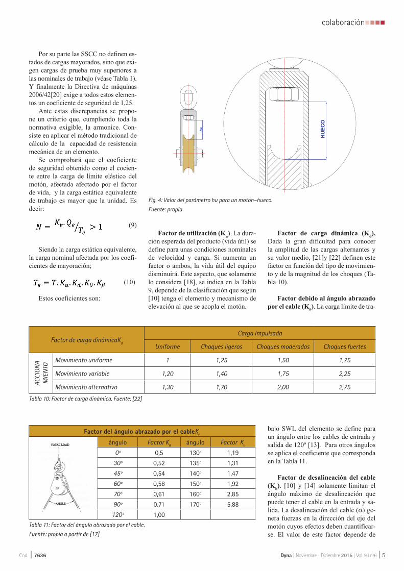
Dyna | Noviembre - Diciembre 2015 | Vol. 90 nº6 | 5
colaboraciónnnnn
Cod. | 7636
Por su parte las SSCC no definen es-tados de cargas mayorados, sino que exi-gen cargas de prueba muy superiores a las nominales de trabajo (véase Tabla 1). Y finalmente la Directiva de máquinas 2006/42[20] exige a todos estos elemen-tos un coeficiente de seguridad de 1,25.
Ante estas discrepancias se propo-ne un criterio que, cumpliendo toda la normativa exigible, la armonice. Con-siste en aplicar el método tradicional de cálculo de la capacidad de resistencia mecánica de un elemento.
Se comprobará que el coeficiente de seguridad obtenido como el cocien-te entre la carga de límite elástico del motón, afectada afectado por el factor de vida, y la carga estática equivalente de trabajo es mayor que la unidad. Es decir:
(9)
Siendo la carga estática equivalente, la carga nominal afectada por los coefi-cientes de mayoración;
(10)
Estos coeficientes son:
Factor de utilización (Ku). La dura-ción esperada del producto (vida útil) se define para unas condiciones nominales de velocidad y carga. Si aumenta un factor o ambos, la vida útil del equipo disminuirá. Este aspecto, que solamente lo considera [18], se indica en la Tabla 9, depende de la clasificación que según [10] tenga el elemento y mecanismo de elevación al que se acopla el motón.
Factor de carga dinámica (Kd), Dada la gran dificultad para conocer la amplitud de las cargas alternantes y su valor medio, [21]y [22] definen este factor en función del tipo de movimien-to y de la magnitud de los choques (Ta-bla 10).
Factor debido al ángulo abrazado por el cable (K
θ). La carga límite de tra-
bajo SWL del elemento se define para un ángulo entre los cables de entrada y salida de 120º [13]. Para otros ángulos se aplica el coeficiente que corresponda en la Tabla 11.
Factor de desalineación del cable (Kb). [10] y [14] solamente limitan el ángulo máximo de desalineación que puede tener el cable en la entrada y sa-lida. La desalineación del cable (α) ge-nera fuerzas en la dirección del eje del motón cuyos efectos deben cuantificar-se. El valor de este factor depende de
Factor de carga dinámicaKd
Carga Impulsada
Uniforme Choques ligeros Choques moderados Choques fuertes
ACCI
ONA
MIE
NTO
Movimiento uniforme 1 1,25 1,50 1,75
Movimiento variable 1,20 1,40 1,75 2,25
Movimiento alternativo 1,30 1,70 2,00 2,75
Tabla 10: Factor de carga dinámica. Fuente: [22]
Factor del ángulo abrazado por el cableKθ
ángulo Factor Kθ ángulo Factor K
θ
0º 0,5 130º 1,19
30º 0,52 135º 1,31
45º 0,54 140º 1,47
60º 0,58 150º 1,92
70º 0,61 160º 2,85
90º 0.71 170º 5,88
120º 1,00
Tabla 11: Factor del ángulo abrazado por el cable.
Fuente: propia a partir de [17]
Fig. 4: Valor del parámetro hu para un motón–hueco.
Fuente: propia

nnnncolaboración
6 | Dyna | Noviembre - Diciembre 2015 | Vol. 90 nº6 Cod. | 7636
la geometría del motón y del ángulo de inclinación del cable respondiendo a la fórmula.
(11)
Para motones con geometría norma-lizadas según [23], y aceptando como admisible el ángulo desalineación de 2º considerado por [10] y [14], se obtienen los valores que se recogen en la Tabla 12.
Otros elementos que podrían com-probarse son los rodamientos. Para ello se pueden aplicar las directrices de la norma ISO -281/I-77[24] consideran-do la vida prevista del equipo aceptada para clasificar el equipo de elevación.
2.3. PROPUESTA ARMONIZADORALa Tabla 13 recoge un resumen de
las propuestas que se han enunciado para el diseño de motones y pastecas.
3. ADAPTACIÓN DE LA POLEA AL USO DE LÍNEAS HMPE (HIGH MODULUS POLYETHYLENE FIBRE)
Buscando una mayor eficacia en las maniobras de amarre, líneas de remol-que, grúas y manejo de cargas, en los últimos años la industria marítima se ha dirigido hacia el empleo de la fibra arti-ficial denominada HMPE (High Modu-lusPolyethyleneFibre) [25] P. 127. Sus grandes ventajas frente a otros materia-les (Tabla 14); resistencia comprable a la del acero, mejor relación resistencia/peso que las demás fibras manteniendo un peso específico inferior a 1, lo que evita enredos con la hélice a la vez que
facilita el cobrado de la línea en el caso de remolcadores [26], han conducido a su rápida aceptación.
Las modificaciones a introducir en el proceso de diseño serán la conse-cuencia de la búsqueda del acabado su-perficial que minimice la perdida de las propiedades mecánicas del material y la optimización de las dimensiones de la polea, así como la de seguir la tendencia actual en la búsqueda de materiales más resistentes a la intemperie.
Acabado superficialEl empleo generalizado en las ma-
niobras de remolque de chigres de ten-sión constante donde el equipo repeti-
Angulo 1º 2º 3º 4º 5º
Factor de desalineación Kb 0,65 1,0 1,34 1,69 2,04
Tabla 12: Factor de desalineación del cable. Fuente: propia
Criterio Parámetro Criterio armonizado en base a la referencia Indicaciones
Funcional
Nº de poleas DIN 15020[12]
Diámetro polea MartínezIbárruri[13]Considera el ángulo abrazado por el cable en la
polea, lo que no hacen las normas DIN 15020[12] e ISO 4301 FEM [10]
Perfil garganta Larrode et al.[16] Garganta más ancha que la norma DIN 15061[14]
Sistema de suspensión Elaboración propiaYa que únicamente existe normativa que limita la
inclinación del cable
Resistente
Factor de utilización FEM 1001/98[18] Clasificación según ISO 4301 [10] y DIN 15020[12]
Factor de carga dinámicaDudley [21]
y Mott [22]
La normativa actual no considera los factores dinámicos
Factor de ángulo abrazado Crosby Group. [17] No lo contempla la FEM 1001[18]
Factor de desalineación Elaboración propia Existencia de normativa que limita su valor máximo
Tabla 13: Resumen de la propuesta armonizadora. Fuente: propia
Tabla 14: Comparativa entre las propiedades de líneas de 72 mm. de diversos materiales. Fuente: Propia
MaterialDiámetro (mm)
Peso (kg/100m)
MBL (kN)Alargamiento al 40 % del MBL
Alargamiento al 100% del MBL
Peso específico
Punto de fusión (ºC)
Coeficinte dinámico de fricción contra el metal
Polyester “double braid”
72 447.9 1054 8.5% 15-20% 1.38 250 0.12-0.15
Acero 72 2200 3500 0.8% 2-3% 7.85 1600 0.23
HMPE 72 318.5 3470 1.5% 4-5% 0.97 140 0.07

Dyna | Noviembre - Diciembre 2015 | Vol. 90 nº6 | 7
colaboraciónnnnn
Cod. | 7636
tivamente cobra y larga línea, provoca un giro alternativo de las poleas. Este giro se traduce en un calentamiento de la línea debido, por lo menos a tres fac-tores [27]: roce interno entre fibras por la tracción, roce interno por el giro de las fibras al curvarse en la polea y roce externo de la línea sobre la polea. Estos efectos son proporcionales a la frecuen-cia del giro y al tiro en la línea.
La consideración de la norma [14], para determinar la garganta de las po-leas trabajando con cable de modo con-tinuo, recomienda una rugosidad de 5 micras. La OCIMF[25] P. 166, a la hora de considerar los dispositivos de ama-rre, en el caso concreto de los alavantes determina un acabado que conduzca a una rugosidad media de 10 micras. En cuanto a las líneas de remolque, la ref. [29] (Figura 6) indica el efecto que la variación en la rugosidad de la bita (sta-ple) presenta sobre la disminución de la resistencia al cabo de 5000 ciclos de abrasión, y recomienda un acabado su-perficial de 8 micras para los accesorios dispuestos en cubierta que entren en contacto con la línea.
La norma [14], para trabajos en con-tinuo recomienda una rugosidad en la garganta de las poleas de 5 micras. La OCIMF [25] P. 166, a la hora de con-siderar los dispositivos de amarre, en el caso concreto de los alavantes, determi-na un acabado que conduzca a una rugo-sidad media de 10 micras.
Considerando que actualmente es relativamente sencillo conseguir aca-
bados superficiales Ra de 3,2 μm., este sería el valor máximo aconsejado para la garganta de las poleas.
Dimensiones de las poleasPara las fibras artificiales [30] de-
termina un diámetro de la polea igual a 10 veces el diámetro de la línea con trenzado plaited, y de 8 veces para el trenzado braided. Para su arrollamien-to en carreteles la norma EN ISO 3730 [31]. “Shipbuilding – Mooringwinches” determina un valor mínimo de 6 veces el diámetro de la estacha. Si considera-mos el diámetro necesario para la cir-culación de la estacha alrededor de un reenvío, la OCIMF [25] P. 82 establece una relación de 8.
Inalterabilidad de su acabado su-perficial
Considerando la agresividad del ambiente externo, y mientras no aparez-can nuevos materiales, para garantizar el mantenimiento de la rugosidad de la garganta la mejor solución actual es el empleo de aleaciones del tipo acero inoxidable [32] P. 150.
Otros elementosDebido a la mayor flexibilidad de
las de líneas HMPE, el ángulo de incli-nación de la línea en la polea será mu-cho menos crítico. Diferente es el caso de los rodamientos y del eje de la polea que al aumentar su número de ciclos de trabajo se deben dimensionar para esta nueva eventualidad.
CONCLUSIONESLos motones, pastecas y cuaderna-
les son elementos auxiliares fundamen-tales en los buques para la realización de maniobras, sin embargo su consi-deración como elementos auxiliares, hace que su tratamiento regulatorio se encuentre disperso en una variada nor-mativa. Con el desarrollo tecnológico de las líneas sintéticas de elevado mó-dulo HMPE, que progresivamente van sustituyendo a los cables de acero, la normativa basada en ese material ha quedado obsoleta.
Del análisis de la normativa existen-te se deduce la necesidad de contar con una regulación completa y adecuada a las circunstancias de su uso a bordo. La propuesta de armonización recogida en la Tabla 13 considera los requisitos fun-damentales que debe cumplir todo equi-po; funcionales y resistentes.
Para los requisitos funcionales, las normas aplican diferentes criterios para las dimensiones de las poleas. Por ello se hace necesario formular una propues-ta para determinar su diámetro y anchu-ra, de acuerdo a normas más acordes con la operativa marítima. En relación con el tipo de suspensión, se establecen las limitaciones en el ángulo del cable por encima del cual deberá permitirse la libre orientación de la polea.
Los requisitos resistentes son el as-pecto que presenta una mayor necesidad de criterios regulatorios. Se propone seguir el método clásico de capacidad resistente mayorando las cargas y consi-
Fig. 6: Variación de la resistencia residual de la línea al variar la rugosidad de la guía.
Fuente: [29]Fig. 5: Línea de HPME deslizando en la garganta de un motón. Fuente [28]
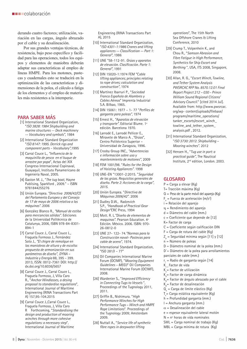
nnnncolaboración
8 | Dyna | Noviembre - Diciembre 2015 | Vol. 90 nº6 Cod. | 7636
derando cuatro factores; utilización, va-riación en las cargas, ángulo abrazado por el cable y su desalineación.
Por sus grandes ventajas técnicas, de resistencia, bajo peso específico y facili-dad para las operaciones, todos los equi-pos y elementos de maniobra deberán adaptar sus características al empleo de líneas HMPE. Para los motones, paste-cas y cuadernales esto se traducirá en la optimización de las características y di-mensiones de la polea, el cálculo a fatiga de los elementos y el empleo de materia-les más resistentes a la intemperie.
PARA SABER MÁS[1] International Standard Organization,
“ISO 3828: 1984 Shipbuilding and marine structures -- Deck machinery -- Vocabulary and symbols”, 1984
[2] International Standard Organization “ISO 8147: 1995. Derrick rigs and component parts – Vocabulary”,1995
[3] Carral Couce L., “Influencia de la maquinilla de pesca en el buque de arrastre por popa”, Actas del XIX Congreso Internacional Copinaval, Guayaquil, Instituto Panamericano de Ingeniería Naval, 2005.
[4] Gaston M. J., “The tug boat, Hayne Publising, Sparkford , 2009.” – ISBN 9781844255276
[5] Unión Europea. “Directiva 2006/42/CE del Parlamento Europeo y del Consejo de 17 de mayo de 2006 relativa a las máquinas”. 2006
[6] González Blanco R., “Manual de estiba para mercancías sólidas”. Ediciones de la Universidad Politécnica de Catalunya, 2006, ISBN 978-84-8301-894-1
[7] Carral Couce J., Carral Couce L., Fraguela Formoso J., Fernández Soto J., “El chigre de remolque en las maniobras de altura y de escolta: propuesta de armonización en sus parámetros de diseño”, DYNA – Industria y Energía 88, 395 - 399. 2013, ISSN: 0012-7361 DOI: http://dx.doi.org/10.6036/5657
[8] Carral Couce J., Carral Couce L., Fraguela Formoso, J, Villa Caro R., “Anchor Windlasses, a desing proposal to standardise regulations”, International Journal of Maritime Engineering (RINA Transactions Part A) 157,95-104.2015
[9] Carral Couce J.,Carral Couce L., Fraguela Formoso, J, Villa Caro R Forthcoming, “Standardising the design and production of mooring winches through more cohesive regulations: a necessary step”, International Journal of Maritime
Engineering (RINA Transactions Part A), 2015
[10] International Standard Organization, “ISO 4301-1:1986 Cranes and lifting appliances -- Classification -- Part 1: General”, 1986
[11] UNE “58-112-91. Grúas y aparatos de elevación. Clasificación. Parte 1: General”, 1991
[12] DIN 15020-1:1974 FEM “Cable lifting appliances; principles relating to rope drives; calculation and construction”, 1974
[13] Martínez Ibarruri P., “Sociedad Franco Española de Alambres y Cables Aéreos” Imprenta Industrial S.A. Bilbao, 1965.
[14] DIN 15061: 1977 – 1- 77 “Perfiles de garganta para poleas”, 1974
[15] Ernest H., “Aparatos de elevación y transporte”. Editorial Blume. 1ª edición. Barcelona 1970.
[16] Larrodé E., Larrodé Pellicer E., Miravete de Marco A. ,“Grúas”, Centro Politécnico Superior – Universidad de Zaragoza, 1996.
[17] Crosby Group INC., “Advertencias e información sobre uso y mantenimiento de motones”, 2009
[18] FEM 1001/98. “Rules for the Design of Hoisting Appliances”. 1998
[19] UNE-EN “13001-2:2015. ”Seguridad de las grúas. Requisitos generales de diseño. Parte 2: Acciones de la carga”, 2015.
[20] Unión Europea. “Directiva de Máquinas 2006/42”. 2006
[21] Dudley D.W., Radzevich S.P., “Handbook of Practical Gear Design”CRC Press, 1994
[22] Mott. R. L.”Diseño de elementos de maquinas”. Pearson Education. 4ª Edición. México. 2006. ISBN: 970-26-0812-0
[23] UNE 27- 122- 74.“Normas para la Construcción naval- Pastecas para cable de acero”, 1974.
[24] International Standard Organization, “ISO 281/I – 77”
[25] Oil Companies International Marine Forum (OCIMF), “Mooring Equipment Guidelines – MEG3” Oil Companies International Marine Forum (OCIMF), 2008.
[26] Wardenier S., “Improved Efficiency in Connecting Tugs to Vessels “, Proceedings of the Tugnology 2011, 2011.
[27] Griffin B., Nishimura. “High Performance Winches for High Performance Tugs – Winch and HMPE Rope Limitations”. Proceedings of the Tugnology 2009; Amsterdam 2009.
[28] Nuttall A., “Service life of synthetic fibre ropes in deepwater lifting
operations”, The 15th North Sea Offshore Cranes & Lifting Conference, 2010
[29] Crump T., Volpenhein K., and Chou R., “Samson Abrasion and Fibre Fatigue in High Performance, Synthetics for Ship Escort and Berthing “, USA, ITS 2008, Singapore, 2008.
[30] Allan, R. G., “Escort Winch, Towline, and Tether System Analysis PWSRCAC RFP No. 8570.12.01 Final Report Project 212 – 030 - Prince William Sound Regional Citizens’ Advisory Council.” [cited 2014 Jul]. Available from: http://www.pwsrcac.org/wp- content/uploads/filebase/programs/maritime_operations/tanker_escorts/escort_winch_towline_and_tether_system_analysis.pdf , 2012.
[31] International Standard Organization, “ISO 3730: 2012. Shipbuilding – Mooring winches”. 2012
[32] Hensen H., “Tug use in port: a practical guide”, The Nautical Institute, 2nd edition, London. 2003.
GLOSARIOP = Carga a elevar (Kg)T= Tracción máxima (Kg)Q = Peso de la parte móvil del aparejo (Kg) Fa = Fuerza de aceleración (m/s2)i = Relación del aparejoη = Rendimiento del aparejod = Diámetro del cable (mm.)c = Coeficiente que depende de [12]K= Factor de cargaC = Coeficiente según calificación DINF = Carga de rotura del cable (Kg)Zp = Seguridad mínima según [11] y [12]n = Número de poleasD = Diámetro nominal de la polea (mm.)D´= Diámetro de la polea para arrollamientos parciales de cable (mm.)r1 = Radio de garganta según [14]Kv = Factor de vidaKu= Factor de utilizaciónKd= Factor de carga dinámicaKθ= Factor de ángulo abrazado por el cable
Kβ= Factor de desalineación
Qe = Carga de límite elástico (Kg)Te= Carga estática equivalente (Kg)h = Profundidad garganta (mm.)I = Anchura garganta (mm.) α = Desalineación del cable e = espesor equivalente lateral motónN = nº horas de vida nominalesSWL = Carga nominal de trabajo (Kg)MBL = Carga mínima de rotura (Kg)

Diseño de maquinaria de cubierta de buques, en base a una propuesta razonada de armonización reglamentaria Pág. 83
5.5. EL CHIGRE DE REMOLQUE EN LAS
MANIOBRAS DE ALTURA Y DE ESCOLTA:
PROPUESTA DE ARMONIZACIÓN EN SUS
PARÁMETROS DE DISEÑO
Juan Carlos Carral-Couce. Luis Carral-Couce. José Ángel Fraguela-Formoso. José Luis Fernández-Soto Dyna, ISSN 0012-7361, Cod 5657 Julio Agosto 2013. Vol. 88, Nº 4, 2013, págs. 395-399 DOI: http://dx.doi.org/10.6036/5657

Diseño de maquinaria de cubierta de buques, en base a una propuesta razonada de armonización reglamentaria Pág. 84
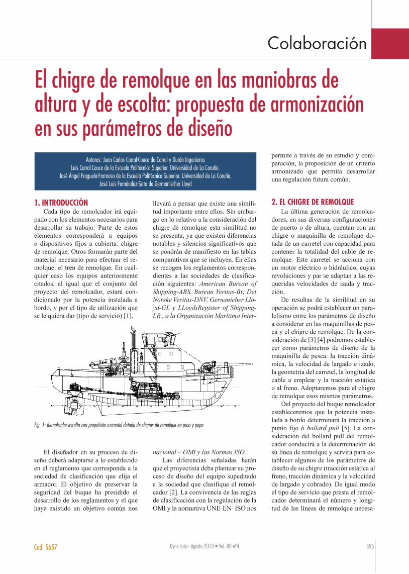
Colaboración
Dyna Julio - Agosto 2013 • Vol. 88 nº4 395Cod. 5657
1. INTRODUCCIÓNCada tipo de remolcador irá equi-
pado con los elementos necesarios para desarrollar su trabajo. Parte de estos elementos corresponderá a equipos o dispositivos fijos a cubierta: chigre de remolque. Otros formarán parte del material necesario para efectuar el re-molque: el tren de remolque. En cual-quier caso los equipos anteriormente citados, al igual que el conjunto del proyecto del remolcador, estará con-dicionado por la potencia instalada a bordo, y por el tipo de utilización que se le quiera dar (tipo de servicio) [1].
El diseñador en su proceso de di-seño deberá adaptarse a lo establecido en el reglamento que corresponda a la sociedad de clasificación que elija el armador. El objetivo de preservar la seguridad del buque ha presidido el desarrollo de los reglamentos y el que haya existido un objetivo común nos
llevará a pensar que existe una simili-tud importante entre ellos. Sin embar-go en lo relativo a la consideración del chigre de remolque esta similitud no se presenta, ya que existen diferencias notables y silencios significativos que se pondrán de manifiesto en las tablas comparativas que se incluyen. En ellas se recogen los reglamentos correspon-dientes a las sociedades de clasifica-ción siguientes: American Bureau of Shipping-ABS, Bureau Veritas-Bv, Det Norske Veritas-DNV, Gernanicher Llo-yd-GL y LLoydsRegister of Shipping-LR., a la Organización Marítima Inter-
nacional – OMI y las Normas ISO.Las diferencias señaladas harán
que el proyectista deba plantear su pro-ceso de diseño del equipo supeditado a la sociedad que clasifique el remol-cador [2]. La convivencia de las reglas de clasificación con la regulación de la OMI y la normativa UNE-EN–ISO nos
permite a través de su estudio y com-paración, la proposición de un criterio armonizado que permita desarrollar una regulación futura común.
2. EL CHIGRE DE REMOLQUELa última generación de remolca-
dores, en sus diversas configuraciones de puerto o de altura, cuentan con un chigre o maquinilla de remolque do-tada de un carretel con capacidad para contener la totalidad del cable de re-molque. Este carretel se acciona con un motor eléctrico o hidráulico, cuyas revoluciones y par se adaptan a las re-queridas velocidades de izada y trac-ción.
De resultas de la similitud en su operación se podrá establecer un para-lelismo entre los parámetros de diseño a considerar en las maquinillas de pes-ca y el chigre de remolque. De la con-sideración de [3] [4] podremos estable-cer como parámetros de diseño de la maquinilla de pesca: la tracción diná-mica, la velocidad de largado e izado, la geometría del carretel, la longitud de cable a emplear y la tracción estática o al freno. Adoptaremos para el chigre de remolque esos mismos parámetros.
Del proyecto del buque remolcador estableceremos que la potencia insta-lada a bordo determinará la tracción a punto fijo ó bollard pull [5]. La con-sideración del bollard pull del remol-cador conducirá a la determinación de su línea de remolque y servirá para es-tablecer algunos de los parámetros de diseño de su chigre (tracción estática al freno, tracción dinámica y la velocidad de largado y cobrado). De igual modo el tipo de servicio que presta el remol-cador determinará el número y longi-tud de las líneas de remolque necesa-
El chigre de remolque en las maniobras de altura y de escolta: propuesta de armonización en sus parámetros de diseño
Autores: Juan Carlos Carral-Couce de Carral y Durán IngenierosLuis Carral-Couce de la Escuela Politécnica Superior. Universidad de La Coruña.
José Ángel Fraguela-Formoso de la Escuela Politécnica Superior. Universidad de La Coruña.José Luis Fernández-Soto de Germanischer Lloyd
Fig. 1: Remolcador escolta con propulsión azimutal dotado de chigres de remolque en proa y popa
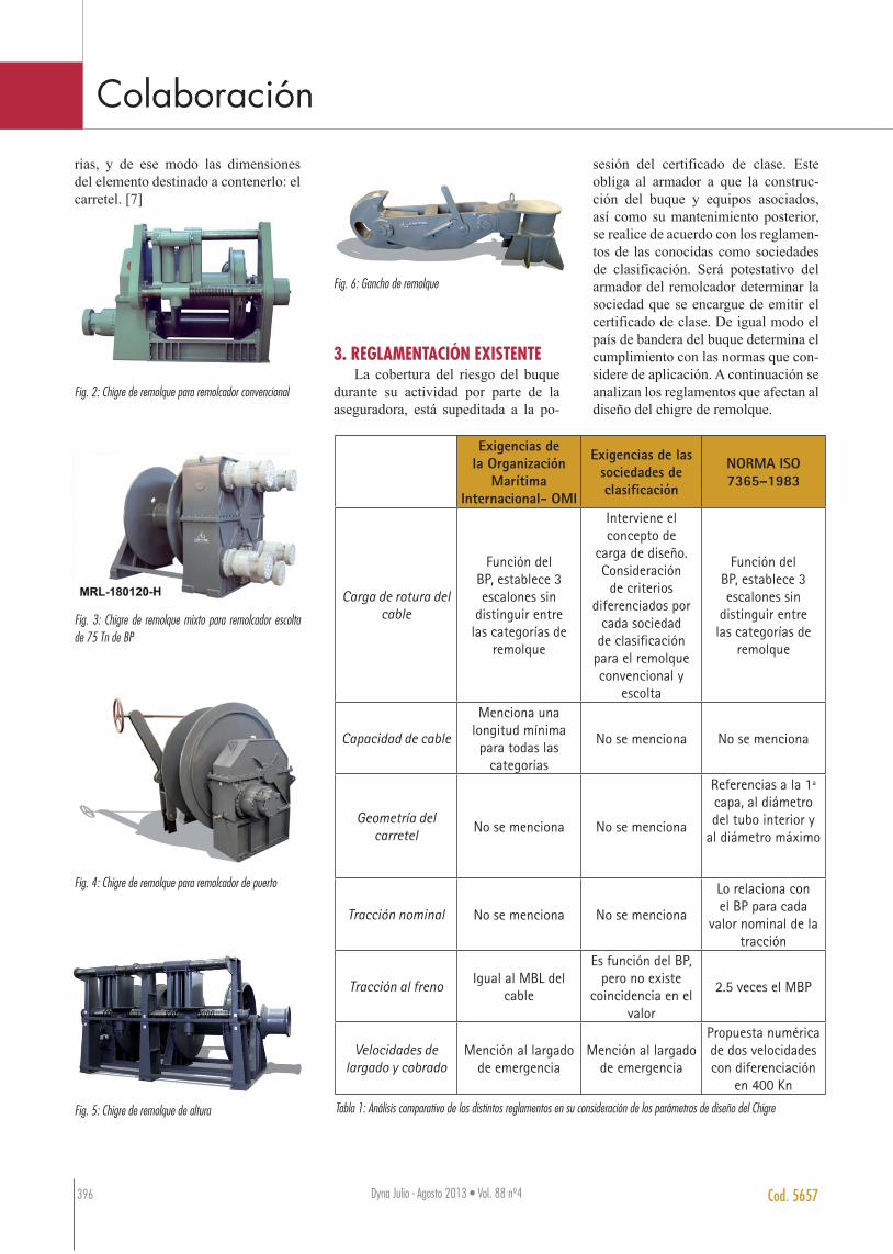
Colaboración
Dyna Julio - Agosto 2013 • Vol. 88 nº4Dyna Julio - Agosto 2013 • Vol. 88 nº4396 Cod. 5657
rias, y de ese modo las dimensiones del elemento destinado a contenerlo: el carretel. [7]
Fig. 2: Chigre de remolque para remolcador convencional
Fig. 3: Chigre de remolque mixto para remolcador escolta de 75 Tn de BP
Fig. 4: Chigre de remolque para remolcador de puerto
Fig. 5: Chigre de remolque de altura
Fig. 6: Gancho de remolque
3. REGLAMENTACIÓN EXISTENTELa cobertura del riesgo del buque
durante su actividad por parte de la aseguradora, está supeditada a la po-
sesión del certificado de clase. Este obliga al armador a que la construc-ción del buque y equipos asociados, así como su mantenimiento posterior, se realice de acuerdo con los reglamen-tos de las conocidas como sociedades de clasificación. Será potestativo del armador del remolcador determinar la sociedad que se encargue de emitir el certificado de clase. De igual modo el país de bandera del buque determina el cumplimiento con las normas que con-sidere de aplicación. A continuación se analizan los reglamentos que afectan al diseño del chigre de remolque.
Exigencias de la Organización
Marítima Internacional- OMI
Exigencias de las sociedades de clasificación
NORMA ISO 7365–1983
Carga de rotura del cable
Función del BP, establece 3 escalones sin
distinguir entre las categorías de
remolque
Interviene el concepto de
carga de diseño. Consideración
de criterios diferenciados por
cada sociedad de clasificación
para el remolque convencional y
escolta
Función del BP, establece 3 escalones sin
distinguir entre las categorías de
remolque
Capacidad de cable
Menciona una longitud mínima para todas las
categorías
No se menciona No se menciona
Geometría del carretel No se menciona No se menciona
Referencias a la 1ª capa, al diámetro del tubo interior y
al diámetro máximo
Tracción nominal No se menciona No se menciona
Lo relaciona con el BP para cada
valor nominal de la tracción
Tracción al freno Igual al MBL del cable
Es función del BP, pero no existe
coincidencia en el valor
2.5 veces el MBP
Velocidades de largado y cobrado
Mención al largado de emergencia
Mención al largado de emergencia
Propuesta numérica de dos velocidades con diferenciación
en 400 Kn
Tabla 1: Análisis comparativo de los distintos reglamentos en su consideración de los parámetros de diseño del Chigre

Colaboración
Dyna Julio - Agosto 2013 • Vol. 88 nº4 397Dyna Julio - Agosto 2013 • Vol. 88 nº4 Cod. 5657
Las Guidelines for Safe Ocean Towing [6] de la OMI, se refieren a distintos aspectos de los buques remol-cadores y su operación. En su capítulo 12, se analiza el chigre de remolque.
Siempre resultará de interés el co-nocimiento de los contenidos de los reglamentos de las sociedades de cla-sificación que determinan los compo-nentes del chigre y el tren de remolque. En esa línea resultará sorprendente, a pesar de compartir un objetivo común, el diferente tratamiento que realizan los reglamentos: bien por sus diferen-tes prescripciones o bien por el silencio que mantienen en ciertos aspectos. En [2] se ha tratado en profundidad el al-cance de cada reglamento y del análisis de cada uno de ellos se puede deducir que las indicaciones se refieren a los aspectos operacionales, y poco o nada se regula respecto a aquellos paráme-tros que nos conducen a la definición del chigre.
En relación con el diseño de la lí-nea de remolque, los reglamentos de las sociedades de clasificación deter-minan la utilización del concepto de la mínima carga de rotura (MBL) de este elemento. El MBL se calculará como una función de las cargas de di-seño (DF) intervinientes, considerando como parámetro el valor de la tracción a punto fijo (BP). Sin embargo se pro-ponen criterios diferenciados a la hora de la determinación del BP [2].
La norma ISO 7365–1983 relativa a chigres de remolque -“shipbuilding and marine structures–deck machi-nery–towing winch for deep sea use”. analizada en último lugar, es la que presta mayor atención a los parámetros de diseño del chigre.
La siguiente tabla recoge de for-ma resumida las aportaciones de los
reglamentos enunciados en lo relativo al cálculo de los parámetros de diseño.
4. PROPUESTA DE ARMONIZACIÓN REGLAMENTARIA. PROPUESTA DE CÁLCULO
4.1. PARÁMETROS DE DISEÑO DEL CHIGRE- CALCULO PREVIO DE LA CARGA DE ROTURA DEL CABLE
Conforme a lo indicado en el punto 2, los parámetros que debemos consi-derar para definir un chigre de remol-que son los siguientes: dimensiones del carretel (capacidad de cable y geome-tría del carretel); tracciones del chigre (nominal y al freno); velocidades de largado y virado. Como cálculo previo deberemos considerar el diámetro del cable de remolque a utilizar, lo que nos obliga a la consideración de un criterio para la obtención del MBL.
A pesar de la coincidencia en la dependencia del MBL respecto al BP, la Tabla 1 recoge planteamientos bien diferentes: la OMI y la norma ISO es-tablecen tres escalones para el cálculo pero sin que intervengan las categorías de remolque. Las sociedades de clasi-ficación hacen intervenir el concepto “carga de diseño” a la vez que distin-guen entre el remolque convencional y escolta. Sin embargo sus propuestas de cálculo resultan diferentes.
La propuesta armonizadora consis-tirá en adoptar el criterio de la norma ISO. Resultando la más conservadora de todas las propuestas su cumplimien-to permitirá cubrir las demás.
4.2. DIMENSIONES DEL CARRETEL
4.2.1. Capacidad de cableEn la tabla 1 se recoge la única
aportación al respeto; la de la OMI, en la que únicamente se indica una longi-tud de cable mínima y común para to-das las categorías. Como la longitud de cable a utilizar será función de las cir-cunstancias particulares de cada buque concreto, dependiendo de dos factores: de su BP y del tipo de servicio que el remolcador realice, se ha aplicado el contenido de [7] en la que se mantie-ne el acertado criterio de relacionar la longitud del cable con el tipo de ser-vicio. (en la práctica obtendremos el factor MBL contenido en la Tabla 2 para después aplicarlo particularizarlo para cada modalidad de remolque, tal y como nos propone la Tabla 3 y obtener el valor de la longitud).
Se incluyen en la Tabla 3 las cinco categorías de remolcadores definidas en [2].
4.2.2. Geometría del carretelLa geometría del carretel vendrá
definida por tres parámetros: diámetro mínimo, diámetro máximo y anchura. Una vez fijados dos de ellos, el tercero vendrá impuesto por la longitud de ca-ble a almacenar.
El diámetro mínimo depende direc-tamente del tipo y diámetro de cable o estacha a emplear. Para evitar que este elemento sufra es recomendable mante-ner una relación mínima entre el diáme-tro del cable o estacha y el diámetro del tubo sobre el que se arrolla, así para un cable de acero esta relación es de 17 [8].
TIPO DE REMOLCADOR
NÚMERO DE CARRETELES
LONG. DE CABLE (m) VALOR MÍNIMO(m)
ST 2 2000*BP/MBL 800
U 1 1800*BP/MBL 650
R1 1 1800*BP/MBL 650
R2 1 1200*BP/MBL 500
R3 1 1200*BP/MBL 500
Tabla3: Mínima capacidad de cable del carretel, según la categoría de remolque y el BP del buque
MBP (kN) CARGA MÍNIMA DE ROTURA: MBL
<300 3.5 * MBP300 - 800 2.75 * MBP
>800 2.25 * MBP
Tabla 2: Relación entre la carga de rotura del cable y el MBP

Colaboración
Dyna Julio - Agosto 2013 • Vol. 88 nº4Dyna Julio - Agosto 2013 • Vol. 88 nº4398 Cod. 5657
El diámetro máximo del carretel vendrá impuesto por la variación ad-misible entre la velocidad en primera capa y en la última. En [8] se establece la formulación adecuada para el cálcu-lo del valor del diámetro máximo es-tableciendo una restricción en el 25% de variación de la velocidad nominal, de igual modo se propone la expresión a emplear para la obtención del tercer parámetro: la longitud del carretel. Re-cordar que la norma ISO establece una holgura entre la última capa y el exte-rior del carretel de al menos 1,5 veces el diámetro del cable. La fórmula de [8] ha sido modificada para tener en cuenta este último extremo.
(1)
Siendo: dcable
= diámetro del cable (mm); C
cable = capacidad de cable (m);
Dmax
= diámetro máximo del carretel (mm); d
min = diámetro mínimo del ca-
rretel (mm); kest
= coeficiente de estiba
4.3. TRACCIÓN DEL CHIGRE
4.3.1. Tracción nominalNada se considera al respeto en
los reglamentos estudiados, excepción hecha de la norma ISO. En esta se en-cuentran tabulados diversos valores de tracción y su correspondencia con un BP propuesto. Sin embargo, la prácti-ca nos indica que el proceso de cálculo a seguir es precisamente el contrario: se parte del BP del remolcador y en el astillero se determina la tracción no-minal del chigre. De esta experiencia, y contando con la base de datos pro-porcionada por las recientes entregas de buques remolcadores producidas en astilleros españoles, se ha obtenido la Tabla 4 que recoge la propuesta de
relación entre el BP del buque y la trac-ción de su chigre.
4.3.2. Tracción al frenoEsta tracción es la que tiene que ser
capaz de mantener el chigre en condi-ciones estáticas, es decir actuando con los frenos accionados, por lo que se de-nomina también tracción a punto fijo o capacidad de frenado. Al igual que la tracción nominal dinámica se suele especificar en la primera capa de ca-ble. Es un valor claramente definido por todas las sociedades clasificadoras en función del BP del remolcador, pero no todas coinciden en el mismo valor.
La regulación de la OMI propone un valor igual al MBL, mientras que la norma ISO lo sitúa en un valor cons-tante igual a 2.5 MBP. Sin embargo resulta razonable considerar que la ca-pacidad de frenado debe ser superior al BP del remolcador e inferior a la car-ga de rotura del cable o de la estacha (ver Tabla 2), pues de otro modo, por un error humano, se podría romper el cable y perder el remolque. De igual modo resulta razonable que la trac-ción al freno se escalone, al igual que lo hace la MBL en la norma ISO, para los distintos intervalos del BP De la aplicación de este criterio se propone considerar el 80% de la carga de rotura del cable.
Max BP DEL REMOLCADOR
TRACCIÓN AL FRENO
BP < 300 2.8xBp
300 ≤ BP < 800 2.2xBp
800 ≤ BP 1.8xBp
Tabla 5: Relación entre la tracción al freno y el Bp del remolcador
4.4. VELOCIDAD DE COBRADO Y LARGADO
La OMI y las sociedades de clasifi-cación mencionan la existencia de una seguridad que consiste en un largado de emergencia, sin consignar valores numéricos para la operativa de cobrado y largado. La norma ISO indica valores numéricos diferenciados para la velo-
cidad en carga y la velocidad en vacío, estableciendo un escalón a partir de 400 Kn. Al referirse a la existencia de la capacidad de largado rápido, la men-ciona sin cuantificar su valor.
Se deben establecer los valores co-rrespondientes a la velocidad en carga y en vacío para el cobrado y el largado, al mismo tiempo se deberá consignar un valor para el largado rápido. En [3] y [8] se establecen como habituales velocidades muy superiores a las con-signadas en la norma ISO: sin duda el tiempo transcurrido desde la publica-ción de la Norma, con el consiguiente avance habido en los accionamientos, ha propiciado este desfase.
La realidad representada por las en-tregas de remolcadores en los últimos años contrastada por los autores con-duce a valores como los tabulados, en donde la velocidad en vacío duplica a la de carga y se establece un largado rápido en el entorno de los 50 m/min. De igual modo se establece un punto de diferenciación que estaría aproxi-madamente en 500 kN.
TRACCION (KN)
VELOCIDAD DE
COBRADO (m/min.)
VELOCIDAD de LARGADO
(m/min.)
Carga Vacio Vacio Rápida
≤ 500 15 30 30 50
>500 10 20 20 40
Tabla 6: Relación entre tracción y velocidad de largado y de cobrado
5. CONCLUSIONESLa reglamentación marítima que
puede ser de aplicación en el diseño de los chigres de remolque no ofrece sufi-cientes criterios para el cálculo de sus parámetros de diseño. Las normas con-sideradas prestan más atención a los aspectos operacionales y a los interfa-ces entre el buque y el equipo, que a definir las características del chigre. La única excepción al planteamiento ante-rior lo constituyen las normas ISO, sin embargo de la comparación entre sus
BP DEL REMOLCADOR TRACCIÓN MAX
BP ≤ 500 0,5 X BP
BP > 500 0,4 X BP
Tabla 4: Relación entre la tracción máxima y el BP del buque
Colaboración
Dyna Julio - Agosto 2013 • Vol. 88 nº4 399Dyna Julio - Agosto 2013 • Vol. 88 nº4 Cod. 5657
exigencias y la realidad de los remol-cadores de última generación salidos de nuestros astilleros, se deduce que el tiempo transcurrido desde su publica-ción se evidencia en unos parámetros calculados distanciados de la realidad.
La propuesta de armonización re-glamentaria se basará en la determi-nación de los parámetros que debemos considerar para definir un chigre de remolque: dimensiones del carretel (capacidad de cable y geometría del carretel); tracciones del chigre (nomi-nal y al freno); velocidades de largado y virado.
Para la determinación de esos pa-rámetros se han combinado las normas ISO, las consideraciones de la Organi-zación Marítima Internacional (OMI) y el contraste con el análisis estadísti-co correspondiente a los remolcadores construidos en nuestros astilleros en los últimos años. Todo ello se ha com-binado de acuerdo con el contenido de las referencias bibliográficas que han considerado el tema. Se han obtenido expresiones y tablas que permitirán la
obtención de los parámetros de diseño indicados para el caso de remolcadores que operen en diferentes servicios y con distintas capacidades de tracción.
PARA SABER MÁS[1] Carral-Couce L, Carral-Couce
JC., Alvarez-Feal C et al. “Sis-tema automático de maniobra para remolcadores del tipo es-colta- Actas del XXII Congreso Internacional Copinaval”, Bue-nos Aires, Instituto Panameri-cano de Ingeniería Naval, 2011, ISBN 978-987-27394-0-9
[2] TerHaar J, “Towing Manual”, The Netherlands, STC Group, 2011, – ISBN 978 – 90 – 810900-2-5
[3] Carral-Couce L, Carral-Couce JC. “Diseño de maquinillas de pesca de arrastre pr popa: su influen-cia en el proyecto del buque de pesca destinado a caladeros comunitarios”, Revista de Inge-niería Naval, nº 769, 316- 326, 2000.
[4] Carral-Couce L. “Influencia de la maquinilla de pesca en el buque de arrastre por popa- Actas del XIX Congreso Internacional Co-pinaval” , Guayaquil, Instituto Panamericano de Ingeniería Naval, 2005.
[5] Hancox M. “Towing -The Oilfield Seamanship Series -Volume 4“, London, Oilfield Publications Limited, 1998, ISBN 1870945 492.
[6] OMI, “Guidelines for Safe Ocean Towing – MSC/ Circ. 884”, Lon-don, Organización Marítima Internacional, 2001.
[7] Noble D. “Guidelines for the ap-proval of towing vessels – 0021 /NO rev. 8”, London, GL Group Noble Denton Tools , 2010.
[8] Carral-Couce L, Carral-Couce JC. “Normas prácticas para el diseño de chigres de carga y maniobra”, Revista de Ingeniería Naval, nº 761, 698- 702, 1999.
La necesidad de hacer más com-petitivos y dar mayor visibi-lidad tanto a los profesionales
como a las empresas y el aumento de la demanda de ingenieros españoles por parte de otros países, ha impulsado la
puesta en marcha de la acreditación IPr (Ingeniero Profesional), desarrollada por la Asociación de Ingenieros Profe-sionales de España (AIPE*).
Con la colaboración y confianza de AMIC y de Caja de Ingenieros, el próximo 26 de junio tendrá lugar el lanzamiento del Certificado IPr en el Instituto de la Ingeniería de España en Madrid, calle General Arrando 38, a las 18:00h., momento a partir del cual todo ingeniero que desee ser IPr podrá llevar a cabo el proceso a través de su Colegio o Asociación profesional de referencia. Estas serán las instituciones que por su cercanía y contacto directo
con el ingeniero, le asesoraran en su carrera profesional, y en todo el proce-so de certificación y registro.
¿Por qué una certificación ahora?Ante la cantidad y diversidad de
titulaciones cuya denominación con-tiene la palabra ingeniero, creadas con el Plan Bolonia, las organizaciones profesionales consideran fundamental clarificar y ordenar este marco ante los profesionales, empresas y adminis-traciones, tanto a nivel nacional como internacional. n
Presentación oficial de IPR, la certificación de los ingenierosÚnico certificado del mercado basado en el modelo por competencias
Fuente: Agencia
*AIPE está integrado por los siguientes socios:Colegios Oficiales de Ingenieros Industriales de Álava, Albacete, Andalucía Occidental, Andalucía Oriental, Aragón y La Rioja, Asturias y León, Bizkaia, Santa Cruz de Tenerife, Canarias, Extremadura, Galicia, Gipuzkoa, Madrid y Navarra; Asociaciones de Ingenieros Industriales de Andalucía Occidental, Burgos y Palencia, Cantabria, Comunidad Valenciana y Región de Murcia; Consejo General de Colegios Oficiales de Ingenieros Agrónomos; Asociación Nacional de Ingenieros de ICAI; Consejo Superior de Colegios de Ingenieros de Minas; Colegio de Ingenieros de Montes; Colegio Oficial de Ingenieros Navales.

Diseño de maquinaria de cubierta de buques, en base a una propuesta razonada de armonización reglamentaria Pág. 90

Diseño de maquinaria de cubierta de buques, en base a una propuesta razonada de armonización reglamentaria Pág. 91
6. CONCLUSIONES

Diseño de maquinaria de cubierta de buques, en base a una propuesta razonada de armonización reglamentaria Pág. 92

Diseño de maquinaria de cubierta de buques, en base a una propuesta razonada de armonización reglamentaria Pág. 93
Capítulo 6: Conclusiones
6.1. Conclusiones de los artículos
6.1.1. Anchor windlasses: A design proposal to standardise regulations. A la hora de abordar el diseño de un molinete de anclas deberemos tener en cuenta las normas de las SSCC y las normas ISO, ya que la OMI no ha legislado nada al respecto. Entre el contenido de los reglamentos de las SSCC y la ISO 4568 existe una alta coincidencia a la hora de considerar el conjunto de exigencias operativas de tracción, velocidad y fuerza de frenado. Sin embargo las SSCC mantienen silencios notables en aspectos de diseño y construcción, tales como forma y dimensiones de cabirones y barbotenes, accionamientos y elementos de control. En base al contenido de las normas ISO, se puede establecer un reglamento armonizado que, a la vez que garantiza el cumplimiento de una parte importante de las reglas de las SSCC, establece unas exigencias en el diseño y construcción que permite la estandarización de sus componentes. Si a las normas establecidas, añadimos unas hipótesis de partida razonadas, tenemos la base para proponer un proceso de diseño que determine las características principales del molinete de acuerdo con los datos suministrados por el cliente. En este estudio, de manera referenciada, se han propuesto procedimientos para determinar: el tipo de molinete (monoancla o biancla), las formas de accionamiento (eléctrico o hidráulico), la definición del reductor mediante la relación de reducción, la potencia media e instantánea del motor del molinete, la forma y dimensiones del barboten, las dimensiones de los cabirones y finalmente el tipo y dimensiones del freno. 6.1.2. Standardizing the design and production of mooring winches through more cohesive regulations La OMI y las Sociedades de Clasificación prestan atención especial al diseño de los accesorios del sistema de amarre (bitas, guías y reenvíos), pero en lo que afecta a los chigres únicamente regulan algunos de sus aspectos operacionales como la tracción y la capacidad de frenado, olvidando la velocidad o la capacidad de estiba. Su diseño y características constructivas casi ni se consideran. Por el contrario, las normas ISO y la publicación de la OCIMF también atienden a los aspectos funcionales y de diseño, presentando una notable coincidencia entre ellas al servir las normas ISO como guía para la regulación de la OCIMF. La norma ISO 3730 – 2112, cuyo contenido se ha comparado con otros reglamentos de aplicación, incluye propuestas que resultan alineadas con las de las SSCC en los aspectos de operación que las regulaciones de estas últimas cubren: la tracción y la

Diseño de maquinaria de cubierta de buques, en base a una propuesta razonada de armonización reglamentaria Pág. 94
fuerza de frenado. Pero la norma ISO va más allá, al ser la única que trata aspectos de operación, tales como son la velocidad y la capacidad del carretel, así como en el diseño y construcción de carreteles, cabirones, control de la velocidad y dispositivos de control. Por estos motivos las normas ISO se han utilizado como base para la propuesta de armonización reglamentaria. La información básica necesaria para definir un chigre de amarre viene dada por la función que va a desempeñar, la tracción y la capacidad de amarras que debe almacenar. A pesar de ello conviene incluir otros datos que completan la información, como son; tipo de motor elegido para su accionamiento, diámetro de la amarra a emplear, así como las dimensiones del carretel y el tipo de reductor empleado. El procedimiento que se ha propuesto tomo como punto de partida el conocimiento de la tracción o tiro nominal, para obtener el valor del diámetro del cable a partir del contenido de las normas ISO y MEG 3. La propuesta de cálculo continúa utilizando el diámetro del cable para definir: dimensiones del carretel y del cabirón, tipo de accionamiento y relación de reducción, potencia del chigre y definición del freno. Con ello queda completamente definido el chigre de amarre. 6.1.3. Fishing grounds´ influence on trawler winch design, Las pesquerías del Atlántico en las que trabaja la flota de arrastre española, obliga a realizar la operación en caladeros muy diferentes. Centrándonos únicamente en el aspecto de la profundidad, en el caladero de Mauritania o el banco Canario – Sahariano, el fondo situado a 70 m. de profundidad y mar en relativa calma, permite a los pesqueros trabajar con una longitud de cable muy baja (300 m.). Al revés, en aguas del Atlántico Norte (NAFO) la operación a una profundidad de 1800 m. y fuerte oleaje, exige longitudes de cable que sobrepasan los 3000 m. Entre estos casos extremos se encuentran el resto de caladeros con profundidades intermedias, pero diferentes entre sí. Su relativa cercanía permite que los buques puedan realizar campañas alternativamente en dos caladeros diferentes como Galicia y Gran-Sol, Hatton Bank y Nafo, o Namibia y Malvinas. El chigre de pesca es una maquina clave en la maniobra de pesca de un arrastrero. Para definir este equipo, se hace necesario determinar los tres parámetros siguientes: la capacidad del carretel, las tracciones dinámica y estática y las velocidades de largado y cobrado. Cuando se trabaja a diferentes profundidades estos tres parámetros necesitan ser modificados adaptándolos a cada situación en particular. El carretel podrá admitir cable metálico y/o malleta. Se deberá decidir si estos dos elementos se estiban separadamente en carreteles distintos o conjuntamente en el mismo carretel. Las longitudes de ambos (cable y malleta) variarán en función de la profundidad del caladero. Su diámetro estará relacionado con la potencia del buque. En cuanto a la tracción dinámica del equipo, tradicionalmente calculada en función de la tracción y la velocidad, también presenta una dependencia directa respecto a la longitud de cable y de la malleta, y de forma indirecta respecto a la profundidad. Por otra parte, la velocidad de izada varía de modo inversamente proporcional con

Diseño de maquinaria de cubierta de buques, en base a una propuesta razonada de armonización reglamentaria Pág. 95
respecto a la profundidad, en el intento de los ingenieros de reducir el consumo energético de accionamiento. De la comparación entre las exigencias operativas de la flota (análisis de los buques construidos entre 1990 y el 2005 en los astilleros españoles) y el contenido de la norma ISO 6115 - 1988 Shipbuilding – Trawl winches en los aspectos de capacidad, tracción y velocidad, podemos establecer las siguientes conclusiones: − Los parámetros de tracción, velocidad y capacidad de cable resultan superiores
en los chigres instalados en pesqueros españoles para un mismo diámetro de cable. En consecuencia la potencia instalada en los equipos es mayor.
− En el caso de maniobras pelágicas, la tracción resulta inferior al contrario de lo que ocurre con los otros dos parámetros (velocidad y capacidad de cable).
− En el caso del trabajo en aguas profundas, a igualdad de tracción y capacidad, la velocidad resulta inferior, ya que la mayoría de las máquinas son modificaciones de máquinas existentes donde se ha mantenido la potencia de accionamiento y adaptado su caja reductora y sus carreteles.
− Los chigres de pesca instalados en arrastreros españoles son más potentes y polivalentes que los indicados en la norma ISO. Probablemente debido a la necesaria versatilidad que deben poseer estos buques, cuyo caladero de destino se encuentra supeditado a multitud de circunstancias cambiantes con el tiempo.
6.1.4. Diseño armonizado de motones, pastecas y cuadernales para el manejo de líneas de acero o sintéticas de elevado módulo (HMPE) en buques,
Los motones, pastecas y cuadernales son elementos auxiliares fundamentales en los buques para la realización de maniobras, sin embargo, su consideración como elementos auxiliares, hace que su tratamiento regulatorio se encuentre disperso en una variada normativa. Con el desarrollo tecnológico de las líneas sintéticas de elevado módulo HMPE, que progresivamente van sustituyendo a los cables de acero, la normativa basada en ese material ha quedado obsoleta. Del análisis de la normativa existente se deduce la necesidad de contar con una regulación completa y adecuada a las circunstancias de su uso a bordo. En este estudio se ha establecido una propuesta de armonización que considera los requisitos fundamentales que debe cumplir todo equipo; funcionales y resistentes. Para los requisitos funcionales, las normas aplican diferentes criterios para las dimensiones de las poleas. Por ello se hace necesario formular una propuesta para determinar su diámetro y anchura, de acuerdo a normas más acordes con la operativa marítima. En relación con el tipo de suspensión, se establecen las limitaciones en el ángulo del cable por encima del cual deberá permitirse la libre orientación de la polea Los requisitos resistentes son el aspecto que presenta una mayor necesidad de criterios regulatorios. Se propone seguir el método clásico de capacidad resistente mayorando las cargas y considerando cuatro factores; utilización, variación en las cargas, ángulo abrazado por el cable y su desalineación.
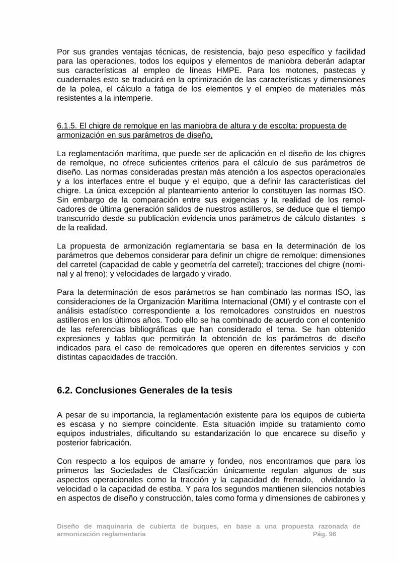
Diseño de maquinaria de cubierta de buques, en base a una propuesta razonada de armonización reglamentaria Pág. 96
Por sus grandes ventajas técnicas, de resistencia, bajo peso específico y facilidad para las operaciones, todos los equipos y elementos de maniobra deberán adaptar sus características al empleo de líneas HMPE. Para los motones, pastecas y cuadernales esto se traducirá en la optimización de las características y dimensiones de la polea, el cálculo a fatiga de los elementos y el empleo de materiales más resistentes a la intemperie. 6.1.5. El chigre de remolque en las maniobra de altura y de escolta: propuesta de armonización en sus parámetros de diseño, La reglamentación marítima, que puede ser de aplicación en el diseño de los chigres de remolque, no ofrece suficientes criterios para el cálculo de sus parámetros de diseño. Las normas consideradas prestan más atención a los aspectos operacionales y a los interfaces entre el buque y el equipo, que a definir las características del chigre. La única excepción al planteamiento anterior lo constituyen las normas ISO. Sin embargo de la comparación entre sus exigencias y la realidad de los remol-cadores de última generación salidos de nuestros astilleros, se deduce que el tiempo transcurrido desde su publicación evidencia unos parámetros de cálculo distantes s de la realidad. La propuesta de armonización reglamentaria se basa en la determinación de los parámetros que debemos considerar para definir un chigre de remolque: dimensiones del carretel (capacidad de cable y geometría del carretel); tracciones del chigre (nomi-nal y al freno); y velocidades de largado y virado. Para la determinación de esos parámetros se han combinado las normas ISO, las consideraciones de la Organización Marítima Internacional (OMI) y el contraste con el análisis estadístico correspondiente a los remolcadores construidos en nuestros astilleros en los últimos años. Todo ello se ha combinado de acuerdo con el contenido de las referencias bibliográficas que han considerado el tema. Se han obtenido expresiones y tablas que permitirán la obtención de los parámetros de diseño indicados para el caso de remolcadores que operen en diferentes servicios y con distintas capacidades de tracción.
6.2. Conclusiones Generales de la tesis
A pesar de su importancia, la reglamentación existente para los equipos de cubierta es escasa y no siempre coincidente. Esta situación impide su tratamiento como equipos industriales, dificultando su estandarización lo que encarece su diseño y posterior fabricación. Con respecto a los equipos de amarre y fondeo, nos encontramos que para los primeros las Sociedades de Clasificación únicamente regulan algunos de sus aspectos operacionales como la tracción y la capacidad de frenado, olvidando la velocidad o la capacidad de estiba. Y para los segundos mantienen silencios notables en aspectos de diseño y construcción, tales como forma y dimensiones de cabirones y

Diseño de maquinaria de cubierta de buques, en base a una propuesta razonada de armonización reglamentaria Pág. 97
barbotenes, accionamientos y elementos de control. En ambos casos, y en los parámetros coincidentes, las normas ISO establecen soluciones similares a las formuladas por las Sociedades de Clasificación pero además regulan otros muchos aspectos funcionales y de diseño. Para el equipo principal de fondeo, el molinete de ancla, en base al contenido de las normas ISO, y cumpliendo los requisitos establecidos por las Sociedades de Clasificación se ha propuesto un reglamento armonizado. Si a las normas establecidas, añadimos unas hipótesis de partida razonadas, tenemos la base para proponer un proceso de diseño que determine las características principales del molinete de acuerdo con los datos suministrados por el cliente. De manera referenciada se han propuesto procedimientos para determinar: el tipo de molinete, su forma de accionamiento, la potencia necesaria y la geometría de sus elementos constitutivos. Para los chigres de amarre, en base al contenido de las normas ISO y considerando la publicación de la OCIMF, así como los requisitos establecidos por las Sociedades de Clasificación también se ha propuesto un reglamento armonizado. Añadiendo a este reglamento la información básica necesaria para definir un chigre de amarre, se expone un procedimiento de diseño que calcula todos sus parámetros fundamentales de modo que quede completamente definido. El chigre de pesca es una máquina clave en la maniobra de pesca de un arrastrero. Sin embargo la única normativa que regula sus características es la de la International Standard Estándar Asociation (ISO) y mas concretamente la ISO 6115 - 1988 Shipbuilding – Trawl winches. De la comparación entre las exigencias operativas de la flota española de altura y el contenido de la norma ISO 6115 - 1988 Shipbuilding – Trawl winches en los aspectos de capacidad, tracción y velocidad, podemos concluir que los chigres de pesca instalados en arrastreros españoles son más potentes y polivalentes que los indicados en la norma ISO. Esto es debido a que las pesquerías del Atlántico en las que trabaja la flota de arrastre española, obliga a realizar la operación en caladeros muy diferentes, desde Mauritania o el banco Canario – Sahariano, con fondos situados a 70 m. de profundidad y mar en relativa calma hasta el Atlántico Norte (NAFO) donde la profundidad alcanza los 1.800 m. y suele haber fuerte oleaje. Tras un profundo análisis de los parámetros a considerar para el diseño de un chigre de pesca y la normativa existente se propone un procedimiento de diseño que facilita el cálculo de de sus elementos constitutivos y define las características operacionales de velocidad y tracción conducentes a conseguir un chigre de pesca lo mas estandarizado y versátil posible. Los motones, pastecas y cuadernales son elementos auxiliares fundamentales en los buques para la realización de maniobras, sin embargo su consideración como elementos auxiliares, hace que su tratamiento regulatorio se encuentre disperso en una variada normativa. Una vez analizada toda la normativa existente se formula una propuesta de armonización que incluye todos los requisitos funcionales y resistentes que debe cumplir todo equipo. También se define un procedimiento de cálculo que mayorando las cargas, fijando las hipótesis de partida y considerando los factores

Diseño de maquinaria de cubierta de buques, en base a una propuesta razonada de armonización reglamentaria Pág. 98
principales permite determinar las dimensiones y características de todos sus elementos constitutivos

Diseño de maquinaria de cubierta de buques, en base a una propuesta razonada de armonización reglamentaria Pág. 99
7. BIBLIOGRAFIA

Diseño de maquinaria de cubierta de buques, en base a una propuesta razonada de armonización reglamentaria Pág. 100

Diseño de maquinaria de cubierta de buques, en base a una propuesta razonada de armonización reglamentaria Pág. 101
Capítulo 7: Bibliografía
7.1. Bibliografía por artículo
7.1.1. Anchor windlasses: A design proposal to standardise regulations. [1] Carral Couce J.C, Carral Couce L.M, Fraguela Formoso J.A., Fernández Soto J.L., El chigre de remolque en las maniobras de altura y de escolta: propuesta de armonización en sus parámetros de diseño, DYNA – Industria y Energía 2013; 88, 395 - 399. DOI 10.6036/5657, ISSN: 0012-7361. [2] Allan, Robert G., A proposal for harmonized international regulations for the design and construction of tugboats In: Ter Haar J (eds) Towing Manual- Offshore an ocean towage with related shipping matters and opinions. Rotterdam: STC Group, 2010, pp 146-162 , ISBN 978 – 90 – 810900-2-5. [3] ISO 4568:1986. Shipbuilding sea going vessels- windlasses and anchor capstans. [4] Carral Couce L, Carral Couce J.C., Normas prácticas para el diseño de molinetes de anclas, Revista de Ingeniería Naval 1999; nº 761, 698 - 702. [5] ISO 7825. Deck machinery – general requirements. [6] ISO 1704. Shipbuilding – Stud- link anchor chains. [7] ISO 6482. Shipbuilding – Deck machinery – Warping end profiles. [8] Shigley J.E. and Mischke C. R.,. Mechanical Engineering Design. 3th ed Mac Graw Hill Companies 1985, p. 528, ISBN 968 – 451- 607– X. [9] Comas Turnes, E. Equipo y Servicios, Vol. II Fondeo, amarre y remolque: Escuela Técnica Superior de Ingenieros Navales – Universidad Politécnica de Madrid, 1985, p. 2-91. [10] ISO 3730: 2012. Shipbuilding – Mooring winches.
[11] EN 60529. Specification for degrees of protection provided by enclosures (IP code).
[12] EN 62262:2002. Degrees of protection provided by enclosures for electrical equipment against external mechanical impacts (IK code). [13] International Association of Classification Societies (IACS). Requirements concerning mooring, anchoring and towing” , 2007. [14] Freitag R. Bombas hidráulicas, In: Exner H., Freitag R., Geis H., Lang R., Ollolzer J, Schwab P., Sumpf E., Ostendorff U. and Reik M. Training Hidráulico. Compendio I

Diseño de maquinaria de cubierta de buques, en base a una propuesta razonada de armonización reglamentaria Pág. 102
"Fundamentos y componentes de la técnica de fluidos oleohidráulica. Mannesmann Rexroth, 1991, pp. 57-64, ISBN 3-8023-0266-4. [15] Carral Couce L., Carral Couce J. Fraguela Formoso J. González Filgueira G. Lamas Pardo G. Winche con caracteristicas de control avanzadas para labores de maniobra en superyates In: IPIN Actas del XXIII Congreso Internacional Copinaval , Isla Margarita, 30 septiembre – 4 octubre 2013, pp. 366. Isla Margarita: IPIN [16] Ostendorff U. Maquinas de pistones axiales, In: Exner H., Freitag R., Geis H., Lang R., Ollolzer J, Schwab P., Sumpf E., Ostendorff U. and Reik M. Training Hidráulico. Compendio I "Fundamentos y componentes de la técnica de fluidos oleohidráulica. Mannesmann Rexroth, 1991, pp. 93-122, ISBN 3-8023-0266-4. [17] ISO 21:1985 Shipbuilding – Cable lifters for stud – link anchors chain [18] ASTM F 765 – 93 Standars Specification for Wildcats, Ship Anchor Chain. [19] Niemann G., Tratado teórico práctico de elementos de máquinas: cálculo, diseño y construcción, ed. Labor. Barcelona, 1967, p 728, ISBN 84-335-6287-8. [20] DIN 743 - 2. Shaft and axles, calculation of load capacity. [21] Germanischer Lloyd´s. Rules for Classification and Construction. Ship Technology. Edition 2006. Part C - Chapter 1 7.1.2. Standardizing the design and production of mooring winches through more cohesive regulations [1] ISO 3730: 2012. Shipbuilding – Mooring winches. [2] Carral Couce L. Seguridad Marítima. In: Consideraciones sobre la seguridad marítima- actuaciones en evitación de la gestión subestandar. Ed La Coruña: J.B. Castro Ambroa y Copybelen S.L. Ute Coruña 1998, pp. 5 – 18 D.L.: C-565-2000 [3] Oil Companies International Marine Forum (OCIMF) “Mooring Equipment Guidelines – MEG3 Oil Companies International Marine Forum (OCIMF) 2008, capítulo 7, ISBN 9781- 1 -905331 321 [4] Stopford M., Maritime Economics, 3 th ed. Oxon: Routledge, 2009 p 74 Cap II The organization of the shipping market, ISBN 978-0-415-27558-3. [5] International Association of Classification Societies (IACS). Requirements concerning mooring, anchoring and towing. 2007 [6] Shellin T., Östergaard C., The vessel in port: mooring problems, Marine Structures 1995; 8, 451-479 [7] OMI MSC 1.175. Guidance on shipboard towing and mooring equipment. 2005
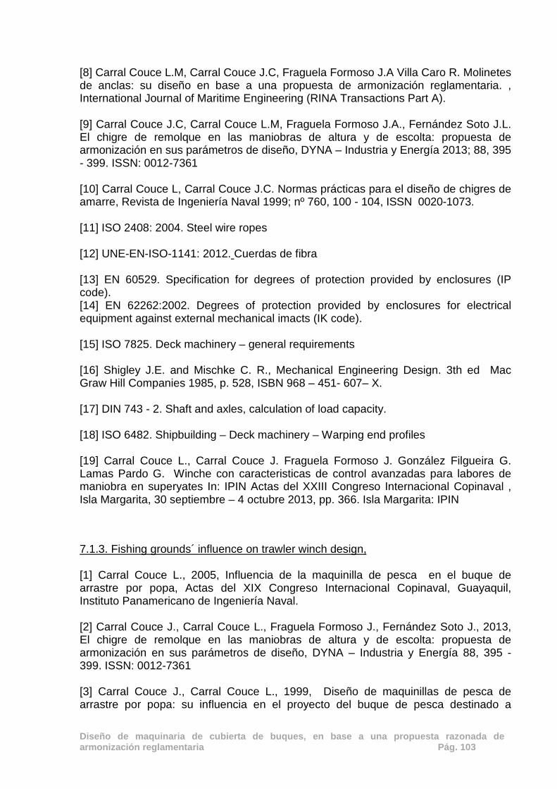
Diseño de maquinaria de cubierta de buques, en base a una propuesta razonada de armonización reglamentaria Pág. 103
[8] Carral Couce L.M, Carral Couce J.C, Fraguela Formoso J.A Villa Caro R. Molinetes de anclas: su diseño en base a una propuesta de armonización reglamentaria. , International Journal of Maritime Engineering (RINA Transactions Part A).
[9] Carral Couce J.C, Carral Couce L.M, Fraguela Formoso J.A., Fernández Soto J.L. El chigre de remolque en las maniobras de altura y de escolta: propuesta de armonización en sus parámetros de diseño, DYNA – Industria y Energía 2013; 88, 395 - 399. ISSN: 0012-7361 [10] Carral Couce L, Carral Couce J.C. Normas prácticas para el diseño de chigres de amarre, Revista de Ingeniería Naval 1999; nº 760, 100 - 104, ISSN 0020-1073. [11] ISO 2408: 2004. Steel wire ropes [12] UNE-EN-ISO-1141: 2012. Cuerdas de fibra [13] EN 60529. Specification for degrees of protection provided by enclosures (IP code). [14] EN 62262:2002. Degrees of protection provided by enclosures for electrical equipment against external mechanical imacts (IK code). [15] ISO 7825. Deck machinery – general requirements [16] Shigley J.E. and Mischke C. R., Mechanical Engineering Design. 3th ed Mac Graw Hill Companies 1985, p. 528, ISBN 968 – 451- 607– X. [17] DIN 743 - 2. Shaft and axles, calculation of load capacity. [18] ISO 6482. Shipbuilding – Deck machinery – Warping end profiles [19] Carral Couce L., Carral Couce J. Fraguela Formoso J. González Filgueira G. Lamas Pardo G. Winche con caracteristicas de control avanzadas para labores de maniobra en superyates In: IPIN Actas del XXIII Congreso Internacional Copinaval , Isla Margarita, 30 septiembre – 4 octubre 2013, pp. 366. Isla Margarita: IPIN 7.1.3. Fishing grounds´ influence on trawler winch design, [1] Carral Couce L., 2005, Influencia de la maquinilla de pesca en el buque de arrastre por popa, Actas del XIX Congreso Internacional Copinaval, Guayaquil, Instituto Panamericano de Ingeniería Naval. [2] Carral Couce J., Carral Couce L., Fraguela Formoso J., Fernández Soto J., 2013, El chigre de remolque en las maniobras de altura y de escolta: propuesta de armonización en sus parámetros de diseño, DYNA – Industria y Energía 88, 395 - 399. ISSN: 0012-7361 [3] Carral Couce J., Carral Couce L., 1999, Diseño de maquinillas de pesca de arrastre por popa: su influencia en el proyecto del buque de pesca destinado a

Diseño de maquinaria de cubierta de buques, en base a una propuesta razonada de armonización reglamentaria Pág. 104
caladeros comunitarios, Actas de las XXXV Sesiones técnicas de Ingeniería Naval, Vigo, AINE. [4] De la Cueva Sanz M., 1987, Artes y aparejos – tecnología pesquera, Ministerio de Agricultura, Pesca y Alimentación Secretaría Técnica, Madrid [5] FAO, 2007, Resumen informativo sobre la pesca por países – El Reino de España ftp://ftp.fao.org/FI/DOCUMENT/fcp/es/FI_CP_ES.pdf [6] Fyson J., Design of small fishing vessels, 1985, Farnham: Food and Agriculture Organizations of the United Nations by Fishing News Books, [7] Gil-Olcina A., Gómez-Mendoza J., Gómez J., 2001, Geografía de España, first edition - Ariel. pag 425. ISBN 84-344-3468-7 [8] ISO 6115:1988, Shipbuilding – Trawl winches. [9] ISO 2408, Steel wire rope for general purposes [10] ISO 7825, Deck machinery – general requirements. [11] ISO 6482, Shipbuilding – Deck machinery – Warping end profiles. [12] Von Brandt A., Vessel and Gear ,1995, in Jan Olof Traung (ed) Fishing boats of the world 1. Farnham: Food and Agriculture Organizations of the United Nations by Fishing News Books. [13] Khaled R.,Priour D.,Billard J.Y., 2012, Cable length optimization for trawl fuel consumption reduction, Ocean Engineering 58, 167 -179 [14] Koyama T.,,1970, A calculation method for matching trawl gear to towing power of trawlers Technical Conference on Fish Finding, Purse Seining and Aimed Trawling, Reykjavik (Iceland), 24-30 May 1970. [15] Lee C.W., Zhang C., Shin H., 2001, Simplifies Trawl system modeling and design of a depth control system using fuzzy logic, Fisheries Research 53, 83-84 [16] Martinez-Lopez A., Miguez-Gonzalez M., Diaz-Casás V.,Fariñas-Alvariño P., 2012, Desing-optimized and operational features to improve the economic results of fishing vessels, J. Engineering for the Maritime Environment 226, 51-61 [17] MAGRAMA - Ministerio de Agricultura, Alimentación y Medio Ambiente, 2013, Estadísticas pesqueras – Gobierno de España, http://magrama.gob.es/pesca/pesca en españa/censo de la flota pesquera/asp [18] Naciones Unidas, 1982, Acta final de le tercera conferencia de las Naciones Unidas sobre Derecho del Mar, w.w.w.un.org/depts/los/convention_agreements/texts/acta_final_esp.pd

Diseño de maquinaria de cubierta de buques, en base a una propuesta razonada de armonización reglamentaria Pág. 105
[19] Santos L., Nuñez Basañez J., 1994, Fundamentos de pesca, Fondo Editorial de Ingeniería Naval F.E.I.N, Madrid. [20] Solovyov V., Cherniavsky A., Computational and experimental analysis of trawl winches barrels deformations, 2013, Engineering Failure Analysis Volume 28, 160–165, dx.doi.org/10.1016/j.engfailanal.2012.10.007 [21] Trout, 1967, Moderm Deep Sea Trawling Gear, 3th – Fishing News Books Ltd 7.1.4. Diseño armonizado de motones, pastecas y cuadernales para el manejo de líneas de acero o sintéticas de elevado módulo (HMPE) en buques, [1]International Standard Organization, “ISO 3828: 1984 Shipbuilding and marine structures -- Deck machinery -- Vocabulary and symbols”, 1984 [2] International Standard Organization “ISO 8147: 1995. Derrick rigs and component parts – Vocabulary”,1995
[3] Carral Couce L., “Influencia de la maquinilla de pesca en el buque de arrastre por popa”, Actas del XIX Congreso Internacional Copinaval, Guayaquil, Instituto Panamericano de Ingeniería Naval, 2005. [4] Gaston M. J., “The tug boat, Hayne Publising, Sparkford , 2009.” – ISBN 9781844255276
[5] Unión Europea. “Directiva 2006/42/CE del Parlamento Europeo y del Consejo de 17 de mayo de 2006 relativa a las máquinas”. 2006
[6] González Blanco R., “Manual de estiba para mercancías sólidas”. Ediciones de la Universidad Politécnica de Catalunya, 2006, ISBN 978-84-8301-894-1 [7] Carral Couce J., Carral Couce L., Fraguela Formoso J., Fernández Soto J., “El chigre de remolque en las maniobras de altura y de escolta: propuesta de armonización en sus parámetros de diseño”, DYNA – Industria y Energía 88, 395 - 399. 2013, ISSN: 0012-7361
[8] Carral Couce J., Carral Couce L., Fraguela Formoso, J, Villa Caro R., “Anchor Windlasses, a desing proposal to standardise regulations”, International Journal of Maritime Engineering (RINA Transactions Part A) 157,95-104.2015 [9] Carral Couce J.,Carral Couce L., Fraguela Formoso, J, Villa Caro R Forthcoming, “Standardising the design and production of mooring winches through more cohesive regulations: a necessary step”, International Journal of Maritime Engineering (RINA Transactions Part A), 2015 [10] International Standard Organization, “ISO 4301-1:1986 Cranes and lifting appliances -- Classification -- Part 1: General”, 1986
[11] UNE “58-112-91. Grúas y aparatos de elevación. Clasificación. Parte 1: General”, 1991
Diseño de maquinaria de cubierta de buques, en base a una propuesta razonada de armonización reglamentaria Pág. 106
[12] DIN 15020-1:1974 FEM “Cable lifting appliances; principles relating to rope drives; calculation and construction”, 1974
[13] Martínez Ibarruri P., “Sociedad Franco Española de Alambres y Cables Aéreos” Imprenta Industrial S.A. Bilbao, 1965.
[14] DIN 15061: 1977 – 1- 77 “Perfiles de garganta para poleas”, 1974
[15] Ernest H., “Aparatos de elevación y transporte”. Editorial Blume. 1ª edición. Barcelona 1970.
[16] Larrodé E., Larrodé Pellicer E., Miravete de Marco A. ,“Grúas”, Centro Politécnico Superior – Universidad de Zaragoza, 1996.
[17] Crosby Group INC., “Advertencias e información sobre uso y mantenimiento de motones”, 2009 [18] FEM 1001/98. “Rules for the Design of Hoisting Appliances”. 1998
[19] UNE-EN “13001-2:2015. ”Seguridad de las grúas. Requisitos generales de diseño. Parte 2: Acciones de la carga”, 2015. [20] Unión Europea. “Directiva de Máquinas 2006/42”. 2006 [21] Dudley D.W., Radzevich S.P., “Handbook of Practical Gear Design”CRC Press, 1994
[22] Mott. R. L.”Diseño de elementos de maquinas”. Pearson Education. 4ª Edición. México. 2006. ISBN: 970-26-0812-0
[23] UNE 27- 122- 74.“Normas para la Construcción naval- Pastecas para cable de acero”, 1974. [24] International Standard Organization, “ISO 281/I – 77”
[25] Oil Companies International Marine Forum (OCIMF), “Mooring Equipment Guidelines – MEG3” Oil Companies International Marine Forum (OCIMF), 2008.
[26] Wardenier S., “Improved Efficiency in Connecting Tugs to Vessels “, Proceedings of the Tugnology 2011, 2011. [27] Griffin B., Nishimura. “High Performance Winches for High Performance Tugs – Winch and HMPE Rope Limitations”. Proceedings of the Tugnology 2009; Amsterdam 2009. [28] Nuttall A., “Service life of synthetic fibre ropes in deepwater lifting operations”, The 15th North Sea Offshore Cranes & Lifting Conference, 2010
[29] Crump T., Volpenhein K., and Chou R., “Samson Abrasion and Fibre Fatigue in High Performance, Synthetics for Ship Escort and Berthing “, USA, ITS 2008, Singapore, 2008.

Diseño de maquinaria de cubierta de buques, en base a una propuesta razonada de armonización reglamentaria Pág. 107
[30] Allan, R. G., “Escort Winch, Towline, and Tether System Analysis PWSRCAC RFP No. 8570.12.01 Final Report Project 212 – 030 - Prince William Sound Regional Citizens' Advisory Council.” [cited 2014 Jul]. Available from: http://www.pwsrcac.org/wp- content/uploads/filebase/programs/maritime_operations/tanker_escorts/escort_winch_towline_and_tether_system_analysis.pdf , 2012. [31] International Standard Organization, “ISO 3730: 2012. Shipbuilding – Mooring winches”. 2012 [32] Hensen H., “Tug use in port: a practical guide”, The Nautical Institute, 2nd edition, London. 2003. 7.1.5. El chigre de remolque en las maniobra de altura y de escolta: propuesta de armonización en sus parámetros de diseño, [1] Carral-Couce L, Carral-Couce JC., Alvarez-Feal C et al. “Sistema automático de maniobra para remolcadores del tipo escolta- Actas del XXII Congreso Internacional Copinaval”, Buenos Aires, Instituto Panamericano de Ingeniería Naval, 2011, ISBN 978-987-27394-0-9 [2] TerHaar J, “Towing Manual”, The Netherlands, STC Group, 2011, – ISBN 978 – 90 – 810900-2-5 [3] Carral-Couce L, Carral-Couce JC. “Diseño de maquinillas de pesca de arrastre pr popa: su influencia en el proyecto del buque de pesca destinado a caladeros comunitarios”, Revista de Ingeniería Naval, nº 769, 316- 326, 2000. [4] Carral-Couce L. “Influencia de la maquinilla de pesca en el buque de arrastre por popa- Actas del XIX Congreso Internacional Copinaval” , Guayaquil, Instituto Panamericano de Ingeniería Naval, 2005. [5] Hancox M. “Towing -The Oilfield Seamanship Series -Volume 4“, London, Oilfield Publications Limited, 1998, ISBN 1870945 492 . [6] OMI, “Guidelines for Safe Ocean Towing – MSC/ Circ. 884”, London, Organización Marítima Internacional, 2001. [7] Noble D. “Guidelines for the approval of towing vessels – 0021 /NO rev. 8”, London, GL Group Noble Denton Tools , 2010. [8] Carral-Couce L, Carral-Couce JC. “Normas prácticas para el diseño de chigres de carga y maniobra”, Revista de Ingeniería Naval, nº 761, 698- 702, 1999.
Diseño de maquinaria de cubierta de buques, en base a una propuesta razonada de armonización reglamentaria Pág. 108
7.2. Bibliografía común
En cada uno de los artículos se incluyen las referencias relacionadas con la materia objeto del estudio. La bibliografía más común, por citarse en al menos dos artículos, se incluye a continuación:
- Allan, Robert G., A proposal for harmonized international regulations for the
design and construction of tugboats In: Ter Haar J (eds) Towing Manual- Offshore an ocean towage with related shipping matters and opinions. Rotterdam: STC Group, 2010, pp 146-162 , ISBN 978 – 90
- ASTM F 765 – 93. Standars Specification for Wildcats, Ship Anchor Chain.
- Carral Couce J., Carral Couce L., 1999, Diseño de maquinillas de pesca de arrastre por popa: su influencia en el proyecto del buque de pesca destinado a caladeros comunitarios, Actas de las XXXV Sesiones técnicas de Ingeniería Naval, Vigo, AINE.
- Carral Couce J.C, Carral Couce L.M, Fraguela Formoso J.A., Fernández Soto J.L., El chigre de remolque en las maniobras de altura y de escolta: propuesta de armonización en sus parámetros de diseño, DYNA – Industria y Energía 2013; 88, 395 - 399. DOI 10.6036/5657, ISSN: 0012-7361.
- Carral Couce L. Seguridad Marítima. In: Consideraciones sobre la seguridad marítima- actuaciones en evitación de la gestión subestandar. Ed La Coruña: J.B. Castro Ambroa y Copybelen S.L. Ute Coruña 1998, pp. 5 – 18 D.L.: C-565-2000
- Carral Couce L, Carral Couce J.C. Normas prácticas para el diseño de chigres de amarre, Revista de Ingeniería Naval 1999; nº 760, 100 - 104, ISSN 0020-1073.
- Carral Couce L, Carral Couce J.C., Normas prácticas para el diseño de molinetes de anclas, Revista de Ingeniería Naval 1999; nº 761, 698 – 702
- Carral Couce L., 2005, Influencia de la maquinilla de pesca en el buque de arrastre por popa, Actas del XIX Congreso Internacional Copinaval, Guayaquil, Instituto Panamericano de Ingeniería Naval.
- Carral Couce L., Carral Couce J. Fraguela Formoso J. González Filgueira G. Lamas Pardo G. Winche con características de control avanzadas para labores de maniobra en superyates In: IPIN Actas del XXIII Congreso Internacional Copinaval , Isla Margarita, 30 septiembre – 4 octubre 2013, pp. 366. Isla Margarita: IPIN
- Comas Turnes, E. Equipo y Servicios, Vol. II Fondeo, amarre y remolque: Escuela Técnica Superior de Ingenieros Navales – Universidad Politécnica de Madrid, 1985, p. 2-91.
- De la Cueva Sanz M., 1987, Artes y aparejos – tecnología pesquera, Ministerio de Agricultura, Pesca y Alimentación Secretaría Técnica, Madrid

Diseño de maquinaria de cubierta de buques, en base a una propuesta razonada de armonización reglamentaria Pág. 109
- DIN 15020-1:1974 FEM “Cable lifting appliances; principles relating to rope drives;
calculation and construction”, 1974
- DIN 743 - 2. Shaft and axles, calculation of load capacity.
- EN 60529. Specification for degrees of protection provided by enclosures (IP code).
- EN 62262:2002. Degrees of protection provided by enclosures for electrical equipment against external mechanical impacts (IK code).
- Ernest H., “Aparatos de elevación y transporte”. Editorial Blume. 1ª edición. Barcelona 1970.
- FAO, 2007, Resumen informativo sobre la pesca por países – El Reino de España ftp://ftp.fao.org/FI/DOCUMENT/fcp/es/FI_CP_ES.pdf
- FEM 1001/98. “Rules for the Design of Hoisting Appliances”. 1998
- Fyson J., Design of small fishing vessels, 1985, Farnham: Food and Agriculture Organizations of the United Nations by Fishing News Books,
- Germanischer Lloyd´s. Rules for Classification and Construction. Ship Technology. Edition 2006. Part C - Chapter 1
- González Blanco R., “Manual de estiba para mercancías sólidas”. Ediciones de la Universidad Politécnica de Catalunya, 2006, ISBN 978-84-8301-894-1
- International Standard Organization, “ISO 3828: 1984 Shipbuilding and marine structures -- Deck machinery -- Vocabulary and symbols”, 1984
- ISO 21:1985 Shipbuilding – Cable lifters for stud – link anchors chain
- International Standard Organization, “ISO 4301-1:1986 Cranes and lifting appliances -- Classification -- Part 1: General”, 1986
- ISO 4568:1986. Shipbuilding sea going vessels- windlasses and anchor capstans.
- ISO 6115:1988, Shipbuilding – Trawl winches
- International Standard Organization “ISO 8147: 1995. Derrick rigs and component parts – Vocabulary”,1995
- ISO 2408: 2004. Steel wire ropes for general purposes
- International Association of Classification Societies (IACS). Requirements concerning mooring, anchoring and towing” , 2007.
- ISO 3730: 2012. Shipbuilding – Mooring winches

Diseño de maquinaria de cubierta de buques, en base a una propuesta razonada de armonización reglamentaria Pág. 110
- ISO 7825. Deck machinery – general requirements.
- ISO 6482. Shipbuilding – Deck machinery – Warping end profiles.
- Khaled R.,Priour D.,Billard J.Y., 2012, Cable length optimization for trawl fuel consumption reduction, Ocean Engineering 58, 167 -179
- Koyama T.,,1970, A calculation method for matching trawl gear to towing power of trawlers Technical Conference on Fish Finding, Purse Seining and Aimed Trawling, Reykjavik (Iceland), 24-30 May 1970.
- Larrodé E., Larrodé Pellicer E., Miravete de Marco A. ,“Grúas”, Centro Politécnico Superior – Universidad de Zaragoza, 1996.
- Lee C.W., Zhang C., Shin H., 2001, Simplifies Trawl system modeling and design of a depth control system using fuzzy logic, Fisheries Research 53, 83-84
- Martinez-Lopez A., Miguez-Gonzalez M., Diaz-Casás V.,Fariñas-Alvariño P., 2012, Desing-optimized and operational features to improve the economic results of fishing vessels, J. Engineering for the Maritime Environment 226, 51-61
- MAGRAMA - Ministerio de Agricultura, Alimentación y Medio Ambiente, 2013, Estadísticas pesqueras – Gobierno de España, http://magrama.gob.es/pesca/pesca en españa/censo de la flota pesquera/asp
- Naciones Unidas, 1982, Acta final de la tercera conferencia de las Naciones Unidas sobre Derecho del Mar, w.w.w.un.org/depts/los/convention_agreements/texts/acta_final_esp.pd
- Niemann G., Tratado teórico práctico de elementos de máquinas: cálculo, diseño y construcción, ed. Labor. Barcelona, 1967, p 728, ISBN 84-335-6287-8.
- Nuttall A., “Service life of synthetic fibre ropes in deepwater lifting operations”, The 15th North Sea Offshore Cranes & Lifting Conference, 2010
- OMI MSC 1.175. Guidance on shipboard towing and mooring equipment. 2005
- Ostendorff U. Maquinas de pistones axiales, In: Exner H., Freitag R., Geis H., Lang R., Ollolzer J, Schwab P., Sumpf E., Ostendorff U. and Reik M. Training Hidráulico. Compendio I "Fundamentos y componentes de la técnica de fluidos oleohidráulica. Mannesmann Rexroth, 1991, pp. 93-122, ISBN 3-8023-0266-4.
- Oil Companies International Marine Forum (OCIMF) “Mooring Equipment Guidelines – MEG3 Oil Companies International Marine Forum (OCIMF) 2008
- Santos L., Nuñez Basañez J., 1994, Fundamentos de pesca, Fondo Editorial de Ingeniería Naval F.E.I.N, Madrid.
- Shellin T., Östergaard C., The vessel in port: mooring problems, Marine Structures 1995; 8, 451-479.

Diseño de maquinaria de cubierta de buques, en base a una propuesta razonada de armonización reglamentaria Pág. 111
- Shigley J.E. and Mischke C. R.,. Mechanical Engineering Design. 3th ed Mac
Graw Hill Companies 1985, p. 528, ISBN 968 – 451- 607– X.
- Solovyov V., Cherniavsky A., Computational and experimental analysis of trawl winches barrels deformations, 2013, Engineering Failure Analysis Volume 28, 160–165, http:/ dx.doi.org/10.1016/j.engfailanal.2012.10.007
- Stopford M., Maritime Economics, 3 th ed. Oxon: Routledge, 2009 p 74 Cap II The
organization of the shipping market, ISBN 978-0-415-27558-3.
- Trout, 1967, Moderm Deep Sea Trawling Gear, 3th – Fishing News Books Ltd
- UNE “58-112-91. Grúas y aparatos de elevación. Clasificación. Parte 1: General”, 1991
- UNE-EN “13001-2:2015. ”Seguridad de las grúas. Requisitos generales de diseño. Parte 2: Acciones de la carga”, 2015.
- Von Brandt A., Vessel and Gear, 1995, in Jan Olof Traung (ed) Fishing boats of the world 1. Farnham: Food and Agriculture Organizations of the United Nations by Fishing News Books.