ball valve - 1516 series gearboxshop.sodeco-valves.com/content/tech/en-us/1516_r.pdfoeo-aeo 1...
TRANSCRIPT

www.sodeco-valves.com1 31/08/2017
L
DN
A
ØR
B
H2
H3
H1
DN L A QR B ØR H1 H2 H3 Kg
250 450 225 880 100,0 300 336 42 50,5 238,5
300 500 245 1250 104,5 300 417 51 51,0 349,0
Sub
ject
to
ch
an
ge
s
FIGURE: 1516AITR: Ball valve in steel, with gearbox 1516IITR: Ball valve in stainless steel, with gearbox
BALL VALVE - 1516 SERIESGearbox
DIMENSIONS: (mm)
The gearbox is calculated with a safety factor of 30% and max. differential pressure of 16 bar.For standard working conditions. OPTIONS: Limit switches, locking device , chainwheel.

www.sodeco-valves.com1 20/07/2016
Sub
ject
to
ch
an
ge
s
GENERAL FEATURES:- Split body - semi-trunnion - full bore - blow out proof stem- Face to face according to 3202 F18- Cavity balancing hole (standard = 5 mm diameter) in the top of the ball avoids overpressure in the cavity- With antistatic device- Temperature range: -20°C ~ 230°C- Max. working pressure: 20 bar
FLANGED BALL VALVEFig. 1516
DESIGN STANDARDS
Valves design DIN 3357, EN 1983
Body design DIN 3840
Shell thickness BS 5351
Flanges DIN 2501, EN 1092-1
Face to face dimensions DIN 3202 F18, EN 558-1 Series 27
Actuator mounting flange ISO 5211, DIN 3337
Shell finishing quality MSS SP 55
Marking BS 5351, EN 19, CE-PED
TESTS AND CERTIFICATES
Quality Assurance ISO 9001, CE-PED
Fire Safe certification BS 6755 Part 2, ISO 10497
Pressure testing DIN 3230, BS 6755 Part 1, EN 12266, NF E 29-203
Other ISO 14001, ATEX

www.sodeco-valves.com2 20/07/2016
12
4
11
8
47
14
9
10
72
58
26
39
Only DN 300Section A-A
Only DN 250
Sub
ject
to
ch
an
ge
s
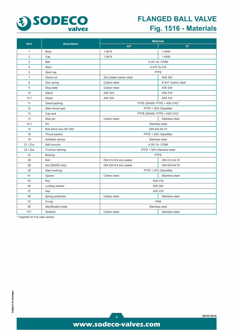
FLANGED BALL VALVEFig. 1516 - Materials
www.sodeco-valves.com3 20/07/2016
Sub
ject
to
ch
an
ge
s
FLANGED BALL VALVEFig. 1516 - Materials
Item DescriptionMaterials
AIT IIT
1 Body 1.0619 1.4408
2 Cap 1.0619 1.4408
3 Ball A 351 Gr. CF8M
4 Stem A 479 Tp.316
5 Seat ring PTFE
7 Gland nut Zinc plated carbon steel AISI 303
8 Disc spring Carbon steel E.N.P. Carbon steel
9 Stop plate Carbon steel AISI 304
10 Gland AISI 303 AISI 316
10.1 Gland AISI 303 AISI 316
11 Gland packing PTFE (DN300: PTFE + AISI 316)*
12 Stem thrust seal PTFE + 25% Glassfiber
13 Cap seal PTFE (DN300: PTFE + AISI 316)*
14 Stop pin Carbon steel Stainless steel
14.1 Pin Stainless steel
15 Bolt (Stud only DN 250) DIN 933 A4-70
18 Thrust washer PTFE + 25% Glassfiber
19 Antistatic device Stainless steel
21 / 21a Ball trunnion A 351 Gr. CF8M
22 / 22a Trunnion bearing PTFE + 50% Stainless steel
23 Bearing PTFE
26 Bolt DIN 912 8.8 zinc plated DIN 912 A4-70
28 Nut (DN250 only) DIN 934 8.8 zinc plated DIN 934 A4-70
39 Stem bushing PTFE + 25% Glassfiber
41 Spacer Carbon steel Stainless steel
43 Key AISI 316
46 Locking washer AISI 304
47 Key AISI 316
58 Spring protection Carbon steel Stainless steel
72 O-ring FKM
89 Identification plate Stainless steel
471 Retainer Carbon steel Stainless steel
* Graphite for Fire safe version
www.sodeco-valves.com4 20/07/2016
ØP
n x
ØS
Y
L1
L
Nh
DN 300
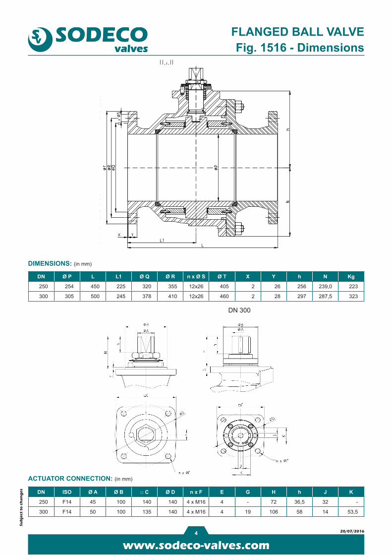
DN Ø P L L1 Ø Q Ø R n x Ø S Ø T X Y h N Kg
250 254 450 225 320 355 12x26 405 2 26 256 239,0 223
300 305 500 245 378 410 12x26 460 2 28 297 287,5 323
DN ISO Ø A Ø B □ C Ø D n x F E G H h J K
250 F14 45 100 140 140 4 x M16 4 - 72 36,5 32 -
300 F14 50 100 135 140 4 x M16 4 19 106 58 14 53,5
Sub
ject
to
ch
an
ge
s
FLANGED BALL VALVEFig. 1516 - Dimensions
DIMENSIONS: (in mm)
ACTUATOR CONNECTION: (in mm)

www.sodeco-valves.com5 20/07/2016
Body
0
10
20
30
40
-20 0 20 40 60 80 100 120 140 160 180 200 220 240
P (b
ar)
T (°C)
Sub
ject
to
ch
an
ge
s
FLANGED BALL VALVE
PRESSURE-TEMPERATURE CHART:
TORQUES: (in Nm) Kv VALUE: (in m³/h)
DN Differential pressure
250 1120
300 1800
Fig. 1516
DN Kv value
250 15.000
300 20.800

www.sodeco-valves.com1 08/12/2015
Sub
ject
to
ch
an
ge
s
GENERAL FEATURES:- Quarter turn gearbox for the operation of ball, butterfly and plug valves - Body in cast iron - Mounting flange acc. to ISO 5211- Removable stem drive inserts for 45° and 90° positions - Temperature range: -20°C ~ +120°C - Built in mechanical stops (± 5°) - IP 67
GEARBOXFIG. QR
Type Ratio Output torque (Nm) Input torque (Nm) Kg
QR-150 40 : 1 150 16 2
QR-210 37 : 1 330 28,5 4
QR-215 37 : 1 500 43 4
QR-550 34 : 1 1000 83 9
QR-880 38 : 1 2000 152 14
QR-1250 55 : 1 3250 171 22

www.sodeco-valves.com2 07/06/2016
Sub
ject
to
ch
an
ge
s
Materials - FIG. QR
MATERIALS:
Pos. Description Material
1 Shaft Steel
2 Body Cast iron GG25
3 Worm Carbon steel C45
4 Screws Steel ELVZ 8.8
5 Insert Sintered steel
6 Quadrant Ductile iron GGG 40
7 Coverplate Cast iron GG25
8 Screws Steel ELVZ 8.8
9 Position indicator Polypropylene
GEARBOX

www.sodeco-valves.com3 07/06/2016
A
E
L
G
ISO
521
1
F
K
BC
D
Sub
ject
to
ch
an
ge
s
Dimensions - FIG. QR
DIMENSIONS: (mm)
GEARBOX
Type A B C D E F G ØK L ISO 5211 Handwheel
QR-150 80 124 58 42,5 99,5 54,5 26,5 12 14 F05 - F07 PS125-12
QR-210 102 127,5 48 52 159 63 28,6 15 14 F05 - F07 - F10 PS160-15
QR-215 102 127,5 48 52 159 63 28,6 15 14 F05 - F07 - F10 PS200-15
QR-550 138 174 69 71 201 88 40,5 20 24 F10 - F14 SG300-20
QR-880 200 226 100 86 189 92,5 42 20 24 F10 - F14 SG500-20
QR-1250 220 258 110 104,5 230 102 - 20 24 F12 - F16 (F25 on demand) SG600-20

www.sodeco-valves.com4 07/06/2016
R
ØK ØK
Sub
ject
to
ch
an
ge
s
Handwheels - FIG. QRINSERTS
GEARBOX
HANDWHEELS
Gearbox type Insert type ØA S
QR-150 005VK08 25 8
QR-150 005VK09 25 9
QR-150 005VK11 25 11
QR-150 005VK14 25 14
QR-210 007VK14 32,15 14
QR-210 007VK17 32,15 17
QR-215 007VK14 32,15 14
QR-215 007VK17 32,15 17
QR-550 010VK17 45,3 17
QR-550 010VK19 45,3 19
QR-550 010VK22 45,3 22
QR-550 010VK27 45,3 27
QR-880/1250 150VK17 60 17
QR-880/1250 150VK19 60 19
QR-880/1250 150VK22 60 22
QR-880/1250 150VK27 60 27
QR-880/1250 150VK30 60 30
QR-880/1250 150VK36 60 36
Type PS ØK ØA B Type SG ØK ØA B
PS100-12 12 100 35 SG150-12 12 150 80
PS125-12 12 125 34 SG150-15 15 150 80
PS125-15 15 125 48 SG200-12 12 200 80
PS160-12 12 160 48 SG200-15 15 200 80
PS160-15 15 160 49 SG200-20 20 200 80
PS200-12 12 200 51 SG250-12 12 250 110
PS200-15 15 200 52 SG250-15 15 250 110
PS200-20 20 200 63 SG250-20 20 250 110
PS250-12 12 250 63 SG300-15 15 300 115
PS250-15 15 250 63 SG300-20 20 300 115
PS250-20 20 250 70 SG400-15 15 400 130
SG400-20 20 400 130
SG500-20 20 500 150
SG600-20 20 600 150