outdoor unit · 2019-02-06 · refrigerant piping length (one way, 4 unit total) calculation : xg =...
TRANSCRIPT
HFCutilized
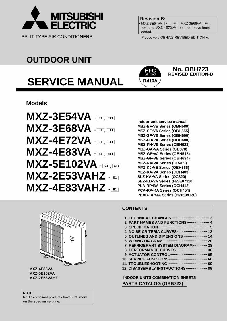
R410ASERVICE MANUALNo. OBH723
REVISED EDITION-B
OUTDOOR UNIT
NOTE: RoHS compliant products have <G> mark on the spec name plate.
PARTS CATALOG (OBB723)
Models
MXZ-3E54VA - E1 , ET1
MXZ-3E68VA - E1 , ET1
MXZ-4E72VA - E1 , ET1
MXZ-4E83VA - E1 , ET1
MXZ-5E102VA - E1 , ET1
MXZ-2E53VAHZ - E1
MXZ-4E83VAHZ - E1
CONTENTS
1. TECHNICAL CHANGES ··································· 32. PART NAMES AND FUNCTIONS ····················· 43. SPECIFICATION ················································ 54. NOISE CRITERIA CURVES ···························· 125. OUTLINES AND DIMENSIONS ······················ 146. WIRING DIAGRAM ·········································· 207. REFRIGERANT SYSTEM DIAGRAM ············· 288. PERFORMANCE CURVES ····························· 369. ACTUATOR CONTROL ··································· 65
10. SERVICE FUNCTIONS ···································· 6611. TROUBLESHOOTING ····································· 6912. DISASSEMBLY INSTRUCTIONS ···················· 89
INDOOR UNITS COMBINATION SHEETS
Indoor unit service manualMSZ-EF•VE Series (OBH589)MSZ-SF•VA Series (OBH555)MSZ-SF•VE Series (OBH600)MSZ-FD•VA Series (OBH488)MSZ-FH•VE Series (OBH623)MSZ-GA•VA Series (OB378)MSZ-GE•VA Series (OBH515)MSZ-GF•VE Series (OBH634)MFZ-KA•VA Series (OB409)MFZ-KJ•VE Series (OBH666)MLZ-KA•VA Series (OBH483)SLZ-KA•VA Series (OC320)SEZ-KD•VA Series (HWE07110)PLA-RP•BA Series (OCH412)PCA-RP•KA Series (OCH454)PEAD-RP•JA Series (HWE08130)
Please void OBH723 REVISED EDITION-A.
Revision B:• MXZ-3E54VA- E1 , ET1 , MXZ-3E68VA- E1 ,
ET1 and MXZ-4E72VA- E1 , ET1 have been added.
MXZ-4E83VAMXZ-5E102VAMXZ-2E53VAHZ
2
<Preparation before the repair service> Prepare the proper tools. Prepare the proper protectors. Provide adequate ventilation. After stopping the operation of the air conditioner, turn off the power-supply breaker and remove the power plug. Discharge the capacitor before the work involving the electric parts.
<Precautions during the repair service> Do not perform the work involving the electric parts with wet hands. Do not pour water into the electric parts. Do not touch the refrigerant. Do not touch the hot or cold areas in the refrigeration cycle. When the repair or the inspection of the circuit needs to be done without turning off the power, exercise great caution not to
touch the live parts.
Use the specifi ed refrigerant onlyNever use any refrigerant other than that specified.Doing so may cause a burst, an explosion, or fire when the unit is being used, serviced, or disposed of.Correct refrigerant is specified in the manuals and on the spec labels provided with our products.We will not be held responsible for mechanical failure, system malfunction, unit breakdown or accidents caused by failure to follow the instructions.
Revision A:• MXZ-2E53VAHZ- E1 and MXZ-4E83VAHZ- E1 have been added.• Values of air flow and fan speed for MXZ-5E102VA- E1 , ET1 have been modified.
Revision B:• MXZ-3E54VA- E1 , ET1 , MXZ-3E68VA- E1 , ET1 , and MXZ-4E72VA- E1 , ET1 have been added.
OBH723B
3
TECHNICAL CHANGES1
MXZ-4E83VA - E1 , ET1
MXZ-5E102VA - E1 , ET1
1. New model
MXZ-2E53VAHZ - E1
1. New model
MXZ-4E83VAHZ - E1
1. New model
MXZ-3E54VA - E1 , ET1
MXZ-3E68VA - E1 , ET1
MXZ-4E72VA - E1 , ET1
1. New model
OBH723B
4
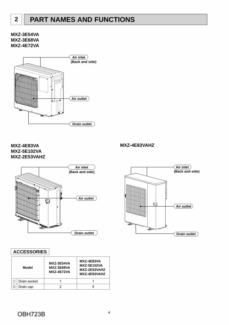
PART NAMES AND FUNCTIONS2
MXZ-4E83VAMXZ-5E102VAMXZ-2E53VAHZ
Air outlet
Drain outlet
Air inlet(Back and side)
Air outlet
Drain outlet
Air inlet(Back and side)
MXZ-4E83VAHZ
Air outlet
Drain outlet
Air inlet(Back and side)
MXZ-3E54VAMXZ-3E68VAMXZ-4E72VA
ACCESSORIES
ModelMXZ-3E54VAMXZ-3E68VAMXZ-4E72VA
MXZ-4E83VAMXZ-5E102VAMXZ-2E53VAHZMXZ-4E83VAHZ
Drain socket 1 1Drain cap 2 5
OBH723B
5
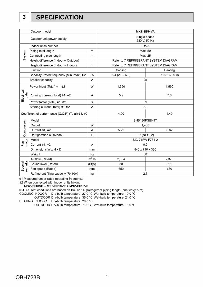
SPECIFICATION3
Outdoor model MXZ-3E54VA
Outdoor unit power supply Single phase230 V, 50 Hz
Sys
tem
Indoor units number 2 to 3Piping total length m Max. 50Connecting pipe length m Max. 25Height difference (Indoor ~ Outdoor) m Refer to 7 REFRIGERANT SYSTEM DIAGRAM.Height difference (Indoor ~ Indoor) m Refer to 7 REFRIGERANT SYSTEM DIAGRAM.Function Cooling HeatingCapacity Rated frequency (Min.-Max.) 2 kW 5.4 (2.9 - 6.8) 7.0 (2.6 - 9.0)Breaker capacity A 25
Ele
ctric
al d
ata
Power input (Total) 1, 2 W 1,350 1,590
Running current (Total) 1, 2 A 5.9 7.0
Power factor (Total) 1, 2 % 99Starting current (Total) 1, 2 A 7.0
Coeffi cient of performance (C.O.P) (Total) 1, 2 4.00 4.40
Com
pres
sor Model SNB130FGBH1T
Output W 1,400Current 1, 2 A 5.72 6.62Refrigeration oil (Model) L 0.7 (NEO22)
Fan
mot
or Model SIC-71FW-F764-2Current 1, 2 A 0.2Dimensions W x H x D mm 840 x 710 x 330Weight kg 58
Spe
cial
rem
arks
Air fl ow (Rated) m3 /h 2,334 2,376Sound level (Rated) dB(A) 50 53Fan speed (Rated) rpm 650 660Refrigerant fi lling capacity (R410A) kg 2.7
1 Measured under rated operating frequency.2 When connected with indoor units below.
MSZ-EF18VE + MSZ-EF18VE + MSZ-EF18VENOTE: Test conditions are based on ISO 5151. (Refrigerant piping length (one way): 5 m)COOLING INDOOR Dry-bulb temperature 27.0 °C Wet-bulb temperature 19.0 °C OUTDOOR Dry-bulb temperature 35.0 °C Wet-bulb temperature 24.0 °CHEATING INDOOR Dry-bulb temperature 20.0 °C OUTDOOR Dry-bulb temperature 7.0 °C Wet-bulb temperature 6.0 °C
OBH723B
6
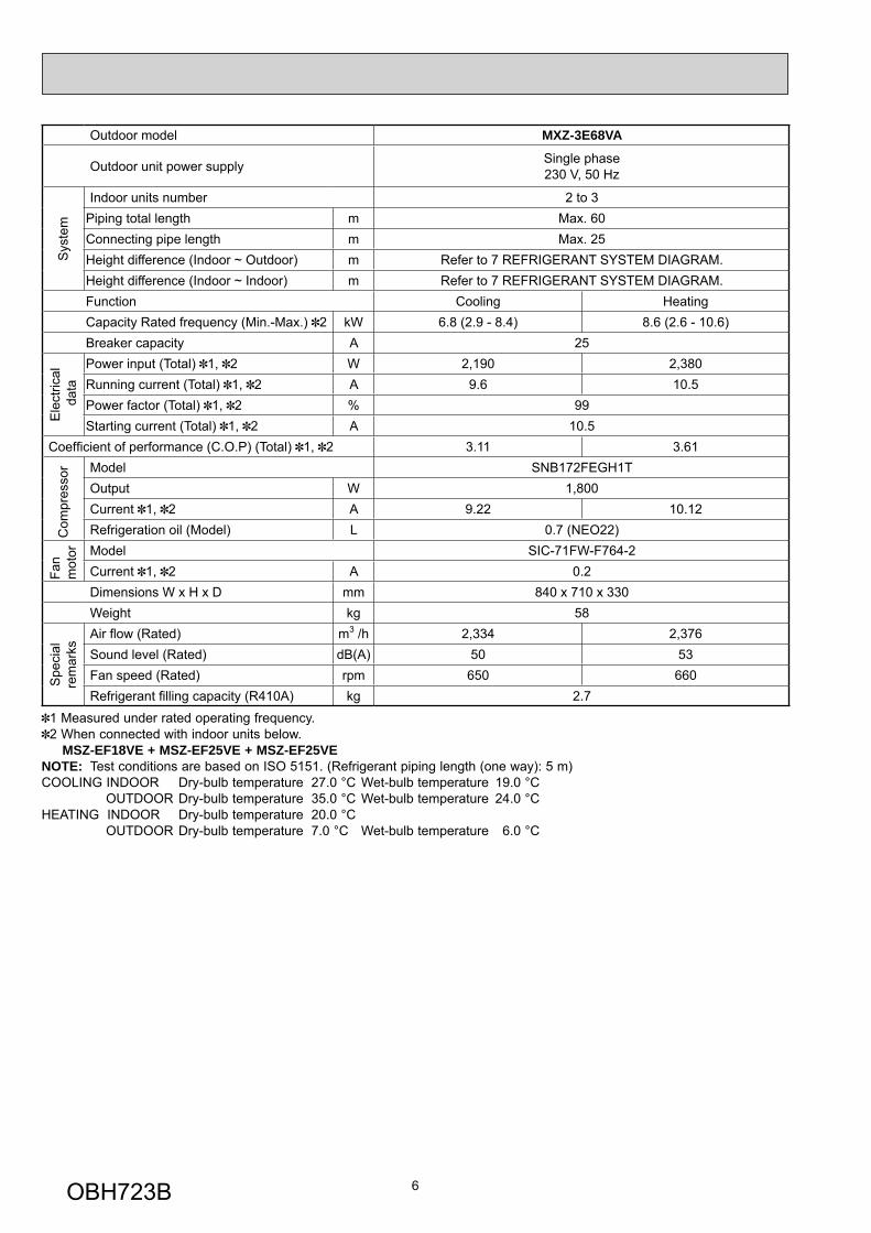
Outdoor model MXZ-3E68VA
Outdoor unit power supply Single phase230 V, 50 Hz
Sys
tem
Indoor units number 2 to 3Piping total length m Max. 60Connecting pipe length m Max. 25Height difference (Indoor ~ Outdoor) m Refer to 7 REFRIGERANT SYSTEM DIAGRAM.Height difference (Indoor ~ Indoor) m Refer to 7 REFRIGERANT SYSTEM DIAGRAM.Function Cooling HeatingCapacity Rated frequency (Min.-Max.) 2 kW 6.8 (2.9 - 8.4) 8.6 (2.6 - 10.6)Breaker capacity A 25
Ele
ctric
al d
ata
Power input (Total) 1, 2 W 2,190 2,380Running current (Total) 1, 2 A 9.6 10.5Power factor (Total) 1, 2 % 99Starting current (Total) 1, 2 A 10.5
Coeffi cient of performance (C.O.P) (Total) 1, 2 3.11 3.61
Com
pres
sor Model SNB172FEGH1T
Output W 1,800Current 1, 2 A 9.22 10.12Refrigeration oil (Model) L 0.7 (NEO22)
Fan
mot
or Model SIC-71FW-F764-2Current 1, 2 A 0.2Dimensions W x H x D mm 840 x 710 x 330Weight kg 58
Spe
cial
rem
arks
Air fl ow (Rated) m3 /h 2,334 2,376Sound level (Rated) dB(A) 50 53Fan speed (Rated) rpm 650 660Refrigerant fi lling capacity (R410A) kg 2.7
1 Measured under rated operating frequency.2 When connected with indoor units below.
MSZ-EF18VE + MSZ-EF25VE + MSZ-EF25VENOTE: Test conditions are based on ISO 5151. (Refrigerant piping length (one way): 5 m)COOLING INDOOR Dry-bulb temperature 27.0 °C Wet-bulb temperature 19.0 °C OUTDOOR Dry-bulb temperature 35.0 °C Wet-bulb temperature 24.0 °CHEATING INDOOR Dry-bulb temperature 20.0 °C OUTDOOR Dry-bulb temperature 7.0 °C Wet-bulb temperature 6.0 °C
OBH723B
7
Outdoor model MXZ-4E72VA
Outdoor unit power supply Single phase230 V, 50 Hz
Sys
tem
Indoor units number 2 to 4Piping total length m Max. 60Connecting pipe length m Max. 25Height difference (Indoor ~ Outdoor) m Refer to 7 REFRIGERANT SYSTEM DIAGRAM.Height difference (Indoor ~ Indoor) m Refer to 7 REFRIGERANT SYSTEM DIAGRAM.Function Cooling HeatingCapacity Rated frequency (Min.-Max.) 2 kW 7.2 (3.7 - 8.8) 8.6 (3.4 - 10.7)Breaker capacity A 25
Ele
ctric
al d
ata
Power input (Total) 1, 2 W 2,250 2,280Running current (Total) 1, 2 A 9.9 10.0Power factor (Total) 1, 2 % 99Starting current (Total) 1, 2 A 10.0
Coeffi cient of performance (C.O.P) (Total) 1, 2 3.20 3.77
Com
pres
sor Model SNB172FEGH1T
Output W 2,000Current 1, 2 A 9.46 9.56Refrigeration oil (Model) L 0.7 (NEO22)
Fan
mot
or Model SIC-71FW-F764-2Current 1, 2 A 0.2Dimensions W x H x D mm 840 x 710 x 330Weight kg 59
Spe
cial
rem
arks
Air fl ow (Rated) m3 /h 2,334 2,376Sound level (Rated) dB(A) 50 53Fan speed (Rated) rpm 650 660Refrigerant fi lling capacity (R410A) kg 2.7
1 Measured under rated operating frequency.2 When connected with indoor units below.
MSZ-EF18VE + MSZ-EF18VE + MSZ-EF18VE + MSZ-EF18VENOTE: Test conditions are based on ISO 5151. (Refrigerant piping length (one way): 5 m)COOLING INDOOR Dry-bulb temperature 27.0 °C Wet-bulb temperature 19.0 °C OUTDOOR Dry-bulb temperature 35.0 °C Wet-bulb temperature 24.0 °CHEATING INDOOR Dry-bulb temperature 20.0 °C OUTDOOR Dry-bulb temperature 7.0 °C Wet-bulb temperature 6.0 °C
OBH723B
8
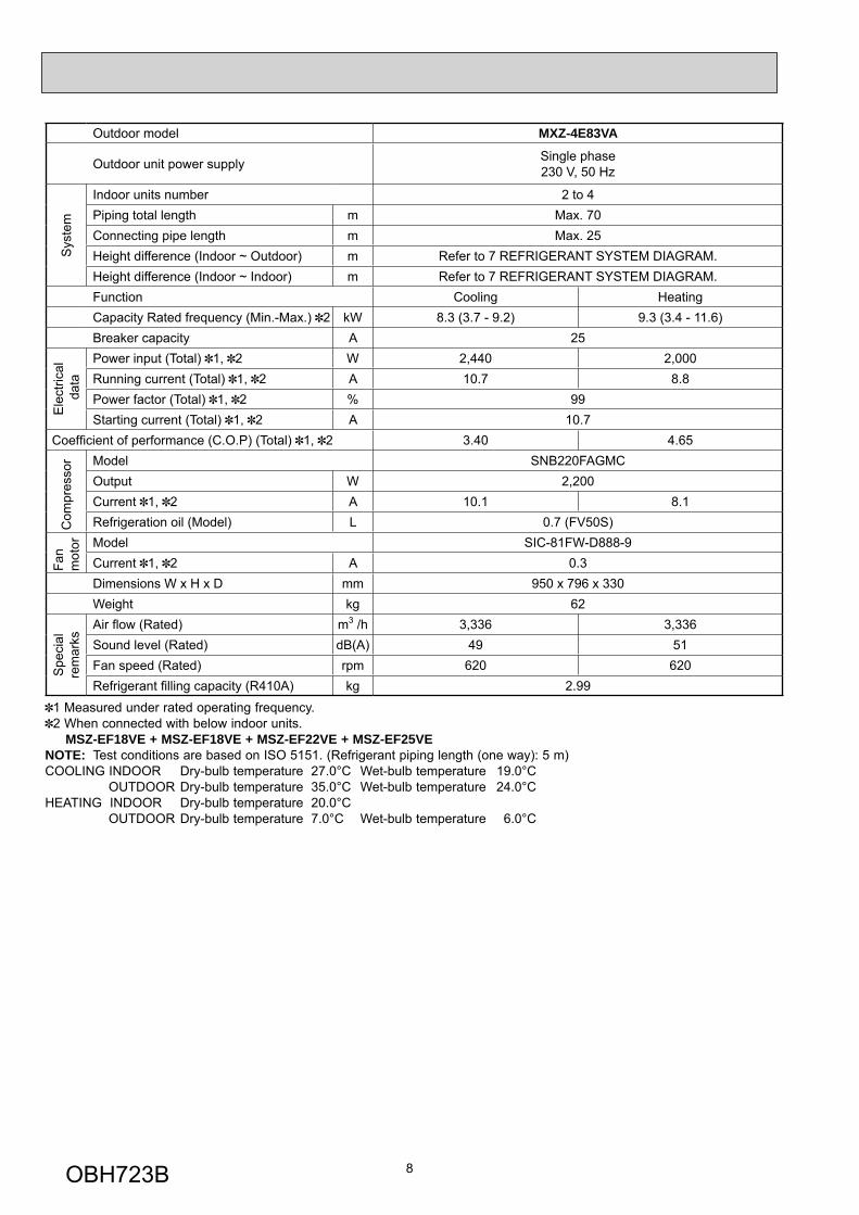
Outdoor model MXZ-4E83VA
Outdoor unit power supply Single phase230 V, 50 Hz
Sys
tem
Indoor units number 2 to 4Piping total length m Max. 70Connecting pipe length m Max. 25Height difference (Indoor ~ Outdoor) m Refer to 7 REFRIGERANT SYSTEM DIAGRAM.Height difference (Indoor ~ Indoor) m Refer to 7 REFRIGERANT SYSTEM DIAGRAM.Function Cooling HeatingCapacity Rated frequency (Min.-Max.) 2 kW 8.3 (3.7 - 9.2) 9.3 (3.4 - 11.6)Breaker capacity A 25
Ele
ctric
al d
ata
Power input (Total) 1, 2 W 2,440 2,000Running current (Total) 1, 2 A 10.7 8.8Power factor (Total) 1, 2 % 99Starting current (Total) 1, 2 A 10.7
Coeffi cient of performance (C.O.P) (Total) 1, 2 3.40 4.65
Com
pres
sor Model SNB220FAGMC
Output W 2,200Current 1, 2 A 10.1 8.1Refrigeration oil (Model) L 0.7 (FV50S)
Fan
mot
or Model SIC-81FW-D888-9Current 1, 2 A 0.3Dimensions W x H x D mm 950 x 796 x 330Weight kg 62
Spe
cial
rem
arks
Air fl ow (Rated) m3 /h 3,336 3,336Sound level (Rated) dB(A) 49 51Fan speed (Rated) rpm 620 620Refrigerant fi lling capacity (R410A) kg 2.99
1 Measured under rated operating frequency.2 When connected with below indoor units.
MSZ-EF18VE + MSZ-EF18VE + MSZ-EF22VE + MSZ-EF25VENOTE: Test conditions are based on ISO 5151. (Refrigerant piping length (one way): 5 m)COOLING INDOOR Dry-bulb temperature 27.0°C Wet-bulb temperature 19.0°C OUTDOOR Dry-bulb temperature 35.0°C Wet-bulb temperature 24.0°CHEATING INDOOR Dry-bulb temperature 20.0°C OUTDOOR Dry-bulb temperature 7.0°C Wet-bulb temperature 6.0°C
OBH723B

9
Outdoor model MXZ-5E102VA
Outdoor unit power supply Single phase230 V, 50 Hz
Sys
tem
Indoor units number 2 to 5Piping total length m Max. 80Connecting pipe length m Max. 25Height difference (Indoor ~ Outdoor) m Refer to 7 REFRIGERANT SYSTEM DIAGRAM.Height difference (Indoor ~ Indoor) m Refer to 7 REFRIGERANT SYSTEM DIAGRAM.Function Cooling HeatingCapacity Rated frequency (Min.-Max.) 2 kW 10.2 (3.9 - 11.0) 10.5 (4.1 - 14.0)Breaker capacity A 25
Ele
ctric
al d
ata
Power input (Total) 1, 2 W 3,150 2,340Running current (Total) 1, 2 A 13.8 10.3Power factor (Total) 1, 2 % 99Starting current (Total) 1, 2 A 13.8
Coeffi cient of performance (C.O.P) (Total) 1, 2 3.24 4.49
Com
pres
sor Model SNB220FAGMC
Output W 2,800Current 1, 2 A 13.0 9.4Refrigeration oil (Model) L 0.7 (FV50S)
Fan
mot
or Model SIC-81FW-D888-9Current 1, 2 A 0.5Dimensions W x H x D mm 950 x 796 x 330Weight kg 63
Spe
cial
rem
arks
Air fl ow (Rated) m3 /h 3,336 4,080Sound level (Rated) dB(A) 52 56Fan speed (Rated) rpm 620 750Refrigerant fi lling capacity (R410A) kg 2.99
1 Measured under rated operating frequency.2 When connected with below indoor units.
MSZ-EF18VE + MSZ-EF18VE + MSZ-EF22VE + MSZ-EF22VE + MSZ-EF22VENOTE: Test conditions are based on ISO 5151. (Refrigerant piping length (one way): 5 m)COOLING INDOOR Dry-bulb temperature 27.0°C Wet-bulb temperature 19.0°C OUTDOOR Dry-bulb temperature 35.0°C Wet-bulb temperature 24.0°CHEATING INDOOR Dry-bulb temperature 20.0°C OUTDOOR Dry-bulb temperature 7.0°C Wet-bulb temperature 6.0°C
OBH723B
10
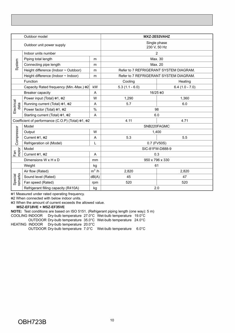
Outdoor model MXZ-2E53VAHZ
Outdoor unit power supply Single phase230 V, 50 Hz
Sys
tem
Indoor units number 2Piping total length m Max. 30Connecting pipe length m Max. 20Height difference (Indoor ~ Outdoor) m Refer to 7 REFRIGERANT SYSTEM DIAGRAM.Height difference (Indoor ~ Indoor) m Refer to 7 REFRIGERANT SYSTEM DIAGRAM.Function Cooling HeatingCapacity Rated frequency (Min.-Max.) 2 kW 5.3 (1.1 - 6.0) 6.4 (1.0 - 7.0)Breaker capacity A 16/25 3
Ele
ctric
al d
ata
Power input (Total) 1, 2 W 1,290 1,360Running current (Total) 1, 2 A 5.7 6.0Power factor (Total) 1, 2 % 98Starting current (Total) 1, 2 A 6.0
Coeffi cient of performance (C.O.P) (Total) 1, 2 4.11 4.71
Com
pres
sor Model SNB220FAGMC
Output W 1,400Current 1, 2 A 5.3 5.5Refrigeration oil (Model) L 0.7 (FV50S)
Fan
mot
or Model SIC-81FW-D888-9Current 1, 2 A 0.3Dimensions W x H x D mm 950 x 796 x 330Weight kg 61
Spe
cial
rem
arks
Air fl ow (Rated) m3 /h 2,820 2,820Sound level (Rated) dB(A) 45 47Fan speed (Rated) rpm 520 520Refrigerant fi lling capacity (R410A) kg 2.0
1 Measured under rated operating frequency.2 When connected with below indoor units.3 When the amount of current exceeds the allowed value.
MSZ-EF18VE + MSZ-EF35VENOTE: Test conditions are based on ISO 5151. (Refrigerant piping length (one way): 5 m)COOLING INDOOR Dry-bulb temperature 27.0°C Wet-bulb temperature 19.0°C OUTDOOR Dry-bulb temperature 35.0°C Wet-bulb temperature 24.0°CHEATING INDOOR Dry-bulb temperature 20.0°C OUTDOOR Dry-bulb temperature 7.0°C Wet-bulb temperature 6.0°C
OBH723B
11
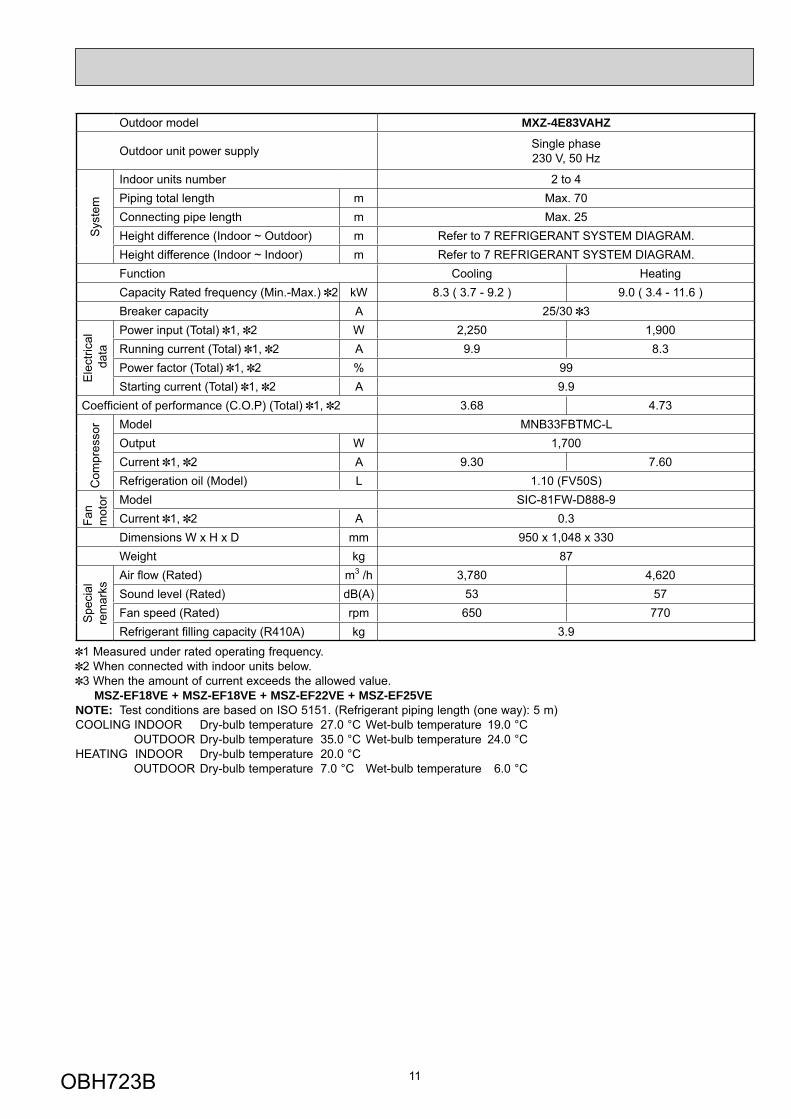
Outdoor model MXZ-4E83VAHZ
Outdoor unit power supply Single phase230 V, 50 Hz
Sys
tem
Indoor units number 2 to 4Piping total length m Max. 70Connecting pipe length m Max. 25Height difference (Indoor ~ Outdoor) m Refer to 7 REFRIGERANT SYSTEM DIAGRAM.Height difference (Indoor ~ Indoor) m Refer to 7 REFRIGERANT SYSTEM DIAGRAM.Function Cooling HeatingCapacity Rated frequency (Min.-Max.) 2 kW 8.3 ( 3.7 - 9.2 ) 9.0 ( 3.4 - 11.6 )Breaker capacity A 25/30 3
Ele
ctric
al d
ata
Power input (Total) 1, 2 W 2,250 1,900Running current (Total) 1, 2 A 9.9 8.3Power factor (Total) 1, 2 % 99Starting current (Total) 1, 2 A 9.9
Coeffi cient of performance (C.O.P) (Total) 1, 2 3.68 4.73
Com
pres
sor Model MNB33FBTMC-L
Output W 1,700Current 1, 2 A 9.30 7.60Refrigeration oil (Model) L 1.10 (FV50S)
Fan
mot
or Model SIC-81FW-D888-9Current 1, 2 A 0.3Dimensions W x H x D mm 950 x 1,048 x 330Weight kg 87
Spe
cial
rem
arks
Air fl ow (Rated) m3 /h 3,780 4,620Sound level (Rated) dB(A) 53 57Fan speed (Rated) rpm 650 770Refrigerant fi lling capacity (R410A) kg 3.9
1 Measured under rated operating frequency.2 When connected with indoor units below.3 When the amount of current exceeds the allowed value.
MSZ-EF18VE + MSZ-EF18VE + MSZ-EF22VE + MSZ-EF25VE NOTE: Test conditions are based on ISO 5151. (Refrigerant piping length (one way): 5 m)COOLING INDOOR Dry-bulb temperature 27.0 °C Wet-bulb temperature 19.0 °C OUTDOOR Dry-bulb temperature 35.0 °C Wet-bulb temperature 24.0 °CHEATING INDOOR Dry-bulb temperature 20.0 °C OUTDOOR Dry-bulb temperature 7.0 °C Wet-bulb temperature 6.0 °C
OBH723B
12
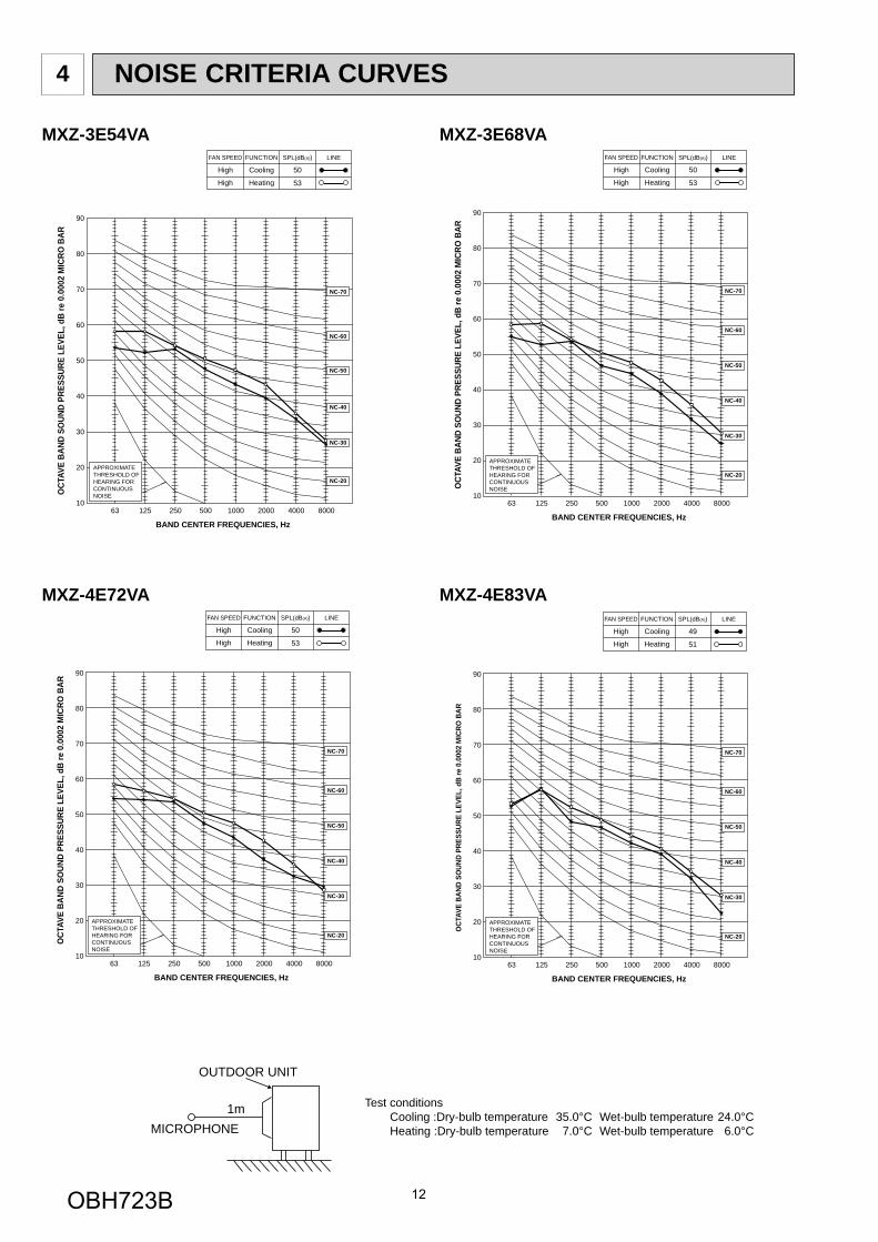
NOISE CRITERIA CURVES4
90
80
70
60
50
40
30
20
1063 125 250 500 1000 2000 4000 8000
APPROXIMATETHRESHOLD OFHEARING FORCONTINUOUSNOISE
NC-60
NC-50
NC-40
NC-30
NC-20
NC-70
OCT
AVE
BAND
SO
UND
PRES
SURE
LEV
EL, d
B re
0.0
002
MIC
RO B
AR
BAND CENTER FREQUENCIES, Hz
CoolingHigh
FUNCTIONFAN SPEED
HeatingHigh
49
SPL(dB(A))
51
LINE
OUTDOOR UNIT
MICROPHONE1m Test conditions
Cooling :Dry-bulb temperature 35.0°C Wet-bulb temperature 24.0°C Heating :Dry-bulb temperature 7.0°C Wet-bulb temperature 6.0°C
MXZ-4E83VA
90
80
70
60
50
40
30
20
1063 125 250 500 1000 2000 4000 8000
APPROXIMATETHRESHOLD OFHEARING FORCONTINUOUSNOISE
NC-60
NC-50
NC-40
NC-30
NC-20
NC-70
OCT
AVE
BAND
SO
UND
PRES
SURE
LEV
EL, d
B re
0.0
002
MIC
RO B
AR
BAND CENTER FREQUENCIES, Hz
CoolingHigh
FUNCTIONFAN SPEED
HeatingHigh
50
SPL(dB(A))
53
LINE
MXZ-3E54VA MXZ-3E68VA
MXZ-4E72VA
OBH723B
13
90
80
70
60
50
40
30
20
1063 125 250 500 1000 2000 4000 8000
APPROXIMATETHRESHOLD OFHEARING FORCONTINUOUSNOISE
NC-60
NC-50
NC-40
NC-30
NC-20
NC-70
OCT
AVE
BAND
SO
UND
PRES
SURE
LEV
EL, d
B re
0.0
002
MIC
RO B
AR
BAND CENTER FREQUENCIES, Hz
CoolingHigh
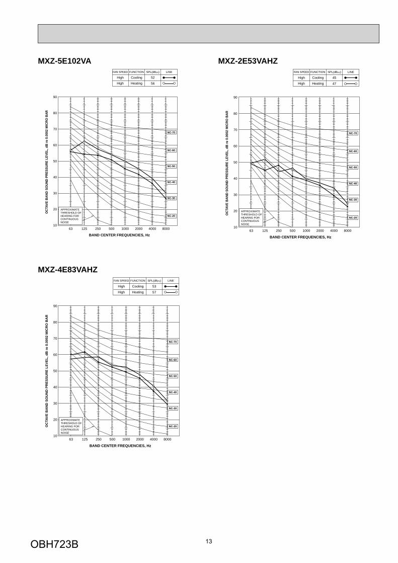
FUNCTIONFAN SPEED
HeatingHigh
52
SPL(dB(A))
56
LINE
MXZ-5E102VA
MXZ-4E83VAHZ
MXZ-2E53VAHZ
90
80
70
60
50
40
30
20
1063 125 250 500 1000 2000 4000 8000
APPROXIMATETHRESHOLD OFHEARING FORCONTINUOUSNOISE
NC-60
NC-50
NC-40
NC-30
NC-20
NC-70
OC
TAVE
BA
ND
SO
UN
D P
RES
SUR
E LE
VEL,
dB
re 0
.000
2 M
ICR
O B
AR
BAND CENTER FREQUENCIES, Hz
CoolingHigh
FUNCTIONFAN SPEED
HeatingHigh
53
SPL(dB(A))
57
LINE
90
80
70
60
50
40
30
20
1063 125 250 500 1000 2000 4000 8000
APPROXIMATETHRESHOLD OFHEARING FORCONTINUOUSNOISE
NC-60
NC-50
NC-40
NC-30
NC-20
NC-70
OCT
AVE
BAND
SO
UND
PRES
SURE
LEV
EL, d
B re
0.0
002
MIC
RO B
AR
BAND CENTER FREQUENCIES, Hz
CoolingHigh
FUNCTIONFAN SPEED
HeatingHigh
45
SPL(dB(A))
47
LINE
OBH723B
14
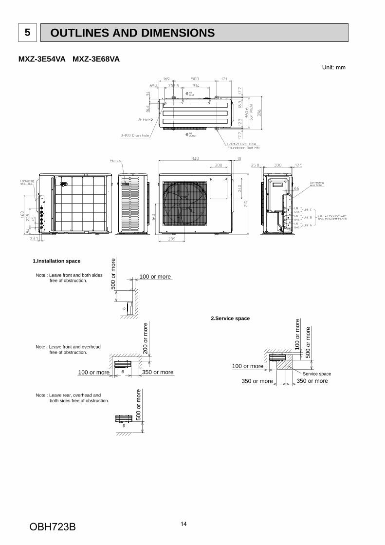
OUTLINES AND DIMENSIONS5
1.Installation space
Note : Leave front and both sides free of obstruction.
Note : Leave rear, overhead and both sides free of obstruction.
500
or m
ore
100 or more
Note : Leave front and overhead free of obstruction.
100 or more 350 or more
200
or m
ore
500
or m
ore
2.Service space
100
or m
ore
500
or m
ore
350 or more350 or more
100 or moreService space
MXZ-3E54VA MXZ-3E68VAUnit: mm
OBH723B
15
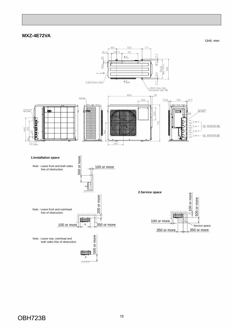
1.Installation space
Note : Leave front and both sides free of obstruction.
Note : Leave rear, overhead and both sides free of obstruction.
500
or m
ore
100 or more
Note : Leave front and overhead free of obstruction.
100 or more 350 or more
200
or m
ore
500
or m
ore
2.Service space10
0 or
mor
e
500
or m
ore
350 or more350 or more
100 or moreService space
MXZ-4E72VAUnit: mm
OBH723B
16
MXZ-4E83VAUnit: mm
Air in
Air in
Air in
Air out
OBH723B
17
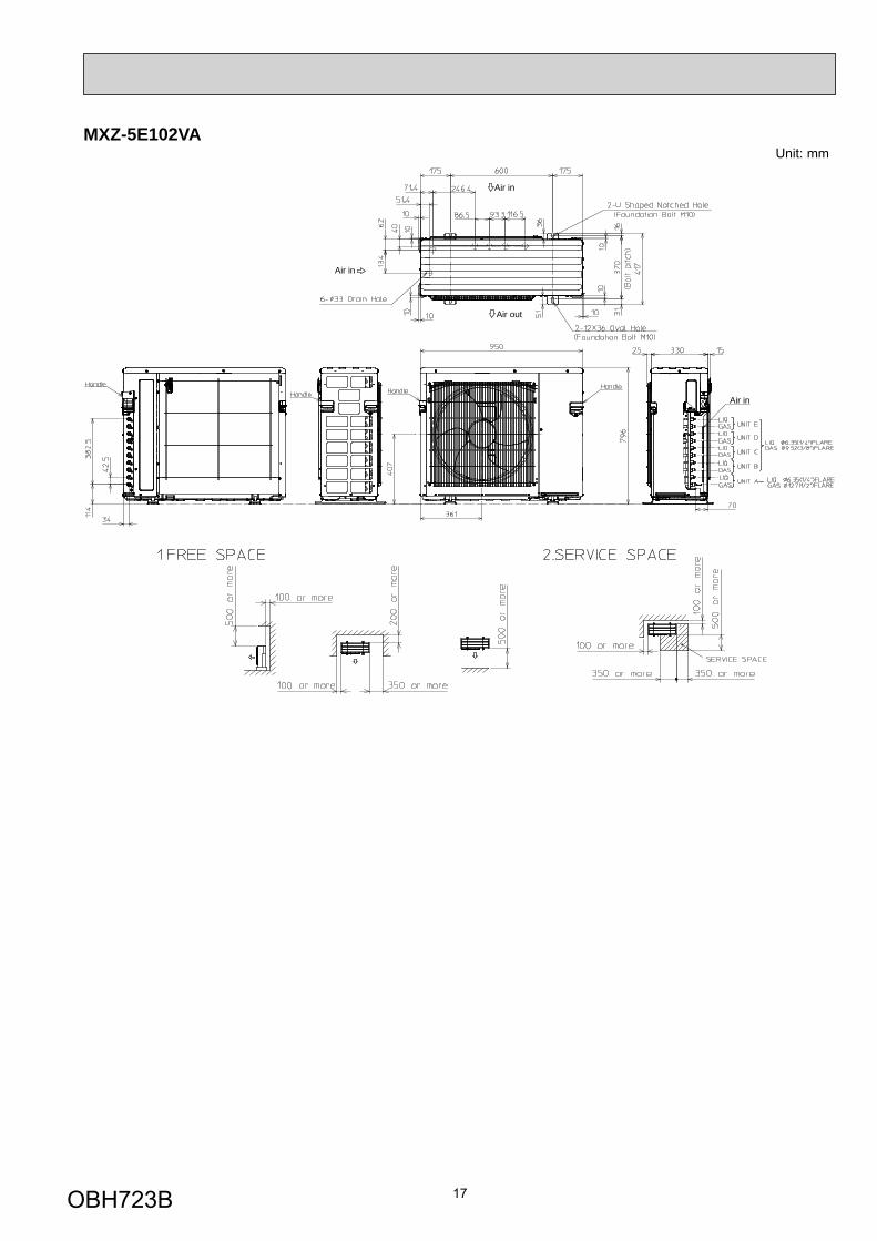
MXZ-5E102VAUnit: mm
Air in
Air in
Air in
Air out
OBH723B

18
Unit: mmMXZ-2E53VAHZ
OBH723B
19
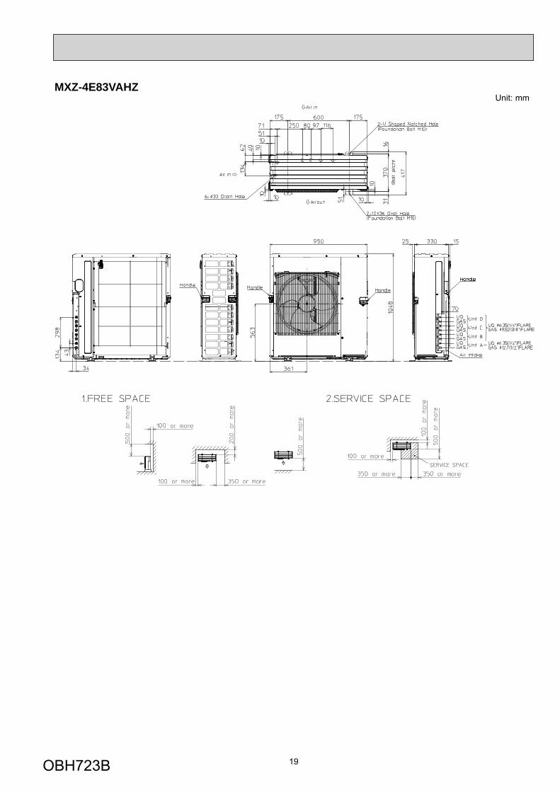
MXZ-4E83VAHZUnit: mm
OBH723B
20
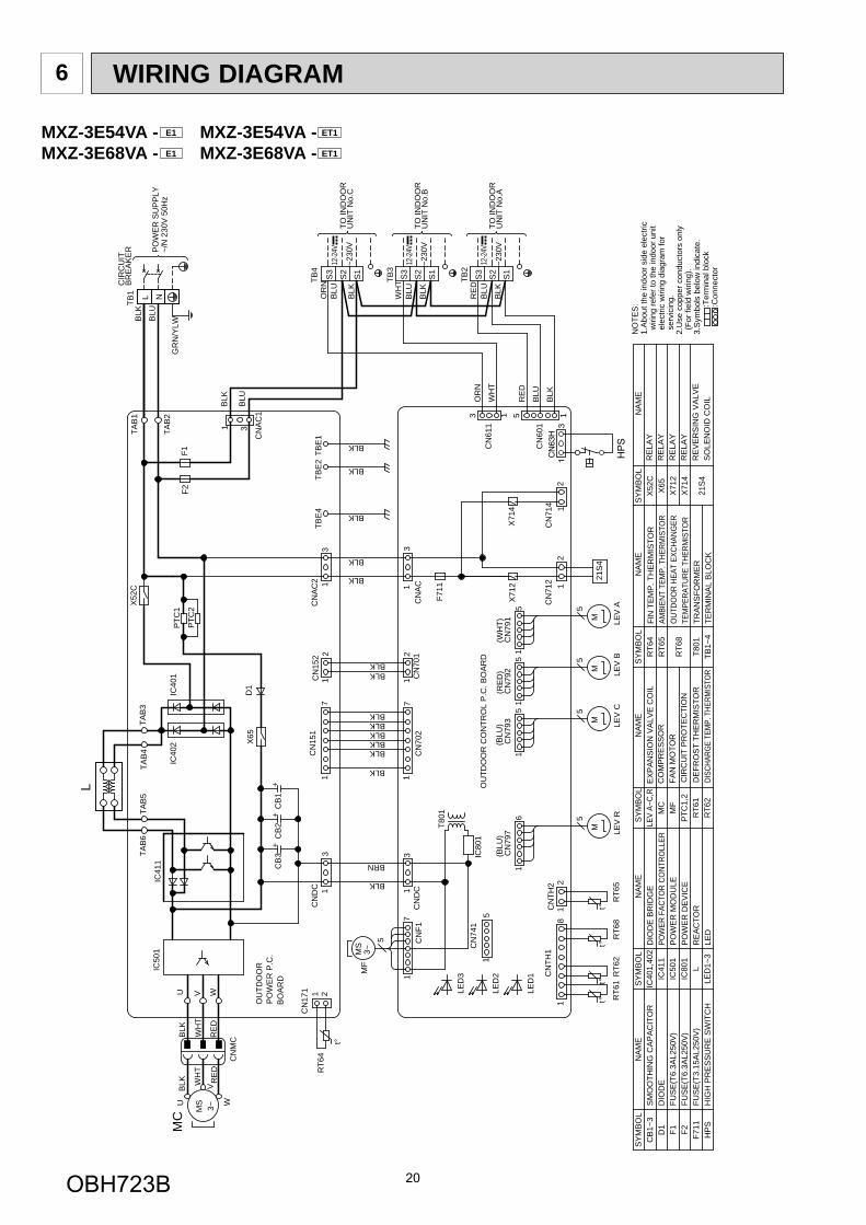
MXZ-3E54VA - E1 MXZ-3E54VA - ET1
MXZ-3E68VA - E1 MXZ-3E68VA - ET1
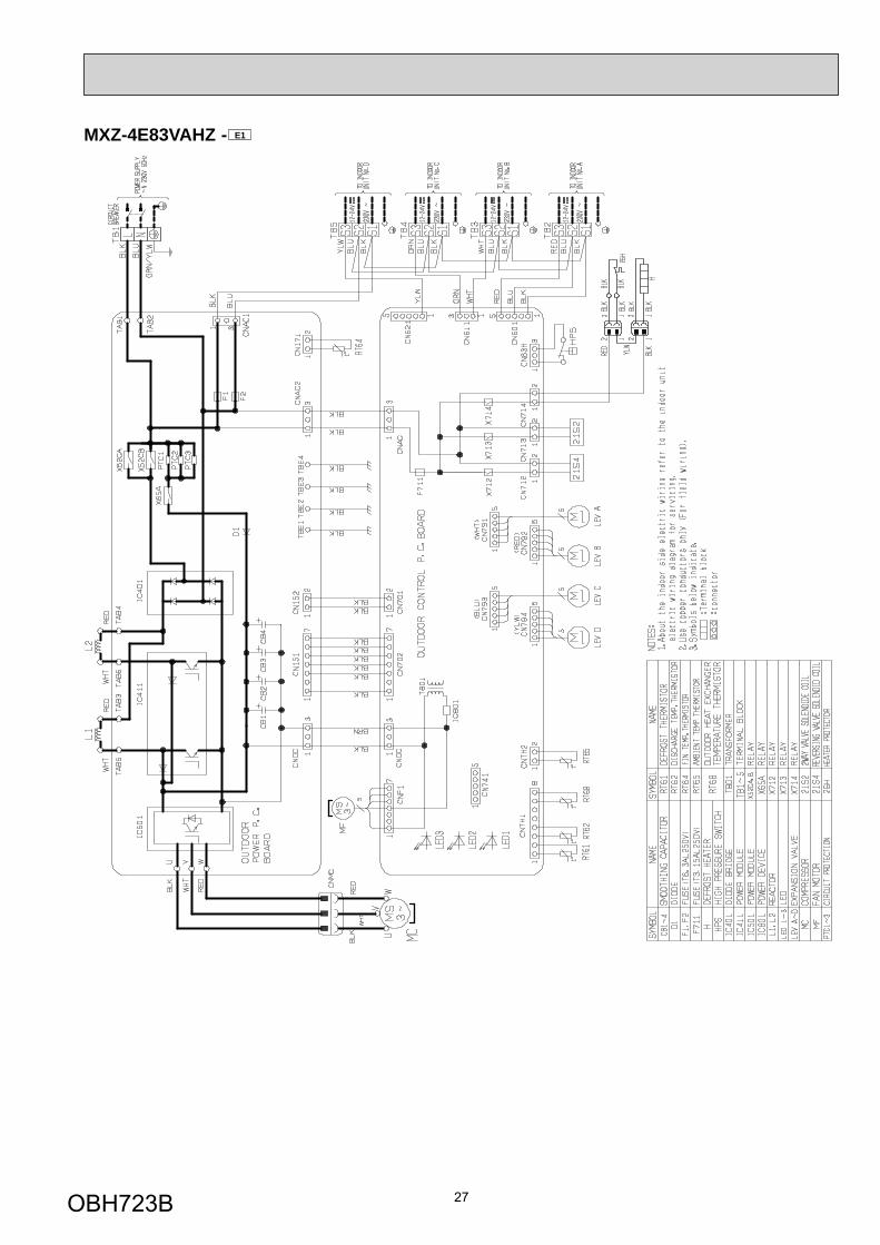
WIRING DIAGRAM6
t°21
S4
t°°t
°t
L
MS 3~
t°
RT6
4
M LEV
RLE
V C
LEV
ALE
V B
RT6
2R
T61
X71
4X
712
F711
TO IN
DO
OR
UN
IT N
o.C
TO IN
DO
OR
UN
IT N
o.A
TO IN
DO
OR
UN
IT N
o.B
TB2
TB3
TB4
12-2
4V
~230
V
~230
V
12-2
4V
~230
V
12-2
4V
RT6
8R
T65
MM
M
MS
3~M
F
T801
BLK W
HT
RE
DR
ED
WH
T
BLK
U
V
W
MC
CB
3C
B2
CB
1B
OA
RD
PO
WE
R P
.C.
OU
TDO
OR
OU
TDO
OR
CO
NTR
OL
P.C
. BO
AR
D
F1F2
TB1
BR
EA
KE
RC
IRC
UIT
PO
WE
R S
UP
PLY
~/N
230
V 5
0Hz
IC80
1
5
HPS
CN63
H1
3
16
CN
797
CN
714 1
2
CN
AC
CN
712 1
2
S1
S2
S3
S1
S2
S3
S1
S2
S3
15
CN
741
D1
IC40
1IC
402
21C
N17
1
18
CN
TH1
21C
NTH
2
55
5
CN
MC
15
51
17
1
CN
792
CN
791
CN
793
15
5
71
CN
F1C
N70
21
3C
ND
C
U V W
13
1C
N15
11
7C
ND
CC
NA
C2
CN
7012
112
CN
152
IC50
1IC
411
TAB
4TA
B6
TAB
5TA
B3
X52
C
3
5
CN
601
13
CN
611
1
TAB
1
TAB
2
31
CN
AC
1
3TB
E4
TBE
2TB
E1
PTC
1
PTC
2
X65
L N
(BLU
)B
LK
BLU
RE
D
BLK
BLU
WH
T
BLK
BLU
OR
N
BLK
BLK
BRN
BLK
BLK
(RE
D)
(WH
T)(B
LU)
BLKBLKBLKBLKBLK
BLKBLK
BLK BLU R
ED
BLU
BLK
BLK
BLK
BLK
BLK
BLU
GR
N/Y
LW
WH
T
OR
N
++
+
LEV
A~C,
RM
CM
FP
TC1,
2R
T61
RT6
2
X52
CX
65X
712
X71
4
21S
4
RE
LAY
RE
LAY
RE
LAY
RE
LAY
RE
VE
RS
ING
VA
LVE
SO
LEN
OID
CO
ILD
EFR
OS
T TH
ER
MIS
TOR
FIN
TE
MP
. TH
ER
MIS
TOR
AMBI
ENT
TEM
P. T
HERM
ISTO
RO
UTDO
OR
HEAT
EXC
HANG
ERTE
MPE
RATU
RE T
HERM
ISTO
RTR
AN
SFO
RM
ER
TER
MIN
AL
BLO
CK
RT6
4R
T65
RT6
8
T801
TB1~
4
FAN
MO
TOR
CO
MP
RE
SS
OR
EX
PA
NS
ION
VA
LVE
CO
IL
DISC
HARG
E TE
MP.
THE
RMIS
TOR
SM
OO
THIN
G C
AP
AC
ITO
RD
IOD
EFU
SE
(T6.
3AL2
50V
)FU
SE
(T6.
3AL2
50V
)FU
SE
(T3.
15A
L250
V)
HIG
H P
RE
SS
UR
E S
WIT
CH
CB
1~3
D1
F1 F2 F711
HP
S
CIR
CU
IT P
RO
TEC
TIO
N
NO
TES
:1.
Abo
ut th
e in
door
sid
e el
ectri
c w
iring
refe
r to
the
indo
or u
nit
ele
ctric
wiri
ng d
iagr
am fo
r s
ervi
cing
.2.
Use
cop
per c
ondu
ctor
s on
ly (
For f
ield
wiri
ng).
3.S
ymbo
ls b
elow
indi
cate
.
:T
erm
inal
blo
ck
:C
onne
ctor
SY
MB
OL
NA
ME
SY
MB
OL
SY
MB
OL
SY
MB
OL
NA
ME
NA
ME
NA
ME
SY
MB
OL
NA
ME
DIO
DE
BR
IDG
EPO
WER
FAC
TOR
CONT
ROLL
ERP
OW
ER
MO
DU
LEP
OW
ER
DE
VIC
ER
EA
CTO
RLE
D
IC40
1,40
2IC
411
IC50
1IC
801
LLE
D1~
3
LED
3
LED
2
LED
1
OBH723B
21
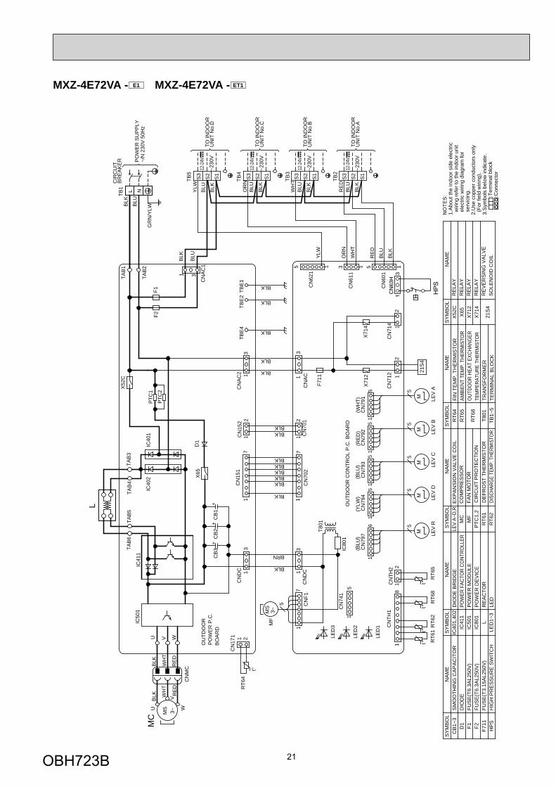
MXZ-4E72VA - E1 MXZ-4E72VA - ET1
t°21
S4
t°°t
°t
L
MS 3~
RT6
4
M LEV
RLE
V C
LEV
ALE
V B
RT6
2R
T61
X71
4X
712
F711
TO IN
DO
OR
UN
IT N
o.C
TO IN
DO
OR
UN
IT N
o.A
TO IN
DO
OR
UN
IT N
o.B
TB2
TB3
TB4
12-2
4V
~230
V
~230
V
12-2
4V
~230
V
12-2
4V
RT6
8R
T65
MM
M
MS
3~M
F
T801
BLK W
HT
RE
DR
ED
WH
T
BLK
U
V
W
MC
CB
3C
B2
CB
1B
OA
RD
PO
WE
R P
.C.
OU
TDO
OR
OU
TDO
OR
CO
NTR
OL
P.C
. BO
AR
D
F1F2
TB1
BR
EA
KE
RC
IRC
UIT
PO
WE
R S
UP
PLY
~/N
230
V 5
0Hz
LEV
D
M
TO IN
DO
OR
UN
IT N
o.D
~230
V
12-2
4V
TB5
IC80
1
5
HPS
CN63
H1
3
16
CN
797
CN
714 1
2
CN
AC
CN
712 1
2
S1
S2
S3
S1
S2
S3
S1
S2
S3
15
CN
741
D1
IC40
1IC
402
21C
N17
1
18
CN
TH1
21C
NTH
2
55
5
CN
MC
15
51
17
1
CN
792
CN
791
CN
793
15
5
71
CN
F1C
N70
21
3C
ND
C
U V W
13
1C
N15
11
7C
ND
CC
NA
C2
CN
794
51
CN
7012
112
CN
152
IC50
1IC
411
TAB
4TA
B6
TAB
5TA
B3
X52
C
3
5
CN
601
13
CN
611
11
CN
621
5
TAB
1
TAB
2
31
CN
AC
1
3TB
E4
TBE
2TB
E1
PTC
1
PTC
2
X65
L N
5
S1
S2
S3
(BLU
)B
LK
BLU
RE
D
BLK
BLU
WH
T
BLK
BLU
OR
N
BLK
BLK
BRN
BLK
BLK
(RE
D)
(WH
T)(B
LU)
(YLW
)
BLKBLKBLKBLKBLK
BLKBLK
BLK BLU R
ED
BLU
BLK
BLK
BLK
BLK
BLK
BLU
GR
N/Y
LW
WH
T
OR
N
YLW
BLU
BLK
YLW
++
+
LEV
A~D,
RM
CM
FP
TC1,
2R
T61
RT6
2
X52
CX
65X
712
X71
4
21S
4
RE
LAY
RE
LAY
RE
LAY
RE
LAY
RE
VE
RS
ING
VA
LVE
SO
LEN
OID
CO
ILD
EFR
OS
T TH
ER
MIS
TOR
FIN
TE
MP
. TH
ER
MIS
TOR
AMBI
ENT
TEM
P. T
HERM
ISTO
RO
UTDO
OR
HEAT
EXC
HANG
ERTE
MPE
RATU
RE T
HERM
ISTO
RTR
AN
SFO
RM
ER
TER
MIN
AL
BLO
CK
RT6
4R
T65
RT6
8
T801
TB1~
5
FAN
MO
TOR
CO
MP
RE
SS
OR
EX
PA
NS
ION
VA
LVE
CO
IL
DISC
HARG
E TE
MP.
THE
RMIS
TOR
SM
OO
THIN
G C
AP
AC
ITO
RD
IOD
EFU
SE
(T6.
3AL2
50V
)FU
SE
(T6.
3AL2
50V
)FU
SE
(T3.
15A
L250
V)
HIG
H P
RE
SS
UR
E S
WIT
CH
CB
1~3
D1
F1 F2 F711
HP
S
CIR
CU
IT P
RO
TEC
TIO
N
NO
TES
:1.
Abo
ut th
e in
door
sid
e el
ectri
c w
iring
refe
r to
the
indo
or u
nit
ele
ctric
wiri
ng d
iagr
am fo
r s
ervi
cing
.2.
Use
cop
per c
ondu
ctor
s on
ly (
For f
ield
wiri
ng).
3.S
ymbo
ls b
elow
indi
cate
.
:T
erm
inal
blo
ck
:C
onne
ctor
SY
MB
OL
NA
ME
SY
MB
OL
SY
MB
OL
SY
MB
OL
NA
ME
NA
ME
NA
ME
SY
MB
OL
NA
ME
DIO
DE
BR
IDG
EPO
WER
FAC
TOR
CONT
ROLL
ERP
OW
ER
MO
DU
LEP
OW
ER
DE
VIC
ER
EA
CTO
RLE
D
IC40
1,40
2IC
411
IC50
1IC
801
LLE
D1~
3
LED
3
LED
2
LED
1
t°
OBH723B
22
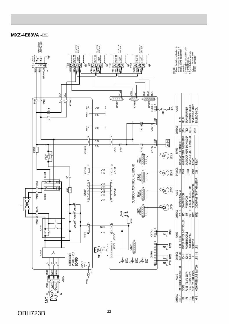
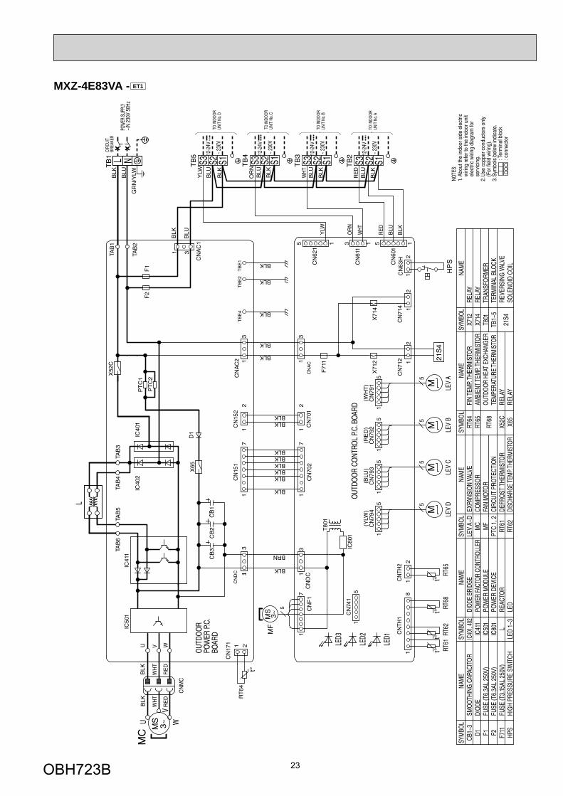
MXZ-4E83VA - E1
OBH723B
23
MXZ-4E83VA - ET1
OBH723B
24
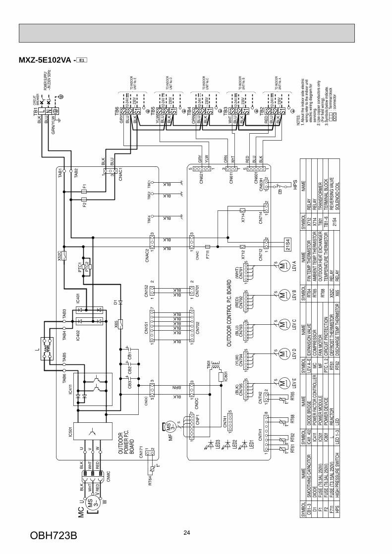
MXZ-5E102VA - E1
OBH723B
25
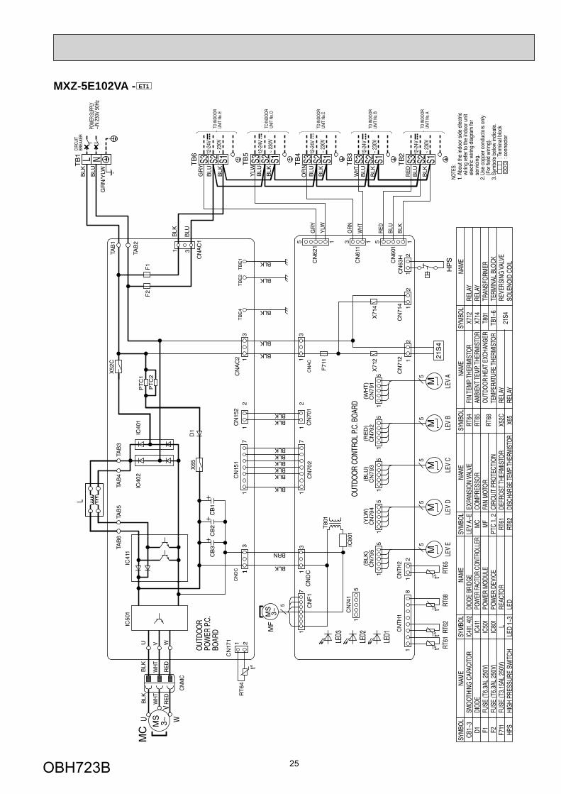
MXZ-5E102VA - ET1
OBH723B
26
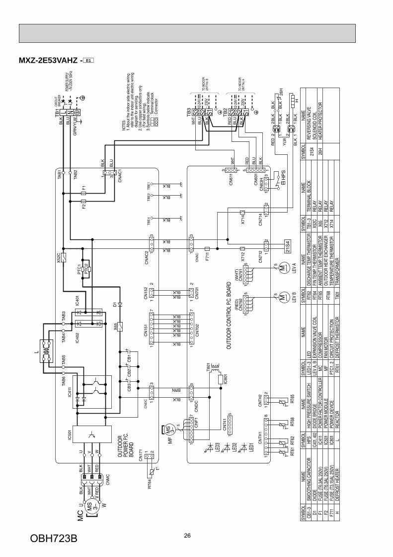
MXZ-2E53VAHZ - E1
OBH723B
27
MXZ-4E83VAHZ - E1
OBH723B
28
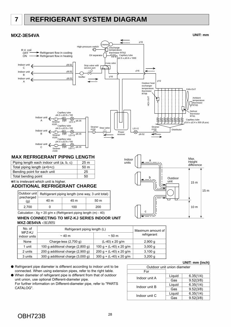
REFRIGERANT SYSTEM DIAGRAM7
Strainer#100
Powerreceiver
LEV A
LEV B
LEV C
Oil separator
Compressor
Defrost thermistorRT61
Distributor
Muffler
4-way valve
LEV E
Indoor unitC
Indoor unitB
Indoor unitA
Indoor unitA
Indoor unitB
Indoor unitC
Capillary tube
Capillary tube
Capillary tube
Capillary tube
Capillary tube
Dischargetemperaturethermistor RT62
Strainer#100
Strainer#100
Strainer#100
R.V. coil OFF ON
Refrigerant flow in coolingRefrigerant flow in heating
Ambienttemperature thermistor RT65
Outdoor heatexchangertemperaturethermistorRT68
FAN-OUT
HE
X-O
UT
Strainer#100
Stop valve withservice port
Stop valve
High-pressure switch
UNIT: mm (inch)
UNIT: mmMXZ-3E54VA
MAX REFRIGERANT PIPING LENGTH
Outdoor unit union diameterFor
Indoor unit A Liquid 6.35(1/4)Gas 9.52(3/8)
Indoor unit B Liquid 6.35(1/4)Gas 9.52(3/8)
Indoor unit C Liquid 6.35(1/4)Gas 9.52(3/8)
a
b
c
Outdoorunit
Indoorunits
15 m
10 m
15 m
Max.Heightdifference
Piping length each indoor unit (a, b, c) 25 mTotal piping length (a+b+c) 50 mBending point for each unit 25Total bending point 50It is irrelevant which unit is higher.
Refrigerant pipe diameter is different according to indoor unit to be connected. When using extension pipes, refer to the right table.
When diameter of refrigerant pipe is different from that of outdoor unit union, use optional Different-diameter pipe.
For further information on Different-diameter pipe, refer to "PARTS CATALOG".
ADDITIONAL REFRIGERANT CHARGEOutdoor unit precharged
(g)
Refrigerant piping length (one way, 3 unit total)
40 m 45 m 50 m
2,700 0 100 200
Calculation : Xg = 20 g/m x (Refrigerant piping length (m) - 40)
WHEN CONNECTING TO MFZ-KJ SERIES INDOOR UNITMXZ-3E54VA - E1 / ET1
No. ofMFZ-KJ
indoor units
Refrigerant piping length (L) Maximum amount of refrigerant~ 40 m ~ 50 m
None Charge-less (2,700 g) (L-40) x 20 g/m 2,900 g1 unit 100 g additional charge (2,800 g) 100 g + (L-40) x 20 g/m 3,000 g2 units 200 g additional charge (2,900 g) 200 g + (L-40) x 20 g/m 3,100 g3 units 300 g additional charge (3,000 g) 300 g + (L-40) x 20 g/m 3,200 g
OBH723B
29
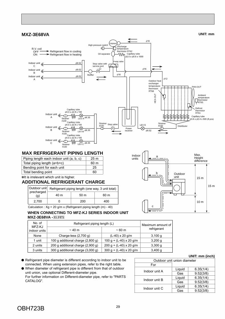
Strainer#100
Powerreceiver
LEV A
LEV B
LEV C
Oil separator
Compressor
Defrost thermistorRT61
Distributor
Muffler
4-way valve
LEV E
Indoor unitC
Indoor unitB
Indoor unitA
Indoor unitA
Indoor unitB
Indoor unitC
Capillary tube
Capillary tube
Capillary tube
Capillary tube
Capillary tube
Dischargetemperaturethermistor RT62
Strainer#100
Strainer#100
Strainer#100
R.V. coil OFF ON
Refrigerant flow in coolingRefrigerant flow in heating
Ambienttemperature thermistor RT65
Outdoor heatexchangertemperaturethermistorRT68
FAN-OUT
HE
X-O
UT
Strainer#100
Stop valve withservice port
Stop valve
High-pressure switch
UNIT: mmMXZ-3E68VA
MAX REFRIGERANT PIPING LENGTHa
b
c
Outdoorunit
Indoorunits
15 m
10 m
15 m
Max.Heightdifference
Piping length each indoor unit (a, b, c) 25 mTotal piping length (a+b+c) 60 mBending point for each unit 25Total bending point 60It is irrelevant which unit is higher.
ADDITIONAL REFRIGERANT CHARGEOutdoor unit precharged
(g)
Refrigerant piping length (one way, 3 unit total)
40 m 50 m 60 m
2,700 0 200 400
Calculation : Xg = 20 g/m x (Refrigerant piping length (m) - 40)
UNIT: mm (inch)Outdoor unit union diameter
For
Indoor unit A Liquid 6.35(1/4)Gas 9.52(3/8)
Indoor unit B Liquid 6.35(1/4)Gas 9.52(3/8)
Indoor unit C Liquid 6.35(1/4)Gas 9.52(3/8)
Refrigerant pipe diameter is different according to indoor unit to be connected. When using extension pipes, refer to the right table.
When diameter of refrigerant pipe is different from that of outdoor unit union, use optional Different-diameter pipe.
For further information on Different-diameter pipe, refer to "PARTS CATALOG".
WHEN CONNECTING TO MFZ-KJ SERIES INDOOR UNITMXZ-3E68VA - E1 / ET1
No. ofMFZ-KJ
indoor units
Refrigerant piping length (L) Maximum amount of refrigerant~ 40 m ~ 60 m
None Charge-less (2,700 g) (L-40) x 20 g/m 3,100 g1 unit 100 g additional charge (2,800 g) 100 g + (L-40) x 20 g/m 3,200 g2 units 200 g additional charge (2,900 g) 200 g + (L-40) x 20 g/m 3,300 g3 units 300 g additional charge (3,000 g) 300 g + (L-40) x 20 g/m 3,400 g
OBH723B
30
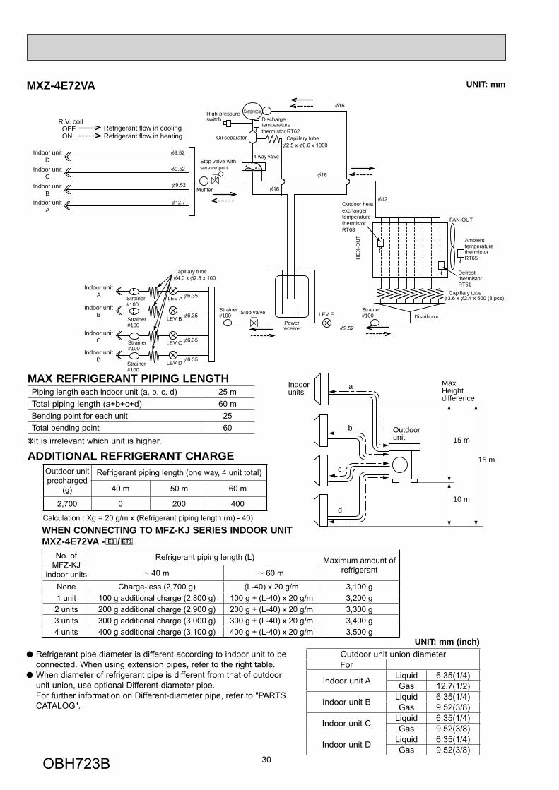
MXZ-4E72VA
Indoor unitD
Powerreceiver
LEV A
LEV B
LEV C
LEV D
Oil separator
Compressor
Muffler
4-way valve
LEV E
Indoor unitC
Indoor unitB
Indoor unitA
Indoor unitA
Indoor unitB
Indoor unitC
Indoor unitD
Capillary tube
Capillary tube
Dischargetemperaturethermistor RT62
Strainer#100
Strainer#100
Strainer#100
Strainer#100
Strainer#100
R.V. coil OFF ON
Refrigerant flow in coolingRefrigerant flow in heating
Distributor
HE
X-O
UT
Outdoor heatexchangertemperaturethermistorRT68
Defrost thermistorRT61
Capillary tube
Ambienttemperature thermistor RT65
FAN-OUT
Strainer#100
Stop valve with service port
Stop valve
High-pressureswitch
UNIT: mm
a
b
c
d
Outdoorunit
Indoorunits
15 m
10 m
15 m
Max.Heightdifference
UNIT: mm (inch)Outdoor unit union diameterFor
Indoor unit A Liquid 6.35(1/4)Gas 12.7(1/2)
Indoor unit B Liquid 6.35(1/4)Gas 9.52(3/8)
Indoor unit C Liquid 6.35(1/4)Gas 9.52(3/8)
Indoor unit D Liquid 6.35(1/4)Gas 9.52(3/8)
Refrigerant pipe diameter is different according to indoor unit to be connected. When using extension pipes, refer to the right table.
When diameter of refrigerant pipe is different from that of outdoor unit union, use optional Different-diameter pipe.
For further information on Different-diameter pipe, refer to "PARTS CATALOG".
MAX REFRIGERANT PIPING LENGTHPiping length each indoor unit (a, b, c, d) 25 mTotal piping length (a+b+c+d) 60 mBending point for each unit 25Total bending point 60It is irrelevant which unit is higher.
ADDITIONAL REFRIGERANT CHARGEOutdoor unit precharged
(g)
Refrigerant piping length (one way, 4 unit total)
40 m 50 m 60 m
2,700 0 200 400
Calculation : Xg = 20 g/m x (Refrigerant piping length (m) - 40)
WHEN CONNECTING TO MFZ-KJ SERIES INDOOR UNITMXZ-4E72VA - E1 / ET1
No. ofMFZ-KJ
indoor units
Refrigerant piping length (L) Maximum amount of refrigerant~ 40 m ~ 60 m
None Charge-less (2,700 g) (L-40) x 20 g/m 3,100 g1 unit 100 g additional charge (2,800 g) 100 g + (L-40) x 20 g/m 3,200 g2 units 200 g additional charge (2,900 g) 200 g + (L-40) x 20 g/m 3,300 g3 units 300 g additional charge (3,000 g) 300 g + (L-40) x 20 g/m 3,400 g4 units 400 g additional charge (3,100 g) 400 g + (L-40) x 20 g/m 3,500 g
OBH723B
31
a
b
c
d
Outdoorunit
Indoorunits
15 m
15 m
10 m
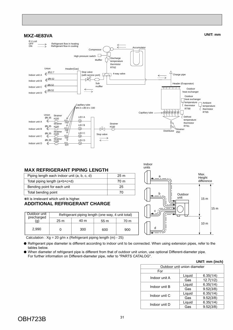
Refrigerant piping length (one way, 4 unit total)
Calculation : Xg = 20 g/m x (Refrigerant piping length (m) - 25)
Max.Heightdifference
Outdoor unit precharged
(g) 40 m
300
25 m
02,990
55 m
600
70 m
900
R.V.coilOFF Refrigerant flow in heatingON Refrigerant flow in cooling
Charge pipe
Compressor
MufflerHigh pressure switch
Ø6.35
Ø6.35
Ø9.52
Ø12.7
Accumulator
Ø6.35 LEV A
Ø9.52
Strainer#100
Strainer#100
Strainer#100
Strainer#100
Union
Union Header(Gas)
Stop valve
Header (Evaporator)
Ø6.35
Ø9.52
Submuffler
DischargetemperaturethermistorRT62
Outdoorheat exchangertemperaturethermistorRT68
AmbienttemperaturethermistorRT65
DefrosttemperaturethermistorRT61
Capillary tubeØ4.0 x Ø2.8 x 100
Indoor unit A
Indoor unit D
Indoor unit C
Indoor unit B
4-way valveStop valve(with service port)
Indoor unit A
Indoor unit D
Indoor unit C
Indoor unit BLEV B
LEV C
LEV D
Outdoorheat exchanger
Capillary tube
Distributor
Strainer#100
Strainer#50
MXZ-4E83VA UNIT: mm
Refrigerant pipe diameter is different according to indoor unit to be connected. When using extension pipes, refer to the tables below.
When diameter of refrigerant pipe is different from that of outdoor unit union, use optional Different-diameter pipe. For further information on Different-diameter pipe, refer to "PARTS CATALOG".
UNIT: mm (inch)
Piping length each indoor unit (a, b, c, d) 25 m Total piping length (a+b+c+d) 70 m Bending point for each unit 25 Total bending point 70
MAX REFRIGERANT PIPING LENGTH
Outdoor unit union diameterFor
Indoor unit A Liquid 6.35(1/4)Gas 12.7(1/2)
Indoor unit B Liquid 6.35(1/4)Gas 9.52(3/8)
Indoor unit C Liquid 6.35(1/4)Gas 9.52(3/8)
Indoor unit D Liquid 6.35(1/4)Gas 9.52(3/8)
It is irrelevant which unit is higher.ADDITIONAL REFRIGERANT CHARGE
OBH723B
32
a
b
c
d
Outdoorunit
Indoorunits
15 m
10 m
15 m
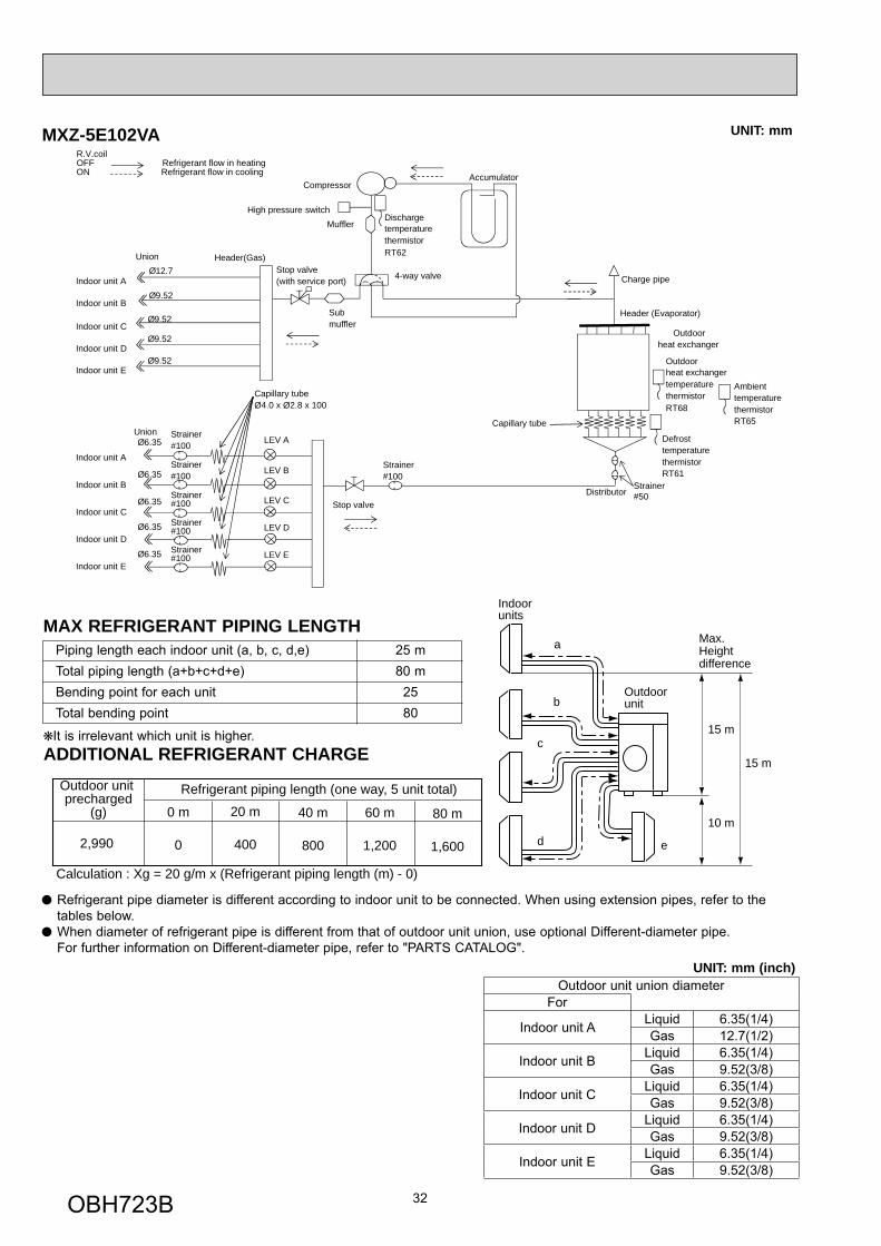
Refrigerant piping length (one way, 5 unit total)
Calculation : Xg = 20 g/m x (Refrigerant piping length (m) - 0)
e
Max.Heightdifference
Outdoor unit precharged
(g) 20 m
400
0 m
02,990
40 m
800
60 m
1,200
80 m
1,600
R.V.coilOFF Refrigerant flow in heatingON Refrigerant flow in cooling
Compressor
MufflerHigh pressure switch
Ø6.35
Ø6.35
Ø9.52
Ø12.7
Accumulator
Ø6.35 LEV A
Ø9.52
Strainer#100
Strainer#100
Strainer#100
Strainer#100
Union
Union Header(Gas)
Stop valve
Header (Evaporator)
Ø6.35
Ø9.52
Submuffler
DischargetemperaturethermistorRT62
Outdoorheat exchangertemperaturethermistorRT68
AmbienttemperaturethermistorRT65
DefrosttemperaturethermistorRT61
Capillary tubeØ4.0 x Ø2.8 x 100
Indoor unit A
Indoor unit D
Indoor unit C
Ø9.52Indoor unit E
Indoor unit B
4-way valveStop valve(with service port)
Indoor unit A
Indoor unit D
Indoor unit C
Indoor unit BLEV B
LEV C
LEV D
Strainer#100Ø6.35
Indoor unit ELEV E
Outdoorheat exchanger
Capillary tube
Distributor
Strainer#100
Strainer#50
Charge pipe
MXZ-5E102VA UNIT: mm
Refrigerant pipe diameter is different according to indoor unit to be connected. When using extension pipes, refer to the tables below.
When diameter of refrigerant pipe is different from that of outdoor unit union, use optional Different-diameter pipe. For further information on Different-diameter pipe, refer to "PARTS CATALOG".
UNIT: mm (inch)
Piping length each indoor unit (a, b, c, d,e) 25 m Total piping length (a+b+c+d+e) 80 m Bending point for each unit 25 Total bending point 80
MAX REFRIGERANT PIPING LENGTH
Outdoor unit union diameterFor
Indoor unit A Liquid 6.35(1/4)Gas 12.7(1/2)
Indoor unit B Liquid 6.35(1/4)Gas 9.52(3/8)
Indoor unit C Liquid 6.35(1/4)Gas 9.52(3/8)
Indoor unit D Liquid 6.35(1/4)Gas 9.52(3/8)
Indoor unit E Liquid 6.35(1/4)Gas 9.52(3/8)
It is irrelevant which unit is higher.ADDITIONAL REFRIGERANT CHARGE
OBH723B
33
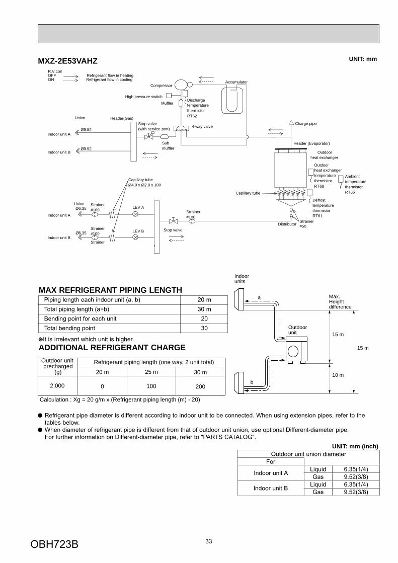
Refrigerant piping length (one way, 2 unit total)
Calculation : Xg = 20 g/m x (Refrigerant piping length (m) - 20)
a
b
Outdoorunit
Indoorunits
15 m
10 m
15 m
Max.Height difference
Outdoor unit precharged
(g) 25 m
100
20 m
02,000
30 m
200
R.V.coilOFF Refrigerant flow in heatingON Refrigerant flow in cooling
Compressor
MufflerHigh pressure switch
Ø6.35
Ø9.52
Ø9.52
Accumulator
Ø6.35 LEV AStrainer#100
Strainer#100
Strainer
Union
Union Header(Gas)
Stop valve
Header (Evaporator)Submuffler
DischargetemperaturethermistorRT62
Outdoorheat exchangertemperaturethermistorRT68
AmbienttemperaturethermistorRT65
DefrosttemperaturethermistorRT61
Capillary tubeØ4.0 x Ø2.8 x 100
Indoor unit A
Indoor unit B
4-way valveStop valve(with service port)
Indoor unit A
Indoor unit BLEV B
Outdoorheat exchanger
Capillary tube
Distributor
Strainer#100
Strainer#50
Charge pipe
MXZ-2E53VAHZ UNIT: mm
Refrigerant pipe diameter is different according to indoor unit to be connected. When using extension pipes, refer to the tables below.
When diameter of refrigerant pipe is different from that of outdoor unit union, use optional Different-diameter pipe. For further information on Different-diameter pipe, refer to "PARTS CATALOG".
UNIT: mm (inch)
Piping length each indoor unit (a, b) 20 m Total piping length (a+b) 30 m Bending point for each unit 20 Total bending point 30
MAX REFRIGERANT PIPING LENGTH
Outdoor unit union diameterFor
Indoor unit A Liquid 6.35(1/4)Gas 9.52(3/8)
Indoor unit B Liquid 6.35(1/4)Gas 9.52(3/8)
It is irrelevant which unit is higher.ADDITIONAL REFRIGERANT CHARGE
OBH723B
34
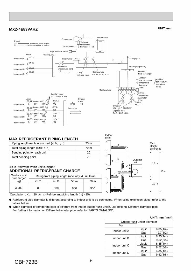
MXZ-4E83VAHZ
R.V.coilOFF Refrigerant flow in heatingON Refrigerant flow in cooling
Compressor
Oil separator
High pressure switch
Ø6.35
Ø6.35
Ø9.52
Ø12.7Indoor unit A
Accumulator
Ø6.35 LEV A
Ø9.52
2-way solenoid valve
Distributor
Strainer #100Union
Union Header(Gas)
Stop valve
Strainer
Strainer#50Strainer
#50
#100
Header(Evaporator)
Charge pipe
Capillary tube
Capillary tube
Ø2.5 x Ø0.6 x 1000
Ø4.0 x Ø3.0 x 200
Ø6.35
Dischargetemperaturethermistor RT62
Outdoorheat exchangertemperaturethermistorRT68
AmbienttemperaturethermistorRT65
DefrosttemperaturethermistorRT61
Capillary tubeØ4.0 x Ø2.8 x 100
Outdoorheat exchanger
4-way valve
Stop valve(with service port)
Indoor unit B
Indoor unit CØ9.52
Indoor unit D
Indoor unit A
Indoor unit B
Indoor unit C
Indoor unit DStrainer #100
Strainer #100
Strainer #100 LEV B
LEV D
LEV C
Capillary tube
Refrigerant piping length (one way, 4 unit total)
Calculation : Xg = 20 g/m x (Refrigerant piping length (m) - 25)
Outdoor unit precharged
(g) 40 m
300
25 m
03,900
55 m
600
70 m
900
a
b
c
d
Outdoorunit
Indoorunits
15 m
15 m
10 m
Max.Heightdifference
UNIT: mm
Refrigerant pipe diameter is different according to indoor unit to be connected. When using extension pipes, refer to the tables below.
When diameter of refrigerant pipe is different from that of outdoor unit union, use optional Different-diameter pipe. For further information on Different-diameter pipe, refer to "PARTS CATALOG".
Piping length each indoor unit (a, b, c, d) 25 m Total piping length (a+b+c+d) 70 m Bending point for each unit 25 Total bending point 70
MAX REFRIGERANT PIPING LENGTH
It is irrelevant which unit is higher.ADDITIONAL REFRIGERANT CHARGE
UNIT: mm (inch)Outdoor unit union diameter
For
Indoor unit A Liquid 6.35(1/4)Gas 12.7(1/2)
Indoor unit B Liquid 6.35(1/4)Gas 9.52(3/8)
Indoor unit C Liquid 6.35(1/4)Gas 9.52(3/8)
Indoor unit D Liquid 6.35(1/4)Gas 9.52(3/8)
OBH723B
35
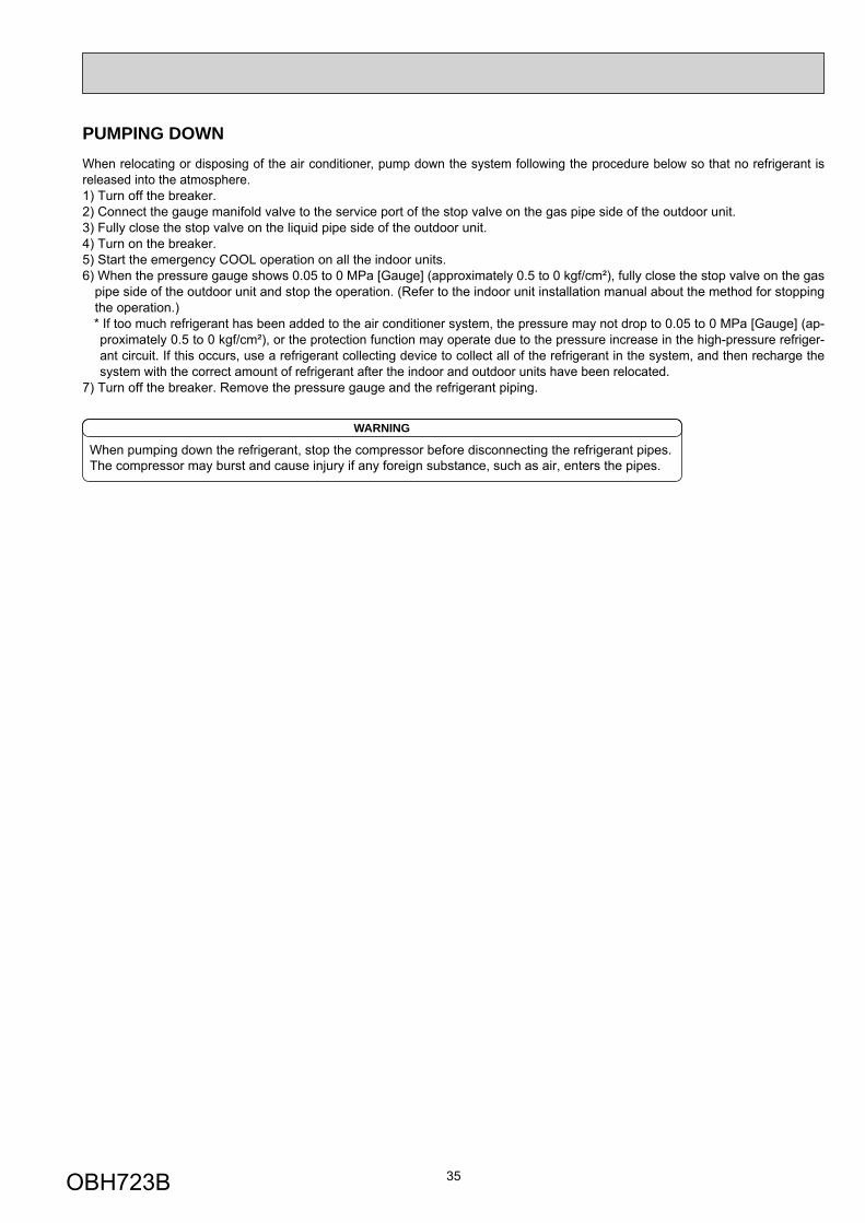
When relocating or disposing of the air conditioner, pump down the system following the procedure below so that no refrigerant is released into the atmosphere.1) Turn off the breaker.2) Connect the gauge manifold valve to the service port of the stop valve on the gas pipe side of the outdoor unit.3) Fully close the stop valve on the liquid pipe side of the outdoor unit.4) Turn on the breaker.5) Start the emergency COOL operation on all the indoor units.6) When the pressure gauge shows 0.05 to 0 MPa [Gauge] (approximately 0.5 to 0 kgf/cm²), fully close the stop valve on the gas
pipe side of the outdoor unit and stop the operation. (Refer to the indoor unit installation manual about the method for stopping the operation.) * If too much refrigerant has been added to the air conditioner system, the pressure may not drop to 0.05 to 0 MPa [Gauge] (ap-proximately 0.5 to 0 kgf/cm²), or the protection function may operate due to the pressure increase in the high-pressure refriger-ant circuit. If this occurs, use a refrigerant collecting device to collect all of the refrigerant in the system, and then recharge the system with the correct amount of refrigerant after the indoor and outdoor units have been relocated.
7) Turn off the breaker. Remove the pressure gauge and the refrigerant piping.
When pumping down the refrigerant, stop the compressor before disconnecting the refrigerant pipes. The compressor may burst and cause injury if any foreign substance, such as air, enters the pipes.
WARNING
PUMPING DOWN
OBH723B
36
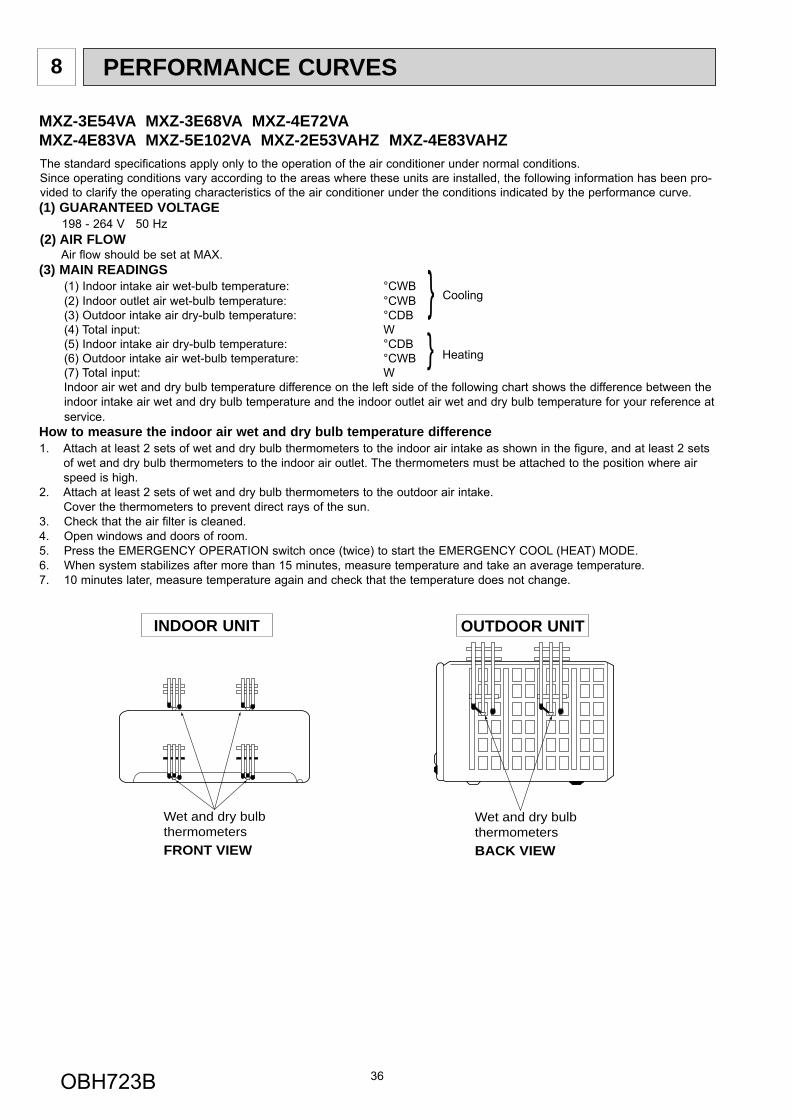
PERFORMANCE CURVES8
The standard specifications apply only to the operation of the air conditioner under normal conditions.Since operating conditions vary according to the areas where these units are installed, the following information has been pro-vided to clarify the operating characteristics of the air conditioner under the conditions indicated by the performance curve.(1) GUARANTEED VOLTAGE 198 - 264 V 50 Hz(2) AIR FLOW Air flow should be set at MAX.(3) MAIN READINGS (1) Indoor intake air wet-bulb temperature: °CWB (2) Indoor outlet air wet-bulb temperature: °CWB (3) Outdoor intake air dry-bulb temperature: °CDB (4) Total input: W (5) Indoor intake air dry-bulb temperature: °CDB (6) Outdoor intake air wet-bulb temperature: °CWB (7) Total input: W
Indoor air wet and dry bulb temperature difference on the left side of the following chart shows the difference between the indoor intake air wet and dry bulb temperature and the indoor outlet air wet and dry bulb temperature for your reference at service.
How to measure the indoor air wet and dry bulb temperature difference1. Attach at least 2 sets of wet and dry bulb thermometers to the indoor air intake as shown in the figure, and at least 2 sets
of wet and dry bulb thermometers to the indoor air outlet. The thermometers must be attached to the position where air speed is high.
2. Attach at least 2 sets of wet and dry bulb thermometers to the outdoor air intake. Cover the thermometers to prevent direct rays of the sun.3. Check that the air filter is cleaned.4. Open windows and doors of room.5. Press the EMERGENCY OPERATION switch once (twice) to start the EMERGENCY COOL (HEAT) MODE.6. When system stabilizes after more than 15 minutes, measure temperature and take an average temperature.7. 10 minutes later, measure temperature again and check that the temperature does not change.
INDOOR UNIT OUTDOOR UNIT
}}
Cooling
Heating
Wet and dry bulbthermometersBACK VIEW
Wet and dry bulbthermometersFRONT VIEW
MXZ-3E54VA MXZ-3E68VA MXZ-4E72VAMXZ-4E83VA MXZ-5E102VA MXZ-2E53VAHZ MXZ-4E83VAHZ
OBH723B
37
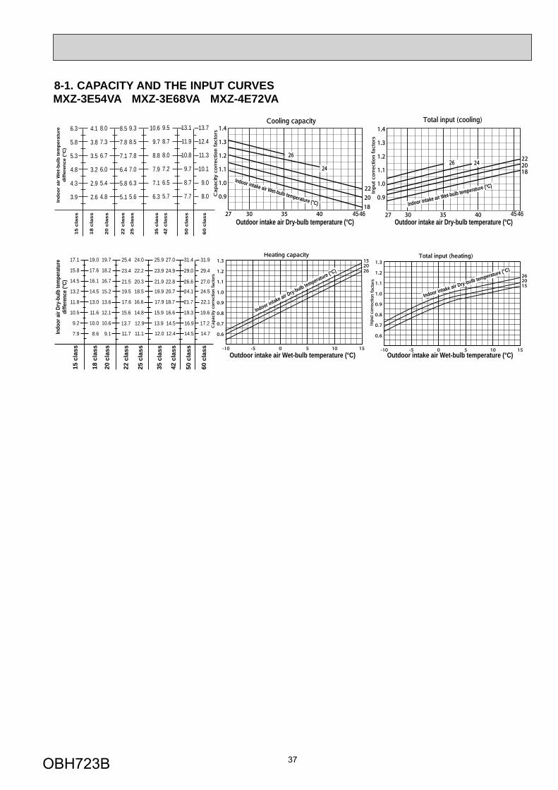
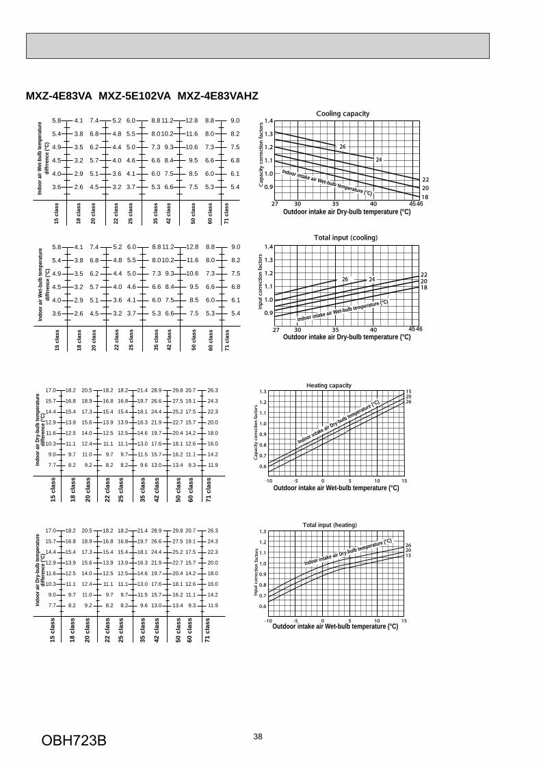
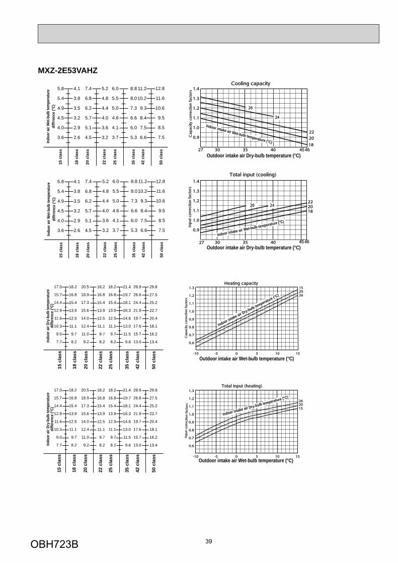
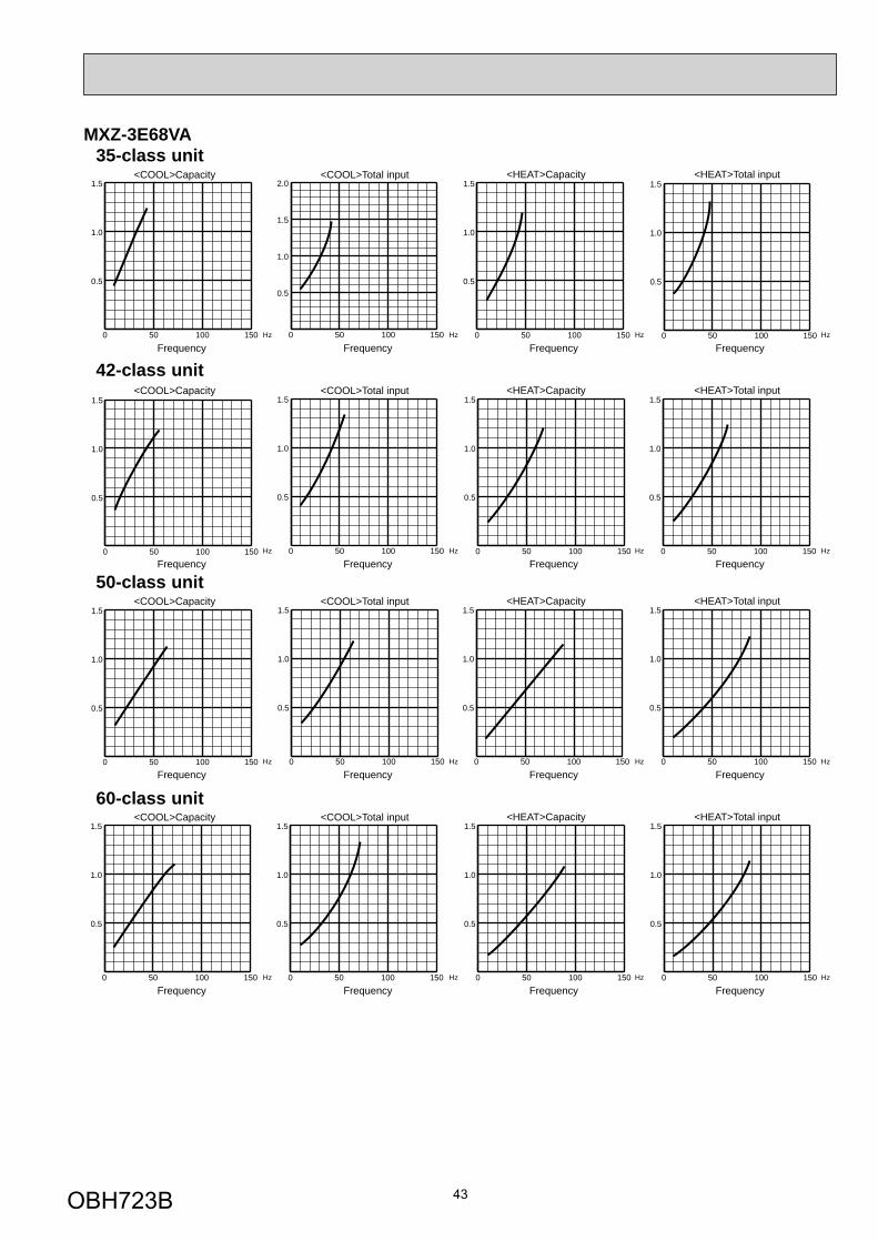
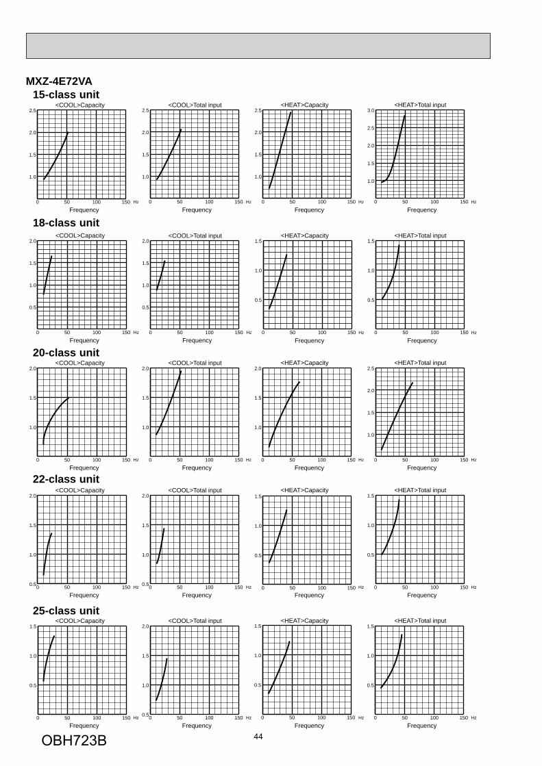
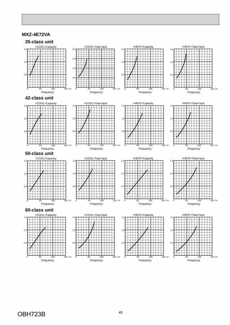
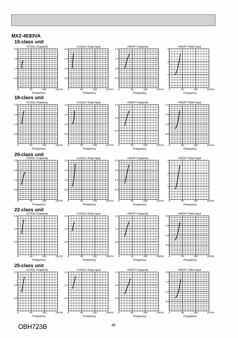
8-1. CAPACITY AND THE INPUT CURVES
Indo
or a
ir W
et-b
ulb
tem
pera
ture
diff
eren
ce (°
C)
Outdoor intake air Dry-bulb temperature (°C)46454645
Outdoor intake air Dry-bulb temperature (°C)
Indoor intake air Wet-bulb temperature (°C) Indoor intake air Wet-bulb temperature (°C)
22 c
lass
8.5
7.8
7.1
6.4
5.8
5.1
6.3
5.8
5.3
4.8
4.3
3.9
4.1
3.8
3.5
3.2
2.9
2.6
9.3
8.5
7.8
7.0
6.3
5.6
8.0
7.3
6.7
6.0
5.4
4.860
cla
ss
10.6
9.7
8.8
7.9
7.1
6.3
13.1
11.9
10.8
9.7
8.7
7.7
9.5
8.7
8.0
7.2
6.5
5.7
13.7
12.4
11.3
10.1
9.0
8.0
50 c
lass
35 c
lass
42 c
lass
25 c
lass
15 c
lass
18 c
lass
20 c
lass
MXZ-3E54VA MXZ-3E68VA MXZ-4E72VA
25.417.1
15.8
14.5
13.2
11.8
10.5
9.2
7.9
19.7
18.2
16.7
15.2
13.6
12.1
10.6
9.1
23.4
21.5
19.5
17.6
15.6
13.7
11.7
24.0
22.2
20.3
18.5
16.6
14.8
12.9
11.1
22 c
lass
25 c
lass
60 c
lass
25.9
23.9
21.9
19.9
17.9
15.9
13.9
12.0
31.4
29.0
26.6
24.1
21.7
19.3
16.9
14.5
31.9
29.4
27.0
24.5
22.1
19.6
17.2
14.7
35 c
lass
50 c
lass
27.0
24.9
22.8
20.7
18.7
16.6
14.5
12.4
42 c
lass
15 c
lass
19.0
17.6
16.1
14.5
13.0
11.6
10.0
8.6
18 c
lass
20 c
lass
Indo
or a
ir Dr
y-bu
lb te
mpe
ratu
redi
ffere
nce
(°C)
Outdoor intake air Wet-bulb temperature (°C) Outdoor intake air Wet-bulb temperature (°C)
Indoor intake air Dry-bulb temperature (°C)
Indoor intake air Dry-bulb temperature (°C)
OBH723B
38
MXZ-4E83VA MXZ-5E102VA MXZ-4E83VAHZ
Indo
or a
ir W
et-b
ulb
tem
pera
ture
diffr
renc
e (°C
)
22 c
lass
5.2
4.8
4.4
4.0
3.6
3.2
6.0
5.5
5.0
4.6
4.1
3.7
8.8
8.0
7.3
6.6
6.0
5.3
11.2
10.2
9.3
8.4
7.5
6.6
8.8
8.0
7.3
6.6
6.0
5.3
9.0
8.2
7.5
6.8
6.1
5.4
42 c
lass
35 c
lass
12.8
11.6
10.6
9.5
8.5
7.5
50 c
lass
25 c
lass
Indo
or a
ir W
et-b
ulb
tem
pera
ture
diffr
renc
e (°C
)
Outdoor intake air Dry-bulb temperature (°C)
4645
4645
Outdoor intake air Dry-bulb temperature (°C)
Indoor intake air Wet-bulb temperature (°C)
Indoor intake air Wet-bulb temperature (°C)
22 c
lass
5.2
4.8
4.4
4.0
3.6
3.2
6.0
5.5
5.0
4.6
4.1
3.7
5.8
5.4
4.9
4.5
4.0
3.6
7.4
6.8
6.2
5.7
5.1
4.5
5.8
5.4
4.9
4.5
4.0
3.6
7.4
6.8
6.2
5.7
5.1
4.5
71 c
lass
60 c
lass
8.8
8.0
7.3
6.6
6.0
5.3
11.2
10.2
9.3
8.4
7.5
6.6
8.8
8.0
7.3
6.6
6.0
5.3
9.0
8.2
7.5
6.8
6.1
5.4
42 c
lass
35 c
lass
12.8
11.6
10.6
9.5
8.5
7.550
cla
ss
25 c
lass
15 c
lass
20 c
lass
15 c
lass
4.1
3.8
3.5
3.2
2.9
2.6
4.1
3.8
3.5
3.2
2.9
2.6
18 c
lass
18 c
lass
20 c
lass
71 c
lass
60 c
lass
Indo
or a
ir Dr
y-bu
lb te
mpe
ratu
redi
ffere
nce
(°C)
Outdoor intake air Wet-bulb temperature (°C)
Indoor intake air Dry-bulb temperature (°C)
Outdoor intake air Wet-bulb temperature (°C)
Indoor intake air Dry-bulb temperature (°C)
18.2
16.8
15.4
13.9
12.5
11.1
9.7
8.2
18.2
16.8
15.4
13.9
12.5
11.1
9.7
8.2
22 c
lass
25 c
lass
21.4
19.7
18.1
16.3
14.6
13.0
11.5
9.6
28.9
26.6
24.4
21.9
19.7
17.6
15.7
13.0
20.7
19.1
17.5
15.7
14.2
12.6
11.1
9.3
26.3
24.3
22.3
20.0
18.0
16.0
14.2
11.9
35 c
lass
42 c
lass
29.8
27.5
25.2
22.7
20.4
18.1
16.2
13.4
50 c
lass
Indo
or a
ir Dr
y-bu
lb te
mpe
ratu
redi
ffere
nce
(°C)
18.2
16.8
15.4
13.9
12.5
11.1
9.7
8.2
17.0
15.7
14.4
12.9
11.6
10.3
9.0
7.7
20.5
18.9
17.3
15.6
14.0
12.4
11.0
9.2
17.0
15.7
14.4
12.9
11.6
10.3
9.0
7.7
20.5
18.9
17.3
15.6
14.0
12.4
11.0
9.2
18.2
16.8
15.4
13.9
12.5
11.1
9.7
8.2
22 c
lass
25 c
lass
60 c
lass
71 c
lass
21.4
19.7
18.1
16.3
14.6
13.0
11.5
9.6
28.9
26.6
24.4
21.9
19.7
17.6
15.7
13.0
20.7
19.1
17.5
15.7
14.2
12.6
11.1
9.3
26.3
24.3
22.3
20.0
18.0
16.0
14.2
11.9
35 c
lass
42 c
lass
29.8
27.5
25.2
22.7
20.4
18.1
16.2
13.4
50 c
lass
15 c
lass
20 c
lass
15 c
lass
18.2
16.8
15.4
13.9
12.5
11.1
9.7
8.2
18.2
16.8
15.4
13.9
12.5
11.1
9.7
8.2
18 c
lass
18 c
lass
20 c
lass
60 c
lass
71 c
lass
OBH723B
39
MXZ-2E53VAHZ
Outdoor intake air Dry-bulb temperature (°C)
4645
4645
Outdoor intake air Dry-bulb temperature (°C)
Indoor intake air Wet-bulb temperature (°C)
Indoor intake air Wet-bulb temperature (°C)
Indo
or a
ir W
et-b
ulb
tem
pera
ture
diffr
renc
e (°C
)
22 c
lass
5.2
4.8
4.4
4.0
3.6
3.2
6.0
5.5
5.0
4.6
4.1
3.7
8.8
8.0
7.3
6.6
6.0
5.3
11.2
10.2
9.3
8.4
7.5
6.6
42 c
lass
35 c
lass
12.8
11.6
10.6
9.5
8.5
7.5
50 c
lass
25 c
lass
Indo
or a
ir W
et-b
ulb
tem
pera
ture
diffr
renc
e (°C
)
22 c
lass
5.2
4.8
4.4
4.0
3.6
3.2
6.0
5.5
5.0
4.6
4.1
3.7
5.8
5.4
4.9
4.5
4.0
3.6
7.4
6.8
6.2
5.7
5.1
4.5
5.8
5.4
4.9
4.5
4.0
3.6
7.4
6.8
6.2
5.7
5.1
4.5
8.8
8.0
7.3
6.6
6.0
5.3
11.2
10.2
9.3
8.4
7.5
6.642
cla
ss
35 c
lass
12.8
11.6
10.6
9.5
8.5
7.5
50 c
lass
25 c
lass
15 c
lass
20 c
lass
15 c
lass
4.1
3.8
3.5
3.2
2.9
2.6
4.1
3.8
3.5
3.2
2.9
2.6
18 c
lass
18 c
lass
20 c
lass
Outdoor intake air Wet-bulb temperature (°C)
Indoor intake air Dry-bulb temperature (°C)
Outdoor intake air Wet-bulb temperature (°C)
Indoor intake air Dry-bulb temperature (°C)
Indo
or a
ir Dr
y-bu
lb te
mpe
ratu
redi
ffere
nce
(°C)
18.2
16.8
15.4
13.9
12.5
11.1
9.7
8.2
18.2
16.8
15.4
13.9
12.5
11.1
9.7
8.2
22 c
lass
25 c
lass
21.4
19.7
18.1
16.3
14.6
13.0
11.5
9.6
28.9
26.6
24.4
21.9
19.7
17.6
15.7
13.0
35 c
lass
42 c
lass
29.8
27.5
25.2
22.7
20.4
18.1
16.2
13.4
50 c
lass
Indo
or a
ir Dr
y-bu
lb te
mpe
ratu
redi
ffere
nce
(°C)
18.2
16.8
15.4
13.9
12.5
11.1
9.7
8.2
17.0
15.7
14.4
12.9
11.6
10.3
9.0
7.7
20.5
18.9
17.3
15.6
14.0
12.4
11.0
9.2
17.0
15.7
14.4
12.9
11.6
10.3
9.0
7.7
20.5
18.9
17.3
15.6
14.0
12.4
11.0
9.2
18.2
16.8
15.4
13.9
12.5
11.1
9.7
8.2
22 c
lass
25 c
lass
21.4
19.7
18.1
16.3
14.6
13.0
11.5
9.6
28.9
26.6
24.4
21.9
19.7
17.6
15.7
13.0
35 c
lass
42 c
lass
29.8
27.5
25.2
22.7
20.4
18.1
16.2
13.4
50 c
lass
15 c
lass
20 c
lass
15 c
lass
18.2
16.8
15.4
13.9
12.5
11.1
9.7
8.2
18.2
16.8
15.4
13.9
12.5
11.1
9.7
8.2
18 c
lass
18 c
lass
20 c
lass
OBH723B
40
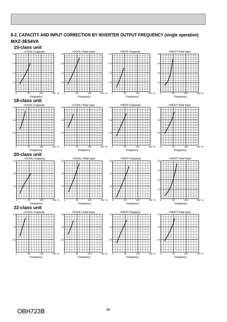
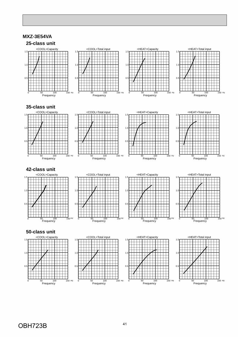
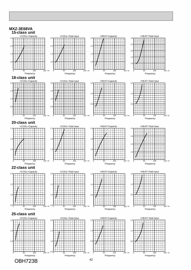
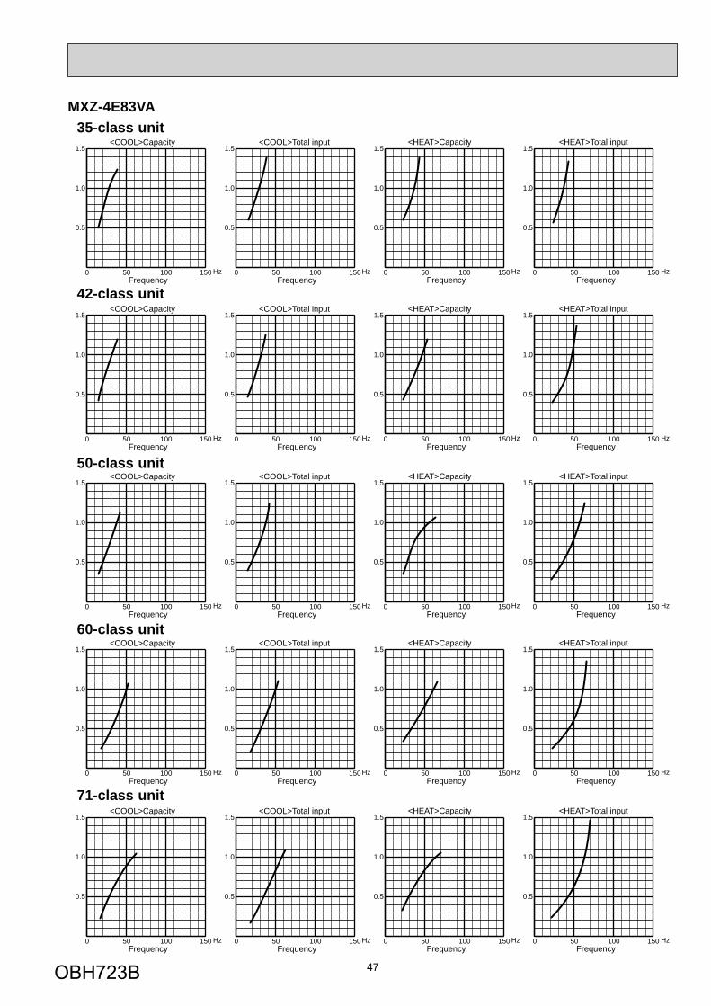
8-2. CAPACITY AND INPUT CORRECTION BY INVERTER OUTPUT FREQUENCY (single operation)
0 50 100 150
1.0
1.5
2.0
2.5
<HEAT>Capacity <HEAT>Total input
FrequencyHz
FrequencyHz0 50 100 150
1.0
1.5
2.0
2.5
0 50 100 150
1.0
1.5
2.0
2.5
<HEAT>Capacity <HEAT>Total input
FrequencyHz
FrequencyHz0 50 100 150
0.5
1.0
1.5
0 50 100 150
0.5
1.0
1.5
0 50 100 150
0.5
1.0
1.5<HEAT>Capacity
FrequencyHz 0 50 100 150
0.5
1.0
1.5<HEAT>Total input
FrequencyHz
<HEAT>Capacity <HEAT>Total input
FrequencyHz
FrequencyHz0 50 100 150
1.0
1.5
2.0
<COOL>Capacity
FrequencyHz
<COOL>Total input
FrequencyHz0 50 100 150
1.0
1.5
2.0
2.5
0 50 100 150
1.0
1.5
2.0
2.5
<COOL>Capacity
FrequencyHz
<COOL>Total input
FrequencyHz0 50 100 150
0.5
1.0
1.5
0 50 100 150
0.5
1.0
1.5
0 50 100 150
0.5
1.0
1.5<COOL>Capacity
FrequencyHz 0 50 100 150
0.5
1.0
1.5<COOL>Total input
FrequencyHz
<COOL>Capacity
FrequencyHz 0 50 100 150
1.0
1.5
2.0<COOL>Total input
FrequencyHz0 50 100 150
1.0
1.5
2.0
MXZ-3E54VA 15-class unit
22-class unit
18-class unit
20-class unit
OBH723B
41
25-class unit
0 50 100 150
0.5
1.0
1.5<COOL>Capacity
FrequencyHz 0 50 100 150
0.5
1.0
1.5<HEAT>Capacity
FrequencyHz
0 50 100 150
0.5
1.0
1.5<COOL>Capacity
FrequencyHz 0 50 100 150
0.5
1.0
1.5<HEAT>Capacity
FrequencyHz
0 50 100 150
0.5
1.0
1.5<COOL>Total input
FrequencyHz 0 50 100 150
0.5
1.0
1.5<HEAT>Total input
FrequencyHz
0 50 100 150
0.5
1.0
1.5<COOL>Total input
FrequencyHz 0 50 100 150
0.5
1.0
1.5<HEAT>Total input
FrequencyHz
<COOL>Capacity
FrequencyHz
<HEAT>Capacity
FrequencyHz
<COOL>Total input
FrequencyHz
<HEAT>Total input
FrequencyHz0 50 100 150
0.5
1.0
1.5
0 50 100 150
0.5
1.0
1.5
0 50 100 150
0.5
1.0
1.5
0 50 100 150
0.5
1.0
1.5
0 50 100 150
0.5
1.0
1.5<COOL>Capacity
FrequencyHz 0 50 100 150
0.5
1.0
1.5<HEAT>Capacity
FrequencyHz0 50 100 150
0.5
1.0
1.5<COOL>Total input
FrequencyHz 0 50 100 150
0.5
1.0
1.5<HEAT>Total input
FrequencyHz
MXZ-3E54VA
35-class unit
42-class unit
50-class unit
OBH723B
42
<COOL>Capacity
FrequencyHz
<COOL>Total input
FrequencyHz
<COOL>Capacity
FrequencyHz 0 50 100 150
1.0
1.5
2.0<COOL>Total input
FrequencyHz0 50 100 150
1.0
1.5
2.0
<COOL>Capacity
FrequencyHz 0 50 100 1500.5
1.0
1.5
2.0<COOL>Total input
FrequencyHz0 50 100 1500.5
1.0
1.5
2.0
<COOL>Capacity
FrequencyHz 0 50 100 1500.5
1.0
1.5
2.0<COOL>Total input
FrequencyHz
0 50 100 150
1.0
1.5
2.0
2.5
0 50 100 150
1.0
1.5
2.0
2.5
<COOL>Capacity
FrequencyHz
<COOL>Total input
0 50 100 150
0.5
1.0
1.5
2.0
FrequencyHz0 50 100 150
0.5
1.0
1.5
2.0
0 50 100 150
0.5
1.0
1.5
<HEAT>Capacity <HEAT>Total input
FrequencyHz
FrequencyHz
<HEAT>Capacity <HEAT>Total input
FrequencyHz
FrequencyHz0 50 100 150
1.0
1.5
2.0
<HEAT>Capacity <HEAT>Total input
FrequencyHz
FrequencyHz
<HEAT>Capacity <HEAT>Total input
FrequencyHz 0 50 100 150
0.5
1.0
1.5
FrequencyHz
0 50 100 150
1.0
1.5
2.0
2.5
0 50 100 150
1.0
1.5
2.0
2.5
0 50 100 150
1.0
1.5
2.0
2.5
3.0
<HEAT>Capacity <HEAT>Total input
FrequencyHz0 50 100 150
0.5
1.0
1.5
FrequencyHz0 50 100 150
0.5
1.0
1.5
0 50 100 150
0.5
1.0
1.5
0 50 100 150
0.5
1.0
1.5
0 50 100 150
0.5
1.0
1.5
MXZ-3E68VA 15-class unit
22-class unit
25-class unit
20-class unit
18-class unit
OBH723B
43
<COOL>Capacity
FrequencyHz
<COOL>Total input
FrequencyHz
<HEAT>Capacity <HEAT>Total input
FrequencyHz
FrequencyHz
<COOL>Capacity
FrequencyHz 0 50 100 150
0.5
1.0
1.5<COOL>Total input
FrequencyHz
<HEAT>Capacity <HEAT>Total input
FrequencyHz
FrequencyHz
<COOL>Capacity
FrequencyHz
<COOL>Total input
FrequencyHz
<HEAT>Capacity <HEAT>Total input
FrequencyHz
FrequencyHz
<COOL>Capacity
FrequencyHz
<COOL>Total input
FrequencyHz
<HEAT>Capacity <HEAT>Total input
FrequencyHz
FrequencyHz
0 50 100 150
0.5
1.0
1.5
2.0
0 50 100 150
0.5
1.0
1.5
0 50 100 150
0.5
1.0
1.5
0 50 100 150
0.5
1.0
1.5
0 50 100 150
0.5
1.0
1.5
0 50 100 150
0.5
1.0
1.5
0 50 100 150
0.5
1.0
1.5
0 50 100 150
0.5
1.0
1.5
0 50 100 150
0.5
1.0
1.5
0 50 100 150
0.5
1.0
1.5
0 50 100 150
0.5
1.0
1.5
0 50 100 150
0.5
1.0
1.5
0 50 100 150
0.5
1.0
1.5
0 50 100 150
0.5
1.0
1.5
0 50 100 150
0.5
1.0
1.5
MXZ-3E68VA 35-class unit
42-class unit
50-class unit
60-class unit
OBH723B
44
MXZ-4E72VA
<COOL>Capacity
FrequencyHz
<COOL>Total input
FrequencyHz
<HEAT>Capacity <HEAT>Total input
FrequencyHz
FrequencyHz
<COOL>Capacity
FrequencyHz 0 50 100 150
1.0
1.5
2.0<COOL>Total input
FrequencyHz
<HEAT>Capacity <HEAT>Total input
0 50 100 150
1.0
1.5
2.0
FrequencyHz
FrequencyHz0 50 100 150
1.0
1.5
2.0
<COOL>Capacity
FrequencyHz 0 50 100 1500.5
1.0
1.5
2.0<COOL>Total input
FrequencyHz
<HEAT>Capacity <HEAT>Total input
0 50 100 1500.5
1.0
1.5
2.0
FrequencyHz
FrequencyHz
<COOL>Capacity
FrequencyHz 0 50 100 1500.5
1.0
1.5
2.0<COOL>Total input
FrequencyHz
<HEAT>Capacity <HEAT>Total input
FrequencyHz 0 50 100 150
0.5
1.0
1.5
FrequencyHz
0 50 100 150
1.0
1.5
2.0
2.5
0 50 100 150
1.0
1.5
2.0
2.5
0 50 100 150
1.0
1.5
2.0
2.5
0 50 100 150
1.0
1.5
2.0
2.5
0 50 100 150
1.0
1.5
2.0
2.5
3.0
0 50 100 150
0.5
1.0
1.5
0 50 100 150
0.5
1.0
1.5
0 50 100 150
0.5
1.0
1.5
0 50 100 150
0.5
1.0
1.5
<COOL>Capacity
FrequencyHz
<COOL>Total input
0 50 100 150
0.5
1.0
1.5
2.0
FrequencyHz0 50 100 150
0.5
1.0
1.5
2.0<HEAT>Capacity <HEAT>Total input
FrequencyHz0 50 100 150
0.5
1.0
1.5
FrequencyHz0 50 100 150
0.5
1.0
1.5
15-class unit
22-class unit
25-class unit
20-class unit
18-class unit
OBH723B
45
MXZ-4E72VA
<COOL>Capacity
FrequencyHz
<COOL>Total input
FrequencyHz
<HEAT>Capacity <HEAT>Total input
FrequencyHz
FrequencyHz
<COOL>Capacity
FrequencyHz 0 50 100 150
0.5
1.0
1.5<COOL>Total input
FrequencyHz
<HEAT>Capacity <HEAT>Total input
FrequencyHz
FrequencyHz
<COOL>Capacity
FrequencyHz
<COOL>Total input
FrequencyHz
<HEAT>Capacity <HEAT>Total input
FrequencyHz
FrequencyHz
<COOL>Capacity
FrequencyHz
<COOL>Total input
FrequencyHz
<HEAT>Capacity <HEAT>Total input
FrequencyHz
FrequencyHz
0 50 100 150
0.5
1.0
1.5
2.0
0 50 100 150
0.5
1.0
1.5
0 50 100 150
0.5
1.0
1.5
0 50 100 150
0.5
1.0
1.5
0 50 100 150
0.5
1.0
1.5
0 50 100 150
0.5
1.0
1.5
0 50 100 150
0.5
1.0
1.5
0 50 100 150
0.5
1.0
1.5
0 50 100 150
0.5
1.0
1.5
0 50 100 150
0.5
1.0
1.5
0 50 100 150
0.5
1.0
1.5
0 50 100 150
0.5
1.0
1.5
0 50 100 150
0.5
1.0
1.5
0 50 100 150
0.5
1.0
1.5
0 50 100 150
0.5
1.0
1.5
35-class unit
42-class unit
50-class unit
60-class unit
OBH723B
46
MXZ-4E83VA
<COOL>Capacity
FrequencyHz
<COOL>Total input
0 50 100 150
0.5
1.0
1.5
FrequencyHz0 50 100 150
0.5
1.0
1.5
<COOL>Capacity
FrequencyHz
<COOL>Total input
0 50 100 150
0.5
1.0
1.5
FrequencyHz0 50 100 150
0.5
1.0
1.5
<COOL>Capacity
FrequencyHz
<COOL>Total input
0 50 100 150
0.5
1.0
1.5
2.0
FrequencyHz0 50 100 150
0.5
1.0
1.5
2.0
<COOL>Capacity
FrequencyHz
<COOL>Total input
0 50 100 150
0.5
1.0
1.5
2.0
FrequencyHz0 50 100 150
0.5
1.0
1.5
2.0
<COOL>Capacity
FrequencyHz
<COOL>Total input
0 50 100 150
0.5
1.0
1.5
2.0
FrequencyHz0 50 100 150
0.5
1.0
1.5
2.0
<HEAT>Capacity <HEAT>Total input
FrequencyHz0 50 100 150
0.5
1.0
1.5
FrequencyHz0 50 100 150
0.5
1.0
1.5
2.0
<HEAT>Capacity <HEAT>Total input
FrequencyHz0 50 100 150
0.5
1.0
1.5
FrequencyHz0 50 100 150
0.5
1.0
1.5
2.0
<HEAT>Capacity <HEAT>Total input
FrequencyHz0 50 100 150
0.5
1.0
1.5
2.0
FrequencyHz0 50 100 150
1
2
3
<HEAT>Capacity <HEAT>Total input
FrequencyHz0 50 100 150
0.5
1.0
1.5
FrequencyHz0 50 100 150
0.5
1.0
1.5
2.0
<HEAT>Capacity <HEAT>Total input
FrequencyHz0 50 100 150
0.5
1.0
1.5
2.0
FrequencyHz0 50 100 150
1
2
3
15-class unit
22-class unit
25-class unit
20-class unit
18-class unit
OBH723B
47
MXZ-4E83VA
<COOL>Capacity
FrequencyHz
<COOL>Total input
FrequencyHz0 50 100 150
0.5
1.0
1.5
0 50 100 150
0.5
1.0
1.5
<COOL>Capacity
FrequencyHz
<COOL>Total input
FrequencyHz0 50 100 150
0.5
1.0
1.5
0 50 100 150
0.5
1.0
1.5
<COOL>Capacity
FrequencyHz
<COOL>Total input
FrequencyHz0 50 100 150
0.5
1.0
1.5
0 50 100 150
0.5
1.0
1.5
<COOL>Capacity
FrequencyHz
<COOL>Total input
FrequencyHz0 50 100 150
0.5
1.0
1.5
0 50 100 150
0.5
1.0
1.5
<COOL>Capacity
FrequencyHz
<COOL>Total input
FrequencyHz0 50 100 150
0.5
1.0
1.5
0 50 100 150
0.5
1.0
1.5
<HEAT>Capacity
FrequencyHz
<HEAT>Total input
FrequencyHz0 50 100 150
0.5
1.0
1.5
0 50 100 150
0.5
1.0
1.5
<HEAT>Capacity
FrequencyHz
<HEAT>Total input
FrequencyHz0 50 100 150
0.5
1.0
1.5
0 50 100 150
0.5
1.0
1.5
<HEAT>Capacity
FrequencyHz
<HEAT>Total input
FrequencyHz0 50 100 150
0.5
1.0
1.5
0 50 100 150
0.5
1.0
1.5
<HEAT>Capacity
FrequencyHz
<HEAT>Total input
FrequencyHz0 50 100 150
0.5
1.0
1.5
0 50 100 150
0.5
1.0
1.5
<HEAT>Capacity
FrequencyHz
<HEAT>Total input
FrequencyHz0 50 100 150
0.5
1.0
1.5
0 50 100 150
0.5
1.0
1.5
42-class unit
50-class unit
60-class unit
71-class unit
35-class unit
OBH723B
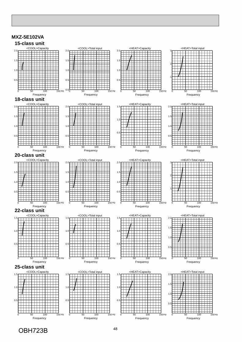
48
MXZ-5E102VA
<COOL>Capacity
FrequencyHz
<COOL>Total input
0 50 100 150
0.5
1.0
1.5
FrequencyHz0 50 100 150
0.5
1.0
1.5
<COOL>Capacity
FrequencyHz
<COOL>Total input
0 50 100 150
0.5
1.0
1.5
2.0
FrequencyHz0 50 100 150
0.5
1.0
1.5
2.0
<COOL>Capacity
FrequencyHz
<COOL>Total input
0 50 100 150
0.5
1.0
1.5
2.0
FrequencyHz0 50 100 150
0.5
1.0
1.5
2.0
<COOL>Capacity
FrequencyHz
<COOL>Total input
0 50 100 150
0.5
1.0
1.5
2.0
FrequencyHz0 50 100 1500.0
0.5
1.0
1.5
2.0
<COOL>Capacity
FrequencyHz
<COOL>Total input
0 50 100 150
0.5
1.0
1.5
FrequencyHz0 50 100 150
0.5
1.0
1.5
<HEAT>Capacity <HEAT>Total input
FrequencyHz0 50 100 150
0.5
1.0
1.5
FrequencyHz0 50 100 150
0.5
1.0
1.5
2.0
<HEAT>Capacity <HEAT>Total input
FrequencyHz0 50 100 150
0.5
1.0
1.5
2.0
FrequencyHz0 50 100 150
1
2
3
<HEAT>Capacity <HEAT>Total input
FrequencyHz0 50 100 150
0.5
1.0
1.5
FrequencyHz0 50 100 150
0.5
1.0
1.5
2.0
<HEAT>Capacity <HEAT>Total input
FrequencyHz0 50 100 150
0.5
1.0
1.5
2.0
FrequencyHz0 50 100 150
1
2
3
<HEAT>Capacity <HEAT>Total input
FrequencyHz0 50 100 150
0.5
1.0
1.5
FrequencyHz0 50 100 150
0.5
1.0
1.5
2.0
15-class unit
22-class unit
25-class unit
20-class unit
18-class unit
OBH723B
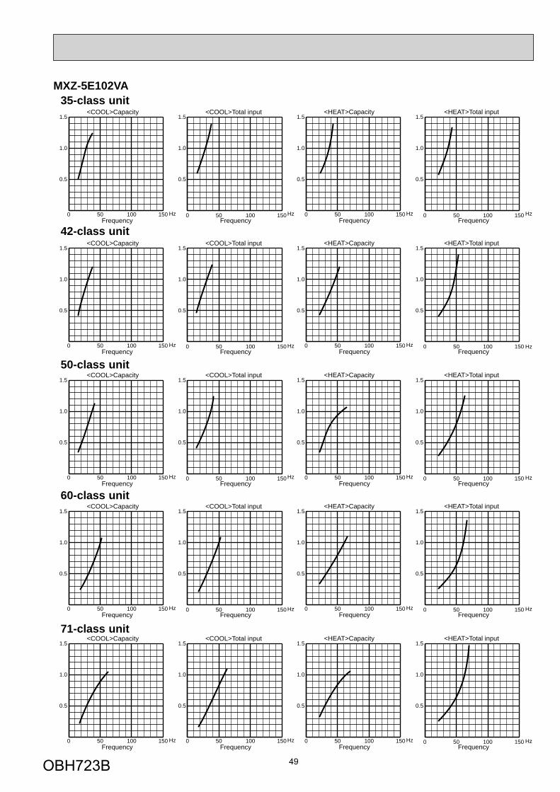
49
MXZ-5E102VA
<COOL>Capacity
FrequencyHz
<COOL>Total input
FrequencyHz0 50 100 150
0.5
1.0
1.5
0 50 100 150
0.5
1.0
1.5
<COOL>Capacity
FrequencyHz
<COOL>Total input
FrequencyHz0 50 100 150
0.5
1.0
1.5
0 50 100 150
0.5
1.0
1.5
<COOL>Capacity
FrequencyHz
<COOL>Total input
FrequencyHz0 50 100 150
0.5
1.0
1.5
0 50 100 150
0.5
1.0
1.5
<COOL>Capacity
FrequencyHz
<COOL>Total input
FrequencyHz0 50 100 150
0.5
1.0
1.5
0 50 100 150
0.5
1.0
1.5
<COOL>Capacity
FrequencyHz
<COOL>Total input
FrequencyHz0 50 100 150
0.5
1.0
1.5
0 50 100 150
0.5
1.0
1.5
<HEAT>Capacity
FrequencyHz
<HEAT>Total input
FrequencyHz0 50 100 150
0.5
1.0
1.5
0 50 100 150
0.5
1.0
1.5
<HEAT>Capacity
FrequencyHz
<HEAT>Total input
FrequencyHz0 50 100 150
0.5
1.0
1.5
0 50 100 150
0.5
1.0
1.5
<HEAT>Capacity
FrequencyHz
<HEAT>Total input
FrequencyHz0 50 100 150
0.5
1.0
1.5
0 50 100 150
0.5
1.0
1.5
<HEAT>Capacity
FrequencyHz
<HEAT>Total input
FrequencyHz0 50 100 150
0.5
1.0
1.5
0 50 100 150
0.5
1.0
1.5
<HEAT>Capacity
FrequencyHz
<HEAT>Total input
FrequencyHz0 50 100 150
0.5
1.0
1.5
0 50 100 150
0.5
1.0
1.5
42-class unit
50-class unit
60-class unit
71-class unit
35-class unit
OBH723B
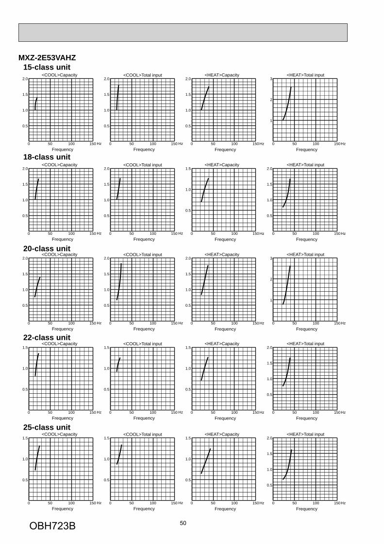
50
MXZ-2E53VAHZ
<COOL>Capacity
FrequencyHz
<COOL>Total input
0 50 100 150
0.5
1.0
1.5
FrequencyHz0 50 100 150
0.5
1.0
1.5
<COOL>Capacity
FrequencyHz
<COOL>Total input
0 50 100 150
0.5
1.0
1.5
FrequencyHz0 50 100 150
0.5
1.0
1.5
<COOL>Capacity
FrequencyHz
<COOL>Total input
0 50 100 150
0.5
1.0
1.5
2.0
FrequencyHz0 50 100 150
0.5
1.0
1.5
2.0
<COOL>Capacity
FrequencyHz
<COOL>Total input
0 50 100 150
0.5
1.0
1.5
2.0
FrequencyHz0 50 100 150
0.5
1.0
1.5
2.0
<COOL>Capacity
FrequencyHz
<COOL>Total input
0 50 100 150
0.5
1.0
1.5
2.0
FrequencyHz0 50 100 150
0.5
1.0
1.5
2.0
<HEAT>Capacity <HEAT>Total input
FrequencyHz0 50 100 150
0.5
1.0
1.5
FrequencyHz0 50 100 150
0.5
1.0
1.5
2.0
<HEAT>Capacity <HEAT>Total input
FrequencyHz0 50 100 150
0.5
1.0
1.5
FrequencyHz0 50 100 150
0.5
1.0
1.5
2.0
<HEAT>Capacity <HEAT>Total input
FrequencyHz0 50 100 150
0.5
1.0
1.5
2.0
FrequencyHz0 50 100 150
1
2
3
<HEAT>Capacity <HEAT>Total input
FrequencyHz0 50 100 150
0.5
1.0
1.5
FrequencyHz0 50 100 150
0.5
1.0
1.5
2.0
<HEAT>Capacity <HEAT>Total input
FrequencyHz0 50 100 150
0.5
1.0
1.5
2.0
FrequencyHz0 50 100 150
1
2
3
15-class unit
22-class unit
25-class unit
20-class unit
18-class unit
OBH723B
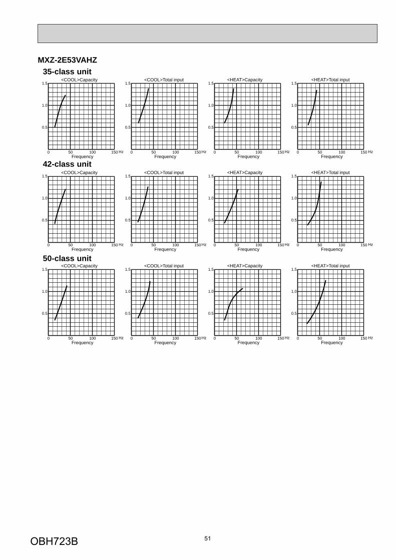
51
MXZ-2E53VAHZ
<COOL>Capacity
FrequencyHz
<COOL>Total input
FrequencyHz0 50 100 150
0.5
1.0
1.5
0 50 100 150
0.5
1.0
1.5
<COOL>Capacity
FrequencyHz
<COOL>Total input
FrequencyHz0 50 100 150
0.5
1.0
1.5
0 50 100 150
0.5
1.0
1.5
<COOL>Capacity
FrequencyHz
<COOL>Total input
FrequencyHz0 50 100 150
0.5
1.0
1.5
0 50 100 150
0.5
1.0
1.5
<HEAT>Capacity
FrequencyHz
<HEAT>Total input
FrequencyHz0 50 100 150
0.5
1.0
1.5
0 50 100 150
0.5
1.0
1.5
<HEAT>Capacity
FrequencyHz
<HEAT>Total input
FrequencyHz0 50 100 150
0.5
1.0
1.5
0 50 100 150
0.5
1.0
1.5
<HEAT>Capacity
FrequencyHz
<HEAT>Total input
FrequencyHz0 50 100 150
0.5
1.0
1.5
0 50 100 150
0.5
1.0
1.5
42-class unit
50-class unit
35-class unit
OBH723B
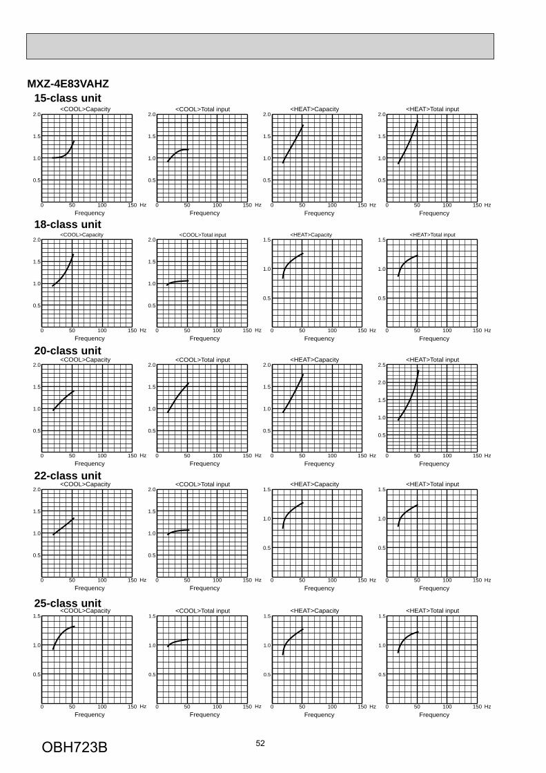
52
MXZ-4E83VAHZ
<COOL>Capacity
FrequencyHz
<COOL>Total input
0 50 100 150
0.5
1.0
1.5
2.0
FrequencyHz0 50 100 150
0.5
1.0
1.5
2.0
<COOL>Capacity
FrequencyHz
<COOL>Total input
0 50 100 150
0.5
1.0
1.5
FrequencyHz0 50 100 150
0.5
1.0
1.5
<COOL>Capacity
FrequencyHz
<COOL>Total input
0 50 100 150
0.5
1.0
1.5
2.0
FrequencyHz0 50 100 150
0.5
1.0
1.5
2.0
<COOL>Capacity
FrequencyHz
<COOL>Total input
0 50 100 150
0.5
1.0
1.5
2.0
FrequencyHz0 50 100 150
0.5
1.0
1.5
2.0
<COOL>Capacity
FrequencyHz
<COOL>Total input
0 50 100 150
0.5
1.0
1.5
2.0
FrequencyHz0 50 100 150
0.5
1.0
1.5
2.0
<HEAT>Capacity <HEAT>Total input
FrequencyHz0 50 100 150
0.5
1.0
1.5
FrequencyHz0 50 100 150
0.5
1.0
1.5
<HEAT>Capacity <HEAT>Total input
FrequencyHz0 50 100 150
0.5
1.0
1.5
FrequencyHz0 50 100 150
0.5
1.0
1.5
<HEAT>Capacity <HEAT>Total input
FrequencyHz0 50 100 150
0.5
1.0
1.5
FrequencyHz0 50 100 150
0.5
1.0
1.5
<HEAT>Capacity <HEAT>Total input
FrequencyHz0 50 100 150
0.5
1.0
1.5
2.0
FrequencyHz0 50 100 150
0.5
1.0
1.5
2.0
2.5
<HEAT>Capacity <HEAT>Total input
FrequencyHz0 50 100 150
0.5
1.0
1.5
2.0
FrequencyHz0 50 100 150
0.5
1.0
1.5
2.0
15-class unit
22-class unit
25-class unit
20-class unit
18-class unit
OBH723B
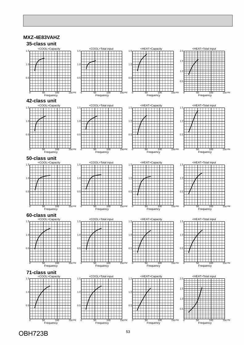
53
MXZ-4E83VAHZ
<COOL>Capacity
FrequencyHz
<HEAT>Capacity
FrequencyHz
<COOL>Total input
FrequencyHz
<HEAT>Total input
FrequencyHz0 50 100 150
0.5
1.0
1.5
0 50 100 150
0.5
1.0
1.5
0 50 100 150
0.5
1.0
1.5
0 50 100 150
0.5
1.0
1.5
<COOL>Capacity
FrequencyHz
<HEAT>Capacity
FrequencyHz
<COOL>Total input
FrequencyHz
<HEAT>Total input
FrequencyHz0 50 100 150
0.5
1.0
1.5
0 50 100 150
0.5
1.0
1.5
0 50 100 150
0.5
1.0
1.5
0 50 100 150
0.5
1.0
1.5
2.0
<COOL>Capacity
FrequencyHz
<HEAT>Capacity
FrequencyHz
<COOL>Total input
FrequencyHz
<HEAT>Total input
FrequencyHz0 50 100 150
0.5
1.0
1.5
0 50 100 150
0.5
1.0
1.5
0 50 100 150
0.5
1.0
1.5
0 50 100 150
0.5
1.0
1.5
<COOL>Capacity
FrequencyHz
<HEAT>Capacity
FrequencyHz
<COOL>Total input
FrequencyHz
<HEAT>Total input
FrequencyHz0 50 100 150
0.5
1.0
1.5
0 50 100 150
0.5
1.0
1.5
0 50 100 150
0.5
1.0
1.5
0 50 100 150
0.5
1.0
1.5
<COOL>Capacity
FrequencyHz
<HEAT>Capacity
FrequencyHz
<COOL>Total input
FrequencyHz
<HEAT>Total input
FrequencyHz0 50 100 150
0.5
1.0
1.5
0 50 100 150
0.5
1.0
1.5
0 50 100 150
0.5
1.0
1.5
0 50 100 150
0.5
1.0
1.5
2.0
42-class unit
50-class unit
60-class unit
71-class unit
35-class unit
OBH723B
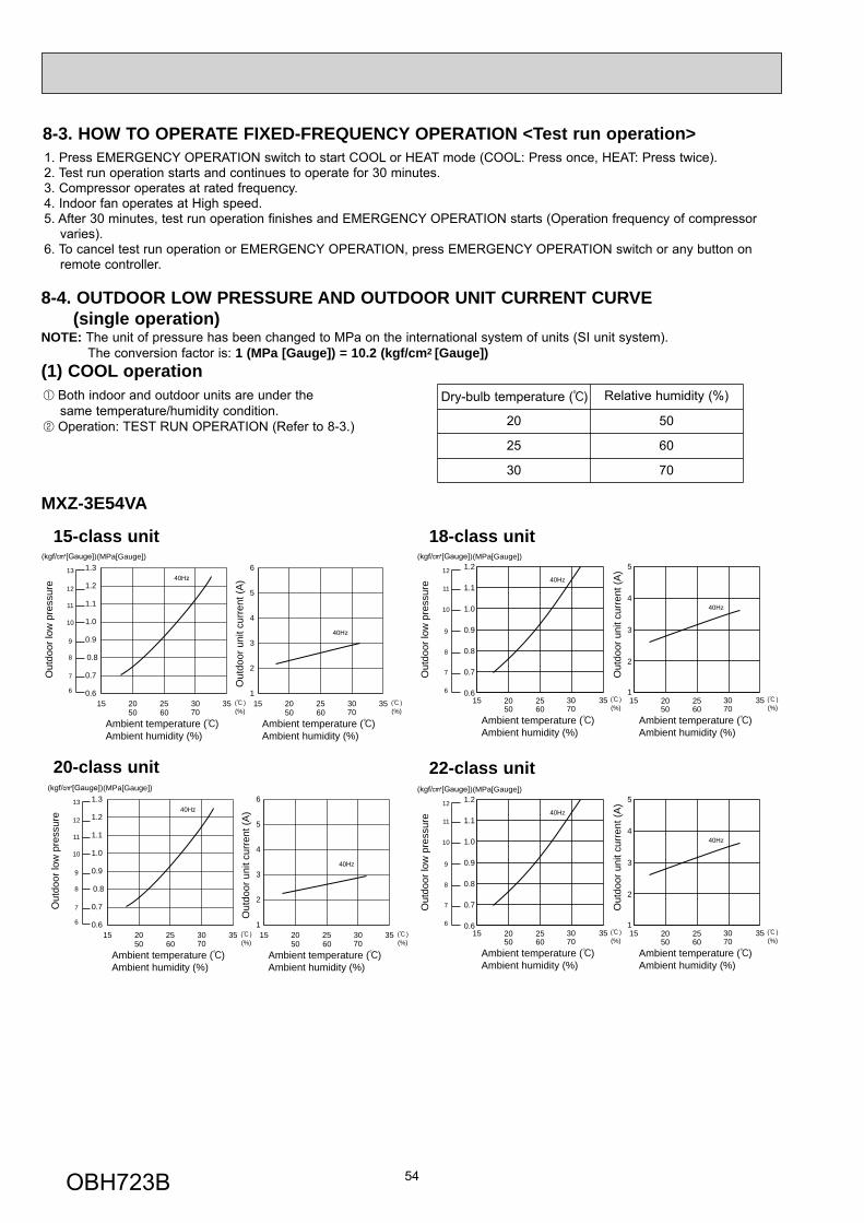
54
1. Press EMERGENCY OPERATION switch to start COOL or HEAT mode (COOL: Press once, HEAT: Press twice).2. Test run operation starts and continues to operate for 30 minutes.3. Compressor operates at rated frequency.4. Indoor fan operates at High speed.5. After 30 minutes, test run operation finishes and EMERGENCY OPERATION starts (Operation frequency of compressor varies).6. To cancel test run operation or EMERGENCY OPERATION, press EMERGENCY OPERATION switch or any button on remote controller.
8-3. HOW TO OPERATE FIXED-FREQUENCY OPERATION <Test run operation>
Both indoor and outdoor units are under the same temperature/humidity condition.
Operation: TEST RUN OPERATION (Refer to 8-3.)
Dry-bulb temperature ( ) Relative humidity (%)
20 50
25 60
30 70
8-4. OUTDOOR LOW PRESSURE AND OUTDOOR UNIT CURRENT CURVE (single operation)NOTE: The unit of pressure has been changed to MPa on the international system of units (SI unit system). The conversion factor is: 1 (MPa [Gauge]) = 10.2 (kgf/cm2 [Gauge])(1) COOL operation
15-class unit
MXZ-3E54VA
Out
door
low
pre
ssur
e
(MPa[Gauge])
Ambient temperature ( )Ambient humidity (%)
Ambient temperature ( )Ambient humidity (%)
Out
door
uni
t cur
rent
(A)
50 60 70 (%)
40Hz13
12
11
10
8
9
7
6
40Hz
15 20 25 30 350.6
0.7
0.8
0.9
1.0
1.1
1.2
1.3
50 60 70 (%)15 20 25 30 35
1
2
3
4
5
6
18-class unit
Ambient temperature ( )Ambient humidity (%)
Ambient temperature ( )Ambient humidity (%)
Out
door
low
pre
ssur
e
(MPa[Gauge])
Out
door
uni
t cur
rent
(A)
15 20 25 30 3550 60 70
0.6
0.7
0.8
0.9
1.0
1.1
1.2
(%)15 20 25 30 35
50 60 70 (%)
40Hz
1
2
3
4
5
40Hz
12
11
10
9
8
7
6
22-class unit 20-class unit
Ambient temperature ( )Ambient humidity (%)
Ambient temperature ( )Ambient humidity (%)
Out
door
low
pre
ssur
e
(MPa[Gauge])
Out
door
uni
t cur
rent
(A)
15 20 25 30 3550 60 70
0.6
0.7
0.8
0.9
1.0
1.1
1.2
(%)15 20 25 30 35
50 60 70 (%)
40Hz
1
2
3
4
5
40Hz
12
11
10
9
8
7
6
Out
door
low
pre
ssur
e
(MPa[Gauge])
Ambient temperature ( )Ambient humidity (%)
Ambient temperature ( )Ambient humidity (%)
Out
door
uni
t cur
rent
(A)
50 60 70 (%)
40Hz13
12
11
10
8
9
7
6
40Hz
15 20 25 30 350.6
0.7
0.8
0.9
1.0
1.1
1.2
1.3
50 60 70 (%)15 20 25 30 35
1
2
3
4
5
6
OBH723B
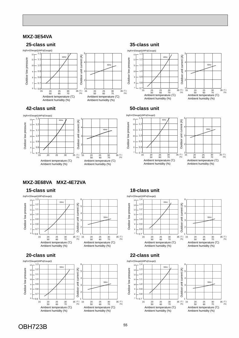
55
25-class unit
Ambient temperature ( )Ambient humidity (%)
Ambient temperature ( )Ambient humidity (%)
Out
door
low
pre
ssur
e
(MPa[Gauge])
Out
door
uni
t cur
rent
(A)
0.6
0.7
0.8
0.9
1.0
1.1
1.240Hz
1
2
3
4
5
40Hz
12
11
10
9
8
7
615 20 25 30 35
50 60 70 (%)15 20 25 30 35
50 60 70 (%)
35-class unit
Ambient temperature ( )Ambient humidity (%)
Ambient temperature ( )Ambient humidity (%)
Out
door
low
pre
ssur
e
(MPa[Gauge])
Out
door
uni
t cur
rent
(A)
0.7
0.8
0.9
1.0
1.1
1.2
1.340Hz
1
2
3
4
5
40Hz
13
12
11
10
9
8
715 20 25 30 35
50 60 70 (%)15 20 25 30 35
50 60 70 (%)
MXZ-3E54VA
42-class unit
Ambient temperature ( )Ambient humidity (%)
Ambient temperature ( )Ambient humidity (%)
Out
door
low
pre
ssur
e
(MPa[Gauge])
Out
door
uni
t cur
rent
(A)13
12
11
10
9
8
7
(%) 50 60 70 (%)15 20 25 30 35
0.7
0.8
0.9
1.0
1.1
1.2
1.340Hz
15 20 25 30 351
2
3
4
5
40Hz
50-class unit
Ambient temperature ( )Ambient humidity (%)
Ambient temperature ( )Ambient humidity (%)
Out
door
low
pre
ssur
e
(MPa[Gauge])
Out
door
uni
t cur
rent
(A)
0.7
0.8
0.9
1.0
1.1
1.2
1.340Hz
1
2
3
4
5
40Hz
13
12
11
10
9
8
715 20 25 30 35
50 60 70 (%)15 20 25 30 35
50 60 70 (%)
15-class unitMXZ-3E68VA MXZ-4E72VA
Out
door
low
pre
ssur
e
(MPa[Gauge])
Ambient temperature ( )Ambient humidity (%)
Ambient temperature ( )Ambient humidity (%)
Out
door
uni
t cur
rent
(A)
50 60 70 (%)
30Hz13
12
11
10
8
9
7
6
30Hz
15 20 25 30 350.6
0.7
0.8
0.9
1.0
1.1
1.2
1.3
50 60 70 (%)15 20 25 30 35
1
2
3
4
5
6
18-class unit
Out
door
low
pre
ssur
e
(MPa[Gauge])
Ambient temperature ( )Ambient humidity (%)
Ambient temperature ( )Ambient humidity (%)
Out
door
uni
t cur
rent
(A)
50 60 70 (%)
30Hz14
13
12
11
9
10
8
7
30Hz
15 20 25 30 350.7
0.8
0.9
1.0
1.1
1.2
1.3
1.4
50 60 70 (%)15 20 25 30 35
1
2
3
4
5
6
20-class unit
Out
door
low
pre
ssur
e
(MPa[Gauge])
Ambient temperature ( )Ambient humidity (%)
Ambient temperature ( )Ambient humidity (%)
Out
door
uni
t cur
rent
(A)
50 60 70 (%)
30Hz13
12
11
10
8
9
7
6
30Hz
15 20 25 30 350.6
0.7
0.8
0.9
1.0
1.1
1.2
1.3
50 60 70 (%)15 20 25 30 35
1
2
3
4
5
6
22-class unit
Out
door
low
pre
ssur
e
(MPa[Gauge])
Ambient temperature ( )Ambient humidity (%)
Ambient temperature ( )Ambient humidity (%)
Out
door
uni
t cur
rent
(A)
50 60 70 (%)
30Hz14
13
12
11
9
10
8
7
30Hz
15 20 25 30 350.7
0.8
0.9
1.0
1.1
1.2
1.3
1.4
50 60 70 (%)15 20 25 30 35
1
2
3
4
5
6
OBH723B
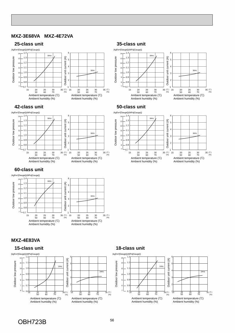
56
MXZ-3E68VA MXZ-4E72VA
42-class unit
Out
door
low
pre
ssur
e
(MPa[Gauge])
Ambient temperature ( )Ambient humidity (%)
Ambient temperature ( )Ambient humidity (%)
Out
door
uni
t cur
rent
(A)
50 60 70 (%)
30Hz14
13
12
11
9
10
8
7
30Hz
15 20 25 30 350.7
0.8
0.9
1.0
1.1
1.2
1.3
1.4
50 60 70 (%)15 20 25 30 35
1
2
3
4
5
6
50-class unitO
utdo
or lo
w p
ress
ure
(MPa[Gauge])
Ambient temperature ( )Ambient humidity (%)
Ambient temperature ( )Ambient humidity (%)
Out
door
uni
t cur
rent
(A)
50 60 70 (%)
30Hz14
13
12
11
9
10
8
7
30Hz
15 20 25 30 350.7
0.8
0.9
1.0
1.1
1.2
1.3
1.4
50 60 70 (%)15 20 25 30 35
1
2
3
4
5
6
60-class unit
Out
door
low
pre
ssur
e
(MPa[Gauge])
Ambient temperature ( )Ambient humidity (%)
Ambient temperature ( )Ambient humidity (%)
Out
door
uni
t cur
rent
(A)
50 60 70 (%)
30Hz14
13
12
11
9
10
8
7
30Hz
15 20 25 30 350.7
0.8
0.9
1.0
1.1
1.2
1.3
1.4
50 60 70 (%)15 20 25 30 35
1
2
3
4
5
6
MXZ-4E83VA 15-class unit
Out
door
low
pre
ssur
e
(MPa[Gauge])
Out
door
uni
t cur
rent
(A)
Ambient temperature ( )Ambient humidity (%)
Ambient temperature ( )Ambient humidity (%)
50 60 70 (%) 50 60 70 (%)
24Hz
24Hz
12
11
10
9
8
7
615 20 25 30 350.6
0.7
0.8
0.9
1.0
1.1
1.2
15 20 25 30 351
2
3
4
5
6
18-class unit
Out
door
low
pre
ssur
e
(MPa[Gauge])
Out
door
uni
t cur
rent
(A)
Ambient temperature ( )Ambient humidity (%)
Ambient temperature ( )Ambient humidity (%)
50 60 70 (%) 50 60 70 (%)
24Hz
24Hz
13
12
11
10
9
8
715 20 25 30 350.7
0.8
0.9
1.0
1.1
1.2
1.3
15 20 25 30 351
2
3
4
5
6
25-class unit
Out
door
low
pre
ssur
e
(MPa[Gauge])
Ambient temperature ( )Ambient humidity (%)
Ambient temperature ( )Ambient humidity (%)
Out
door
uni
t cur
rent
(A)
50 60 70 (%)
30Hz14
13
12
11
9
10
8
7
30Hz
15 20 25 30 350.7
0.8
0.9
1.0
1.1
1.2
1.3
1.4
50 60 70 (%)15 20 25 30 35
1
2
3
4
5
6
35-class unit
Out
door
low
pre
ssur
e
(MPa[Gauge])
Ambient temperature ( )Ambient humidity (%)
Ambient temperature ( )Ambient humidity (%)
Out
door
uni
t cur
rent
(A)
50 60 70 (%)
30Hz14
13
12
11
9
10
8
7
30Hz
15 20 25 30 350.7
0.8
0.9
1.0
1.1
1.2
1.3
1.4
50 60 70 (%)15 20 25 30 35
1
2
3
4
5
6
OBH723B
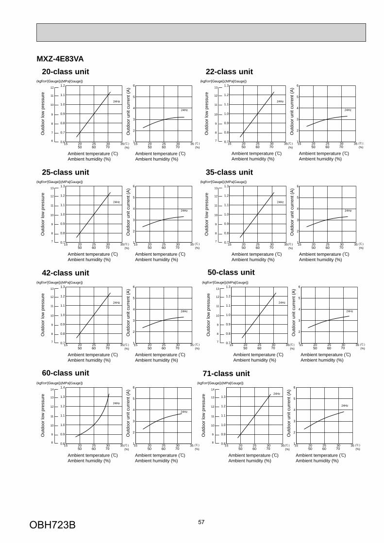
57
Out
door
low
pre
ssur
e
(MPa[Gauge])
Out
door
uni
t cur
rent
(A)
Ambient temperature ( )Ambient humidity (%)
Ambient temperature ( )Ambient humidity (%)
50 60 70 (%) 50 60 70 (%)
24Hz
24Hz
13
12
11
10
9
8
715 20 25 30 350.7
0.8
0.9
1.0
1.1
1.2
1.3
15 20 25 30 351
2
3
4
5
6
25-class unit
Out
door
low
pre
ssur
e
(MPa[Gauge])
Out
door
uni
t cur
rent
(A)
Ambient temperature ( )Ambient humidity (%)
Ambient temperature ( )Ambient humidity (%)
50 60 70 (%) 50 60 70 (%)
24Hz
24Hz
13
12
11
10
9
8
715 20 25 30 350.7
0.8
0.9
1.0
1.1
1.2
1.3
15 20 25 30 351
2
3
4
5
6
35-class unit
MXZ-4E83VA 20-class unit
Out
door
low
pre
ssur
e
(MPa[Gauge])
Out
door
uni
t cur
rent
(A)
Ambient temperature ( )Ambient humidity (%)
Ambient temperature ( )Ambient humidity (%)
50 60 70 (%) 50 60 70 (%)
24Hz
24Hz
12
11
10
9
8
7
615 20 25 30 350.6
0.7
0.8
0.9
1.0
1.1
1.2
15 20 25 30 351
2
3
4
5
6
22-class unit
Out
door
low
pre
ssur
e
(MPa[Gauge])
Out
door
uni
t cur
rent
(A)
Ambient temperature ( )Ambient humidity (%)
Ambient temperature ( )Ambient humidity (%)
50 60 70 (%) 50 60 70 (%)
24Hz
24Hz
13
12
11
10
9
8
715 20 25 30 350.7
0.8
0.9
1.0
1.1
1.2
1.3
15 20 25 30 351
2
3
4
5
6
Out
door
low
pre
ssur
e
(MPa[Gauge])
Out
door
uni
t cur
rent
(A)
Ambient temperature ( )Ambient humidity (%)
Ambient temperature ( )Ambient humidity (%)
50 60 70 (%) 50 60 70 (%)
24Hz
24Hz
13
12
11
10
9
8
715 20 25 30 350.7
0.8
0.9
1.0
1.1
1.2
1.3
15 20 25 30 351
2
3
4
5
6
42-class unit
Out
door
low
pre
ssur
e
(MPa[Gauge])
Out
door
uni
t cur
rent
(A)
Ambient temperature ( )Ambient humidity (%)
Ambient temperature ( )Ambient humidity (%)
50 60 70 (%) 50 60 70 (%)
24Hz
24Hz
14
13
12
11
10
9
815 20 25 30 350.8
0.9
1.0
1.1
1.2
1.3
1.4
15 20 25 30 351
2
3
4
5
6
60-class unit
Out
door
low
pre
ssur
e
(MPa[Gauge])
Out
door
uni
t cur
rent
(A)
Ambient temperature ( )Ambient humidity (%)
Ambient temperature ( )Ambient humidity (%)
50 60 70 (%) 50 60 70 (%)
24Hz
24Hz
13
12
11
10
9
8
715 20 25 30 350.7
0.8
0.9
1.0
1.1
1.2
1.3
15 20 25 30 351
2
3
4
5
6
50-class unit
Out
door
low
pre
ssur
e
(MPa[Gauge])
Out
door
uni
t cur
rent
(A)
Ambient temperature ( )Ambient humidity (%)
Ambient temperature ( )Ambient humidity (%)
50 60 70 (%) 50 60 70 (%)
24Hz
24Hz
14
13
12
11
10
9
815 20 25 30 350.8
0.9
1.0
1.1
1.2
1.3
15 20 25 30 351
2
3
4
5
6
71-class unit
OBH723B
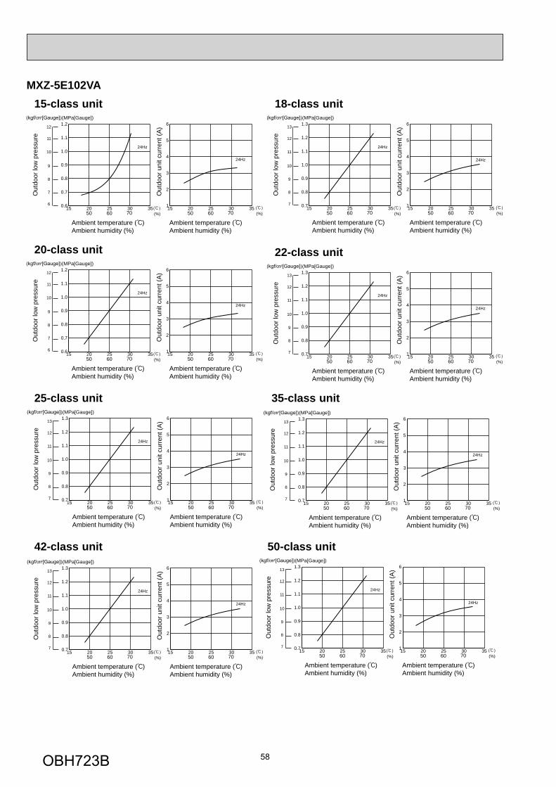
58
MXZ-5E102VA 15-class unit
Out
door
low
pre
ssur
e
(MPa[Gauge])
Out
door
uni
t cur
rent
(A)
Ambient temperature ( )Ambient humidity (%)
Ambient temperature ( )Ambient humidity (%)
50 60 70 (%) 50 60 70 (%)
24Hz
24Hz
12
11
10
9
8
7
615 20 25 30 350.6
0.7
0.8
0.9
1.0
1.1
1.2
15 20 25 30 351
2
3
4
5
6
20-class unit
Out
door
low
pre
ssur
e
(MPa[Gauge])
Out
door
uni
t cur
rent
(A)
Ambient temperature ( )Ambient humidity (%)
Ambient temperature ( )Ambient humidity (%)
50 60 70 (%) 50 60 70 (%)
24Hz
24Hz
12
11
10
9
8
7
615 20 25 30 350.6
0.7
0.8
0.9
1.0
1.1
1.2
15 20 25 30 351
2
3
4
5
6
22-class unit
Out
door
low
pre
ssur
e(MPa[Gauge])
Out
door
uni
t cur
rent
(A)
Ambient temperature ( )Ambient humidity (%)
Ambient temperature ( )Ambient humidity (%)
50 60 70 (%) 50 60 70 (%)
24Hz
24Hz
13
12
11
10
9
8
715 20 25 30 350.7
0.8
0.9
1.0
1.1
1.2
1.3
15 20 25 30 351
2
3
4
5
6
18-class unit
Out
door
low
pre
ssur
e
(MPa[Gauge])
Out
door
uni
t cur
rent
(A)
Ambient temperature ( )Ambient humidity (%)
Ambient temperature ( )Ambient humidity (%)
50 60 70 (%) 50 60 70 (%)
24Hz
24Hz
13
12
11
10
9
8
715 20 25 30 350.7
0.8
0.9
1.0
1.1
1.2
1.3
15 20 25 30 351
2
3
4
5
6
Out
door
low
pre
ssur
e
(MPa[Gauge])
Out
door
uni
t cur
rent
(A)
Ambient temperature ( )Ambient humidity (%)
Ambient temperature ( )Ambient humidity (%)
50 60 70 (%) 50 60 70 (%)
24Hz
24Hz
13
12
11
10
9
8
715 20 25 30 350.7
0.8
0.9
1.0
1.1
1.2
1.3
15 20 25 30 351
2
3
4
5
6
25-class unit
Out
door
low
pre
ssur
e
(MPa[Gauge])
Out
door
uni
t cur
rent
(A)
Ambient temperature ( )Ambient humidity (%)
Ambient temperature ( )Ambient humidity (%)
50 60 70 (%) 50 60 70 (%)
24Hz
24Hz
13
12
11
10
9
8
715 20 25 30 350.7
0.8
0.9
1.0
1.1
1.2
1.3
15 20 25 30 351
2
3
4
5
6
35-class unit
Out
door
low
pre
ssur
e
(MPa[Gauge])
Out
door
uni
t cur
rent
(A)
Ambient temperature ( )Ambient humidity (%)
Ambient temperature ( )Ambient humidity (%)
50 60 70 (%) 50 60 70 (%)
24Hz
24Hz
13
12
11
10
9
8
715 20 25 30 350.7
0.8
0.9
1.0
1.1
1.2
1.3
15 20 25 30 351
2
3
4
5
6
42-class unit
Out
door
low
pre
ssur
e
(MPa[Gauge])
Out
door
uni
t cur
rent
(A)
Ambient temperature ( )Ambient humidity (%)
Ambient temperature ( )Ambient humidity (%)
50 60 70 (%) 50 60 70 (%)
24Hz
24Hz
13
12
11
10
9
8
715 20 25 30 350.7
0.8
0.9
1.0
1.1
1.2
1.3
15 20 25 30 351
2
3
4
5
6
50-class unit
OBH723B
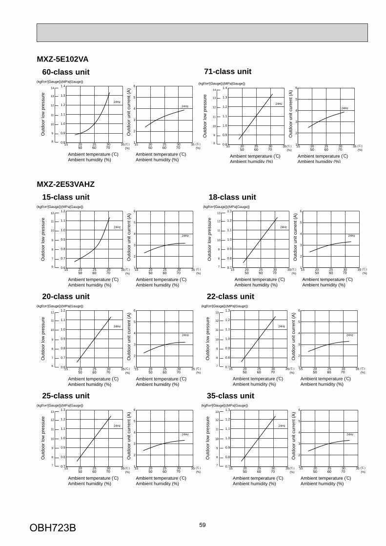
59
Out
door
low
pre
ssur
e
(MPa[Gauge])
Out
door
uni
t cur
rent
(A)
Ambient temperature ( )Ambient humidity (%)
Ambient temperature ( )Ambient humidity (%)
50 60 70 (%) 50 60 70 (%)
24Hz24Hz
14
13
12
11
10
9
815 20 25 30 350.8
0.9
1.0
1.1
1.2
1.3
1.4
15 20 25 30 351
2
3
4
5
6
60-class unitMXZ-5E102VA
Out
door
low
pre
ssur
e
(MPa[Gauge])
Out
door
uni
t cur
rent
(A)
Ambient temperature ( )Ambient humidity (%)
Ambient temperature ( )Ambient humidity (%)
50 60 70 (%) 50 60 70 (%)
24Hz24Hz
14
13
12
11
10
9
815 20 25 30 350.8
0.9
1.0
1.1
1.2
1.3
1.4
15 20 25 30 351
2
3
4
5
6
71-class unit
MXZ-2E53VAHZ 15-class unit
Out
door
low
pre
ssur
e
(MPa[Gauge])
Out
door
uni
t cur
rent
(A)
Ambient temperature ( )Ambient humidity (%)
Ambient temperature ( )Ambient humidity (%)
50 60 70 (%) 50 60 70 (%)
24Hz
24Hz
12
11
10
9
8
7
615 20 25 30 350.6
0.7
0.8
0.9
1.0
1.1
1.2
15 20 25 30 351
2
3
4
5
6
18-class unitO
utdo
or lo
w p
ress
ure
(MPa[Gauge])
Out
door
uni
t cur
rent
(A)
Ambient temperature ( )Ambient humidity (%)
Ambient temperature ( )Ambient humidity (%)
50 60 70 (%) 50 60 70 (%)
24Hz
24Hz
13
12
11
10
9
8
715 20 25 30 350.7
0.8
0.9
1.0
1.1
1.2
1.3
15 20 25 30 351
2
3
4
5
6
20-class unit
Out
door
low
pre
ssur
e
(MPa[Gauge])
Out
door
uni
t cur
rent
(A)
Ambient temperature ( )Ambient humidity (%)
Ambient temperature ( )Ambient humidity (%)
50 60 70 (%) 50 60 70 (%)
24Hz
24Hz
12
11
10
9
8
7
615 20 25 30 350.6
0.7
0.8
0.9
1.0
1.1
1.2
15 20 25 30 351
2
3
4
5
6
22-class unit
Out
door
low
pre
ssur
e
(MPa[Gauge])
Out
door
uni
t cur
rent
(A)
Ambient temperature ( )Ambient humidity (%)
Ambient temperature ( )Ambient humidity (%)
50 60 70 (%) 50 60 70 (%)
24Hz
24Hz
13
12
11
10
9
8
715 20 25 30 350.7
0.8
0.9
1.0
1.1
1.2
1.3
15 20 25 30 351
2
3
4
5
6
Out
door
low
pre
ssur
e
(MPa[Gauge])
Out
door
uni
t cur
rent
(A)
Ambient temperature ( )Ambient humidity (%)
Ambient temperature ( )Ambient humidity (%)
50 60 70 (%) 50 60 70 (%)
24Hz
24Hz
13
12
11
10
9
8
715 20 25 30 350.7
0.8
0.9
1.0
1.1
1.2
1.3
15 20 25 30 351
2
3
4
5
6
25-class unit
Out
door
low
pre
ssur
e
(MPa[Gauge])
Out
door
uni
t cur
rent
(A)
Ambient temperature ( )Ambient humidity (%)
Ambient temperature ( )Ambient humidity (%)
50 60 70 (%) 50 60 70 (%)
24Hz
24Hz
13
12
11
10
9
8
715 20 25 30 350.7
0.8
0.9
1.0
1.1
1.2
1.3
15 20 25 30 351
2
3
4
5
6
35-class unit
OBH723B
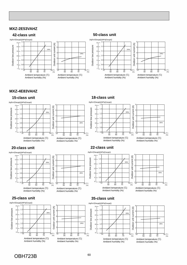
60
MXZ-2E53VAHZ
Out
door
low
pre
ssur
e
(MPa[Gauge])
Out
door
uni
t cur
rent
(A)
Ambient temperature ( )Ambient humidity (%)
Ambient temperature ( )Ambient humidity (%)
50 60 70 (%) 50 60 70 (%)
24Hz
24Hz
13
12
11
10
9
8
715 20 25 30 350.7
0.8
0.9
1.0
1.1
1.2
1.3
15 20 25 30 351
2
3
4
5
6
42-class unit
Out
door
low
pre
ssur
e
(MPa[Gauge])
Out
door
uni
t cur
rent
(A)
Ambient temperature ( )Ambient humidity (%)
Ambient temperature ( )Ambient humidity (%)
50 60 70 (%) 50 60 70 (%)
24Hz
24Hz
13
12
11
10
9
8
715 20 25 30 350.7
0.8
0.9
1.0
1.1
1.2
1.3
15 20 25 30 351
2
3
4
5
6
50-class unit
MXZ-4E83VAHZ 15-class unit
Out
door
low
pre
ssur
e
(MPa[Gauge])
Out
door
uni
t cur
rent
(A)
Ambient temperature ( )Ambient humidity (%)
Ambient temperature ( )Ambient humidity (%)
50 60 70 (%) 50 60 70 (%)
18Hz
18Hz
13
12
11
10
9
8
715 20 25 30 350.7
0.8
0.9
1.0
1.1
1.2
1.3
15 20 25 30 351
2
3
4
5
6
18-class unit
Out
door
low
pre
ssur
e
(MPa[Gauge])
Out
door
uni
t cur
rent
(A)
Ambient temperature ( )Ambient humidity (%)
Ambient temperature ( )Ambient humidity (%)
50 60 70 (%) 50 60 70 (%)
18Hz
18Hz
14
13
12
12
10
9
815 20 25 30 350.8
0.9
1.0
1.1
1.2
1.3
1.4
15 20 25 30 351
2
3
4
5
6
20-class unit
Out
door
low
pre
ssur
e
(MPa[Gauge])
Out
door
uni
t cur
rent
(A)
Ambient temperature ( )Ambient humidity (%)
Ambient temperature ( )Ambient humidity (%)
50 60 70 (%) 50 60 70 (%)
18Hz
18Hz
13
12
11
10
9
8
715 20 25 30 350.7
0.8
0.9
1.0
1.1
1.2
1.3
15 20 25 30 351
2
3
4
5
6
Out
door
low
pre
ssur
e
(MPa[Gauge])
Out
door
uni
t cur
rent
(A)
Ambient temperature ( )Ambient humidity (%)
Ambient temperature ( )Ambient humidity (%)
50 60 70 (%) 50 60 70 (%)
18Hz
18Hz
14
13
12
12
10
9
815 20 25 30 350.8
0.9
1.0
1.1
1.2
1.3
1.4
15 20 25 30 351
2
3
4
5
6
25-class unit
22-class unit
Out
door
low
pre
ssur
e
(MPa[Gauge])
Out
door
uni
t cur
rent
(A)
Ambient temperature ( )Ambient humidity (%)
Ambient temperature ( )Ambient humidity (%)
50 60 70 (%) 50 60 70 (%)
18Hz
18Hz
14
13
12
12
10
9
815 20 25 30 350.8
0.9
1.0
1.1
1.2
1.3
1.4
15 20 25 30 351
2
3
4
5
6
Out
door
low
pre
ssur
e
(MPa[Gauge])
Out
door
uni
t cur
rent
(A)
Ambient temperature ( )Ambient humidity (%)
Ambient temperature ( )Ambient humidity (%)
50 60 70 (%) 50 60 70 (%)
18Hz
18Hz
14
13
12
11
10
9
815 20 25 30 350.8
0.9
1.0
1.1
1.2
1.3
1.4
15 20 25 30 351
2
3
4
5
6
35-class unit
OBH723B
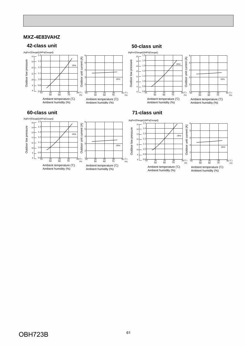
61
MXZ-4E83VAHZ
Out
door
low
pre
ssur
e
(MPa[Gauge])
Out
door
uni
t cur
rent
(A)
Ambient temperature ( )Ambient humidity (%)
Ambient temperature ( )Ambient humidity (%)
50 60 70 (%) 50 60 70 (%)
18Hz
18Hz
15
13
12
11
10
9
8
14
15 20 25 30 350.8
0.9
1.0
1.1
1.2
1.3
1.4
1.5
15 20 25 30 351
2
3
4
5
6
Out
door
low
pre
ssur
e
(MPa[Gauge])
Out
door
uni
t cur
rent
(A)
Ambient temperature ( )Ambient humidity (%)
Ambient temperature ( )Ambient humidity (%)
50 60 70 (%) 50 60 70 (%)
18Hz
18Hz
15
13
12
11
10
9
8
14
15 20 25 30 350.8
0.9
1.0
1.1
1.2
1.3
1.4
1.5
15 20 25 30 351
2
3
4
5
6
50-class unit
60-class unit
Out
door
low
pre
ssur
e
(MPa[Gauge])
Out
door
uni
t cur
rent
(A)
Ambient temperature ( )Ambient humidity (%)
Ambient temperature ( )Ambient humidity (%)
50 60 70 (%) 50 60 70 (%)
18Hz
18Hz
15
13
12
11
10
9
8
14
15 20 25 30 350.8
0.9
1.0
1.1
1.2
1.3
1.4
1.5
15 20 25 30 351
2
3
4
5
6
71-class unit
Out
door
low
pre
ssur
e
(MPa[Gauge])
Out
door
uni
t cur
rent
(A)
Ambient temperature ( )Ambient humidity (%)
Ambient temperature ( )Ambient humidity (%)
50 60 70 (%) 50 60 70 (%)
18Hz
18Hz
14
13
12
11
10
9
815 20 25 30 350.8
0.9
1.0
1.1
1.2
1.3
1.4
15 20 25 30 351
2
3
4
5
6
42-class unit
OBH723B
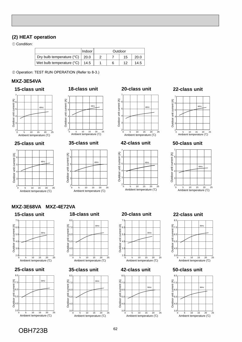
62
Condition:
Operation: TEST RUN OPERATION (Refer to 8-3.)
(2) HEAT operation
Dry bulb temperature (°C)Indoor20.014.5
21
Outdoor76
1512
20.014.5Wet bulb temperature (°C)
22-class unit
25-class unit 35-class unit
MXZ-3E54VA
42-class unit 50-class unit
15-class unit 20-class unit
50 10 15 20 252
3
4
5
6
7
Ambient temperature ( )
48Hz
Out
door
uni
t cur
rent
(A)
50 10 15 20 252
3
4
5
6
7
Ambient temperature ( )
48Hz
Out
door
uni
t cur
rent
(A)
50 10 15 20 252
3
4
5
6
7
Ambient temperature ( )
48Hz
Out
door
uni
t cur
rent
(A)
Ambient temperature ( )
Out
door
uni
t cur
rent
(A)
48Hz
0 5 10 15 20 252
3
4
5
6
7
50 10 15 20 252
3
4
5
6
7
Ambient temperature ( )
48Hz
Out
door
uni
t cur
rent
(A)
Ambient temperature ( )
Out
door
uni
t cur
rent
(A)
48Hz
0 5 10 15 20 252
3
4
5
6
7
Out
door
uni
t cur
rent
(A)
Ambient temperature ( )
48Hz
0 5 10 15 20 252
3
4
5
6
7
18-class unit
50 10 15 20 252
3
4
5
6
7
Ambient temperature ( )
48Hz
Out
door
uni
t cur
rent
(A)
22-class unit
25-class unit 35-class unit
MXZ-3E68VA MXZ-4E72VA
42-class unit 50-class unit
15-class unit 20-class unit
Ambient temperature ( )
Out
door
uni
t cur
rent
(A)
36Hz
0 5 10 15 20 252.0
3.0
4.0
5.0
6.0
7.0
Ambient temperature ( )
Out
door
uni
t cur
rent
(A)
36Hz
0 5 10 15 20 253.0
4.0
5.0
6.0
7.0
8.0
Ambient temperature ( )
Out
door
uni
t cur
rent
(A)
36Hz
0 5 10 15 20 252.0
3.0
4.0
5.0
6.0
7.0
Ambient temperature ( )
Out
door
uni
t cur
rent
(A)
36Hz
0 5 10 15 20 253.0
4.0
5.0
6.0
7.0
8.0
Ambient temperature ( )
Out
door
uni
t cur
rent
(A)
36Hz
0 5 10 15 20 253.0
4.0
5.0
6.0
7.0
8.0
Ambient temperature ( )
Out
door
uni
t cur
rent
(A)
36Hz
0 5 10 15 20 253.0
4.0
5.0
6.0
7.0
8.0
Ambient temperature ( )
Out
door
uni
t cur
rent
(A)
36Hz
0 5 10 15 20 253.0
4.0
5.0
6.0
7.0
8.0
18-class unit
Ambient temperature ( )
Out
door
uni
t cur
rent
(A)
36Hz
0 5 10 15 20 253.0
4.0
5.0
6.0
7.0
8.0
OBH723B
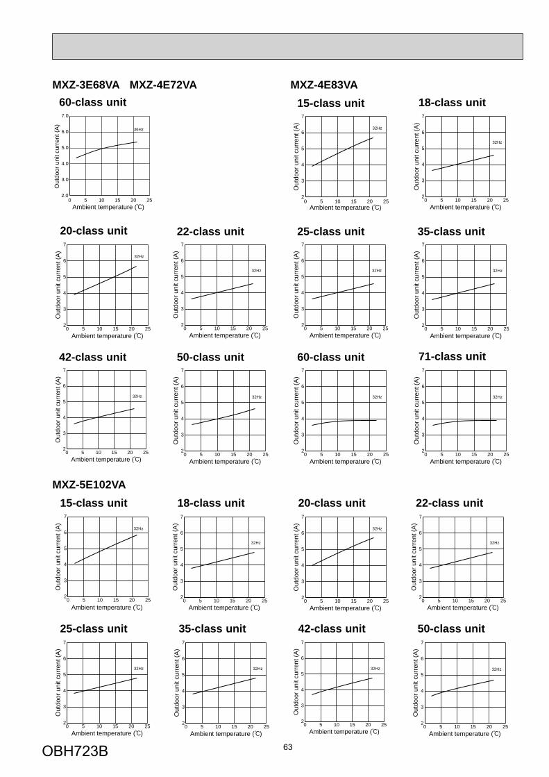
63
60-class unit
Ambient temperature ( )
Out
door
uni
t cur
rent
(A)
36Hz
0 5 10 15 20 252.0
3.0
4.0
5.0
6.0
7.0
35-class unit
0 5 10 15 20 252
3
4
5
6
7
Ambient temperature ( )
32Hz
Out
door
uni
t cur
rent
(A)
42-class unit
0 5 10 15 20 252
3
4
5
6
7
Ambient temperature ( )
32Hz
Out
door
uni
t cur
rent
(A)
50-class unit
0 5 10 15 20 252
3
4
5
6
7
Ambient temperature ( )
32Hz
Out
door
uni
t cur
rent
(A)
0 5 10 15 20 252
3
4
5
6
7
Ambient temperature ( )
32Hz
Out
door
uni
t cur
rent
(A)
60-class unit
0 5 10 15 20 252
3
4
5
6
7
Ambient temperature ( )
32Hz
Out
door
uni
t cur
rent
(A)
22-class unit 25-class unit
0 5 10 15 20 252
3
4
5
6
7
Ambient temperature ( )
32Hz
Out
door
uni
t cur
rent
(A)
MXZ-4E83VA 15-class unit
20-class unit
0 5 10 15 20 252
3
4
5
6
7
Ambient temperature ( )
32Hz
Out
door
uni
t cur
rent
(A)
0 5 10 15 20 252
3
4
5
6
7
Ambient temperature ( )
32Hz
Out
door
uni
t cur
rent
(A)
71-class unit
0 5 10 15 20 252
3
4
5
6
7
Ambient temperature ( )
32Hz
Out
door
uni
t cur
rent
(A)
18-class unit
0 5 10 15 20 252
3
4
5
6
7
Ambient temperature ( )
32Hz
Out
door
uni
t cur
rent
(A)
MXZ-5E102VA 15-class unit
0 5 10 15 20 252
3
4
5
6
7
Ambient temperature ( )
32Hz
Out
door
uni
t cur
rent
(A)
18-class unit
0 5 10 15 20 252
3
4
5
6
7
Ambient temperature ( )
32Hz
Out
door
uni
t cur
rent
(A)
0 5 10 15 20 252
3
4
5
6
7
Ambient temperature ( )
32Hz
Out
door
uni
t cur
rent
(A)
22-class unit 20-class unit
0 5 10 15 20 252
3
4
5
6
7
Ambient temperature ( )
32Hz
Out
door
uni
t cur
rent
(A)
25-class unit
0 5 10 15 20 252
3
4
5
6
7
Ambient temperature ( )
32Hz
Out
door
uni
t cur
rent
(A)
35-class unit
0 5 10 15 20 252
3
4
5
6
7
Ambient temperature ( )
32Hz
Out
door
uni
t cur
rent
(A)
MXZ-3E68VA MXZ-4E72VA
50-class unit
0 5 10 15 20 252
3
4
5
6
7
Ambient temperature ( )
32Hz
Out
door
uni
t cur
rent
(A)
42-class unit
0 5 10 15 20 252
3
4
5
6
7
Ambient temperature ( )
32Hz
Out
door
uni
t cur
rent
(A)
OBH723B

64
0 5 10 15 20 252
3
4
5
6
7
Ambient temperature ( )
32Hz
Out
door
uni
t cur
rent
(A)
60-class unit 71-class unit
0 5 10 15 20 252
3
4
5
6
7
Ambient temperature ( )
32Hz
Out
door
uni
t cur
rent
(A)
MXZ-5E102VA
35-class unit
0 5 10 15 20 252
3
4
5
6
7
Ambient temperature ( )
32Hz
Out
door
uni
t cur
rent
(A)
42-class unit
0 5 10 15 20 252
3
4
5
6
7
Ambient temperature ( )
32Hz
Out
door
uni
t cur
rent
(A)
50-class unit
0 5 10 15 20 252
3
4
5
6
7
Ambient temperature ( )
32Hz
Out
door
uni
t cur
rent
(A)
0 5 10 15 20 252
3
4
5
6
7
Ambient temperature ( )
32Hz
Out
door
uni
t cur
rent
(A)
22-class unit 25-class unit
0 5 10 15 20 252
3
4
5
6
7
Ambient temperature ( )
32HzO
utdo
or u
nit c
urre
nt (A
)
MXZ-2E53VAHZ 15-class unit
20-class unit
0 5 10 15 20 252
3
4
5
6
7
Ambient temperature ( )
32Hz
Out
door
uni
t cur
rent
(A)
0 5 10 15 20 252
3
4
5
6
7
Ambient temperature ( )
32Hz
Out
door
uni
t cur
rent
(A)
18-class unit
0 5 10 15 20 252
3
4
5
6
7
Ambient temperature ( )
32Hz
Out
door
uni
t cur
rent
(A)
MXZ-4E83VAHZ 15-class unit
0 5 10 15 20 252
3
4
5
6
7
Ambient temperature ( )
20Hz
Out
door
uni
t cur
rent
(A)
18-class unit
0 5 10 15 20 252
3
4
5
6
7
Ambient temperature ( )
20Hz
Out
door
uni
t cur
rent
(A)
0 5 10 15 20 252
3
4
5
6
7
Ambient temperature ( )
20Hz
Out
door
uni
t cur
rent
(A)
22-class unit 20-class unit
0 5 10 15 20 252
3
4
5
6
7
Ambient temperature ( )
20Hz
Out
door
uni
t cur
rent
(A)
25-class unit
0 5 10 15 20 252
3
4
5
6
7
Ambient temperature ( )
20Hz
Out
door
uni
t cur
rent
(A)
35-class unit
0 5 10 15 20 252
3
4
5
6
7
Ambient temperature ( )
20Hz
Out
door
uni
t cur
rent
(A)
50-class unit
0 5 10 15 20 252
3
4
5
6
7
Ambient temperature ( )
20Hz
Out
door
uni
t cur
rent
(A)
42-class unit
0 5 10 15 20 252
3
4
5
6
7
Ambient temperature ( )
20Hz
Out
door
uni
t cur
rent
(A)
0 5 10 15 20 252
3
4
5
6
7
Ambient temperature ( )
20Hz
Out
door
uni
t cur
rent
(A)
60-class unit 71-class unit
0 5 10 15 20 252
3
4
5
6
7
Ambient temperature ( )
20Hz
Out
door
uni
t cur
rent
(A)
OBH723B
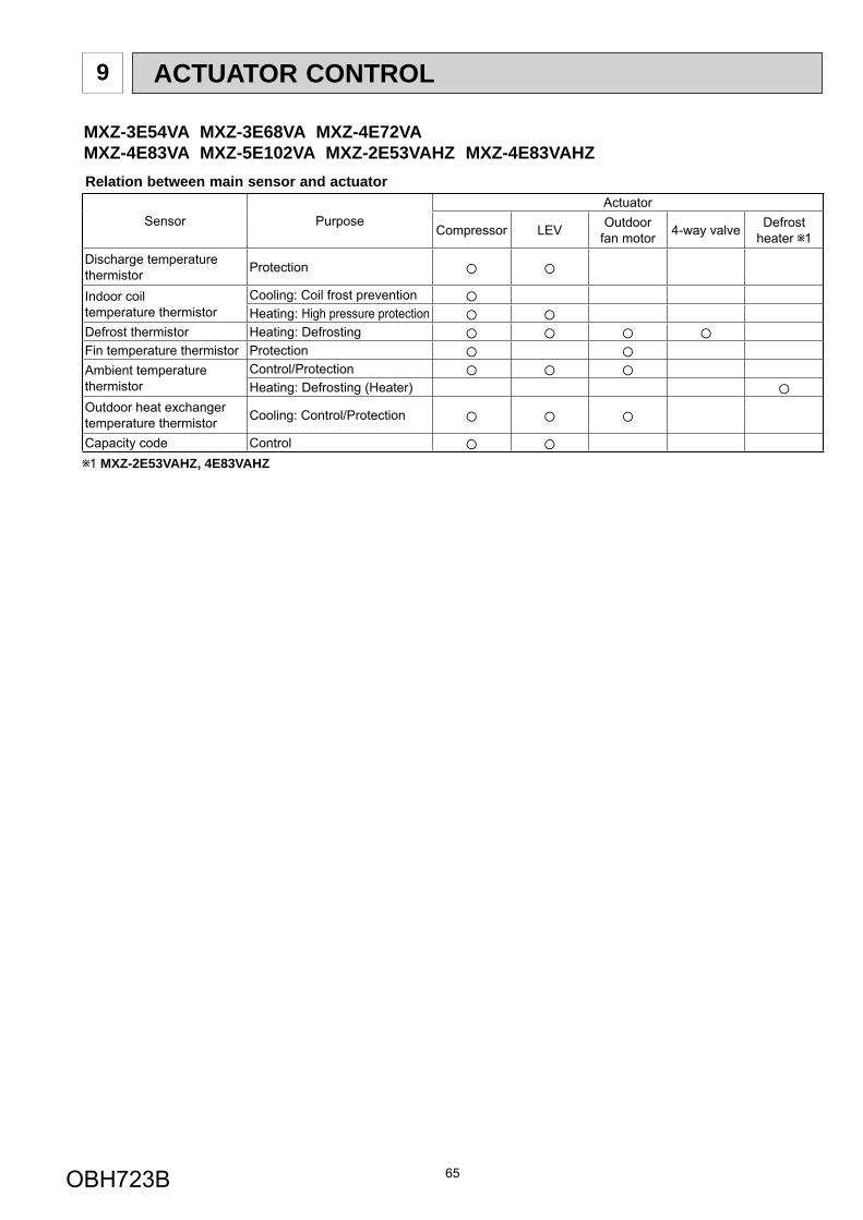
65
ACTUATOR CONTROL9
Relation between main sensor and actuator
Sensor PurposeActuator
Compressor LEV Outdoorfan motor 4-way valve Defrost
heater 1Discharge temperature thermistor Protection
Indoor coil temperature thermistor
Cooling: Coil frost preventionHeating: High pressure protection
Defrost thermistor Heating: DefrostingFin temperature thermistor ProtectionAmbient temperature thermistor
Control/ProtectionHeating: Defrosting (Heater)
Outdoor heat exchanger temperature thermistor Cooling: Control/Protection
Capacity code Control1 MXZ-2E53VAHZ, 4E83VAHZ
MXZ-3E54VA MXZ-3E68VA MXZ-4E72VAMXZ-4E83VA MXZ-5E102VA MXZ-2E53VAHZ MXZ-4E83VAHZ
OBH723B
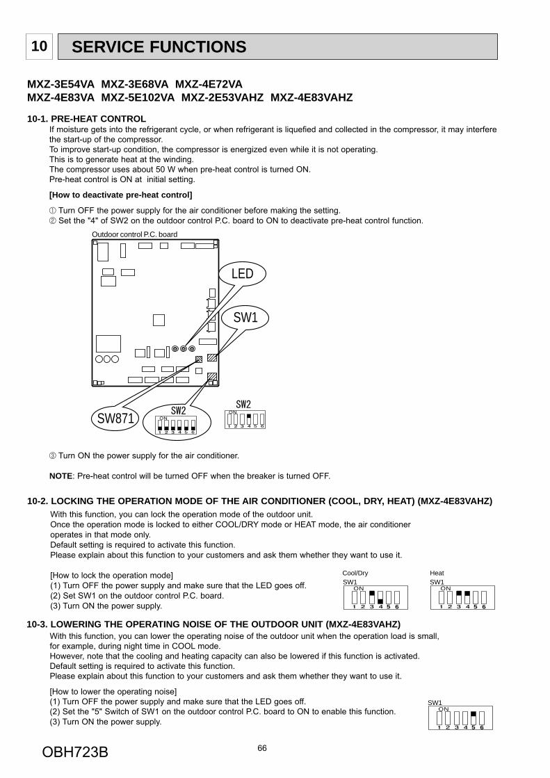
66
SERVICE FUNCTIONS10
10-1. PRE-HEAT CONTROLIf moisture gets into the refrigerant cycle, or when refrigerant is liquefied and collected in the compressor, it may interfere the start-up of the compressor.To improve start-up condition, the compressor is energized even while it is not operating. This is to generate heat at the winding.The compressor uses about 50 W when pre-heat control is turned ON.Pre-heat control is ON at initial setting.
[How to deactivate pre-heat control]
Turn OFF the power supply for the air conditioner before making the setting. Set the "4" of SW2 on the outdoor control P.C. board to ON to deactivate pre-heat control function.
Turn ON the power supply for the air conditioner.
NOTE: Pre-heat control will be turned OFF when the breaker is turned OFF.
Outdoor control P.C. board
SW871
LED
SW1
With this function, you can lock the operation mode of the outdoor unit. Once the operation mode is locked to either COOL/DRY mode or HEAT mode, the air conditioner operates in that mode only.Default setting is required to activate this function. Please explain about this function to your customers and ask them whether they want to use it.
[How to lock the operation mode](1) Turn OFF the power supply and make sure that the LED goes off. (2) Set SW1 on the outdoor control P.C. board.(3) Turn ON the power supply.
10-2. LOCKING THE OPERATION MODE OF THE AIR CONDITIONER (COOL, DRY, HEAT) (MXZ-4E83VAHZ)
ON
5 6
SW1ON
5 6
SW1Cool/Dry Heat
10-3. LOWERING THE OPERATING NOISE OF THE OUTDOOR UNIT (MXZ-4E83VAHZ)With this function, you can lower the operating noise of the outdoor unit when the operation load is small, for example, during night time in COOL mode. However, note that the cooling and heating capacity can also be lowered if this function is activated.Default setting is required to activate this function. Please explain about this function to your customers and ask them whether they want to use it.
[How to lower the operating noise](1) Turn OFF the power supply and make sure that the LED goes off. (2) Set the "5" Switch of SW1 on the outdoor control P.C. board to ON to enable this function.(3) Turn ON the power supply.
ON
5 6
SW1
MXZ-3E54VA MXZ-3E68VA MXZ-4E72VAMXZ-4E83VA MXZ-5E102VA MXZ-2E53VAHZ MXZ-4E83VAHZ
OBH723B
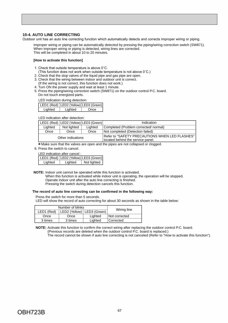
67
10-4. AUTO LINE CORRECTING Outdoor unit has an auto line correcting function which automatically detects and corrects improper wiring or piping.
Improper wiring or piping can be automatically detected by pressing the piping/wiring correction switch (SW871). When improper wiring or piping is detected, wiring lines are corrected. This will be completed in about 10 to 20 minutes.
[How to activate this function]
2. Check that the stop valves of the liquid pipe and gas pipe are open. 3. Check that the wiring between indoor and outdoor unit is correct. (If the wiring is not correct, this function does not work.) 4. Turn ON the power supply and wait at least 1 minute. 5. Press the piping/wiring correction switch (SW871) on the outdoor control P.C. board. Do not touch energized parts.
6. Press the switch to cancel.
NOTE: Indoor unit cannot be operated while this function is activated. When this function is activated while indoor unit is operating, the operation will be stopped. Operate indoor unit after the auto line correcting is finished. Pressing the switch during detection cancels this function.
Make sure that the valves are open and the pipes are not collapsed or clogged.
LED indication after cancel :
LED1 (Red)Lighted
LED indication during detection:
LED indication after detection:
LED2 (Yellow)Lighted
LED3 (Green)Once
LED1 (Red)Lighted
LED2 (Yellow)Lighted
LED3 (Green)Not lighted
LED1 (Red)LightedOnce
LED2 (Yellow)Not lighted
Once
Other indications
LED3 (Green)LightedOnce
Completed (Problem corrected/ normal)Not completed (Detection failed)Refer to "SAFETY PRECAUTIONS WHEN LED FLASHES"located behind the service panel.
Indication
Press the switch for more than 5 seconds.LED will show the record of auto correcting for about 30 seconds as shown in the table below:
NOTE: Activate this function to confirm the correct wiring after replacing the outdoor control P.C. board. (Previous records are deleted when the outdoor control P.C. board is replaced.) The record cannot be shown if auto line correcting is not canceled (Refer to "How to activate this function").
LED1 (Red)Once
3 times
LED2 (Yellow)Once
3 times
LED3 (Green)LightedLighted
Not correctedCorrected
Number of blinks Wiring line
The record of auto line correcting can be confirmed in the following way:
OBH723B
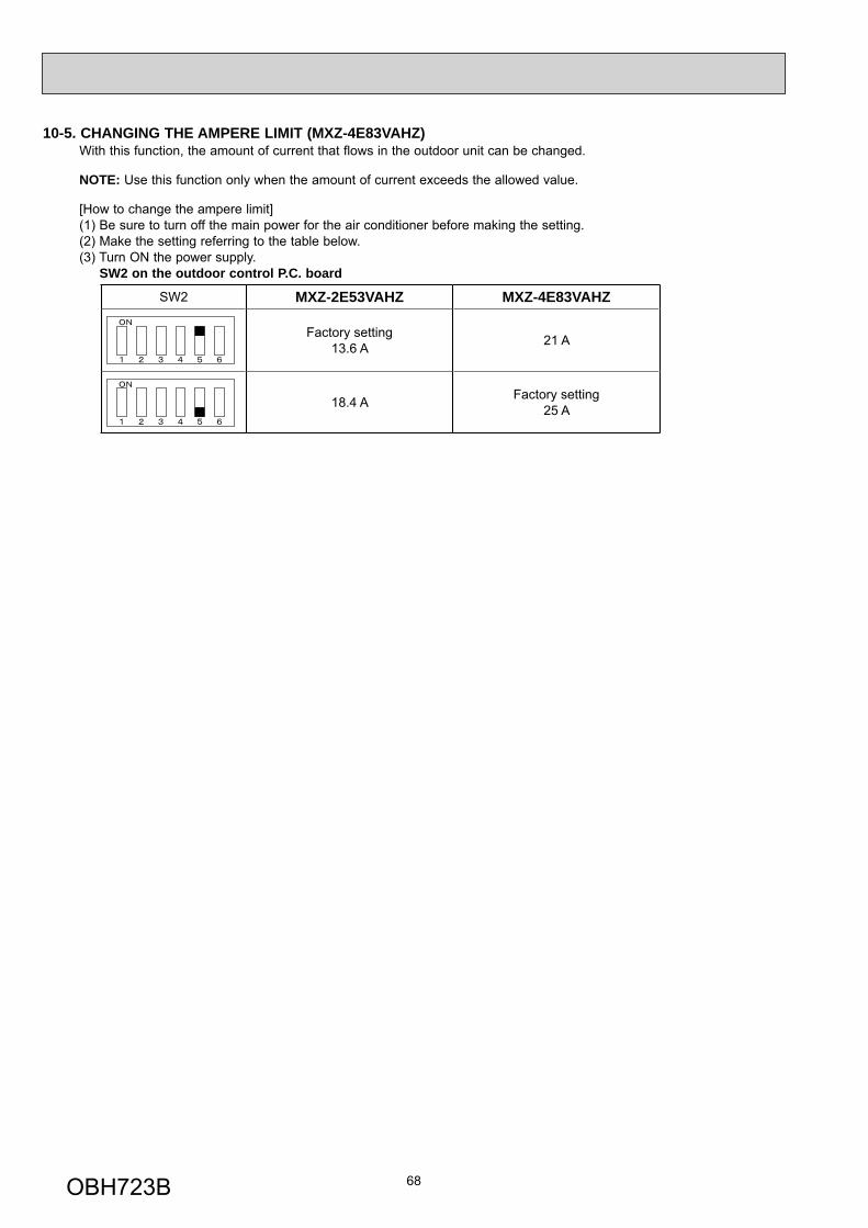
68
10-5. CHANGING THE AMPERE LIMIT (MXZ-4E83VAHZ)With this function, the amount of current that flows in the outdoor unit can be changed.
NOTE: Use this function only when the amount of current exceeds the allowed value.
[How to change the ampere limit](1) Be sure to turn off the main power for the air conditioner before making the setting.(2) Make the setting referring to the table below.(3) Turn ON the power supply. SW2 on the outdoor control P.C. board
SW2 MXZ-2E53VAHZ MXZ-4E83VAHZ
Factory setting13.6 A 21 A
18.4 A Factory setting25 A
OBH723B
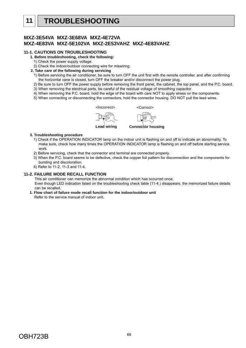
69
11 TROUBLESHOOTING
3. Troubleshooting procedure1) Check if the OPERATION INDICATOR lamp on the indoor unit is fl ashing on and off to indicate an abnormality. To
make sure, check how many times the OPERATION INDICATOR lamp is fl ashing on and off before starting service work.
2) Before servicing, check that the connector and terminal are connected properly.3) When the P.C. board seems to be defective, check the copper foil pattern for disconnection and the components for
bursting and discoloration.4) Refer to 11-2, 11-3 and 11-4.
11-1. CAUTIONS ON TROUBLESHOOTING1. Before troubleshooting, check the following:
1) Check the power supply voltage.2) Check the indoor/outdoor connecting wire for miswiring.
2. Take care of the following during servicing1) Before servicing the air conditioner, be sure to turn OFF the unit fi rst with the remote controller, and after confi rming
the horizontal vane is closed, turn OFF the breaker and/or disconnect the power plug.2) Be sure to turn OFF the power supply before removing the front panel, the cabinet, the top panel, and the P.C. board.3) When removing the electrical parts, be careful of the residual voltage of smoothing capacitor.4) When removing the P.C. board, hold the edge of the board with care NOT to apply stress on the components.5) When connecting or disconnecting the connectors, hold the connector housing. DO NOT pull the lead wires.
11-2. FAILURE MODE RECALL FUNCTIONThis air conditioner can memorize the abnormal condition which has occurred once.Even though LED indication listed on the troubleshooting check table (11-4.) disappears, the memorized failure details can be recalled.
1. Flow chart of failure mode recall function for the indoor/outdoor unit Refer to the service manual of indoor unit.
Lead wiring Connector housing
<Incorrect> <Correct>
MXZ-3E54VA MXZ-3E68VA MXZ-4E72VAMXZ-4E83VA MXZ-5E102VA MXZ-2E53VAHZ MXZ-4E83VAHZ
OBH723B
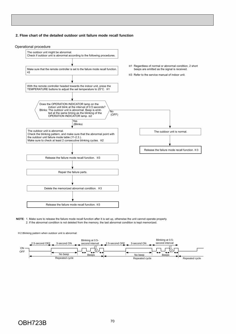
70
2. Flow chart of the detailed outdoor unit failure mode recall function
2.Blinking pattern when outdoor unit is abnormal:
ONOFF
No beep BeepsRepeated cycle
2.5-second OFF 3-second ONBlinking at 0.5-second interval
No beep BeepsRepeated cycle
2.5-second OFF 3-second ONBlinking at 0.5-second interval
Repeated cycle
Does the OPERATION INDICATOR lamp on the indoor unit blink at the interval of 0.5 seconds?
Blinks: The outdoor unit is abnormal. Beep is emit-ted at the same timing as the blinking of the OPERATION INDICATOR lamp. 2
Yes (Blinks)
No (OFF)
The outdoor unit might be abnormal.Check if outdoor unit is abnormal according to the following procedures.
Operational procedure
With the remote controller headed towards the indoor unit, press the TEMPERATURE buttons to adjust the set temperature to 25°C. 1
1 Regardless of normal or abnormal condition, 2 short beeps are emitted as the signal is received.
The outdoor unit is abnormal.Check the blinking pattern, and make sure that the abnormal point with the outdoor unit failure mode table (11-2.3.).Make sure to check at least 2 consecutive blinking cycles. 2
Repair the failure parts.
The outdoor unit is normal.
Release the failure mode recall function. 3
NOTE: 1. Make sure to release the failure mode recall function after it is set up, otherwise the unit cannot operate properly. 2. If the abnormal condition is not deleted from the memory, the last abnormal condition is kept memorized.
Delete the memorized abnormal condition. 3
Release the failure mode recall function. 3
3 Refer to the service manual of indoor unit.
Release the failure mode recall function. 3
Make sure that the remote controller is set to the failure mode recall function.3
OBH723B
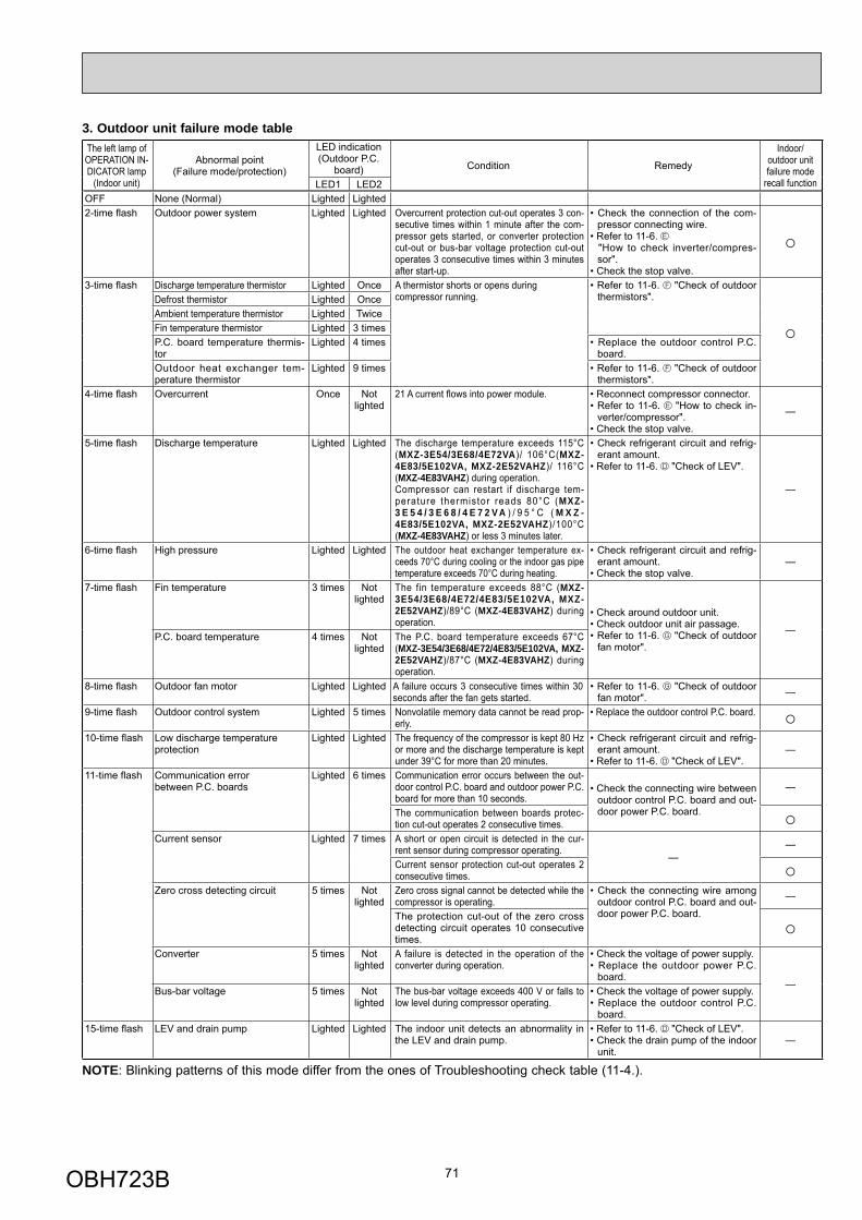
71
3. Outdoor unit failure mode tableThe left lamp of OPERATION IN-DICATOR lamp
(Indoor unit)
Abnormal point(Failure mode/protection)
LED indication(Outdoor P.C.
board) Condition Remedy
Indoor/outdoor unit failure mode
recall functionLED1 LED2OFF None (Normal) Lighted Lighted2-time fl ash Outdoor power system Lighted Lighted Overcurrent protection cut-out operates 3 con-
secutive times within 1 minute after the com-pressor gets started, or converter protection cut-out or bus-bar voltage protection cut-out operates 3 consecutive times within 3 minutes after start-up.
• Check the connection of the com-pressor connecting wire.
• Refer to 11-6. "How to check inverter/compres-
sor".• Check the stop valve.
○
3-time fl ash Discharge temperature thermistor Lighted Once A thermistor shorts or opens duringcompressor running.
• Refer to 11-6. "Check of outdoor thermistors".
○
Defrost thermistor Lighted OnceAmbient temperature thermistor Lighted TwiceFin temperature thermistor Lighted 3 timesP.C. board temperature thermis-tor
Lighted 4 times • Replace the outdoor control P.C. board.
Outdoor heat exchanger tem-perature thermistor
Lighted 9 times • Refer to 11-6. "Check of outdoor thermistors".
4-time fl ash Overcurrent Once Not lighted
21 A current fl ows into power module. • Reconnect compressor connector.• Refer to 11-6. "How to check in-
verter/compressor". • Check the stop valve.
—
5-time fl ash Discharge temperature Lighted Lighted The discharge temperature exceeds 115°C (MXZ-3E54/3E68/4E72VA)/ 106°C(MXZ-4E83/5E102VA, MXZ-2E52VAHZ)/ 116°C (MXZ-4E83VAHZ) during operation. Compressor can restart if discharge tem-perature thermistor reads 80°C (MXZ-3 E 5 4 / 3 E 6 8 / 4 E 7 2 V A ) / 9 5 ° C ( M X Z -4E83/5E102VA, MXZ-2E52VAHZ)/100°C (MXZ-4E83VAHZ) or less 3 minutes later.
• Check refrigerant circuit and refrig-erant amount.
• Refer to 11-6. "Check of LEV".
—
6-time fl ash High pressure Lighted Lighted The outdoor heat exchanger temperature ex-ceeds 70°C during cooling or the indoor gas pipe temperature exceeds 70°C during heating.
• Check refrigerant circuit and refrig-erant amount.
• Check the stop valve.—
7-time fl ash Fin temperature 3 times Not lighted
The fin temperature exceeds 88°C (MXZ-3E54/3E68/4E72/4E83/5E102VA, MXZ-2E52VAHZ)/89°C (MXZ-4E83VAHZ) during operation.
• Check around outdoor unit.• Check outdoor unit air passage.• Refer to 11-6. "Check of outdoor
fan motor".
—P.C. board temperature 4 times Not
lightedThe P.C. board temperature exceeds 67°C (MXZ-3E54/3E68/4E72/4E83/5E102VA, MXZ-2E52VAHZ)/87°C (MXZ-4E83VAHZ) during operation.
8-time fl ash Outdoor fan motor Lighted Lighted A failure occurs 3 consecutive times within 30 seconds after the fan gets started.
• Refer to 11-6. "Check of outdoor fan motor". —
9-time fl ash Outdoor control system Lighted 5 times Nonvolatile memory data cannot be read prop-erly.
• Replace the outdoor control P.C. board. ○10-time fl ash Low discharge temperature
protectionLighted Lighted The frequency of the compressor is kept 80 Hz
or more and the discharge temperature is kept under 39°C for more than 20 minutes.
• Check refrigerant circuit and refrig-erant amount.
• Refer to 11-6. "Check of LEV".—
11-time fl ash Communication errorbetween P.C. boards
Lighted 6 times Communication error occurs between the out-door control P.C. board and outdoor power P.C. board for more than 10 seconds.
• Check the connecting wire between outdoor control P.C. board and out-door power P.C. board.
—
The communication between boards protec-tion cut-out operates 2 consecutive times. ○
Current sensor Lighted 7 times A short or open circuit is detected in the cur-rent sensor during compressor operating.
——
Current sensor protection cut-out operates 2 consecutive times. ○
Zero cross detecting circuit 5 times Not lighted
Zero cross signal cannot be detected while the compressor is operating.
• Check the connecting wire among outdoor control P.C. board and out-door power P.C. board.
—
The protection cut-out of the zero cross detecting circuit operates 10 consecutive times.
○Converter 5 times Not
lightedA failure is detected in the operation of the converter during operation.
• Check the voltage of power supply.• Replace the outdoor power P.C.
board.—
Bus-bar voltage 5 times Not lighted
The bus-bar voltage exceeds 400 V or falls to low level during compressor operating.
• Check the voltage of power supply.• Replace the outdoor control P.C.
board.15-time fl ash LEV and drain pump Lighted Lighted The indoor unit detects an abnormality in
the LEV and drain pump.• Refer to 11-6. "Check of LEV".• Check the drain pump of the indoor
unit.—
NOTE: Blinking patterns of this mode differ from the ones of Troubleshooting check table (11-4.).
OBH723B
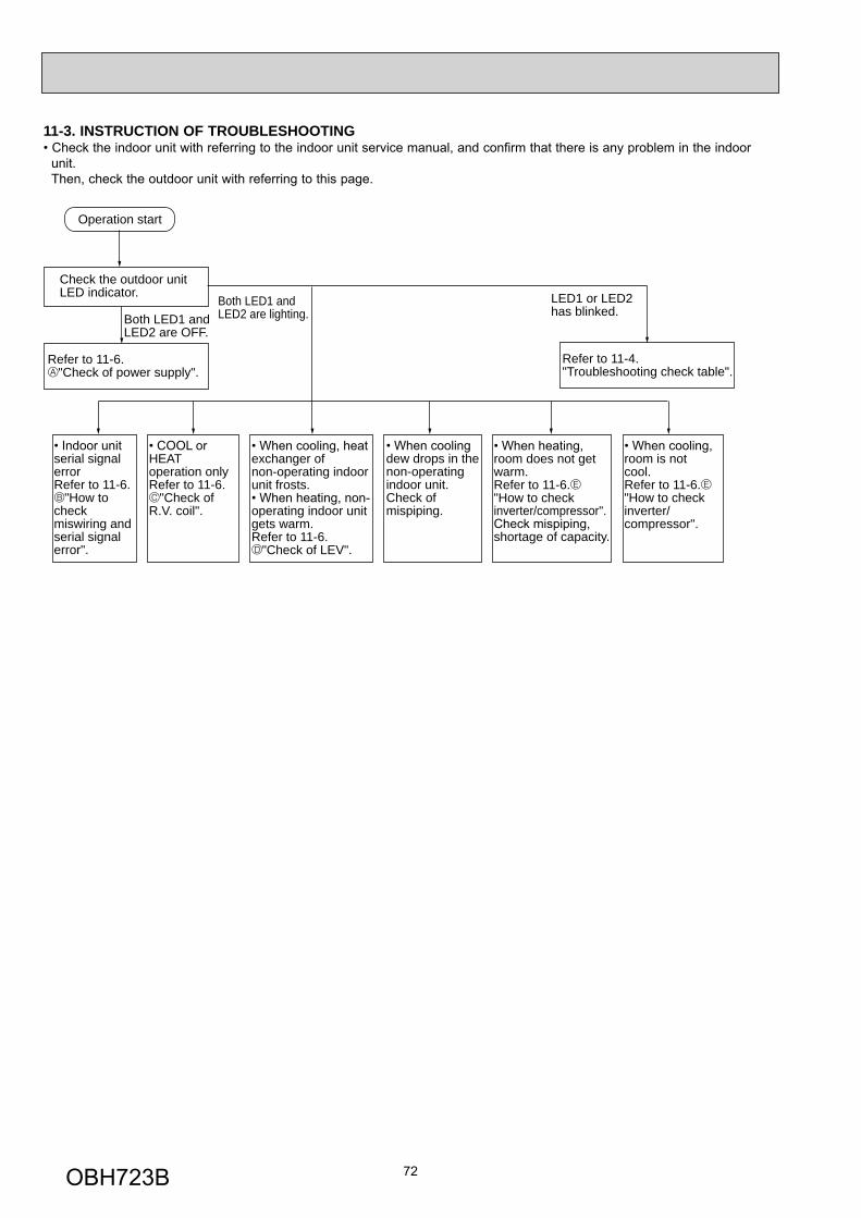
72
Operation start
Check the outdoor unit LED indicator.
Refer to 11-6. "Check of power supply".
serial signal errorRefer to 11-6. "How to check miswiring andserial signalerror".
HEAToperation onlyRefer to 11-6. "Check of R.V. coil".
room is not cool.Refer to 11-6."How to checkinverter/compressor".
exchanger of non-operating indoor unit frosts.
operating indoor unit gets warm.Refer to 11-6. "Check of LEV".
room does not get warm.Refer to 11-6."How to checkinverter/compressor".
shortage of capacity.
dew drops in thenon-operatingindoor unit.Check ofmispiping.
Refer to 11-4. "Troubleshooting check table".
Both LED1 andLED2 are OFF.
Both LED1 and LED2 are lighting.
LED1 or LED2has blinked.
11-3. INSTRUCTION OF TROUBLESHOOTING• Check the indoor unit with referring to the indoor unit service manual, and confirm that there is any problem in the indoor unit. Then, check the outdoor unit with referring to this page.
OBH723B
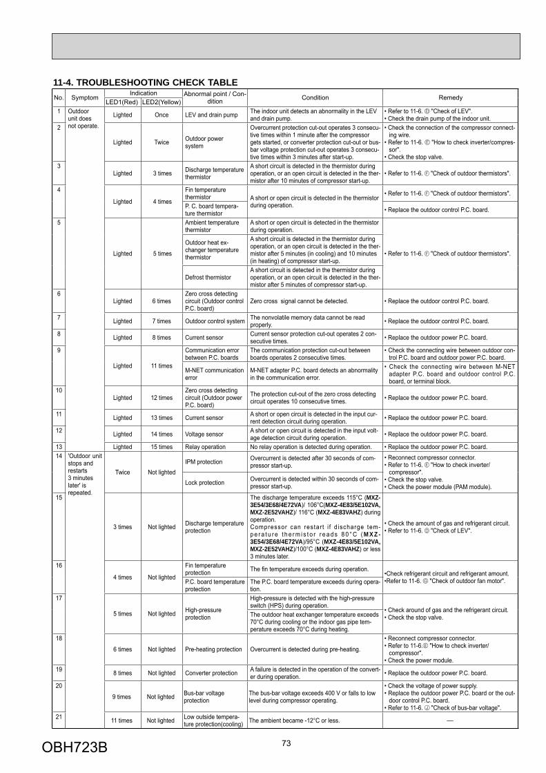
73
11-4. TROUBLESHOOTING CHECK TABLENo. Symptom
Indication Abnormal point / Con-dition Condition Remedy
LED1(Red) LED2(Yellow)1 Outdoor
unit doesnot operate.
Lighted Once LEV and drain pump The indoor unit detects an abnormality in the LEV and drain pump.
• Refer to 11-6. "Check of LEV".• Check the drain pump of the indoor unit.
2
Lighted Twice Outdoor power system
Overcurrent protection cut-out operates 3 consecu-tive times within 1 minute after the compressor gets started, or converter protection cut-out or bus-bar voltage protection cut-out operates 3 consecu-tive times within 3 minutes after start-up.
• Check the connection of the compressor connect-ing wire.
• Refer to 11-6. "How to check inverter/compres-sor".
• Check the stop valve.3
Lighted 3 times Discharge temperaturethermistor
A short circuit is detected in the thermistor during operation, or an open circuit is detected in the ther-mistor after 10 minutes of compressor start-up.
• Refer to 11-6. "Check of outdoor thermistors".
4
Lighted 4 times
Fin temperaturethermistor A short or open circuit is detected in the thermistor
during operation.
• Refer to 11-6. "Check of outdoor thermistors".
P. C. board tempera-ture thermistor • Replace the outdoor control P.C. board.
5
Lighted 5 times
Ambient temperaturethermistor
A short or open circuit is detected in the thermistor during operation.
• Refer to 11-6. "Check of outdoor thermistors".
Outdoor heat ex-changer temperature thermistor
A short circuit is detected in the thermistor during operation, or an open circuit is detected in the ther-mistor after 5 minutes (in cooling) and 10 minutes (in heating) of compressor start-up.
Defrost thermistorA short circuit is detected in the thermistor during operation, or an open circuit is detected in the ther-mistor after 5 minutes of compressor start-up.
6Lighted 6 times
Zero cross detecting circuit (Outdoor control P.C. board)
Zero cross signal cannot be detected. • Replace the outdoor control P.C. board.
7 Lighted 7 times Outdoor control system The nonvolatile memory data cannot be read properly. • Replace the outdoor control P.C. board.
8 Lighted 8 times Current sensor Current sensor protection cut-out operates 2 con-secutive times. • Replace the outdoor power P.C. board.
9
Lighted 11 times
Communication errorbetween P.C. boards
The communication protection cut-out between boards operates 2 consecutive times.
• Check the connecting wire between outdoor con-trol P.C. board and outdoor power P.C. board.
M-NET communication error
M-NET adapter P.C. board detects an abnormality in the communication error.
• Check the connecting wire between M-NET adapter P.C. board and outdoor control P.C. board, or terminal block.
10Lighted 12 times
Zero cross detecting circuit (Outdoor power P.C. board)
The protection cut-out of the zero cross detecting circuit operates 10 consecutive times. • Replace the outdoor power P.C. board.
11 Lighted 13 times Current sensor A short or open circuit is detected in the input cur-rent detection circuit during operation. • Replace the outdoor power P.C. board.
12 Lighted 14 times Voltage sensor A short or open circuit is detected in the input volt-age detection circuit during operation. • Replace the outdoor power P.C. board.
13 Lighted 15 times Relay operation No relay operation is detected during operation. • Replace the outdoor power P.C. board.14 'Outdoor unit
stops and restarts 3 minutes later' is repeated.
Twice Not lightedIPM protection Overcurrent is detected after 30 seconds of com-
pressor start-up.• Reconnect compressor connector.• Refer to 11-6. "How to check inverter/ compressor". • Check the stop valve.• Check the power module (PAM module).
Lock protection Overcurrent is detected within 30 seconds of com-pressor start-up.
15
3 times Not lighted Discharge temperatureprotection
The discharge temperature exceeds 115°C (MXZ-3E54/3E68/4E72VA)/ 106°C(MXZ-4E83/5E102VA, MXZ-2E52VAHZ)/ 116°C (MXZ-4E83VAHZ) during operation. Compressor can restart i f d ischarge tem-p e r a t u r e t h e r m i s t o r r e a d s 8 0 ° C ( M X Z -3E54/3E68/4E72VA)/95°C (MXZ-4E83/5E102VA, MXZ-2E52VAHZ)/100°C (MXZ-4E83VAHZ) or less 3 minutes later.
• Check the amount of gas and refrigerant circuit.• Refer to 11-6. "Check of LEV".
16
4 times Not lighted
Fin temperatureprotection The fi n temperature exceeds during operation.
•Check refrigerant circuit and refrigerant amount.•Refer to 11-6. "Check of outdoor fan motor".P.C. board temperature
protectionThe P.C. board temperature exceeds during opera-tion.
17
5 times Not lighted High-pressure protection
High-pressure is detected with the high-pressure switch (HPS) during operation.
• Check around of gas and the refrigerant circuit.• Check the stop valve.The outdoor heat exchanger temperature exceeds
70°C during cooling or the indoor gas pipe tem-perature exceeds 70°C during heating.
18
6 times Not lighted Pre-heating protection Overcurrent is detected during pre-heating.
• Reconnect compressor connector.• Refer to 11-6. "How to check inverter/ compressor".• Check the power module.
19 8 times Not lighted Converter protection A failure is detected in the operation of the convert-er during operation. • Replace the outdoor power P.C. board.
20
9 times Not lighted Bus-bar voltageprotection
The bus-bar voltage exceeds 400 V or falls to low level during compressor operating.
• Check the voltage of power supply.• Replace the outdoor power P.C. board or the out-
door control P.C. board.• Refer to 11-6. "Check of bus-bar voltage".
21 11 times Not lighted Low outside tempera-ture protection(cooling) The ambient became -12°C or less. —
OBH723B
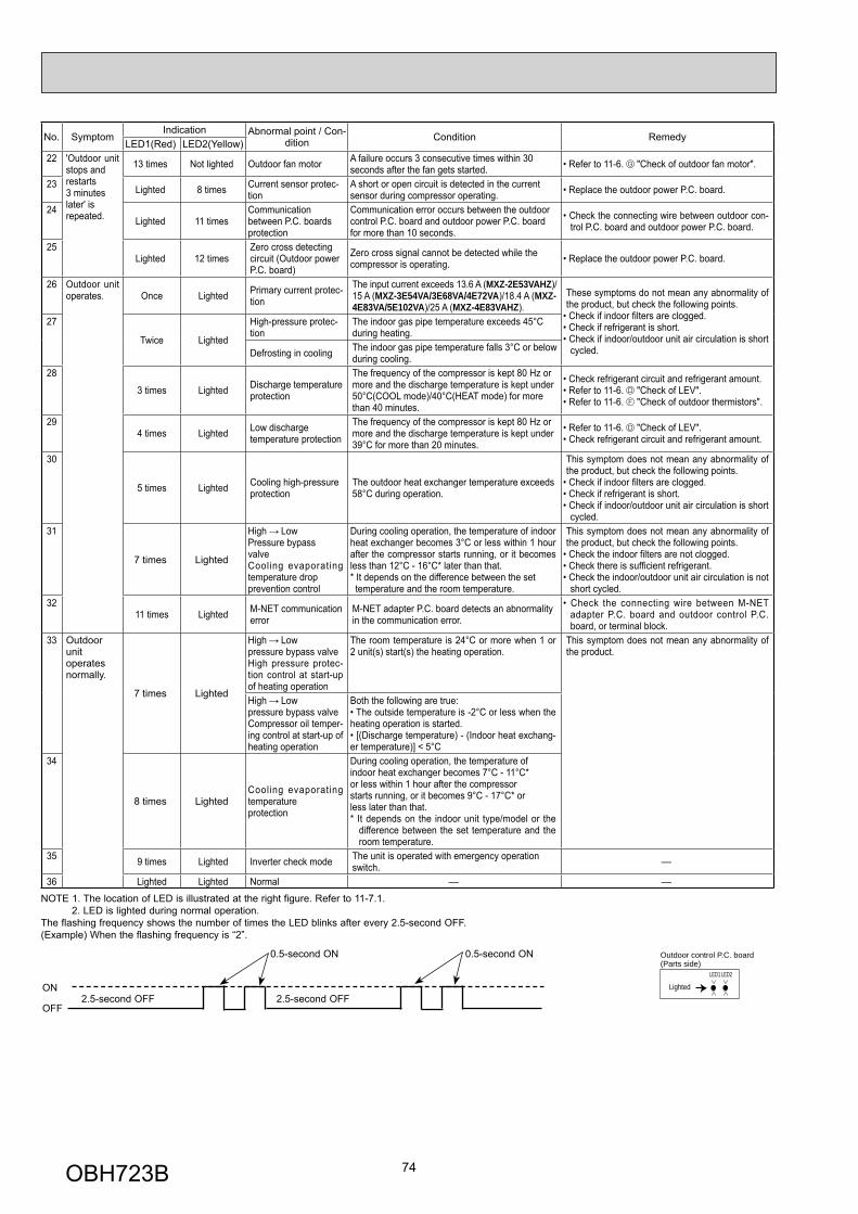
74
No. SymptomIndication Abnormal point / Con-
dition Condition RemedyLED1(Red) LED2(Yellow)
22 'Outdoor unit stops and restarts 3 minutes later' is repeated.
13 times Not lighted Outdoor fan motor A failure occurs 3 consecutive times within 30 seconds after the fan gets started. • Refer to 11-6. "Check of outdoor fan motor".
23 Lighted 8 times Current sensor protec-tion
A short or open circuit is detected in the current sensor during compressor operating. • Replace the outdoor power P.C. board.
24Lighted 11 times
Communication between P.C. boards protection
Communication error occurs between the outdoor control P.C. board and outdoor power P.C. board for more than 10 seconds.
• Check the connecting wire between outdoor con-trol P.C. board and outdoor power P.C. board.
25Lighted 12 times
Zero cross detecting circuit (Outdoor power P.C. board)
Zero cross signal cannot be detected while the compressor is operating. • Replace the outdoor power P.C. board.
26 Outdoor unit operates. Once Lighted Primary current protec-
tion
The input current exceeds 13.6 A (MXZ-2E53VAHZ)/15 A (MXZ-3E54VA/3E68VA/4E72VA)/18.4 A (MXZ-4E83VA/5E102VA)/25 A (MXZ-4E83VAHZ).
These symptoms do not mean any abnormality of the product, but check the following points.
• Check if indoor fi lters are clogged.• Check if refrigerant is short.• Check if indoor/outdoor unit air circulation is short
cycled.
27
Twice Lighted
High-pressure protec-tion
The indoor gas pipe temperature exceeds 45°C during heating.
Defrosting in cooling The indoor gas pipe temperature falls 3°C or below during cooling.
28
3 times Lighted Discharge temperature protection
The frequency of the compressor is kept 80 Hz or more and the discharge temperature is kept under 50°C(COOL mode)/40°C(HEAT mode) for more than 40 minutes.
• Check refrigerant circuit and refrigerant amount.• Refer to 11-6. "Check of LEV".• Refer to 11-6. "Check of outdoor thermistors".
294 times Lighted Low discharge
temperature protection
The frequency of the compressor is kept 80 Hz or more and the discharge temperature is kept under 39°C for more than 20 minutes.
• Refer to 11-6. "Check of LEV".• Check refrigerant circuit and refrigerant amount.
30
5 times Lighted Cooling high-pressureprotection
The outdoor heat exchanger temperature exceeds 58°C during operation.
This symptom does not mean any abnormality of the product, but check the following points.
• Check if indoor fi lters are clogged. • Check if refrigerant is short.• Check if indoor/outdoor unit air circulation is short
cycled.31
7 times Lighted
High LowPressure bypass valveCooling evaporating temperature drop prevention control
During cooling operation, the temperature of indoor heat exchanger becomes 3°C or less within 1 hour after the compressor starts running, or it becomes less than 12°C - 16°C* later than that.* It depends on the difference between the set temperature and the room temperature.
This symptom does not mean any abnormality of the product, but check the following points.
• Check the indoor fi lters are not clogged.• Check there is suffi cient refrigerant.• Check the indoor/outdoor unit air circulation is not
short cycled.32
11 times Lighted M-NET communication error
M-NET adapter P.C. board detects an abnormality in the communication error.
• Check the connecting wire between M-NET adapter P.C. board and outdoor control P.C. board, or terminal block.
33 Outdoor unitoperatesnormally.
7 times Lighted
High Low pressure bypass valveHigh pressure protec-tion control at start-up of heating operation
The room temperature is 24°C or more when 1 or 2 unit(s) start(s) the heating operation.
This symptom does not mean any abnormality of the product.
High Low pressure bypass valveCompressor oil temper-ing control at start-up of heating operation
Both the following are true:• The outside temperature is -2°C or less when the heating operation is started.• [(Discharge temperature) - (Indoor heat exchang-er temperature)] < 5°C
34
8 times LightedCooling evaporating temperatureprotection
During cooling operation, the temperature of indoor heat exchanger becomes 7°C - 11°C*or less within 1 hour after the compressor starts running, or it becomes 9°C - 17°C* or less later than that.* It depends on the indoor unit type/model or the
difference between the set temperature and the room temperature.
35 9 times Lighted Inverter check mode The unit is operated with emergency operation switch. —
36 Lighted Lighted Normal — —
NOTE 1. The location of LED is illustrated at the right figure. Refer to 11-7.1. 2. LED is lighted during normal operation. The flashing frequency shows the number of times the LED blinks after every 2.5-second OFF.(Example) When the flashing frequency is “2”.
ON
OFF2.5-second OFF 2.5-second OFF
0.5-second ON 0.5-second ON
LED1 LED2
Lighted
Outdoor control P.C. board (Parts side)
OBH723B
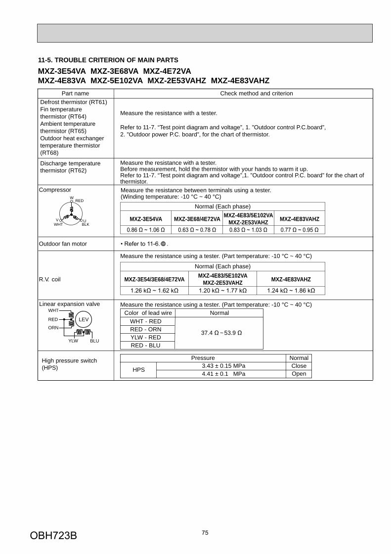
75
11-5. TROUBLE CRITERION OF MAIN PARTS
W
UVWHT
RED
BLK
LEV
WHT
RED
YLW
ORN
BLU
Linear expansion valve
37.4 ~ 53.9
NormalColor of lead wireWHT - REDRED - ORNYLW - REDRED - BLU
High pressure switch(HPS)
Pressure Normal
HPS3.43 ± 0.15 MPa4.41 ± 0.1 MPa Open
Close
Discharge temperaturethermistor (RT62)
Part name Check method and criterion
Measure the resistance between terminals using a tester.(Winding temperature: -10 °C ~ 40 °C)
Compressor
Outdoor fan motor
R.V. coil
Defrost thermistor (RT61)Fin temperature thermistor (RT64)Ambient temperature thermistor (RT65) Outdoor heat exchangertemperature thermistor(RT68)
Measure the resistance with a tester.
Refer to 11-7. “Test point diagram and voltage”, 1. ”Outdoor control P.C.board”, 2. ”Outdoor power P.C. board”, for the chart of thermistor.
Measure the resistance with a tester.Before measurement, hold the thermistor with your hands to warm it up.Refer to 11-7. “Test point diagram and voltage”,1. ”Outdoor control P.C. board” for the chart of thermistor.
MXZ-3E54VA MXZ-3E68/4E72VA MXZ-4E83/5E102VAMXZ-2E53VAHZ MXZ-4E83VAHZ
Normal (Each phase)
MXZ-4E83/5E102VAMXZ-2E53VAHZMXZ-3E54/3E68/4E72VA MXZ-4E83VAHZ
Normal (Each phase)
Measure the resistance using a tester. (Part temperature: -10 °C ~ 40 °C)
Measure the resistance using a tester. (Part temperature: -10 °C ~ 40 °C)
MXZ-3E54VA MXZ-3E68VA MXZ-4E72VAMXZ-4E83VA MXZ-5E102VA MXZ-2E53VAHZ MXZ-4E83VAHZ
OBH723B
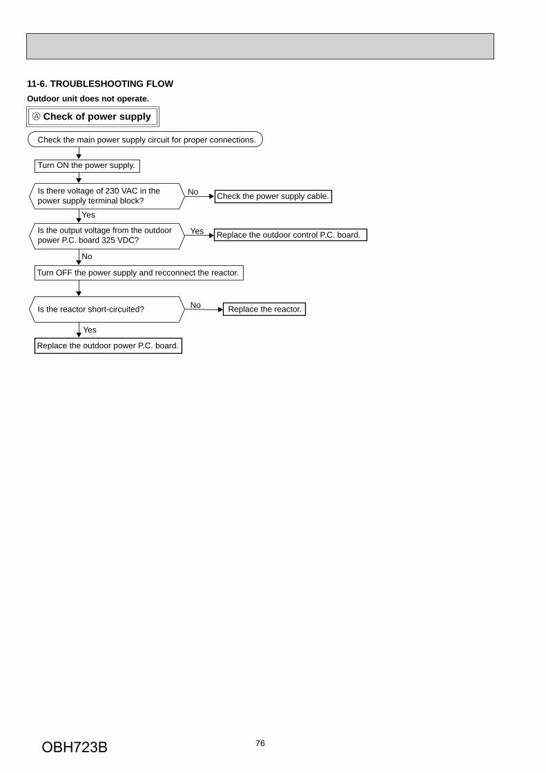
76
Check of power supply
Outdoor unit does not operate.
11-6. TROUBLESHOOTING FLOW
Turn ON the power supply.
No
Yes
Yes
No
No
Yes
Check the main power supply circuit for proper connections.
Is there voltage of 230 VAC in the power supply terminal block?
Is the output voltage from the outdoor power P.C. board 325 VDC?
Check the power supply cable.
Replace the outdoor power P.C. board.
Turn OFF the power supply and recconnect the reactor.
Is the reactor short-circuited? Replace the reactor.
Replace the outdoor control P.C. board.
OBH723B
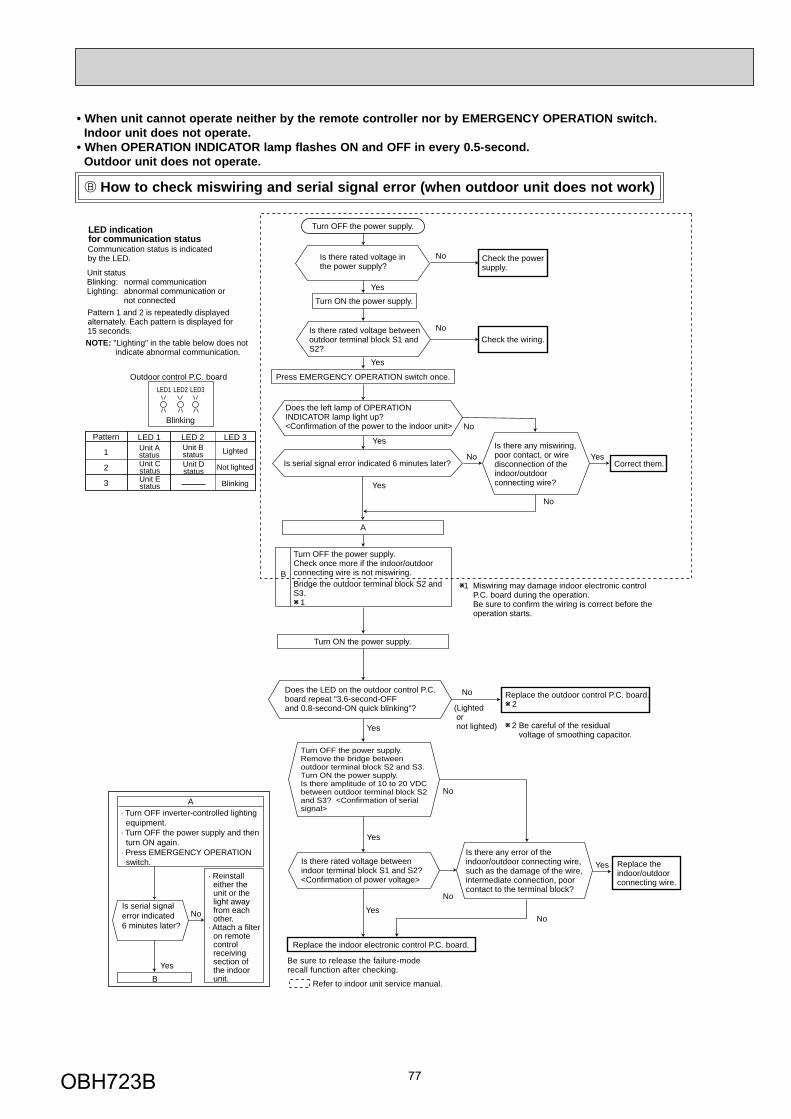
77
Is there rated voltage in the power supply?
Is there any miswiring, poor contact, or wire disconnection of the indoor/outdoor connecting wire?
1 Miswiring may damage indoor electronic control P.C. board during the operation. Be sure to confirm the wiring is correct before the operation starts.
(Lighted or not lighted)
No
Yes
No
Yes
Yes
No
Yes
No
Be sure to release the failure-moderecall function after checking.
No
No
Yes
No
Yes
Yes
Yes
No
Yes
Refer to indoor unit service manual.
Turn OFF the power supply.
Turn ON the power supply.
Is there rated voltage betweenoutdoor terminal block S1 andS2?
Does the left lamp of OPERATIONINDICATOR lamp light up? <Confirmation of the power to the indoor unit>
Press EMERGENCY OPERATION switch once.
Check the powersupply.
A
Turn OFF the power supply.Check once more if the indoor/outdoorconnecting wire is not miswiring.Bridge the outdoor terminal block S2 andS3. 1
B
Turn ON the power supply.
Check the wiring.
Correct them.
Turn OFF the power supply.Remove the bridge betweenoutdoor terminal block S2 and S3.Turn ON the power supply.Is there amplitude of 10 to 20 VDCbetween outdoor terminal block S2and S3? <Confirmation of serialsignal>
Is there rated voltage between indoor terminal block S1 and S2?<Confirmation of power voltage>
Replace the indoor electronic control P.C. board.
2 Be careful of the residual voltage of smoothing capacitor.
Replace the outdoor control P.C. board. 2
Is there any error of theindoor/outdoor connecting wire,such as the damage of the wire,intermediate connection, poorcontact to the terminal block?
Replace theindoor/outdoorconnecting wire.
Is serial signalerror indicated 6 minutes later?
Yes
No
· Turn OFF inverter-controlled lighting equipment.
· Turn OFF the power supply and then turn ON again.
· Press EMERGENCY OPERATION switch.
B
· Reinstall either the unit or the light away from each other.
· Attach a filter on remote control receiving section of the indoor unit.
A
Is serial signal error indicated 6 minutes later?
No
Does the LED on the outdoor control P.C. board repeat "3.6-second-OFF and 0.8-second-ON quick blinking"?
LED indication for communication statusCommunication status is indicated by the LED.
Blinking: normal communicationLighting: abnormal communication or not connectedPattern 1 and 2 is repeatedly displayed alternately. Each pattern is displayed for 15 seconds.NOTE: "Lighting" in the table below does not indicate abnormal communication.
Unit status
Outdoor control P.C. board
Blinking
LED1 LED2 LED3
LED 1 LED 3LED 2Pattern
1
2
3
Unit Bstatus
Unit Cstatus
Unit Astatus
Unit Dstatus
Unit Estatus
Not lighted
Lighted
Blinking
How to check miswiring and serial signal error (when outdoor unit does not work)
• When unit cannot operate neither by the remote controller nor by EMERGENCY OPERATION switch. Indoor unit does not operate.• When OPERATION INDICATOR lamp flashes ON and OFF in every 0.5-second. Outdoor unit does not operate.
OBH723B
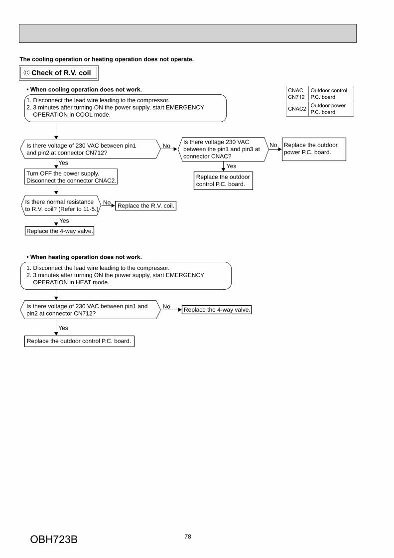
78
Check of R.V. coil
The cooling operation or heating operation does not operate.
No
Yes
No
Yes
No
Yes
No
Yes
1. Disconnect the lead wire leading to the compressor.2. 3 minutes after turning ON the power supply, start EMERGENCY OPERATION in COOL mode.
Is there voltage of 230 VAC between pin1 and pin2 at connector CN712?
Turn OFF the power supply.Disconnect the connector CNAC2.
Replace the 4-way valve.
Replace the outdoorcontrol P.C. board.
Replace the R.V. coil.
Is there voltage 230 VAC between the pin1 and pin3 atconnector CNAC?
Replace the outdoor power P.C. board.
Is there normal resistance to R.V. coil? (Refer to 11-5.)
1. Disconnect the lead wire leading to the compressor.2. 3 minutes after turning ON the power supply, start EMERGENCY OPERATION in HEAT mode.
Is there voltage of 230 VAC between pin1 and pin2 at connector CN712? Replace the 4-way valve.
Replace the outdoor control P.C. board.
CNACCN712
Outdoor control P.C. board
CNAC2 Outdoor power P.C. board
OBH723B
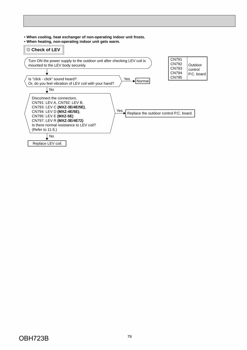
79
Check of LEV
No
Yes
No
Yes
Turn ON the power supply to the outdoor unit after checking LEV coil is mounted to the LEV body securely.
Is "click - click" sound heard?Or, do you feel vibration of LEV coil with your hand?
Disconnect the connectors. CN791: LEV A, CN792: LEV B, CN793: LEV C (MXZ-3E/4E/5E), CN794: LEV D (MXZ-4E/5E), CN795: LEV E (MXZ-5E)CN797: LEV R (MXZ-3E/4E72) Is there normal resistance to LEV coil?(Refer to 11-5.)
Normal
Replace the outdoor control P.C. board.
Replace LEV coil.
• When cooling, heat exchanger of non-operating indoor unit frosts.• When heating, non-operating indoor unit gets warm.
CN791CN792CN793CN794CN795
OutdoorcontrolP.C. board
OBH723B
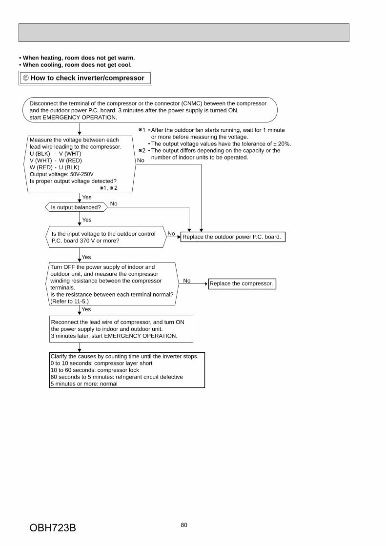
80
How to check inverter/compressor
• When heating, room does not get warm.• When cooling, room does not get cool.
Disconnect the terminal of the compressor or the connector (CNMC) between the compressor and the outdoor power P.C. board. 3 minutes after the power supply is turned ON, start EMERGENCY OPERATION.
Is output balanced?
Clarify the causes by counting time until the inverter stops.0 to 10 seconds: compressor layer short 10 to 60 seconds: compressor lock60 seconds to 5 minutes: refrigerant circuit defective5 minutes or more: normal
Turn OFF the power supply of indoor and outdoor unit, and measure the compressor winding resistance between the compressor terminals.Is the resistance between each terminal normal?(Refer to 11-5.)
Is the input voltage to the outdoor control P.C. board 370 V or more?
Reconnect the lead wire of compressor, and turn ON the power supply to indoor and outdoor unit. 3 minutes later, start EMERGENCY OPERATION.
Replace the compressor.
Replace the outdoor power P.C. board.
or more before measuring the voltage.
number of indoor units to be operated.
Measure the voltage between each lead wire leading to the compressor.U (BLK) - V (WHT) V (WHT) - W (RED) W (RED) - U (BLK) Output voltage: Is proper output voltage detected?
No
No
Yes
Yes
Yes
No
Yes
No
OBH723B
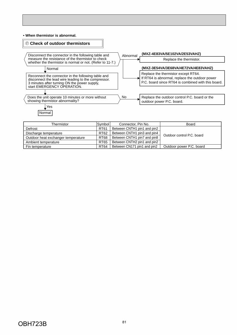
81
Check of outdoor thermistors
• When thermistor is abnormal.
ThermistorDefrostDischarge temperatureOutdoor heat exchanger temperature Ambient temperatureFin temperature
SymbolRT61RT62RT68RT65RT64
Connector, Pin No.Between CNTH1 pin1 and pin2Between CNTH1 pin3 and pin4Between CNTH1 pin7 and pin8Between CNTH2 pin1 and pin2Between CN171 pin1 and pin2
Outdoor control P.C. board
Outdoor power P.C. board
Board
Normal
Yes
No
AbnormalDisconnect the connector in the following table and measure the resistance of the thermistor to check whether the thermistor is normal or not. (Refer to 11-7.)
Does the unit operate 10 minutes or more without showing thermistor abnormality?
Replace the thermistor.
Normal
Replace the outdoor control P.C. board or the outdoor power P.C. board.
Reconnect the connector in the following table and disconnect the lead wire leading to the compressor. 3 minutes after turning ON the power supply, start EMERGENCY OPERATION.
(MXZ-4E83VA/5E102VA/2E53VAHZ)
(MXZ-3E54VA/3E68VA/4E72VA/4E83VAHZ)Replace the thermistor except RT64.If RT64 is abnormal, replace the outdoor powerP.C. board since RT64 is combined with this board.
OBH723B
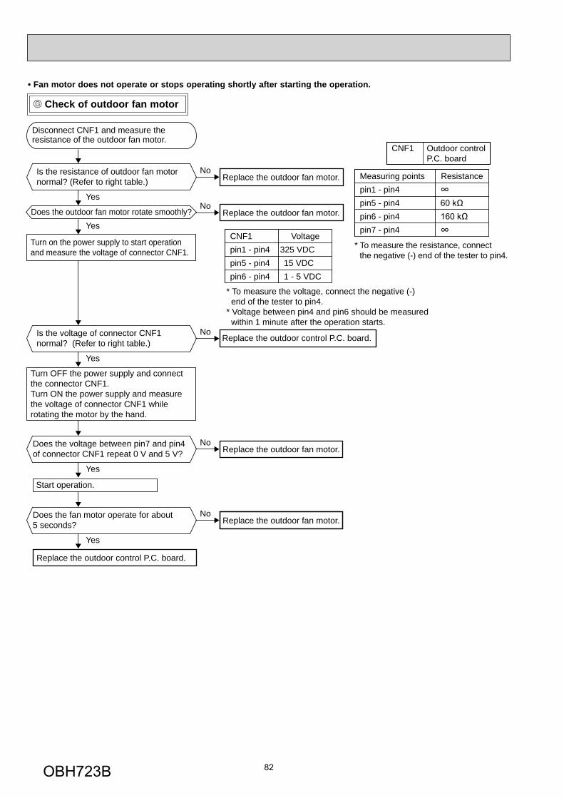
82
No
Yes
No
Yes
No
Yes
No
Yes
No
Yes
Disconnect CNF1 and measure the resistance of the outdoor fan motor.
Is the resistance of outdoor fan motor normal? (Refer to right table.)
Turn on the power supply to start operation and measure the voltage of connector CNF1.
Turn OFF the power supply and connect the connector CNF1.Turn ON the power supply and measure the voltage of connector CNF1 while rotating the motor by the hand.
Does the outdoor fan motor rotate smoothly?
Replace the outdoor fan motor. ResistanceMeasuring points
* To measure the resistance, connect the negative (-) end of the tester to pin4.
* To measure the voltage, connect the negative (-) end of the tester to pin4.* Voltage between pin4 and pin6 should be measured within 1 minute after the operation starts.
pin1 - pin4pin5 - pin4pin6 - pin4pin7 - pin4
Voltage
15 VDC325 VDC
1 - 5 VDC
CNF1pin1 - pin4pin5 - pin4pin6 - pin4
Is the voltage of connector CNF1normal? (Refer to right table.)
Does the voltage between pin7 and pin4 of connector CNF1 repeat 0 V and 5 V? Replace the outdoor fan motor.
Does the fan motor operate for about 5 seconds? Replace the outdoor fan motor.
Replace the outdoor fan motor.
Start operation.
Replace the outdoor control P.C. board.
Replace the outdoor control P.C. board.
Check of outdoor fan motor
• Fan motor does not operate or stops operating shortly after starting the operation.
CNF1 Outdoor controlP.C. board
OBH723B
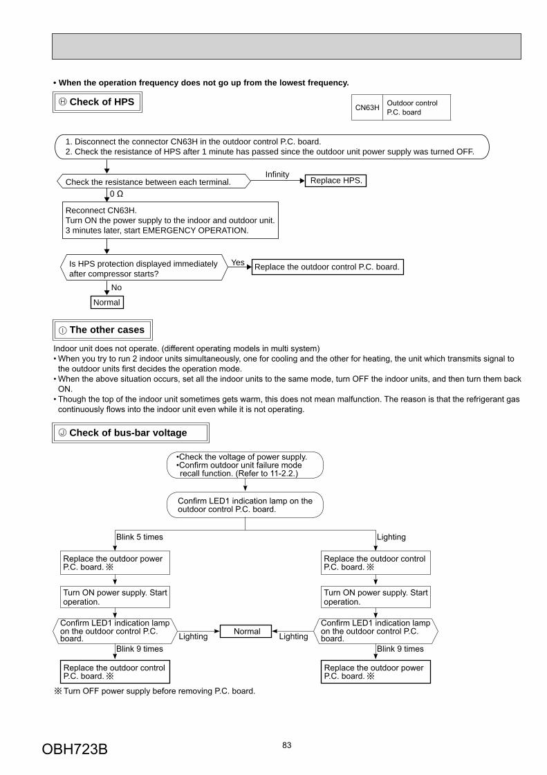
83
The other cases
• When the operation frequency does not go up from the lowest frequency.
Check of bus-bar voltage
•Check the voltage of power supply. •Confi rm outdoor unit failure mode recall function. (Refer to 11-2.2.)
Blink 5 times
Confi rm LED1 indication lamp on the outdoor control P.C. board.
Replace the outdoor power P.C. board.
Blink 9 times
Replace the outdoor control P.C. board.
Turn OFF power supply before removing P.C. board.
Confi rm LED1 indication lamp on the outdoor control P.C. board.
Turn ON power supply. Start operation.
Lighting
Replace the outdoor control P.C. board.
Blink 9 times
Replace the outdoor power P.C. board.
Confi rm LED1 indication lamp on the outdoor control P.C. board.
Turn ON power supply. Start operation.
NormalLighting Lighting
Check of HPS
Infinity
No
Yes
1. Disconnect the connector CN63H in the outdoor control P.C. board.2. Check the resistance of HPS after 1 minute has passed since the outdoor unit power supply was turned OFF.
Check the resistance between each terminal.
Reconnect CN63H.Turn ON the power supply to the indoor and outdoor unit.3 minutes later, start EMERGENCY OPERATION.
Is HPS protection displayed immediately after compressor starts?
Replace HPS.
Replace the outdoor control P.C. board.
Normal
CN63H Outdoor control P.C. board
Indoor unit does not operate. (different operating models in multi system)• When you try to run 2 indoor units simultaneously, one for cooling and the other for heating, the unit which transmits signal to the outdoor units fi rst decides the operation mode.
• When the above situation occurs, set all the indoor units to the same mode, turn OFF the indoor units, and then turn them back ON.
• Though the top of the indoor unit sometimes gets warm, this does not mean malfunction. The reason is that the refrigerant gas continuously fl ows into the indoor unit even while it is not operating.
OBH723B
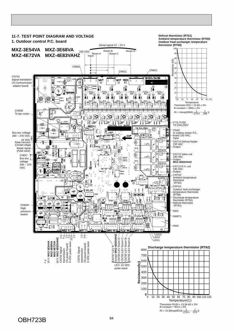
84
CN601
230 VDCRoom A
Input
Room BRoom C
Room D
CN930To fan motor
Defrost thermistor (RT61)
Discharge temperaturethermistor (RT62)
Outdoor heat exchangertemperature thermistor (RT68)
CNTH1
CNTH2Ambient temperature thermistor (RT65)
SW1
LED3
LEV: 12 VDC pulse wave
LED2LED1
SW2
SW871
CN712 R.V. coil230 VACOutput
CN713 Valve coil230 VACOutputMXZ-4E83VAHZ
CN714 Defrost heater230 VACOutput
CNAC to outdoor power P.C.board 230 VACInput
F711 FUSET3.15AL250V
CN611
Serial signal 12 ~ 24 V
CN621
CN741Signal translation(To Communication adaptor board)
CN
791
LEV
Roo
m A
(CN792 LEV
Roo
m B
CN
794
LEV
Roo
m D
CN
797
LEV
Rex
cept
MXZ
-4E8
3VA
HZ
(-)
CN
701
Sig
nal
trans
mis
sion
(To
pow
er b
oard
)5
VD
C p
ulse
wav
e
CN
702
Sig
nal
trans
mis
sion
(To
pow
er b
oard
)5
VD
C p
ulse
wav
e
CN
793
LEV
Roo
m C
(+)
(+)
(-)
(-)
15 V* V (-
)
CN63HHigh pressure switch
CNDCBus-bur voltage290 ~ 370 VDC
Bus-bur voltage290 ~ 370 VDC
18 VDCRotate instruction (Constant voltage)
Rotate signal (Pulse wave)
)* V 15
V: M
XZ-3
E54V
A
MXZ
-3E6
8VA
M
XZ-4
E72V
A18
V: M
XZ-4
E83V
AH
Z
0
100
200
300
400
500
600
700
800
0 10 20 30 40 50 60 70 80 90 100 110 120Temperature( )
Discharge temperature thermistor (RT62)
Res
ista
nce(
k )
Thermistor R100 = 13.36 k ± 2%B constant = 4014 ± 2%Rt = 13.36exp{4014( )}273+t
13731
-20 -10 0 10 20 30 40 (ºC)
100
90
80
70
60
50
40
30
20
10
0
Temperature
273+t1
2981
Thermistor R25 = 10 k ± 2%B constant = 3950 ± 2%
Rt = 10exp{3950( )}
Defrost thermistor (RT61)Ambient temperature thermistor (RT65)Outdoor heat exchanger temperature thermistor (RT68)
MXZ-3E54VA MXZ-3E68VAMXZ-4E72VA MXZ-4E83VAHZ
11-7. TEST POINT DIAGRAM AND VOLTAGE1. Outdoor control P.C. board
OBH723B
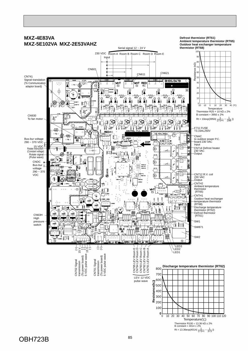
85
CN601
230 VDC Room AInput
Room B Room C Room D Room E
CN930To fan motor
Defrost thermistor (RT61)
Discharge temperaturethermistor (RT62)
Outdoor heat exchangertemperature thermistor (RT68)
CNTH1
CNTH2Ambient temperature thermistor (RT65)
SW1
LED3
LEV: 12 VDC pulse wave
LED2LED1
SW2
SW871
CN712 R.V. coil230 VACOutput
CNAC to outdoor power P.C.board 230 VACInput
F711 FUSET3.15AL250V
CN611
Serial signal 12 ~ 24 V
CN621CN741Signal translation(To Communication adaptor board)
CN
791
LEV
Roo
m A
(CN792 LE
V R
oom
B
CN
794
LEV
Roo
m D
CN
795
LEV
Roo
m E(-
)C
N70
1 S
igna
l tra
nsm
issi
on(T
o po
wer
boa
rd)
5 V
DC
pul
se w
ave
CN
702
Sig
nal
trans
mis
sion
(To
pow
er b
oard
)5
VD
C p
ulse
wav
e
CN
793
LEV
Roo
m C(+
)
(+)
(-)
(-)
15 V (-
)
CN63HHigh pressure switch
CNDCBus-bur voltage290 ~ 370 VDC
Bus-bur voltage290 ~ 370 VDC
15 VDCRotate instruction (Constant voltage)
Rotate signal (Pulse wave)
)15
V
CN714 Defrost heater230 VACOutput
0
100
200
300
400
500
600
700
800
0 10 20 30 40 50 60 70 80 90 100 110 120Temperature( )
Discharge temperature thermistor (RT62)
Res
ista
nce(
k )
Thermistor R100 = 13.36 k ± 2%B constant = 4014 ± 2%Rt = 13.36exp{4014( )}273+t
1373
1
-20 -10 0 10 20 30 40 (ºC)
100
90
80
70
60
50
40
30
20
10
0
Temperature
273+t1
2981
Thermistor R25 = 10 k ± 2%B constant = 3950 ± 2%
Rt = 10exp{3950( )}
Defrost thermistor (RT61)Ambient temperature thermistor (RT65)Outdoor heat exchanger temperature thermistor (RT68)
MXZ-4E83VAMXZ-5E102VA MXZ-2E53VAHZ
OBH723B
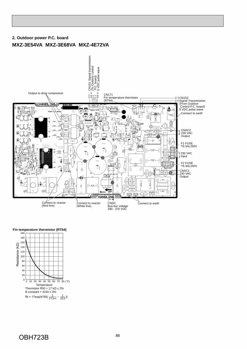
86
2. Outdoor power P.C. board
200
180
160
140
120
100
80
60
40
20
0
Temperature
Fin temperature thermistor (RT64)
Thermistor R50 = 17 k ± 2%B constant = 4150 ± 3%
273+t1
3231
0 10 20 30 40 50 60 70 80
MXZ-3E54VA MXZ-3E68VA MXZ-4E72VA
Output to drive compressor
Connect to earthConnect to reactor(Red line)
Connect to reactor(White line)
CNDCBus-bur voltage290 - 370 VDC
CNAC1230 VAC Output
F2 FUSET6.3AL250V
F1 FUSET6.3AL250V
230 VAC Input
CNAC2230 VAC Output
Connect to earth
CN152Signal Transmission(From Outdoor Control P.C. board)5 VDC pulse wave
(-)(+)
CN171Fin temperature thermistor(RT64)
CN
151
Sig
nal t
rans
mis
sion
(To
Out
door
con
trol
P.C
. boa
rd)
5 V
DC
pul
se w
ave
(+)
(-)
(-)
15
V
15
V
OBH723B
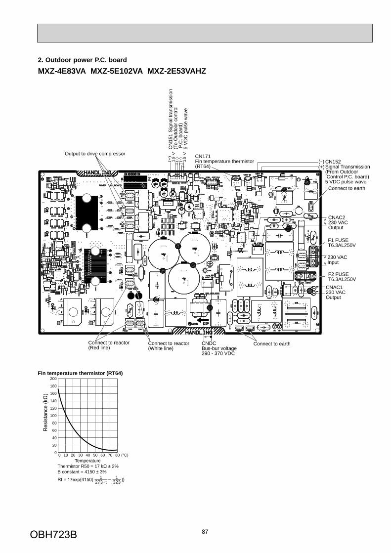
87
2. Outdoor power P.C. board
200
180
160
140
120
100
80
60
40
20
0
Temperature
Fin temperature thermistor (RT64)
Thermistor R50 = 17 k ± 2%B constant = 4150 ± 3%
273+t1
3231
0 10 20 30 40 50 60 70 80
Output to drive compressor
Connect to earthConnect to reactor(Red line)
Connect to reactor(White line)
CNDCBus-bur voltage290 - 370 VDC
CNAC1230 VAC Output
F2 FUSET6.3AL250V
F1 FUSET6.3AL250V
230 VAC Input
CNAC2230 VAC Output
Connect to earth
CN152Signal Transmission(From Outdoor Control P.C. board)5 VDC pulse wave
(-)(+)
CN171Fin temperature thermistor(RT64)
CN
151
Sig
nal t
rans
mis
sion
(To
Out
door
con
trol
P.C
. boa
rd)
5 V
DC
pul
se w
ave
(+)
(-)
(-)
15 V
15 V
MXZ-4E83VA MXZ-5E102VA MXZ-2E53VAHZ
OBH723B

88
MXZ-4E83VAHZ
200
180
160
140
120
100
80
60
40
20
0
Temperature
Fin temperature thermistor (RT64)
Thermistor R50 = 17 k ± 2%B constant = 4150 ± 3%
273+t1
3231
0 10 20 30 40 50 60 70 80
CN152Signal Transmission(From Outdoor Control P.C. board)5 VDC pulse wave
Output to drive compressor
CNDCBus-bur voltage290 - 370 VDCCN171
Fin temperature thermistor(RT64)
230 VAC InputCNAC2230 VAC Output
CNAC1230 V Output
Connect to earth
Connect to earth
Connect to earth
Connect to reactor(Red line)
F2 FUSET6.3AL250V
F1 FUSET6.3AL250V
Connect to reactor(White line)
(-)(+)
CN
151
Sig
nal t
rans
mis
sion
(To
Out
door
con
trol
P.C
. boa
rd)
5 V
DC
pul
se w
ave
(+)
(-)
(-)
15 V
15 V
18 V
OBH723B
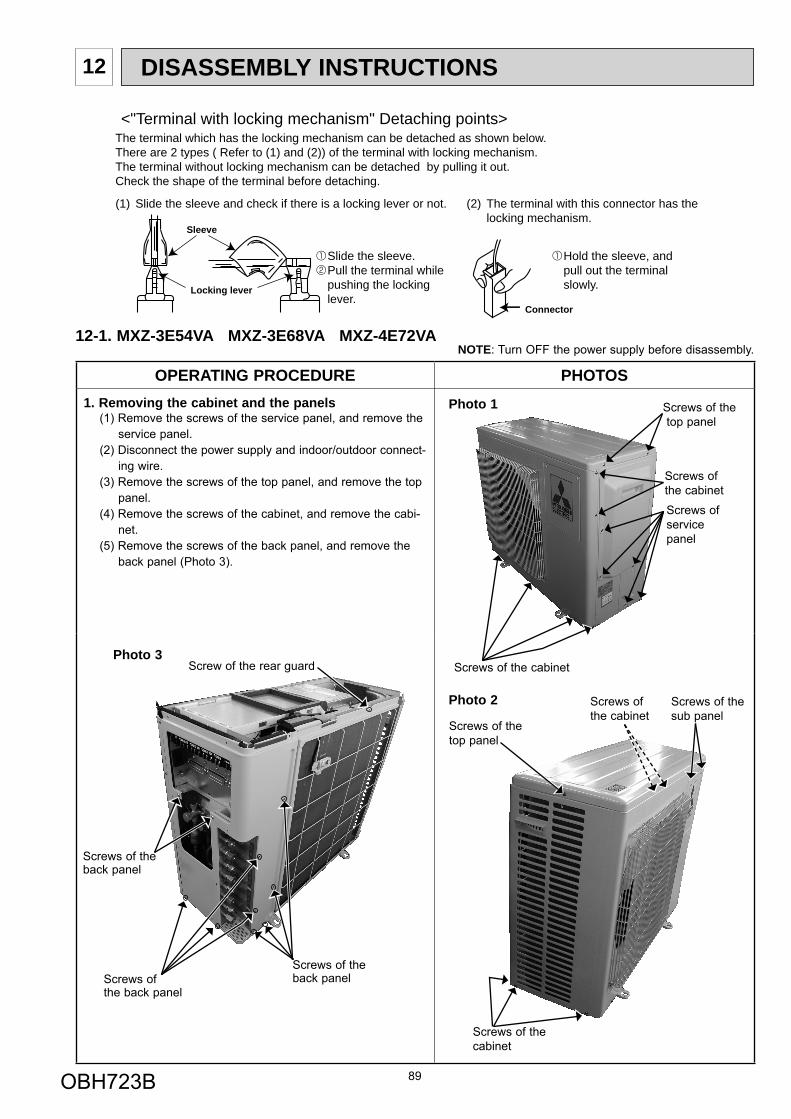
OPERATING PROCEDURE PHOTOS1. Removing the cabinet and the panels
(1) Remove the screws of the service panel, and remove the service panel.
(2) Disconnect the power supply and indoor/outdoor connect-ing wire.
(3) Remove the screws of the top panel, and remove the top panel.
(4) Remove the screws of the cabinet, and remove the cabi-net.
(5) Remove the screws of the back panel, and remove the back panel (Photo 3).
89
DISASSEMBLY INSTRUCTIONS12
(1) Slide the sleeve and check if there is a locking lever or not. (2) The terminal with this connector has the locking mechanism.
Slide the sleeve. Pull the terminal while pushing the locking lever.
Hold the sleeve, and pull out the terminal slowly.
The terminal which has the locking mechanism can be detached as shown below.There are 2 types ( Refer to (1) and (2)) of the terminal with locking mechanism.The terminal without locking mechanism can be detached by pulling it out.Check the shape of the terminal before detaching.
<"Terminal with locking mechanism" Detaching points>
Connector
Sleeve
Locking lever
12-1. MXZ-3E54VA MXZ-3E68VA MXZ-4E72VANOTE: Turn OFF the power supply before disassembly.
Photo 2
Photo 1
Screws of the cabinet
Screws of the top panel
Screws of the cabinetScrews of service panel
Screws of the top panel
Screws of the cabinet
Screws of the cabinet
Screws of thesub panel
Photo 3Screw of the rear guard
Screws of theback panel
Screws of the back panel
Screws ofthe back panel
OBH723B
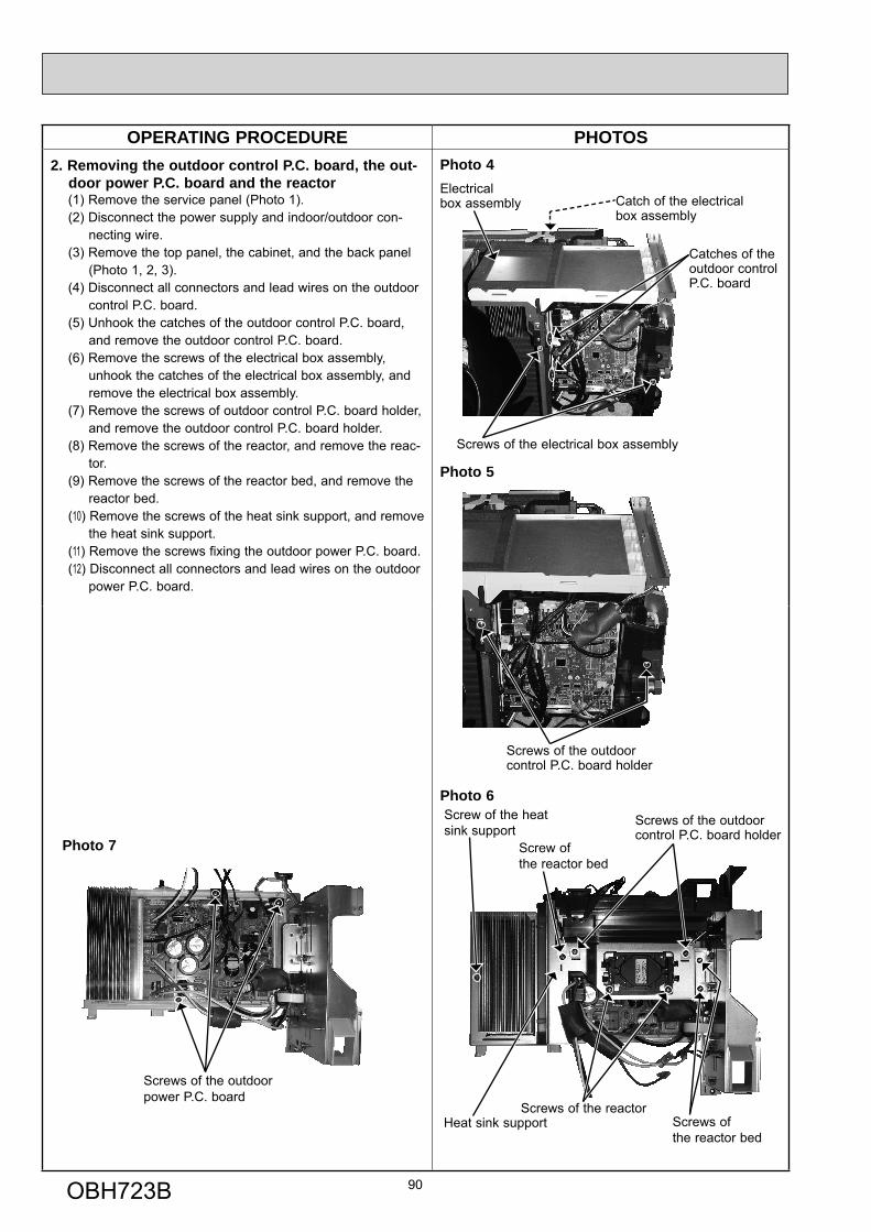
OPERATING PROCEDURE PHOTOS2. Removing the outdoor control P.C. board, the out-
door power P.C. board and the reactor(1) Remove the service panel (Photo 1).(2) Disconnect the power supply and indoor/outdoor con-
necting wire.(3) Remove the top panel, the cabinet, and the back panel
(Photo 1, 2, 3).(4) Disconnect all connectors and lead wires on the outdoor
control P.C. board.(5) Unhook the catches of the outdoor control P.C. board,
and remove the outdoor control P.C. board.(6) Remove the screws of the electrical box assembly,
unhook the catches of the electrical box assembly, and remove the electrical box assembly.
(7) Remove the screws of outdoor control P.C. board holder, and remove the outdoor control P.C. board holder.
(8) Remove the screws of the reactor, and remove the reac-tor.
(9) Remove the screws of the reactor bed, and remove the reactor bed.
(10) Remove the screws of the heat sink support, and remove the heat sink support.
(11) Remove the screws fixing the outdoor power P.C. board.(12) Disconnect all connectors and lead wires on the outdoor
power P.C. board.
90
Photo 4
Screws of the electrical box assembly
Electrical box assembly Catch of the electrical
box assembly
Catches of the outdoor control P.C. board
Photo 5
Screws of the outdoor control P.C. board holder
Screws of the outdoor control P.C. board holder
Photo 6
Photo 7
Screws of the reactor
Screws of the outdoor power P.C. board
Heat sink support
Screw of the heat sink support
Screws of the reactor bed
Screw of the reactor bed
OBH723B
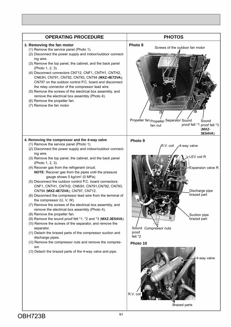
OPERATING PROCEDURE PHOTOS3. Removing the fan motor
(1) Remove the service panel (Photo 1).(2) Disconnect the power supply and indoor/outdoor connect-
ing wire.(3) Remove the top panel, the cabinet, and the back panel
(Photo 1, 2, 3).(4) Disconnect connectors CN712, CNF1, CNTH1, CNTH2,
CN63H, CN791, CN792, CN793, CN794 (MXZ-4E72VA), CN797 on the outdoor control P.C. board and disconnect the relay connector of the compressor lead wire.
(5) Remove the screws of the electrical box assembly, and remove the electrical box assembly (Photo 4).
(6) Remove the propeller fan.(7) Remove the fan motor.
Photo 8
4. Removing the compressor and the 4-way valve(1) Remove the service panel (Photo 1).(2) Disconnect the power supply and indoor/outdoor connect-
ing wire.(3) Remove the top panel, the cabinet, and the back panel
(Photo 1, 2, 3).(4) Recover gas from the refrigerant circuit.
NOTE: Recover gas from the pipes until the pressure gauge shows 0 kg/cm2 (0 MPa).
(5) Disconnect the outdoor control P.C. board connectors: CNF1, CNTH1, CNTH2, CN63H, CN791,CN792, CN793,
CN794 (MXZ-4E72VA), CN797, CN712.(6) Disconnect the compressor lead wire from the terminal of the compressor (U, V, W).(7) Remove the screws of the electrical box assembly, and
remove the electrical box assembly (Photo 4).(8) Remove the propeller fan.(9) Remove the sound proof felt *1, *2 and *3 (MXZ-3E54VA).(10) Remove the screws of the separator, and remove the
separator.(11) Detach the brazed parts of the compressor suction and
discharge pipes.(12) Remove the compressor nuts and remove the compres-
sor.(13) Detach the brazed parts of the 4-way valve and pipe.
Sound proof felt *2
91
Photo 9R.V. coil 4-way valve
LEV coil R
Expansion valve R
Suction pipebrazed part
Discharge pipe brazed part
Compressor nuts
4-way valve
R.V. coil
Photo 10
Brazed parts
Screws of the outdoor fan motor
Propeller fan Propeller fan nut
Separator Sound proof felt *1
Sound proof felt *3(MXZ-3E54VA)
OBH723B
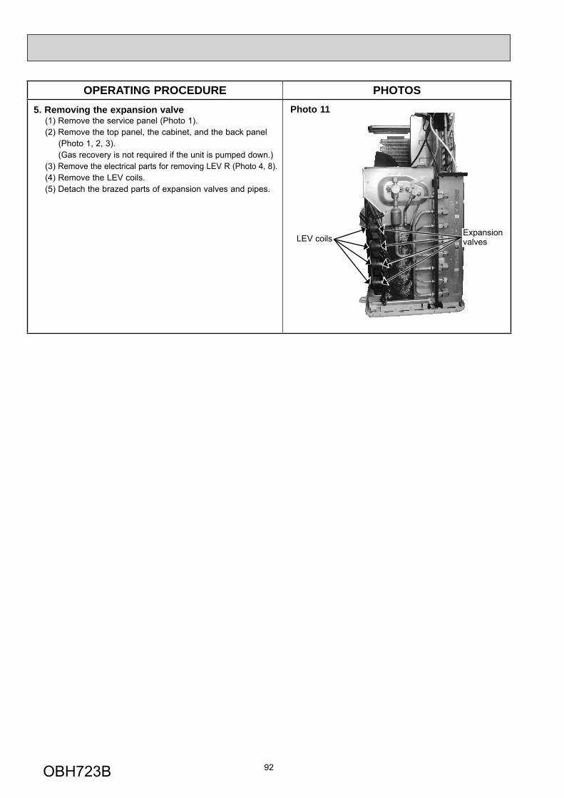
OPERATING PROCEDURE PHOTOS5. Removing the expansion valve
(1) Remove the service panel (Photo 1).(2) Remove the top panel, the cabinet, and the back panel
(Photo 1, 2, 3). (Gas recovery is not required if the unit is pumped down.)(3) Remove the electrical parts for removing LEV R (Photo 4, 8).(4) Remove the LEV coils.(5) Detach the brazed parts of expansion valves and pipes.
92
Expansion valves
Photo 11
LEV coils
OBH723B
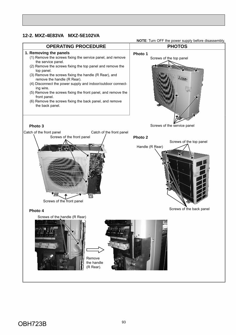
OPERATING PROCEDURE PHOTOS1. Removing the panels
(1) Remove the screws fixing the service panel, and remove the service panel.
(2) Remove the screws fixing the top panel and remove the top panel.
(3) Remove the screws fixing the handle (R Rear), and remove the handle (R Rear).
(4) Disconnect the power supply and indoor/outdoor connect-ing wire.
(5) Remove the screws fixing the front panel, and remove the front panel.
(6) Remove the screws fixing the back panel, and remove the back panel.
93
12-2. MXZ-4E83VA MXZ-5E102VANOTE: Turn OFF the power supply before disassembly.
Photo 1
Photo 3
Photo 4
Screws of the service panel
Screws of the front panel
Screws of the handle (R Rear)
Catch of the front panelCatch of the front panel
Screws of the top panel
Screws of the front panelScrews of the top panel
Screws of the back panel
Remove the handle (R Rear).
Photo 2
Handle (R Rear)
OBH723B
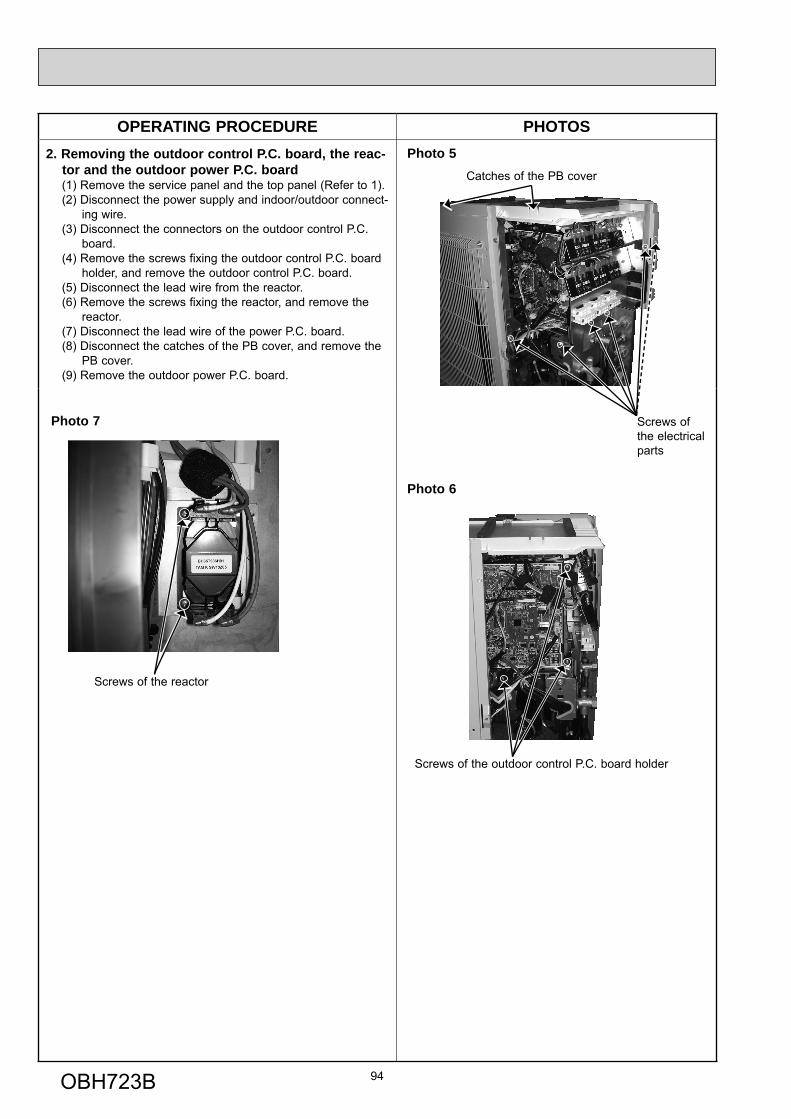
OPERATING PROCEDURE PHOTOS2. Removing the outdoor control P.C. board, the reac-
tor and the outdoor power P.C. board(1) Remove the service panel and the top panel (Refer to 1).(2) Disconnect the power supply and indoor/outdoor connect-
ing wire.(3) Disconnect the connectors on the outdoor control P.C.
board. (4) Remove the screws fixing the outdoor control P.C. board
holder, and remove the outdoor control P.C. board.(5) Disconnect the lead wire from the reactor.(6) Remove the screws fixing the reactor, and remove the
reactor.(7) Disconnect the lead wire of the power P.C. board.(8) Disconnect the catches of the PB cover, and remove the
PB cover.(9) Remove the outdoor power P.C. board.
94
Photo 5Catches of the PB cover
Photo 6
Screws of the outdoor control P.C. board holder
Screws of the reactor
Photo 7 Screws of the electrical parts
OBH723B
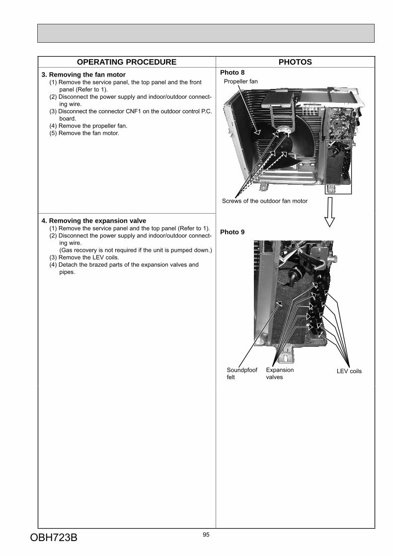
OPERATING PROCEDURE PHOTOS3. Removing the fan motor
(1) Remove the service panel, the top panel and the front panel (Refer to 1).
(2) Disconnect the power supply and indoor/outdoor connect-ing wire.
(3) Disconnect the connector CNF1 on the outdoor control P.C. board.
(4) Remove the propeller fan.(5) Remove the fan motor.
4. Removing the expansion valve(1) Remove the service panel and the top panel (Refer to 1).(2) Disconnect the power supply and indoor/outdoor connect-
ing wire. (Gas recovery is not required if the unit is pumped down.)(3) Remove the LEV coils.(4) Detach the brazed parts of the expansion valves and
pipes.
95
Photo 9
Photo 8Propeller fan
Screws of the outdoor fan motor
Expansion valves
LEV coilsSoundpfoof felt
OBH723B
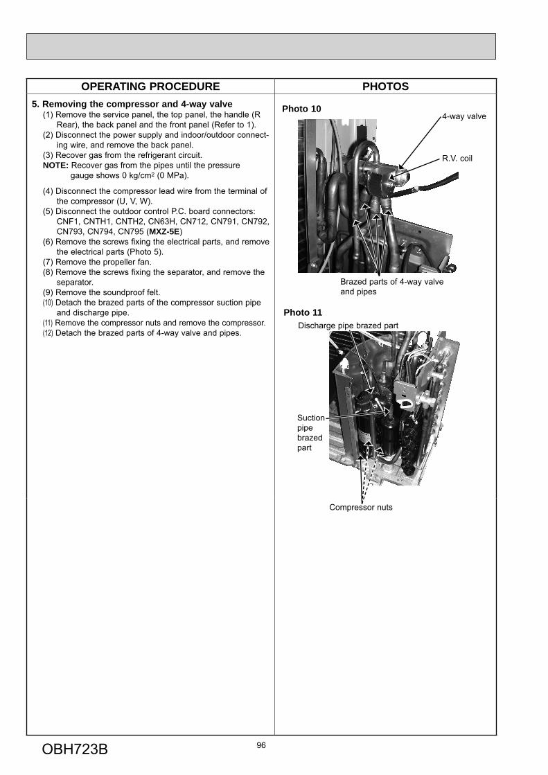
OPERATING PROCEDURE PHOTOS5. Removing the compressor and 4-way valve
(1) Remove the service panel, the top panel, the handle (R Rear), the back panel and the front panel (Refer to 1).
(2) Disconnect the power supply and indoor/outdoor connect-ing wire, and remove the back panel.
(3) Recover gas from the refrigerant circuit.NOTE: Recover gas from the pipes until the pressure gauge shows 0 kg/cm2 (0 MPa).
(4) Disconnect the compressor lead wire from the terminal of the compressor (U, V, W).(5) Disconnect the outdoor control P.C. board connectors: CNF1, CNTH1, CNTH2, CN63H, CN712, CN791, CN792, CN793, CN794, CN795 (MXZ-5E)(6) Remove the screws fixing the electrical parts, and remove
the electrical parts (Photo 5).(7) Remove the propeller fan.(8) Remove the screws fixing the separator, and remove the separator.(9) Remove the soundproof felt.(10) Detach the brazed parts of the compressor suction pipe
and discharge pipe.(11) Remove the compressor nuts and remove the compressor.(12) Detach the brazed parts of 4-way valve and pipes.
96
Photo 11
Suction pipe brazed part
Compressor nuts
Discharge pipe brazed part
4-way valve
R.V. coil
Brazed parts of 4-way valve and pipes
Photo 10
OBH723B
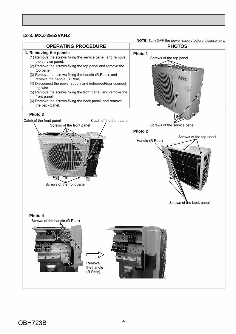
OPERATING PROCEDURE PHOTOS1. Removing the panels
(1) Remove the screws fixing the service panel, and remove the service panel.
(2) Remove the screws fixing the top panel and remove the top panel.
(3) Remove the screws fixing the handle (R Rear), and remove the handle (R Rear).
(4) Disconnect the power supply and indoor/outdoor connect-ing wire.
(5) Remove the screws fixing the front panel, and remove the front panel.
(6) Remove the screws fixing the back panel, and remove the back panel.
97
12-3. MXZ-2E53VAHZNOTE: Turn OFF the power supply before disassembly.
Photo 1
Photo 3
Photo 4
Screws of the service panel
Screws of the front panel
Screws of the handle (R Rear)
Catch of the front panelCatch of the front panel
Screws of the top panel
Screws of the front panel
Screws of the top panel
Screws of the back panel
Remove the handle (R Rear).
Photo 2
Handle (R Rear)
OBH723B
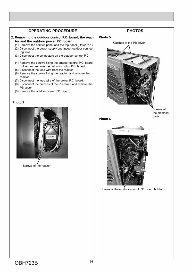
OPERATING PROCEDURE PHOTOS2. Removing the outdoor control P.C. board, the reac-
tor and the outdoor power P.C. board(1) Remove the service panel and the top panel (Refer to 1).(2) Disconnect the power supply and indoor/outdoor connect-
ing wire.(3) Disconnect the connectors on the outdoor control P.C.
board. (4) Remove the screws fixing the outdoor control P.C. board
holder, and remove the outdoor control P.C. board.(5) Disconnect the lead wire from the reactor.(6) Remove the screws fixing the reactor, and remove the
reactor.(7) Disconnect the lead wire of the power P.C. board.(8) Disconnect the catches of the PB cover, and remove the
PB cover.(9) Remove the outdoor power P.C. board.
98
Photo 5Catches of the PB cover
Photo 6
Screws of the outdoor control P.C. board holder
Screws of the reactor
Photo 7
Screws of the electrical parts
OBH723B
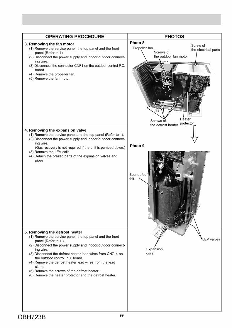
OPERATING PROCEDURE PHOTOS3. Removing the fan motor
(1) Remove the service panel, the top panel and the front panel (Refer to 1).
(2) Disconnect the power supply and indoor/outdoor connect-ing wire.
(3) Disconnect the connector CNF1 on the outdoor control P.C. board.
(4) Remove the propeller fan.(5) Remove the fan motor.
4. Removing the expansion valve(1) Remove the service panel and the top panel (Refer to 1).(2) Disconnect the power supply and indoor/outdoor connect-
ing wire. (Gas recovery is not required if the unit is pumped down.)(3) Remove the LEV coils.(4) Detach the brazed parts of the expansion valves and
pipes.
5. Removing the defrost heater(1) Remove the service panel, the top panel and the front
panel (Refer to 1.).(2) Disconnect the power supply and indoor/outdoor connect-
ing wire.(3) Disconnect the defrost heater lead wires from CN714 on
the outdoor control P.C. board.(4) Remove the defrost heater lead wires from the lead
clamp.(5) Remove the screws of the defrost heater.(6) Remove the heater protector and the defrost heater.
99
Photo 9
Photo 8Propeller fan
Heater protector
Screws of the outdoor fan motor
Screws of the defrost heater
Expansion coils
LEV valves
Soundpfoof felt
Screw of the electrical parts
OBH723B
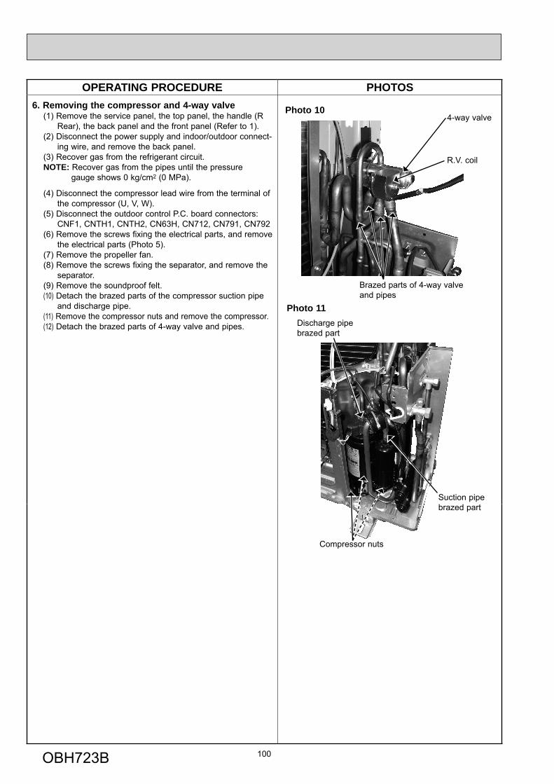
OPERATING PROCEDURE PHOTOS6. Removing the compressor and 4-way valve
(1) Remove the service panel, the top panel, the handle (R Rear), the back panel and the front panel (Refer to 1).
(2) Disconnect the power supply and indoor/outdoor connect-ing wire, and remove the back panel.
(3) Recover gas from the refrigerant circuit.NOTE: Recover gas from the pipes until the pressure gauge shows 0 kg/cm2 (0 MPa).
(4) Disconnect the compressor lead wire from the terminal of the compressor (U, V, W).(5) Disconnect the outdoor control P.C. board connectors: CNF1, CNTH1, CNTH2, CN63H, CN712, CN791, CN792(6) Remove the screws fixing the electrical parts, and remove
the electrical parts (Photo 5).(7) Remove the propeller fan.(8) Remove the screws fixing the separator, and remove the separator.(9) Remove the soundproof felt.(10) Detach the brazed parts of the compressor suction pipe
and discharge pipe.(11) Remove the compressor nuts and remove the compressor.(12) Detach the brazed parts of 4-way valve and pipes.
100
Photo 11
Suction pipe brazed part
Compressor nuts
Discharge pipe brazed part
4-way valve
R.V. coil
Brazed parts of 4-way valve and pipes
Photo 10
OBH723B
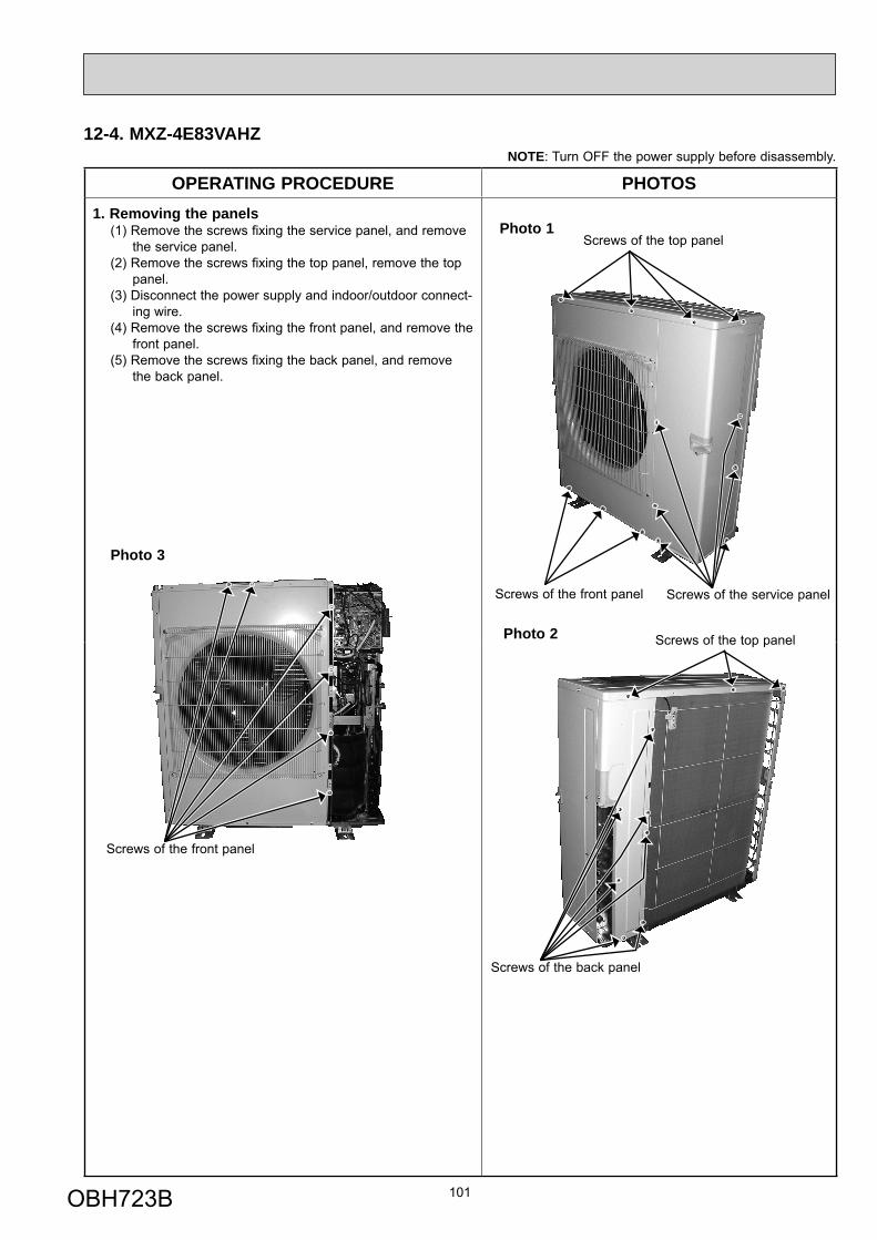
12-4. MXZ-4E83VAHZNOTE: Turn OFF the power supply before disassembly.
OPERATING PROCEDURE PHOTOS1. Removing the panels
(1) Remove the screws fixing the service panel, and remove the service panel.
(2) Remove the screws fixing the top panel, remove the top panel.
(3) Disconnect the power supply and indoor/outdoor connect-ing wire.
(4) Remove the screws fixing the front panel, and remove the front panel.
(5) Remove the screws fixing the back panel, and remove the back panel.
101
Photo 1
Screws of the service panelScrews of the front panel
Screws of the top panel
Screws of the top panel
Screws of the back panel
Photo 2
Photo 3
Screws of the front panel
OBH723B
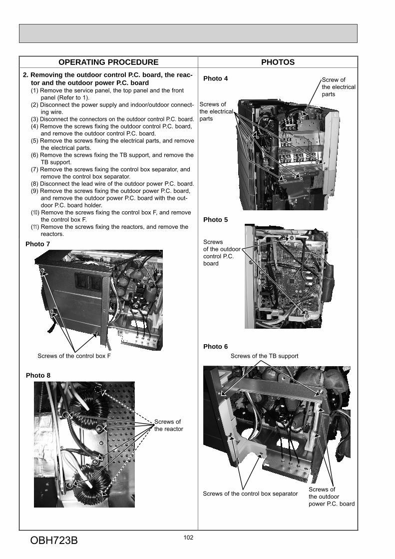
OPERATING PROCEDURE PHOTOS2. Removing the outdoor control P.C. board, the reac-
tor and the outdoor power P.C. board(1) Remove the service panel, the top panel and the front
panel (Refer to 1).(2) Disconnect the power supply and indoor/outdoor connect-
ing wire.(3) Disconnect the connectors on the outdoor control P.C. board.(4) Remove the screws fixing the outdoor control P.C. board,
and remove the outdoor control P.C. board.(5) Remove the screws fixing the electrical parts, and remove
the electrical parts.(6) Remove the screws fixing the TB support, and remove the
TB support.(7) Remove the screws fixing the control box separator, and
remove the control box separator.(8) Disconnect the lead wire of the outdoor power P.C. board. (9) Remove the screws fixing the outdoor power P.C. board,
and remove the outdoor power P.C. board with the out-door P.C. board holder.
(10) Remove the screws fixing the control box F, and remove the control box F.
(11) Remove the screws fixing the reactors, and remove the reactors.
102
Photo 4
Screws of the electrical parts
Photo 5
Screws of the outdoor control P.C. board
Photo 6
Screws of the outdoor power P.C. board
Screws of the control box separator
Screws of the TB supportScrews of the control box F
Photo 7
Photo 8
Screws of the reactor
Screw of the electrical parts
OBH723B
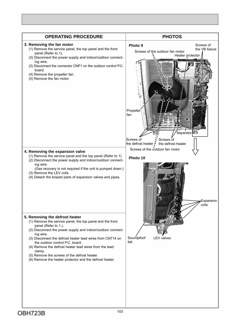
OPERATING PROCEDURE PHOTOS3. Removing the fan motor
(1) Remove the service panel, the top panel and the front panel (Refer to 1).
(2) Disconnect the power supply and indoor/outdoor connect-ing wire.
(3) Disconnect the connector CNF1 on the outdoor control P.C. board.
(4) Remove the propeller fan.(5) Remove the fan motor.
4. Removing the expansion valve(1) Remove the service panel and the top panel (Refer to 1).(2) Disconnect the power supply and indoor/outdoor connect-
ing wire. (Gas recovery is not required if the unit is pumped down.)(3) Remove the LEV coils.(4) Detach the brazed parts of expansion valves and pipes.
5. Removing the defrost heater(1) Remove the service panel, the top panel and the front
panel (Refer to 1.).(2) Disconnect the power supply and indoor/outdoor connect-
ing wire.(3) Disconnect the defrost heater lead wires from CN714 on
the outdoor control P.C. board.(4) Remove the defrost heater lead wires from the lead
clamp.(5) Remove the screws of the defrost heater.(6) Remove the heater protector and the defrost heater.
103
Photo 10
Photo 9
Propeller fan
Separator
Screws of the outdoor fan motor
Screws of the outdoor fan motor
Screws of the VB fixture
LEV valves
Expansion coils
Soundpfoof felt
Heater protector
Screws of the defrost heater
Screws of the defrost heater
OBH723B
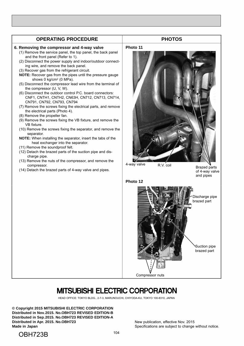
OPERATING PROCEDURE PHOTOS6. Removing the compressor and 4-way valve
(1) Remove the service panel, the top panel, the back panel and the front panel (Refer to 1).
(2) Disconnect the power supply and indoor/outdoor connect-ing wire, and remove the back panel.
(3) Recover gas from the refrigerant circuit.NOTE: Recover gas from the pipes until the pressure gauge
shows 0 kg/cm2 (0 MPa).(5) Disconnect the compressor lead wire from the terminal of
the compressor (U, V, W).(6) Disconnect the outdoor control P.C. board connectors: CNF1, CNTH1, CNTH2, CN63H, CN712, CN713, CN714,
CN791, CN792, CN793, CN794(7) Remove the screws fixing the electrical parts, and remove
the electrical parts (Photo 4).(8) Remove the propeller fan.(9) Remove the screws fixing the VB fixture, and remove the
VB fixture.(10) Remove the screws fixing the separator, and remove the
separator.NOTE: When installing the separator, insert the tabs of the
heat exchanger into the separator.(11) Remove the soundproof felt.(12) Detach the brazed parts of the suction pipe and dis-
charge pipe.(13) Remove the nuts of the compressor, and remove the
compressor.(14) Detach the brazed parts of 4-way valve and pipes.
104
HEAD OFFICE: TOKYO BLDG., 2-7-3, MARUNOUCHI, CHIYODA-KU, TOKYO 100-8310, JAPAN
© Copyright 2015 MITSUBISHI ELECTRIC CORPORATIONDistributed in Nov. 2015. No.OBH723 REVISED EDITION-BDistributed in Sep. 2015. No.OBH723 REVISED EDITION-ADistributed in Apr. 2015. No.OBH723 Made in Japan
New publication, effective Nov. 2015Specifications are subject to change without notice.
4-way valve R.V. coil Brazed parts of 4-way valve and pipes
Photo 11
Photo 12
Suction pipe brazed part
Compressor nuts
Discharge pipe brazed part
OBH723B