jornada tecnica semr 2015
TRANSCRIPT

7/23/2019 Jornada Tecnica Semr 2015
http://slidepdf.com/reader/full/jornada-tecnica-semr-2015 1/77
LA MECÁNICA DE ROCAS
EN EL EUROCÓDIGO 7 Y
OTRAS NORMATIVAS
Con la colaboración de: J O R N
A D A T É C N I C A S E M R 2 0 1 5

7/23/2019 Jornada Tecnica Semr 2015
http://slidepdf.com/reader/full/jornada-tecnica-semr-2015 2/77

7/23/2019 Jornada Tecnica Semr 2015
http://slidepdf.com/reader/full/jornada-tecnica-semr-2015 3/77
JORNADA TÉCNICA
SEMR 2015
La Mecánica de Rocas en elEurocódigo 7 y otras
normativas
15 de abril de 2015
7/23/2019 Jornada Tecnica Semr 2015
http://slidepdf.com/reader/full/jornada-tecnica-semr-2015 4/77
PRESENTACIÓN
La Sociedad Española de Mecánica de Rocas (SEMR) organiza un
año más su Jornada Técnica anual, conjuntamente con el Centrode Estudios y Experimentación de Obras Públicas (CEDEX).
En la última década se ha realizado en España un gran esfuerzo
normativo en el ámbito de la ingeniería geotécnica que dio lugar
a la publicación de la Guía de Cimentaciones de Obras de
Carreteras (2003), la parte geotécnica de las Recomendaciones
para Obras Marítimas 0.5-05 (2005) y la parte referida a las
cimentaciones del Código Técnico de la Edificación. De forma
simultánea, en Europa se publicó en 2004 el Eurocódigo 7“Proyecto Geotécnico” (EC-7) que se ha ido utilizando
paulatinamente en los diferentes países europeos.
Actualmente, está a punto de empezar el proceso para la
elaboración de la segunda generación de Eurocódigos para lo
cual el comité responsable del EC-7 ha creado varios grupos de
trabajo entre los que destaca, en este ámbito, uno dedicado a la
Mecánica de Rocas, apoyado también por la ISRM. El objetivo
del grupo es determinar los aspectos de la Ingeniería de Rocas
susceptibles de ser incluidos en el nuevo Eurocódigo EC-7.
En este contexto, la SEMR ha considerado interesante dedicar la
Jornada Técnica de este año a realizar un análisis de los aspectos
dedicados a la Mecánica de Rocas en dichos documentos
normativos, para lo cual se contará con la presencia de
destacados profesionales con amplia experiencia en estos
temas.Por último, se debe destacar que durante la celebración de la
Jornada se nombrará Socio de Honor de la SEMR a D. Luis
González de Vallejo, por sus destacadas aportaciones a la
Mecánica de Rocas.
Asimismo, se realizará entrega de la 6º edición del Premio al
mejor trabajo en Mecánica de Rocas para jóvenes
investigadores.
7/23/2019 Jornada Tecnica Semr 2015
http://slidepdf.com/reader/full/jornada-tecnica-semr-2015 5/77
PROGRAMA
8,30 - 9,00 Inscripciones y documentación
9,00 - 9,15 Presentación de la Jornada
D. Mariano Navas Gutiérrez
Director del CEDEX
D. Fernando Pardo de Santayana
Director del Laboratorio de Geotecnia del CEDEX
9,15 - 10.00 Algunos aspectos relacionados con la mecánica de rocas en los documentos
normativos geotécnicos españoles y en el Eurocódigo 7
D. José Estaire Gepp
Laboratorio de Geotecnia (CEDEX). Universidad Politécnica de Madrid
Secretario del Subcomité español del EC-7
10,00 - 10,45 Los valores característicos de los parámetros geotécnicos de las rocas.
D. Alberto Bernal Riosalido
ByA Estudio de Ingeniería S.L.
Universidad Politécnica de Madrid
10,45 - 11,00
Entrega de placa de Socio de Honor de la SEMR al profesor
D. Luis González de Vallejo .
11,00-11,25 Pausa, café
11,25-11,45
Entrega del 6º Premio al mejor trabajo de investigación en Mecánica de
Rocas para jóvenes. Breve exposición del mismo.
11,45 -12,30 Current issues concerning application of Eurocode 7 to rock engineering
Dr. Luís Lamas
Jefe del Área de Modelación y Mecánica de Rocas. Laboratório Nacional deIngeniería Civil (LNEC), Lisboa
Secretario General de la ISRM
12,30 - 13,30 Eurocode 7 and rock engineering: problems and opportunities
Professor John Harrison
Keck Chair of Engineering Rock Mechanics. Toronto University.
Presidente del grupo de trabajo del EC-7 relativo a la Mecánica de Rocas
13,30 -14,00 Mesa Redonda y Clausura
Coordinadores:
D. Áurea Perucho Laboratorio de Geotecnia del CEDEX
D. Javier González-Gallego Laboratorio de Geotecnia del CEDEX

7/23/2019 Jornada Tecnica Semr 2015
http://slidepdf.com/reader/full/jornada-tecnica-semr-2015 6/77
ÍNDICE DE PONENCIAS
“ Algunos aspectos relacionados con la mecánica de rocas en los documentos
normativos geotécnicos españoles y en el Eurocódigo 7”
D. José Estaire Gepp
Laboratorio de Geotecnia (CEDEX). Universidad Politécnica de Madrid
Secretario del Subcomité español del EC-7
“ Los valores característicos de los parámetros geotécnicos de las rocas”
D. Alberto Bernal Riosalido
ByA Estudio de Ingeniería S.L.
Universidad Politécnica de Madrid
“ Current issues concerning application of Eurocode 7 to rock engineering”
Dr. Luís Lamas
Jefe del Área de Modelación y Mecánica de Rocas. Laboratório Nacional de Ingeniería Civil(LNEC), Lisboa
Secretario General de la ISRM
“ Eurocode 7 and rock engineering: problems and opportunities”
Professor John Harrison
Keck Chair of Engineering Rock Mechanics. Toronto University.
Presidente del grupo de trabajo del EC-7 relativo a la Mecánica de Rocas

7/23/2019 Jornada Tecnica Semr 2015
http://slidepdf.com/reader/full/jornada-tecnica-semr-2015 7/77

7/23/2019 Jornada Tecnica Semr 2015
http://slidepdf.com/reader/full/jornada-tecnica-semr-2015 8/77
SEMR
JORNADA TÉCNICA 2015EL EUROCÓDIGO 7 Y OTRAS NORMATIVAS
Algunos aspectos relacionados con la mecánica de rocas en
los documentos normativos geotécnicos españoles y en elEurocódigo 7
D. José Estaire Gepp
Laboratorio de Geotecnia (CEDEX).
Universidad Politécnica de Madrid
Secretario del Subcomité español del EC-7

7/23/2019 Jornada Tecnica Semr 2015
http://slidepdf.com/reader/full/jornada-tecnica-semr-2015 9/77
1
ALGUNOS ASPECTOS RELACIONADOS CON LAMECÁNICA DE ROCAS EN LOS DOCUMENTOSNORMATIVOS GEOTÉCNICOS ESPAÑOLES Y EN ELEUROCÓDIGO 7
José Estaire y Áurea PeruchoLaboratorio de Geotecnia – CEDEX
1. INTRODUCCIÓN: DOCUMENTOS NORMATIVOS DE ÍNDOLE GEOTÉCNICAVIGENTES EN ESPAÑA
En España existen actualmente tres documentos normativos de índole
geotécnico:
Guía de Cimentaciones en Obras de Carretera (GCOC), de aplicación
en el ámbito de carreteras, aprobado en 2003 por la Dirección General
de Carreteras del Ministerio de Fomento.
Recomendaciones para Obras Marítimas 0.5-05 (ROM),
“Recomendaciones Geotécnicas para Obras Marítimas y Portuarias”,
aprobado en 2005 por el ente Puertos del Estado, dependiente del
Ministerio de Fomento.
Documento Básico SE-C del Código Técnico de la Edificación
“Seguridad estructural. Cimientos” (CTE), de aplicación en la edificación,
aprobado en 2006 por el entonces Ministerio de la Vivienda.
Como es sabido, aunque únicamente el CTE es de obligado cumplimiento, los
otros dos documentos son ampliamente utilizados en sus respectivos ámbitos.
Adicionalmente, España ha adoptado asimismo el marco normativo de los
Eurocódigos, dentro de los cuales el EN-1997, conocido como “Eurocódigo 7”
(EC-7), hace referencia al proyecto geotécnico. Esta norma consta de dos
partes, la primera de las cuales –“General rules”- fue aprobada en 2004 y la
segunda –“Ground investigation and testing”- en 2007. Para la implementación
de esta norma en los diferentes países ha sido preciso que cada uno de ellos
redacte un Anejo Nacional en el que se definen y concretan una serie de
aspectos y parámetros que el EC-7 deja abiertos para que cada país escoja losque se consideren más convenientes, en función de la forma tradicional de

7/23/2019 Jornada Tecnica Semr 2015
http://slidepdf.com/reader/full/jornada-tecnica-semr-2015 10/77
2
proceder o de las consideraciones que se estimen convenientes. El Anejo
español al EC-7 fue redactado a lo largo del año 2013 por un Comité con sede
en el CEDEX, al que pertenecen los autores de este artículo, y se encuentra
actualmente a la espera de la aprobación definitiva por parte de los organismos
competentes. Las bases teóricas y conceptuales de dicho Anejo se pueden
consultar en Estaire et al (2014).
No obstante, tal y como ocurre con las demás normativas europeas, el EC-7 ha
de ser sometido a revisiones periódicas y actualmente existe un mandato de la
Comisión Europea para que se estudie la evolución de los diferentes
Eurocódigos con vista a producir unas nuevas versiones de los mismos dentro
del horizonte del año 2020, que presenten una mayor armonización.
Fundamentalmente, y en concreto en el EC-7, se persigue ir reduciendo las
diferencias de cálculo reflejadas en los Anejos Nacionales de los diferentes
países, además de tender hacia diseños menos conservadores y más
económicos, y de abordar aspectos de la ingeniería del terreno poco
contemplados en la versión vigente de la norma, como es el caso de la
mecánica de rocas y de la mejora y refuerzo del terreno.
Para llevar a cabo esta evolución del EC-7 se formaron hace aproximadamente
cuatro años una serie de grupos de trabajo, denominados “Evolution Groups”
(EG) (Orr, 2012) con la misión principal de establecer objetivos claros y definir
los diferentes aspectos a considerar. Tras varios años de trabajo estos grupos
han ido reflejando sus consideraciones y conclusiones en diferentes
documentos que servirán de apoyo al futuro grupo redactor de la nueva versión
del EC-7, a ser constituido en los primeros meses del año 2015.
Los autores de este artículo pertenecen a varios de los mencionados “Evolution
Groups”, uno de los cuales es el “EG-13, Rock Mechanics”, encargado deponer de manifiesto las carencias existentes relativas a la mecánica de rocas
en la actual versión del EC-7, así como de realizar las propuestas que se
consideren adecuadas para futuras versiones de la normativa.
Por otra parte, en el último congreso europeo de la ISRM, Eurock 2014, que
tuvo lugar en Vigo en mayo de 2014, se celebró un seminario sobre la
aplicabilidad del EC-7 al diseño en ingeniería de rocas (Workshop Eurock
2014), en el que se presentaron artículos relacionados con diversos temas derelevancia en la mecánica de rocas y sus problemas y dificultades en relación a

7/23/2019 Jornada Tecnica Semr 2015
http://slidepdf.com/reader/full/jornada-tecnica-semr-2015 11/77
3
la forma de abordarlos tanto en la versión vigente como en futuras versiones
del EC-7. Se puso de manifiesto que las principales dificultades a la hora de
abordar los problemas relacionados con la mecánica de rocas en el EC-7, o en
cualquier otra normativa, están relacionadas con el hecho de que el macizo
rocoso es un medio discontinuo, anisótropo y heterogéneo, a diferencia de la
mayoría de los suelos que, en general, pueden ser considerados medios
continuos, isótropos y homogéneos, aunque estrictamente tampoco lo sean.
Harrison (2014) presenta una interesante recopilación y reflexión acerca de
este tema.
Teniendo en cuenta estos antecedentes, en este artículo se realiza un análisis
comparativo de los principales aspectos contemplados en los distintos
documentos normativos vigentes en España, relativos a la mecánica de rocas,
poniendo de manifiesto similitudes y diferencias, así como algunas reflexiones
y propuestas tentativas, con el objetivo de tratar de buscar elementos que
puedan ayudar a enfocar y a definir aspectos relacionados con la mecánica de
rocas en futuras versiones de la normativa europea. Este texto se ha centrado
exclusivamente en la forma de abordar la estimación de las cargas admisibles
de cimentaciones superficiales y profundas. Muchos de estos aspectos han
sido recogidos anteriormente en Perucho y Estaire (2014).
2. ANÁLISIS COMPARATIVO DE LOS PRINCIPALES ASPECTOS RELATIVOS ALAS CIMENTACIONES SUPERFICIALES Y PROFUNDAS
2.1. Aplicabilidad de los métodos de cálculo de suelos
Cabe resaltar que los tres documentos indican que la roca se puede considerarcomo un suelo en ciertos casos, aunque cada uno de ellos adopta un criterio
diferente para ello, como se recoge en la Tabla I.

7/23/2019 Jornada Tecnica Semr 2015
http://slidepdf.com/reader/full/jornada-tecnica-semr-2015 12/77
4
Tabla I. Criterios empleados para considerar el macizo rocoso como unsuelo
Parámetro CTE GCOC ROM
Grado de alteración > IV ≥ IV ≥ IV
Resistencia a compression simpleUCS (MPa) < 2,5 < 1 ---
Espaciamiento de juntas (cm) --- --- < 10 cm
RQD (%) < 25 < 10 < 10
Nota: Es suficiente con que se cumpla uno de los criterios
Como se puede apreciar los tres están de acuerdo en considerar el macizo
rocoso como un suelo para grados de alteración superiores a III, pero mientras
la GCOC y la ROM consideran suelo para valores del RQD inferiores al 10%, el
CTE lo hace cuando dicho valor es inferior al 25%. Por otra parte, en relación a
la resistencia a compresión simple el CTE pone el límite en 2,5 MPa mientras
que la GCOC lo pone en 1 MPa y la ROM no indica ningún valor de este
parámetro, sino un espaciamiento de diaclasas inferior a 10 cm, que los otros
dos documentos no consideran.
2.2. Capacidad portante de las cimentaciones superficiales y profundas
en roca
En la Tabla II se indican las expresiones utilizadas para la determinación de la
capacidad portante de las cimentaciones superficiales en roca y se resumen los
principales aspectos contemplados en los tres documentos normativos.

7/23/2019 Jornada Tecnica Semr 2015
http://slidepdf.com/reader/full/jornada-tecnica-semr-2015 13/77
5
T a b l a I I . C a p a c i d a d p o r t a n
t e d e u n a c i m e n t a c i ó n s u p e r f i c i a l e n
r o c a .
R e s u m e n d e p r i n c i p a l e s a s p e c
t o s c o n t e m p l a d o s e n
l o s t r e s d o c u m e n t o s n o r m
a t i v o s
D o c u m e n t o
C a p a c i d a d p o r t a n t e e n r o c a , q a
D e p e n d e d e
O b s e r v a c i o n e s
G C O C
p r = 1 M P a ( p r e s i ó n d e r e f e r e n c i a )
2 = 1 ( W D = I ) ; 0 , 7 ( W D = I I ) ; 0 , 5
( W D = I I I )
3 = m i n (
1 ⁄
,
1 0 0
⁄
)
4 = ( 1 , 1 - t g ) 3 (
4 = 1 s i t g > 0 , 1 0 )
- U C S : r e s i s t e n c i a a c o m p r e s i ó n s i m p l e .
- q t : r e s i s t e n c i a a t r a c c i ó
n s i m p l e .
- s : s e p a r a c i ó n d e d i a c l a s a s .
- W D : g r a d o d e a l t e r a c i ó n .
- R Q D : r o c k q u a l i t y d e s i g n .
- : i n c l i n a c i ó n d e l a c a r g a .
- q a
< 5 M P a s a l v o j u s t i f i c a c i ó n .
- T e r r e n o h o r i z o n t a l ( p e n
d i e n t e < 1 0 % ) .
- Á r e a d e c i m e n t a c i ó n <
1 0 0 m
2 .
- G r a d i e n t e s d e a g u a < 2
, 2 .
R O M
=
=
3 √
p r = 1 M P a ( p r e s i ó n d e r e f e r e n c i a )
f D = m i n ( 2
∗
⁄
≤ 1
; 0
, 2
∗
⁄
< 1 )
f A = 1 ( W D = I ) ; 0 , 7 (
W D = I I ) ; 0 , 5
( W D = I I I )
f D = ( 1 , 1 - t g ) 3 < 1
F S = 2 , 8
( p e r m a n e n t e ) ; 2 , 3
( f u n d a m e n t a l ) ;
2 , 1
( a c c i d e n t a l )
- U C S : r e s i s t e n c i a a c o m p r e s i ó n s i m p l e .
- s : s e p a r a c i ó n d e d i a c l a s a s .
- B * : a n c h o d e z a p a t a .
- W D : g r a d o d e a l t e r a c i ó n .
- R Q D : r o c k q u a l i t y d e s i g n .
- : i n c l i n a c i ó n d e l a c a r g a .
- q u l t < 1 5 M P a s a l v o j u s t i f i c a c i ó n .
- T e r r e n o h o r i z o n t a l ( p e n
d i e n t e < 1 0 % ) .
- Á r e a d e c i m e n t a c i ó n <
1 0 0 m
2 .
- S i e s t á c e r c a d e u n t a l u
d s e d e b e e s t u d i a r l a e s t a b i l i d a d
g l o b a l .
C T E
- U C S : r e s i s t e n c i a a c o m p r e s i ó n s i m p l e .
- s : s e p a r a c i ó n d e d i a c l a s a s ( s > 3 0 0 m m ) .
- B : a n c h o d e z a p a t a e n
m ( 0 , 0 5 < s / B < 2 ) .
- a : a p e r t u r a d e d i a c l a s a s ( a < 2 5 m m ;
0 < a / s < 0 , 0 2 ) .
- I n c l u y e u n F S = 3 .
- N o l i m i t a e l v a l o r m á x i m
o .
- T e r r e n o h o r i z o n t a l ( n o i n d i c a p e n d i e n t e m á x . ) .
- I n c l i n a c i ó n d e c a r g a < 1 0 % .
- E s t r a t o s h o r i z o n t a l e s o
s u b - h o r i z o n t a l e s .
- C u a n d o l a c i m e n t a c i ó n
s u p e r f i c i a l s e e n c u e n t r a e n r o c a
p u e d e h a b e r p r o b l e m a s
d e b i d o a l a e s t r u c t u r a d e l a
m i s m a , a l a o r i e n t a c i ó n d e l a s j u n t a s , a l a a n i s o t r o p í a
d e l m a c i z o , e t c . E n e s o s c a s o s , i l u s t r a d o s e n l a F i g u r a 1
s e d e b e r e a l i z a r u n a n á l i s i s e s p e c í f i c o .
U C S
p
q
r
a
4
3
2
1
U C S q
t
1 0
1
q
s p
a
s a
B s
K s p
3 0 0
1
1 0
3
7/23/2019 Jornada Tecnica Semr 2015
http://slidepdf.com/reader/full/jornada-tecnica-semr-2015 14/77
6
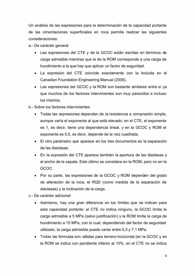
Un análisis de las expresiones para la determinación de la capacidad portante
de las cimentaciones superficiales en roca permite realizar las siguientes
consideraciones:
a.- De carácter general
Las expresiones del CTE y de la GCOC están escritas en términos de
carga admisible mientras que la de la ROM corresponde a una carga de
hundimiento a la que hay que aplicar un factor de seguridad.
La expresión del CTE coincide exactamente con la incluida en el
Canadian Foundation Engineering Manual (2006).
Las expresiones del GCOC y la ROM son bastante similares entre sí ya
que muchos de los factores intervinientes son muy parecidos e incluso
los mismos.
b.- Sobre los factores intervinientes
Todas las expresiones dependen de la resistencia a compresión simple,
aunque varía el exponente al que está elevado: en el CTE, el exponente
es 1, es decir, tiene una dependencia lineal, y en la GCOC y ROM el
exponente es 0,5, es decir, depende de la raíz cuadrada.
El otro parámetro que aparece en los tres documentos es la separación
de las diaclasas.
En la expresión del CTE aparece también la apertura de las diaclasas y
el ancho de la zapata. Este último se considera en la ROM, pero no en la
GCOC.
Por su parte, las expresiones de la GCOC y ROM dependen del grado
de alteración de la roca, el RQD (como medida de la separación de
diaclasas) y la inclinación de la carga.
c.- De carácter adicional
Asimismo, hay una gran diferencia en los límites que se indican para
esta capacidad portante: el CTE no indica ninguno, la GCOC limita la
carga admisible a 5 MPa (salvo justificación) y la ROM limita la carga de
hundimiento a 15 MPa, con lo cual, dependiendo del factor de seguridad
utilizado, la carga admisible puede variar entre 5,3 y 7,1 MPa.
Todas las fórmulas son válidas para terreno horizontal (en la GCOC y en
la ROM se indica con pendiente inferior al 10%, en el CTE no se indica

7/23/2019 Jornada Tecnica Semr 2015
http://slidepdf.com/reader/full/jornada-tecnica-semr-2015 15/77
7
ninguna pendiente) y para una inclinación de la resultante de carga
inferior al 10%. La GCOC y la ROM dan factores de corrección para
inclinaciones mayores. El CTE no los incluye, probablemente debido a
que en edificación no suelen darse inclinaciones mayores.
La GCOC y la ROM limitan el área de la cimentación a 100 m2,
indicando que se deben hacer estudios especiales en caso de mayores
áreas.
El CTE indica que cuando la cimentación superficial se encuentra en
roca puede haber problemas debido a la estructura de la misma, a la
orientación de las juntas, a la anisotropía del macizo, etc. e indica que en
esos casos se debe realizar un análisis específico.
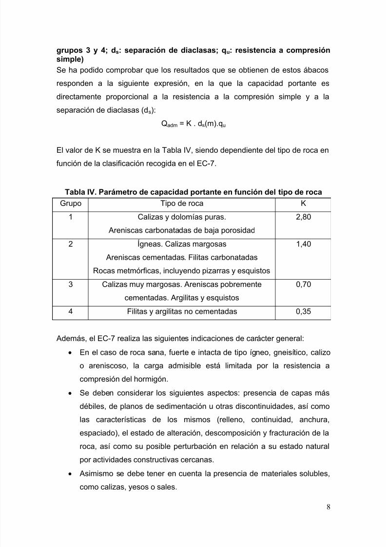
Por su parte, el EC-7 clasifica las rocas en cuatro grupos y proporciona un
ábaco, para cada grupo, con el que se puede estimar la carga admisible de las
cimentaciones superficiales en roca en función de la resistencia a compresión
simple de la matriz, la separación de diaclasas y del asiento permitido, (véase a
modo de ejemplo el ábaco de la Figura 1).
Figura 1. Ejemplo de ábacos recogidos en el EC-7 para la obtención de lacarga admisible de una cimentación superficial en roca (rocas de los
7/23/2019 Jornada Tecnica Semr 2015
http://slidepdf.com/reader/full/jornada-tecnica-semr-2015 16/77
8
grupos 3 y 4; ds: separación de diaclasas; qu: resistencia a compresiónsimple)
Se ha podido comprobar que los resultados que se obtienen de estos ábacos
responden a la siguiente expresión, en la que la capacidad portante es
directamente proporcional a la resistencia a la compresión simple y a laseparación de diaclasas (ds):
Qadm = K . ds(m).qu
El valor de K se muestra en la Tabla IV, siendo dependiente del tipo de roca en
función de la clasificación recogida en el EC-7.
Tabla IV. Parámetro de capacidad portante en función del tipo de rocaGrupo Tipo de roca K
1 Calizas y dolomías puras.
Areniscas carbonatadas de baja porosidad
2,80
2 Ígneas. Calizas margosas
Areniscas cementadas. Filitas carbonatadas
Rocas metmórficas, incluyendo pizarras y esquistos
1,40
3 Calizas muy margosas. Areniscas pobrementecementadas. Argilitas y esquistos
0,70
4 Filitas y argilitas no cementadas 0,35
Además, el EC-7 realiza las siguientes indicaciones de carácter general:
En el caso de roca sana, fuerte e intacta de tipo ígneo, gneisítico, calizo
o areniscoso, la carga admisible está limitada por la resistencia a
compresión del hormigón.
Se deben considerar los siguientes aspectos: presencia de capas más
débiles, de planos de sedimentación u otras discontinuidades, así como
las características de los mismos (relleno, continuidad, anchura,
espaciado), el estado de alteración, descomposición y fracturación de la
roca, así como su posible perturbación en relación a su estado natural
por actividades constructivas cercanas.
Asimismo se debe tener en cuenta la presencia de materiales solubles,
como calizas, yesos o sales.

7/23/2019 Jornada Tecnica Semr 2015
http://slidepdf.com/reader/full/jornada-tecnica-semr-2015 17/77
9
2.3. Capacidad portante de las cimentaciones profundas en roca
En la Tablas III se indican las expresiones utilizadas para la determinación de
la capacidad portante de las cimentaciones profundas en roca y se resumen los
principales aspectos contemplados en los tres documentos normativos.
Un análisis de las expresiones para la determinación de la capacidad portante
de las cimentaciones profundas en roca permite realizar las siguientes
consideraciones:
Las expresiones de la GCOC y de la ROM están escritas en términos de
carga de hundimiento, a la que hay que aplicar un factor de seguridad,
mientras que la del CTE corresponde a una carga admisible.
Los tres documentos determinan la carga admisible o última por punta
basándose en la carga admisible (GCOC y CTE) o última (ROM) de una
cimentación superficial, por lo que son válidas las diferencias ya
señaladas anteriormente, afectando dicha carga por un factor de
empotramiento.
Los tres documentos consideran unos factores de empotramiento
similares.
Tanto la GCOC como la ROM determinan la carga última por fuste como
un porcentaje (10%) de la carga última por punta, limitando dicho valor a
2 MPa.
La expresión del CTE coincide básicamente con la incluida en el
Canadian Foundation Engineering Manual (2006).
Por su parte, el EC-7 no menciona ninguna fórmula de cálculo analítica, ya
que en las cimentaciones profundas se da prioridad al diseño basado en
ensayos estáticos de carga.

7/23/2019 Jornada Tecnica Semr 2015
http://slidepdf.com/reader/full/jornada-tecnica-semr-2015 18/77
1 0
T a b l a I I I . C a r g a d e h u n d i m
i e n t o d e u n a c i m e n t a c i ó n p r o f u n d a e n r o c a .
R e s u m e n d e p r i n c i p a l e s a s p e c t o s c o n t e m p l a d o s e n
l o s t r e s d o c u m e n t o s n o r m
a t i v o s
D o c u m e n t o
C a p a c i d a d p o r t a n t e d e u n p i l o t e e n r o c a , q a , p
D e p
e n d e d e
G C O C
= 2
< 2 0
M P a
= 1 +
0 , 4
≤ 2
= 0
, 1
< 2 M
P a s i W D ≤ I I I ; d f = 1 e n q p
= 0 s i W D > I I
I
F S = 3 ( p e r m a n e n t e ) ; 2 , 6
( c a r a c t e r í s t i c a ) ; 2 , 2
( a c c i d e n t a l )
- q p :
r e s i s t e n c i a u n i t a r i a p o r p u n t a ( d e h u n d i m i e n t o ) .
- f : r e s i s t e n c i a u n i t a r i a p o r f u s t e ( d e h u n d i m i e n t o ) .
q a : c a r g a a d m i s i b l e d e u n a c i m e n t a c i ó n s u p e r f i c i a l ( v e r T a b l a I I ) .
- L r :
l o n g i t u d d e e m p o t r a m i e n t o e n r o c a d e i g u a l o m
e j o r c a l i d a d q u e l a d e l a
p u n
t a .
- D : d i á m e t r o d e l p i l o t e .
R O M
= 2 3
= 1 +
0 , 4
= 0
, 1
< 2 M P a s i W D ≤ I I I
= 0 s i W D > I I
I
F S = 2 , 5
( p e r m a n e n t e ) ; 2 , 2
( f u n d a m e n t a l ) ; 2 , 0
( a c c i d e n t a l )
- q p :
r e s i s t e n c i a u n i t a r i a p o r p u n t a ( d e h u n d i m i e n t o ) .
- f : r e s i s t e n c i a u n i t a r i a p o r f u s t e ( d e h u n d i m i e n t o ) .
- q u l t : c a r g a d e h u n d i m i e n t o d e u n a c i m e n t a c i ó n s u p e r f i c i a l ( v e r T a b l a I I ) .
- L r :
l o n g i t u d d e e m p o t r a m i e n t o e n r o c a d e i g u a l o m
e j o r c a l i d a d q u e l a d e l a
p u n
t a ( L r
≤ 2 , 5 D ) .
- D : d i á m e t r o d e l p i l o t e .
C T E
,
=
=
.
.
= 1 +
0 , 4
≤
3
= 0
, 2 .
, 5
- q p , d : c a r g a a d m i s i b l e p o r p u n t a , s i e n d o q a
l a c a r g a a d m i s i b l e d e u n a c i m e n t a c i ó n
s u p e r f i c i a l s e g ú n e l C T E , d e f i n i d a e n l a T a b l a I I .
- f , d : c a r g a a d m i s i b l e p o r f u s t e , e n M P a .
- U C
S : r e s i s t e n c i a a c o m p r e s i ó n s i m p l e , e n M P a .
- L r :
l o n g i t u d d e e m p o t r a m i e n t o e n r o c a d e i g u a l o m
e j o r c a l i d a d q u e l a d e l a
p u n
t a .
- D : d i á m e t r o d e l p i l o t e .

7/23/2019 Jornada Tecnica Semr 2015
http://slidepdf.com/reader/full/jornada-tecnica-semr-2015 19/77
11
3. IDEAS PARA UNA POSIBLE UNIFICACIÓN DE LAS EXPRESIONESRECOGIDAS EN LAS NORMATIVAS ESPAÑOLAS
La primera cuestión que se debe suscitar es de carácter formal ya que
convendría unificar las expresiones para que todas ellas estuvieran en términos
de carga de hundimiento de tal manera que el cálculo de las cimentaciones en
roca se pareciera lo más posible a las cimentaciones en suelos.
Otra cuestión que se plantea es la de la necesidad o no de limitar el valor
máximo de la carga admisible, como se hace en la GCOC y en la ROM. A este
respecto, se considera que no parece necesario poner tales límites, ya que
existen otras limitaciones debidas a la resistencia de los propios materiales
constructivos (el punzonamiento de las cimentaciones superficiales y el “tope
estructural” de los pilotes) y puede resultar quizá excesivamente conservador
cuando se ha hecho un estudio adecuado del terreno y se dispone de un
macizo rocoso de buena calidad.
En cuanto a la forma de estimar la carga admisible, parece que su estimación
en función de la raíz cuadrada del valor de la resistencia a compresión simple
es menos común en la práctica habitual, aunque es menos conservadora en el
rango de resistencias bajas, pero más conservadora en el de presioneselevadas, por lo que podría ser la más adecuada, eliminando los límites de
valor máximo. Soriano (2003) comenta las razones que llevaron a las
expresiones recogidas en la GCOC y la ROM.
A este respecto es muy interesante la recopilación realizada por Serrano et al
(2010) de diferentes teorías y normativas, recogida en la Figura 2, en la que se
puede apreciar que el exponente que se preconiza tiende a ser 1, aunque
también hay casos de 0,5. Serrano et al. proponen valores intermedios,cercanos a 0,75.

7/23/2019 Jornada Tecnica Semr 2015
http://slidepdf.com/reader/full/jornada-tecnica-semr-2015 20/77
12
Figura 2. Resumen de teorías y normativas sobre carga de hundimientoen punta de pilotes
Asimismo, es necesario y conveniente señalar la primordial importancia que
puede tener la estructura del macizo en relación a las cargas aplicadas, ya que
se pueden producir mecanismos de rotura que requieran un estudio específico,
como señala el CTE y como se indica, a modo de ejemplo, en la Figura 3Figura
3, tomada de Lamas et al (2014).

7/23/2019 Jornada Tecnica Semr 2015
http://slidepdf.com/reader/full/jornada-tecnica-semr-2015 21/77
13
Figura 3. Fallo de una cimentación por un mecanismo de rotura producidopor la existencia de una falla y un sistema de diaclasas (Lamas et al, 2014)
Serrano y Olalla (1998) han estudiado en profundidad la posible formación de
mecanismos de rotura en macizos diaclasados en función de la orientación y
resistencia de las diaclasas (Figura 4).
Figura 4. Posibles mecanismos de rotura en función del buzamiento delas diaclasas (Serrano y Olalla, 1998)

7/23/2019 Jornada Tecnica Semr 2015
http://slidepdf.com/reader/full/jornada-tecnica-semr-2015 22/77
14
Se considera que puede ser conveniente hacer referencia a los resultados de
este estudio, especialmente en lo que se refiere a la disminución de la carga de
hundimiento por efecto de la existencia de planos de discontinuidad con menor
resistencia que la propia roca matriz, como puede verse en la figura siguiente.
Figura 5. Reducción de la carga de hundimiento por efecto de existenciade planos de debilidad (Serrano y Olalla, 1998)
Como puede verse en este gráfico, hay situaciones en las que la reducción de
la carga de hundimiento llega a ser del 90%.
4. BIBLIOGRAFÍA
Canadian Foundation Engineering Manual. 2006. 4th Edition. Canadial
Geotechnical Society.
Código Técnico de la Edificación. 2003. Documento Básico DB-4Cimentaciones. Ministerio de Fomento.
Estaire, J., Pardo, F. & Perucho, A. 2014. Bases del Anejo Nacional Españoldel Eurocódigo EC-7 (Proyecto Geotécnico). Hormigón y Acero 271 (2014, trim.1).
Guía de Cimentaciones de Obras de Carreteras. 2003. Ministerio de Fomento.
Harrison, J. 2014. Eurocode 7 and rock engineering: current problems andfuture opportunities. Congreso europeo Eurock 2014. Vigo.

7/23/2019 Jornada Tecnica Semr 2015
http://slidepdf.com/reader/full/jornada-tecnica-semr-2015 23/77
15
Lamas, L., Perucho, A. y Alejano, L. 2014. Some key issues regardingapplication of Eurocode-7 to rock engineering design. Congreso europeoEurock 2014. Vigo.
Orr, T. 2012. How Eurocode 7 has affected geotechnical design: a review.Geotechnical Engineering, Vol. 165, Issue GE6.
Perucho, A. y Estaire, J. The approach to rock engineering in Spanishnormative documents. Congreso europeo Eurock 2014. Vigo, mayo 2014.
Recomendaciones Geotécnicas para el Proyecto de Obras Marítimas yPortuarias”, ROM 0.5-05. 2005. Ministerio de Fomento, Puertos del Estado.
Serrano, A. & Olalla C. 1998. Ultimate bearing capacity on an anisotropicdiscontinous rock mass. Part I: Basic modes of failure. Int. J. Rock Mech. Min
Sci. 35 : 301–324.
Serrano, A. & Olalla C. 2002. Carga de hundimiento por punta de pilotes enrocas. Monografía CEDEX.
Serrano González, A., Olalla Marañón C. y Juárez Millán, F. 2010. Cargas dehundimiento por punta para pilotes en roca: estudio comparativo. IngenieríaCivil 160.
Soriano, A. 2003. Point resistance of piles in rock. MS 4-Co-report. EuropeanConference on Soil Mechanics and Geotechnical Engineering; geotechnicalproblems with man-made and man influenced grounds. Vol. 3. Praga.
Workshop Eurock 2014. Applicability and application of Eurocode-7 to rockEngineering design. 26th May, Vigo, Spain. Chairman: J. Harrison.

7/23/2019 Jornada Tecnica Semr 2015
http://slidepdf.com/reader/full/jornada-tecnica-semr-2015 24/77

7/23/2019 Jornada Tecnica Semr 2015
http://slidepdf.com/reader/full/jornada-tecnica-semr-2015 25/77
El artículo que se recoge a continuación se presentó al congreso Eurock 2014 celebrado en
Vigo en Mayo de 2014

7/23/2019 Jornada Tecnica Semr 2015
http://slidepdf.com/reader/full/jornada-tecnica-semr-2015 26/77

7/23/2019 Jornada Tecnica Semr 2015
http://slidepdf.com/reader/full/jornada-tecnica-semr-2015 27/77
1 INTRODUCTION
Eurocode 7 (EC-7) is the European referencedocument to design the geotechnica aspects of
!uiding and ci"i engineering pro#ects$ EC-7% named&'eotechnica design% has to parts* +art 1&'enera rues as appro"ed !, NormaiationEuropean Committee (CEN) in .pri /00 and +art/ &'round in"estigation and testing as appro"edin 2anuar, /007$
This document deas ith amost a thegeotechnica or3s* spread and pie foundations%anchorages% retaining structures% em!an3ments%o"era sta!iit, and h,drauic faiures ithout an,distinction !eteen soi and roc3s% athough theaspects reated to sois are 4uite more ree"ant$ Thisis the reason h, the 5u!committee 5C-7 of CEN-TC /60% responsi!e of riting EC-7% created aor3ing group de"oted to emphasie the roe ofRoc3 echanics inside EC-7$
The aim of this paper is to hep that committee inits tas3 as it ma3es a proposa to perform the
cacuation of spread foundations on roc3s and thesta!iit, ana,sis of roc3 sopes in the EC-7frameor3$
/ 5+RE.D 8OUND.TION5 ON ROC95
/$1 Spread foundations in EC-7
.ccording to EC-7 frameor3% the cacuation of
an, utimate imit state !asica, in"o"es the"erification of the fooing e:pression*
Ed ; R d (1)
here Ed is the design "aue of the effect of actionsand R d is the design "aue of the ground resistancethat depends on the utimate imit state considered$The design "aue of effect of actions (Ed) iscacuated from the characteristic "aues of effects ofactions% affected !, the partia factor on effect ofactions (γ E) hose "aues% proposed !, EC-7% areshon in the fooing ta!e$
Ta!e 1$<aues of partia factor on the effect of actions ( γ E) as proposed in EC-7
T,pe of actions or effect of actions <aue
Unfa"oura!e 1%=6+ermanente
8a"oura!e 1%00
Unfa"oura!e 1%60Transient
8a"oura!e 0
Ta3ing into account these "aues and the fact thatin a norma structure the permanent actions areusua, a!out />= of the tota% an a"erage "aue of γ E coud !e around 1%0$ This "aue i !e used ater
The design "aue of the ground resistance (R d) iscacuated from the characteristic "aue of theground resistance affected !, the partia resistancefactor (γ R )$
Design "aues of soi properties in"o"ed in thecacuation of the utimate imit state are o!tainedfrom their characteristic "aues affected !, the
partia factor for soi parameters (γ )$ It is importantto remem!er that EC-7 points out that 'thecharacteristic value of a geotechnical parameter
shall be selected as a cautious estimate of the value
affecting the occurrence of the limit state' $ ?Cause/$$6$/$(/)@$
5pread foundations and sope sta!iit, cacuations on roc3s according toEurocode EC-7
2$ Estaire A '$ Oi"ena Laboratorio de Geotecnia (CEDEX! "adrid! Espa#a!
Corresponding author$ %ose!estaire&cede!es
.B5TR.CT* This paper proposed a method to impement the EC-7 frameor3 in the cacuation of shaofoundations on roc3 and roc3 sope sta!iit, pro!ems$ +re"ious, a re"ision of the usua methods current,used is made$

7/23/2019 Jornada Tecnica Semr 2015
http://slidepdf.com/reader/full/jornada-tecnica-semr-2015 28/77
/$/ Spread foundations on rocs according to EC-7
Cause $7 of EC-7 is de"oted to gi"e somerecommendations on spread foundation on roc3s$This section is 4uite "ague as it on, indicates thatcacuations must consider some aspects such as thestrength and deforma!iit, of the roc3 mass%
presence of ea3 a,ers% characteristics of
discontinuities% eathering% decomposition andfracturing degree of the roc3 and the ateration of thenatura state of the roc3 caused !, constructionacti"ities$8urthermore% EC-7 specifies that 'spread foundationon roc ma) normall) be designed using the methodof presumed bearing pressures!' (Cause $7$(/)) andrecommends the method incuded in .nne: ' '*
sample method for deriving presumed bearingresistance for spread foundation on rocs' $ This.nne: contains four graphs for different t,pes ofroc3% hose resuts depend on the unia:ia
compressi"e strength (4u in the graph) and thediscontinuit, spacing (ds)$ The fooing figureshos one of those graphs$
8igure 1$ +resumed !earing resistance for s4uare padfoundations !earing on roc3 (for settements not e:ceeding 0%6 of foundation idth)$ (This graph is for roc3s of 'roup =formed !, "er, mar, imestones% poor, cemented sandstones%sates and schists steep cea"age>foation)$
It shoud !e noted that this a, of cacuating partia, contradicts the EC-7 cacuation phiosoph,
!ased on the appication of partia factors (onactions% to resistances and to soi properties) insteadof using a go!a securit, factor hich it is inherentto the concept of presumed !earing resistance$
/$= "ethods of calculation of the ultimate bearingresistance of spread foundations on rocs
The usua methods to cacuate the utimate !earing resistance of spread foundations on roc3(4ut) most, depends direct, on the unia:iacompressi"e strength (σc) of the roc3 matri: and% inan indirect a,% on the characteristics of the roc3
mass% through the Nσ parameter% as it can !e seen inthe fooing e:pression*
cult + , σ σ $= (/)
There are man, authors in iterature that ha"egi"en "aues for Nσ$ Couetdic A Barron (176)summaried the different faiure criteria used !,other se"era authors$ 8igure / shos the "ariation of
Nσ ith the friction ange% used as !asic parameter inamost a the theories$
8igure /$ <ariation of Nσ ith the friction ange (Ta3en fromCouetdic A Barron % 176)
It can !e seen that for "aues of friction ange inthe range !eteen =0 and 0F% Nσ ta3es "aues
!eteen = and 16$Once the utimate !earing resistance (4ut) is
o!tained% the ne:t step is to determine an aoa!e
!earing resistance (4a) di"iding the utimate !earingresistance !, a go!a safet, factor (8)$
This same t,pe of e:pressions can aso !e foundin codes i3e% for instance% in the Canadian8oundation Engineering anua (/007)$ In this case%the parameter Nσ has !een su!stituted !, an empiricfactor 9 sp that depends on the foundation idth (B)and the spacing (c) and aperture (δ) of thediscontinuities$
cc spcac
c . + , σ
δ σ σ σ $
>=00110
>=$$
+
+=== (=)
.s this e:pression is on, "aid for 0%06 ; c>B ;/%0 and 0 ; δ>c ; 0%0/% the factor 9 sp can ta3e "auesfrom 0%1 to 0%6 as it can !e seen in 8igure =$ Thefactor 9 sp incudes a go!a securit, factor e4ua to=$

7/23/2019 Jornada Tecnica Semr 2015
http://slidepdf.com/reader/full/jornada-tecnica-semr-2015 29/77
8igure =$ <aues of 9 sp factor
.nother e:pression that depends direct, on σc isthe one pro"ided !, D$C$ G,ie (1/)% athough inthis case the parameter Nσ is !ased on the Hoe3-Bron faiure criterion% through its parameters mand s it aso depends on a correction factor Cf1 thatconsiders the foundation shape$ This factor Cf1 ta3es"aues from 1 to 1%/6$
) c fl cult sms sC + , σ σ σ $)($$ 6%06%06%0 ++== ()
The aoa!e !earing pressure (4a) is the resutof affecting the utimate !earing capacit, (4ut) !, ago!a safet, factor that i !e% for most oadingconditions and according to this author% in the rangeof / to =$
This same e:pression is aso used !, the..5HTO manua (/007) that pro"ides a ta!e ith"aues for m and s depending on the t,pe and 4uait,of the roc3$ Ta3ing into account those "aues% Nσ
"aries from 0%00/ to 7$There is another group of e:pressions in hich σc
appears ith an e:ponent different to 1% athoughusua, e4ua to 0%6% i3e in the 5panish Codes forroad ('uJa de Cimentaciones de O!ras de Carretera)or ports or3s (RO 0$6-06)$ In these codes% theutimate !earing resistance depends on the s4uareroot of the unconfined compressi"e strength and onsome factors that ta3e into account the t,pe of theroc3% the presence of discontinuities% the eatheringdegree of the roc3 and the incination of the oad
(+erucho A Estaire% /01)$ 8or instance% thee:pression used in RO 0$6-06 is the fooing one*
$$$$$$= δ
σ f f f
p p, * D
r
cr ult = (6)
here pr is a reference pressure to gi"e units tothe e:pression% usua, e4ui"aent to 1 +a$
The factor f D ta3es into account the presence ofdiscontinuities$ It i !e the minimum "aue of theto fooing e:pressions% here s is the distance
!eteen discontinuities% B0 is a reference idthe4ua to 1 m and BK is the e4ui"aent foundationidth*
1$$/%01$$/K
()0
K <=≤=
/0D f
s f D D ()
The factor f . is a reduction factor due to theeathering degree% hose "aues are 1%0 0%7 or 0%6for eathering degrees I% II or III% respecti"e,% and f δ is the factor that considers the oad incination%according to the e:pression*
1)1%1(= <−= δ δ tg f
(7)The cacuation of the aoa!e !earing
resistance is made di"iding the utimate !earing
resistance !, the corresponding securit, factor%hose recommended "aue in this standard for thecharacteristic situation is /%=$
/$ 1roposal of a method to design foundations onrocs compatible 2ith EC-7 frame2or
The "erification of the utimate imit state of !earingresistance of a spread foundation sha !e made
!ased on E:pression (1)$ ?Ed;R d@$ .s said in 5ection=$1% the design "aue of the effect of actions (Ed) andthe design "aue of the ground resistance (R d) can !ecacuated from their respecti"e characteristic "auesaffected !, their partia factors% as shon in thefooing e:pressions (L)$
EdMEc3 $ γ E (L)Ed;R d M
R dMR c3%(3>γ ) > γ R R dM4ut%(3>γ ) > γ R
One of the main points of this proposa is that thecharacteristic "aue of the ground resistance (R c3 )can !e considered as the "aue of the utimate
!earing resistance (4ut) that can !e deri"ed from an,of the e:pressions indicated in pre"ious section$ Too!tain this utimate !earing resistance% the design"aues of the parameters (d) must !e used% hichare o!tained di"iding their characteristics "aues(3 ) !, the partia materia factor (γ )$
Once esta!ished the main e:pressions% the ne:tstep is to esta!ish the "aues for the different partiafactors (γ E% γ R % γ )$ To do so% it must !e noted thatEC-7 aos ma3ing the cacuations according
!asica, to to Design .pproaches (D.)* D.-/hich is a Resistance 8actor .pproach (R8.) andD.-1 and D.-=% hich are ateria 8actor.pproaches (8.)$ 8or !oth approaches% the partiafactor of effect of actions (γ E) sha !e ta3en fromTa!e 1$

7/23/2019 Jornada Tecnica Semr 2015
http://slidepdf.com/reader/full/jornada-tecnica-semr-2015 30/77
a) Resistance 8actor .pproach (as D.-/)In this approach% the partia materia factor (γ ) is 1%so the parameter "aues to !e used in the e:pressionsto determine the utimate !earing resistance(coected in 5ection /$=) are the characteristic ones$On the other hand% the determination of the "aue ofthe partia resistance factor can !e done using thefooing e:pressions% as can !e seen in 8ran3% R$
(/007)% !ased on the o!#ecti"e to get simiarfoundation dimensions hen comparing the usuamethod and the one proposed in the EC-7frameor3$
Ta!e /$ ethod to determine the "aue of the partia factor forresistances (γ R )
Usua method +roposa EC-7 method
3
+ , c
a
σ σ $=
aact ,, =
3 + , c
act σ σ $=
d d / E =
/
c E act
+ ,
γ
σ γ σ $$ =
/ E
cact + ,
γ γ σ σ
$$=
/ E 3 γ γ $=
$ E
/ 3
γ γ =
here 4a is the aoa!e !earing resistance% 4act isthe actua acting oad on the foundation and 8 is thego!a safet, factor recommended in the cacuationmethod used$8or instance% if the method esta!ished in theCanadian Code is used% the recommended "aue for8 is =% so considering an a"erage "aue of 1% for γ E%as said in 5ection /$1% the partia factor γ R shoudta3e a "aue of /%16$
This "aue of the partia resistance factor (γ R )shoud !e found in the Nationa .nne:es of thedifferent countries$ Hoe"er% it must !e noted thatthe "aues that appears noada,s in those Nationa.nne:es are usua, referred to spread foundationson sois% so the, ma, need to !e changed$
!) ateria 8actor .pproach (as D.-= and D.-1)In this approach% the partia resistance factor (γ R )ta3es a "aue of 1 so the design "aue of groundresistance is the characteristic one$
Hoe"er% the parameter "aues to !e used in thee:pressions to determine the ground resistance must
!e affected !, their corresponding materia factor$ Inthis case% the parameters that appear in thosee:pressions (as seen in 5ection /$=) are theunconfined compressi"e strength (σc) and someothers that descri!e the t,pe of roc3 and the roc3mass state (as for instance* m% s% RR or the spacingand aperture of the discontinuities)$
Using the same a, of thin3ing as !efore% thedetermination of the "aues of the partia materia
factors can !e done ta3ing into account the fooinge:pressions*Ta!e =$ ethod to determine the "aue of the partia factor formaterias (γ )
Usua method +roposa EC-7 method
3
+ , c
a
σ σ $=
aact ,, =
3
+ , c
act
σ σ $=
d d / E =
c " + "
c E act
+ ,
σ σ
σ
γ γ
σ γ
%%
$
$$ =
)()( $$
$
c " + " E
cact
+ ,
σ
σ
γ γ γ
σ
σ /
=
)()( $$c " + " E 3 σ γ γ γ
σ /=
E " + "
3 c γ
γ γ σ σ =
/ )()( $
.ccording to the ast e:pression% the simpest proposa is to consider the partia materia factor forthe Nσ parameter must ta3e a "aue of 1% as it
descri!es the roc3 mass state hose reduction is4uite difficut to 4uantif,$ 8or σc% the partia factorshoud !e e4ua to 8>γ E$ .gain% for instance% if themethod esta!ished in the Canadian Code is used%γ (σc) shoud ta3e a "aue of /%16$
Once arri"ed at this point% there are to aspectsthat must !e carified$ The first one is that EC-7% inits .nne: .% proposes a "aue of the partia factorfor the unconfined compressi"e strength (σc) e4uato 1%% hose "aue can !e modified in the Nationa.nne:es$ .s noticed% this "aue (1%) is 4uite smaerthan the one cacuated pre"ious, (/%16)$ To so"e
this gap% it can !e said that the "aue proposed !,EC-7 on, appies for sois% so the Nationa .nne:esha"e to define its "aue for roc3s$
The second aspect is that the e:pression o!tained !efore on, guarantees the same foundationdimensioning if the e:ponent of σc is 1$ If thee:ponent is 0%6% as usua% the ma:imum acting oadis going to !e around 60 higher ith the EC-7dimensioning compared ith the one ith the usuamethods$ One a, to so"e this pro!em coud !e toreate the "aue of the partia materia factor ith a
specific e:pression to cacuate the !earingresistance% something that can !e done in the Nationa .nne:es$
/$6 Settlement calculations! Serviceabilit) limit state design
The "erification of ser"icea!iit, imit state isanother necessar, step in the design of foundationsaccording to EC-7 frameor3$ This is a compicatedtas3 since EC-7 does not gi"e an, indication of hoto tac3e the cacuation$ Hoe"er% in spreadfoundations on roc3s% the settement imit is notusua, an important issue as the roc3 mass canusua, !e considered as a stiff ground in hichsettements are negigi!e$

7/23/2019 Jornada Tecnica Semr 2015
http://slidepdf.com/reader/full/jornada-tecnica-semr-2015 31/77
= ROC9 5PO+E 5T.BIPITQ
This chapter discusses the cacuation of roc3 sopesta!iit, according to EC-7 in reation to the usuamethod of cacuation$ 8aiure in roc3 sope ismain, rued !, discontinuities hich can pro"idethe mo"ement of discrete !oc3s$ To modes offaiure are ana,ed* pane siding and edge faiure$
=$1 *nal)sis of plane slides
The geometr, of the genera case considered in theana,sis of pane sides faiure is shon in thefooing figure$
8igure $ 'eometr, for genera ana,sis of pane faiure (.fterHoe3 and Bra,% 1L1)
If the side mass !eha"es i3e a rigid !od,% thesecurit, factor can !e e:pressed ith the fooinge4uation*
δ δ
φ δ δ
cossin
tan)sincos(
⋅+⋅
⋅−−⋅+⋅=
4 5
4 6 5 *c 3 ()
here c and φ are the cohesion and friction angein the siding surface% δ is the dip of the sidingsurface% . is the ength (area per unit idth) of thesiding surface% U is the resutant of the ater
pressure aong the siding surface and < is theresutant of the ater pressure aong the tensioncrac3$
=$/ 5edge failure
8igure 6 shos the geometr, of the edge hich
i !e considered in the fooing ana,sis$ It isassumed that siding of the edge aa,s ta3es paceaong the ine of intersection of panes . and B$
The factor of safet, for the edge defined !,these panes . and B% assuming that siding isresisted !, friction on, and that the friction ange φ is the same for !oth panes% is gi"en !,*
i
*
5
/ / 3
ψ
φ
sin
tan)(
⋅
+= (10)
here R . and R B are the norma reactions pro"ided !, panes . and B as iustrated in 8igure and ψ is the ange of the ine of intersection and thehorionta pane$
E4uations for edges resisted !, !oth friction andcohesion are not incuded !ecause the, are 4uitemore compicated !ut simiar from a conceptua
point of "ie$
8igure 6$ 'eometr, of edge used for sta!iit, ana,sisincuding the infuence of cohesion and of ater pressure onthe faiure surfaces (.fter Hoe3 and Bra,% 1L1)
8igure $ Reactions pro"ided !, panes . and B (.fter Hoe3and Bra,% 1L1)
=$= 1roposal of a method to anal)e roc slope stabilit) problems compatible 2ith EC-7
To tac3e this pro!em% D.-1 and D.-= aree4ui"aent and D.-/ has not !een chosen !, an,European countr, as the on, D. to use in this case(Estaire% 2$ et a% /01=)% so this section is on,focused on D.-=$
In this approach% the partia resistance factor (γ R )
ta3es a "aue of 1$ 8or this pro!em and according toCause /$$7$=$$ - Note / of EC-7% &the actions onthe soil (structural or traffic load are treated as
geotechnical actions and sha !e factored !, the partia factors for actions shon in Ta!e $

7/23/2019 Jornada Tecnica Semr 2015
http://slidepdf.com/reader/full/jornada-tecnica-semr-2015 32/77
Ta!e $<aues of partia factor on the effect of actions ( γ E) as
proposed in EC-7 for sta!iit, pro!ems
T,pe of actions or effect of actions <aue
Unfa"oura!e 1%00+ermanente
8a"oura!e 1%00
Unfa"oura!e 1%=0Transient
8a"oura!e 0
These "aues mean that permanent actions% !othfa"oura!e and unfa"oura!e% due to roc3 or atereight are affected !, a partia factor e4ua to 1$
The determination of the "aues of the partiamateria factors can !e done ta3ing into account thefooing e:pressions% !ased again on E:pression(1)$ ?Ed;Rd@$
Ta!e 6$ ethod to determine the "aue of the partia factor formaterias (γ ) in case of pane sides
Usua method +roposa EC-7 method
δ δ
φ δ δ
cossin
tan)sincos(
⋅+⋅
⋅−−⋅+⋅=
4 5
4 6 5 *c 3
δ δ
φ δ δ
cossin
>)tan)sincos((1
⋅+⋅
⋅−−⋅+⋅=
4 5
3 4 6 5 *c
d d / E = d
d
E /
=1
( ) E d 4 5 E γ δ δ ⋅⋅+⋅= cossin
" "
4 6 5 *c
/d γ
φ δ δ
γ tan)sincos( ⋅−−⋅+=
E
" "
4 5
4 6 5 *c
γ δ δ
γ
φ δ δ
γ
)cossin(
tan)sincos(
1⋅+⋅
⋅−−⋅+
=
γ EM1 for fa"oura!e actions and for unfa"oura!e permanentactions γ EM1%= for unfa"oura!e transient actions
" 3 γ =
Ta!e $ ethod to determine the "aue of the partia factor formaterias (γ ) in case of edges
Usua method +roposa EC-7 method
i
*
5
/ / 3
ψ
φ
sin
tan)(
⋅
⋅+=
i
*
5
3 / /
ψ
φ
sin
>)tan)((1
⋅
⋅+=
d d / E = d
d
E /
=1
E id 5 E γ ψ ⋅⋅= sin
"
* / / /d
γ
φ tan)( ⋅+=
E i
"
*
5
/ /
γ ψ
γ
φ
⋅⋅
⋅+
=sin
tan)(
1
γ EM1 for fa"oura!e actions and for unfa"oura!e permanentactions γ EM1%= for unfa"oura!e transient actions
" 3 γ =
.s it is seen in the pre"ious ta!es% the "aue ofthe partia factor of materias shoud !e ta3en as the
"aue of the safet, factor used noada,s if a simiare"e of safet, ants to !e achie"ed$ The on, ittedifference is the factoring of the e:terna oads !,the "aue 1%=% hich it is not usua, used$
The "aue of the partia factor for the geotechnica parameters has to !e incuded in the Nationa .nne:of e"er, countr,$ 8or e:ampe% the "aues proposedin 5panish Nationa .nne: for the genera case aree4ua to 1% for persistent situations% 1%/6 fortransient situations and 1%10 in accidenta ones% fore"er, geotechnica parameter (cohesion and frictionange) e:cept in densit, in hich the partia factor is
e4ua to 1%0 in a the situations mentioned$
CONCPU5ION5The methods proposed to design spread foundationson roc3s and to ana,e the sta!iit, of roc3 sopesaccording to EC-7 are deri"ed from the usuamethods used noada,s since*- In spread foundations% resistance partia factor (γ R )and the materia partia factor (γ ) are reated di-rect, ith the go!a safet, factor of the usua meth-ods$ The "aues of these partia factors i depend
on the "aue of the standard considered !, usuamethods$- In sope sta!iit,% using the Design .pproach =% asmost European countries do% the "aue of partiamateria factor is e4ua to the "aue of the go!asafet, factor considered in usua methods$
The "aues of the partia factors% o!tained usingthe method proposed% sha !e specified in the Na-tiona .nne: of each countr,% specifica, for thesecases on roc3s$
6 RE8ERENCE5
.55HTO (/007)$ L/3D ridge Design Specifications$.merican .ssociation of 5tate Higha, and TransportationOfficias$ Gashington D$C$
Canadian 8oundation Engineering anua (/007)$ Canadian'eotechnica 5ociet,% Toronto% Ontario$
Couetdic% 2$ $ A Barron 9$ (176)$ 1late-loading testing as amethod of assesng the in situ strength properties of 5esternCanadian coal! Int$ 2$ Roc3 ech$ in$ 5ci$ A 'eomech$.!str$ <o$ 1/% =0=-=10$
Duncan% C$ G,ie% (1/)$ 3oundations or roc! E A 8N
5+ON (.n imprint of Chapman A Ha)$Estaire% 2$% +ardo% 8$ A +erucho% .$ /01$ Bases de .ne#o Naciona Espao de EurocSdigo EC-7 (+ro,ecto'eotcnico)$ HormigSn , .cero (in print)$
8ran3% R$% 5chuppener% B$% <ogt% N$ A Geissen!ach% .$ (/007)$ Design approaches of Eurocode 7 for the verification ofultimate limit states in geotechnical design in 3rance andGerman)$ Re"ue Europenne de 'nie Ci"i% "o$ 11% nF 6%mai /007% p$ /1-1$
'uJa de Cimentaciones de O!ras de Carreteras$ /00=$inisterio de 8omento$
Hoe3% E$ A Bra,% 2$ (1L1) /oc Slope Engineering $ CRC+ress$
+erucho% .$ A Estaire% 2$ (/01)$ 8he approach to roc
engineering in Spanish normative! Euroc3 /01% <igo(5pain)
Recomendaciones 'eotcnicas para e +ro,ecto de O!rasarJtimas , +ortuarias% RO 0$6-06$ /006$ inisterio de8omento% +uertos de Estado$

7/23/2019 Jornada Tecnica Semr 2015
http://slidepdf.com/reader/full/jornada-tecnica-semr-2015 33/77

7/23/2019 Jornada Tecnica Semr 2015
http://slidepdf.com/reader/full/jornada-tecnica-semr-2015 34/77
SEMR
JORNADA TÉCNICA 2015EL EUROCÓDIGO 7 Y OTRAS NORMATIVAS
Los valores característicos de los parámetros
geotécnicos de las rocas
D. Alberto Bernal Riosalido
ByA Estudio de Ingeniería S.L.
Universidad Politécnica de Madrid

7/23/2019 Jornada Tecnica Semr 2015
http://slidepdf.com/reader/full/jornada-tecnica-semr-2015 35/77
1
LOS VALORES CARACTERÍSTICOS DE LOS PARÁMETROSGEOTÉCNICOS DE LAS ROCAS EN UNE-EN 1997
Alberto Bernal RiosalidoIngeniero de Caminos
ByA Estudio de Ingeniería S.L.
1. INTRODUCCIÓN
Son numerosos los Proyectos Geotécnicos donde intervienen macizos rocosos, comosoporte de cimentaciones, como terreno en el que se desarrollan excavaciones, comomaterial de construcción, etc.
Entre los diferentes métodos de proyecto que contempla UNE-EN 1997 se van aconsiderar en este trabajo los que están basados en cálculos, en los cuales esnecesario asignar a la roca unos valores de cálculo de los parámetros geotécnicos. Unconcepto clave en el proceso de asignación de valores de cálculo a los parámetrosgeotécnicos es de la obtención de los valores característicos de los mismos.Precisamente, una de las principales novedades que aporta UNE-EN 1997 es ladefinición precisa del valor característico y del valor de cálculo de los parámetros
geotécnicos, así como el establecimiento de los procedimientos con los que debencalcularse.
2. PARÁMETROS GEOTÉCNICOS DE LAS ROCAS
El comportamiento de las rocas en los proyectos de cimentaciones o taludes puedeclasificarse en varios tipos, en cada uno de los cuales los parámetros geotécnicos juegan un papel específico.
- Macizos rocosos diaclasados con rotura según las litoclasas, cuyo comportamientoestá controlado por la resistencia de estas. La mayoría de los proyectos de taludesen roca se regirían por este tipo de comportamiento.
- Macizos rocosos diaclasados sin dirección preferente de rotura, cuyocomportamiento está controlado principalmente por la imbricación de los diferentes
bloques de roca. En general, los proyectos de cimentaciones en roca se regirían poreste tipo de comportamiento.
- Rocas blandas masivas, cuyo comportamiento está controlado por las propiedadesde la matriz rocosa. En general, cualquier actuación sobre una roca blanda masivase regiría por este tipo de comportamiento.
En el primer tipo de comportamiento, los parámetros más influyentes son la geometríade las litoclasas y su resistencia.

7/23/2019 Jornada Tecnica Semr 2015
http://slidepdf.com/reader/full/jornada-tecnica-semr-2015 36/77
2
En los otros casos, los parámetros geotécnicos, de la matriz rocosa y, en su caso, delas litoclasas, controlan la seguridad y la funcionalidad de la obra.
Resulta necesario, por lo tanto, conocer los valores de los parámetros máspropiamente geotécnicos, pero también los parámetros geométricos de las litoclasas,
que pueden condicionar el comportamiento del macizo rocoso y que, en ese sentido,se pueden considerar como un parámetro geotécnico más. En la tabla 1 se presentauna relación de los parámetros geotécnicos más habituales de las rocas, así como losprocedimientos para su obtención.
Tabla 1. – Reconocimientos y ensayos habituales para la obtención deparámetros geotécnicos de las rocas
Parámetro adeterminar
Reconocimiento de Campo Ensayo de Laboratorio
Composición
mineralógica yquímica Estimación visual, lupa
Lámina delgada
Difracción de Rayos XEnsayos químicosResistencia acompresión de lamatriz
Estimación visual, martilloCompresión simpleTriaxialCarga puntual
Resistencia atracción de la matriz
- Brasileño
Módulo dedeformación de lamatriz
-Compresión simple o triaxial conbandas extensométricas
Geometría ycaracterísticas de
las juntas
Descripción geotécnica deafloramientos.
Testificación de sondeos
-
Resistencia de las juntas
Correlación con la rugosidad Corte directo de juntas
MeteorizaciónDescripción geotécnica deafloramientos.Testificación de sondeos
Lámina delgada
Densidad Densidad
Humedad Humedad
RQD Testificación de sondeos
Resistencia del
macizo
Correlación con los Índices de calidad geomecánica
Deformación delmacizo
Correlación con los Índices de calidad geomecánica
PermeabilidadEnsayos en sondeo o pozode bombeo

7/23/2019 Jornada Tecnica Semr 2015
http://slidepdf.com/reader/full/jornada-tecnica-semr-2015 37/77
3
3. VALOR CARACTERÍSTICO DE LOS PARÁMETROS GEOTÉCNICOS
3.1 Criterios generales
El proceso para la obtención del valor característico de los parámetros geotécnicos se
describe en la figura 1. Aunque Queda fuera del alcance de este trabajo, también seincluye en ella el proceso posterior para obtener el valor de cálculo.
Como en todo Proyecto Geotécnico la información de partida sobre las propiedades delas rocas consiste en:
- Valores medidos directamente en ensayos [de campo y de laboratorio], o deducidos
de los mismos, mediante interpretaciones basadas en las teorías geotécnicas o
mediante correlaciones empíricas.
- Información previa relevante, como .la información sobre la geología, la
geomorfología e hidrogeología de la zona o la procedente de reconocimientosgeotécnicos previos en la zona, o de información contrastada del comportamientode otras obras en el mismo tipo de terreno.
Reconocimientos y ensayosF = Campo; L= Laboratorio F1 F2 .....L1 L2 .....
Obtención directa (D)o Correlaciones (C)
Unidades geotécnicasParámetros medidos y deducidos
PM1 PD1 PM2 PD2...
C1 D2 C2
Modélo geotécnicoValores característicos de los parámetros
Valores de cálculo de los parámetros
Informaciónprevia
generaly local
Estimaciónprudente
Coeficientesparciales
D1
U N E -
E N 1
9 9 7 - 2
U N E -
E N 1
9 9 7 - 1
C A P Í T U L O 3
C A P Í T U L O S
4 a 6
Figura 1.- Esquema del proceso de obtención de los valores de cálculo de losparámetros geotécnicos según UNE-EN 1997
Los valores medidos y/o deducidos de los parámetros geotécnicos suelen estardistribuidos en un cierto rango alrededor de un valor medio, o (cuando haydependencia de otra variable, por ejemplo, la profundidad) de una línea de tendenciamedia. Con ese conjunto de valores debe ser definido el que denominamos valor
característico con las siguientes reglas incluidas en UNE-EN 1997-1, cláusula 2.4.5.2
(2)P:

7/23/2019 Jornada Tecnica Semr 2015
http://slidepdf.com/reader/full/jornada-tecnica-semr-2015 38/77
4
- El valor característico de un parámetro geotécnico ( X k) debe resultar unaestimación prudente del valor que controlará la ocurrencia del estado límite que se
desee comprobar . Debe estar basado en los valores medidos y en los deducidos de
los ensayos de campo y laboratorio, complementados con experiencia contrastada.
- Si se utilizan procedimientos estadísticos para calcular el valor característico de unparámetro del terreno, este debe ser representativo del que gobernaría el estadolímite considerado, con una probabilidad o un nivel de confianza del 5% de no tenerun valor peor.
- Si se obtienen los valores característicos mediante tablas genéricas que loscorrelacionan con el tipo de suelo o roca, la estimación debe ser muy prudente.
La propia definición pone de manifiesto varias cuestiones:
- Una estimación prudente puede ser el resultado de la evaluación estadística de los
datos disponibles o de la aplicación de un criterio ingenieril, basado en laexperiencia en casos similares, ya que no siempre se dispone de suficiente númerode datos de suficiente calidad para efectuar una evaluación estadística precisa.
- El valor característico debe estar relacionado con el estado límite que se desea
evaluar. Puede haber diferentes valores característicos de un mismo parámetro quecontrole diferentes estados límite. Además, como los valores característicos debenser asignados conociendo el estado límite al que se aplicarán, en general, nopueden ser evaluados como una simple deducción directa a partir de losreconocimientos del terreno, sino que deben obtenerse coordinadamente con elProyecto Geotécnico.
Usualmente el valor característico es un valor “inferior”, menor que el típico o medio,
ya que los valores más bajos de los parámetros conducen a resistencias másconservadoras, aunque ciertos parámetros (por ejemplo, el peso específico, si el pesodel terreno va a ser una acción desfavorable) pueden tener un valor característico“superior” mayor que el medio o típico.
Por otro lado, algunos estados límite están controlados por la diferencia entre losvalores de los parámetros más que por los valores absolutos de estos. Este es el casode los asientos diferenciales cuyo estado límite quedaría controlado más bien por la
diferencia en la deformabilidad del terreno bajo los distintos apoyos. Para estos casoses importante determinar tanto el valor característico “inferior” como el “superior”.
El margen de “prudencia” a aplicar depende de varios aspectos, como son:
- La existencia de información relevante contrastada.
- La coherencia entre determinaciones de ensayos de diferente tipo.
- El número de determinaciones disponibles.
- La variabilidad del terreno y la de los resultados de los ensayos.
- El volumen de terreno involucrado en la zona que gobierna la ocurrencia del estadolímite en consideración.

7/23/2019 Jornada Tecnica Semr 2015
http://slidepdf.com/reader/full/jornada-tecnica-semr-2015 39/77
5
- En el proyecto de la cimentación de una estructura, su capacidad para puentearzonas débiles del terreno, trasmitiendo las cargas a las zonas más resistentes.
En general, cuanto mayor sea la cantidad de reconocimientos y ensayos realizados,más coherente sean los resultados procedentes de diferentes tipos de ensayos, más
coincidan los nuevos datos con los establecidos y contrastados previamente, menorpodrá ser el margen de “prudencia” aplicado a los datos disponibles para establecerlos valores característicos.
Normalmente, las propiedades del terreno que controlan la aparición de un estadolímite son las medias del volumen involucrado en la figura de rotura en ese estadolímite. (La rotura progresiva en terrenos frágiles con resistencia residual notablementemenor que la de pico podría requerir una consideración especial). Como
consecuencia, los reconocimientos a utilizar en la evaluación de los valorescaracterísticos deben representar el conjunto del terreno involucrado en el estadolímite correspondiente.
En la figura 2 se muestra un ejemplo de dos estados límite afectando a muy diferentevolumen de terreno en los que se requerirá utilizar diferente criterio para el cálculo delvalor característico de la resistencia al corte de las litoclasas.
Figura 2.- Diferentes estados límite requieren utilizar diferentes valorescaracterísticos de la resistencia al corte de las litoclasas
Se trata de un talud en roca en el que existe una superficie de falla, perfectamenteplana, que constituye la litoclasa 1. Además hay dos familias de litoclasas,denominadas como familias 2 y 3, cuya geometría puede suponerse constante en todoel ámbito de interés.
Se pueden producir dos formas de rotura:

7/23/2019 Jornada Tecnica Semr 2015
http://slidepdf.com/reader/full/jornada-tecnica-semr-2015 40/77
6
- Rotura 1: Deslizamiento de un gran bloque sobre la litoclasa 1.
- Rotura 2: Deslizamiento de una cuña sobre litoclasas de las familias 2 y 3.
En el primer caso, el valor que gobierna el estado límite es el valor medio de la
resistencia al corte en la litoclasa 1. El valor característico para la resistencia de la
litoclasa 1 es una estimación prudente del valor medio de su resistencia, algo menorque el valor medio obtenido en los ensayos.
En el segundo caso, la rotura se puede producir sobre la pareja de litoclasas, una de lafamilia 2 y otra de la familia 3, que menor resistencia conjunta presente. En este casoel valor que gobierna el estado límite es el valor medio de la resistencia al corte en lapareja de litoclasas que la tengan más baja. El valor característico es una estimaciónprudente del valor medio que podría ocurrir en la pareja de litoclasas que la tenganmás baja. Si se dispone de suficientes ensayos en todas las litoclasas el valorcaracterístico se puede obtener a partir de la resistencia media en las litoclasas más
desfavorables. Si, como es habitual, no se dispone de un número suficiente de datoslocales para evaluar la resistencia media en las litoclasas más desfavorables, sedeberá utilizar una estimación prudente de los valores más bajos que pueden apareceren todas las litoclasas de las familias 2 y 3.
Generalizando el ejemplo anterior, si el volumen involucrado en el estado límite esgrande, su aparición estará controlada por el valor medio de los datos de la unidadgeotécnica. Entonces el valor característico deberá ser una estimación prudente delvalor medio del parámetro en el conjunto de la unidad geotécnica. Hablando en
términos estadísticos, deberá ser igual al valor medio estimado con un elevado nivel
de confianza.Si el volumen involucrado en el estado límite es pequeño, su aparición estarácontrolada por el valor medio de los datos de esa porción de la unidad geotécnica. Elvalor característico deberá representar una estimación prudente del valor medio deesa porción de terreno. Si se dispone de datos específicos de esa zona, el valorcaracterístico se podrá obtener a partir del valor medio en ella, estimado con unelevado nivel de confianza. Si no se dispone de esos datos, el valor característicodeberá representar los valores menores de los datos de toda la unidad geotécnica, deforma que haya una baja probabilidad de que pueda darse en la realidad un caso peorque el utilizado en el cálculo.
En ambos casos el objetivo es el mismo, obtener un valor que controle la aparición delestado límite con una probabilidad del 5% de que no se produzca en la realidad otropeor. Sin embargo la diferencia del valor característico obtenido por ambosprocedimientos es significativa. En la figura 3 se explica la diferencia para una
población que tenga una distribución normal de media X m, desviación estándar S X y
coeficiente de variación V X = S X / X m. La población se distribuye según la campana de
Gauss indicada en la figura. Si deseamos obtener el valor que tenga una probabilidad
de un 5% de que aparezca un valor peor deberemos elegir el percentil 5, que se alejade la media 1,645 veces la desviación estandar:
X k,P5 = X m – 1,645 S X

7/23/2019 Jornada Tecnica Semr 2015
http://slidepdf.com/reader/full/jornada-tecnica-semr-2015 41/77
7
La media de una muestra de n datos se distribuye según otra campana de Gauss más
apuntada y con menor ancho. Tiene la misma media que la anterior, pero menor
desviación estandar (S X / n). En este caso, para tener un 5% de probabilidad de que
la media de la muestra sea menor que la media de la población (lo que denominamos
tener un nivel de confianza del 95% de que la media no sea menor que el valor
elegido) deberemos elegir el percentil 5 de la distribución de las medias muestrales,
que se aleja de la media 1,645 / n veces la desviación estándar S X:
X k,C95 = X m – (1,645 / n) S X
El resultado es que la estimación de la media con un nivel de confianza del 95%
resulta en valores característicos más altos que la estimación del percentil 5.
Figura 3.- Distribución de la población y de la media muestral
3.2 Procedimientos estadísticos para la obtención de los valores
característicos de los parámetros geotécnicos
Cuando se obtiene el valor característico de un parámetro del terreno porprocedimientos estadísticos se pretende que la probabilidad de que un valor peor que
el característico controle el estado límite no sea mayor del 5%.En los casos en que el estado límite en consideración esté controlado por el valormedio de un parámetro de una unidad geotécnica determinada, el valor característicoserá el valor medio de esa unidad, estimado para un nivel de confianza del 95% .
Por otro lado, en los casos en que el estado límite está controlado por una parte pocoextensa del terreno y no se disponga de suficientes datos locales, el valorcaracterístico será el correspondiente al percentil 5 (o, en su caso, al 95 ) del conjunto
de los datos de la correspondiente unidad geotécnica.
0
0 20XmXk,P5 Xk,C9
Media muestral n datosN(xm, S / n)
Población
N(Xm, S)

7/23/2019 Jornada Tecnica Semr 2015
http://slidepdf.com/reader/full/jornada-tecnica-semr-2015 42/77
8
Si la unidad geotécnica se puede considerar homogénea y el parámetro a caracterizarpuede ser tratado como una variable independiente (por ejemplo, no depende de laprofundidad), el valor característico puede obtenerse mediante la expresión:
X k = X m (1 - k n V X ) = X m - k n S X
Donde k n representa la distancia entre el valor característico X k y el valor medio X m
medida en unidades de la desviación estándar S X . Depende de los siguientes factores:
- Del conocimiento previo del coeficiente de variación del parámetro en estudio
- De que se desee estimar el valor medio con un nivel de confianza del 95% o elvalor correspondiente al percentil 5.
- Del número de datos disponible
En la tabla 2 se resumen los valores del coeficiente k n (según Frank et al, 2005 y Bond
y Harris, 2008 ) para los casos más habituales, en los que se acepta que el parámetrogeotécnico sigue una distribución normal.
Tabla 2. – Coeficiente kn para la estimación del valor característico de un
parámetro geotécnico.
nNúmero dedatos en lamuestra
k n, C95 , V desconocido Para estimar el valormedio con un nivelde confianza del95%, sin datosprevios de V X
k n, P5, V desconocido
Para estimar elvalor delpercentil 5, sindatos previos deV X
k n ,C95 V conocido
Para estimar el valormedio con un nivel deconfianza del 95%,con conocimientoprevio de V X
k n, P5, V conocido
Para estimar elvalor delpercentil 5, conconocimientoprevio de V X
3 1,686 3,372 0,950 1,8994 1,177 2,631 0,822 1,8395 0,953 2,335 0,736 1,8026 0,823 2,176 0,672 1,7777 0,734 2,077 0,622 1,7588 0,670 2,010 0,582 1,7459 0,620 1,960 0,548 1,73410 0,580 1,923 0,520 1,72512 0,518 1,869 0,475 1,71215 0,455 1,819 0,425 1,69920 0,387 1,772 0,368 1,68625 0,342 1,745 0,329 1,677
30 0,310 1,727 0,300 1,67240 0,266 1,706 0,260 1,665
0,000 1,645 0,000 1,645
En la figura 4 se comparan los valores del coeficiente k n para los diferentes casos. Elaumento del número de datos disponible reduce su valor progresivamente. Cuando el
número de datos es pequeño, menor de aproximadamente 10, el conocimiento de V X reduce significativamente su valor. Resulta por lo tanto muy importante elconocimiento previo del coeficiente de variación de los parámetros geotécnicos, sobretodo cuando se dispone de pocos datos, lo que es frecuente en los estudiosgeotécnicos.

7/23/2019 Jornada Tecnica Semr 2015
http://slidepdf.com/reader/full/jornada-tecnica-semr-2015 43/77
9
0.0
0.5
1.0
1.5
2.0
2.5
3.0
3.5
4.0
1 10 100
número de muestras
k n = ( X m - X k ) / S x
kn, C95, V desconocidakn, C95, V conocidakn, P5, V desconocidakn, P5, V conocidaV desconocida
V conocida
kn para estimación del percentil 5
kn para estimación de la media
Figura 4.- Comparación entre los coeficientes kn que miden la distancia entre Xm y Xk en unidades de SX
3.3 Utilización en la práctica de los criterios anteriores
En forma simplificada, se pueden considerar tres escenarios en la forma de obtener
los valores característicos de los parámetros geotécnicos a partir de sus valoresmedidos y deducidos. En la figura 5 se muestra un esquema de los mismos.
En el primer escenario se dispone de un número suficiente de datos de buena calidadde los parámetros de cada una de las unidades geotécnicas involucradas en unproyecto. (Este es uno de los objetivos de UNE-EN 1997, aunque no siempre seconsigue). En ese caso, los valores característicos podrían obtenerse mediante untratamiento estadístico de los valores medidos o deducidos, comprobando en todocaso la coherencia de estos resultados con la experiencia previa disponible.
En el segundo escenario, frecuente en la práctica, no se dispone más que de un
número reducido de valores medidos o deducidos de los parámetros, en cuyo caso, ladefinición del valor característico debe basarse más bien en el criterio ingenieril y en laexperiencia del ingeniero geotécnico. En este caso, la aplicación de procedimientosestadísticos seguirá siendo útil para conocer el nivel de incertidumbre asociado eincluso para obtener el valor característico del parámetro. Si se dispone de unconocimiento previo de su coeficiente de variación, el procedimiento estadísticopermitirá obtener un valor característico relativamente poco separado de la media,evitando la adopción de un valor excesivamente conservador.
En algunas ocasiones, incluso, al final de la campaña geotécnica no se dispone de
ningún ensayo para algunos de los parámetros a caracterizar. Si la unidad geotécnicaes importante en alguno de los estados límite del proyecto, será necesario retomar la

7/23/2019 Jornada Tecnica Semr 2015
http://slidepdf.com/reader/full/jornada-tecnica-semr-2015 44/77
10
campaña y hacer reconocimientos adicionales. Si la unidad geotécnica no esimportante en el proyecto geotécnico, se podría prescindir de esos reconocimientosadicionales, lo que constituiría el tercer escenario posible. En este caso se podríandefinir los valores característicos utilizando datos del acervo general de conocimientosexistente en la práctica geotécnica, pero realizando una elección de valores muy
prudente.
Cantidad de valores medidos y deducidos
Inexistentes Abundantes Escasos
Procedimientosestadísticos
Nivel de confianza
95%
Criterioingenieril
Estimación
prudente
TablasgeneralesEstimación
muy prudente
Valores característicos
Experienciacontrastada
Figura 5.- Resumen de los procedimientos de obtención de los valorescaracterísticos de los parámetros geotécnicos
4. LECTURAS RECOMENDADAS
Ang A. H-S., Tang W. H. (2007). Probability Concepts in Engineering. Emphasis on
Applications to Civil and Environmental Engineering. John Wiley and Sons.
Bond A.; Harris A. (2008). Decoding Eurocode 7 . Taylor and Francis. Londres.
Frank R., Baudin R., Driscoll R., Kavvadas M., Krebs Ovesen N., Orr T.,
Schupenner B. (2005). Designers Guide to Eurocode 7. Getechnical Design. ThomasTelford. Londres.
Isobe T., Feigelson D., Akritas G., Babu G.J. (1990). Linear regression in astronomy,
I. The Astrophysical Journal, 364:104-113
ISRM Suggested methods for Characterization, Testing and monitoring. Part I Site
Characterization. Part II Laboratory Test
Schneider H. R. (1997). Definition and determination of characterictic soil properties.
14th Int. Conf. Soil Mech. Found. Eng. Hamburgo. Pp 2271-2274.

7/23/2019 Jornada Tecnica Semr 2015
http://slidepdf.com/reader/full/jornada-tecnica-semr-2015 45/77

7/23/2019 Jornada Tecnica Semr 2015
http://slidepdf.com/reader/full/jornada-tecnica-semr-2015 46/77
SEMR
JORNADA TÉCNICA 2015EL EUROCÓDIGO 7 Y OTRAS NORMATIVAS
Current issues concerning application of Eurocode 7
to rock engineering
Dr. Luís Lamas
Jefe del Área de Modelación y Mecánica de Rocas.Laboratório Nacional de Ingeniería Civil (LNEC). Lisboa
Secretario General de la ISRM

7/23/2019 Jornada Tecnica Semr 2015
http://slidepdf.com/reader/full/jornada-tecnica-semr-2015 47/77
1
Current issues concerningapplication of Eurocode 7to rock engineering design
Luís Lamas
2
Lamas, L. - Current issues concerning application of Eurocode 7 to rock engineering Jornada Técnica SEMR 2015 − "La Mecánica de Rocas en el Eurocódigo 7 y otras normativas"
EC7 and Geotechnical Engineering
> Introduction of EC7 brought structural safety concepts in geotechnical design.
> Several European countries, with well-established codes for structural design of
buildings and bridges, had no code for geotechnical design before EC7.
> This generated much more discussion regarding applicability of EC7 to geotechnicalstructures, and also regarding its application in practice to geotechnical construction
works, than it did with the other Eurocodes.
> Nowadays, application of EC7, though with a number of difficulties, can be
considered at a cruise speed for many types of soil mechanics problems.

7/23/2019 Jornada Tecnica Semr 2015
http://slidepdf.com/reader/full/jornada-tecnica-semr-2015 48/77
2
3
Lamas, L. - Current issues concerning application of Eurocode 7 to rock engineering Jornada Técnica SEMR 2015 − "La Mecánica de Rocas en el Eurocódigo 7 y otras normativas"
EC7 and Geotechnical Engineering
> The uniformity of the design philosophy now followed by structural and geotechnical
engineers represents a clear progress in situations where interaction of ground and
structure exists.
> Unfortunately, rock engineering problems cannot be considered an example
regarding application and applicability of EC7.
4
Lamas, L. - Current issues concerning application of Eurocode 7 to rock engineering Jornada Técnica SEMR 2015 − "La Mecánica de Rocas en el Eurocódigo 7 y otras normativas"
Rock engineering difficulties with EC7
1. Dominance of soil mechanics problems.
• EC7 covers all aspects of geotechnical design in soil and rock masses,
but problems involving soils are clearly dominant in the code.
• One of the reasons lies in the scope of EC7, i.e.:
“the geotechnical design of buildings and civil engineering works”.
• “For the design of special construction works, such as dams,other provisions than those in the Eurocodes might be necessary ”.
2. EC7 has little input from rock mechanics experts.
• EC7 was drafted by experts with a soil engineering background,
with reduced interest for rock engineering aspects.
• Result: incomplete and often incoherent treatment of specific rock engineering issues.

7/23/2019 Jornada Tecnica Semr 2015
http://slidepdf.com/reader/full/jornada-tecnica-semr-2015 49/77
3
5
Lamas, L. - Current issues concerning application of Eurocode 7 to rock engineering Jornada Técnica SEMR 2015 − "La Mecánica de Rocas en el Eurocódigo 7 y otras normativas"
Rock engineering difficulties with EC7
3. EC7 only covers a small part of rock engineering problems.
• Rock engineering includes a large number of issues not covered by EC7and not related to civil engineering works.
• Many rock engineers don’t a have a civil engineering background
and have had little interest so far for EC7.
4. Issues resulting from the nature of rock masses.
• Discontinuous nature of the rock masses (joint sets, minor faults, large faults, etc.).
• The role of the discontinuities is often dominant in the rock mass behaviour
and in the definition of the failure mechanisms.• Empirical design methods are common in rock engineering.
6
Lamas, L. - Current issues concerning application of Eurocode 7 to rock engineering Jornada Técnica SEMR 2015 − "La Mecánica de Rocas en el Eurocódigo 7 y otras normativas"
Limit state design in EC7
> Limit states
• States beyond which the structure no longer fulfils the relevant design criteria.
> Basis of the limit state design philosophy
• For each particular design situation,
all the possible limit states for a structure, or part of it, shall be considered.• It shall be demonstrated that
the likelihood of any limit state being exceeded is sufficiently small.
> Verification of limit states by one or a combination of the following methods
• use of calculations • adoption of prescriptive measures
• experimental models and load tests • an observational method

7/23/2019 Jornada Tecnica Semr 2015
http://slidepdf.com/reader/full/jornada-tecnica-semr-2015 50/77
4
7
Lamas, L. - Current issues concerning application of Eurocode 7 to rock engineering Jornada Técnica SEMR 2015 − "La Mecánica de Rocas en el Eurocódigo 7 y otras normativas"
Design by experimental models and load tests
> Generally not applicable to rock engineering.
> Load tests for design may be used in cases such as pile load tests on soft rock and
anchorages.
> Physical models of rock masses have been used in a few cases for study of failure.
Base Friction Model
Slip of faulted rock massbelow bridge pier
(He et al ., 2012)
8
Lamas, L. - Current issues concerning application of Eurocode 7 to rock engineering Jornada Técnica SEMR 2015 − "La Mecánica de Rocas en el Eurocódigo 7 y otras normativas"
Design by experimental models and load tests
> 3D geomechanical model of Alqueva arch
dam foundation under hydrostatic load
• Influence of a large fault on dam’s behaviour
• Comparison with numerical model
• Static loading
(Gomes, 2006)
Physical model
Mathematical model
Major fault

7/23/2019 Jornada Tecnica Semr 2015
http://slidepdf.com/reader/full/jornada-tecnica-semr-2015 51/77
5
9
Lamas, L. - Current issues concerning application of Eurocode 7 to rock engineering Jornada Técnica SEMR 2015 − "La Mecánica de Rocas en el Eurocódigo 7 y otras normativas"
Design by experimental models and load tests
> 2D physical model of a gravity dam
foundation under seismic action
• influence rock joints with water pressureon sliding resistance along the foundation
• comparison with numerical model
• shaking table test (Gomes, 2006)
10
Lamas, L. - Current issues concerning application of Eurocode 7 to rock engineering Jornada Técnica SEMR 2015 − "La Mecánica de Rocas en el Eurocódigo 7 y otras normativas"
Design by prescriptive measures
> Relevant in rock engineering, where often empirical design procedures are used.
> Can be used when calculation models are not available or
where comparable experience makes calculations unnecessary.
> 6.5.2.4 Prescriptive method using presumed bearing resistance(for bearing resistance ULS design of spread foundations)
• “(1) A commonly recognized prescriptive method based on presumed bearingresistance should be used .”
• NOTE “The sample method for deriving the presumed bearing resistance for
spread foundations on rock given in Annex G is recommended.
When such a method is applied, the design result should be evaluated
on the basis of comparable experience.”

7/23/2019 Jornada Tecnica Semr 2015
http://slidepdf.com/reader/full/jornada-tecnica-semr-2015 52/77
6
11
Lamas, L. - Current issues concerning application of Eurocode 7 to rock engineering Jornada Técnica SEMR 2015 − "La Mecánica de Rocas en el Eurocódigo 7 y otras normativas"
Design by prescriptive measures
> EC7 Annex G method
(for weak and broken rocks)
> Presumed bearing resistance values are:
• given for square pad foundations
bearing on rock;
• based on the assumption that the
structure tolerates settlements equal to0,5 % of the foundation width;
•given for 4 groups of rocks.
• given as a function of:
qu (MPa): uniaxial compressive strength
ds (mm): discontinuity spacing
12
Lamas, L. - Current issues concerning application of Eurocode 7 to rock engineering Jornada Técnica SEMR 2015 − "La Mecánica de Rocas en el Eurocódigo 7 y otras normativas"
Design by prescriptive measures
> Comparison of EC7 Annex G method with other methods (Miranda, 2011)
> Example 1: square pad foundation (2 m); jointed and weakly cemented sandstone
• ds = 0.2 m, qu= 10 MPa, GSI = 20, γ = 22.5 kN/m3 , SF=3
> Example 2: square pad foundation (2 m); jointed weathered granite
• ds = 0.2 m, qu= 20–50 MPa, GSI = 40, γ = 24 kN/m3 , V = 4 MN, SF=3
Presumed bearing Example 1 Example 2
resistance qa (MPa) depth = 0 m depth = 2 m qu = 20 MPa qu = 50 MPa
• Wyllie (1992) 0.35 0.71 4.7 12.7• Serrano et al . (2000) 1.01 1.46 14.7 37.0
• EC7 - Annex G 1.70 1.70 6.3 12.7

7/23/2019 Jornada Tecnica Semr 2015
http://slidepdf.com/reader/full/jornada-tecnica-semr-2015 53/77
7
13
Lamas, L. - Current issues concerning application of Eurocode 7 to rock engineering Jornada Técnica SEMR 2015 − "La Mecánica de Rocas en el Eurocódigo 7 y otras normativas"
Design by prescriptive measures
> Can geomechanical classification systems be considered as prescriptive measures?
> Can they be used for
Geotechnical Categories
2 and 3 as a design tool?
> Shall they be used
only for obtaining
parameters for
calculations?
14
Lamas, L. - Current issues concerning application of Eurocode 7 to rock engineering Jornada Técnica SEMR 2015 − "La Mecánica de Rocas en el Eurocódigo 7 y otras normativas"
Design by the observational method
> Relevant in rock engineering, namely in tunnelling.
> EC7 requires a probabilistic approach:
• “ Acceptable limits of behaviour shall be established ”;
• “The range of possible behaviour shall be assessed and it shall be shown that there is
an acceptable probability that the actual behaviour will be within the acceptable limits”;
> Is it possible to meet this requirement in a probabilistic way?
> The observational method requires more development in future revisions of EC7 and
guidelines with advice on how to apply the observational method are needed:
• How to show that the design fulfils EC7 requirements for the observational method?
• How to make sure that the completed structure has an appropriate safety margin?

7/23/2019 Jornada Tecnica Semr 2015
http://slidepdf.com/reader/full/jornada-tecnica-semr-2015 54/77
8
15
Lamas, L. - Current issues concerning application of Eurocode 7 to rock engineering Jornada Técnica SEMR 2015 − "La Mecánica de Rocas en el Eurocódigo 7 y otras normativas"
Design by calculation
> The most used method of limit state verification in geotechnical engineering.
• To demonstrate that “the likelihood of any limit state being exceeded is sufficiently small ”.
• It is often confused with EC7 itself.
> Involves:
• using characteristic values of actions, ground properties and geometrical data;
• using partial factors for obtaining their design values.
> However:
• as an alternative, a design directly based on probabilistic methods may be used;
• in special circumstances design values can be established by direct determination.
16
Lamas, L. - Current issues concerning application of Eurocode 7 to rock engineering Jornada Técnica SEMR 2015 − "La Mecánica de Rocas en el Eurocódigo 7 y otras normativas"
Design by calculation
> Assumes that the actions on a structure and the resistance of a structure:
• are aleatory and can be described by statistical distributions;
• are independent variables, so that probabilistic calculations work.
> Difficulties in rock engineering:
• are these 2 assumptions valid in rock masses?
• which aspects of rock engineering can be considered aleatory?
• what to do with those that cannot?
• how to obtain the characteristic values of ground parameters?
• values of partial factors in EC7 are for soils: they don’t apply to rock masses;
• independence of actions and resistance is questionable when the structural material and
the source of the actions is the ground.

7/23/2019 Jornada Tecnica Semr 2015
http://slidepdf.com/reader/full/jornada-tecnica-semr-2015 55/77
9
17
Lamas, L. - Current issues concerning application of Eurocode 7 to rock engineering Jornada Técnica SEMR 2015 − "La Mecánica de Rocas en el Eurocódigo 7 y otras normativas"
Design by calculation
> But the Eurocode leaves some doors open (e.g. 4.2(5))
• “Where insufficient statistical data are available to establish the characteristic values of a
material or product property, nominal values may be taken as the characteristic values,
or design values of the property may be established directly .”
• This possibility covers the difficulties encountered in the generalised use of the statistical
approach.
18
Lamas, L. - Current issues concerning application of Eurocode 7 to rock engineering Jornada Técnica SEMR 2015 − "La Mecánica de Rocas en el Eurocódigo 7 y otras normativas"
Design by calculation
> The ongoing discussion regarding the applicability of EC7 principles—namely of limit
state design and of probabilities—to rock engineering comes several decades after
similar discussions started among soil mechanics engineers, namely among those
involved in drafting and applying the EC7.
> Many arguments are repeated, but many are new, because they have to do with thediscontinuous nature of rock masses and the greater empiricism used in rock design.
> This discussion is stimulating and, once again, questions the very basic principles
used in the Eurocodes, in a field of application with even more difficulties than soil
mechanics. This is healthy, necessary and enriching!
> CEN/SC7/EG13 and the ISRM/EC7 Commission have been fora for these debates.

7/23/2019 Jornada Tecnica Semr 2015
http://slidepdf.com/reader/full/jornada-tecnica-semr-2015 56/77
10
19
Lamas, L. - Current issues concerning application of Eurocode 7 to rock engineering Jornada Técnica SEMR 2015 − "La Mecánica de Rocas en el Eurocódigo 7 y otras normativas"
Characteristic values
> Characteristic value (Eurocode 1.5.4.1)
• “Value of a material or product property having a prescribed probability of not being
attained in a hypothetical unlimited test series.
• This value generally corresponds to a specified fractile of the assumed statistical
distribution of the particular property of the material or product.
• A nominal value is used as the characteristic value in some circumstances.”
> Nominal value
• (general concept, Eurocode 1.5.2.22): “Value fixed on non-statistical bases,
for instance on acquired experience or on physical conditions.”• (of a material or product property, Eurocode 1.5.4.3): “Value normally used
as a characteristic value and established from an appropriate document
such as a European Standard or Prestandard .”
20
Lamas, L. - Current issues concerning application of Eurocode 7 to rock engineering Jornada Técnica SEMR 2015 − "La Mecánica de Rocas en el Eurocódigo 7 y otras normativas"
Characteristic values of rock parameters
> Material and product properties (Eurocode, 4.2 )
“(1) Properties of materials (including soil and rock) or products should be represented by
characteristic values (see 1.5.4.1).
[…]
(5) Where insufficient statistical data are available to establish the characteristic values
of a material or product property, nominal values may be taken as the characteristicvalues […] .”
> Since very often insufficient statistical data are available, the question is:
• How and in what circumstances, shall nominal values be used as characteristic values?

7/23/2019 Jornada Tecnica Semr 2015
http://slidepdf.com/reader/full/jornada-tecnica-semr-2015 57/77
11
21
Lamas, L. - Current issues concerning application of Eurocode 7 to rock engineering Jornada Técnica SEMR 2015 − "La Mecánica de Rocas en el Eurocódigo 7 y otras normativas"
Characteristic values of rock parameters
> Characteristic value (EC7 2.4.5.2): “selected as a cautious estimate of the value
affecting the occurrence of the limit state” being analysed.
> It must take into account:
• the geology, the field and test results;
• the spatial variability of the property;
• the extent of the zone of ground governing the behaviour of the geotechnical structure;
• the ability of the geotechnical structure to transfer loads from weak to strong zones.
> The characteristic value depends on the ratio between the extent of the failure
surface and a measure of the spatial variability of the property:
• Large: cautious estimate of the mean value covering a large volume of ground;
• Small: cautious estimate of the extreme value (usually lower value) in the zone of interest.
22
Lamas, L. - Current issues concerning application of Eurocode 7 to rock engineering Jornada Técnica SEMR 2015 − "La Mecánica de Rocas en el Eurocódigo 7 y otras normativas"
Characteristic values of rock parameters
> The calculated probability of a worse value governing the occurrence of the limit
state under consideration shall not be greater than 5%.
> This means that the characteristic value is a cautious estimate of the:
• mean value, with a confidence level of 95%, if the extent of the failure surface is large;
• low value, i.e. a 5% fractile, if local failure is concerned.

7/23/2019 Jornada Tecnica Semr 2015
http://slidepdf.com/reader/full/jornada-tecnica-semr-2015 58/77
12
23
Lamas, L. - Current issues concerning application of Eurocode 7 to rock engineering Jornada Técnica SEMR 2015 − "La Mecánica de Rocas en el Eurocódigo 7 y otras normativas"
Characteristic values of rock parameters
> If quantitative data on the spatial variability of the property (e.g. scale of fluctuation)
and of the extent of the failure surface can be obtained, less conservative
characteristic values can be selected.
24
Lamas, L. - Current issues concerning application of Eurocode 7 to rock engineering Jornada Técnica SEMR 2015 − "La Mecánica de Rocas en el Eurocódigo 7 y otras normativas"
Characteristic values of rock parameters
> For intact rock
• Mohr-Coulomb (c and φ)
• unconfined strength (qu) (UCS?)
• Hoek-Brown (mi and σci)
> For rock masses:
• Mohr-Coulomb (c and φ)
• unconfined strength (qu)
• Hoek-Brown (mi, σci and GSI)
> For rock joints
• Mohr-Coulomb (c and φ),
• Barton (JRC, JCS, φb)

7/23/2019 Jornada Tecnica Semr 2015
http://slidepdf.com/reader/full/jornada-tecnica-semr-2015 59/77
13
25
Lamas, L. - Current issues concerning application of Eurocode 7 to rock engineering Jornada Técnica SEMR 2015 − "La Mecánica de Rocas en el Eurocódigo 7 y otras normativas"
Characteristic values from triaxial tests
> Statistical analysis of test results on one set of strong, isotropic granite samples
(Muralha & Lamas, 2014 & 2015)
M-C H-B
26
Lamas, L. - Current issues concerning application of Eurocode 7 to rock engineering Jornada Técnica SEMR 2015 − "La Mecánica de Rocas en el Eurocódigo 7 y otras normativas"
Characteristic values from triaxial tests
• tan β - slope of the
failure envelope in the
σI - σIII space
• 95% confidence
interval and 5% fractile
for (tan β, σci)
mean
mean 95% conf. int.
5% fractile
tan β and σci considered
separately
M-C

7/23/2019 Jornada Tecnica Semr 2015
http://slidepdf.com/reader/full/jornada-tecnica-semr-2015 60/77
14
27
Lamas, L. - Current issues concerning application of Eurocode 7 to rock engineering Jornada Técnica SEMR 2015 − "La Mecánica de Rocas en el Eurocódigo 7 y otras normativas"
Characteristic values from triaxial tests
Normalised c - tan φ diagram Normalised σci - mi diagram
M-C H-B
28
Lamas, L. - Current issues concerning application of Eurocode 7 to rock engineering Jornada Técnica SEMR 2015 − "La Mecánica de Rocas en el Eurocódigo 7 y otras normativas"
Characteristic values from triaxial tests
Results of 7 data sets of tests in granites,
using the Mohr-Coulomb criterion:
> mean values,
> 95% joint confidence regions, and
> characteristic values:
• as a 95% confidence limit for the mean
• as a 5% fractile
> The joint probability of the parameters should be taken into account, because they
are not independent.

7/23/2019 Jornada Tecnica Semr 2015
http://slidepdf.com/reader/full/jornada-tecnica-semr-2015 61/77
15
29
Lamas, L. - Current issues concerning application of Eurocode 7 to rock engineering Jornada Técnica SEMR 2015 − "La Mecánica de Rocas en el Eurocódigo 7 y otras normativas"
Partial factors for rock parameters
> “Design values (X d ) shall either be derived from characteristic values (X k ), using
partial factors ( γ M ): X d = X k / M
, or they shall be assessed directly .”
> For intact rock
• Mohr-Coulomb (c and φ)
• unconfined strength (qu) (UCS?)
• Hoek-Brown (mi and σci)
> For rock masses:
• Mohr-Coulomb (c and φ)
• unconfined strength (qu)
• Hoek-Brown (mi, σci and GSI)
> For rock joints
• Mohr-Coulomb (c and φ),
• Barton (JRC, JCS, φb)
30
Lamas, L. - Current issues concerning application of Eurocode 7 to rock engineering Jornada Técnica SEMR 2015 − "La Mecánica de Rocas en el Eurocódigo 7 y otras normativas"
Partial factors for rock parameters
> Values of partial factors given in EC7 for c, tan φ and qu are for soils.
• They don’t apply to intact rock, rock joints and rock masses.
> It is urgent to carry out research to try to calibrate partial factors for rock engineering.
• Using the principles of Eurocode, Annex C.
• For known design problems.
• By comparing with probabilistic methods (level III Monte Carlo, level II FORM).
• By comparing with deterministic methods (global FOS, empirical methods).
> Partial factors for c, tan φ and qu are a priority.
• They are for similar properties used for soils and already included in EC7.
• Intact rock, rock joints and rock masses shall be considered.
7/23/2019 Jornada Tecnica Semr 2015
http://slidepdf.com/reader/full/jornada-tecnica-semr-2015 62/77
16
31
Lamas, L. - Current issues concerning application of Eurocode 7 to rock engineering Jornada Técnica SEMR 2015 − "La Mecánica de Rocas en el Eurocódigo 7 y otras normativas"
Partial factors for rock parameters
> The GSI method for obtaining H-B parameters could then be used, but they should
be converted to M-C parameters for application of partial factors and calculation.
> Calibration of partial factors for H-B parameters is not urgent. It should be left for a
later stage, after partial factors values for M-C parameters are consolidated.
> Calibration of partial factors for Barton parameters, such as JRC, may not be
possible, due to the different nature of this parameter.
> Since very often insufficient statistical data are available, the question is:• How shall design values be established directly, havin mind that
“the values of the partial factors recommended in Annex A should be used as a guide to
the required level of safety ”?
32
Lamas, L. - Current issues concerning application of Eurocode 7 to rock engineering Jornada Técnica SEMR 2015 − "La Mecánica de Rocas en el Eurocódigo 7 y otras normativas"
Numerical methods and failure mechanisms
> Common for SLS verifications, with unfactored actions and resistances, using
different types of constitutive models.
> ULS verification usually assumes rigid-plastic behaviour and a known failure
mechanism.
> Critical failure mechanism can be obtained with the strength reduction procedure (by
progressively increasing their partial factors), with unfactored actions.
> Determination of the critical failure mechanism for a particular ULS must consider the
discontinuous nature of rock masses. Discontinuities are potential failure surfaces,
which influence the geometry of the critical mechanism, and cannot be disregarded.

7/23/2019 Jornada Tecnica Semr 2015
http://slidepdf.com/reader/full/jornada-tecnica-semr-2015 63/77
17
33
Lamas, L. - Current issues concerning application of Eurocode 7 to rock engineering Jornada Técnica SEMR 2015 − "La Mecánica de Rocas en el Eurocódigo 7 y otras normativas"
Numerical methods and failure mechanisms
>
Typical rock mass
in a slope with
several
discontinuity sets
(Lamas, Perucho &
Alejano, 2014)
Possible failure mechanisms depending
on the dip of the set of weakness planes
(Serrano & Olalla, 1998)
Possible failure mechanisms for wind turbine foundation
in blocky rock mass (Ferrero, Sofianos & Alejano, 2014)
34
Lamas, L. - Current issues concerning application of Eurocode 7 to rock engineering Jornada Técnica SEMR 2015 − "La Mecánica de Rocas en el Eurocódigo 7 y otras normativas"
Dam foundations: probabilistic analyses and EC7
> French “Guidelines for the justification of the stability of gravity dams” (CFBR, 2012)
• “Use the format of the semi-probabilistic methods at limit states, like the Eurocodes,
which constitute a standard reference model that is well adapted for the harmonization
of practices.”
• “This has the advantage of being used in many civil engineering regulations”.
• Limit states concerning the foundation: crack extension, shear strength, compressionstrength, bearing capacity, uplift, erosion of the foundation.
• Values of the partial factors are given for the
strength parameters of the rock-foundation interface.
DAM MODEL

7/23/2019 Jornada Tecnica Semr 2015
http://slidepdf.com/reader/full/jornada-tecnica-semr-2015 64/77
18
35
Lamas, L. - Current issues concerning application of Eurocode 7 to rock engineering Jornada Técnica SEMR 2015 − "La Mecánica de Rocas en el Eurocódigo 7 y otras normativas"
Dam foundations: probabilistic analyses and EC7
> Reliability analysis of gravity dams: uncertainty quantification of uplift water
pressures along the dam-foundation interface (Pereira, Batista & Neves)
• data from piezometers collected from 16 existing portuguese concrete dams
• actual values of λ (pressure reduction at drainage line) grouped per rock type
• current design practice is λ = 1/2 to 2/3.
• allows a probabilistic assessment of the dam’s safety
36
Lamas, L. - Current issues concerning application of Eurocode 7 to rock engineering Jornada Técnica SEMR 2015 − "La Mecánica de Rocas en el Eurocódigo 7 y otras normativas"
Dam foundations: probabilistic analyses and EC7
> LSD for foundations of concrete gravity dams (Farinha et al . 2014)
• ULS verification for sliding safety using partial factors given in EC7
• 2 design situations: drainage system is operational (persistent) or clogged (accidental)
• Influence of spatial variability and extent of failure surface on characteristic values
• Numerical model and strength reduction procedure
• Identification of the critical failure mechanism with the numerical model (α = 11º)
• Dam crest horizontal displacement used as failure control parameter

7/23/2019 Jornada Tecnica Semr 2015
http://slidepdf.com/reader/full/jornada-tecnica-semr-2015 65/77
19
37
Lamas, L. - Current issues concerning application of Eurocode 7 to rock engineering Jornada Técnica SEMR 2015 − "La Mecánica de Rocas en el Eurocódigo 7 y otras normativas"
Dam foundations: probabilistic analyses and EC7
> Probabilistic analyses of arch dams failure through discontinuous foundations
(Espada, Lemos & Muralha)
• Size (or persistence) of the discontinuities
• Frequency and orientation of sets of discontinuities
• Mechanical properties of the discontinuities
• Water pressure
> Numerical modelling of the failure
mechanisms
38
Lamas, L. - Current issues concerning application of Eurocode 7 to rock engineering Jornada Técnica SEMR 2015 − "La Mecánica de Rocas en el Eurocódigo 7 y otras normativas"
Conclusions
> What can EC7 do for rock engineers?
• Improve, in the revision that is now starting, the specific rock engineering issues
throughout the whole code
• Consider the difficulties identified regarding applicability to rock engineering problems
• Remove the bias towards soil mechanics
• Broaden to field of application to underground structures in rock
• Give further consideration to empirical design methods and classification systems
• Give further consideration to the observational method, namely to application of the
probabilistic approach required in EC7
• Define the necessary rules and values to enable design of rock mass structures bycalculation
• …

7/23/2019 Jornada Tecnica Semr 2015
http://slidepdf.com/reader/full/jornada-tecnica-semr-2015 66/77
20
39
Lamas, L. - Current issues concerning application of Eurocode 7 to rock engineering Jornada Técnica SEMR 2015 − "La Mecánica de Rocas en el Eurocódigo 7 y otras normativas"
Conclusions
> What can rock engineers do for EC7?
• Researchers and practitioners must interact and provide the scientific and technicalbackground for revision of EC7
• Apply EC7 principles to known design problems and to existing construction works,
and compare with alternative principles (traditional or more complex)
• Report difficulties encountered, as well as advantages
• Investigate the probabilistic description of the most common rock mechanics properties
• Calibrate partial factors for the most common rock mechanics properties
• Further develop methodologies for using numerical methods in ULS verification
• Investigate the practical/feasible application of probabilistic analyses to common/simplestructures and to large/complex structures
• …

7/23/2019 Jornada Tecnica Semr 2015
http://slidepdf.com/reader/full/jornada-tecnica-semr-2015 67/77

7/23/2019 Jornada Tecnica Semr 2015
http://slidepdf.com/reader/full/jornada-tecnica-semr-2015 68/77
SEMR
JORNADA TÉCNICA 2015EL EUROCÓDIGO 7 Y OTRAS NORMATIVAS
Eurocode 7 and rock engineering: problems and opportunities
Professor John Harrison
Keck Chair of Engineering Rock
Mechanics. Toronto University.
Presidente del grupo de trabajo del
EC-7 relativo a la Mecánica de
Rocas

7/23/2019 Jornada Tecnica Semr 2015
http://slidepdf.com/reader/full/jornada-tecnica-semr-2015 69/77
1 INTRODUCTION
Eurocode 7 (CEN, 2004), referred to here as EC7, became the Reference Design Code for geotechnical
design within the European Union in 2010. At the
same time as EC7 was introduced, CEN (Comité Eu-
ropéen de Normalisation / European Committee for
Standardisation) initiated a maintenance cycle,
aimed at – among other things – identifying and im-
plementing essential technical and editorial im-
provements to the Code.
In early 2011, the CEN Technical Committee re-
sponsible for Eurocode 7 convened a number of
small pan-European groups of experts to examinewhat maintenance would improve EC7. One group,
of which the Author was convenor, was given re-
sponsibility for rock mechanics, and its activities
since then have helped identify the current problems
and potential future opportunities arising from the
application of EC7 to rock engineering design and
construction. In this paper, following a summary of
the development of EC7 and fundamental concepts
relating to limit state design (LSD), some of these
problems and opportunities are outlined.As a note of explanation, readers should be aware
that the following definitions are used in this paper:
Rock mechanics is the fundamental understand-
ing of the behaviour of intact rock and fractured rock
masses when subjected to applied forces; andRock engineering is the application of rock me-
chanics principles to the design and construction of
structures on and in rock.
2
HISTORICAL DEVELOPMENT OF EC7
Development of EC7 began in 1975 (Table 1). In
1980 an agreement was made between the Commis-
sion of the European Communities (CEC) and the
International Society for Soil Mechanics and Foun-dation Engineering (ISSMFE), whereby ISSMFE
would survey existing codes of practice for founda-
tions within the member states and thereby draft a
model code that could be adopted as Eurocode 7
(Simpson and Driscoll, 1998). The ISSMFE estab-
lished an ad hoc committee for this task in 1981, and
following much international consultation the com-
mittee produced a ‘draft model for Eurocode 7’ in
1987. Further CEC-sponsored development of this
draft took place from 1987 to 1990, leading to the
work being transferred to CEN, and in particular
Technical Committee CEN/TC250 – the Committee
responsible for the development of all structural Eu-
Eurocode 7 and rock engineering: current problems and futureopportunities
J.P. HarrisonUniversity of Toronto, Canada
ABSTRACT: In 2010, Eurocode 7 (EC7) became the Reference Design Code for geotechnical design within
the European Union. At the same time, EC7 entered into its first maintenance cycle, the aim of which is to
identify and implement essential technical and editorial improvements to the Code. In this paper, following a
brief explanation of both the history of EC7 and the principles of limit state design within the Eurocode suite,
two major themes are explored. The first of these is the concept of ‘permissible statistics’, and the ramifica-
tions this may have for the development of rock mechanics in the context of LSD. The second is a review of
how EC7 is currently deficient with regard to rock engineering design, and what steps are required to correct
these deficiencies in the next version of EC7. Although there are many current problems with EC7, as the im-
portance of the code for rock engineering design continues to grow, these problems have the potential to be-
come significant future opportunities.

7/23/2019 Jornada Tecnica Semr 2015
http://slidepdf.com/reader/full/jornada-tecnica-semr-2015 70/77
rocodes – for eventual publication as the formal Eu-
rocode 7.
This brief history shows that EC7 has its roots
firmly in European design codes associated with
foundations on and in soils. Furthermore, it seems
that code development took place without any for-
mal input from organisations such as the Internation-
al Society for Rock Mechanics (ISRM) or the Inter-
national Association for Engineering Geology and
the Environment (IAEG). Many designers report,
and even a cursory glance at the code will confirm,that EC7 is weak with regard to rock mechanics
theory and rock engineering practice, and this history
offers an explanation why this may be so.
2.1 Continuing development
The work of CEN/TC250 continues through a num-
ber of sub-committees (Table 2). The membership of
CEN/TC250 and its sub-committees comprises dele-
gates of the 29 CEN National Members, together
with delegates from the 5 Affiliates (i.e. countrieslikely to become members of the EU or EFTA) par-
ticipating as observers. There are nine specialist
sub-committees within CEN/TC250, each of which
is responsible for a particular Eurocode (Table 2).
Thus, although CEN/TC250/SC7 is responsible for
Eurocode 7, it works with the other sub-committees
to ensure coherence of the structural Eurocodes.
A critical responsibility of TC250 is the mainte-
nance of the Structural Eurocodes. This activity is
essential to preserve the credibility, integrity and rel-
evance of the Eurocodes, as well as to ensure they
are free from errors. The CEN protocol for code
maintenance means that CEN/TC250 is now in-
volved in the first of continuing five-year medi-
um-term maintenance cycles, the output of which
will include technical and editorial improvements
and the resolution of questions of interpretation. For
EC7, it is expected that a new edition of the Code
incorporating these improvements will be published
in 2019.
As the structure of CEN/TC250 shows, mainte-
nance and future development of EC7 to improve itsapplicability to rock engineering must be made in the
wider context of the Eurocode suite. This is an im-
portant and major constraint, and one that in the con-
text of rock engineering leads to particular difficul-
ties with regard to the central tenet of the codes:
namely, the use of limit state design, LSD.
3 STRUCTURAL EUROCODES AND LIMIT
STATE DESIGN
EC7, like all codes within the Eurocode suite, com-
mits designers to LSD. To many geotechnical engi-
neers the notion of LSD is somewhat unclear: they
probably know that structural engineers use LSD,
and may have heard about ‘partial factors’, but as to
what LSD actually is, they may be uncertain. It is, in
fact, a rigorous design philosophy that allows uncer-
tainty in loads and material properties to be handled
in a rational way.
LSD developed out of the early 20th centuryrecognition that traditional concepts such as ‘safe
working load’ were inapplicable to the new struc-
tures, such as aircraft, being developed at that time.
Aircraft designers before and during World War II
gathered a great deal of data on both the accelera-
tions aircraft were subjected to during use, and the
ratio of major accidents to flying hours. This led to
the development of the concept of ‘structural relia-
bility’, encompassed in the suggestion (Tye, 1944)
that, rather than using factors of safety, designers
should“…produce evidence that the probable rate of
accidents likely to cause injury to personnel
Table 1: History of Eurocodes(http://eurocodes.jrc.ec.europa.eu)
Year Event
1957 Treaty of Rome1971 Public Procurements Directive 1971/305 issued1975 Eurocode development started1980 International Inquiry with regard to construction codes
performed1984 First Eurocodes published
1989 Construction Products Directive 1989/106 issued1990 Work on draft standards (ENVs) started1992 Publication of ENV Eurocodes commenced1998 Conversion of ENVs to ENs initiated2003 EC recommendation on implementation and use of Eu-
rocodes2004 Directive on Public Works contracts, Public Supply
contracts and Public Service contracts issued2006 Publication of ENs completed2010 Full EN implementation; conflicting National Stand-
ards withdrawn
Table 2: Sub-committees of CEN/TC250 and their respectiveEurocodes
Sub-committee Eurocode Title
SC1 EN1991 Actions on structuresSC2 EN1992 Design of concrete structuresSC3 EN1993 Design of steel structuresSC4 EN1994 Design of composite steel and
concrete structuresSC5 EN1995 Design of timber structuresSC6 EN1996 Design of masonry structuresSC7 EN1997 Geotechnical designSC8 EN1998 Design of structures for
earthquake resistanceSC9 EN1999 Design of aluminium
structures

7/23/2019 Jornada Tecnica Semr 2015
http://slidepdf.com/reader/full/jornada-tecnica-semr-2015 71/77
arising from structural failure is not more than
once in ‘x’ thousands of hours of flying.”
This statement represented a radical change from
customary design practice. Importantly, adoption of
the structural reliability concept required:
a) development of clear definitions of failure;
b) establishment of acceptable failure rates; and
c) collection of substantial data relating to loading,
material properties and structural behaviour;
(Tye, 1944).
In parallel, by the late 1940s structural engineers
were questioning the glaring disparity between the
use of increasingly sophisticated analytical methods
and the somewhat arbitrary selection of safety fac-
tors, and began to suggest the use of statistical meth-
ods to characterise variability in both structural
strength and applied loads (e.g. Freudenthal, 1947).
Further refinement of this led to the recognition that
structural strength (termed ‘resistance’, R, in the Eu-
rocodes) and applied loads (generalised to ‘effect ofactions’, E , in the Eurocodes) could be linked as
shown in Figure 1. Limit states are represented by
conditions of the effect of actions equalling or ex-
ceeding the resistance.
Introducing random variability to R and E leads to
structural safety being defined as the probability of
the limit state being attained. As a result, ‘factor of
safety’ is not used, but is replaced by a reliability in-
dex, β, that represents probability of failure P f .
These are linked through the relation ( )β−Φ= f
P ,
where Φ is the cumulative distribution function of
the standard normal distribution.
Values of P f can be assigned much more objec-
tively than can a factor of safety: for example, socie-
ty may accept a greater probability of failure for rock
slopes in remote mountainous regions than alongside
heavily trafficked major road and rail links. Table 3
reproduces some target values of reliability index
suggested in EN 1990, and shows how these values
reflect both the consequence of attaining the ultimate
limit state and the design life (i.e. reference period).
Figure 1 shows that the probability of the limit
state being attained is given by the volume beneath
the joint distribution of R and E , for the conditions
R < E . The design problem is to produce a structure
for which this probability is not greater than the ap-
propriate limiting probability.
Currently, three approaches are recognised for
calculating the volume under the R- E distribution
(Baecher & Christian, 2003):
a) analytical integration when R and E have simple
distributions (e.g. uniform or normal);
b) approximations that give the probability of failure
in terms of multiples of the standard deviations of R and E ; and
c) application of statistical techniques such as Mon-
te Carlo simulation.
For both (a) and (b) it is necessary to separate re-
sistances from the effect of actions, and to generate
functions for R and E that are sufficiently mathemat-
ically simple to allow subsequent analysis. In terms
of probability, this separation allows Figure 1 to be
re-cast as Figure 2. This figure shows how variabil-
ity is replaced with a single design value, the magni-
tude of which is a combination of a representative –
or characteristic – value and a partial factor. The
characteristic value depends on the variability of the
property in question, and the partial factor is calcu-
resistance, R
e f f e c t o f a c t i o n s ,
E
density distribution of resistance, R
d e n s i t y
d i s t r i b u t i o n
o f e f f e c t o f a c t i o n s ,
E
l i m i t
s t a t e ,
R
E =
limit statesatisfied, R E >
limit statenot satisified, R E <
density contours of joint distribution
of R E and
shaded regionrepresents
probability of R E<
Figure 1. Definition of the limit state
Table 3: Suggested values of reliability index (afterCEN, 2002).
Consequence of attaining theultimate limit state
Minimum values of
β and associated P f
in terms of reference
period
1 year 50 year
High consequence for loss of
human life, or economic, socialor environmental consequences
very great
5.2,
1×10⁻⁷
4.3,
1×10⁻⁵
Medium consequence for loss
of human life, economic, social
or environmental consequences
considerable
4.7,
1.5×10⁻⁶
3.8,
7×10⁻⁵
Low consequence for loss of
human life, and economic,
social or environmental
consequences small or
negligible
4.2,
1.5×10⁻⁵
3.3,
5×10⁻⁴

7/23/2019 Jornada Tecnica Semr 2015
http://slidepdf.com/reader/full/jornada-tecnica-semr-2015 72/77
lated to give a specified probability of occurrence of
the relevant limit state.
Partial factors can be developed using one of
three approaches (Figure 3). To date, most Euro-
codes are based on method a, with EN 1990 noting
that method b is seldom applied due to a lack of sta-
tistical data, and that method c is being used for de-
velopment of future code versions.
It is imperative to note that partial factors result
from the calibration of analyses involving particular
distributions of R and E . Calculation of partial fac-
tors is reasonably straightforward for structures of
well-defined geometry, constructed from materials
whose properties are tightly controlled. This situa-
tion applies to many structural engineering compo-
nents, leading to the routine use of partial factors in
that field.
The philosophy of LSD brings many advantages
to the design process (Baecher & Christian, 2003),
which is why it is adopted in modern structural de-
sign codes such as the Eurocode suite. LSD replaces
arbitrary factors of safety (or, ‘factors of habit’ as
Tye memorably called them (Tye, 1944)) with an ob-
jective probability of failure, and does so by employ-
ing rigorous procedures. However, the application of
LSD to rock engineering is proving to be a chal-
lenge, as will be seen in Sections 4 and 5.
4 LSD AND THE CONCEPT OF
‘PERMISSIBLE STATISTICS’
The fundamental basis of LSD is an objective as-
sessment of the probability of occurrence of a limit
state. For LSD to be applied to rock engineering, it is
critical that all rock mechanics properties support
this objective assessment. A suitable means of ex-
ploring this is through the concept of ‘permissiblestatistics’ (Stevens, 1946). Table 4 summarises Ste-
vens’ proposals regarding data types and permissible
statistics, and gives examples of these data types
Distributiondefining
resistance
Distributiondefiningeffect of actions
Magnitude of effect of actions and resistance
P r o b a b i l i t y d e n s i t y
D e s i g n e f f e c t
o f a c t i o n s ,
E d
D e s i g n r e s i s t a n c e ,
R d
Potentialfor failure
Distributiondefining
resistance
Magnitude of effect of actions and resistance
P r o b a b i l i t y d e n s i t y
D e s i g n r e s i s t a n c e ,
R d
Distributiondefiningeffect of actions
Magnitude of effect of actions and resistance
P r o b a b i l i t y d e n s i t y
D e s i g n e f f e c t
o f a c t i o n s ,
E d
R X
X
d K M
K
= /
=
M
characteristicresistance
g
g = partial factorfor resistance
E F
X
d F rep
K
=
=
F
representativeaction
g
g = partial factorfor actions
Figure 2. Use of partial factors to characterise variability.
Deterministic methods
Method a
Probabilistic methods
Historical methodsEmpirical methods
FORM(Level II)
Full probabilistic(Level III)
Calibration Calibration Calibration
Semi-probabilistic
(Level I)
Partial factor design Method b
Method c
Figure 3. EN 1990 approaches to partial factor design (after
CEN, 2002).
Table 4: Permissible statistics (after Stevens, 1946).
coefficientof variation
mean, standard deviation
median, percentiles
number of cases, mode
e.g. intactrock tensile
strength
e.g. closure ofa fracturefrom anarbitrarydatum
e.g. Jn in theQ rock massclassification
system
e.g. Rockmass classes A, B and C
Quantitativescale with
meaningfulzero
Quantitativescale with
arbitrary zero
Numeralsused to signifyrank ordering
Numerals,letters or other
symbols usedas labels
RatioIntervalOrdinalNominal
Permissible statistics
Data type, description and example
QUANTITATIVE MEASUREMENTS
QUALITATIVE ASSESSMEN TS

7/23/2019 Jornada Tecnica Semr 2015
http://slidepdf.com/reader/full/jornada-tecnica-semr-2015 73/77
from the fields of rock mechanics and rock engineer-
ing.
Applying Table 4 to the data used in rock me-
chanics and rock engineering indicates that nominal
and ordinal data are frequently encountered. Such
subjective data are used in rock mass characterisa-
tion (e.g. terms such as ‘highly fractured’), and are
found in all rock mass classification schemes (nota-
bly, GSI uses sketches of rock mass condition as la-
bels). Additionally, subjective assessments that gen-
erate what appear to be ratio data are commonplace
in empirical rock engineering design approaches. For
example, the Mathew’s stability graph method (Suo-
rineni 2010) includes various subjective factors,
which – as Table 4 shows – may be ordinal rather
than ratio.
Stevens’ work has been influential, but also con-
troversial (Velleman & Wilkinson, 1993; Zand
Shollten & Borsboom, 2009). However, there ap- pears to be general agreement that care is required in
selecting the appropriate statistical procedures for
analysis of subjective data (Hands, 1996; Svensson,
2001). Given the extensive used made of nominal
and ordinal data in rock mechanics and rock engi-
neering, this is particularly important: calculation of
statistics such as mean and standard deviation is in-
correct for such data.
As LSD requires objective measurements in order
to generate objective assessments of the probability
of a limit state being attained, it is only interval and
ratio data that will permit this. This suggests that
many of the data and procedures commonly used in
rock engineering design are fundamentally incom-
patible with LSD. Three paths forward are apparent:
rock engineering ignores LSD; the fundamental basis
of LSD is changed to permit use of subjective as-
sessments; or LSD-compliant procedures are devel-
oped in rock mechanics and rock engineering. The
first of these is untenable for many reasons, with the
existence of the structural Eurocodes and the bene-fits brought by LSD being key. The formality of
LSD means the second is unlikely to be possible.
This leaves us with the challenge of the third ap-
proach: developing LSD-compliant procedures for
rock mechanics and rock engineering.
5 EC7 AND ROCK ENGINEERING DESIGN
The Eurocodes, through EN 1990, follow customary
LSD protocols. Limit states are those conditions“beyond which the structure no longer fulfils the rel-
evant design criteria”, and two specific limit states
are defined: serviceability limit states (SLS), i.e.
“conditions beyond which specified service require-
ments… are no longer met”; and, ultimate limit
states (ULS), defined as being “associated with col-
lapse or with other similar forms of structural fail-
ure” (CEN, 2002).
As noted above, LSD requires clear definitions of
failure, establishment of acceptable failure rates, and
collection of substantial data relating to loading, ma-
terial properties and structural behaviour. Unfortu-
nately, as many engineers involved in rock engineer-
ing design will confirm, the complexity of fractured
rock masses means that generally none of these re-
quirements are met. For example, in a rock slope
that may undergo progressive failure, what is the dis-
tinction between the SLS and the ULS? A few small
blocks tumbling down a slope may be considered a
serviceability criterion, but as the volume and num-
bers of blocks increases an ultimate condition will
surely be reached. Similarly, it is nearly always thecase that only small amounts of material property da-
ta will be available. As to the notion of acceptable
failure rates, outside of slope instability in the min-
ing sector this has barely been considered.
This brief consideration, together with the con-
cepts presented above in Sections 3 and 4, shows
that applying LSD to rock engineering design will
require significant changes to customary practice. It
should also be no surprise to discover that applica-
tion of EC7 to rock engineering design is proving
awkward. So, to help identify specific difficulties
that are being encountered by designers, and ascer-
tain what Code improvements may help overcome
them, a workshop on Eurocode 7 and rock engineer-
ing was held at Eurock 2014. This workshop was
very productive, both in terms of identifying defi-
ciencies and suggesting means to overcome them.
The major points are outlined below.
5.1 General observations
EC7 displays a number of general shortcomings with
regard to rock engineering, many of which may be
due to the historical development of the code. Three
particular aspects are listed below.
a) More attention needs to be paid to the specific
limit states and failure modes applicable to frac-
tured rock masses (Ferrero et al., 2014; Lamas et
al., 2014).
b) Notably, EC7 does not cover the use of rock mass
classification schemes in rock engineering design
(Lamas et al., 2014). Although there arewell-argued calls for reducing the use of these
techniques (Schubert, 2012), their current wide-
spread use within both calculation and prescrip-

7/23/2019 Jornada Tecnica Semr 2015
http://slidepdf.com/reader/full/jornada-tecnica-semr-2015 74/77
tive approaches (Fig. 4) means that EC7 needs to
clarify their use.
c) The concepts of empiricism, theory, prescriptive
measures and observational methods are currently
separated within EC7, whereas these are often
used in combination in rock engineering design
(Harrison et al., 2014). A key deficiency of EC7
is the lack of recognition of the central and neces-
sary role that empiricism plays in rock engineer-
ing design (Fig. 4), and an immediate challenge is
to align EC7 with rock engineering practice.
It is expected that the fundamental rearrangement of
EC7 planned for the forthcoming revision process
will remove these, and similar, deficiencies.
5.2 Inclusion of accepted knowledge
Although currently absent, expertise from within the
rock engineering community with regard to rockmass characterization, discontinuity characterisation,
rock mechanics laboratory and field tests and scale
effects due to the presence of discontinuities needs
to be included in EC7 (Ferrero et al., 2014; Lamas et
al., 2014). In this vein, geotechnical codes developed
in Spain contain material that should be considered
for inclusion in a future version of EC7, particularly
with respect to guidance on the intensity of ground
investigation in fractured rock masses for different
geotechnical designs, and the use of empirical rela-
tions for ultimate bearing capacity of foundations onfractured rock that incorporate both intact rock
strength and degree of fracturing (Perucho & Estaire,
2014). It is expected that during the forthcoming re-
vision period all such material will be considered for
inclusion in the next edition of EC7.
5.3 Geotechnical categories
The existing definitions of Geotechnical Categories
are considered unsuitable (Harrison et al., 2014), but
new definitions explicitly linked to uncertainty of
ground conditions and types of construction have
been proposed (Olsson & Palmström, 2014). An ex-
cerpt of these is illustrated in Table 5. Wider discus-
sion of Geotechnical Categories will allow inclusion
of appropriate new definitions in the revised code,
and will more appropriately link with the concept of
structural reliability.
5.4
Use of calculation
A significant part of EC7 is currently devoted to lim-
it state verification by calculation through the use of
partial factors (see Section 3.1 above), and so the ab-
sence of partial factors specific to rock mechanics
designs is seen as a particular shortcoming of EC7
(Bedi & Orr, 2014; Estaire & Olivenza, 2014; Harri-
son et al., 2014; Lamas et al., 2014; Muralha & La-mas, 2014). Furthermore, it is not yet known how to
determine characteristic values for intact rock
strength (Bozorgzadeh & Harrison, 2014; Muralha &
Lamas, 2014). However, as Section 4 above shows,
there is some doubt about the compatibility of cur-
rent rock engineering approaches and LSD. These
topics urgently need further detailed investigation in
order to provide the material necessary for the re-
vised version of EC7.
5.5 Adoption of prescriptive measures
Although they are widely used in rock engineering,
prescriptive measures are not given extensive treat-
ment within EC7. In its current form, EC7 may lead
to misunderstandings regarding the application of
prescriptive measures (Olsson & Palmström, 2014).
This is an area of the Code that needs substantial
GROUND PROPERTIESMainly index properties
PARAMETERS FORCALCULATION
Correlations with strength anddeformability parameters
EMPIRICAL PRESCRIPTIVEMEASURES
Based on the classificationindex, type of construction,
required reliability level ANALYSIS
DESIGN DETAILING,CONSTRUCTION
TYPE OF CONSTRUCTIONTunnels, slopes, foundations
CLASSIFICATION SCHEMEe.g. Q, RMR, GSI, etc
Figure 4: The role of rock mass classification systems within
rock engineering design (from Lamas et al, 2014).
Table 5: Suggestions for Geotechnical Categories (after Olssonand Palmström, 2014)
Excava-tion risk
Construction examples Uncertainty in anticipatedground conditions
Low Medium High
Low Foundations 1 1 – 2 2
Medium
Foundations involving
blasting
Tunnels, small/moderate
rock cuttings
1 – 2 2 2 – 3
High
Undersea tunnels
Large span caverns
Underground excavations
with low rock cover in sus-ceptible areas
High rock cuttings; suspen-
sion bridge anchorages
Excavations with influence
on nearby structures
2 2 – 3 3

7/23/2019 Jornada Tecnica Semr 2015
http://slidepdf.com/reader/full/jornada-tecnica-semr-2015 75/77
improvement, once again with significant input from
the broad rock engineering community.
5.6 Application of an observational method
Observational methods (OM) see widespread use in
rock engineering, but OM as presented in EC7 needs
further elaboration – possibly through development
and adoption of a formal procedure – in order to begenerally applicable to rock engineering design and
construction (Spross et al., 2014; Stille & Virely,
2014). One suggestion is that OM should formally
be applied to every Geotechnical Category 3 project,
with simplified versions of OM that use visual ob-
servations developed for use with Category 1 and 2
projects (Stille & Virely, 2014). Full involvement of
the rock engineering community is needed to settle
this.
6 CONCLUSIONS
Eurocode 7 has been under development since 1975,
but during this time does not seem to have had ex-
plicit input from the rock engineering community.
This is now being corrected.
The Code uses the LSD philosophy as originally
developed for structural engineering, with the result
that there are a number of significant incompatibili-
ties between it and customary rock engineering prac-tice. Resolving these poses a challenge to the rock
mechanics and rock engineering community.
EC7 is now undergoing a period of maintenance,
and a diverse range of potential maintenance topics,
together with suggested solutions, have been identi-
fied. These include: characterisation of discontinu-
ous rock masses; application of rock mass classifica-
tion schemes; geotechnical categories; partial factor
calibration; prescriptive measures; and enhancement
of the observational method.
As the importance of Eurocode 7 for rock engi-
neering design will continue to grow, these challeng-
es have the potential to become future opportunities:
not only for vastly improved rock engineering design
and construction techniques, but also for new and
exciting research themes in support of them.
REFERENCES
Baecher G.B, Christian J.T., 2003. Reliability and statistics ingeotechnical engineering. Chichester, UK: Wiley.Bedi A., Orr T.L.L., 2014. On the applicability of the Euro-
code7 partial factor method for rock mechanics. Proc. ISRM Int. Symp. Eurock 2014. Vigo, Spain.
Bozorgzadeh N., Harrison J.P., 2014. Characteristic strength ofanisotropic rock. Proc. ISRM Int. Symp. Eurock 2014. Vi-go, Spain.
CEN (European Committee for Standardisation). 2002. Euro-code – Basis of structural design. EN-1990. Brussels, Bel-gium: CEN.
CEN (European Committee for Standardisation). 2004. Ge-otechnical Design: Part 1, General Rules. EN-1997-1. Brus-sels, Belgium: CEN.
Estaire J., Olivenza G., 2014. Spread foundations and slope
stability calculations on rocks according to Eurocode EC-7.Proc. ISRM Int. Symp. Eurock 2014. Vigo, Spain.
Ferrero A.M., Sofianos A., Alejano L.R., 2014. Critical reviewof Eurocode-7 regarding rock mass characterization. Proc. ISRM Int. Symp. Eurock 2014. Vigo, Spain.
Freudenthal A.M., 1947. The safety of structures. Trans. ASCE ,112, pp.125-180.
Hand D.J., 1996. Statistics and the Theory of Measurement. J. Royal Stat. Soc. (A), 159, 3, pp.445-492.
Harrison J.P., Stille H., Olsson R., 2014. EC7 and the applica-tion of analytical and empirical models to rock engineering. Proc. ISRM Int. Symp. Eurock 2014. Vigo, Spain.
Lamas L., Perucho A., Alejano L., 2014. Some key issues re-
garding application of Eurocode 7 to rock engineering de-sign. Proc. ISRM Int. Symp. Eurock 2014. Vigo, Spain.Muralha J., Lamas L., 2014. Assessment of characteristic fail-
ure envelopes for intact rock using results from triaxialtests. Proc. ISRM Int. Symp. Eurock 2014. Vigo, Spain.
Perucho A., Estaire J., 2014. The approach to rock engineeringin Spanish normative documents. Proc. ISRM Int. Symp. Eurock 2014. Vigo, Spain.
Olsson R., Palmström A., 2014. Critical review of EC7 con-cerning prescriptive measures for rock mechanics design.Proc. ISRM Int. Symp. Eurock 2014. Vigo, Spain.
Orr T.L.L., 2012. How Eurocode 7 has affected geotechnicaldesign: a review. Proc. Inst. Civil Eng. Geotech. Engg.,165, GE6, pp.337-350.
Schubert W., 2013. Are classification systems outdated?. Proc. ISRM Int. Symp. Eurock 2013. Wroclaw, Poland.
Simpson B., Driscoll R., 1998. Eurocode 7: A commentary.Watford, UK: Building Research Establishment.
Spross J., Johansson F., Stille H., Larsson S., 2014. Towards animproved observational method. Proc. ISRM Int. Symp. Eu-rock 2014. Vigo, Spain.
Stevens S.S., 1946. On the theory of scales of measurement.Science, 103, 2684, pp.677-680.
Stille H., Virely D., 2014. How to refine the ObservationalMethod as described in EC7 in applied rock mechanics.Proc. ISRM Int. Symp. Eurock 2014. Vigo, Spain.
Suorineni F.T., 2010. The stability graph after three decades in
use: Experiences and the way forward. Int. J. Min., Recl.and Env., 24, 4, pp.307–339.Svensson E., 2001. Guidelines to statistical evaluation of data
from rating scales and questionnaires. J. Rehab. Med., 33, pp.47-48.
Tye W., 1944. Factors of safety – or of habit? J. Royal Aero.Soc., 58, pp.487-494.
Velleman P.F., Wilkinson L., 1993. Nominal, Ordinal, Interval,and Ratio Typologies Are Misleading. Am. Statistician, 47,1, pp.65-72.
Zand Shollten A., Borsboom D., 2009. A reanalysis of Lord’sstatistical treatment of football numbers. J. Math. Psych.,53, pp.69-75.

7/23/2019 Jornada Tecnica Semr 2015
http://slidepdf.com/reader/full/jornada-tecnica-semr-2015 76/77

7/23/2019 Jornada Tecnica Semr 2015
http://slidepdf.com/reader/full/jornada-tecnica-semr-2015 77/77
SEMR
Laboratorio de Geotecnia del CEDEX
C/ Alfonso XII, 3
28014 Madrid
Tfno.: 91 335 73 33
e-mail: [email protected]
www.semr.es
Facebook Linkedin