biocompatible light guide‐assisted wearable devices for
TRANSCRIPT
www.afm-journal.de
© 2021 Wiley-VCH GmbH2100576 (1 of 12)
ReseaRch aRticle
Biocompatible Light Guide-Assisted Wearable Devices for Enhanced UV Light Delivery in Deep Skin
Hao Zhang, Hangbo Zhao, Xingyue Zhao, Chenkai Xu, Daniel Franklin, Abraham Vázquez-Guardado, Wubin Bai, Jeffrey Zhao, Kan Li, Giuditta Monti, Wei Lu, Aya Kobeissi, Limei Tian, Xin Ning, Xinge Yu, Sunita Mehta, Debashis Chanda, Yonggang Huang, Shuai Xu,* Bethany E. Perez White,* and John A. Rogers*
Phototherapy represents an attractive route for treating a range of chal-lenging dermatological diseases. Existing skin phototherapy modalities rely on direct UV illumination, although with limited efficacy in addressing dis-orders of deeper tissue and with requirements for specialized illumination equipment and masks to shield unaffected regions of the skin. This work introduces a skin-integrated optoelectronic device that incorporates an array of UVA (360 nm) light emitting diodes in layouts that match those of typical lesional plaques and in designs that couple to biocompatible, pen-etrating polymer microneedle light waveguides to provide optical access to deep skin. Monte Carlo simulations and experimental results in phantom skin suggest that these waveguides significantly enhance light delivery to deep skin, with a >4-fold increase for depths of >500 µm. In ex vivo human skin, the devices show reduced measures of phototoxicity compared to direct illumination and enhanced modulation of gene expression relevant to sclerosing skin diseases. These systems are also compatible with design principles in soft, skin-compatible electronics and battery-powered wire-less operation. Collectively, the favorable mechanical and light delivery properties of these devices expand possibilities in targeting of deep skin lesions beyond those attainable with clinical-standard UV light therapy approaches.
DOI: 10.1002/adfm.202100576
1. Introduction
A contemporary understanding of light-tissue interactions serves as the basis for a variety of light-based therapies that rely on photoinduced thermal, chemical, and biological processes.[1,2] Examples include those in photodynamic therapy,[3] wound healing,[4] and hair growth.[5] The most prominent clinical practices are in the field of dermatology,[6] where several well-estab-lished therapies leverage light for treating a range of skin disorders, including pso-riasis, atopic dermatitis, actinic keratosis, and morphea.[6–8] Most of these modalities rely on irradiation in near UV (≈400 nm) and UV regions (e.g., UVA: wavelengths, 320–400 nm and UVB: wavelengths, 290–320 nm). The penetration depths of UV light in skin are limited by the high absorption and scattering coefficients, which represents a key practical challenge in delivery of phototherapies for skin con-ditions that affect the deep dermis. Spe-cifically, the penetration depths (defined
Prof. H. ZhangDepartment of ChemistryKey Laboratory of Bioorganic Phosphorus Chemistry & Chemical BiologyTsinghua UniversityBeijing 100084, ChinaProf. H. Zhang, Dr. D. Franklin, Prof. W. Bai, Dr. K. Li, G. Monti, Prof. Y. HuangDepartment of Materials Science and EngineeringNorthwestern UniversityEvanston, IL 60208, USAProf. H. Zhao, Dr. D. Franklin, Dr. W. Lu, Dr. S. Mehta, Prof. S. XuCenter for Bio-Integrated ElectronicsNorthwestern UniversityEvanston, IL 60208, USAE-mail: [email protected]
The ORCID identification number(s) for the author(s) of this article can be found under https://doi.org/10.1002/adfm.202100576.
Prof. H. ZhaoDepartment of Aerospace and Mechanical EngineeringUniversity of Southern CaliforniaLos Angeles, CA 90089, USADr. X. Zhao, Prof. X. NingDepartment of Materials Science and Engineering and Frederick Seitz Materials Research LaboratoryUniversity of Illinois at Urbana-ChampaignUrbana, IL 61801, USADr. X. ZhaoState Key Laboratory of New Ceramics and Fine Processing and School of Materials Science and EngineeringTsinghua UniversityBeijing 100084, ChinaDr. X. ZhaoDepartment of Science and Technology InnovationBeijing Academy of Artificial IntelligenceBeijing 100084, China
Adv. Funct. Mater. 2021, 31, 2100576

www.afm-journal.dewww.advancedsciencenews.com
2100576 (2 of 12) © 2021 Wiley-VCH GmbH
as the depths where the intensity of light is 1/e of its original value) of UV light are less than 200 µm (≈100–200 µm for UVA and ≈50–100 µm for UVB) and thus confined mostly to the epidermis, while skin lesions in the dermis can extend several millimeters beneath the surface.[1] Limits in maximum permitted exposure of UV light to avoid acute and chronic side effects of sunburn, immunosuppression, carcinogenesis, and photoaging, prohibit efficient therapeutic targeting of lesions featuring deep skin compartments. Consequently, UV light therapy is not considered as a first-line or primary therapy for deep localized scleroderma, which involves hardened and thickened skin layers that spread along the cross-section of skin layers to depths of ≈3 mm,[6,9] or tumoral cutaneous T-cell lymphoma.[10] Additionally, facilities for direct UV illumination under current clinical standards are often confined to special-ized treatment centers. Home-based setups are accessible or affordable to only a small portion of patients.[6] The large illu-minating areas of most phototherapy units also require careful masking of the unaffected regions of the skin and the eyes, thereby adding complexities in clinical practice.
The inadequate light penetration into deep layers of the skin, the requirements for expensive equipment, and the non-targeted nature of current UV light therapy approaches underscore the need for efficient, accessible, and spatially selective modalities. Recently developed wearable and implant-able optoelectronic technologies are capable of delivering,[3,5,11] guiding,[4,12–15] and detecting[16–18] light at the surfaces and into the depths of living tissues for various biomedical and clinical applications.[19] Inspired by these advances, we report here a skin-integrated platform for UV light-based therapy with capa-bilities for efficient light delivery into deep skin regions. The devices incorporate a collection of closely packed UVA LEDs
(emission centered at 360 nm) in an array configuration that couples to a penetrating collection of optical waveguides in the form of microneedles formed with the biodegradable polymer poly(lactide-co-glycolide) (PLGA). When enclosed in a soft, silicone-based package and powered by rechargeable batteries, the devices conveniently attach to the skin, in a manner com-patible with home-based treatment. The devices have dimen-sions (≈1 cm × 1 cm) comparable to those of disordered skin plaques, to allow local treatments only at targeted regions. The UVA LEDs offer high output efficiencies, for uniform radiant power sufficient for skin therapies without imposing significant thermal load. The arrays of microneedles share some features with related structures to expedite photodynamic therapy,[20] or more commonly, to enable transdermal drug delivery, vaccination, and fluid sampling.[21–26] Instead of serving as the transport media of drugs or biological samples, the PLGA microneedles used here are highly transparent in the UV region and act as waveguides to redistribute light from the surface to the depth of the skin. Experimental results with synthetic skin phantoms and samples of porcine cadaver skin quantify capabilities in the delivery of UV light to deep tissues. Numerical simulations indicate improvements of more than a factor of four in radiant power and dose (radiant energy per area) delivered to depths of 500 µm to 1 mm, compared to traditional direct illumination approaches. Ex vivo experiments on explant human skin sam-ples from healthy donors also confirm that these devices provide enhanced effective modulation of UV response genes previously implicated in therapeutic responses in localized scleroderma, as well as reduced UV toxicity in exposed epidermal compart-ments. These bidirectional improvements in depth-modulated tissue response to UVA light and reduced off-target phototox-icity are prohibitively difficult to obtain by simply altering light
C. XuDepartment of Biomedical EngineeringNorthwestern UniversityEvanston, IL 60208, USADr. A. Vázquez-Guardado, Prof. D. ChandaNanoScience Technology Center CREOL, The College of Optics and PhotonicsUniversity of Central FloridaOrlando, FL 32826, USAProf. W. BaiDepartment of Applied Physical SciencesUniversity of North Carolina at Chapel HillChapel Hill, NC 27599, USAJ. Zhao, A. Kobeissi, Prof. S. Xu, Prof. B. E. Perez WhiteDepartment of DermatologyFeinberg School of MedicineNorthwestern UniversityChicago, IL 60611, USAE-mail: [email protected]. K. Li, Prof. Y. HuangDepartment of Civil and Environmental Engineering and Department of Mechanical EngineeringNorthwestern UniversityEvanston, IL 60208, USAProf. L. TianBeckman Institute for Advanced Science and TechnologyUniversity of Illinois at Urbana-ChampaignUrbana, IL 61801, USA
Prof. L. TianDepartment of Biomedical Engineering and Center for Remote Health Technologies and SystemsTexas A&M UniversityCollege Station, TX 77843, USAProf. X. YuDepartment of Biomedical EngineeringCity University of Hong KongHong Kong SAR 999077, ChinaProf. D. ChandaDepartment of PhysicsUniversity of Central FloridaOrlando, FL 32826, USAProf. J. A. RogersDepartments of Materials Science and EngineeringBiomedical Engineering, Neurological Surgery, Chemistry, Mechanical EngineeringElectrical Engineering and Computer ScienceSimpson Querrey Institute and Feinberg Medical SchoolCenter for Bio-Integrated Electronics Northwestern UniversityEvanston, IL 60208, USAE-mail: [email protected]
Adv. Funct. Mater. 2021, 31, 2100576
www.afm-journal.dewww.advancedsciencenews.com
2100576 (3 of 12) © 2021 Wiley-VCH GmbH
delivery parameters of UVA systems currently used in clinical practice. Deployment of these wearable light therapeutic devices in clinically monitored and home use settings may provide sig-nificant improvements in UV light-mediated skin therapy, pho-tomedicine, and other related applications.
2. Results and Discussion
2.1. Design Features
Figure 1a shows an exploded view schematic illustration of the devices. The platform combines two functional modules:
i) an array of LEDs (3 × 3) that provides an approximately uni-form distribution of UVA light at its interface with ii) an array of microneedles (typically 12 × 12) made from biocompat-ible and bioresorbable polymers that provide the transdermal media and light guiding structures. The light emitting module employs millimeter-scale (L × W × H = 1.6 × 1.6 × 1.4 mm) InGaN-based UVA LEDs encapsulated and assembled on a flex-ible printed circuit board of patterned conductive copper inter-connects (18 µm-thick) on a 75 µm-thick polyimide substrate (Figure 1b). The emission spectrum of these LEDs features a narrow peak centered at 360 nm (Figure S1, Supporting Infor-mation), resembling clinical UVA-1 (340–400 nm) systems for treating skin diseases.[27] The overall size of the LED module in
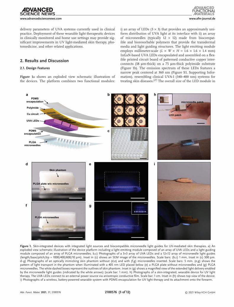
Figure 1. Skin-integrated devices with integrated light sources and biocompatible microneedle light guides for UV-mediated skin therapies. a) An exploded view schematic illustration of the device platform including a light emitting module composed of an array of UVA LEDs and a light guiding module composed of an array of PLGA microneedles. b,c) Photographs of a 3×3 array of UVA LEDs and a 12×12 array of microneedle light guides (length/base/pitch/tip = 1000/400/600/10 µm). Inset in (c) shows an SEM image of the microneedles. Scale bars: (b,c) 1 mm, Inset in (c) 500 µm. d–g) Photographs of an optically mimicking skin phantom without (d,e) and with (f,g) microneedles inserted. Scale bars: 5 mm. (e,g) shows the pattern of light transport in the phantom when illuminated with a 405 nm LED placed below (e) a PLGA plate without microneedles and (g) PLGA microneedles. The white dashed boxes represent the outlines of skin phantom. Inset in (g) shows a magnified view of the extended light delivery enabled by the microneedle light guides (indicated by the white arrows) (scale bar: 1 mm). h) Photographs of a skin-integrated, wearable device for UV light therapy. The UVA LEDs connect to an external power source via anisotropic conductive film. Scale bar: 1 cm. Inset in (h) shows top view of the device. i) Photographs of a wireless, battery-powered wearable system with PDMS encapsulation for UV light therapy and its attachment onto the forearm.
Adv. Funct. Mater. 2021, 31, 2100576

www.afm-journal.dewww.advancedsciencenews.com
2100576 (4 of 12) © 2021 Wiley-VCH GmbH
the current design (about 6 mm × 6 mm) enables treatment of individual, targeted skin lesions. The LEDs in the array operate in a parallel fashion, although programmable control of each LED can be achieved with simple modifications. The size of the patch, the arrangement of the LEDs, and the wavelengths of the emitted light can also be easily adjusted to meet requirements for different applications. Encapsulation of the patch with a thin layer of polydimethylsiloxane (PDMS, <100 µm in thick-ness) electrically insulates the LEDs and ensures their stable operation against sweat and other body fluids, as demonstrated in a variety of skin-integrated and implantable electronics in previous reports.[5,28] The PDMS, which is transparent to UVA light, also serves as a spacer and bonding layer between the LEDs and the light guiding module.
This module exploits dense arrays of long, pyramidal microneedles of a bioresorbable polymer (PLGA) on a thick base layer (up to 1 mm) of the same material. The choice of PLGA follows from considerations in aspects of biocompat-ibility, mechanical strength, optical properties, and fabrication methods. As a block copolymer composed of polylactic acid and polyglycolic acid, PLGA is extensively used in pharmaceu-tical and medical products, including recent demonstrations in patches for slow drug release.[14,24] Choices of ratios between the two components, molecular weights, functional groups, degree of crosslinking and crystallinity and others, provide access to formulations of PLGA with properties tailored for targeted bio-medical applications. The Young’s moduli of PLGA polymers used in this work (polylactic acid/polyglycolic acid = 85%/15% with a molecular weight of 50–75 K) are 1–2 GPa,[10,29,30] which, in geometric designs with sharp tips (≈10 µm in diameter), pro-vide capabilities for penetrating human skin (Young’s moduli in the order of 100 kPa[31]) without reaching the fracture limits.[30] The high transmittance of PLGA in the UVA region (about 98% for 1 mm thick films, see Figure S2 in the Supporting Infor-mation) minimizes absorption losses. The refractive index (≈1.46,[32] comparable to those of human skin, 1.38–1.48)[33] ena-bles spatially extensive light delivery over the skin/microneedle interface. In addition, the approximate index match between PLGA and PDMS (1.46 and 1.43) leads to low reflection losses between these two materials at the bonding interface with the LED module.
Fabrication of the microneedle arrays involves PDMS nega-tive molds with microneedle-shaped cavities formed by laser ablation, followed by filling these molds with PLGA melts under vacuum,[30] and finally cooling to room temperature and release, as depicted in Figure S3 (Supporting Information). Figure S4 (Supporting Information) shows optical and scan-ning electron microscope (SEM) images of PLGA microneedle arrays created in this fashion with different configurations (needle length up to 2 mm). Densely arranged microneedles with high occupancy (defined by the sum of base areas of the microneedles divided by the total area of the device) avoid inef-ficient light exposure between adjacent microneedles. Such configurations of microneedles, however, also lead to high mechanical resistance and damage to the skin upon insertion, presumably from the displacements of expelled skin tissues. Figure 1c shows an optical image of microneedle arrays with dimensional parameters that balance these two considera-tions (length of 1 mm, base size of 400 µm, tip size of around
10 µm, and pitch of 600 µm, a 12 × 12 array). The length of the microneedles (1 mm) allows delivery of light into the dermis of the skin across all non-acral locations without introducing significant discomfort.[34,35] For reference, biocompatible poly-meric microneedles with lengths between several hundreds of microns and 1.5 mm have been used for transdermal drug delivery, vaccination, and others on animal models and human subjects.[21,24,36]
Simple demonstrations using synthetic skin phantoms illus-trate the ability of the microneedles to qualitatively improve the depth of light penetration (Figure 1d–g). Details on preparation of gel-based skin phantoms with skin-mimicking optical prop-erties appear in the Experimental Section. The use of violet-blue light (emission centered at 405 nm) instead of UVA enables visualization of the distribution of light that passes through microneedle arrays placed near the edge of the phantom. The white dashed boxes in Figure 1e,g represent the outlines of the skin phantom. Under the same illumination intensity of violet-blue light from the bottom of the PLGA plate, the presence of PLGA microneedles clearly enhances the penetration of violet-blue light into the skin phantom. The inset in Figure 1g shows how light transports along the microneedle guides and spreads into the space between the microneedles as well as deep in the skin phantom. The dependence of the extinction coefficients of human skin on wavelength suggests that enhancements in light penetration enabled by microneedles for violet-blue wave-length also applies to UV light. The microneedles retain their structures and transparency after insertion in gel-based skin phantom for at least 1 h, which is sufficiently long for a UVA phototherapy session. The slow kinetics in bioresorption and degradation of these PLGA microneedles are consistent with previously reported implantable devices made from PLGA with similar compositions and preparation methods.[4,16] For instance, PLGA devices show modest changes in optical prop-erties after immersion in phosphate-buffered saline at 37 °C within a couple of hours[16] and largely preserve their transpar-ency and shapes after subcutaneously implanted in live mice for 6 days.[4]
Connecting the devices to external power sources yields functional units for UVA light therapy (Figure 1h). The small form factors and the adhesion forces from microneedle insertion allow convenient attachment on the forearms, as representative locations for scleroderma, with the aid of biocompatible tapes. Powering the system with a rechargeable, 45 mAh lithium ion battery enclosed in a water-resistant elastomeric silicone encapsulation, as described in a recent report,[37] enables wire-less operation and skin attachment (Figure 1i). The battery supports operation at a light intensity of >100 mW cm−2 for about 60 min (Figure S5, Supporting Information), sufficient for low to high dose therapy in treatments of morphea.[6] For example, a 20 min session of irradiation at 100 mW cm−2 leads to a dose at the surface of the skin of 120 J cm−2, typical for high dose therapy. Adding voltage and power control modules to the current system can enable adjustable light power output for dif-ferent therapeutic procedures. After each light treatment ses-sion, the microneedles can be replaced. The electronic parts are reusable. Such systems offer potential for convenient, low-cost, home-based, targeted UV therapy of skin disorders, especially those featuring fibrotic deposition in the deep dermis.
Adv. Funct. Mater. 2021, 31, 2100576
www.afm-journal.dewww.advancedsciencenews.com
2100576 (5 of 12) © 2021 Wiley-VCH GmbH
2.2. Electrical, Thermal, and Optical Management of the UVA LED Patches
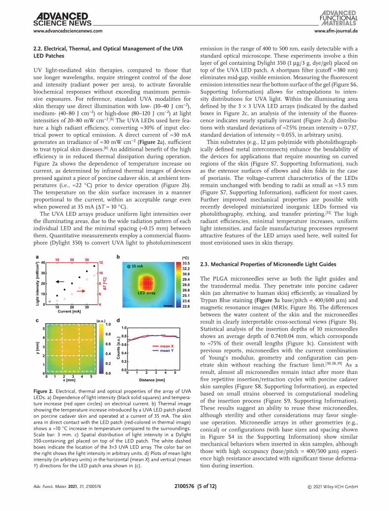
UV light-mediated skin therapies, compared to those that use longer wavelengths, require stringent control of the dose and intensity (radiant power per area), to activate favorable biochemical responses without exceeding maximum permis-sive exposures. For reference, standard UVA modalities for skin therapy use direct illumination with low- (10–40 J cm−2), medium- (40–80 J cm−2) or high-dose (80–120 J cm−2) at light intensities of 20–80 mW cm−2.[6] The UVA LEDs used here fea-ture a high radiant efficiency, converting ≈30% of input elec-trical power to optical emission. A direct current of ≈30 mA generates an irradiance of ≈30 mW cm−2 (Figure 2a), sufficient to treat typical skin diseases.[6] An additional benefit of the high efficiency is in reduced thermal dissipation during operation. Figure 2a shows the dependence of temperature increase on current, as determined by infrared thermal images of devices pressed against a piece of porcine cadaver skin, at ambient tem-peratures (i.e., ≈22 °C) prior to device operation (Figure 2b). The temperature on the skin surface increases in a manner proportional to the current, within an acceptable range even when powered at 35 mA (ΔT ≈ 10 °C).
The UVA LED arrays produce uniform light intensities over the illuminating areas, due to the wide radiation pattern of each individual LED and the minimal spacing (≈0.15 mm) between them. Quantitative measurements employ a commercial fluoro-phore (Dylight 350) to convert UVA light to photoluminescent
emission in the range of 400 to 500 nm, easily detectable with a standard optical microscope. These experiments involve a thin layer of gel containing Dylight 350 (1 µg/3 g, dye/gel) placed on top of the UVA LED patch. A shortpass filter (cutoff ≈380 nm) eliminates mid-gap, visible emission. Measuring the fluorescent emission intensities near the bottom surface of the gel (Figure S6, Supporting Information) allows for extrapolations to inten-sity distributions for UVA light. Within the illuminating area defined by the 3 × 3 UVA LED arrays (indicated by the dashed boxes in Figure 2c, an analysis of the intensity of the fluores-cence indicates nearly spatially invariant (Figure 2c,d) distribu-tions with standard deviations of ≈7.5% (mean intensity = 0.737, standard deviation of intensity = 0.055, in arbitrary units).
Thin substrates (e.g., 12 µm polyimide with photolithograph-ically defined metal interconnects) enhance the bendability of the devices for applications that require mounting on curved regions of the skin (Figure S7, Supporting Information), such as the extensor surfaces of elbows and skin folds in the case of psoriasis. The voltage–current characteristics of the LEDs remain unchanged with bending to radii as small as ≈3.5 mm (Figure S7, Supporting Information), sufficient for most cases. Further improved mechanical properties are possible with recently developed miniaturized inorganic LEDs formed via photolithography, etching, and transfer printing.[11] The high radiant efficiencies, minimal temperature increases, uniform light intensities, and facile manufacturing processes represent attractive features of the LED arrays used here, well suited for most envisioned uses in skin therapy.
2.3. Mechanical Properties of Microneedle Light Guides
The PLGA microneedles serve as both the light guides and the transdermal media. They penetrate into porcine cadaver skin (an alternative to human skin) efficiently, as visualized by Trypan Blue staining (Figure 3a base/pitch = 400/600 µm) and magnetic resonance images (MRIs; Figure 3b). The differences between the water content of the skin and the microneedles result in clearly interpretable cross-sectional views (Figure 3b). Statistical analysis of the insertion depths of 10 microneedles shows an average depth of 0.74±0.04 mm, which corresponds to ≈75% of their overall lengths (Figure 3c). Consistent with previous reports, microneedles with the current combination of Young’s modulus, geometry and configuration can pen-etrate skin without reaching the fracture limit.[30,38,39] As a result, almost all microneedles remain intact after more than five repetitive insertion/retraction cycles with porcine cadaver skin samples (Figure S8, Supporting Information), as expected based on small strains observed in computational modeling of the insertion process (Figure S9, Supporting Information). These results suggest an ability to reuse these microneedles, although sterility and other considerations may favor single-use operation. Microneedle arrays in other geometries (e.g., conical) or configurations (with base sizes and spacing shown in Figure S4 in the Supporting Information) show similar mechanical behaviors when inserted in skin samples, although those with high occupancy (base/pitch = 400/500 µm) experi-ence high resistance associated with significant tissue deforma-tion during insertion.
Figure 2. Electrical, thermal and optical properties of the array of UVA LEDs. a) Dependence of light intensity (black solid squares) and tempera-ture increase (red open circles) on electrical current. b) Thermal image showing the temperature increase introduced by a UVA LED patch placed on porcine cadaver skin and operated at a current of 35 mA. The skin area in direct contact with the LED patch (red-colored in thermal image) shows a ≈10 °C increase in temperature compared to the surroundings. Scale bar: 3 mm. c) Spatial distribution of light intensity in a Dylight 350-containing gel placed on top of the LED patch. The white dashed boxes indicate the location of the 3×3 UVA LED array. The color bar on the right shows the light intensity in arbitrary units. d) Plots of mean light intensity (in arbitrary units) in the horizontal (mean X) and vertical (mean Y) directions for the LED patch area shown in (c).
Adv. Funct. Mater. 2021, 31, 2100576

www.afm-journal.dewww.advancedsciencenews.com
2100576 (6 of 12) © 2021 Wiley-VCH GmbH
Slightly modified fabrication methods allow formation of light guiding modules with bendable base layers. In the cur-rent process, the PLGA melts and partially crystallizes, to yield semicrystalline states after cooling to room temperature.[40] This state results in mechanically robust microneedles for skin penetration, but with a base layer that does not offer suf-ficient flexibility to conform to curved regions of the skin. A scheme to overcome this limitation involves treating the base layer (≈0.2 mm in thickness) with solvents such as ethyl acetate (as drops or in vapor form) without exposing the microneedles (see the Experimental Section). This process induces semicrys-talline-amorphous transitions in the base layer to enhance its mechanical flexibility, without changing the mechanical prop-erties of the microneedles. As illustrated in the stress-strain curves of Figure S10 (Supporting Information), as-molded PLGA without solvent-assisted treatment exhibits a Young’s modulus of ≈0.9 GPa within a linear elastic regime (strain <0.16%). In contrast, PLGA after this treatment shows a hyper-elastic material response with an initial modulus of 6 MPa, which is more than two orders of magnitude lower than that of the pristine PLGA. The distinctly different moduli of the microneedles (PLGA without softening) and the base layer (PLGA after softening) allow for bending required for mounting on curved skin while maintaining the mechanical robustness of microneedles needed for skin penetration, as in Figure 3d and Figure S11 (Supporting Information). The experimental observations agree well with finite element analysis (FEA) in both cases (Figure 3e and Figure S11: Supporting Information). The spatial maximum of the maximum principal strain in the microneedles is ≈0.01% near the bases of the microneedles, which is well within the elastic regime of the PLGA without softening. The bendable base layers enhance the applicability
of microneedles to curved regions of skin. Mechanical simu-lations (on models including skin layer, UVA LED patch, and encapsulation enclosure) and further optimization in device designs are necessary to reduce the variation in skin insertion depths of microneedles at different locations of the curved skin.
2.4. Light Guiding Properties of Microneedles
The patterns of illumination provided by the microneedles determine the efficacy of use in deep skin therapy. Standard methods to analyze glass or bioresorbable waveguides for vis-ible light, in the form of optical fibers, thin slabs and others, employ cutback techniques, optical microscopy analysis, and other methods to evaluate guiding performance.[4,12–16] In our case, a combination of strong attenuation of UVA light by the skin, difficulties in directly detecting UVA light in situ, and the extreme shapes of the microneedles creates challenges in the use of such techniques. At a basic level, top-view optical images (Figure S12, Supporting Information) of porcine cadaver skin (thickness of ≈1 mm) inserted with microneedles show significantly enhanced transmission of 405 nm light, as an alternative to UVA light to facilitate detection.
Numerical calculations using Monte Carlo methods provide quantitative insights into the transmission, propagation, and distribution of UV light inside and outside the microneedles at various skin depths. The simulations use optical parameters of epidermal and dermal layers of human skin, as summarized in previous reports.[41] For simplicity, we use the term “skin” in the following discussions. Details appear in the Experimental Section. Figure 4a compares the 2D profiles of light distribu-tion (normalized with respect to the light intensity at the skin
Figure 3. Mechanical properties of PLGA microneedle light guides. a) Top view of porcine skin cadaver after insertion and removal of microneedles and stained by Trypan blue. b) Cross-sectional magnetic resonance images of a porcine skin cadaver with PLGA microneedles inserted. c) Statistics of insertion depth of microneedles based on analysis of (b). d) Photographs of microneedles with the handling layer bent outward and inward. e) Distri-bution of the maximum principal strain determined by 3D FEA modeling of the microneedles shown in (d). Scale bars: 1 mm.
Adv. Funct. Mater. 2021, 31, 2100576
www.afm-journal.dewww.advancedsciencenews.com
2100576 (7 of 12) © 2021 Wiley-VCH GmbH
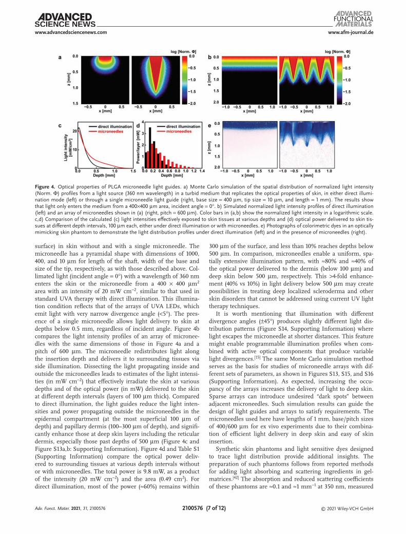
surface) in skin without and with a single microneedle. The microneedle has a pyramidal shape with dimensions of 1000, 400, and 10 µm for length of the shaft, width of the base and size of the tip, respectively, as with those described above. Col-limated light (incident angle = 0°) with a wavelength of 360 nm enters the skin or the microneedle from a 400 × 400 µm2 area with an intensity of 20 mW cm−2, similar to that used in standard UVA therapy with direct illumination. This illumina-tion condition reflects that of the arrays of UVA LEDs, which emit light with very narrow divergence angle (<5°). The pres-ence of a single microneedle allows light delivery to skin at depths below 0.5 mm, regardless of incident angle. Figure 4b compares the light intensity profiles of an array of micronee-dles with the same dimensions of those in Figure 4a and a pitch of 600 µm. The microneedle redistributes light along the insertion depth and delivers it to surrounding tissues via side illumination. Dissecting the light propagating inside and outside the microneedles leads to estimates of the light intensi-ties (in mW cm−2) that effectively irradiate the skin at various depths and of the optical power (in mW) delivered to the skin at different depth intervals (layers of 100 µm thick). Compared to direct illumination, the light guides reduce the light inten-sities and power propagating outside the microneedles in the epidermal compartment (at the most superficial 100 µm of depth) and papillary dermis (100–300 µm of depth), and signifi-cantly enhance those at deep skin layers including the reticular dermis, especially those past depths of 500 µm (Figure 4c and Figure S13a,b: Supporting Information). Figure 4d and Table S1 (Supporting Information) compare the optical power deliv-ered to surrounding tissues at various depth intervals without or with microneedles. The total power is 9.8 mW, as a product of the intensity (20 mW cm−2) and the area (0.49 cm2). For direct illumination, most of the power (≈60%) remains within
300 µm of the surface, and less than 10% reaches depths below 500 µm. In comparison, microneedles enable a uniform, spa-tially extensive illumination pattern, with ≈80% and ≈40% of the optical power delivered to the dermis (below 100 µm) and deep skin below 500 µm, respectively. This >4-fold enhance-ment (40% vs 10%) in light delivery below 500 µm may create possibilities in treating deep localized scleroderma and other skin disorders that cannot be addressed using current UV light therapy techniques.
It is worth mentioning that illumination with different divergence angles (±45°) produces slightly different light dis-tribution patterns (Figure S14, Supporting Information) where light escapes the microneedle at shorter distances. This feature might enable programmable illumination profiles when com-bined with active optical components that produce variable light divergences.[15] The same Monte Carlo simulation method serves as the basis for studies of microneedle arrays with dif-ferent sets of parameters, as shown in Figures S13, S15, and S16 (Supporting Information). As expected, increasing the occu-pancy of the arrays increases the delivery of light to deep skin. Sparse arrays can introduce undesired “dark spots” between adjacent microneedles. Such simulation results can guide the design of light guides and arrays to satisfy requirements. The microneedles used here have lengths of 1 mm, base/pitch sizes of 400/600 µm for ex vivo experiments due to their combina-tion of efficient light delivery in deep skin and easy of skin insertion.
Synthetic skin phantoms and light sensitive dyes designed to trace light distribution provide additional insights. The preparation of such phantoms follows from reported methods for adding light absorbing and scattering ingredients in gel-matrices.[42] The absorption and reduced scattering coefficients of these phantoms are ≈0.1 and ≈1 mm−1 at 350 nm, measured
Figure 4. Optical properties of PLGA microneedle light guides. a) Monte Carlo simulation of the spatial distribution of normalized light intensity (Norm. Φ) profiles from a light source (360 nm wavelength) in a turbid medium that replicates the optical properties of skin, in either direct illumi-nation mode (left) or through a single microneedle light guide (right, base size = 400 µm, tip size = 10 µm, and length = 1 mm). The results show that light only enters the medium from a 400×400 µm area, incident angle = 0°. b) Simulated normalized light intensity profiles of direct illumination (left) and an array of microneedles shown in (a) (right, pitch = 600 µm). Color bars in (a,b) show the normalized light intensity in a logarithmic scale. c,d) Comparison of the calculated (c) light intensities effectively exposed to skin tissues at various depths and (d) optical power delivered to skin tis-sues at different depth intervals, 100 µm each, either under direct illumination or with microneedles. e) Photographs of colorimetric dyes in an optically mimicking skin phantom to demonstrate the light distribution profiles under direct illumination (left) and in the presence of microneedles (right).
Adv. Funct. Mater. 2021, 31, 2100576

www.afm-journal.dewww.advancedsciencenews.com
2100576 (8 of 12) © 2021 Wiley-VCH GmbH
by the Inverse Adding-Doubling method (Figure S17, Supporting Information).[43] These values are of the same order of magnitude as reported values (absorption coefficients: 0.3–1 mm−1, reduced scattering coefficients: 1–10 mm−1, at 350 nm, depending on different sources and conditions of measurements) and those used in our Monte Carlo simula-tions.[41] Adding a mixture of potassium ferricyanide, ferric ammonium citrate, and potassium dichromate to the syn-thetic skin phantom enables imaging of UV dose based on the cyanotype photochemistry. In brief, upon UV irradiation, the citrate reduces Fe (III) to Fe (II). The Fe (II) ions then react with ferricyanide to produce ferric ferrocyanide, an insoluble blue dye also known as Prussian blue. Soaking the gel-phantom in water dissolves the unreacted reagents while the Prussian blue traces remain in the gel. Figure 4e shows the exposure patterns evaluated in this manner, for cases without and with microneedles. In the former, only the top layers are blue, due to the limited penetration depth. The blue shades in the latter case occupy the space between individual microneedles and spread deep in the phantom, replicating the simulated light distribu-tion profiles (Figure 4e). As the photogenerated Prussian blue cannot migrate in the phantom, the outlines of the blue patterns define the boundaries of UV-exposed regions with a minimal dose to activate the photoreactions. Analysis of the color inten-sities in Figure 4e (integrated over the whole image at various depths) reflects the dependence of effective light dose on pen-etrating depth. This relation resembles the simulated changes in total power at different depths, as shown in Figure S13a,c (Supporting Information). In both the experimental and
simulated cases, the microneedles significantly enhance the light delivery to deep skin layers.
2.5. Ex Vivo Human Skin Explant Culture Experiments
The function of these integrated UVA light therapy devices can be demonstrated with ex vivo human skin explant cul-tures. Using skin samples from normal tissue donors, we compared UVA-induced biological responses by the described microneedle-assisted light therapy device (MN, Figure 5a,b) to direct illumination with a UVA lamp (LAMP, to emulate the standard UVA light therapy). The sterilization of micronee-dles prior to their insertion in skin explant cultures relies on rinsing with alcohol. For medical applications, conventional and emerging methods (e.g., irradiation) can provide effective forms of sterilization, while largely preserving the properties of the microneedles.[44] Fabrication and assembly in biological safety cabinets yield sterile microneedles and related devices applicable to studies involving human participants, as sug-gested by a recent report on effervescent PLGA microneedle patches.[24] Doses of 13.5 and 67.5 J cm−2 simulate clinically rel-evant low (10–40 J cm−2)- and moderate (40–80 J cm−2) ranges used in UVA therapeutic modalities.[6] Potential toxicity, an adverse side effect of phototherapy to the epidermis that can lead to “sun-burnt” skin and cellular DNA damage,[45] is rel-evant to the light doses in epidermis. As suggested by Monte Carlo simulation and optical measurements, microneedles dis-tribute optical power to depths that correspond to deep skin
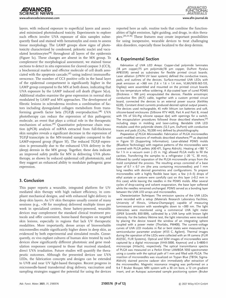
Figure 5. Results of experiments on ex vivo human skin explant cultures. a,b) Photographs of integrated devices laminated on ex vivo human skin explant cultures with microneedles inserted. Scale bar: 1 cm. c) Representative images of hematoxylin and eosin stained cross sections of skin tissue exposed to UVA light by direct illumination (LAMP) or with light therapy device with microneedle guides (MN). Insets show magnified view of images in the black dashed box, highlighting the differences in cell damage in the LAMP and MN groups. d) Representative images of skin tissue stained with cleaved caspase 3 (CC3) antibody and detected with a far-red fluorescent probe (magenta). Insets show positive staining in the basal layer of LAMP-exposed skin tissue, with little to no staining present in the MN group. #, nonspecific staining in the stratum corneum. Scale bars in (c,d): 50 µm. Dashed lines represent the compartmentalization between the epidermis and dermis. e) Quantification of CC3-positive basal keratinocytes in LAMP versus MN groups. ***, P < 0.0001 by two-way ANOVA followed by Sidak’s multiple comparisons test. n = 2 for 13.5 J cm−2 and n = 3 for 67.5 J cm−2. f) Analysis of TGFβ transcripts, TGFB1, by qPCR. *, P = 0.0336 by unpaired, two-tailed t-test. n = 2.
Adv. Funct. Mater. 2021, 31, 2100576
www.afm-journal.dewww.advancedsciencenews.com
2100576 (9 of 12) © 2021 Wiley-VCH GmbH
layers, with reduced exposure to superficial layers and associ-ated minimized photoinduced toxicity. Experiments to explore such effects involve UVA exposure of skin samples subse-quently fixed and stained with hematoxylin and eosin to assess tissue morphology. The LAMP groups show signs of photo-toxicity characterized by condensed, pyknotic nuclei and vacu-olated keratinocytes[46] throughout all layers of the epidermis (Figure 5c). These changes are absent in the MN group. To complement the morphological assessment, we stained tissue sections to detect in situ expression for cleaved caspase 3 (CC3), a biochemical marker and effector molecule of cell death asso-ciated with the apoptosis cascade,[47] using indirect immunoflu-orescence. The number of CC3 positive cells in the basal layer of the epidermal compartment is significantly higher in the LAMP group compared to the MN at both doses, indicating that UVA exposure by the LAMP induced cell death (Figure 5d,e). Additional studies examine the gene expression in normal skin modulated by LAMP and MN approaches. The development of fibrotic lesions in scleroderma involves a combination of fac-tors including dysregulated collagen metabolism from trans-forming growth factor beta (TGFβ) overproduction.[48] UVA phototherapy can reduce the expression of this pathogenic molecule, an event that plays a critical role in the therapeutic mechanism of action.[49] Quantitative polymerase chain reac-tion (qPCR) analysis of mRNA extracted from full-thickness skin samples reveals a significant decrease in the expression of TGFβ transcripts in the MN-treated samples compared to the LAMP-exposed group (Figure 5f). The reduced TGFβ expres-sion is presumably due to the enhanced UVA delivery in the (deep) dermis in the MN group. Together, these data indicate an improved safety profile for MN in delivering UVA photo-therapy, as shown by reduced epidermal cell phototoxicity, and they suggest an enhanced ability to modulate pathogenic gene expression.
3. Conclusion
This paper reports a wearable, integrated platform for UV-mediated skin therapy with high radiant efficiency, in com-pliant mechanical designs, and with enhanced light delivery in deep skin layers. As UV skin therapies usually consist of many sessions (e.g., ≈30 for morphea) delivered multiple times per week in specialized centers, these battery-powered, wearable devices may complement the standard clinical treatment pro-tocols and offer convenient, home-based therapies on targeted skin lesions, especially in regions that lack UV therapeutic modalities. More importantly, dense arrays of bioresorbable microneedles enable significantly higher doses in deep skin, as evidenced by both experimental and simulated results. Conse-quently, ex vivo explant cultures of human skin treated by such devices show significantly different phototoxic and gene mod-ulation responses compared to those that received standard, direct UVA irradiation. Future studies will quantify the thera-peutic outcomes. Although the presented devices use UVA LEDs, the fabrication concepts and designs can be extended to UVB and near UV light-based therapies. Recent progress in microneedle-based transdermal drug delivery, vaccination and sampling strategies suggest the potential for using the devices
reported here as safe, routine tools that combine the function-alities of light emission, light guiding, and drugs, in skin thera-pies.[20,24,36] These features may create important possibilities for using inexpensive, wearable devices to treat challenging skin disorders, especially those localized to the deep dermis.
4. Experimental SectionFabrication of UVA LED Arrays: Copper-clad polyimide laminates
(18 µm copper/75 µm polyimide/18 µm copper, DuPont Pyralus AP8535R) served as substrates for flexible printed circuit boards. Laser ablation (LPKF4 UV laser system) defined the conductive traces, pads, and outlines of the devices. Surface-mounted UVA LEDs with peak emission at ≈360 nm (1.6 × 1.6 × 1.4 mm, VLMU1610-365-135, Digikey) were assembled and mounted on the printed circuit boards by low temperature reflow soldering. A dip-coated layer of cured PDMS (thickness < 100 µm) encapsulated the devices. Flexible anisotropic conductive film (ACF) cable, together with a custom printed circuit board, connected the devices to an external power source (Keithley 6220). Constant direct currents produced desired optical output powers. The devices used rechargeable, 45 mAh lithium ion batteries and soft, silicone-based enclosures (Silbione RTV 4420, Part A and Part B, mixed with 5% of Silc-Pig silicone opaque dye) with openings for a switch. The encapsulation procedures followed those described elsewhere,[37] including steps in molding and laser-cutting. Bendable UVA LED modules used thin polyimide sheets (12.5 µm, DuPont) with conductive traces and pads (Cr/Au, 10/200 nm) defined by photolithography.
Preparation of PLGA Microneedles: Fabrication of PLGA microneedles used modified versions of methods described elsewhere,[30] as depicted in Figure S3 (Supporting Information). Laser-ablated PDMS molds (BlueAcre Technology) with negative patterns of the microneedles were covered with PLGA pellets (430 471, Sigma Aldrich). Heating at ≈180 °C for 1 h in a vacuum oven (−25 in. Hg) allowed PLGA melts to fill the cavities. Transferring the samples to a refrigerator (−20 °C, 30 min), followed by careful separation of the PLGA microneedle arrays from the mold completed the process. The resulting arrays consisted of a base layer of 0.7 × 0.7 cm (the area containing microneedles) and 1 mm long needles with desired geometries and configurations. To prepare microneedles with a highly flexible base layer, a few (≈3–5) drops of ethyl acetate or acetone were carefully cast on this layer (≈0.2 mm in this case) while leaving the needles in the PDMS molds. After several cycles of drop-casting and solvent evaporation, the base layer softened while the needles remained unchanged. PDMS served as a bonding layer between the UVA LED arrays and microneedles.
Characterization Techniques: The emission spectra of the UVA LEDs were recorded with a setup (Materials Research Laboratory Facilities, University of Illinois, Urbana-Champaign) capable of measuring luminescent emission with wavelengths down to ≈300 nm. The light intensities were monitored using a commercial UVA light meter (SPER Scientific 850 009), calibrated by a UVA lamp with known light intensity. For the battery lifetime test, the light intensities were recorded by placing the device toward the window of an integrating sphere coupled with a power meter (Thorlabs, PM400). The current–voltage curves of UVA LED modules in flat or bent states were measured by a semiconductor parameter analyzer (4155 C, Agilent). Thermal images during the operation of the LEDs were collected with an IR camera (FLIR A325SC, FLIR Systems). Optical and SEM images of microneedles were captured by a digital microscope (VHX-5000, Keyence) and a S-4800-II microscope (Hitachi), respectively. The optical transmittance spectra of PLGA was measured on a Perkin Elmer LAMBDA 1050 spectrometer using a cuvette with the optical path of 1 mm and filled with PLGA. The insertion of microneedles was visualized on Trypan Blue (T8154, Sigma-Aldrich) stained porcine cadaver skin immediately after extraction of the microneedles. Magnetic resonance imaging was performed on a 9.4 T Bruker Biospec MRI system with a 30 cm bore, a 12 cm gradient insert, and an Autopac automated sample positioning system (Bruker
Adv. Funct. Mater. 2021, 31, 2100576

www.afm-journal.dewww.advancedsciencenews.com
2100576 (10 of 12) © 2021 Wiley-VCH GmbH
Biospin Inc, Billerica, MA). Optical images showing the light intensity distribution of UVA LEDs and light transport in porcine cadaver skin through microneedles were collected with a Leica DM6B Widefield Fluorescent Microscope. In the former, a short pass filter (cut-off at 380 nm) blocked midgap emissions from the UVA LED module in the visible light region. A piece of Dylight 350 (Thermo Scientific) containing Agarose gel (4 wt% Agarose gel made from Agarose powder, Thermo Scientific) placed on top of the short pass filter and the LED module converted UVA to blue light detectable by the optical microscope. The weight ratio of Dylight 350 to Agarose gel was 1 µg/3 g. The light intensity distribution of UVA LEDs was extrapolated by analyzing the fluorescence images. To compare the light penetration depths in porcine cadaver skin with or without microneedles, commercial 405 nm LEDs were used as alternative to the UVA LED modules, to permit direct imaging of transmitted light by the optical microscope.
Mechanical Characterization and Finite Element Analysis (FEA) of the Microneedles: Tensile testing of PLGA samples (≈30 × 5 × 1.5 mm in size) using a dynamic mechanical analyzer (DMA, TA Instruments RSA-G2) revealed the mechanical properties of PLGA without and with the solvent-assisted softening treatment. Stress–strain responses obtained from axial tensile testing yielded the mechanical properties used in 3D FEA analysis of mechanical deformations and stress concentrations associated with microneedles on a base layer upon bending. Ten-node quadratic tetrahedron elements (C3D10) were employed to model the PLGA microneedles, and eight-node linear brick elements (C3D8RH, hybrid, constant pressure, reduced integration, and hourglass control) were used for the base layer, using commercial software (ABAQUS). Refined meshes ensured computational accuracy. Linear elastic response was used to model the microneedle material, with modulus Eneedle = 0.9 GPa and the Poisson’s ratio νneedle = 0.3. Hyperelastic material response was used to model the base layer material, using the stress–strain response defined by fitting the measured stress–strain response as shown in Figure S10 (Supporting Information) using a polynomial form with 2nd order strain energy potential, with initial modulus Ehandling = 6 MPa and the Poisson’s ratio νhandling = 0.49.
FEA using the software Autodesk Fusion 360 yielded the strains and stresses experienced by a single microneedle during skin insertion. The simulated structure included a PLGA base layer (8.1 × 8.1 × 1.0 mm) and an array of 12 × 12 microneedles (length/tip/base/pitch sizes: 1 mm/10 µm/400 µm/600 µm). Modeling of these multilayered structures used four-node composite shell elements. Refined meshes ensured computational accuracy. The microneedles were modelled as linear elastic materials with Young’s modulus of 0.9 GPa and a Poisson’s ratio of 0.3. A force of 0.015 N per microneedle was applied to the microneedle tip normal to the base to approximate the maximum insertion force, according to a previous report.[50]
Monte Carlo Simulation on Light Transport in the Skin: Monte Carlo simulations[51] yielded the UV light illumination profiles in media with absorptive and scattering properties similar to those of human skin. The simulation included of a light source (360 nm, 20 mW cm−2) illuminating the skin i) in the presence of the microneedle light guides under two illumination conditions: without divergence (i.e., incident angle = 0°) and with divergence (divergence angle of ±45°); and ii) in the absence of the microneedles (i.e., direct illumination). The total optical power was PTotal = IT × AT = 9.8 mW, where IT = 20 mW cm−2, AT is the area of the microneedle module (0.7 × 0.7 cm). The power per microneedle unit cell (PMN) can be calculated as PMN = IT × AT/nMN, where nMN is the number of microneedle unit cells. Simulations of the optical properties of different skin layers used absorption and scattering coefficients and the anisotropy factor from previous reports for the UVA wavelength band and assume a 100 µm epidermis layer on top of the dermis.[41] Epidermis: absorption coefficient = 30.16 cm−1, scattering coefficient = 210.4 cm−1, anisotropy factor = 0.702; dermis: absorption coefficient = 20.74 cm−1, scattering coefficient = 212.7 cm−1, anisotropy factor = 0.715; PLGA: refractive index = 1.46.
Simulations for a single microneedle yielded representative illumination characteristics. This illumination profile can be divided
into two parts. One remains inside the physical boundaries of the microneedle, and the other corresponds to illumination outside the microneedle. The latter portion contributes to illumination of the surrounding tissue. The total power that the microneedle array delivers to the skin corresponds to the contribution from this single microneedle contained in a unit cell (period equal to the microneedle separation) multiplied by the total number of elements in the array. Important parameters obtained from these simulations include: 1) the local distributions of intensity around each microneedle and the microneedle array; 2) intensities delivered to the skin at various depths, defined as the portion of optical power outside the microneedles divided by the skin area (the difference of total area and the sum of cross-sectional area of microneedles, variable at different depths); 3) optical power (in mW) delivered to the skin at different depth intervals.
Optical Measurements in Skin Phantoms: Preparation of skin phantoms followed procedures in previous reports with slight modifications.[42] The phantoms contained Agarose (0.6 g), Intralipid (3.0 g, 20% emulsion, Sigma Aldrich), 10×TAE buffer solution (1.2 g, UltraPure, Thermo Scientific) and deionized water (10.8 g). Varying the amounts of Intralipid drastically altered the scattering properties of the phantoms. Applying Inverse Adding-Doubling method to reflection and transmission data measured with a spectrometer equipped with an integrating sphere (Perkin Elmer LAMBDA 1050) yielded the absorption coefficient, reduced scattering coefficient, and anisotropy factor of these phantoms. Tuning the concentration of intralipid yielded phantom skin with optical properties comparable to those of skin within the UV spectral regime. Cyanotype photochemistry allowed imaging of light propagation in phantoms with or without microneedle light guides. Aqueous solutions of potassium ferricyanide (8.1%), ferric ammonium citrate (20.0%), and potassium dichromate (1%) were prepared from corresponding chemicals purchased from Sigma Aldrich. The cyanotype chemistry relied on mixed solutions of potassium ferricyanide and ferric ammonium citrate in a 1:1 ratio (by volume) and a small amount of potassium dichromate solution (6 drops per 2 mL of solution). 2 mL of the cyanotype solution was added to that of a phantom consisting of 0.6 g of agarose, 3 g of intralipid, 1.2 g of 10×TAE buffer, and 10.8 g of deionized water. After boiling for a short time, the mixed solution was cooled naturally to yield a bright yellow, gel-like phantom with optical properties similar to human skin in the UV spectral range. UV exposed regions turned blue while unexposed regions remained yellow. Soaking the samples in water released the unexposed reagent, to form blue patterns that define the light propagation pathways. The exposure conditions that yielded the best results/contrast involved ≈30 mW cm−2 (similar to those used in Monte Carlo simulation) for 30 s. The results allowed comparisons of spatial distributions of UV exposure produced from various microstructures.
Ex Vivo Explant Skin Cultures and UVA Exposure: De-identified skin tissue was obtained from the Northwestern University Skin Tissue Engineering and Morphology Core collected under an approved protocol in compliance with the Northwestern University Internal Review Board (IRB# STU00009443). Tissue was exposed to UVA light by a handheld UV lamp (365 nm, ≈5 mW cm−2, as the replica of standard direct illumination approach, LAMP) or the UV light therapy systems (MN). The dimensions of the microneedles are length/base/tip/pitch = 1000/400/10/600 µm. Tissue was kept moist in a culture dish with phosphate buffered saline. For light therapy devices, microneedles were inserted into skin tissue with gentle pressure, the integrated devices were turned on, and the light intensity was kept at ≈5 or 10 mW cm−2 (for the low and medium dose, respectively) controlled by a Keithley source meter. The exposure doses were set to ≈13.5 (low dose) and ≈67.5 J cm−2 (medium dose), respectively, for both approaches. Following UVA exposure, samples were bisected. One portion was processed as a formalin-fixed, paraffin embedded specimen, and stained with hematoxylin and eosin to assess tissue morphology. The other portion was flash frozen for mRNA extraction.
Immunofluorescent Staining of Cleaved Caspase 3: Sections (4 µm) of formalin-fixed, paraffin-embedded tissue specimens were stained with cleaved caspase 3 antibody (Asp175) according to the manufacturer’s
Adv. Funct. Mater. 2021, 31, 2100576
www.afm-journal.dewww.advancedsciencenews.com
2100576 (11 of 12) © 2021 Wiley-VCH GmbH
protocol (Rabbit mAb [5A1E] #9664, Cell Signaling, Danvers, MA USA). A fluorescent-tagged secondary antibody was used to visualize the protein (donkey anti-rabbit AlexaFlour 647, Thermo Fisher Scientific, Waltham, MA USA). Images were captured with a Zeiss Axio Imager Z1 (Oberkochen, Germany). Positive basal epidermal cells were counted as a percent of the total number of basal epidermal cells. Statistical analysis included two-way ANOVA followed by Sidak’s multiple comparisons test.
Quantitative Polymerase Chain Reaction (qPCR): mRNA was extracted from skin tissue using the miRNeasy Mini Kit according to manufacturer’s instructions (Qiagen, Germantown, MD USA). cDNA was generated by reverse transcriptase using the SuperScript III First-Strand Synthesis Kit according to manufacturer’s instructions (Thermo Fisher). For qPCR analysis of TGFβ (TGFB1) transcripts the PrimerQuest Tool (Integrated DNA Technologies, Coralville, IA USA) was used to generate the following primer pair: forward 5′-CGTGGAGCTGTACCAGAAATAC-3′ and reverse: 3′- CACAACTCCGGTGACATCAA-5′. FastStart Essential DNA Green Master Mix was used for qPCR detection with a Lightcycler 96 System (Roche, Basel, Switzerland) using a standard protocol with primer melting point (Tm) of 62 °C. Statistical analysis included unpaired, two-tailed t-test.
Supporting InformationSupporting Information is available from the Wiley Online Library or from the author.
AcknowledgementsH. Zhang and H. Zhao contributed equally to this work. The authors thank J.A.N.D. Soares for the help in measuring emission spectra of UVA LEDs, C.R. Haney and A. Birkha for taking and analyzing MRI images, J. E. Hornick for assistance in optical imaging. H. Zhang acknowledges the support from the National Natural Science Foundation of China (Grant No. 21974079). J.Z. and S.X. acknowledge support from a medical student research grant from the National Psoriasis Foundation (C#127036). S.M. acknowledges the support from Indo-US Science and Technology Forum (Grant No. SERB-IUSSTF-2017/192). D.C. acknowledges the support from National Science Foundation (Grant No. ECCS-1808045). This research was supported by the Querrey-Simpson Institute for Bioelectronics at Northwestern University. This work used Northwestern University Micro/Nano Fabrication Facility (NUFAB), which is partially supported by Soft and Hybrid Nanotechnology Experimental (SHyNE) Resource (NSF ECCS-1542205), the Materials Research Science and Engineering Center (DMR-1720139), the State of Illinois, and Northwestern University; Biological imaging facility at Northwestern University; the Skin Tissue Engineering and Morphology Core of the Northwestern University Skin Biology and Diseases Resource-based Center (supported by NIH/NIAMS P30 AR075049); and facilities at Frederick Seitz Materials Research Laboratory for Advanced Science and Technology at the University of Illinois at Urbana-Champaign.
Conflict of InterestThe authors declare no conflict of interest.
Data Availability StatementThe data that support the findings of this study are available from the corresponding author upon reasonable request.
Keywordsbiocompatible microneedles, light waveguides, skin phototherapy, wearable devices
Received: January 19, 2021Revised: March 2, 2021
Published online: March 31, 2021
[1] G.-H. Lee, H. Moon, H. Kim, G. H. Lee, W. Kwon, S. Yoo, D. Myung, S.-H. Yun, Z. Bao, S. K. Hahn, Nat. Rev. Mater. 2020, 5, 149.
[2] S.-H. Yun, S. J. J. Kwok, Nat. Biomed. Eng. 2017, 1, 0008.[3] A. Bansai, F. Yang, T. Xi, Y. Zhang, J. S. Ho, Proc. Natl. Acad. Sci.
USA 2018, 115, 1469.[4] S. Nizamoglu, M. C. Gather, M. Humar, M. Choi, S. Kim, K. S. Kim,
S. K. Hahn, G. Scarcelli, M. Randolph, R. W. Redmond, S.-H. Yun, Nat. Commun. 2016, 7, 10374.
[5] H. E. Lee, S. H. Lee, M. Jeong, J. H. Shin, Y. Ahn, D. Kim, S. H. Oh, S. H. Yun, K. J. Lee, ACS Nano 2018, 12, 9587.
[6] N. M. Teske, H. T. Jacobe, Clin. Dermatol. 2016, 34, 614.[7] C. Fritsch, G. Goerz, T. Ruzicka, Arch. Dermatol. 1998, 134, 207.[8] M. R. Alexiades-Armenakas, R. G. Geronemus, Arch. Dermatol.
2003, 139, 1313.[9] J. Serup, Acta. Derm. -Venereol. 1984, 64, 214.
[10] P. Sarazin, X. Roy, B. D. Favis, Biomaterials 2004, 25, 5965.[11] H. Zhang, J. A. Rogers, Adv. Opt. Mater. 2019, 7, 1800936.[12] M. A. Kosoglu, R. L. Hood, Y. Chen, Y. Xu, M. N. Rylander,
C. G. Rylander, J. Biomech. Eng. 2010, 132, 091014.[13] M. Choi, J. W. Choi, S. Kim, S. Nizamoglu, S. K. Hahn, S. H. Yun,
Nat. Photonics 2013, 7, 987.[14] S. Shabahang, S. Kim, S.-H. Yun, Adv. Funct. Mater. 2018, 28,
1706635.[15] M. Kim, J. An, K. S. Kim, M. Choi, M. Humar, S. J. J. Kwok, T. Dai,
S.-H. Yun, Biomed. Opt. Express 2016, 7, 4220.[16] W. Bai, J. Shin, R. Fu, I. Kandela, D. Lu, X. Ni, Y. Park, Z. Liu,
T. Hang, D. Wu, Y. Liu, C. R. Haney, I. Stepien, Q. Yang, J. Zhao, K. R. Nandoliya, H. Zhang, X. Sheng, L. Yin, K. MacRenaris, A. Brikha, F. Aird, M. Pezhouh, J. Hornick, W. Zhou, J. A. Rogers, Nat. Biomed. Eng. 2019, 3, 644.
[17] S. Y. Heo, J. Kim, P. Gutruf, A. Banks, P. Wei, R. Pielak, G. Balooch, Y. Shi, H. Araki, D. Rollo, C. Gaede, M. Patel, J. W. Kwak, A. E. Pena-Alcantara, K.-T. Lee, Y. Yun, J. K. Robinson, S. Xu, J. A. Rogers, Sci. Transl. Med. 2018, 10, eaau1643.
[18] H. Zhang, P. Gutruf, K. Meacham, M. C. Montana, X. Zhao, A. M. Chiarelli, A. Vazquez-Guadado, A. Norris, L. Lu, Q. Guo, C. Xu, Y. Wu, H. Zhao, X. Ning, W. Bai, I. Kandela, C. R. Haney, D. Chanda, R. W. I. Gereau, J. A. Rogers, Sci. Adv. 2019, 5, eaaw0873.
[19] H. U. Chung, B. H. Kim, J. Y. Lee, J. Lee, Z. Xie, E. M. Ibler, K. Lee, A. Banks, J. Y. Jeong, J. Kim, C. Ogle, D. Grande, Y. Yu, H. Jang, P. Assem, D. Ryu, J. W. Kwak, M. Namkoong, J. B. Park, Y. Lee, D. H. Kim, A. Ryu, J. Jeong, K. You, B. Ji, Z. Liu, Q. Huo, X. Feng, Y. Deng, Y. Xu, K.-I. Jang, J. Kim, Y. Zhang, R. Ghaffari, C. M. Rand, M. Schau, A. Hamvas, D. E. Weese-Mayer, Y. Huang, S. M. Lee, C. H. Lee, N. R. Shanbhag, A. S. Paller, S. Xu, J. A. Rogers, Science 2019, 363, eaau0780.
[20] T. A. Petukhova, L. A. Hassoun, N. Foolad, M. Barath, R. K. Sivamani, JAMA Dermatol. 2017, 153, 637.
[21] J. Yu, Y. Zhang, Y. Ye, R. DiSanto, W. Sun, D. Ranson, F. S. Ligler, J. B. Buse, Z. Gu, Proc. Natl. Acad. Sci. USA 2015, 112, 8260.
[22] P. C. DeMuth, Y. Min, B. Huang, J. A. Kramer, A. D. Miller, D. H. Barouch, P. T. Hammond, D. J. Irvine, Nat. Mater. 2013, 12, 367.
Adv. Funct. Mater. 2021, 31, 2100576

www.afm-journal.dewww.advancedsciencenews.com
2100576 (12 of 12) © 2021 Wiley-VCH GmbH
[23] J. Yu, J. Wang, Y. Zhang, G. Chen, W. Mao, Y. Ye, A. R. Kahkoska, J. B. Buse, R. Langer, Z. Gu, Nat. Biomed. Eng. 2020, 4, 499.
[24] W. Li, J. Tang, R. N. Terry, S. Li, A. Brunie, R. L. Callahan, R. K. Noel, C. A. Rodriguez, S. P. Schwendeman, M. R. Prausnitz, Sci. Adv. 2019, 5, eaaw8145.
[25] S. P. Sullivan, D. G. Koutsonanos, M.d.P. Martin, J. W. Lee, V. Zarnitsyn, S.-O. Choi, N. Murthy, R. W. Compans, I. Skountzou, M. R. Prausnitz, Nat. Med. 2010, 16, 915.
[26] A. Mandal, A. V. Boopathy, L. K. W. Lam, K. D. Moynihan, M. E. Welch, N. R. Bennett, M. E. Turvey, N. Thai, J. H. Van, J. C. Love, P. T. Hammond, D. J. Irvine, Sci. Transl. Med. 2020, 10, eaar2227.
[27] G. J. Fisher, S. Kang, Curr. Opin. Rheumatol. 2002, 14, 723.[28] R.-H. Kim, D.-H. Kim, J. Xiao, B. H. Kim, S.-I. Park, B. Panilaitis,
R. Ghaffari, J. Yao, M. Li, Z. Liu, V. Malyarchuk, D. G. Kim, A.-P. Le, R. G. Nuzzo, D. L. Kaplan, F. G. Omenetto, Y. Huang, Z. Kang, J. A. Rogers, Nat. Mater. 2010, 9, 929.
[29] P. Gentile, V. Chiono, I. Carmagnola, P. V. Hatton, Int. J. Mol. Sci. 2014, 15, 3640.
[30] J.-H. Park, M. G. Allen, M. R. Prausnitz, J. Controlled Release 2005, 104, 51.
[31] Y. Liu, M. Pharr, G. A. Salvatore, ACS Nano 2017, 11, 9614.[32] S. M. Butler, M. A. Tracy, R. D. Tilton, J. Controlled Release 1999, 58,
335.[33] H. Ding, J. Q. Lu, W. A. Wooden, P. J. Kragel, X.-H. Hu, Phys. Med.
Biol. 2006, 51, 1479.[34] B. Nedelec, N. J. Forget, T. Hurtubise, S. Cimino, F. de Muszka,
A. Legault, W. L. Liu, A. de Oliveira, V. Calva, J. A. Correa, Skin Res. Technol. 2015, 22, 263.
[35] H. S. Gill, D. D. Denson, B. A. Burris, M. R. Prausnitz, Clin. J. Pain 2010, 24, 585.
[36] K. J. McHugh, L. Jing, S. Y. Severt, M. Cruz, M. Sarmadi, H. S. N. Jayawardena, C. F. Perkinson, F. Larusson, S. Rose, S. Tomasic, T. Graf, S. Y. Tzeng, J. L. Sugarman, D. Vlasic, M. Peters, N. Peterson, L. Wood, W. Tang, J. Yeom, J. Collins, P. A. Welkhoff, A. Karchin, M. Tse, M. Gao, M. Bawendi, R. Langer, A. Jaklenec, Sci. Transl. Med. 2019, 11, eaay7162.
[37] K. Lee, X. Ni, J. Y. Lee, H. Arafa, D. J. Pe, S. Xu, R. Avila, M. Irie, J. H. Lee, R. Easterlin, K. D. Hyun, H. U. Chung, O. O. Olabisi, S. Getaneh, E. Chung, M. Hill, J. Bell, H. Jang, C. Liu, J. B. Park, J. Kim, S. B. Kim, S. Mehta, M. Pharr, A. Tzavelis, J. T. Reeder, I. Huang, Y. Deng, Z. Xie, C. R. Davies, Y. Huang, J. A. Rogers, Nat. Biomed. Eng. 2019, 4, 148.
[38] J. Di, S. Yao, Y. Ye, Z. Cui, J. Yu, T. K. Ghosh, Y. Zhu, Z. Gu, ACS Nano 2015, 9, 9407.
[39] W. Bai, H. Yang, Y. Ma, H. Chen, J. Shin, Y. Liu, Q. Yang, I. Kandela, Z. Liu, S.-K. Kang, W. Chen, C. R. Haney, A. Brikha, X. Ge, X. Feng, P. V. Braun, Y. Huang, W. Zhou, J. A. Rogers, Adv. Mater. 2018, 30, 1801584.
[40] M. A. Murcia Valderrama, R.-J. van Putten, G.-J. M. Gruter, ACS Appl. Polym. Mater. 2020, 2, 2706.
[41] A. N. Bashkatov, E. A. Genina, V. V. Tuchin, J. Innovative Opt. Health Sci. 2011, 4, 9.
[42] A. I. Chen, M. L. Balter, M. I. Chen, D. Gross, S. K. Alam, T. J. Maguire, M. L. Yarmush, Med. Phys. 2016, 43, 3117.
[43] S. A. Prahl, M. J. C. van Gemert, A. J. Welch, Appl. Opt. 1993, 32, 559.
[44] Z. Dai, J. Ronholm, Y. Tian, B. Sethi, X. Cao, J. Tissue Eng. 2016, 7, 204173141664881.
[45] C. Marionnet, C. Pierrard, C. Golebiewski, F. Bernerd, PLoS One 2014, 9, 105263.
[46] G. Murphy, A. R. Young, H. C. Wulf, D. Kulms, T. Schwarz, Derma-tology 2001, 10, 155.
[47] C. Casale, G. Imparato, F. Urciuolo, F. Rescigno, S. Scamardella, M. Escolino, P. A. Netti, J. Tissue Eng. Regener. Med. 2018, 12, 1658.
[48] E. B. Kroft, N. J. Berkhof, P. C. van de Kerkhof, R. M. Gerritsen, E. M. de Jong, J. Am. Acad. Dermatol. 2008, 59, 1017.
[49] M. El-Mofty, W. Mostafa, S. Esmat, R. Youssef, M. Bousseila, N. Nagi, O. Shaker, A. Abouzeid, Photodermatol., Photoimmunol. Photomed. 2004, 20, 93.
[50] S. P. Davis, B. J. Landis, Z. H. Adams, M. G. Allen, M. R. Prausnitz, J. Biomech. 2004, 37, 1155.
[51] L. Wang, S. L. Jacques, L. Zheng, Comput. Methods Programs Biomed. 1995, 47, 131.
Adv. Funct. Mater. 2021, 31, 2100576