640 loader serieslegendequip.com/media/640loader_manual.pdf · 2018-10-10 · 640 loader series for...
TRANSCRIPT
640 Loader SeriesFor 55-100 HP JD Tractors
200 N. Cleveland � Lennox, SD 57039Toll Free: (855) 534-3784 Fax: (605) 647-1050www.legendequip.comUSA
®
08/08/2014
CONTENTS
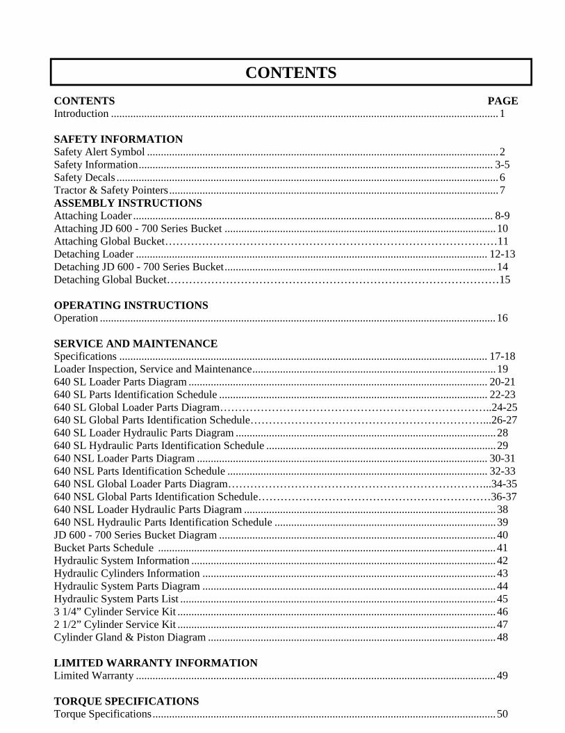
CONTENTS PAGE Introduction ............................................................................................................................................ 1 SAFETY INFORMATION Safety Alert Symbol ............................................................................................................................... 2 Safety Information ................................................................................................................................ 3-5 Safety Decals .......................................................................................................................................... 6 Tractor & Safety Pointers ....................................................................................................................... 7 ASSEMBLY INSTRUCTIONS Attaching Loader .................................................................................................................................. 8-9 Attaching JD 600 - 700 Series Bucket .................................................................................................. 10 Attaching Global Bucket………………………………………………………………………………11 Detaching Loader ............................................................................................................................... 12-13 Detaching JD 600 - 700 Series Bucket .................................................................................................. 14 Detaching Global Bucket………………………………………………………………………………15 OPERATING INSTRUCTIONS Operation ............................................................................................................................................... 16 SERVICE AND MAINTENANCE Specifications ..................................................................................................................................... 17-18 Loader Inspection, Service and Maintenance ........................................................................................ 19 640 SL Loader Parts Diagram ............................................................................................................ 20-21 640 SL Parts Identification Schedule ................................................................................................. 22-23 640 SL Global Loader Parts Diagram………………………………………………………………..24-25 640 SL Global Parts Identification Schedule………………………………………………………...26-27 640 SL Loader Hydraulic Parts Diagram .............................................................................................. 28 640 SL Hydraulic Parts Identification Schedule ................................................................................... 29 640 NSL Loader Parts Diagram ......................................................................................................... 30-31 640 NSL Parts Identification Schedule .............................................................................................. 32-33 640 NSL Global Loader Parts Diagram……………………………………………………………...34-35 640 NSL Global Parts Identification Schedule………………………………………………………36-37 640 NSL Loader Hydraulic Parts Diagram ........................................................................................... 38 640 NSL Hydraulic Parts Identification Schedule ................................................................................ 39 JD 600 - 700 Series Bucket Diagram .................................................................................................... 40 Bucket Parts Schedule .......................................................................................................................... 41 Hydraulic System Information .............................................................................................................. 42 Hydraulic Cylinders Information .......................................................................................................... 43 Hydraulic System Parts Diagram .......................................................................................................... 44 Hydraulic System Parts List .................................................................................................................. 45 3 1/4” Cylinder Service Kit ................................................................................................................... 46 2 1/2” Cylinder Service Kit ................................................................................................................... 47 Cylinder Gland & Piston Diagram ........................................................................................................ 48 LIMITED WARRANTY INFORMATION Limited Warranty .................................................................................................................................. 49 TORQUE SPECIFICATIONS Torque Specifications ............................................................................................................................ 50
INTRODUCTION
TO THE PURCHASER You have purchased an excellent product. With proper care and use, it will give you years of good safe service. Use only LEGEND EQUIPMENT approved parts in the general maintenance and repair of your equipment. Please fill out ownership registration card as soon as possible. Should you have any questions regarding operation of your new LEGEND loader please contact a LEGEND EQUIPMENT company sales representative at 1-855-534-3784 or refer to our company website www.legendequip.com. We care about your safety! Remember ALL safety decals are no charge from the factory. Please replace all safety decals if missing or damaged. Your safety is important to us.
Page 1
SAFETY ALERT SYMBOL
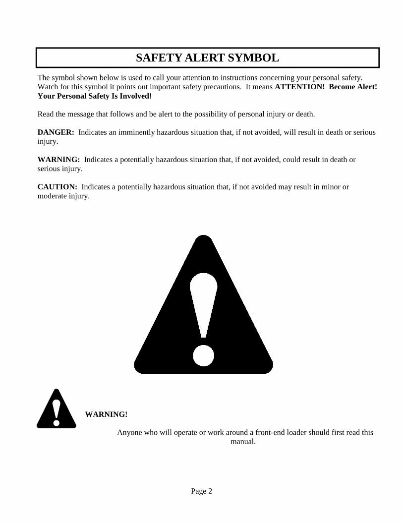
The symbol shown below is used to call your attention to instructions concerning your personal safety. Watch for this symbol it points out important safety precautions. It means ATTENTION! Become Alert! Your Personal Safety Is Involved! Read the message that follows and be alert to the possibility of personal injury or death. DANGER: Indicates an imminently hazardous situation that, if not avoided, will result in death or serious injury. WARNING: Indicates a potentially hazardous situation that, if not avoided, could result in death or serious injury. CAUTION: Indicates a potentially hazardous situation that, if not avoided may result in minor or moderate injury.
WARNING!
Anyone who will operate or work around a front-end loader should first read this manual.
Page 2
SAFETY INFORMATION - (continued)
Improper use of a loader can cause serious injury or death. The following safety precautions, and those given on the tractor mount installation instructions should be thoroughly understood before attempting to operate this machine. BEFORE OPERATING: Carefully study and understand this manual, the specific tractor mount instructions, and the attachment(s) manual(s). Prior to operation, inspect the loader for system leaks and damaged, missing, or malfunctioning components in an effort to avoid the possibility of a dangerous failure involving structural members or hydraulic system components. Be certain any repairs necessary are completed prior to loader operation. Follow recommended loader inspection, service and maintenance on Page 17. Completely familiarize yourself and others involved with the operation of the hydraulic control valve before operating the loader. Be certain all bystanders are clear of the machine and operation area prior to operation. It may be necessary to add wheel ballast or rear weights as recommended by the tractor manufacturer to maintain stability of the machine to prevent tipping or upset which could result in serious injury or death. See mounting instructions for specific information. It is recommended that both front and rear wheel treads be set to the widest recommended width to prevent tipping or upset which could result in serious injury or death. This loader is designed for farm type operations such as snow removal, barn and feedlot cleaning, light commercial or light grading and digging. It’s design is NOT intended for industrial use. DURING OPERATION: Never operate the machine other than from the tractor operator’s seat. Be sure operating area is clear of others during machine operations. Never lift, hoist, or carry humans in the bucket or on any portion of the loader or loader attachments. Failure to heed, may result in serious injury or death.
Page 3

SAFETY INFORMATION – (continued)
Transport the machine load at the slowest speed possible and with the loader boom at the lowest transport position to avoid tipping or upsetting, which may result in serious injury or death. Be extremely careful when working on inclines or near loose fill, rocks, and holes as they can cause tipping or upsetting which may result in serious injury or death. Be certain to avoid overhead electrical wires when operating loader. Contact with power lines may cause serious injury or death. Avoid sudden stops when lowering or lifting the loader boom to prevent loss of control over the machine and/or load, which may result in serious injury or death. Use maximum ballast and the widest recommended wheel setting on your tractor when handling large shiftable loads. Never attempt to ram with the bucket at high speed or full tractor power. Sudden impact may result in structural failure and possible serious injury or death. Never adjust or perform maintenance on the loader or tractor with the unit in motion, or without power source locked out. Never get under bucket or lift arms or reach through the lift arms or bucket linkage when the loader is in operation. Inadvertent movement may cause serious injury or death. FOLLOWING OPERATION: Whenever the machine is not in operation, lower the loader boom and set the tractor brakes, disengage drive, shut the engine off, and remove the ignition key before dismounting the tractor. If loader is to be disengaged from tractor, be sure the loader is securely supported on a hard, level surface and the stand is securely engaged. Be certain all connections between tractor and loader are free before disengaging. TRANSPORTING: Use safety lights and SMV emblem in addition to whatever local codes require when equipment is being transported on the road or highway. Check with proper authorities for legal limitations. Transport all loads at a slow and safe speed. Carry the load as low as possible and maintain adequate visibility and good round clearance at all times.
Page 4
SAFETY INFORMATION - (continued)
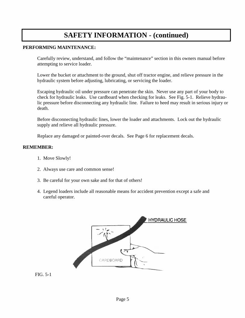
PERFORMING MAINTENANCE: Carefully review, understand, and follow the “maintenance” section in this owners manual before attempting to service loader. Lower the bucket or attachment to the ground, shut off tractor engine, and relieve pressure in the hydraulic system before adjusting, lubricating, or servicing the loader. Escaping hydraulic oil under pressure can penetrate the skin. Never use any part of your body to check for hydraulic leaks. Use cardboard when checking for leaks. See Fig. 5-1. Relieve hydrau- lic pressure before disconnecting any hydraulic line. Failure to heed may result in serious injury or death. Before disconnecting hydraulic lines, lower the loader and attachments. Lock out the hydraulic supply and relieve all hydraulic pressure. Replace any damaged or painted-over decals. See Page 6 for replacement decals. REMEMBER: 1. Move Slowly! 2. Always use care and common sense! 3. Be careful for your own sake and for that of others! 4. Legend loaders include all reasonable means for accident prevention except a safe and careful operator.
FIG. 5-1
Page 5
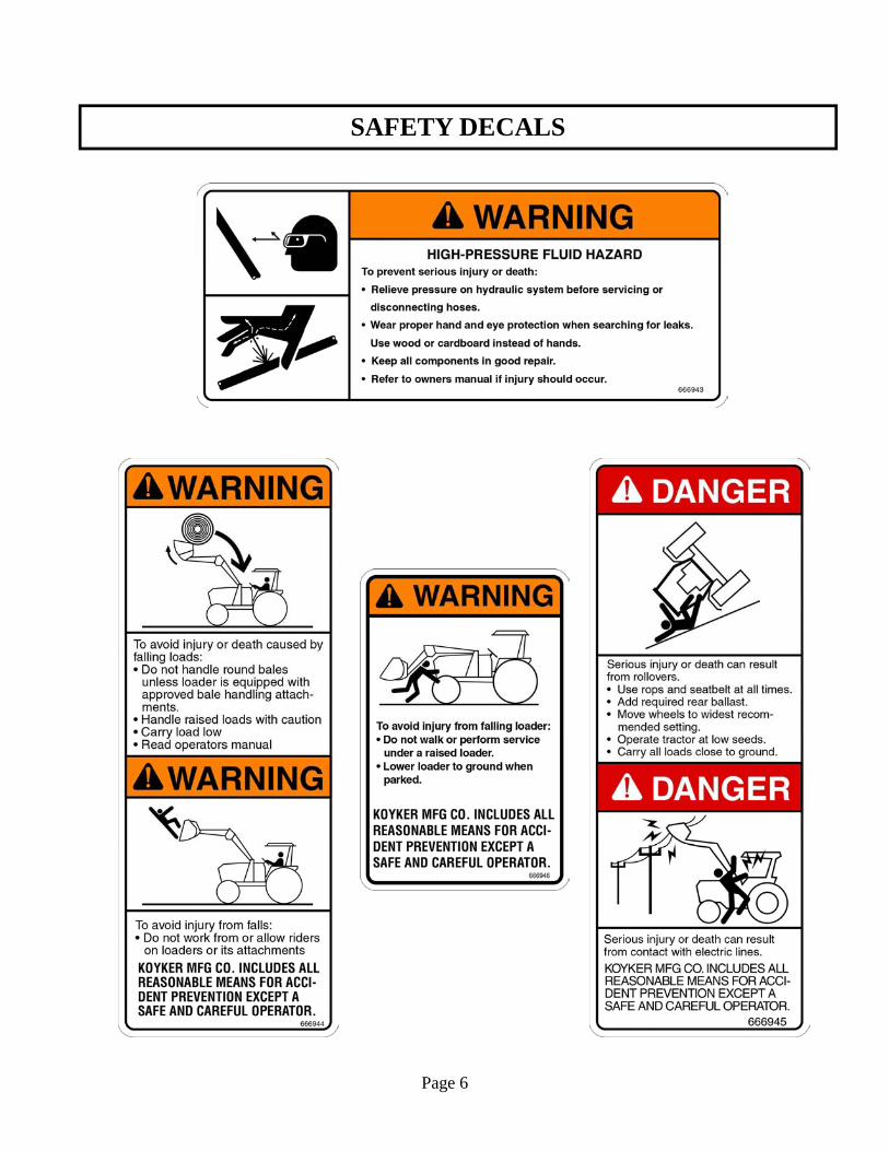
SAFETY DECALS
Page 6
The use of good judgment and common sense is necessary by the operator in using this loader. The front and rear wheels should be set for the widest wheel tread to assure best stability. Use extra caution when rear wheel weights and tire ballast are added to a loader-equipped tractor. DO NOT ram into frozen dirt piles, frozen manure piles, ice, etc., with great momentum where sudden shock loads are encountered. Serious and costly damage may result to both the loader and the tractor. When scraping or back dragging do not extend the attachment cylinders more than one half of the cylinder’s stroke. A limited amount of leveling may be done, when the loader valving is arranged with a float control. This will prevent damage to cylinder rods. Never ride in the bucket. Before operating the loader, be sure no one is standing near it. Only one person, the operator, should be on the tractor. Remain at the controls and under no circumstances leave the tractor unattended with the bucket in a raised position. Never lift a person in the bucket or walk under a raised bucket. Never drive your loader-equipped tractor down a hill that is steeper than 15 degrees. Carry all loads low and use care on side hills. Always keep unused PTO shaft clutch levers disengaged. Keep hands, feet, and clothing away from all moving parts. Hydraulic oil, under pressure, can cause injury. Be sure that all connections are tight and that all pressure is relieved before disconnecting any lines. Care must be taken with your loader cylinders. Nicks, scratches, rust, or other shaft damage can result in worn packing causing cylinder leakage and subnormal performance.
MOVE SLOWLY
USE COMMON SENSE
BE CAREFUL FOR YOUR OWN SAKE AND THAT OF OTHER PEOPLE
TRACTOR & SAFETY POINTERS
Page 7
ATTACHING LOADER
IMPORTANT: Never attempt to attach loader on grades which are not reasonably level.
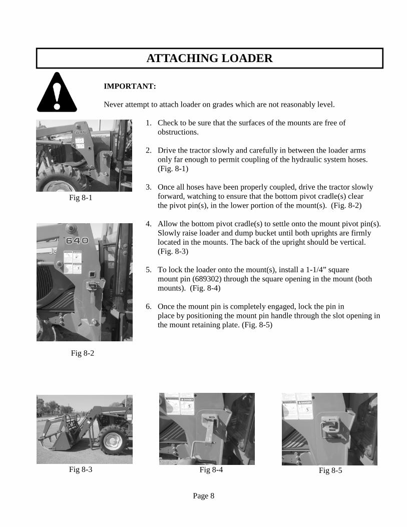
1. Check to be sure that the surfaces of the mounts are free of obstructions. 2. Drive the tractor slowly and carefully in between the loader arms only far enough to permit coupling of the hydraulic system hoses. (Fig. 8-1) 3. Once all hoses have been properly coupled, drive the tractor slowly forward, watching to ensure that the bottom pivot cradle(s) clear
the pivot pin(s), in the lower portion of the mount(s). (Fig. 8-2)
4. Allow the bottom pivot cradle(s) to settle onto the mount pivot pin(s). Slowly raise loader and dump bucket until both uprights are firmly located in the mounts. The back of the upright should be vertical. (Fig. 8-3) 5. To lock the loader onto the mount(s), install a 1-1/4” square mount pin (689302) through the square opening in the mount (both mounts). (Fig. 8-4) 6. Once the mount pin is completely engaged, lock the pin in place by positioning the mount pin handle through the slot opening in the mount retaining plate. (Fig. 8-5)
Page 8
Fig 8-1
Fig 8-4 Fig 8-5 Fig 8-3
Fig 8-2
ATTACHING LOADER (continued)
IMPORTANT: Never attempt to attach loader on grades which are not reasonably level.
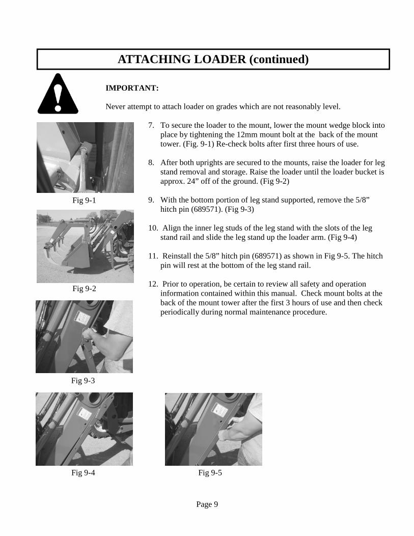
7. To secure the loader to the mount, lower the mount wedge block into place by tightening the 12mm mount bolt at the back of the mount tower. (Fig. 9-1) Re-check bolts after first three hours of use. 8. After both uprights are secured to the mounts, raise the loader for leg stand removal and storage. Raise the loader until the loader bucket is approx. 24” off of the ground. (Fig 9-2)
9. With the bottom portion of leg stand supported, remove the 5/8” hitch pin (689571). (Fig 9-3) 10. Align the inner leg studs of the leg stand with the slots of the leg stand rail and slide the leg stand up the loader arm. (Fig 9-4) 11. Reinstall the 5/8” hitch pin (689571) as shown in Fig 9-5. The hitch pin will rest at the bottom of the leg stand rail. 12. Prior to operation, be certain to review all safety and operation
information contained within this manual. Check mount bolts at the back of the mount tower after the first 3 hours of use and then check periodically during normal maintenance procedure.
Page 9
Fig 9-1
Fig 9-4 Fig 9-5
Fig 9-3
Fig 9-2
ATTACHING JD 600 - 700 SERIES BUCKET
Page 10
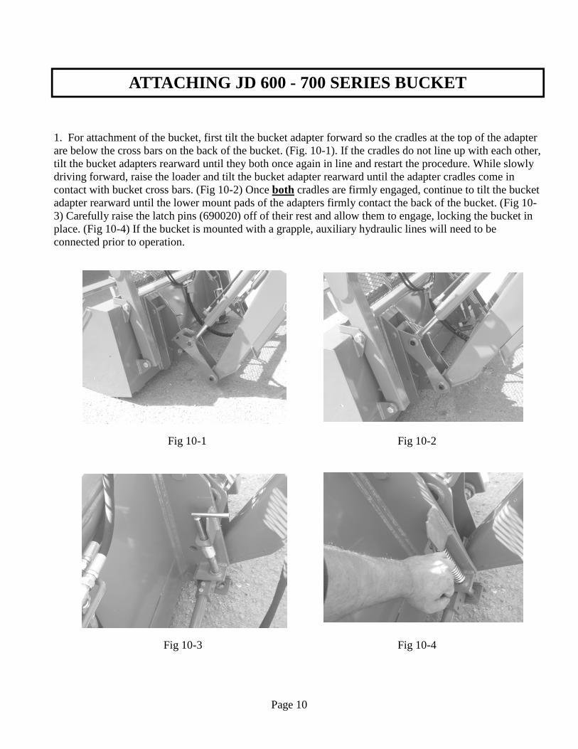
1. For attachment of the bucket, first tilt the bucket adapter forward so the cradles at the top of the adapter are below the cross bars on the back of the bucket. (Fig. 10-1). If the cradles do not line up with each other, tilt the bucket adapters rearward until they both once again in line and restart the procedure. While slowly driving forward, raise the loader and tilt the bucket adapter rearward until the adapter cradles come in contact with bucket cross bars. (Fig 10-2) Once both cradles are firmly engaged, continue to tilt the bucket adapter rearward until the lower mount pads of the adapters firmly contact the back of the bucket. (Fig 10-3) Carefully raise the latch pins (690020) off of their rest and allow them to engage, locking the bucket in place. (Fig 10-4) If the bucket is mounted with a grapple, auxiliary hydraulic lines will need to be connected prior to operation.
Fig 10-3
Fig 10-1 Fig 10-2
Fig 10-4
ATTACHING GLOBAL BUCKET
Page 11
Fig 10-3
Fig 10-1 Fig 10-2
Fig 10-4
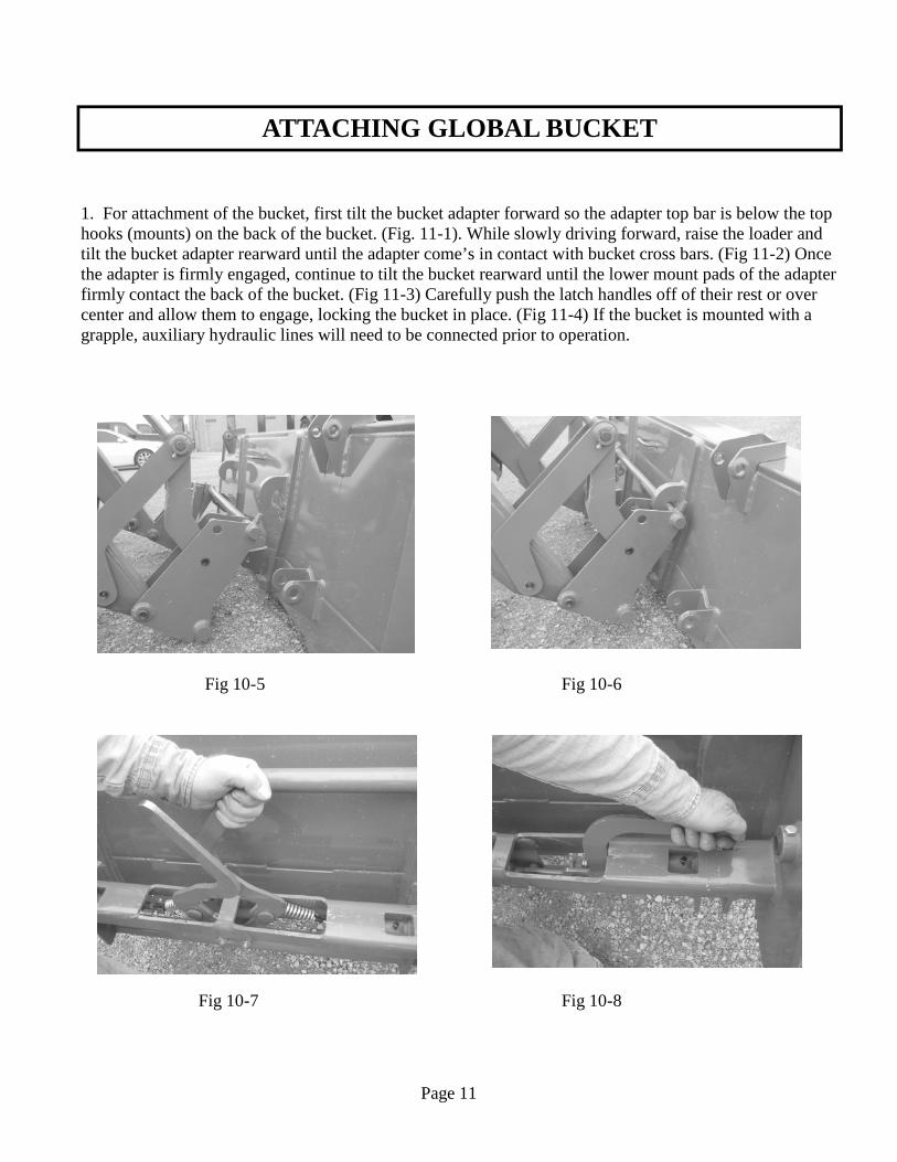
1. For attachment of the bucket, first tilt the bucket adapter forward so the adapter top bar is below the top hooks (mounts) on the back of the bucket. (Fig. 11-1). While slowly driving forward, raise the loader and tilt the bucket adapter rearward until the adapter come’s in contact with bucket cross bars. (Fig 11-2) Once the adapter is firmly engaged, continue to tilt the bucket rearward until the lower mount pads of the adapter firmly contact the back of the bucket. (Fig 11-3) Carefully push the latch handles off of their rest or over center and allow them to engage, locking the bucket in place. (Fig 11-4) If the bucket is mounted with a grapple, auxiliary hydraulic lines will need to be connected prior to operation.
Fig 10-7
Fig 10-5 Fig 10-6
Fig 10-8
DETACHING LOADER
Page 12
IMPORTANT: Never attempt loader detachment on grades which are not reasonably level.
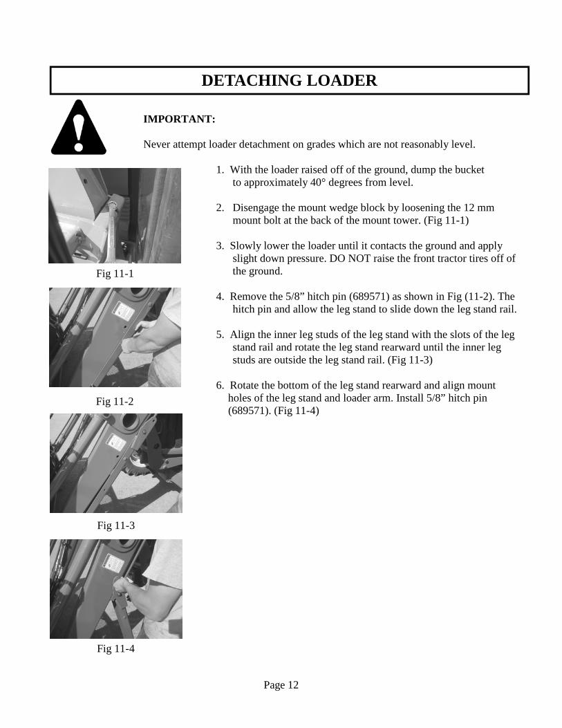
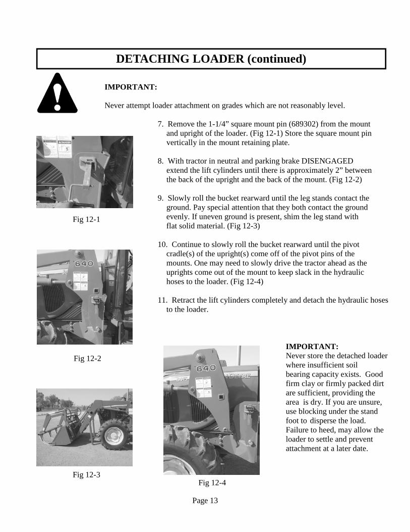
1. With the loader raised off of the ground, dump the bucket to approximately 40° degrees from level. 2. Disengage the mount wedge block by loosening the 12 mm mount bolt at the back of the mount tower. (Fig 11-1) 3. Slowly lower the loader until it contacts the ground and apply slight down pressure. DO NOT raise the front tractor tires off of the ground. 4. Remove the 5/8” hitch pin (689571) as shown in Fig (11-2). The hitch pin and allow the leg stand to slide down the leg stand rail. 5. Align the inner leg studs of the leg stand with the slots of the leg stand rail and rotate the leg stand rearward until the inner leg studs are outside the leg stand rail. (Fig 11-3) 6. Rotate the bottom of the leg stand rearward and align mount
holes of the leg stand and loader arm. Install 5/8” hitch pin (689571). (Fig 11-4)
Fig 11-1
Fig 11-2
Fig 11-3
Fig 11-4
DETACHING LOADER (continued)
Page 13
IMPORTANT: Never attempt loader attachment on grades which are not reasonably level.
7. Remove the 1-1/4” square mount pin (689302) from the mount and upright of the loader. (Fig 12-1) Store the square mount pin vertically in the mount retaining plate. 8. With tractor in neutral and parking brake DISENGAGED extend the lift cylinders until there is approximately 2” between the back of the upright and the back of the mount. (Fig 12-2) 9. Slowly roll the bucket rearward until the leg stands contact the ground. Pay special attention that they both contact the ground
evenly. If uneven ground is present, shim the leg stand with flat solid material. (Fig 12-3)
10. Continue to slowly roll the bucket rearward until the pivot cradle(s) of the upright(s) come off of the pivot pins of the mounts. One may need to slowly drive the tractor ahead as the uprights come out of the mount to keep slack in the hydraulic hoses to the loader. (Fig 12-4) 11. Retract the lift cylinders completely and detach the hydraulic hoses to the loader.
IMPORTANT: Never store the detached loader where insufficient soil bearing capacity exists. Good firm clay or firmly packed dirt are sufficient, providing the area is dry. If you are unsure, use blocking under the stand foot to disperse the load. Failure to heed, may allow the loader to settle and prevent attachment at a later date.
Fig 11-1
Fig 12-1
Fig 12-2
Fig 12-4 Fig 12-3

DETACHING JD 600 - 700 SERIES BUCKET
Page 14
1. If the bucket is mounted with a grapple the auxiliary hydraulic lines need to be disconnected prior to
detachment of the bucket. For detachment of the bucket, first ensure the bucket is resting on flat ground. (Fig 13-1) Disengage the latch pins (690020) and position them onto their rest(s). (Fig 13-2) Slowly lower the loader while tilting the bucket adapters forward. (Fig 13-3) Drive rearward until both adapters have cleared the bucket. (Fig 13-4)
Fig 13-3
Fig 13-1 Fig 13-2
Fig 13-4
DETACHING GLOBAL BUCKET
Page 15
1. If the bucket is mounted with a grapple the auxiliary hydraulic lines need to be disconnected prior to
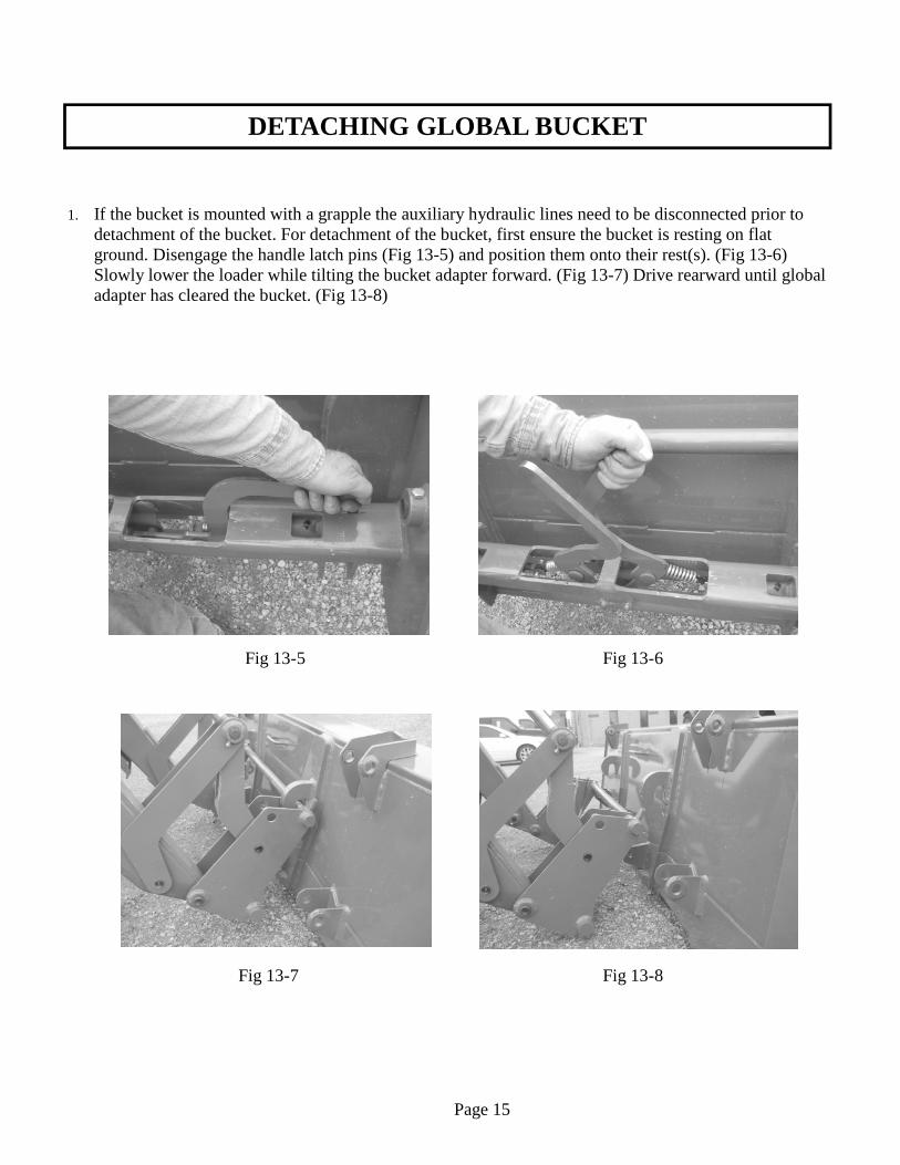
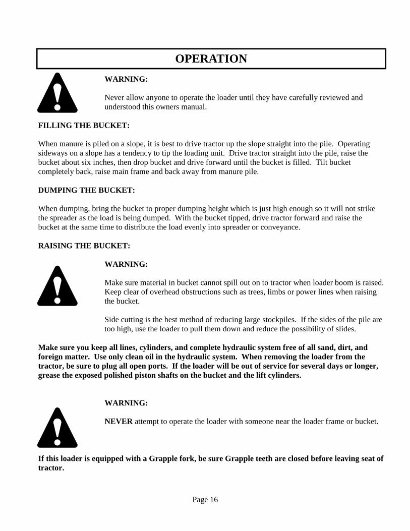
detachment of the bucket. For detachment of the bucket, first ensure the bucket is resting on flat ground. Disengage the handle latch pins (Fig 13-5) and position them onto their rest(s). (Fig 13-6) Slowly lower the loader while tilting the bucket adapter forward. (Fig 13-7) Drive rearward until global adapter has cleared the bucket. (Fig 13-8)
Fig 13-7
Fig 13-5 Fig 13-6
Fig 13-8
Page 15
OPERATION
WARNING: Never allow anyone to operate the loader until they have carefully reviewed and understood this owners manual.
FILLING THE BUCKET: When manure is piled on a slope, it is best to drive tractor up the slope straight into the pile. Operating sideways on a slope has a tendency to tip the loading unit. Drive tractor straight into the pile, raise the bucket about six inches, then drop bucket and drive forward until the bucket is filled. Tilt bucket completely back, raise main frame and back away from manure pile. DUMPING THE BUCKET: When dumping, bring the bucket to proper dumping height which is just high enough so it will not strike the spreader as the load is being dumped. With the bucket tipped, drive tractor forward and raise the bucket at the same time to distribute the load evenly into spreader or conveyance. RAISING THE BUCKET:
WARNING: Make sure material in bucket cannot spill out on to tractor when loader boom is raised. Keep clear of overhead obstructions such as trees, limbs or power lines when raising the bucket.
Side cutting is the best method of reducing large stockpiles. If the sides of the pile are too high, use the loader to pull them down and reduce the possibility of slides. Make sure you keep all lines, cylinders, and complete hydraulic system free of all sand, dirt, and foreign matter. Use only clean oil in the hydraulic system. When removing the loader from the tractor, be sure to plug all open ports. If the loader will be out of service for several days or longer, grease the exposed polished piston shafts on the bucket and the lift cylinders.
WARNING: NEVER attempt to operate the loader with someone near the loader frame or bucket.
If this loader is equipped with a Grapple fork, be sure Grapple teeth are closed before leaving seat of tractor.
Page 16

SPECIFICATIONS
Page 17
Legend 640 SL SPECIFICATIONS Description of Equipment Rated Loader Model ................................................................................................................... 640 SL Lift Cylinder Dia. ......................................................................................................... 3-1/4” Bore Attachment Cylinder Dia. ............................................................................................ 2-1/2” Bore Dimensional Specifications (A) *Maximum Lift Height to Pivot Pin .......................................................................... 12’-2” (B) *Lift Height under Level Bucket ............................................................................... 11’-5” (C) *Clearance with Bucket Dumped @ 45°. ................................................................... 9’- 2” (D) *Reach at Maximum Lift Height ................................................................................. N/A (E) Maximum Dump Angle ................................................................................................ 80° (F) *Reach with Bucket on Ground .................................................................................. 8’-2” (G) Maximum Rollback Angle ........................................................................................... 38° (H) *Digging Depth ............................................................................................................. 7” (J) *Overall Height in Carry Position ............................................................................... 6’-3” Operational Specifications (U) *Lift Capacity to Maximum Height at Pivot Pin .................................................... 3410 lbs. (V) *Lift Capacity to Maximum Height 31.5” Forward of Pivot Pin ............................. N/A lbs. (Y) *Breakout Force at Ground Line at Pivot Pin ......................................................... 5890 lbs. (Z) *Breakout Force at Ground Line 31.5” Forward of Pivot Pin .................................. N/A lbs. *Specifications based on ASABE standards S301.3 (Front-End Agricultural Loader Ratings) Variations in maximum lift height and other specs for different tractors are due to tire sizes, variations in loader mounting locations and hydraulic system efficiency. Specifications are subject to change without notice and without liability therefore.
SPECIFICATIONS
Page 18
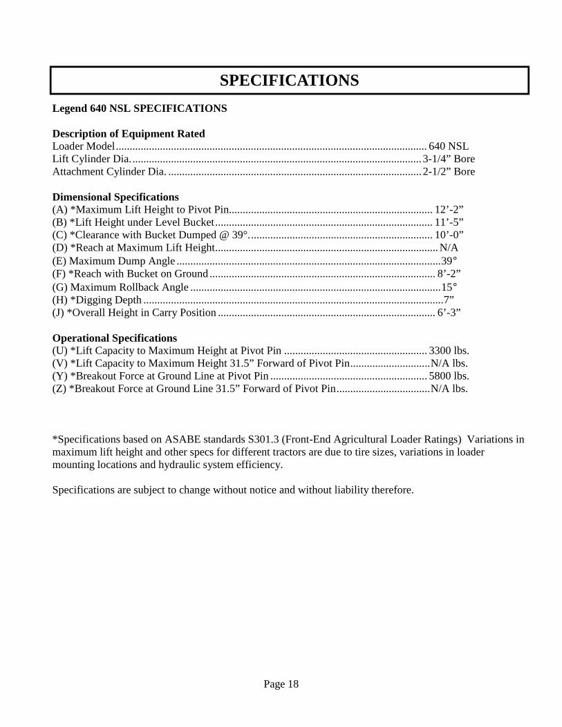
Legend 640 NSL SPECIFICATIONS Description of Equipment Rated Loader Model ................................................................................................................. 640 NSL Lift Cylinder Dia. ......................................................................................................... 3-1/4” Bore Attachment Cylinder Dia. ............................................................................................ 2-1/2” Bore Dimensional Specifications (A) *Maximum Lift Height to Pivot Pin .......................................................................... 12’-2” (B) *Lift Height under Level Bucket ............................................................................... 11’-5” (C) *Clearance with Bucket Dumped @ 39°. .................................................................. 10’-0” (D) *Reach at Maximum Lift Height ................................................................................. N/A (E) Maximum Dump Angle ................................................................................................ 39° (F) *Reach with Bucket on Ground .................................................................................. 8’-2” (G) Maximum Rollback Angle ........................................................................................... 15° (H) *Digging Depth ............................................................................................................. 7” (J) *Overall Height in Carry Position ............................................................................... 6’-3” Operational Specifications (U) *Lift Capacity to Maximum Height at Pivot Pin .................................................... 3300 lbs. (V) *Lift Capacity to Maximum Height 31.5” Forward of Pivot Pin ............................. N/A lbs. (Y) *Breakout Force at Ground Line at Pivot Pin ......................................................... 5800 lbs. (Z) *Breakout Force at Ground Line 31.5” Forward of Pivot Pin .................................. N/A lbs. *Specifications based on ASABE standards S301.3 (Front-End Agricultural Loader Ratings) Variations in maximum lift height and other specs for different tractors are due to tire sizes, variations in loader mounting locations and hydraulic system efficiency. Specifications are subject to change without notice and without liability therefore.
LOADER INSPECTION, SERVICE AND MAINTENANCE
Lower the bucket to the ground, shut off tractor engine and relieve the pressure in the hydraulic system before adjusting, lubricating or servicing the loader. Inspect all pins and grease fittings before each use and lubricate with heavy duty grease as indicated in this manual. Periodically check all bolts for looseness and re-torque if necessary. Before storage, be certain all hydraulic cylinders are fully collapsed so that the rod will not be exposed to the elements or damaged. Be certain hydraulic system remains sealed at all times to prevent contamination. Check and maintain an adequate fluid level in the tractor reservoir prior to use. Inspect all hydraulic system hoses and fittings. Replace prior to further operation if damaged.
WARNING!
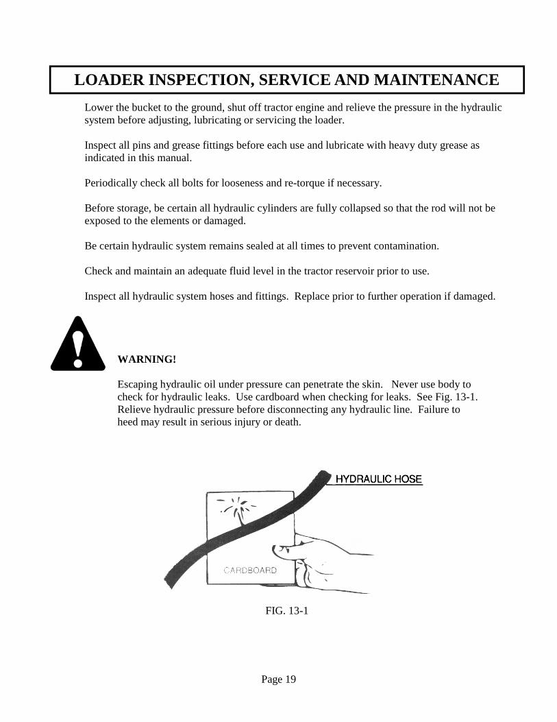
Escaping hydraulic oil under pressure can penetrate the skin. Never use body to check for hydraulic leaks. Use cardboard when checking for leaks. See Fig. 13-1. Relieve hydraulic pressure before disconnecting any hydraulic line. Failure to heed may result in serious injury or death.
FIG. 13-1
Page 19
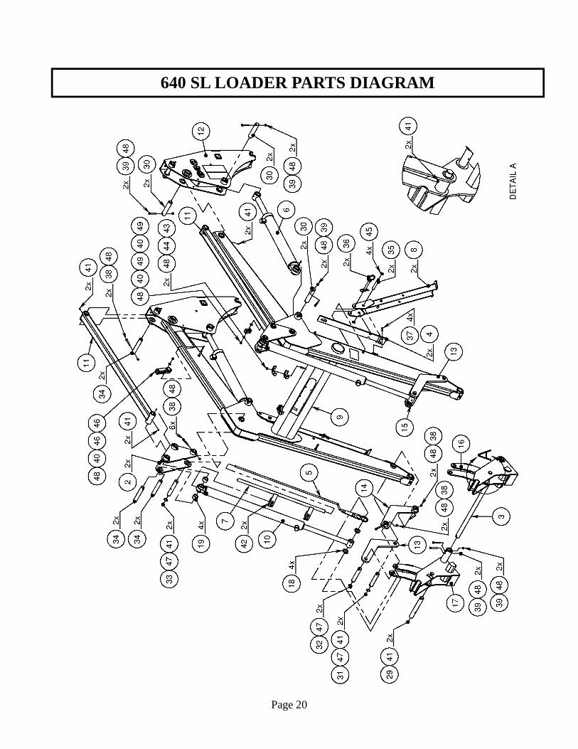
640 SL LOADER PARTS DIAGRAM
Page 20
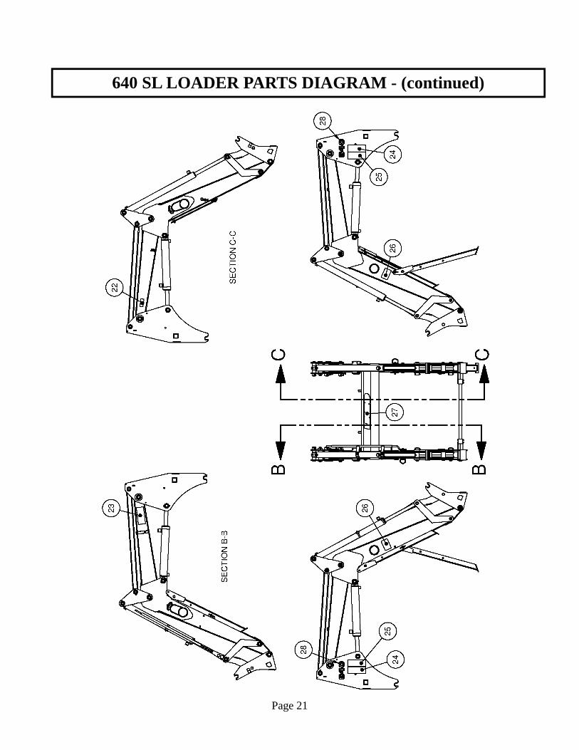
640 SL LOADER PARTS DIAGRAM - (continued)
Page 21
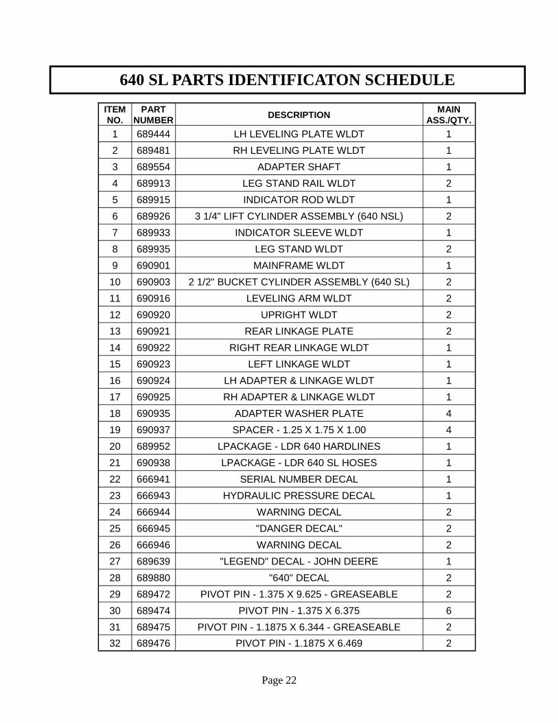
640 SL PARTS IDENTIFICATON SCHEDULE
Page 22
ITEM NO.
PART NUMBER DESCRIPTION
MAIN ASS./QTY.
1 689444 LH LEVELING PLATE WLDT 1
2 689481 RH LEVELING PLATE WLDT 1
3 689554 ADAPTER SHAFT 1
4 689913 LEG STAND RAIL WLDT 2
5 689915 INDICATOR ROD WLDT 1
6 689926 3 1/4" LIFT CYLINDER ASSEMBLY (640 NSL) 2
7 689933 INDICATOR SLEEVE WLDT 1
8 689935 LEG STAND WLDT 2
9 690901 MAINFRAME WLDT 1
10 690903 2 1/2" BUCKET CYLINDER ASSEMBLY (640 SL) 2
11 690916 LEVELING ARM WLDT 2
12 690920 UPRIGHT WLDT 2
13 690921 REAR LINKAGE PLATE 2
14 690922 RIGHT REAR LINKAGE WLDT 1
15 690923 LEFT LINKAGE WLDT 1
16 690924 LH ADAPTER & LINKAGE WLDT 1
17 690925 RH ADAPTER & LINKAGE WLDT 1
18 690935 ADAPTER WASHER PLATE 4
19 690937 SPACER - 1.25 X 1.75 X 1.00 4
20 689952 LPACKAGE - LDR 640 HARDLINES 1
21 690938 LPACKAGE - LDR 640 SL HOSES 1
22 666941 SERIAL NUMBER DECAL 1
23 666943 HYDRAULIC PRESSURE DECAL 1
24 666944 WARNING DECAL 2
25 666945 "DANGER DECAL" 2
26 666946 WARNING DECAL 2
27 689639 "LEGEND" DECAL - JOHN DEERE 1
28 689880 "640" DECAL 2
29 689472 PIVOT PIN - 1.375 X 9.625 - GREASEABLE 2
30 689474 PIVOT PIN - 1.375 X 6.375 6
31 689475 PIVOT PIN - 1.1875 X 6.344 - GREASEABLE 2
32 689476 PIVOT PIN - 1.1875 X 6.469 2
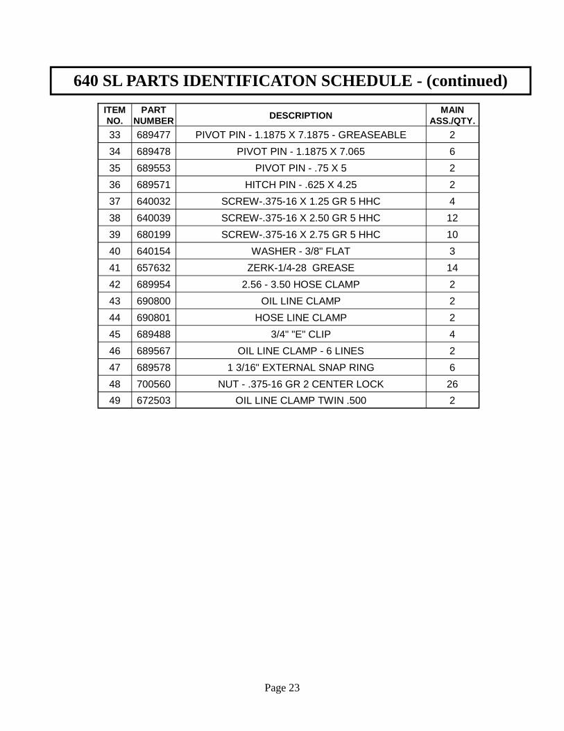
640 SL PARTS IDENTIFICATON SCHEDULE - (continued)
Page 23
ITEM NO.
PART NUMBER DESCRIPTION
MAIN ASS./QTY.
33 689477 PIVOT PIN - 1.1875 X 7.1875 - GREASEABLE 2
34 689478 PIVOT PIN - 1.1875 X 7.065 6
35 689553 PIVOT PIN - .75 X 5 2
36 689571 HITCH PIN - .625 X 4.25 2
37 640032 SCREW-.375-16 X 1.25 GR 5 HHC 4
38 640039 SCREW-.375-16 X 2.50 GR 5 HHC 12
39 680199 SCREW-.375-16 X 2.75 GR 5 HHC 10
40 640154 WASHER - 3/8" FLAT 3
41 657632 ZERK-1/4-28 GREASE 14
42 689954 2.56 - 3.50 HOSE CLAMP 2
43 690800 OIL LINE CLAMP 2
44 690801 HOSE LINE CLAMP 2
45 689488 3/4" "E" CLIP 4
46 689567 OIL LINE CLAMP - 6 LINES 2
47 689578 1 3/16" EXTERNAL SNAP RING 6
48 700560 NUT - .375-16 GR 2 CENTER LOCK 26
49 672503 OIL LINE CLAMP TWIN .500 2
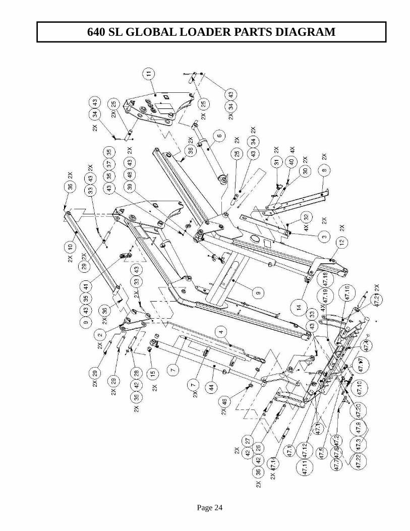
640 SL GLOBAL LOADER PARTS DIAGRAM
Page 24
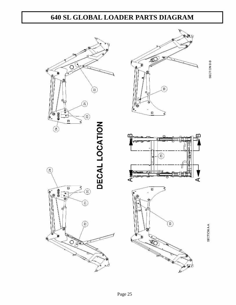
640 SL GLOBAL LOADER PARTS DIAGRAM
Page 25
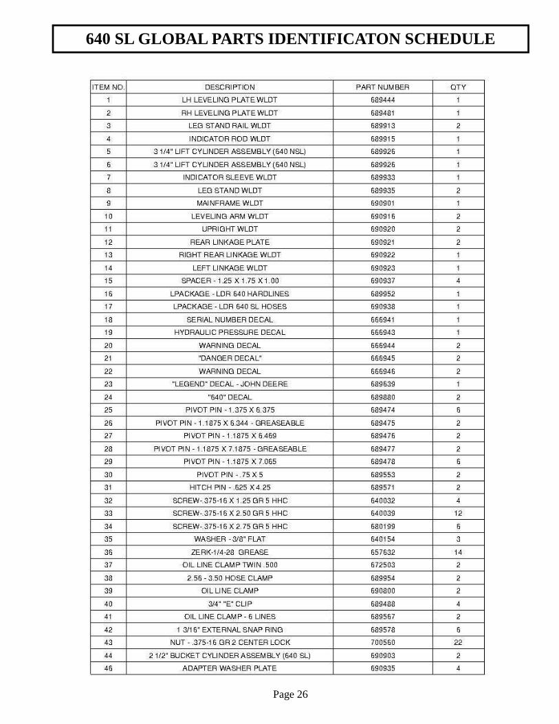
640 SL GLOBAL PARTS IDENTIFICATON SCHEDULE
Page 26
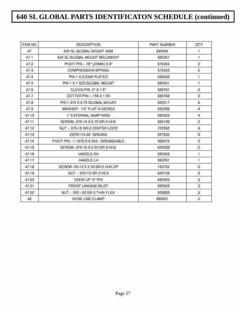
640 SL GLOBAL PARTS IDENTIFICATON SCHEDULE (continued)
Page 27
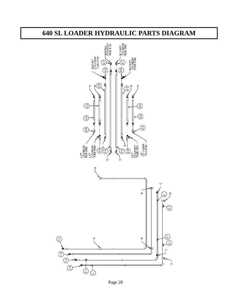
640 SL LOADER HYDRAULIC PARTS DIAGRAM
Page 28
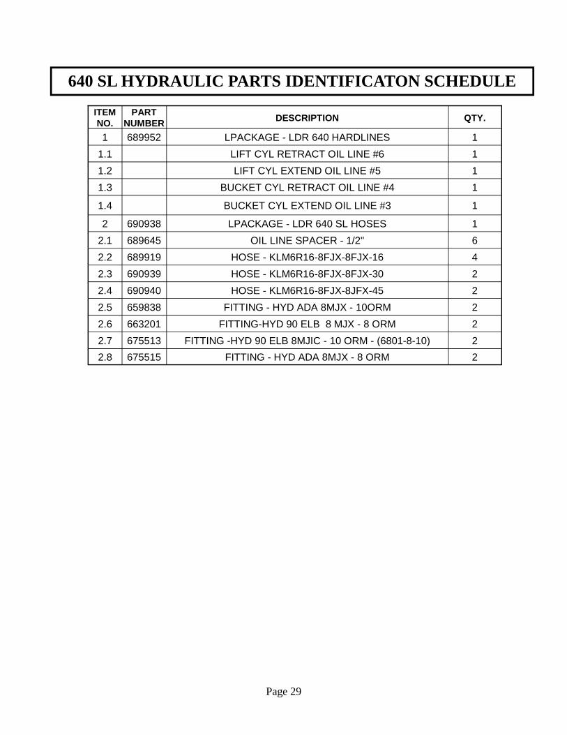
640 SL HYDRAULIC PARTS IDENTIFICATON SCHEDULE
Page 29
ITEM NO.
PART NUMBER DESCRIPTION QTY.
1 689952 LPACKAGE - LDR 640 HARDLINES 1
1.1 LIFT CYL RETRACT OIL LINE #6 1
1.2 LIFT CYL EXTEND OIL LINE #5 1
1.3 BUCKET CYL RETRACT OIL LINE #4 1
1.4 BUCKET CYL EXTEND OIL LINE #3 1
2 690938 LPACKAGE - LDR 640 SL HOSES 1
2.1 689645 OIL LINE SPACER - 1/2" 6
2.2 689919 HOSE - KLM6R16-8FJX-8FJX-16 4
2.3 690939 HOSE - KLM6R16-8FJX-8FJX-30 2
2.4 690940 HOSE - KLM6R16-8FJX-8JFX-45 2
2.5 659838 FITTING - HYD ADA 8MJX - 10ORM 2
2.6 663201 FITTING-HYD 90 ELB 8 MJX - 8 ORM 2
2.7 675513 FITTING -HYD 90 ELB 8MJIC - 10 ORM - (6801-8-10) 2
2.8 675515 FITTING - HYD ADA 8MJX - 8 ORM 2
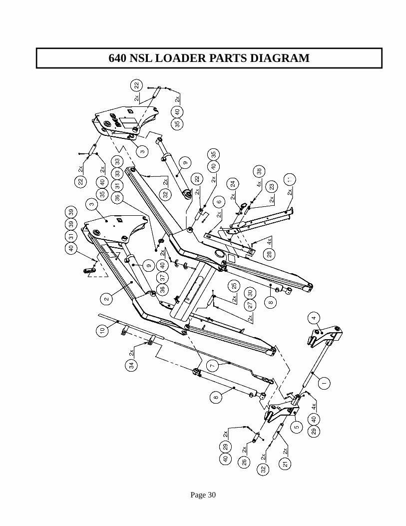
640 NSL LOADER PARTS DIAGRAM
Page 30
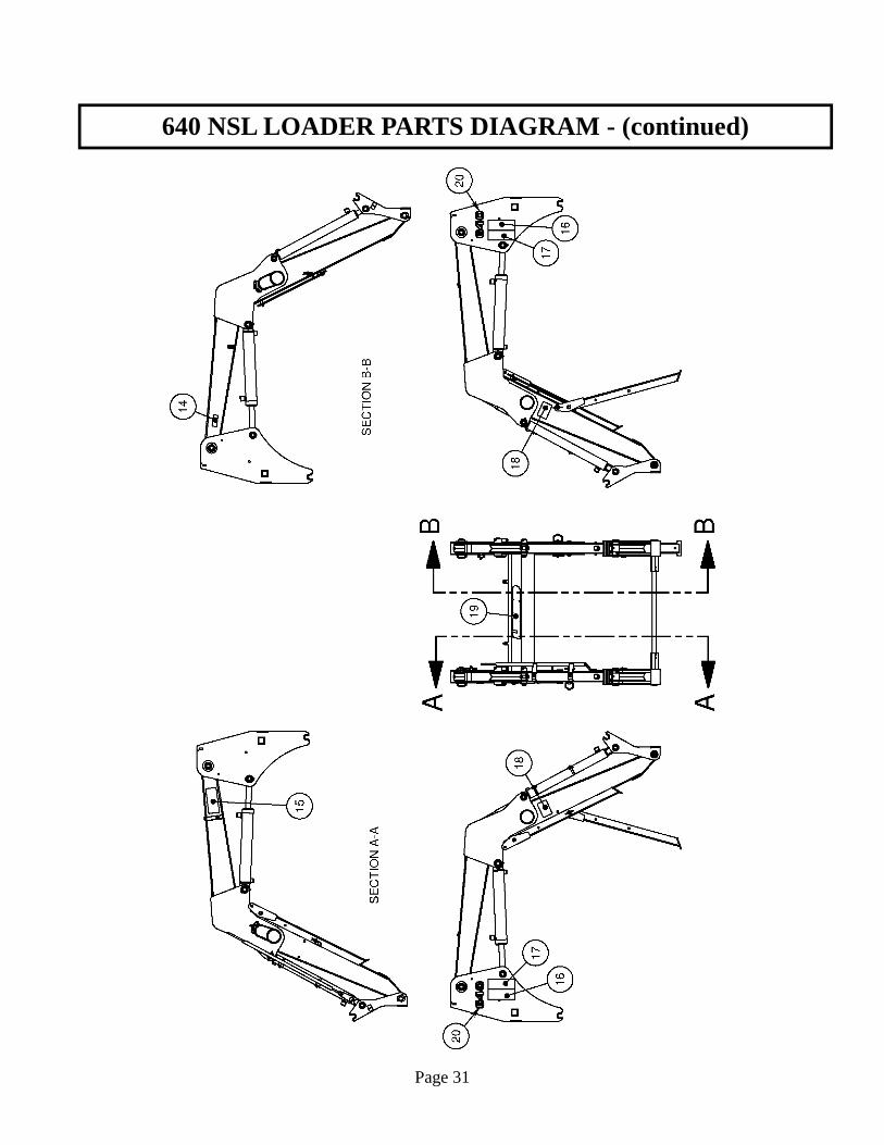
640 NSL LOADER PARTS DIAGRAM - (continued)
Page 31
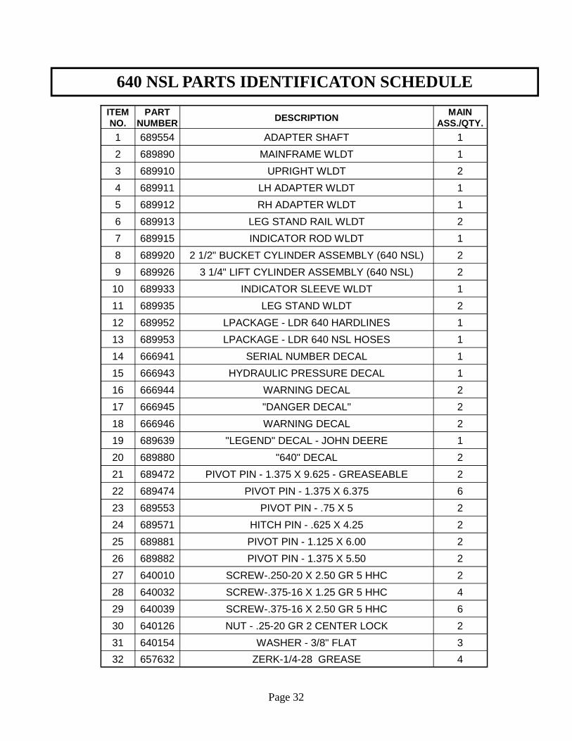
640 NSL PARTS IDENTIFICATON SCHEDULE
Page 32
ITEM NO.
PART NUMBER DESCRIPTION
MAIN ASS./QTY.
1 689554 ADAPTER SHAFT 1
2 689890 MAINFRAME WLDT 1
3 689910 UPRIGHT WLDT 2
4 689911 LH ADAPTER WLDT 1
5 689912 RH ADAPTER WLDT 1
6 689913 LEG STAND RAIL WLDT 2
7 689915 INDICATOR ROD WLDT 1
8 689920 2 1/2" BUCKET CYLINDER ASSEMBLY (640 NSL) 2
9 689926 3 1/4" LIFT CYLINDER ASSEMBLY (640 NSL) 2
10 689933 INDICATOR SLEEVE WLDT 1
11 689935 LEG STAND WLDT 2
12 689952 LPACKAGE - LDR 640 HARDLINES 1
13 689953 LPACKAGE - LDR 640 NSL HOSES 1
14 666941 SERIAL NUMBER DECAL 1
15 666943 HYDRAULIC PRESSURE DECAL 1
16 666944 WARNING DECAL 2
17 666945 "DANGER DECAL" 2
18 666946 WARNING DECAL 2
19 689639 "LEGEND" DECAL - JOHN DEERE 1
20 689880 "640" DECAL 2
21 689472 PIVOT PIN - 1.375 X 9.625 - GREASEABLE 2
22 689474 PIVOT PIN - 1.375 X 6.375 6
23 689553 PIVOT PIN - .75 X 5 2
24 689571 HITCH PIN - .625 X 4.25 2
25 689881 PIVOT PIN - 1.125 X 6.00 2
26 689882 PIVOT PIN - 1.375 X 5.50 2
27 640010 SCREW-.250-20 X 2.50 GR 5 HHC 2
28 640032 SCREW-.375-16 X 1.25 GR 5 HHC 4
29 640039 SCREW-.375-16 X 2.50 GR 5 HHC 6
30 640126 NUT - .25-20 GR 2 CENTER LOCK 2
31 640154 WASHER - 3/8" FLAT 3
32 657632 ZERK-1/4-28 GREASE 4
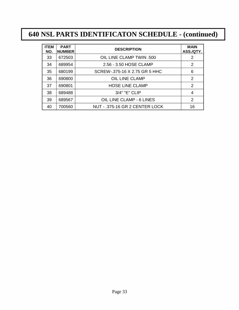
640 NSL PARTS IDENTIFICATON SCHEDULE - (continued)
Page 33
ITEM NO.
PART NUMBER DESCRIPTION
MAIN ASS./QTY.
33 672503 OIL LINE CLAMP TWIN .500 2
34 689954 2.56 - 3.50 HOSE CLAMP 2
35 680199 SCREW-.375-16 X 2.75 GR 5 HHC 6
36 690800 OIL LINE CLAMP 2
37 690801 HOSE LINE CLAMP 2
38 689488 3/4" "E" CLIP 4
39 689567 OIL LINE CLAMP - 6 LINES 2
40 700560 NUT - .375-16 GR 2 CENTER LOCK 16
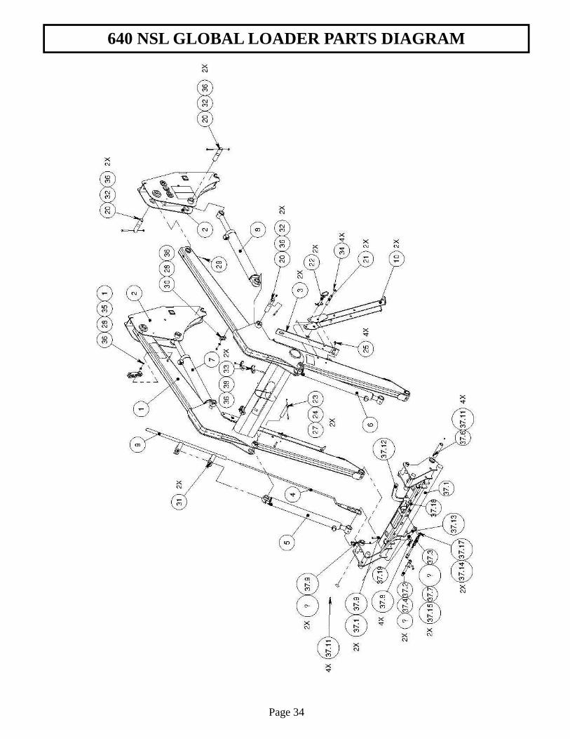
640 NSL GLOBAL LOADER PARTS DIAGRAM
Page 34
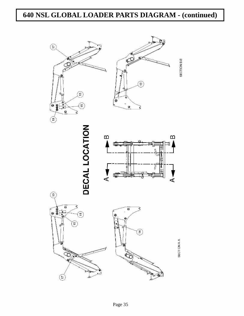
640 NSL GLOBAL LOADER PARTS DIAGRAM - (continued)
Page 35
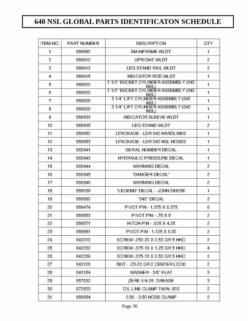
640 NSL GLOBAL PARTS IDENTIFICATON SCHEDULE
Page 36
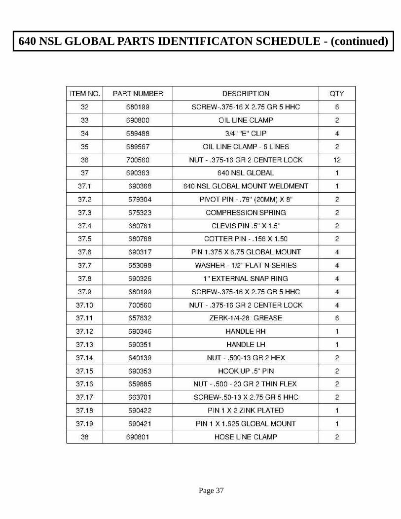
640 NSL GLOBAL PARTS IDENTIFICATON SCHEDULE - (continued)
Page 37
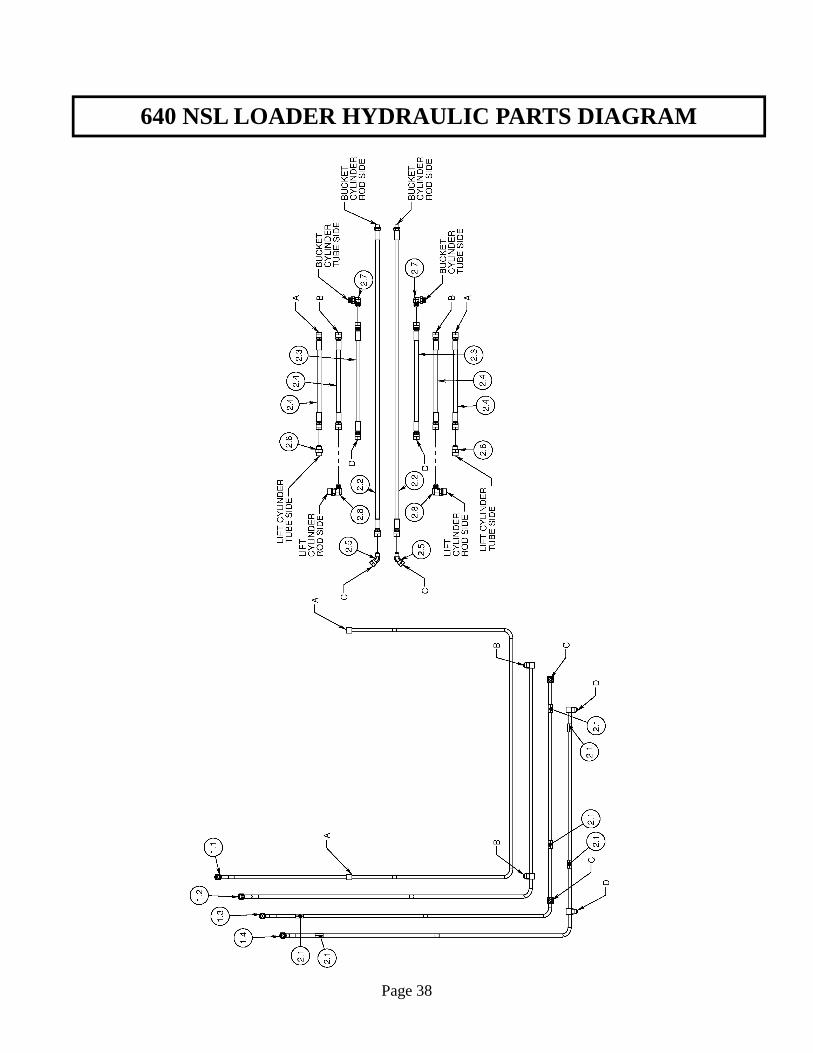
640 NSL LOADER HYDRAULIC PARTS DIAGRAM
Page 38
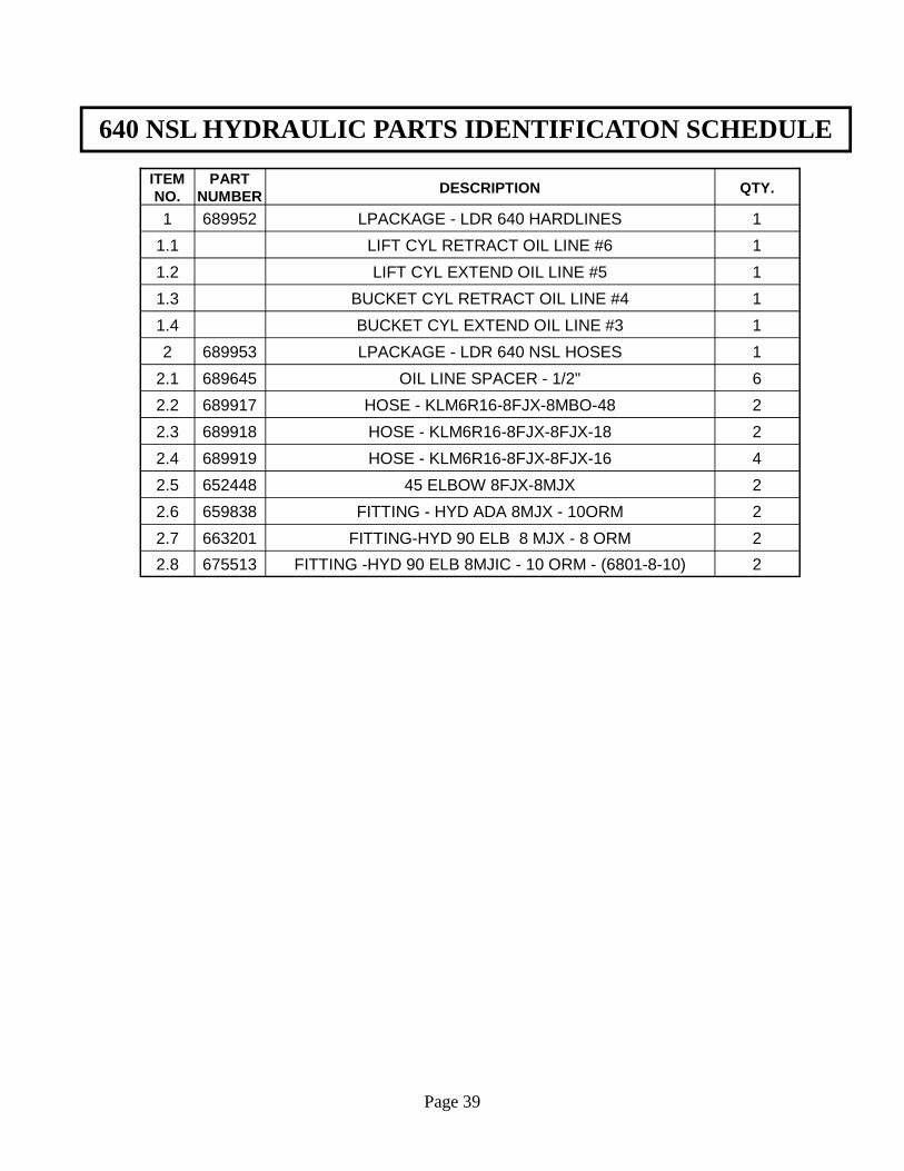
640 NSL HYDRAULIC PARTS IDENTIFICATON SCHEDULE
Page 39
ITEM NO.
PART NUMBER DESCRIPTION QTY.
1 689952 LPACKAGE - LDR 640 HARDLINES 1
1.1 LIFT CYL RETRACT OIL LINE #6 1
1.2 LIFT CYL EXTEND OIL LINE #5 1
1.3 BUCKET CYL RETRACT OIL LINE #4 1
1.4 BUCKET CYL EXTEND OIL LINE #3 1
2 689953 LPACKAGE - LDR 640 NSL HOSES 1
2.1 689645 OIL LINE SPACER - 1/2" 6
2.2 689917 HOSE - KLM6R16-8FJX-8MBO-48 2
2.3 689918 HOSE - KLM6R16-8FJX-8FJX-18 2
2.4 689919 HOSE - KLM6R16-8FJX-8FJX-16 4
2.5 652448 45 ELBOW 8FJX-8MJX 2
2.6 659838 FITTING - HYD ADA 8MJX - 10ORM 2
2.7 663201 FITTING-HYD 90 ELB 8 MJX - 8 ORM 2
2.8 675513 FITTING -HYD 90 ELB 8MJIC - 10 ORM - (6801-8-10) 2
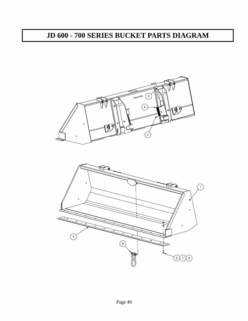
JD 600 - 700 SERIES BUCKET PARTS DIAGRAM
Page 40
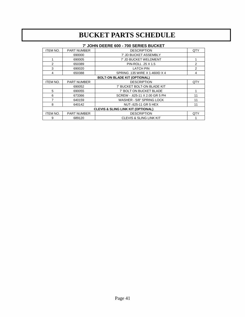
BUCKET PARTS SCHEDULE
Page 41
7' JOHN DEERE 600 - 700 SERIES BUCKET ITEM NO. PART NUMBER DESCRIPTION QTY
690000 7' JD BUCKET ASSEMBLY 1 690005 7' JD BUCKET WELDMENT 1 2 650389 PIN-ROLL .25 X 1.5 2 3 690020 LATCH PIN 2 4 650388 SPRING .135 WIRE X 1.460ID X 4 4
BOLT-ON BLADE KIT (OPTIONAL) ITEM NO. PART NUMBER DESCRIPTION QTY
690052 7’ BUCKET BOLT-ON BLADE KIT 5 690055 7’ BOLT ON BUCKET BLADE 1 6 673366 SCREW - .625-11 X 2.00 GR 5 PH 11 7 640159 WASHER - 5/8" SPRING LOCK 11 8 640142 NUT-.625-11 GR 5 HEX 11
CLEVIS & SLING LINK KIT (OPTIONAL) ITEM NO. PART NUMBER DESCRIPTION QTY
9 689120 CLEVIS & SLING LINK KIT 1
HYDRAULIC SYSTEM INFORMATION
The hoses from the tractor valves are attached to the oil lines which are on the inside of the loader main frame. Re-check all joints to prevent leakage after loader is mounted and in operation. KEEP SYSTEM CLEAN - USE ONLY CLEAN OIL
CAUTION! It is of utmost importance that the hydraulic system of this loader be kept free from dirt and foreign matter.
All internal parts to the hydraulic system of your loader have been carefully cleaned, inspected, and plugged with protective caps before shipment. All protective caps should be kept in place until the hydraulic system is connected. NOTE: Over 75 percent of all hydraulic failure and service is caused by dirt, etc. in the system.
REMEMBER - CLEAN OIL MEANS LONGER LIFE!
Page 42
HYDRAULIC CYLINDERS INFORMATION
IMPORTANT: Read these service tips before beginning assembly of cylinder gland or piston. 1. Keep seals clean from the time they are removed from package until they are installed. 2. Clean the groove or bore into which the seal is to be fitted before installing the seal. 3. Never touch the seal lip in handling. Always pick up the seal by its outer member. 4. Inspect each seal lip carefully for nicks, scratches, and dirt at time of installation. If dirty use a soft, clean cloth and carefully wipe off seal. DO NOT wipe seal with fingers, this only imbeds dirt in the seal.
NEVER clean rubber related seals with a mineral based solvent! Clean rubber seals in denatured alcohol or non-mineral based solvents only.
NOTE: Seals can be made more pliable and easier to install, if first heated in hydraulic oil to 160°F. Never use direct heat on any seals.
Page 43
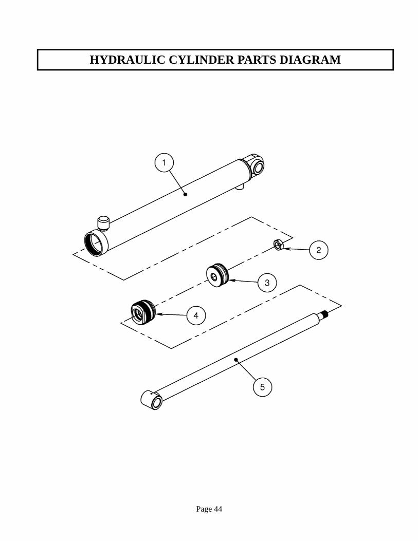
HYDRAULIC CYLINDER PARTS DIAGRAM
Page 44
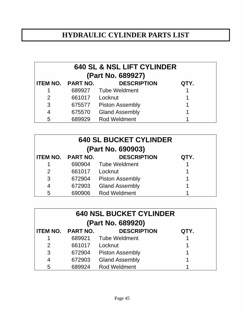
HYDRAULIC CYLINDER PARTS LIST
Page 45
640 SL & NSL LIFT CYLINDER (Part No. 689927)
ITEM NO. PART NO. DESCRIPTION QTY.
1 689927 Tube Weldment 1
2 661017 Locknut 1
3 675577 Piston Assembly 1
4 675570 Gland Assembly 1
5 689929 Rod Weldment 1
640 SL BUCKET CYLINDER (Part No. 690903)
ITEM NO. PART NO. DESCRIPTION QTY.
1 690904 Tube Weldment 1
2 661017 Locknut 1
3 672904 Piston Assembly 1
4 672903 Gland Assembly 1
5 690906 Rod Weldment 1
640 NSL BUCKET CYLINDER (Part No. 689920)
ITEM NO. PART NO. DESCRIPTION QTY.
1 689921 Tube Weldment 1
2 661017 Locknut 1
3 672904 Piston Assembly 1
4 672903 Gland Assembly 1
5 689924 Rod Weldment 1
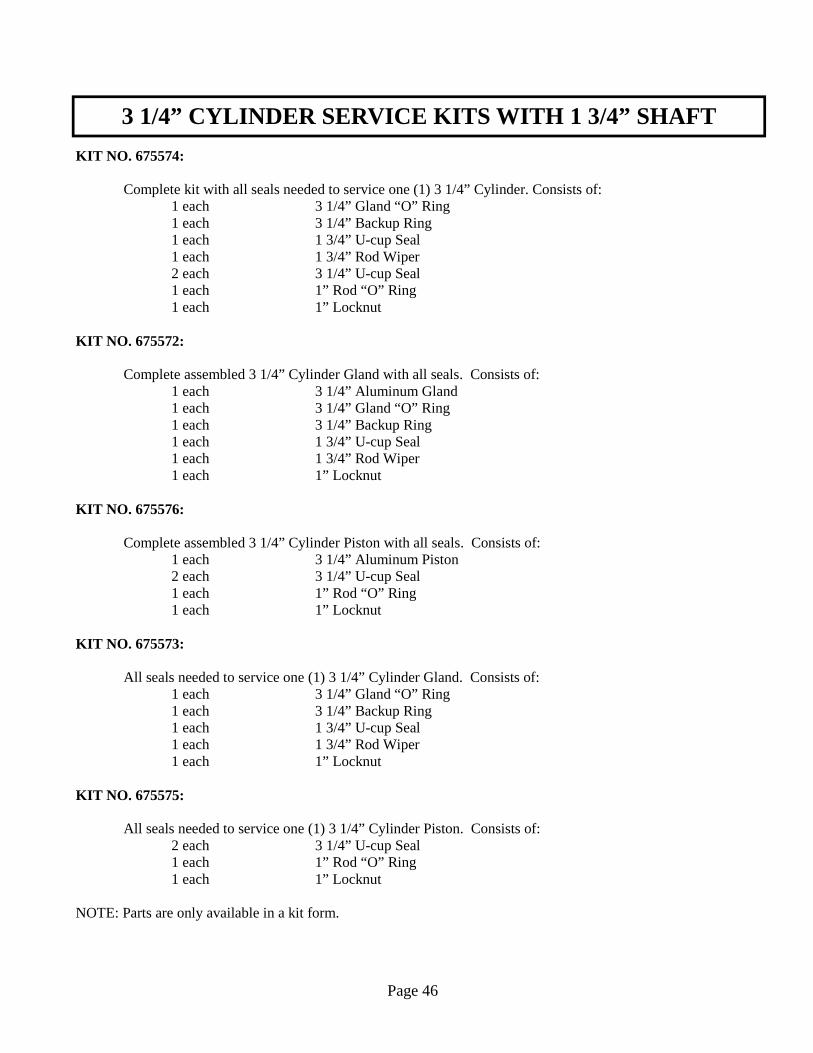
3 1/4” CYLINDER SERVICE KITS WITH 1 3/4” SHAFT
KIT NO. 675574: Complete kit with all seals needed to service one (1) 3 1/4” Cylinder. Consists of: 1 each 3 1/4” Gland “O” Ring 1 each 3 1/4” Backup Ring 1 each 1 3/4” U-cup Seal 1 each 1 3/4” Rod Wiper 2 each 3 1/4” U-cup Seal 1 each 1” Rod “O” Ring 1 each 1” Locknut KIT NO. 675572: Complete assembled 3 1/4” Cylinder Gland with all seals. Consists of: 1 each 3 1/4” Aluminum Gland 1 each 3 1/4” Gland “O” Ring 1 each 3 1/4” Backup Ring 1 each 1 3/4” U-cup Seal 1 each 1 3/4” Rod Wiper 1 each 1” Locknut KIT NO. 675576: Complete assembled 3 1/4” Cylinder Piston with all seals. Consists of: 1 each 3 1/4” Aluminum Piston 2 each 3 1/4” U-cup Seal 1 each 1” Rod “O” Ring 1 each 1” Locknut KIT NO. 675573: All seals needed to service one (1) 3 1/4” Cylinder Gland. Consists of: 1 each 3 1/4” Gland “O” Ring 1 each 3 1/4” Backup Ring 1 each 1 3/4” U-cup Seal 1 each 1 3/4” Rod Wiper 1 each 1” Locknut KIT NO. 675575: All seals needed to service one (1) 3 1/4” Cylinder Piston. Consists of: 2 each 3 1/4” U-cup Seal 1 each 1” Rod “O” Ring 1 each 1” Locknut NOTE: Parts are only available in a kit form.
Page 46

2 1/2” CYLINDER SERVICE KITS WITH 1 1/2” SHAFT
KIT NO. 662048: Complete kit with all seals needed to service one (1) 2 1/2” Cylinder. Consists of: 1 each 2 1/2” Gland “O” Ring 1 each 2 1/2” Backup Ring 1 each 1 1/2” U-cup Seal 1 each 1 1/2” Rod Wiper 2 each 2 1/2” U-cup Seal 1 each 1” Rod “O” Ring 1 each 1” Locknut KIT NO. 663317: Complete assembled 2 1/2” Cylinder Gland with all seals. Consists of: 1 each 2 1/2” Aluminum Gland 1 each 2 1/2” Gland “O” Ring 1 each 2 1/2” Backup Ring 1 each 1 1/2” U-cup Seal 1 each 1 1/2” Rod Wiper 1 each 1” Locknut KIT NO. 663318: Complete assembled 2 1/2” Cylinder Piston with all seals. Consists of: 1 each 2 1/2” Aluminum Piston 2 each 2 1/2” U-cup Seal 1 each 1” Rod “O” Ring 1 each 1” Locknut KIT NO. 662052: All seals needed to service one (1) 2 1/2” Cylinder Gland. Consists of: 1 each 2 1/2” Gland “O” Ring 1 each 2 1/2” Backup Ring 1 each 1 1/2” U-cup Seal 1 each 1 1/2” Rod Wiper 1 each 1” Locknut KIT NO. 662055: All seals needed to service one (1) 2 1/2” Cylinder Piston. Consists of: 2 each 2 1/2” U-cup Seal 1 each 1” Rod “O” Ring 1 each 1” Locknut NOTE: Parts are only available in a kit form.
Page 47
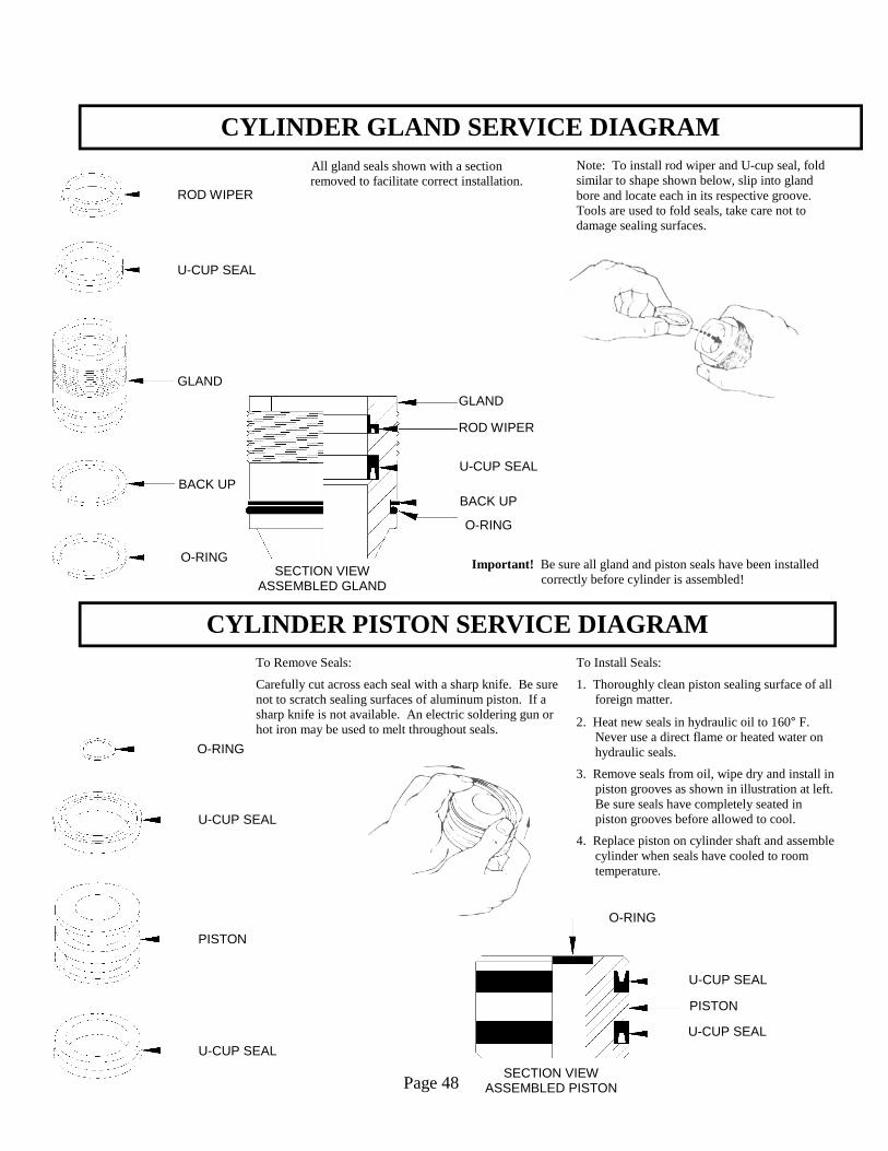
CYLINDER GLAND SERVICE DIAGRAM
CYLINDER PISTON SERVICE DIAGRAM
Page 48
To Install Seals:
1. Thoroughly clean piston sealing surface of all foreign matter.
2. Heat new seals in hydraulic oil to 160° F. Never use a direct flame or heated water on hydraulic seals.
3. Remove seals from oil, wipe dry and install in piston grooves as shown in illustration at left. Be sure seals have completely seated in piston grooves before allowed to cool.
4. Replace piston on cylinder shaft and assemble cylinder when seals have cooled to room temperature.
To Remove Seals:
Carefully cut across each seal with a sharp knife. Be sure not to scratch sealing surfaces of aluminum piston. If a sharp knife is not available. An electric soldering gun or hot iron may be used to melt throughout seals.
All gland seals shown with a section removed to facilitate correct installation.
Note: To install rod wiper and U-cup seal, fold similar to shape shown below, slip into gland bore and locate each in its respective groove. Tools are used to fold seals, take care not to damage sealing surfaces.
Important! Be sure all gland and piston seals have been installed correctly before cylinder is assembled!
O-RING
U-CUP SEAL
ROD WIPER
BACK UP
GLAND
SECTION VIEW ASSEMBLED GLAND
SECTION VIEW ASSEMBLED PISTON
U-CUP SEAL
PISTON
U-CUP SEAL
O-RING
ROD WIPER
BACK UP
GLAND
U-CUP SEAL
O-RING
O-RING
U-CUP SEAL
PISTON
U-CUP SEAL
Page 49
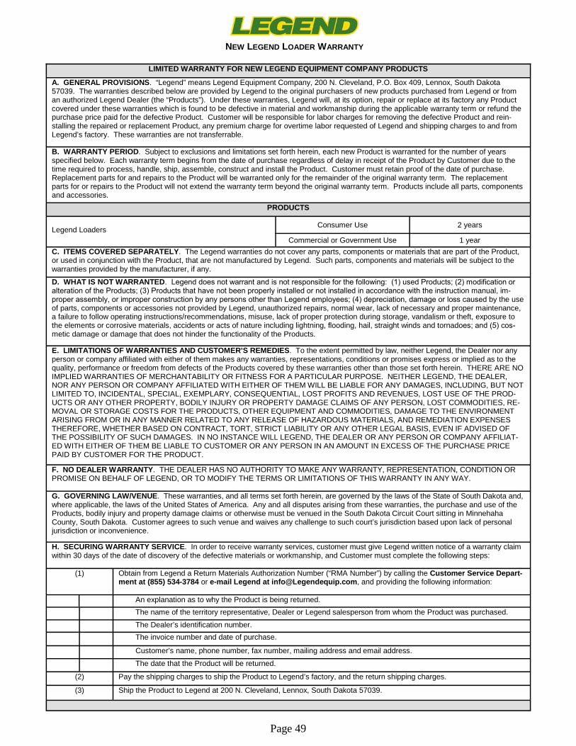
LIMITED WARRANTY FOR NEW LEGEND EQUIPMENT COMPANY PRODUCTS
A. GENERAL PROVISIONS . “Legend” means Legend Equipment Company, 200 N. Cleveland, P.O. Box 409, Lennox, South Dakota 57039. The warranties described below are provided by Legend to the original purchasers of new products purchased from Legend or from an authorized Legend Dealer (the “Products”). Under these warranties, Legend will, at its option, repair or replace at its factory any Product covered under these warranties which is found to be defective in material and workmanship during the applicable warranty term or refund the purchase price paid for the defective Product. Customer will be responsible for labor charges for removing the defective Product and rein-stalling the repaired or replacement Product, any premium charge for overtime labor requested of Legend and shipping charges to and from Legend’s factory. These warranties are not transferrable.
B. WARRANTY PERIOD . Subject to exclusions and limitations set forth herein, each new Product is warranted for the number of years specified below. Each warranty term begins from the date of purchase regardless of delay in receipt of the Product by Customer due to the time required to process, handle, ship, assemble, construct and install the Product. Customer must retain proof of the date of purchase. Replacement parts for and repairs to the Product will be warranted only for the remainder of the original warranty term. The replacement parts for or repairs to the Product will not extend the warranty term beyond the original warranty term. Products include all parts, components and accessories.
PRODUCTS
Legend Loaders
Consumer Use 2 years
Commercial or Government Use 1 year C. ITEMS COVERED SEPARATELY . The Legend warranties do not cover any parts, components or materials that are part of the Product, or used in conjunction with the Product, that are not manufactured by Legend. Such parts, components and materials will be subject to the warranties provided by the manufacturer, if any. D. WHAT IS NOT WARRANTED . Legend does not warrant and is not responsible for the following: (1) used Products; (2) modification or alteration of the Products; (3) Products that have not been properly installed or not installed in accordance with the instruction manual, im-proper assembly, or improper construction by any persons other than Legend employees; (4) depreciation, damage or loss caused by the use of parts, components or accessories not provided by Legend, unauthorized repairs, normal wear, lack of necessary and proper maintenance, a failure to follow operating instructions/recommendations, misuse, lack of proper protection during storage, vandalism or theft, exposure to the elements or corrosive materials, accidents or acts of nature including lightning, flooding, hail, straight winds and tornadoes; and (5) cos-metic damage or damage that does not hinder the functionality of the Products.
E. LIMITATIONS OF WARRANTIES AND CUSTOMER’S REMEDIES . To the extent permitted by law, neither Legend, the Dealer nor any person or company affiliated with either of them makes any warranties, representations, conditions or promises express or implied as to the quality, performance or freedom from defects of the Products covered by these warranties other than those set forth herein. THERE ARE NO IMPLIED WARRANTIES OF MERCHANTABILITY OR FITNESS FOR A PARTICULAR PURPOSE. NEITHER LEGEND, THE DEALER, NOR ANY PERSON OR COMPANY AFFILIATED WITH EITHER OF THEM WILL BE LIABLE FOR ANY DAMAGES, INCLUDING, BUT NOT LIMITED TO, INCIDENTAL, SPECIAL, EXEMPLARY, CONSEQUENTIAL, LOST PROFITS AND REVENUES, LOST USE OF THE PROD-UCTS OR ANY OTHER PROPERTY, BODILY INJURY OR PROPERTY DAMAGE CLAIMS OF ANY PERSON, LOST COMMODITIES, RE-MOVAL OR STORAGE COSTS FOR THE PRODUCTS, OTHER EQUIPMENT AND COMMODITIES, DAMAGE TO THE ENVIRONMENT ARISING FROM OR IN ANY MANNER RELATED TO ANY RELEASE OF HAZARDOUS MATERIALS, AND REMEDIATION EXPENSES THEREFORE, WHETHER BASED ON CONTRACT, TORT, STRICT LIABILITY OR ANY OTHER LEGAL BASIS, EVEN IF ADVISED OF THE POSSIBILITY OF SUCH DAMAGES. IN NO INSTANCE WILL LEGEND, THE DEALER OR ANY PERSON OR COMPANY AFFILIAT-ED WITH EITHER OF THEM BE LIABLE TO CUSTOMER OR ANY PERSON IN AN AMOUNT IN EXCESS OF THE PURCHASE PRICE PAID BY CUSTOMER FOR THE PRODUCT.
F. NO DEALER WARRANTY . THE DEALER HAS NO AUTHORITY TO MAKE ANY WARRANTY, REPRESENTATION, CONDITION OR PROMISE ON BEHALF OF LEGEND, OR TO MODIFY THE TERMS OR LIMITATIONS OF THIS WARRANTY IN ANY WAY.
G. GOVERNING LAW/VENUE . These warranties, and all terms set forth herein, are governed by the laws of the State of South Dakota and, where applicable, the laws of the United States of America. Any and all disputes arising from these warranties, the purchase and use of the Products, bodily injury and property damage claims or otherwise must be venued in the South Dakota Circuit Court sitting in Minnehaha County, South Dakota. Customer agrees to such venue and waives any challenge to such court’s jurisdiction based upon lack of personal jurisdiction or inconvenience.
H. SECURING WARRANTY SERVICE . In order to receive warranty services, customer must give Legend written notice of a warranty claim within 30 days of the date of discovery of the defective materials or workmanship, and Customer must complete the following steps:
(1) Obtain from Legend a Return Materials Authorization Number (“RMA Number”) by calling the Customer Service Depart-ment at (855) 534-3784 or e-mail Legend at [email protected] , and providing the following information:
An explanation as to why the Product is being returned. The name of the territory representative, Dealer or Legend salesperson from whom the Product was purchased. The Dealer’s identification number. The invoice number and date of purchase.
Customer’s name, phone number, fax number, mailing address and email address. The date that the Product will be returned.
(2) Pay the shipping charges to ship the Product to Legend’s factory, and the return shipping charges.
(3) Ship the Product to Legend at 200 N. Cleveland, Lennox, South Dakota 57039.
NEW LEGEND LOADER WARRANTY
TORQUE SPECIFICATIONS
Page 50
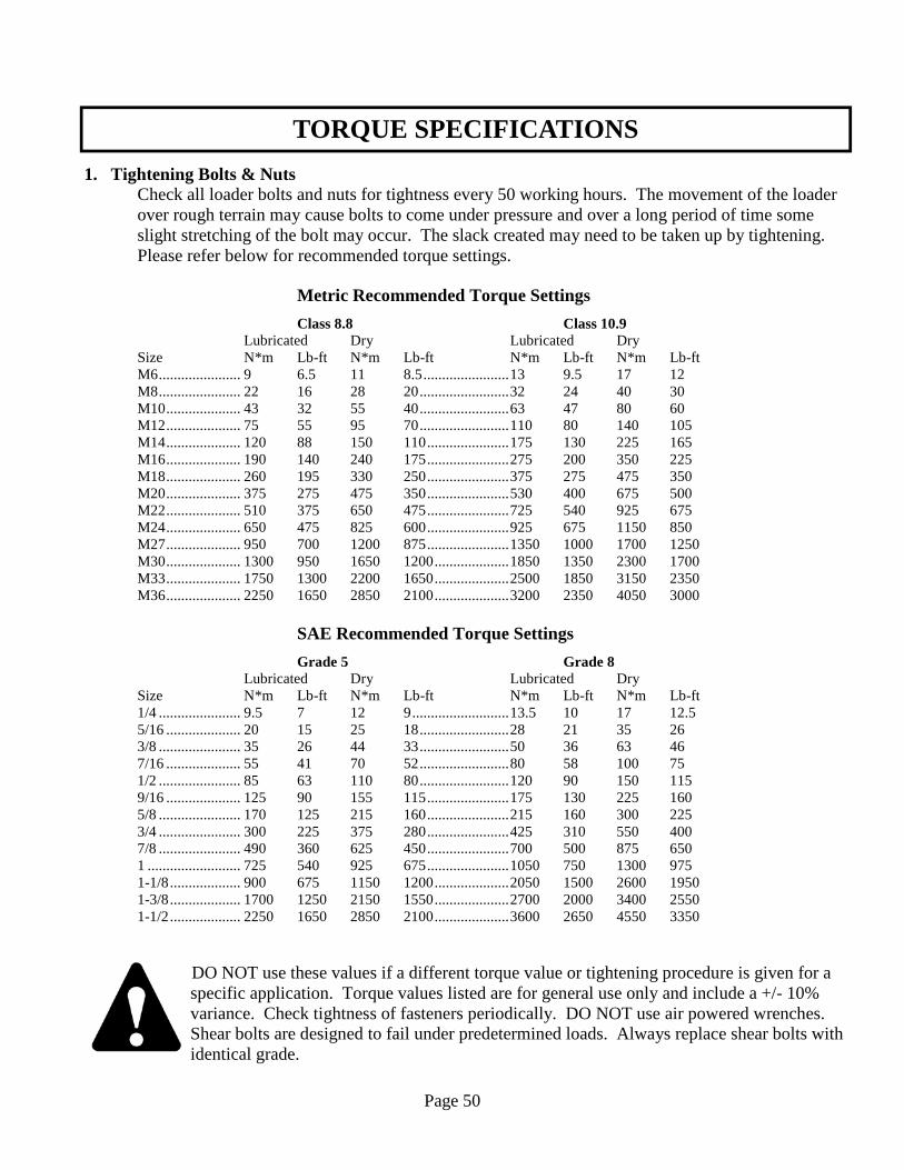
1. Tightening Bolts & Nuts Check all loader bolts and nuts for tightness every 50 working hours. The movement of the loader over rough terrain may cause bolts to come under pressure and over a long period of time some slight stretching of the bolt may occur. The slack created may need to be taken up by tightening. Please refer below for recommended torque settings. Metric Recommended Torque Settings
Class 8.8 Class 10.9 Lubricated Dry Lubricated Dry Size N*m Lb-ft N*m Lb-ft N*m Lb-ft N*m Lb-ft M6 ...................... 9 6.5 11 8.5 ....................... 13 9.5 17 12 M8 ...................... 22 16 28 20 ........................ 32 24 40 30 M10 .................... 43 32 55 40 ........................ 63 47 80 60 M12 .................... 75 55 95 70 ........................ 110 80 140 105 M14 .................... 120 88 150 110 ...................... 175 130 225 165 M16 .................... 190 140 240 175 ...................... 275 200 350 225 M18 .................... 260 195 330 250 ...................... 375 275 475 350 M20 .................... 375 275 475 350 ...................... 530 400 675 500 M22 .................... 510 375 650 475 ...................... 725 540 925 675 M24 .................... 650 475 825 600 ...................... 925 675 1150 850 M27 .................... 950 700 1200 875 ...................... 1350 1000 1700 1250 M30 .................... 1300 950 1650 1200 .................... 1850 1350 2300 1700 M33 .................... 1750 1300 2200 1650 .................... 2500 1850 3150 2350 M36 .................... 2250 1650 2850 2100 .................... 3200 2350 4050 3000 SAE Recommended Torque Settings
Grade 5 Grade 8 Lubricated Dry Lubricated Dry Size N*m Lb-ft N*m Lb-ft N*m Lb-ft N*m Lb-ft 1/4 ...................... 9.5 7 12 9 .......................... 13.5 10 17 12.5 5/16 .................... 20 15 25 18 ........................ 28 21 35 26 3/8 ...................... 35 26 44 33 ........................ 50 36 63 46 7/16 .................... 55 41 70 52 ........................ 80 58 100 75 1/2 ...................... 85 63 110 80 ........................ 120 90 150 115 9/16 .................... 125 90 155 115 ...................... 175 130 225 160 5/8 ...................... 170 125 215 160 ...................... 215 160 300 225 3/4 ...................... 300 225 375 280 ...................... 425 310 550 400 7/8 ...................... 490 360 625 450 ...................... 700 500 875 650 1 ......................... 725 540 925 675 ...................... 1050 750 1300 975 1-1/8 ................... 900 675 1150 1200 .................... 2050 1500 2600 1950 1-3/8 ................... 1700 1250 2150 1550 .................... 2700 2000 3400 2550 1-1/2 ................... 2250 1650 2850 2100 .................... 3600 2650 4550 3350
DO NOT use these values if a different torque value or tightening procedure is given for a specific application. Torque values listed are for general use only and include a +/- 10% variance. Check tightness of fasteners periodically. DO NOT use air powered wrenches. Shear bolts are designed to fail under predetermined loads. Always replace shear bolts with identical grade.

640 SPECIFICATIONSThe 640 Is The Front-
End Loader Solution To Fit The Following JD
Series Tractors:6000 Series:
6110, 6120, 6130, 6200, 6210, 6215, 6220, 6230, 6300, 6310, 6320, 6330, 6400, 6405, 6410,
6415, 6420, 6430Utility Series:
2350, 2355, 2550, 2555, 2750, 2755
640 Self-Leveling Specifications:
• Maximum lift height: 146”• Digging depth: 7”• Roll-back angle at ground
level: 38 degrees• Dump angle at maximum
height: 80 degrees• Lift & breakout capacity:
Rated at 17.5 gpm/2500 psi• Breakout force at pivot pin:
5,890 lbs.• Lift capacity to full height at
pivot pin: 3,410 lbs.
640 Non Self-Leveling Specifications:
• Maximum lift height: 146”• Digging depth: 7”• Roll-back angle at ground
level: 15 degrees• Dump angle at maximum
height: 39 degrees• Lift & breakout capacity:
Rated at 17.5 gpm/2500 psi• Breakout force at pivot pin:
5,800 lbs.• Lift capacity to full height at
pivot pin: 3,300 lbs.