4 20hr maxsonar wr/wrc™ series - maxbotix inc. · 2019-05-14 · 4-20hr-maxsonar®-wr ™ series...
TRANSCRIPT
Page 1 Web: www.maxbotix.com
PD12585m
MaxBotix®
Inc. Copyright 2005 - 2014 MaxBotix Incorporated Patent 7,679,996
4-20HR-MaxSonar® -WR™ Series
MaxBotix Inc., products are engineered and assembled in the USA.
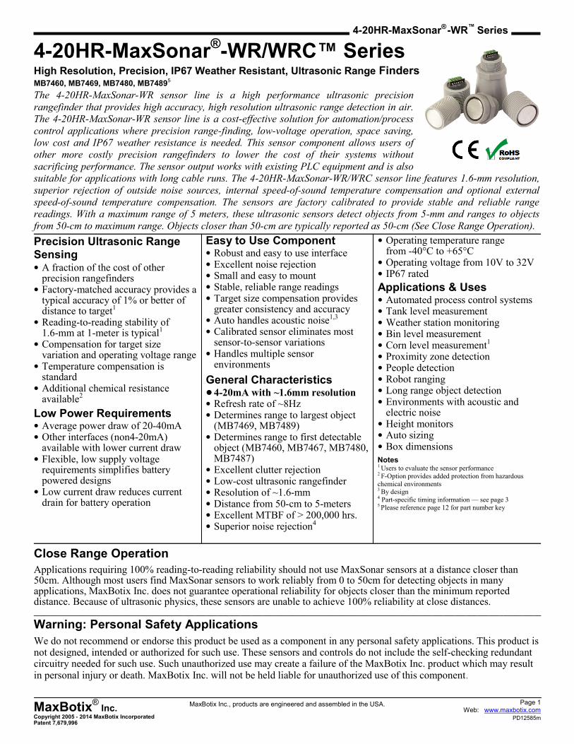
4-20HR-MaxSonar®-WR/WRC™ Series
High Resolution, Precision, IP67 Weather Resistant, Ultrasonic Range Finders MB7460, MB7469, MB7480, MB74895
The 4-20HR-MaxSonar-WR sensor line is a high performance ultrasonic precision
rangefinder that provides high accuracy, high resolution ultrasonic range detection in air.
The 4-20HR-MaxSonar-WR sensor line is a cost-effective solution for automation/process
control applications where precision range-finding, low-voltage operation, space saving,
low cost and IP67 weather resistance is needed. This sensor component allows users of
other more costly precision rangefinders to lower the cost of their systems without
sacrificing performance. The sensor output works with existing PLC equipment and is also
suitable for applications with long cable runs. The 4-20HR-MaxSonar-WR/WRC sensor line features 1.6-mm resolution,
superior rejection of outside noise sources, internal speed-of-sound temperature compensation and optional external
speed-of-sound temperature compensation. The sensors are factory calibrated to provide stable and reliable range
readings. With a maximum range of 5 meters, these ultrasonic sensors detect objects from 5-mm and ranges to objects
from 50-cm to maximum range. Objects closer than 50-cm are typically reported as 50-cm (See Close Range Operation).
Precision Ultrasonic Range Sensing • A fraction of the cost of other
precision rangefinders • Factory-matched accuracy provides a
typical accuracy of 1% or better of distance to target1
• Reading-to-reading stability of 1.6-mm at 1-meter is typical1
• Compensation for target size variation and operating voltage range
• Temperature compensation is standard
• Additional chemical resistance available2
Low Power Requirements • Average power draw of 20-40mA • Other interfaces (non4-20mA)
available with lower current draw • Flexible, low supply voltage
requirements simplifies battery powered designs
• Low current draw reduces current drain for battery operation
Easy to Use Component • Robust and easy to use interface • Excellent noise rejection • Small and easy to mount • Stable, reliable range readings • Target size compensation provides
greater consistency and accuracy • Auto handles acoustic noise1,3 • Calibrated sensor eliminates most
sensor-to-sensor variations • Handles multiple sensor
environments
General Characteristics • 4-20mA with ~1.6mm resolution • Refresh rate of ~8Hz • Determines range to largest object
(MB7469, MB7489) • Determines range to first detectable
object (MB7460, MB7467, MB7480, MB7487)
• Excellent clutter rejection • Low-cost ultrasonic rangefinder • Resolution of ~1.6-mm • Distance from 50-cm to 5-meters • Excellent MTBF of > 200,000 hrs. • Superior noise rejection4
• Operating temperature range from -40°C to +65°C
• Operating voltage from 10V to 32V • IP67 rated
Applications & Uses • Automated process control systems • Tank level measurement • Weather station monitoring • Bin level measurement • Corn level measurement1 • Proximity zone detection • People detection • Robot ranging • Long range object detection
• Environments with acoustic and electric noise
• Height monitors
• Auto sizing • Box dimensions
Close Range Operation
Applications requiring 100% reading-to-reading reliability should not use MaxSonar sensors at a distance closer than 50cm. Although most users find MaxSonar sensors to work reliably from 0 to 50cm for detecting objects in many applications, MaxBotix Inc. does not guarantee operational reliability for objects closer than the minimum reported distance. Because of ultrasonic physics, these sensors are unable to achieve 100% reliability at close distances. _______________________________________________________________________________________________________________________________________
Warning: Personal Safety Applications
We do not recommend or endorse this product be used as a component in any personal safety applications. This product is not designed, intended or authorized for such use. These sensors and controls do not include the self-checking redundant circuitry needed for such use. Such unauthorized use may create a failure of the MaxBotix Inc. product which may result in personal injury or death. MaxBotix Inc. will not be held liable for unauthorized use of this component.
Notes 1 Users to evaluate the sensor performance 2 F-Option provides added protection from hazardous
chemical environments 3 By design 4 Part-specific timing information — see page 3 5 Please reference page 12 for part number key
Page 2 Web: www.maxbotix.com
PD12585m
MaxBotix®
Inc. Copyright 2005 - 2014 MaxBotix Incorporated Patent 7,679,996
4-20HR-MaxSonar® -WR™ Series
MaxBotix Inc., products are engineered and assembled in the USA.
General Operation
The 4-20HR-MaxSonar-WR ultrasonic sensors are in-air, non-contact, object detection and ranging sensors that detect
objects within an area. These sensors are not affected by the color or other visual characteristics of the detected object.
Ultrasonic sensors use high frequency sound to detect and localize objects in a variety of environments. Ultrasonic sensors
measure the time of flight for sound that has been transmitted to and reflected back from nearby objects. Based on the
time of flight, the sensor outputs a distance value.
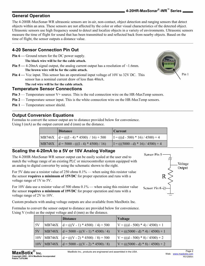
4-20 Sensor Connection Pin Out
Pin 6 — Ground return for the DC power supply.
The black wire will be for the cable attach.
Pin 5 — 4-20mA signal output, the analog current output has a resolution of ~1.6mm. The brown wire will be for the cable attach.
Pin 4 — Vcc input. This sensor has an operational input voltage of 10V to 32V DC. This
sensor has a nominal current draw of less than 40mA.
The red wire will be for the cable attach.
Temperature Sensor Connections
Pin 3 — Temperature sensor V+ source. This is the red connection wire on the HR-MaxTemp sensors.
Pin 2 — Temperature sensor input. This is the white connection wire on the HR-MaxTemp sensors.
Pin 1 — Temperature sensor shield.
_______________________________________________________________________________________________________________________________________
Output Conversion Equations Formulas to convert the sensor output are to distance provided below for convenience.
Using I (mA) as the output current and d (mm) as the distance.
_______________________________________________________________________________________________________________________________________
Scaling the 4-20mA to a 5V or 10V Analog Voltage
The 4-20HR-MaxSonar-WR sensor output can be easily scaled at the user end to
match the voltage range of an existing PLC or microcontroller system equipped with
an analog to digital converter by using the schematic shown to the right.
For 5V data use a resistor value of 250 ohms 0.1% — when using this resistor value
the sensor requires a minimum of 15VDC for proper operation and runs with a
voltage range of 1V to 5V.
For 10V data use a resistor value of 500 ohms 0.1% — when using this resistor value
the sensor requires a minimum of 19VDC for proper operation and runs with a
voltage range of 2V to 10V.
Custom products with analog voltage outputs are also available from MaxBotix Inc.
Formulas to convert the sensor output to distance are provided below for convenience.
Using V (volts) as the output voltage and d (mm) as the distance.
Pin 1
Distance Voltage
5V MB746X d = (((V - 1) * 4500) / 4) + 500 V = (((d - 500) * 4) / 4500) + 1
5V MB748X d = 5000 - (((V - 1) * 4500) / 4) V = (((5000 - d) * 4) / 4500) + 1
10V MB746X d = (((V - 2) * 4500) / 8) + 500 V = (((d - 500) * 8) / 4500) + 2
10V MB748X d = 5000 - (((V - 2) * 4500) / 8) V = (((5000 - d) * 8) / 4500) + 2
Distance Current
MB746X d = (((I - 4) * 4500) / 16) + 500 I = (((d - 500) * 16) / 4500) + 4
MB748X d = 5000 - (((I - 4) * 4500) / 16) I = (((5000 - d) * 16) / 4500) + 4
Page 3 Web: www.maxbotix.com
PD12585m
MaxBotix®
Inc. Copyright 2005 - 2014 MaxBotix Incorporated Patent 7,679,996
4-20HR-MaxSonar® -WR™ Series
MaxBotix Inc., products are engineered and assembled in the USA.
4-20HR-MaxSonar-WR (MB7460 and MB7480)
The MB7460 and MB7480 are the base models of the 4-20-MaxSonar-WR sensor line. These general purpose sensors are
recommended unless specific requirements indicate other sensors may be a better fit for the application. All other sensors
in this series are based off of this sensor model. The additional features are mentioned in their respective sections below.
_______________________________________________________________________________________________________________________________________
4-20HR-MaxSonar-WRM (MB7469 and MB7489)
The 4-20HR-MaxSonar-WRM sensors come with the most-likely filter features. The MB7469 output matches the output
of the MB7460. The MB7489 output matches the output of the MB7480.
In general, the 4-20HR-MaxSonar-WRM sensors will select the largest target from its field of view and report its range.
Even so, objects up close may provide significantly greater returns over distant objects. Users are encouraged to test the
sensor in their application to verify usability.
_______________________________________________________________________________________________________________________________________
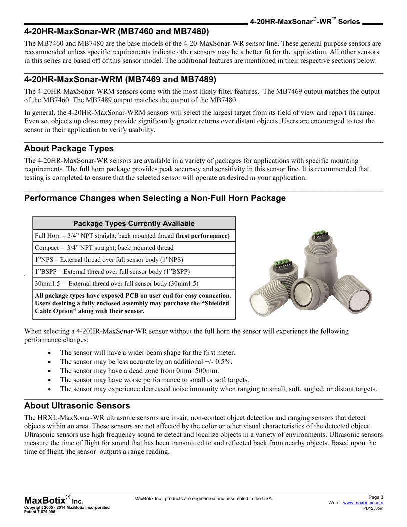
About Package Types
The 4-20HR-MaxSonar-WR sensors are available in a variety of packages for applications with specific mounting
requirements. The full horn package provides peak accuracy and sensitivity in this sensor line. It is recommended that
testing is completed to ensure that the selected sensor will operate as desired in your application.
_______________________________________________________________________________________________________________________________________ Performance Changes when Selecting a Non-Full Horn Package
When selecting a 4-20HR-MaxSonar-WR sensor without the full horn the sensor will experience the following
performance changes:
The sensor will have a wider beam shape for the first meter.
The sensor may be less accurate by an additional +/- 0.5%.
The sensor may have a dead zone from 0mm–500mm.
The sensor may have worse performance to small or soft targets.
The sensor may experience decreased noise immunity when ranging to small, soft, angled, or distant targets. _______________________________________________________________________________________________________________________________________
About Ultrasonic Sensors
The HRXL-MaxSonar-WR ultrasonic sensors are in-air, non-contact object detection and ranging sensors that detect
objects within an area. These sensors are not affected by the color or other visual characteristics of the detected object.
Ultrasonic sensors use high frequency sound to detect and localize objects in a variety of environments. Ultrasonic sensors
measure the time of flight for sound that has been transmitted to and reflected back from nearby objects. Based upon the
time of flight, the sensor outputs a range reading.
Package Types Currently Available
Full Horn – 3/4” NPT straight; back mounted thread (best performance)
Compact – 3/4” NPT straight; back mounted thread
1”NPS – External thread over full sensor body (1”NPS)
1”BSPP – External thread over full sensor body (1”BSPP)
30mm1.5 – External thread over full sensor body (30mm1.5)
All package types have exposed PCB on user end for easy connection.
Users desiring a fully enclosed assembly may purchase the “Shielded
Cable Option” along with their sensor.

Page 4 Web: www.maxbotix.com
PD12585m
MaxBotix®
Inc. Copyright 2005 - 2014 MaxBotix Incorporated Patent 7,679,996
4-20HR-MaxSonar® -WR™ Series
MaxBotix Inc., products are engineered and assembled in the USA.
Mechanical Dimensions
3/4” National Pipe Thread Straight Full Horn
1” National Pipe Thread Straight
1” BSPP Pipe Thread
30mm 1.5 Pipe Thread
A 2.87” 72.9 mm
B 1.72” dia. 43.8 mm dia.
C 0.31” 7.9 mm
D 0.58” 14.4 mm
E 2.00” 50.7 mm
F 0.31” 7.9 mm
G 0.10” 2.54 mm
H 3/4” NPS
I 1.37” dia. 34.8 mm dia.
J 1.03” dia. 26.2 mm dia.
K 0.41” 10.3 mm
L 0.78” 19.81 mm dia.
M 0.62” 15.76 mm
weight, 1.89 oz., 53.5 grams
values are nominal
Pin 1
B
D C F
G
E
H
A
M
Pin 1
L
I
J
K
A 1.58” 40.2 mm
B 1.29” dia. 33.0 mm dia.
C 0.27” 7.0 mm
D 1.30” 33.1 mm
E 0.10” 2.54 mm
F 1” NPS
G 0.40” 10.3 mm
H 0.78” 19.81 mm
I 0.62” 15.76 mm
weight, 1.28 oz., 36.3 grams
values are nominal
E
B
F
Pin 1
D C
A G
Pin 1
H I
A 1.58” 40.2 mm
B 1.29” dia. 33.0 mm dia.
C 0.27” 7.0 mm
D 1.30” 33.1 mm
E 0.10” 2.54 mm
F 1” BSPP
G 0.40” 10.3 mm
H 0.78” 19.81 mm
I 0.62” 15.76 mm
weight, 1.26 oz., 35.6 grams
values are nominal
E
F
Pin 1
D C
A G
Pin 1
H I B
A 1.58” 40.2 mm
B 1.17” dia. 29.7 mm dia.
C 0.27” 7.0 mm
D 1.24” 31.5 mm
E 0.10” 2.54 mm
F 30mm 1.5
G 0.40” 10.3 mm
H 0.78” 19.81 mm
I 0.62” 15.76 mm
weight, 1.14 oz., 32.4 grams
values are nominal
G
Pin 1
H I E
F
Pin 1
D C
A
B

Page 5 Web: www.maxbotix.com
PD12585m
MaxBotix®
Inc. Copyright 2005 - 2014 MaxBotix Incorporated Patent 7,679,996
4-20HR-MaxSonar® -WR™ Series
MaxBotix Inc., products are engineered and assembled in the USA.
Auto Calibration
The 4-20HR-MaxSonar-WR series sensor auto calibrates each time it takes a range reading. The sensor then uses this data
to range objects. If the temperature, humidity or applied voltage changes during sensor operation the sensor will continue
to function normally over the rated temperature range while applying compensation for changes caused by temperature
and voltage.
_______________________________________________________________________________________________________________________________________
Sensors Minimum Distance
The MB7460 and MB7480 are the base models of the 4-20HR-MaxSonar-WR sensor line. Sensors based on the MB7460
have a relative zero set at 4mA (4mA = 500 mm; 20mA = 5000 mm) and the sensors based on the MB7480 have a relative
zero of 20mA (20mA = 500 mm; 4mA = 5000 mm).
_______________________________________________________________________________________________________________________________________
Range Zero Location
In general, the 4-20HR-MaxSonar-WR sensors report the range to the leading edge of the closest detectable object. Target
detection is characterized in the sensor beam patterns.
The 4-20HR-MaxSonar-WR reports the range to distant targets from where the threading and nut meet on the sensor
housing as shown in the diagrams below.
Range Zero
0.0 mm Target Face The range is measured from where the housing meets the threading.
Range Zero
0.0 mm Target Face The range is measured from the front of the sensor.

Page 6 Web: www.maxbotix.com
PD12585m
MaxBotix®
Inc. Copyright 2005 - 2014 MaxBotix Incorporated Patent 7,679,996
4-20HR-MaxSonar® -WR™ Series
MaxBotix Inc., products are engineered and assembled in the USA.
Temperature Compensation
The speed of sound in air increases by approximately 0.6 meters per second, per degree centigrade. An external
temperature sensor (supplied Dongle or optional HR-MaxTemp) allows for immediate and accurate temperature
compensation. Optionally, the 4-20HR-MaxSonar-WR has a built in temperature sensor.
Using the Attached Temperature Sensor Dongle
The 4-20HR-MaxSonar-WR includes an attached temperature sensor dongle. This dongle allows immediate and accurate
temperature sensing of the air temperature at the sensor. This provides a typical accuracy of 1.5%, (excluding major
temperature changes along the measurement path).
Using the External HR-MaxTemp — External Temperature Sensor
The temperature measured at the sensor itself may not match the air temperature of the full path between the sensor and
the target. For example, sensors can be mounted in vertical applications or applications where the environment
temperature gradient is severe. Users may experience a temperature measurement error which will affect the sensor
accuracy. For example, buildings with a height of 3-meters can have floor-to-ceiling temperature variations of 5°C or
more. Because of these temperature effects, users desiring the highest accuracy output are encouraged to use an external
temperature mounted midway between the target and the sensor.
For best results in these applications, users are encouraged to remove the dongle and connect the HR-MaxTemp sensor
midway between the HRXL-MaxSonar-WR and the expected target. (Remove the dongle and attach the HR-MaxTemp.
This provides a typical distance accuracy of 1% or better.
Using the Optional Internal Temperature Sensor
The temperature dongle can be removed and the sensor repowered to enable the internal temperature sensor. This internal
temperature sensor does not track the temperature changes as well as the external temperature sensors. Even so, if there
are significant changes in temperature from the air around the back of the sensor (where the dongle is located) to the air in
front of the sensor (where the transducer is located) and an external HR-MaxTemp is not practical for your application,
using the internal temperature sensor is the best option. After a power up, the typical distance accuracy will be 3%.
Self-Heating
The operational characteristics of the sensor cause a natural self-heating effect. Because of the variability in the
self-heating effect caused by changes in current output, the accuracy of the internal temperature sensor is limited. While
the sensor will compensate for most of the self-heating effects, the surrounding environment and mounting can affect the
amount of self heating.
Power cycling the sensor may cause self-heating effects that cannot be predicted by the sensor’s data algorithms. It is
recommended to run the sensor continuously. This steady-state operation helps to minimize reading-to-reading variability
by increasing the stability of the internal temperature of the sensor.
Sensors with different output choices that are not subject to this self-heating effect are also available from MaxBotix.
______________________________________________________________________________________________________________________________________
Target Size Compensation
Most low-cost ultrasonic rangefinders report the range to smaller size targets as farther than the actual distance. They may
also report the range to larger size targets as closer than the actual distance.
The 4-20HR-MaxSonar-WR sensor line compensates for target size differences. This means that, provided an object is
large enough to be detected, the sensor will report the same distance regardless of target size. Smaller targets can have
additional detection noise that may limit this feature. In addition, targets with small or rounded surfaces may have an
apparent distance that is slightly farther, where the distance reported may be a composite of the sensed object(s).
_______________________________________________________________________________________________________________________________________
Supply Voltage Compensation
During power-up the 4-20HR-MaxSonar-WR sensor line auto calibrates for changes in supply voltage. The sensor also
compensates if the supplied voltage gradually changes.
The sensor requires noise free power for best operation. If the sensor is used with noise on the supplied power or ground,
the readings may be affected. In general, the 4-20HR-MaxSonar-WR will not be affected by supply voltage changes
provided the voltage applied remains above 10V.

Page 7 Web: www.maxbotix.com
PD12585m
MaxBotix®
Inc. Copyright 2005 - 2014 MaxBotix Incorporated Patent 7,679,996
4-20HR-MaxSonar® -WR™ Series
MaxBotix Inc., products are engineered and assembled in the USA.
Sensor Timing / Power-Up Timing
A. Power-Up timing begins when a voltage above 10V is maintained for the sensor.
B. After a ~125mS delay the sensor will idle at a low current state (4mA).
C. The 4-20HR-MaxSonar-WR is has data available for the user ~345mS after power-up.
D. Range data is sent every ~125mS thereafter, meaning that after the initial power-up, the sensor refresh rate is ~8Hz.
The 4-20HR-MaxSonar-WR series sensors use an internal filter to process range data. This filter improves the sensor’s
performance for accuracy, noise rejection and reading-to-reading stability. This filter responds to rapid large changes in
target position at a rate of 1.1Hz. This filter does not affect the speed at which data is made available to the user, but
allows for more consistent range information.
_______________________________________________________________________________________________________________________________________
Custom Solutions
We have the ultrasonic sensor for you! If you don't find the product for your specific application, contact us and our
engineers will work with you for your custom solution. Our in-house engineering department can design and manufacture
custom solutions which are subject to a small NRE fee. Some of these custom solutions may later be incorporated into our
standard products.
Page 8 Web: www.maxbotix.com
PD12585m
MaxBotix®
Inc. Copyright 2005 - 2014 MaxBotix Incorporated Patent 7,679,996
4-20HR-MaxSonar® -WR™ Series
MaxBotix Inc., products are engineered and assembled in the USA.
Sensor Operation
The 4-20HR-MaxSonar-WR sensors are designed to be used in a variety of outdoor industrial environments or indoor
environments. Many acoustic noise sources have little to no effect on the reported range of the 4-20HR-MaxSonar-WR
sensors. Most range readings are accurately reported. If the range readings are affected, it is typically less than 5-mm. This
allows users to employ real-time ultrasonic distance sensing without the need for additional supporting circuitry or
complex user software.
Multiple 4-20HR-MaxSonar-WR sensors can be operated in the same general locations. The internal noise filter is able to
filter out the ultrasonic noise from other 4-20HR-MaxSonar-WR sensors with minimal interference. Typically, when
operating with multiple sensors, the range readings will be within ±1 cm of the actual range to the intended target.
The 4-20HR-MaxSonar-WR sensors use an internal filter to process range data. This filter improves the sensor’s
performance for accuracy, noise rejection and reading-to-reading stability. The filtering during operation also permits
additional acoustic and electric noise tolerance. This filter is applied to all readings and updates at a rate of 1.1Hz.
_______________________________________________________________________________________________________________________________________
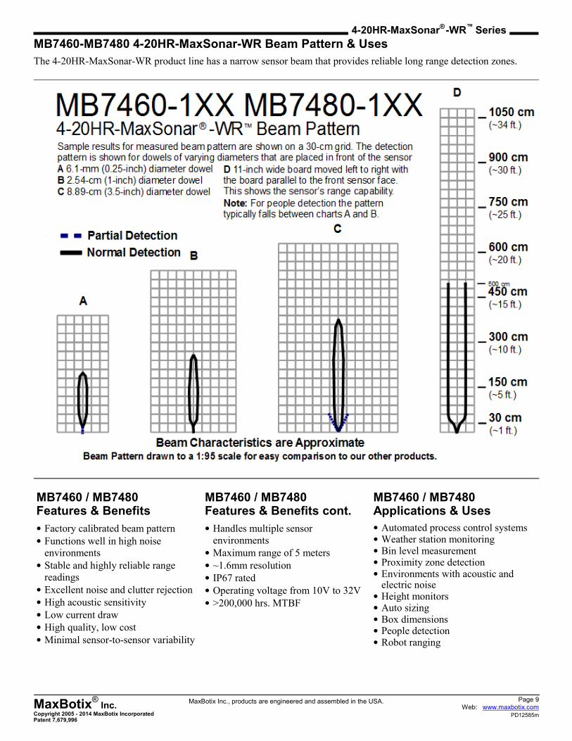
Beam Patterns Background
Each 4-20HR-MaxSonar-WR sensor has a calibrated beam pattern. Each sensor is matched to provide
the approximate detection pattern shown in this datasheet. This allows users to select the part number
that matches their given sensing application. Each part number has a consistent field of detection so
additional units of the same part number will have similar beam patterns. The beam patterns are
provided to help identify an estimated detection zone for an application based on the acoustic
properties of a target.
Each beam pattern is a 2D representation of the detection area of the sensor. The beam pattern is
actually shaped like a 3D cone (having the same pattern both vertically and horizontally). Beam
patterns for dowels are used to show the beam pattern of each sensor. Dowels are long cylindrical
targets of a given diameter. The dowels provide consistent target detection characteristics for a given
size target which allows easy comparison of one MaxSonar sensor to another MaxSonar sensor.
For each part number, the four patterns (A, B, C and D) represent the detection zone for a given target
size. Each beam pattern shown is determined by the sensor’s part number and target size.
The actual beam angle changes over the full range. Use the beam pattern for a specific target at any given distance to
calculate the beam angle for that target at the specific distance. Generally, smaller targets are detected over a narrower
beam angle and a shorter distance. Larger targets are detected over a wider beam angle and a longer distance.
People Sensing
For users who
need to detect
people, the
detection area to
the 1-inch
diameter dowel
generally
represents the
area that the
sensor will
reliably detect
people.
Page 9 Web: www.maxbotix.com
PD12585m
MaxBotix®
Inc. Copyright 2005 - 2014 MaxBotix Incorporated Patent 7,679,996
4-20HR-MaxSonar® -WR™ Series
MaxBotix Inc., products are engineered and assembled in the USA.
MB7460-MB7480 4-20HR-MaxSonar-WR Beam Pattern & Uses
The 4-20HR-MaxSonar-WR product line has a narrow sensor beam that provides reliable long range detection zones.
MB7460 / MB7480 Features & Benefits
• Factory calibrated beam pattern
• Functions well in high noise
environments
• Stable and highly reliable range
readings
• Excellent noise and clutter rejection
• High acoustic sensitivity
• Low current draw
• High quality, low cost
• Minimal sensor-to-sensor variability
MB7460 / MB7480 Applications & Uses
• Automated process control systems • Weather station monitoring • Bin level measurement • Proximity zone detection • Environments with acoustic and
electric noise • Height monitors • Auto sizing • Box dimensions • People detection • Robot ranging
MB7460 / MB7480 Features & Benefits cont.
• Handles multiple sensor
environments
• Maximum range of 5 meters
• ~1.6mm resolution
• IP67 rated
• Operating voltage from 10V to 32V
• >200,000 hrs. MTBF
Page 10 Web: www.maxbotix.com
PD12585m
MaxBotix®
Inc. Copyright 2005 - 2014 MaxBotix Incorporated Patent 7,679,996
4-20HR-MaxSonar® -WR™ Series
MaxBotix Inc., products are engineered and assembled in the USA.
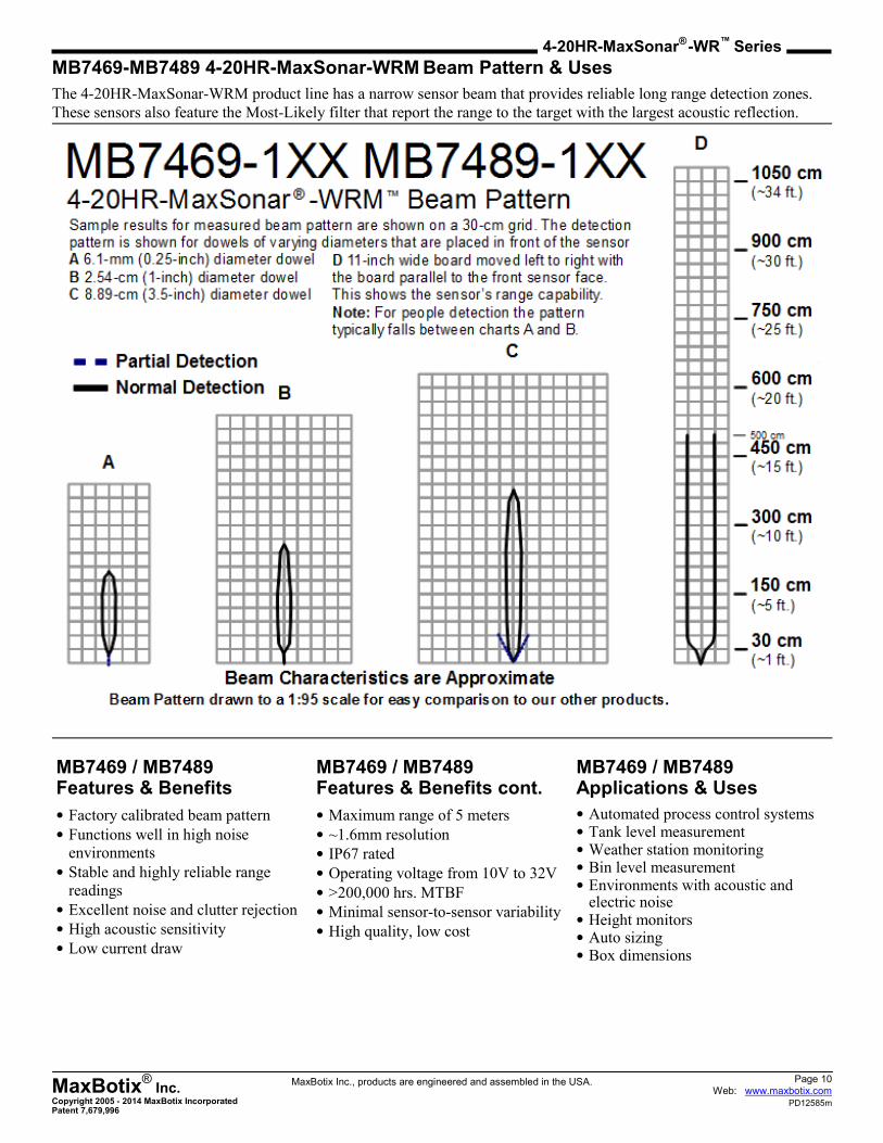
MB7469-MB7489 4-20HR-MaxSonar-WRM Beam Pattern & Uses
The 4-20HR-MaxSonar-WRM product line has a narrow sensor beam that provides reliable long range detection zones.
These sensors also feature the Most-Likely filter that report the range to the target with the largest acoustic reflection.
MB7469 / MB7489 Features & Benefits
• Factory calibrated beam pattern
• Functions well in high noise
environments
• Stable and highly reliable range
readings
• Excellent noise and clutter rejection
• High acoustic sensitivity
• Low current draw
MB7469 / MB7489 Applications & Uses
• Automated process control systems • Tank level measurement • Weather station monitoring • Bin level measurement • Environments with acoustic and
electric noise • Height monitors • Auto sizing • Box dimensions
MB7469 / MB7489 Features & Benefits cont.
• Maximum range of 5 meters
• ~1.6mm resolution
• IP67 rated
• Operating voltage from 10V to 32V
• >200,000 hrs. MTBF
• Minimal sensor-to-sensor variability
• High quality, low cost
Page 11 Web: www.maxbotix.com
PD12585m
MaxBotix®
Inc. Copyright 2005 - 2014 MaxBotix Incorporated Patent 7,679,996
4-20HR-MaxSonar® -WR™ Series
MaxBotix Inc., products are engineered and assembled in the USA.
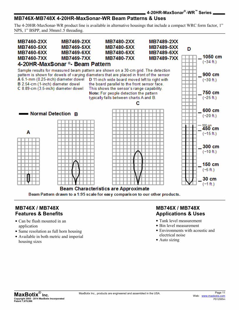
MB746X-MB748X 4-20HR-MaxSonar-WR Beam Patterns & Uses
The 4-20HR-MaxSonar-WR product line is available in alternative housings that include a compact WRC form factor, 1”
NPS, 1” BSPP, and 30mm1.5 threading.
MB746X / MB748X Features & Benefits
• Can be flush mounted in an
application
• Same resolution as full horn housing
• Available in both metric and imperial
housing sizes
MB746X / MB748X Applications & Uses
• Tank level measurement • Bin level measurement • Environments with acoustic and
electrical noise • Auto sizing
Page 12 Web: www.maxbotix.com
PD12585m
MaxBotix®
Inc. Copyright 2005 - 2014 MaxBotix Incorporated Patent 7,679,996
4-20HR-MaxSonar® -WR™ Series
MaxBotix Inc., products are engineered and assembled in the USA.
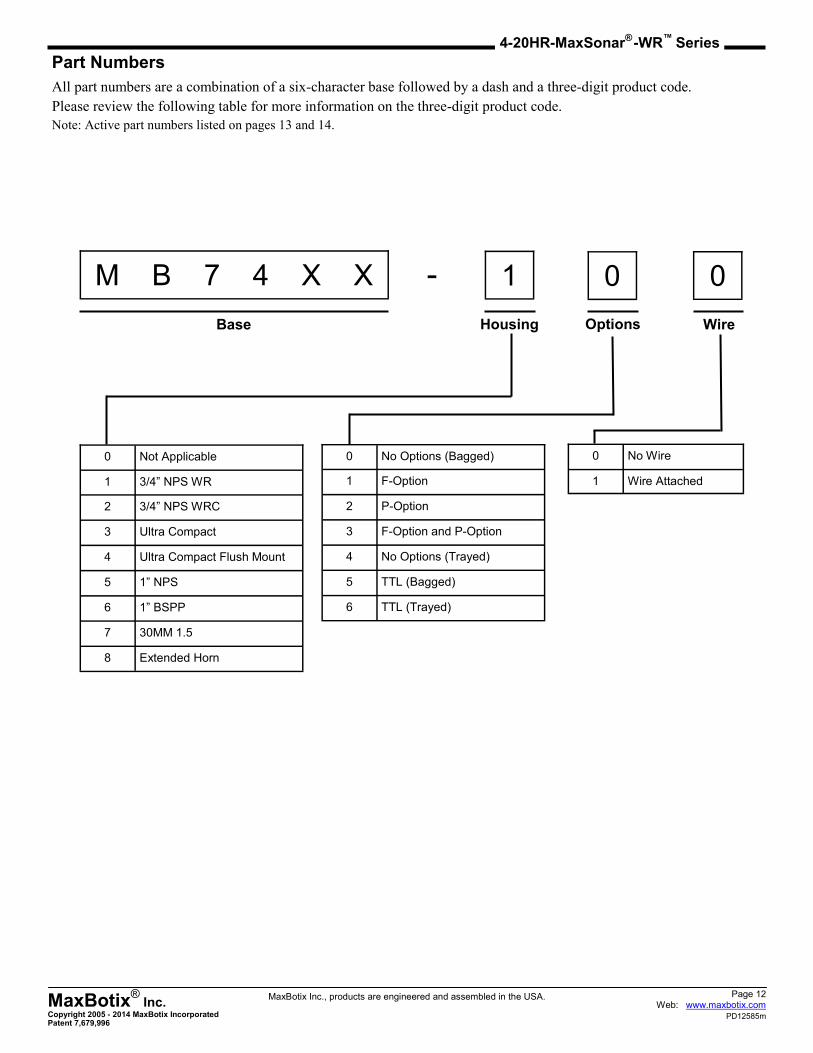
Part Numbers
All part numbers are a combination of a six-character base followed by a dash and a three-digit product code.
Please review the following table for more information on the three-digit product code.
Note: Active part numbers listed on pages 13 and 14.
M B 7 4 X X - 1 0 0
Base Housing Options Wire
0 Not Applicable
1 3/4” NPS WR
2 3/4” NPS WRC
3 Ultra Compact
4 Ultra Compact Flush Mount
5 1” NPS
6 1” BSPP
7 30MM 1.5
8 Extended Horn
0 No Options (Bagged)
1 F-Option
2 P-Option
3 F-Option and P-Option
4 No Options (Trayed)
5 TTL (Bagged)
6 TTL (Trayed)
0 No Wire
1 Wire Attached

Page 13 Web: www.maxbotix.com
PD12585m
MaxBotix®
Inc. Copyright 2005 - 2014 MaxBotix Incorporated Patent 7,679,996
4-20HR-MaxSonar® -WR™ Series
MaxBotix Inc., products are engineered and assembled in the USA.
The following tables display all of the active and valid part numbers for these products.
Active Part Numbers for MB7460
MB7460-100 MB7460-101 MB7460-110 MB7460-111 MB7460-120 MB7460-121 MB7460-130 MB74760-131
MB7460-200 MB7460-201 MB7460-210 MB7460-211 MB7460-220 MB7460-221 MB7460-230 MB7460-231
MB7460-500 MB7460-501 MB7460-510 MB7460-511 MB7460-520 MB7460-521 MB7460-530 MB7460-531
MB7460-600 MB7460-601 MB7460-610 MB7460-611 MB7460-620 MB7460-621 MB7460-630 MB7460-631
MB7460-700 MB7460-701 MB7460-710 MB7460-711 MB7460-720 MB7460-721 MB7460-730 MB7460-731
Active Part Numbers for MB7469
MB7469-100 MB7469-101 MB7469-110 MB7469-111 MB7469-120 MB7469-121 MB7469-130 MB7469-131
MB7469-200 MB7469-201 MB7469-210 MB7469-211 MB7469-220 MB7469-221 MB7469-230 MB7469-231
MB7469-500 MB7469-501 MB7469-510 MB7469-511 MB7469-520 MB7469-521 MB7469-530 MB7469-531
MB7469-600 MB7469-601 MB7469-610 MB7469-611 MB7469-620 MB7469-621 MB7469-630 MB7469-631
MB7469-700 MB7469-701 MB7469-710 MB7469-711 MB7469-720 MB7469-721 MB7469-730 MB7469-731
Active Part Numbers for MB7480
MB7480-100 MB7480-101 MB7480-110 MB7480-111 MB7480-120 MB7480-121 MB7480-130 MB7480-131
MB7480-200 MB7480-201 MB7480-210 MB7480-211 MB7480-220 MB7480-221 MB7480-230 MB7480-231
MB7480-500 MB7480-501 MB7480-510 MB7480-511 MB7480-520 MB7480-521 MB7480-530 MB7480-531
MB7480-600 MB7480-601 MB7480-610 MB7480-611 MB7480-620 MB7480-621 MB7480-630 MB7480-631
MB7480-700 MB7480-701 MB7480-710 MB7480-711 MB7480-720 MB7480-721 MB7480-730 MB7480-731
Active Part Numbers for MB7489
MB7489-100 MB7489-101 MB7489-110 MB7489-111 MB7489-120 MB7489-121 MB7489-130 MB7489-131
MB7489-200 MB7489-201 MB7489-210 MB7489-211 MB7489-220 MB7489-221 MB7489-230 MB7489-231
MB7489-500 MB7489-501 MB7489-510 MB7489-511 MB7489-520 MB7489-521 MB7489-530 MB7489-531
MB7489-600 MB7489-601 MB7489-610 MB7489-611 MB7489-620 MB7489-621 MB7489-630 MB7489-631
MB7489-700 MB7489-701 MB7489-710 MB7489-711 MB7489-720 MB7489-721 MB7489-730 MB7489-731
Page 14 Web: www.maxbotix.com
PD12585m
MaxBotix®
Inc. Copyright 2005 - 2014 MaxBotix Incorporated Patent 7,679,996
4-20HR-MaxSonar® -WR™ Series
MaxBotix Inc., products are engineered and assembled in the USA.
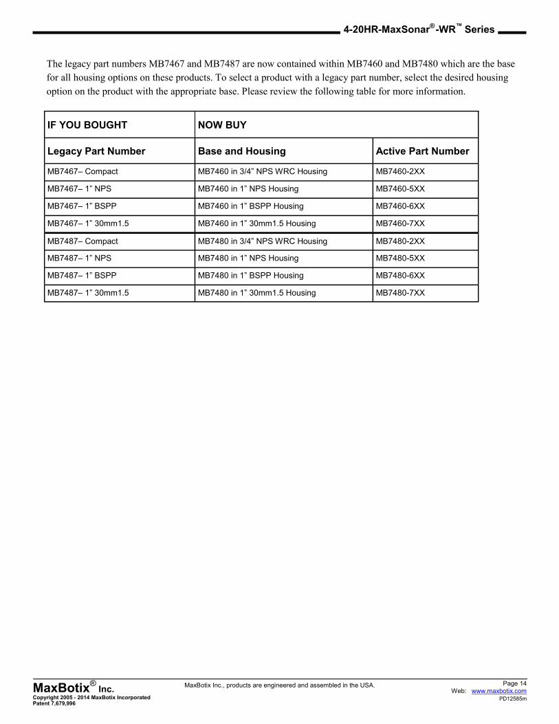
The legacy part numbers MB7467 and MB7487 are now contained within MB7460 and MB7480 which are the base
for all housing options on these products. To select a product with a legacy part number, select the desired housing
option on the product with the appropriate base. Please review the following table for more information.
IF YOU BOUGHT NOW BUY
Legacy Part Number Base and Housing Active Part Number
MB7467– Compact MB7460 in 3/4” NPS WRC Housing MB7460-2XX
MB7467– 1” NPS MB7460 in 1” NPS Housing MB7460-5XX
MB7467– 1” BSPP MB7460 in 1” BSPP Housing MB7460-6XX
MB7467– 1” 30mm1.5 MB7460 in 1” 30mm1.5 Housing MB7460-7XX
MB7487– Compact MB7480 in 3/4” NPS WRC Housing MB7480-2XX
MB7487– 1” NPS MB7480 in 1” NPS Housing MB7480-5XX
MB7487– 1” BSPP MB7480 in 1” BSPP Housing MB7480-6XX
MB7487– 1” 30mm1.5 MB7480 in 1” 30mm1.5 Housing MB7480-7XX
Page 15 Web: www.maxbotix.com
PD12585m
MaxBotix®
Inc. Copyright 2005 - 2014 MaxBotix Incorporated Patent 7,679,996
4-20HR-MaxSonar® -WR™ Series
MaxBotix Inc., products are engineered and assembled in the USA.
After reviewing this datasheet, do you have any more questions?
We offer Technical Support on all of our products even if you purchased them through one of our many vendors
worldwide.
You can fill out a Technical Support form for assistance on a sensor here --> Technical Support
Not sure which sensor you need for your application?
We offer Sensor Selection Assistance, click the link here to fill out a form for support --> Sensor Selection Help
Looking for tutorials to help you get started?
Frequently Asked Questions about Our Sensors
We receive many questions about our products and services. This resource offers answers to common inquiries
we receive about our product lines and their application.
Fully Calibrated Beam Patterns
All of our sensors are factory calibrated to provide consistent beam patterns, detection zones, to fit into a wide
variety of applications. In our product lines, each model number comes with a different beam pattern that reflects
the sensitivity and the detection zone of how it sees a target. Additionally, we strive to maintain consistency be-
tween our finished products, and you will see little to no deviation between sensors of the same model. This al-
lows you to have confidence in your final application when using multiple sensors.
Understanding Range Readings
The success of an application may hinge upon knowing the exact location of a target. However, a sensor may
report one meter even if the target is not exactly one meter away from the sensor. Sensor specifications, such as
resolution, precision, and accuracy, help you to understand sensor performance.
How to Use Multiple Ultrasonic Sensors
This guide covers three ways to run your sensors in a Multiple Sensor environment and issues you may face.
Contact us now with any questions at [email protected] or call +1-218-454-0766.
Please call during our preferred business hours of 8:00 am – 4:30 pm EST on Monday through Thursday and 8:00 am –
2:00 pm EST on Friday, or you may leave us a voicemail anytime.