10-0 70, cybe rcat 50 - koltek |proyectos contra incendios · 10-0 addr 70, essab op cybe le fire...
TRANSCRIPT
10-0Addr
070, ressab
Op
Cybeble Fire
perati
erCae Alarm
ion &
at® 50m Cont
Main
0 trol Sy
tenan
ystem
nce M
P/N 06-368Au
anual
8-2, Rev. 4ugust 2013
l
DEVELOPED BY Fike 704 SW 10th Street P.O. Box 610 Blue Springs, Missouri 64013 U.S.A. Phone: (888) 628-FIKE (3453) (816) 229-3405 Fax: (866) 211-9239
COPYRIGHT NOTICE Copyright © 2011. All rights reserved.
Fike copyrights this manual and products it describes. You may not reproduce, transmit, transcribe, or any part of this manual without express, written permission from Fike.
This manual contains proprietary information intended for distribution to authorized persons or companies for the sole purpose of conducting business with Fike. If you distribute any information contained in this manual to unauthorized persons, you have violated all distributor agreements and we may take legal action.
TRADEMARKS Fike© is a registered trademark of Fike. CyberCat® is a registered trademark of Fike.
QUALITY Fike has maintained ISO 9001 certification since 1996. Prior to shipment, we thoroughly test our products and review our documentation to assure the highest quality in all respects.
WARRANTY Fike provides a one-year limited manufacturer’s warranty on this product. All warranty returns must be returned from an authorized Fike Distributor. Contact Fike’s Marketing department for further warranty information.
Fike maintains a repair department that is available to repair and return existing electronic components or exchange/purchase previously repaired inventory component (advance replacement). All returns must be approved prior to return. A Material Return Authorization (MRA) number must be indicated on the box of the item being returned. Contact the appropriate Regional Sales Manager for further information regarding product return procedures.
LIMITATIONS OF LIABILITY Installation in accordance with this manual, applicable codes, and the instructions of the Authority Having Jurisdiction is mandatory. Fike can not be held liable for any incidental or consequential damages arising from the loss of property or other damages or losses resulting from the use or misuse of Fike products beyond the cost of repair or replacement of any defective components. Fike reserves the right to make product improvements and change product specifications at any time.
While every precaution has been taken during the preparation of this manual to ensure the accuracy of its content, Fike assumes no responsibility for errors or omissions.
CONTENTS
UL S2203 CyberCat 50 Operation Manual i FM 3029134 P/N: 06-368-2 Rev 4, 08/2013
REVISION HISTORY Document Title: CyberCat 50 Addressable Fire Alarm System Operation and Maintenance Manual
Document Reorder Number: 06-368-2
Revision Section Date Reason for Change
3 All Sections 04/2012
Separated manual into separate Installation, Operation and Programming
Manuals; added MNS updates; added FAAST detector updates
4 Sections 1, 3, 6, and Appendix A 08/2013 Added programming features for AHU
restart, audio sync, and MNS activation via SLC input modules.
CONTENTS
ii CyberCat 50 Operation Manual UL S2203 Rev 4, 08/2013 P/N: 06-368-2 FM 3029134
TABLE OF CONTENTS SECTION DESCRIPTION PAGE
1.0 Introduction .................................................................................................................... 1-1 1.1 About This Manual ........................................................................................................... 1-1 1.2 Product Support ............................................................................................................... 1-1 1.3 Safety Information ............................................................................................................ 1-1 1.4 Related Documentation ................................................................................................... 1-1 1.5 Understanding CyberCat 50 ............................................................................................ 1-2
1.5.1 System Controller ............................................................................................................. 1-2 1.5.2 Intelligent Addressable Devices ....................................................................................... 1-2 1.5.3 Peripheral Devices ........................................................................................................... 1-2 1.5.4 Emergency Communication System ................................................................................ 1-3
1.6 UL Operational Limitations ............................................................................................... 1-4
2.0 User Interface ................................................................................................................. 2-1 2.1 CyberCat 50 Main Display ............................................................................................... 2-1
2.1.1 System Status LEDs ........................................................................................................ 2-2 2.1.2 History Navigation Buttons ............................................................................................... 2-3 2.1.3 Control Buttons ................................................................................................................ 2-3 2.1.4 Navigation and Function Buttons ..................................................................................... 2-4 2.1.5 LCD Display ..................................................................................................................... 2-5
2.1.5.1 System Normal Display .................................................................................................... 2-5 2.1.5.2 System Event Display ...................................................................................................... 2-6 2.1.5.3 Top Level Menu ............................................................................................................... 2-7
2.2 Password Protection ........................................................................................................ 2-8 2.2.1 Logging onto the System ................................................................................................. 2-9 2.2.2 Changing the System Administrator Password ............................................................... 2-9
3.0 System Operation .......................................................................................................... 3-1 3.1 General Operation ............................................................................................................ 3-1
3.1.1 AC Trouble Delay ............................................................................................................. 3-1 3.1.2 Daylight Savings .............................................................................................................. 3-1 3.1.3 Silence Inhibit ................................................................................................................... 3-1 3.1.4 Silence Reminder ............................................................................................................. 3-2 3.1.5 State Counters ................................................................................................................. 3-2 3.1.6 Network Operation ........................................................................................................... 3-2 3.1.7 Positive Alarm Sequence ................................................................................................. 3-2 3.1.8 Emergency Communication Operation ............................................................................ 3-3
3.1.8.1 Voice System Priorities .................................................................................................... 3-4 3.1.9 Device LED Operation ..................................................................................................... 3-4
3.2 Panel Menu Structure ...................................................................................................... 3-4 3.3 Panel Operation by Event ................................................................................................ 3-5
3.3.1 Power-Up Reset ............................................................................................................... 3-5 3.3.2 Normal State .................................................................................................................... 3-6 3.3.3 Alarm/Waterflow State ..................................................................................................... 3-7 3.3.4 Alarm Verification ............................................................................................................. 3-8 3.3.5 Summing Alarm State ...................................................................................................... 3-9 3.3.6 Trouble State .................................................................................................................. 3-10 3.3.7 Supervisory State ........................................................................................................... 3-11 3.3.8 Pre-Alarm State .............................................................................................................. 3-12 3.3.9 Process State ................................................................................................................. 3-13 3.3.10 Zone Disable State ......................................................................................................... 3-14 3.3.11 Drill State ........................................................................................................................ 3-15 3.3.12 Walk-Test Operation ...................................................................................................... 3-16
CONTENTS
UL S2203 CyberCat 50 Operation Manual iii FM 3029134 P/N: 06-368-2 Rev 4, 08/2013
SECTION DESCRIPTION PAGE 3.3.13 Fan Restart Operation ................................................................................................... 3-17
3.3.13.1 AHU Fire Key ................................................................................................................. 3-17 3.4 Intelligent Sensor Features............................................................................................ 3-18
3.4.1 Alarm Verification .......................................................................................................... 3-18 3.4.2 Pre-Alarm....................................................................................................................... 3-18 3.4.3 Acclimate ....................................................................................................................... 3-19 3.4.4 Drift Compensation ........................................................................................................ 3-19 3.4.5 Day/Night/Holiday Settings ............................................................................................ 3-19 3.4.6 Flame Enhance ............................................................................................................. 3-19 3.4.7 Summing........................................................................................................................ 3-19 3.4.8 Smolder ......................................................................................................................... 3-19 3.4.9 Walk-Test....................................................................................................................... 3-19
4.0 System History .............................................................................................................. 4-1 4.1 Overview .......................................................................................................................... 4-1 4.2 Viewing History ................................................................................................................ 4-1
4.2.1 Alarm History ................................................................................................................... 4-3 4.2.2 Supervisory History ......................................................................................................... 4-3 4.2.3 Trouble History ................................................................................................................ 4-4 4.2.4 Events History ................................................................................................................. 4-4 4.2.5 Zone History .................................................................................................................... 4-5 4.2.6 Erase History ................................................................................................................... 4-5 4.2.7 Viewing Additional Event Information .............................................................................. 4-6
5.0 System Diagnostics ...................................................................................................... 5-1 5.1 Overview .......................................................................................................................... 5-1 5.2 Diagnosing Problems ...................................................................................................... 5-1 5.3 Removing or Replacing Panel Components ................................................................... 5-1 5.4 Removing or Replacing Field Devices ............................................................................ 5-2 5.5 Diagnostic Menu 1 ........................................................................................................... 5-3
5.5.1 Device Diagnostic ............................................................................................................ 5-3 5.5.1.1 Device Type, Location and LED Diagnostic .................................................................... 5-4 5.5.1.2 Device Serial Number Diagnostic .................................................................................... 5-5
5.5.2 Value 1 Diagnostic ........................................................................................................... 5-6 5.5.3 Value 2 Diagnostic ........................................................................................................... 5-7 5.5.4 LED Test .......................................................................................................................... 5-7 5.5.5 CRC (Cyclic Redundancy Count) .................................................................................... 5-7
5.6 Diagnostic Menu 2 ........................................................................................................... 5-8 5.6.1 Keypad Diagnostic ........................................................................................................... 5-8 5.6.2 VESDA 1 Diagnostic ........................................................................................................ 5-9 5.6.3 VESDA 2 Diagnostic ...................................................................................................... 5-10 5.6.4 Peripheral Diagnostic .................................................................................................... 5-10
5.6.4.1 Fire-Phone Diagnostic ................................................................................................... 5-11 5.6.5 VESDAnet Communications.......................................................................................... 5-12
5.7 Diagnostic Menu 3 ......................................................................................................... 5-13 5.7.1 Network Diagnostic 1 ..................................................................................................... 5-13 5.7.2 Network Diagnostic 2 ..................................................................................................... 5-14 5.7.3 Network Diagnostic 3 ..................................................................................................... 5-15 5.7.4 History Diagnostic .......................................................................................................... 5-15 5.7.5 Board Communication Diagnostics ............................................................................... 5-16
CONTENTS
iv CyberCat 50 Operation Manual UL S2203 Rev 4, 08/2013 P/N: 06-368-2 FM 3029134
SECTION DESCRIPTION PAGE 5.8 Diagnostic Menu 4 ......................................................................................................... 5-16
5.8.1 Amplifier Operation Status ............................................................................................. 5-17 5.8.2 Amplifier Supervision Data ............................................................................................. 5-18 5.8.3 Voice Zones ................................................................................................................... 5-21
5.8.3.1 Voice Zones Status ........................................................................................................ 5-22 5.8.4 Amplifier Firmware Version ............................................................................................ 5-22
5.9 Diagnostic Menu 5 ......................................................................................................... 5-23 5.9.1 Page Status .................................................................................................................... 5-23 5.9.2 Audio Priority Status....................................................................................................... 5-24 5.9.3 Play Message ID Status ................................................................................................. 5-25 5.9.4 FAAST Detector Status .................................................................................................. 5-26
5.10 Voltages ......................................................................................................................... 5-27
6.0 System Maintenance ..................................................................................................... 6-1 6.1 Overview .......................................................................................................................... 6-1 6.2 Routine Maintenance ....................................................................................................... 6-1 6.3 Fuse Replacement ........................................................................................................... 6-2 6.4 Panel Maintenance Menus .............................................................................................. 6-3
6.4.1 Maintenance Menu 1 ....................................................................................................... 6-3 6.4.1.1 Device Read ..................................................................................................................... 6-3 6.4.1.2 Device Address ................................................................................................................ 6-4 6.4.1.3 Device Replace ................................................................................................................ 6-5 6.4.1.4 Walk-Test ......................................................................................................................... 6-7
A. Panel Walk-Test ............................................................................................................... 6-8 B. IR Tool Walk-Test ............................................................................................................ 6-9
6.4.1.5 Buzzer .............................................................................................................................. 6-9 6.4.2 Maintenance Menu 2 ..................................................................................................... 6-10
6.4.2.1 Mass Notification System Reset .................................................................................... 6-10 6.4.2.2 Mass Notification System Silence .................................................................................. 6-11 6.4.2.3 Switch Timeout Operation .............................................................................................. 6-11 6.4.2.4 Device Configuration Read ............................................................................................ 6-12 6.4.2.5 FAAST ............................................................................................................................ 6-12 6.4.2.6 AHU ON ......................................................................................................................... 6-13
Appendix A A.1 CyberCat 50 Menu Structure (V6.00) .............................................................................. A-1
CONTENTS
UL S2203 CyberCat 50 Operation Manual v FM 3029134 P/N: 06-368-2 Rev 4, 08/2013
LIST OF EXHIBITS EXHIBIT DESCRIPTION PAGE 1-1 Related Documentation ................................................................................................... 1-1 1-2 thru 1-33 Programming Features ..................................................................................... 1-2 thru 1-33 2-1 CyberCat 50 Main Display ............................................................................................... 2-1 2-2 Status LEDs ..................................................................................................................... 2-2 2-3 Status LED Descriptions .................................................................................................. 2-2 2-4 System Normal Display ................................................................................................... 2-5 2-5 System Event Display ...................................................................................................... 2-6 2-6 Panel-Loop-Address Display ........................................................................................... 2-6 2-7 Expanded Custom Message Display .............................................................................. 2-6 2-8 Top Level Menu ............................................................................................................... 2-7 2-9 Password Access Levels ................................................................................................. 2-8 2-10 Password Entry Screen ................................................................................................... 2-9 2-11 Password Entry Screen ................................................................................................... 2-9 3-1 Record New Device Display ............................................................................................ 3-5 3-2 Power-Up Reset Display ................................................................................................. 3-5 3-3 System Normal Display ................................................................................................... 3-6 3-4 Alarm Display .................................................................................................................. 3-7 3-5 Alarm Verification Display ................................................................................................ 3-8 3-6 Summing Alarm Display .................................................................................................. 3-9 3-7 Trouble Display .............................................................................................................. 3-10 3-8 Supervisory Display ....................................................................................................... 3-11 3-9 Pre-Alarm Display .......................................................................................................... 3-12 3-10 Process Display ............................................................................................................. 3-13 3-11 Zone Disable Display ..................................................................................................... 3-14 3-12 Drill Display .................................................................................................................... 3-15 3-13 Walk Test Display .......................................................................................................... 3-16 3-14 Sensor Programming Features ..................................................................................... 3-18 4-1 Current Events Screen .................................................................................................... 4-1 4-2 Old Events Screen ........................................................................................................... 4-1 4-3 Top Level Menu ............................................................................................................... 4-2 4-4 History Menu ................................................................................................................... 4-2 4-5 Alarm History Screen ....................................................................................................... 4-3 4-6 Supervisory History Screen ............................................................................................. 4-3 4-7 Trouble History Screen .................................................................................................... 4-4 4-8 Events History Screen ..................................................................................................... 4-4 4-9 3,200 Events History Screen ........................................................................................... 4-4 4-10 Zone History Screen ........................................................................................................ 4-5 4-11 Erase History Screen ....................................................................................................... 4-5 4-12 Erase History Status ........................................................................................................ 4-5 4-13 Additional Information Screen ......................................................................................... 4-6 4-14 Custom Message Screen ................................................................................................ 4-6
CONTENTS
vi CyberCat 50 Operation Manual UL S2203 Rev 4, 08/2013 P/N: 06-368-2 FM 3029134
EXHIBIT DESCRIPTION PAGE 5-1 Diagnostic Menu 1 ........................................................................................................... 5-3 5-2 Device Diagnostic Menu .................................................................................................. 5-3 5-3 Device Type Diagnostic Screen ....................................................................................... 5-4 5-4 Device Serial Number Diagnostic Screen ........................................................................ 5-5 5-5 Value 1 Diagnostic Screen ............................................................................................... 5-6 5-6 Value 2 Diagnostic Screen ............................................................................................... 5-7 5-7 LED Test Screen .............................................................................................................. 5-7 5-8 CRC Diagnostic Screen ................................................................................................... 5-8 5-9 Diagnostic Menu 2 ........................................................................................................... 5-8 5-10 Keypad Diagnostics Screen ............................................................................................. 5-9 5-11 VESDA 1 Diagnostics Screen .......................................................................................... 5-9 5-12 VESDA 2 Diagnostics Screen ........................................................................................ 5-10 5-13 Peripheral Diagnostics Screen ....................................................................................... 5-10 5-14 Fire-Phone Diagnostics Screen ..................................................................................... 5-11 5-15 System Sensor Loop Diagnostics Screen ..................................................................... 5-11 5-16 Auxiliary Switch Cards Diagnostics Screen ................................................................... 5-12 5-17 VESDAnet Communication Screen ............................................................................... 5-12 5-18 Diagnostic Menu 3 ......................................................................................................... 5-12 5-19 Network Diagnostics 1 Screen ....................................................................................... 5-13 5-20 Network Diagnostics 2 Screen ....................................................................................... 5-13 5-21 Network Diagnostics 3 Screen ....................................................................................... 5-14 5-22 History Diagnostics Screen ............................................................................................ 5-14 5-23 Board Comm Diagnostics Screen .................................................................................. 5-15 5-24 Diagnostic Menu 4 ......................................................................................................... 5-15 5-25 Amplifier Operation Status Screen ................................................................................. 5-16 5-26 Amplifier Supervision Data Screen ................................................................................ 5-17 5-27 Voice Zones Screen ....................................................................................................... 5-18 5-28 Firmware Version Screen .............................................................................................. 5-19 5-29 Voltages ......................................................................................................................... 5-20 6-1 Controller Fuse Locations ................................................................................................ 6-2 6-2 Maintenance Menu........................................................................................................... 6-3 6-3 Device Read Screen ........................................................................................................ 6-3 6-4 Device Address Screen ................................................................................................... 6-4 6-5 Device Address Process Screen ..................................................................................... 6-4 6-6 Device Address/New Device Screen ............................................................................... 6-5 6-7 Device Address/Change Screen ...................................................................................... 6-5 6-8 Device Replace Menu ...................................................................................................... 6-5 6-9 Retrieving Configuration Screen ...................................................................................... 6-6 6-10 Device Replace Screen ................................................................................................... 6-6 6-11 Device Configuration Screen ........................................................................................... 6-6 6-12 Device Replace Success Screen ..................................................................................... 6-6 6-13 Walk Test Mode Screen ................................................................................................... 6-7 6-14 Walk Test Mode Screen ................................................................................................... 6-7 6-15 Buzzer Screen .................................................................................................................. 6-9 6-16 Maintenance Menu 2 ..................................................................................................... 6-10 6-17 Mass Notification System Reset .................................................................................... 6-10 6-18 MNS Silence Screen ...................................................................................................... 6-11 6-19 Switch Timeout Screen .................................................................................................. 6-11 6-20 Configuration Read Screen ............................................................................................ 6-12 6-21 FAAST Screen ............................................................................................................... 6-12 6-22 AHU On Screen ............................................................................................................. 6-13 A-1 Event Description/History Messages ............................................................................... A-1
1.0 INTRODUCTION
UL S2203 CyberCat 50 Operation Manual 1-1 FM 3029134 P/N: 06-368-2 Rev 4, 08/2013
1.1 ABOUT THIS MANUAL The purpose of this manual is to enable persons responsible for the CyberCat 50 system to operate, test and perform maintenance of the system. It provides a detailed description of how the system operates in response to different system events and recommended steps for resolution response to each event. Each individual who will be required to interface with the panel during a system event should thoroughly read and understand the instructions contained within this manual.
1.2 PRODUCT SUPPORT If you have a question or encounter a problem not covered in this manual, you should first try to contact the distributor that installed the protection system. Fike has a worldwide distribution network. Each distributor is trained to properly sell, install, and service Fike equipment. Look on the inside of the door, left side, there should be a sticker with an indication of the distributor who sold the system. If you can not locate the distributor, please call Fike Customer Service for locating your nearest distributor, or go to our web-site at www.fike.com. If you are unable to contact your installing distributor or you simply do not know who installed the system you can contact Fike Fire Alarm Product Support at (888) 628-FIKE (3453) Option 2, Monday through Friday, 8:00 AM to 4:30 PM CST.
1.3 SAFETY INFORMATION Important safety admonishments are used throughout this manual to warn of possible hazards to persons or equipment.
a WARNING Warnings are used to indicate the presence of a hazard which will or may cause personal injury or death, or loss of service if safety instructions are not followed or if the hazard is not avoided.
I Caution Cautions are used to indicate the presence of a hazard which will or may cause damage to the equipment if safety instructions are not followed or if the hazard is not avoided.
Notes: Notes indicate the message is important, but is not of a Warning or Caution category. These notes can be of great benefit to the user and should be read.
1.4 RELATED DOCUMENTATION To obtain a complete understanding of the specific features of the CyberCat 50 or to become familiar with related functions in general, refer to the documentation listed below. Please reference the most current version or the version noted on the label located on the product.
Exhibit 1-1: Related Documentation
Document Title Part Number CyberCat 50 Addressable Fire Alarm Control System Installation Manual 06-368 CyberCat Addressable Fire Alarm Control System Programming Manual 06-539
1.0 INTRODUCTION
1-2 CyberCat 50 Operation Manual UL S2203 Rev 4, 08/2013 P/N: 06-368-2 FM 3029134
1.5 UNDERSTANDING CYBERCAT 50 Many Fire Alarm systems today use relatively simple input and output devices that are connected to a central controller. The central controller typically polls the input devices, either one at a time or in groups, and the individual devices respond with some value. The controller then determines any action needed using the preprogrammed logic that links the inputs with the appropriate output response.
Unlike the systems described above, the CyberCat 50 is a peer-to-peer system. It utilizes intelligent sensors and output devices that not only include all necessary processing for decision making, but can also include the control logic for system operation. The logic parameters, along with other device parameters are downloaded to the devices during system configuration into nonvolatile memory. When an input device determines that action should be taken using its downloaded parameters, it transmits a message onto the system’s signaling line circuit (SLC). Output devices receive this message and use their downloaded parameters to determine if they should take action. This direct communication between devices reduces response time and reduces the amount of processing that must be performed by the CyberCat 50 controller.
1.5.1 SYSTEM CONTROLLER Even though the command and control processing for the system is not performed by the CyberCat 50 controller, it is still an integral part of the system. Its primary function is to act as the communication hub for the devices connected to the systems signaling line circuits (SLC). This provides a path that allows each device to transmit and receive device status information with one another and the controller. The controller is also responsible for providing the user interface, performing system timing, delivery of power to field devices, storing system history events, supervising SLC devices, storing device custom messages, communicating system events to peripheral devices and providing the system programming interface point.
1.5.2 INTELLIGENT ADDRESSABLE DEVICES The CyberCat 50 system’s input and output devices are intelligent and maintain their own operating configuration. The devices are connected to the CyberCat 50 controller’s signaling line circuits (SLC) and use the SLCs to transmit and receive status information with one another and the control panel. Each SLC can contain up to 50 devices in any combination. Each device must be assigned a unique address (1-50) for proper supervision by the controller. When shipped from Fike, each device is addressed as Loop 0, Address 0. The device address must be changed (programmed) into the device during system installation using the IR Tool (P/N 55-051) or Hand-Held Programmer (P/N 10-2648). The panel will also auto-address a new device (default loop 0, address 0) when wired to the loop. It will recognize the new device by recording a DEVICE NOT IN CONFIG trouble and automatically address it to the first available empty address on the loop (if on exists).
1.5.3 PERIPHERAL DEVICES The CyberCat 50 system’s RS485 peripheral bus provides an interface point that allows you to connect up to 31 optional peripheral devices to the system. These devices are used provide remote annunciation and control of system events and to expand the system operational capabilities. In a network system, the peripheral bus allows all panels to report to a single graphic panel for annunciation purposes. The peripheral bus transmits both zone and panel status information. The same information is transmitted out the panels RS232 bus as well.
1.0 INTRODUCTION
UL S2203 CyberCat 50 Operation Manual 1-3 FM 3029134 P/N: 06-368-2 Rev 4, 08/2013
1.5.4 EMERGENCY COMMUNICATION SYSTEM The AAP1 (P/N 10-2831) and AAP3 (P/N 10-2832) audio adjunct panels are compact, self-contained, and cost-effective digital audio adjunct panels that can be interfaced with the CyberCat 50 panel (firmware version 6.00 or higher) to provide the following ECS functions: In-building Fire Emergency Voice/Alarm Communications (EVACS) and In-building Mass Notification (MNS).
The AAP1 and AAP3 provide a simple user interface that allows responding personnel to quickly and accurately convey live or prerecorded fire or mass notification commands to building occupants. The AAP1 and AAP3 panels do not have fire-fighter’s phone capabilities.
Each audio adjunct panel includes a single, 50 watt, audio amplifier equipped with four Class B or A speaker circuits standard. The amplifier is configurable for either 25 or 70 Vrms output. The amplifier is capable of communicating information to a single audio zone (single channel) in order to facilitate an appropriate response and action to a fire or emergency event. Two additional 50 watt amplifiers can be added to the AAP3 to expand its output capabilities to serve up to three audio zones or to increase the single audio zone output to 150 watts. Each amplifier is capable of storing up to sixteen (16) individual, custom audio messages (maximum 30 seconds in length) and tones in a digital format on the board’s internal memory for playback.
Refer to Section 3.1.8 for further details.
1.0 INTRODUCTION
1-4 CyberCat 50 Operation Manual UL S2203 Rev 4, 08/2013 P/N: 06-368-2 FM 3029134
1.6 UL (90.23) OPERATIONAL LIMITATIONS The following tables identify the configurable features that can be changed by using the panel’s programming software C-Linx. The table also identifies features that are available, but are not permitted to be used per the CyberCat 50 system’s UL listing.
Exhibit 1-2: Programming Features NOTICE TO USERS, INSTALLERS, AUTHORITIES HAVING JURISDICTION, AND OTHER INVOLVED PARTIES
This product incorporates field-programmable software. In order for the product to comply with the requirements in the Standard for Control Units and Accessories for Fire Alarm Systems, UL 864, certain programming features or options must be limited to specific values or not used at all as indicated below.
Circuit or Component Program Feature or Option
Permitted in UL 864? (Y/N)
Possible Settings (Defaults shown bold)
Settings permitted in UL 864 Notes
Main Board Configuration Options MISC. Miscellaneous Options
AC Trouble Delay Y 0-30 hours, Default 2 hours 1–3 Voice Panel Priorities
• Alarm Y 0-254, Default 4 3 • Test Alarm Y 0-254, Default 5 3 • Supervisory Y 0-254, Default 6 3 • Process Y 0-254, Default 7 3
Locality Y Standard / Boston / Chicago / New York
Standard 4
Voice States on Loop Y Enabled / Disabled 5 Drill/Silence/Acknowledge N Enabled / Disabled Enabled 1,2 Auto Message Y Enabled / Disabled Walktest Y Enabled / Disabled Supervision Options Transformer Y 120VAC / 240VAC Loop Style (SLC) Y A, B, or X Ground Fault Level 1 N Enabled / Disabled Enabled 2 Ground Fault Level 2 N Enabled / Disabled Enabled 2,7 Main Battery Y Supervised / Unsupervised Eclipse Device Error Trouble Y Enabled / Disabled Enabled 6 AHU Fire Dept Key Required for AHU Restart
Y Enabled / Disabled
Battery Cutoff Y Loop # and Address # (L: 1-4 Address: 0-50)
Notes: 1. City of Chicago does not allow use of Drill, Silence and Acknowledge switches. 2. Can only be changed with Factory Level password. 3. Voice Panel Priority allows the user to program a priority scheme for Fire events and MNS events. 0 is used for systems where
priority is not required (0 = None; 1 = Highest and 254 = Lowest). 4. Locality setting is configured for operation of local jurisdiction requirements for Boston, Chicago and New York only. Outside of
these jurisdictions, the setting should be set to Standard. 5. Alert, Evac, Page and MNS Active manual activation events are broadcast to the SLC’s to activate or de-activate outputs
connected to the SLC. 6. If device on SLC has an internal error the panel produces a trouble state (Enabled) and does not just log the event into its
history buffer (Disabled). (i.e. Checksum Error) 7. Level 2 ground fault detection required for use with solenoids.
1.0 INTRODUCTION
UL S2203 CyberCat 50 Operation Manual 1-5 FM 3029134 P/N: 06-368-2 Rev 4, 08/2013
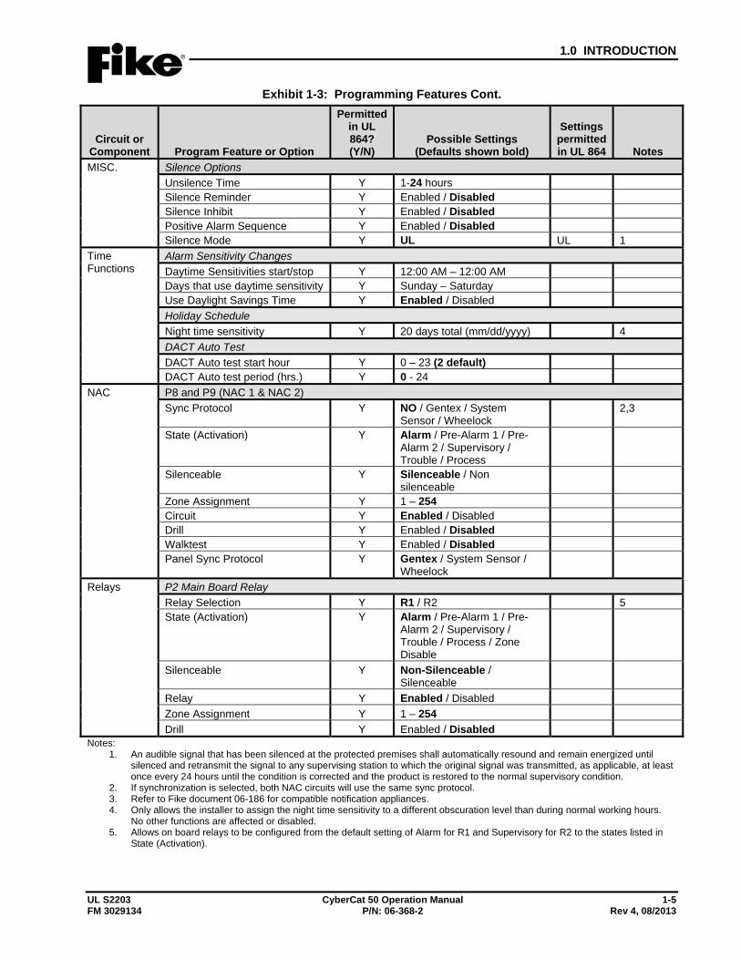
Exhibit 1-3: Programming Features Cont.
Circuit or Component Program Feature or Option
Permitted in UL 864? (Y/N)
Possible Settings (Defaults shown bold)
Settings permitted in UL 864 Notes
MISC. Silence Options Unsilence Time Y 1-24 hours Silence Reminder Y Enabled / Disabled Silence Inhibit Y Enabled / Disabled Positive Alarm Sequence Y Enabled / Disabled Silence Mode Y UL UL 1
Time Functions
Alarm Sensitivity Changes Daytime Sensitivities start/stop Y 12:00 AM – 12:00 AM Days that use daytime sensitivity Y Sunday – Saturday Use Daylight Savings Time Y Enabled / Disabled Holiday Schedule Night time sensitivity Y 20 days total (mm/dd/yyyy) 4 DACT Auto Test DACT Auto test start hour Y 0 – 23 (2 default) DACT Auto test period (hrs.) Y 0 - 24
NAC P8 and P9 (NAC 1 & NAC 2) Sync Protocol Y NO / Gentex / System
Sensor / Wheelock 2,3
State (Activation) Y Alarm / Pre-Alarm 1 / Pre-Alarm 2 / Supervisory / Trouble / Process
Silenceable Y Silenceable / Non silenceable
Zone Assignment Y 1 – 254 Circuit Y Enabled / Disabled Drill Y Enabled / Disabled Walktest Y Enabled / Disabled Panel Sync Protocol Y Gentex / System Sensor /
Wheelock
Relays P2 Main Board Relay Relay Selection Y R1 / R2 5 State (Activation) Y Alarm / Pre-Alarm 1 / Pre-
Alarm 2 / Supervisory / Trouble / Process / Zone Disable
Silenceable Y Non-Silenceable / Silenceable
Relay Y Enabled / Disabled Zone Assignment Y 1 – 254 Drill Y Enabled / Disabled
Notes: 1. An audible signal that has been silenced at the protected premises shall automatically resound and remain energized until
silenced and retransmit the signal to any supervising station to which the original signal was transmitted, as applicable, at least once every 24 hours until the condition is corrected and the product is restored to the normal supervisory condition.
2. If synchronization is selected, both NAC circuits will use the same sync protocol. 3. Refer to Fike document 06-186 for compatible notification appliances. 4. Only allows the installer to assign the night time sensitivity to a different obscuration level than during normal working hours.
No other functions are affected or disabled. 5. Allows on board relays to be configured from the default setting of Alarm for R1 and Supervisory for R2 to the states listed in
State (Activation).
1.0 INTRODUCTION
1-6 CyberCat 50 Operation Manual UL S2203 Rev 4, 08/2013 P/N: 06-368-2 FM 3029134
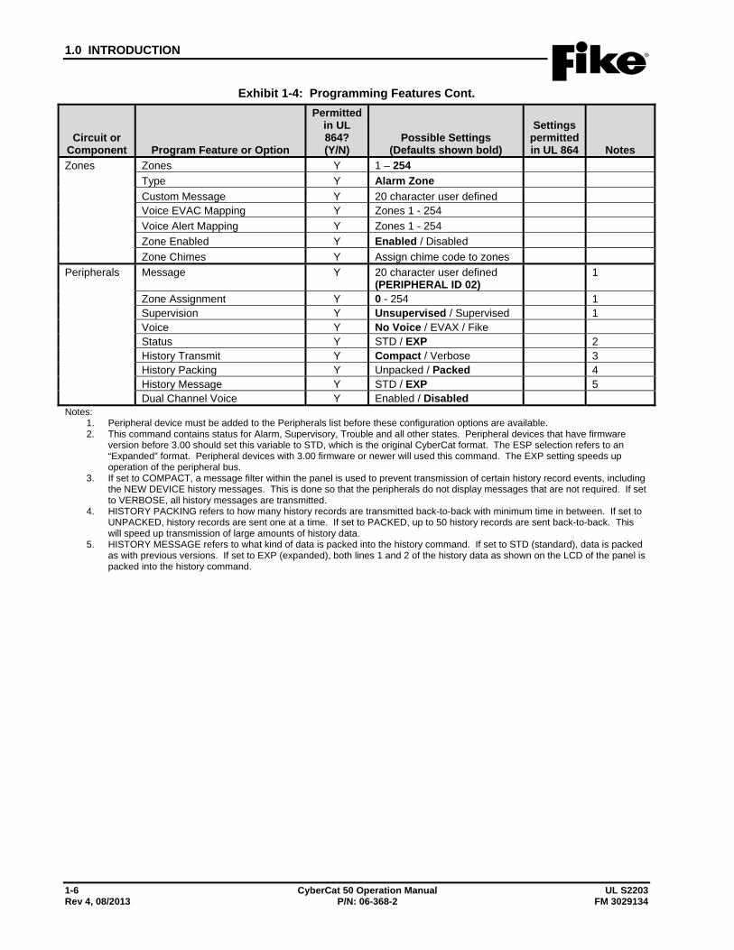
Exhibit 1-4: Programming Features Cont.
Circuit or Component Program Feature or Option
Permitted in UL 864? (Y/N)
Possible Settings (Defaults shown bold)
Settings permitted in UL 864 Notes
Zones Zones Y 1 – 254 Type Y Alarm Zone Custom Message Y 20 character user defined Voice EVAC Mapping Y Zones 1 - 254 Voice Alert Mapping Y Zones 1 - 254 Zone Enabled Y Enabled / Disabled Zone Chimes Y Assign chime code to zones
Peripherals Message Y 20 character user defined (PERIPHERAL ID 02)
1
Zone Assignment Y 0 - 254 1 Supervision Y Unsupervised / Supervised 1 Voice Y No Voice / EVAX / Fike Status Y STD / EXP 2 History Transmit Y Compact / Verbose 3 History Packing Y Unpacked / Packed 4 History Message Y STD / EXP 5 Dual Channel Voice Y Enabled / Disabled
Notes: 1. Peripheral device must be added to the Peripherals list before these configuration options are available. 2. This command contains status for Alarm, Supervisory, Trouble and all other states. Peripheral devices that have firmware
version before 3.00 should set this variable to STD, which is the original CyberCat format. The ESP selection refers to an “Expanded” format. Peripheral devices with 3.00 firmware or newer will used this command. The EXP setting speeds up operation of the peripheral bus.
3. If set to COMPACT, a message filter within the panel is used to prevent transmission of certain history record events, including the NEW DEVICE history messages. This is done so that the peripherals do not display messages that are not required. If set to VERBOSE, all history messages are transmitted.
4. HISTORY PACKING refers to how many history records are transmitted back-to-back with minimum time in between. If set to UNPACKED, history records are sent one at a time. If set to PACKED, up to 50 history records are sent back-to-back. This will speed up transmission of large amounts of history data.
5. HISTORY MESSAGE refers to what kind of data is packed into the history command. If set to STD (standard), data is packed as with previous versions. If set to EXP (expanded), both lines 1 and 2 of the history data as shown on the LCD of the panel is packed into the history command.
1.0 INTRODUCTION
UL S2203 CyberCat 50 Operation Manual 1-7 FM 3029134 P/N: 06-368-2 Rev 4, 08/2013
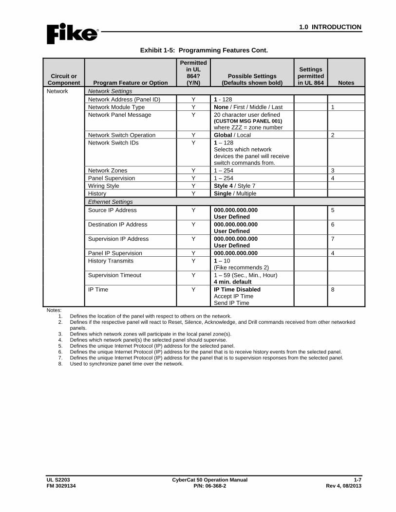
Exhibit 1-5: Programming Features Cont.
Circuit or Component Program Feature or Option
Permitted in UL 864? (Y/N)
Possible Settings (Defaults shown bold)
Settings permitted in UL 864 Notes
Network Network Settings Network Address (Panel ID) Y 1 - 128 Network Module Type Y None / First / Middle / Last 1 Network Panel Message Y 20 character user defined
(CUSTOM MSG PANEL 001) where ZZZ = zone number
Network Switch Operation Y Global / Local 2 Network Switch IDs Y 1 – 128
Selects which network devices the panel will receive switch commands from.
Network Zones Y 1 – 254 3 Panel Supervision Y 1 – 254 4 Wiring Style Y Style 4 / Style 7 History Y Single / Multiple Ethernet Settings Source IP Address Y 000.000.000.000
User Defined 5
Destination IP Address Y 000.000.000.000 User Defined
6
Supervision IP Address Y 000.000.000.000 User Defined
7
Panel IP Supervision Y 000.000.000.000 4 History Transmits Y 1 – 10
(Fike recommends 2)
Supervision Timeout Y 1 – 59 (Sec., Min., Hour) 4 min. default
IP Time Y IP Time Disabled Accept IP Time Send IP Time
8
Notes: 1. Defines the location of the panel with respect to others on the network. 2. Defines if the respective panel will react to Reset, Silence, Acknowledge, and Drill commands received from other networked
panels. 3. Defines which network zones will participate in the local panel zone(s). 4. Defines which network panel(s) the selected panel should supervise. 5. Defines the unique Internet Protocol (IP) address for the selected panel. 6. Defines the unique Internet Protocol (IP) address for the panel that is to receive history events from the selected panel. 7. Defines the unique Internet Protocol (IP) address for the panel that is to supervision responses from the selected panel. 8. Used to synchronize panel time over the network.
1.0 INTRODUCTION
1-8 CyberCat 50 Operation Manual UL S2203 Rev 4, 08/2013 P/N: 06-368-2 FM 3029134
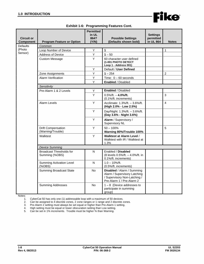
Exhibit 1-6: Programming Features Cont.
Circuit or Component Program Feature or Option
Permitted in UL 864? (Y/N)
Possible Settings (Defaults shown bold)
Settings permitted in UL 864 Notes
Defaults (Photo Sensor)
Common Loop Number of Device Y 1 1 Address of Device Y 1 – 50 Custom Message Y 60 character user defined
(1-001 PHOTO DETECT Loop 1 - Address 001)
Y Default / User Defined Zone Assignments Y 1 – 254 2 Alarm Verification Y Time: 0 – 60 seconds
Y Enabled / Disabled Sensitivity Pre-Alarm 1 & 2 Levels Y Enabled / Disabled
Y 0.5%/ft. – 4.0%/ft. (0.1%/ft. increments)
3
Alarm Levels Y Acclimate: 1.3%/ft. – 3.6%/ft.(High 2.0% - Low 2.5%)
4
Y Day/Night: 1.3%/ft. – 3.6%/ft.(Day 3.6% - Night 3.6%)
Y Alarm / Supervisory / Supervisory NL
Drift Compensation (Warning/Trouble)
Y 50 – 100% Warning 80%/Trouble 100%
5
Walktest Y Walktest at Alarm Level / Walktest with IR / Walktest at 1.3%
Device Summing Broadcast Thresholds for Summing (%OBS)
N Enabled / Disabled (8 levels 0.5%/ft. – 4.0%/ft. in 0.1%/ft. increments)
Summing Activation Level (%OBS)
N 1.0 – 10%/ft. (0.5%/ft. increments)
Summing Broadcast State No Disabled / Alarm / Summing Alarm / Supervisory Latching / Supervisory Non-Latching / Pre-Alarm 1 / Pre-Alarm 2
Summing Addresses No 1 – 8 (Device addresses to participate in summing group)
Notes: 1. CyberCat 50 has only one (1) addressable loop with a maximum of 50 devices. 2. Can be assigned to 4 discrete zones, 2 zone ranges or 1 range and 2 discrete zones. 3. Pre-Alarm 2 setting must always be set equal or higher than Pre-Alarm 1 setting. 4. High setting must be equal or lower obscuration setting than Low setting. 5. Can be set in 1% increments. Trouble must be higher % than Warning.
1.0 INTRODUCTION
UL S2203 CyberCat 50 Operation Manual 1-9 FM 3029134 P/N: 06-368-2 Rev 4, 08/2013
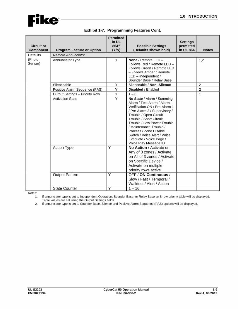
Exhibit 1-7: Programming Features Cont.
Circuit or Component Program Feature or Option
Permitted in UL 864? (Y/N)
Possible Settings (Defaults shown bold)
Settings permitted in UL 864 Notes
Defaults (Photo Sensor)
Remote Annunciator Annunciator Type Y None / Remote LED –
Follows Red / Remote LED – Follows Green / Remote LED – Follows Amber / Remote LED – Independent / Sounder Base / Relay Base
1,2
Silenceable Y Silenceable / Non- Silence 2 Positive Alarm Sequence (PAS) Y Disabled / Enabled 2 Output Settings – Priority Row Y 1 – 8 1 Activation State Y No State / Alarm / Summing
Alarm / Test Alarm / Alarm Verification ON / Pre-Alarm 1 / Pre-Alarm 2 / Supervisory / Trouble / Open Circuit Trouble / Short Circuit Trouble / Low Power Trouble / Maintenance Trouble / Process / Zone Disable Switch / Voice Alert / Voice Evacuate / Voice Page / Voice Play Message ID
Action Type Y No Action / Activate on Any of 3 zones / Activate on All of 3 zones / Activate on Specific Device / Activate on multiple priority rows active
Output Pattern Y OFF / ON Continuous / Slow / Fast / Temporal / Walktest / Alert / Action
State Counter Y 1 – 16 Notes:
1. If annunciator type is set to Independent Operation, Sounder Base, or Relay Base an 8-row priority table will be displayed. Table values are set using the Output Settings fields.
2. If annunciator type is set to Sounder Base, Silence and Positive Alarm Sequence (PAS) options will be displayed.
1.0 INTRODUCTION
1-10 CyberCat 50 Operation Manual UL S2203 Rev 4, 08/2013 P/N: 06-368-2 FM 3029134
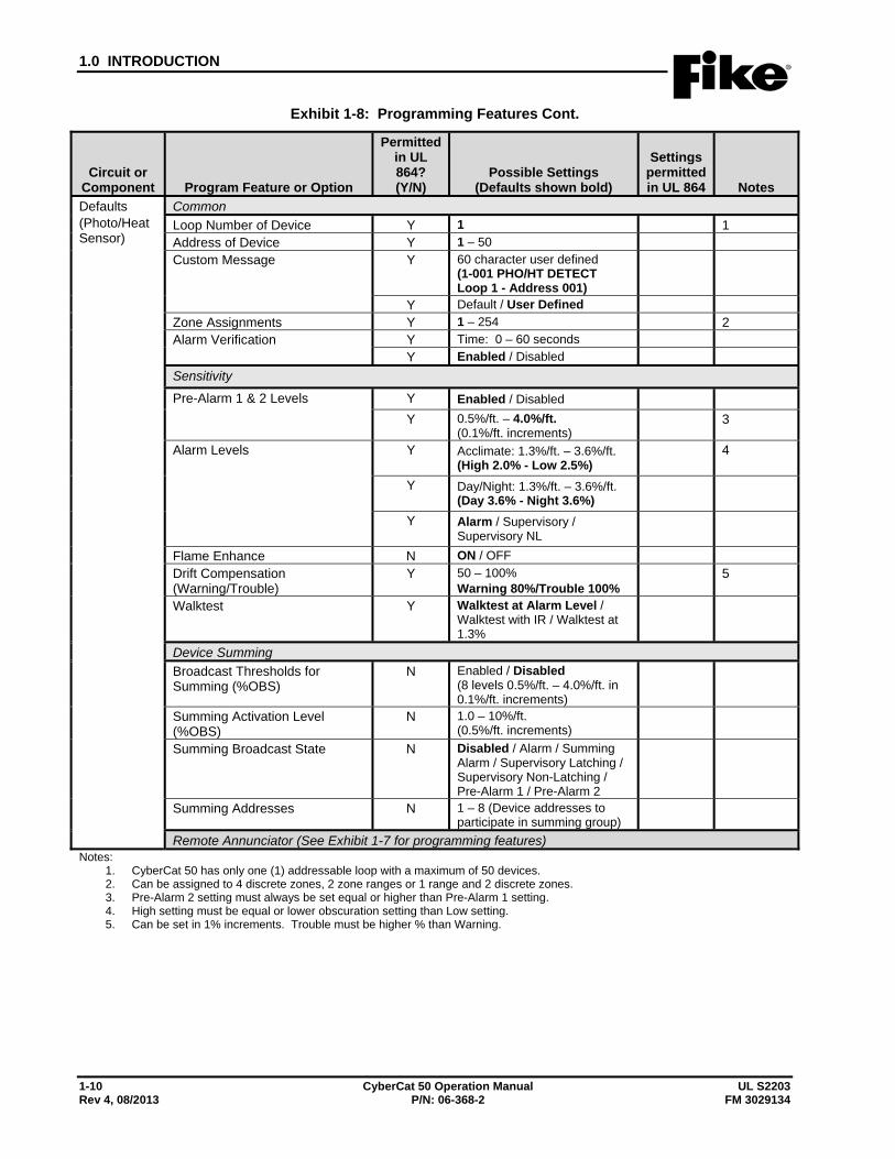
Exhibit 1-8: Programming Features Cont.
Circuit or Component Program Feature or Option
Permitted in UL 864? (Y/N)
Possible Settings (Defaults shown bold)
Settings permitted in UL 864 Notes
Defaults (Photo/Heat Sensor)
Common Loop Number of Device Y 1 1 Address of Device Y 1 – 50 Custom Message Y 60 character user defined
(1-001 PHO/HT DETECT Loop 1 - Address 001)
Y Default / User Defined Zone Assignments Y 1 – 254 2 Alarm Verification Y Time: 0 – 60 seconds
Y Enabled / Disabled Sensitivity
Pre-Alarm 1 & 2 Levels Y Enabled / Disabled Y 0.5%/ft. – 4.0%/ft.
(0.1%/ft. increments) 3
Alarm Levels Y Acclimate: 1.3%/ft. – 3.6%/ft. (High 2.0% - Low 2.5%)
4
Y Day/Night: 1.3%/ft. – 3.6%/ft. (Day 3.6% - Night 3.6%)
Y Alarm / Supervisory / Supervisory NL
Flame Enhance N ON / OFF Drift Compensation (Warning/Trouble)
Y 50 – 100% Warning 80%/Trouble 100%
5
Walktest Y Walktest at Alarm Level / Walktest with IR / Walktest at 1.3%
Device Summing Broadcast Thresholds for Summing (%OBS)
N Enabled / Disabled (8 levels 0.5%/ft. – 4.0%/ft. in 0.1%/ft. increments)
Summing Activation Level (%OBS)
N 1.0 – 10%/ft. (0.5%/ft. increments)
Summing Broadcast State N Disabled / Alarm / Summing Alarm / Supervisory Latching / Supervisory Non-Latching / Pre-Alarm 1 / Pre-Alarm 2
Summing Addresses N 1 – 8 (Device addresses to participate in summing group)
Remote Annunciator (See Exhibit 1-7 for programming features) Notes:
1. CyberCat 50 has only one (1) addressable loop with a maximum of 50 devices. 2. Can be assigned to 4 discrete zones, 2 zone ranges or 1 range and 2 discrete zones. 3. Pre-Alarm 2 setting must always be set equal or higher than Pre-Alarm 1 setting. 4. High setting must be equal or lower obscuration setting than Low setting. 5. Can be set in 1% increments. Trouble must be higher % than Warning.
1.0 INTRODUCTION
UL S2203 CyberCat 50 Operation Manual 1-11 FM 3029134 P/N: 06-368-2 Rev 4, 08/2013
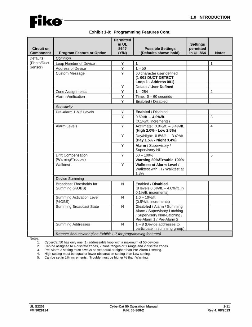
Exhibit 1-9: Programming Features Cont.
Circuit or Component Program Feature or Option
Permitted in UL 864? (Y/N)
Possible Settings (Defaults shown bold)
Settings permitted in UL 864 Notes
Defaults (Photo/Duct Sensor)
Common Loop Number of Device Y 1 1 Address of Device Y 1 – 50 Custom Message Y 60 character user defined
(1-001 DUCT DETECT Loop 1 - Address 001)
Y Default / User Defined Zone Assignments Y 1 – 254 2 Alarm Verification Y Time: 0 – 60 seconds
Y Enabled / Disabled Sensitivity Pre-Alarm 1 & 2 Levels Y Enabled / Disabled
Y 0.6%/ft. – 4.0%/ft. (0.1%/ft. increments)
3
Alarm Levels Y Acclimate: 0.8%/ft. – 3.4%/ft. (High 2.0% - Low 2.5%)
4
Y Day/Night: 0.8%/ft. – 3.4%/ft. (Day 1.5% - Night 3.4%)
Y Alarm / Supervisory / Supervisory NL
Drift Compensation (Warning/Trouble)
Y 50 – 100% Warning 80%/Trouble 100%
5
Walktest Y Walktest at Alarm Level / Walktest with IR / Walktest at 1.3%
Device Summing Broadcast Thresholds for Summing (%OBS)
N Enabled / Disabled (8 levels 0.5%/ft. – 4.0%/ft. in 0.1%/ft. increments)
Summing Activation Level (%OBS)
N 1.0 – 10%/ft. (0.5%/ft. increments)
Summing Broadcast State N Disabled / Alarm / Summing Alarm / Supervisory Latching / Supervisory Non-Latching / Pre-Alarm 1 / Pre-Alarm 2
Summing Addresses N 1 – 8 (Device addresses to participate in summing group)
Remote Annunciator (See Exhibit 1-7 for programming features) Notes:
1. CyberCat 50 has only one (1) addressable loop with a maximum of 50 devices. 2. Can be assigned to 4 discrete zones, 2 zone ranges or 1 range and 2 discrete zones. 3. Pre-Alarm 2 setting must always be set equal or higher than Pre-Alarm 1 setting. 4. High setting must be equal or lower obscuration setting than Low setting. 5. Can be set in 1% increments. Trouble must be higher % than Warning.
1.0 INTRODUCTION
1-12 CyberCat 50 Operation Manual UL S2203 Rev 4, 08/2013 P/N: 06-368-2 FM 3029134
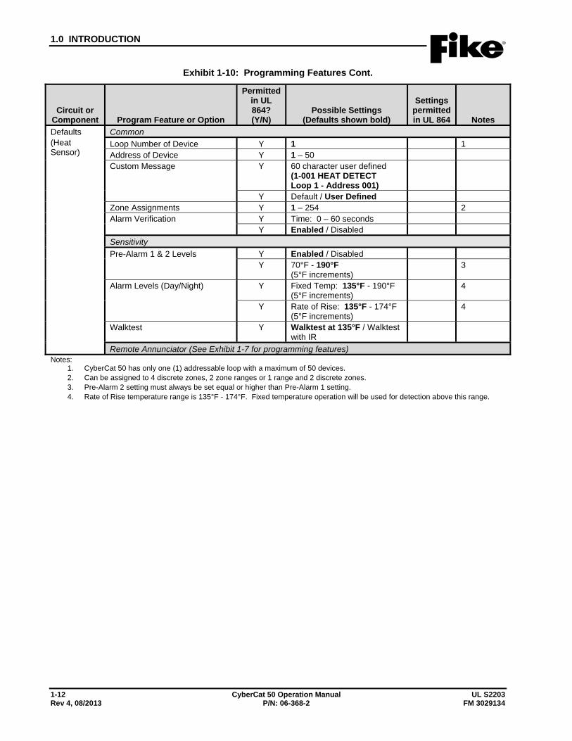
Exhibit 1-10: Programming Features Cont.
Circuit or Component Program Feature or Option
Permitted in UL 864? (Y/N)
Possible Settings (Defaults shown bold)
Settings permitted in UL 864 Notes
Defaults (Heat Sensor)
Common Loop Number of Device Y 1 1 Address of Device Y 1 – 50 Custom Message Y 60 character user defined
(1-001 HEAT DETECT Loop 1 - Address 001)
Y Default / User Defined Zone Assignments Y 1 – 254 2 Alarm Verification Y Time: 0 – 60 seconds
Y Enabled / Disabled Sensitivity Pre-Alarm 1 & 2 Levels Y Enabled / Disabled
Y 70°F - 190°F (5°F increments)
3
Alarm Levels (Day/Night) Y Fixed Temp: 135°F - 190°F (5°F increments)
4
Y Rate of Rise: 135°F - 174°F (5°F increments)
4
Walktest Y Walktest at 135°F / Walktest with IR
Remote Annunciator (See Exhibit 1-7 for programming features) Notes:
1. CyberCat 50 has only one (1) addressable loop with a maximum of 50 devices. 2. Can be assigned to 4 discrete zones, 2 zone ranges or 1 range and 2 discrete zones. 3. Pre-Alarm 2 setting must always be set equal or higher than Pre-Alarm 1 setting. 4. Rate of Rise temperature range is 135°F - 174°F. Fixed temperature operation will be used for detection above this range.
1.0 INTRODUCTION
UL S2203 CyberCat 50 Operation Manual 1-13 FM 3029134 P/N: 06-368-2 Rev 4, 08/2013
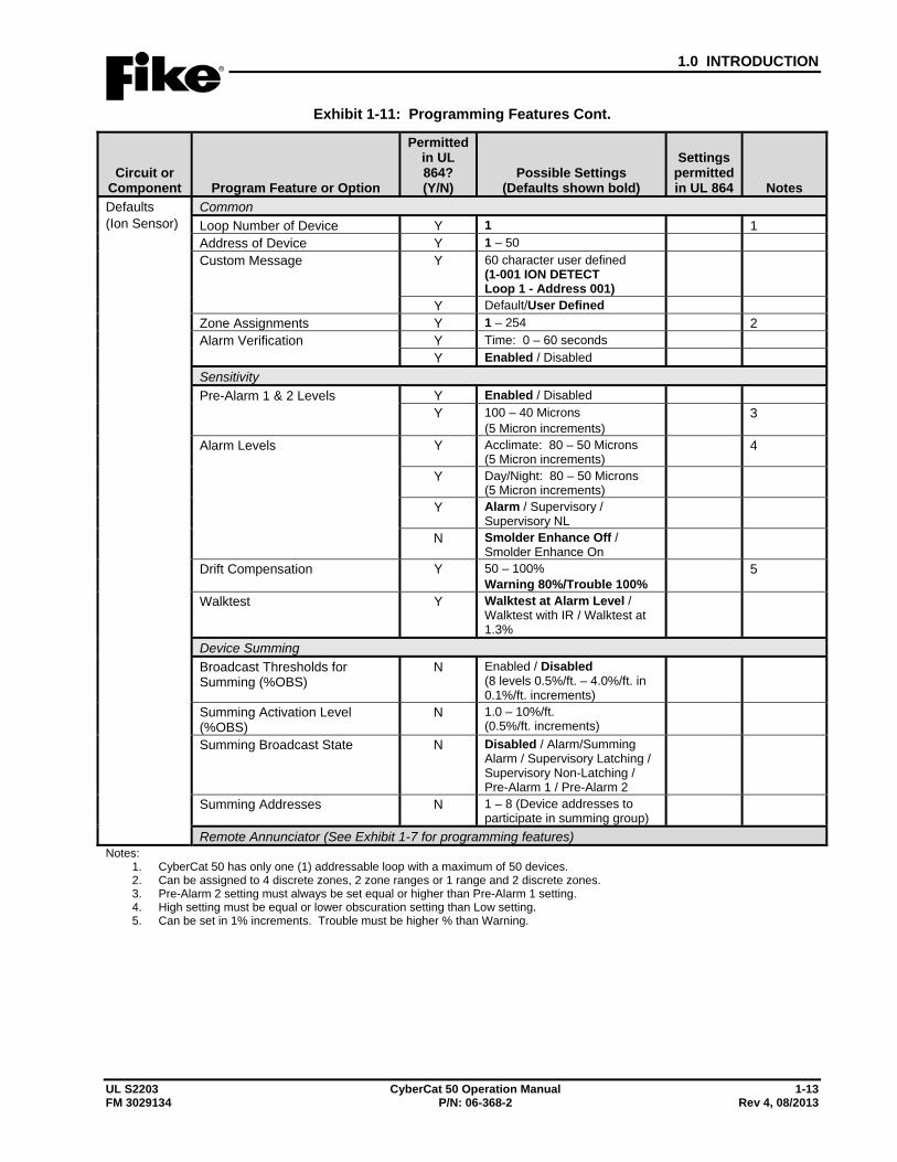
Exhibit 1-11: Programming Features Cont.
Circuit or Component Program Feature or Option
Permitted in UL 864? (Y/N)
Possible Settings (Defaults shown bold)
Settings permitted in UL 864 Notes
Defaults (Ion Sensor)
Common Loop Number of Device Y 1 1 Address of Device Y 1 – 50 Custom Message Y 60 character user defined
(1-001 ION DETECT Loop 1 - Address 001)
Y Default/User Defined Zone Assignments Y 1 – 254 2 Alarm Verification Y Time: 0 – 60 seconds
Y Enabled / Disabled Sensitivity Pre-Alarm 1 & 2 Levels Y Enabled / Disabled
Y 100 – 40 Microns (5 Micron increments)
3
Alarm Levels Y Acclimate: 80 – 50 Microns (5 Micron increments)
4
Y Day/Night: 80 – 50 Microns (5 Micron increments)
Y Alarm / Supervisory / Supervisory NL
N Smolder Enhance Off / Smolder Enhance On
Drift Compensation Y 50 – 100% Warning 80%/Trouble 100%
5
Walktest Y Walktest at Alarm Level / Walktest with IR / Walktest at 1.3%
Device Summing Broadcast Thresholds for Summing (%OBS)
N Enabled / Disabled (8 levels 0.5%/ft. – 4.0%/ft. in 0.1%/ft. increments)
Summing Activation Level (%OBS)
N 1.0 – 10%/ft. (0.5%/ft. increments)
Summing Broadcast State N Disabled / Alarm/Summing Alarm / Supervisory Latching / Supervisory Non-Latching / Pre-Alarm 1 / Pre-Alarm 2
Summing Addresses N 1 – 8 (Device addresses to participate in summing group)
Remote Annunciator (See Exhibit 1-7 for programming features) Notes:
1. CyberCat 50 has only one (1) addressable loop with a maximum of 50 devices. 2. Can be assigned to 4 discrete zones, 2 zone ranges or 1 range and 2 discrete zones. 3. Pre-Alarm 2 setting must always be set equal or higher than Pre-Alarm 1 setting. 4. High setting must be equal or lower obscuration setting than Low setting. 5. Can be set in 1% increments. Trouble must be higher % than Warning.
1.0 INTRODUCTION
1-14 CyberCat 50 Operation Manual UL S2203 Rev 4, 08/2013 P/N: 06-368-2 FM 3029134
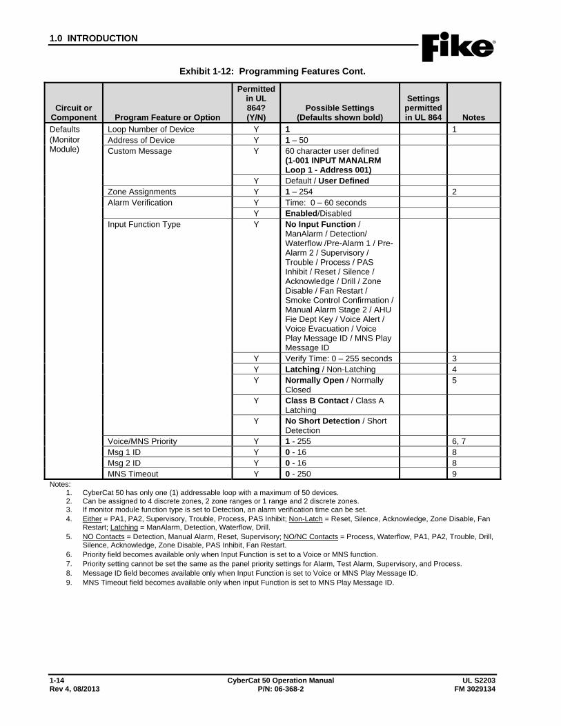
Exhibit 1-12: Programming Features Cont.
Circuit or Component Program Feature or Option
Permitted in UL 864? (Y/N)
Possible Settings (Defaults shown bold)
Settings permitted in UL 864 Notes
Defaults (Monitor Module)
Loop Number of Device Y 1 1 Address of Device Y 1 – 50 Custom Message Y 60 character user defined
(1-001 INPUT MANALRM Loop 1 - Address 001)
Y Default / User Defined Zone Assignments Y 1 – 254 2 Alarm Verification Y Time: 0 – 60 seconds
Y Enabled/Disabled Input Function Type Y No Input Function /
ManAlarm / Detection/ Waterflow /Pre-Alarm 1 / Pre-Alarm 2 / Supervisory / Trouble / Process / PAS Inhibit / Reset / Silence / Acknowledge / Drill / Zone Disable / Fan Restart / Smoke Control Confirmation / Manual Alarm Stage 2 / AHU Fie Dept Key / Voice Alert / Voice Evacuation / Voice Play Message ID / MNS Play Message ID
Y Verify Time: 0 – 255 seconds 3 Y Latching / Non-Latching 4 Y Normally Open / Normally
Closed 5
Y Class B Contact / Class A Latching
Y No Short Detection / Short Detection
Voice/MNS Priority Y 1 - 255 6, 7 Msg 1 ID Y 0 - 16 8 Msg 2 ID Y 0 - 16 8 MNS Timeout Y 0 - 250 9
Notes: 1. CyberCat 50 has only one (1) addressable loop with a maximum of 50 devices. 2. Can be assigned to 4 discrete zones, 2 zone ranges or 1 range and 2 discrete zones. 3. If monitor module function type is set to Detection, an alarm verification time can be set. 4. Either = PA1, PA2, Supervisory, Trouble, Process, PAS Inhibit; Non-Latch = Reset, Silence, Acknowledge, Zone Disable, Fan
Restart; Latching = ManAlarm, Detection, Waterflow, Drill. 5. NO Contacts = Detection, Manual Alarm, Reset, Supervisory; NO/NC Contacts = Process, Waterflow, PA1, PA2, Trouble, Drill,
Silence, Acknowledge, Zone Disable, PAS Inhibit, Fan Restart. 6. Priority field becomes available only when Input Function is set to a Voice or MNS function. 7. Priority setting cannot be set the same as the panel priority settings for Alarm, Test Alarm, Supervisory, and Process. 8. Message ID field becomes available only when Input Function is set to Voice or MNS Play Message ID. 9. MNS Timeout field becomes available only when input Function is set to MNS Play Message ID.
1.0 INTRODUCTION
UL S2203 CyberCat 50 Operation Manual 1-15 FM 3029134 P/N: 06-368-2 Rev 4, 08/2013
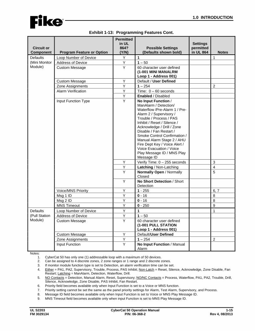
Exhibit 1-13: Programming Features Cont.
Circuit or Component Program Feature or Option
Permitted in UL 864? (Y/N)
Possible Settings (Defaults shown bold)
Settings permitted in UL 864 Notes
Defaults (Mini Monitor Module)
Loop Number of Device Y 1 1 Address of Device Y 1 – 50 Custom Message Y 60 character user defined
(1-001 MINI MANALRM Loop 1 - Address 001)
Custom Message Y Default / User Defined Zone Assignments Y 1 – 254 2 Alarm Verification Y Time: 0 – 60 seconds
Y Enabled / Disabled Input Function Type Y No Input Function /
ManAlarm / Detection/ Waterflow /Pre-Alarm 1 / Pre-Alarm 2 / Supervisory / Trouble / Process / PAS Inhibit / Reset / Silence / Acknowledge / Drill / Zone Disable / Fan Restart / Smoke Control Confirmation / Manual Alarm Stage 2 / AHU Fire Dept Key / Voice Alert / Voice Evacuation / Voice Play Message ID / MNS Play Message ID
Y Verify Time: 0 – 255 seconds 3 Y Latching / Non-Latching 4 Y Normally Open / Normally
Closed 5
Y No Short Detection / Short Detection
Voice/MNS Priority Y 1 - 255 6, 7 Msg 1 ID Y 0 - 16 8 Msg 2 ID Y 0 - 16 8 MNS Timeout Y 0 - 250 9
Defaults (Pull Station Module)
Loop Number of Device Y 1 1 Address of Device Y 1 – 50 Custom Message Y 60 character user defined
(1-001 PULL STATION Loop 1 - Address 001)
Custom Message Y Default/User Defined Zone Assignments Y 1 – 254 2 Input Function Y No Input Function / Manual
Alarm
Notes: 1. CyberCat 50 has only one (1) addressable loop with a maximum of 50 devices. 2. Can be assigned to 4 discrete zones, 2 zone ranges or 1 range and 2 discrete zones. 3. If monitor module function type is set to Detection, an alarm verification time can be set. 4. Either = PA1, PA2, Supervisory, Trouble, Process, PAS Inhibit; Non-Latch = Reset, Silence, Acknowledge, Zone Disable, Fan
Restart; Latching = ManAlarm, Detection, Waterflow, Drill. 5. NO Contacts = Detection, Manual Alarm, Reset, Supervisory; NO/NC Contacts = Process, Waterflow, PA1, PA2, Trouble, Drill,
Silence, Acknowledge, Zone Disable, PAS Inhibit, Fan Restart. 6. Priority field becomes available only when Input Function is set to a Voice or MNS function. 7. Priority setting cannot be set the same as the panel priority settings for Alarm, Test Alarm, Supervisory, and Process. 8. Message ID field becomes available only when Input Function is set to Voice or MNS Play Message ID. 9. MNS Timeout field becomes available only when input Function is set to MNS Play Message ID.
1.0 INTRODUCTION
1-16 CyberCat 50 Operation Manual UL S2203 Rev 4, 08/2013 P/N: 06-368-2 FM 3029134
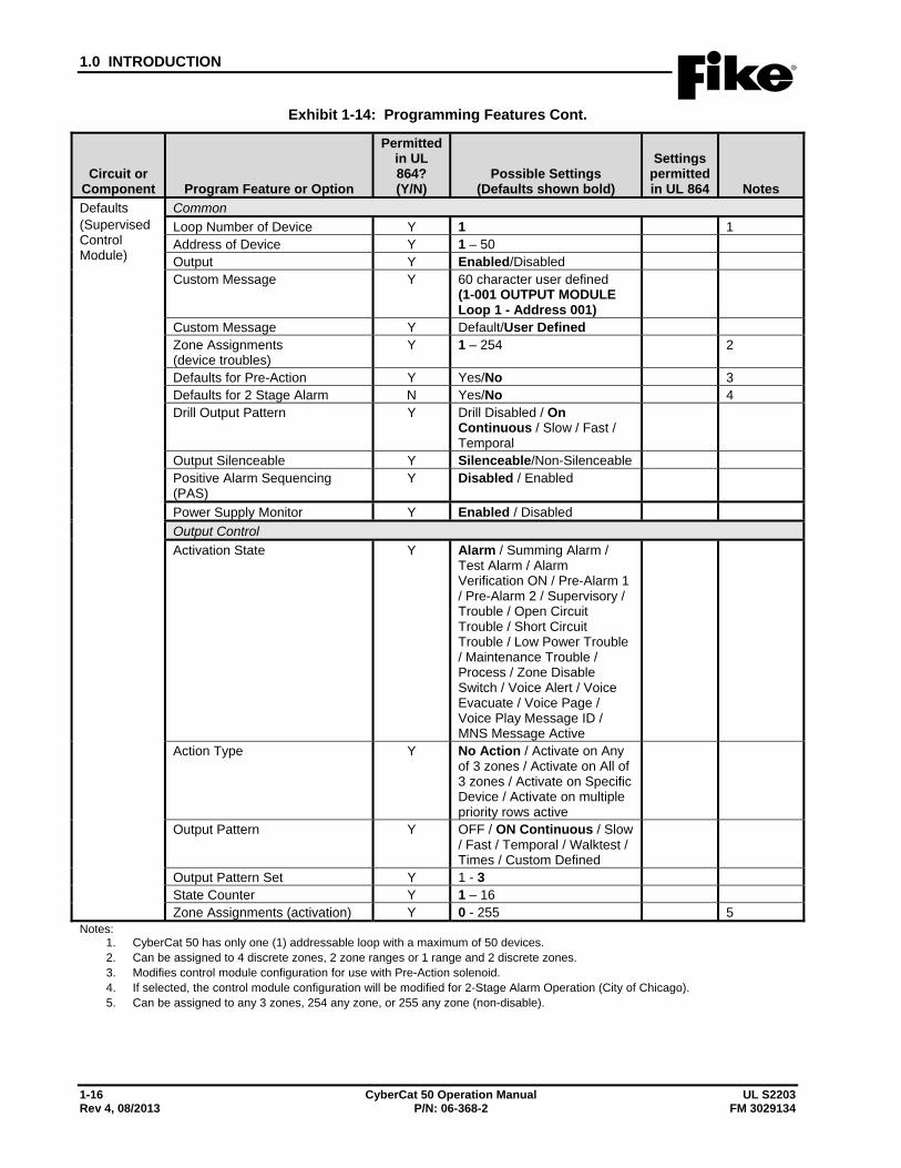
Exhibit 1-14: Programming Features Cont.
Circuit or Component Program Feature or Option
Permitted in UL 864? (Y/N)
Possible Settings (Defaults shown bold)
Settings permitted in UL 864 Notes
Defaults (Supervised Control Module)
Common Loop Number of Device Y 1 1 Address of Device Y 1 – 50 Output Y Enabled/Disabled Custom Message Y 60 character user defined
(1-001 OUTPUT MODULE Loop 1 - Address 001)
Custom Message Y Default/User Defined Zone Assignments (device troubles)
Y 1 – 254 2
Defaults for Pre-Action Y Yes/No 3 Defaults for 2 Stage Alarm N Yes/No 4 Drill Output Pattern Y Drill Disabled / On
Continuous / Slow / Fast / Temporal
Output Silenceable Y Silenceable/Non-Silenceable Positive Alarm Sequencing (PAS)
Y Disabled / Enabled
Power Supply Monitor Y Enabled / Disabled Output Control Activation State Y Alarm / Summing Alarm /
Test Alarm / Alarm Verification ON / Pre-Alarm 1 / Pre-Alarm 2 / Supervisory / Trouble / Open Circuit Trouble / Short Circuit Trouble / Low Power Trouble / Maintenance Trouble / Process / Zone Disable Switch / Voice Alert / Voice Evacuate / Voice Page / Voice Play Message ID / MNS Message Active
Action Type Y No Action / Activate on Any of 3 zones / Activate on All of 3 zones / Activate on Specific Device / Activate on multiple priority rows active
Output Pattern Y OFF / ON Continuous / Slow / Fast / Temporal / Walktest / Times / Custom Defined
Output Pattern Set Y 1 - 3 State Counter Y 1 – 16 Zone Assignments (activation) Y 0 - 255 5
Notes: 1. CyberCat 50 has only one (1) addressable loop with a maximum of 50 devices. 2. Can be assigned to 4 discrete zones, 2 zone ranges or 1 range and 2 discrete zones. 3. Modifies control module configuration for use with Pre-Action solenoid. 4. If selected, the control module configuration will be modified for 2-Stage Alarm Operation (City of Chicago). 5. Can be assigned to any 3 zones, 254 any zone, or 255 any zone (non-disable).
1.0 INTRODUCTION
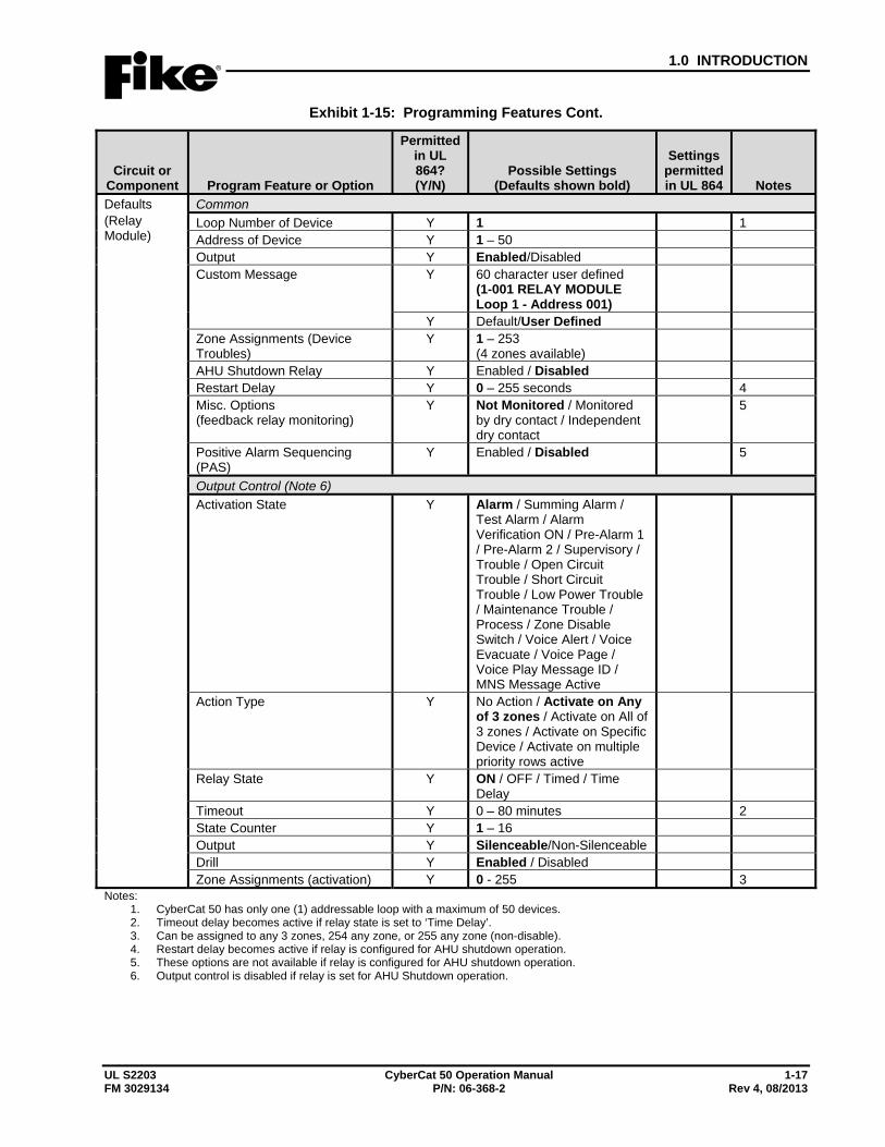
UL S2203 CyberCat 50 Operation Manual 1-17 FM 3029134 P/N: 06-368-2 Rev 4, 08/2013
Exhibit 1-15: Programming Features Cont.
Circuit or Component Program Feature or Option
Permitted in UL 864? (Y/N)
Possible Settings (Defaults shown bold)
Settings permitted in UL 864 Notes
Defaults (Relay Module)
Common Loop Number of Device Y 1 1 Address of Device Y 1 – 50 Output Y Enabled/Disabled Custom Message Y 60 character user defined
(1-001 RELAY MODULE Loop 1 - Address 001)
Y Default/User Defined Zone Assignments (Device Troubles)
Y 1 – 253 (4 zones available)
AHU Shutdown Relay Y Enabled / Disabled Restart Delay Y 0 – 255 seconds 4 Misc. Options (feedback relay monitoring)
Y Not Monitored / Monitored by dry contact / Independent dry contact
5
Positive Alarm Sequencing (PAS)
Y Enabled / Disabled 5
Output Control (Note 6) Activation State Y Alarm / Summing Alarm /
Test Alarm / Alarm Verification ON / Pre-Alarm 1 / Pre-Alarm 2 / Supervisory / Trouble / Open Circuit Trouble / Short Circuit Trouble / Low Power Trouble / Maintenance Trouble / Process / Zone Disable Switch / Voice Alert / Voice Evacuate / Voice Page / Voice Play Message ID / MNS Message Active
Action Type Y No Action / Activate on Any of 3 zones / Activate on All of 3 zones / Activate on Specific Device / Activate on multiple priority rows active
Relay State Y ON / OFF / Timed / Time Delay
Timeout Y 0 – 80 minutes 2 State Counter Y 1 – 16 Output Y Silenceable/Non-Silenceable Drill Y Enabled / Disabled Zone Assignments (activation) Y 0 - 255 3
Notes: 1. CyberCat 50 has only one (1) addressable loop with a maximum of 50 devices. 2. Timeout delay becomes active if relay state is set to ‘Time Delay’. 3. Can be assigned to any 3 zones, 254 any zone, or 255 any zone (non-disable). 4. Restart delay becomes active if relay is configured for AHU shutdown operation. 5. These options are not available if relay is configured for AHU shutdown operation. 6. Output control is disabled if relay is set for AHU Shutdown operation.
1.0 INTRODUCTION
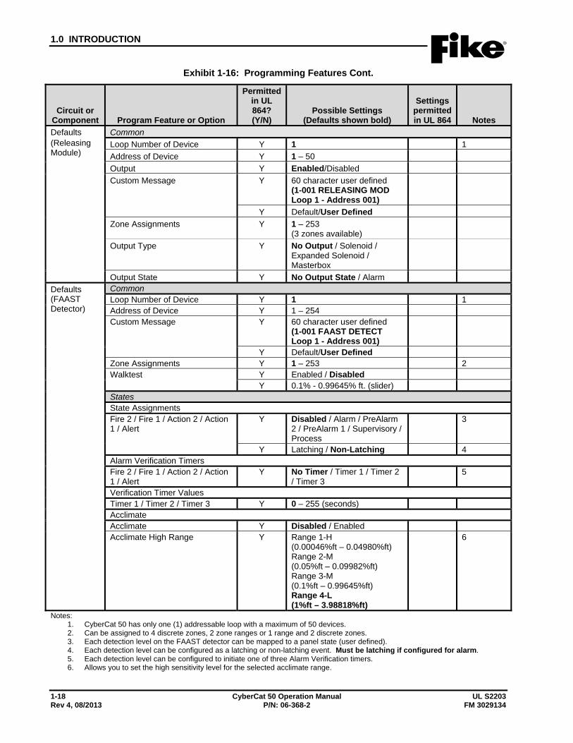
1-18 CyberCat 50 Operation Manual UL S2203 Rev 4, 08/2013 P/N: 06-368-2 FM 3029134
Exhibit 1-16: Programming Features Cont.
Circuit or Component Program Feature or Option
Permitted in UL 864? (Y/N)
Possible Settings (Defaults shown bold)
Settings permitted in UL 864 Notes
Defaults (Releasing Module)
Common Loop Number of Device Y 1 1 Address of Device Y 1 – 50 Output Y Enabled/Disabled Custom Message Y 60 character user defined
(1-001 RELEASING MOD Loop 1 - Address 001)
Y Default/User Defined Zone Assignments Y 1 – 253
(3 zones available)
Output Type Y No Output / Solenoid / Expanded Solenoid / Masterbox
Output State Y No Output State / Alarm Defaults (FAAST Detector)
Common Loop Number of Device Y 1 1 Address of Device Y 1 – 254 Custom Message Y 60 character user defined
(1-001 FAAST DETECT Loop 1 - Address 001)
Y Default/User Defined Zone Assignments Y 1 – 253 2 Walktest Y Enabled / Disabled
Y 0.1% - 0.99645% ft. (slider) States State Assignments Fire 2 / Fire 1 / Action 2 / Action 1 / Alert
Y Disabled / Alarm / PreAlarm 2 / PreAlarm 1 / Supervisory / Process
3
Y Latching / Non-Latching 4 Alarm Verification Timers Fire 2 / Fire 1 / Action 2 / Action 1 / Alert
Y No Timer / Timer 1 / Timer 2 / Timer 3
5
Verification Timer Values Timer 1 / Timer 2 / Timer 3 Y 0 – 255 (seconds) Acclimate Acclimate Y Disabled / Enabled Acclimate High Range Y Range 1-H
(0.00046%ft – 0.04980%ft) Range 2-M (0.05%ft – 0.09982%ft) Range 3-M (0.1%ft – 0.99645%ft) Range 4-L (1%ft – 3.98818%ft)
6
Notes: 1. CyberCat 50 has only one (1) addressable loop with a maximum of 50 devices. 2. Can be assigned to 4 discrete zones, 2 zone ranges or 1 range and 2 discrete zones. 3. Each detection level on the FAAST detector can be mapped to a panel state (user defined). 4. Each detection level can be configured as a latching or non-latching event. Must be latching if configured for alarm. 5. Each detection level can be configured to initiate one of three Alarm Verification timers. 6. Allows you to set the high sensitivity level for the selected acclimate range.
1.0 INTRODUCTION
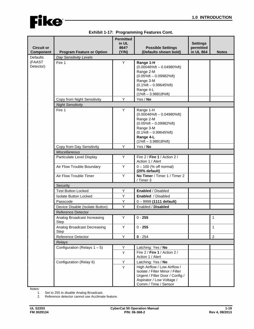
UL S2203 CyberCat 50 Operation Manual 1-19 FM 3029134 P/N: 06-368-2 Rev 4, 08/2013
Exhibit 1-17: Programming Features Cont.
Circuit or Component Program Feature or Option
Permitted in UL 864? (Y/N)
Possible Settings (Defaults shown bold)
Settings permitted in UL 864 Notes
Defaults (FAAST Detector)
Day Sensitivity Levels Fire 1 Y Range 1-H
(0.00046%ft – 0.04980%ft) Range 2-M (0.05%ft – 0.09982%ft) Range 3-M (0.1%ft – 0.99645%ft) Range 4-L (1%ft – 3.98818%ft)
Copy from Night Sensitivity Y Yes / No Night Sensitivity Fire 1 Y Range 1-H
(0.00046%ft – 0.04980%ft) Range 2-M (0.05%ft – 0.09982%ft) Range 3-M (0.1%ft – 0.99645%ft) Range 4-L (1%ft – 3.98818%ft)
Copy from Day Sensitivity Y Yes / No Miscellaneous Particulate Level Display Y Fire 2 / Fire 1 / Action 2 /
Action 1 / Alert
Air Flow Trouble Boundary Y 0 – 100 (% off normal) (20% default)
Air Flow Trouble Timer Y No Timer / Timer 1 / Timer 2 / Timer 3
Security Test Button Locked Y Enabled / Disabled Isolate Button Locked Y Enabled / Disabled Passcode Y 0 – 9999 (1111 default) Device Disable (Isolate Button) Y Enabled / Disabled Reference Detector Analog Broadcast Increasing Step
Y 0 - 255 1
Analog Broadcast Decreasing Step
Y 0 - 255 1
Reference Detector Y 0 - 254 2 Relays Configuration (Relays 1 – 5) Y Latching: Yes / No
Y Fire 2 / Fire 1 / Action 2 / Action 1 / Alert
Configuration (Relay 6) Y Latching: Yes / No Y High Airflow / Low Airflow /
Isolate / Filter Minor / Filter Urgent / Filter Door / Config / Aspirator / Low Voltage / Comm / Time / Sensor
Notes: 1. Set to 255 to disable Analog Broadcast. 2. Reference detector cannot use Acclimate feature.
1.0 INTRODUCTION
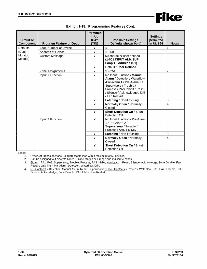
1-20 CyberCat 50 Operation Manual UL S2203 Rev 4, 08/2013 P/N: 06-368-2 FM 3029134
Exhibit 1-18: Programming Features Cont.
Circuit or Component Program Feature or Option
Permitted in UL 864? (Y/N)
Possible Settings (Defaults shown bold)
Settings permitted in UL 864 Notes
Defaults (Dual Monitor Module)
Loop Number of Device Y 1 1 Address of Device Y 1 – 50 Custom Message Y 60 character user defined
(1-001 INPUT ALM/SUP Loop 1 - Address 001)
Y Default / User Defined Zone Assignments Y 1 – 254 2 Input 1 Function Y No Input Function / Manual
Alarm / Detection/ Waterflow /Pre-Alarm 1 / Pre-Alarm 2 / Supervisory / Trouble / Process / PAS Inhibit / Reset / Silence / Acknowledge / Drill / Fan Restart
Y Latching / Non-Latching 3 Y Normally Open / Normally
Closed 4
Y Short Detection On / Short Detection Off
Input 2 Function Y No Input Function / Pre-Alarm 1 / Pre-Alarm 2 / Supervisory / Trouble / Process / AHU FD Key
Y Latching / Non-Latching 3 Y Normally Open / Normally
Closed 4
Y Short Detection On / Short Detection Off
Notes: 1. CyberCat 50 has only one (1) addressable loop with a maximum of 50 devices. 2. Can be assigned to 4 discrete zones, 2 zone ranges or 1 range and 2 discrete zones. 3. Either = PA1, PA2, Supervisory, Trouble, Process, PAS Inhibit; Non-Latch = Reset, Silence, Acknowledge, Zone Disable, Fan
Restart; Latching = ManAlarm, Detection, Waterflow, Drill. 4. NO Contacts = Detection, Manual Alarm, Reset, Supervisory; NO/NC Contacts = Process, Waterflow, PA1, PA2, Trouble, Drill,
Silence, Acknowledge, Zone Disable, PAS Inhibit, Fan Restart.
1.0 INTRODUCTION
UL S2203 CyberCat 50 Operation Manual 1-21 FM 3029134 P/N: 06-368-2 Rev 4, 08/2013
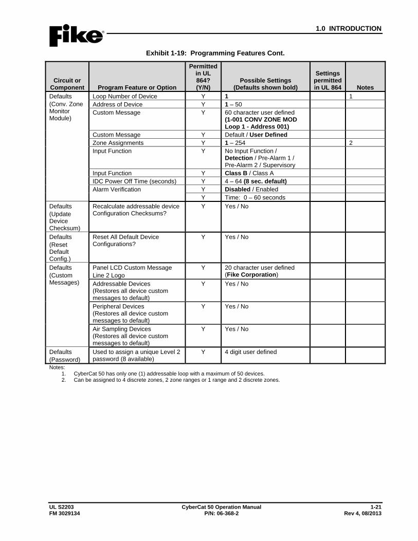
Exhibit 1-19: Programming Features Cont.
Circuit or Component Program Feature or Option
Permitted in UL 864? (Y/N)
Possible Settings (Defaults shown bold)
Settings permitted in UL 864 Notes
Defaults (Conv. Zone Monitor Module)
Loop Number of Device Y 1 1 Address of Device Y 1 – 50 Custom Message Y 60 character user defined
(1-001 CONV ZONE MOD Loop 1 - Address 001)
Custom Message Y Default / User Defined Zone Assignments Y 1 – 254 2 Input Function Y No Input Function /
Detection / Pre-Alarm 1 / Pre-Alarm 2 / Supervisory
Input Function Y Class B / Class A IDC Power Off Time (seconds) Y 4 – 64 (8 sec. default) Alarm Verification Y Disabled / Enabled
Y Time: 0 – 60 seconds Defaults (Update Device Checksum)
Recalculate addressable device Configuration Checksums?
Y Yes / No
Defaults (Reset Default Config.)
Reset All Default Device Configurations?
Y Yes / No
Defaults (Custom Messages)
Panel LCD Custom Message Line 2 Logo
Y 20 character user defined (Fike Corporation)
Addressable Devices (Restores all device custom messages to default)
Y Yes / No
Peripheral Devices (Restores all device custom messages to default)
Y Yes / No
Air Sampling Devices (Restores all device custom messages to default)
Y Yes / No
Defaults (Password)
Used to assign a unique Level 2 password (8 available)
Y 4 digit user defined
Notes: 1. CyberCat 50 has only one (1) addressable loop with a maximum of 50 devices. 2. Can be assigned to 4 discrete zones, 2 zone ranges or 1 range and 2 discrete zones.

1.0 INTRODUCTION
1-22 CyberCat 50 Operation Manual UL S2203 Rev 4, 08/2013 P/N: 06-368-2 FM 3029134
Exhibit 1-20: Programming Features Cont.
Circuit or Component Program Feature or Option
Permitted in UL 864? (Y/N)
Possible Settings (Defaults shown bold)
Settings permitted in UL 864 Notes
Peripheral Device Configuration Options Remote Display 14 Key
Address Y 2 - 32 Custom Message Y 20 character user defined
(Fike Remote Display)
Corporate Logo Y 20 character user defined (Fike Corporation)
Buzzer Operation Y Enabled / Disabled Network History Display Y Show All History / Filter
History by Zone
Countdown Display Y Show Countdown Display / Show Release Imminent
Countdown Filter Y Show All Zone Countdowns / Filter Countdown by Zone / Do not show Countdown
Programmable Key Functions (1 – 8)
Y NO Function / Reset / Silence / Acknowledge / Drill / Process / Walktest / IR Tool / Step Alarm / Step Supervisory / Step Trouble / Step All / Fan Restart / Zone Disable
1
Remote Display 2 and 10 Key
Address Y 2 - 32 Custom Message Y 20 character user defined
(Fike Remote Display)
Corporate Logo Y 20 character user defined (Fike Corporation)
Buzzer Operation Y Enabled / Disabled Network History Display Y Show All History / Filter
History by Zone
Countdown Display Y Show Countdown Display / Show Release Imminent
Countdown Filter Y Show All Zone Countdowns / Filter Countdown by Zone / Do not show Countdown
Notes: 1. Process and Zone Disable will require a zone number be assigned (1 – 253).
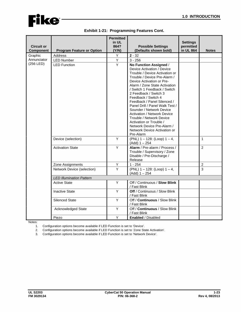
1.0 INTRODUCTION
UL S2203 CyberCat 50 Operation Manual 1-23 FM 3029134 P/N: 06-368-2 Rev 4, 08/2013
Exhibit 1-21: Programming Features Cont.
Circuit or Component Program Feature or Option
Permitted in UL 864? (Y/N)
Possible Settings (Defaults shown bold)
Settings permitted in UL 864 Notes
Graphic Annunciator (256 LED)
Address Y 2 - 32 LED Number Y 3 - 256 LED Function Y No Function Assigned /
Device Activation / Device Trouble / Device Activation or Trouble / Device Pre-Alarm / Device Activation or Pre-Alarm / Zone State Activation / Switch 1 Feedback / Switch 2 Feedback / Switch 3 Feedback / Switch 4 Feedback / Panel Silenced / Panel Drill / Panel Walk Test / Sounder / Network Device Activation / Network Device Trouble / Network Device Activation or Trouble / Network Device Pre-Alarm / Network Device Activation or Pre-Alarm
Device (selection) Y (PNL) 1 – 128: (Loop) 1 – 4, (Add) 1 – 254
1
Activation State Y Alarm / Pre-alarm / Process / Trouble / Supervisory / Zone Disable / Pre-Discharge / Release
2
Zone Assignments Y 1 - 254 2 Network Device (selection) Y (PNL) 1 – 128: (Loop) 1 – 4,
(Add) 1 – 254 3
LED Illumination Pattern Active State Y Off / Continuous / Slow Blink
/ Fast Blink
Inactive State Y Off / Continuous / Slow Blink / Fast Blink
Silenced State Y Off / Continuous / Slow Blink / Fast Blink
Acknowledged State Y Off / Continuous / Slow Blink / Fast Blink
Piezo Y Enabled / Disabled Notes:
1. Configuration options become available if LED Function is set to ‘Device’. 2. Configuration options become available if LED Function is set to ‘Zone State Activation’. 3. Configuration options become available if LED Function is set to ‘Network Device’.
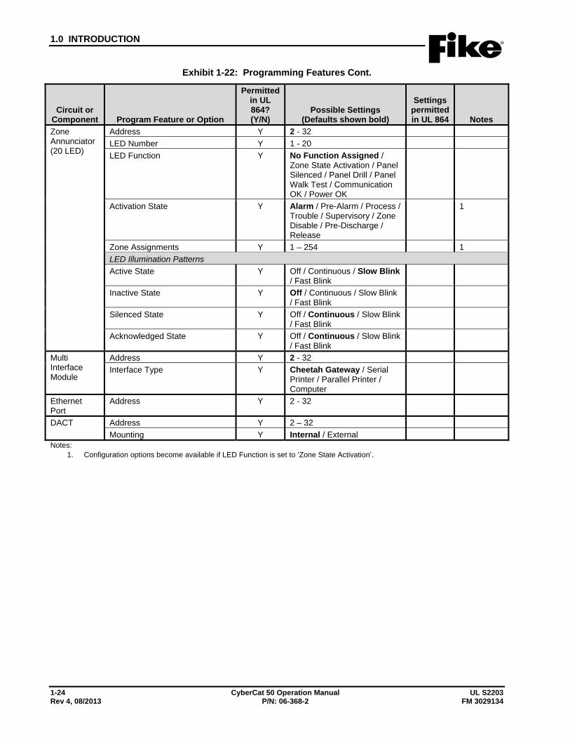
1.0 INTRODUCTION
1-24 CyberCat 50 Operation Manual UL S2203 Rev 4, 08/2013 P/N: 06-368-2 FM 3029134
Exhibit 1-22: Programming Features Cont.
Circuit or Component Program Feature or Option
Permitted in UL 864? (Y/N)
Possible Settings (Defaults shown bold)
Settings permitted in UL 864 Notes
Zone Annunciator (20 LED)
Address Y 2 - 32 LED Number Y 1 - 20 LED Function Y No Function Assigned /
Zone State Activation / Panel Silenced / Panel Drill / Panel Walk Test / Communication OK / Power OK
Activation State Y Alarm / Pre-Alarm / Process / Trouble / Supervisory / Zone Disable / Pre-Discharge / Release
1
Zone Assignments Y 1 – 254 1 LED Illumination Patterns Active State Y Off / Continuous / Slow Blink
/ Fast Blink
Inactive State Y Off / Continuous / Slow Blink / Fast Blink
Silenced State Y Off / Continuous / Slow Blink / Fast Blink
Acknowledged State Y Off / Continuous / Slow Blink / Fast Blink
Multi Interface Module
Address Y 2 - 32 Interface Type Y Cheetah Gateway / Serial
Printer / Parallel Printer / Computer
Ethernet Port
Address Y 2 - 32
DACT Address Y 2 – 32 Mounting Y Internal / External
Notes: 1. Configuration options become available if LED Function is set to ‘Zone State Activation’.
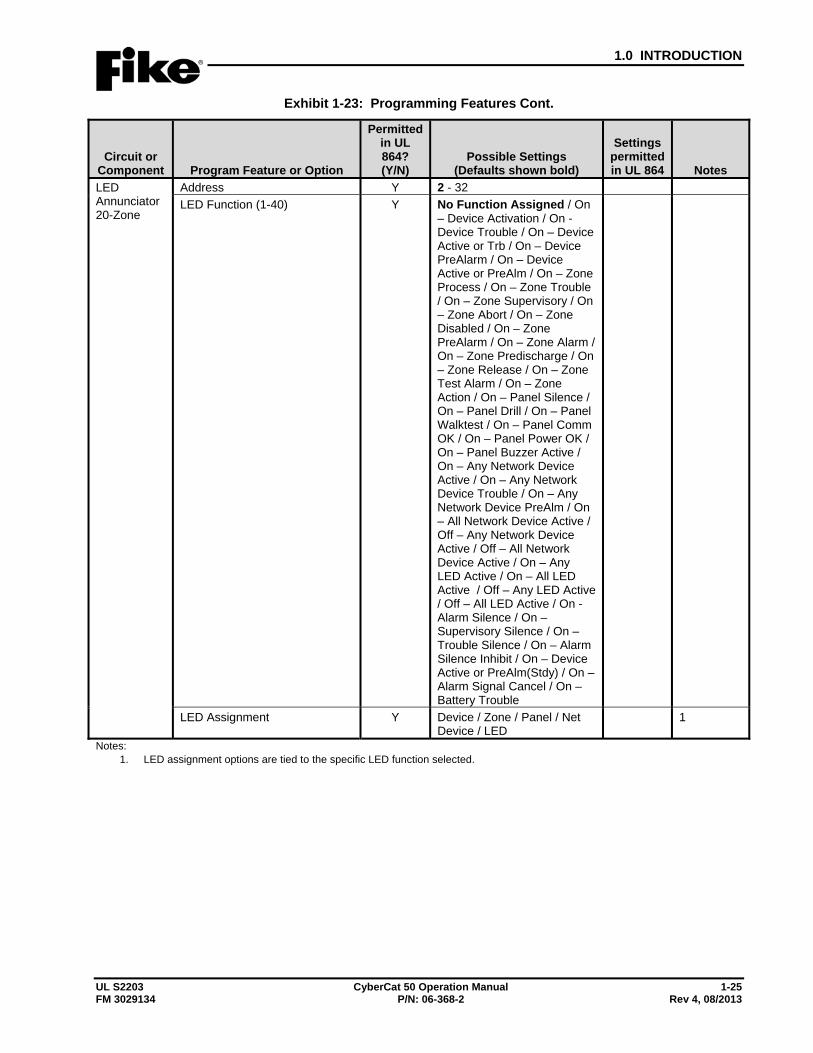
1.0 INTRODUCTION
UL S2203 CyberCat 50 Operation Manual 1-25 FM 3029134 P/N: 06-368-2 Rev 4, 08/2013
Exhibit 1-23: Programming Features Cont.
Circuit or Component Program Feature or Option
Permitted in UL 864? (Y/N)
Possible Settings (Defaults shown bold)
Settings permitted in UL 864 Notes
LED Annunciator 20-Zone
Address Y 2 - 32 LED Function (1-40) Y No Function Assigned / On
– Device Activation / On - Device Trouble / On – Device Active or Trb / On – Device PreAlarm / On – Device Active or PreAlm / On – Zone Process / On – Zone Trouble / On – Zone Supervisory / On – Zone Abort / On – Zone Disabled / On – Zone PreAlarm / On – Zone Alarm / On – Zone Predischarge / On – Zone Release / On – Zone Test Alarm / On – Zone Action / On – Panel Silence / On – Panel Drill / On – Panel Walktest / On – Panel Comm OK / On – Panel Power OK / On – Panel Buzzer Active / On – Any Network Device Active / On – Any Network Device Trouble / On – Any Network Device PreAlm / On – All Network Device Active / Off – Any Network Device Active / Off – All Network Device Active / On – Any LED Active / On – All LED Active / Off – Any LED Active / Off – All LED Active / On - Alarm Silence / On – Supervisory Silence / On – Trouble Silence / On – Alarm Silence Inhibit / On – Device Active or PreAlm(Stdy) / On – Alarm Signal Cancel / On – Battery Trouble
LED Assignment Y Device / Zone / Panel / Net Device / LED
1
Notes: 1. LED assignment options are tied to the specific LED function selected.
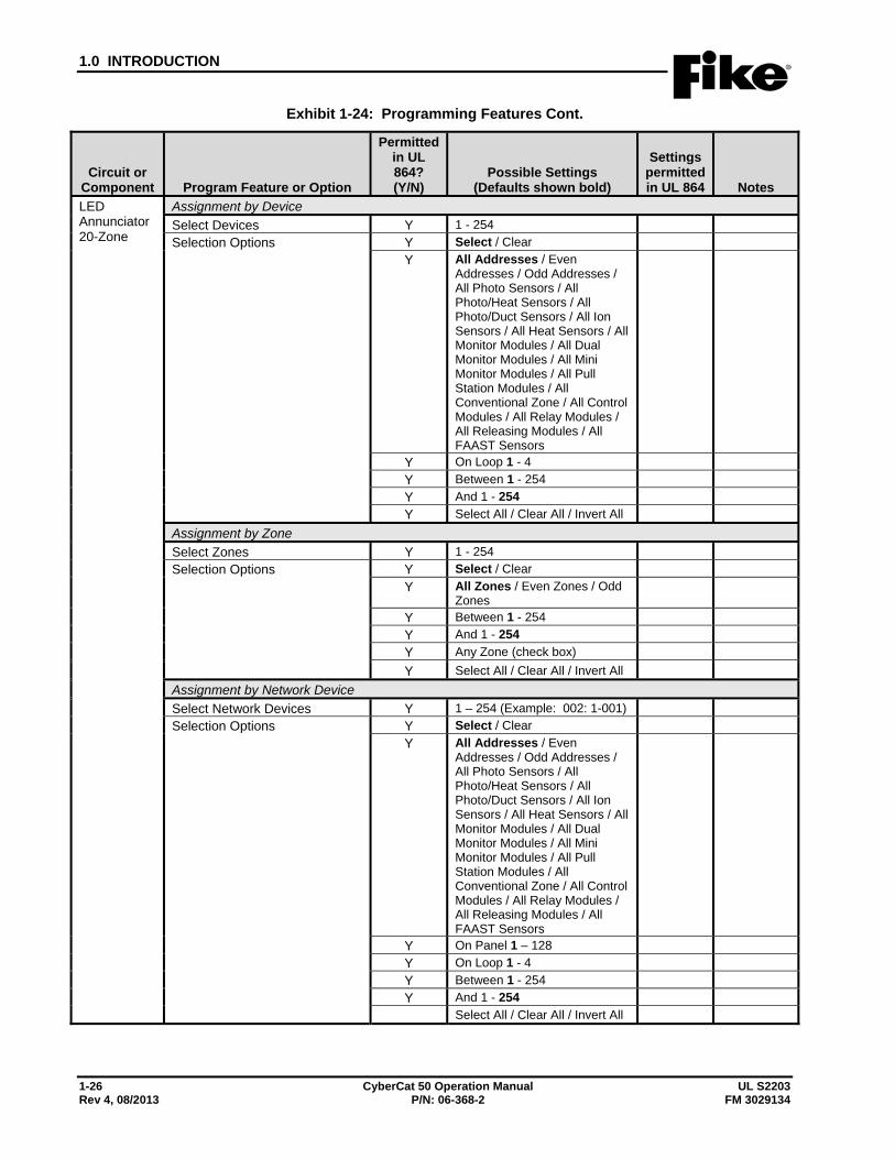
1.0 INTRODUCTION
1-26 CyberCat 50 Operation Manual UL S2203 Rev 4, 08/2013 P/N: 06-368-2 FM 3029134
Exhibit 1-24: Programming Features Cont.
Circuit or Component Program Feature or Option
Permitted in UL 864? (Y/N)
Possible Settings (Defaults shown bold)
Settings permitted in UL 864 Notes
LED Annunciator 20-Zone
Assignment by Device Select Devices Y 1 - 254 Selection Options Y Select / Clear
Y All Addresses / Even Addresses / Odd Addresses / All Photo Sensors / All Photo/Heat Sensors / All Photo/Duct Sensors / All Ion Sensors / All Heat Sensors / All Monitor Modules / All Dual Monitor Modules / All Mini Monitor Modules / All Pull Station Modules / All Conventional Zone / All Control Modules / All Relay Modules / All Releasing Modules / All FAAST Sensors
Y On Loop 1 - 4 Y Between 1 - 254 Y And 1 - 254 Y Select All / Clear All / Invert All
Assignment by Zone Select Zones Y 1 - 254 Selection Options Y Select / Clear
Y All Zones / Even Zones / Odd Zones
Y Between 1 - 254 Y And 1 - 254 Y Any Zone (check box) Y Select All / Clear All / Invert All
Assignment by Network Device Select Network Devices Y 1 – 254 (Example: 002: 1-001) Selection Options Y Select / Clear
Y All Addresses / Even Addresses / Odd Addresses / All Photo Sensors / All Photo/Heat Sensors / All Photo/Duct Sensors / All Ion Sensors / All Heat Sensors / All Monitor Modules / All Dual Monitor Modules / All Mini Monitor Modules / All Pull Station Modules / All Conventional Zone / All Control Modules / All Relay Modules / All Releasing Modules / All FAAST Sensors
Y On Panel 1 – 128 Y On Loop 1 - 4 Y Between 1 - 254 Y And 1 - 254 Select All / Clear All / Invert All
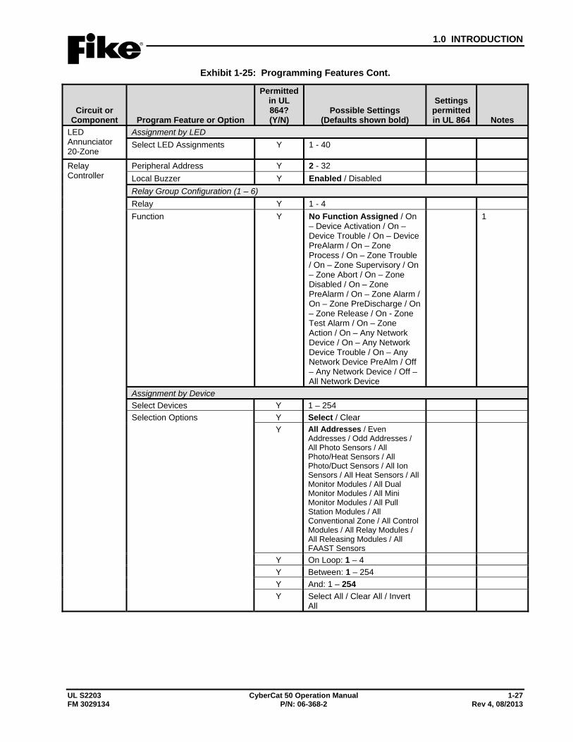
1.0 INTRODUCTION
UL S2203 CyberCat 50 Operation Manual 1-27 FM 3029134 P/N: 06-368-2 Rev 4, 08/2013
Exhibit 1-25: Programming Features Cont.
Circuit or Component Program Feature or Option
Permitted in UL 864? (Y/N)
Possible Settings (Defaults shown bold)
Settings permitted in UL 864 Notes
LED Annunciator 20-Zone
Assignment by LED Select LED Assignments Y 1 - 40
Relay Controller
Peripheral Address Y 2 - 32 Local Buzzer Y Enabled / Disabled Relay Group Configuration (1 – 6) Relay Y 1 - 4 Function Y No Function Assigned / On
– Device Activation / On – Device Trouble / On – Device PreAlarm / On – Zone Process / On – Zone Trouble / On – Zone Supervisory / On – Zone Abort / On – Zone Disabled / On – Zone PreAlarm / On – Zone Alarm / On – Zone PreDischarge / On – Zone Release / On - Zone Test Alarm / On – Zone Action / On – Any Network Device / On – Any Network Device Trouble / On – Any Network Device PreAlm / Off – Any Network Device / Off – All Network Device
1
Assignment by Device Select Devices Y 1 – 254 Selection Options Y Select / Clear
Y All Addresses / Even Addresses / Odd Addresses / All Photo Sensors / All Photo/Heat Sensors / All Photo/Duct Sensors / All Ion Sensors / All Heat Sensors / All Monitor Modules / All Dual Monitor Modules / All Mini Monitor Modules / All Pull Station Modules / All Conventional Zone / All Control Modules / All Relay Modules / All Releasing Modules / All FAAST Sensors
Y On Loop: 1 – 4 Y Between: 1 – 254 Y And: 1 – 254 Y Select All / Clear All / Invert
All
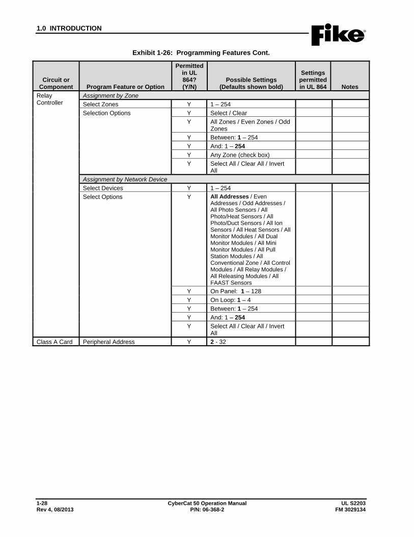
1.0 INTRODUCTION
1-28 CyberCat 50 Operation Manual UL S2203 Rev 4, 08/2013 P/N: 06-368-2 FM 3029134
Exhibit 1-26: Programming Features Cont.
Circuit or Component Program Feature or Option
Permitted in UL 864? (Y/N)
Possible Settings (Defaults shown bold)
Settings permitted in UL 864 Notes
Relay Controller
Assignment by Zone Select Zones Y 1 – 254 Selection Options Y Select / Clear
Y All Zones / Even Zones / Odd Zones
Y Between: 1 – 254 Y And: 1 – 254 Y Any Zone (check box) Y Select All / Clear All / Invert
All
Assignment by Network Device Select Devices Y 1 – 254 Select Options Y All Addresses / Even
Addresses / Odd Addresses / All Photo Sensors / All Photo/Heat Sensors / All Photo/Duct Sensors / All Ion Sensors / All Heat Sensors / All Monitor Modules / All Dual Monitor Modules / All Mini Monitor Modules / All Pull Station Modules / All Conventional Zone / All Control Modules / All Relay Modules / All Releasing Modules / All FAAST Sensors
Y On Panel: 1 – 128 Y On Loop: 1 – 4 Y Between: 1 – 254 Y And: 1 – 254 Y Select All / Clear All / Invert
All
Class A Card Peripheral Address Y 2 - 32
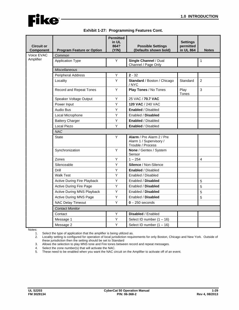
1.0 INTRODUCTION
UL S2203 CyberCat 50 Operation Manual 1-29 FM 3029134 P/N: 06-368-2 Rev 4, 08/2013
Exhibit 1-27: Programming Features Cont.
Circuit or Component Program Feature or Option
Permitted in UL 864? (Y/N)
Possible Settings (Defaults shown bold)
Settings permitted in UL 864 Notes
Voice EVAC Amplifier
Common Application Type Y Single Channel / Dual
Channel / Page Only 1
Miscellaneous Peripheral Address Y 2 - 32 Locality Y Standard / Boston / Chicago
/ NYC Standard 2
Record and Repeat Tones Y Play Tones / No Tones Play Tones
3
Speaker Voltage Output Y 25 VAC / 70.7 VAC Power Input Y 120 VAC / 240 VAC Audio Bus Y Enabled / Disabled Local Microphone Y Enabled / Disabled Battery Charger Y Enabled / Disabled Local Piezo Y Enabled / Disabled NAC State Y Alarm / Pre Alarm 2 / Pre
Alarm 1 / Supervisory / Trouble / Process
Synchronization Y None / Gentex / System Sensor
Zones Y 1 – 254 4 Silenceable Y Silence / Non-Silence Drill Y Enabled / Disabled Walk Test Y Enabled / Disabled Active During Fire Playback Y Enabled / Disabled 5 Active During Fire Page Y Enabled / Disabled 5 Active During MNS Playback Y Enabled / Disabled 5 Active During MNS Page Y Enabled / Disabled 5 NAC Delay Timeout Y 0 – 250 seconds Contact Monitor Contact Y Disabled / Enabled Message 1 Y Select ID number (1 – 16) Message 2 Y Select ID number (1 – 16)
Notes: 1. Select the type of application that the amplifier is being utilized as. 2. Locality setting is configured for operation of local jurisdiction requirements for only Boston, Chicago and New York. Outside of
these jurisdiction then the setting should be set to Standard 3. Allows the selection to play MNS tone and Fire tones between record and repeat messages. 4. Select the zone number(s) that will activate the NAC. 5. These need to be enabled when you want the NAC circuit on the Amplifier to activate off of an event.
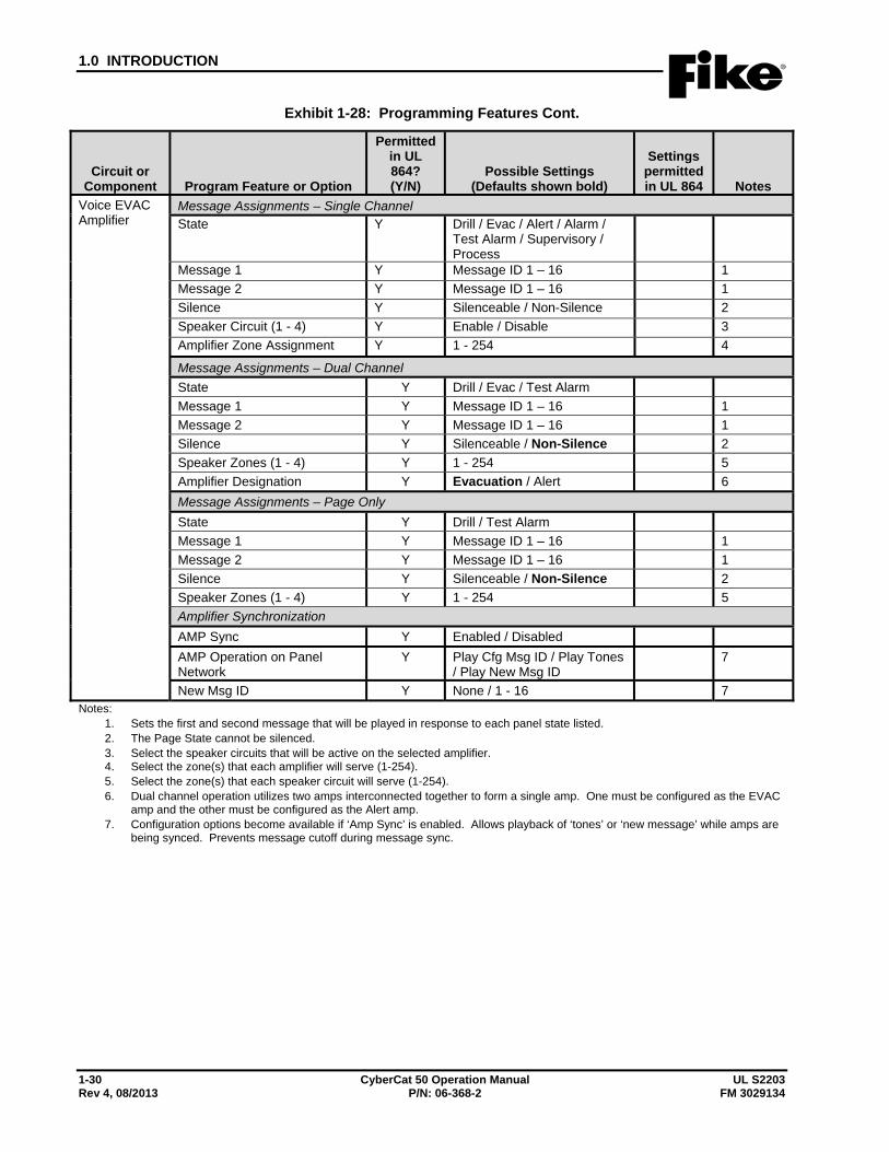
1.0 INTRODUCTION
1-30 CyberCat 50 Operation Manual UL S2203 Rev 4, 08/2013 P/N: 06-368-2 FM 3029134
Exhibit 1-28: Programming Features Cont.
Circuit or Component Program Feature or Option
Permitted in UL 864? (Y/N)
Possible Settings (Defaults shown bold)
Settings permitted in UL 864 Notes
Voice EVAC Amplifier
Message Assignments – Single Channel State Y Drill / Evac / Alert / Alarm /
Test Alarm / Supervisory / Process
Message 1 Y Message ID 1 – 16 1 Message 2 Y Message ID 1 – 16 1 Silence Y Silenceable / Non-Silence 2 Speaker Circuit (1 - 4) Y Enable / Disable 3 Amplifier Zone Assignment Y 1 - 254 4
Message Assignments – Dual Channel State Y Drill / Evac / Test Alarm Message 1 Y Message ID 1 – 16 1 Message 2 Y Message ID 1 – 16 1 Silence Y Silenceable / Non-Silence 2 Speaker Zones (1 - 4) Y 1 - 254 5 Amplifier Designation Y Evacuation / Alert 6 Message Assignments – Page Only State Y Drill / Test Alarm Message 1 Y Message ID 1 – 16 1 Message 2 Y Message ID 1 – 16 1 Silence Y Silenceable / Non-Silence 2 Speaker Zones (1 - 4) Y 1 - 254 5 Amplifier Synchronization AMP Sync Y Enabled / Disabled AMP Operation on Panel Network
Y Play Cfg Msg ID / Play Tones / Play New Msg ID
7
New Msg ID Y None / 1 - 16 7 Notes:
1. Sets the first and second message that will be played in response to each panel state listed. 2. The Page State cannot be silenced. 3. Select the speaker circuits that will be active on the selected amplifier. 4. Select the zone(s) that each amplifier will serve (1-254). 5. Select the zone(s) that each speaker circuit will serve (1-254). 6. Dual channel operation utilizes two amps interconnected together to form a single amp. One must be configured as the EVAC
amp and the other must be configured as the Alert amp. 7. Configuration options become available if ‘Amp Sync’ is enabled. Allows playback of ‘tones’ or ‘new message’ while amps are
being synced. Prevents message cutoff during message sync.
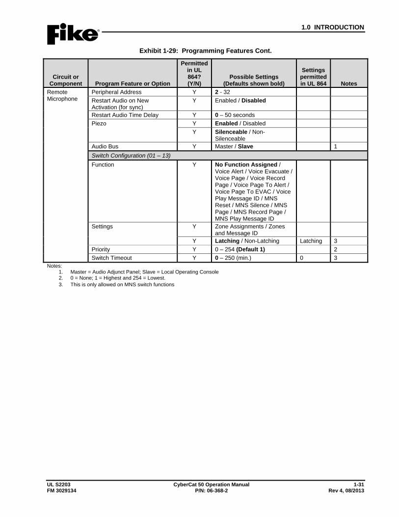
1.0 INTRODUCTION
UL S2203 CyberCat 50 Operation Manual 1-31 FM 3029134 P/N: 06-368-2 Rev 4, 08/2013
Exhibit 1-29: Programming Features Cont.
Circuit or Component Program Feature or Option
Permitted in UL 864? (Y/N)
Possible Settings (Defaults shown bold)
Settings permitted in UL 864 Notes
Remote Microphone
Peripheral Address Y 2 - 32 Restart Audio on New Activation (for sync)
Y Enabled / Disabled
Restart Audio Time Delay Y 0 – 50 seconds Piezo Y Enabled / Disabled
Y Silenceable / Non-Silenceable
Audio Bus Y Master / Slave 1 Switch Configuration (01 – 13) Function Y No Function Assigned /
Voice Alert / Voice Evacuate / Voice Page / Voice Record Page / Voice Page To Alert / Voice Page To EVAC / Voice Play Message ID / MNS Reset / MNS Silence / MNS Page / MNS Record Page / MNS Play Message ID
Settings Y Zone Assignments / Zones and Message ID
Y Latching / Non-Latching Latching 3 Priority Y 0 – 254 (Default 1) 2 Switch Timeout Y 0 – 250 (min.) 0 3
Notes: 1. Master = Audio Adjunct Panel; Slave = Local Operating Console 2. 0 = None; 1 = Highest and 254 = Lowest. 3. This is only allowed on MNS switch functions

1.0 INTRODUCTION
1-32 CyberCat 50 Operation Manual UL S2203 Rev 4, 08/2013 P/N: 06-368-2 FM 3029134
Exhibit 1-30: Programming Features Cont.
Circuit or Component Program Feature or Option
Permitted in UL 864? (Y/N)
Possible Settings (Defaults shown bold)
Settings permitted in UL 864 Notes
Air Sampling Detectors Configuration Options VESDA Compact, Laser Focus, and Laser Plus
VESDA Zone Number Y 1 – 254 State Y Alarm / Supervisory /
Trouble
Device Enabled Y Enabled / Disabled Custom Message
Y 20 Characters user defined(CUSTOM MESSAGE VZ001)
Y Default Custom Message / User Defined Custom Message
Zone Assignments Y 1 – 253 (4 zones available)
Point ID Information – Loop ID Y 1 – 4 1 Point ID Information – Address ID Y 1 – 254 1
VESDA Scanner
VESDA Zone Number Y 1 – 254 State Y Alarm / Supervisory /
Trouble
Device Enabled Y Enabled / Disabled Custom Message Y 20 Characters user defined
(CUSTOM MESSAGE VZ001)
Custom Message Y Default Custom Message / User Defined Custom Message
Zone Assignments Y 1 – 253 (4 zones available)
Sector 1 Zone Number Y 1 – 254 Sector 1 State Y Alarm / Supervisory /
Trouble
Sector 2 Zone Number Y 1 – 254 Sector 2 State Y Alarm / Supervisory /
Trouble
Sector 3 Zone Number Y 1 – 254 Sector 3 State Y Alarm / Supervisory /
Trouble
Sector 4 Zone Number Y 1 – 254 Sector 4 State Y Alarm / Supervisory /
Trouble
Point ID Information – Loop ID Y 1 – 4 1 Point ID Information – Address ID Y 1 – 254 1
Notes: 1. Point ID used only for reporting device information to DACT and EVAX.
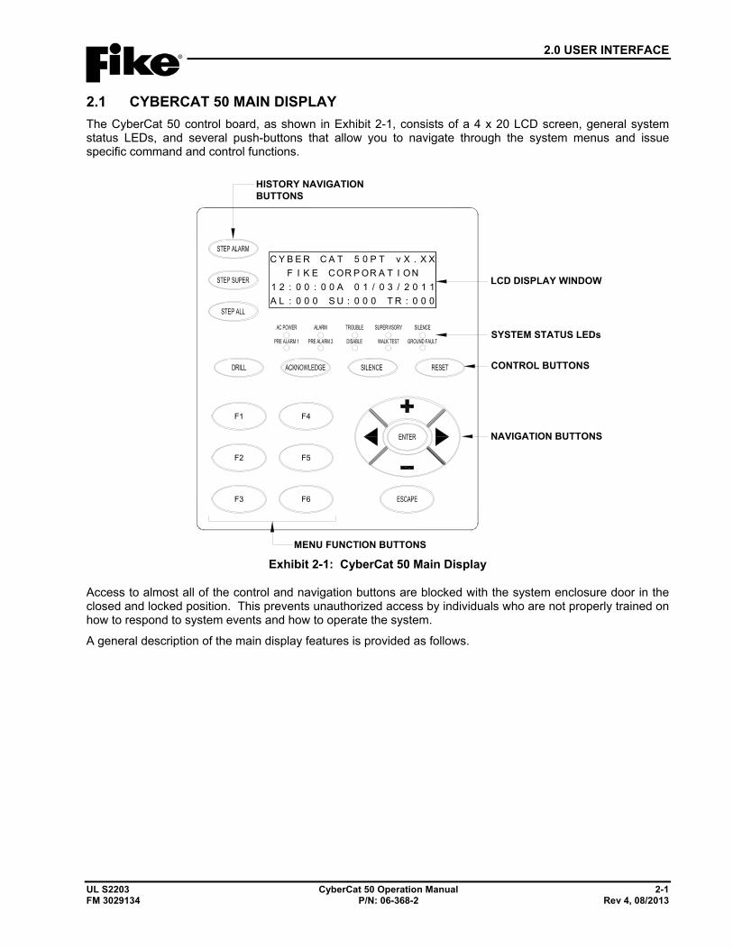
2.0 USER INTERFACE
UL S2203 CyberCat 50 Operation Manual 2-1 FM 3029134 P/N: 06-368-2 Rev 4, 08/2013
2.1 CYBERCAT 50 MAIN DISPLAY The CyberCat 50 control board, as shown in Exhibit 2-1, consists of a 4 x 20 LCD screen, general system status LEDs, and several push-buttons that allow you to navigate through the system menus and issue specific command and control functions.
F1
F2
F3 F6
F5
F4
TACREBYC 5 0 P T v X . X XROCEKIF P OR A T I O N
A00:00:21 0 1 / 0 3 / 2 0 1 1:US000:LA 0 0 0 T R : 0 0 0
SYSTEM STATUS LEDs
LCD DISPLAY WINDOW
CONTROL BUTTONS
NAVIGATION BUTTONS
HISTORY NAVIGATIONBUTTONS
MENU FUNCTION BUTTONS
Exhibit 2-1: CyberCat 50 Main Display
Access to almost all of the control and navigation buttons are blocked with the system enclosure door in the closed and locked position. This prevents unauthorized access by individuals who are not properly trained on how to respond to system events and how to operate the system.
A general description of the main display features is provided as follows.
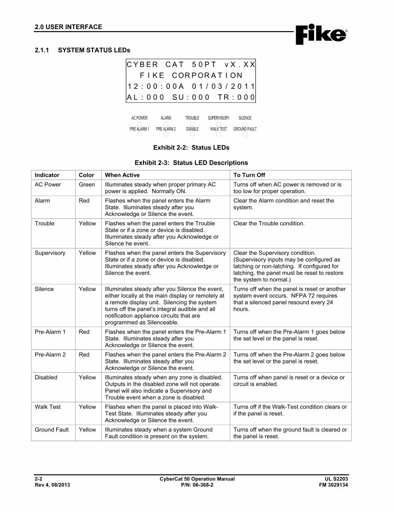
2.0 USER INTERFACE
2-2 CyberCat 50 Operation Manual UL S2203 Rev 4, 08/2013 P/N: 06-368-2 FM 3029134
2.1.1 SYSTEM STATUS LEDs
TACREBYC 5 0 P T v X . X XROCEKIF P OR A T I ON
A00:00:21 0 1 / 0 3 / 2 0 1 1:US000:LA 0 0 0 T R : 0 0 0
Exhibit 2-2: Status LEDs
Exhibit 2-3: Status LED Descriptions
Indicator Color When Active To Turn Off AC Power Green Illuminates steady when proper primary AC
power is applied. Normally ON. Turns off when AC power is removed or is too low for proper operation.
Alarm Red Flashes when the panel enters the Alarm State. Illuminates steady after you Acknowledge or Silence the event.
Clear the Alarm condition and reset the system.
Trouble Yellow Flashes when the panel enters the Trouble State or if a zone or device is disabled. Illuminates steady after you Acknowledge or Silence he event.
Clear the Trouble condition.
Supervisory Yellow Flashes when the panel enters the Supervisory State or if a zone or device is disabled. Illuminates steady after you Acknowledge or Silence the event.
Clear the Supervisory condition. (Supervisory inputs may be configured as latching or non-latching. If configured for latching, the panel must be reset to restore the system to normal.)
Silence Yellow Illuminates steady after you Silence the event, either locally at the main display or remotely at a remote display unit. Silencing the system turns off the panel’s integral audible and all notification appliance circuits that are programmed as Silenceable.
Turns off when the panel is reset or another system event occurs. NFPA 72 requires that a silenced panel resound every 24 hours.
Pre-Alarm 1 Red Flashes when the panel enters the Pre-Alarm 1 State. Illuminates steady after you Acknowledge or Silence the event.
Turns off when the Pre-Alarm 1 goes below the set level or the panel is reset.
Pre-Alarm 2 Red Flashes when the panel enters the Pre-Alarm 2 State. Illuminates steady after you Acknowledge or Silence the event.
Turns off when the Pre-Alarm 2 goes below the set level or the panel is reset.
Disabled Yellow Illuminates steady when any zone is disabled. Outputs in the disabled zone will not operate. Panel will also indicate a Supervisory and Trouble event when a zone is disabled.
Turns off when panel is reset or a device or circuit is enabled.
Walk Test Yellow Flashes when the panel is placed into Walk-Test State. Illuminates steady after you Acknowledge or Silence the event.
Turns off if the Walk-Test condition clears or if the panel is reset.
Ground Fault Yellow Illuminates steady when a system Ground Fault condition is present on the system.
Turns off when the ground fault is cleared or the panel is reset.
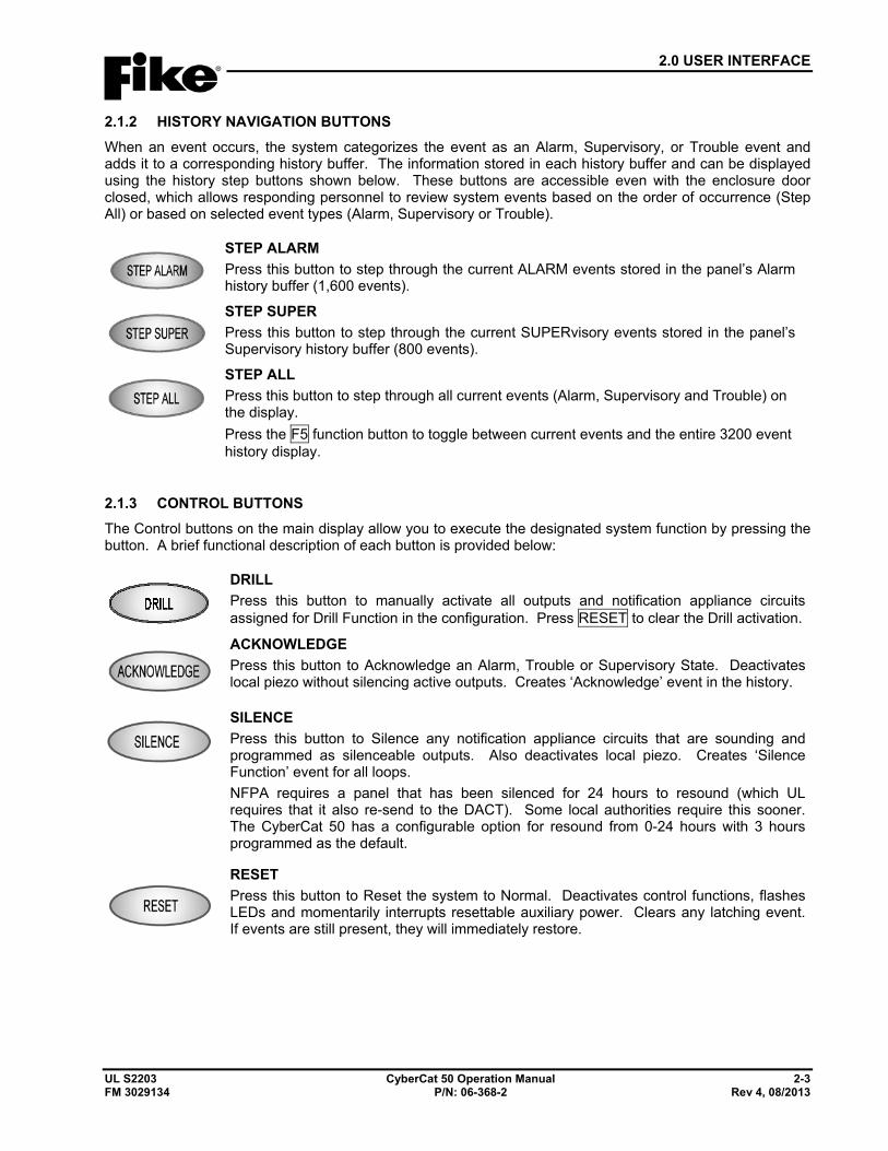
2.0 USER INTERFACE
UL S2203 CyberCat 50 Operation Manual 2-3 FM 3029134 P/N: 06-368-2 Rev 4, 08/2013
2.1.2 HISTORY NAVIGATION BUTTONS When an event occurs, the system categorizes the event as an Alarm, Supervisory, or Trouble event and adds it to a corresponding history buffer. The information stored in each history buffer and can be displayed using the history step buttons shown below. These buttons are accessible even with the enclosure door closed, which allows responding personnel to review system events based on the order of occurrence (Step All) or based on selected event types (Alarm, Supervisory or Trouble).
STEP ALARM Press this button to step through the current ALARM events stored in the panel’s Alarm history buffer (1,600 events).
STEP SUPER Press this button to step through the current SUPERvisory events stored in the panel’s Supervisory history buffer (800 events).
STEP ALL Press this button to step through all current events (Alarm, Supervisory and Trouble) on the display. Press the F5 function button to toggle between current events and the entire 3200 event history display.
2.1.3 CONTROL BUTTONS The Control buttons on the main display allow you to execute the designated system function by pressing the button. A brief functional description of each button is provided below:
DRILL Press this button to manually activate all outputs and notification appliance circuits assigned for Drill Function in the configuration. Press RESET to clear the Drill activation.
ACKNOWLEDGE Press this button to Acknowledge an Alarm, Trouble or Supervisory State. Deactivates local piezo without silencing active outputs. Creates ‘Acknowledge’ event in the history.
SILENCE Press this button to Silence any notification appliance circuits that are sounding and programmed as silenceable outputs. Also deactivates local piezo. Creates ‘Silence Function’ event for all loops. NFPA requires a panel that has been silenced for 24 hours to resound (which UL requires that it also re-send to the DACT). Some local authorities require this sooner. The CyberCat 50 has a configurable option for resound from 0-24 hours with 3 hours programmed as the default.
RESET Press this button to Reset the system to Normal. Deactivates control functions, flashes LEDs and momentarily interrupts resettable auxiliary power. Clears any latching event. If events are still present, they will immediately restore.
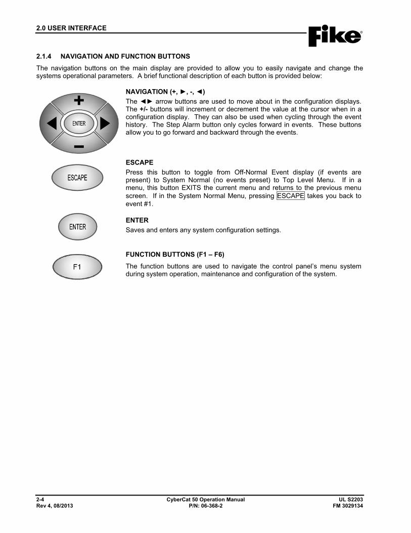
2.0 USER INTERFACE
2-4 CyberCat 50 Operation Manual UL S2203 Rev 4, 08/2013 P/N: 06-368-2 FM 3029134
2.1.4 NAVIGATION AND FUNCTION BUTTONS The navigation buttons on the main display are provided to allow you to easily navigate and change the systems operational parameters. A brief functional description of each button is provided below:
NAVIGATION (+, ►, -, ◄) The ◄► arrow buttons are used to move about in the configuration displays. The +/- buttons will increment or decrement the value at the cursor when in a configuration display. They can also be used when cycling through the event history. The Step Alarm button only cycles forward in events. These buttons allow you to go forward and backward through the events.
ESCAPE Press this button to toggle from Off-Normal Event display (if events are present) to System Normal (no events preset) to Top Level Menu. If in a menu, this button EXITS the current menu and returns to the previous menu screen. If in the System Normal Menu, pressing ESCAPE takes you back to event #1.
ENTER Saves and enters any system configuration settings.
FUNCTION BUTTONS (F1 – F6) The function buttons are used to navigate the control panel’s menu system during system operation, maintenance and configuration of the system.
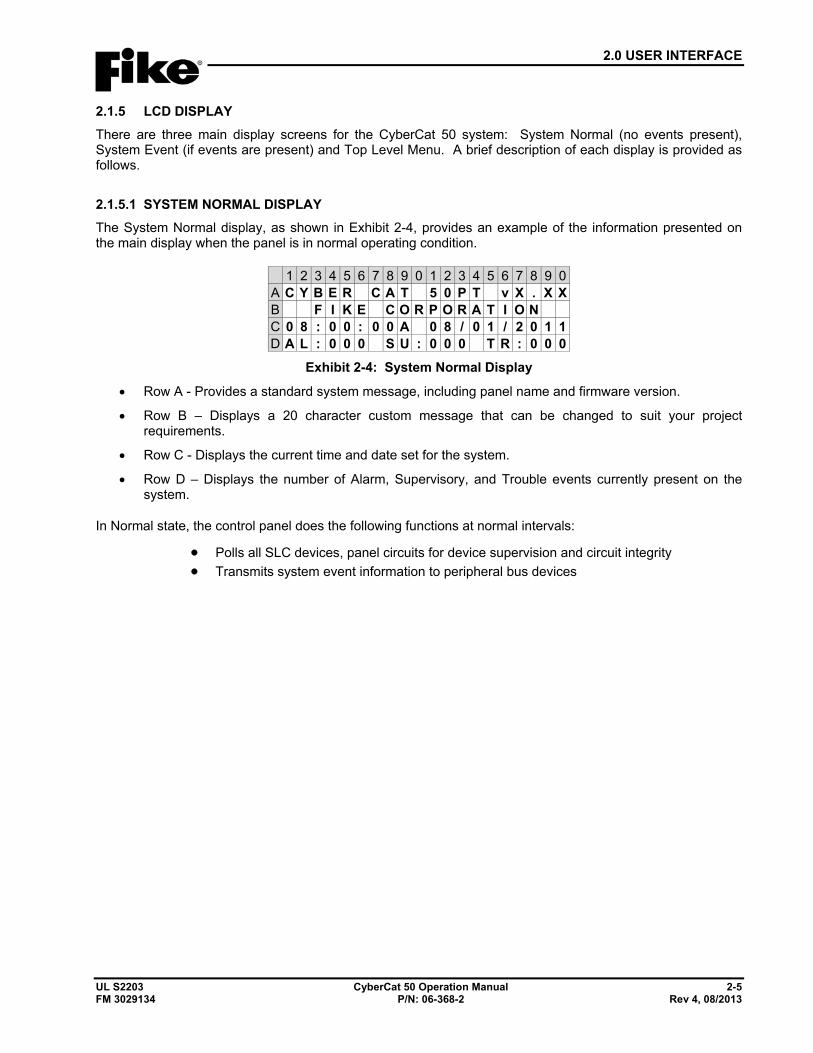
2.0 USER INTERFACE
UL S2203 CyberCat 50 Operation Manual 2-5 FM 3029134 P/N: 06-368-2 Rev 4, 08/2013
2.1.5 LCD DISPLAY There are three main display screens for the CyberCat 50 system: System Normal (no events present), System Event (if events are present) and Top Level Menu. A brief description of each display is provided as follows.
2.1.5.1 SYSTEM NORMAL DISPLAY The System Normal display, as shown in Exhibit 2-4, provides an example of the information presented on the main display when the panel is in normal operating condition.
1 2 3 4 5 6 7 8 9 0 1 2 3 4 5 6 7 8 9 0A C Y B E R C A T 5 0 P T v X . X XB F I K E C O R P O R A T I O NC 0 8 : 0 0 : 0 0 A 0 8 / 0 1 / 2 0 1 1D A L : 0 0 0 S U : 0 0 0 T R : 0 0 0
Exhibit 2-4: System Normal Display
• Row A - Provides a standard system message, including panel name and firmware version.
• Row B – Displays a 20 character custom message that can be changed to suit your project requirements.
• Row C - Displays the current time and date set for the system.
• Row D – Displays the number of Alarm, Supervisory, and Trouble events currently present on the system.
In Normal state, the control panel does the following functions at normal intervals:
• Polls all SLC devices, panel circuits for device supervision and circuit integrity • Transmits system event information to peripheral bus devices
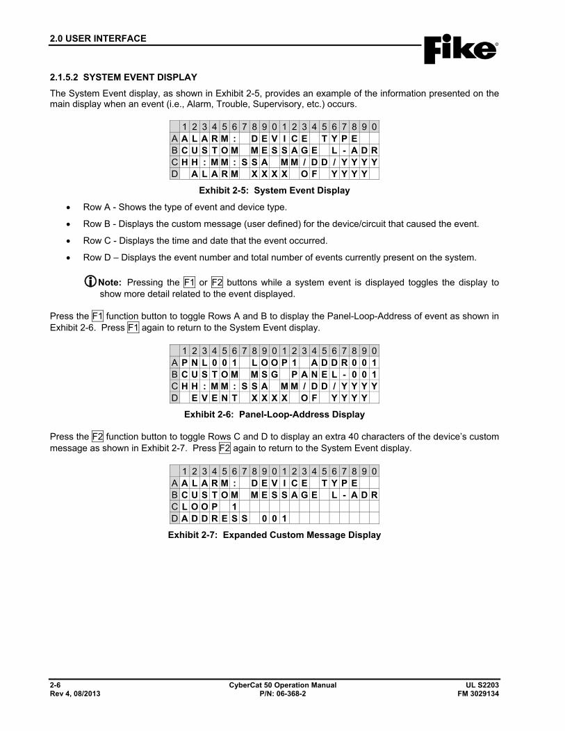
2.0 USER INTERFACE
2-6 CyberCat 50 Operation Manual UL S2203 Rev 4, 08/2013 P/N: 06-368-2 FM 3029134
2.1.5.2 SYSTEM EVENT DISPLAY The System Event display, as shown in Exhibit 2-5, provides an example of the information presented on the main display when an event (i.e., Alarm, Trouble, Supervisory, etc.) occurs.
1 2 3 4 5 6 7 8 9 0 1 2 3 4 5 6 7 8 9 0A A L A R M : D E V I C E T Y P EB C U S T O M M E S S A G E L - A D RC H H : M M : S S A M M / D D / Y Y Y YD A L A R M X X X X O F Y Y Y Y
Exhibit 2-5: System Event Display
• Row A - Shows the type of event and device type.
• Row B - Displays the custom message (user defined) for the device/circuit that caused the event.
• Row C - Displays the time and date that the event occurred.
• Row D – Displays the event number and total number of events currently present on the system.
Note: Pressing the F1 or F2 buttons while a system event is displayed toggles the display to show more detail related to the event displayed.
Press the F1 function button to toggle Rows A and B to display the Panel-Loop-Address of event as shown in Exhibit 2-6. Press F1 again to return to the System Event display.
1 2 3 4 5 6 7 8 9 0 1 2 3 4 5 6 7 8 9 0A P N L 0 0 1 L O O P 1 A D D R 0 0 1B C U S T O M M S G P A N E L - 0 0 1C H H : M M : S S A M M / D D / Y Y Y YD E V E N T X X X X O F Y Y Y Y
Exhibit 2-6: Panel-Loop-Address Display
Press the F2 function button to toggle Rows C and D to display an extra 40 characters of the device’s custom message as shown in Exhibit 2-7. Press F2 again to return to the System Event display.
1 2 3 4 5 6 7 8 9 0 1 2 3 4 5 6 7 8 9 0A A L A R M : D E V I C E T Y P EB C U S T O M M E S S A G E L - A D RC L O O P 1D A D D R E S S 0 0 1
Exhibit 2-7: Expanded Custom Message Display
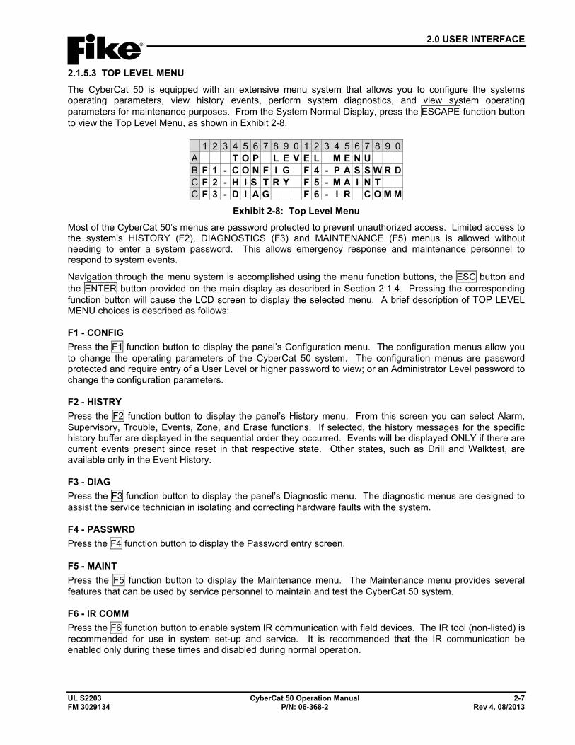
2.0 USER INTERFACE
UL S2203 CyberCat 50 Operation Manual 2-7 FM 3029134 P/N: 06-368-2 Rev 4, 08/2013
2.1.5.3 TOP LEVEL MENU The CyberCat 50 is equipped with an extensive menu system that allows you to configure the systems operating parameters, view history events, perform system diagnostics, and view system operating parameters for maintenance purposes. From the System Normal Display, press the ESCAPE function button to view the Top Level Menu, as shown in Exhibit 2-8.
1 2 3 4 5 6 7 8 9 0 1 2 3 4 5 6 7 8 9 0A T O P L E V E L M E N UB F 1 - C O N F I G F 4 - P A S S W R DC F 2 - H I S T R Y F 5 - M A I N TC F 3 - D I A G F 6 - I R C O M M
Exhibit 2-8: Top Level Menu Most of the CyberCat 50’s menus are password protected to prevent unauthorized access. Limited access to the system’s HISTORY (F2), DIAGNOSTICS (F3) and MAINTENANCE (F5) menus is allowed without needing to enter a system password. This allows emergency response and maintenance personnel to respond to system events.
Navigation through the menu system is accomplished using the menu function buttons, the ESC button and the ENTER button provided on the main display as described in Section 2.1.4. Pressing the corresponding function button will cause the LCD screen to display the selected menu. A brief description of TOP LEVEL MENU choices is described as follows:
F1 - CONFIG Press the F1 function button to display the panel’s Configuration menu. The configuration menus allow you to change the operating parameters of the CyberCat 50 system. The configuration menus are password protected and require entry of a User Level or higher password to view; or an Administrator Level password to change the configuration parameters.
F2 - HISTRY Press the F2 function button to display the panel’s History menu. From this screen you can select Alarm, Supervisory, Trouble, Events, Zone, and Erase functions. If selected, the history messages for the specific history buffer are displayed in the sequential order they occurred. Events will be displayed ONLY if there are current events present since reset in that respective state. Other states, such as Drill and Walktest, are available only in the Event History.
F3 - DIAG Press the F3 function button to display the panel’s Diagnostic menu. The diagnostic menus are designed to assist the service technician in isolating and correcting hardware faults with the system.
F4 - PASSWRD Press the F4 function button to display the Password entry screen.
F5 - MAINT Press the F5 function button to display the Maintenance menu. The Maintenance menu provides several features that can be used by service personnel to maintain and test the CyberCat 50 system.
F6 - IR COMM Press the F6 function button to enable system IR communication with field devices. The IR tool (non-listed) is recommended for use in system set-up and service. It is recommended that the IR communication be enabled only during these times and disabled during normal operation.
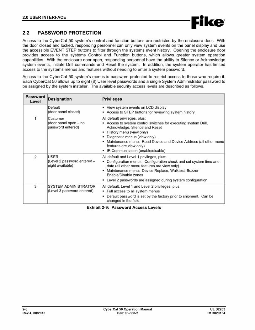
2.0 USER INTERFACE
2-8 CyberCat 50 Operation Manual UL S2203 Rev 4, 08/2013 P/N: 06-368-2 FM 3029134
2.2 PASSWORD PROTECTION Access to the CyberCat 50 system’s control and function buttons are restricted by the enclosure door. With the door closed and locked, responding personnel can only view system events on the panel display and use the accessible EVENT STEP buttons to filter through the systems event history. Opening the enclosure door provides access to the systems Control and Function buttons, which allows greater system operation capabilities. With the enclosure door open, responding personnel have the ability to Silence or Acknowledge system events, initiate Drill commands and Reset the system. In addition, the system operator has limited access to the systems menus and features without needing to enter a system password.
Access to the CyberCat 50 system’s menus is password protected to restrict access to those who require it. Each CyberCat 50 allows up to eight (8) User level passwords and a single System Administrator password to be assigned by the system installer. The available security access levels are described as follows.
Password Level Designation Privileges
Default (door panel closed)
View system events on LCD display Access to STEP buttons for reviewing system history
1 Customer (door panel open – no password entered)
All default privileges, plus: Access to system control switches for executing system Drill,
Acknowledge, Silence and Reset History menu (view only) Diagnostic menus (view only) Maintenance menu: Read Device and Device Address (all other menu
features are view only) IR Communication (enable/disable)
2 USER (Level 2 password entered – eight available)
All default and Level 1 privileges, plus: Configuration menus: Configuration check and set system time and
date (all other menu features are view only). Maintenance menu: Device Replace, Walktest, Buzzer
Enable/Disable zones Level 2 passwords are assigned during system configuration
3 SYSTEM ADMINISTRATOR (Level 3 password entered)
All default, Level 1 and Level 2 privileges, plus: Full access to all system menus Default password is set by the factory prior to shipment. Can be
changed in the field.
Exhibit 2-9: Password Access Levels
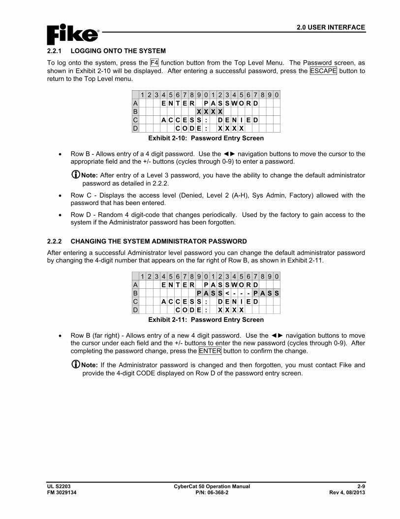
2.0 USER INTERFACE
UL S2203 CyberCat 50 Operation Manual 2-9 FM 3029134 P/N: 06-368-2 Rev 4, 08/2013
2.2.1 LOGGING ONTO THE SYSTEM
To log onto the system, press the F4 function button from the Top Level Menu. The Password screen, as shown in Exhibit 2-10 will be displayed. After entering a successful password, press the ESCAPE button to return to the Top Level menu.
1 2 3 4 5 6 7 8 9 0 1 2 3 4 5 6 7 8 9 0A E N T E R P A S S W O R DB X X X XC A C C E S S : D E N I E DD C O D E : X X X X
Exhibit 2-10: Password Entry Screen
• Row B - Allows entry of a 4 digit password. Use the ◄► navigation buttons to move the cursor to the appropriate field and the +/- buttons (cycles through 0-9) to enter a password.
Note: After entry of a Level 3 password, you have the ability to change the default administrator password as detailed in 2.2.2.
• Row C - Displays the access level (Denied, Level 2 (A-H), Sys Admin, Factory) allowed with the password that has been entered.
• Row D - Random 4 digit-code that changes periodically. Used by the factory to gain access to the system if the Administrator password has been forgotten.
2.2.2 CHANGING THE SYSTEM ADMINISTRATOR PASSWORD After entering a successful Administrator level password you can change the default administrator password by changing the 4-digit number that appears on the far right of Row B, as shown in Exhibit 2-11.
1 2 3 4 5 6 7 8 9 0 1 2 3 4 5 6 7 8 9 0A E N T E R P A S S W O R DB P A S S < - - - P A S SC A C C E S S : D E N I E DD C O D E : X X X X
Exhibit 2-11: Password Entry Screen
• Row B (far right) - Allows entry of a new 4 digit password. Use the ◄► navigation buttons to move the cursor under each field and the +/- buttons to enter the new password (cycles through 0-9). After completing the password change, press the ENTER button to confirm the change.
Note: If the Administrator password is changed and then forgotten, you must contact Fike and provide the 4-digit CODE displayed on Row D of the password entry screen.
2.0 USER INTERFACE
2-10 CyberCat 50 Operation Manual UL S2203 Rev 4, 08/2013 P/N: 06-368-2 FM 3029134
Reserved for future use.
3.0 SYSTEM OPERATION
UL S2203 CyberCat 50 Operation Manual 3-1 FM 3029134 P/N: 06-368-2 Rev 4, 08/2013
3.1 GENERAL OPERATION The CyberCat 50 system operation is based upon a Zone and State Relationship. Each device, input or output must be assigned to at least one Zone and State. A Zone is defined as a specific area of protection or hazard to protect. There are 253 software zones available on the CyberCat 50. A state is defined as a mode or condition of operation for the fire alarm system. Input devices can be assigned to individual zones or a range of zones (only one zone is typical). Panel events, such as AC Power, Battery, NAC Supervision, or any other main panel troubles, report to Zone 254. Zone 254 is also an ANY ZONE selection that CAN be disabled. Zone 255 is an ANY ZONE selection that CAN NOT be disabled. Output devices may be configured for any zone (Z255) or maximum zones in action table (3 x 32 = 96 different zones).
When an input is activated, it will cause its associated zone(s) to enter an Operational State. Any detection device will cause their associated zone(s) to enter the Alarm State (or Supervisory if programmed). All other input devices must be configured for a specific type of Input State, which will cause its associated zone(s) to enter that Operational State. Output devices are then configured to activate when their associated zone(s) enter into the configured state(s).
Operation Example: When an input device configured for Supervisory Input for Zone 3 is activated, it will cause any output configured for Supervisory Zone 3 to turn ON.
3.1.1 AC TROUBLE DELAY Central and Remote Supervising Station Systems require the use of a Digital Alarm Communicator Transmitter (DACT), 10-2528 or 10-2254 Reverse Polarity Module. These modules transmit all information from the panel output, to the Supervising Station. Since Loss of AC is non-critical and secondary power is available, Supervising Stations typically need not see immediate AC power low troubles. AC power loss trouble will not immediately be sent to the dialer for AC power low or loss Trouble, if it is the only fault. The communication will wait the programmed amount of time. The CyberCat 50 controller is programmable for a 0-30 hour (in 1 hour increments) AC trouble delay. The piezo and the display of the event do not follow the delay of the relay and are immediately annunciated if the AC trouble is the only trouble.
3.1.2 DAYLIGHT SAVINGS The control panel will automatically change the time forward/backward at the appropriate times if daylight savings is selected, YES. The control panel will not change the time if the daylight savings is selected NO. Daylight Saving Time (for the U.S. and its territories) is NOT observed in Hawaii, American Samoa, Guam, Puerto Rico, the Virgin Islands, the Eastern Time Zone portion of the State of Indiana, and by most of Arizona (with the exception of the Navajo Indian Reservation in Arizona).
Control panels with firmware Version 3.00 and higher operate as follows: Daylight Saving Time will start on the second Sunday in March, and change back to standard time on the first Sunday in November.
Control panels with firmware older than 3.00 operate as follows: Daylight Saving Time begins for most of the United States at 2 a.m. on the first Sunday of April. Time reverts to standard time at 2 a.m. on the last Sunday of October.
3.1.3 SILENCE INHIBIT Certain jurisdictions require a silence inhibit timer. This feature requires that the panel not allow silencing for one minute following the first alarm event. If this is configured to be ENABLED, the SILENCE button on the Display (or other Silence input) will not silence the panel for one minute following the receipt of the first alarm event.
3.0 SYSTEM OPERATION
3-2 CyberCat 50 Operation Manual UL S2203 Rev 4, 08/2013 P/N: 06-368-2 FM 3029134
3.1.4 SILENCE REMINDER Certain jurisdictions require a silence reminder. This feature requires that the panel produce a momentary pulse from the panel piezo/buzzer following the silencing of outputs. If this is configured to be ENABLED, the momentary piezo pulse is ½ second long every 14 seconds on a silenced panel.
3.1.5 STATE COUNTERS The CyberCat 50 can count states to create an activation of an output. The state counters are created from Eclipse addressable devices ONLY (e.g., If zone 1 has several alarms, the output can be programmed to activate upon receipt of 2 alarms total). VESDA does not participate in State Counters.
3.1.6 NETWORK OPERATION The CyberCat 50 cannot be connected to Fike’s standard panel network (RS485 or Fiber Optic) that allows two-way communication between panels. However, when equipped with Fike’s Ethernet Module (P/N 10-2627), the panel can be remotely monitored by another panel equipped with an Ethernet module over the facilities Local Area Network (LAN). Communication between the Ethernet module and the host control panel is one-way only; therefore, it cannot be used for true panel networking which requires two-way communication between panels.
Even though the CyberCat 50 cannot participate in the standard panel network, its menu system still contains configuration and diagnostic functions that pertain to panel networking as these options are required to properly configure the Ethernet Module for panel monitoring. Refer to Fike document 06-388, “Ethernet Module” for more information.
3.1.7 POSITIVE ALARM SEQUENCE This feature is enabled or disabled for all outputs connected to the panel. When enabled, an Alarm signal from an automatic fire detection device shall be Acknowledged at the main panel display, remote keypad or input module within 15 seconds after annunciation of the Alarm event in order to initiate the alarm investigation phase. Annunciation to this point consists of only the CyberCat 50 local piezo sounder and the event message on the main panel display and/or remote display. If the alarm signal is not acknowledged within 15 seconds, all notification circuits assigned to the same zone as the initiating device will be activated immediately.
During the Alarm investigation phase, trained personnel have up to 180 seconds to evaluate the fire condition and reset the panel. If the panel is not reset during this investigation phase, all notification circuits assigned to the same zone as the initiating device will be activated upon expiration of the 180 second investigation phase. If a second automatic fire detector is actuated during the alarm investigation phase, or any other initiating device (such as manual alarm station) is actuated, all notification circuits assigned to the same zone as the initiating device will be activated immediately.
A means has been provided to bypass this feature without re-configuring the panel. An input module configured with the PAS INHIBIT function will disable this feature temporarily while the module is activated and produce a trouble event. The module must be returned to its normal status to re-enable the positive alarm sequence feature. This will clear the trouble event from the module actuation and restore the system to normal operation.
3.0 SYSTEM OPERATION
UL S2203 CyberCat 50 Operation Manual 3-3 FM 3029134 P/N: 06-368-2 Rev 4, 08/2013
3.1.8 EMERGENCY COMMUNICATION OPERATION When used for Emergency Communication System (ECS) service, the CyberCat 50 panel serves as the central control point for the system and will coordinate the activation and operation of both the In-Building Fire Emergency Voice/Alarm Communication System (EVACS) and the In-Building Mass Notification System (MNS), when both are utilized. Activation of the audio adjunct panel for EVAC or MNS operation can be initiated automatically by the CyberCat 50 panel or manually using the controls provided on the audio adjunct panel itself or by using SLC input devices (monitor modules) configured for ECS operation, that are connected to a UL 2017 listed contact initiating device.
The audio adjunct panels (AAP1 and AAP3) receive their command interface from the RS485 peripheral bus connection to the CyberCat 50 control panel. This connection allows the audio adjunct amplifiers to activate automatically based on the CyberCat 50’s zone and state relationships. Each amplifier card is programmed to play one of its sixteen preset audio messages (stored on the amp) through its four speaker circuits based on an active panel zone and state (i.e., Alarm, Test Alarm, Supervisory and Process). For example: When an alarm is detected, the associated zone and state information is transmitted over the RS485 bus to each amplifier card. If the amplifier card has been programmed to activate in response to the system event, the assigned audio message is decompressed and played through the speaker circuits. Amplifiers not programmed to respond to the event will remain off unless programmed to play either the default ALERT message or an alternate custom message. Each amplifier is capable of storing up to sixteen (16) individual, custom audio messages (maximum 30 seconds in length) and tones in a digital format on the board’s internal memory for playback.
Each audio adjunct panel is equipped with a paging control card that has thirteen (13) programmable switches. These switches can be used by emergency responders to manually initiate any of the following fire alarm or mass notification commands to building occupants:
• Voice Alert – Places selected zone(s) into the Alert State. Assigned Alert message will be played in selected zone(s).
• Voice EVAC – Places selected zone(s) into the Evacuation state. Assigned EVAC message will be played in selected zone(s).
• Voice or MNS Page – Initiates a page to selected zone(s). Use AAP microphone to deliver audio massage to selected zone(s).
• Voice or MNS Record Page – Initiates a record and repeat page to the selected zone(s). Use the AAP microphone to deliver the audio message to selected zone(s). Live page will be recorded and repeated over-and-over until canceled or over written.
• Voice or MNS Play Message ID – Plays the selected message ID(s) to selected zone(s). • Voice Page to Alert – Initiates a page to all active Alert zone(s). • Voice Page to EVAC – Initiates a page to all active EVAC zone(s). • MNS Reset – Resets the MNS system. Voice events are not affected. • MNS Silence – Silences all active MNS events. Voice events are not affected.
Note: Manual activation via switch press will override automatic operation.
Note: The integral paging microphone must be used in conjunction with the programmable switches to initiate selective or all-call pages over the amplifier speaker circuits.
Application Note: MNS operation requires that a status LED be provided to indicate when the MNS system is active and when a ‘Trouble’ event has occurred on the system. The Audio Adjunct Panel provides an MNS/ECS LED; however, indication of MNS ‘Trouble’ events require that a 20-zone remote annunciator (P/N 10-2667), with an LED configured to provide continuous indication of an MNS system trouble event, be installed directly adjacent to the panel.
Refer to Fike document 06-576, “Amplifier Kit” and 06-613, “LOC Digital Paging Assembly” manuals for further details.
3.0 SYSTEM OPERATION
3-4 CyberCat 50 Operation Manual UL S2203 Rev 4, 08/2013 P/N: 06-368-2 FM 3029134
3.1.8.1 VOICE SYSTEM PRIORITIES Activation of Fike’s emergency communication system can be initiated automatically by the CyberCat 50 panel for Alarm, Test Alarm, Supervisory and Process states or manually via activation of an input switch configured for Voice or MNS operation (as stated above). In order to resolve which panel event or input switch should have operational control priority over another, Fike’s voice system allows you to assign a control priority level to the panel events and switches that initiate voice operations. Each event or switch can be assigned a priority level from 0 to 254 using the panel’s configuration software (C-Linx), with 1 being the highest priority and 254 being the lowest priority. A setting of 0 disables the control priorities and must be used on all systems where priority schemes are not utilized.
Activation of a panel event or switch with a lower priority setting cannot override a panel event or switch with a higher priority. A panel event or switch can override another panel event or switch with the same priority setting or a lower priority setting.
Note: Assigning a priority to panel events does not affect the normal operation of the panel where an Alarm event always has priority over a Supervisory event. It simply assigns a priority to the audio messages that will be played by the voice system amplifiers in response to a switch press or panel event.
3.1.9 DEVICE LED OPERATION Each CyberCat 50 addressable device is equipped with an LED that flashes to provide positive indication of the device status. The following responses are expected from the device LED:
Device Status LED Operation Device Status LED Operation Normal Flashes green Trouble (open) Flashes yellow (slow) Pre-Alarm 1 Flashes red (slow) Trouble (short) Flashes yellow (fast) Pre-Alarm 2 Flashes red (fast) Trouble (general) Steady yellow Alarm (Sum) Steady red Test Alarm Flashes red/green
3.2 PANEL MENU STRUCTURE The CyberCat 50 control panel is equipped with an extensive menu structure. Refer to Appendix D for a complete breakdown of the system menu structure. Access to certain panel menus and functions (Configuration Menus) are password protected and require the operator to log onto the system in order to view them or gain access to make changes. Refer to Section 2.2.1 for details on how to log onto the system.
Access to system menus such as History, Diagnostics and Maintenance are not password protected. This allows responding personnel to easily review system events as they occur by accessing the History Menu and diagnose potential problems occurring on the system via the Diagnostics Menus. The Maintenance Menu provides several functions that are designed to assist service personnel in maintaining the system. A detailed description of these panel menus and available functions is provided in Sections 4.0, 5.0 and 6.0 of this manual for reference purposes.
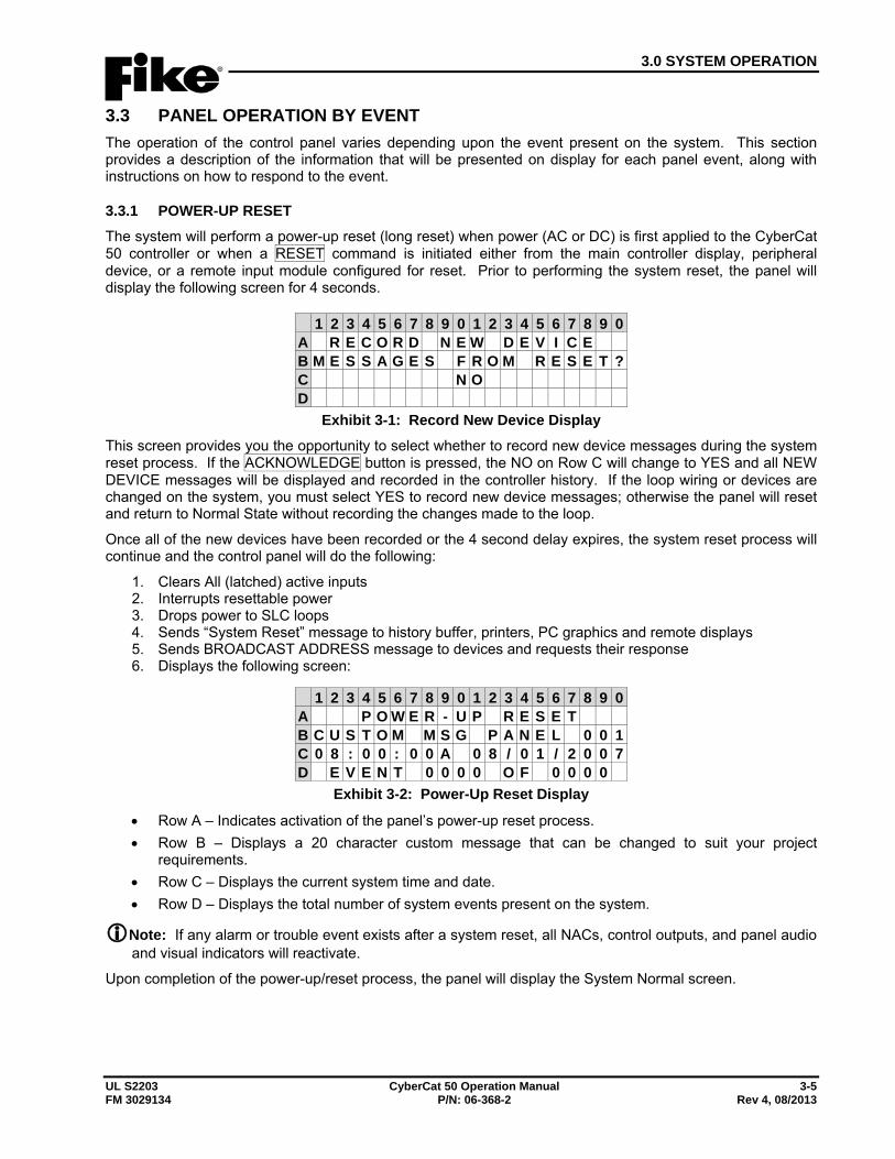
3.0 SYSTEM OPERATION
UL S2203 CyberCat 50 Operation Manual 3-5 FM 3029134 P/N: 06-368-2 Rev 4, 08/2013
3.3 PANEL OPERATION BY EVENT The operation of the control panel varies depending upon the event present on the system. This section provides a description of the information that will be presented on display for each panel event, along with instructions on how to respond to the event.
3.3.1 POWER-UP RESET The system will perform a power-up reset (long reset) when power (AC or DC) is first applied to the CyberCat 50 controller or when a RESET command is initiated either from the main controller display, peripheral device, or a remote input module configured for reset. Prior to performing the system reset, the panel will display the following screen for 4 seconds.
1 2 3 4 5 6 7 8 9 0 1 2 3 4 5 6 7 8 9 0A R E C O R D N E W D E V I C EB M E S S A G E S F R O M R E S E T ?C N OD
Exhibit 3-1: Record New Device Display This screen provides you the opportunity to select whether to record new device messages during the system reset process. If the ACKNOWLEDGE button is pressed, the NO on Row C will change to YES and all NEW DEVICE messages will be displayed and recorded in the controller history. If the loop wiring or devices are changed on the system, you must select YES to record new device messages; otherwise the panel will reset and return to Normal State without recording the changes made to the loop.
Once all of the new devices have been recorded or the 4 second delay expires, the system reset process will continue and the control panel will do the following:
1. Clears All (latched) active inputs 2. Interrupts resettable power 3. Drops power to SLC loops 4. Sends “System Reset” message to history buffer, printers, PC graphics and remote displays 5. Sends BROADCAST ADDRESS message to devices and requests their response 6. Displays the following screen:
1 2 3 4 5 6 7 8 9 0 1 2 3 4 5 6 7 8 9 0A P O W E R - U P R E S E TB C U S T O M M S G P A N E L 0 0 1C 0 8 : 0 0 : 0 0 A 0 8 / 0 1 / 2 0 0 7D E V E N T 0 0 0 0 O F 0 0 0 0
Exhibit 3-2: Power-Up Reset Display
• Row A – Indicates activation of the panel’s power-up reset process. • Row B – Displays a 20 character custom message that can be changed to suit your project
requirements. • Row C – Displays the current system time and date. • Row D – Displays the total number of system events present on the system.
Note: If any alarm or trouble event exists after a system reset, all NACs, control outputs, and panel audio and visual indicators will reactivate.
Upon completion of the power-up/reset process, the panel will display the System Normal screen.
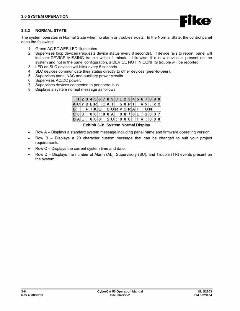
3.0 SYSTEM OPERATION
3-6 CyberCat 50 Operation Manual UL S2203 Rev 4, 08/2013 P/N: 06-368-2 FM 3029134
3.3.2 NORMAL STATE The system operates in Normal State when no alarm or troubles exists. In the Normal State, the control panel does the following:
1. Green AC POWER LED illuminates. 2. Supervises loop devices (requests device status every 8 seconds). If device fails to report, panel will
indicate DEVICE MISSING trouble within 1 minute. Likewise, if a new device is present on the system and not in the panel configuration, a DEVICE NOT IN CONFIG trouble will be reported.
3. LED on SLC devices will blink every 5 seconds. 4. SLC devices communicate their status directly to other devices (peer-to-peer). 5. Supervises panel NAC and auxiliary power circuits. 6. Supervises AC/DC power. 7. Supervises devices connected to peripheral bus. 8. Displays a system normal message as follows:
1 2 3 4 5 6 7 8 9 0 1 2 3 4 5 6 7 8 9 0A C Y B E R C A T 5 0 P T v x . x xB F I K E C O R P O R A T I O NC 0 8 : 0 0 : 0 0 A 0 8 / 0 1 / 2 0 0 7D A L : 0 0 0 S U : 0 0 0 T R : 0 0 0
Exhibit 3-3: System Normal Display
• Row A – Displays a standard system message including panel name and firmware operating version. • Row B – Displays a 20 character custom message that can be changed to suit your project
requirements. • Row C – Displays the current system time and date. • Row D – Displays the number of Alarm (AL), Supervisory (SU), and Trouble (TR) events present on
the system.
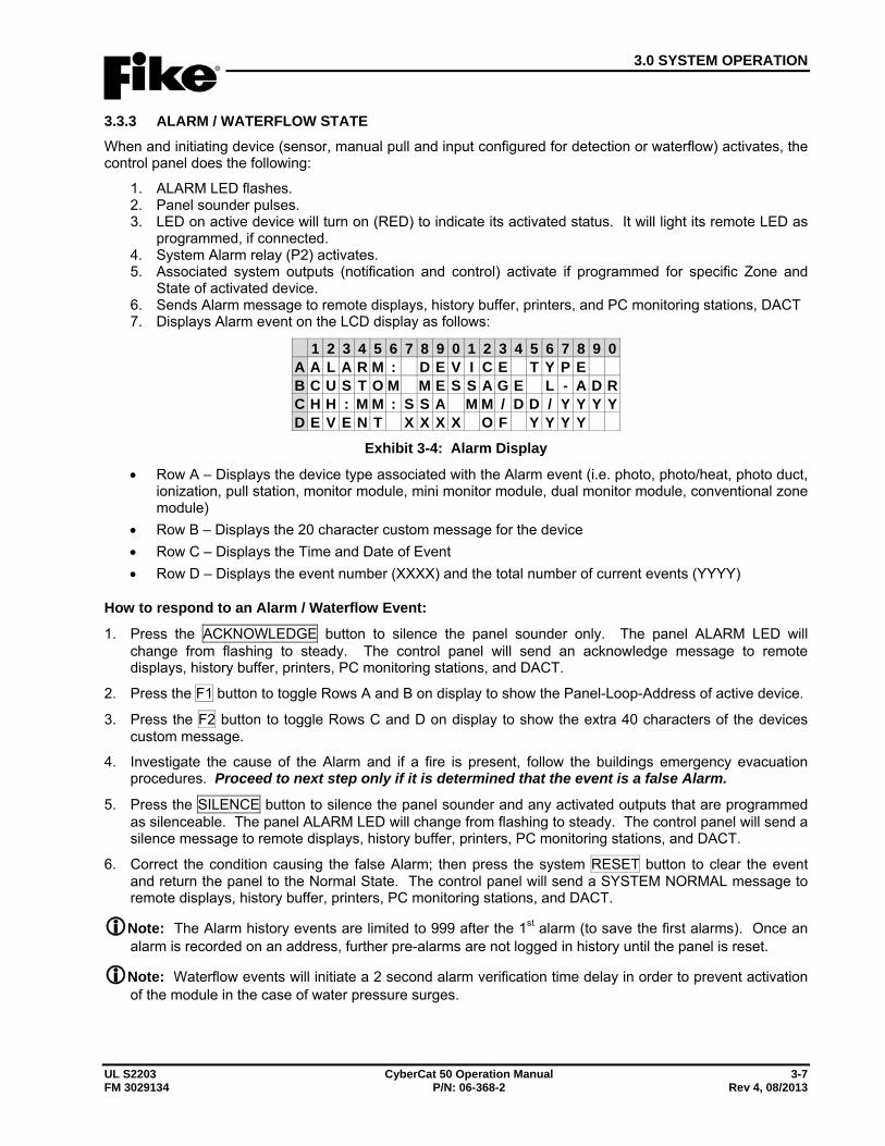
3.0 SYSTEM OPERATION
UL S2203 CyberCat 50 Operation Manual 3-7 FM 3029134 P/N: 06-368-2 Rev 4, 08/2013
3.3.3 ALARM / WATERFLOW STATE When and initiating device (sensor, manual pull and input configured for detection or waterflow) activates, the control panel does the following:
1. ALARM LED flashes. 2. Panel sounder pulses. 3. LED on active device will turn on (RED) to indicate its activated status. It will light its remote LED as
programmed, if connected. 4. System Alarm relay (P2) activates. 5. Associated system outputs (notification and control) activate if programmed for specific Zone and
State of activated device. 6. Sends Alarm message to remote displays, history buffer, printers, and PC monitoring stations, DACT 7. Displays Alarm event on the LCD display as follows:
1 2 3 4 5 6 7 8 9 0 1 2 3 4 5 6 7 8 9 0A A L A R M : D E V I C E T Y P EB C U S T O M M E S S A G E L - A D RC H H : M M : S S A M M / D D / Y Y Y YD E V E N T X X X X O F Y Y Y Y
Exhibit 3-4: Alarm Display
• Row A – Displays the device type associated with the Alarm event (i.e. photo, photo/heat, photo duct, ionization, pull station, monitor module, mini monitor module, dual monitor module, conventional zone module)
• Row B – Displays the 20 character custom message for the device • Row C – Displays the Time and Date of Event • Row D – Displays the event number (XXXX) and the total number of current events (YYYY)
How to respond to an Alarm / Waterflow Event:
1. Press the ACKNOWLEDGE button to silence the panel sounder only. The panel ALARM LED will change from flashing to steady. The control panel will send an acknowledge message to remote displays, history buffer, printers, PC monitoring stations, and DACT.
2. Press the F1 button to toggle Rows A and B on display to show the Panel-Loop-Address of active device.
3. Press the F2 button to toggle Rows C and D on display to show the extra 40 characters of the devices custom message.
4. Investigate the cause of the Alarm and if a fire is present, follow the buildings emergency evacuation procedures. Proceed to next step only if it is determined that the event is a false Alarm.
5. Press the SILENCE button to silence the panel sounder and any activated outputs that are programmed as silenceable. The panel ALARM LED will change from flashing to steady. The control panel will send a silence message to remote displays, history buffer, printers, PC monitoring stations, and DACT.
6. Correct the condition causing the false Alarm; then press the system RESET button to clear the event and return the panel to the Normal State. The control panel will send a SYSTEM NORMAL message to remote displays, history buffer, printers, PC monitoring stations, and DACT.
Note: The Alarm history events are limited to 999 after the 1st alarm (to save the first alarms). Once an alarm is recorded on an address, further pre-alarms are not logged in history until the panel is reset.
Note: Waterflow events will initiate a 2 second alarm verification time delay in order to prevent activation of the module in the case of water pressure surges.
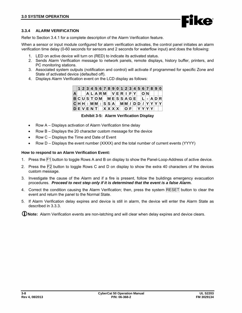
3.0 SYSTEM OPERATION
3-8 CyberCat 50 Operation Manual UL S2203 Rev 4, 08/2013 P/N: 06-368-2 FM 3029134
3.3.4 ALARM VERIFICATION Refer to Section 3.4.1 for a complete description of the Alarm Verification feature.
When a sensor or input module configured for alarm verification activates, the control panel initiates an alarm verification time delay (0-60 seconds for sensors and 2 seconds for waterflow input) and does the following:
1. LED on active device will turn on (RED) to indicate its activated status. 2. Sends Alarm Verification message to network panels, remote displays, history buffer, printers, and
PC monitoring stations. 3. Associated system outputs (notification and control) will activate if programmed for specific Zone and
State of activated device (defaulted off). 4. Displays Alarm Verification event on the LCD display as follows:
1 2 3 4 5 6 7 8 9 0 1 2 3 4 5 6 7 8 9 0A A L A R M V E R I F Y O NB C U S T O M M E S S A G E L - A D RC H H : M M : S S A M M / D D / Y Y Y YD E V E N T X X X X O F Y Y Y Y
Exhibit 3-5: Alarm Verification Display
• Row A – Displays activation of Alarm Verification time delay • Row B – Displays the 20 character custom message for the device • Row C – Displays the Time and Date of Event • Row D – Displays the event number (XXXX) and the total number of current events (YYYY)
How to respond to an Alarm Verification Event:
1. Press the F1 button to toggle Rows A and B on display to show the Panel-Loop-Address of active device.
2. Press the F2 button to toggle Rows C and D on display to show the extra 40 characters of the devices custom message.
3. Investigate the cause of the Alarm and if a fire is present, follow the buildings emergency evacuation procedures. Proceed to next step only if it is determined that the event is a false Alarm.
4. Correct the condition causing the Alarm Verification; then, press the system RESET button to clear the event and return the panel to the Normal State.
5. If Alarm Verification delay expires and device is still in alarm, the device will enter the Alarm State as described in 3.3.3.
Note: Alarm Verification events are non-latching and will clear when delay expires and device clears.
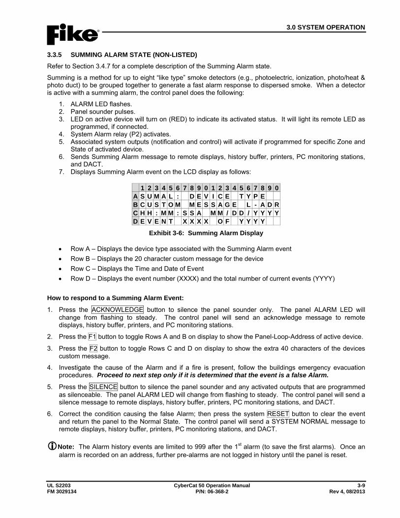
3.0 SYSTEM OPERATION
UL S2203 CyberCat 50 Operation Manual 3-9 FM 3029134 P/N: 06-368-2 Rev 4, 08/2013
3.3.5 SUMMING ALARM STATE (NON-LISTED) Refer to Section 3.4.7 for a complete description of the Summing Alarm state.
Summing is a method for up to eight “like type” smoke detectors (e.g., photoelectric, ionization, photo/heat & photo duct) to be grouped together to generate a fast alarm response to dispersed smoke. When a detector is active with a summing alarm, the control panel does the following:
1. ALARM LED flashes. 2. Panel sounder pulses. 3. LED on active device will turn on (RED) to indicate its activated status. It will light its remote LED as
programmed, if connected. 4. System Alarm relay (P2) activates. 5. Associated system outputs (notification and control) will activate if programmed for specific Zone and
State of activated device. 6. Sends Summing Alarm message to remote displays, history buffer, printers, PC monitoring stations,
and DACT. 7. Displays Summing Alarm event on the LCD display as follows:
1 2 3 4 5 6 7 8 9 0 1 2 3 4 5 6 7 8 9 0A S U M A L : D E V I C E T Y P EB C U S T O M M E S S A G E L - A D RC H H : M M : S S A M M / D D / Y Y Y YD E V E N T X X X X O F Y Y Y Y
Exhibit 3-6: Summing Alarm Display
• Row A – Displays the device type associated with the Summing Alarm event • Row B – Displays the 20 character custom message for the device • Row C – Displays the Time and Date of Event • Row D – Displays the event number (XXXX) and the total number of current events (YYYY)
How to respond to a Summing Alarm Event:
1. Press the ACKNOWLEDGE button to silence the panel sounder only. The panel ALARM LED will change from flashing to steady. The control panel will send an acknowledge message to remote displays, history buffer, printers, and PC monitoring stations.
2. Press the F1 button to toggle Rows A and B on display to show the Panel-Loop-Address of active device.
3. Press the F2 button to toggle Rows C and D on display to show the extra 40 characters of the devices custom message.
4. Investigate the cause of the Alarm and if a fire is present, follow the buildings emergency evacuation procedures. Proceed to next step only if it is determined that the event is a false Alarm.
5. Press the SILENCE button to silence the panel sounder and any activated outputs that are programmed as silenceable. The panel ALARM LED will change from flashing to steady. The control panel will send a silence message to remote displays, history buffer, printers, PC monitoring stations, and DACT.
6. Correct the condition causing the false Alarm; then press the system RESET button to clear the event and return the panel to the Normal State. The control panel will send a SYSTEM NORMAL message to remote displays, history buffer, printers, PC monitoring stations, and DACT.
Note: The Alarm history events are limited to 999 after the 1st alarm (to save the first alarms). Once an alarm is recorded on an address, further pre-alarms are not logged in history until the panel is reset.
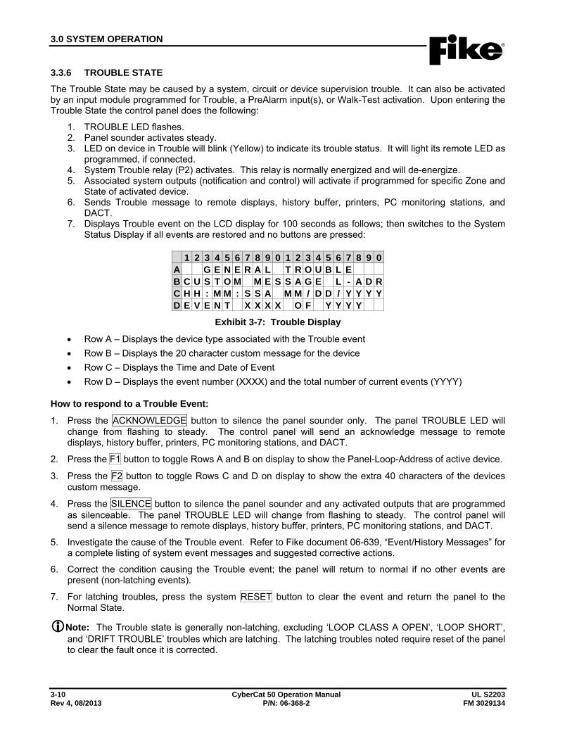
3.0 SYSTEM OPERATION
3-10 CyberCat 50 Operation Manual UL S2203 Rev 4, 08/2013 P/N: 06-368-2 FM 3029134
3.3.6 TROUBLE STATE The Trouble State may be caused by a system, circuit or device supervision trouble. It can also be activated by an input module programmed for Trouble, a PreAlarm input(s), or Walk-Test activation. Upon entering the Trouble State the control panel does the following:
1. TROUBLE LED flashes. 2. Panel sounder activates steady. 3. LED on device in Trouble will blink (Yellow) to indicate its trouble status. It will light its remote LED as
programmed, if connected. 4. System Trouble relay (P2) activates. This relay is normally energized and will de-energize. 5. Associated system outputs (notification and control) will activate if programmed for specific Zone and
State of activated device. 6. Sends Trouble message to remote displays, history buffer, printers, PC monitoring stations, and
DACT. 7. Displays Trouble event on the LCD display for 100 seconds as follows; then switches to the System
Status Display if all events are restored and no buttons are pressed:
1 2 3 4 5 6 7 8 9 0 1 2 3 4 5 6 7 8 9 0A G E N E R A L T R O U B L EB C U S T O M M E S S A G E L - A D RC H H : M M : S S A M M / D D / Y Y Y YD E V E N T X X X X O F Y Y Y Y
Exhibit 3-7: Trouble Display
• Row A – Displays the device type associated with the Trouble event • Row B – Displays the 20 character custom message for the device • Row C – Displays the Time and Date of Event • Row D – Displays the event number (XXXX) and the total number of current events (YYYY)
How to respond to a Trouble Event:
1. Press the ACKNOWLEDGE button to silence the panel sounder only. The panel TROUBLE LED will change from flashing to steady. The control panel will send an acknowledge message to remote displays, history buffer, printers, PC monitoring stations, and DACT.
2. Press the F1 button to toggle Rows A and B on display to show the Panel-Loop-Address of active device.
3. Press the F2 button to toggle Rows C and D on display to show the extra 40 characters of the devices custom message.
4. Press the SILENCE button to silence the panel sounder and any activated outputs that are programmed as silenceable. The panel TROUBLE LED will change from flashing to steady. The control panel will send a silence message to remote displays, history buffer, printers, PC monitoring stations, and DACT.
5. Investigate the cause of the Trouble event. Refer to Fike document 06-639, “Event/History Messages” for a complete listing of system event messages and suggested corrective actions.
6. Correct the condition causing the Trouble event; the panel will return to normal if no other events are present (non-latching events).
7. For latching troubles, press the system RESET button to clear the event and return the panel to the Normal State.
Note: The Trouble state is generally non-latching, excluding ‘LOOP CLASS A OPEN’, ‘LOOP SHORT’, and ‘DRIFT TROUBLE’ troubles which are latching. The latching troubles noted require reset of the panel to clear the fault once it is corrected.
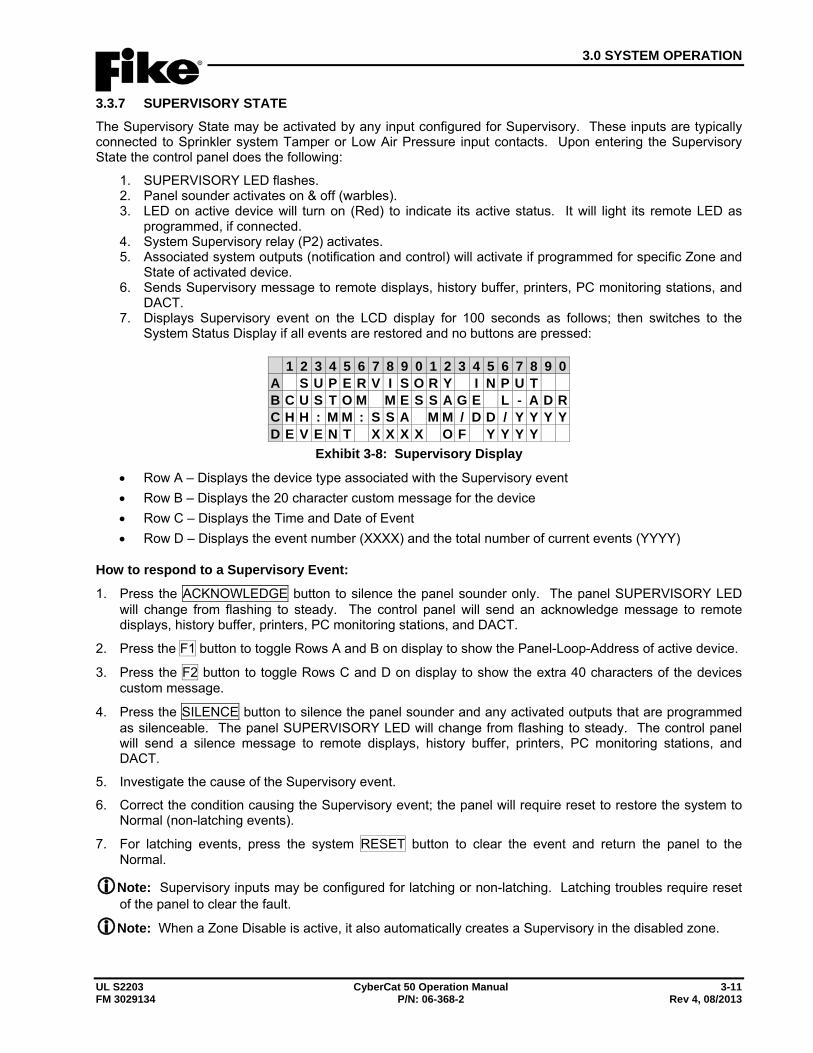
3.0 SYSTEM OPERATION
UL S2203 CyberCat 50 Operation Manual 3-11 FM 3029134 P/N: 06-368-2 Rev 4, 08/2013
3.3.7 SUPERVISORY STATE The Supervisory State may be activated by any input configured for Supervisory. These inputs are typically connected to Sprinkler system Tamper or Low Air Pressure input contacts. Upon entering the Supervisory State the control panel does the following:
1. SUPERVISORY LED flashes. 2. Panel sounder activates on & off (warbles). 3. LED on active device will turn on (Red) to indicate its active status. It will light its remote LED as
programmed, if connected. 4. System Supervisory relay (P2) activates. 5. Associated system outputs (notification and control) will activate if programmed for specific Zone and
State of activated device. 6. Sends Supervisory message to remote displays, history buffer, printers, PC monitoring stations, and
DACT. 7. Displays Supervisory event on the LCD display for 100 seconds as follows; then switches to the
System Status Display if all events are restored and no buttons are pressed:
1 2 3 4 5 6 7 8 9 0 1 2 3 4 5 6 7 8 9 0A S U P E R V I S O R Y I N P U TB C U S T O M M E S S A G E L - A D RC H H : M M : S S A M M / D D / Y Y Y YD E V E N T X X X X O F Y Y Y Y
Exhibit 3-8: Supervisory Display
• Row A – Displays the device type associated with the Supervisory event • Row B – Displays the 20 character custom message for the device • Row C – Displays the Time and Date of Event • Row D – Displays the event number (XXXX) and the total number of current events (YYYY)
How to respond to a Supervisory Event:
1. Press the ACKNOWLEDGE button to silence the panel sounder only. The panel SUPERVISORY LED will change from flashing to steady. The control panel will send an acknowledge message to remote displays, history buffer, printers, PC monitoring stations, and DACT.
2. Press the F1 button to toggle Rows A and B on display to show the Panel-Loop-Address of active device.
3. Press the F2 button to toggle Rows C and D on display to show the extra 40 characters of the devices custom message.
4. Press the SILENCE button to silence the panel sounder and any activated outputs that are programmed as silenceable. The panel SUPERVISORY LED will change from flashing to steady. The control panel will send a silence message to remote displays, history buffer, printers, PC monitoring stations, and DACT.
5. Investigate the cause of the Supervisory event.
6. Correct the condition causing the Supervisory event; the panel will require reset to restore the system to Normal (non-latching events).
7. For latching events, press the system RESET button to clear the event and return the panel to the Normal.
Note: Supervisory inputs may be configured for latching or non-latching. Latching troubles require reset of the panel to clear the fault.
Note: When a Zone Disable is active, it also automatically creates a Supervisory in the disabled zone.
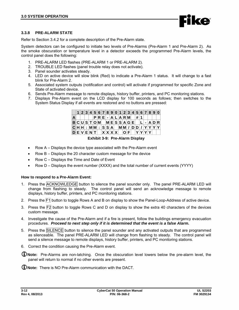
3.0 SYSTEM OPERATION
3-12 CyberCat 50 Operation Manual UL S2203 Rev 4, 08/2013 P/N: 06-368-2 FM 3029134
3.3.8 PRE-ALARM STATE Refer to Section 3.4.2 for a complete description of the Pre-Alarm state.
System detectors can be configured to initiate two levels of Pre-Alarms (Pre-Alarm 1 and Pre-Alarm 2). As the smoke obscuration or temperature level in a detector exceeds the programmed Pre-Alarm levels, the control panel does the following:
1. PRE-ALARM LED flashes (PRE-ALARM 1 or PRE-ALARM 2). 2. TROUBLE LED flashes (panel trouble relay does not activate). 3. Panel sounder activates steady. 4. LED on active device will slow blink (Red) to indicate a Pre-Alarm 1 status. It will change to a fast
blink for Pre-Alarm 2. 5. Associated system outputs (notification and control) will activate if programmed for specific Zone and
State of activated device. 6. Sends Pre-Alarm message to remote displays, history buffer, printers, and PC monitoring stations. 7. Displays Pre-Alarm event on the LCD display for 100 seconds as follows; then switches to the
System Status Display if all events are restored and no buttons are pressed:
1 2 3 4 5 6 7 8 9 0 1 2 3 4 5 6 7 8 9 0A P R E - A L A R M # 1B C U S T O M M E S S A G E L - A D RC H H : M M : S S A M M / D D / Y Y Y YD E V E N T X X X X O F Y Y Y Y
Exhibit 3-9: Pre-Alarm Display
• Row A – Displays the device type associated with the Pre-Alarm event • Row B – Displays the 20 character custom message for the device • Row C – Displays the Time and Date of Event • Row D – Displays the event number (XXXX) and the total number of current events (YYYY)
How to respond to a Pre-Alarm Event:
1. Press the ACKNOWLEDGE button to silence the panel sounder only. The panel PRE-ALARM LED will change from flashing to steady. The control panel will send an acknowledge message to remote displays, history buffer, printers, and PC monitoring stations.
2. Press the F1 button to toggle Rows A and B on display to show the Panel-Loop-Address of active device.
3. Press the F2 button to toggle Rows C and D on display to show the extra 40 characters of the devices custom message.
4. Investigate the cause of the Pre-Alarm and if a fire is present, follow the buildings emergency evacuation procedures. Proceed to next step only if it is determined that the event is a false Alarm.
5. Press the SILENCE button to silence the panel sounder and any activated outputs that are programmed as silenceable. The panel PRE-ALARM LED will change from flashing to steady. The control panel will send a silence message to remote displays, history buffer, printers, and PC monitoring stations.
6. Correct the condition causing the Pre-Alarm event.
Note: Pre-Alarms are non-latching. Once the obscuration level lowers below the pre-alarm level, the panel will return to normal if no other events are present.
Note: There is NO Pre-Alarm communication with the DACT.

3.0 SYSTEM OPERATION
UL S2203 CyberCat 50 Operation Manual 3-13 FM 3029134 P/N: 06-368-2 Rev 4, 08/2013
3.3.9 PROCESS STATE The Process State may be activated by any input configured for Process. These inputs are typically connected to non-alarm system contacts used for process management functions. When a Process event occurs the control panel does the following:
1. LED on active device will turn on (Red) to indicate its active status. 2. Associated system outputs (notification and control) will activate if programmed for specific Zone and
State of activated device. 3. Sends Process message to remote displays, history buffer, printers, and PC monitoring stations. 4. Displays Process event on the LCD display for 100 seconds as follows; then switches to the System
Status Display if all events are restored and no buttons are pressed:
1 2 3 4 5 6 7 8 9 0 1 2 3 4 5 6 7 8 9 0A P R O C E S S I N P U TB C U S T O M M E S S A G E L - A D RC H H : M M : S S A M M / D D / Y Y Y YD E V E N T X X X X O F Y Y Y Y
Exhibit 3-10: Process Display
• Row A – Displays the device type associated with the Process event • Row B – Displays the 20 character custom message for the device • Row C – Displays the Time and Date of Event • Row D – Displays the event number (XXXX) and the total number of current events (YYYY)
How to respond to a Process Event:
1. Press the F1 button to toggle Rows A and B on display to show the Panel-Loop-Address of active device.
2. Press the F2 button to toggle Rows C and D on display to show the extra 40 characters of the devices custom message.
3. Check the Process message for the type of event and location.
4. Correct the condition causing the Process event.
Note: Process events are non-latching. Once the Process contact is restored, the panel will return to normal if no other events are present.
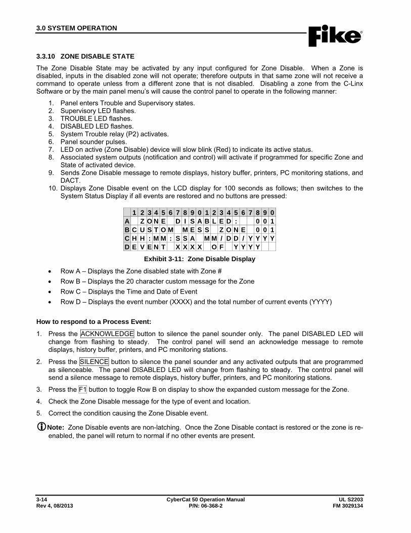
3.0 SYSTEM OPERATION
3-14 CyberCat 50 Operation Manual UL S2203 Rev 4, 08/2013 P/N: 06-368-2 FM 3029134
3.3.10 ZONE DISABLE STATE The Zone Disable State may be activated by any input configured for Zone Disable. When a Zone is disabled, inputs in the disabled zone will not operate; therefore outputs in that same zone will not receive a command to operate unless from a different zone that is not disabled. Disabling a zone from the C-Linx Software or by the main panel menu’s will cause the control panel to operate in the following manner:
1. Panel enters Trouble and Supervisory states. 2. Supervisory LED flashes. 3. TROUBLE LED flashes. 4. DISABLED LED flashes. 5. System Trouble relay (P2) activates. 6. Panel sounder pulses. 7. LED on active (Zone Disable) device will slow blink (Red) to indicate its active status. 8. Associated system outputs (notification and control) will activate if programmed for specific Zone and
State of activated device. 9. Sends Zone Disable message to remote displays, history buffer, printers, PC monitoring stations, and
DACT. 10. Displays Zone Disable event on the LCD display for 100 seconds as follows; then switches to the
System Status Display if all events are restored and no buttons are pressed:
1 2 3 4 5 6 7 8 9 0 1 2 3 4 5 6 7 8 9 0A Z O N E D I S A B L E D : 0 0 1B C U S T O M M E S S Z O N E 0 0 1C H H : M M : S S A M M / D D / Y Y Y YD E V E N T X X X X O F Y Y Y Y
Exhibit 3-11: Zone Disable Display
• Row A – Displays the Zone disabled state with Zone # • Row B – Displays the 20 character custom message for the Zone • Row C – Displays the Time and Date of Event • Row D – Displays the event number (XXXX) and the total number of current events (YYYY)
How to respond to a Process Event:
1. Press the ACKNOWLEDGE button to silence the panel sounder only. The panel DISABLED LED will change from flashing to steady. The control panel will send an acknowledge message to remote displays, history buffer, printers, and PC monitoring stations.
2. Press the SILENCE button to silence the panel sounder and any activated outputs that are programmed as silenceable. The panel DISABLED LED will change from flashing to steady. The control panel will send a silence message to remote displays, history buffer, printers, and PC monitoring stations.
3. Press the F1 button to toggle Row B on display to show the expanded custom message for the Zone.
4. Check the Zone Disable message for the type of event and location.
5. Correct the condition causing the Zone Disable event.
Note: Zone Disable events are non-latching. Once the Zone Disable contact is restored or the zone is re-enabled, the panel will return to normal if no other events are present.
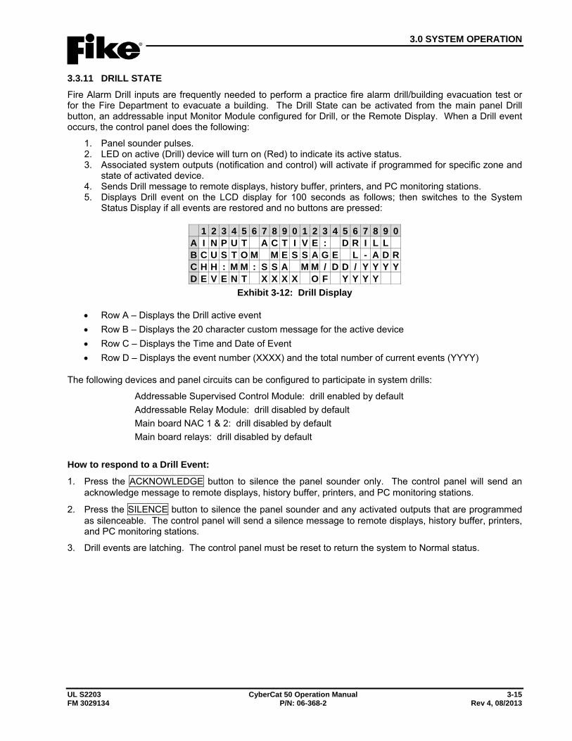
3.0 SYSTEM OPERATION
UL S2203 CyberCat 50 Operation Manual 3-15 FM 3029134 P/N: 06-368-2 Rev 4, 08/2013
3.3.11 DRILL STATE Fire Alarm Drill inputs are frequently needed to perform a practice fire alarm drill/building evacuation test or for the Fire Department to evacuate a building. The Drill State can be activated from the main panel Drill button, an addressable input Monitor Module configured for Drill, or the Remote Display. When a Drill event occurs, the control panel does the following:
1. Panel sounder pulses. 2. LED on active (Drill) device will turn on (Red) to indicate its active status. 3. Associated system outputs (notification and control) will activate if programmed for specific zone and
state of activated device. 4. Sends Drill message to remote displays, history buffer, printers, and PC monitoring stations. 5. Displays Drill event on the LCD display for 100 seconds as follows; then switches to the System
Status Display if all events are restored and no buttons are pressed:
1 2 3 4 5 6 7 8 9 0 1 2 3 4 5 6 7 8 9 0A I N P U T A C T I V E : D R I L LB C U S T O M M E S S A G E L - A D RC H H : M M : S S A M M / D D / Y Y Y YD E V E N T X X X X O F Y Y Y Y
Exhibit 3-12: Drill Display
• Row A – Displays the Drill active event • Row B – Displays the 20 character custom message for the active device • Row C – Displays the Time and Date of Event • Row D – Displays the event number (XXXX) and the total number of current events (YYYY)
The following devices and panel circuits can be configured to participate in system drills:
Addressable Supervised Control Module: drill enabled by default Addressable Relay Module: drill disabled by default Main board NAC 1 & 2: drill disabled by default Main board relays: drill disabled by default
How to respond to a Drill Event:
1. Press the ACKNOWLEDGE button to silence the panel sounder only. The control panel will send an acknowledge message to remote displays, history buffer, printers, and PC monitoring stations.
2. Press the SILENCE button to silence the panel sounder and any activated outputs that are programmed as silenceable. The control panel will send a silence message to remote displays, history buffer, printers, and PC monitoring stations.
3. Drill events are latching. The control panel must be reset to return the system to Normal status.
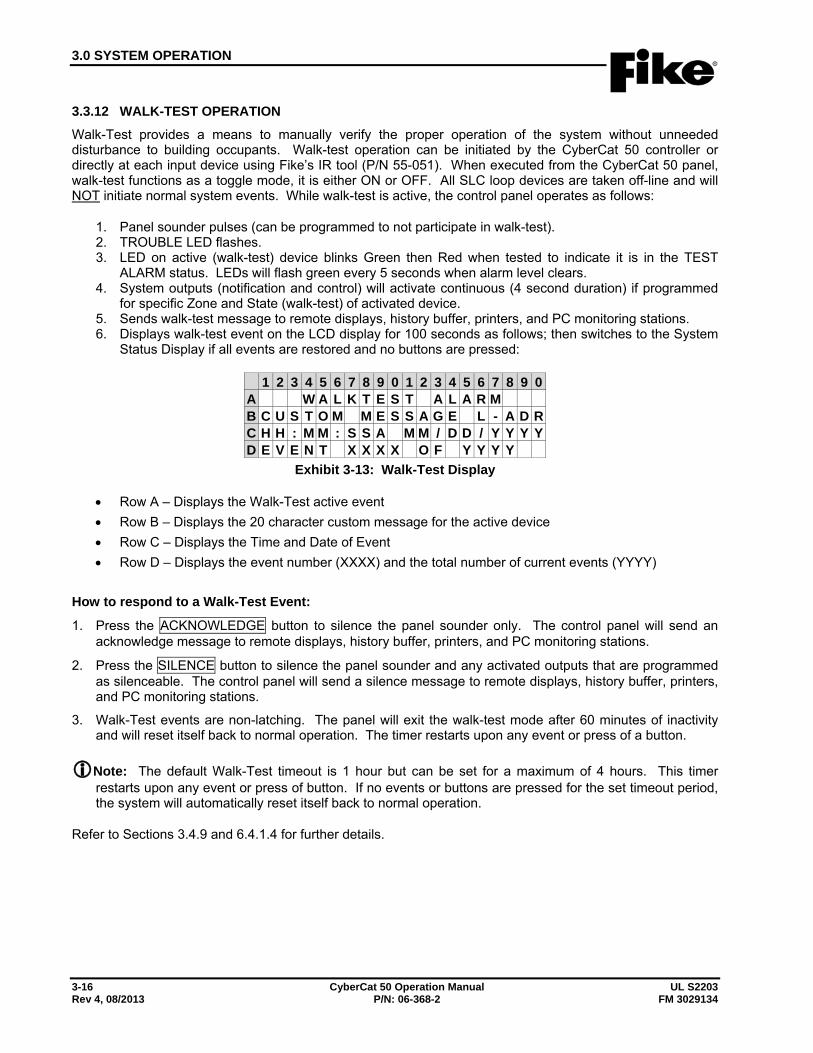
3.0 SYSTEM OPERATION
3-16 CyberCat 50 Operation Manual UL S2203 Rev 4, 08/2013 P/N: 06-368-2 FM 3029134
3.3.12 WALK-TEST OPERATION Walk-Test provides a means to manually verify the proper operation of the system without unneeded disturbance to building occupants. Walk-test operation can be initiated by the CyberCat 50 controller or directly at each input device using Fike’s IR tool (P/N 55-051). When executed from the CyberCat 50 panel, walk-test functions as a toggle mode, it is either ON or OFF. All SLC loop devices are taken off-line and will NOT initiate normal system events. While walk-test is active, the control panel operates as follows:
1. Panel sounder pulses (can be programmed to not participate in walk-test). 2. TROUBLE LED flashes. 3. LED on active (walk-test) device blinks Green then Red when tested to indicate it is in the TEST
ALARM status. LEDs will flash green every 5 seconds when alarm level clears. 4. System outputs (notification and control) will activate continuous (4 second duration) if programmed
for specific Zone and State (walk-test) of activated device. 5. Sends walk-test message to remote displays, history buffer, printers, and PC monitoring stations. 6. Displays walk-test event on the LCD display for 100 seconds as follows; then switches to the System
Status Display if all events are restored and no buttons are pressed:
1 2 3 4 5 6 7 8 9 0 1 2 3 4 5 6 7 8 9 0A W A L K T E S T A L A R MB C U S T O M M E S S A G E L - A D RC H H : M M : S S A M M / D D / Y Y Y YD E V E N T X X X X O F Y Y Y Y
Exhibit 3-13: Walk-Test Display
• Row A – Displays the Walk-Test active event • Row B – Displays the 20 character custom message for the active device • Row C – Displays the Time and Date of Event • Row D – Displays the event number (XXXX) and the total number of current events (YYYY)
How to respond to a Walk-Test Event:
1. Press the ACKNOWLEDGE button to silence the panel sounder only. The control panel will send an acknowledge message to remote displays, history buffer, printers, and PC monitoring stations.
2. Press the SILENCE button to silence the panel sounder and any activated outputs that are programmed as silenceable. The control panel will send a silence message to remote displays, history buffer, printers, and PC monitoring stations.
3. Walk-Test events are non-latching. The panel will exit the walk-test mode after 60 minutes of inactivity and will reset itself back to normal operation. The timer restarts upon any event or press of a button.
Note: The default Walk-Test timeout is 1 hour but can be set for a maximum of 4 hours. This timer restarts upon any event or press of button. If no events or buttons are pressed for the set timeout period, the system will automatically reset itself back to normal operation.
Refer to Sections 3.4.9 and 6.4.1.4 for further details.
3.0 SYSTEM OPERATION
UL S2203 CyberCat 50 Operation Manual 3-17 FM 3029134 P/N: 06-368-2 Rev 4, 08/2013
3.3.13 FAN RESTART OPERATION Fan Restart operation provides a means to sequence the restart of AHU fan motors after they have been shut down in response to a fire alarm event. Fan restart operation can only be accomplished using addressable relay modules connected to the panel’s SLC loop programmed for ‘AHU Shutdown Relay’ operation. By default, each AHU Shutdown relay will be set to activate for an ALARM event in any of its assigned zones and will automatically default to a normally energized relay. Each addressable relay can be configured with a restart delay (0 – 255 seconds).
Upon activation of an ALARM event, each AHU Shutdown relay will activate and remain active even after the control panel is reset. After reset, the fan restart sequence must be initiated manually using any of the following sources: 1) control panel’s “AHU ON” function that can be found in MAINTENANCE MENU 2, 2) addressable input module configured for “Fan Restart”, 3) peripheral device (i.e., remote display or input/output card) switch configured for Fan Restart. Once initiated, the panel will start the automatic fan restart sequence and the AHU Shutdown relays will deactivate according to their programmed time delay allowing the startup of the AHU fan motors to be staggered.
Critical Note: Fan restart shall NOT be used for smoke control operation.
Critical Note: Fan restart relay(s) will remain active through a system reset and will only de-activate after the programmed time delay has expired.
3.3.13.1 AHU FIRE KEY Activation of the addressable relays for Fan Restart can be further restricted by requiring the activation of an input module configured for ‘AHU FIRE KEY’ operation before a Fan Restart switch can be acted on by the panel. This is a system variable that is either enabled or disabled via the panel’s CONFIGURATION MENU 7 > F1-AHUKEY. When enabled, an “AHU FIRE KEY” must be active prior to activation of a Fan Restart switch in order for the control panel to act upon it. Activation of a Fan Restart switch prior to activation of the ‘AHU FIRE KEY’ will not start the fan restart sequence. The panel will only indicate the activation of the Fan Restart switch on its display and the event will be recorded in the panel’s history buffer.
Note: If fire key operation is used, the switch (key or button operation) must be installed with limited access and must be UL 864 listed for Fire Protective Signaling System use.
3.0 SYSTEM OPERATION
3-18 CyberCat 50 Operation Manual UL S2203 Rev 4, 08/2013 P/N: 06-368-2 FM 3029134
3.4 INTELLIGENT SENSOR FEATURES The CyberCat 50’s intelligent sensors offer a wide range of configurable features that can be used to provide optimum system performance. A brief description of each feature is provided in this Section for reference purposes. The following table shows the available features for each sensor:
Sensor Ala
rm
Verif
icat
ion
Pre-
Ala
rm 1
Pre-
Ala
rm 2
Acc
limat
e
Day
/Nig
ht
Sens
itivi
ty
Drif
t C
ompe
nsat
ion
Wal
ktes
t
Dev
ice
Sum
min
g Fl
ame
Enha
nce
Smol
der
Photoelectric X X X X X X X X Photo/Heat X X X X X X X X X Photo Duct X X X X X X X X Ionization X X X X X X X X X Heat (FT/RR) X X X X FAAST X X X X X X
Exhibit 3-14: Sensor Programming Features
3.4.1 ALARM VERIFICATION Alarm verification is used to delay the sensors automatic response to an alarm while the system/device verifies the alarm situation. If a sensor programmed for alarm verification exceeds its alarm threshold, it broadcasts the Alarm Verification state and starts a timer (0-60 seconds). Output devices programmed for Alarm Verification in that same zone will turn ON until silenced (if programmed as Silenceable) in reaction to the Alarm Verification event. If the sensor is still above the alarm threshold at the end of the verification period, the Alarm condition will be broadcast. Alarm Verification state will then be OFF. The control panel LED’s and piezo does not operate during the Alarm Verification state. An Alarm Verification event is recorded in the event history buffer.
3.4.2 PRE-ALARM Pre-Alarms are used for performing an early warning of a fire alarm. There are two levels of Pre-Alarms that may be configured, Pre-Alarm #1 and Pre-Alarm #2 for each sensor. Pre-Alarms may be independently enabled/disabled in the configuration of each sensor. If Pre-Alarms are enabled in a sensor and the Pre-Alarm level is exceeded, the panel will log the Pre-Alarm 1 or 2 state and any output circuit/module programmed for the respective Pre-Alarm State and Zone will turn ON until silenced (if programmed as Silenceable). The respective Pre-Alarm and Trouble LED’s flash on the control panel until acknowledged or silenced, but the trouble outputs/states are not activated. There is also no Pre-Alarm communication with the DACT.
Example: As smoke increases in a hazard, the obscuration of the photo-electric sensor rises. Zero %/ft obscuration is a completely clean environment. As the smoke amount rises, the obscuration percentage rises, up to 4%/ft (UL smoke box test maximum alarm level recognized). Pre-Alarm #1 should be set for the lowest level of obscuration percentage desired for notification. Pre-Alarm #2 should be set slightly higher as the obscuration rises. The alarm level is then set at the 3rd level up in the obscuration percentage. The C-Linx Software forces these separated levels and does not allow them to overlap.
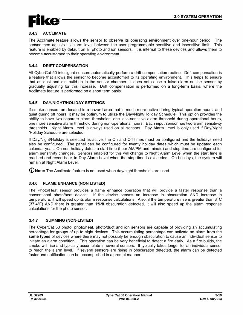
3.0 SYSTEM OPERATION
UL S2203 CyberCat 50 Operation Manual 3-19 FM 3029134 P/N: 06-368-2 Rev 4, 08/2013
3.4.3 ACCLIMATE The Acclimate feature allows the sensor to observe its operating environment over one-hour period. The sensor then adjusts its alarm level between the user programmable sensitive and insensitive limit. This feature is enabled by default on all photo and ion sensors. It is internal to these devices and allows them to become accustomed to their operating environment.
3.4.4 DRIFT COMPENSATION All CyberCat 50 intelligent sensors automatically perform a drift compensation routine. Drift compensation is a feature that allows the sensor to become accustomed to its operating environment. This helps to ensure that as dust and dirt build-up in the sensor chamber, it does not cause a false alarm on the sensor by gradually adjusting for this increase. Drift compensation is performed on a long-term basis, where the Acclimate feature is performed on a short term basis.
3.4.5 DAY/NIGHT/HOLIDAY SETTINGS If smoke sensors are located in a hazard area that is much more active during typical operation hours, and quiet during off hours, it may be optimum to utilize the Day/Night/Holiday Schedule. This option provides the ability to have two separate alarm thresholds; one less sensitive alarm threshold during operational hours, one more sensitive alarm threshold during non-operational hours. Each input sensor has two alarm sensitivity thresholds. Night Alarm Level is always used on all sensors. Day Alarm Level is only used if Day/Night /Holiday Schedule are selected.
If Day/Night/Holiday is selected as active, the On and Off times must be configured and the holidays need also be configured. The panel can be configured for twenty holiday dates which must be updated each calendar year. On non-holiday dates, a start time (hour AM/PM and minute) and stop time are configured for alarm sensitivity changes. Sensors enabled for this will change to Night Alarm Level when the start time is reached and revert back to Day Alarm Level when the stop time is exceeded. On holidays, the system will remain at Night Alarm Level.
Note: The Acclimate feature is not used when day/night thresholds are used.
3.4.6 FLAME ENHANCE (NON LISTED) The Photo/Heat sensor provides a flame enhance operation that will provide a faster response than a conventional photo/heat device. If the device senses an increase in obscuration AND increase in temperature, it will speed up its alarm response calculations. Also, if the temperature rise is greater than 3◦ C (37.4°F) AND there is greater than 1%/ft obscuration detected, it will also speed up the alarm response calculations for the photo sensor.
3.4.7 SUMMING (NON-LISTED) The CyberCat 50 photo, photo/heat, photo/duct and ion sensors are capable of providing an accumulating percentage for groups of up to eight devices. This accumulating percentage can activate an alarm from the same types of devices where there may not possibly be enough obscuration to cause an individual sensor to initiate an alarm condition. This operation can be very beneficial to detect a fire early. As a fire builds, the smoke will rise and typically accumulate in several sensors. It typically takes longer for an individual sensor to reach the alarm level. If several sensors are rising in obscuration detected, the alarm can be detected faster and notification can be accomplished in a prompt manner.
3.0 SYSTEM OPERATION
3-20 CyberCat 50 Operation Manual UL S2203 Rev 4, 08/2013 P/N: 06-368-2 FM 3029134
SUMMING EXAMPLE: Photo Sensor SUMMER, Loop 1 - address 5. This device is configured to sum the following devices which are physically located near one another in the hazard: Loop 1, addresses 10,11,12,13,14,15,16, and 17. It is programmed for a summing threshold of 4%/ft. Each Summee (addresses noted previous) is configured for the obscuration to be transmitted to the summer at 0.5%/ft, 0.6%/ft, 0.7%/ft (up to 8 levels). When the summer obtains a SUM of the obscurations that are >= 4%/ft it reports the event to the system.
Note: As the obscuration level of the summee rises and falls, it will broadcast an “Analog Value” event message in relation to the summing functionality. The summer will look at the most current values sent from the summee to calculate the SUM for the SUMMING ALARM.
To set up this operation, a single sensor is selected as a SUMMER. The summer can look at information from 8 photo (or ion, same type as summer and same loop at summer - can include the summer) sensors called the SUMMEE(s). The summer will total the obscuration percentages received from each summee defined. The summer can be set to alarm from 1-10%/ft (programmable in 0.5%/ft. increments). Each summee has configuration settings for defining the level of obscuration to be transmitted to the summer (0.5 – 4%/ft in 0.1%/ft increments). Summing groups can overlap and there is no limitation on the number of Summers. The summer can be configured to report as any one of the following system event types when activated: Alarm, Summing Alarm, Supervisory Latching, Supervisory Non-Latching, Pre-Alarm1, and Pre-Alarm 2.
3.4.8 SMOLDER (NON LISTED) The Ionization sensor provides a smolder enhancement feature that allows the sensitivity of the sensor to be increased where there is a slow buildup of smoke. If the device senses an increase in obscuration of approximately 30% of alarm, it will speed up its alarm response calculations.
3.4.9 WALK-TEST Walk-testing allows for the system sensors (i.e., photo, photo/heat, photo/duct and ion) to be tested for proper operation without unneeded disturbance to building occupants. By default, all sensors are configured to participate in a system walk-test using smoke. Sensor configuration can be changed using the panel’s programming software C-Linx to allow walk-testing using Fike’s IR tool. The IR tool must be used for duct detector walk-testing. Sensors may only be activated once during the walk-test mode. Refer to Section 6.4.1.4 for further details.
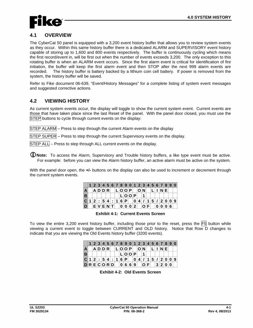
4.0 SYSTEM HISTORY
UL S2203 CyberCat 50 Operation Manual 4-1 FM 3029134 P/N: 06-368-2 Rev 4, 08/2013
4.1 OVERVIEW The CyberCat 50 panel is equipped with a 3,200 event history buffer that allows you to review system events as they occur. Within this same history buffer there is a dedicated ALARM and SUPERVISORY event history capable of storing up to 1,600 and 800 events respectively. The buffer is continuously cycling which means the first record/event in, will be first out when the number of events exceeds 3,200. The only exception to this rotating buffer is when an ALARM event occurs. Since the first alarm event is critical for identification of fire initiation, the buffer will keep the first alarm event and then STOP after the next 999 alarm events are recorded. The history buffer is battery backed by a lithium coin cell battery. If power is removed from the system, the history buffer will be saved.
Refer to Fike document 06-639, “Event/History Messages” for a complete listing of system event messages and suggested corrective actions.
4.2 VIEWING HISTORY As current system events occur, the display will toggle to show the current system event. Current events are those that have taken place since the last Reset of the panel. With the panel door closed, you must use the STEP buttons to cycle through current events on the display:
STEP ALARM – Press to step through the current Alarm events on the display
STEP SUPER – Press to step through the current Supervisory events on the display.
STEP ALL – Press to step through ALL current events on the display.
Note: To access the Alarm, Supervisory and Trouble history buffers, a like type event must be active. For example: before you can view the Alarm history buffer, an active alarm must be active on the system.
With the panel door open, the +/- buttons on the display can also be used to increment or decrement through the current system events.
1 2 3 4 5 6 7 8 9 0 1 2 3 4 5 6 7 8 9 0A A D D R L O O P O N L I N EB L O O P 1C 1 2 : 5 4 : 1 6 P 0 4 / 1 5 / 2 0 0 9D E V E N T 0 0 0 2 O F 0 0 0 6
Exhibit 4-1: Current Events Screen
To view the entire 3,200 event history buffer, including those prior to the reset, press the F5 button while viewing a current event to toggle between CURRENT and OLD history. Notice that Row D changes to indicate that you are viewing the Old Events history buffer (3200 events).
1 2 3 4 5 6 7 8 9 0 1 2 3 4 5 6 7 8 9 0A A D D R L O O P O N L I N EB L O O P 1C 1 2 : 5 4 : 1 6 P 0 4 / 1 5 / 2 0 0 9D R E C O R D 0 6 6 9 O F 3 2 0 0
Exhibit 4-2: Old Events Screen
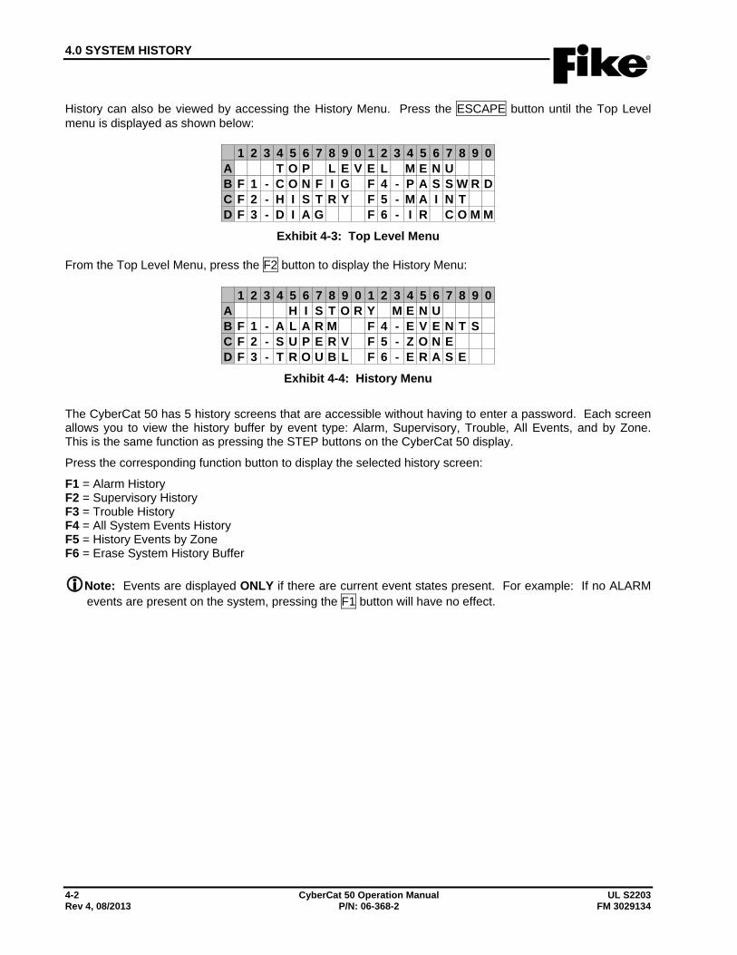
4.0 SYSTEM HISTORY
4-2 CyberCat 50 Operation Manual UL S2203 Rev 4, 08/2013 P/N: 06-368-2 FM 3029134
History can also be viewed by accessing the History Menu. Press the ESCAPE button until the Top Level menu is displayed as shown below:
1 2 3 4 5 6 7 8 9 0 1 2 3 4 5 6 7 8 9 0A T O P L E V E L M E N UB F 1 - C O N F I G F 4 - P A S S W R DC F 2 - H I S T R Y F 5 - M A I N TD F 3 - D I A G F 6 - I R C O M M
Exhibit 4-3: Top Level Menu
From the Top Level Menu, press the F2 button to display the History Menu:
1 2 3 4 5 6 7 8 9 0 1 2 3 4 5 6 7 8 9 0A H I S T O R Y M E N UB F 1 - A L A R M F 4 - E V E N T SC F 2 - S U P E R V F 5 - Z O N ED F 3 - T R O U B L F 6 - E R A S E
Exhibit 4-4: History Menu
The CyberCat 50 has 5 history screens that are accessible without having to enter a password. Each screen allows you to view the history buffer by event type: Alarm, Supervisory, Trouble, All Events, and by Zone. This is the same function as pressing the STEP buttons on the CyberCat 50 display.
Press the corresponding function button to display the selected history screen:
F1 = Alarm History F2 = Supervisory History F3 = Trouble History F4 = All System Events History F5 = History Events by Zone F6 = Erase System History Buffer
Note: Events are displayed ONLY if there are current event states present. For example: If no ALARM events are present on the system, pressing the F1 button will have no effect.
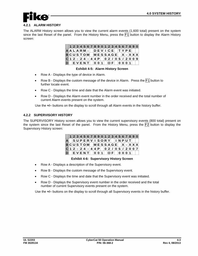
4.0 SYSTEM HISTORY
UL S2203 CyberCat 50 Operation Manual 4-3 FM 3029134 P/N: 06-368-2 Rev 4, 08/2013
4.2.1 ALARM HISTORY The ALARM History screen allows you to view the current alarm events (1,600 total) present on the system since the last Reset of the panel. From the History Menu, press the F1 button to display the Alarm History screen:
1 2 3 4 5 6 7 8 9 0 1 2 3 4 5 6 7 8 9 0A A L A R M : D E V I C E T Y P EB C U S T O M M E S S A G E X - X X XC 1 2 : 2 4 : 4 4 P 0 2 / 0 5 / 2 0 0 9D E V E N T 0 0 1 O F 0 0 0 1
Exhibit 4-5: Alarm History Screen
• Row A - Displays the type of device in Alarm.
• Row B - Displays the custom message of the device in Alarm. Press the F1 button to further locate event.
• Row C - Displays the time and date that the Alarm event was initiated.
• Row D - Displays the Alarm event number in the order received and the total number of current Alarm events present on the system.
Use the +/– buttons on the display to scroll through all Alarm events in the history buffer.
4.2.2 SUPERVISORY HISTORY The SUPERVISORY History screen allows you to view the current supervisory events (800 total) present on the system since the last Reset of the panel. From the History Menu, press the F2 button to display the Supervisory History screen:
1 2 3 4 5 6 7 8 9 0 1 2 3 4 5 6 7 8 9 0A S U P E R V I S O R Y I N P U TB C U S T O M M E S S A G E X - X X XC 1 2 : 2 4 : 4 4 P 0 2 / 0 5 / 2 0 0 7D E V E N T 0 0 1 O F 0 0 0 1
Exhibit 4-6: Supervisory History Screen
• Row A - Displays a description of the Supervisory event.
• Row B - Displays the custom message of the Supervisory event.
• Row C - Displays the time and date that the Supervisory event was initiated.
• Row D - Displays the Supervisory event number in the order received and the total number of current Supervisory events present on the system.
Use the +/– buttons on the display to scroll through all Supervisory events in the history buffer.
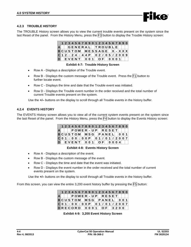
4.0 SYSTEM HISTORY
4-4 CyberCat 50 Operation Manual UL S2203 Rev 4, 08/2013 P/N: 06-368-2 FM 3029134
4.2.3 TROUBLE HISTORY The TROUBLE History screen allows you to view the current trouble events present on the system since the last Reset of the panel. From the History Menu, press the F3 button to display the Trouble History screen:
1 2 3 4 5 6 7 8 9 0 1 2 3 4 5 6 7 8 9 0A G E N E R A L T R O U B L EB C U S T O M M E S S A G E X - X X XC 1 2 : 2 4 : 4 4 P 0 2 / 0 5 / 2 0 0 9D E V E N T 0 0 1 O F 0 0 0 1
Exhibit 4-7: Trouble History Screen
• Row A - Displays a description of the Trouble event.
• Row B - Displays the custom message of the Trouble event. Press the F1 button to further locate event.
• Row C - Displays the time and date that the Trouble event was initiated.
• Row D - Displays the Trouble event number in the order received and the total number of current Trouble events present on the system.
Use the +/– buttons on the display to scroll through all Trouble events in the history buffer.
4.2.4 EVENTS HISTORY The EVENTS History screen allows you to view all of the current system events present on the system since the last Reset of the panel. From the History Menu, press the F4 button to display the Events History screen:
1 2 3 4 5 6 7 8 9 0 1 2 3 4 5 6 7 8 9 0A P O W E R - U P R E S E TB C U S T O M M S G P A N E L 0 0 1C 0 1 : 0 0 : 0 0 P 0 1 / 0 1 / 2 0 0 7D E V E N T 0 0 1 O F 0 0 0 4
Exhibit 4-8: Events History Screen
• Row A - Displays a description of the event. • Row B - Displays the custom message of the event. • Row C - Displays the time and date that the event was initiated. • Row D - Displays the event number in the order received and the total number of current
events present on the system.
Use the +/– buttons on the display to scroll through all Trouble events in the history buffer.
From this screen, you can view the entire 3,200 event history buffer by pressing the F5 button:
1 2 3 4 5 6 7 8 9 0 1 2 3 4 5 6 7 8 9 0A P O W E R - U P R E S E TB C U S T O M M S G P A N E L 0 0 1C 0 1 : 0 0 : 0 0 P 0 1 / 0 1 / 2 0 0 7D R E C O R D 0 0 0 1 O F 3 2 0 0
Exhibit 4-9: 3,200 Event History Screen
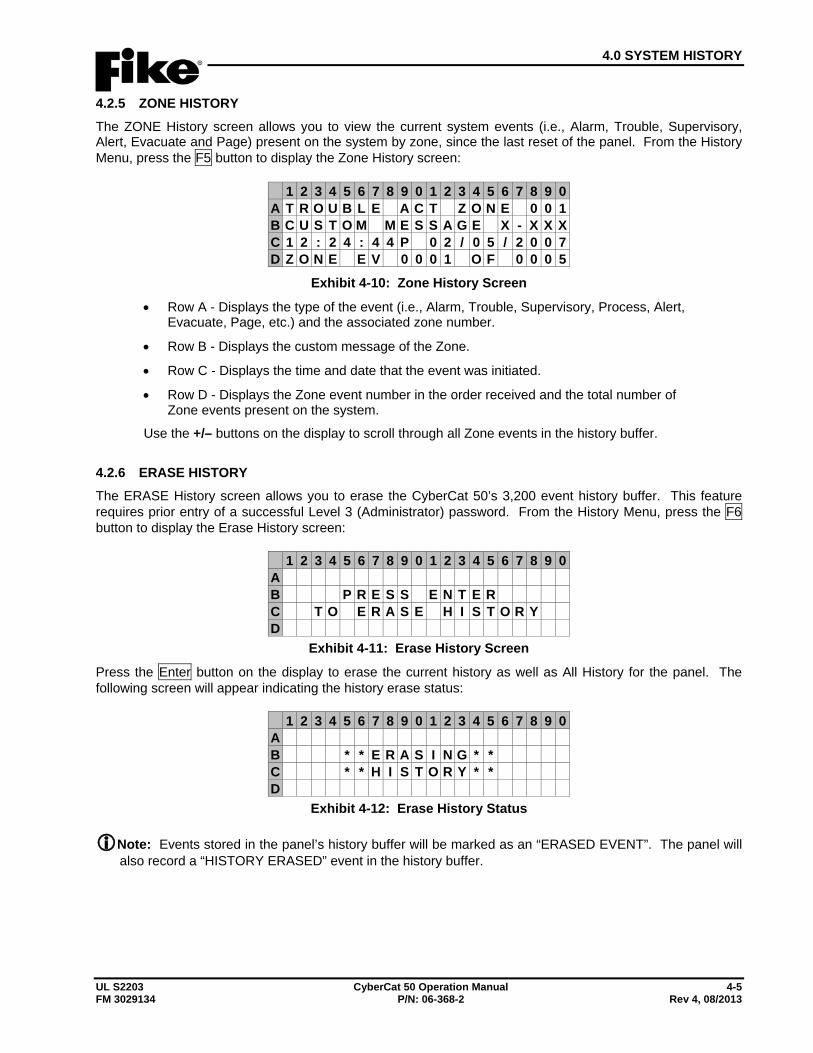
4.0 SYSTEM HISTORY
UL S2203 CyberCat 50 Operation Manual 4-5 FM 3029134 P/N: 06-368-2 Rev 4, 08/2013
4.2.5 ZONE HISTORY The ZONE History screen allows you to view the current system events (i.e., Alarm, Trouble, Supervisory, Alert, Evacuate and Page) present on the system by zone, since the last reset of the panel. From the History Menu, press the F5 button to display the Zone History screen:
1 2 3 4 5 6 7 8 9 0 1 2 3 4 5 6 7 8 9 0A T R O U B L E A C T Z O N E 0 0 1B C U S T O M M E S S A G E X - X X XC 1 2 : 2 4 : 4 4 P 0 2 / 0 5 / 2 0 0 7D Z O N E E V 0 0 0 1 O F 0 0 0 5
Exhibit 4-10: Zone History Screen
• Row A - Displays the type of the event (i.e., Alarm, Trouble, Supervisory, Process, Alert, Evacuate, Page, etc.) and the associated zone number.
• Row B - Displays the custom message of the Zone.
• Row C - Displays the time and date that the event was initiated.
• Row D - Displays the Zone event number in the order received and the total number of Zone events present on the system.
Use the +/– buttons on the display to scroll through all Zone events in the history buffer.
4.2.6 ERASE HISTORY The ERASE History screen allows you to erase the CyberCat 50’s 3,200 event history buffer. This feature requires prior entry of a successful Level 3 (Administrator) password. From the History Menu, press the F6 button to display the Erase History screen:
1 2 3 4 5 6 7 8 9 0 1 2 3 4 5 6 7 8 9 0A B P R E S S E N T E RC T O E R A S E H I S T O R YD
Exhibit 4-11: Erase History Screen
Press the Enter button on the display to erase the current history as well as All History for the panel. The following screen will appear indicating the history erase status:
1 2 3 4 5 6 7 8 9 0 1 2 3 4 5 6 7 8 9 0A B * * E R A S I N G * *C * * H I S T O R Y * *D
Exhibit 4-12: Erase History Status
Note: Events stored in the panel’s history buffer will be marked as an “ERASED EVENT”. The panel will also record a “HISTORY ERASED” event in the history buffer.
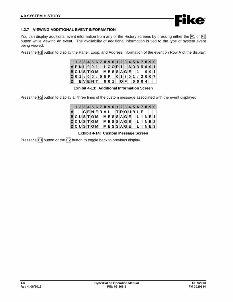
4.0 SYSTEM HISTORY
4-6 CyberCat 50 Operation Manual UL S2203 Rev 4, 08/2013 P/N: 06-368-2 FM 3029134
4.2.7 VIEWING ADDITIONAL EVENT INFORMATION
You can display additional event information from any of the History screens by pressing either the F1 or F2 button while viewing an event. The availability of additional information is tied to the type of system event being viewed.
Press the F1 button to display the Panel, Loop, and Address information of the event on Row A of the display:
1 2 3 4 5 6 7 8 9 0 1 2 3 4 5 6 7 8 9 0A P N L 0 0 1 L O O P 1 A D D R 0 0 1B C U S T O M M E S S A G E 1 - 0 0 1C 0 1 : 0 0 : 0 0 P 0 1 / 0 1 / 2 0 0 7D E V E N T 0 0 1 O F 0 0 0 4
Exhibit 4-13: Additional Information Screen
Press the F2 button to display all three lines of the custom message associated with the event displayed:
1 2 3 4 5 6 7 8 9 0 1 2 3 4 5 6 7 8 9 0A G E N E R A L T R O U B L EB C U S T O M M E S S A G E L I N E 1C C U S T O M M E S S A G E L I N E 2D C U S T O M M E S S A G E L I N E 3
Exhibit 4-14: Custom Message Screen
Press the F1 button or the F2 button to toggle back to previous display.
5.0 SYSTEM DIAGNOSTICS
UL S2203 CyberCat 50 Operation Manual 5-1 FM 3029134 P/N: 06-368-2 Rev 4, 08/2013
5.1 OVERVIEW Problems with the CyberCat 50 system can generally be classified into two categories: programming problems and hardware (including hardware) problems. Normally hardware problems are annunciated on the CyberCat 50 system display. Programming problems are typically identified when the system operates incorrectly in response to a system event.
The CyberCat 50’s Diagnostics Menus are designed to assist the service technician in isolating and correcting hardware faults with the system. The Service of the CyberCat 50 system shall be performed solely by factory certified and qualified technicians that possess a complete understanding of the system hardware and functions.
5.2 DIAGNOSING PROBLEMS Hardware problems with the system can be isolated to the panel or field devices by removing all field wiring and installing the circuit end-of-line resistor directly on the control board or module. Once you have isolated the cause of the problem (main board or field device), you can use the diagnostic menu features to further identify the problem. The CyberCat 50 system controller utilizes surface mount technology (SMT) for easy installation and maintenance. SMT prohibits component-level field repairs.
5.3 REMOVING OR REPLACING PANEL COMPONENTS If it is determined that a panel component is defective and needs to be replaced:
1. First, use the system programming software to download the current system configuration from the panel.
2. Disconnect the system batteries then remove AC power.
I Caution: Removing or replacing system components when power is applied will damage the equipment.
3. Disconnect field wiring from component(s). The majority of the CyberCat 50 system components have removable terminals to facilitate connection of field wiring.
4. Remove and replace the defective system component(s) following the installation instructions supplied with the component(s).
I Caution: The CyberCat 50 components and field devices contain static sensitive components. Handle the electronics by the edges only and avoid touching the integrated components. Keep all electronics in the protective anti-static bag it was shipped in until time for installation. Always ground yourself with a proper wrist strap before handling the module(s). If the installer is properly grounded at all times, damage due to static discharge will not occur. If the module requires repair or return to Fike, it must be shipped in an anti-static bag.
5. Reapply power to the system by reconnecting AC power then connecting system batteries.
6. Verify proper operation of replaced component(s) before connecting field wiring.
7. Reconnect all field wiring.
8. Functionally test the operation of the system to verify proper operation.
5.0 SYSTEM DIAGNOSTICS
5-2 CyberCat 50 Operation Manual UL S2203 Rev 4, 08/2013 P/N: 06-368-2 FM 3029134
5.4 REMOVING OR REPLACING FIELD DEVICES If it is determined that a field device is defective and needs to be replaced:
1. First, use the system programming software to download the current system configuration from the panel.
2. Disconnect the system batteries then remove AC power.
I Caution: Removing or replacing field devices when power is applied could damage the equipment.
3. Disconnect field wiring from field device(s).
4. Remove and replace the defective field device(s) following the installation instructions supplied with the device(s).
I Caution: The CyberCat 50 field devices contain static sensitive components. Handle the electronics by the edges only and avoid touching the integrated components. Keep all electronics in the protective static bags it was shipped in until time for installation. Always ground yourself with a proper wrist strap before handling the module(s). If the installer is properly grounded at all times, damage due to static discharge will not occur. If the module requires repair or return to Fike, it must be shipped in an anti-static bag.
5. Reapply power to the system by reconnecting AC power then connecting system batteries.
6. Reconnect all field wiring.
7. Resend configuration to device(s), if applicable.
8. Functionally test the operation of the system to verify proper operation.
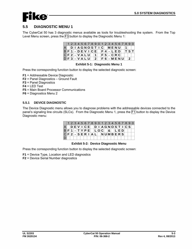
5.0 SYSTEM DIAGNOSTICS
UL S2203 CyberCat 50 Operation Manual 5-3 FM 3029134 P/N: 06-368-2 Rev 4, 08/2013
5.5 DIAGNOSTIC MENU 1 The CyberCat 50 has 3 diagnostic menus available as tools for troubleshooting the system. From the Top Level Menu screen, press the F3 button to display the Diagnostic Menu 1:
1 2 3 4 5 6 7 8 9 0 1 2 3 4 5 6 7 8 9 0A D I A G N O S T I C M E N U 1B F 1 - D E V I C E F 4 - L E D T S TC F 2 - V A L U 1 F 5 - C R CD F 3 - V A L U 2 F 6 - M E N U 2
Exhibit 5-1: Diagnostic Menu 1 Press the corresponding function button to display the selected diagnostic screen:
F1 = Addressable Device Diagnostic F2 = Panel Diagnostics – Ground Fault F3 = Panel Diagnostics F4 = LED Test F5 = Main Board Processor Communications F6 = Diagnostics Menu 2
5.5.1 DEVICE DIAGNOSTIC The Device Diagnostic menu allows you to diagnose problems with the addressable devices connected to the panel’s signaling line circuits (SLCs). From the Diagnostic Menu 1, press the F1 button to display the Device Diagnostic menu:
1 2 3 4 5 6 7 8 9 0 1 2 3 4 5 6 7 8 9 0A D E V I C E D I A G N O S T I C SB F 1 - T Y P E L O C & L E DC F 2 - S E R I A L N U M B E R SD
Exhibit 5-2: Device Diagnostic Menu Press the corresponding function button to display the selected diagnostic screen:
F1 = Device Type, Location and LED diagnostics F2 = Device Serial Number diagnostics

5.0 SYSTEM DIAGNOSTICS
5-4 CyberCat 50 Operation Manual UL S2203 Rev 4, 08/2013 P/N: 06-368-2 FM 3029134
5.5.1.1 DEVICE TYPE, LOCATION AND LED DIAGNOSTICS The Device Type Diagnostic screen allows you to compare the type of addressable device held in the panel’s configuration at a specific address to the type of device present/found on the signaling line circuit (SLC). From the Device Diagnostic Menu, press the F1 button to display the Device Loc & LED Diagnostic screen:
1 2 3 4 5 6 7 8 9 0 1 2 3 4 5 6 7 8 9 0A L O O P : N A D R : 0 0 1 - 0 2 0 DB 1 2 3 4 5 6 7 8 9 0 1 2 3 4 5 6 7 8 9 0C C O N F I G U R E D D E V T Y P ED P R E S E N T D E V I C E T Y P E
Exhibit 5-3: Device Type Diagnostic Screen
• Row A (LOOP) - Allows you to select the loop number, represented by ‘N’. Use the ◄► buttons to position the cursor under the field; then press the +/- buttons to change to desired loop (CyberCat 50 has only 1 loop).
• Row A (ADR) - Allows you to select the address range to display in groups of 20. Use the ◄► buttons to position the cursor under the first digits (001 in this case); then press the +/- buttons to increment/decrement the group selection
• Row A (D) - Allows you to toggle between D or L:
D - Displays the device types in Rows C and D.
L – Allows you to light the LED for the device (red/green flash). To light the device LED, use the ◄► buttons to position the cursor under the field; then use the +/- buttons to set field to L. Then use the ◄► buttons to position the cursor under the desired address on Row D. Toggle the LED status by pressing the +/- button at the specific address location.
• Row B - These numbers act as placeholders for the range of addresses selected in Row A.
• Row C - Displays the type of device programmed in the configuration for the specific address displayed:
P = Photo H = Heat F = FAAST D = DUCT M = Monitor, 4” - = Unknown Y = Relay m = Mini Monitor U = Photo/Heat I = Ion T = Pull Station 2 = Dual Monitor C = Control Z = Conventional Zone
• Row D - Displays the type of device present/found connected on the addressable loop at the specific address displayed. Same device types as shown in Row C description above.
Note: The panel loads this screen upon reset and does not provide live updates as loop changes are made. Therefore, the panel must be reset in order to update this screen if wiring or SLC status is modified.
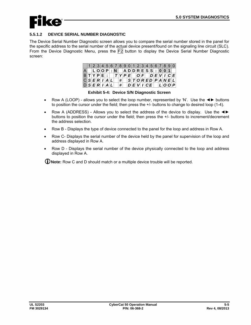
5.0 SYSTEM DIAGNOSTICS
UL S2203 CyberCat 50 Operation Manual 5-5 FM 3029134 P/N: 06-368-2 Rev 4, 08/2013
5.5.1.2 DEVICE SERIAL NUMBER DIAGNOSTIC The Device Serial Number Diagnostic screen allows you to compare the serial number stored in the panel for the specific address to the serial number of the actual device present/found on the signaling line circuit (SLC). From the Device Diagnostic Menu, press the F2 button to display the Device Serial Number Diagnostic screen:
1 2 3 4 5 6 7 8 9 0 1 2 3 4 5 6 7 8 9 0A L O O P : N A D D R E S S : 0 0 1B T Y P E : T Y P E O F D E V I C EC S E R I A L # S T O R E D P A N E LD S E R I A L # D E V I C E L O O P
Exhibit 5-4: Device S/N Diagnostic Screen
• Row A (LOOP) - allows you to select the loop number, represented by ‘N’. Use the ◄► buttons to position the cursor under the field; then press the +/- buttons to change to desired loop (1-4).
• Row A (ADDRESS) - Allows you to select the address of the device to display. Use the ◄► buttons to position the cursor under the field; then press the +/- buttons to increment/decrement the address selection.
• Row B - Displays the type of device connected to the panel for the loop and address in Row A.
• Row C- Displays the serial number of the device held by the panel for supervision of the loop and address displayed in Row A.
• Row D - Displays the serial number of the device physically connected to the loop and address displayed in Row A.
Note: Row C and D should match or a multiple device trouble will be reported.
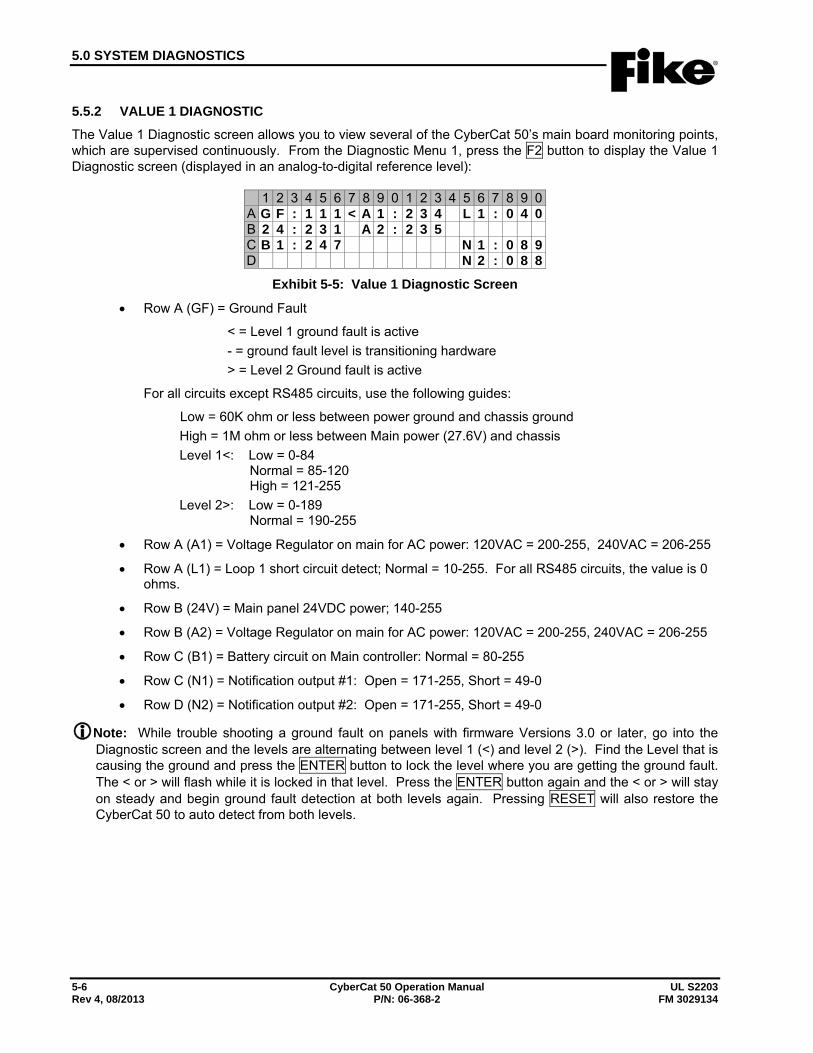
5.0 SYSTEM DIAGNOSTICS
5-6 CyberCat 50 Operation Manual UL S2203 Rev 4, 08/2013 P/N: 06-368-2 FM 3029134
5.5.2 VALUE 1 DIAGNOSTIC The Value 1 Diagnostic screen allows you to view several of the CyberCat 50’s main board monitoring points, which are supervised continuously. From the Diagnostic Menu 1, press the F2 button to display the Value 1 Diagnostic screen (displayed in an analog-to-digital reference level):
1 2 3 4 5 6 7 8 9 0 1 2 3 4 5 6 7 8 9 0A G F : 1 1 1 < A 1 : 2 3 4 L 1 : 0 4 0B 2 4 : 2 3 1 A 2 : 2 3 5C B 1 : 2 4 7 N 1 : 0 8 9D N 2 : 0 8 8
Exhibit 5-5: Value 1 Diagnostic Screen
• Row A (GF) = Ground Fault
< = Level 1 ground fault is active - = ground fault level is transitioning hardware > = Level 2 Ground fault is active
For all circuits except RS485 circuits, use the following guides:
Low = 60K ohm or less between power ground and chassis ground High = 1M ohm or less between Main power (27.6V) and chassis Level 1<: Low = 0-84 Normal = 85-120 High = 121-255 Level 2>: Low = 0-189 Normal = 190-255
• Row A (A1) = Voltage Regulator on main for AC power: 120VAC = 200-255, 240VAC = 206-255
• Row A (L1) = Loop 1 short circuit detect; Normal = 10-255. For all RS485 circuits, the value is 0 ohms.
• Row B (24V) = Main panel 24VDC power; 140-255
• Row B (A2) = Voltage Regulator on main for AC power: 120VAC = 200-255, 240VAC = 206-255
• Row C (B1) = Battery circuit on Main controller: Normal = 80-255
• Row C (N1) = Notification output #1: Open = 171-255, Short = 49-0
• Row D (N2) = Notification output #2: Open = 171-255, Short = 49-0
Note: While trouble shooting a ground fault on panels with firmware Versions 3.0 or later, go into the Diagnostic screen and the levels are alternating between level 1 (<) and level 2 (>). Find the Level that is causing the ground and press the ENTER button to lock the level where you are getting the ground fault. The < or > will flash while it is locked in that level. Press the ENTER button again and the < or > will stay on steady and begin ground fault detection at both levels again. Pressing RESET will also restore the CyberCat 50 to auto detect from both levels.
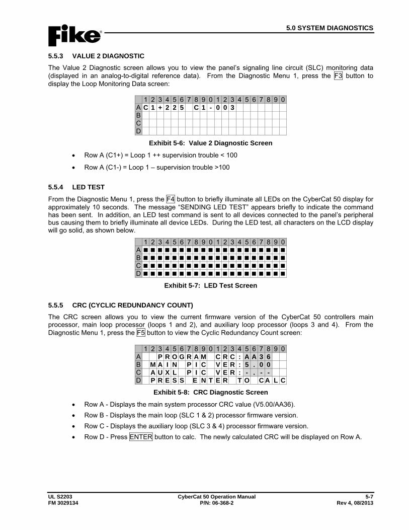
5.0 SYSTEM DIAGNOSTICS
UL S2203 CyberCat 50 Operation Manual 5-7 FM 3029134 P/N: 06-368-2 Rev 4, 08/2013
5.5.3 VALUE 2 DIAGNOSTIC The Value 2 Diagnostic screen allows you to view the panel’s signaling line circuit (SLC) monitoring data (displayed in an analog-to-digital reference data). From the Diagnostic Menu 1, press the F3 button to display the Loop Monitoring Data screen:
1 2 3 4 5 6 7 8 9 0 1 2 3 4 5 6 7 8 9 0A C 1 + 2 2 5 C 1 - 0 0 3 B C D
Exhibit 5-6: Value 2 Diagnostic Screen
• Row A (C1+) = Loop 1 ++ supervision trouble < 100
• Row A (C1-) = Loop 1 – supervision trouble >100
5.5.4 LED TEST
From the Diagnostic Menu 1, press the F4 button to briefly illuminate all LEDs on the CyberCat 50 display for approximately 10 seconds. The message “SENDING LED TEST” appears briefly to indicate the command has been sent. In addition, an LED test command is sent to all devices connected to the panel’s peripheral bus causing them to briefly illuminate all device LEDs. During the LED test, all characters on the LCD display will go solid, as shown below.
1 2 3 4 5 6 7 8 9 0 1 2 3 4 5 6 7 8 9 0A B C D
Exhibit 5-7: LED Test Screen
5.5.5 CRC (CYCLIC REDUNDANCY COUNT) The CRC screen allows you to view the current firmware version of the CyberCat 50 controllers main processor, main loop processor (loops 1 and 2), and auxiliary loop processor (loops 3 and 4). From the Diagnostic Menu 1, press the F5 button to view the Cyclic Redundancy Count screen:
1 2 3 4 5 6 7 8 9 0 1 2 3 4 5 6 7 8 9 0A P R O G R A M C R C : A A 3 6B M A I N P I C V E R : 5 . 0 0C A U X L P I C V E R : - . - -D P R E S S E N T E R T O C A L C
Exhibit 5-8: CRC Diagnostic Screen
• Row A - Displays the main system processor CRC value (V5.00/AA36). • Row B - Displays the main loop (SLC 1 & 2) processor firmware version. • Row C - Displays the auxiliary loop (SLC 3 & 4) processor firmware version. • Row D - Press ENTER button to calc. The newly calculated CRC will be displayed on Row A.
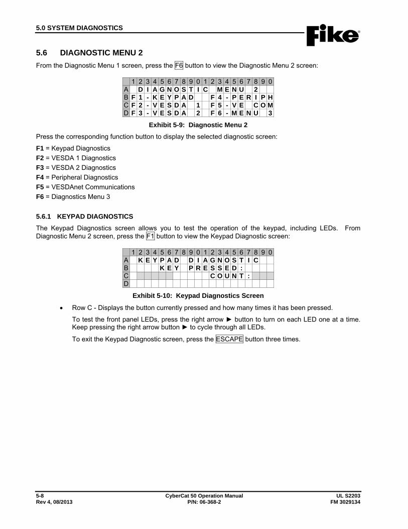
5.0 SYSTEM DIAGNOSTICS
5-8 CyberCat 50 Operation Manual UL S2203 Rev 4, 08/2013 P/N: 06-368-2 FM 3029134
5.6 DIAGNOSTIC MENU 2 From the Diagnostic Menu 1 screen, press the F6 button to view the Diagnostic Menu 2 screen:
1 2 3 4 5 6 7 8 9 0 1 2 3 4 5 6 7 8 9 0A D I A G N O S T I C M E N U 2B F 1 - K E Y P A D F 4 - P E R I P HC F 2 - V E S D A 1 F 5 - V E C O MD F 3 - V E S D A 2 F 6 - M E N U 3
Exhibit 5-9: Diagnostic Menu 2 Press the corresponding function button to display the selected diagnostic screen:
F1 = Keypad Diagnostics F2 = VESDA 1 Diagnostics F3 = VESDA 2 Diagnostics F4 = Peripheral Diagnostics F5 = VESDAnet Communications F6 = Diagnostics Menu 3
5.6.1 KEYPAD DIAGNOSTICS The Keypad Diagnostics screen allows you to test the operation of the keypad, including LEDs. From Diagnostic Menu 2 screen, press the F1 button to view the Keypad Diagnostic screen:
1 2 3 4 5 6 7 8 9 0 1 2 3 4 5 6 7 8 9 0A K E Y P A D D I A G N O S T I CB K E Y P R E S S E D :C C O U N T :D
Exhibit 5-10: Keypad Diagnostics Screen
• Row C - Displays the button currently pressed and how many times it has been pressed.
To test the front panel LEDs, press the right arrow ► button to turn on each LED one at a time. Keep pressing the right arrow button ► to cycle through all LEDs.
To exit the Keypad Diagnostic screen, press the ESCAPE button three times.
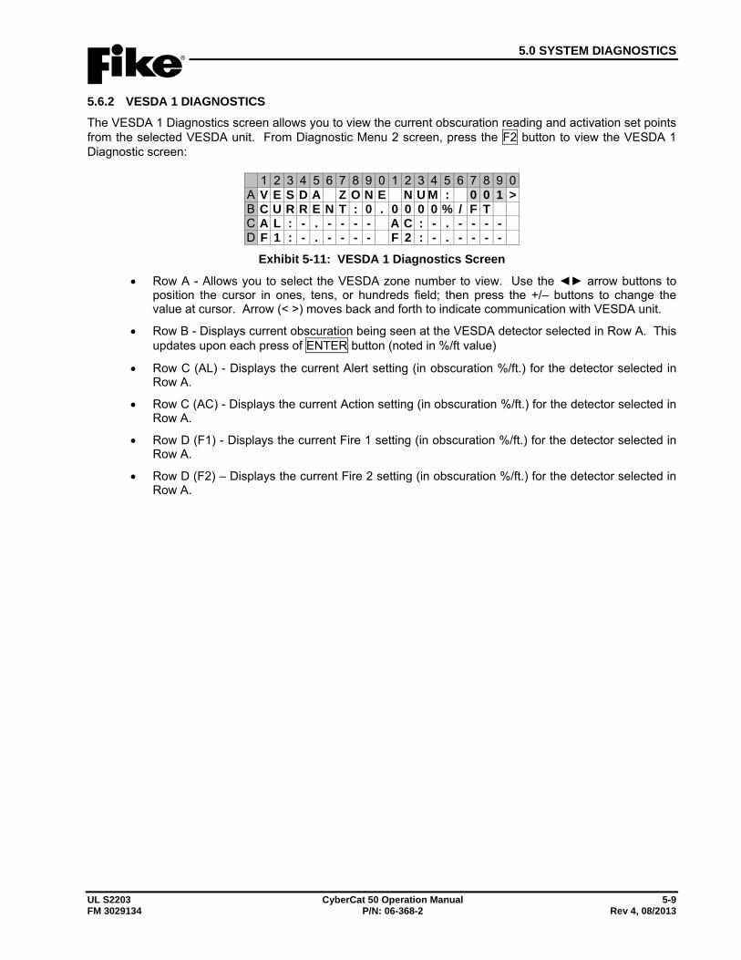
5.0 SYSTEM DIAGNOSTICS
UL S2203 CyberCat 50 Operation Manual 5-9 FM 3029134 P/N: 06-368-2 Rev 4, 08/2013
5.6.2 VESDA 1 DIAGNOSTICS The VESDA 1 Diagnostics screen allows you to view the current obscuration reading and activation set points from the selected VESDA unit. From Diagnostic Menu 2 screen, press the F2 button to view the VESDA 1 Diagnostic screen:
1 2 3 4 5 6 7 8 9 0 1 2 3 4 5 6 7 8 9 0A V E S D A Z O N E N U M : 0 0 1 >B C U R R E N T : 0 . 0 0 0 0 % / F TC A L : - . - - - - A C : - . - - - -D F 1 : - . - - - - F 2 : - . - - - -
Exhibit 5-11: VESDA 1 Diagnostics Screen
• Row A - Allows you to select the VESDA zone number to view. Use the ◄► arrow buttons to position the cursor in ones, tens, or hundreds field; then press the +/– buttons to change the value at cursor. Arrow (< >) moves back and forth to indicate communication with VESDA unit.
• Row B - Displays current obscuration being seen at the VESDA detector selected in Row A. This updates upon each press of ENTER button (noted in %/ft value)
• Row C (AL) - Displays the current Alert setting (in obscuration %/ft.) for the detector selected in Row A.
• Row C (AC) - Displays the current Action setting (in obscuration %/ft.) for the detector selected in Row A.
• Row D (F1) - Displays the current Fire 1 setting (in obscuration %/ft.) for the detector selected in Row A.
• Row D (F2) – Displays the current Fire 2 setting (in obscuration %/ft.) for the detector selected in Row A.
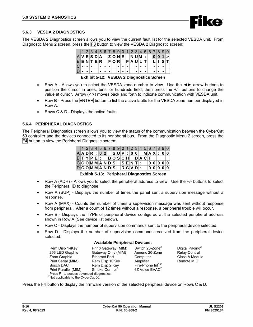
5.0 SYSTEM DIAGNOSTICS
5-10 CyberCat 50 Operation Manual UL S2203 Rev 4, 08/2013 P/N: 06-368-2 FM 3029134
5.6.3 VESDA 2 DIAGNOSTICS The VESDA 2 Diagnostics screen allows you to view the current fault list for the selected VESDA unit. From Diagnostic Menu 2 screen, press the F3 button to view the VESDA 2 Diagnostic screen:
1 2 3 4 5 6 7 8 9 0 1 2 3 4 5 6 7 8 9 0A V E S D A Z O N E N U M : 0 0 1 >B E N T E R F O R F A U L T L I S TC - - - - - - - - - - - - - - -D - - - - - - - - - - - - - - -
Exhibit 5-12: VESDA 2 Diagnostics Screen
• Row A - Allows you to select the VESDA zone number to view. Use the ◄► arrow buttons to position the cursor in ones, tens, or hundreds field; then press the +/– buttons to change the value at cursor. Arrow (< >) moves back and forth to indicate communication with VESDA unit.
• Row B - Press the ENTER button to list the active faults for the VESDA zone number displayed in Row A.
• Rows C & D - Displays the active faults.
5.6.4 PERIPHERAL DIAGNOSTICS The Peripheral Diagnostics screen allows you to view the status of the communication between the CyberCat 50 controller and the devices connected to its peripheral bus. From the Diagnostic Menu 2 screen, press the F4 button to view the Peripheral Diagnostic screen:
1 2 3 4 5 6 7 8 9 0 1 2 3 4 5 6 7 8 9 0A A D R : 0 2 S U P : 0 0 M A X : 0 0B T Y P E : B O S C H D A C TC C O M M A N D S S E N T : 0 0 0 0 0D C O M M A N D S R C V D : 0 0 0 0 0
Exhibit 5-13: Peripheral Diagnostics Screen
• Row A (ADR) - Allows you to select the peripheral address to view. Use the +/- buttons to select the Peripheral ID to diagnose.
• Row A (SUP) - Displays the number of times the panel sent a supervision message without a response.
• Row A (MAX) - Counts the number of times a supervision message was sent without response from peripheral. After a count of 12 times without a response, a peripheral trouble will occur.
• Row B - Displays the TYPE of peripheral device configured at the selected peripheral address shown in Row A (See device list below).
• Row C - Displays the number of supervision commands sent to the peripheral device selected. • Row D - Displays the number of supervision commands received from the peripheral device
selected. Available Peripheral Devices:
Rem Disp 14Key Print+Gateway (MIM) Switch 20-Zone2 Digital Paging2 256 LED Graphic Gateway Only (MIM) Annunc 20-Zone Relay Control Zone Graphic Ethernet Port Computer Class A Module Print Serial (MIM) Rem Disp 10Key Amplifier Remote MIC Bosch DACT Rem Disp 2 Key Fire-Phone Int1,2 Print Parallel (MIM) Smoke Control2 6Z Voice EVAC2
1Press F1 to access advanced diagnostics. 2Not applicable to the CyberCat 50.
Press the F4 button to display the firmware version of the selected peripheral device on Rows C & D.
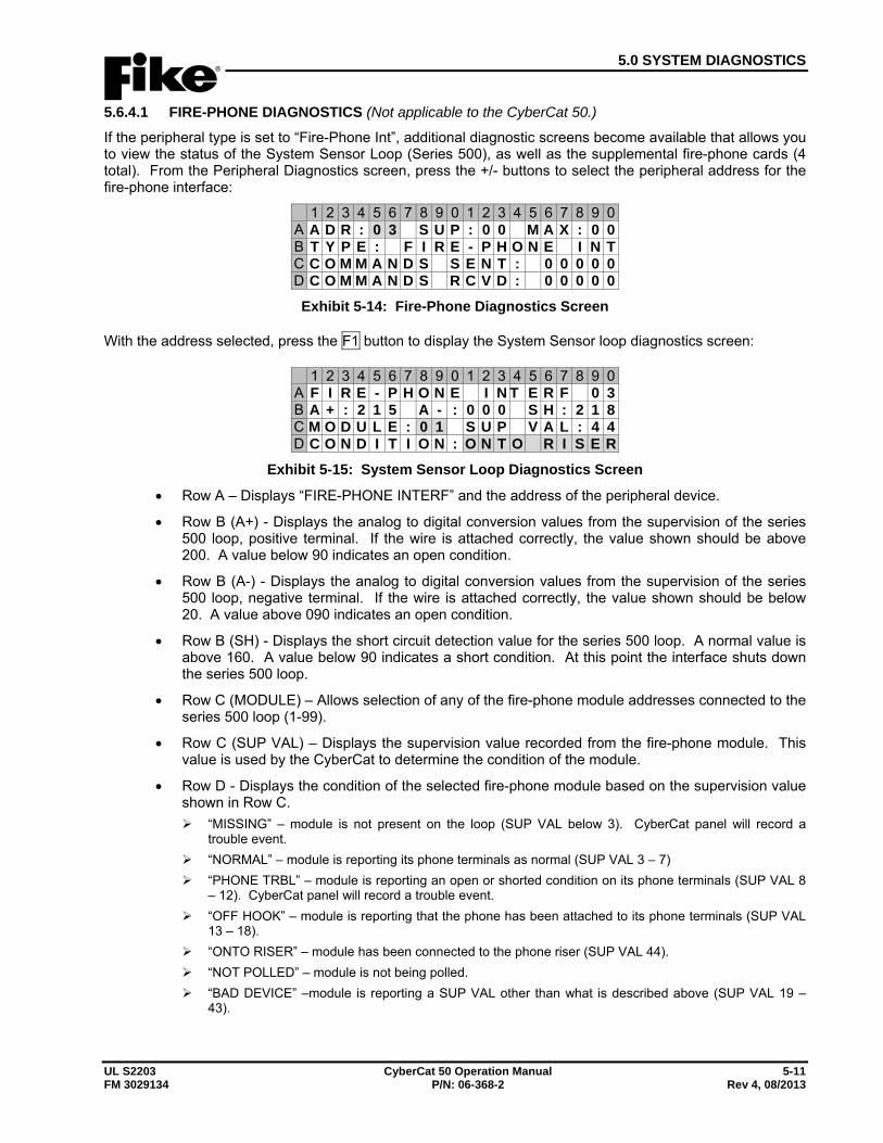
5.0 SYSTEM DIAGNOSTICS
UL S2203 CyberCat 50 Operation Manual 5-11 FM 3029134 P/N: 06-368-2 Rev 4, 08/2013
5.6.4.1 FIRE-PHONE DIAGNOSTICS (Not applicable to the CyberCat 50.) If the peripheral type is set to “Fire-Phone Int”, additional diagnostic screens become available that allows you to view the status of the System Sensor Loop (Series 500), as well as the supplemental fire-phone cards (4 total). From the Peripheral Diagnostics screen, press the +/- buttons to select the peripheral address for the fire-phone interface:
1 2 3 4 5 6 7 8 9 0 1 2 3 4 5 6 7 8 9 0A A D R : 0 3 S U P : 0 0 M A X : 0 0B T Y P E : F I R E - P H O N E I N TC C O M M A N D S S E N T : 0 0 0 0 0D C O M M A N D S R C V D : 0 0 0 0 0
Exhibit 5-14: Fire-Phone Diagnostics Screen
With the address selected, press the F1 button to display the System Sensor loop diagnostics screen:
1 2 3 4 5 6 7 8 9 0 1 2 3 4 5 6 7 8 9 0A F I R E - P H O N E I N T E R F 0 3B A + : 2 1 5 A - : 0 0 0 S H : 2 1 8C M O D U L E : 0 1 S U P V A L : 4 4D C O N D I T I O N : O N T O R I S E R
Exhibit 5-15: System Sensor Loop Diagnostics Screen
• Row A – Displays “FIRE-PHONE INTERF” and the address of the peripheral device.
• Row B (A+) - Displays the analog to digital conversion values from the supervision of the series 500 loop, positive terminal. If the wire is attached correctly, the value shown should be above 200. A value below 90 indicates an open condition.
• Row B (A-) - Displays the analog to digital conversion values from the supervision of the series 500 loop, negative terminal. If the wire is attached correctly, the value shown should be below 20. A value above 090 indicates an open condition.
• Row B (SH) - Displays the short circuit detection value for the series 500 loop. A normal value is above 160. A value below 90 indicates a short condition. At this point the interface shuts down the series 500 loop.
• Row C (MODULE) – Allows selection of any of the fire-phone module addresses connected to the series 500 loop (1-99).
• Row C (SUP VAL) – Displays the supervision value recorded from the fire-phone module. This value is used by the CyberCat to determine the condition of the module.
• Row D - Displays the condition of the selected fire-phone module based on the supervision value shown in Row C.
“MISSING” – module is not present on the loop (SUP VAL below 3). CyberCat panel will record a trouble event.
“NORMAL” – module is reporting its phone terminals as normal (SUP VAL 3 – 7) “PHONE TRBL” – module is reporting an open or shorted condition on its phone terminals (SUP VAL 8
– 12). CyberCat panel will record a trouble event. “OFF HOOK” – module is reporting that the phone has been attached to its phone terminals (SUP VAL
13 – 18). “ONTO RISER” – module has been connected to the phone riser (SUP VAL 44). “NOT POLLED” – module is not being polled. “BAD DEVICE” –module is reporting a SUP VAL other than what is described above (SUP VAL 19 –
43).
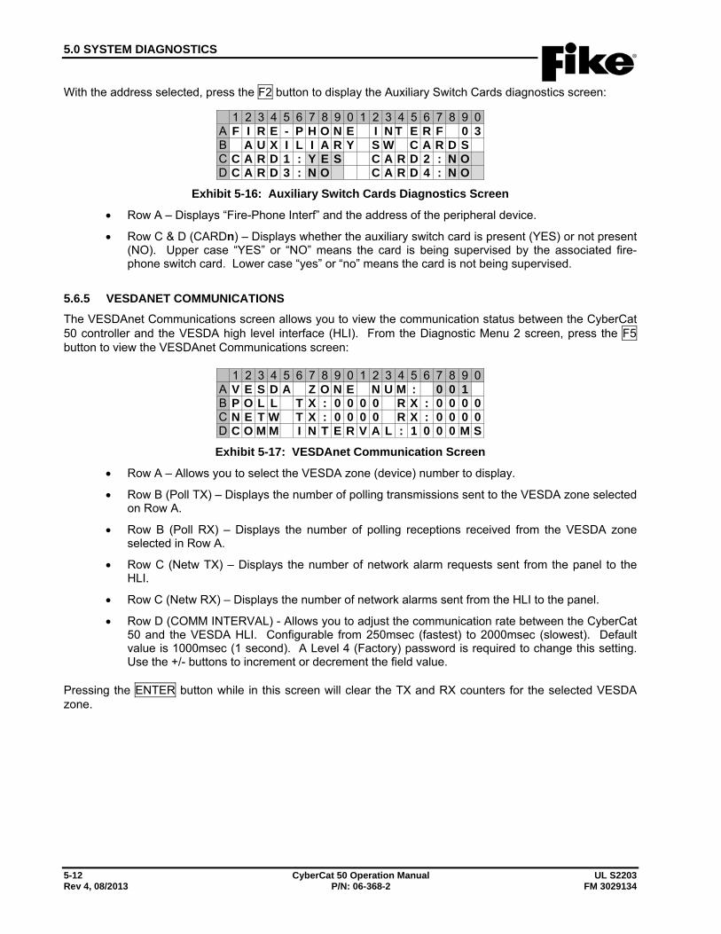
5.0 SYSTEM DIAGNOSTICS
5-12 CyberCat 50 Operation Manual UL S2203 Rev 4, 08/2013 P/N: 06-368-2 FM 3029134
With the address selected, press the F2 button to display the Auxiliary Switch Cards diagnostics screen:
1 2 3 4 5 6 7 8 9 0 1 2 3 4 5 6 7 8 9 0A F I R E - P H O N E I N T E R F 0 3B A U X I L I A R Y S W C A R D SC C A R D 1 : Y E S C A R D 2 : N OD C A R D 3 : N O C A R D 4 : N O
Exhibit 5-16: Auxiliary Switch Cards Diagnostics Screen
• Row A – Displays “Fire-Phone Interf” and the address of the peripheral device.
• Row C & D (CARDn) – Displays whether the auxiliary switch card is present (YES) or not present (NO). Upper case “YES” or “NO” means the card is being supervised by the associated fire-phone switch card. Lower case “yes” or “no” means the card is not being supervised.
5.6.5 VESDANET COMMUNICATIONS The VESDAnet Communications screen allows you to view the communication status between the CyberCat 50 controller and the VESDA high level interface (HLI). From the Diagnostic Menu 2 screen, press the F5 button to view the VESDAnet Communications screen:
1 2 3 4 5 6 7 8 9 0 1 2 3 4 5 6 7 8 9 0A V E S D A Z O N E N U M : 0 0 1B P O L L T X : 0 0 0 0 R X : 0 0 0 0C N E T W T X : 0 0 0 0 R X : 0 0 0 0D C O M M I N T E R V A L : 1 0 0 0 M S
Exhibit 5-17: VESDAnet Communication Screen
• Row A – Allows you to select the VESDA zone (device) number to display.
• Row B (Poll TX) – Displays the number of polling transmissions sent to the VESDA zone selected on Row A.
• Row B (Poll RX) – Displays the number of polling receptions received from the VESDA zone selected in Row A.
• Row C (Netw TX) – Displays the number of network alarm requests sent from the panel to the HLI.
• Row C (Netw RX) – Displays the number of network alarms sent from the HLI to the panel.
• Row D (COMM INTERVAL) - Allows you to adjust the communication rate between the CyberCat 50 and the VESDA HLI. Configurable from 250msec (fastest) to 2000msec (slowest). Default value is 1000msec (1 second). A Level 4 (Factory) password is required to change this setting. Use the +/- buttons to increment or decrement the field value.
Pressing the ENTER button while in this screen will clear the TX and RX counters for the selected VESDA zone.
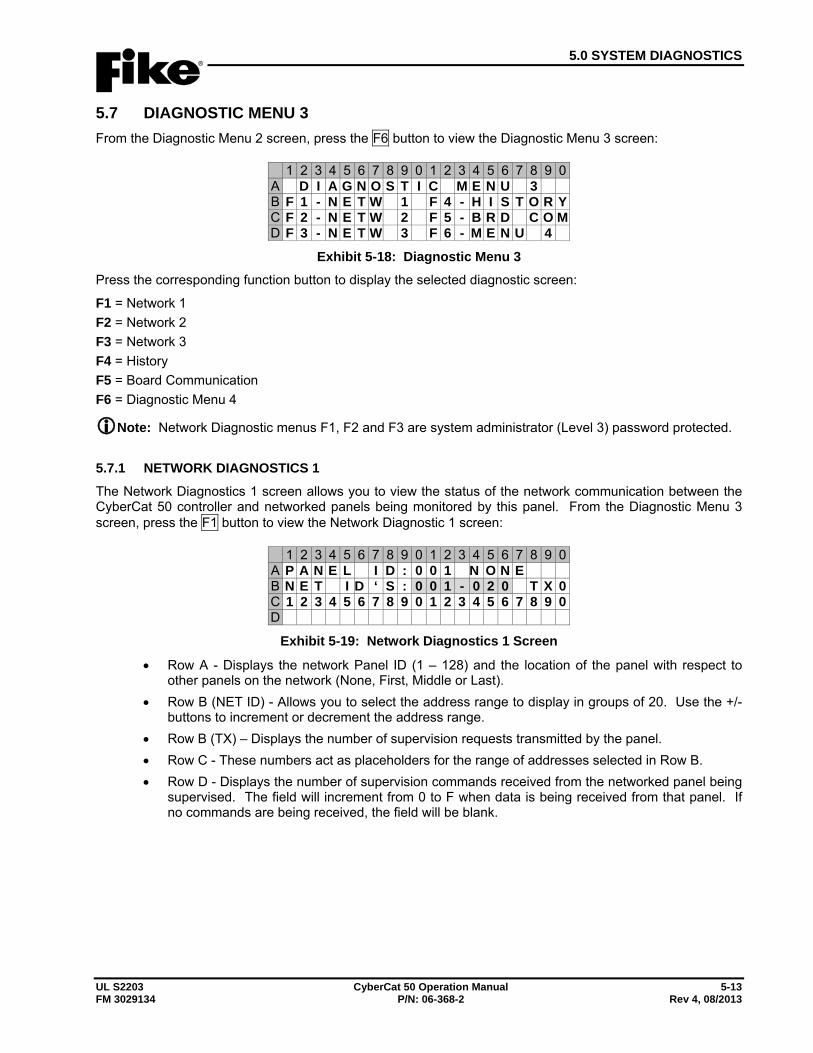
5.0 SYSTEM DIAGNOSTICS
UL S2203 CyberCat 50 Operation Manual 5-13 FM 3029134 P/N: 06-368-2 Rev 4, 08/2013
5.7 DIAGNOSTIC MENU 3 From the Diagnostic Menu 2 screen, press the F6 button to view the Diagnostic Menu 3 screen:
1 2 3 4 5 6 7 8 9 0 1 2 3 4 5 6 7 8 9 0A D I A G N O S T I C M E N U 3B F 1 - N E T W 1 F 4 - H I S T O R YC F 2 - N E T W 2 F 5 - B R D C O MD F 3 - N E T W 3 F 6 - M E N U 4
Exhibit 5-18: Diagnostic Menu 3 Press the corresponding function button to display the selected diagnostic screen:
F1 = Network 1 F2 = Network 2 F3 = Network 3 F4 = History F5 = Board Communication F6 = Diagnostic Menu 4
Note: Network Diagnostic menus F1, F2 and F3 are system administrator (Level 3) password protected.
5.7.1 NETWORK DIAGNOSTICS 1 The Network Diagnostics 1 screen allows you to view the status of the network communication between the CyberCat 50 controller and networked panels being monitored by this panel. From the Diagnostic Menu 3 screen, press the F1 button to view the Network Diagnostic 1 screen:
1 2 3 4 5 6 7 8 9 0 1 2 3 4 5 6 7 8 9 0A P A N E L I D : 0 0 1 N O N EB N E T I D ‘ S : 0 0 1 - 0 2 0 T X 0C 1 2 3 4 5 6 7 8 9 0 1 2 3 4 5 6 7 8 9 0D
Exhibit 5-19: Network Diagnostics 1 Screen
• Row A - Displays the network Panel ID (1 – 128) and the location of the panel with respect to other panels on the network (None, First, Middle or Last).
• Row B (NET ID) - Allows you to select the address range to display in groups of 20. Use the +/- buttons to increment or decrement the address range.
• Row B (TX) – Displays the number of supervision requests transmitted by the panel. • Row C - These numbers act as placeholders for the range of addresses selected in Row B. • Row D - Displays the number of supervision commands received from the networked panel being
supervised. The field will increment from 0 to F when data is being received from that panel. If no commands are being received, the field will be blank.
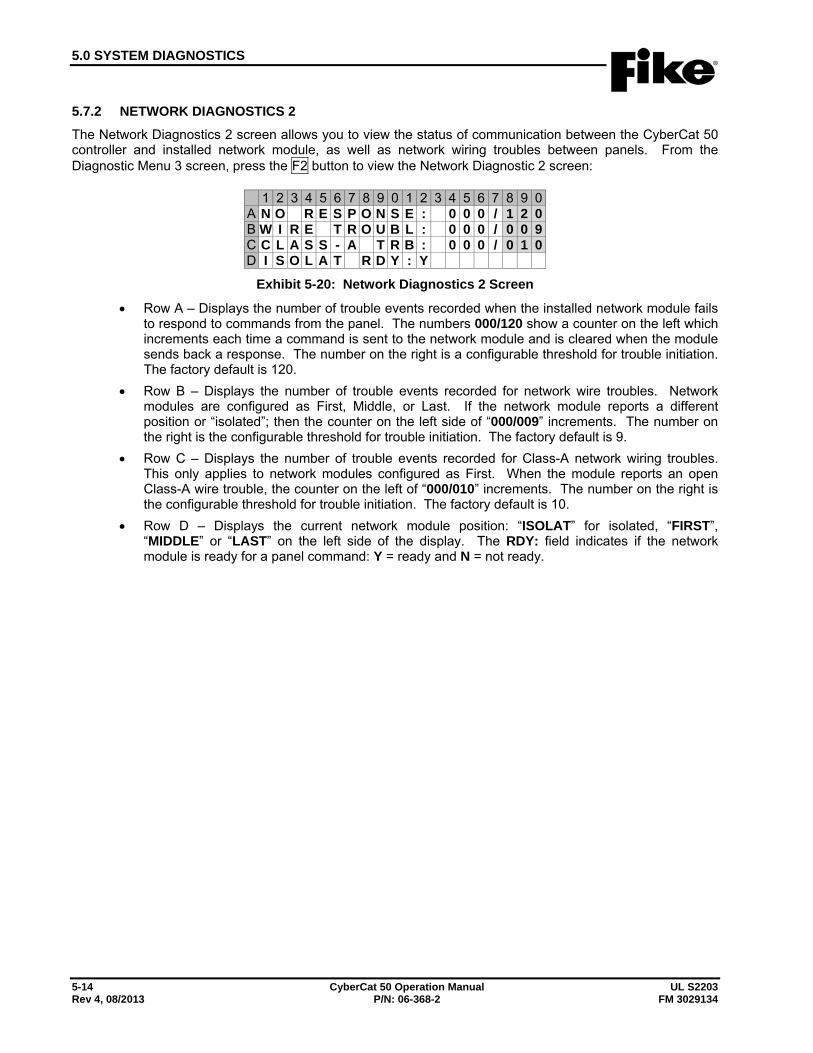
5.0 SYSTEM DIAGNOSTICS
5-14 CyberCat 50 Operation Manual UL S2203 Rev 4, 08/2013 P/N: 06-368-2 FM 3029134
5.7.2 NETWORK DIAGNOSTICS 2 The Network Diagnostics 2 screen allows you to view the status of communication between the CyberCat 50 controller and installed network module, as well as network wiring troubles between panels. From the Diagnostic Menu 3 screen, press the F2 button to view the Network Diagnostic 2 screen:
1 2 3 4 5 6 7 8 9 0 1 2 3 4 5 6 7 8 9 0A N O R E S P O N S E : 0 0 0 / 1 2 0B W I R E T R O U B L : 0 0 0 / 0 0 9C C L A S S - A T R B : 0 0 0 / 0 1 0D I S O L A T R D Y : Y
Exhibit 5-20: Network Diagnostics 2 Screen
• Row A – Displays the number of trouble events recorded when the installed network module fails to respond to commands from the panel. The numbers 000/120 show a counter on the left which increments each time a command is sent to the network module and is cleared when the module sends back a response. The number on the right is a configurable threshold for trouble initiation. The factory default is 120.
• Row B – Displays the number of trouble events recorded for network wire troubles. Network modules are configured as First, Middle, or Last. If the network module reports a different position or “isolated”; then the counter on the left side of “000/009” increments. The number on the right is the configurable threshold for trouble initiation. The factory default is 9.
• Row C – Displays the number of trouble events recorded for Class-A network wiring troubles. This only applies to network modules configured as First. When the module reports an open Class-A wire trouble, the counter on the left of “000/010” increments. The number on the right is the configurable threshold for trouble initiation. The factory default is 10.
• Row D – Displays the current network module position: “ISOLAT” for isolated, “FIRST”, “MIDDLE” or “LAST” on the left side of the display. The RDY: field indicates if the network module is ready for a panel command: Y = ready and N = not ready.
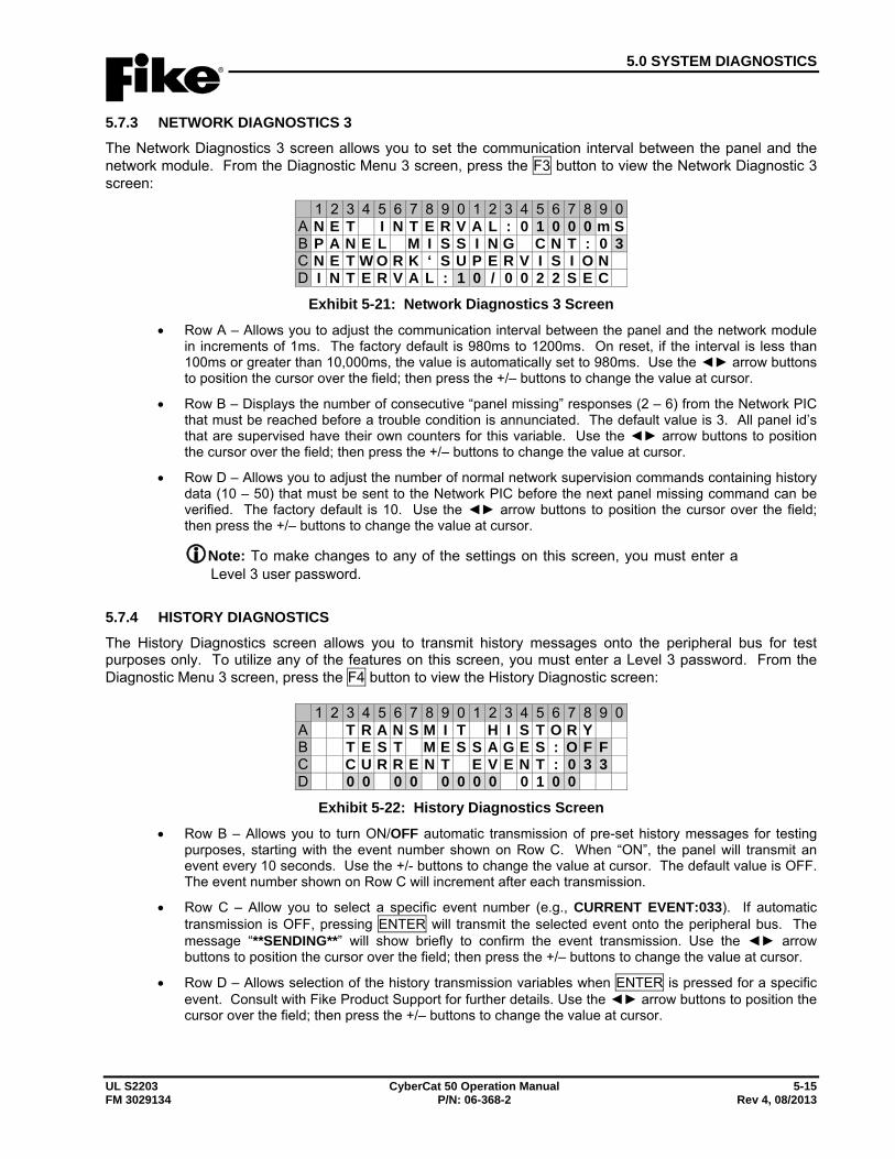
5.0 SYSTEM DIAGNOSTICS
UL S2203 CyberCat 50 Operation Manual 5-15 FM 3029134 P/N: 06-368-2 Rev 4, 08/2013
5.7.3 NETWORK DIAGNOSTICS 3 The Network Diagnostics 3 screen allows you to set the communication interval between the panel and the network module. From the Diagnostic Menu 3 screen, press the F3 button to view the Network Diagnostic 3 screen:
1 2 3 4 5 6 7 8 9 0 1 2 3 4 5 6 7 8 9 0A N E T I N T E R V A L : 0 1 0 0 0 m SB P A N E L M I S S I N G C N T : 0 3C N E T W O R K ‘ S U P E R V I S I O ND I N T E R V A L : 1 0 / 0 0 2 2 S E C
Exhibit 5-21: Network Diagnostics 3 Screen
• Row A – Allows you to adjust the communication interval between the panel and the network module in increments of 1ms. The factory default is 980ms to 1200ms. On reset, if the interval is less than 100ms or greater than 10,000ms, the value is automatically set to 980ms. Use the ◄► arrow buttons to position the cursor over the field; then press the +/– buttons to change the value at cursor.
• Row B – Displays the number of consecutive “panel missing” responses (2 – 6) from the Network PIC that must be reached before a trouble condition is annunciated. The default value is 3. All panel id’s that are supervised have their own counters for this variable. Use the ◄► arrow buttons to position the cursor over the field; then press the +/– buttons to change the value at cursor.
• Row D – Allows you to adjust the number of normal network supervision commands containing history data (10 – 50) that must be sent to the Network PIC before the next panel missing command can be verified. The factory default is 10. Use the ◄► arrow buttons to position the cursor over the field; then press the +/– buttons to change the value at cursor.
Note: To make changes to any of the settings on this screen, you must enter a Level 3 user password.
5.7.4 HISTORY DIAGNOSTICS The History Diagnostics screen allows you to transmit history messages onto the peripheral bus for test purposes only. To utilize any of the features on this screen, you must enter a Level 3 password. From the Diagnostic Menu 3 screen, press the F4 button to view the History Diagnostic screen:
1 2 3 4 5 6 7 8 9 0 1 2 3 4 5 6 7 8 9 0A T R A N S M I T H I S T O R YB T E S T M E S S A G E S : O F FC C U R R E N T E V E N T : 0 3 3D 0 0 0 0 0 0 0 0 0 1 0 0
Exhibit 5-22: History Diagnostics Screen
• Row B – Allows you to turn ON/OFF automatic transmission of pre-set history messages for testing purposes, starting with the event number shown on Row C. When “ON”, the panel will transmit an event every 10 seconds. Use the +/- buttons to change the value at cursor. The default value is OFF. The event number shown on Row C will increment after each transmission.
• Row C – Allow you to select a specific event number (e.g., CURRENT EVENT:033). If automatic transmission is OFF, pressing ENTER will transmit the selected event onto the peripheral bus. The message “**SENDING**” will show briefly to confirm the event transmission. Use the ◄► arrow buttons to position the cursor over the field; then press the +/– buttons to change the value at cursor.
• Row D – Allows selection of the history transmission variables when ENTER is pressed for a specific event. Consult with Fike Product Support for further details. Use the ◄► arrow buttons to position the cursor over the field; then press the +/– buttons to change the value at cursor.
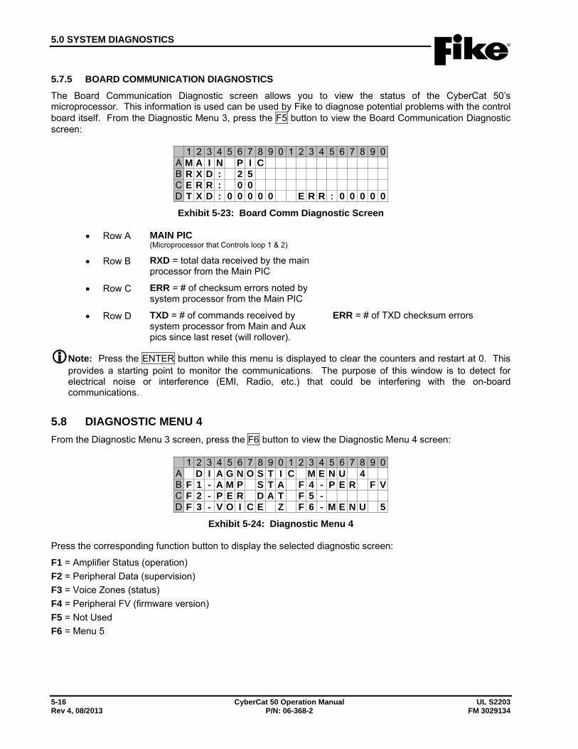
5.0 SYSTEM DIAGNOSTICS
5-16 CyberCat 50 Operation Manual UL S2203 Rev 4, 08/2013 P/N: 06-368-2 FM 3029134
5.7.5 BOARD COMMUNICATION DIAGNOSTICS The Board Communication Diagnostic screen allows you to view the status of the CyberCat 50’s microprocessor. This information is used can be used by Fike to diagnose potential problems with the control board itself. From the Diagnostic Menu 3, press the F5 button to view the Board Communication Diagnostic screen:
1 2 3 4 5 6 7 8 9 0 1 2 3 4 5 6 7 8 9 0A M A I N P I CB R X D : 2 5C E R R : 0 0D T X D : 0 0 0 0 0 E R R : 0 0 0 0 0
Exhibit 5-23: Board Comm Diagnostic Screen
• Row A MAIN PIC (Microprocessor that Controls loop 1 & 2)
• Row B RXD = total data received by the main processor from the Main PIC
• Row C ERR = # of checksum errors noted by system processor from the Main PIC
• Row D TXD = # of commands received by system processor from Main and Aux pics since last reset (will rollover).
ERR = # of TXD checksum errors
Note: Press the ENTER button while this menu is displayed to clear the counters and restart at 0. This provides a starting point to monitor the communications. The purpose of this window is to detect for electrical noise or interference (EMI, Radio, etc.) that could be interfering with the on-board communications.
5.8 DIAGNOSTIC MENU 4 From the Diagnostic Menu 3 screen, press the F6 button to view the Diagnostic Menu 4 screen:
1 2 3 4 5 6 7 8 9 0 1 2 3 4 5 6 7 8 9 0A D I A G N O S T I C M E N U 4B F 1 - A M P S T A F 4 - P E R F VC F 2 - P E R D A T F 5 -D F 3 - V O I C E Z F 6 - M E N U 5
Exhibit 5-24: Diagnostic Menu 4
Press the corresponding function button to display the selected diagnostic screen:
F1 = Amplifier Status (operation) F2 = Peripheral Data (supervision) F3 = Voice Zones (status) F4 = Peripheral FV (firmware version) F5 = Not Used F6 = Menu 5
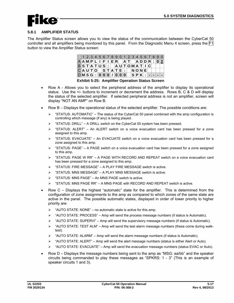
5.0 SYSTEM DIAGNOSTICS
UL S2203 CyberCat 50 Operation Manual 5-17 FM 3029134 P/N: 06-368-2 Rev 4, 08/2013
5.8.1 AMPLIFIER STATUS The Amplifier Status screen allows you to view the status of the communication between the CyberCat 50 controller and all amplifiers being monitored by this panel. From the Diagnostic Menu 4 screen, press the F1 button to view the Amplifier Status screen:
1 2 3 4 5 6 7 8 9 0 1 2 3 4 5 6 7 8 9 0A A M P L I F I E R A T A D D R : 0 2B S T A T U S : A U T O M A T I CC A U T O S T A T E : N O N ED M S G : 0 0 0 / 0 0 0 S P K : - - - -Exhibit 5-25: Amplifier Operation Status Screen
• Row A - Allows you to select the peripheral address of the amplifier to display its operational status. Use the +/- buttons to increment or decrement the address. Rows B, C & D will display the status of the selected amplifier. If selected peripheral address is not an amplifier, screen will display “NOT AN AMP” on Row B.
• Row B – Displays the operational status of the selected amplifier. The possible conditions are: “STATUS: AUTOMATIC” – The status of the CyberCat 50 panel combined with the amp configuration is
controlling which message (if any) is being played. “STATUS: DRILL” – A DRILL switch on the CyberCat 50 system has been pressed. “STATUS: ALERT” – An ALERT switch on a voice evacuation card has been pressed for a zone
assigned to this amp. “STATUS: EVACUATE” – An EVACUATE switch on a voice evacuation card has been pressed for a
zone assigned to this amp. “STATUS: PAGE” – A PAGE switch on a voice evacuation card has been pressed for a zone assigned
to this amp. “STATUS: PAGE W RR” – A PAGE WITH RECORD AND REPEAT switch on a voice evacuation card
has been pressed for a zone assigned to this amp. “STATUS: FIRE MESSAGE” – A PLAY FIRE MESSAGE switch is active. “STATUS: MNS MESSAGE” – A PLAY MNS MESSAGE switch is active. “STATUS: MNS PAGE” – An MNS PAGE switch is active. “STATUS: MNS PAGE RR” – A MNS PAGE with RECORD AND REPEAT switch is active.
• Row C – Displays the highest “automatic” state for the amplifier. This is determined from the configuration of zone assignments to the amp as compared to which zones of the same state are active in the panel. The possible automatic states, displayed in order of lower priority to higher priority are:
“AUTO STATE: NONE” – no automatic state is active for this amp. “AUTO STATE: PROCESS” – Amp will send the process message numbers (if status is Automatic). “AUTO STATE: SUPERVI” – Amp will send the supervisory message numbers (if status is Automatic). “AUTO STATE: TEST ALM” – Amp will send the test alarm message numbers (these come during walk-
test). “AUTO STATE: ALARM” – Amp will send the alarm message numbers (if status is Automatic). “AUTO STATE: ALERT” – Amp will send the alert message numbers (status is either Alert or Auto). “AUTO STATE: EVACUATE” – Amp will send the evacuation message numbers (status EVAC or Auto).
• Row D – Displays the message numbers being sent to the amp as “MSG: aa/bb” and the speaker circuits being commanded to play these messages as “SPKRS: 1 - 3” (This is an example of speaker circuits 1 and 3).
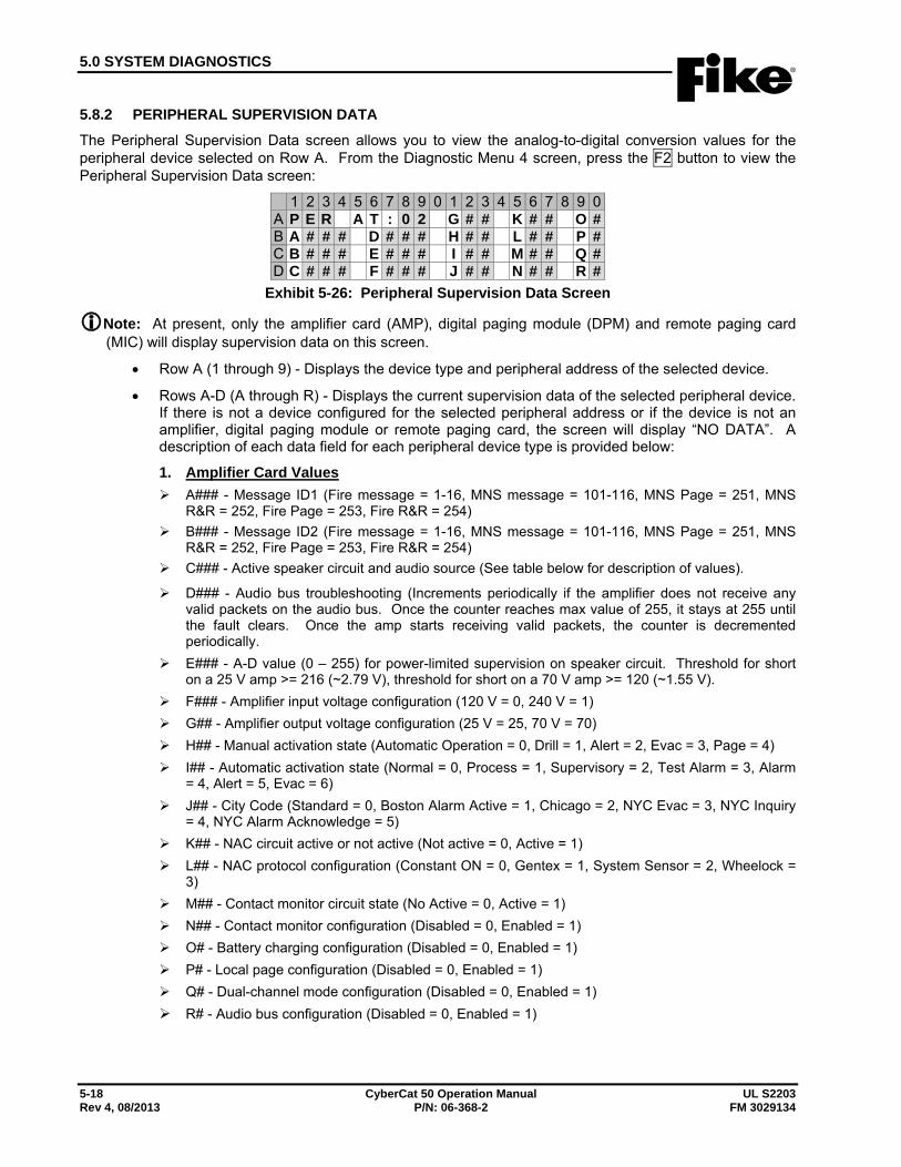
5.0 SYSTEM DIAGNOSTICS
5-18 CyberCat 50 Operation Manual UL S2203 Rev 4, 08/2013 P/N: 06-368-2 FM 3029134
5.8.2 PERIPHERAL SUPERVISION DATA The Peripheral Supervision Data screen allows you to view the analog-to-digital conversion values for the peripheral device selected on Row A. From the Diagnostic Menu 4 screen, press the F2 button to view the Peripheral Supervision Data screen:
1 2 3 4 5 6 7 8 9 0 1 2 3 4 5 6 7 8 9 0A P E R A T : 0 2 G # # K # # O #B A # # # D # # # H # # L # # P #C B # # # E # # # I # # M # # Q #D C # # # F # # # J # # N # # R #
Exhibit 5-26: Peripheral Supervision Data Screen
Note: At present, only the amplifier card (AMP), digital paging module (DPM) and remote paging card (MIC) will display supervision data on this screen.
• Row A (1 through 9) - Displays the device type and peripheral address of the selected device.
• Rows A-D (A through R) - Displays the current supervision data of the selected peripheral device. If there is not a device configured for the selected peripheral address or if the device is not an amplifier, digital paging module or remote paging card, the screen will display “NO DATA”. A description of each data field for each peripheral device type is provided below:
1. Amplifier Card Values A### - Message ID1 (Fire message = 1-16, MNS message = 101-116, MNS Page = 251, MNS
R&R = 252, Fire Page = 253, Fire R&R = 254) B### - Message ID2 (Fire message = 1-16, MNS message = 101-116, MNS Page = 251, MNS
R&R = 252, Fire Page = 253, Fire R&R = 254) C### - Active speaker circuit and audio source (See table below for description of values).
D### - Audio bus troubleshooting (Increments periodically if the amplifier does not receive any valid packets on the audio bus. Once the counter reaches max value of 255, it stays at 255 until the fault clears. Once the amp starts receiving valid packets, the counter is decremented periodically.
E### - A-D value (0 – 255) for power-limited supervision on speaker circuit. Threshold for short on a 25 V amp >= 216 (~2.79 V), threshold for short on a 70 V amp >= 120 (~1.55 V).
F### - Amplifier input voltage configuration (120 V = 0, 240 V = 1) G## - Amplifier output voltage configuration (25 V = 25, 70 V = 70) H## - Manual activation state (Automatic Operation = 0, Drill = 1, Alert = 2, Evac = 3, Page = 4) I## - Automatic activation state (Normal = 0, Process = 1, Supervisory = 2, Test Alarm = 3, Alarm
= 4, Alert = 5, Evac = 6) J## - City Code (Standard = 0, Boston Alarm Active = 1, Chicago = 2, NYC Evac = 3, NYC Inquiry
= 4, NYC Alarm Acknowledge = 5) K## - NAC circuit active or not active (Not active = 0, Active = 1) L## - NAC protocol configuration (Constant ON = 0, Gentex = 1, System Sensor = 2, Wheelock =
3) M## - Contact monitor circuit state (No Active = 0, Active = 1) N## - Contact monitor configuration (Disabled = 0, Enabled = 1) O# - Battery charging configuration (Disabled = 0, Enabled = 1) P# - Local page configuration (Disabled = 0, Enabled = 1) Q# - Dual-channel mode configuration (Disabled = 0, Enabled = 1) R# - Audio bus configuration (Disabled = 0, Enabled = 1)
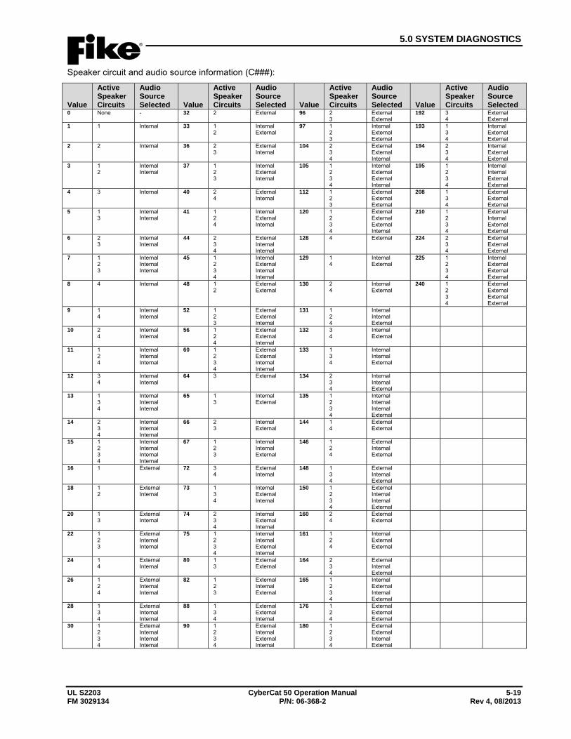
5.0 SYSTEM DIAGNOSTICS
UL S2203 CyberCat 50 Operation Manual 5-19 FM 3029134 P/N: 06-368-2 Rev 4, 08/2013
Speaker circuit and audio source information (C###):
Value
Active Speaker Circuits
Audio Source Selected Value
Active Speaker Circuits
Audio Source Selected Value
Active Speaker Circuits
Audio Source Selected Value
Active Speaker Circuits
Audio Source Selected
0 None - 32 2 External 96 2 3
External External
192 3 4
External External
1 1 Internal 33 1 2
Internal External
97 1 2 3
Internal External External
193 1 3 4
Internal External External
2 2 Internal 36 2 3
External Internal
104 2 3 4
External External Internal
194 2 3 4
Internal External External
3 1 2
Internal Internal
37 1 2 3
Internal External Internal
105 1 2 3 4
Internal External External Internal
195 1 2 3 4
Internal Internal External External
4 3 Internal 40 2 4
External Internal
112 1 2 3
External External External
208 1 3 4
External External External
5 1 3
Internal Internal
41 1 2 4
Internal External Internal
120 1 2 3 4
External External External Internal
210 1 2 3 4
External Internal External External
6 2 3
Internal Internal
44 2 3 4
External Internal Internal
128 4 External 224 2 3 4
External External External
7 1 2 3
Internal Internal Internal
45 1 2 3 4
Internal External Internal Internal
129 1 4
Internal External
225 1 2 3 4
Internal External External External
8 4 Internal 48 1 2
External External
130 2 4
Internal External
240 1 2 3 4
External External External External
9 1 4
Internal Internal
52 1 2 3
External External Internal
131 1 2 4
Internal Internal External
10 2 4
Internal Internal
56 1 2 4
External External Internal
132 3 4
Internal External
11 1 2 4
Internal Internal Internal
60 1 2 3 4
External External Internal Internal
133 1 3 4
Internal Internal External
12 3 4
Internal Internal
64 3 External 134 2 3 4
Internal Internal External
13 1 3 4
Internal Internal Internal
65 1 3
Internal External
135 1 2 3 4
Internal Internal Internal External
14 2 3 4
Internal Internal Internal
66 2 3
Internal External
144 1 4
External External
15 1 2 3 4
Internal Internal Internal Internal
67 1 2 3
Internal Internal External
146 1 2 4
External Internal External
16 1 External 72 3 4
External Internal
148 1 3 4
External Internal External
18 1 2
External Internal
73 1 3 4
Internal External Internal
150 1 2 3 4
External Internal Internal External
20 1 3
External Internal
74 2 3 4
Internal External Internal
160 2 4
External External
22 1 2 3
External Internal Internal
75 1 2 3 4
Internal Internal External Internal
161 1 2 4
Internal External External
24 1 4
External Internal
80 1 3
External External
164 2 3 4
External Internal External
26 1 2 4
External Internal Internal
82 1 2 3
External Internal External
165 1 2 3 4
Internal External Internal External
28 1 3 4
External Internal Internal
88 1 3 4
External External Internal
176 1 2 4
External External External
30 1 2 3 4
External Internal Internal Internal
90 1 2 3 4
External Internal External Internal
180 1 2 3 4
External External Internal External
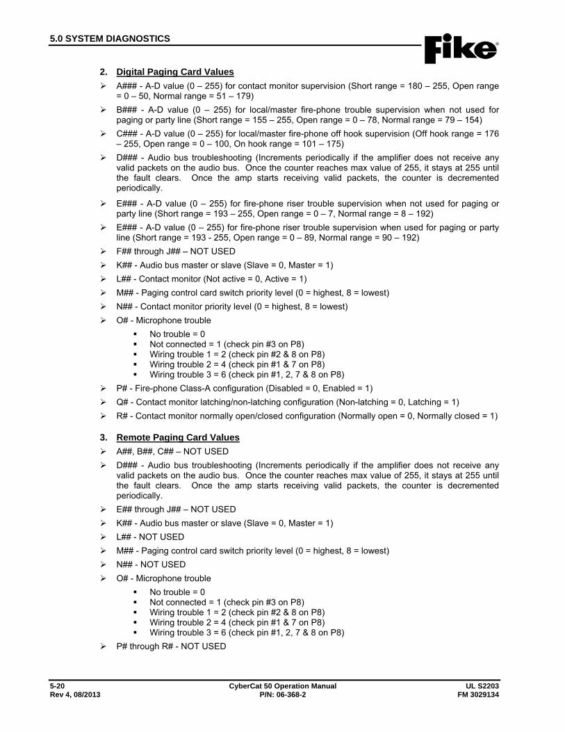
5.0 SYSTEM DIAGNOSTICS
5-20 CyberCat 50 Operation Manual UL S2203 Rev 4, 08/2013 P/N: 06-368-2 FM 3029134
2. Digital Paging Card Values A### - A-D value (0 – 255) for contact monitor supervision (Short range = 180 – 255, Open range
= 0 – 50, Normal range = 51 – 179) B### - A-D value (0 – 255) for local/master fire-phone trouble supervision when not used for
paging or party line (Short range = 155 – 255, Open range = 0 – 78, Normal range = 79 – 154) C### - A-D value (0 – 255) for local/master fire-phone off hook supervision (Off hook range = 176
– 255, Open range = 0 – 100, On hook range = 101 – 175) D### - Audio bus troubleshooting (Increments periodically if the amplifier does not receive any
valid packets on the audio bus. Once the counter reaches max value of 255, it stays at 255 until the fault clears. Once the amp starts receiving valid packets, the counter is decremented periodically.
E### - A-D value (0 – 255) for fire-phone riser trouble supervision when not used for paging or party line (Short range = 193 – 255, Open range = 0 – 7, Normal range = 8 – 192)
E### - A-D value (0 – 255) for fire-phone riser trouble supervision when used for paging or party line (Short range = 193 - 255, Open range = 0 – 89, Normal range = 90 – 192)
F## through J## – NOT USED K## - Audio bus master or slave (Slave = 0, Master = 1) L## - Contact monitor (Not active = 0, Active = 1) M## - Paging control card switch priority level (0 = highest, 8 = lowest) N## - Contact monitor priority level (0 = highest, 8 = lowest) O# - Microphone trouble
No trouble = 0 Not connected = 1 (check pin #3 on P8) Wiring trouble 1 = 2 (check pin #2 & 8 on P8) Wiring trouble 2 = 4 (check pin #1 & 7 on P8) Wiring trouble 3 = 6 (check pin #1, 2, 7 & 8 on P8)
P# - Fire-phone Class-A configuration (Disabled = 0, Enabled = 1) Q# - Contact monitor latching/non-latching configuration (Non-latching = 0, Latching = 1) R# - Contact monitor normally open/closed configuration (Normally open = 0, Normally closed = 1)
3. Remote Paging Card Values A##, B##, C## – NOT USED D### - Audio bus troubleshooting (Increments periodically if the amplifier does not receive any
valid packets on the audio bus. Once the counter reaches max value of 255, it stays at 255 until the fault clears. Once the amp starts receiving valid packets, the counter is decremented periodically.
E## through J## – NOT USED K## - Audio bus master or slave (Slave = 0, Master = 1) L## - NOT USED M## - Paging control card switch priority level (0 = highest, 8 = lowest) N## - NOT USED O# - Microphone trouble
No trouble = 0 Not connected = 1 (check pin #3 on P8) Wiring trouble 1 = 2 (check pin #2 & 8 on P8) Wiring trouble 2 = 4 (check pin #1 & 7 on P8) Wiring trouble 3 = 6 (check pin #1, 2, 7 & 8 on P8)
P# through R# - NOT USED
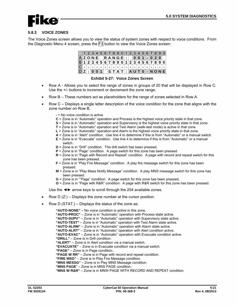
5.0 SYSTEM DIAGNOSTICS
UL S2203 CyberCat 50 Operation Manual 5-21 FM 3029134 P/N: 06-368-2 Rev 4, 08/2013
5.8.3 VOICE ZONES The Voice Zones screen allows you to view the status of system zones with respect to voice conditions. From the Diagnostic Menu 4 screen, press the F3 button to view the Voice Zones screen:
1 2 3 4 5 6 7 8 9 0 1 2 3 4 5 6 7 8 9 0A Z O N E R A N G E : 0 0 1 - 0 2 0B 1 2 3 4 5 6 7 8 9 0 1 2 3 4 5 6 7 8 9 0C - - - - - - - - - - - - - - - - - - - -D Z : 0 0 1 S T A T : A U T 0 - N O N E
Exhibit 5-27: Voice Zones Screen
• Row A - Allows you to select the range of zones in groups of 20 that will be displayed in Row C. Use the +/- buttons to increment or decrement the zone range.
• Row B – These numbers act as placeholders for the range of zones selected in Row A.
• Row C – Displays a single letter description of the voice condition for the zone that aligns with the zone number on Row B.
- = No voice condition is active C = Zone is in “Automatic” operation and Process is the highest voice priority state in that zone. S = Zone is in “Automatic” operation and Supervisory is the highest voice priority state in that zone. T = Zone is in “Automatic” operation and Test Alarm (walk-test mode) is active in that zone. L = Zone is in “Automatic” operation and Alarm is the highest voice priority state in that zone. A = Zone is in “Alert” condition. Use line 4 to determine if this is from “Automatic” or a manual switch. E = Zone is in “Evacuate” condition. Use line 4 to determine if this is from “Automatic” or a manual
switch. D = Zone is in “Drill” condition. The drill switch has been pressed. P = Zone is in “Page” condition. A page switch for this zone has been pressed. R = Zone is in “Page with Record and Repeat” condition. A page with record and repeat switch for this
zone has been pressed. F = Zone is in “Play Fire Message” condition. A play fire message switch for this zone has been
pressed. M = Zone is in “Play Mass Notify Message” condition. A play MNS message switch for this zone has
been pressed. G = Zone is in “”Page” condition. A page switch for this zone has been pressed. O = Zone is in “Page with R&R” condition. A page with R&R switch for this zone has been pressed.
Use the ◄► arrow keys to scroll through the 254 available zones.
• Row D (Z:) – Displays the zone number at the cursor position.
• Row D (STAT:) – Displays the status of the zone as: “AUTO-NONE” – No voice condition is active in this zone. “AUTO-PROC” – Zone is in “Automatic” operation with Process state active. “AUTO-SUPV” – Zone is in “Automatic” operation with Supervisory state active. “AUTO-TEST” – Zone is in “Automatic” operation with Test Alarm state active. “AUTO-ALRM” – Zone is in “Automatic” operation with Alarm state active. “AUTO-ALRT” – Zone is in “Automatic” operation with Alert condition active. “AUTO-EVAC” – Zone is in “Automatic” operation with Evacuate condition active. “DRILL” – Zone is in Drill condition. “ALERT” – Zone is in Alert condition via a manual switch. “EVACUATE” – Zone is in Evacuate condition via a manual switch. “PAGE” – Zone is in Page condition. “PAGE W RR” – Zone is in Page with record and repeat condition. “FIRE MSG” – Zone is in Play Fire Message condition. “MNS MESSG” – Zone is in Play MNS Message condition. “MNS PAGE” – Zone is in MNS PAGE condition. “MNS W R&R” – Zone is in MNW PAGE WITH RECORD AND REPEAT condition.
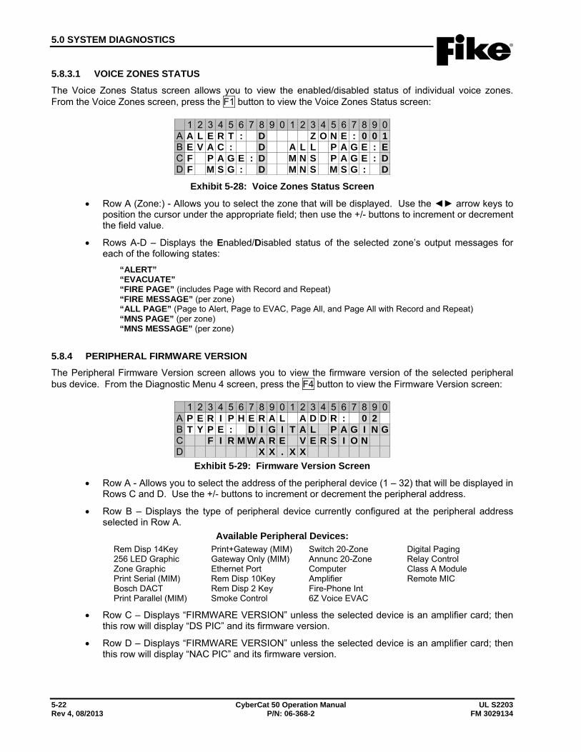
5.0 SYSTEM DIAGNOSTICS
5-22 CyberCat 50 Operation Manual UL S2203 Rev 4, 08/2013 P/N: 06-368-2 FM 3029134
5.8.3.1 VOICE ZONES STATUS The Voice Zones Status screen allows you to view the enabled/disabled status of individual voice zones. From the Voice Zones screen, press the F1 button to view the Voice Zones Status screen:
1 2 3 4 5 6 7 8 9 0 1 2 3 4 5 6 7 8 9 0A A L E R T : D Z O N E : 0 0 1B E V A C : D A L L P A G E : EC F P A G E : D M N S P A G E : DD F M S G : D M N S M S G : D
Exhibit 5-28: Voice Zones Status Screen
• Row A (Zone:) - Allows you to select the zone that will be displayed. Use the ◄► arrow keys to position the cursor under the appropriate field; then use the +/- buttons to increment or decrement the field value.
• Rows A-D – Displays the Enabled/Disabled status of the selected zone’s output messages for each of the following states:
“ALERT” “EVACUATE” “FIRE PAGE” (includes Page with Record and Repeat) “FIRE MESSAGE” (per zone) “ALL PAGE” (Page to Alert, Page to EVAC, Page All, and Page All with Record and Repeat) “MNS PAGE” (per zone) “MNS MESSAGE” (per zone)
5.8.4 PERIPHERAL FIRMWARE VERSION The Peripheral Firmware Version screen allows you to view the firmware version of the selected peripheral bus device. From the Diagnostic Menu 4 screen, press the F4 button to view the Firmware Version screen:
1 2 3 4 5 6 7 8 9 0 1 2 3 4 5 6 7 8 9 0A P E R I P H E R A L A D D R : 0 2B T Y P E : D I G I T A L P A G I N GC F I R M W A R E V E R S I O ND X X . X X
Exhibit 5-29: Firmware Version Screen
• Row A - Allows you to select the address of the peripheral device (1 – 32) that will be displayed in Rows C and D. Use the +/- buttons to increment or decrement the peripheral address.
• Row B – Displays the type of peripheral device currently configured at the peripheral address selected in Row A.
Available Peripheral Devices: Rem Disp 14Key Print+Gateway (MIM) Switch 20-Zone Digital Paging 256 LED Graphic Gateway Only (MIM) Annunc 20-Zone Relay Control Zone Graphic Ethernet Port Computer Class A Module Print Serial (MIM) Rem Disp 10Key Amplifier Remote MIC Bosch DACT Rem Disp 2 Key Fire-Phone Int Print Parallel (MIM) Smoke Control 6Z Voice EVAC
• Row C – Displays “FIRMWARE VERSION” unless the selected device is an amplifier card; then this row will display “DS PIC” and its firmware version.
• Row D – Displays “FIRMWARE VERSION” unless the selected device is an amplifier card; then this row will display “NAC PIC” and its firmware version.

5.0 SYSTEM DIAGNOSTICS
UL S2203 CyberCat 50 Operation Manual 5-23 FM 3029134 P/N: 06-368-2 Rev 4, 08/2013
5.9 DIAGNOSTIC MENU 5 From the Diagnostic Menu 4 screen, press the F6 button to view the Diagnostic Menu 5 screen:
1 2 3 4 5 6 7 8 9 0 1 2 3 4 5 6 7 8 9 0A D I A G N O S T I C M E N U 5B F 1 - P A G E S F 4 - F A S S TC F 2 - A U D P R I F 5 -D F 3 - M S G I D F 6 - M E N U 1
Exhibit 5-30: Diagnostic Menu 5
Press the corresponding function button to display the selected diagnostic screen:
F1 = Page Status F2 = Audio Priority Status F3 = Play Message ID Status F4 = FAAST Detector Status F5 = Not Used F6 = Menu 1
5.9.1 PAGE STATUS The Page Status screen allows you to view the general “paging” status of the panel. There are no selectable items on this screen. From the Diagnostic Menu 5 screen, press the F1 button to view the Page Status screen:
1 2 3 4 5 6 7 8 9 0 1 2 3 4 5 6 7 8 9 0A A L E R T T O P A G E : O F FB E V A C T O P A G E : O F FC D
Exhibit 5-31: Page Status Screen
• Row A – When a Page-to-Alert switch is pressed and zones that were in Alert are now in page mode, this line shows “ALERT TO PAGE: ON”; otherwise, “ALERT TO PAGE: OFF” is displayed.
• Row B – When a Page-to-Evac switch is pressed and zones that were in EVAC are now in page mode, this line shows “EVAC TO PAGE: ON”; otherwise, “EVAC TO PAGE: OFF” is displayed.
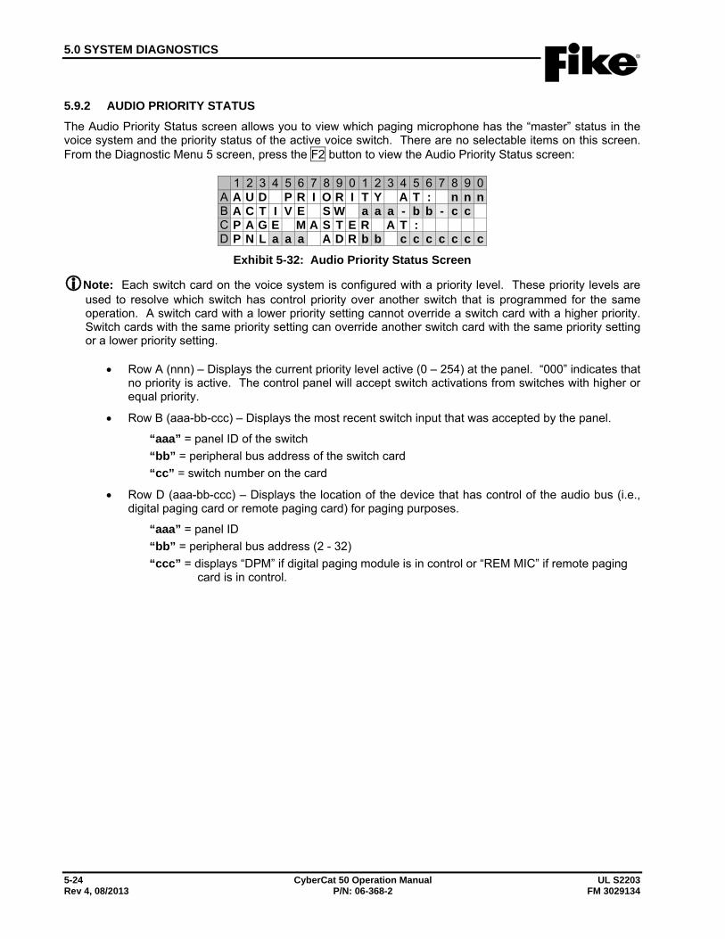
5.0 SYSTEM DIAGNOSTICS
5-24 CyberCat 50 Operation Manual UL S2203 Rev 4, 08/2013 P/N: 06-368-2 FM 3029134
5.9.2 AUDIO PRIORITY STATUS The Audio Priority Status screen allows you to view which paging microphone has the “master” status in the voice system and the priority status of the active voice switch. There are no selectable items on this screen. From the Diagnostic Menu 5 screen, press the F2 button to view the Audio Priority Status screen:
1 2 3 4 5 6 7 8 9 0 1 2 3 4 5 6 7 8 9 0A A U D P R I O R I T Y A T : n n nB A C T I V E S W a a a - b b - c cC P A G E M A S T E R A T :D P N L a a a A D R b b c c c c c c c
Exhibit 5-32: Audio Priority Status Screen
Note: Each switch card on the voice system is configured with a priority level. These priority levels are used to resolve which switch has control priority over another switch that is programmed for the same operation. A switch card with a lower priority setting cannot override a switch card with a higher priority. Switch cards with the same priority setting can override another switch card with the same priority setting or a lower priority setting.
• Row A (nnn) – Displays the current priority level active (0 – 254) at the panel. “000” indicates that no priority is active. The control panel will accept switch activations from switches with higher or equal priority.
• Row B (aaa-bb-ccc) – Displays the most recent switch input that was accepted by the panel.
“aaa” = panel ID of the switch “bb” = peripheral bus address of the switch card “cc” = switch number on the card
• Row D (aaa-bb-ccc) – Displays the location of the device that has control of the audio bus (i.e., digital paging card or remote paging card) for paging purposes.
“aaa” = panel ID “bb” = peripheral bus address (2 - 32) “ccc” = displays “DPM” if digital paging module is in control or “REM MIC” if remote paging
card is in control.
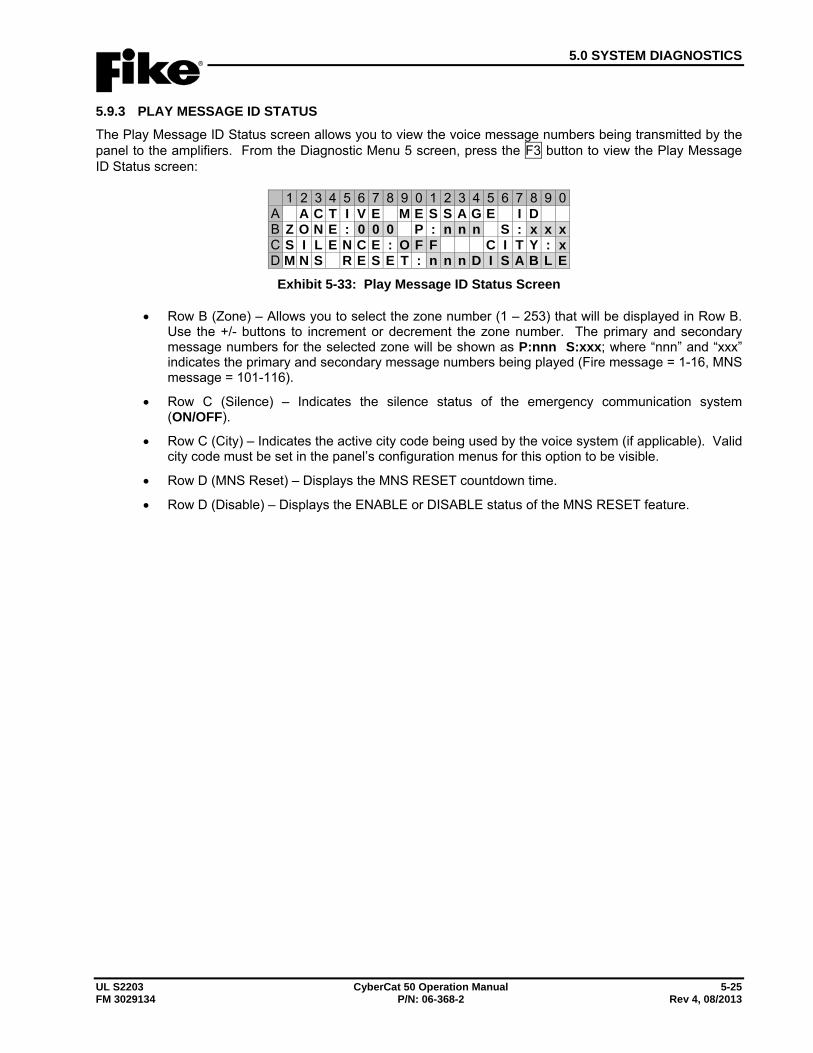
5.0 SYSTEM DIAGNOSTICS
UL S2203 CyberCat 50 Operation Manual 5-25 FM 3029134 P/N: 06-368-2 Rev 4, 08/2013
5.9.3 PLAY MESSAGE ID STATUS The Play Message ID Status screen allows you to view the voice message numbers being transmitted by the panel to the amplifiers. From the Diagnostic Menu 5 screen, press the F3 button to view the Play Message ID Status screen:
1 2 3 4 5 6 7 8 9 0 1 2 3 4 5 6 7 8 9 0A A C T I V E M E S S A G E I DB Z O N E : 0 0 0 P : n n n S : x x xC S I L E N C E : O F F C I T Y : xD M N S R E S E T : n n n D I S A B L E
Exhibit 5-33: Play Message ID Status Screen
• Row B (Zone) – Allows you to select the zone number (1 – 253) that will be displayed in Row B. Use the +/- buttons to increment or decrement the zone number. The primary and secondary message numbers for the selected zone will be shown as P:nnn S:xxx; where “nnn” and “xxx” indicates the primary and secondary message numbers being played (Fire message = 1-16, MNS message = 101-116).
• Row C (Silence) – Indicates the silence status of the emergency communication system (ON/OFF).
• Row C (City) – Indicates the active city code being used by the voice system (if applicable). Valid city code must be set in the panel’s configuration menus for this option to be visible.
• Row D (MNS Reset) – Displays the MNS RESET countdown time.
• Row D (Disable) – Displays the ENABLE or DISABLE status of the MNS RESET feature.
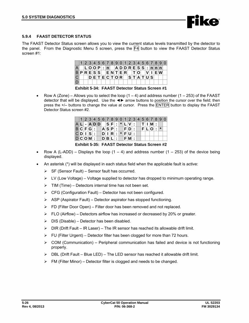
5.0 SYSTEM DIAGNOSTICS
5-26 CyberCat 50 Operation Manual UL S2203 Rev 4, 08/2013 P/N: 06-368-2 FM 3029134
5.9.4 FAAST DETECTOR STATUS The FAAST Detector Status screen allows you to view the current status levels transmitted by the detector to the panel. From the Diagnostic Menu 5 screen, press the F4 button to view the FAAST Detector Status screen #1:
1 2 3 4 5 6 7 8 9 0 1 2 3 4 5 6 7 8 9 0A L O O P : n A D D R E S S : n n nB P R E S S E N T E R T O V I E WC D E T E C T O R S T A T U SD Exhibit 5-34: FAAST Detector Status Screen #1
• Row A (Zone) – Allows you to select the loop (1 – 4) and address number (1 – 253) of the FAAST detector that will be displayed. Use the ◄► arrow buttons to position the cursor over the field; then press the +/– buttons to change the value at cursor. Press the ENTER button to display the FAAST Detector Status screen #2.
1 2 3 4 5 6 7 8 9 0 1 2 3 4 5 6 7 8 9 0A L - A D D S F : * L V : T I M :B C F G : A S P : F D : F L O : *C D I S : D I R : * F U :D C O M : D B L : F M :Exhibit 5-35: FAAST Detector Status Screen #2
• Row A (L-ADD) – Displays the loop (1 – 4) and address number (1 – 253) of the device being displayed.
• An asterisk (*) will be displayed in each status field when the applicable fault is active:
SF (Sensor Fault) – Sensor fault has occurred.
LV (Low Voltage) – Voltage supplied to detector has dropped to minimum operating range.
TIM (Time) – Detectors internal time has not been set.
CFG (Configuration Fault) – Detector has not been configured.
ASP (Aspirator Fault) – Detector aspirator has stopped functioning.
FD (Filter Door Open) – Filter door has been removed and not replaced.
FLO (Airflow) – Detectors airflow has increased or decreased by 20% or greater.
DIS (Disable) – Detector has been disabled.
DIR (Drift Fault – IR Laser) – The IR sensor has reached its allowable drift limit.
FU (Filter Urgent) – Detector filter has been clogged for more than 72 hours.
COM (Communication) – Peripheral communication has failed and device is not functioning properly.
DBL (Drift Fault – Blue LED) – The LED sensor has reached it allowable drift limit.
FM (Filter Minor) – Detector filter is clogged and needs to be changed.
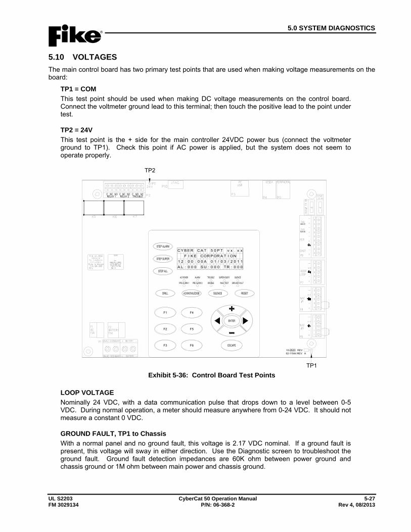
5.0 SYSTEM DIAGNOSTICS
UL S2203 CyberCat 50 Operation Manual 5-27 FM 3029134 P/N: 06-368-2 Rev 4, 08/2013
5.10 VOLTAGES The main control board has two primary test points that are used when making voltage measurements on the board:
TP1 = COM This test point should be used when making DC voltage measurements on the control board. Connect the voltmeter ground lead to this terminal; then touch the positive lead to the point under test.
TP2 = 24V This test point is the + side for the main controller 24VDC power bus (connect the voltmeter ground to TP1). Check this point if AC power is applied, but the system does not seem to operate properly.
10-2620 REV 02-11544 REV A
F1
F2
F3 F6
F5
F4
TACREBYC 5 0 P T v x . x xROCEKIF P OR A T I O N
A00:00:21 0 1 / 0 3 / 2 0 1 1:US000:LA 0 0 0 T R : 0 0 0
TP1
TP2
Exhibit 5-36: Control Board Test Points
LOOP VOLTAGE Nominally 24 VDC, with a data communication pulse that drops down to a level between 0-5 VDC. During normal operation, a meter should measure anywhere from 0-24 VDC. It should not measure a constant 0 VDC.
GROUND FAULT, TP1 to Chassis With a normal panel and no ground fault, this voltage is 2.17 VDC nominal. If a ground fault is present, this voltage will sway in either direction. Use the Diagnostic screen to troubleshoot the ground fault. Ground fault detection impedances are 60K ohm between power ground and chassis ground or 1M ohm between main power and chassis ground.
5.0 SYSTEM DIAGNOSTICS
5-28 CyberCat 50 Operation Manual UL S2203 Rev 4, 08/2013 P/N: 06-368-2 FM 3029134
Reserved for future use.
6.0 SYSTEM MAINTENANCE
UL S2203 CyberCat 50 Operation Manual 6-1 FM 3029134 P/N: 06-368-2 Rev 4, 08/2013
6.1 OVERVIEW To ensure operational integrity, the CyberCat 50 system should be properly tested and inspected at prescribed intervals as required by NFPA 72, National Fire Alarm code and the local Authority Having Jurisdiction (AHJ). The property or building owner is responsible for testing and maintaining the system. The owner can designate a representative (often the building manager) to be responsible for ensuring that the system is properly tested and maintained.
If the owner or designated representative does not choose to perform the testing and maintenance of the system or is not allowed to due to licensing laws or certification requirements, the owner shall contract with a qualified contractor to perform these services. Qualified personnel can include those persons that are:
A. Factory Trained and Certified
B. Certified by a nationally recognized certification organization acceptable to the authority having jurisdiction.
C. Registered, licensed, or certified by State or Local Authority
D. Trained, qualified and employed by an organization listed by a national testing laboratory
Records of all testing and maintenance shall be kept on the protected premises for a period of at least five (5) years. System defects and malfunctions shall be corrected. If a defect or malfunction is not corrected at the conclusion of system inspection, testing, or maintenance, the system owner or owner’s designated representative shall be informed of the impairment in writing.
6.2 ROUTINE MAINTENANCE Certain components of the CyberCat 50 require replacement at regular intervals, even though no obvious sign of failure is present.
Batteries (Lead Acid) - Replace every 3 years according to date of manufacture Battery (Lithium Coin cell) - Replace every 5 years with Fike battery P/N 02-4040 only. Use of another
battery may present a risk of fire or explosion.
The lithium battery is located on the back of the CyberCat 50 control board (bottom-center). To replace the lithium battery, use the following procedure:
1. Connect to the CyberCat 50 panel and download the system configuration before attempting to replace the lithium battery. Failure to do so will result in loss of system configuration.
2. Remove power from panel (AC and batteries) and wait 60 seconds before proceeding.
3. Remove the lithium battery by using thumb and forefinger to slide the coin cell from the battery holder on the system controller.
4. Insert new battery (P/N 02-4040) making sure to observe polarity marking on the battery holder.
5. Dispose of used battery promptly. Keep away from children. Do not disassemble and do not dispose of in fire.
6. Reapply power to the panel (AC and batteries).
7. Connect to the CyberCat 50 panel and upload the system configuration into the control board.
8. Verify proper operation of system.
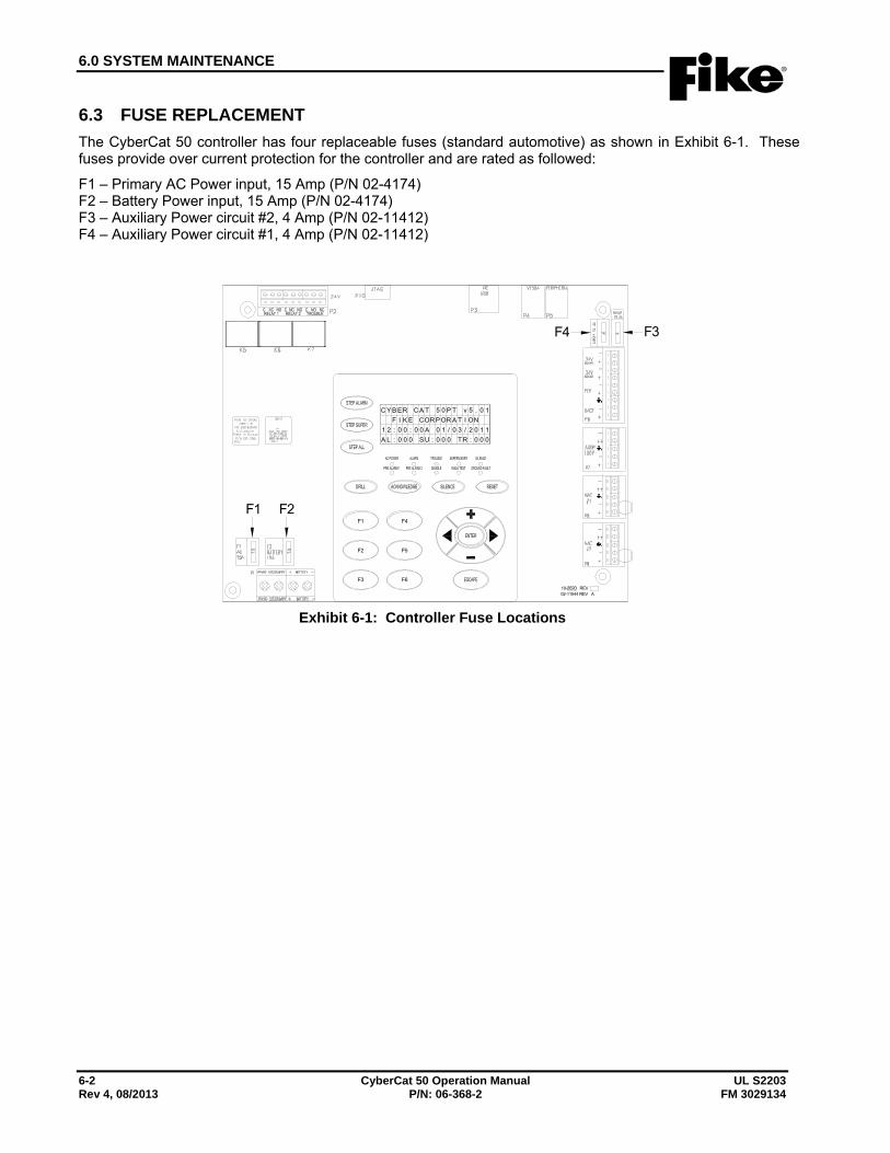
6.0 SYSTEM MAINTENANCE
6-2 CyberCat 50 Operation Manual UL S2203 Rev 4, 08/2013 P/N: 06-368-2 FM 3029134
6.3 FUSE REPLACEMENT The CyberCat 50 controller has four replaceable fuses (standard automotive) as shown in Exhibit 6-1. These fuses provide over current protection for the controller and are rated as followed:
F1 – Primary AC Power input, 15 Amp (P/N 02-4174) F2 – Battery Power input, 15 Amp (P/N 02-4174) F3 – Auxiliary Power circuit #2, 4 Amp (P/N 02-11412) F4 – Auxiliary Power circuit #1, 4 Amp (P/N 02-11412)
10-2620 REV 02-11544 REV A
F1
F2
F3 F6
F5
F4
TACREBYC 5 0 P T v 5 . 0 1ROCEKIF POR A T I ON
A00:00:21 0 1 / 0 3 / 2 0 1 1:US00
F1 F2
F4 F3
0:LA 0 0 0 T R : 0 0 0
Exhibit 6-1: Controller Fuse Locations
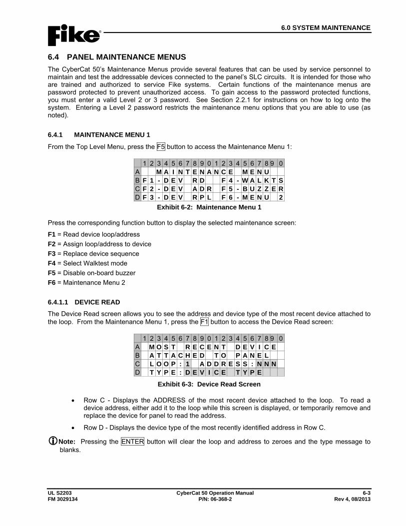
6.0 SYSTEM MAINTENANCE
UL S2203 CyberCat 50 Operation Manual 6-3 FM 3029134 P/N: 06-368-2 Rev 4, 08/2013
6.4 PANEL MAINTENANCE MENUS The CyberCat 50’s Maintenance Menus provide several features that can be used by service personnel to maintain and test the addressable devices connected to the panel’s SLC circuits. It is intended for those who are trained and authorized to service Fike systems. Certain functions of the maintenance menus are password protected to prevent unauthorized access. To gain access to the password protected functions, you must enter a valid Level 2 or 3 password. See Section 2.2.1 for instructions on how to log onto the system. Entering a Level 2 password restricts the maintenance menu options that you are able to use (as noted).
6.4.1 MAINTENANCE MENU 1
From the Top Level Menu, press the F5 button to access the Maintenance Menu 1:
1 2 3 4 5 6 7 8 9 0 1 2 3 4 5 6 7 8 9 0A M A I N T E N A N C E M E N UB F 1 - D E V R D F 4 - W A L K T SC F 2 - D E V A D R F 5 - B U Z Z E RD F 3 - D E V R P L F 6 - M E N U 2
Exhibit 6-2: Maintenance Menu 1
Press the corresponding function button to display the selected maintenance screen:
F1 = Read device loop/address F2 = Assign loop/address to device F3 = Replace device sequence F4 = Select Walktest mode F5 = Disable on-board buzzer F6 = Maintenance Menu 2
6.4.1.1 DEVICE READ The Device Read screen allows you to see the address and device type of the most recent device attached to the loop. From the Maintenance Menu 1, press the F1 button to access the Device Read screen:
1 2 3 4 5 6 7 8 9 0 1 2 3 4 5 6 7 8 9 0A M O S T R E C E N T D E V I C EB A T T A C H E D T O P A N E LC L O O P : 1 A D D R E S S : N N ND T Y P E : D E V I C E T Y P E
Exhibit 6-3: Device Read Screen
• Row C - Displays the ADDRESS of the most recent device attached to the loop. To read a device address, either add it to the loop while this screen is displayed, or temporarily remove and replace the device for panel to read the address.
• Row D - Displays the device type of the most recently identified address in Row C.
Note: Pressing the ENTER button will clear the loop and address to zeroes and the type message to blanks.
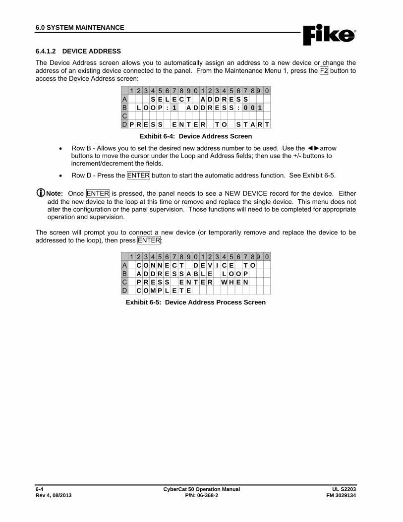
6.0 SYSTEM MAINTENANCE
6-4 CyberCat 50 Operation Manual UL S2203 Rev 4, 08/2013 P/N: 06-368-2 FM 3029134
6.4.1.2 DEVICE ADDRESS The Device Address screen allows you to automatically assign an address to a new device or change the address of an existing device connected to the panel. From the Maintenance Menu 1, press the F2 button to access the Device Address screen:
1 2 3 4 5 6 7 8 9 0 1 2 3 4 5 6 7 8 9 0A S E L E C T A D D R E S SB L O O P : 1 A D D R E S S : 0 0 1C D P R E S S E N T E R T O S T A R T
Exhibit 6-4: Device Address Screen
• Row B - Allows you to set the desired new address number to be used. Use the ◄►arrow buttons to move the cursor under the Loop and Address fields; then use the +/- buttons to increment/decrement the fields.
• Row D - Press the ENTER button to start the automatic address function. See Exhibit 6-5.
Note: Once ENTER is pressed, the panel needs to see a NEW DEVICE record for the device. Either add the new device to the loop at this time or remove and replace the single device. This menu does not alter the configuration or the panel supervision. Those functions will need to be completed for appropriate operation and supervision.
The screen will prompt you to connect a new device (or temporarily remove and replace the device to be addressed to the loop), then press ENTER:
1 2 3 4 5 6 7 8 9 0 1 2 3 4 5 6 7 8 9 0A C O N N E C T D E V I C E T OB A D D R E S S A B L E L O O PC P R E S S E N T E R W H E ND C O M P L E T E
Exhibit 6-5: Device Address Process Screen
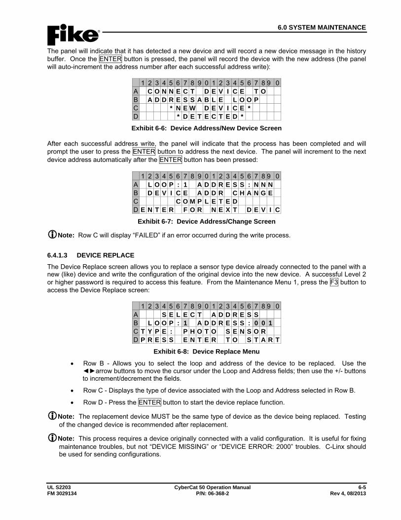
6.0 SYSTEM MAINTENANCE
UL S2203 CyberCat 50 Operation Manual 6-5 FM 3029134 P/N: 06-368-2 Rev 4, 08/2013
The panel will indicate that it has detected a new device and will record a new device message in the history buffer. Once the ENTER button is pressed, the panel will record the device with the new address (the panel will auto-increment the address number after each successful address write):
1 2 3 4 5 6 7 8 9 0 1 2 3 4 5 6 7 8 9 0A C O N N E C T D E V I C E T OB A D D R E S S A B L E L O O PC * N E W D E V I C E *D * D E T E C T E D *
Exhibit 6-6: Device Address/New Device Screen
After each successful address write, the panel will indicate that the process has been completed and will prompt the user to press the ENTER button to address the next device. The panel will increment to the next device address automatically after the ENTER button has been pressed:
1 2 3 4 5 6 7 8 9 0 1 2 3 4 5 6 7 8 9 0A L O O P : 1 A D D R E S S : N N NB D E V I C E A D D R C H A N G EC C O M P L E T E DD E N T E R F O R N E X T D E V I C
Exhibit 6-7: Device Address/Change Screen
Note: Row C will display “FAILED” if an error occurred during the write process.
6.4.1.3 DEVICE REPLACE The Device Replace screen allows you to replace a sensor type device already connected to the panel with a new (like) device and write the configuration of the original device into the new device. A successful Level 2 or higher password is required to access this feature. From the Maintenance Menu 1, press the F3 button to access the Device Replace screen:
1 2 3 4 5 6 7 8 9 0 1 2 3 4 5 6 7 8 9 0A S E L E C T A D D R E S SB L O O P : 1 A D D R E S S : 0 0 1C T Y P E : P H O T O S E N S O RD P R E S S E N T E R T O S T A R T
Exhibit 6-8: Device Replace Menu
• Row B - Allows you to select the loop and address of the device to be replaced. Use the ◄►arrow buttons to move the cursor under the Loop and Address fields; then use the +/- buttons to increment/decrement the fields.
• Row C - Displays the type of device associated with the Loop and Address selected in Row B.
• Row D - Press the ENTER button to start the device replace function.
Note: The replacement device MUST be the same type of device as the device being replaced. Testing of the changed device is recommended after replacement.
Note: This process requires a device originally connected with a valid configuration. It is useful for fixing maintenance troubles, but not “DEVICE MISSING” or “DEVICE ERROR: 2000” troubles. C-Linx should be used for sending configurations.
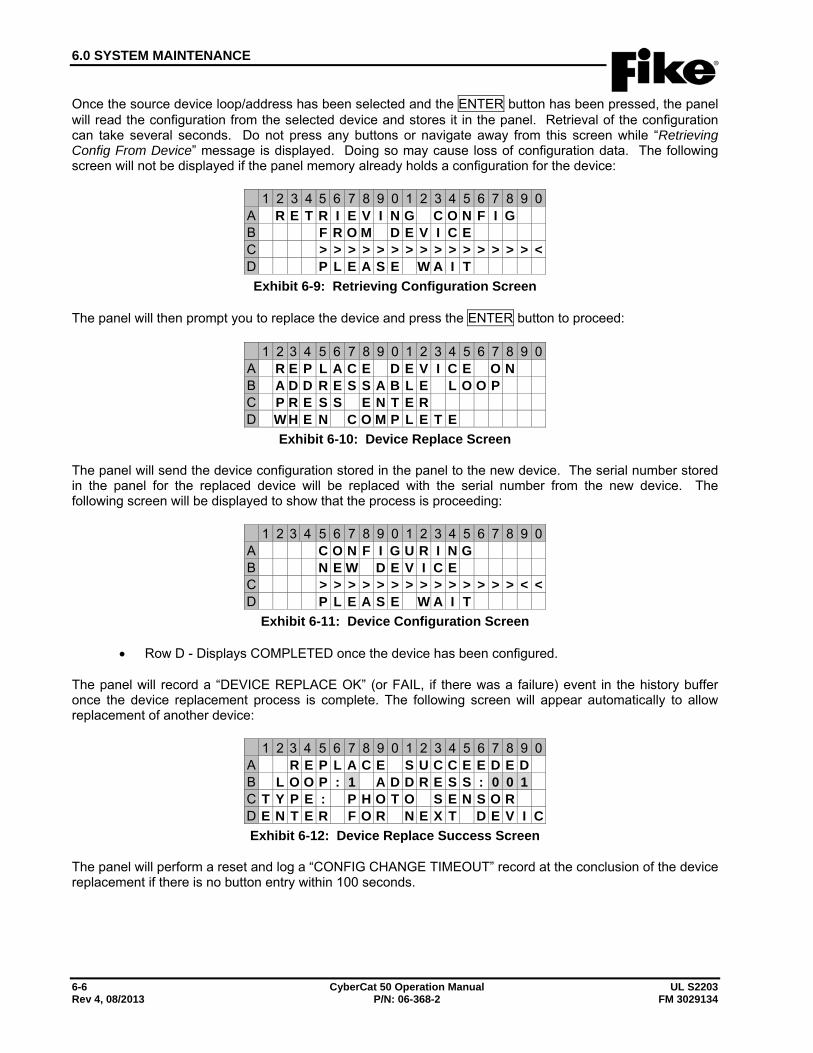
6.0 SYSTEM MAINTENANCE
6-6 CyberCat 50 Operation Manual UL S2203 Rev 4, 08/2013 P/N: 06-368-2 FM 3029134
Once the source device loop/address has been selected and the ENTER button has been pressed, the panel will read the configuration from the selected device and stores it in the panel. Retrieval of the configuration can take several seconds. Do not press any buttons or navigate away from this screen while “Retrieving Config From Device” message is displayed. Doing so may cause loss of configuration data. The following screen will not be displayed if the panel memory already holds a configuration for the device:
1 2 3 4 5 6 7 8 9 0 1 2 3 4 5 6 7 8 9 0A R E T R I E V I N G C O N F I GB F R O M D E V I C EC > > > > > > > > > > > > > > > <D P L E A S E W A I TExhibit 6-9: Retrieving Configuration Screen
The panel will then prompt you to replace the device and press the ENTER button to proceed:
1 2 3 4 5 6 7 8 9 0 1 2 3 4 5 6 7 8 9 0A R E P L A C E D E V I C E O NB A D D R E S S A B L E L O O PC P R E S S E N T E RD W H E N C O M P L E T E
Exhibit 6-10: Device Replace Screen
The panel will send the device configuration stored in the panel to the new device. The serial number stored in the panel for the replaced device will be replaced with the serial number from the new device. The following screen will be displayed to show that the process is proceeding:
1 2 3 4 5 6 7 8 9 0 1 2 3 4 5 6 7 8 9 0A C O N F I G U R I N GB N E W D E V I C EC > > > > > > > > > > > > > > < <D P L E A S E W A I T
Exhibit 6-11: Device Configuration Screen
• Row D - Displays COMPLETED once the device has been configured.
The panel will record a “DEVICE REPLACE OK” (or FAIL, if there was a failure) event in the history buffer once the device replacement process is complete. The following screen will appear automatically to allow replacement of another device:
1 2 3 4 5 6 7 8 9 0 1 2 3 4 5 6 7 8 9 0A R E P L A C E S U C C E E D E DB L O O P : 1 A D D R E S S : 0 0 1C T Y P E : P H O T O S E N S O RD E N T E R F O R N E X T D E V I CExhibit 6-12: Device Replace Success Screen
The panel will perform a reset and log a “CONFIG CHANGE TIMEOUT” record at the conclusion of the device replacement if there is no button entry within 100 seconds.
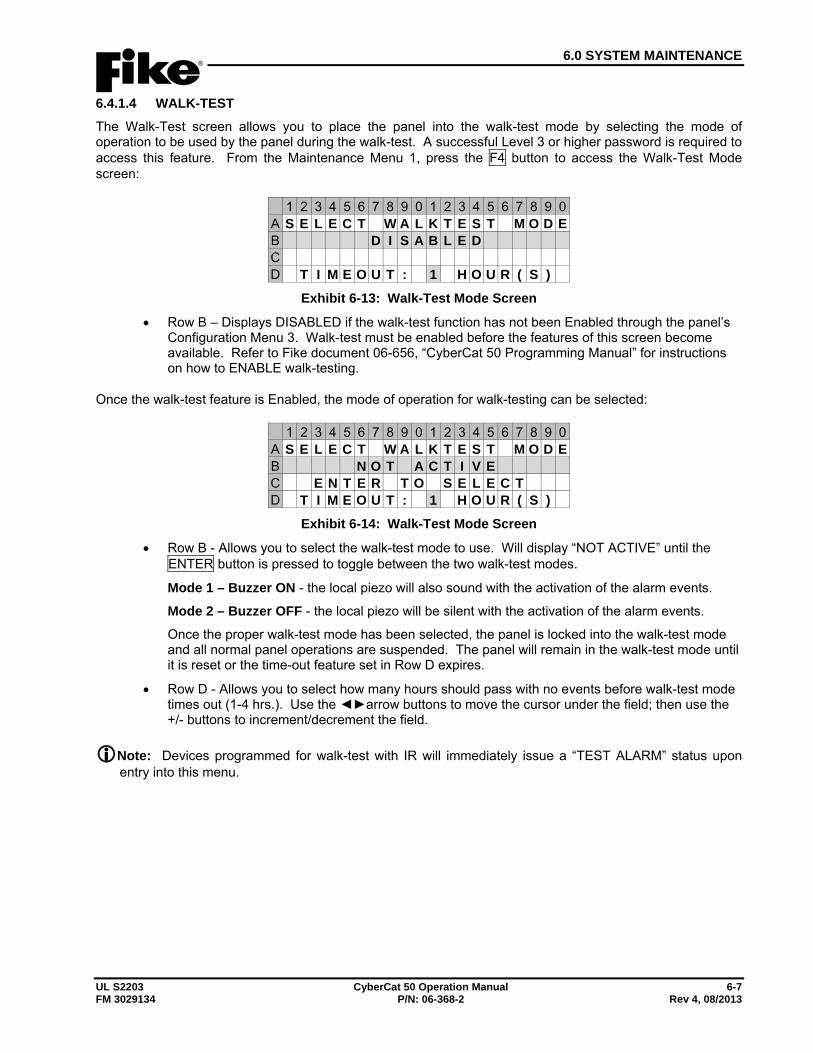
6.0 SYSTEM MAINTENANCE
UL S2203 CyberCat 50 Operation Manual 6-7 FM 3029134 P/N: 06-368-2 Rev 4, 08/2013
6.4.1.4 WALK-TEST The Walk-Test screen allows you to place the panel into the walk-test mode by selecting the mode of operation to be used by the panel during the walk-test. A successful Level 3 or higher password is required to access this feature. From the Maintenance Menu 1, press the F4 button to access the Walk-Test Mode screen:
1 2 3 4 5 6 7 8 9 0 1 2 3 4 5 6 7 8 9 0A S E L E C T W A L K T E S T M O D EB D I S A B L E DC D T I M E O U T : 1 H O U R ( S )
Exhibit 6-13: Walk-Test Mode Screen
• Row B – Displays DISABLED if the walk-test function has not been Enabled through the panel’s Configuration Menu 3. Walk-test must be enabled before the features of this screen become available. Refer to Fike document 06-656, “CyberCat 50 Programming Manual” for instructions on how to ENABLE walk-testing.
Once the walk-test feature is Enabled, the mode of operation for walk-testing can be selected:
1 2 3 4 5 6 7 8 9 0 1 2 3 4 5 6 7 8 9 0A S E L E C T W A L K T E S T M O D EB N O T A C T I V EC E N T E R T O S E L E C TD T I M E O U T : 1 H O U R ( S )
Exhibit 6-14: Walk-Test Mode Screen
• Row B - Allows you to select the walk-test mode to use. Will display “NOT ACTIVE” until the ENTER button is pressed to toggle between the two walk-test modes.
Mode 1 – Buzzer ON - the local piezo will also sound with the activation of the alarm events.
Mode 2 – Buzzer OFF - the local piezo will be silent with the activation of the alarm events.
Once the proper walk-test mode has been selected, the panel is locked into the walk-test mode and all normal panel operations are suspended. The panel will remain in the walk-test mode until it is reset or the time-out feature set in Row D expires.
• Row D - Allows you to select how many hours should pass with no events before walk-test mode times out (1-4 hrs.). Use the ◄►arrow buttons to move the cursor under the field; then use the +/- buttons to increment/decrement the field.
Note: Devices programmed for walk-test with IR will immediately issue a “TEST ALARM” status upon entry into this menu.
6.0 SYSTEM MAINTENANCE
6-8 CyberCat 50 Operation Manual UL S2203 Rev 4, 08/2013 P/N: 06-368-2 FM 3029134
Input Devices: By default, all input devices (i.e., sensors and monitor modules) will participate in a system walk-test. Sensor devices (i.e., photo, photo/heat, photo/duct, ionization and heat sensors) can be configured using the panel’s configuration software C-Linx to allow for walk-testing using canned smoke or Fike’s IR tool. The IR tool must be used for duct detector walk-testing. Devices may only be activated once during the walk-test mode. Sensors indicate that they are in the walk-test mode by blinking their LEDs green then red when tested. Sensor LEDs will return to normal operation (flash green every 5 seconds) when alarm condition clear.
Output Devices: Each output device (i.e., control module, relay module and NAC) can be individually programmed to participate in a system walk-test. Outputs will activate continuous (4 second duration) if programmed for the specific Zone and State of the activated input device. This allows you to get an audible feedback from system output devices each time a device is tested. By default, here is how the output devices come configured:
Control Module (P/N 55-042/55-047): Configured to respond to walk-test Relay Module (P/N 55-043/55-048): Configured NOT to respond to walk-test NAC1 (P10) and NAC2 (P11): Configured to respond to walk-test
A. PANEL WALK-TEST When walk-test is executed from control panel, all devices programmed for walk-test will enter the walk-test mode. Utilize the following procedure to perform the walk-test:
1. Enable walk-test operation from the control panel’s Maintenance Menu, F5-Maint > F4-WALKTS. If the screen indicates walk-test DISABLED, utilize the panel’s Configuration menu F1-CONFIG > F6-MENU 2 > F6-MENU 3 > F2-WALK to ENABLE walk-test operation for the panel. This requires an administrator level password to change.
Note: Sensors programmed for walk-test with IR will automatically issue a TEST ALARM message upon activation of the walk-test mode through the control panel. Sensors will indicate that they are in the walk-test mode by blinking their LEDs green then red continuously until the control panel is reset.
2. Proceed to the first device to be tested.
3. Activate the device using canned smoke (detectors) or manual activation (monitor modules). Verify alternating red and green LEDs on device.
4. Device broadcasts a TEST ALARM message. Message displays on the control panel LCD and remote displays (if applicable).
5. Audible devices programmed to respond to this device’s activation turn on for 4 seconds (continuous).
6. When test smoke clears from a sensor or after a monitor module is deactivated, device being tested will exit the test mode and the device LED returns to normal operation (flash green every 5 seconds).
7. After all devices are tested, download the panel history for testing records.
8. Reset the control panel to return it to normal operation. Panel will be reset automatically after a maximum of 4 hours.
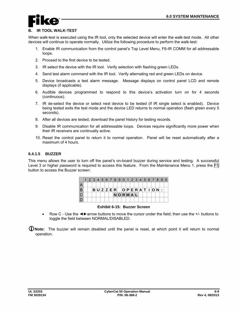
6.0 SYSTEM MAINTENANCE
UL S2203 CyberCat 50 Operation Manual 6-9 FM 3029134 P/N: 06-368-2 Rev 4, 08/2013
B. IR TOOL WALK-TEST When walk-test is executed using the IR tool, only the selected device will enter the walk-test mode. All other devices will continue to operate normally. Utilize the following procedure to perform the walk-test:
1. Enable IR communication from the control panel’s Top Level Menu, F6-IR COMM for all addressable loops.
2. Proceed to the first device to be tested.
3. IR select the device with the IR tool. Verify selection with flashing green LEDs.
4. Send test alarm command with the IR tool. Verify alternating red and green LEDs on device.
5. Device broadcasts a test alarm message. Message displays on control panel LCD and remote displays (if applicable).
6. Audible devices programmed to respond to this device’s activation turn on for 4 seconds (continuous).
7. IR de-select the device or select next device to be tested (if IR single select is enabled). Device being tested exits the test mode and the device LED returns to normal operation (flash green every 5 seconds).
8. After all devices are tested, download the panel history for testing records.
9. Disable IR communication for all addressable loops. Devices require significantly more power when their IR receivers are continually active.
10. Reset the control panel to return it to normal operation. Panel will be reset automatically after a maximum of 4 hours.
6.4.1.5 BUZZER This menu allows the user to turn off the panel’s on-board buzzer during service and testing. A successful Level 3 or higher password is required to access this feature. From the Maintenance Menu 1, press the F5 button to access the Buzzer screen:
1 2 3 4 5 6 7 8 9 0 1 2 3 4 5 6 7 8 9 0A B B U Z Z E R O P E R A T I O N :C N O R M A LD
Exhibit 6-15: Buzzer Screen
• Row C - Use the ◄►arrow buttons to move the cursor under the field; then use the +/- buttons to toggle the field between NORMAL/DISABLED.
Note: The buzzer will remain disabled until the panel is reset, at which point it will return to normal operation.
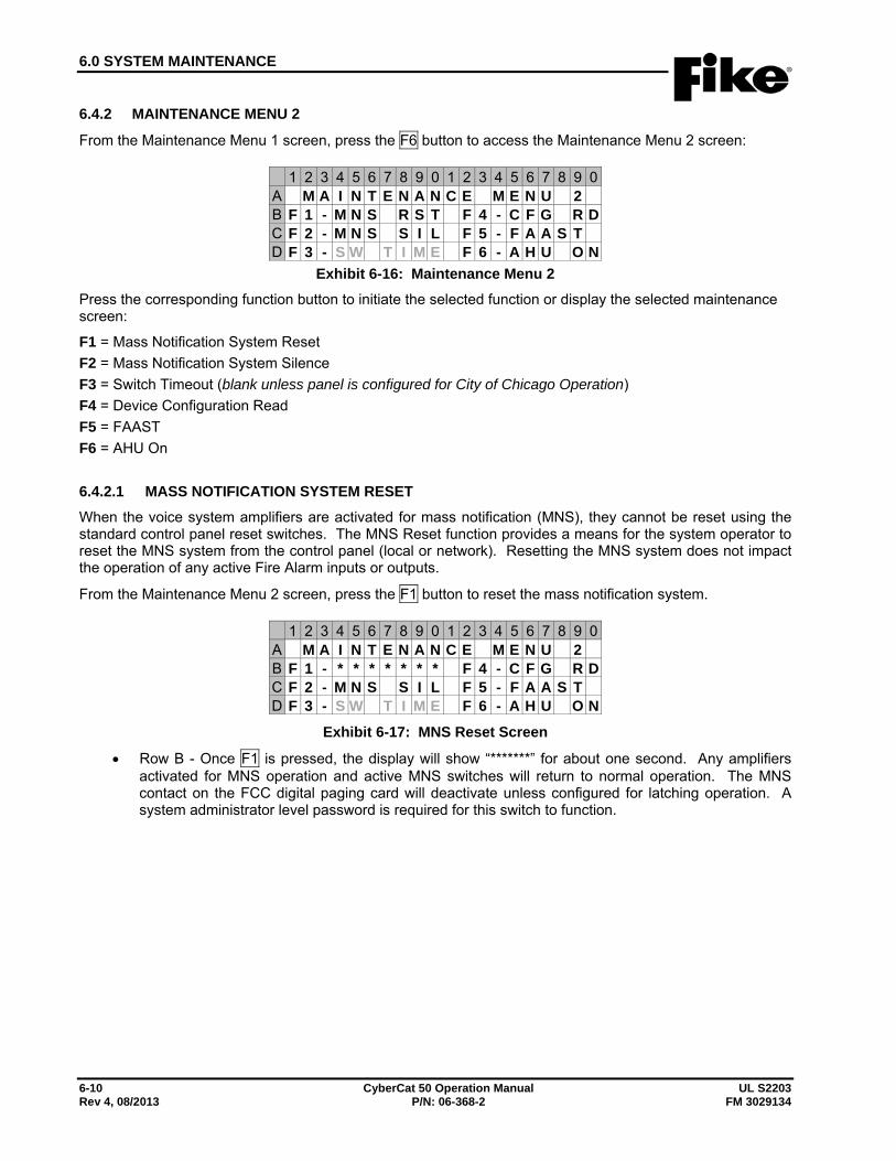
6.0 SYSTEM MAINTENANCE
6-10 CyberCat 50 Operation Manual UL S2203 Rev 4, 08/2013 P/N: 06-368-2 FM 3029134
6.4.2 MAINTENANCE MENU 2
From the Maintenance Menu 1 screen, press the F6 button to access the Maintenance Menu 2 screen:
1 2 3 4 5 6 7 8 9 0 1 2 3 4 5 6 7 8 9 0A M A I N T E N A N C E M E N U 2B F 1 - M N S R S T F 4 - C F G R DC F 2 - M N S S I L F 5 - F A A S TD F 3 - S W T I M E F 6 - A H U O N
Exhibit 6-16: Maintenance Menu 2 Press the corresponding function button to initiate the selected function or display the selected maintenance screen:
F1 = Mass Notification System Reset F2 = Mass Notification System Silence F3 = Switch Timeout (blank unless panel is configured for City of Chicago Operation) F4 = Device Configuration Read F5 = FAAST F6 = AHU On
6.4.2.1 MASS NOTIFICATION SYSTEM RESET When the voice system amplifiers are activated for mass notification (MNS), they cannot be reset using the standard control panel reset switches. The MNS Reset function provides a means for the system operator to reset the MNS system from the control panel (local or network). Resetting the MNS system does not impact the operation of any active Fire Alarm inputs or outputs.
From the Maintenance Menu 2 screen, press the F1 button to reset the mass notification system.
1 2 3 4 5 6 7 8 9 0 1 2 3 4 5 6 7 8 9 0A M A I N T E N A N C E M E N U 2B F 1 - * * * * * * * F 4 - C F G R DC F 2 - M N S S I L F 5 - F A A S TD F 3 - S W T I M E F 6 - A H U O N
Exhibit 6-17: MNS Reset Screen
• Row B - Once F1 is pressed, the display will show “*******” for about one second. Any amplifiers activated for MNS operation and active MNS switches will return to normal operation. The MNS contact on the FCC digital paging card will deactivate unless configured for latching operation. A system administrator level password is required for this switch to function.
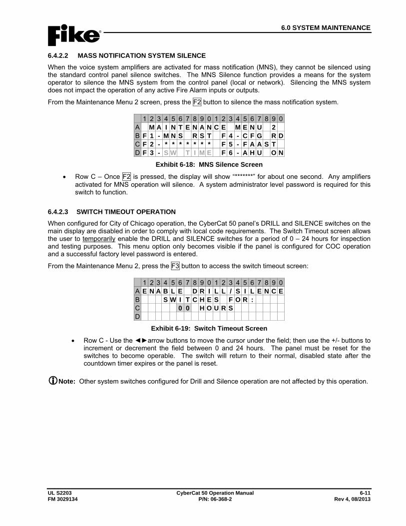
6.0 SYSTEM MAINTENANCE
UL S2203 CyberCat 50 Operation Manual 6-11 FM 3029134 P/N: 06-368-2 Rev 4, 08/2013
6.4.2.2 MASS NOTIFICATION SYSTEM SILENCE When the voice system amplifiers are activated for mass notification (MNS), they cannot be silenced using the standard control panel silence switches. The MNS Silence function provides a means for the system operator to silence the MNS system from the control panel (local or network). Silencing the MNS system does not impact the operation of any active Fire Alarm inputs or outputs.
From the Maintenance Menu 2 screen, press the F2 button to silence the mass notification system.
1 2 3 4 5 6 7 8 9 0 1 2 3 4 5 6 7 8 9 0A M A I N T E N A N C E M E N U 2B F 1 - M N S R S T F 4 - C F G R DC F 2 - * * * * * * * F 5 - F A A S TD F 3 - S W T I M E F 6 - A H U O N
Exhibit 6-18: MNS Silence Screen
• Row C – Once F2 is pressed, the display will show “*******” for about one second. Any amplifiers activated for MNS operation will silence. A system administrator level password is required for this switch to function.
6.4.2.3 SWITCH TIMEOUT OPERATION When configured for City of Chicago operation, the CyberCat 50 panel’s DRILL and SILENCE switches on the main display are disabled in order to comply with local code requirements. The Switch Timeout screen allows the user to temporarily enable the DRILL and SILENCE switches for a period of 0 – 24 hours for inspection and testing purposes. This menu option only becomes visible if the panel is configured for COC operation and a successful factory level password is entered.
From the Maintenance Menu 2, press the F3 button to access the switch timeout screen:
1 2 3 4 5 6 7 8 9 0 1 2 3 4 5 6 7 8 9 0A E N A B L E D R I L L / S I L E N C EB S W I T C H E S F O R :C 0 0 H O U R SD
Exhibit 6-19: Switch Timeout Screen
• Row C - Use the ◄►arrow buttons to move the cursor under the field; then use the +/- buttons to increment or decrement the field between 0 and 24 hours. The panel must be reset for the switches to become operable. The switch will return to their normal, disabled state after the countdown timer expires or the panel is reset.
Note: Other system switches configured for Drill and Silence operation are not affected by this operation.
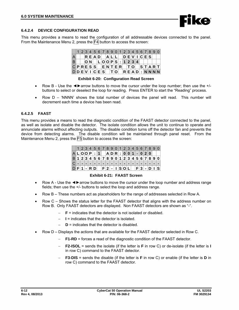
6.0 SYSTEM MAINTENANCE
6-12 CyberCat 50 Operation Manual UL S2203 Rev 4, 08/2013 P/N: 06-368-2 FM 3029134
6.4.2.4 DEVICE CONFIGURATION READ This menu provides a means to read the configuration of all addressable devices connected to the panel. From the Maintenance Menu 2, press the F4 button to access the screen:
1 2 3 4 5 6 7 8 9 0 1 2 3 4 5 6 7 8 9 0A R E A D A L L D E V I C E SB O N L O O P S : 1 2 3 4C P R E S S E N T E R T O S T A R TD D E V I C E S T O R E A D : N N N N
Exhibit 6-20: Configuration Read Screen
• Row B - Use the ◄►arrow buttons to move the cursor under the loop number; then use the +/- buttons to select or deselect the loop for reading. Press ENTER to start the “Reading” process.
• Row D – ‘NNNN’ shows the total number of devices the panel will read. This number will decrement each time a device has been read.
6.4.2.5 FAAST This menu provides a means to read the diagnostic condition of the FAAST detector connected to the panel, as well as isolate and disable the detector. The isolate condition allows the unit to continue to operate and annunciate alarms without affecting outputs. The disable condition turns off the detector fan and prevents the device from detecting alarms. The disable condition will be maintained through panel reset. From the Maintenance Menu 2, press the F5 button to access the screen:
1 2 3 4 5 6 7 8 9 0 1 2 3 4 5 6 7 8 9 0A L O O P : 1 A D R : 0 0 1 - 0 2 0B 1 2 3 4 5 6 7 8 9 0 1 2 3 4 5 6 7 8 9 0C - - - - - - - - - - - - - - - - - - - -D F 1 - R D F 2 - I S O L F 3 - D I S
Exhibit 6-21: FAAST Screen
• Row A - Use the ◄►arrow buttons to move the cursor under the loop number and address range fields; then use the +/- buttons to select the loop and address range.
• Row B – These numbers act as placeholders for the range of addresses selected in Row A.
• Row C – Shows the status letter for the FAAST detector that aligns with the address number on Row B. Only FAAST detectors are displayed. Non FAAST detectors are shown as “-“.
− F = indicates that the detector is not isolated or disabled. − I = indicates that the detector is isolated. − D = indicates that the detector is disabled.
• Row D – Displays the actions that are available for the FAAST detector selected in Row C.
− F1-RD = forces a read of the diagnostic condition of the FAAST detector.
− F2-ISOL = sends the isolate (if the letter is F in row C) or de-isolate (if the letter is I in row C) command to the FAAST detector.
− F3-DIS = sends the disable (if the letter is F in row C) or enable (if the letter is D in row C) command to the FAAST detector.
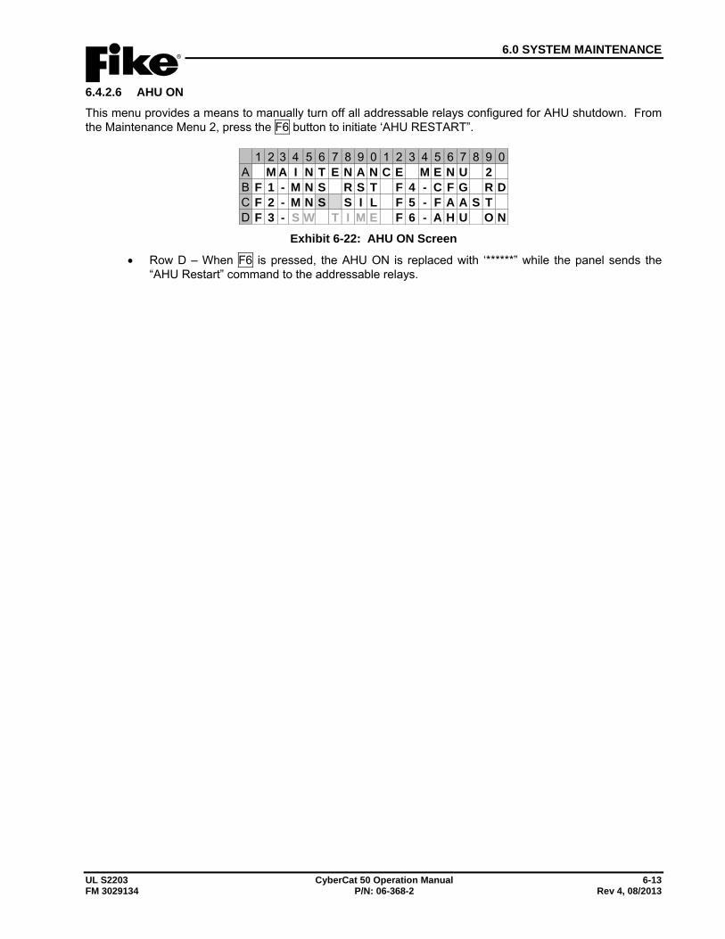
6.0 SYSTEM MAINTENANCE
UL S2203 CyberCat 50 Operation Manual 6-13 FM 3029134 P/N: 06-368-2 Rev 4, 08/2013
6.4.2.6 AHU ON This menu provides a means to manually turn off all addressable relays configured for AHU shutdown. From the Maintenance Menu 2, press the F6 button to initiate ‘AHU RESTART”.
1 2 3 4 5 6 7 8 9 0 1 2 3 4 5 6 7 8 9 0A M A I N T E N A N C E M E N U 2B F 1 - M N S R S T F 4 - C F G R DC F 2 - M N S S I L F 5 - F A A S TD F 3 - S W T I M E F 6 - A H U O N
Exhibit 6-22: AHU ON Screen
• Row D – When F6 is pressed, the AHU ON is replaced with ‘******” while the panel sends the “AHU Restart” command to the addressable relays.
6.0 SYSTEM MAINTENANCE
6-14 CyberCat 50 Operation Manual UL S2203 Rev 4, 08/2013 P/N: 06-368-2 FM 3029134
Reserved for future use.
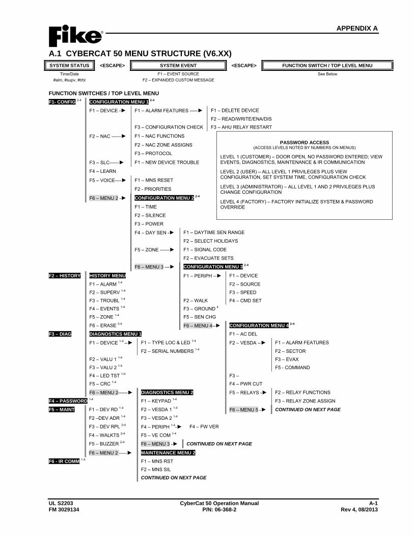
APPENDIX A
UL S2203 CyberCat 50 Operation Manual A-1 FM 3029134 P/N: 06-368-2 Rev 4, 08/2013
A.1 CYBERCAT 50 MENU STRUCTURE (V6.XX) SYSTEM STATUS <ESCAPE> SYSTEM EVENT <ESCAPE> FUNCTION SWITCH / TOP LEVEL MENU
Time/Date F1 – EVENT SOURCE See Below #alm, #supv, #trbl F2 – EXPANDED CUSTOM MESSAGE
FUNCTION SWITCHES / TOP LEVEL MENU F1- CONFIG 2-4 CONFIGURATION MENU 1 2-4
F1 – DEVICE -► F1 – ALARM FEATURES -----► F1 – DELETE DEVICE
F2 – READ/WRITE/ENA/DIS
F3 – CONFIGURATION CHECK F3 – AHU RELAY RESTART
F2 – NAC ------► F1 – NAC FUNCTIONS PASSWORD ACCESS
(ACCESS LEVELS NOTED BY NUMBERS ON MENUS)
LEVEL 1 (CUSTOMER) – DOOR OPEN, NO PASSWORD ENTERED; VIEW EVENTS, DIAGNOSTICS, MAINTENANCE & IR COMMUNICATION
LEVEL 2 (USER) – ALL LEVEL 1 PRIVILEGES PLUS VIEW CONFIGURATION, SET SYSTEM TIME, CONFIGURATION CHECK
LEVEL 3 (ADMINISTRATOR) – ALL LEVEL 1 AND 2 PRIVILEGES PLUS CHANGE CONFIGURATION
LEVEL 4 (FACTORY) – FACTORY INITIALIZE SYSTEM & PASSWORD OVERRIDE
F2 – NAC ZONE ASSIGNS
F3 – PROTOCOL
F3 – SLC------► F1 – NEW DEVICE TROUBLE
F4 – LEARN
F5 – VOICE----► F1 – MNS RESET
F2 - PRIORITIES
F6 – MENU 2 -► CONFIGURATION MENU 2 2-4
F1 – TIME
F2 – SILENCE
F3 – POWER
F4 – DAY SEN -► F1 – DAYTIME SEN RANGE
F2 – SELECT HOLIDAYS
F5 – ZONE ------► F1 – SIGNAL CODE
F2 – EVACUATE SETS
F6 – MENU 3 ---► CONFIGURATION MENU 3 2-4
F2 – HISTORY HISTORY MENU F1 – PERIPH --► F1 – DEVICE
F1 – ALARM 1-4 F2 – SOURCE
F2 – SUPERV 1-4 F3 – SPEED
F3 – TROUBL 1-4 F2 – WALK F4 – CMD SET
F4 – EVENTS 1-4 F3 – GROUND 4
F5 – ZONE 1-4 F5 – SEN CHG
F6 – ERASE 3-4 F6 – MENU 4--► CONFIGURATION MENU 4 2-4
F3 – DIAG DIAGNOSTICS MENU 1 F1 – AC DEL
F1 – DEVICE 1-4 --► F1 – TYPE LOC & LED 1-4 F2 – VESDA --► F1 – ALARM FEATURES
F2 – SERIAL NUMBERS 1-4 F2 – SECTOR
F2 – VALU 1 1-4 F3 – EVAX
F3 – VALU 2 1-4 F5 - COMMAND
F4 – LED TST 1-4 F3 –
F5 – CRC 1-4 F4 – PWR CUT
F6 – MENU 2------► DIAGNOSTICS MENU 2 F5 – RELAYS -► F2 – RELAY FUNCTIONS
F4 – PASSWORD 1-4 F1 – KEYPAD 1-4 F3 – RELAY ZONE ASSIGN
F5 – MAINT F1 – DEV RD 1-4 F2 – VESDA 1 1-4 F6 – MENU 5 -► CONTINUED ON NEXT PAGE
F2 –DEV ADR 1-4 F3 – VESDA 2 1-4
F3 – DEV RPL 2-4 F4 – PERIPH 1-4-► F4 – FW VER
F4 – WALKTS 2-4 F5 – VE COM 1-4
F5 – BUZZER 2-4 F6 – MENU 3 -► CONTINUED ON NEXT PAGE
F6 – MENU 2 -----► MAINTENANCE MENU 2
F6 - IR COMM 1-4 F1 – MNS RST
F2 – MNS SIL
CONTINUED ON NEXT PAGE
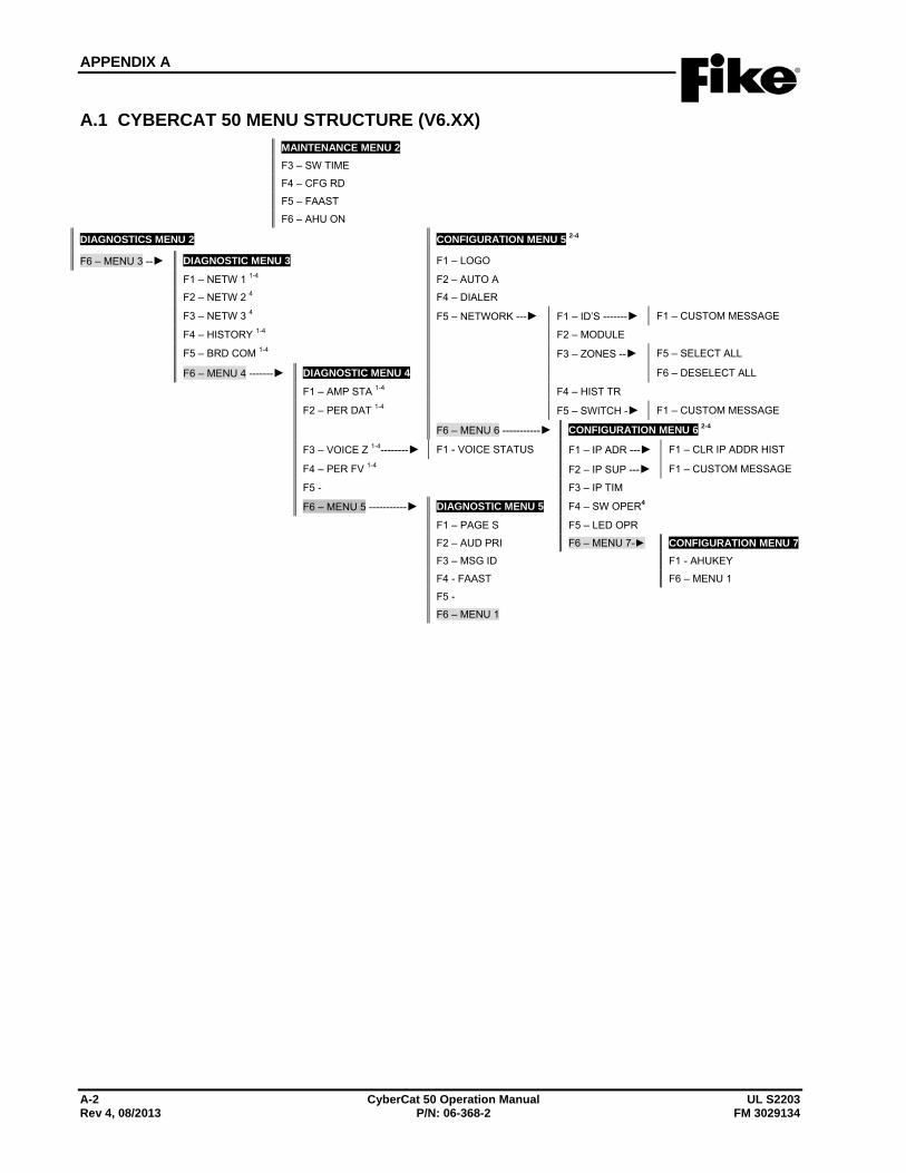
APPENDIX A
A-2 CyberCat 50 Operation Manual UL S2203 Rev 4, 08/2013 P/N: 06-368-2 FM 3029134
A.1 CYBERCAT 50 MENU STRUCTURE (V6.XX) MAINTENANCE MENU 2
F3 – SW TIME
F4 – CFG RD
F5 – FAAST
F6 – AHU ON
DIAGNOSTICS MENU 2 CONFIGURATION MENU 5 2-4
F6 – MENU 3 --► DIAGNOSTIC MENU 3 F1 – LOGO
F1 – NETW 1 1-4 F2 – AUTO A
F2 – NETW 2 4 F4 – DIALER
F3 – NETW 3 4 F5 – NETWORK ---► F1 – ID’S -------► F1 – CUSTOM MESSAGE
F4 – HISTORY 1-4 F2 – MODULE
F5 – BRD COM 1-4 F3 – ZONES --► F5 – SELECT ALL
F6 – MENU 4 -------► DIAGNOSTIC MENU 4 F6 – DESELECT ALL
F1 – AMP STA 1-4 F4 – HIST TR
F2 – PER DAT 1-4 F5 – SWITCH -► F1 – CUSTOM MESSAGE
F6 – MENU 6 -----------► CONFIGURATION MENU 6 2-4
F3 – VOICE Z 1-4--------► F1 - VOICE STATUS F1 – IP ADR ---► F1 – CLR IP ADDR HIST
F4 – PER FV 1-4 F2 – IP SUP ---► F1 – CUSTOM MESSAGE
F5 - F3 – IP TIM
F6 – MENU 5 -----------► DIAGNOSTIC MENU 5 F4 – SW OPER4
F1 – PAGE S F5 – LED OPR
F2 – AUD PRI F6 – MENU 7-► CONFIGURATION MENU 7 F3 – MSG ID F1 - AHUKEY
F4 - FAAST F6 – MENU 1
F5 -
F6 – MENU 1


704 SW 10th Street P.O. Box 610 Blue Springs, Missouri 64013
Tel: (816) 229-3405 Fax: (816) 229-0314 www.fike.com