valvulas de mariposa con asiento elastico … 2015_1.pdf · valvulas para el control de fluidos...
TRANSCRIPT
VALVULAS PARA EL CONTROL DE FLUIDOS VALVES FOR PROCESS CONTROL
VALVULAS DE MARIPOSA CON ASIENTO ELASTICO REEMPLAZA BLE
BUTTERFLY VALVES WITH RESILIENT REPLACEABLE SEAT Las válvulas de mariposa DECOVAL series B10 y B30, son fácilmente adaptables y presentan numerosas ventajas y aplicaciones, entre las que destacan:
The butterfly valves DECOVAL series B10 & B30, are easily adaptable and present numerous advantages and applications, including:
VENTAJAS: • Dimensiones y pesos reducidos. • Montaje y desmontaje rápido. • Bajos costes de instalación y mantenimiento. • Reducida pérdida de carga. • Bajo par de apertura y maniobra. • Posibilidad de regulación manual y automática. • Estanqueidad total.
ADVANTAGES: • Low weight and dimensions. • Easy disassembly and assembly. • Low cost instalation and maintenance. • Low pressure drop. • Low break away and run torque. • Possibility of manual and automatic regulation. • Bubble tight shut-off.
APLICACIONES: • Tratamiento y distribución de agua. • Calefacción, ventilación y aire acondicionado. • Protección contra incendios. • Agricultura y riegos. • Minería y fundiciones. • Construcción naval. • Centrales térmicas, hidroeléctricas y nucleares. • Plantas siderúrgicas y de alúmina. • Plantas químicas y petroquímicas. • Plantas cerveceras e industrias de bebidas. • Plantas papeleras y de celulosa. • Refinerías de azúcar. • Procesos farmacéuticos y de alimentación. • Transporte de productos secos y pulverulentos. • Procesos de gas y petróleo.
APPLICATIONS: • Water treatment and distributión system. • Heating, ventilating and air conditioning. • Fire protection system. • Farming and irrigation. • Mining and foundries. • Shipbuilding and off-shore industries. • Power stations. • Steel and aluminium plants. • Chemical & petrochemical plants. • Breweries and beverage. • Pulp and paper plants. • Sugar industries. • Food and Pharmaceutical processing. • Bulk Handling fluids. • Oil and gas process.
FLUIDOS: • Líquidos, gases y sólidos.
FLUIDS: • Liquids, gas and solids.
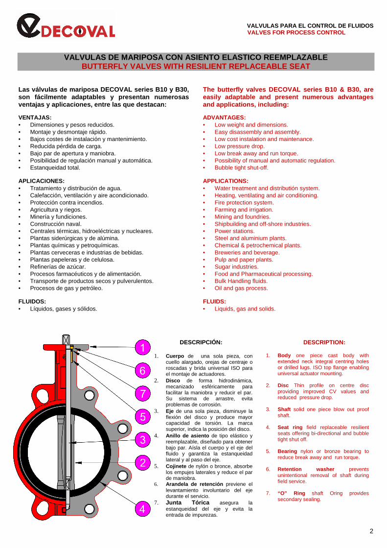
DESCRIPCIÓN: 1. Cuerpo de una sola pieza, con
cuello alargado, orejas de centraje o roscadas y brida universal ISO para el montaje de actuadores.
2. Disco de forma hidrodinámica, mecanizado esféricamente para facilitar la maniobra y reducir el par. Su sistema de arrastre, evita problemas de corrosión.
3. Eje de una sola pieza, disminuye la flexión del disco y produce mayor capacidad de torsión. La marca superior, indica la posición del disco.
4. Anillo de asiento de tipo elástico y reemplazable, diseñado para obtener bajo par. Aísla el cuerpo y el eje del fluido y garantiza la estanqueidad lateral y al paso del eje.
5. Cojinete de nylón o bronce, absorbe los empujes laterales y reduce el par de maniobra.
6. Arandela de retención previene el levantamiento involuntario del eje durante el servicio.
7. Junta Tórica asegura la estanqueidad del eje y evita la entrada de impurezas.
DESCRIPTION:
1. Body one piece cast body with extended neck integral centring holes or drilled lugs. ISO top flange enabling universal actuator mounting.
2. Disc Thin profile on centre disc providing improved CV values and reduced pressure drop.
3. Shaft solid one piece blow out proof shaft.
4. Seat ring field replaceable resilient seats offering bi-directional and bubble tight shut off.
5. Bearing nylon or bronze bearing to reduce break away and run torque.
6. Retention washer prevents unintentional removal of shaft during field service.
7. “O” Ring shaft Oring provides secondary sealing.
2
VALVULAS PARA EL CONTROL DE FLUIDOS VALVES FOR PROCESS CONTROL NORMAS DE FABRICACION Y MONTAJE MANUFACTURING STANDARD AND ASSEMBLY DISEÑO: ISO 10631, EN 593 DIMENSIONES CARA-CARA: ISO 5752, EN 558, DIN 3302, NFE 29305, BS 5155, API 609, MSS SP 67. BRIDA DE ACCIONAMIENTOS: ISO 5211, EN 12116, DIN 3337, NFE 29402, BS 5840. SALIDA DE EJE: ISO 5211, DIN 3337, BS 5840. MARCAS: ISO 5209, EN 19. PRUEBAS: ISO 5208, EN 12266, DIN 3230, NFE 29311. • Estanqueidad en cierre: 1,1 x PN. • Resistencia del cuerpo: 1,5 x PN. MONTAJE ENTRE BRIDAS: ISO 7005, EN 1092, DIN 2501, NFE 29203, BS 4504 ( PN-6/10/16 ). ANSI B16.1- B16.5, BS 10 - AS 2129 ( tablas D y E ). JIS 2238-2239 ( 5K/10K/16K ).
DESIGN : ISO 10631, EN 593 FACE-FACE DIMENSIONS: ISO 5752, EN 558, DIN 3302, NFE 29305, BS 5155, API 609, MSS SP 67. ACTUATORS FLANGE: ISO 5211, EN 12116, DIN 3337, NFE 29402, BS 5840. END SHAFT: ISO 5211, DIN 3337, BS 5840. MARKINGS: ISO 5209, EN 19. TESTS: ISO 5208, EN 12266, DIN 3230, NFE 29311. • Tightness: 1,1 x PN. • Body strength: 1.5 x PN. MOUNTING BETWEEN FLANGES: ISO 7005, EN 1092, DIN 2501, NFE 29203, BS 4504 ( PN-6/10/16 ). ANSI B.16.- B.16.5, BS 10 - AS 2129 ( tables D/E ). JIS 2238-2239 ( 5K/10K/16K ).
MODELOS Y CARACTERISTICAS MODEL AND CHARACTERISTICS B10 = WAFER / B30 = LUG B10 = WAFER / B30 = LUG PRESION DE SERVICIO: PRESSURE RATING: STD. DN. 040 ÷150 = 16 bar. STD. DN. 040 ÷150 = 16 bar. STD. DN. 200 ÷300 = 10 bar. ( bajo demanda 16 bar. ) STD. DN. 200 ÷300 = 10 bar. ( on request 16 bar. ) VACIO: 0,2 bar absolutos (según fluido y temperatura) VACUUM: 0,2 bar absolutes (acc. fluid and temperature) TEMPERATURA: TEMPERATURE: STD. -20 + 95° C (con EPDM) STD. -20 + 95° C (with EPDM) MAX. -40 + 200° C (según materiales ) MAX. -40 + 200° C (according to materials)
CODIFICACION ORDERING CODE
EJEMPLO: B10 . 100 . 43 – 22E . 22R . 41 . E – PG230 . 0511
EXAMPLE: (1) (2) (3)(4) (5)(9) (6)(9) (7) (8) Mando / Operator
(1) Modelo Model B10 = WAFER B10 = WAFER B30 = LUG B30 = LUG
(2) Diámetro (DN) Diameter (ND)
040 – 300 mm. 040 – 300 mm. (3) Presión (PN) Pressure (NP)
0 = 0 bar 0 = 0 bar 1 = 3 bar 1 = 3 bar 2 = 6 bar 2 = 6 bar 3 = 10 bar 3 = 10 bar 4 = 16 bar 4 = 16 bar
(4) Norma de bridas Flanges
1 = PN - 6 1 = PN - 6 2 = PN -10 2 = PN - 10 3 = PN -16 3 = PN - 16 4 = PN -20 4 = PN - 20 5 = JIS 5K 5 = JIS 5K 6 = JIS 10K 6 = JIS 10K 7 = JIS 16K 7 = JIS 16K A = ANSI 125/150 A = ANSI 125/150 D = AS/BS tabla D D =AS/BS table D E = AS/BS tabla E E = AS/BS table E
(5) Material del cuerpo Body material 12 Fundición Gris EN GJL 250 (JL1040) Cast Iron EN GJL 250 (JL1040) 22 F. Nodular EN GJS 400-15 (JS1030)
Ductile Iron EN GJS 400-15 (JS1030) (6) Material del disco Disc material
22 F. Nodular EN GJS 400-15 (JS1030) Ductile Iron EN GJS 400-15 (JS1030)
42 Ac. Inoxidable AISI-316 (1.4408) Stainless Steel AISI-316 (1.4408) 53 Bronce Alumínio EN CC333 G Aluminium Bronze EN CC333 G (7) Material del eje Shaft material
41 Ac. Inoxidable AISI-420 (1.4021) Stainless Steel AISI-420 (1.4021)
42 Ac. Inoxidable AISI-316 (1.4401) Stainless Steel AISI-316 (1.4401)
NOTA: Los materiales relacionados son los de fabricación estándar. Otros bajo pedido.
NOTE: Other materials on request.
(8) Material del asiento Seat material B Butilo Butyl E EPDM EPDM EC EPDM calor EPDM HT H Hypalón Hypalon N Nitrilo Nitrile NC Nitrilo carbx. Nitrile carboxylit NE Neopreno Neoprene NR Caucho natural Natural rubber S Silicona Silicone V Vitón Viton
(9) Recubrimientos Coatings
E Pintura epoxi Epoxy painting R Rilsan Rilsan H Halard Halard C Cromado Chrome P Pulido Polished NOTA: Otros tipos de caucho y recubrimiento, bajo pedido. NOTE: Other types of rubber and coating, on request.
3
VALVULAS PARA EL CONTROL DE FLUIDOS
VALVES FOR PROCESS CONTROL
VÁLVULAS VALVES
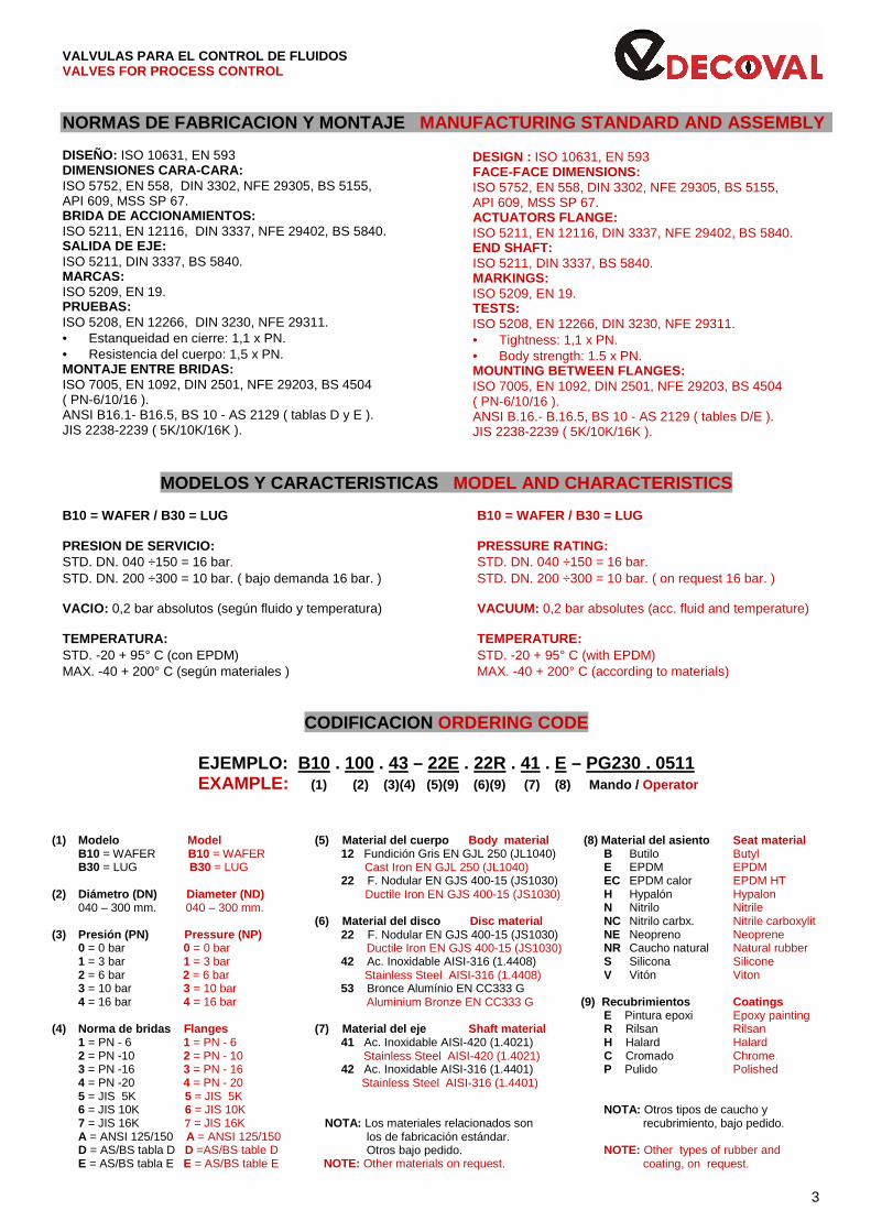
TIPO WAFER SERIE B10 – TIPO LUG SERIE B30 WAFER TYPE SERIES B-10 – LUG TYPE SERIES B30 Instalación entre bridas: DIN, ISO, EN, ANSI, etc. Mounting between flanges: DIN, ISO, EN, ANSI, etc. Presión de servicio máxima: 16 bar ( s / materiales ) Maximum working pressure: 16 bar ( acc. / materials ) Temperatura máxima: - 40 + 200 °C ( s / materiales ) Maximum temperature: - 40 + 200 °C ( acc. / materials )
Dimensiones (mm.) Dimensions (mm.)
DN
Válvula Valve Eje Shaft ISO 5211 Kgs.
A B1 B2 C D1 D2 E F G H I ISO ∅a ∅b ∅c nº d B10 B30
32/40 130 55 53 24,5 76 106 33 1,5 16 13 11 F05 65 50 7 4 10 1,50 1,80
50 135 63 62 27,5 94 119 43 2 16 13 11 F05 65 50 7 4 10 2,20 2,65
65 150 71,5 70,5 47,5 111 133 46 2 16 13 11 F05 65 50 7 4 10 2,90 3,35
80 160 91 89 66,7 127 178 46 2 19 13 11 F05 65 50 7 4 10 3,40 5,40
100 180 106 101 86,6 151 201 52 2,25 19 13 11 F05 65 50 7 4 10 4,80 7,30
125 196 121 116 113 180 232 56 2,5 19 17 14 F05 65 50 7 4 10 6,20 8,25
150 210 133 128 142 206 256 56 2,75 19 17 14 F07 90 70 9 4 12 7,75 9,70
200 240 164 161 191 261 323 60 3 24 21 17 F07 90 70 9 4 12 12 17,6
250 275 199 195 240 318 390 68 3,25 29 26,5 22 F10 125 102 11 4 15 21,8 27,9
300 310 233 229 289 372 458 78 3,5 29 26,5 22 F10 125 102 11 4 15 30,2 39,8
Nota: dimensiones y pesos a título informativo. Note: Weights & dimensions are only as information.
4
VALVULAS PARA EL CONTROL DE FLUIDOS VALVES FOR PROCESS CONTROL
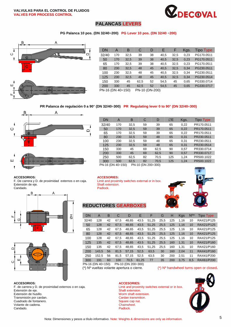
PALANCAS LEVERS
PG Palanca 10 pos. (DN 32/40 ÷200) PG Lever 10 pos. (DN 32/40 ÷200)
DN A B C D E F Kgs. Tipo Type 32/40 170 32,5 39 38 40,5 32,5 0,23 PG170.0511
50 170 32,5 39 38 40,5 32,5 0,23 PG170.0511
65 170 32,5 39 38 40,5 32,5 0,23 PG170.0511
80 230 32,5 48 45 40,5 32,5 0,34 PG230.0511
100 230 32,5 48 45 40,5 32,5 0,34 PG230.0511
125 230 32,5 48 45 40,5 32,5 0,34 PG230.0514
150 330 45 62,5 52 54,5 45 0,65 PG330.0714
200 330 45 62,5 52 54,5 45 0,65 PG330.0717 PN-16 (DN 40÷150) PN-10 (DN-200)
PR Palanca de regulación 0 a 90 ° (DN 32/40÷300) PR Regulating lever 0 to 90 ° (DN 32/40÷300)
DN A B C D ∅E Kgs. Tipo Type
32/40 170 32,5 59 39 65 0,22 PR170.0511 50 170 32,5 59 39 65 0,22 PR170.0511 65 170 32,5 59 39 65 0,22 PR170.0511 80 230 32,5 59 48 65 0,31 PR230.0511
100 230 32,5 59 48 65 0,31 PR230.0511 125 230 32,5 59 48 65 0,31 PR230.0514 150 330 45 69 62,5 90 0,57 PR330.0714 200 330 45 69 62,5 90 0,57 PR330.0717 250 500 62,5 82 70,5 125 1,24 PR500.1022 300 500 62,5 82 70,5 125 1,24 PR500.1022
PN-16 (DN 40÷150) PN-10 (DN 200÷300)
ACCESORIOS: ACCESORIES: F. De carrera y D. de proximidad externos o en caja. Limit and proximity switches external or in box. Extensión de eje. Shaft extension. Candado. Padlock.
REDUCTORES GEARBOXES
PN-16 (DN 40÷150) PN-10 (DN 200÷300) (*) Nº vueltas volante apertura o cierre. (*) Nº handwheel turns open or closed.
ACCESORIOS: ACCESORIES: F. de carrera y D. de proximidad externos o en caja. Limit and proximity switches external or in box. Extensión de eje. Shaft extension. Extensión de husillo. Worm shaft extension. Transmisión por cardan. Cardan transmition. Cuadrado de fontanero. Square cap nut. Volante de cadena. Chainwheel. Candado. Padlock.
Nota: Dimensiones y pesos a título informativo. Note: Weights & dimensions are only as information.
DN A B C D E F G H Kgs Nº* Tipo Type 32/40 128 42 67,5 48,65 43.5 51,25 25,5 125 1,16 10 RAX21/P125
50 128 42 67,5 48,65 43,5 51,25 25,5 125 1,16 10 RAX21/P125
65 128 42 67,5 48,65 43,5 51,25 25,5 125 1,16 10 RAX21/P125
80 128 42 67,5 48,65 43,5 51,25 25,5 125 1,16 10 RAX21/P125
100 128 42 67,5 48,65 43,5 51,25 25,5 125 1,16 10 RAX21/P125
125 135 42 67,5 48,65 43.5 51,25 25,5 160 1,31 10 RAX21/P160
150 135 42 67,5 48,65 43,5 51,25 25,5 160 1,31 10 RAX21/P160
200 143,5 56 81,5 57,15 52,5 63,5 30 160 2,04 11 RAX41/P160
250 152,5 56 81,5 57,15 52,5 63,5 30 200 2,51 11 RAX41/P200
300 191 60 100 70,5 61,25 77 35 200 3,75 8,5 RAX61/P200
5
VALVULAS PARA EL CONTROL DE FLUIDOS
VALVES FOR PROCESS CONTROL
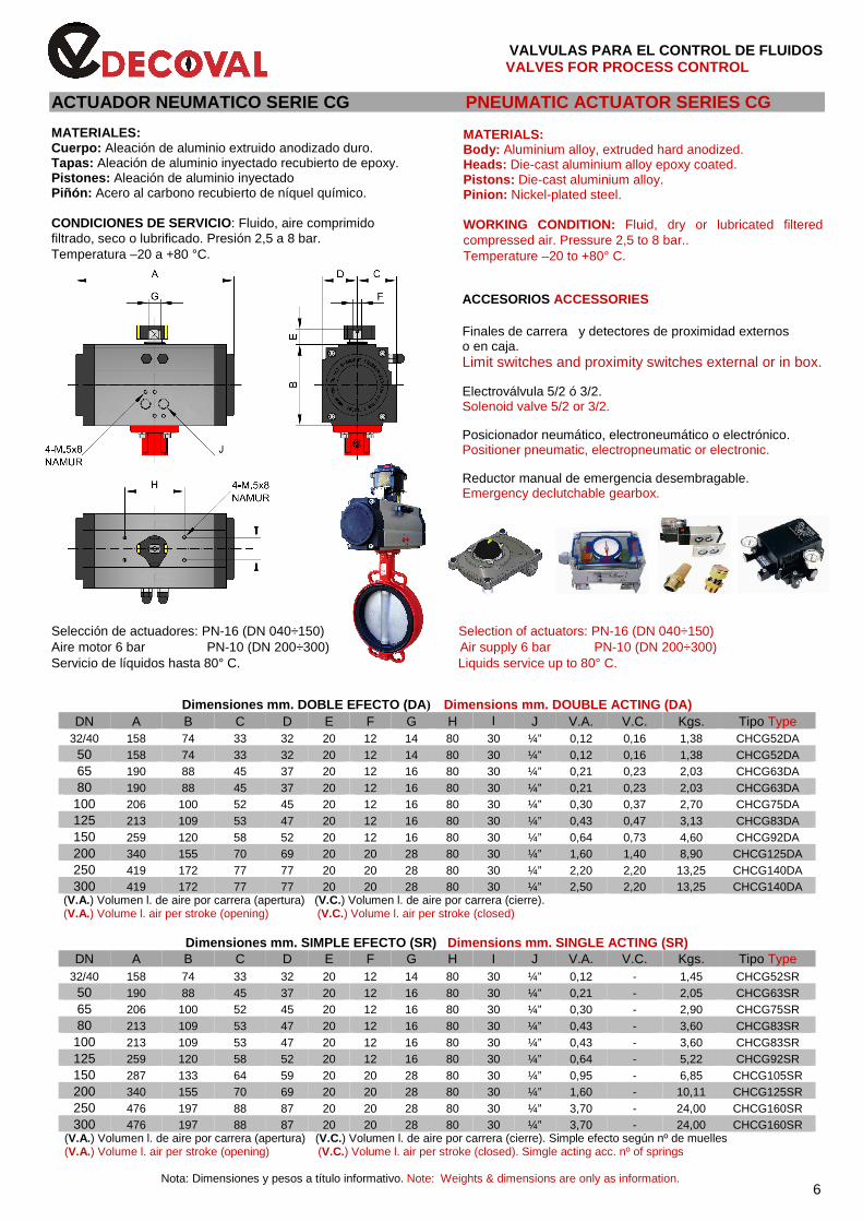
ACTUADOR NEUMATICO SERIE CG PNEUMATIC ACTUATOR SERIES CG MATERIALES: Cuerpo: Aleación de aluminio extruido anodizado duro. Tapas: Aleación de aluminio inyectado recubierto de epoxy. Pistones: Aleación de aluminio inyectado Piñón: Acero al carbono recubierto de níquel químico. CONDICIONES DE SERVICIO: Fluido, aire comprimido filtrado, seco o lubrificado. Presión 2,5 a 8 bar. Temperatura –20 a +80 °C.
MATERIALS: Body: Aluminium alloy, extruded hard anodized. Heads: Die-cast aluminium alloy epoxy coated. Pistons: Die-cast aluminium alloy. Pinion: Nickel-plated steel. WORKING CONDITION: Fluid, dry or lubricated filtered compressed air. Pressure 2,5 to 8 bar.. Temperature –20 to +80° C.
ACCESORIOS ACCESSORIES
Finales de carrera y detectores de proximidad externos o en caja. Limit switches and proximity switches external or in box.
Electroválvula 5/2 ó 3/2. Solenoid valve 5/2 or 3/2. Posicionador neumático, electroneumático o electrónico. Positioner pneumatic, electropneumatic or electronic. Reductor manual de emergencia desembragable. Emergency declutchable gearbox. Selección de actuadores: PN-16 (DN 040÷150) Selection of actuators: PN-16 (DN 040÷150) Aire motor 6 bar PN-10 (DN 200÷300) Air supply 6 bar PN-10 (DN 200÷300) Servicio de líquidos hasta 80° C. Liquids service up to 80° C.
Dimensiones mm. DOBLE EFECTO (DA ) Dimensions mm. DOUBLE ACTING (DA) DN A B C D E F G H I J V.A. V.C. Kgs. Tipo Type
32/40 158 74 33 32 20 12 14 80 30 ¼” 0,12 0,16 1,38 CHCG52DA 50 158 74 33 32 20 12 14 80 30 ¼” 0,12 0,16 1,38 CHCG52DA 65 190 88 45 37 20 12 16 80 30 ¼” 0,21 0,23 2,03 CHCG63DA 80 190 88 45 37 20 12 16 80 30 ¼” 0,21 0,23 2,03 CHCG63DA
100 206 100 52 45 20 12 16 80 30 ¼” 0,30 0,37 2,70 CHCG75DA 125 213 109 53 47 20 12 16 80 30 ¼” 0,43 0,47 3,13 CHCG83DA 150 259 120 58 52 20 12 16 80 30 ¼” 0,64 0,73 4,60 CHCG92DA 200 340 155 70 69 20 20 28 80 30 ¼” 1,60 1,40 8,90 CHCG125DA 250 419 172 77 77 20 20 28 80 30 ¼” 2,20 2,20 13,25 CHCG140DA 300 419 172 77 77 20 20 28 80 30 ¼” 2,50 2,20 13,25 CHCG140DA
(V.A.) Volumen l. de aire por carrera (apertura) (V.C.) Volumen l. de aire por carrera (cierre). (V.A.) Volume l. air per stroke (opening) (V.C.) Volume l. air per stroke (closed)
Dimensiones mm. SIMPLE EFECTO (SR) Dimensions mm. SINGLE ACTING (SR) DN A B C D E F G H I J V.A. V.C. Kgs. Tipo Type
32/40 158 74 33 32 20 12 14 80 30 ¼” 0,12 - 1,45 CHCG52SR 50 190 88 45 37 20 12 16 80 30 ¼” 0,21 - 2,05 CHCG63SR 65 206 100 52 45 20 12 16 80 30 ¼” 0,30 - 2,90 CHCG75SR 80 213 109 53 47 20 12 16 80 30 ¼” 0,43 - 3,60 CHCG83SR
100 213 109 53 47 20 12 16 80 30 ¼” 0,43 - 3,60 CHCG83SR 125 259 120 58 52 20 12 16 80 30 ¼” 0,64 - 5,22 CHCG92SR 150 287 133 64 59 20 20 28 80 30 ¼” 0,95 - 6,85 CHCG105SR 200 340 155 70 69 20 20 28 80 30 ¼” 1,60 - 10,11 CHCG125SR 250 476 197 88 87 20 20 28 80 30 ¼” 3,70 - 24,00 CHCG160SR 300 476 197 88 87 20 20 28 80 30 ¼” 3,70 - 24,00 CHCG160SR
(V.A.) Volumen l. de aire por carrera (apertura) (V.C.) Volumen l. de aire por carrera (cierre). Simple efecto según nº de muelles (V.A.) Volume l. air per stroke (opening) (V.C.) Volume l. air per stroke (closed). Simgle acting acc. nº of springs
Nota: Dimensiones y pesos a título informativo. Note: Weights & dimensions are only as information. 6
VALVULAS PARA EL CONTROL DE FLUIDOS VALVES FOR PROCESS CONTROL
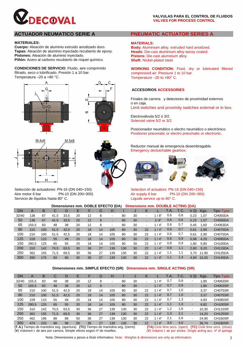
ACTUADOR NEUMATICO SERIE A PNEUMATIC ACTUATOR SERIES A MATERIALES: Cuerpo: Aleación de aluminio extruido anodizado duro. Tapas: Aleación de aluminio inyectado recubierto de epoxy. Pistones: Aleación de aluminio inyectado. Piñón: Acero al carbono recubierto de níquel químico. CONDICIONES DE SERVICIO: Fluido, aire comprimido filtrado, seco o lubrificado. Presión 1 a 10 bar. Temperatura –20 a +80 °C.
MATERIALS: Body: Aluminium alloy, extruded hard anodized. Heads: Die-cast aluminium alloy epoxy coated. Pistons: Die-cast aluminium alloy. Shaft: Nickel-plated steel. WORKING CONDITION: Fluid, dry or lubricated filtered compressed air. Pressure 1 to 10 bar. Temperature –20 to +80° C.
ACCESORIOS ACCESSORIES
Finales de carrera y detectores de proximidad externos o en caja. Limit switches and proximity switches external or in box.
Electroválvula 5/2 ó 3/2. Solenoid valve 5/2 or 3/2.
Posicionador neumático o electro neumático o electrónico. Positioner pneumatic or electro pneumatic or electronic. Reductor manual de emergencia desembragable. Emergency declutchable gearbox. Selección de actuadores: PN-16 (DN 040÷150) Selection of actuators: PN-16 (DN 040÷150) Aire motor 6 bar PN-10 (DN 200÷300) Air supply 6 bar PN-10 (DN 200÷300) Servicio de líquidos hasta 80° C. Liquids service up to 80° C.
Dimensiones mm. DOBLE EFECTO (DA ) Dimensions mm. DOUBLE ACTING (DA) DN A B C D E F G H I J K L T.A. T.C. V (l) Kgs. Tipo Type
32/40 138 67 41,5 33,5 20 12 8 - 80 30 - 1 / 8” 0,6 0,6 0,23 1,07 CH050DA 50 138 67 41.5 33,5 20 12 8 - 80 30 - 1/ 8” 0,6 0,6 0.23 1,07 CH050DA 65 155,5 83 48 38 20 12 8 - 80 30 - 1 / 4” 0,6 0,7 0,45 1,60 CH063DA 80 210 100 51,5 42,5 20 18 14 105 80 30 22 1 / 4” 0,6 0,7 0,61 2,90 CH075DA
100 210 100 51,5 42,5 20 18 14 105 80 30 22 1 / 4” 0,6 0,7 0,61 2,90 CH075DA 125 228 110 55 49 20 18 14 105 80 30 22 1 / 4” 0,6 0,9 0,98 4,20 CH085DA 150 280,5 125 65 55 20 18 14 105 80 30 22 1 / 4” 0,8 0,9 1,80 5,80 CH100DA 200 310 142 70,5 63,5 30 36 27 139 130 30 22 1 / 4” 0.8 1,1 2,80 9,20 CH115DA 250 362 155 71,5 69,5 30 36 27 139 130 30 22 1 / 4” 1,1 1,1 3,70 11,90 CH125DA 300 390 175 83 80 30 36 27 139 130 30 22 1 / 4” 1,1 1,4 4,90 15,50 CH145DA
Dimensiones mm. SIMPLE EFECTO (SR) Dimensions mm. SINGLE ACTING (SR)
DN A B C D E F G H I J K L T.A. T.C. V (l) Kgs. Tipo Type 32/40 155,5 83 48 38 20 12 8 - 80 30 - 1 / 4” 0,7 0,9 - 1,80 CH063SR
50 155,5 83 48 38 20 12 8 - 80 30 - 1 / 4” 0,7 0,9 - 1,80 CH063SR 65 210 100 51,5 42,5 20 18 14 105 80 30 22 1 / 4” 0,7 1,0 - 3,37 CH075SR 80 210 100 51,5 42,5 20 18 14 105 80 30 22 1 / 4” 0,7 1,0 - 3,37 CH075SR
100 228 110 55 49 20 18 14 105 80 30 22 1 / 4” 0,7 1,3 - 4,83 CH085SR 125 280,5 125 65 55 20 18 14 105 80 30 22 1 / 4” 1,1 1,3 - 6,82 CH100SR 150 310 142 70,5 63,5 30 36 27 139 130 30 22 1 / 4” 1,2 1,6 - 10,30 CH115SR 200 362 155 71,5 69,5 30 36 27 139 130 30 22 1 / 4” 1,3 2,1 - 14,20 CH125SR 250 462 196 88 88 50 36 27 139 130 30 22 1 / 4” 2,1 2,6 - 24,90 CH160SR 300 474 220 98 98 50 36 27 139 130 30 22 1 / 4” 3,5 4,0 - 36,74 CH180SR
(T.A.) Tiempo de maniobra seg. (apertura) (TC) Tiempo de maniobra seg. (cierre) (TA) Cicle time secs. (open) (TC) Cicle time secs. (close) (V) Volumen l. de aire por carrera. Simple efecto según nº de muelles. (V) Volume l. air per stroke. Single acting acc. nº of springs
Nota: Dimensiones y pesos a título informativo. Note: Weights & dimensions are only as information. 7
VALVULAS PARA EL CONTROL DE FLUIDOS
VALVES FOR PROCESS CONTROL
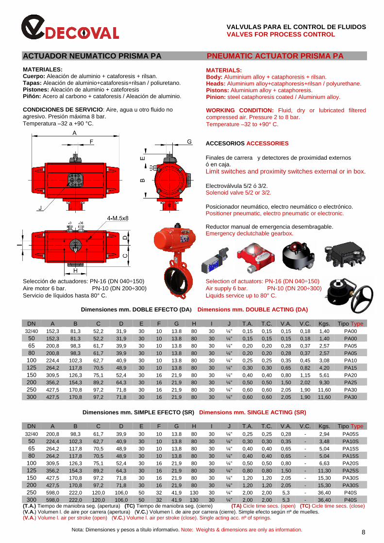
ACTUADOR NEUMATICO PRISMA PA PNEUMATIC ACTUATOR PRISMA PA MATERIALES: Cuerpo: Aleación de aluminio + cataforesis + rilsan. Tapas: Aleación de aluminio+cataforesis+rilsan / poliuretano. Pistones: Aleación de aluminio + cateforesis Piñón: Acero al carbono + cataforesis / Aleación de aluminio. CONDICIONES DE SERVICIO: Aire, agua u otro fluido no agresivo. Presión máxima 8 bar. Temperatura –32 a +90 °C.
MATERIALS: Body: Aluminium alloy + cataphoresis + rilsan. Heads: Aluminium alloy+cataphoresis+rilsan / polyurethane. Pistons: Aluminium alloy + cataphoresis. Pinion: steel cataphoresis coated / Aluminium alloy. WORKING CONDITION: Fluid, dry or lubricated filtered compressed air. Pressure 2 to 8 bar. Temperature –32 to +90° C.
ACCESORIOS ACCESSORIES
Finales de carrera y detectores de proximidad externos ó en caja. Limit switches and proximity switches external or in box.
Electroválvula 5/2 ó 3/2. Solenoid valve 5/2 or 3/2. Posicionador neumático, electro neumático o electrónico. Positioner pneumatic, electro pneumatic or electronic. Reductor manual de emergencia desembragable. Emergency declutchable gearbox. Selección de actuadores: PN-16 (DN 040÷150) Selection of actuators: PN-16 (DN 040÷150) Aire motor 6 bar. PN-10 (DN 200÷300) Air supply 6 bar. PN-10 (DN 200÷300) Servicio de líquidos hasta 80° C. Liquids service up to 80° C.
Dimensiones mm. DOBLE EFECTO (DA ) Dimensions mm. DOUBLE ACTING (DA)
DN A B C D E F G H I J T.A. T.C. V.A. V.C. Kgs. Tipo Type 32/40 152,3 81,3 52,2 31,9 30 10 13.8 80 30 ¼” 0,15 0,15 0,15 0,18 1,40 PA00
50 152,3 81,3 52,2 31,9 30 10 13.8 80 30 ¼” 0,15 0,15 0,15 0,18 1,40 PA00 65 200,8 98,3 61,7 39,9 30 10 13.8 80 30 ¼” 0,20 0,20 0,28 0,37 2,57 PA05 80 200,8 98,3 61,7 39,9 30 10 13.8 80 30 ¼” 0,20 0,20 0,28 0,37 2,57 PA05
100 224,4 102,3 62,7 40,9 30 10 13.8 80 30 ¼” 0,25 0,25 0,35 0,45 3,08 PA10 125 264,2 117,8 70,5 48,9 30 10 13.8 80 30 ¼” 0,30 0,30 0,65 0,82 4,20 PA15 150 309,5 126,3 75,1 52,4 30 16 21,9 80 30 ¼” 0,40 0,40 0,80 1,15 5,61 PA20 200 356,2 154,3 89,2 64,3 30 16 21,9 80 30 ¼” 0,50 0,50 1,50 2,02 9,30 PA25 250 427,5 170,8 97,2 71,8 30 16 21,9 80 30 ¼” 0,60 0,60 2,05 1,90 11,60 PA30 300 427,5 170,8 97,2 71,8 30 16 21,9 80 30 ¼” 0,60 0,60 2,05 1,90 11,60 PA30
Dimensiones mm. SIMPLE EFECTO (SR) Dimensions mm. SINGLE ACTING (SR)
DN A B C D E F G H I J T.A. T.C. V.A. V.C. Kgs. Tipo Type 32/40 200,8 98,3 61,7 39,9 30 10 13.8 80 30 ¼” 0,25 0,25 0,28 - 2,94 PA05S
50 224,4 102,3 62,7 40,9 30 10 13.8 80 30 ¼” 0,30 0,30 0,35 - 3,48 PA10S 65 264,2 117,8 70,5 48,9 30 10 13,8 80 30 ¼” 0,40 0,40 0,65 - 5,04 PA15S 80 264,2 117,8 70,5 48,9 30 10 13,8 80 30 ¼” 0,40 0,40 0,65 - 5,04 PA15S
100 309,5 126,3 75,1 52,4 30 16 21,9 80 30 ¼” 0,50 0,50 0,80 - 6,63 PA20S 125 356,2 154,3 89,2 64,3 30 16 21,9 80 30 ¼” 0,80 0,80 1,50 - 11,30 PA25S 150 427,5 170,8 97,2 71,8 30 16 21,9 80 30 ¼” 1,20 1,20 2,05 - 15,30 PA30S 200 427,5 170,8 97,2 71,8 30 16 21,9 80 30 ¼” 1,20 1,20 2,05 - 15,30 PA30S 250 598,0 222,0 120,0 106,0 50 32 41,9 130 30 ¼” 2,00 2,00 5,3 - 36,40 P40S 300 598,0 222,0 120,0 106,0 50 32 41,9 130 30 ¼” 2,00 2,00 5,3 - 36,40 P40S
(T.A.) Tiempo de maniobra seg. (apertura) (TC) Tiempo de maniobra seg. (cierre) (TA) Cicle time secs. (open) (TC) Cicle time secs. (close) (V.A.) Volumen l. de aire por carrera (apertura) (V.C.) Volumen l. de aire por carrera (cierre). Simple efecto según nº de muelles. (V.A.) Volume l. air per stroke (open) (V.C.) Volume l. air per stroke (close). Single acting acc. nº of springs.
Nota: Dimensiones y pesos a título informativo. Note: Weights & dimensions are only as information. 8
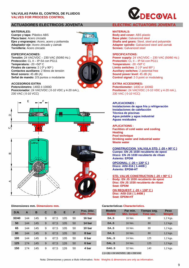
VALVULAS PARA EL CONTROL DE FLUIDOS VALVES FOR PROCESS CONTROL ACTUADORES ELECTRICOS JOVENTA ELECTRIC ACTUATORS JOVENTA MATERIALES: MATERIALS: Cuerpo y tapa: Plástico ABS Body and cover: ABS plastic Placa base: Acero zinzado Base plate: Galvanized steel Ejes y engranajes: Acero, acero y poliamida Shafts and gears: Steel, steel and polyamide Adaptador eje: Acero zincado y zamak Adapter spindle: Galvanized steel and zamak Tornillería: Acero zincado Screws: Galvanized steel ESPECIFICACIONES: SPECIFICATIONS: Tensión: 24 VAC/VDC – 230 VAC (50/60 Hz.) Power supply: 24 VAC/VDC – 230 VAC (50/60 Hz.) Protección: CL II – IP-54 con PG11 Protectión: CL II – IP-54 con PG11 Temperatura: -20 +50º C Temperature: -20 +50º C Finales de carrera: 2 ( 0º y 90º ) Limits switches : 2 ( 0º and 90º ) Contactos auxiliares: 2 libres de tensión Auxiliary switches: 2 potential free Nivel sonoro: 45 dB (A) Sound power level: 45 dB (A) Señal de mando: 2/3 puntos o modulante Control signal: 2-3 point or modulating
ACCESORIOS EXTRA EXTRA ACCESORIES: Potenciómetro: 140Ω ó 1000Ω Potentiometer: 140Ω or 1000Ω Posicionador: 24 VAC/VDC ( 0-10 VDC y 4-20 mA.), Positioner: 24 VAC/VDC ( 0-10 VDC y 4-20 mA.), 230 VAC ( 0-10 VCC) 230 VAC ( 0-10 VCC)
APLICACIONES : Instalaciones de agua fria y refrigeración Instalaciones de calefacción Técnica de piscinas Agua potable y agua industrial Aguas residuales APLICATIONS : Facilities of cold water and cooling Heating Pool technique Drinking water and industrial water Waste water CONSTRUCCION VALVULA STD. ( -20 + 90º C ) Cuerpo: EN JS 1030 recubierto de epoxi Disco: EN JS 1030 recubierto de rilsan Asiento: EPDM
OPCIONAL: ( -20 + 130º C ) Disco: AISI-316 ( 1.4408 ) Asiento: EPDM-HT STD. VALVE CONSTRUCTION ( -20 + 90º C ) Body: EN JS 1030 recubierto de epoxi Disc: EN JS 1030 recubierto de rilsan Seat: EPDM
ON REQUEST: ( -20 + 130º C ) Disc: AISI-316 ( 1.4408 ) Seat: EPDM-HT Dimensiones mm. Dimensions mm. Características Characteristics.
D.N. A B C D E F Pres. Difer. Difer. Press.
Modelo Model
Par min. Min. torque
Tiempo seg. Time sec.
Peso Weight
32/40 144 145 9 67,5 105 50 16 bar DA..S 16 Nm. 80 1,2 Kgs.
50 144 145 9 67,5 105 50 14 bar DA..S 16 Nm. 80 1,2 kgs.
65 144 145 9 67,5 105 50 10 bar DA..S 16 Nm. 80 1,2 kgs.
80 144 145 9 67,5 105 50 8 bar DA..S 16 Nm. 80 1,2 kgs.
100 144 145 9 67,5 105 50 6 bar DAL..S 24 Nm. 125 1,2 kgs.
125 174 145 9 67,5 126 50 6 bar DAL..S 24 Nm. 125 1,2 kgs.
150 174 145 9 67,5 126 50 4 bar DAG..S 32 Nm. 140 1,2 kgs.
(..) = (1) = 24 VAC/VDC, (2) = 230 VAC
Nota: Dimensiones y pesos a título informativo. Note: Weights & dimensions are only as information.
9

VALVULAS PARA EL CONTROL DE FLUIDOS VALVES FOR PROCESS CONTROL ACTUADORES ELECTRICOS J+J ELECTRIC ACTUATORS J+J MATERIALES: MATERIALS: Cuerpo y tapas: Poliamida anticorrosiva. Enclosure: Anticorrosive polyamide. Levas internas: Poliamida y fibra de vidrio. Internal cams: Glass filled polyamide Ejes principales externos: Acero inoxidable Main external shaft; Stainless steel Engranajes: Acero y poliamida Gears: Steel and polyamide Indicador de posición: Poliamida+fibra de vidrio Position indicador: Glass filled polyamide Tornillería exterior: Acero inoxidable Fastening: Stainless steel ESPECIFICACIONES: SPECIFICATIONS: Tiempo bajo tension: 75% Duty rating: 75% Protección: IP-67 IP rating IEC 60529: IP-67 Temperatura: -20 +70º C Temperature: -20 +70ª C Finales de carrera: 4 SPDT Limits switches: 4 SPDT Resistencia calefactora: 3,5 W Heater: 3,5 W Conectores: DIN 43650, ISO 440 y C192 Plugs: DIN 43650, ISO 440 & C192 ACCESORIOS EXTRA: EXTRA ACCESORIES: Posicionador digital DPS-2005 (4-20 mA. 0-10V.). Digital positioner DPS-2005 (4-20 mA. 0-10V.). Retorno por baterias sistema BSR. BSR emergency battery back system.
J3C-L/H20 J3C-L/H35 J3C-L/H55 J3C-L/H85 J2C-L/H140 J2C-L/H300 Selección de actuadores: PN-16 (DN-040÷150) Selection of actuators: PN-16 (DN-040÷150) PN-10 (DN-200÷250) PN-10 (DN-200÷250) PN-6 (DN-300) PN-6 (DN-300) Servicio de líquidos hasta 80°C. Liquids service up to 80 C. Dimensiones mm. Dimensions mm. Características Characteristics.
DN
A
B
C
D
E
Modelo Model
Voltaje Voltage
Par máximo Maximum Torque
Tiempo seg Time sec.
Peso Kgs Weight
40 171 110 126 51 - J3C-L/H20
L =
12
- 24
VA
C /
VD
C
H -
85
- 24
0 V
AC
/ V
DC
-0
/ +
5 %
20 Nm máximo 25 Nm 10 1,8 50 65 171 110 126 51 - J3C-L/H35 35 Nm máximo 38 Nm 10 1,9
80 196 110 126 51 - J3C-L/H55 55 Nm máximo 60 Nm 14 2,4
100 125 196 110 126 51 18,2 J3C-L/H85 85 Nm máximo 90 Nm 30 3,0
150 254 214 128 107 - J2C-L/H140 140 Nm máximo 170 Nm 33 5,2
200 254 214 128 107 - J2C-L/H300 300 Nm máximo 380 Nm 60 5,2
250 254 214 128 107 - J2C-L/H300 300 Nm máximo. 380 Nm 60 5,2 300 254 214 128 107 - J2C-L/H300 300 Nm máximo 380 Nm 60 5,2
Nota: Dimensiones y pesos a título informativo. Note: Weights & dimensions are only as information. 10
VALVULAS PARA EL CONTROL DE FLUIDOS VALVES FOR PROCESS CONTROL
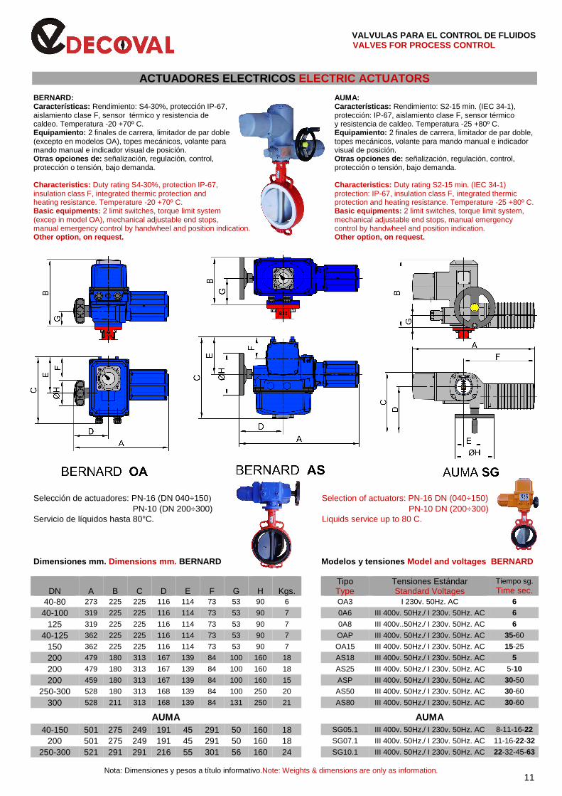
ACTUADORES ELECTRICOS ELECTRIC ACTUATORS BERNARD: AUMA: Características: Rendimiento: S4-30%, protección IP-67, Características: Rendimiento: S2-15 min. (IEC 34-1), aislamiento clase F, sensor térmico y resistencia de protección: IP-67, aislamiento clase F, sensor térmico caldeo. Temperatura -20 +70º C. y resistencia de caldeo. Temperatura -25 +80º C. Equipamiento: 2 finales de carrera, limitador de par doble Equipamiento: 2 finales de carrera, limitador de par doble, (excepto en modelos OA), topes mecánicos, volante para topes mecánicos, volante para mando manual e indicador mando manual e indicador visual de posición. visual de posición. Otras opciones de: señalización, regulación, control, Otras opciones de: señalización, regulación, control, protección o tensión, bajo demanda. protección o tensión, bajo demanda. Characteristics: Duty rating S4-30%, protection IP-67, Characteristics: Duty rating S2-15 min. (IEC 34-1) insulation class F, integrated thermic protection and protection: IP-67, insulation class F, integrated thermic heating resistance. Temperature -20 +70º C. protection and heating resistance. Temperature -25 +80º C. Basic equipments: 2 limit switches, torque limit system Basic equipments: 2 limit switches, torque limit system, (excep in model OA), mechanical adjustable end stops, mechanical adjustable end stops, manual emergency manual emergency control by handwheel and position indication. control by handwheel and position indication. Other option, on request. Other option, on re quest.
Selección de actuadores: PN-16 (DN 040÷150) Selection of actuators: PN-16 DN (040÷150) PN-10 (DN 200÷300) PN-10 DN (200÷300) Servicio de líquidos hasta 80°C. Liquids service up to 80 C. Dimensiones mm. Dimensions mm. BERNARD Modelos y tensiones Model and voltages BERNARD
DN
A
B
C
D
E
F
G
H
Kgs.
Tipo Type
Tensiones Estándar Standard Voltages
Tiempo sg. Time sec.
40-80 273 225 225 116 114 73 53 90 6 OA3 I 230v. 50Hz. AC 6
40-100 319 225 225 116 114 73 53 90 7 0A6 III 400v. 50Hz./ I 230v. 50Hz. AC 6
125 319 225 225 116 114 73 53 90 7 0A8 III 400v..50Hz./ I 230v. 50Hz. AC 6
40-125 362 225 225 116 114 73 53 90 7 OAP III 400v. 50Hz./ I 230v. 50Hz. AC 35-60
150 362 225 225 116 114 73 53 90 7 OA15 III 400v. 50Hz./ I 230v. 50Hz. AC 15-25
200 479 180 313 167 139 84 100 160 18 AS18 III 400v. 50Hz./ I 230v. 50Hz. AC 5
200 479 180 313 167 139 84 100 160 18 AS25 III 400v. 50Hz./ I 230v. 50Hz. AC 5-10
200 459 180 313 167 139 84 100 160 15 ASP III 400v. 50Hz./ I 230v. 50Hz. AC 30-50
250-300 528 180 313 168 139 84 100 250 20 AS50 III 400v. 50Hz./ I 230v. 50Hz. AC 30-60
300 528 211 313 168 139 84 131 250 21 AS80 III 400v. 50Hz./ I 230v. 50Hz. AC 30-60
AUMA
AUMA
40-150 501 275 249 191 45 291 50 160 18 SG05.1 III 400v. 50Hz./ I 230v. 50Hz. AC 8-11-16-22
200 501 275 249 191 45 291 50 160 18 SG07.1 III 400v. 50Hz./ I 230v. 50Hz. AC 11-16-22-32
250-300 521 291 291 216 55 301 56 160 24 SG10.1 III 400v. 50Hz./ I 230v. 50Hz. AC 22-32-45-63
Nota: Dimensiones y pesos a título informativo.Note: Weights & dimensions are only as information.
11
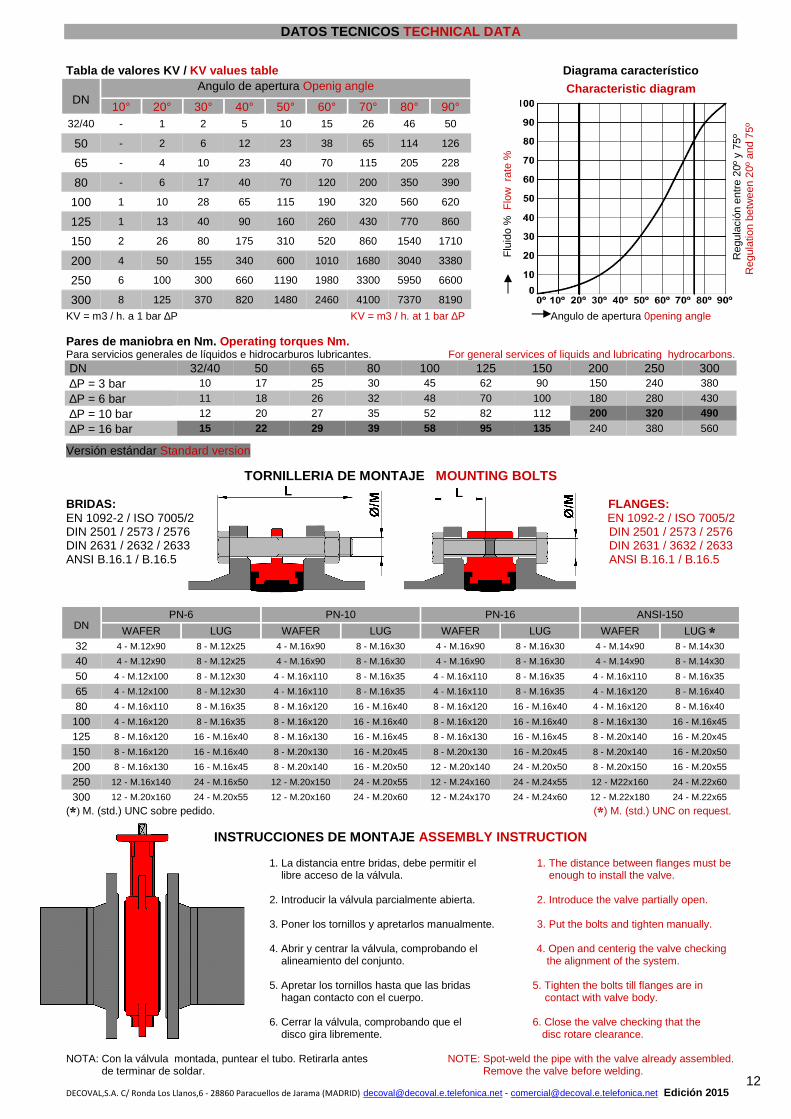
DATOS TECNICOS TECHNICAL DATA
Tabla de valores KV / KV values table Diagrama característico
DN Angulo de apertura Openig angle
Characteristic diagram
Reg
ulac
ión
entr
e 20
º y
75º
R
egul
atio
n be
twee
n 20
º an
d 75
º
10° 20° 30° 40° 50° 60° 70° 80° 90°
F
luid
o %
Flo
w r
ate
%
32/40 - 1 2 5 10 15 26 46 50
50 - 2 6 12 23 38 65 114 126
65 - 4 10 23 40 70 115 205 228
80 - 6 17 40 70 120 200 350 390
100 1 10 28 65 115 190 320 560 620
125 1 13 40 90 160 260 430 770 860
150 2 26 80 175 310 520 860 1540 1710
200 4 50 155 340 600 1010 1680 3040 3380
250 6 100 300 660 1190 1980 3300 5950 6600
300 8 125 370 820 1480 2460 4100 7370 8190
KV = m3 / h. a 1 bar ∆P KV = m3 / h. at 1 bar ∆P Angulo de apertura 0pening angle Pares de maniobra en Nm. Operating torques Nm. Para servicios generales de líquidos e hidrocarburos lubricantes. For general services of liquids and lubricating hydrocarbons. DN 32/40 50 65 80 100 125 150 200 250 300 ∆P = 3 bar 10 17 25 30 45 62 90 150 240 380
∆P = 6 bar 11 18 26 32 48 70 100 180 280 430
∆P = 10 bar 12 20 27 35 52 82 112 200 320 490
∆P = 16 bar 15 22 29 39 58 95 135 240 380 560
Versión estándar Standard version
TORNILLERIA DE MONTAJE MOUNTING BOLTS BRIDAS: FLANGES: EN 1092-2 / ISO 7005/2 EN 1092-2 / ISO 7005/2 DIN 2501 / 2573 / 2576 DIN 2501 / 2573 / 2576 DIN 2631 / 2632 / 2633 DIN 2631 / 3632 / 2633 ANSI B.16.1 / B.16.5 ANSI B.16.1 / B.16.5
DN
PN-6 PN-10 PN-16 ANSI-150
WAFER LUG WAFER LUG WAFER LUG WAFER LUG * 32 4 - M.12x90 8 - M.12x25 4 - M.16x90 8 - M.16x30 4 - M.16x90 8 - M.16x30 4 - M.14x90 8 - M.14x30
40 4 - M.12x90 8 - M.12x25 4 - M.16x90 8 - M.16x30 4 - M.16x90 8 - M.16x30 4 - M.14x90 8 - M.14x30
50 4 - M.12x100 8 - M.12x30 4 - M.16x110 8 - M.16x35 4 - M.16x110 8 - M.16x35 4 - M.16x110 8 - M.16x35
65 4 - M.12x100 8 - M.12x30 4 - M.16x110 8 - M.16x35 4 - M.16x110 8 - M.16x35 4 - M.16x120 8 - M.16x40
80 4 - M.16x110 8 - M.16x35 8 - M.16x120 16 - M.16x40 8 - M.16x120 16 - M.16x40 4 - M.16x120 8 - M.16x40
100 4 - M.16x120 8 - M.16x35 8 - M.16x120 16 - M.16x40 8 - M.16x120 16 - M.16x40 8 - M.16x130 16 - M.16x45
125 8 - M.16x120 16 - M.16x40 8 - M.16x130 16 - M.16x45 8 - M.16x130 16 - M.16x45 8 - M.20x140 16 - M.20x45
150 8 - M.16x120 16 - M.16x40 8 - M.20x130 16 - M.20x45 8 - M.20x130 16 - M.20x45 8 - M.20x140 16 - M.20x50
200 8 - M.16x130 16 - M.16x45 8 - M.20x140 16 - M.20x50 12 - M.20x140 24 - M.20x50 8 - M.20x150 16 - M.20x55
250 12 - M.16x140 24 - M.16x50 12 - M.20x150 24 - M.20x55 12 - M.24x160 24 - M.24x55 12 - M22x160 24 - M.22x60
300 12 - M.20x160 24 - M.20x55 12 - M.20x160 24 - M.20x60 12 - M.24x170 24 - M.24x60 12 - M.22x180 24 - M.22x65
(*) M. (std.) UNC sobre pedido. (*) M. (std.) UNC on request.
INSTRUCCIONES DE MONTAJE ASSEMBLY INSTRUCTION 1. La distancia entre bridas, debe permitir el 1. The distance between flanges must be libre acceso de la válvula. enough to install the valve. 2. Introducir la válvula parcialmente abierta. 2. Introduce the valve partially open. 3. Poner los tornillos y apretarlos manualmente. 3. Put the bolts and tighten manually. 4. Abrir y centrar la válvula, comprobando el 4. Open and centerig the valve checking alineamiento del conjunto. the alignment of the system. 5. Apretar los tornillos hasta que las bridas 5. Tighten the bolts till flanges are in hagan contacto con el cuerpo. contact with valve body. 6. Cerrar la válvula, comprobando que el 6. Close the valve checking that the disco gira libremente. disc rotare clearance.
NOTA: Con la válvula montada, puntear el tubo. Retirarla antes NOTE: Spot-weld the pipe with the valve already assembled. de terminar de soldar. Remove the valve before welding.
DECOVAL,S.A. C/ Ronda Los Llanos,6 - 28860 Paracuellos de Jarama (MADRID) [email protected] - [email protected] Edición 2015 12