ug-34 conexion
DESCRIPTION
Paper TecnicoTRANSCRIPT

ASME BPVC 2008a Section VIII - Division 1 General Requirement UG-34RULES FOR UNSTAYED FLAT HEADS AND COVERS Calculation 1
HC Flat Head: ASTM B462 Gr.10276 GAPN F2157-S6 Bolting: ASTM A193 B8M Bolt Size 1-1/8"-7 UNC-2AER Gasket: Elastomer below 75A Process Connection
ANSI Raised Face Standard (125-250 Ra)6250 (psi) Internal Design Pressure Size ANSI 1-1/2"
Rating 2500#-20 to 100 (ºF) Ambient (atmospheric)-20 to 100 (ºF) Process (operating)
Bolt Loads Analysis Flat Heads and Covers AnalysisOperating Condition
Gasket Seating Condition
NOTATIONAb = cross-sectional area of the bolts using root diameter of the thread, or least diameterAb = 2.851 (in^2) For bolting thread size 1-1/8"-7 UNC-2AAm = total required cross-sectional area of bolts, taken as the greater of Am1 and Am2Am = 1.5138 (in^2)
b = effective gasket or joint-contact-surface seating widthb = 0.08875 (in)C = a factor depending upon the method of attachment of headC = 0.3 for FIG. UG-34 (j)d = diameter, or short span, measured as indicated in Fig. UG-34d = 2.2375 (in)E = joint efficiency, from Table UW-12, Fig L-1.4-2E = 1G = diameter at location of gasket load reactionG = 2.2375 (in)
Except as noted in sketchWhen b0 </= 1/4 in (6mm)
InputMaterial
Pressure
Temperature
FF Product Information
Output
AcceptableAcceptable
Acceptable
FIG. UG-34 (j)
FIG. UG-34 (j)

G = mean diameter of gasket contact faceG = 2.2375 (in)
When b0 > 1/4 in (6mm)G = outside diameter of gasket contact face less 2bG = 2.2375 (in)
H = total hydrostatic end forceH = 0.785*G^2*P
Hp = total joint-contact surface compression loadHp = 2*b*3.14*G*m*PhG = gasket moment arm, equal to the radial distance from the centerline of the bolts
to the line of the gasket reaction, as shown in Table 2-5.2hG = 1.75625 (in)m = gasket factor, obtain from Table 2-1.1 [note 1, 2-5(c)(1)]m = 0.50y = gasket or joint-contact-surface unit seating load, [Note 1, 2-5(c)]y = 0 (psi)P = internal design pressure (UG-21)P = 6250 (psi)
Sa = allowable bolt stress at atmospheric temperature (UG-23)Sf = allowable design stress for material of flange at design or atmospheric temperature
t = thickness of flat head or covert = 2.15 (in)
W = total bolt load given for circular heads for Formulas (3) and (4), 2-5(e)Wm1 = minimum required bolt load for operating conditions.Wm2 = minimum required bolt load for gasket seating conditions.
CALCULATIONOperating Condition Gasket Seating Condition
2-5(c)(1) Wm1 = H + Hp 2-5(c)(2) Wm2 = 3.14*b*G*yWm1 = 0.785*G^2*P+(2*b*3.14*G*m*P) = 3.14x0.08875x2.2375x0
= 0.785x2.2375^2x6250+(2x0.08875x3.14x2.2375x0.5x6250Wm2 = 0.0 (lbf)
2-5(e)(3) W = Wm1 2-5(e)(4) W = (Am + Ab)Sa/2W = 28459.7 (lbf) = (1.5138+2.8514)x18800/2
W = 41032.8 (lbf)Sec II Part D
Table 3 Allowable Bolt Stress at Process Temperature at Atmospheric TemperatureSb = 18800 (psi) Sa = 18800 (psi)
2-5(d) Am1 = Wm1/Sb 2-5(d) Am2 = Wm2/Sa = 28459.7/18800 = 0/18800
Am1 = 1.51381 (in^2) Am2 = 0 (in^2)
2-5(d) Am = Greater of Am1 and Am2Am = 1.51380 (in^2) 2-5(d) Ab shall not be less than Am
Sec II Part D Table 1 Allowable Design Stress at Process Temperature at Atmospheric Temperature
Sf = 27300 (psi) Sf = 27300 (psi)UG-34 (c)(2)
The minimum require thickness of flat unstayed circular heads,t_min = d*sqrt(C*P/(S*E)+1.9*W*hg/(S*E*d^3))
Operating t_min = 2.2375xSQRT(0.3x6250/(27300x1)+1.9x28459.7x1.75625/(27300x1x2.2375^3))Gasket Seating t_min = 2.2375xSQRT(0.3x6250/(27300x1)+1.9x41032.8x1.75625/(27300x1x2.2375^3))
Operating Condition Gasket Seating Conditiont_min = 1.378 (in) t_min = 1.608 (in)
AcceptableAcceptable
Table 2-5.2

ASME BPVC 2008a Section VIII - Division 1 Mandatory Appendix 2RULES FOR BOLTED FLANGE CONNECTIONS WITH RING TYPE GASKETS
Bolting Analysis4.75 (in) "A" Outside Diameter1.1 (in) "t" Thickness Flange Moments & Stress4 No. Bolts Operating
0.622 "B" Inside Diameter Gasket Seating3.25 (in) "C" Bolt-circle Diameter Flange Rigidity1.38 (in) "D" Gasket Area OD Operating
Process Size & Rating Gasket Seating
HC Flange ASTM B462 Gr.10276S6 Bolt ASTM A193 B8M Bolt Size 3/4"-10 UNC-2AER Gasket Elastomer below 75A Process Connection
ANSI Raised Face Standard (125-250 Ra)3750 (psi) Design Pressure Size ANSI 1/2"
Rating 1500#
-20 to 100 (ºF) Ambient (atmospheric)-20 to 100 (ºF) Process (operating)
2-5 Bolt Loads
Wm1 = H + Hp Wm2 = 3.14*b*G*y(lb) = 0.785*G^2*P+(2b*3.14*G*m*P) Wm2 = 0 lb
W = Wm1 W = (Am + Ab)Sa/2W = 5183.234 lb W = 14279 lb
Sb = 18.8 ksi Sa = 18.8 ksiAm1 = Wm1/Sb Am2 = Wm2/SaAm1 = 0.275704 in^2 Am2 = 0 in^2Am = Greater of Am1 and Am2Am = 0.275704 in^2 Ab = 1.243338 in^2
2-5 (d) Total Required and Actual Bolt AreasAb will not be less than Am
TEST
2-6 Flange Moments
M0 = MD + MT + MG M0 = W(C-G)/2 = (HDhD)+(HThT)+(HGhG) M0 = 16056.73 in*lb
ANSI 1/2" 1500#
Acceptable
Acceptable
Temperature
Acceptable
AcceptableAcceptable
Material
Pressure
Input OutputFlange
Operating Condition Gasket Seating Condition
Acceptable
Gasket Seating ConditionOperating Condition

M0 = 6215.935 in*lb
2-7 Calculation of Flange StressesMoment Arms for Flange Loads under Operation Conditions
hD = (C - B) / 2hD = 1.314 inhT = (hD + hG) / 2 Effective Gasket WidthhT = 1.21925 in N = 0.379hG = (C - G) / 2 b0 = N/2hG = 1.1245 in b0 = 0.1895
H = 0.785*(G^2)*PH = 2949.64 lb
HD = 0.785*(B^2)*P HT = H-HDHD = 1138.89 lb HT = 1810.751 lb
HG = W-H HG = W-HHG = 2233.594 lb HG = 11329.35 lb
Factors Y = 1/(K-1)*(0.66845+5.71690*(K^2*log(K,10))/(K^2-1)Y = 0.874534Z = (K^2+1)/(K^2-1)Z = 1.034893K = A/BK = 7.636656
With Hub
Not Applicable
Longitudinal hub stressSH = f*M0/(L*g1^2B)
Radial flange stressSR = (1.33te + 1)M0/(L*t^2B)
Tangential flange stressST = Y*M0/(t^2B) - Z*SR
Without HubCalculate without considering the hub
ST = Y*M0/(t^2*B) ST = Y*M0/(t^2*B)ST = 7222.828 psi ST = 18657.69 psiSR = 0 SR = 0SH = 0 SH = 0
2-8 Allowable Flange Design Stresses
(a) (1) Sf = 27.3 ksi Sf = 27.3 ksiLongitudinal hub stress SHFor cast iron Not Applicable
SH </= SfOther than cast iron
SH </= 1.5*SfNot Applicable
For optional type flanges designed as integralSH </= min[1.5*Sf, 1.5*Sn]
For integral type flanges with hub welded to the neck, pipe or vessel wallSH </= min[1.5*Sf, 2.5*Sn]
(a) (2)Radial flange stress SR
Operating Condition Gasket Seating Condition
Gasket Seating ConditionOperating Condition
Gasket Seating ConditionOperating Condition

SR </= Sf(a) (3)
Tangential flange stressST </= Sf ST </= Sf
(a) (4)(SH+SR)/2 </= Sf
(SH+ST)/2 </= Sf(SH+ST)/2 = 3611 psi (SH+ST)/2 = 9329 psi
(c)Shearing stress Not Applicable
Ss </= 0.8*Snshearing stress shall be calculated on the basis of Wm1 or Wm2 whichever is greater
2-9 Split Loose FlangesNot Applicable
When the flange consists of a single split flange or flange ringit shall be designed as if it were a solid flange,
Using 200% of the total moment M0 as defined
When the flange consists of two split rings each ringit shall be designed as if it were a solid flange
Using 75% of the total moment M0 as defined
The splits should preferably be midway between bolt holes
2-11 Flanges Subject to External PressuresNot Applicable
Total Moment for operating conditionsM0 = HD(hD-hG)+HT(hT-hG)
Total Moment for gasket seatingM0 = W*hG
Where Pe = external design pressureH = 0.785*G^2*Pe
HT = H - HDHD = 0.785B^2*PeW = (Am2+Ab)/2*Sa
2-12 Flanges with Nut-stopsNot Applicable
2-13 Reverse FlangesNot Applicable
2-14 Flange Rigidity
E = Modulus of elasticity for the flange materialE = 29.8 x 10^6 PSIE = 29800000 PSI
KL = Rigidity factor for loose-type flangesKL = 0.2
J = Rigidity indexJ = 109.4*M0/(E*t^3*KL*(LN(K)))
Flange Rigidity J </= 1.0
M0 = 6215.935 in*lb M0 = 16056.73 in*lbGasket Seating ConditionOperating Condition
AcceptableAcceptable
Acceptable Acceptable

J = 0.042167 J = 0.108923
2-3 NotationH = total hydrostatic end force (0.785G^2*P)
Hp = total joint-contact surface compression load (2b x 3.14G*m*P)G = diameter at location of gasket load reactionG = 1.001 in
Except as noted in sketch1.001 When b0 </= 1/4 in (6mm)
G = mean diameter of gasket contact face1.001 When b0 > 1/4 in (6mm)
G = outside diameter of gasket contact face less 2bP = internal design pressureP = 3750 psi
For flanges subject to external design pressureb = effective gasket or joint-contact-surface seating widthb = 0.1895 inm = gasket factor, table 2-5.1m = 0.5y = gasket or joint-contact-surface unit seating load.y = 0 psi
Am = total required cross-sectional area of bolts, taken as the greater of Am1 and Am2Am1 = total cross-sectional area of bolts at root of thread, Wm1/SbAm2 = total cross-sectional area of bolts at root of thread, Wm2/Sa
Ab = cross-sectional area of the bolts using the root diameter of the thread or least diameter of unthreaded positionSa = allowable bolt stress at atmospheric temperature (lookup table)Sb = allowable bolt stress at design temperature (lookup table)M0 = total moment acting upon the flange, for the operating conditions or gasket seating as may applyW = flange design bolt load, for the operating condition or gasket seating, as my applyC = bolt-circle diameterN = width used to determine the basic gasket seating with b0N = 0.379 in
b0 = basic gasket seting widthb0 = 0.1895 inA = outside diameter of flange or, where slotted holes extend to the outside of the flange
the diameter to the bottom of the slotsB = inside diameter of flange.
When B is less than 20g1,it will be optional for the designer to substitute B1 for B in the formula for longitudinal stress SH
hD = radial distance from the bolt circle, to the circle on which HD actshT = radial distance from the bolt circle, to the circle on which HT actshG = radial distance from the bolt circle, to the circle on which HG actsHD = hydrostatic end force on area inside of flange (0.785*B^2P)HT = difference between total hydrostatic end force and the hydrostatic end force on area inside of flange (H-HD)HG = gasket load (difference between flange design bolt load and total hydrostatic end force W-H)
f = hub stress correction factor for integral flanges = 1 (minimum) = 1 for hubs of uniform thickness (g1 / g0 = 1) = 1 for loose hubbed flanges
L = factor = (t*e+1)/T+t^3/dt = flange thicknesst = 1.1 ine = factor = F/h0 for integral type flanges = FL/h0 for loose type flanges
Sf = allowable design stress for material of flangeat design temperature for operating conditionat atmospheric temperature for gasket seating
Sn = allowable design stress for material of nozzle neck, vessel or pipe wallat design temperature for operating conditionat atmospheric temperature for gasket seating
AcceptableAcceptable

ASME BPVC 2008a Section VIII - Division 1 General Requirement UG-27RULES FOR THICKNESS OF SHELLS UNDER INTERNAL PRESSURE Calculation 3
AVAILABLE MATERIALCODE
S6 316L SST A479 Gr. S31603HC ALLOY C-276 B574 Gr. N10276SD DUPLEX 2205 A479 Gr. S31803
BPVC Sec II Part D Table 1. Max Allowable Stress (S) at Temperature ºF (ksi)Material \ Temperature -20 to 100 200 300 400 500 600
316L SST A479 Gr. S31603 16.7 16.7 16.7 15.7 14.8 14.0ALLOY C-276 B574 Gr. N10276 27.3 24.9 23.0 21.3 19.9 18.7DUPLEX 2205 A479 Gr. S31803 25.7 25.7 24.8 23.9 23.3 23.1
AVAILABLE SIZE & DIMENSIONSIZE "OD" (in) "ID" (in) "t" (in) "R" (in)
3/4" ANSI 2.62 0.82 0.90 0.411" ANSI 2.62 1.05 0.79 0.53
1-1/2" ANSI 2.88 1.61 0.64 0.812" ANSI 3.62 2.00 0.81 1.003" ANSI 5.00 2.00 1.50 1.00
NOTATIONE = joint efficiency, from Table UW-12, Fig L-1.4-2E = 1.00P = internal design pressure (UG-21)R = inside radius of the shell course under considerationS = maximum allowable stress valuet = thickness of shell
FORMULAS OF CALCULATIONUG-27 (c) Cylindrical Shells
UG-27 (c) (1) Circumferential Stress (Longitudinal Joints)minimum required thickness tmin_C
tmin_C = P*R/(S*E-0.6*P)or P_C = S*E*t/(R+0.6*t)
UG-27 (c) (2) Longitudinal Stress (Circumferential Joints)minimum required thickness tmin_L
tmin_L = P*R/(2*S*E+0.4*P)or P_L = 2*S*E*t/(R-0.4*t)
RESULTS OF CALCULATION 3For 3/4" ANSI t = 0.90 (in)
R = 0.41 (in)UG-27 (c) (1) Circumferential Stress P_C = Sx1x0.9/(0.41+0.6x0.9)
Temperature / Circumferential Allowable Pressure (P_C) at Temperature ºF (ksi)Materials Pressure -20 to 100 200 300 400 500 600
316L SST A479 Gr. S31603 15.8 15.8 15.8 14.9 14.0 13.3ALLOY C-276 B574 Gr. N10276 25.9 23.6 21.8 20.2 18.9 17.7DUPLEX 2205 A479 Gr. S31803 24.3 24.3 23.5 22.6 22.1 21.9
UG-27 (c) (2) Longitudinal Stress P_L = 2xSx1x0.9/(0.41-0.4x0.9)
DESCRIPTION
PROPERTIES OF CALIBRATION RING

Temperature / Longitudinal Allowable Pressure (P_L) at Temperature ºF (ksi)Materials Pressure -20 to 100 200 300 400 500 600
316L SST A479 Gr. S31603 601.2 601.2 601.2 565.2 532.8 504.0ALLOY C-276 B574 Gr. N10276 982.8 896.4 828.0 766.8 716.4 673.2DUPLEX 2205 A479 Gr. S31803 925.2 925.2 892.8 860.4 838.8 831.6
For 1" ANSI t = 0.79 (in)R = 0.53 (in)
UG-27 (c) (1) Circumferential Stress P_C = Sx1x0.785/(0.525+0.6x0.785)Temperature / Circumferential Allowable Pressure (P_C) at Temperature ºF (ksi)
Materials Pressure -20 to 100 200 300 400 500 600316L SST A479 Gr. S31603 13.2 13.2 13.2 12.4 11.7 11.0
ALLOY C-276 B574 Gr. N10276 21.5 19.6 18.1 16.8 15.7 14.7DUPLEX 2205 A479 Gr. S31803 20.3 20.3 19.5 18.8 18.4 18.2
UG-27 (c) (2) Longitudinal Stress P_L = 2xSx1x0.785/(0.525-0.4x0.785)Temperature / Longitudinal Allowable Pressure (P_L) at Temperature ºF (ksi)
Materials Pressure -20 to 100 200 300 400 500 600316L SST A479 Gr. S31603 124.3 124.3 124.3 116.8 110.1 104.2
ALLOY C-276 B574 Gr. N10276 203.1 185.3 171.1 158.5 148.1 139.1DUPLEX 2205 A479 Gr. S31803 191.2 191.2 184.5 177.8 173.4 171.9
For 1-1/2" ANSI t = 0.64 (in)R = 0.81 (in)
UG-27 (c) (1) Circumferential Stress P_C = Sx1x0.635/(0.805+0.6x0.635)Temperature / Circumferential Allowable Pressure (P_C) at Temperature ºF (ksi)
Materials Pressure -20 to 100 200 300 400 500 600316L SST A479 Gr. S31603 8.9 8.9 8.9 8.4 7.9 7.5
ALLOY C-276 B574 Gr. N10276 14.6 13.3 12.3 11.4 10.7 10.0DUPLEX 2205 A479 Gr. S31803 13.8 13.8 13.3 12.8 12.5 12.4
UG-27 (c) (2) Longitudinal Stress P_L = 2xSx1x0.635/(0.805-0.4x0.635)Temperature / Longitudinal Allowable Pressure (P_L) at Temperature ºF (ksi)
Materials Pressure -20 to 100 200 300 400 500 600316L SST A479 Gr. S31603 38.5 38.5 38.5 36.2 34.1 32.3
ALLOY C-276 B574 Gr. N10276 62.9 57.4 53.0 49.1 45.9 43.1DUPLEX 2205 A479 Gr. S31803 59.2 59.2 57.2 55.1 53.7 53.2
For 2" ANSI t = 0.81 (in)R = 1.00 (in)
UG-27 (c) (1) Circumferential Stress P_C = Sx1x0.81/(1+0.6x0.81)Temperature / Circumferential Allowable Pressure (P_C) at Temperature ºF (ksi)
Materials Pressure -20 to 100 200 300 400 500 600316L SST A479 Gr. S31603 9.1 9.1 9.1 8.6 8.1 7.6
ALLOY C-276 B574 Gr. N10276 14.9 13.6 12.5 11.6 10.8 10.2DUPLEX 2205 A479 Gr. S31803 14.0 14.0 13.5 13.0 12.7 12.6
UG-27 (c) (2) Longitudinal Stress P_L = 2xSx1x0.81/(1-0.4x0.81)Temperature / Longitudinal Allowable Pressure (P_L) at Temperature ºF (ksi)
Materials Pressure -20 to 100 200 300 400 500 600316L SST A479 Gr. S31603 40.0 40.0 40.0 37.6 35.5 33.6
ALLOY C-276 B574 Gr. N10276 65.4 59.7 55.1 51.0 47.7 44.8DUPLEX 2205 A479 Gr. S31803 61.6 61.6 59.4 57.3 55.8 55.4
For 3" ANSI t = 1.50 (in)R = 1.00 (in)
UG-27 (c) (1) Circumferential Stress P_C = Sx1x1.5/(1+0.6x1.5)Temperature / Circumferential Allowable Pressure (P_C) at Temperature ºF (ksi)
Materials Pressure -20 to 100 200 300 400 500 600316L SST A479 Gr. S31603 13.2 13.2 13.2 12.4 11.7 11.1
ALLOY C-276 B574 Gr. N10276 21.6 19.7 18.2 16.8 15.7 14.8DUPLEX 2205 A479 Gr. S31803 20.3 20.3 19.6 18.9 18.4 18.2
UG-27 (c) (2) Longitudinal Stress P_L = 2xSx1x1.5/(1-0.4x1.5)Temperature / Longitudinal Allowable Pressure (P_L) at Temperature ºF (ksi)
Materials Pressure -20 to 100 200 300 400 500 600316L SST A479 Gr. S31603 125.3 125.3 125.3 117.8 111.0 105.0
ALLOY C-276 B574 Gr. N10276 204.8 186.8 172.5 159.8 149.3 140.3DUPLEX 2205 A479 Gr. S31803 192.8 192.8 186.0 179.3 174.8 173.3
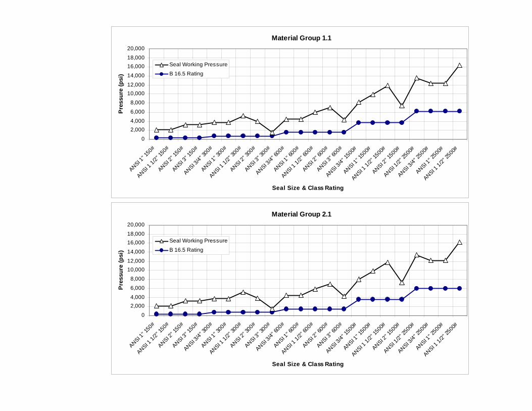
Material Group 1.1
0
2,0004,0006,000
8,00010,00012,000
14,00016,00018,000
20,000
ANSI 1" 1
50#
ANSI 1 1/
2" 15
0#ANSI 2
" 150
#ANSI 3
" 150#
ANSI 3/4" 3
00#
ANSI 1" 3
00#
ANSI 1 1/2"
300#
ANSI 2" 3
00#
ANSI 3" 3
00#
ANSI 3/4"
600#
ANSI 1" 6
00#
ANSI 1 1/
2" 60
0#ANSI 2
" 600
#ANSI 3
" 600#
ANSI 3/4" 1
500#
ANSI 1" 1
500#
ANSI 1 1/2"
1500
#
ANSI 2" 1
500#
ANSI 1/2"
2500
#
ANSI 3/4" 2
500#
ANSI 1" 2
500#
ANSI 1 1/
2" 25
00#
Seal Size & Class Rating
Pre
ssur
e (p
si)
Seal Working Pressure
B 16.5 Rating
Material Group 2.1
0
2,0004,0006,000
8,00010,00012,000
14,00016,00018,000
20,000
ANSI 1" 1
50#
ANSI 1 1/
2" 15
0#ANSI 2
" 150
#ANSI 3
" 150#
ANSI 3/4" 3
00#
ANSI 1" 3
00#
ANSI 1 1/2"
300#
ANSI 2" 3
00#
ANSI 3" 3
00#
ANSI 3/4"
600#
ANSI 1" 6
00#
ANSI 1 1/
2" 60
0#ANSI 2
" 600
#ANSI 3
" 600#
ANSI 3/4" 1
500#
ANSI 1" 1
500#
ANSI 1 1/2"
1500
#
ANSI 2" 1
500#
ANSI 1/2"
2500
#
ANSI 3/4" 2
500#
ANSI 1" 2
500#
ANSI 1 1/
2" 25
00#
Seal Size & Class Rating
Pre
ssur
e (p
si)
Seal Working Pressure
B 16.5 Rating

Material Group 2.2
02,0004,000
6,000
8,00010,00012,000
14,000
16,00018,000
20,000
ANSI 1" 1
50#
ANSI 1 1/
2" 15
0#ANSI 2
" 150#
ANSI 3" 1
50#
ANSI 3/4"
300#
ANSI 1" 3
00#
ANSI 1 1/
2" 30
0#ANSI 2
" 300#
ANSI 3" 3
00#
ANSI 3/4" 6
00#
ANSI 1" 6
00#
ANSI 1 1/
2" 60
0#ANSI 2
" 600
#ANSI 3
" 600
#
ANSI 3/4"
1500
#
ANSI 1" 1
500#
ANSI 1 1/
2" 15
00#
ANSI 2" 1
500#
ANSI 1/2"
2500
#
ANSI 3/4" 2
500#
ANSI 1" 2
500#
ANSI 1 1/
2" 25
00#
Seal Size & Class Rating
Pres
sure
(psi
)
Seal Working PressureB 16.5 Rating
Material Group 3.8
02,0004,000
6,000
8,00010,00012,000
14,000
16,00018,000
20,000
ANSI 1" 1
50#
ANSI 1 1/
2" 15
0#ANSI 2
" 150#
ANSI 3" 1
50#
ANSI 3/4"
300#
ANSI 1" 3
00#
ANSI 1 1/
2" 30
0#ANSI 2
" 300#
ANSI 3" 3
00#
ANSI 3/4" 6
00#
ANSI 1" 6
00#
ANSI 1 1/
2" 60
0#ANSI 2
" 600
#ANSI 3
" 600
#
ANSI 3/4"
1500
#
ANSI 1" 1
500#
ANSI 1 1/
2" 15
00#
ANSI 2" 1
500#
ANSI 1/2"
2500
#
ANSI 3/4" 2
500#
ANSI 1" 2
500#
ANSI 1 1/
2" 25
00#
Seal Size & Class Rating
Pres
sure
(psi
)
Seal Working PressureB 16.5 Rating
Figure 1. Maximum Working Pressure of F2 Seal upper for Temperature at 100°F

Material Group 1.1
0
1,000
2,000
3,000
4,000
5,000
6,000
7,000
8,000
ANSI 3/4" 150# ANSI 1/2" 150# ANSI 1/2" 300# ANSI 1/2" 600# ANSI 1/2" 1500#
Size & Class Rating
Pres
sure
(psi
)
B 16.5 RatingWorking Pressure
Material Group 2.1
0
1,000
2,000
3,000
4,000
5,000
6,000
7,000
8,000
ANSI 3/4" 150# ANSI 1/2" 150# ANSI 1/2" 300# ANSI 1/2" 600# ANSI 1/2" 1500#
Size & Class Rating
Pres
sure
(psi
)
B 16.5 RatingWorking Pressure
Material Group 2.2
0
1,000
2,000
3,000
4,000
5,000
6,000
7,000
8,000
ANSI 3/4" 150# ANSI 1/2" 150# ANSI 1/2" 300# ANSI 1/2" 600# ANSI 1/2" 1500#
Size & Class Rating
Pres
sure
(psi
)
B 16.5 RatingWorking Pressure
Material Group 3.8
0
2,000
4,000
6,000
8,000
10,000
12,000
14,000
ANSI 3/4" 150# ANSI 1/2" 150# ANSI 1/2" 300# ANSI 1/2" 600# ANSI 1/2" 1500#
Size & Class Rating
Pres
sure
(psi
)
B 16.5 RatingWorking Pressure
Figure 2. Maximum Working Pressure of F2 stud design Seal lower for Temperature at 100°F

Material Group 2.3
0
2,000
4,000
6,000
8,000
10,000
12,000
14,000
16,000
18,000
100 200 300 400 500 600
Process Temperature (ºF)
Wor
king
Pre
ssur
e (p
si)
B16.5 2500# Rating3/4" Calibration Ring1" Calibration Ring1-1/2" Calibration Ring2" Calibration Ring3" Calibration Ring
Material Group 2.8
0
5,000
10,000
15,000
20,000
25,000
30,000
100 200 300 400 500 600
Process Temperature (ºF)
Wor
king
Pre
ssur
e (p
si)
B16.5 2500# Rating3/4" Calibration Ring1" Calibration Ring1-1/2" Calibration Ring2" Calibration Ring3" Calibration Ring
Material Group 3.8
0
5,000
10,000
15,000
20,000
25,000
30,000
100 200 300 400 500 600
Process Temperature (ºF)
Wor
king
Pre
ssur
e (p
si)
B16.5 2500# Rating3/4" Calibration Ring1" Calibration Ring1-1/2" Calibration Ring2" Calibration Ring3" Calibration Ring
Figure 3. Maximum Working Pressure of F2 insert design Seal lower