tvp016210md - calidad telstar | inicio · es para encender el ventilador. empezará con baja...
TRANSCRIPT

1
STAND FANTVP016210MD
MANUAL DE INSTRUCCIONES
ABANICO DE PIE TVP016210MD
ABANICO DE PIETVP016210MD
2
PRECAUCIÓN
Lea las reglas e instrucciones cuidadosamente para un uso seguro
ADVERTENCIA
1. Este aparato tiene un enchufe polarizado (una hoja es más ancha que la otra. Para reducir el riesgo de
descarga eléctrica, este enchufe está diseñado para encajar en un toma corriente polarizado. Si el enchufe
no entra completamente, dele vuelta. Si todavía no encaja, póngase en contacto con un electricista.
2. Para reducir el riesgo de incendio o descarga eléctrica, no utilice este ventilador con ningún dispositivo
de control de velocidad sólido.
3. No deje el ventilador prendido si no hay nadie utilizándolo
REGLAS PARA UN USO SEGURO
1. Nunca inserte los dedos, lapiceros o cualquier otro objeto a través de la reja cuando el ventilador estén
encendido.
2. Desconecte el ventilador si lo piensa mover de lugar.
3. Desconecte el ventilador cuando retire las rejas para limpiarlas
4. Asegúrese de que el ventilador esté sobre una superficie estable o plana para evitar que se vuelque.
5. NO use el ventilador en una ventana. La lluvia puede crear daño eléctrico.
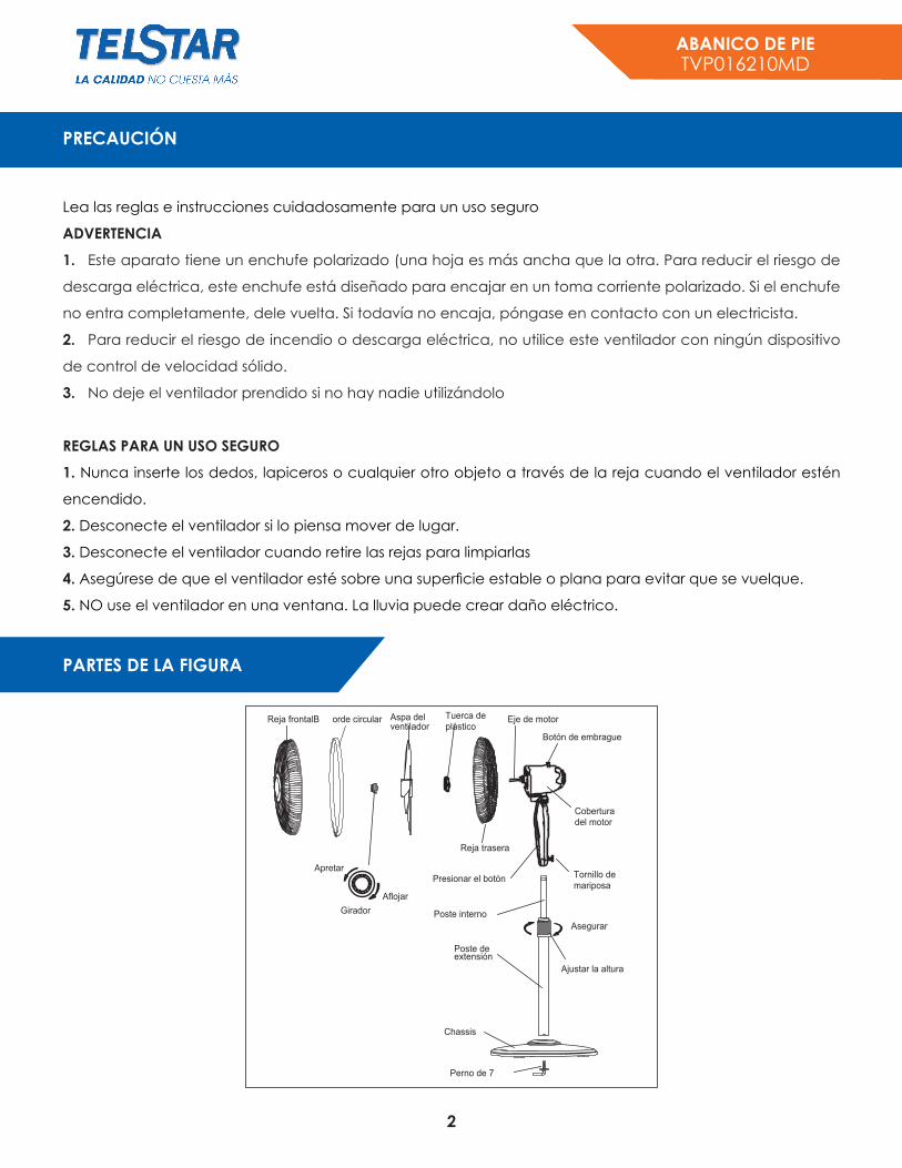
PARTES DE LA FIGURA
Perno de 7
Chassis
Poste deextensión
Poste interno
Aflojar
ApretarPresionar el botón
Girador
Reja trasera
Eje de motorTuerca deplástico
Aspa del ventilador
Reja frontalB orde circular
Botón de embrague
Cobertura del motor
Tornillo de mariposa
Asegurar
Ajustar la altura
ABANICO DE PIETVP016210MD
3
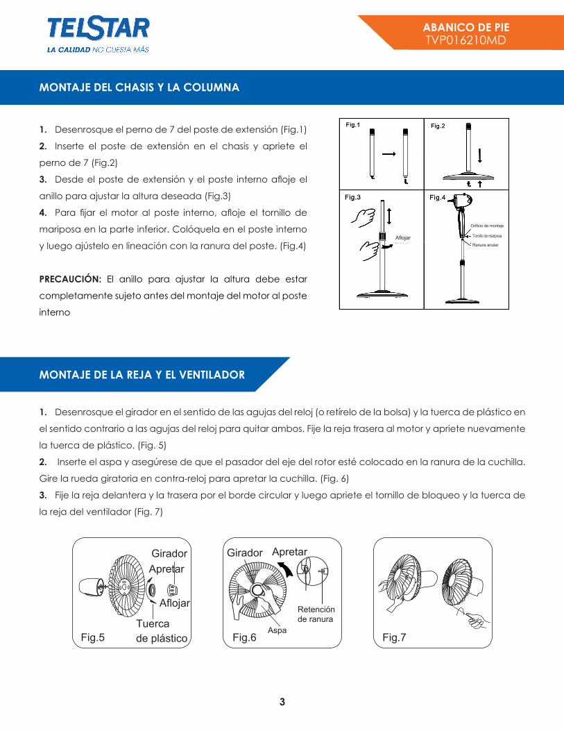
1. Desenrosque el perno de 7 del poste de extensión (Fig.1)
2. Inserte el poste de extensión en el chasis y apriete el
perno de 7 (Fig.2)
3. Desde el poste de extensión y el poste interno afloje el
anillo para ajustar la altura deseada (Fig.3)
4. Para fijar el motor al poste interno, afloje el tornillo de
mariposa en la parte inferior. Colóquela en el poste interno
y luego ajústelo en lineación con la ranura del poste. (Fig.4)
PRECAUCIÓN: El anillo para ajustar la altura debe estar
completamente sujeto antes del montaje del motor al poste
interno
1. Desenrosque el girador en el sentido de las agujas del reloj (o retírelo de la bolsa) y la tuerca de plástico en
el sentido contrario a las agujas del reloj para quitar ambos. Fije la reja trasera al motor y apriete nuevamente
la tuerca de plástico. (Fig. 5)
2. Inserte el aspa y asegúrese de que el pasador del eje del rotor esté colocado en la ranura de la cuchilla.
Gire la rueda giratoria en contra-reloj para apretar la cuchilla. (Fig. 6)
3. Fije la reja delantera y la trasera por el borde circular y luego apriete el tornillo de bloqueo y la tuerca de
la reja del ventilador (Fig. 7)
MONTAJE DEL CHASIS Y LA COLUMNA
MONTAJE DE LA REJA Y EL VENTILADOR
Aflojar
Orificio de montaje
Tornillo de mariposa
Ranura anular
Fig.5
Girador GiradorApretar
Apretar
Retenciónde ranura
Aspa
Aflojar
Tuerca
de plástico Fig.6 Fig.7

ABANICO DE PIETVP016210MD
4
I. Panel de control
Hay 2 teclas y 6 indicadores de luz. (Vea Fig.8)
1. “ ”
Es para encender el ventilador. Empezará con baja velocidad. Pulse de nuevo la tecla y el
ventilador funcionará con una velocidad media. Al pulsar por tercera vez, la velocidad será
máxima. A la cuarta vez, el ventilador se apagará.
2. “ ”
Se usa para temporizar el tiempo en el que va a estar funcionando el ventilador: una hora, dos
horas y cuatro horas. No presione la tecla del temporizador cuando vaya a usar el ventilador de
forma continua.
II. Control remoto
Hay 3 teclas. (See Fig.9)
3. “ ”
Después de que el ventilador haya comenzado, esta Tecla sirve para seleccionar la velocidad
del ventilador “bajo, medio, alto”
III. Control de variación
Para hacer que el ventilador varíe, presione el mando del embrague ubicado en la parte superior
de la estructura del motor. Para obtener el flujo de aire direccional, tire la perilla del embrague
hasta su posición inicial
IV. Ajuste de inclinación
Para ajustar el flujo de aire hacia arriba o hacia abajo, empuje la reja ligeramente a la dirección
deseada.
V. Ajuste de altura
La Altura del ventilador se puede ajustar aflojando el anillo de ajuste de altura levantando o
bajando cuidadosamente el ventilador, apretando firmemente el anillo.
INSTRUCCIONES DE USO
Fig.8
Fig.9
ABANICO DE PIETVP016210MD
5
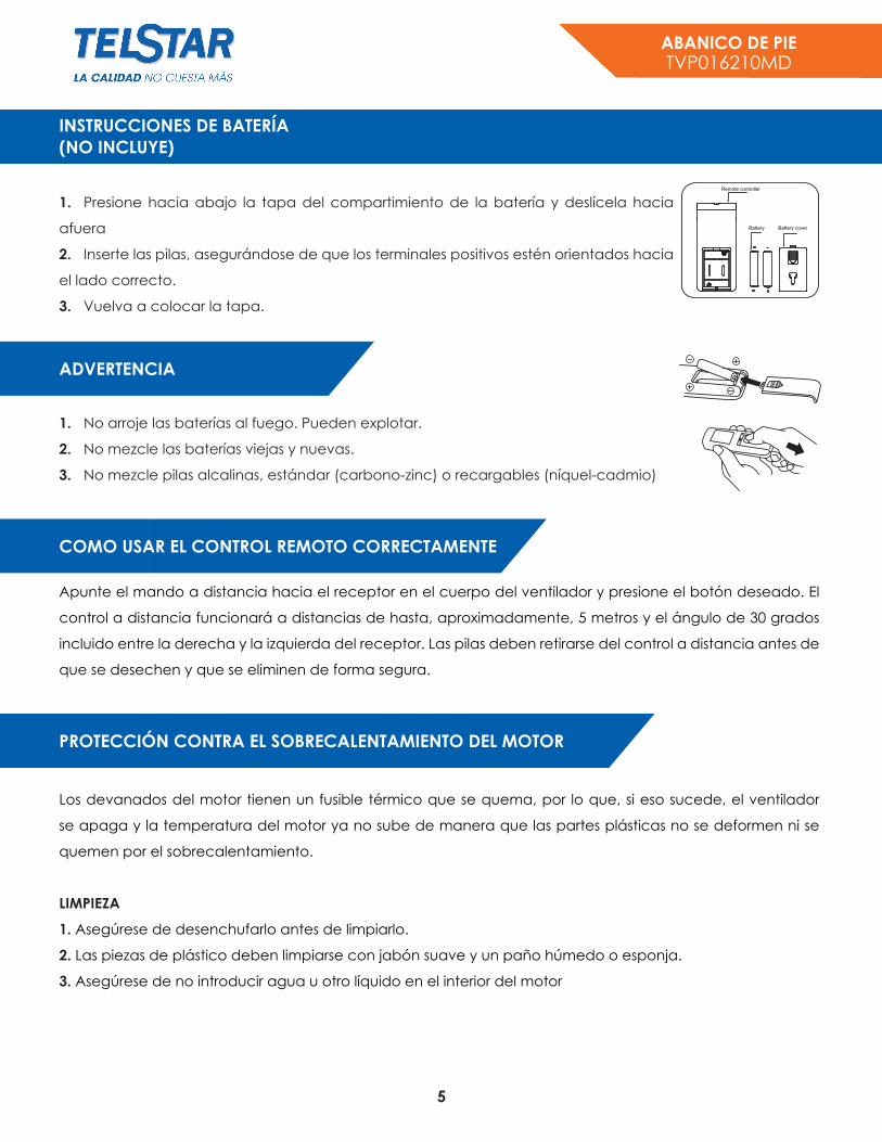
INSTRUCCIONES DE BATERÍA (NO INCLUYE)
1. Presione hacia abajo la tapa del compartimiento de la batería y deslícela hacia
afuera
2. Inserte las pilas, asegurándose de que los terminales positivos estén orientados hacia
el lado correcto.
3. Vuelva a colocar la tapa.
1. No arroje las baterías al fuego. Pueden explotar.
2. No mezcle las baterías viejas y nuevas.
3. No mezcle pilas alcalinas, estándar (carbono-zinc) o recargables (níquel-cadmio)
Apunte el mando a distancia hacia el receptor en el cuerpo del ventilador y presione el botón deseado. El
control a distancia funcionará a distancias de hasta, aproximadamente, 5 metros y el ángulo de 30 grados
incluido entre la derecha y la izquierda del receptor. Las pilas deben retirarse del control a distancia antes de
que se desechen y que se eliminen de forma segura.
Los devanados del motor tienen un fusible térmico que se quema, por lo que, si eso sucede, el ventilador
se apaga y la temperatura del motor ya no sube de manera que las partes plásticas no se deformen ni se
quemen por el sobrecalentamiento.
LIMPIEZA
1. Asegúrese de desenchufarlo antes de limpiarlo.
2. Las piezas de plástico deben limpiarse con jabón suave y un paño húmedo o esponja.
3. Asegúrese de no introducir agua u otro líquido en el interior del motor
ADVERTENCIA
COMO USAR EL CONTROL REMOTO CORRECTAMENTE
PROTECCIÓN CONTRA EL SOBRECALENTAMIENTO DEL MOTOR

6
STAND FANTVP016210MD
CAUTION
Read Rules for Safe Operation and Instructions Carefully
WARNING
1. This appliance has a polarized plug (one blade is wider than the other). To reduce the risk of electric shock,
this plug is intended to fit in a polarized outlet only one way. If plug does not fit fully in the outlet, reverse the
plug. If it still does not fit, contact a qualified electrician. Do not attempt to defeat this safely feature.
2. To reduce the risk of fire or electric shock, do not use this fan with any solid state speed control device.
3. Do not leave the fan running unattend.
RULES FOR SAFE OPERATION
1. Never insert fingers, pencils, or any other object through the grille when fan is running.
2. Disconnect fan when moving from one location to another.
3. Disconnect fan when removing grilles for cleaning.
4. Be sure fan is on a stable surface when operating to avoid overturning.
5. DO NOT use fan in window. Rain may create electrical hazard
PART FIGURE
7-shape Bolt
Chassis
Extension Pole
Internal Pole
Push button
Spinner
Rear grill
Motor shaftPlastic nutFan bladeFront grill CirclipClutch knob
Motor housing
Thumbscrew
Height AdjustmentRing

7
STAND FANTVP016210MD
1. Unscrew the 7-shape Bolt from the Extension Pole. (Fig.1)
2. Insert the extension pole into the chassis and tighten the
7-shape Bolt (Fig.2)
3. From the extension pole loosen the height adjustment
ring and adjust the internal pole to the desired height. (Note:
If you can’t find the internal pole, it must inside the extension
pole. You can pull it out from the extension pole.) (Fig.3)
4. To attach the head unit to the internal pole, loosen the
thumb screw on the bottom of the head unit. Place the
head unit on the internal pole and tighten the thumb screw
in alignment with the groove on the internal pole. (Fig.4)
CAUTION: Height adjustment ring must be fully fastened before the assembly of the motor section to the
internal pole.
1. Unscrew the spinner clockwise (or take the spinner out from the bag) and the plastic nut counterclockwise
to remove both of them. Fix the rear grill to the motor then tighten the plastic nut again. (Fig. 5)
2. Insert the blade into shaft, and make sure the rotor shaft pin is fitted into groove of the blade. Turn the spinner
counterclockwise to tighten the blade. (Fig. 6)
3. Fasten the front grill and the rear grill by the grill clip and then tighten the fan grill locking screw and nut.
(Fig. 7)
ASSEMBLY OF CHASSIS & COLUMN UNIT
GRILL & FAN BLADE ASSEMBLY
Fig.5
SpinnerTight
Loose
Plastic nutFig.6 Fig.7

8
STAND FANTVP016210MD
I. Control Panel
On the control panel, there are two keys and six indicator lights. (See Fig.8)
1. “ ” KEY
The key is for switching on the fan. The fan will be started at low speed.
Press the key again, the fan will work at middle speed.
Once again, it will work at the maximum speed. Once again, it will be switched off.
2. “ ” KEY
This key is touched repeatedly or in pressed state. The time to be set for one hour, two hours and four hours.
Do not press the timer key when the fan will be required to operate continuously. At the moment all timer led
don’t light.
II. Remote Control
On the remote control, there are three keys. (See Fig.9)
3. “ ” KEY
After the fan has started, this key serves as a speed selector in the sequence from “low-medium-
high-low” when this key being touched repeated or continuously.
III. Oscillation Control
To make the fan oscillate, press the clutch knob located on the top of the motor housing. To get the directional
airflow, pull the clutch knob up to its initial position.
IV. Tilt Adjustment
To adjust the air flow upward or downward, push the grilles lightly to the desired direction.
V. Height Adjustment
The height of the fan can be adjusted by loosening the height adjustment ring carefully raising or lowering the
fan and firmly re-tightening the height adjustment ring.
OPERATING INSTRUCTION
Fig.8
Fig.9

9
STAND FANTVP016210MD
BATTERIES INSTRUCTIONS (BATTERY NOT INCLUDED IN THE PACKING)
1. Press down on the battery compartment cover and slide it out.
2. Insert the batteries, making sure that the positive terminals are facing the proper way.
3. Replace the cover.
1. “Do not dispose of batteries in fire, batteries may explode or leak.”
2. Do not mix old and new batteries.
3. Do not mix alkaline, standard (carbon-zinc) or rechargeable (nickel-cadmium) batteries.
Point the remote controller at the receptor on body of the fan and press the desired button. The remote
controller will work at distances of up to roughly five meters and the angle of 30 degree included between
right and left from the receptor.
The batteries must be removed from the remote controller before it is scrapped and that they are disposed of
safely.
The windings of the motor have a thermal-fuse that burns out and the fan switches off and temperature of the
motor is no longer going up so that plastic parts of the fan don’t subject to deformation so far so to be burned
by the overheat if the motor is overheat for any unexpected reason.
CLEANING
1. Be sure to unplug from the electrical supply source before cleaning.
2. Plastic parts should be cleaned with mild soap and a damp cloth or sponge.
Thoroughly to remove soap film with clean water.
3. Be sure not to make water or other liquid enter inside of motor.
BATTERY WARNING AS BELOW
HOW TO USE THE REMOTE CONTROLLER CORRECTLY
OVERHEAT PROTECTION OF THE MOTOR

STAND FANTVP016210MD