the voice of the timber industry timber - minnesota forest
TRANSCRIPT
RoboCupRescue 2008 - Robot League Team P.A.N.D.O.R.A. (Greece)
Athanasiadis Ioannis1, Georgiou-Sarlikiotis Vasileios2, Zapartas Panagiotis3, Zolo-tas Christoforos4, Thomareis Nikitas5, Koufos Dimitrios6, Lamaris Konstantinos7,
Malliakas Panagiotis8, Papadopoulos Charalambos9, Papazoglou Anestis10, Skalistis Stefanos11, Simonidis Dimitrios12, Tsalidis Paraskevas13, Tselepis Nikolaos14, Feleki-
dis Nikolaos15, Foundas Zafiris16
1,2,3,4,5,6,7,8,9,10,12,13,14,15 Department of Electrical and Computer Engineering Aristotle University of Thessaloniki
Aristotle University Campus 541 24 Thessaloniki, Greece
www.ee.auth.gr
11,16Department of Computer and Math Science
Aristotle University of Thessaloniki Aristotle University Campus
541 24 Thessaloniki, Greece
[email protected] http://robotics.ee.auth.gr/
Abstract. This is the T.D.P. of the P.A.N.D.O.R.A. (Program for the Ad-vancement of Non Directed Operating Robotic Agents) Robotics Team of the Aristotle University of Thessaloniki to sign on for the RoboRescue competition of 2008. We are going to use one tracked platform, able to run on two modes, a fully autonomous and a fully manual one. The platform is equipped with a va-riety of sensors that will help it roam around the arenas, as well as locate the victims. The team has made great efforts to come up with the best result. Our platform is intended to be used for saving injured people trapped in a collapsed building during a natural disaster. The competition is an opportunity for us to evaluate the potential of our platform with more accuracy.
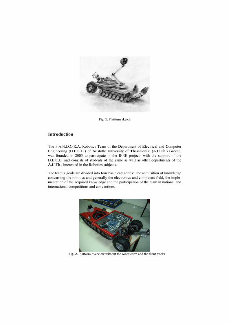
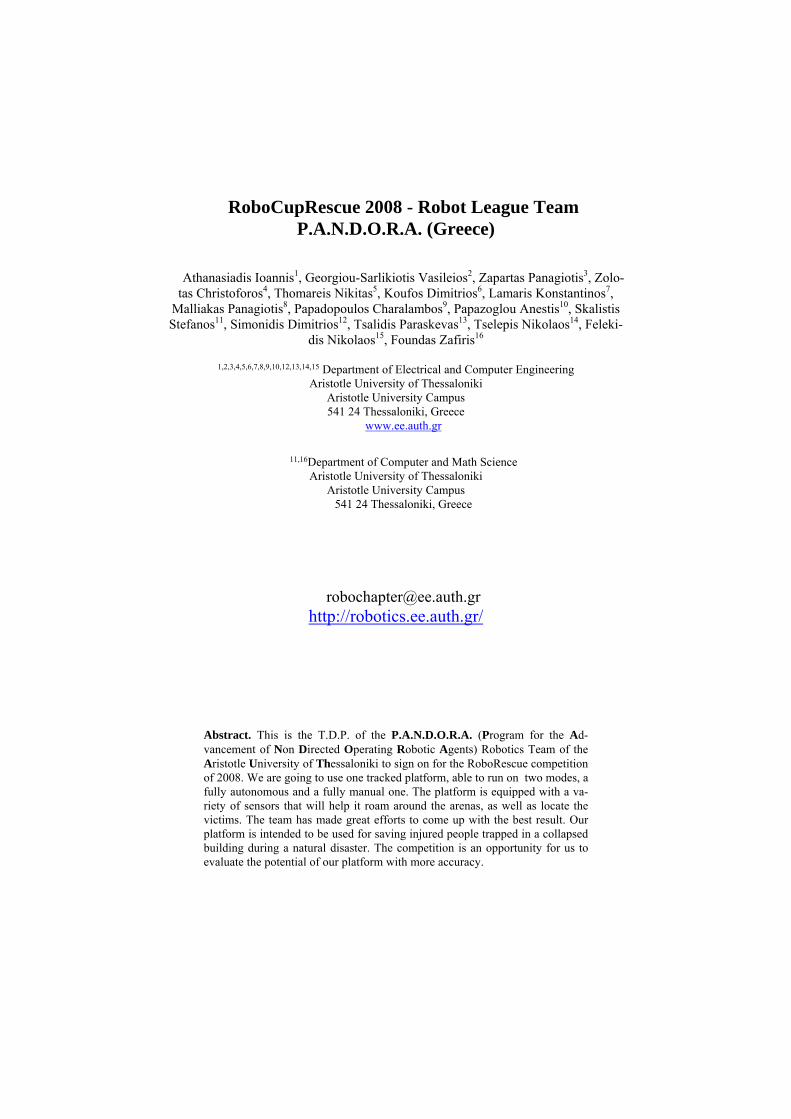
Fig. 1. Platform sketch
Introduction
The P.A.N.D.O.R.A. Robotics Team of the Department of Electrical and Computer Engineering (D.E.C.E.) of Aristotle University of Thessaloniki (A.U.Th.) Greece, was founded in 2005 to participate in the IEEE projects with the support of the D.E.C.E. and consists of students of the same as well as other departments of the A.U.Th., interested in the Robotics subjects.
The team’s goals are divided into four basic categories: The acquisition of knowledge concerning the robotics and generally the electronics and computers field, the imple-mentation of the acquired knowledge and the participation of the team in national and international competitions and conventions.
Fig. 2. Platform overview without the roboticarm and the front tracks

During the last year, the team was working on robotic arms. As a result, we devel-oped a robotic arm with four degrees of freedom and the ability of identification, grasp and carriage of a certain color and shape, object. Part of technical experience we acquired, is applied to the platform with which we are planning on participating in RoboRescue 2008. The team’s intention to participate in RoboRescue is a result of the team members’ belief concerning the utilization of robotic technology for humanitarian purposes. Having worked with technology in general and robotic technology in particular, we have realized that they have a great potential. So, working on the development of the platform we feel, not just like taking part in a competition, but that we are a part of a program that in the future might as well save human lives.
1. Team Members and Their Contributions
1. Athanasiadis Ioannis Artificial Intelligence 2. Georgiou-Sarlikiotis Vasileios Mechanical Parts Integration 3. Zapartas Panagiotis Sensors Integration 4. Zolotas Christoforos Programming Development 5. Thomareis Nikitas Artificial Intelligence 6. Koufos Dimitrios Electronics Integration 7. Lamaris Konstantinos Sound Processing 8. Malliakas Panagiotis Sound Processing 9. Papadopoulos Charalambos Project Management 10. Papazoglou Anestis Vision Processing 11. Skalistis Stefanos Artificial Intelligence 12. Simonidis Dimitrios Vision Processing 13. Tsalidis Paraskevas Artificial Intelligence 14. Tselepis Nikolaos Electronics Integration 15. Felekidis Nikolaos Sensors Integration 16. Foundas Zafiris Artificial Intelligence
2. Operator Station Set-up and Break-Down (10 minutes)
The team is going to get into the arena with two specially modified cases. The first one for the platform and the second one for the base station. The platform case con-tains the platform itself and a number of tools that we might need during the competi-tion. The second case, which is the base station case, contains the laptop, the Wi-Fi card of which, is on ad-hoc mode, an Omni antenna located on the top of the case, a backup battery and the remote control joystick. The number of operators are three. The head operator of the system, who carries the base station case and two backup operators who carry the platform case. The initialization procedure is implemented as follows:
• Transfer of all the objects in the area and development (3 minutes).

• Activation of the platform and the base station (3 minutes). • Communication check: so as to check the quality of our Wi-Fi con-
nection (1 minute). • Systems check: so as to verify that all the systems of the platform
work properly (1 minute).
Fig. 3. Base station case sketch
Fig. 4. Platform case sketch
3. Communications
We are going to use W-LAN 802.11a (5 GHz), following your suggestions and we are waiting for channel/band assignment on your behalf.

In case of communications loss, while the robot is on manual operating mode, the artificial intelligence is going to take control of the platform movement, until the communication is reestablished.
Rescue Robot League
P.A.N.D.O.R.A. (GREECE) Frequency Channel/Band Power (mW)
5.0 GHz - 802.11a 100
4. Control Method and Human-Robot Interface
The platform is able to run on two different modes. The first one is a fully autonom-ous mode, though giving the ability of interruption to the operator so as to make cor-rective movements. The second one involves a fully manual operation. The robot is controlled using a wired gamepad and the operator is able to hear the sounds that the robot receives from the arena, using a wired headset with three chan-nels of distinctive sound. The readings of the whole operation are shown on a Graph-ical User Interface. These are:
• Temperature reading • Camera shot distance reading • CO2 quantity readings • Distance readings of peripheral sensors • Platform inclination on x and y axis • Compass bearing • Mapping window • Robotic arm state • Battery level • Motors temperature • Wi-Fi signal power • Autonomous mode on/off • Manual mode on/off • Alert button • Sound source reading • Mode alternation button
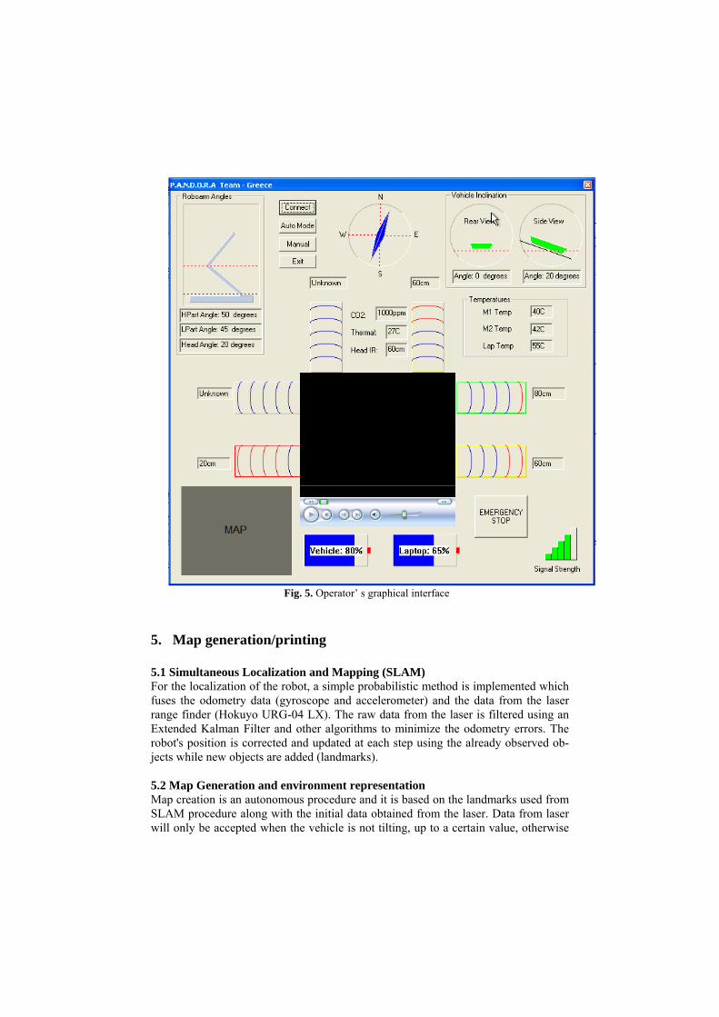
Fig. 5. Operator’ s graphical interface
5. Map generation/printing
5.1 Simultaneous Localization and Mapping (SLAM) For the localization of the robot, a simple probabilistic method is implemented which fuses the odometry data (gyroscope and accelerometer) and the data from the laser range finder (Hokuyo URG-04 LX). The raw data from the laser is filtered using an Extended Kalman Filter and other algorithms to minimize the odometry errors. The robot's position is corrected and updated at each step using the already observed ob-jects while new objects are added (landmarks).
5.2 Map Generation and environment representation Map creation is an autonomous procedure and it is based on the landmarks used from SLAM procedure along with the initial data obtained from the laser. Data from laser will only be accepted when the vehicle is not tilting, up to a certain value, otherwise
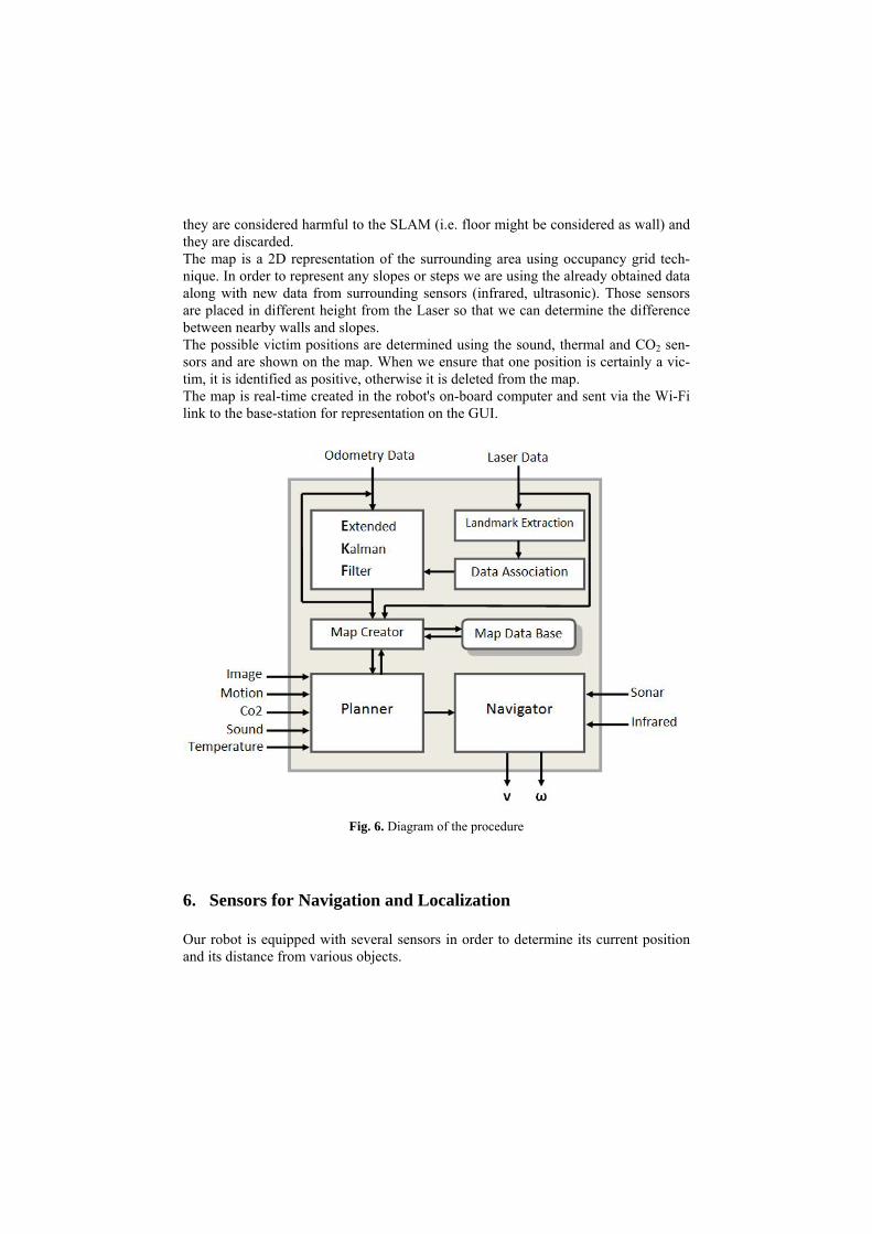
they are considered harmful to the SLAM (i.e. floor might be considered as wall) and they are discarded. The map is a 2D representation of the surrounding area using occupancy grid tech-nique. In order to represent any slopes or steps we are using the already obtained data along with new data from surrounding sensors (infrared, ultrasonic). Those sensors are placed in different height from the Laser so that we can determine the difference between nearby walls and slopes. The possible victim positions are determined using the sound, thermal and CO2 sen-sors and are shown on the map. When we ensure that one position is certainly a vic-tim, it is identified as positive, otherwise it is deleted from the map. The map is real-time created in the robot's on-board computer and sent via the Wi-Fi link to the base-station for representation on the GUI.
Fig. 6. Diagram of the procedure
6. Sensors for Navigation and Localization
Our robot is equipped with several sensors in order to determine its current position and its distance from various objects.
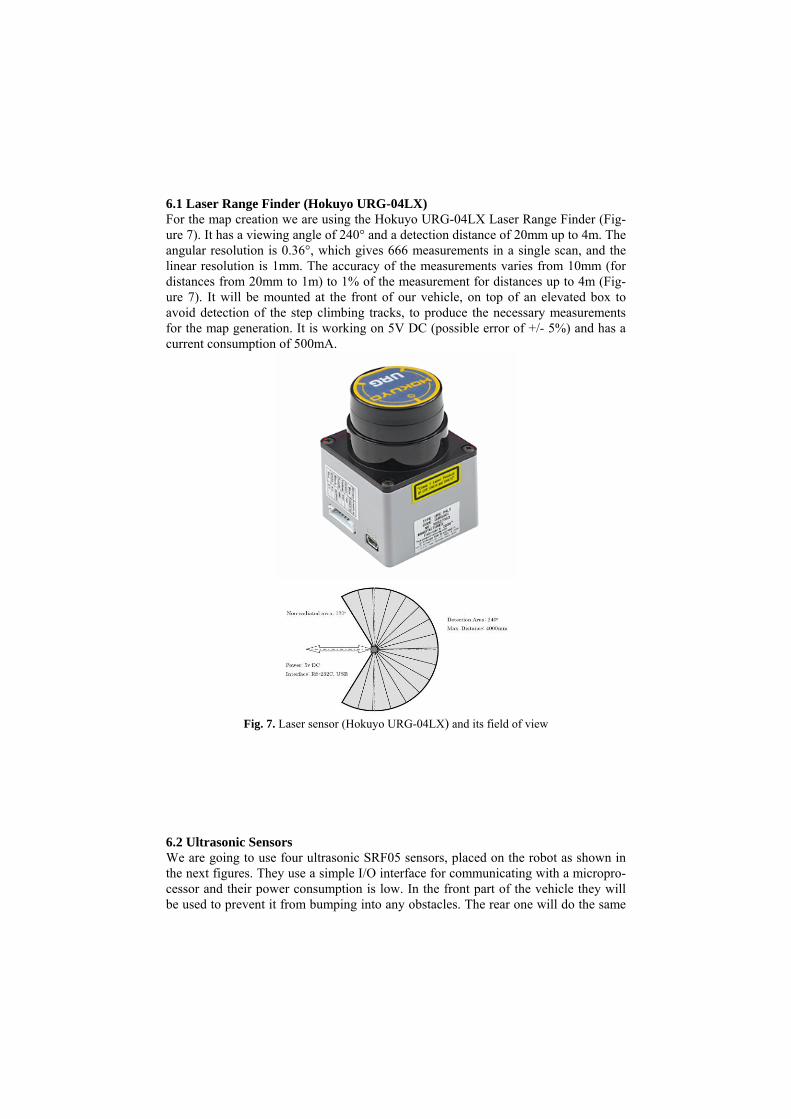
6.1 Laser Range Finder (Hokuyo URG-04LX) For the map creation we are using the Hokuyo URG-04LX Laser Range Finder (Fig-ure 7). It has a viewing angle of 240° and a detection distance of 20mm up to 4m. The angular resolution is 0.36°, which gives 666 measurements in a single scan, and the linear resolution is 1mm. The accuracy of the measurements varies from 10mm (for distances from 20mm to 1m) to 1% of the measurement for distances up to 4m (Fig-ure 7). It will be mounted at the front of our vehicle, on top of an elevated box to avoid detection of the step climbing tracks, to produce the necessary measurements for the map generation. It is working on 5V DC (possible error of +/- 5%) and has a current consumption of 500mA.
Fig. 7. Laser sensor (Hokuyo URG-04LX) and its field of view
6.2 Ultrasonic Sensors We are going to use four ultrasonic SRF05 sensors, placed on the robot as shown in the next figures. They use a simple I/O interface for communicating with a micropro-cessor and their power consumption is low. In the front part of the vehicle they will be used to prevent it from bumping into any obstacles. The rear one will do the same
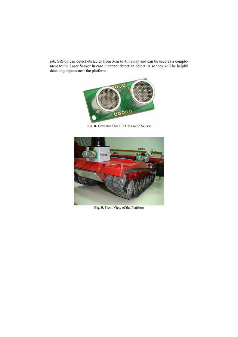
job. SRF05 can detect obstacles from 3cm to 4m away and can be used as a comple-ment to the Laser Sensor in case it cannot detect an object. Also they will be helpful detecting objects near the platform.
Fig. 8. Devantech SRF05 Ultrasonic Sensor
Fig. 9. Front View of the Platform

Fig. 10. Rear View of the Robot
6.3 Infrared Sensors Infrared sensors are placed both on the left and on the right side of the robot and they will cooperate with the sonars in order to give the distance of the robot from any obstacles with good accuracy. We will use GP2D120 infrared sensors. They have a short operating distance from 3cm to 30cm, so their main task will be to check the close surroundings of the robot. Two of them will be used to measure the distance between the bottom of the robot and the ground, so as to start an alarm in cases that the robot is in danger of falling. Also three of these sensors are going to be used on the camera head, one in order to show us the exact distance from a victim which might happen to be beside the camera and two others on the sides of the head, in order to prevent it from bumping, for example when entering into a hole. All of these sensors are connected to an Analog to Digital converter on the AVR microprocessor.

Fig. 11. Sharp GP2D120 IR Sensor
Fig. 12. Side View of the Robot
6.4 Accelerometer ADXL330 We decided to equip our robot with a triple axis accelerometer, which in co-operation with a compass will give us the position, speed and movement of the robot in the arena. As a result there will be no optical encoders to measure the distance travelled. The accelerometer will give us the acceleration of the robot in g (m/s2) and we will translate it using mathematical equations into x,y,z coordinates. ADXL330 can meas-ure acceleration up to 3g which is greater force than the one we will probably have. The accelerometer is mounted on a special board so as to have only three pins for output as acceleration in x,y,z axis and also a built-in voltage regulator. The accele-
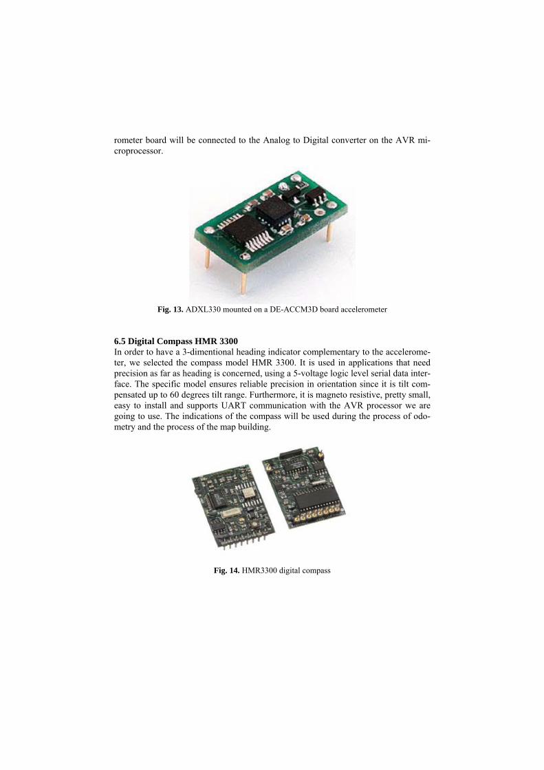
rometer board will be connected to the Analog to Digital converter on the AVR mi-croprocessor.
Fig. 13. ADXL330 mounted on a DE-ACCM3D board accelerometer
6.5 Digital Compass HMR 3300 In order to have a 3-dimentional heading indicator complementary to the accelerome-ter, we selected the compass model HMR 3300. It is used in applications that need precision as far as heading is concerned, using a 5-voltage logic level serial data inter-face. The specific model ensures reliable precision in orientation since it is tilt com-pensated up to 60 degrees tilt range. Furthermore, it is magneto resistive, pretty small, easy to install and supports UART communication with the AVR processor we are going to use. The indications of the compass will be used during the process of odo-metry and the process of the map building.
Fig. 14. HMR3300 digital compass
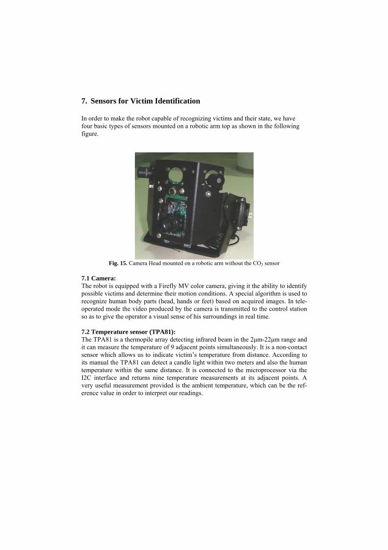
7. Sensors for Victim Identification In order to make the robot capable of recognizing victims and their state, we have four basic types of sensors mounted on a robotic arm top as shown in the following figure.
Fig. 15. Camera Head mounted on a robotic arm without the CO2 sensor
7.1 Camera: The robot is equipped with a Firefly MV color camera, giving it the ability to identify possible victims and determine their motion conditions. A special algorithm is used to recognize human body parts (head, hands or feet) based on acquired images. In tele-operated mode the video produced by the camera is transmitted to the control station so as to give the operator a visual sense of his surroundings in real time. 7.2 Temperature sensor (TPA81): The TPA81 is a thermopile array detecting infrared beam in the 2μm-22μm range and it can measure the temperature of 9 adjacent points simultaneously. It is a non-contact sensor which allows us to indicate victim’s temperature from distance. According to its manual the TPA81 can detect a candle light within two meters and also the human temperature within the same distance. It is connected to the microprocessor via the I2C interface and returns nine temperature measurements at its adjacent points. A very useful measurement provided is the ambient temperature, which can be the ref-erence value in order to interpret our readings.

Fig. 16. TPA81 Thermopile Array
7.3 CO2 sensor: The CO2 sensor installed on the robot has two modes of measuring the concentration of CO2 gas. The low range, from 0 to 10,000ppm and the high range from 0 to 100,000ppm. For the detection of the human respiration we will use the high range setting. The data will be collected and interpreted using the manufacturer’s software.
Fig. 17. Vernier CO2 Gas Sensor
7.4 Three Microphones: As far as the acoustic sensors are concerned, three electret condenser microphones are used for victim identification and navigation. They are mounted on the robotic arm’s top, so as to recognize the front left, front right and rear sounds. In order to identify the victim’s state by its sound.
Fig. 18. Microphone
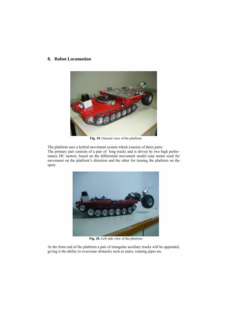
8. Robot Locomotion
Fig. 19. General view of the platform
The platform uses a hybrid movement system which consists of three parts: The primary part consists of a pair of long tracks and is driven by two high perfor-mance DC motors, based on the differential movement model (one motor used for movement on the platform’s direction and the other for turning the platform on the spot).
Fig. 20. Left side view of the platform
At the front end of the platform a pair of triangular auxiliary tracks will be appended, giving it the ability to overcome obstacles such as stairs, rotating pipes etc.
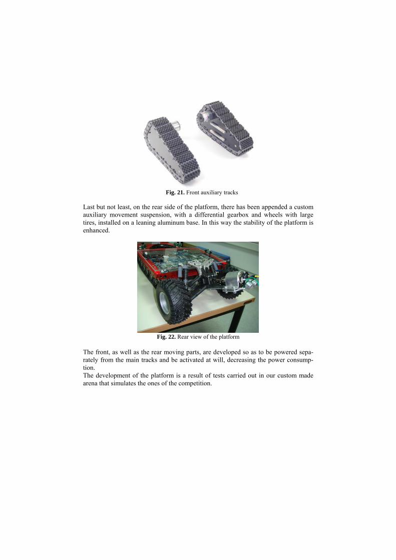
Fig. 21. Front auxiliary tracks
Last but not least, on the rear side of the platform, there has been appended a custom auxiliary movement suspension, with a differential gearbox and wheels with large tires, installed on a leaning aluminum base. In this way the stability of the platform is enhanced.
Fig. 22. Rear view of the platform
The front, as well as the rear moving parts, are developed so as to be powered sepa-rately from the main tracks and be activated at will, decreasing the power consump-tion. The development of the platform is a result of tests carried out in our custom made arena that simulates the ones of the competition.

Fig. 23. Going up the stairs (without the front tracks and the robotic arm)
The tests helped us towards take critical decisions concerning different parts of the platform. The final shape of the platform is a result of a profound analysis of those results.
Fig. 24. Overcoming two pipes
9. Other Mechanisms
The vehicle will carry a robotic arm with 5 degrees of freedom which will have a head on its top (Fig. 14). The robotic head supports 5 types of sensors. The robotic arm will be used in remote control and autonomous mode in order to reach a victim that is placed inside a box, higher than the vehicle. The height of the arm will make it
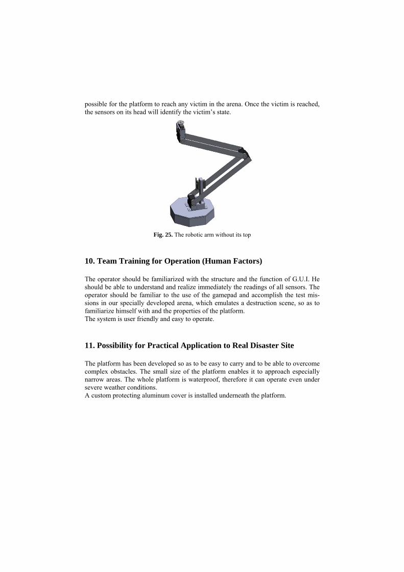
possible for the platform to reach any victim in the arena. Once the victim is reached, the sensors on its head will identify the victim’s state.
Fig. 25. The robotic arm without its top
10. Team Training for Operation (Human Factors)
The operator should be familiarized with the structure and the function of G.U.I. He should be able to understand and realize immediately the readings of all sensors. The operator should be familiar to the use of the gamepad and accomplish the test mis-sions in our specially developed arena, which emulates a destruction scene, so as to familiarize himself with and the properties of the platform. The system is user friendly and easy to operate.
11. Possibility for Practical Application to Real Disaster Site
The platform has been developed so as to be easy to carry and to be able to overcome complex obstacles. The small size of the platform enables it to approach especially narrow areas. The whole platform is waterproof, therefore it can operate even under severe weather conditions. A custom protecting aluminum cover is installed underneath the platform.
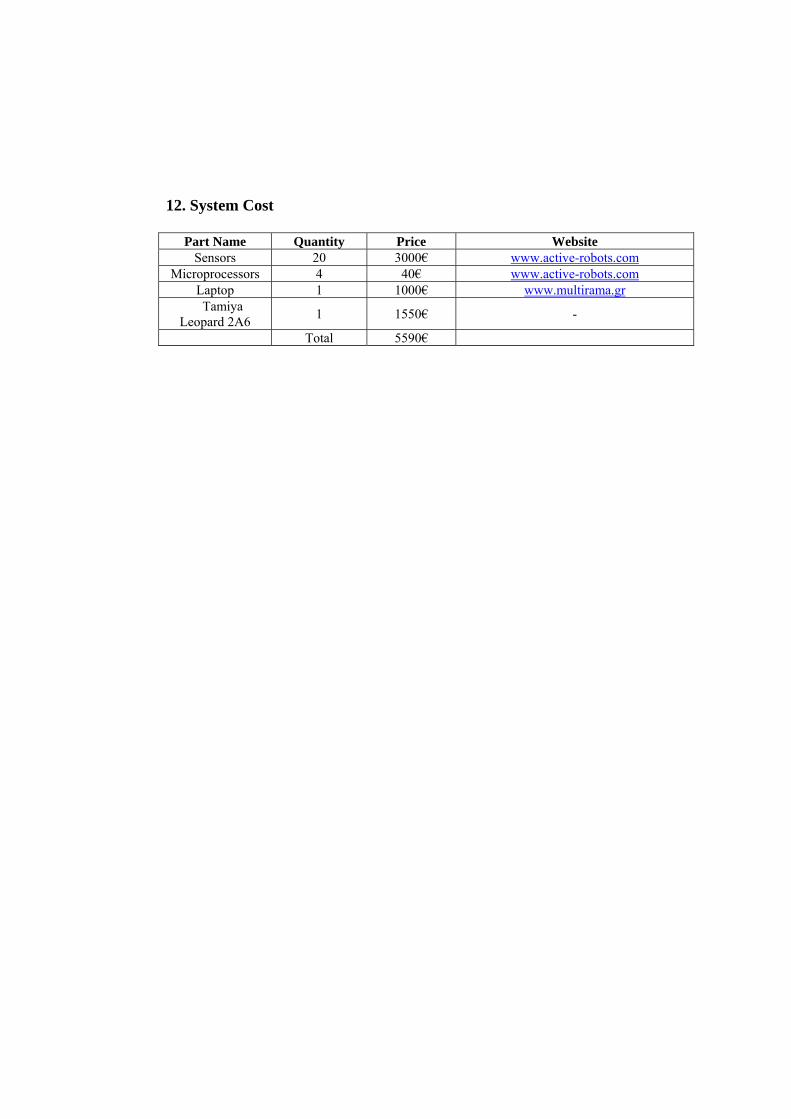
12. System Cost
Part Name Quantity Price Website Sensors 20 3000€ www.active-robots.com
Microprocessors 4 40€ www.active-robots.com Laptop 1 1000€ www.multirama.gr Tamiya
Leopard 2A6 1 1550€ -
Total 5590€