técnicas de posicionamiento y localización en sistemas de
TRANSCRIPT
Resumen — Con la implantación de las redes de comunicaciones móviles de Tercera Generación (UMTS), se
abre un nuevo abanico de posibilidades en cuanto al desarrollo de algoritmos para la gestión eficiente y
optimización de recursos radio. Con el fin de llevar a cabo dicha gestión se hace imprescindible disponer de
fuentes de información que permitan en cada momento distribuir y gestionar los recursos disponibles
maximizando la capacidad de la red.
El presente trabajo se centra en la localización de terminales móviles en base a parámetros de tiempo. La
técnica que hace uso del parámetro RACH Propagation Delay se emplea como un estimador de la distancia
entre la estación base y el terminal móvil, con un coste nulo en hardware. Adicionalmente, mediante la
información obtenida en el receptor RAKE integrado en el Nodo B, se presenta una técnica se seguimiento
de recursos radio, también con un coste cero de implementación hardware. Por último, se presenta una
técnica de localización personal mediante GPS asistido por la red.
Abstract — With the advent of the Third Generation in Mobile Communications (UMTS), a new range of
possibilities and resources become available for developing efficient network management and optimization
radio algorithms. In order to carry out this task it is necessary to have at one’s disposal the necessary sources
of information for distributing and managing in real time the available resources in the network maximizing
in this way the capacity.
The aim of this document is to present some novel mobile location techniques based in time parameters. The
technique based in a parameter known as RACH Propagation Delay is used as an estimator of the distance
between the base station and the mobile equipment, implying a zero cost hardware solution. By using the
information acquired from the RAKE receiver, which is integrated in the Node B, it is presented a technique
for tracking mobiles implying a zero cost hardware solution too. Finally, a technique for personal location
using the GPS network assistance is presented.
Autor: David Argilés Ortiz [email protected] Director: Narcís Cardona Marcet [email protected] Fecha de entrega: 03/12/2007
.
Técnicas de posicionamiento y localización en
sistemas de comunicaciones móviles UMTS Autor: David Argilés Ortiz
Director: Narcís Cardona Marcet
2 UMTS Location Techniques
INDEX
I. INTRODUCTION...................................................................................................4
II. LOCATION TECHNIQUES BASED ON TIME PARAMETERS ...................6
II.1. RACH PROPAGATION DELAY........................................................................ 6
II.1.1. RACH PROPAGATION DELAY DEFINITION ............................................ 6
II.1.2. TOOLS AND EVALUATION PROCEDURE ................................................ 6
II.1.3. RESULTS..................................................................................................... 10
II.1.3.1. CHIP ERROR VS DISTANCE TO BS ................................................. 10
II.1.3.2. CHIP ERROR VS EC/NO.................................................................... 13
II.1.3.3. CHIP ERROR VS RSSI........................................................................ 14
II.1.3.4. CHIP ERROR VS RSCP ...................................................................... 15
II.1.3.5. CHIP ERROR VS SPEED ................................................................... 16
II.1.4. CONCLUSIONS .......................................................................................... 17
II.2. FINGER TRACKING .......................................................................................... 18
II.2.1. THE RAKE RECEIVER TIMING DATA PROVIDED BY SLT ................... 18
II.2.2. TRIALS ........................................................................................................ 19
II.2.2.1. FIRST TRIAL....................................................................................... 20
II.2.2.2. SECOND TRIAL.................................................................................. 20
II.2.2.3. THIRD TRIAL ..................................................................................... 21
II.2.2.4. FOURTH TRIAL ................................................................................. 22
II.2.3. CONCLUSIONS .......................................................................................... 22
UMTS Location Techniques
3
II.3. ASSISTED-GPS ................................................................................................... 23
II.3.1. GPS BASIS................................................................................................... 23
II.3.2. WHY A-GPS?............................................................................................... 24
II.3.3. REAL MEASUREMENT REPORT .............................................................. 25
II.3.4. WHEN WILL A-GPS BE READY FOR COMMERCIAL USE? .................. 29
III. CONCLUSIONS................................................................................................... 30
ABBREVIATIONS....................................................................................................... 31
ACKNOWLEDGEMENTS......................................................................................... 32
REFERENCES ............................................................................................................. 33
ANNEXE ....................................................................................................................... 34
4 UMTS Location Techniques
I. INTRODUCTION
With the advent of the Universal Mobile Telecommunications System (UMTS), 3rd generation in
mobile communications, a new range of possibilities and resources are available for developing
mobile location techniques. UMTS networks and user equipments (UE) offer a favorable technical
basis for location-based services.
The initial UMTS deployment was carried out for covering the densely built urban areas, where
the user densities are high. These microcellular environments are in favour of commercial service
providers and the possibilities to use location information are wide. In these areas high location
accuracy is more valuable but as a drawback the effects of multipath propagation and non-line-of-
sight (NLOS) situations are more significant. Conventional location techniques based on power
trilateration rely on line-of-sight (LOS) path between the base station (BS) antenna and the mobile
terminal (MT). In urban environment the LOS assumption is rarely valid for three BS at the same
time, which degrades the location performance (availability and accuracy).
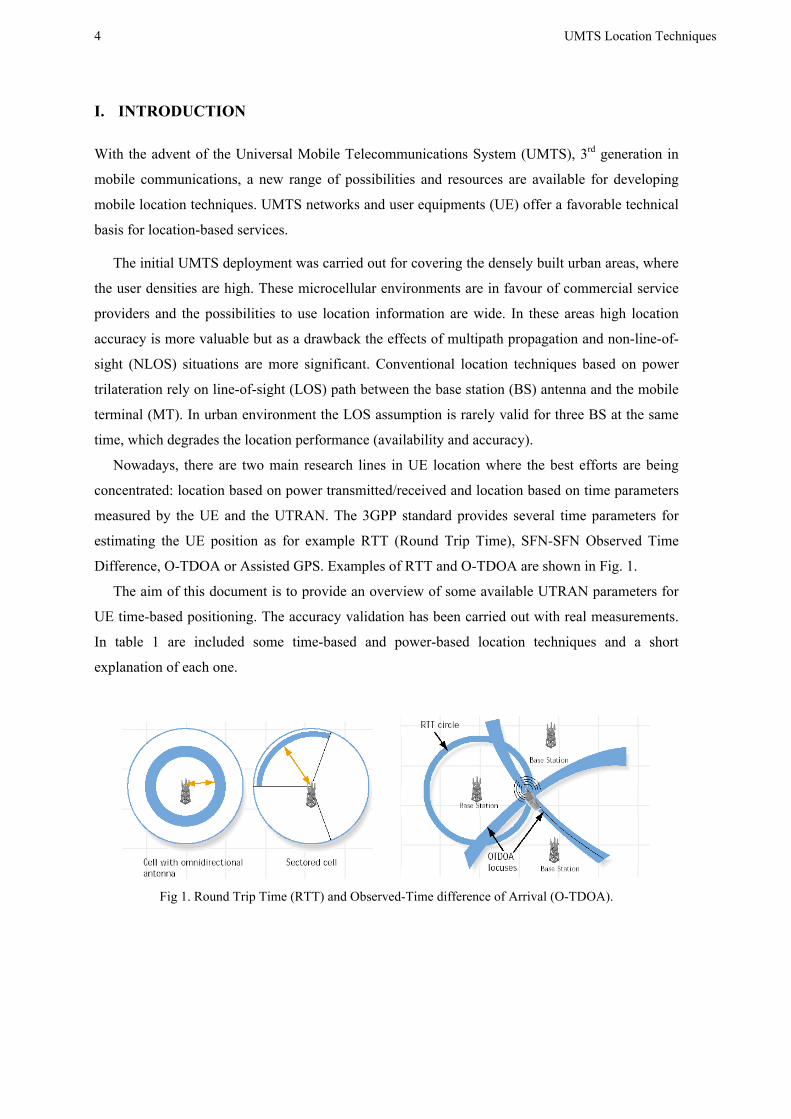
Nowadays, there are two main research lines in UE location where the best efforts are being
concentrated: location based on power transmitted/received and location based on time parameters
measured by the UE and the UTRAN. The 3GPP standard provides several time parameters for
estimating the UE position as for example RTT (Round Trip Time), SFN-SFN Observed Time
Difference, O-TDOA or Assisted GPS. Examples of RTT and O-TDOA are shown in Fig. 1.
The aim of this document is to provide an overview of some available UTRAN parameters for
UE time-based positioning. The accuracy validation has been carried out with real measurements.
In table 1 are included some time-based and power-based location techniques and a short
explanation of each one.
Fig 1. Round Trip Time (RTT) and Observed-Time difference of Arrival (O-TDOA).

UMTS Location Techniques
5
LOCATION TECHNIQUE DESCRIPTION
Cell ID The SRNC determines the identification of the cell providing coverage for the target UE
TIME BASED TECHNIQUES
RACH Propagation Delay RACH Propagation Delay parameter measured at the RRC Connection Setup message provides an inicial distance estimation to BS
SFN-SFN and UE_RxTx Location technique based on the SFN-SFN observed time difference and UE_RxTx measured at the UE.
Rake Receiver Multipath components (fingers) received at the Node B can be used to estimate movement variations from an initial fixed referente position.
Assisted – GPS The UE integrates a simplified GPS receiver which is assisted by the UTRAN by means of sending useful GPS parameters to the UE
Round Trip Time Estimated delay between the Node-B and the target UE. SRNC sends to the desired NodeB a RTT Request. The Node B meassures the RTT
and responses with a RTT Measurement to the SRNC
POWER BASED TECHNIQUES
Eb/No Consists on calculating the pseudo-pathloss and distance. It depends on the network load and requires calibration.
Hot Spot Update to UMTS UMTS HotSpot locator based on NetPlan predictions. Consists on minimizing a cost function.
Table 1. Time-based and power-based location techniques
6 UMTS Location Techniques
II. LOCATION TECHNIQUES BASED ON TIME PARAMETERS
II.1. RACH PROPAGATION DELAY
II.1.1. RACH PROPAGATION DELAY DEFINITION
The RACH Propagation Delay parameter is defined by 3GPP in [1] [2] as:
Propagation delay = (TRX – TTX – 2560)/2
where:
• TTX is the transmission time of AICH access slot (n-2-AICH transmission timing),
where 0 ≤ (n-2-AICH Transmission Timing) ≤ 14 and AICH_Transmission_Timing is
valued 0 or 1.
• TRX is the time of reception of the beginning (the first detected path, in time) of the
PRACH message from the UE at PRACH access slot n.
The 3GPP accuracy provided by the RACH Propagation Delay is ± 2 chip and the Propagation
delay reporting range is from 0 ... 765 chip.
II.1.2. TOOLS AND EVALUATION PROCEDURE
In order to evaluate the accuracy provided by the RACH Propagation Delay, real data obtained
from trial networks have been used. On the other hand, the GPS position of UE and Base Stations
(BS) are available for computing the associated error with the RACH Propagation Delay
estimation.
SLT (SMAP Local Terminal) and TEMS W-CDMA are both tools used in the process of
evaluating the method and determining the error of the reported RACH Propagation Delay value.
EVALUATION PROCEDURE
TEMS W-CDMA
In TEMS-WCDMA, the GPS position of UE and BS and the associated call Layer 3 RRC
messages are available. Next, the steps followed in TEMS are described:
1- Open the log and play it.
2- Extract the U-RNTI from the RRC Connection Setup message. The U-RNTI identifies a
call and allows linking this U-RNTI in TEMS with the corresponding call in SLT. The U-
RNTI is provided in binary format so it must be translated into decimal format in order to
link it with the provided by SLT.
Example : U-RNTIbin = 110000001000011000001101
U-RNTIdec = 12617229
UMTS Location Techniques
7
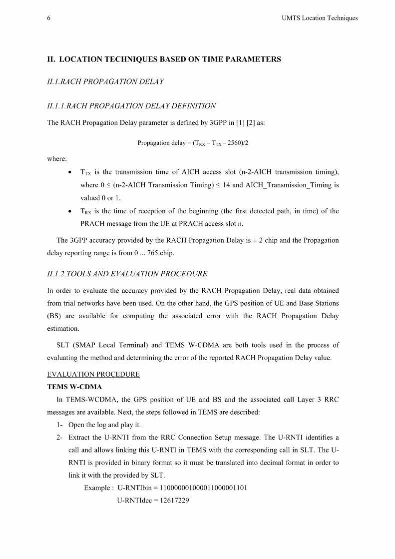
Fig. 2 shows a screen shot of the RRC Connection Setup message and offers the fields where
the U-RNTI must be extracted from. It is important to note that the U-RNTI is a concatenation of
the S-RNC identity and the S-RNTI.
Fig 2. U-RNTI extraction from TEMS W-CDMA
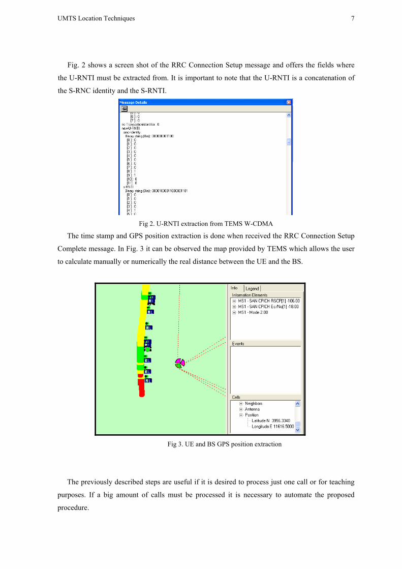
The time stamp and GPS position extraction is done when received the RRC Connection Setup
Complete message. In Fig. 3 it can be observed the map provided by TEMS which allows the user
to calculate manually or numerically the real distance between the UE and the BS.
Fig 3. UE and BS GPS position extraction
The previously described steps are useful if it is desired to process just one call or for teaching
purposes. If a big amount of calls must be processed it is necessary to automate the proposed
procedure.

8 UMTS Location Techniques
In order to automate the procedure, a TEMS report must be generated from Logfile + Export
Logfile + Add Export Order + Options selected in Fig. 4. The selected options have been
configured for making easier the post processing task.
The created report will be post processed by a PERL script which will extract the U-RNTI from
the RRC Connection Setup message and the UE GPS position when it is received the RRC
Connection Setup Complete. TEMS doesn’t provide the decoded U-RNTI so it is necessary to
decode the hexadecimal string using an external application called ASNParser. The PERL script
runs the ASNParser application and decodes the hexadecimal string corresponding to the RRC
Connection Setup message. Finally it is extracted the U-RNTI from both fields, the S-RNC identity
and the S-RNTI.
The DOS command line for running the ASNParser application must accomplish the following
format in order to process the hexadecimal string in the right way.
>> ASNParser <Protocol> <RRC Message type> <Message>
The RRC Connection Setup message belongs to the RRC protocol (value 1) and it is into the
DL-Common Control Channel (DL-CCCH, value 3), so the final command line is:
>> ASNParser 1 3 hexadecimal_string
Fig 4. Selected TEMS IEs
SLT (SMAP Local Terminal)
The RACH Propagation Delay value is reported into the Radio Link Setup Request message
which is captured by SLT. If it is desired to carry out the procedure manually, the steps to be
followed in SLT are the following:
1- Open the SLT log.
2- Open the call list and select the desired U-RNTI (12617229)
3- Open the RNC message flow and play the log. The call trace messages will appear in the
message flow window.
UMTS Location Techniques
9
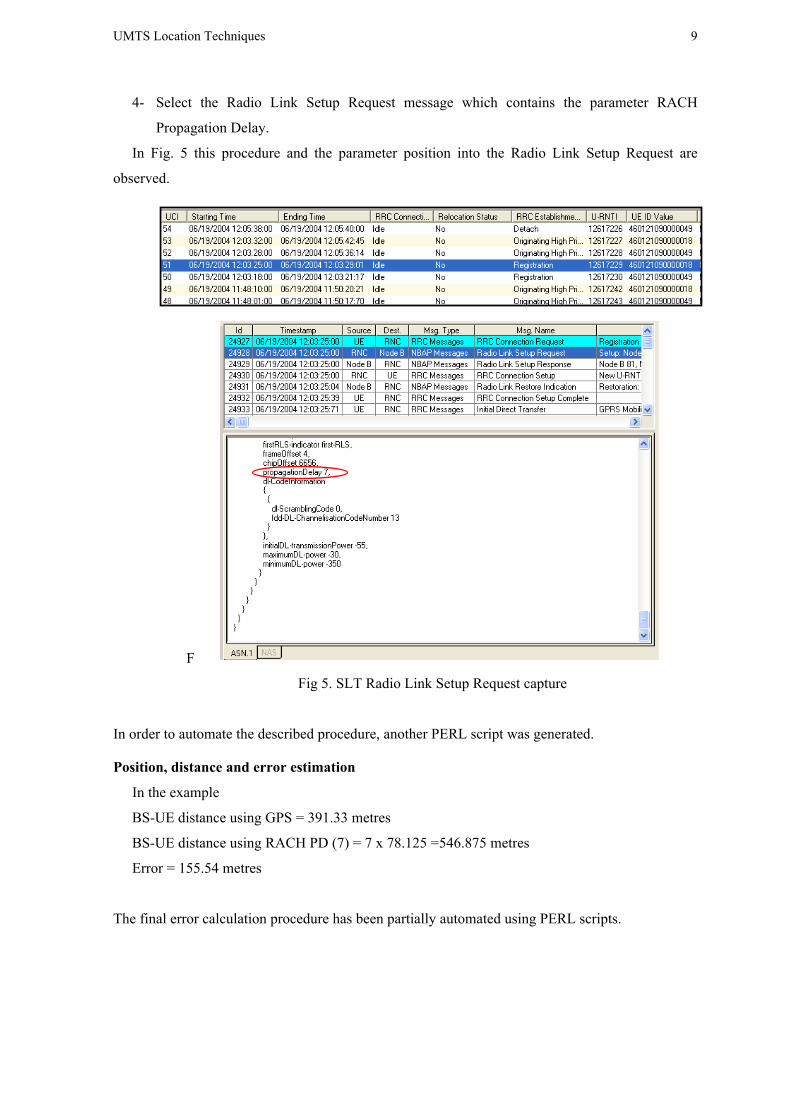
4- Select the Radio Link Setup Request message which contains the parameter RACH
Propagation Delay.
In Fig. 5 this procedure and the parameter position into the Radio Link Setup Request are
observed.
F
Fig 5. SLT Radio Link Setup Request capture
In order to automate the described procedure, another PERL script was generated.
Position, distance and error estimation
In the example
BS-UE distance using GPS = 391.33 metres
BS-UE distance using RACH PD (7) = 7 x 78.125 =546.875 metres
Error = 155.54 metres
The final error calculation procedure has been partially automated using PERL scripts.

10 UMTS Location Techniques
II.1.3. RESULTS
In order to check the accuracy of the 3GPP RACH Propagation Delay, up to 1.258 calls have been
analysed using the described process in section 2 (calls extracted from trial logs). The process has
been partially automated applying PERL scripts to TEMS and SLT logs.
The aim of this section is to evaluate how the error of the reported distance by the RACH
Propagation Delay message varies with the real distance to the BS, Received Signal Code Power
(RSCP), Ec/No, Received Strength Signal Indicator (RSSI) and speed.
II.1.3.1. CHIP ERROR VS DISTANCE TO BS
Fig. 6 shows the histogram of the real measured GPS distances from UE to BS for 1.258 analysed
calls. It can be observed that the analysis have been focused between 0 to 800 metres of distance to
the BS because of the samples availability.
0 200 400 600 800 1000 1200 1400 16000
20
40
60
80
100
120
140
160
Distance (m)
Sam
ples
Distance histogram
Fig 6. Real BS histogram
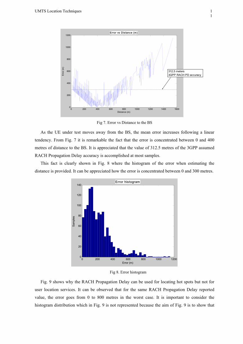
In Fig. 7, it is represented the “Error vs Distance to BS”. It is important to note that it has been
plotted the absolute error value. When the UE is close to the BS, the error is high because the
reported RACH Propagation Delay is not correct maybe due to the hearability problem or
multipath effects in the channel.
UMTS Location Techniques
11
0 200 400 600 800 1000 1200 1400 16000
200
400
600
800
1000
1200
Distance (m)
Erro
r (m
)
Error vs Distance (m)
312,5 meters3GPP RACH PD accuracy
Fig 7. Error vs Distance to the BS
As the UE under test moves away from the BS, the mean error increases following a linear
tendency. From Fig. 7 it is remarkable the fact that the error is concentrated between 0 and 400
metres of distance to the BS. It is appreciated that the value of 312.5 metres of the 3GPP assumed
RACH Propagation Delay accuracy is accomplished at most samples.
This fact is clearly shown in Fig. 8 where the histogram of the error when estimating the
distance is provided. It can be appreciated how the error is concentrated between 0 and 300 metres.
0 200 400 600 800 1000 12000
20
40
60
80
100
120
140
Error (m)
Sam
ples
Error histogram
Fig 8. Error histogram
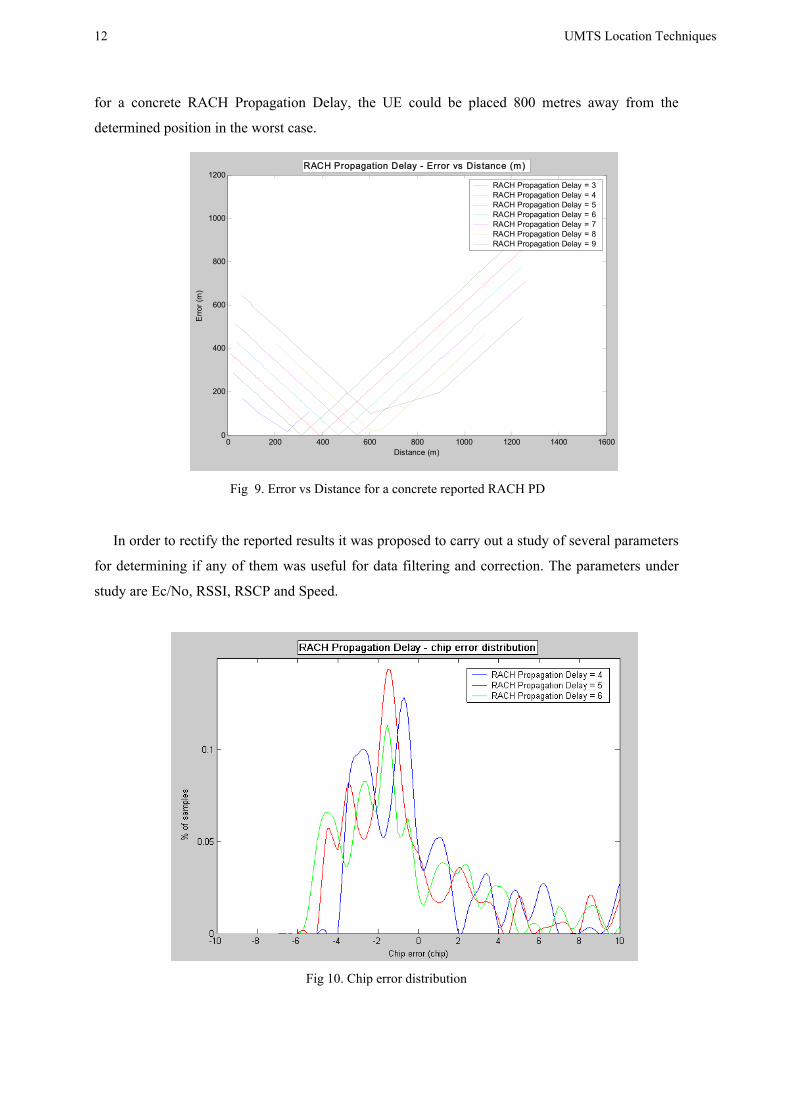
Fig. 9 shows why the RACH Propagation Delay can be used for locating hot spots but not for
user location services. It can be observed that for the same RACH Propagation Delay reported
value, the error goes from 0 to 800 metres in the worst case. It is important to consider the
histogram distribution which in Fig. 9 is not represented because the aim of Fig. 9 is to show that
12 UMTS Location Techniques
for a concrete RACH Propagation Delay, the UE could be placed 800 metres away from the
determined position in the worst case.
0 200 400 600 800 1000 1200 1400 16000
200
400
600
800
1000
1200
Distance (m)
Erro
r (m
)
RACH Propagation Delay - Error vs Distance (m)
RACH Propagation Delay = 3RACH Propagation Delay = 4RACH Propagation Delay = 5RACH Propagation Delay = 6RACH Propagation Delay = 7RACH Propagation Delay = 8RACH Propagation Delay = 9
Fig 9. Error vs Distance for a concrete reported RACH PD
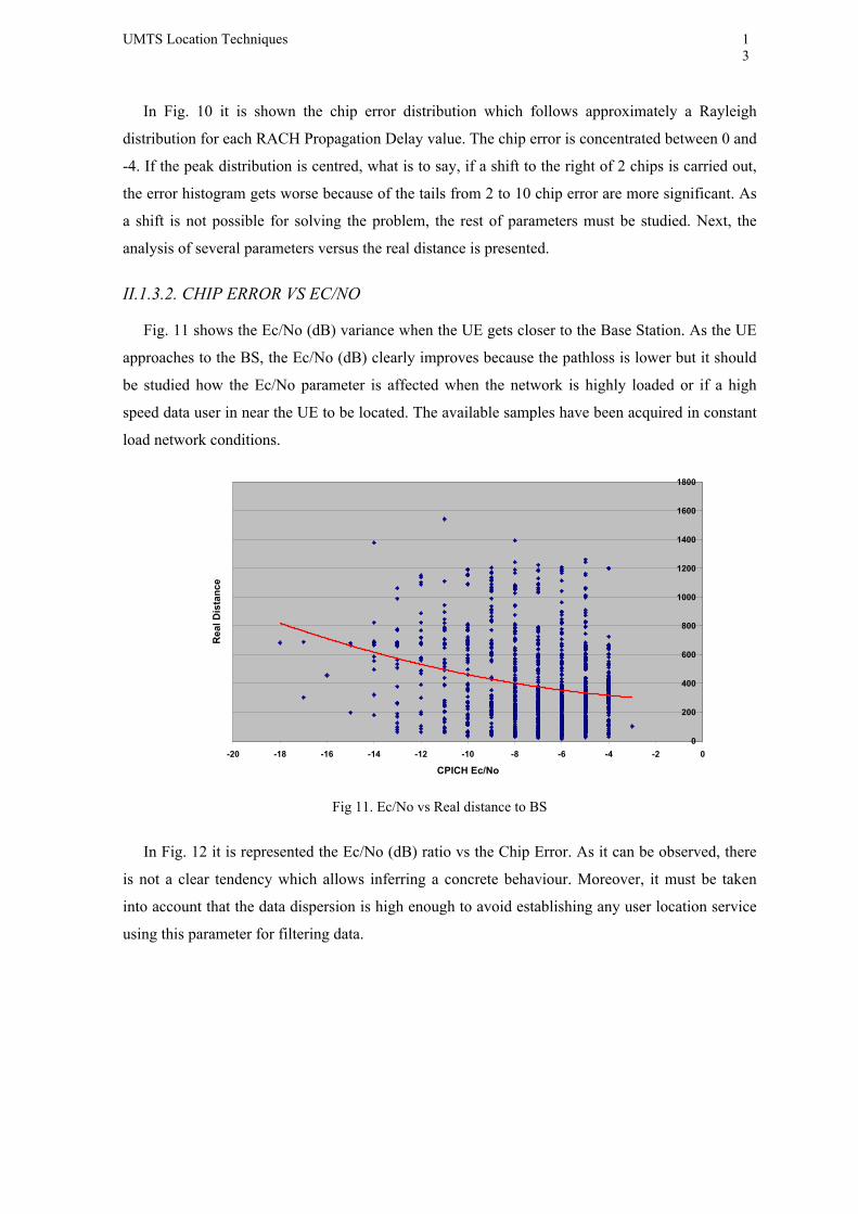
In order to rectify the reported results it was proposed to carry out a study of several parameters
for determining if any of them was useful for data filtering and correction. The parameters under
study are Ec/No, RSSI, RSCP and Speed.
Fig 10. Chip error distribution
UMTS Location Techniques
13
In Fig. 10 it is shown the chip error distribution which follows approximately a Rayleigh
distribution for each RACH Propagation Delay value. The chip error is concentrated between 0 and
-4. If the peak distribution is centred, what is to say, if a shift to the right of 2 chips is carried out,
the error histogram gets worse because of the tails from 2 to 10 chip error are more significant. As
a shift is not possible for solving the problem, the rest of parameters must be studied. Next, the
analysis of several parameters versus the real distance is presented.
II.1.3.2. CHIP ERROR VS EC/NO
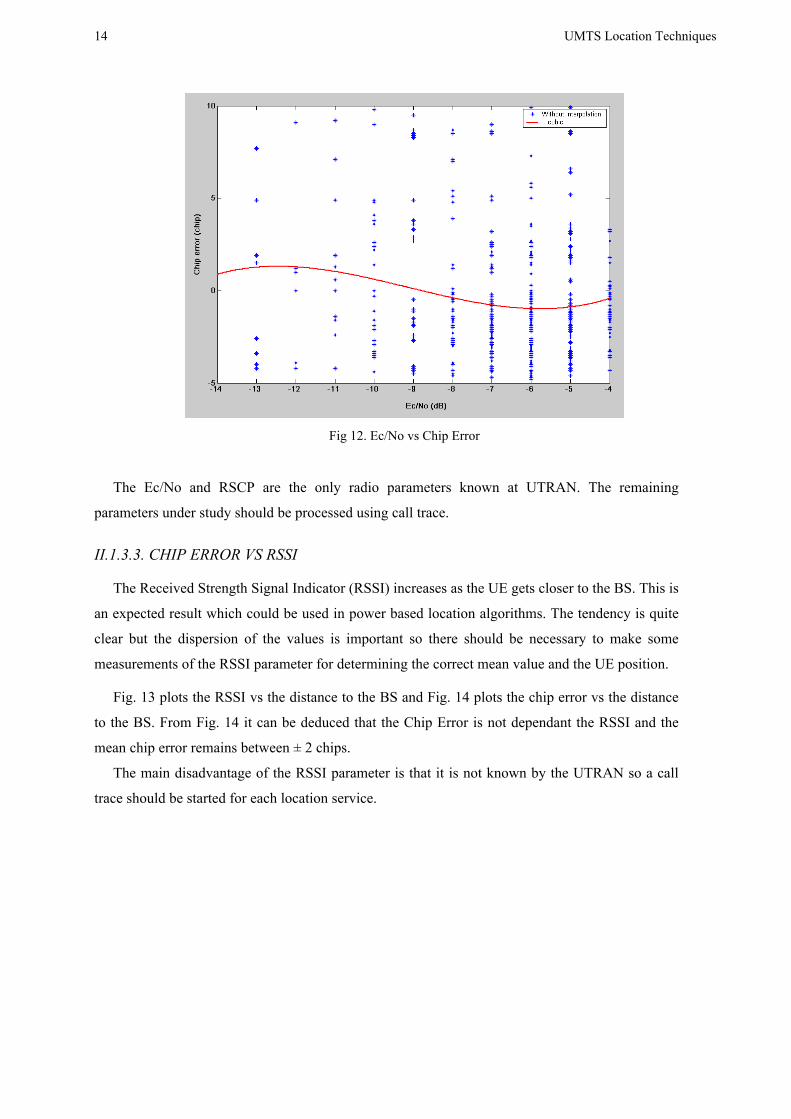
Fig. 11 shows the Ec/No (dB) variance when the UE gets closer to the Base Station. As the UE
approaches to the BS, the Ec/No (dB) clearly improves because the pathloss is lower but it should
be studied how the Ec/No parameter is affected when the network is highly loaded or if a high
speed data user in near the UE to be located. The available samples have been acquired in constant
load network conditions.
0
200
400
600
800
1000
1200
1400
1600
1800
-20 -18 -16 -14 -12 -10 -8 -6 -4 -2 0
CPICH Ec/No
Rea
l Dis
tanc
e
Fig 11. Ec/No vs Real distance to BS
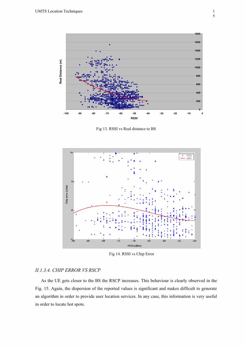
In Fig. 12 it is represented the Ec/No (dB) ratio vs the Chip Error. As it can be observed, there
is not a clear tendency which allows inferring a concrete behaviour. Moreover, it must be taken
into account that the data dispersion is high enough to avoid establishing any user location service
using this parameter for filtering data.
14 UMTS Location Techniques
Fig 12. Ec/No vs Chip Error
The Ec/No and RSCP are the only radio parameters known at UTRAN. The remaining
parameters under study should be processed using call trace.
II.1.3.3. CHIP ERROR VS RSSI
The Received Strength Signal Indicator (RSSI) increases as the UE gets closer to the BS. This is
an expected result which could be used in power based location algorithms. The tendency is quite
clear but the dispersion of the values is important so there should be necessary to make some
measurements of the RSSI parameter for determining the correct mean value and the UE position.
Fig. 13 plots the RSSI vs the distance to the BS and Fig. 14 plots the chip error vs the distance
to the BS. From Fig. 14 it can be deduced that the Chip Error is not dependant the RSSI and the
mean chip error remains between ± 2 chips.
The main disadvantage of the RSSI parameter is that it is not known by the UTRAN so a call
trace should be started for each location service.
UMTS Location Techniques
15
0
200
400
600
800
1000
1200
1400
1600
1800
-100 -90 -80 -70 -60 -50 -40 -30 -20 -10 0
RSSI
Rea
l Dis
tanc
e (m
)
Fig 13. RSSI vs Real distance to BS
Fig 14. RSSI vs Chip Error
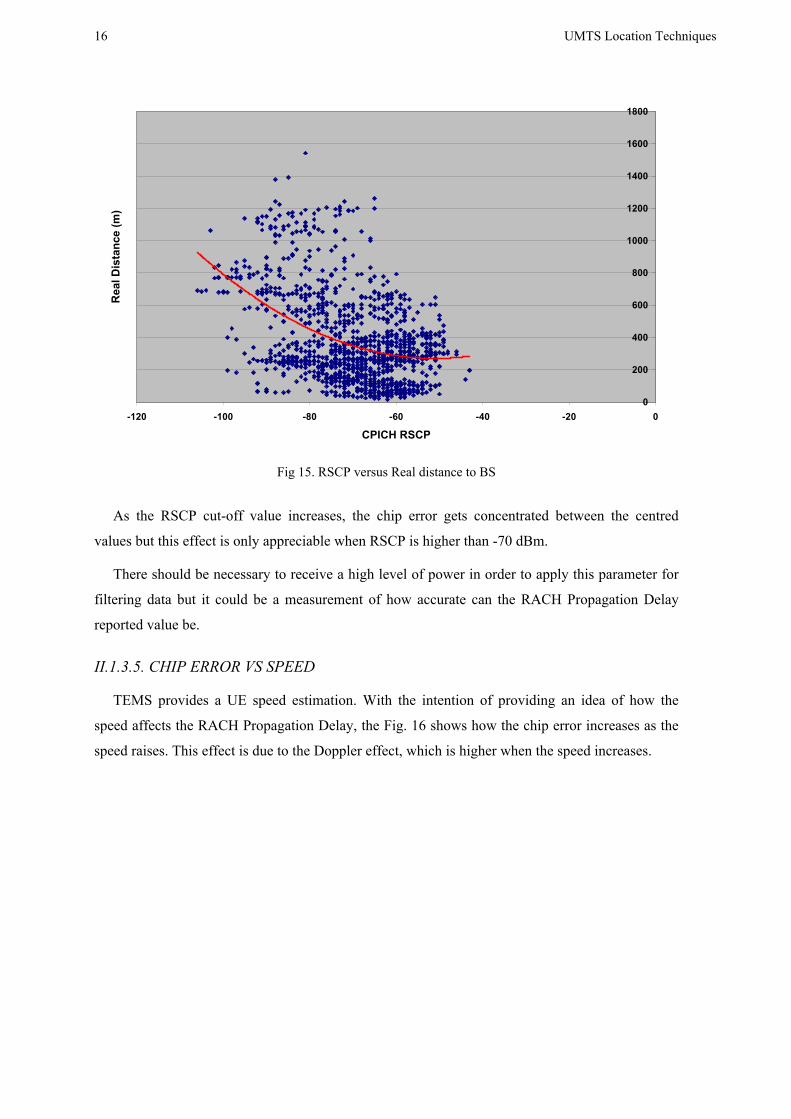
II.1.3.4. CHIP ERROR VS RSCP
As the UE gets closer to the BS the RSCP increases. This behaviour is clearly observed in the
Fig. 15. Again, the dispersion of the reported values is significant and makes difficult to generate
an algorithm in order to provide user location services. In any case, this information is very useful
in order to locate hot spots.
16 UMTS Location Techniques
0
200
400
600
800
1000
1200
1400
1600
1800
-120 -100 -80 -60 -40 -20 0
CPICH RSCP
Rea
l Dis
tanc
e (m
)
Fig 15. RSCP versus Real distance to BS
As the RSCP cut-off value increases, the chip error gets concentrated between the centred
values but this effect is only appreciable when RSCP is higher than -70 dBm.
There should be necessary to receive a high level of power in order to apply this parameter for
filtering data but it could be a measurement of how accurate can the RACH Propagation Delay
reported value be.
II.1.3.5. CHIP ERROR VS SPEED
TEMS provides a UE speed estimation. With the intention of providing an idea of how the
speed affects the RACH Propagation Delay, the Fig. 16 shows how the chip error increases as the
speed raises. This effect is due to the Doppler effect, which is higher when the speed increases.

UMTS Location Techniques
17
Fig 16. Speed vs Chip Error
II.1.4. CONCLUSIONS
The RACH Propagation Delay provides a ± 2 chips accuracy which is directly translated into
312.5 metres of uncertainty. This accuracy is accomplished at most cases but the dispersion of
values is not good enough for enabling user location services. Anyway, hot spot location systems
could be feed with that kind of data.
In order to improve the RACH Propagation Delay reported value, some radio parameters have
been studied but none of them have been good enough for solving the chip error obtained values.
Moreover, some of them are not available at UTRAN what would force to start a call trace session
when a location service is requested.
The RSSI an RSCP parameters could be useful when locating UEs using power based
algorithms. The RSCP is not available at UTRAN yet but in future its information could be
available for being post-processed at a software application. The accuracy provided by RSCP is
good enough for hot spot location.
The Ec/No parameter is available at UTRAN but it is not recommended to be used for power
based location because it is dependant of the cell load. Anyway, it is not able to correct chip error
deviations.
Finally, it is remarkable the fact that the RACH Propagation Delay is a parameter that is only
available when the call sets up and not during the call. This parameters provides an initial
circumference over the cell, a distance to the base station, but complementary location techniques
as power based triangulation, finger tracking, SFN-SFN observed time difference or Round Trip
Time (RTT) should be applied in order to determine a concrete UE position.

18 UMTS Location Techniques
II.2. FINGER TRACKING
The Node B implements a RAKE receiver which takes advantage of the multipath radio
environment selecting several multipath contributions and adding them in phase. With this
procedure it is recovered disperse energy in the multipath environment and a diversity mechanism
is provided. This procedure implies high timing requirements for each finger. This timing
information is the data source for the proposed technique.
The aim of the finger tracker is to determine the distance from the UE to an initial position
which can be fixed at any moment of the call. Since the initial position is fixed, relative delays of
fingers are computed in order to find out if the UE is getting closer or moving away.
Motorola SLT and TEMS Investigation WCDMA are both tools used for determining the
validity of the proposed method. Motorola SLT provides information about the timing status of
each finger of the RAKE receiver and TEMS Investigation WCDMA is linked to a GPS receiver
which informs about the exact GPS position. Applying this scheme, with both tools synchronized,
it is possible to validate the accuracy of the proposed distance and movement estimation.
II.2.1. THE RAKE RECEIVER TIMING DATA PROVIDED BY SLT
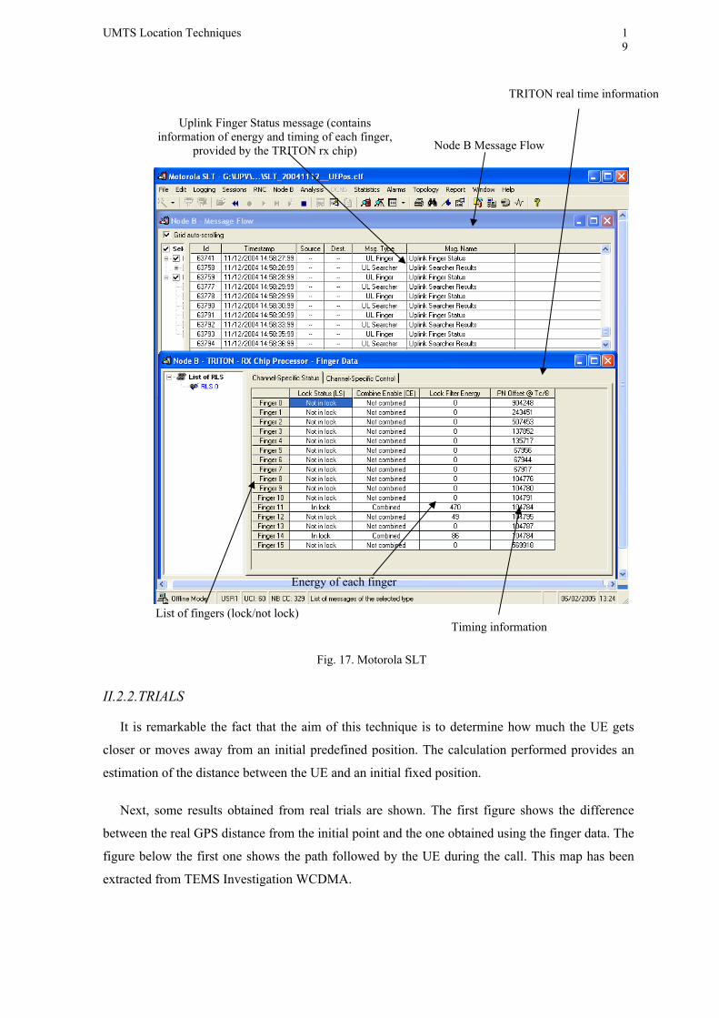
Fig. 17 shows a Motorola SLT screen shot with the information corresponding to the data that
comes from the TRITON chip integrated in the Node B. This chip implements the RAKE receiver.
On the other hand, the message flow at Node B is offered. It is possible to open a message and get
the information that is graphically displayed in the lower window. It is reported information from
the searcher and the finger status. The searcher component looks for new contributions with energy
enough to be tracked by a finger. The “Uplink Finger Status” message provides accurate
information about the energy and timing of each finger. This information is used for establishing
an initial time reference and the later calculation of time differences from that initial fixed
reference which corresponds to a physical position in the map.
Taking as a fixed reference a PN Offset value, which has an accuracy of Tc/8, differences from
that fixed value are calculated in order to estimate the position variation.
UMTS Location Techniques
19
Fig. 17. Motorola SLT
II.2.2. TRIALS
It is remarkable the fact that the aim of this technique is to determine how much the UE gets
closer or moves away from an initial predefined position. The calculation performed provides an
estimation of the distance between the UE and an initial fixed position.
Next, some results obtained from real trials are shown. The first figure shows the difference
between the real GPS distance from the initial point and the one obtained using the finger data. The
figure below the first one shows the path followed by the UE during the call. This map has been
extracted from TEMS Investigation WCDMA.
Node B Message Flow
Uplink Finger Status message (contains information of energy and timing of each finger,
provided by the TRITON rx chip)
List of fingers (lock/not lock)
Energy of each finger
Timing information
TRITON real time information
20 UMTS Location Techniques
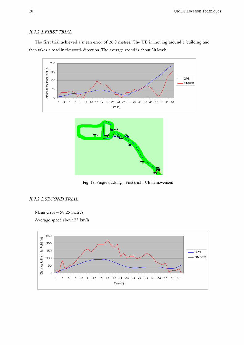
II.2.2.1. FIRST TRIAL
The first trial achieved a mean error of 26.8 metres. The UE is moving around a building and
then takes a road in the south direction. The average speed is about 30 km/h.
0
50
100
150
200
1 3 5 7 9 11 13 15 17 19 21 23 25 27 29 31 33 35 37 39 41 43
Time (s)
Dis
tanc
e to
the
Initia
l Poi
nt (m
)
GPS
FINGER
Fig. 18. Finger tracking – First trial – UE in movement II.2.2.2. SECOND TRIAL
Mean error = 58.25 metres
Average speed about 25 km/h
0
50
100
150
200
250
1 3 5 7 9 11 13 15 17 19 21 23 25 27 29 31 33 35 37 39
Time (s)
Dis
tanc
e to
the
Initia
l Poi
nt (m
)
GPS
FINGER
UMTS Location Techniques
21
Fig. 19. Finger tracking – Second trial – UE in movement
It would be interesting to complete the study with several speeds in order to estimate how much
the Doppler effect implies more o less accuracy. At the moment, no more data is available.
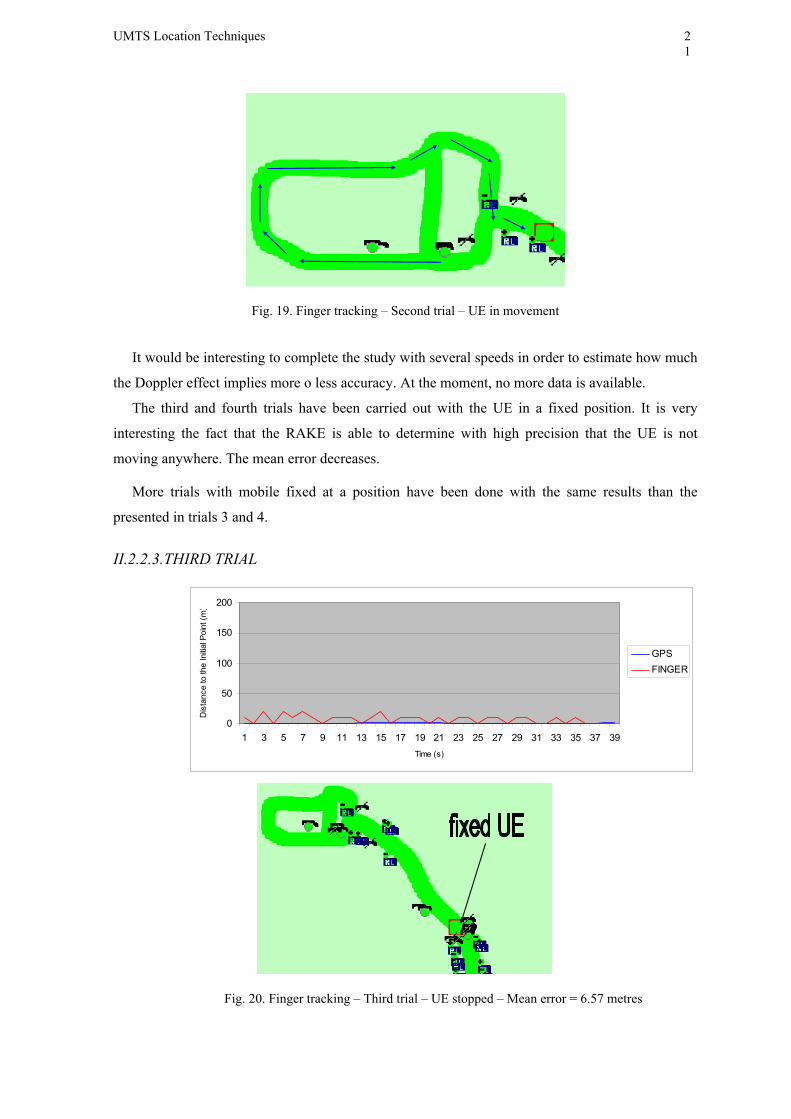
The third and fourth trials have been carried out with the UE in a fixed position. It is very
interesting the fact that the RAKE is able to determine with high precision that the UE is not
moving anywhere. The mean error decreases.
More trials with mobile fixed at a position have been done with the same results than the
presented in trials 3 and 4.
II.2.2.3. THIRD TRIAL
0
50
100
150
200
1 3 5 7 9 11 13 15 17 19 21 23 25 27 29 31 33 35 37 39Time (s)
Dis
tanc
e to
the
Initia
l Poi
nt (m
)
GPSFINGER
Fig. 20. Finger tracking – Third trial – UE stopped – Mean error = 6.57 metres
22 UMTS Location Techniques
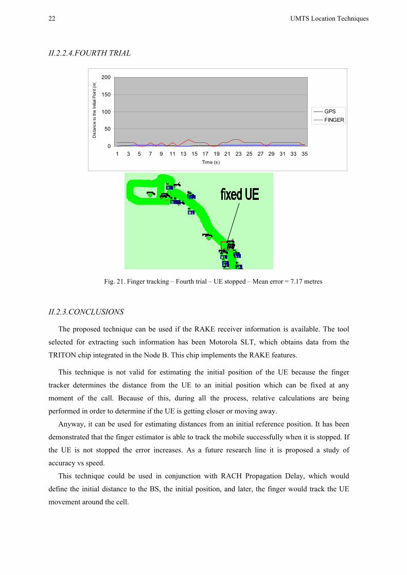
II.2.2.4. FOURTH TRIAL
0
50
100
150
200
1 3 5 7 9 11 13 15 17 19 21 23 25 27 29 31 33 35Time (s)
Dis
tanc
e to
the
Initia
l Poi
nt (m
)
GPSFINGER
Fig. 21. Finger tracking – Fourth trial – UE stopped – Mean error = 7.17 metres
II.2.3. CONCLUSIONS
The proposed technique can be used if the RAKE receiver information is available. The tool
selected for extracting such information has been Motorola SLT, which obtains data from the
TRITON chip integrated in the Node B. This chip implements the RAKE features.
This technique is not valid for estimating the initial position of the UE because the finger
tracker determines the distance from the UE to an initial position which can be fixed at any
moment of the call. Because of this, during all the process, relative calculations are being
performed in order to determine if the UE is getting closer or moving away.
Anyway, it can be used for estimating distances from an initial reference position. It has been
demonstrated that the finger estimator is able to track the mobile successfully when it is stopped. If
the UE is not stopped the error increases. As a future research line it is proposed a study of
accuracy vs speed.
This technique could be used in conjunction with RACH Propagation Delay, which would
define the initial distance to the BS, the initial position, and later, the finger would track the UE
movement around the cell.
UMTS Location Techniques
23
II.3. ASSISTED-GPS
II.3.1. GPS BASIS
GPS provides an affordable means to determine position, velocity, and time around the globe.
The satellite constellation is developed and maintained by the U.S. Department of Defense.
Civilian access is guaranteed through an agreement with the Department of Transportation.
GPS satellites transmit two carrier frequencies. Typically, only one is used by civilian receivers.
From the perspective of these civilian receivers, GPS satellites transmit at 1575.42 MHz using
CDMA, which uses a direct sequence spread-spectrum (DS-SS) signal at 1.023 MHz (Mchips/s)
with a code period of 1ms. Each satellite’s DS-SS signal is modulated by a 50 b/s navigation
message that includes accurate time and coefficients (ephemeris) to an equation that describes the
satellite’s position as a function of time. The receiver (more precisely, its antenna) position
determination is based on TOA.
The four main conventional GPS receiver functions are:
• Measuring distance from the satellites to the receiver by determining the
pseudoranges (code phases).
• Extracting the TOA of the signal from the contents of the satellite transmitted
message.
• Computing the position of the satellites by evaluating the ephemeris data at the
indicated TOA.
• Calculating the position of the receiving antenna and the clock bias of the receiver
by using the above data items.
Position errors at the receiver are contributed by the satellite clock, satellite orbit, ephemeris
prediction, ionospheric delay, tropospheric delay, and selective availability (SA). SA is an
accuracy degradation scheme to reduce the accuracy available to civilian users to a level within the
national security requirements of the United States. It decreases the accuracy capability of
autonomous GPS to the 100 m (2D-RMS) level, where RMS stands for root mean square. To
reduce these errors, range and range-rate corrections can be applied to the raw pseudo-range
measurements in order to create a position solution that is accurate to a few meters in open
environments. The most important correction technique is differential GPS (DGPS). It uses a
reference receiver at a surveyed position to send correcting information to a mobile receiver over a
communications link. Note that since May 2000 SA has been turned off, which often results in an
accuracy of under 20 m in unobstructed environments.
24 UMTS Location Techniques
II.3.2. WHY A-GPS?
In order to deal with the problems facing the standalone conventional GPS receiver, the A-GPS
method was specified to improve the performance of GPS:
Its start up time (from turning on to the initial position fix) is relatively long due to the long
acquisition time of the navigation message (at least 30 s to a few minutes). A-GPS reduces the UE
GPS start-up and acquisition times because the search window can be limited and the
measurements speed up significantly.
It is unable to detect weak signals that result from indoor and urban canyon operations as well
as small cellular-sized antennas. A-GPS increases the UE GPS sensitivity; positioning assistance
messages are obtained via UTRAN so the UE GPS can operate also in low SNR situations when it
is unable to demodulate UE GPS signals.
Its power dissipation is relatively high per fix, primarily due to the long signal acquisition time
in an unaided application. A-GPS allow the UE to consume less handset power than with stand-
alone GPS; this is due to rapid start-up times as the GPS can be in idle mode when it is not needed.
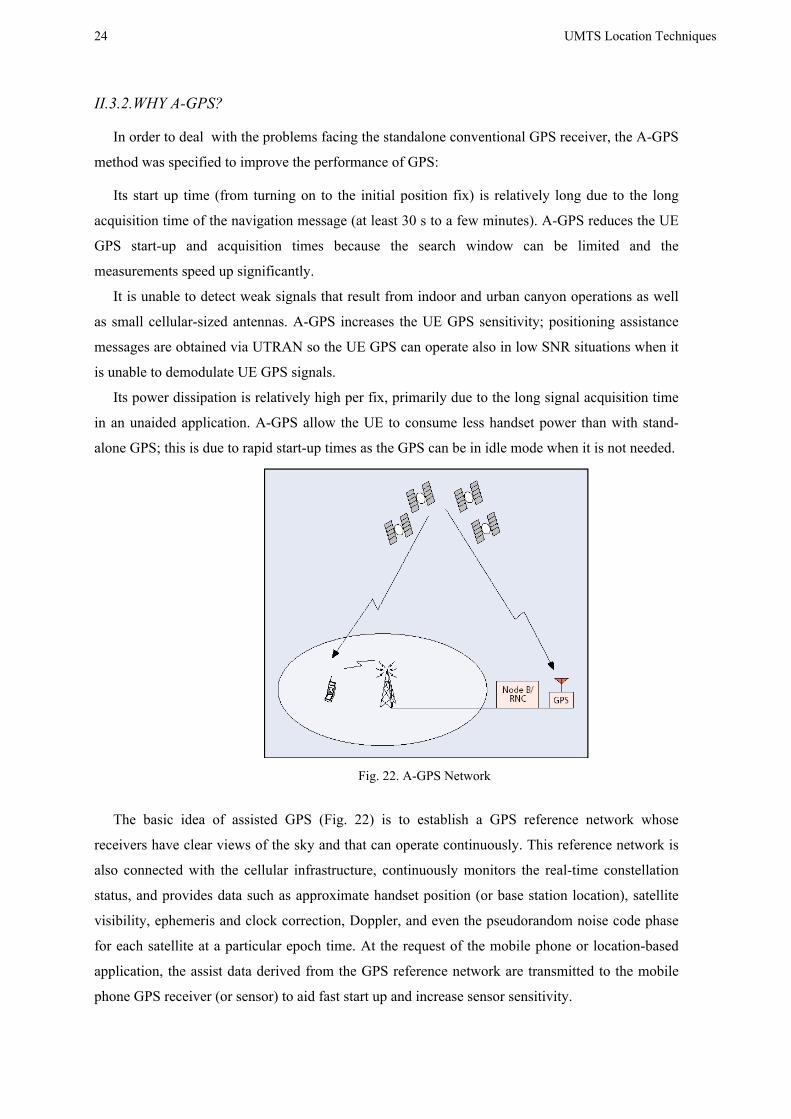
Fig. 22. A-GPS Network
The basic idea of assisted GPS (Fig. 22) is to establish a GPS reference network whose
receivers have clear views of the sky and that can operate continuously. This reference network is
also connected with the cellular infrastructure, continuously monitors the real-time constellation
status, and provides data such as approximate handset position (or base station location), satellite
visibility, ephemeris and clock correction, Doppler, and even the pseudorandom noise code phase
for each satellite at a particular epoch time. At the request of the mobile phone or location-based
application, the assist data derived from the GPS reference network are transmitted to the mobile
phone GPS receiver (or sensor) to aid fast start up and increase sensor sensitivity.
UMTS Location Techniques
25
As in the case of O-TDOA, there are two solutions for A-GPS. A UE can support either one or
both of them:
• The UE-assisted solution shifts the majority of the traditional GPS receiver functions to
the network processor. This method requires an antenna, RF section, and digital
processor in the UE for making measurements by generating replica codes and
correlating them with the received GPS signals. The network transmits an assistance
message to the mobile station, consisting of time, visible satellite list, satellite signal
Doppler and code phase, as well as their search windows or, alternatively, approximate
handset position and ephemeris. These IEs help the embedded GPS sensor reduce the
GPS acquisition time. The assistance data of Doppler and code phase are valid for a few
minutes, while ephemeris data last two to four hours. It returns from the UE the
pseudorange data processed by the GPS sensor. After receiving the pseudo-range data,
the location server in the SRNC or SAS estimates the position of the UE. The
differential correction (DGPS) can be applied to the pseudo-range data or final result at
the network side to improve the position accuracy. The essential IEs from UTRAN to
UE are reference UE position, GPS reference time, plus either code phase and Doppler
(acquisition assistance) or satellite positions (ephemeris and clock correction).
• The UE-based solution maintains a fully functional GPS receiver in the handset. This
requires the same functionality described for UE-assisted GPS, plus additional means
for computing the positions of the satellites and ultimately the UE’s position. This
additional handset function generally adds to the handset’s total memory (RAM, ROM)
requirements in addition to extra computing capability such as million instructions per
second (MIPS). In the initial startup scenario, data in the form of the precise satellite
orbital elements (ephemeris) must be provided to the UE. This data is valid for two to
four hours and can be extended to cover the entire visible period of the GPS satellite
(i.e., up to 12 hours). The essential IEs from UTRAN to UE are reference UE position,
GPS reference time, plus satellite positions and failed/ failing satellites information
(real-time integrity). The UE-based method maintains a full GPS receiver functionality
in the UE, and the position calculation is carried out by the UE, thus allowing stand-
alone position fixes. In the UE-assisted method, the UE employs a reduced complexity
GPS receiver functionality.
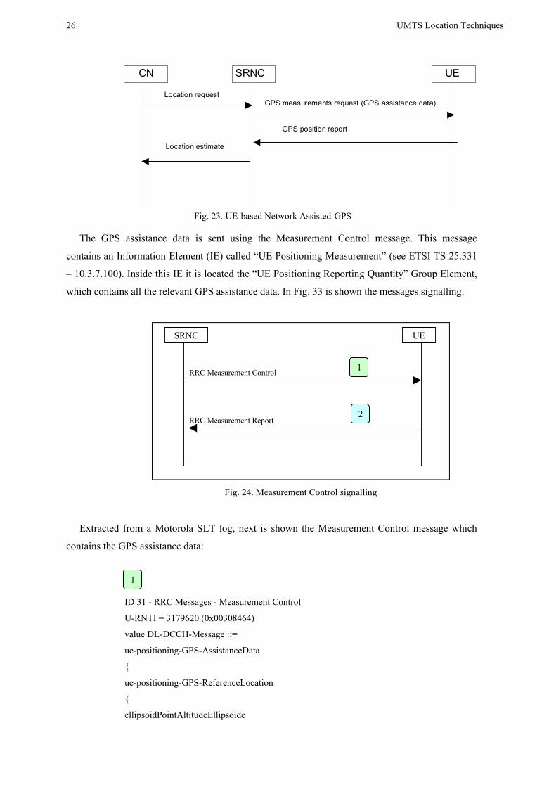
II.3.3. REAL MEASUREMENT REPORT
Next it is shown an example with real measurements of UE-based Network Assisted GPS. In
Fig. 23 it can be observed the procedure.
26 UMTS Location Techniques
UESRNCCN
Location request
GPS position report
Location estimate
GPS measurements request (GPS assistance data)
Fig. 23. UE-based Network Assisted-GPS
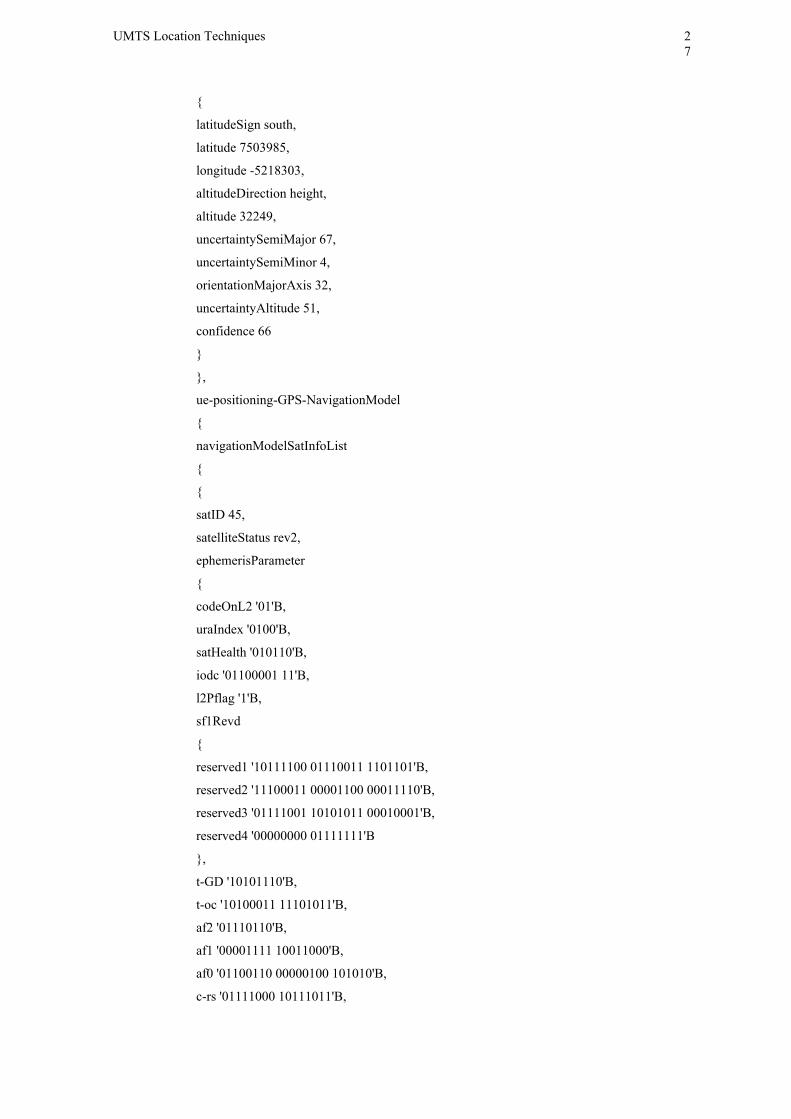
The GPS assistance data is sent using the Measurement Control message. This message
contains an Information Element (IE) called “UE Positioning Measurement” (see ETSI TS 25.331
– 10.3.7.100). Inside this IE it is located the “UE Positioning Reporting Quantity” Group Element,
which contains all the relevant GPS assistance data. In Fig. 33 is shown the messages signalling.
UE SRNC
RRC Measurement Control
RRC Measurement Report
Fig. 24. Measurement Control signalling
Extracted from a Motorola SLT log, next is shown the Measurement Control message which
contains the GPS assistance data:
ID 31 - RRC Messages - Measurement Control
U-RNTI = 3179620 (0x00308464)
value DL-DCCH-Message ::=
ue-positioning-GPS-AssistanceData
{
ue-positioning-GPS-ReferenceLocation
{
ellipsoidPointAltitudeEllipsoide
1
2
1
UMTS Location Techniques
27
{
latitudeSign south,
latitude 7503985,
longitude -5218303,
altitudeDirection height,
altitude 32249,
uncertaintySemiMajor 67,
uncertaintySemiMinor 4,
orientationMajorAxis 32,
uncertaintyAltitude 51,
confidence 66
}
},
ue-positioning-GPS-NavigationModel
{
navigationModelSatInfoList
{
{
satID 45,
satelliteStatus rev2,
ephemerisParameter
{
codeOnL2 '01'B,
uraIndex '0100'B,
satHealth '010110'B,
iodc '01100001 11'B,
l2Pflag '1'B,
sf1Revd
{
reserved1 '10111100 01110011 1101101'B,
reserved2 '11100011 00001100 00011110'B,
reserved3 '01111001 10101011 00010001'B,
reserved4 '00000000 01111111'B
},
t-GD '10101110'B,
t-oc '10100011 11101011'B,
af2 '01110110'B,
af1 '00001111 10011000'B,
af0 '01100110 00000100 101010'B,
c-rs '01111000 10111011'B,
28 UMTS Location Techniques
delta-n '10111111 10000011'B,
m0 '10010011 10000001 11000101 01000001'B,
c-uc '00010100 10001001'B,
e '01001010 01010000 10000111 00001111'B,
c-us '10000010 00101011'B,
a-Sqrt '00010001 00111110 00000000 00010111'B,
t-oe '01001011 10011011'B,
fitInterval '0'B,
aodo '01101'B,
c-ic '01100010 00000000'B,
omega0 '00110101 00010011 10000000 01010011'B,
c-is '01000111 00001100'B,
i0 '11111101 11111111 01001000 11101000'B,
c-rc '01001100 01111111'B,
omega '11010100 00111101 01111000 01010101'B,
omegaDot '00010000 00100010 00000010'B,
iDot '00010100 100010'B
}
ID 32 - RRC Messages - Measurement Report
U-RNTI = 3179620 (0x00308464)
value UL-DCCH-Message ::=
{
message measurementReport :
{
measurementIdentity 8,
measuredResults ue-positioning-MeasuredResults :
{
ue-positioning-PositionEstimateInfo
{
modeSpecificInfo fdd :
{
referenceIdentity
{
primaryScramblingCode 148
}},
referenceSFN 1315,
gps-tow-rem-usec 692,
positionEstimate ellipsoidPointUncertCircle :
2
UMTS Location Techniques
29
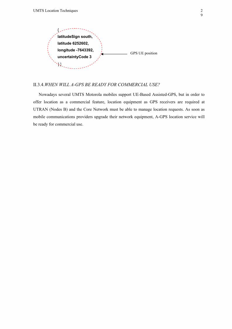
{
latitudeSign south, latitude 6252602, longitude -7643392, uncertaintyCode 3
}}
II.3.4. WHEN WILL A-GPS BE READY FOR COMMERCIAL USE?
Nowadays several UMTS Motorola mobiles support UE-Based Assisted-GPS, but in order to
offer location as a commercial feature, location equipment as GPS receivers are required at
UTRAN (Nodes B) and the Core Network must be able to manage location requests. As soon as
mobile communications providers upgrade their network equipment, A-GPS location service will
be ready for commercial use.
GPS UE position
30 UMTS Location Techniques
III. CONCLUSIONS Several location techniques have been presented in this document. Most of them are techniques
which take advantage of the provided parameters by UTRAN.
Two main research lines remain opened nowadays, location using time parameters and location
using power parameters. This document has been focused on time parameters, those provided by
the 3GPP standard in captured RRC messages.
The standardized RACH Propagation Delay parameter offers a ± 2 chips accuracy what it is
directly translated into a 312.5 metres of uncertainty. This accuracy has been validated and it is
accomplished in most cases but the dispersion of values is not good enough for enabling user
location services at the moment. Up to 1.258 real voice and data calls have been analyzed from real
trial networks. It is remarkable the fact that most of them have been carried out in urban or dense
urban environments where the UE usually remains at the initial position but the dispersion and
multipath channel effects are higher.
In order to improve the RACH Propagation Delay reported value, some radio parameters like
Ec/No, RSSI, RSCP and speed have been studied. None of them have improved error enough for
allowing user service location but all of them are useful for accomplishing the aim of the RACH
Propagation Delay parameter: the Radio Resource Management (RRM).
UTRAN Radio Resource Management systems can be feed with the RACH Propagation Delay
in order to establish hot spot locations and manage radio resources in a better way. On the other
hand, network optimization tools can use the results provided by this technique, which offers a
zero cost of implementation.
A movement UE tracker using the RAKE receiver at the Node B was proposed. This technique
could be implemented in conjunction with the RACH Propagation Delay which would estimate the
initial distance to the BS. Next, the finger searcher would track the UE movement along the cell.
The obtained mean error depends on the movement. It is necessary to complete the presented study
with more measurements at different speeds in order to evaluate how the error varies with the
distance to the initial position.
Finally, it was presented a short overview about the Assisted GPS technique for locating UEs.
This is the only technique suitable for commercial use because its precision is higher enough to.
For the UE-based A-GPS a log was available and was shown the information provided by UTRAN
in the Measurement Control to the UE, and the reported GPS position from the UE to the BS in the
Measurement report message.
UMTS Location Techniques
31
ABBREVIATIONS BS Base Station
CN Core Network
DL Down Link
FDD Frequency Division Duplex
GPS Global Positioning System
HO Handover
L1 Layer 1
L2 Layer 2
MAC Medium Access Control
RAB Radio Access Bearer
RACH Random Access Channel
RAN Radio Access Network
RL Radio Link
RNC Radio Network Controller
RNS Radio Network Subsystem
RRC Radio Resource Control
RRM Radio Resource Management
SIR Signal to Interference ratio
SRNC Serving RNC
SRNS Serving RNS
TDD Time Division Duplex
TOA Time Of Arrival
UE User Equipment
UL Up-Link
UTRAN UMTS Terrestrial Radio Access Network

32 UMTS Location Techniques
ACKNOWLEDGEMENTS This work has been supported by Motorola Inc. and the Institute of Telecommunications and Multimedia Applications (iTEAM) of the Technical University of Valencia. In addition, I would like to express my gratitude to Prof. Narcís Cardona who gave me his support during the researcher stage of my life.
UMTS Location Techniques
33
REFERENCES [1] 3GPP TS 25.215 v4.7.0 (2003-06). 3rd Generation Partnership Project; Technical Specification Group
Radio Access Network; “Physical Layer – Measurements (FDD)” [2] 3GPP TS 25.133 v.4.7.0 (2002-12). 3rd Generation Partnership Project; Technical Specification Group
Radio Access Network; “Requirements for support of radio resource management (FDD)” [3] 3GPP TS 25.305 v.6.0.0 (2003-12). 3rd Generation Partnership Project; Technical Specification Group
Radio Access Network; “Stage 2 functional specification of User Equipment (UE) positioning in UTRAN”
[4] 3GPP TS 22.071 v.6.7.0 (2004-03). 3rd Generation Partnership Project; Technical Specification Group Services and System Aspects; “Location Services (LCS); Service description; Stage 1”
[5] 3GPP TS 23.271 v.6.7.0 (2004-03). 3rd Generation Partnership Project; Technical Specification Group Services and System Aspects; “Functional stage 2 description of Location Services (LCS)”.
[6] Yilin Zhao, Motorola Inc. “Standarization of Mobile Phone Positioning for 3G Systems” Standard Reports, IEEE Communications Magazine, July 2002.

34 UMTS Location Techniques
ANNEXE Published papers included: • Argilés Ortiz, David; Soler Ruiz, Vicente Ramón; Cardona Marcet, Narcis.”UE Distance Estimation
technique using the RACH Propagation Delay on UMTS Networks”; Wireless Personal Mobile Communications 2005 (WPMC’05) ; I.S.B.N.: 87-90834-79-8 ; Aalborg (Dinamarca)
• Argilés Ortiz, David; Soler Ruiz, Vicente Ramón; Fernández,J.M.; Rubio Arjona,
Lorenzo;”Localización de terminales móviles en redes UMTS mediante parámetros de la UTRAN”; XX Simposium Nacional de la Unión Científica Internacional de Radio URSI 2005; I.S.B.N.: 84-9705-859-3; Gandia (España)
UE Distance Estimation technique using the RACH Propagation Delay on UMTS Networks
David Argilés, Vicente Soler, J.M. Fernández, Narcís Cardona
Institute of Telecommunications & Multimedia Applications (iTEAM) Mobile Communications Group, Technical University of Valencia (UPV)
Camino de Vera s/n, Valencia, Spain [email protected] ; [email protected] ; [email protected] ; [email protected]
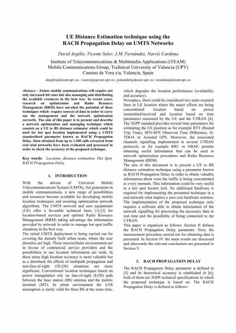
Abstract— Future mobile communications will require not only increased bit rates but also managing and distributing the available resources in the best way. In recent years, research on optimization and Radio Resource Management (RRM) have unveiled the potential of these techniques which require sources of data in order to carry out the management and the network optimization correctly. The aim of this paper is to present and describe a network optimization and managing technique which consists on a UE to BS distance estimator which could be used for hot spot location implemented using a UMTS standardized parameter known as RACH Propagation Delay. Data obtained from up to 1.300 calls extracted from real trial networks have been evaluated and processed in order to check the accuracy of the proposed technique. Key words: Location, distance estimation, Hot Spot, RACH Propagation Delay
1. INTRODUCTION
With the advent of Universal Mobile Telecommunications System (UMTS), 3rd generation in mobile communications, a new range of possibilities and resources become available for developing mobile location techniques and assisting optimization network algorithms. The UMTS network and user equipments (UE) offer a favorable technical basis [1]-[3] for location-based services and optimal Radio Resource Management (RRM) taking advantage the information provided by network in order to manage hot spot traffic situations in the best way. The initial UMTS deployment is being carried out for covering the densely built urban areas, where the user densities are high. These microcellular environments are in favour of commercial service providers and the possibilities to use location information are wide. In these areas high location accuracy is more valuable but as a drawback the effects of multipath propagation and non-line-of-sight (NLOS) situations are more significant. Conventional location techniques based on power triangulation rely on line-of-sight (LOS) path between the base station (BS) antenna and the mobile terminal (MT). In urban environment the LOS assumption is rarely valid for three BS at the same time,
which degrades the location performance (availability and accuracy). Nowadays, there could be considered two main research lines in UE location where the major efforts are being concentrated: location based on power transmitted/received and location based on time parameters measured by the UE and the UTRAN [4]. The 3GPP standard provides several time parameters for estimating the UE position as for example RTT (Round Trip Time), SFN-SFN Observed Time Difference, O-TDOA or Assisted GPS. Moreover, the associated channels signalling implemented in several UTRAN protocols, as for example RRC or NBAP, permits obtaining useful information that can be used in network optimization procedures and Radio Resource Management (RRM). The aim of this document is to present a UE to BS distance estimation technique using a parameter known as RACH Propagation Delay in order to obtain valuable information about were the traffic is being concentrated at every moment. This information could be very useful in a hot spot locator tool. No additional hardware is required for implementing the presented technique in a real network what implies a zero cost hardware solution. The implementation of the proposed technique only requires a software able to obtain information of the network signalling for processing the necessary data in real time and the possibility of being connected to the UTRAN. This paper is organised as follows. Section II defines the RACH Propagation Delay parameter. Next, the measurement procedure carried out for obtaining data is presented. In Section IV the main results are discussed and afterwards the relevant conclusions are presented in Section V.
2. RACH PROPAGATION DELAY
The RACH Propagation Delay parameter is defined in [5] and its theoretical accuracy is established in [6]; both of them are 3GPP technical specifications in which the proposed technique is based on. The RACH Propagation Delay is defined as follows:

2560Pr2
RX TXT TopagationDelay − −= (1)
where:
TTX is the transmission time of AICH access slot (n-2-AICH transmission timing), where:
o 0 ≤ (n-2-AICH Transmission Timing) ≤ 14
o AICH_Transmission_Timing is valued 0 or 1
TRX is the time of reception of the beginning (the first detected path, in time) of the PRACH message from the UE at PRACH access slot n.
The theoretical accuracy provided by the RACH
Propagation Delay is ± 2 chip. It is remarkable the fact that the RACH Propagation Delay is not available during the call because it is only measured when the call sets up. Because of this, the proposed technique is only possible to be used to locate users at moment of the call set up. It is important to note that in urban environments users mobility is low and because of this it is possible to assume that high percentage of them will remain static. Complementarily, other available techniques as for example finger information are possible to be used to complete user tracking.
In order to establish a voice or data call in UMTS, the first step to be completed is to establish a RRC Connection in order to create a Dedicated Control Channel (DCCH) between UE and SRNC. The RACH Propagation Delay is a parameter sent during the RRC Connection establishment procedure. In Figure 1 it can be observed the message flow between the Serving RNC, Node B and UE for establishing a RRC Connection.
UE Node
B SRNC
RRC RRCRRC Connection Request (CCCH:RACH)
NBAPNBAP Radio Link Setup Request
NBAP NBAPRadio Link Setup Response
DCP Radio Link Setup Request
RRCRRC RRC Connection Setup (CCCH:FACH)
RRC RRCRRC Connection Setup Complete (DCCH:DCH)
Figure 1. RRC Connection establishment message flow
The RACH Propagation Delay, provided in chip units, is reported in the Radio Link Setup Request, a message that can be extracted using a protocol analyzer or a logging tool as for example Motorola SLT.
3. EVALUATION PROCEDURE
In order to evaluate the accuracy of the proposed technique up to 1.258 real voice and data calls have been traced for computing the obtained results. Real data obtained from trial networks have been used, most of them in urban or dense urban environment. The GPS positions of the test UEs and the target Base Stations (BS) are available in all the traced calls for computing the associated error between the RACH Propagation Delay estimation and the exact GPS position at the beginning of the call. It can be observed in Figure 2 the followed evaluation procedure for collecting, processing data and finally calculate the distance error estimation.
TEMS drive test Motorola SLT
UTRANUu
Synchronization
Link to RNC and Node B
GPS Position
Radio Link Setup
Request
RACH PD extraction
UE-BS distance calculation
Error calculation
TEMS drive test Motorola SLT
UTRANUu
Synchronization
Link to RNC and Node B
GPS Position
Radio Link Setup
Request
RACH PD extraction
UE-BS distance calculation
Error calculation Figure 2. Evaluation procedure
As depicted in Figure 2, information from both sources of data, TEMS and Motorola SLT, are available for comparing the RACH Propagation Delay position estimation and the GPS data. The accuracy evaluation procedure consists on comparing the exact GPS position logged with TEMS WCDMA and the obtained value of the RACH Propagation Delay parameter at the moment of stetting up the call. Data must be synchronized before because master clocks are different. Motorola SLT takes its master clock from the UTRAN and TEMS takes it from the drive test laptop. The next step is to obtain the RACH Propagation Delay value which can be directly extracted from the corresponding NBAP signalling message called Radio Link Setup Request. Finally, the reported RACH Propagation Delay UE to BS distance is calculated and compared with the GPS position in order to obtain the error estimation. It is important to note that 1 chip corresponds to 78.125 metres of distance. The full process was automated applying PERL scripts to TEMS and Motorola SLT logs.
4. RESULTS
The aim of the complete study is to evaluate the UE to BS distance error reported by the RACH Propagation Delay and to determine how the chip error of the reported distance by the RACH Propagation Delay could be corrected or assisted with the CPICH Ec/No ratio, Received Signal Code Power (RSCP), Received Strength Signal (RSSI) and speed.
4.1. Error histogram and chip error distribution
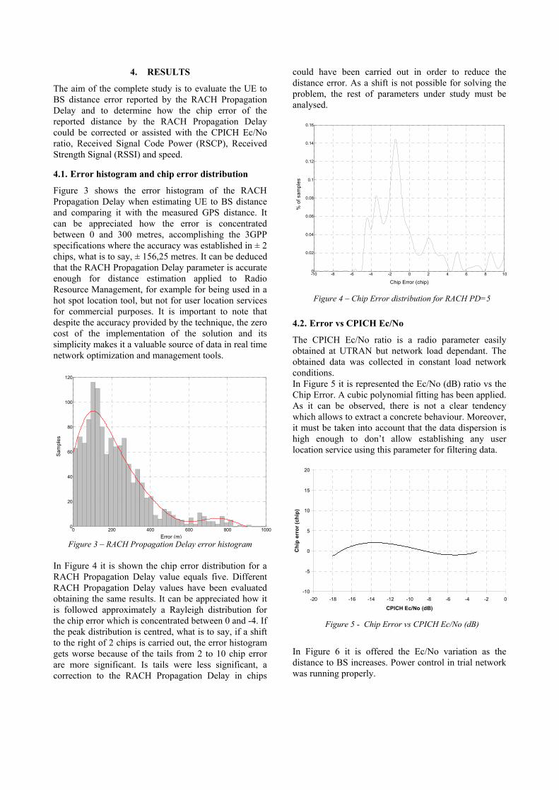
Figure 3 shows the error histogram of the RACH Propagation Delay when estimating UE to BS distance and comparing it with the measured GPS distance. It can be appreciated how the error is concentrated between 0 and 300 metres, accomplishing the 3GPP specifications where the accuracy was established in ± 2 chips, what is to say, ± 156,25 metres. It can be deduced that the RACH Propagation Delay parameter is accurate enough for distance estimation applied to Radio Resource Management, for example for being used in a hot spot location tool, but not for user location services for commercial purposes. It is important to note that despite the accuracy provided by the technique, the zero cost of the implementation of the solution and its simplicity makes it a valuable source of data in real time network optimization and management tools.
0 200 400 600 800 10000
20
40
60
80
100
120
Error (m)
Sam
ples
Figure 3 – RACH Propagation Delay error histogram
In Figure 4 it is shown the chip error distribution for a RACH Propagation Delay value equals five. Different RACH Propagation Delay values have been evaluated obtaining the same results. It can be appreciated how it is followed approximately a Rayleigh distribution for the chip error which is concentrated between 0 and -4. If the peak distribution is centred, what is to say, if a shift to the right of 2 chips is carried out, the error histogram gets worse because of the tails from 2 to 10 chip error are more significant. Is tails were less significant, a correction to the RACH Propagation Delay in chips
could have been carried out in order to reduce the distance error. As a shift is not possible for solving the problem, the rest of parameters under study must be analysed.
-10 -8 -6 -4 -2 0 2 4 6 8 100
0.02
0.04
0.06
0.08
0.1
0.12
0.14
0.16
Chip Error (chip)
% o
f sam
ples
Figure 4 – Chip Error distribution for RACH PD=5
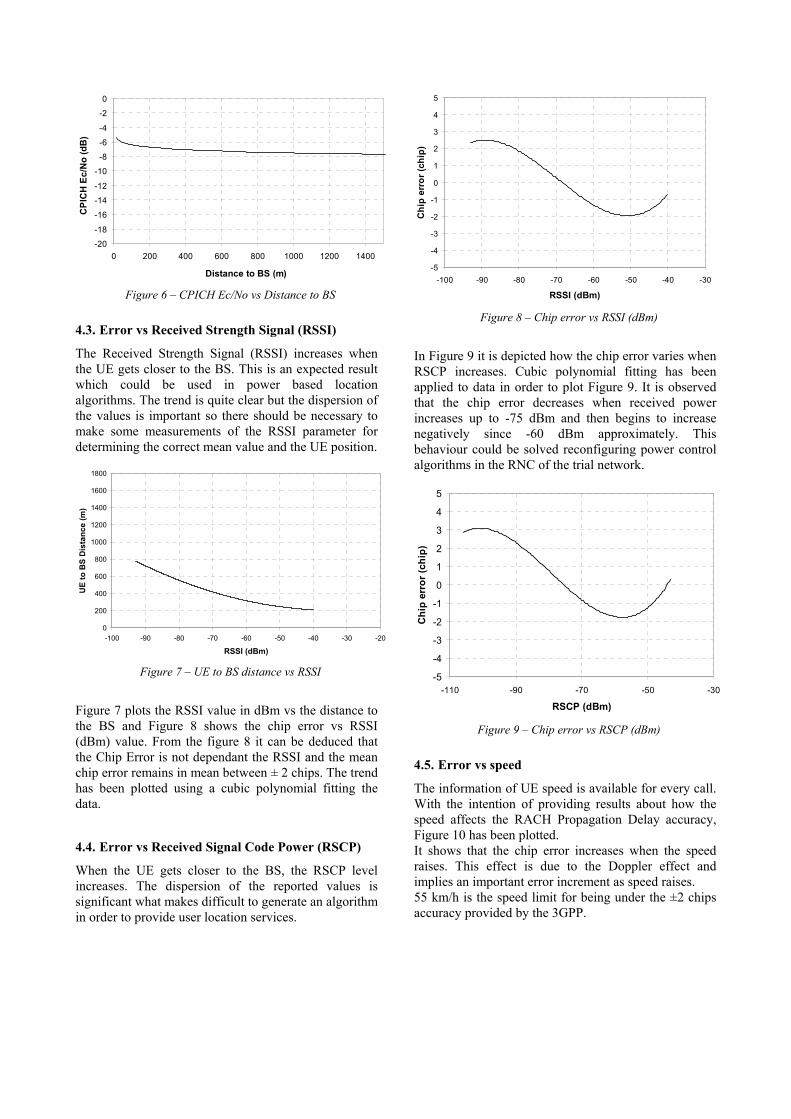
4.2. Error vs CPICH Ec/No
The CPICH Ec/No ratio is a radio parameter easily obtained at UTRAN but network load dependant. The obtained data was collected in constant load network conditions. In Figure 5 it is represented the Ec/No (dB) ratio vs the Chip Error. A cubic polynomial fitting has been applied. As it can be observed, there is not a clear tendency which allows to extract a concrete behaviour. Moreover, it must be taken into account that the data dispersion is high enough to don’t allow establishing any user location service using this parameter for filtering data.
-10
-5
0
5
10
15
20
-20 -18 -16 -14 -12 -10 -8 -6 -4 -2 0
CPICH Ec/No (dB)
Chi
p er
ror (
chip
)
Figure 5 - Chip Error vs CPICH Ec/No (dB)
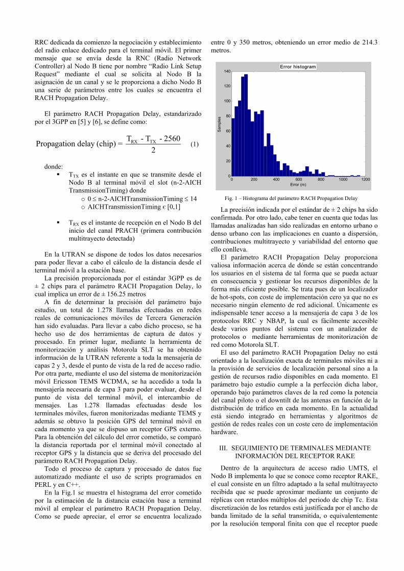
In Figure 6 it is offered the Ec/No variation as the distance to BS increases. Power control in trial network was running properly.
-20
-18
-16
-14
-12
-10
-8
-6
-4
-2
0
0 200 400 600 800 1000 1200 1400
Distance to BS (m)
CPI
CH
Ec/
No
(dB
)
Figure 6 – CPICH Ec/No vs Distance to BS
4.3. Error vs Received Strength Signal (RSSI)
The Received Strength Signal (RSSI) increases when the UE gets closer to the BS. This is an expected result which could be used in power based location algorithms. The trend is quite clear but the dispersion of the values is important so there should be necessary to make some measurements of the RSSI parameter for determining the correct mean value and the UE position.
0
200
400
600
800
1000
1200
1400
1600
1800
-100 -90 -80 -70 -60 -50 -40 -30 -20
RSSI (dBm)
UE
to B
S D
ista
nce
(m)
Figure 7 – UE to BS distance vs RSSI
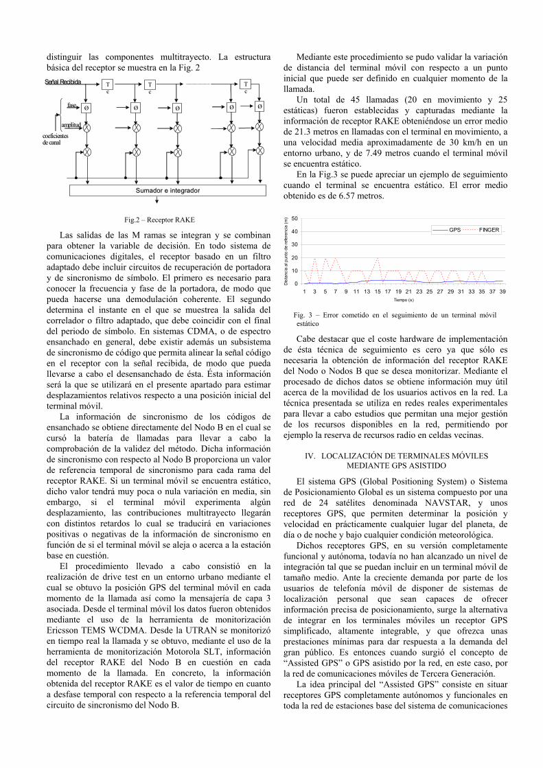
Figure 7 plots the RSSI value in dBm vs the distance to the BS and Figure 8 shows the chip error vs RSSI (dBm) value. From the figure 8 it can be deduced that the Chip Error is not dependant the RSSI and the mean chip error remains in mean between ± 2 chips. The trend has been plotted using a cubic polynomial fitting the data.
4.4. Error vs Received Signal Code Power (RSCP)
When the UE gets closer to the BS, the RSCP level increases. The dispersion of the reported values is significant what makes difficult to generate an algorithm in order to provide user location services.
-5
-4
-3
-2
-1
0
1
2
3
4
5
-100 -90 -80 -70 -60 -50 -40 -30
RSSI (dBm)
Chi
p er
ror (
chip
)
Figure 8 – Chip error vs RSSI (dBm)
In Figure 9 it is depicted how the chip error varies when RSCP increases. Cubic polynomial fitting has been applied to data in order to plot Figure 9. It is observed that the chip error decreases when received power increases up to -75 dBm and then begins to increase negatively since -60 dBm approximately. This behaviour could be solved reconfiguring power control algorithms in the RNC of the trial network.
-5
-4
-3
-2
-1
0
1
2
3
4
5
-110 -90 -70 -50 -30
RSCP (dBm)
Chi
p er
ror (
chip
)
Figure 9 – Chip error vs RSCP (dBm)
4.5. Error vs speed
The information of UE speed is available for every call. With the intention of providing results about how the speed affects the RACH Propagation Delay accuracy, Figure 10 has been plotted. It shows that the chip error increases when the speed raises. This effect is due to the Doppler effect and implies an important error increment as speed raises. 55 km/h is the speed limit for being under the ±2 chips accuracy provided by the 3GPP.

-5
-4
-3
-2
-1
0
1
2
3
4
5
0 10 20 30 40 50 60 70
Speed (km/h)
Chi
p er
ror (
chip
)
Figure 10 – Chip error vs speed
5. CONCLUDING REMARKS
The standardised RACH Propagation Delay parameter offers a ± 2 chips accuracy what it is directly translated into a 312.5 metres of uncertainty. This accuracy has been validated and it is accomplished in most cases as reflected in section 4 but the dispersion of values is not good enough for enabling user location services at the moment. Up to 1.258 real voice and data calls have been analyzed from real trial networks. It is remarkable the fact that most of them have been carried out in urban or dense urban environments where the UE usually remains at the initial position but the dispersion and multipath channel effects are higher. In order to improve the RACH Propagation Delay reported value, some radio parameters as CPICH Ec/No, RSSI, RSCP and speed have been studied. None of them have improved error enough for allowing user service location but all of the are useful for accomplishing the aim of the RACH Propagation Delay parameter which is the Radio Resource Management (RRM). The RSSI an RSCP parameters could be useful when locating UEs by using power based algorithms. The accuracy provided by RSCP is good enough for hot spot location. The Ec/No parameter is available at UTRAN but it is not recommended to be used for power based location because it is dependant of the cell load.
It is remarkable the fact that the RACH Propagation Delay is a parameter that is only available when the call sets up and not during the call. This parameter provides an initial circumference over the cell, a distance to the base station, but complementary location techniques as power based triangulation, finger tracking, SFN-SFN observed time difference or Round Trip Time (RTT) should be applied in order to determine a fixed UE position. UTRAN Radio Resource Management systems can be feed with the RACH Propagation Delay in order to establish hot spot locations and manage radio resources in a better way. On the other hand, network optimization tools can use the results provided by this technique, which offers a zero cost hardware implementation.
ACKNOWLEDGMENT
This work has been supported by Motorola Inc. and the Institute for Telecommunications and Multimedia Applications (iTEAM) at the Technical University of Valencia.
REFERENCES
[1] 3GPP TS 25.305 v.6.0.0 (2003-12). 3rd Generation Partnership Project; Technical Specification Group Radio Access Network; “Stage 2 functional specification of User Equipment (UE) positioning in UTRAN”
[2] 3GPP TS 22.071 v.6.7.0 (2004-03). 3rd Generation Partnership Project; Technical Specification Group Services and System Aspects; “Location Services (LCS); Service description; Stage 1”
[3] 3GPP TS 23.271 v.6.7.0 (2004-03). 3rd Generation Partnership Project; Technical Specification Group Services and System Aspects; “Functional stage 2 description of Location Services (LCS)”.
[4] Yilin Zhao, Motorola Inc. “Standarization of Mobile Phone Positioning for 3G Systems” Standard Reports, IEEE Communications Magazine, July 2002.
[5] 3GPP TS 25.215 v4.7.0 (2003-06). 3rd Generation Partnership Project; Technical Specification Group Radio Access Network; “Physical Layer – Measurements (FDD)”
[6] 3GPP TS 25.133 v.4.7.0 (2002-12). 3rd Generation Partnership Project; Technical Specification Group Radio Access Network; “Requirements for support of radio resource management (FDD)”

Localización de terminales móviles en redes UMTS mediante parámetros de la UTRAN
D.Argilés, V.Soler, J.Fernández, J.F.Monserrat, L.Rubio Departamento de Comunicaciones
Instituto de Telecomunicaciones y Aplicaciones Multimedia (iTEAM) Universidad Politécnica de Valencia
e-mail : [email protected],[email protected], [email protected],[email protected],[email protected]
Abstract- Future mobile communications will require not only increased bit rates but also managing and distributing the available resources in the best way. In recent years, research on optimization and Radio Resource Management (RRM) have unveiled the potential of these techniques which require sources of data in order to carry out the management and the network optimization properly. The aim of this paper is to present and describe three network optimization and managing tools which consists on mobile to BS distance estimation, RAKE fingers movement tracking and Assisted-GPS location based. Data obtained from up to 1.300 calls extracted from real trial networks have been evaluated in order to check out the accuracy of the proposed techniques. Location services applied to improve performance and optimize mobile communication networks will provide a new range of possibilities for Radio Resource Management (RRM).
I. INTRODUCCIÓN
Con la implantación de las redes de comunicaciones móviles de Tercera Generación, Universal Mobile Telecommunications System (UMTS), se abre un nuevo abanico de posibilidades en cuanto al desarrollo de nuevos algoritmos para la gestión eficiente y optimización de recursos radio (Radio Resource Management RRM) [1],[2] y [3]. Con el fin de llevar a cabo dicha gestión de recursos se hace imprescindible disponer de fuentes de información que permitan localizar los recursos y usuarios de la red en cada momento a fin de distribuir y gestionar los recursos disponibles maximizando la capacidad de la red. La red de acceso radio (UTRAN) UMTS, mediante su mensajería asociada de capa 3 en sus correspondientes protocolos RRC y NBAP, proporciona un conjunto de parámetros que permiten a los operadores disponer de una de las herramientas más potentes y versátiles para gestionar sus recursos como es la localización de los usuarios en la red en tiempo real. Tanto las redes de comunicaciones móviles UMTS como los terminales móviles ofrecen una disposición favorable para el desarrollo de técnicas y servicios de localización.
En la actualidad, existen dos líneas principales de investigación en cuanto a localización de terminales móviles se refiere: localización en base a parámetros de potencia y
localización en base a parámetros de tiempo proporcionados por la UTRAN.
El presente artículo se centra en la segunda línea de investigación, localización de terminales móviles en base a parámetros de tiempo [4]. El estándar de comunicaciones móviles de Tercera Generación (3GPP) proporciona varios parámetros temporales en base a los cuales es posible determinar, con un cierto error que a lo largo del artículo se acotará, la distancia desde el terminal móvil a la estación base así como el movimiento relativo experimentado por el terminal móvil desde un punto de referencia fijado. Algunos de estos parámetros son el Round Trip Time(RTT), SFN-SFN Observed Time Difference, RACH Propagation Delay, seguimiento mediante información de contribuciones multitrayecto del receptor RAKE y GPS asistido.
Los tres últimos parámetros mencionados serán objeto de estudio en el presente artículo el cual se organiza de la siguiente manera: en la sección II se describirá el parámetro RACH Propagation Delay y se ofrecerán resultados obtenidos en redes reales de comunicaciones móviles con una muestra de aproximadamente 1.300 llamadas de voz y datos. La sección III describe el método de seguimiento de terminales móviles en base a información extraída directamente del receptor RAKE ubicado en un Nodo B real, ofreciendo datos de desplazamientos relativos respecto a una posición inicial fijada. El apartado IV está dedicado a una técnica de localización precisa conocida como GPS asistido la cual hace uso del sistema de localización global a fin de simplificar el receptor GPS integrado en el terminal móvil. Finalmente, en el apartado V se ofrecen las conclusiones y perspectivas de futuro en cuanto a sistema de localización tanto orientados a gestión de recursos como para uso personal.
II. RACH PROPAGATION DELAY
El objetivo del presente apartado es el de presentar un estimador de distancia entre la estación base y el terminal móvil mediante el uso de un parámetro proporcionado por la UTRAN cuyo nombre es RACH Propagation Delay.
El procedimiento de red para establecer una llamada, ya sea de voz o de datos, incluye una fase de establecimiento de la conexión así como una negociación de parámetros de calidad de servicio asociada y de características del enlace. Dentro del protocolo NBAP, mediante el cual se gestionan los recursos radio disponibles en la red, y en este caso en particular en el NodoB, después de establecer una conexión
RRC dedicada da comienzo la negociación y establecimiento del radio enlace dedicado para el terminal móvil. El primer mensaje que se envía desde la RNC (Radio Network Controller) al Nodo B tiene por nombre “Radio Link Setup Request” mediante el cual se solicita al Nodo B la asignación de un canal y se le proporciona a dicho Nodo B una serie de parámetros entre los cuales se encuentra el RACH Propagation Delay.
El parámetro RACH Propagation Delay, estandarizado
por el 3GPP en [5] y [6], se define como:
RX TXT - T - 2560Propagation delay (chip) = 2
(1)
donde:
TTX es el instante en que se transmite desde el Nodo B al terminal móvil el slot (n-2-AICH TransmissionTiming) donde
o 0 ≤ n-2-AICHTransmissionTiming ≤ 14 o AICHTransmissionTiming є [0,1]
TRX es el instante de recepción en el Nodo B del inicio del canal PRACH (primera contribución multitrayecto detectada)
En la UTRAN se dispone de todos los datos necesarios
para poder llevar a cabo el cálculo de la distancia desde el terminal móvil a la estación base.
La precisión proporcionada por el estándar 3GPP es de ± 2 chips para el parámetro RACH Propagation Delay, lo cual implica un error de ± 156.25 metros
A fin de determinar la precisión del parámetro bajo estudio, un total de 1.278 llamadas efectuadas en redes reales de comunicaciones móviles de Tercera Generación han sido evaluadas. Para llevar a cabo dicho proceso, se ha hecho uso de dos herramientas de captura de datos y procesado. En primer lugar, mediante la herramienta de monitorización y análisis Motorola SLT se ha obtenido información de la UTRAN referente a toda la mensajería de capas 2 y 3, desde el punto de vista de la red de acceso radio. Por otra parte, mediante el uso del sistema de monitorización móvil Ericsson TEMS WCDMA, se ha accedido a toda la mensajería necesaria de capa 3 para poder evaluar, desde el punto de vista del terminal móvil, el intercambio de mensajes. Las 1.278 llamadas efectuadas desde los terminales móviles, fueron monitorizadas mediante TEMS y además se obtuvo la posición GPS del terminal móvil en cada momento ya que se dispuso un receptor GPS externo. Para la obtención del cálculo del error cometido, se comparó la distancia reportada por el terminal móvil conectado al receptor GPS y la distancia que se deriva del procesado del parámetro RACH Propagation Delay.
Todo el proceso de captura y procesado de datos fue automatizado mediante el uso de scripts programados en PERL y en C++.
En la Fig.1 se muestra el histograma del error cometido por la estimación de la distancia estación base a terminal móvil al emplear el parámetro RACH Propagation Delay. Como se puede apreciar, el error se encuentra localizado
entre 0 y 350 metros, obteniendo un error medio de 214.3 metros.
0 200 400 600 800 1000 12000
20
40
60
80
100
120
140
Error (m)
Sam
ples
Error histogram
Fig. 1 – Histograma del parámetro RACH Propagation Delay
La precisión indicada por el estándar de ± 2 chips ha sido confirmada. Por otro lado, cabe tener en cuenta que todas las llamadas analizadas han sido realizadas en entorno urbano o denso urbano con las implicaciones en cuanto a dispersión, contribuciones multitrayecto y variabilidad del entorno que ello conlleva.
El parámetro RACH Propagation Delay proporciona valiosa información acerca de dónde se están concentrando los usuarios en el sistema de tal forma que se pueda actuar en consecuencia y gestionar los recursos disponibles de la forma más eficiente posible. Se trata pues de un localizador de hot-spots, con coste de implementación cero ya que no es necesario ningún elemento de red adicional. Únicamente es indispensable tener acceso a la mensajería de capa 3 de los protocolos RRC y NBAP, la cual es fácilmente accesible desde varios puntos del sistema con un analizador de protocolos o mediante herramientas de monitorización de red como Motorola SLT.
El uso del parámetro RACH Propagation Delay no está orientado a la localización exacta de terminales móviles ni a la provisión de servicios de localización personal sino a la gestión de recursos radio disponibles en cada momento. El parámetro bajo estudio cumple a la perfección dicha labor, operando bajo parámetros claves de la red como la potencia del canal piloto o el downtilt de las antenas en función de la distribución de tráfico en cada momento. En la actualidad está siendo integrado en herramientas y algoritmos de gestión de redes reales con un coste cero de implementación hardware.
III. SEGUIMIENTO DE TERMINALES MEDIANTE INFORMACIÓN DEL RECEPTOR RAKE
Dentro de la arquitectura de acceso radio UMTS, el Nodo B implementa lo que se conoce como receptor RAKE, el cual consiste en un filtro adaptado a la señal multitrayecto recibida que se puede aproximar mediante un conjunto de réplicas con retardos múltiplos del periodo de chip Tc. Esta discretización de los retardos está justificada por el ancho de banda limitado de la señal transmitida, o equivalentemente por la resolución temporal finita con que el receptor puede
distinguir las componentes multitrayecto. La estructura básica del receptor se muestra en la Fig. 2
S S u u m m a a d d oorr e e i i n n t t e e g g r r a a d d o o r r
S S e e ñ ñ a a l l R R e e c c i i b b i i d d a a T T c c
T T c c
TTcc
Ø Ø Ø Ø Ø Ø ØØ ØØ f f a a s s e e
a a m m p p l l i i t t u u d d
c c o o e e f f i i c c i i e e n n t t e e s s d d e e c c a a n n a a l l
Fig.2 – Receptor RAKE
Las salidas de las M ramas se integran y se combinan para obtener la variable de decisión. En todo sistema de comunicaciones digitales, el receptor basado en un filtro adaptado debe incluir circuitos de recuperación de portadora y de sincronismo de símbolo. El primero es necesario para conocer la frecuencia y fase de la portadora, de modo que pueda hacerse una demodulación coherente. El segundo determina el instante en el que se muestrea la salida del correlador o filtro adaptado, que debe coincidir con el final del periodo de símbolo. En sistemas CDMA, o de espectro ensanchado en general, debe existir además un subsistema de sincronismo de código que permita alinear la señal código en el receptor con la señal recibida, de modo que pueda llevarse a cabo el desensanchado de ésta. Ésta información será la que se utilizará en el presente apartado para estimar desplazamientos relativos respecto a una posición inicial del terminal móvil.
La información de sincronismo de los códigos de ensanchado se obtiene directamente del Nodo B en el cual se cursó la batería de llamadas para llevar a cabo la comprobación de la validez del método. Dicha información de sincronismo con respecto al Nodo B proporciona un valor de referencia temporal de sincronismo para cada rama del receptor RAKE. Si un terminal móvil se encuentra estático, dicho valor tendrá muy poca o nula variación en media, sin embargo, si el terminal móvil experimenta algún desplazamiento, las contribuciones multitrayecto llegarán con distintos retardos lo cual se traducirá en variaciones positivas o negativas de la información de sincronismo en función de si el terminal móvil se aleja o acerca a la estación base en cuestión.
El procedimiento llevado a cabo consistió en la realización de drive test en un entorno urbano mediante el cual se obtuvo la posición GPS del terminal móvil en cada momento de la llamada así como la mensajería de capa 3 asociada. Desde el terminal móvil los datos fueron obtenidos mediante el uso de la herramienta de monitorización Ericsson TEMS WCDMA. Desde la UTRAN se monitorizó en tiempo real la llamada y se obtuvo, mediante el uso de la herramienta de monitorización Motorola SLT, información del receptor RAKE del Nodo B en cuestión en cada momento de la llamada. En concreto, la información obtenida del receptor RAKE es el valor de tiempo en cuanto a desfase temporal con respecto a la referencia temporal del circuito de sincronismo del Nodo B.
Mediante este procedimiento se pudo validar la variación de distancia del terminal móvil con respecto a un punto inicial que puede ser definido en cualquier momento de la llamada.
Un total de 45 llamadas (20 en movimiento y 25 estáticas) fueron establecidas y capturadas mediante la información de receptor RAKE obteniéndose un error medio de 21.3 metros en llamadas con el terminal en movimiento, a una velocidad media aproximadamente de 30 km/h en un entorno urbano, y de 7.49 metros cuando el terminal móvil se encuentra estático.
En la Fig.3 se puede apreciar un ejemplo de seguimiento cuando el terminal se encuentra estático. El error medio obtenido es de 6.57 metros.
0
10
20
30
40
50
1 3 5 7 9 11 13 15 17 19 21 23 25 27 29 31 33 35 37 39Tiempo (s)
Dis
tanc
ia a
l pun
to d
e re
fere
ncia
(m)
GPS FINGER
Fig. 3 – Error cometido en el seguimiento de un terminal móvil
estático
Cabe destacar que el coste hardware de implementación de ésta técnica de seguimiento es cero ya que sólo es necesaria la obtención de información del receptor RAKE del Nodo o Nodos B que se desea monitorizar. Mediante el procesado de dichos datos se obtiene información muy útil acerca de la movilidad de los usuarios activos en la red. La técnica presentada se utiliza en redes reales experimentales para llevar a cabo estudios que permitan una mejor gestión de los recursos disponibles en la red, permitiendo por ejemplo la reserva de recursos radio en celdas vecinas.
IV. LOCALIZACIÓN DE TERMINALES MÓVILES MEDIANTE GPS ASISTIDO
El sistema GPS (Global Positioning System) o Sistema de Posicionamiento Global es un sistema compuesto por una red de 24 satélites denominada NAVSTAR, y unos receptores GPS, que permiten determinar la posición y velocidad en prácticamente cualquier lugar del planeta, de día o de noche y bajo cualquier condición meteorológica.
Dichos receptores GPS, en su versión completamente funcional y autónoma, todavía no han alcanzado un nivel de integración tal que se puedan incluir en un terminal móvil de tamaño medio. Ante la creciente demanda por parte de los usuarios de telefonía móvil de disponer de sistemas de localización personal que sean capaces de ofrecer información precisa de posicionamiento, surge la alternativa de integrar en los terminales móviles un receptor GPS simplificado, altamente integrable, y que ofrezca unas prestaciones mínimas para dar respuesta a la demanda del gran público. Es entonces cuando surgió el concepto de “Assisted GPS” o GPS asistido por la red, en este caso, por la red de comunicaciones móviles de Tercera Generación.
La idea principal del “Assisted GPS” consiste en situar receptores GPS completamente autónomos y funcionales en toda la red de estaciones base del sistema de comunicaciones
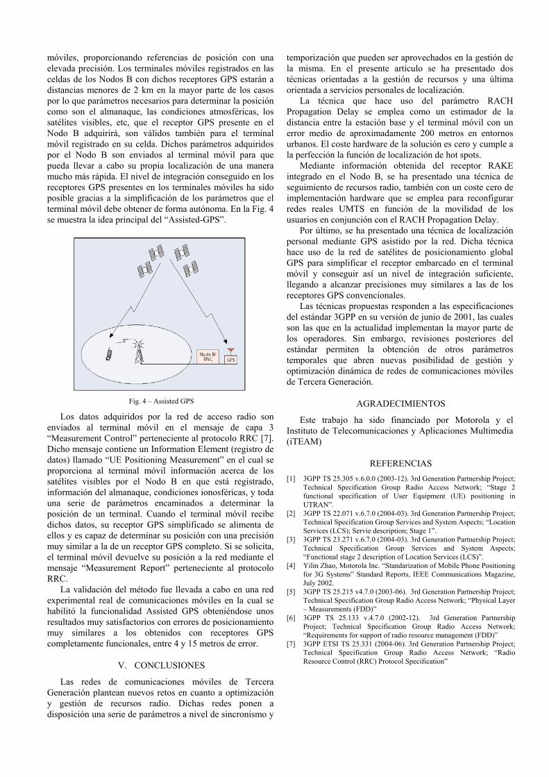
móviles, proporcionando referencias de posición con una elevada precisión. Los terminales móviles registrados en las celdas de los Nodos B con dichos receptores GPS estarán a distancias menores de 2 km en la mayor parte de los casos por lo que parámetros necesarios para determinar la posición como son el almanaque, las condiciones atmosféricas, los satélites visibles, etc, que el receptor GPS presente en el Nodo B adquirirá, son válidos también para el terminal móvil registrado en su celda. Dichos parámetros adquiridos por el Nodo B son enviados al terminal móvil para que pueda llevar a cabo su propia localización de una manera mucho más rápida. El nivel de integración conseguido en los receptores GPS presentes en los terminales móviles ha sido posible gracias a la simplificación de los parámetros que el terminal móvil debe obtener de forma autónoma. En la Fig. 4 se muestra la idea principal del “Assisted-GPS”.
Fig. 4 – Assisted GPS
Los datos adquiridos por la red de acceso radio son enviados al terminal móvil en el mensaje de capa 3 “Measurement Control” perteneciente al protocolo RRC [7]. Dicho mensaje contiene un Information Element (registro de datos) llamado “UE Positioning Measurement” en el cual se proporciona al terminal móvil información acerca de los satélites visibles por el Nodo B en que está registrado, información del almanaque, condiciones ionosféricas, y toda una serie de parámetros encaminados a determinar la posición de un terminal. Cuando el terminal móvil recibe dichos datos, su receptor GPS simplificado se alimenta de ellos y es capaz de determinar su posición con una precisión muy similar a la de un receptor GPS completo. Si se solicita, el terminal móvil devuelve su posición a la red mediante el mensaje “Measurement Report” perteneciente al protocolo RRC.
La validación del método fue llevada a cabo en una red experimental real de comunicaciones móviles en la cual se habilitó la funcionalidad Assisted GPS obteniéndose unos resultados muy satisfactorios con errores de posicionamiento muy similares a los obtenidos con receptores GPS completamente funcionales, entre 4 y 15 metros de error.
V. CONCLUSIONES
Las redes de comunicaciones móviles de Tercera Generación plantean nuevos retos en cuanto a optimización y gestión de recursos radio. Dichas redes ponen a disposición una serie de parámetros a nivel de sincronismo y
temporización que pueden ser aprovechados en la gestión de la misma. En el presente artículo se ha presentado dos técnicas orientadas a la gestión de recursos y una última orientada a servicios personales de localización.
La técnica que hace uso del parámetro RACH Propagation Delay se emplea como un estimador de la distancia entre la estación base y el terminal móvil con un error medio de aproximadamente 200 metros en entornos urbanos. El coste hardware de la solución es cero y cumple a la perfección la función de localización de hot spots.
Mediante información obtenida del receptor RAKE integrado en el Nodo B, se ha presentado una técnica de seguimiento de recursos radio, también con un coste cero de implementación hardware que se emplea para reconfigurar redes reales UMTS en función de la movilidad de los usuarios en conjunción con el RACH Propagation Delay.
Por último, se ha presentado una técnica de localización personal mediante GPS asistido por la red. Dicha técnica hace uso de la red de satélites de posicionamiento global GPS para simplificar el receptor embarcado en el terminal móvil y conseguir así un nivel de integración suficiente, llegando a alcanzar precisiones muy similares a las de los receptores GPS convencionales.
Las técnicas propuestas responden a las especificaciones del estándar 3GPP en su versión de junio de 2001, las cuales son las que en la actualidad implementan la mayor parte de los operadores. Sin embargo, revisiones posteriores del estándar permiten la obtención de otros parámetros temporales que abren nuevas posibilidad de gestión y optimización dinámica de redes de comunicaciones móviles de Tercera Generación.
AGRADECIMIENTOS
Este trabajo ha sido financiado por Motorola y el Instituto de Telecomunicaciones y Aplicaciones Multimedia (iTEAM)
REFERENCIAS [1] 3GPP TS 25.305 v.6.0.0 (2003-12). 3rd Generation Partnership Project;
Technical Specification Group Radio Access Network; “Stage 2 functional specification of User Equipment (UE) positioning in UTRAN”.
[2] 3GPP TS 22.071 v.6.7.0 (2004-03). 3rd Generation Partnership Project; Technical Specification Group Services and System Aspects; “Location Services (LCS); Servie description; Stage 1”.
[3] 3GPP TS 23.271 v.6.7.0 (2004-03). 3rd Generation Partnership Project; Technical Specification Group Services and System Aspects; “Functional stage 2 description of Location Services (LCS)”.
[4] Yilin Zhao, Motorola Inc. “Standarization of Mobile Phone Positioning for 3G Systems” Standard Reports, IEEE Communications Magazine, July 2002.
[5] 3GPP TS 25.215 v4.7.0 (2003-06). 3rd Generation Partnership Project; Technical Specification Group Radio Access Network; “Physical Layer – Measurements (FDD)”
[6] 3GPP TS 25.133 v.4.7.0 (2002-12). 3rd Generation Partnership Project; Technical Specification Group Radio Access Network; “Requirements for support of radio resource management (FDD)”
[7] 3GPP ETSI TS 25.331 (2004-06). 3rd Generation Partnership Project; Technical Specification Group Radio Access Network; “Radio Resource Control (RRC) Protocol Specification”