sdh presentation
TRANSCRIPT
1
Synchronous
Digital Hierarchy
SDH
2
Synchronous Digital Hierarchy (SDH) 2
Plesiochronous Digital Hierarchy (PDH) 3
Synchronous Digital Hierarchy (SDH) 5Principles 5SDH structure 6Accommodation of Bit Rates for SDH 12Unification of Lower Tributaries of US & CEPT 13Unification of Higher Tributaries of US & CEPT 14Adaptation of STM in Satellites 16Higher Order STM 16Interface Between PDH and SDH 17What is Justification 17Formation of Tributary Units 19Summary of Tributary Unit Formation 19
Path Overhead 20Higher Order Path Overhead 20Lower Order Path Overhead 27
Pointers 30Functions of a Pointer 31Operational Principles of a pointer 37Pointer Summary 37
SDH Major Operational Components 38Summary of SDH Management Sections 38Regenerator Section Overhead 39Multiplex Section Overhead 40
Summary of SDH Mapping, Aligning, Pointer processing & Multiplexing 42
Examples of SDH Networks 46Examples of Local SDH Network 46Examples of Global SDH Network 47
Synchronous Digital Hierarchy (SDH)
2
3
Synchronous Digital Hierarchy (SDH)
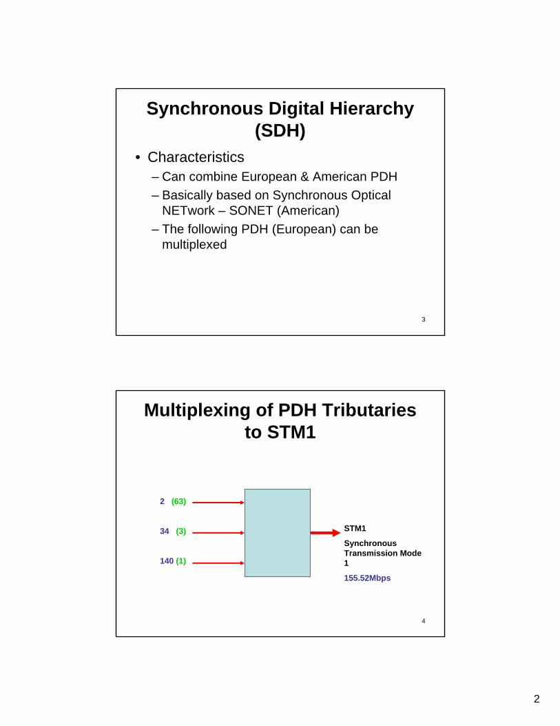
• Characteristics– Can combine European & American PDH– Basically based on Synchronous Optical
NETwork – SONET (American)– The following PDH (European) can be
multiplexed
4
Multiplexing of PDH Tributaries to STM1
2 (63)
34 (3)
140 (1)
STM1
Synchronous Transmission Mode 1
155.52Mbps
3
5
Various Combinations of PDH Tributaries to STM1
• 2.048 Mbps (63 channels) or 34 Mbps (3 channels) or 140 Mbps (1 channel) will form an STM1.
• n1 of 2.048 Mbps, n2 of 34 Mbps can be multiplexed where n1 & n2 will give rise to a total of less than 155.52 Mbps;– if n2 =2, n1(max) = 21– n2 =1, n1(max) = 42
6
Plesiochronous Digital Hierarchy (PDH) - Principles
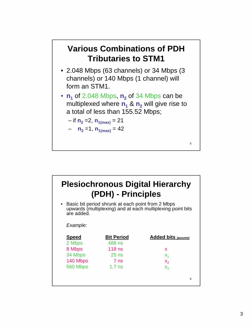
• Basic bit period shrunk at each point from 2 Mbps upwards (multiplexing) and at each multiplexing point bits are added.
Example:
Speed Bit Period Added bits (assume)
2 Mbps 488 ns8 Mbps 118 ns x34 Mbps 25 ns x1140 Mbps 7 ns x2560 Mbps 1.7 ns x3
4
7
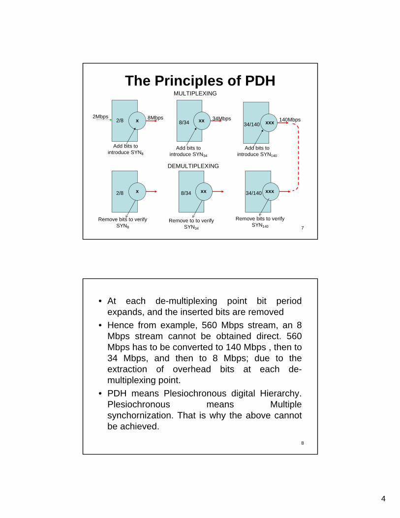
The Principles of PDH
2Mbps
2/8
2/8
Add bits to introduce SYN8
140Mbps34Mbps8Mbps
Add bits to introduce SYN34
Add bits to introduce SYN140
Remove bits to verify SYN8
Remove to to verify SYN34
Remove bits to verify SYN140
DEMULTIPLEXING
MULTIPLEXING
34/140
8/34 34/140
8/34
x
x
xx
xx
xxx
xxx
8
• At each de-multiplexing point bit period expands, and the inserted bits are removed
• Hence from example, 560 Mbps stream, an 8 Mbps stream cannot be obtained direct. 560 Mbps has to be converted to 140 Mbps , then to 34 Mbps, and then to 8 Mbps; due to the extraction of overhead bits at each de-multiplexing point.
• PDH means Plesiochronous digital Hierarchy. Plesiochronous means Multiple synchornization. That is why the above cannot be achieved.
5
9
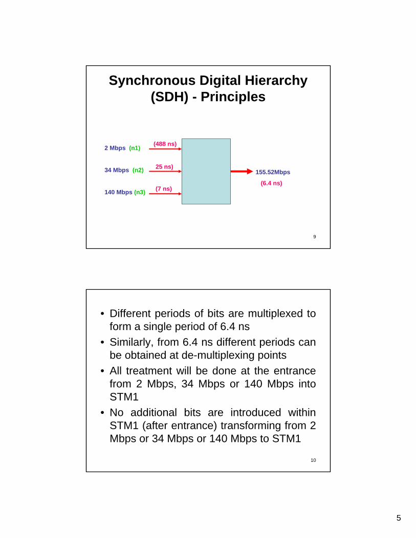
Synchronous Digital Hierarchy (SDH) - Principles
2 Mbps (n1)
34 Mbps (n2)
140 Mbps (n3)
155.52Mbps
(6.4 ns)
(488 ns)
25 ns)
(7 ns)
10
• Different periods of bits are multiplexed to form a single period of 6.4 ns
• Similarly, from 6.4 ns different periods can be obtained at de-multiplexing points
• All treatment will be done at the entrance from 2 Mbps, 34 Mbps or 140 Mbps into STM1
• No additional bits are introduced within STM1 (after entrance) transforming from 2 Mbps or 34 Mbps or 140 Mbps to STM1
6
11
PDH to SDH at the Entry• SDH is always of higher frequency than PDH. The treatment to the
deviation of the PDH streams has to be accommodated in the SDH stream. Complexity increases when the higher order PDH stream tobe placed in the SDH stream. Hence positive, negative & zero justification to be applied, depending upon the PDH stream at the entry to SDH.
• Management of PDH tributary (bit stream) throughout SDH and backagain to de-multiplex to PDH
• This management information is called ‘path Overhead’ (POH). Exchange at which this tributary to be terminated, error control etc.
• At the entry to SDH stream, any PDH tributary will be treated for positive, negative & zero justification, depending upon the primary PCMs characteristics. POH and stuffing bits to convert to a single bit period of 6.4 ns. After this no additional bits are introduced to further shrink the period of 6.4 ns.
• Even in higher order SDH, assume STM4, no additional bits introduced. In STM4 the bit period exactly (6.4 ns)/4 = 1.6 ns
• Same concept extends for higher order STM.
12
SDH structure
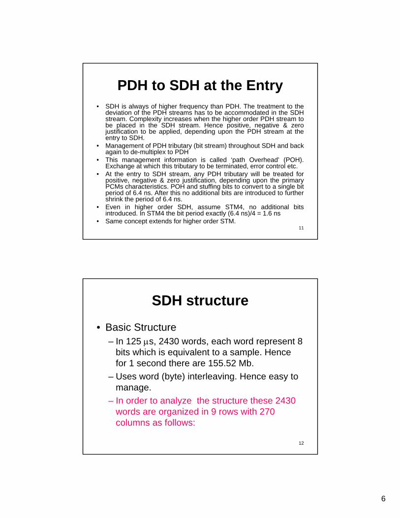
• Basic Structure– In 125 µs, 2430 words, each word represent 8
bits which is equivalent to a sample. Hence for 1 second there are 155.52 Mb.
– Uses word (byte) interleaving. Hence easy to manage.
– In order to analyze the structure these 2430 words are organized in 9 rows with 270 columns as follows:
7
13
Basic Structure
125 µs24302161921608
76543
2712270211
125 µs 2430 x 8 bits
1 µs 155.52 Mbits
14
Structure for 2 Mbps and 34 Mbps
3635343332....................................................54321
756755..........................................................................................................85
8483......21
2.048 Mbps 34.368 Mbps
9
8
7
6
5
4
3
2
1
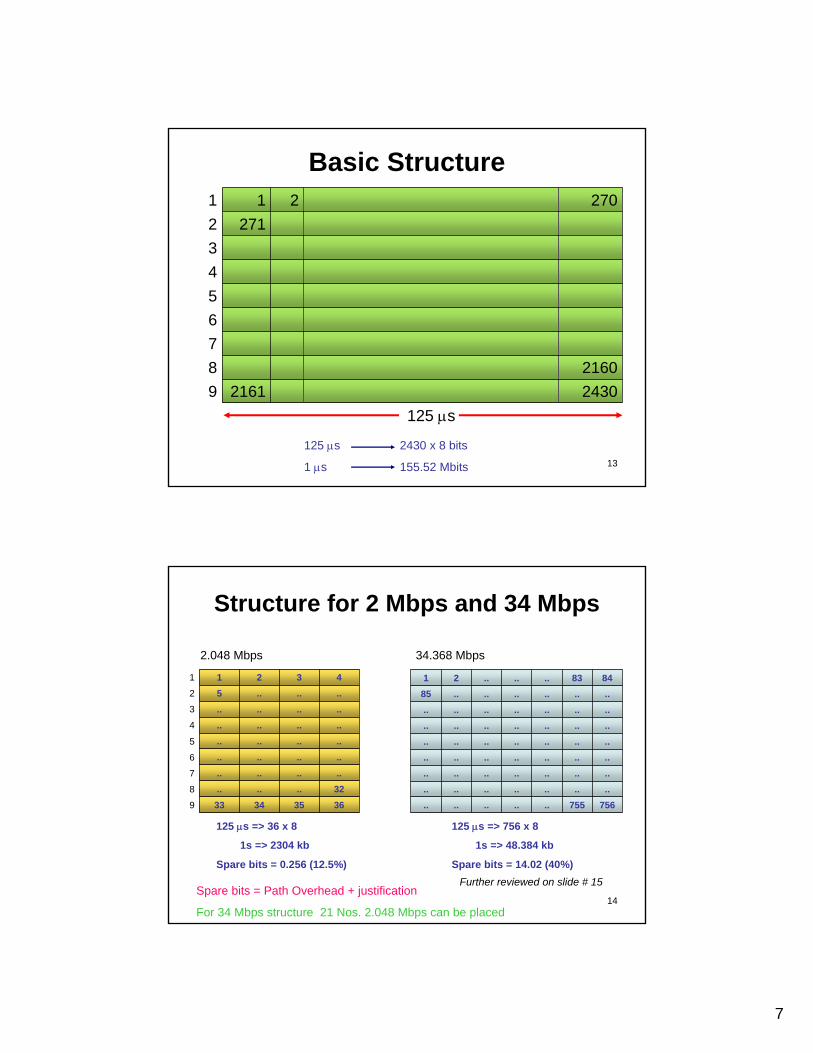
125 µs => 36 x 8
1s => 2304 kb
Spare bits = 0.256 (12.5%)
125 µs => 756 x 8
1s => 48.384 kb
Spare bits = 14.02 (40%)
Spare bits = Path Overhead + justification
For 34 Mbps structure 21 Nos. 2.048 Mbps can be placed
Further reviewed on slide # 15
8
15
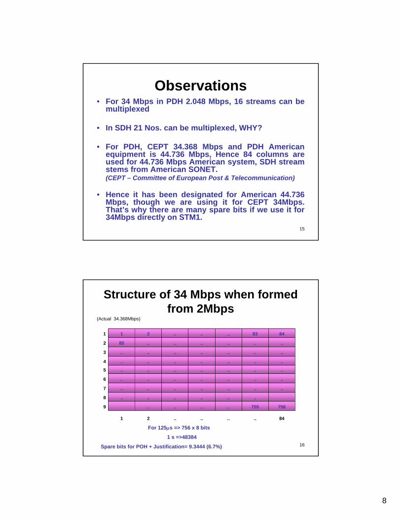
Observations• For 34 Mbps in PDH 2.048 Mbps, 16 streams can be
multiplexed
• In SDH 21 Nos. can be multiplexed, WHY?
• For PDH, CEPT 34.368 Mbps and PDH American equipment is 44.736 Mbps, Hence 84 columns are used for 44.736 Mbps American system, SDH stream stems from American SONET.(CEPT – Committee of European Post & Telecommunication)
• Hence it has been designated for American 44.736 Mbps, though we are using it for CEPT 34Mbps. That’s why there are many spare bits if we use it for 34Mbps directly on STM1.
16
Structure of 34 Mbps when formed from 2Mbps
(Actual 34.368Mbps)
84........21
756755........9
............8
..............7
..............6
..............5
..............4
..............3
............852
8483......211
For 125µs => 756 x 8 bits
1 s =>48384
Spare bits for POH + Justification= 9.3444 (6.7%)
9
17
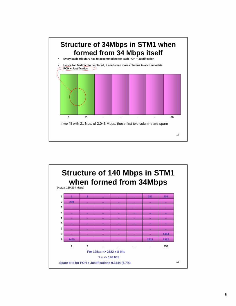
Structure of 34Mbps in STM1 when formed from 34 Mbps itself
• Every basic tributary has to accommodate for each POH + Justification
• Hence for 34 direct to be placed, it needs two more columns to accommodate POH + Justification
86........21
If we fill with 21 Nos. of 2.048 Mbps, these first two columns are spare
18
Structure of 140 Mbps in STM1 when formed from 34Mbps
(Actual 139.264 Mbps)
258........21
23222321........14659
1464............8
..............7
..............6
..............5
..............4
..............3
............2592
258257......211
For 125µs => 2322 x 8 bits
1 s => 148.605
Spare bits for POH + Justification= 9.3444 (6.7%)
10
19
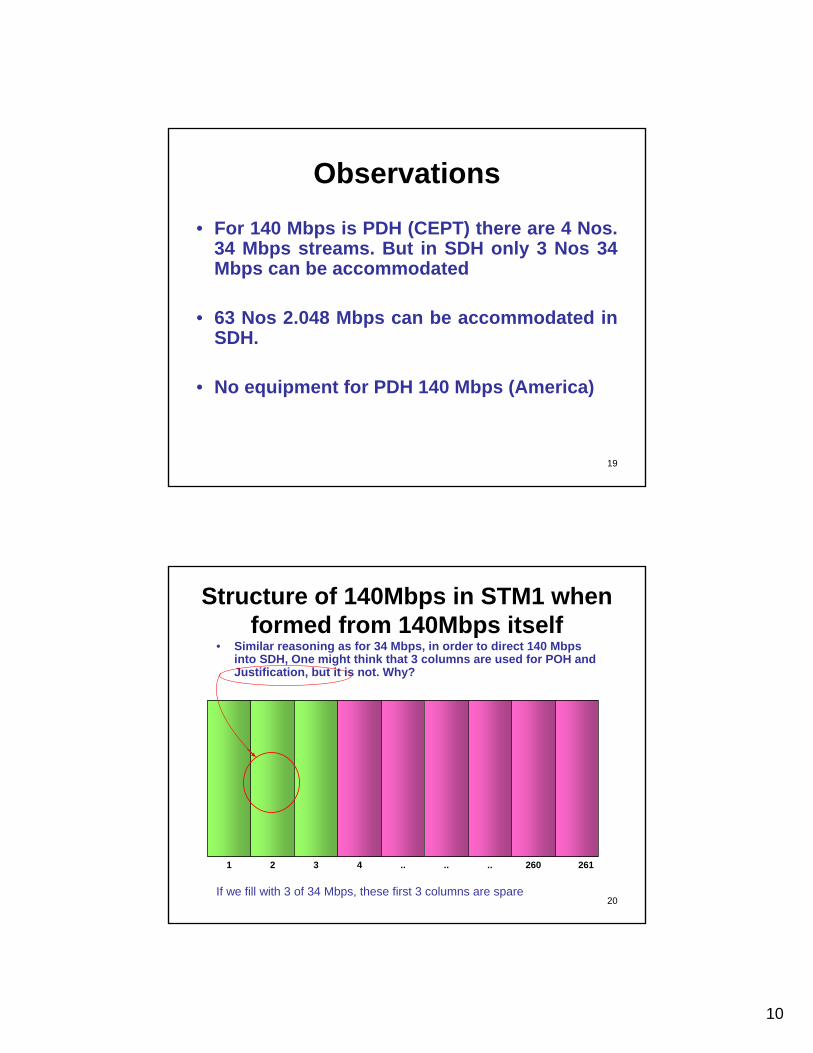
Observations
• For 140 Mbps is PDH (CEPT) there are 4 Nos. 34 Mbps streams. But in SDH only 3 Nos 34 Mbps can be accommodated
• 63 Nos 2.048 Mbps can be accommodated in SDH.
• No equipment for PDH 140 Mbps (America)
20
• Similar reasoning as for 34 Mbps, in order to direct 140 Mbps into SDH, One might think that 3 columns are used for POH and Justification, but it is not. Why?
261260......4321
If we fill with 3 of 34 Mbps, these first 3 columns are spare
Structure of 140Mbps in STM1 when formed from 140Mbps itself
11
21
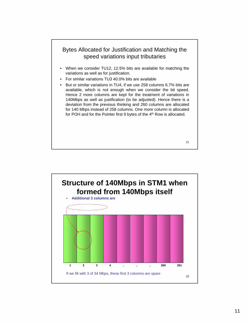
Bytes Allocated for Justification and Matching the speed variations input tributaries
• When we consider TU12, 12.5% bits are available for matching thevariations as well as for justification.
• For similar variations TU3 40.0% bits are available• But or similar variations in TU4, if we use 258 columns 6.7% bits are
available, which is not enough when we consider the bit speed. Hence 2 more columns are kept for the treatment of variations in140Mbps as well as justification (to be adjusted). Hence there is a deviation from the previous thinking and 260 columns are allocated for 140 Mbps instead of 258 columns. One more column is allocated for POH and for the Pointer first 9 bytes of the 4th Row is allocated.
22
• Additional 3 columns are
261260......4321
If we fill with 3 of 34 Mbps, these first 3 columns are spare
Structure of 140Mbps in STM1 when formed from 140Mbps itself
12
23
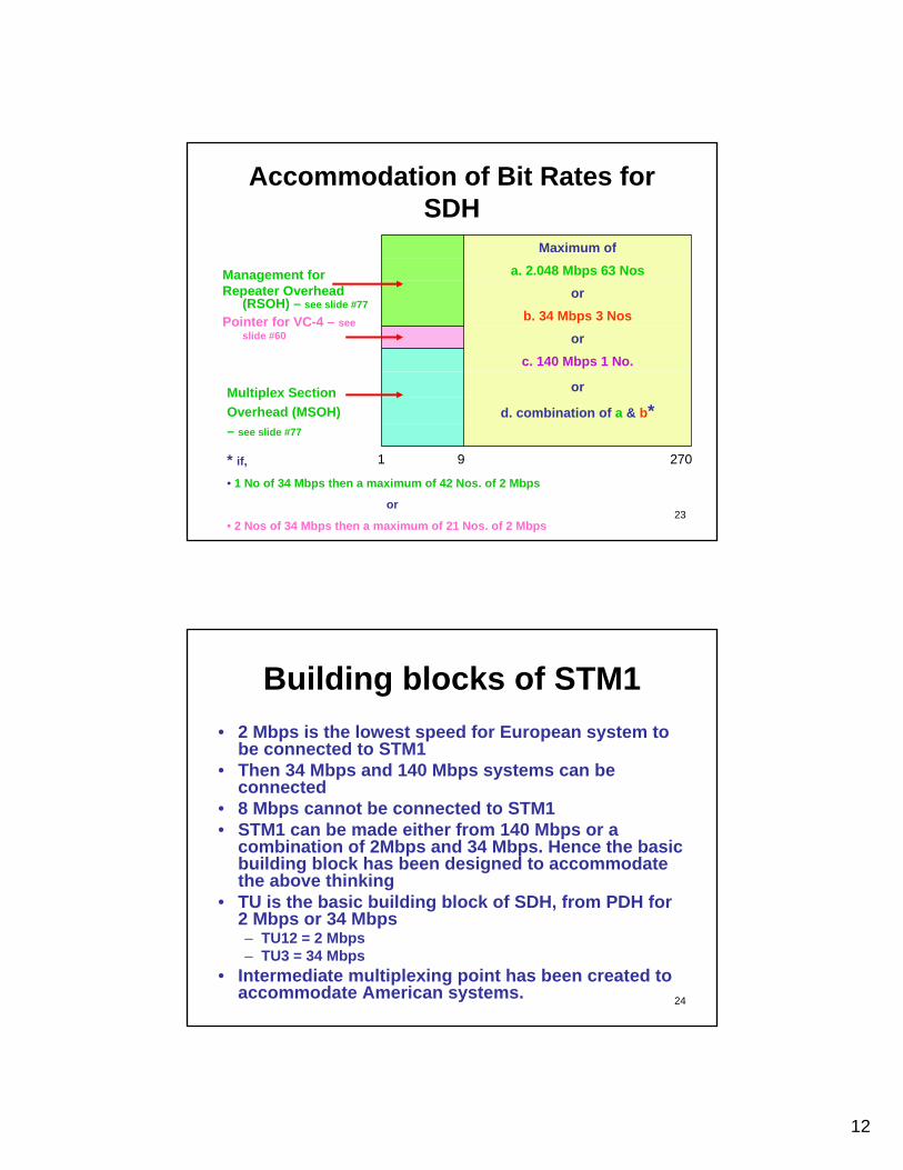
Accommodation of Bit Rates for SDH
Management for Repeater Overhead
(RSOH) – see slide #77
d. combination of a & b*or
c. 140 Mbps 1 No.or
b. 34 Mbps 3 Nosor
a. 2.048 Mbps 63 NosMaximum of
Pointer for VC-4 – see slide #60
* if,• 1 No of 34 Mbps then a maximum of 42 Nos. of 2 Mbps
or
• 2 Nos of 34 Mbps then a maximum of 21 Nos. of 2 Mbps
1 2709
Multiplex Section Overhead (MSOH) – see slide #77
24
Building blocks of STM1• 2 Mbps is the lowest speed for European system to
be connected to STM1• Then 34 Mbps and 140 Mbps systems can be
connected• 8 Mbps cannot be connected to STM1• STM1 can be made either from 140 Mbps or a
combination of 2Mbps and 34 Mbps. Hence the basic building block has been designed to accommodate the above thinking
• TU is the basic building block of SDH, from PDH for 2 Mbps or 34 Mbps– TU12 = 2 Mbps– TU3 = 34 Mbps
• Intermediate multiplexing point has been created to accommodate American systems.
13
25
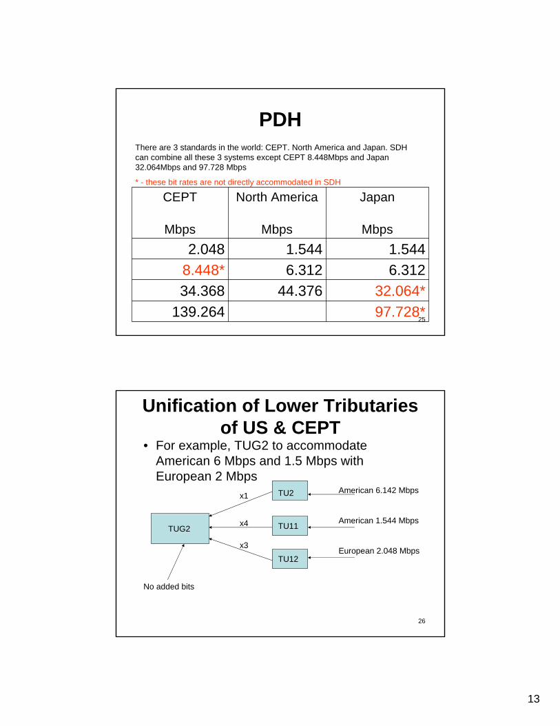
PDH
97.728*139.26432.064*44.37634.368
6.3126.3128.448*1.5441.5442.048
MbpsMbpsMbps
JapanNorth AmericaCEPT
There are 3 standards in the world: CEPT. North America and Japan. SDH can combine all these 3 systems except CEPT 8.448Mbps and Japan 32.064Mbps and 97.728 Mbps
* - these bit rates are not directly accommodated in SDH
26
Unification of Lower Tributaries of US & CEPT
• For example, TUG2 to accommodate American 6 Mbps and 1.5 Mbps with European 2 Mbps
TUG2
TU12
TU11
TU2x1
x4
x3
American 6.142 Mbps
American 1.544 Mbps
European 2.048 Mbps
No added bits
14
27
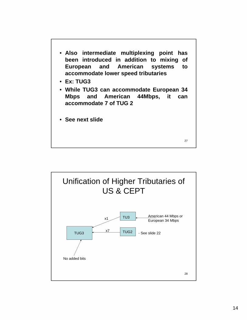
• Also intermediate multiplexing point has been introduced in addition to mixing of European and American systems to accommodate lower speed tributaries
• Ex: TUG3• While TUG3 can accommodate European 34
Mbps and American 44Mbps, it can accommodate 7 of TUG 2
• See next slide
28
TUG3 TUG2
TU3x1
x7
American 44 Mbps or European 34 Mbps
No added bits
- See slide 22
Unification of Higher Tributaries of US & CEPT
15
29
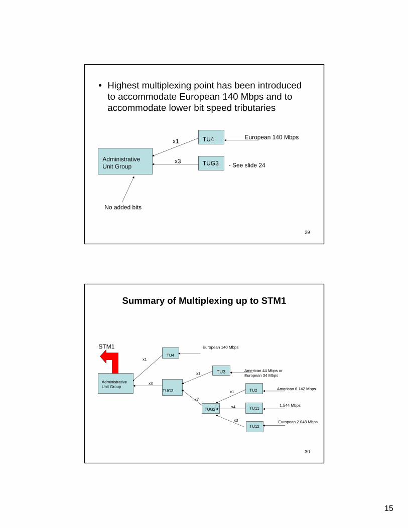
Administrative Unit Group TUG3
TU4x1
x3
European 140 Mbps
No added bits
- See slide 24
• Highest multiplexing point has been introduced to accommodate European 140 Mbps and to accommodate lower bit speed tributaries
30
Administrative Unit Group
TU4x1
x3
European 140 Mbps
TU3
TUG3
TUG2
x1
x7
American 44 Mbps or European 34 Mbps
TU12
TU11
TU2x1
x4
x3
American 6.142 Mbps
1.544 Mbps
European 2.048 Mbps
STM1
Summary of Multiplexing up to STM1
TU3
16
31
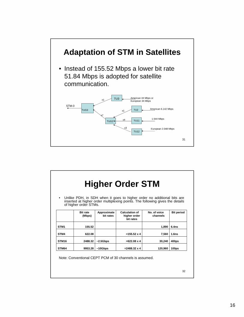
Adaptation of STM in Satellites
• Instead of 155.52 Mbps a lower bit rate 51.84 Mbps is adopted for satellite communication.
TUG3
TUG2
x1
x7
American 44 Mbps or European 34 Mbps
TU12
TU11
TU2x1
x4
x3
American 6.142 Mbps
1.544 Mbps
European 2.048 Mbps
TU3
STM-0
32
Higher Order STM• Unlike PDH, in SDH when it goes to higher order no additional bits are
inserted at higher order multiplexing points. The following gives the details of higher order STMs.
100ps120,960=2488.32 x 4~10Gbps9953.28STM64
400ps30,240=622.08 x 4~2.5Gbps2488.32STM16
1.6ns7,560=155.52 x 4622.08STM4
6.4ns1,890155.52STM1
Bit periodNo. of voice channels
Calculation of higher order
bit rates
Approximate bit rates
Bit rate (Mbps)
Note: Conventional CEPT PCM of 30 channels is assumed.
17
33
Interface Between PDH and SDH• For explanation CEPT system is used. Same concept
applies for other systems. • PDH tributary will be converted to a virtual container by
adding Path Overhead (POH) bits, so that each tributary the originating and destination nodes can be identified.
• This Virtual Container (VC) will be added a Pointer. Hence, made as a Tributary Unit (TU). The pointer thus added will provide the justification of PDH tributary with respect to the SDH tributary.
• The pointer will help at the demultiplexing point to demultiplex to the correct phase of the original PDH signal.
34
What is Justification• Imagine 2 compartments of a train. It is connected with a
pair of buffers and flexible chain. • If the first moving compartment going faster the next.
The chain will pull the next compartment. This is equivalent to ‘Positive Justification.’
• If the first compartment is moving slower than the next the buffers will collide and slow down the next one. This is equivalent to ‘Negative Justification’.
• In this example, the first moving compartment is analogous to higher order tributary and the next is equivalent to primary tributary.
18
35
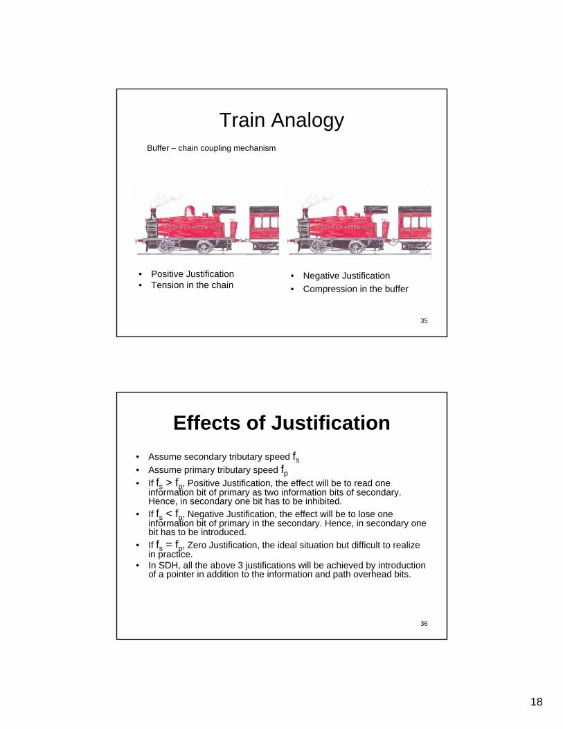
Train Analogy
• Positive Justification• Tension in the chain
• Negative Justification• Compression in the buffer
Buffer – chain coupling mechanism
36
Effects of Justification• Assume secondary tributary speed fs• Assume primary tributary speed fp• If fs > fp, Positive Justification, the effect will be to read one
information bit of primary as two information bits of secondary.Hence, in secondary one bit has to be inhibited.
• If fs < fp, Negative Justification, the effect will be to lose one information bit of primary in the secondary. Hence, in secondary one bit has to be introduced.
• If fs = fp, Zero Justification, the ideal situation but difficult to realize in practice.
• In SDH, all the above 3 justifications will be achieved by introduction of a pointer in addition to the information and path overhead bits.
19
37
Formation of Tributary Units• In SDH, the basic PDH tributary (whether 2Mbps, 34Mbps or 140Mbps) will
be carried in any order of STM as a respective tributary unit of TU-12, TU-3 or AU-4.
• The basic PDH will be treated at the entrance as a container of bits. This container will be added certain overhead bits to match to the STM bit period of 6.7ns. This is called a container (C-12, C-3 or C-4).
• These containers are then added with management-bits-like path overhead. POH plays vital role in operation, administration and maintenance of original PDH tributaries up to the transportation to the required destination of the same. The basic functions of POH includes error detection and transmission path verification. So that this container can be treated as a Virtual Container (VC). Hence this will become VC-12, VC-3 or VC-4.
• This virtual container will be further added with Justification Bits or called as a Pointer to indicated the phase differences between the PDH tributaries with respect to the STM1.
• The STM1 will have a separate pointer to be used when it is multiplexed further to a higher order SDH.
38
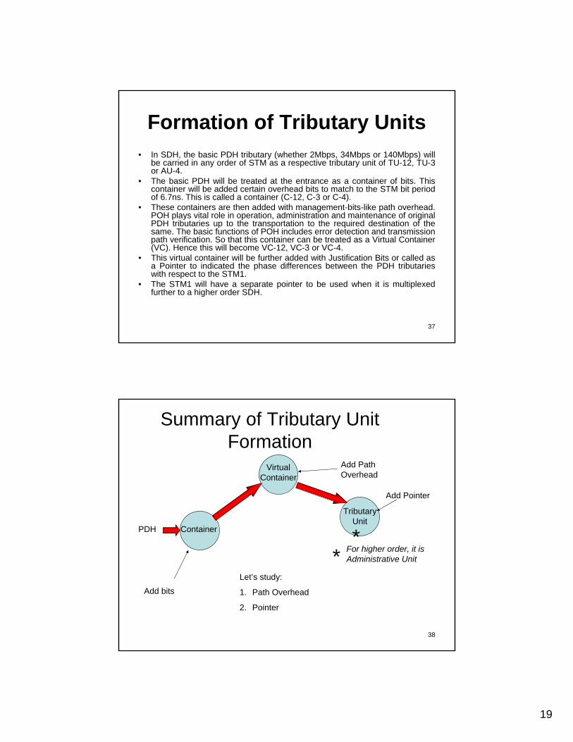
Summary of Tributary Unit Formation
PDH
Add bits
Add Path Overhead
Container
Virtual Container
Add Pointer
Tributary Unit
Let’s study:
1. Path Overhead
2. Pointer
** For higher order, it is
Administrative Unit
20
39
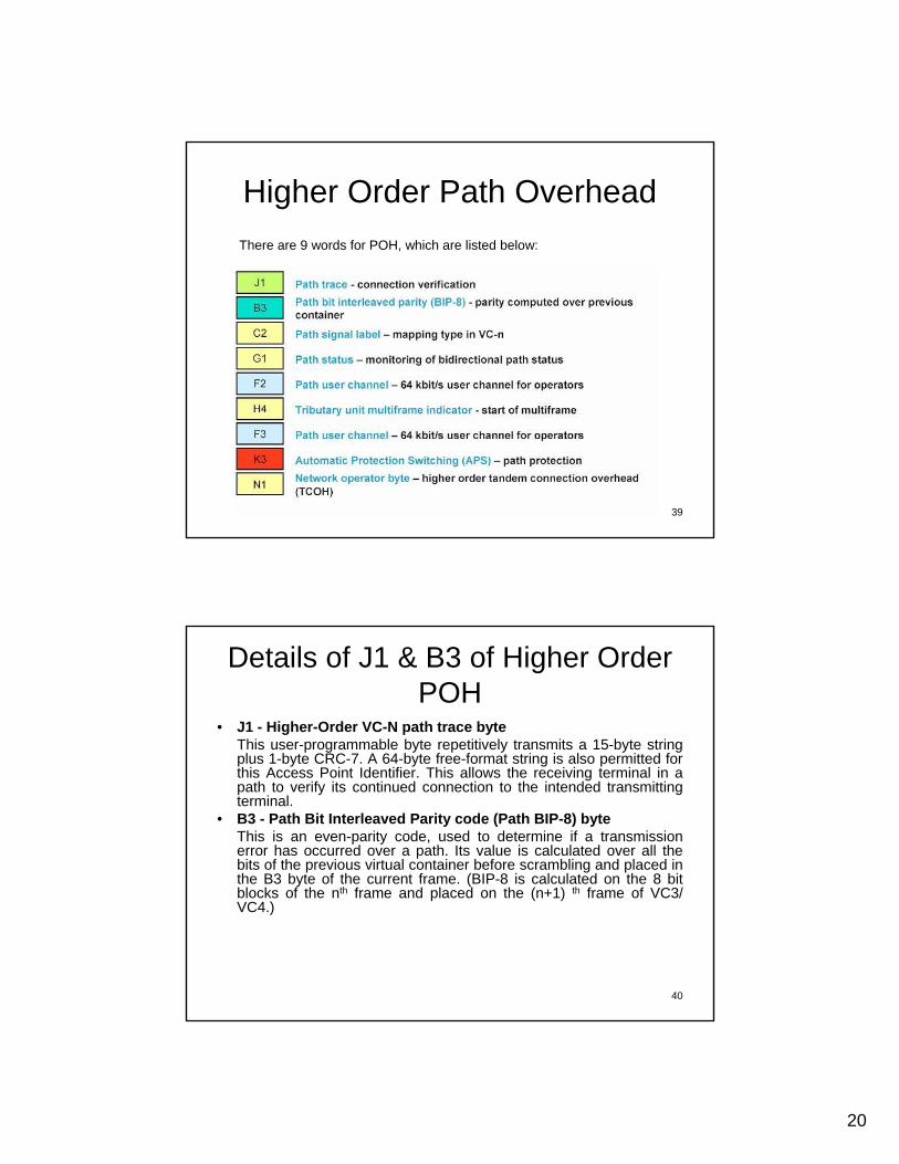
Higher Order Path OverheadThere are 9 words for POH, which are listed below:
40
Details of J1 & B3 of Higher Order POH
• J1 - Higher-Order VC-N path trace byteThis user-programmable byte repetitively transmits a 15-byte string plus 1-byte CRC-7. A 64-byte free-format string is also permitted for this Access Point Identifier. This allows the receiving terminal in a path to verify its continued connection to the intended transmitting terminal.
• B3 - Path Bit Interleaved Parity code (Path BIP-8) byteThis is an even-parity code, used to determine if a transmission error has occurred over a path. Its value is calculated over all the bits of the previous virtual container before scrambling and placed in the B3 byte of the current frame. (BIP-8 is calculated on the 8 bit blocks of the nth frame and placed on the (n+1) th frame of VC3/ VC4.)
21
41
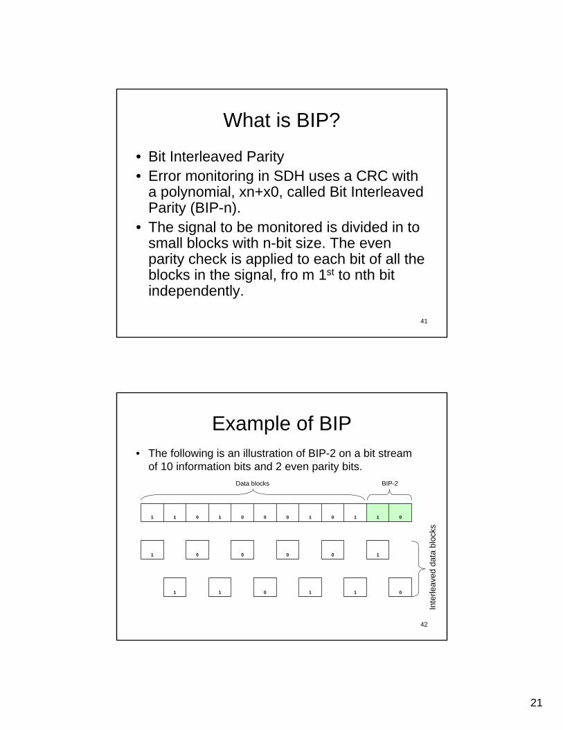
What is BIP?
• Bit Interleaved Parity• Error monitoring in SDH uses a CRC with
a polynomial, xn+x0, called Bit Interleaved Parity (BIP-n).
• The signal to be monitored is divided in to small blocks with n-bit size. The even parity check is applied to each bit of all the blocks in the signal, fro m 1st to nth bit independently.
42
Example of BIP• The following is an illustration of BIP-2 on a bit stream
of 10 information bits and 2 even parity bits.
011011
100001
011010001011
Data blocks BIP-2
Inte
rleav
ed d
ata
bloc
ks
22
43
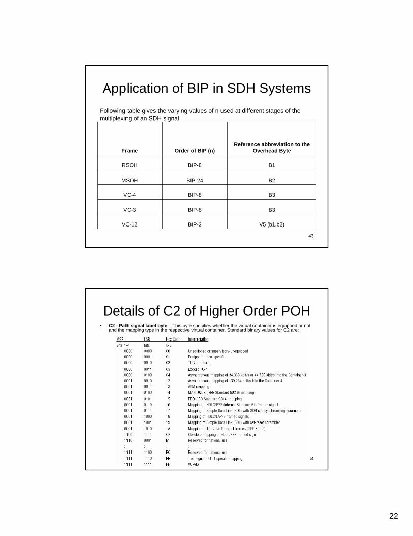
Application of BIP in SDH Systems
V5 (b1,b2)BIP-2VC-12
B3BIP-8VC-3
B3BIP-8VC-4
B2BIP-24MSOH
B1BIP-8RSOH
Reference abbreviation to the Overhead ByteOrder of BIP (n)Frame
Following table gives the varying values of n used at different stages of the multiplexing of an SDH signal
44
Details of C2 of Higher Order POH• C2 - Path signal label byte – This byte specifies whether the virtual container is equipped or not
and the mapping type in the respective virtual container. Standard binary values for C2 are:
23
45
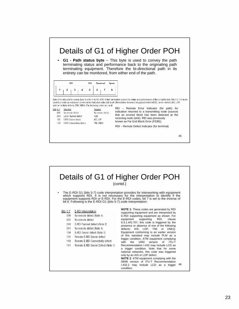
Details of G1 of Higher Order POH• G1 - Path status byte – This byte is used to convey the path
terminating status and performance back to the originating path terminating equipment. Therefore the bi-directional path in its entirety can be monitored, from either end of the path.
REI – Remote Error Indicator (for path) An indication returned to a transmitting node (source) that an errored block has been detected at the receiving node (sink). REI was previouslyknown as Far End Block Error (FEBE).
RDI – Remote Defect Indicator (for terminal)
46
Details of G1 of Higher Order POH (contd.)
• The E-RDI G1 (bits 5-7) code interpretation provides for interworking with equipment which supports RDI. It is not necessary for the interpretation to identify if the equipment supports RDI or E-RDI. For the E-RDI codes, bit 7 is set to the inverse of bit 6. Following is the E-RDI G1 (bits 5-7) code interpretation:
NOTE 1: These codes are generated by RDI supporting equipment and are interpreted by E-RDI supporting equipment as shown. For equipment supporting RDI, clause 9.3.1.4/G.707, this code is triggered by the presence or absence of one of the following defects: AIS, LOP, TIM, or UNEQ. Equipment conforming to an earlier version of this standard may include PLM as a trigger condition. ATM equipment complying with the 1993 version of ITU-T Recommendation I.432 may include LCD as a trigger condition. Note that for some national networks, this code was triggered only by an AIS or LOP defect.NOTE 2: ATM equipment complying with the 08/96 version of ITU-T Recommendation I.432.2 may include LCD as a trigger condition.
24
47
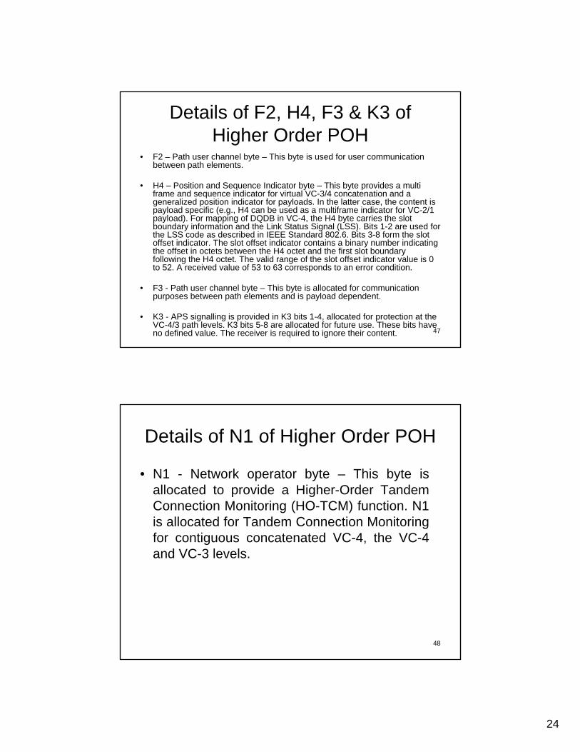
Details of F2, H4, F3 & K3 of Higher Order POH
• F2 – Path user channel byte – This byte is used for user communication between path elements.
• H4 – Position and Sequence Indicator byte – This byte provides a multi frame and sequence indicator for virtual VC-3/4 concatenation and a generalized position indicator for payloads. In the latter case, the content is payload specific (e.g., H4 can be used as a multiframe indicator for VC-2/1 payload). For mapping of DQDB in VC-4, the H4 byte carries the slot boundary information and the Link Status Signal (LSS). Bits 1-2 are used for the LSS code as described in IEEE Standard 802.6. Bits 3-8 form the slot offset indicator. The slot offset indicator contains a binary number indicating the offset in octets between the H4 octet and the first slot boundary following the H4 octet. The valid range of the slot offset indicator value is 0 to 52. A received value of 53 to 63 corresponds to an error condition.
• F3 - Path user channel byte – This byte is allocated for communication purposes between path elements and is payload dependent.
• K3 - APS signalling is provided in K3 bits 1-4, allocated for protection at the VC-4/3 path levels. K3 bits 5-8 are allocated for future use. These bits have no defined value. The receiver is required to ignore their content.
48
Details of N1 of Higher Order POH
• N1 - Network operator byte – This byte is allocated to provide a Higher-Order Tandem Connection Monitoring (HO-TCM) function. N1 is allocated for Tandem Connection Monitoring for contiguous concatenated VC-4, the VC-4 and VC-3 levels.
25
49
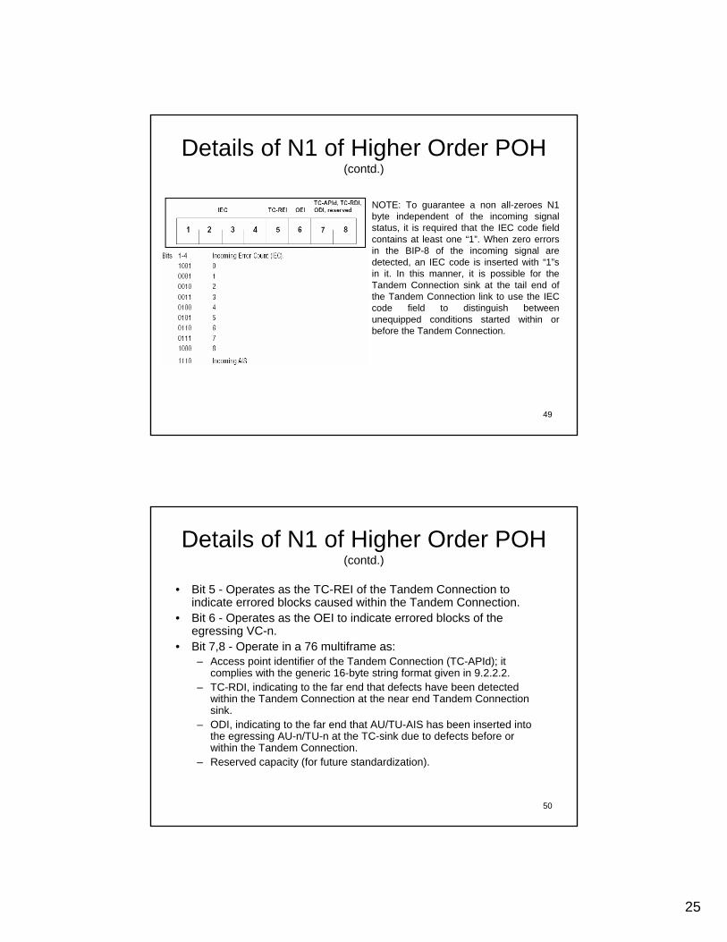
Details of N1 of Higher Order POH (contd.)
NOTE: To guarantee a non all-zeroes N1 byte independent of the incoming signal status, it is required that the IEC code field contains at least one “1”. When zero errors in the BIP-8 of the incoming signal are detected, an IEC code is inserted with “1”s in it. In this manner, it is possible for the Tandem Connection sink at the tail end of the Tandem Connection link to use the IEC code field to distinguish between unequipped conditions started within or before the Tandem Connection.
50
Details of N1 of Higher Order POH (contd.)
• Bit 5 - Operates as the TC-REI of the Tandem Connection to indicate errored blocks caused within the Tandem Connection.
• Bit 6 - Operates as the OEI to indicate errored blocks of the egressing VC-n.
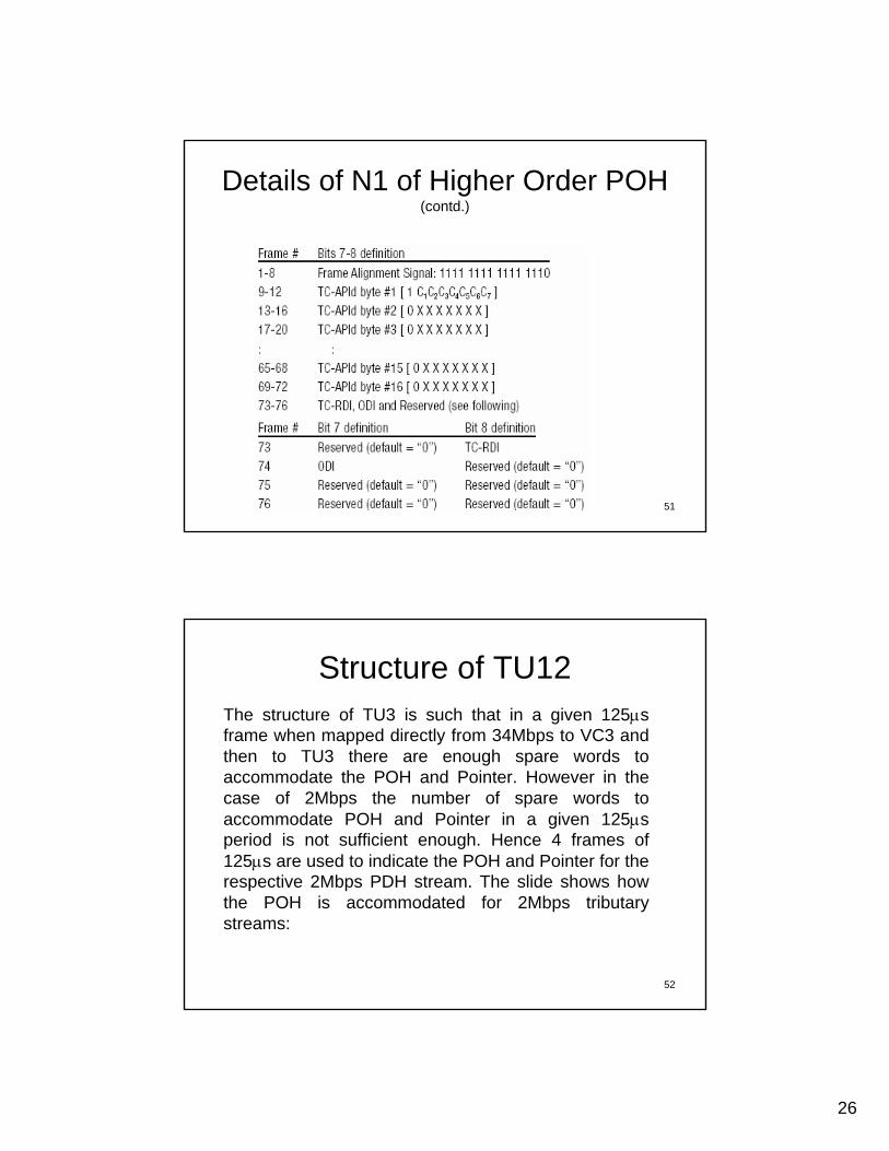
• Bit 7,8 - Operate in a 76 multiframe as:– Access point identifier of the Tandem Connection (TC-APId); it
complies with the generic 16-byte string format given in 9.2.2.2.– TC-RDI, indicating to the far end that defects have been detected
within the Tandem Connection at the near end Tandem Connection sink.
– ODI, indicating to the far end that AU/TU-AIS has been inserted into the egressing AU-n/TU-n at the TC-sink due to defects before or within the Tandem Connection.
– Reserved capacity (for future standardization).
26
51
Details of N1 of Higher Order POH (contd.)
52
Structure of TU12The structure of TU3 is such that in a given 125µs frame when mapped directly from 34Mbps to VC3 and then to TU3 there are enough spare words to accommodate the POH and Pointer. However in the case of 2Mbps the number of spare words to accommodate POH and Pointer in a given 125µs period is not sufficient enough. Hence 4 frames of 125µs are used to indicate the POH and Pointer for the respective 2Mbps PDH stream. The slide shows how the POH is accommodated for 2Mbps tributary streams:
27
53
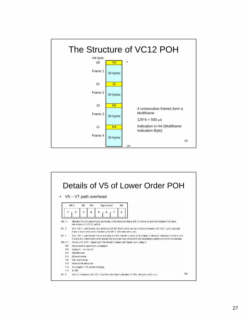
The Structure of VC12 POH0
140
4 consecutive frames form a Multiframe
125*4 = 500 µs
Indication in H4 (MultiframeIndication Byte)
H4 byte00 V5
Frame 1
01 J2
Frame 2
10 N2
Frame 3
11 K4
Frame 4
34 bytes
34 bytes
34 bytes
34 bytes
54
Details of V5 of Lower Order POH• V5 – VT path overhead
28
55
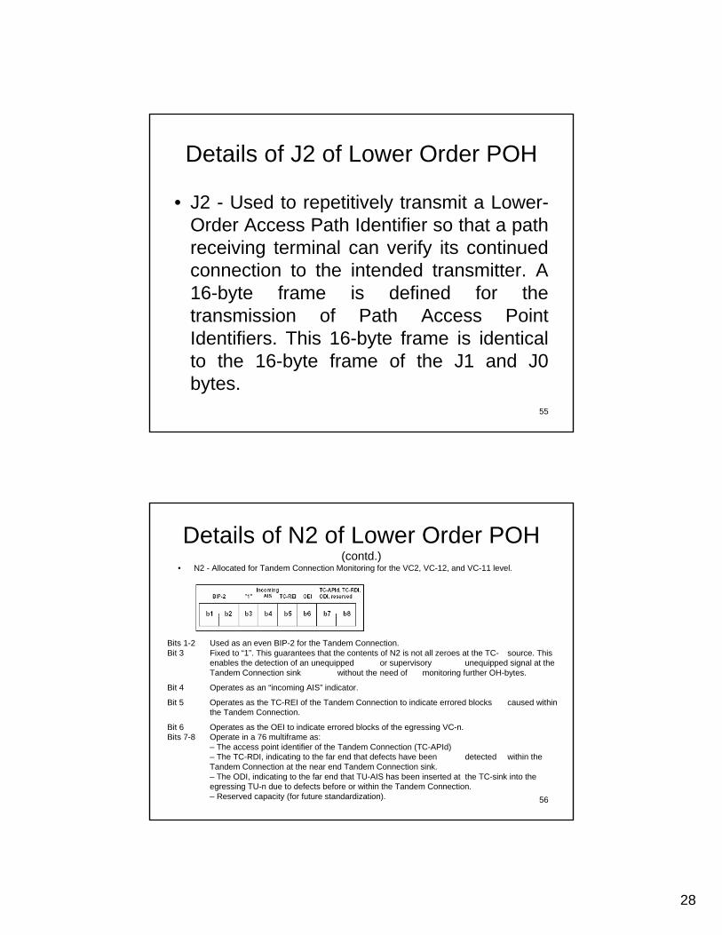
Details of J2 of Lower Order POH
• J2 - Used to repetitively transmit a Lower-Order Access Path Identifier so that a path receiving terminal can verify its continued connection to the intended transmitter. A 16-byte frame is defined for the transmission of Path Access Point Identifiers. This 16-byte frame is identical to the 16-byte frame of the J1 and J0bytes.
56
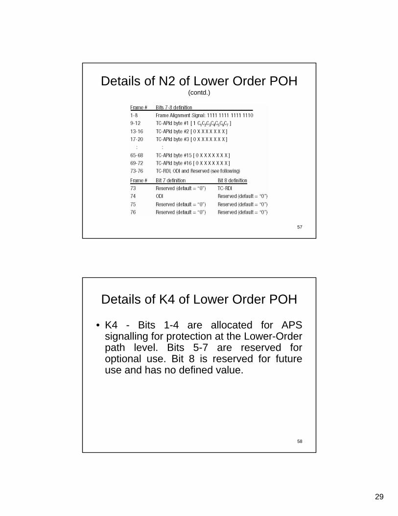
Details of N2 of Lower Order POH (contd.)
• N2 - Allocated for Tandem Connection Monitoring for the VC2, VC-12, and VC-11 level.
Bits 1-2 Used as an even BIP-2 for the Tandem Connection.Bit 3 Fixed to “1”. This guarantees that the contents of N2 is not all zeroes at the TC- source. This
enables the detection of an unequipped or supervisory unequipped signal at theTandem Connection sink without the need of monitoring further OH-bytes.
Bit 4 Operates as an “incoming AIS” indicator.
Bit 5 Operates as the TC-REI of the Tandem Connection to indicate errored blocks caused within the Tandem Connection.
Bit 6 Operates as the OEI to indicate errored blocks of the egressing VC-n.Bits 7-8 Operate in a 76 multiframe as:
– The access point identifier of the Tandem Connection (TC-APId)– The TC-RDI, indicating to the far end that defects have been detected within the Tandem Connection at the near end Tandem Connection sink.– The ODI, indicating to the far end that TU-AIS has been inserted at the TC-sink into the egressing TU-n due to defects before or within the Tandem Connection.– Reserved capacity (for future standardization).
29
57
Details of N2 of Lower Order POH (contd.)
58
Details of K4 of Lower Order POH
• K4 - Bits 1-4 are allocated for APS signalling for protection at the Lower-Order path level. Bits 5-7 are reserved for optional use. Bit 8 is reserved for future use and has no defined value.

30
59
Comparison of POH in Higher and Lower Orders
N2N1Network Operator ByteSpare (unused)
K4K3Automatic Protection Switch signalingN/AH4Multiframe Position IndicatorN/AF2,F364kb clear channels
V5(b3,4,8)G1Remote Alarm IndicationV5(b5-b7)C2Indication of VC compositionV5(b1-b2)B3Bit Interleaved parity Check Byte
J2J1verification of VC connection
VC12 POH Byte
VC3,4 POH ByteFunction
60
Pointers• Application of Pointer
– A Pointer is used to address a particular location within an AU or a TU structure. There are mainly 2 types of pointers
1. AU Pointers: used to point at Higher Order VC’s (VC-4,3) in an STM frame
2. TU Pointers: used to point at Lower Order VC’s (VC-12) in higher order VC
Each of these pointers carry the offset number (address) at which the 1st byte of the payload is located, within the frame. The offset numbering of AU4, TU3, TU12, frames are shown in slide # 66, 68, 71. The offset numbering of TUs/AUs will be according to the CCITT Rec. G.707.
31
61
Functions of a Pointer
• 1. Minimization of multiplexing Delay– This is the main advantage of pointers. Normally signals from different
originating points differ in their phases, because of different transmission length and different clock generation. In the usual multiplexing process, to align them, each signal has to be written into memories and read out using a new phase of the frame to be multiplexed. Thus, it is inevitable to cause additional delay of half of the frame time in average and one frame time at maximum. Also, it requires large capacity memories.
– To avoid above inconveniences, this pointer method was introduced into the multiplexing of SDH signal. A pointer is assigned to each VC to be multiplexed and it indicates relative phase shift between the VC and the new frame by using the address number in the new frame. As a matter of course, every VC has different pointer value. The pointer is renewed at every multiplexing process, so it is not necessary to introduce undesirable additional delays.
• 2. Frequency Justification– Generally this function is not required in an SDH network since all network
elements are synchronized to a single clock. But if the VC’s are transported over different networks, and if a network element is in an abnormal condition, justification is necessary to absorb any frequency differences between payload and the frames. There are 2 types of justification in SDH:a. Positive Justification: If the frame speed of the STM is higher than the payload arrival speed.b. Negative justification: If the frame speed of the STM is lower than the payload arrival speed.
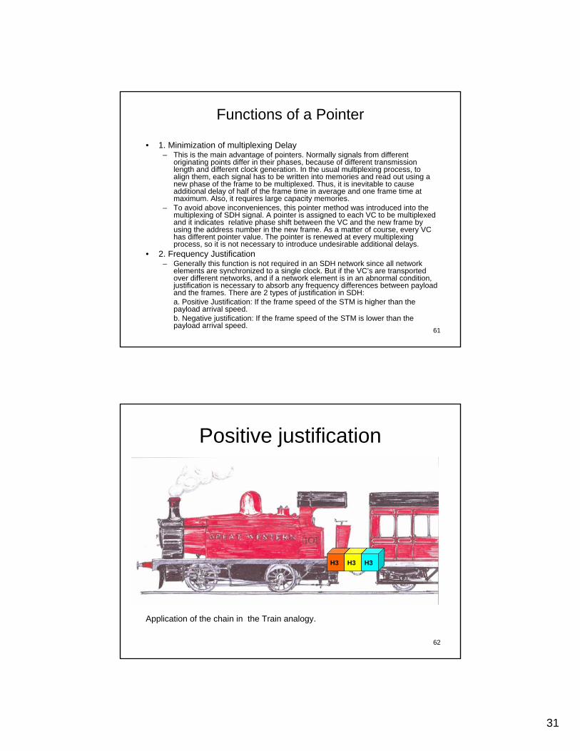
62
Positive justification
H3 H3 H3
Application of the chain in the Train analogy.
32
63
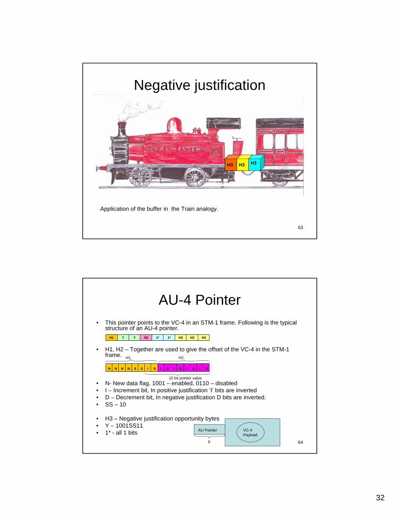
Negative justification
H3H3 H3H3 H3 H3
Application of the buffer in the Train analogy.
64
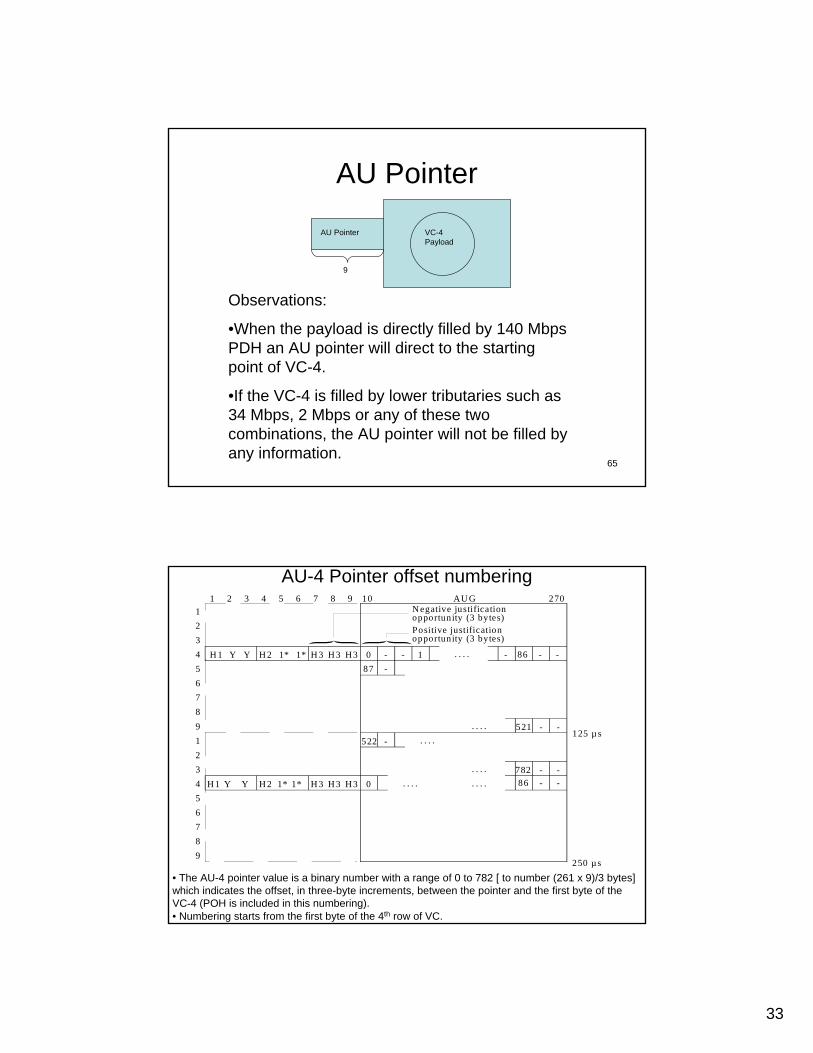
• This pointer points to the VC-4 in an STM-1 frame. Following is the typical structure of an AU-4 pointer.
• H1, H2 – Together are used to give the offset of the VC-4 in the STM-1 frame.
• N- New data flag, 1001 – enabled, 0110 – disabled• I – Increment bit, In positive justification ‘I’ bits are inverted• D – Decrement bit, In negative justification D bits are inverted.• SS – 10
• H3 – Negative justification opportunity bytes• Y – 1001SS11• 1* - all 1 bits
AU-4 Pointer
H3H3H31*1*H2YYH1
DIDIDIDIDISSNNNN
10 bit pointer value
H1 H2
AU Pointer VC-4 Payload
9
33
65
AU Pointer
AU Pointer VC-4 Payload
9
Observations:
•When the payload is directly filled by 140 Mbps PDH an AU pointer will direct to the starting point of VC-4.
•If the VC-4 is filled by lower tributaries such as 34 Mbps, 2 Mbps or any of these two combinations, the AU pointer will not be filled by any information.
66
AU-4 Pointer offset numbering
1234 H 156789
H 3 H 3 H3 0 - - 187
- -- 86
123456789
-
- -521
- -782- -860
522 -
. . . .
. . . .
. . . .
. . . .
. . . .
. . . .
H 2Y
1 2 3 4 5 6 7 8 9 10 270
125 µs
250 µs
H 1 H 3 H 3 H3H 2YY
Y 1* 1*
1* 1*
T1522980-96
AU GN egative justificationopportunity (3 bytes)Positive justificationopportunity (3 bytes)
A ll 1s byte1001 SS 11 (S b its a re unspecified)
1*Y
• The AU-4 pointer value is a binary number with a range of 0 to 782 [ to number (261 x 9)/3 bytes] which indicates the offset, in three-byte increments, between the pointer and the first byte of the VC-4 (POH is included in this numbering).• Numbering starts from the first byte of the 4th row of VC.
34
67
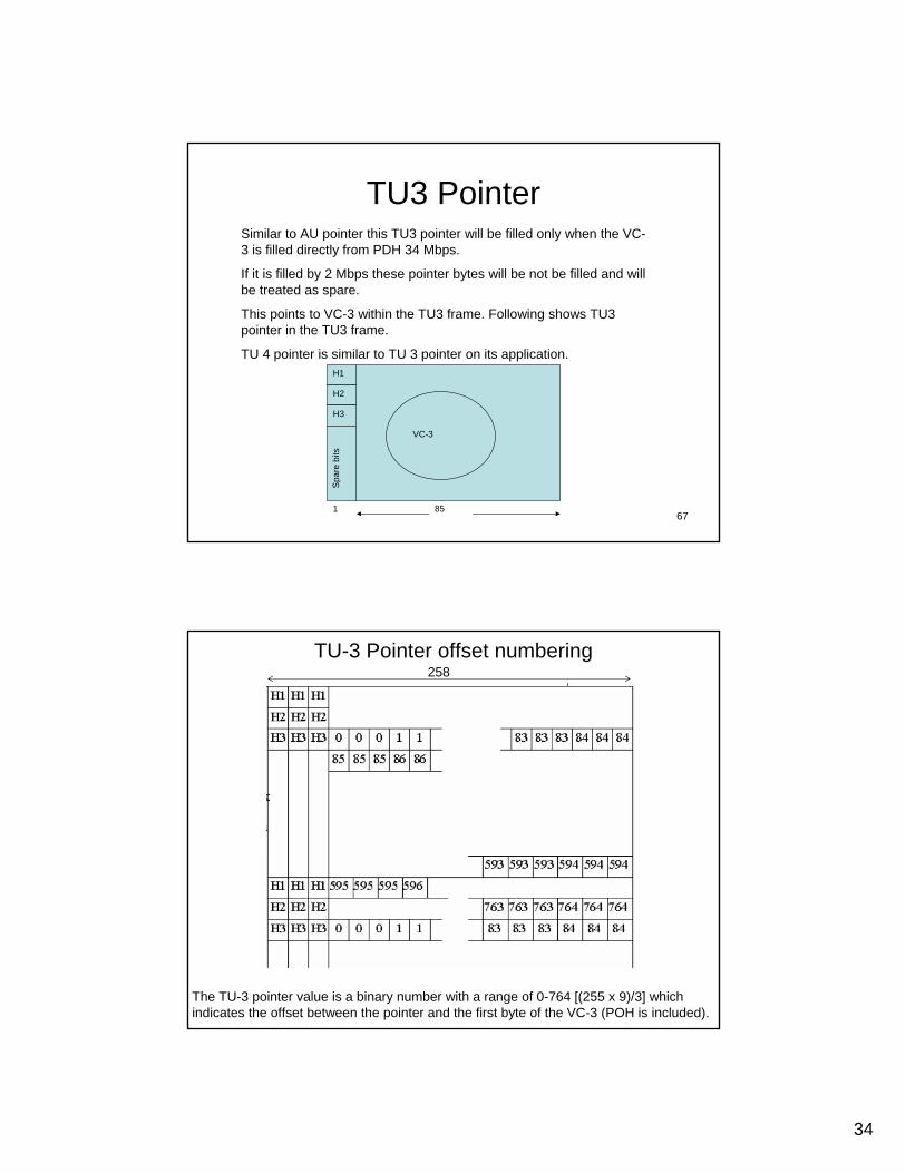
TU3 Pointer
H2
Spa
re b
its
H3
1 85
VC-3
H1
Similar to AU pointer this TU3 pointer will be filled only when the VC-3 is filled directly from PDH 34 Mbps.
If it is filled by 2 Mbps these pointer bytes will be not be filled and will be treated as spare.
This points to VC-3 within the TU3 frame. Following shows TU3 pointer in the TU3 frame.
TU 4 pointer is similar to TU 3 pointer on its application.
68
TU-3 Pointer offset numbering
The TU-3 pointer value is a binary number with a range of 0-764 [(255 x 9)/3] which indicates the offset between the pointer and the first byte of the VC-3 (POH is included).
258

35
69
AU-n/TU-3 Pointer (H1, H2, H3) Coding
T1540710-00
N N N N S S I D I D I D I D I D1 2 3 4 5 6 7 8 9 10 11 12 13 14 15 16
H1 H2 H3
10 AU-4, AU-4-Xc, AU-3, TU-3
IDN
IncrementDecrementNew data flag
Negativejustificationopportunity
Positivejustificationopportunity
Negative justification– Invert 5 D-bits– Accept majority vote
SS bits AU-n/TU-n type
Concatenation indication– 1001SS1111111111 (SS bits are unspecified)
Positive justification– Invert 5 I-bits– Accept majority vote
10 bit pointer value
New data flag – Enabled when at least 3 out of 4 bits match "1001" – Disabled when at least 3 out of 4 bits match "0110" – Invalid with other codes
Pointer value (b7-b16)– Normal range is:
for AU-4, AU-3: 0-782 decimal for TU-3: 0-764 decimal
70
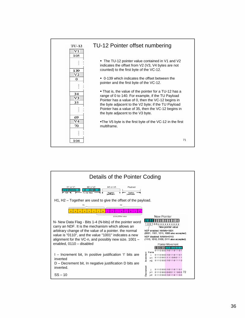
TU12 PointerThis points to VC-12 within the TU12 frame. Following shows TU12 pointer in
the TU12 frame.
V1 ~ V4
4
9VC-12
35 bytes
V4
35 bytes
V3
35 bytes
V2
35 bytes
V1
500 µs
36
71
The TU-12 pointer value contained in V1 and V2 indicates the offset from V2 (V3, V4 bytes are not counted) to the first byte of the VC-12.
0-139 which indicates the offset between the pointer and the first byte of the VC-12.
That is, the value of the pointer for a TU-12 has a range of 0 to 140. For example, if the TU Payload Pointer has a value of 0, then the VC-12 begins in the byte adjacent to the V2 byte; if the TU Payload Pointer has a value of 35, then the VC-12 begins in the byte adjacent to the V3 byte.
The V5 byte is the first byte of the VC-12 in the firstmultiframe.
TU-12 Pointer offset numbering
72
Details of the Pointer Coding
H1, H2 – Together are used to give the offset of the payload.
DIDIDIDIDISSNNNN
10 bit pointer value
H1 H2
N- New Data Flag - Bits 1-4 (N-bits) of the pointer word carry an NDF. It is the mechanism which allows an arbitrary change of the value of a pointer. the normal value is "0110", and the value "1001" indicates a new alignment for the VC-n, and possibly new size. 1001 –enabled, 0110 – disabled
I – Increment bit, In positive justification ‘I’ bits are invertedD – Decrement bit, In negative justification D bits are inverted.
SS – 10
37
73
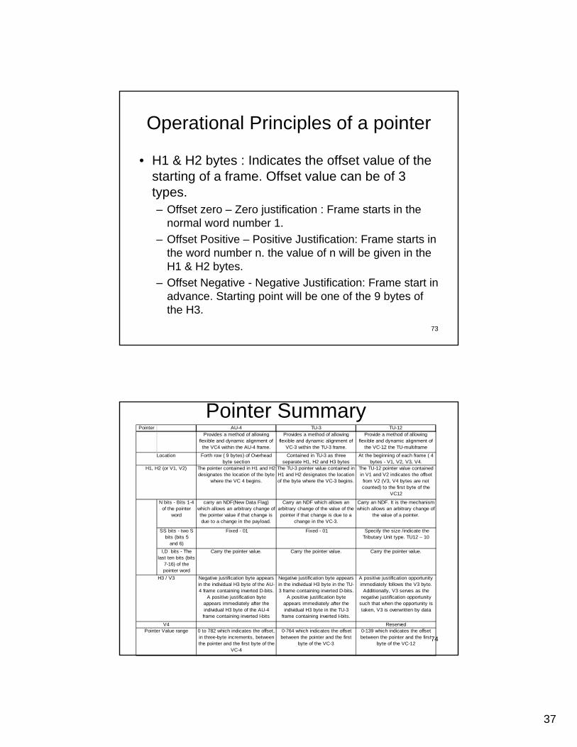
Operational Principles of a pointer
• H1 & H2 bytes : Indicates the offset value of the starting of a frame. Offset value can be of 3 types. – Offset zero – Zero justification : Frame starts in the
normal word number 1.– Offset Positive – Positive Justification: Frame starts in
the word number n. the value of n will be given in the H1 & H2 bytes.
– Offset Negative - Negative Justification: Frame start in advance. Starting point will be one of the 9 bytes of the H3.
74
Pointer AU-4 TU-3 TU-12 Provides a method of allowing
flexible and dynamic alignment of the VC4 within the AU-4 frame.
Provides a method of allowing flexible and dynamic alignment of
VC-3 within the TU-3 frame.
Provide a method of allowing flexible and dynamic alignment of
the VC-12 the TU-multiframe
Forth row ( 9 bytes) of Overhead byte section
Contained in TU-3 as three separate H1, H2 and H3 bytes
At the beginning of each frame ( 4 bytes - V1, V2, V3, V4.
The pointer contained in H1 and H2 designates the location of the byte
where the VC 4 begins.
The TU-3 pointer value contained in H1 and H2 designates the location of the byte where the VC-3 begins.
The TU-12 pointer value contained in V1 and V2 indicates the offset from V2 (V3, V4 bytes are not counted) to the first byte of the
VC12
N bits - Bits 1-4 of the pointer
word
carry an NDF(New Data Flag) which allows an arbitrary change of the pointer value if that change is due to a change in the payload.
Carry an NDF which allows an arbitrary change of the value of the pointer if that change is due to a
change in the VC-3.
Carry an NDF. It is the mechanism which allows an arbitrary change of
the value of a pointer.
SS bits - two S bits (bits 5
and 6)
Fixed - 01 Fixed - 01 Specify the size /indicate the Tributary Unit type. TU12 – 10
I,D bits - The last ten bits (bits
7-16) of the pointer word
Carry the pointer value. Carry the pointer value. Carry the pointer value.
Negative justification byte appears in the individual H3 byte of the AU-4 frame containing inverted D-bits.
A positive justification byte appears immediately after the individual H3 byte of the AU-4 frame containing inverted I-bits
Negative justification byte appears in the individual H3 byte in the TU-3 frame containing inverted D-bits.
A positive justification byte appears immediately after the individual H3 byte in the TU-3
frame containing inverted I-bits.
A positive justification opportunity immediately follows the V3 byte.
Additionally, V3 serves as the negative justification opportunity
such that when the opportunity is taken, V3 is overwritten by data
Reserved0 to 782 which indicates the offset, in three-byte increments, between the pointer and the first byte of the
VC-4
0-764 which indicates the offset between the pointer and the first
byte of the VC-3
0-139 which indicates the offset between the pointer and the first
byte of the VC-12
V4Pointer Value range
Location
H1, H2 (or V1, V2)
H3 / V3
Pointer Summary
38
75
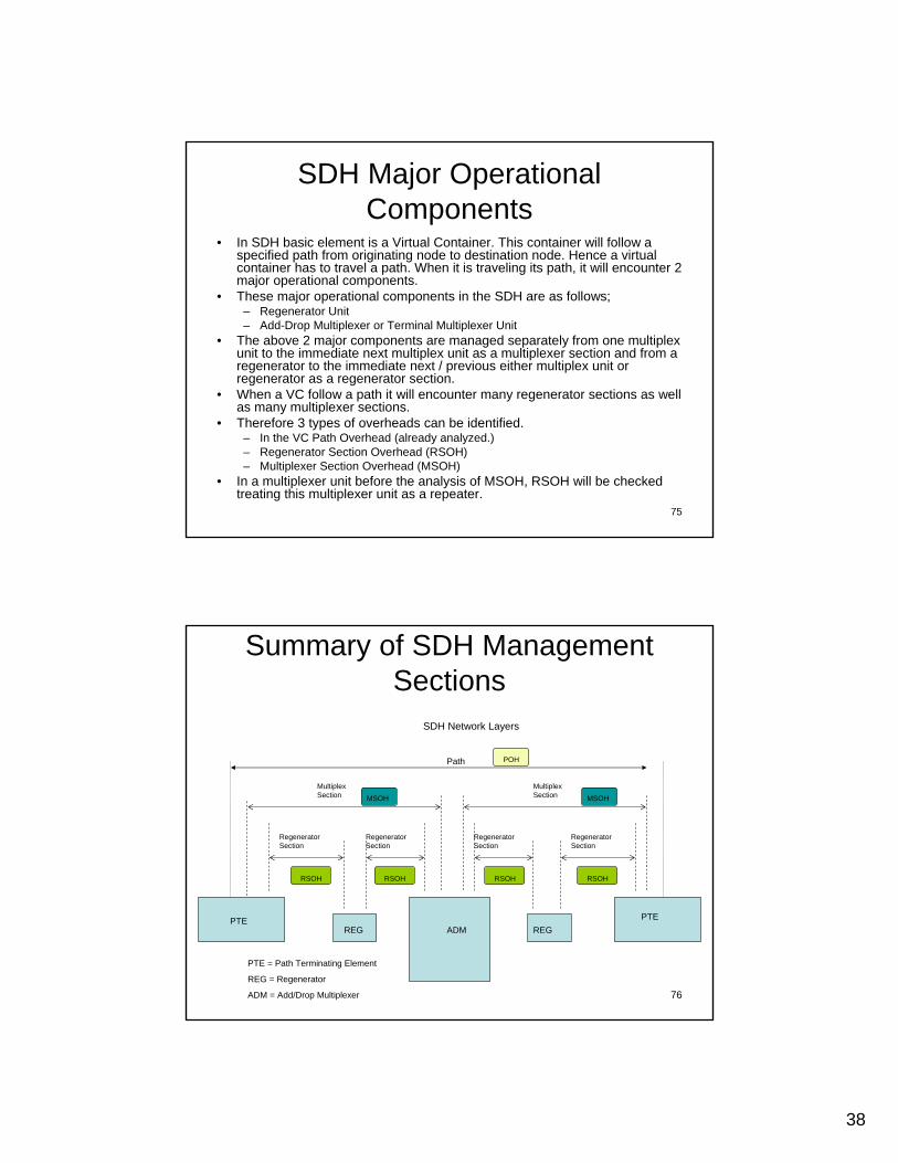
SDH Major Operational Components
• In SDH basic element is a Virtual Container. This container will follow a specified path from originating node to destination node. Hence a virtual container has to travel a path. When it is traveling its path, it will encounter 2 major operational components.
• These major operational components in the SDH are as follows;– Regenerator Unit– Add-Drop Multiplexer or Terminal Multiplexer Unit
• The above 2 major components are managed separately from one multiplex unit to the immediate next multiplex unit as a multiplexer section and from a regenerator to the immediate next / previous either multiplex unit or regenerator as a regenerator section.
• When a VC follow a path it will encounter many regenerator sections as well as many multiplexer sections.
• Therefore 3 types of overheads can be identified.– In the VC Path Overhead (already analyzed.)– Regenerator Section Overhead (RSOH)– Multiplexer Section Overhead (MSOH)
• In a multiplexer unit before the analysis of MSOH, RSOH will be checked treating this multiplexer unit as a repeater.
76
Path
REGREGPTE
ADM
Multiplex Section
Regenerator Section
Multiplex Section
Regenerator Section
Regenerator Section
Regenerator Section
SDH Network Layers
Summary of SDH Management Sections
RSOH RSOH RSOH RSOH
MSOH MSOH
POH
PTE = Path Terminating Element
REG = Regenerator
ADM = Add/Drop Multiplexer
PTE
39
77
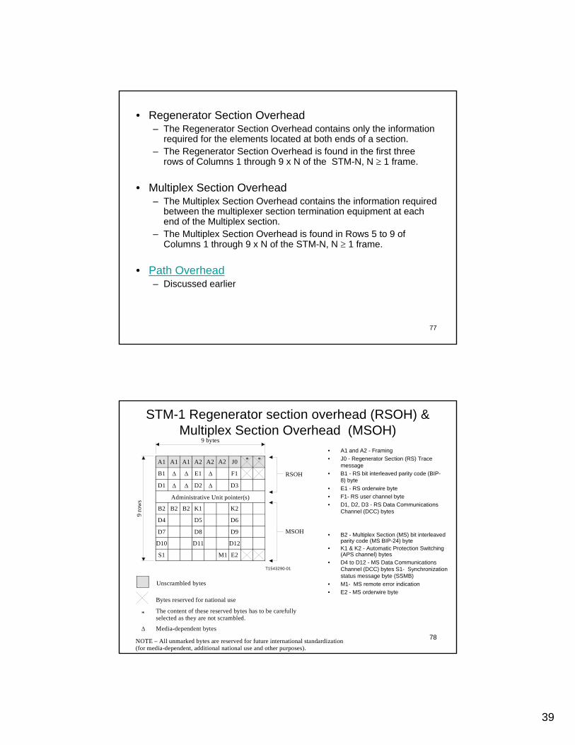
• Regenerator Section Overhead– The Regenerator Section Overhead contains only the information
required for the elements located at both ends of a section. – The Regenerator Section Overhead is found in the first three
rows of Columns 1 through 9 x N of the STM-N, N ≥ 1 frame.
• Multiplex Section Overhead– The Multiplex Section Overhead contains the information required
between the multiplexer section termination equipment at each end of the Multiplex section.
– The Multiplex Section Overhead is found in Rows 5 to 9 of Columns 1 through 9 x N of the STM-N, N ≥ 1 frame.
• Path Overhead– Discussed earlier
78
**
*
T1543290-01
∆
D12D11D10
A1
B1
D1
B2
D4
D7
S1 M1 E2
B2 B2 K1
D5
D8
K2
D6
D9
A1
∆
A1 A2 A2 A2 J0
∆
∆
∆
∆
∆
E1
D2
F1
D3
RSOH
MSOH
9 bytes
9 ro
ws
Bytes reserved for national use
The content of these reserved bytes has to be carefully selected as they are not scrambled.
Media-dependent bytes
NOTE – All unmarked bytes are reserved for future international standardization(for media-dependent, additional national use and other purposes).
Administrative Unit pointer(s)
Unscrambled bytes
STM-1 Regenerator section overhead (RSOH) & Multiplex Section Overhead (MSOH)
• A1 and A2 - Framing • J0 - Regenerator Section (RS) Trace
message• B1 - RS bit interleaved parity code (BIP-
8) byte• E1 - RS orderwire byte • F1- RS user channel byte • D1, D2, D3 - RS Data Communications
Channel (DCC) bytes
• B2 - Multiplex Section (MS) bit interleaved parity code (MS BIP-24) byte
• K1 & K2 - Automatic Protection Switching (APS channel) bytes
• D4 to D12 - MS Data Communications Channel (DCC) bytes S1- Synchronization status message byte (SSMB)
• M1- MS remote error indication• E2 - MS orderwire byte
40
79
Regenerator Section Overhead• A1 and A2 - Framing bytes – These two bytes indicate the beginning of the
STM-N frame. The A1, A2 bytes are unscrambled. A1 has the binary value 11110110, and A2 has the binary value 00101000. The frame alignment word of an STM-N frame is composed of (3 x N) A1 bytes followed by (3 x N) A2 bytes.
• J0 - Regenerator Section (RS) Trace message – It’s used to transmit a Section Access Point Identifier so that a section receiver can verify its continued connection to the intended transmitter. The coding of the J0 byte is the same as for J1 and J2 bytes.
• Z0 - These bytes, which are located at positions in STM-N signal (N > 1), are reserved for future international standardization.
• B1 - RS bit interleaved parity code (BIP-8) byte – This is a parity code (even parity), used to check for transmission errors over a regenerator section. Its value is calculated over all bits of the previous STM-N frame after scrambling, then placed in the B1 byte of STM-1 before scrambling.
• E1 - RS orderwire byte – This byte is allocated to be used as a local order wire channel for voice communication between regenerators.
• F1- RS user channel byte – This byte is set aside for the user’s purposes; it can be read and/or written to at each section terminating equipment in that line.
• D1, D2, D3 - RS Data Communications Channel (DCC) bytes – These three bytes form a 192 kbit/s message channel providing a message-based channel for Operations, Administration and Maintenance (OAM) between pieces of section terminating equipment. The channel can be used from a central location for control monitoring administration and other communication
80
Multiplex Section Overhead• B2 - Multiplex Section (MS) bit interleaved parity code (MS BIP-24) byte – This bit
interleaved parity N x 24 code is used to determine if a transmission error has occurred over a multiplex section. It’s even parity, and is calculated overall bits of the MS Overhead and the STM-N frame of the previous STM-N frame before scrambling.
• K1 and K2 - Automatic Protection Switching (APS channel) bytes – These two bytes are used for MSP (Multiplex Section Protection) signaling between multiplex level entities for bi-directional automatic protection switching and for communicating Alarm Indication Signal (AIS) and Remote Defect Indication (RDI) conditions.
K1 Byte K2 ByteBits 1-4 Type of request Bits 1-4 Selects channel number
– 1111 Lock out of Protection Bit 5 Indication of architecture– 1110 Forced Switch 0 1+1– 1101 Signal Fail – High Priority 1 1:n– 1100 Signal Fail – Low Priority Bits 6-8 Indicate mode of operation– 1011 Signal Degrade – High Priority 111 MS-AIS– 1010 Signal Degrade – Low Priority 110 MS-RDI– 1001 (not used) 101 Provisioned mode is bi-directional– 1000 Manual Switch 100 Provisioned mode is unidirectional– 0111 (not used) 011 Future use– 0110 Wait-to-Restore 010 Future use– 0101 (not used) 001 Future use– 0100 Exercise 000 Future use– 0011 (not used)– 0010 Reverse Request– 0001 Do Not Revert– 0000 No Request
Bits 5-8 Indicate the number of the channel requested
41
81
Multiplex Section Overhead (contd.)
• D4 to D12 - MS Data Communications Channel (DCC) bytes – These nine bytes form a 576 kbit/s message channel from a central location for OAM information.
• S1- Synchronization status message byte (SSMB) – Bits 5 to 8 of this S1 byte are used to carry the synchronization messages.
Bits 5-8• 0000 Quality unknown (existing sync.network)• 0010 G.811 PRC• 0100 SSU-A (G.812 transit)• 1000 SSU-B (G.812 local)• 1011 G.813 Option 1 Synchronous Equipment Timing Clock (SEC)• 1111 Do not use for synchronization.This message may be emulated by equipment failures and
will be emulated by a Multiplex Section AIS signal.
• M1- MS remote error indication – The M1 byte of an STM-1 or the first STM-1 of an STM-N is used for a MS layer remote error indication (MS-REI).
• E2 - MS orderwire byte – This orderwire byte provides a 64 kbit/s channel between multiplex entities for an express orderwire.
82
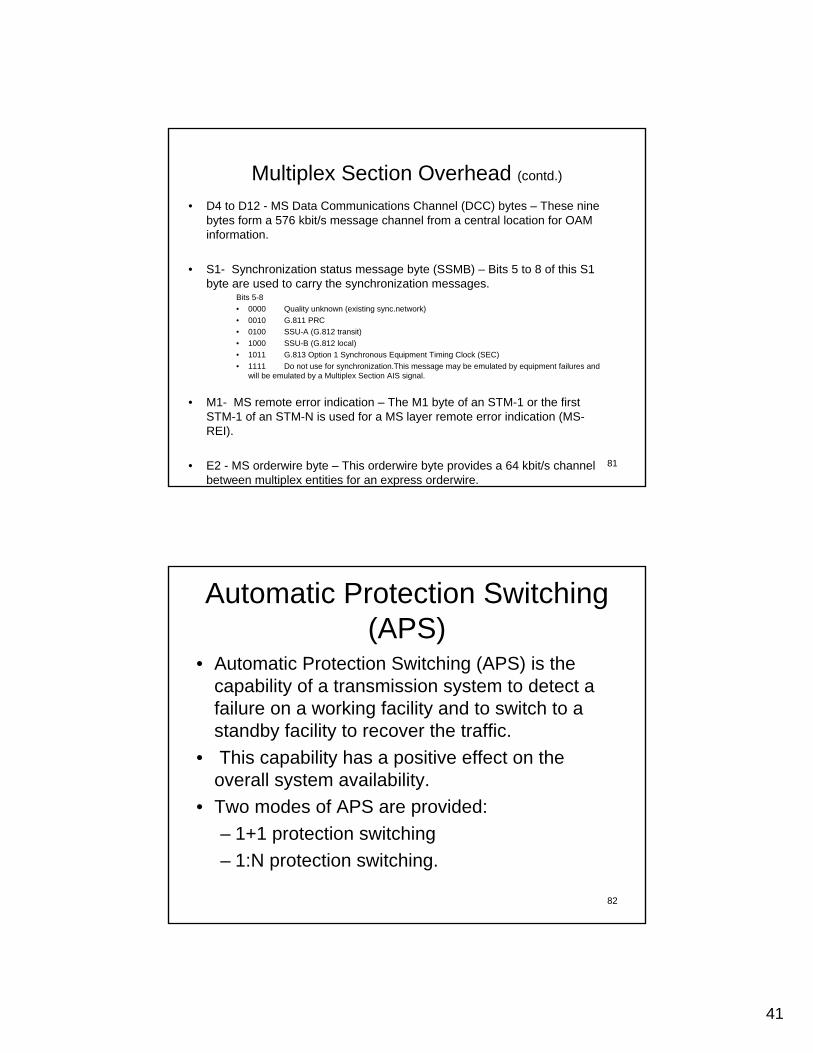
Automatic Protection Switching (APS)
• Automatic Protection Switching (APS) is the capability of a transmission system to detect a failure on a working facility and to switch to a standby facility to recover the traffic.
• This capability has a positive effect on the overall system availability.
• Two modes of APS are provided: – 1+1 protection switching– 1:N protection switching.
42
83
1+1 Protection Switching
1+ N Protection Switching
84
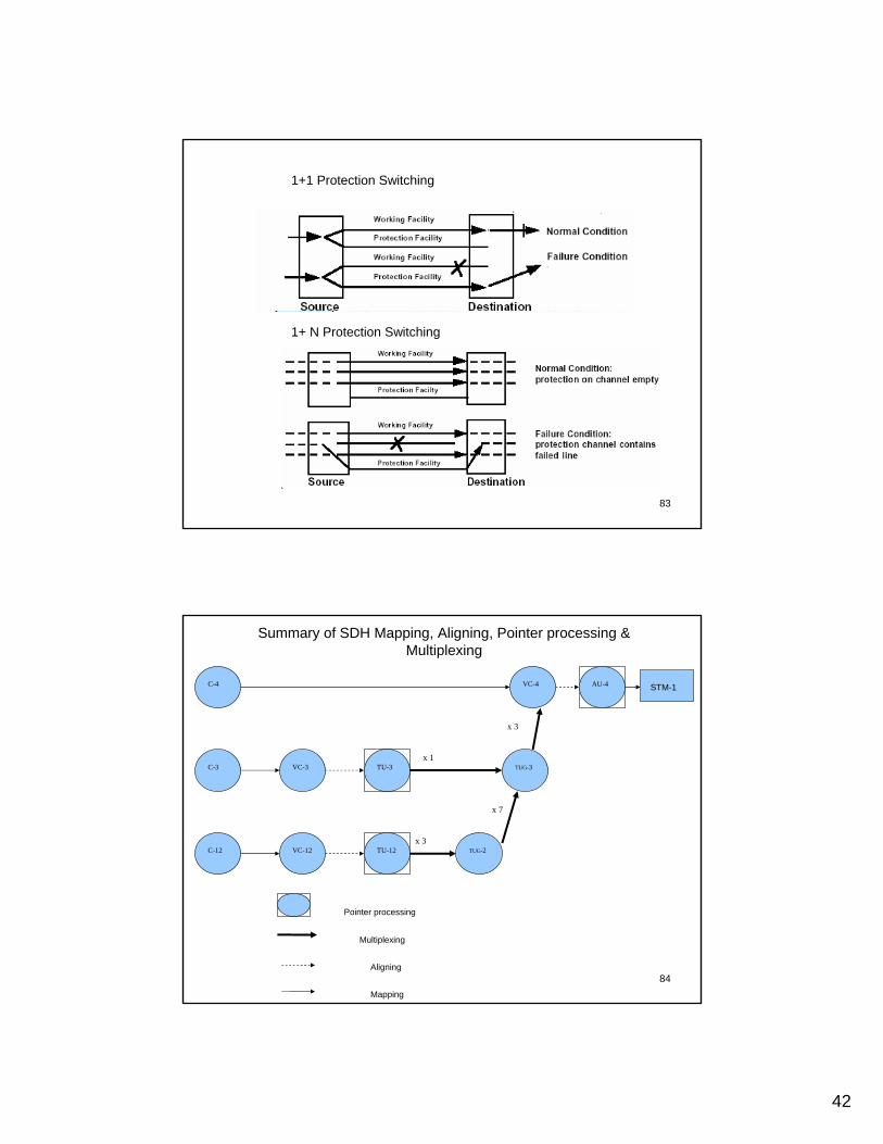
C-12 VC-12 TU-12 TUG-2
VC-3C-3 TU-3 TUG-3
C-4 VC-4 AU-4
x 3
x 1
x 7
x 3
STM-1
Pointer processing
Multiplexing
Aligning
Mapping
Summary of SDH Mapping, Aligning, Pointer processing & Multiplexing
43
85
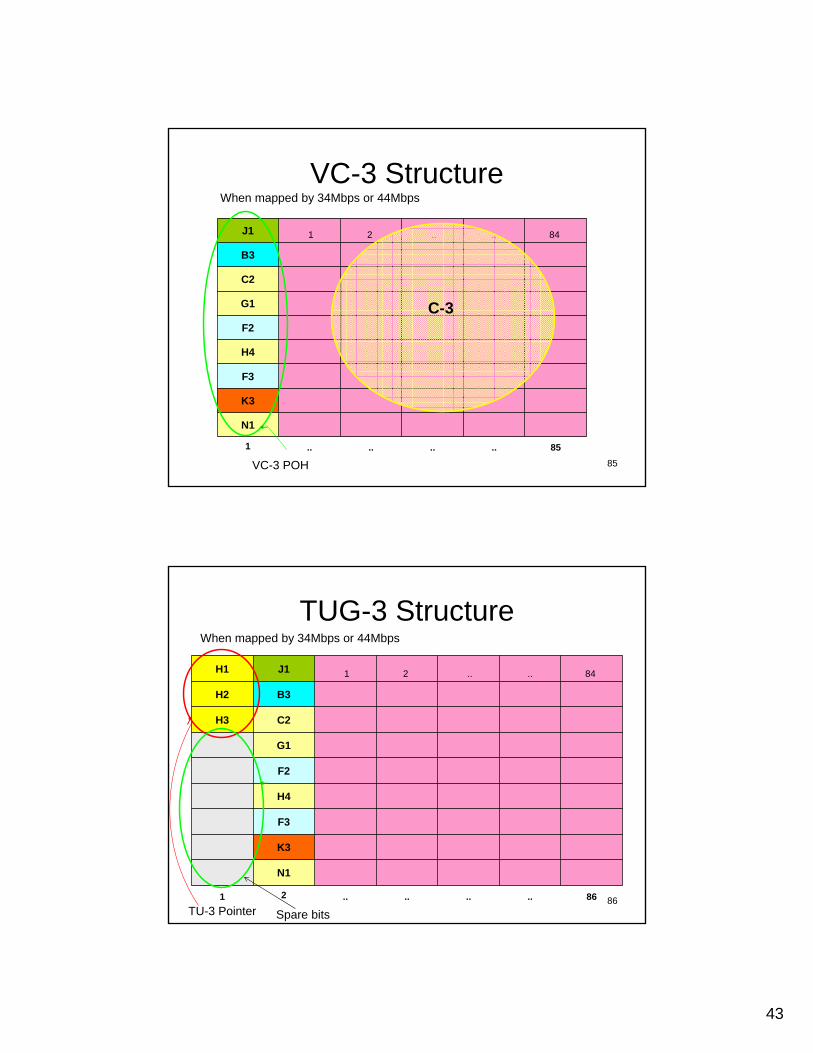
VC-3 Structure
85........1
N1
K3
F3
H4
F2
G1
C2
B3
84....21J1
VC-3 POH
C-3
When mapped by 34Mbps or 44Mbps
86
TUG-3 StructureWhen mapped by 34Mbps or 44Mbps
86........21
N1
K3
F3
H4
F2
G1
C2H3
B3H2
84....21J1H1
TU-3 Pointer Spare bits
44
87
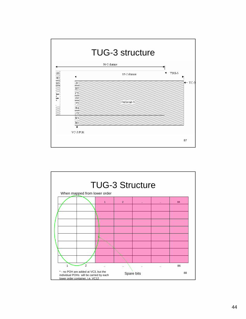
TUG-3 structure
88
TUG-3 Structure
86........21
84....21
When mapped from lower order
Spare bits* - no POH are added at VC3, but the individual POHs will be carried by each lower order container, i.e. VC12
45
89
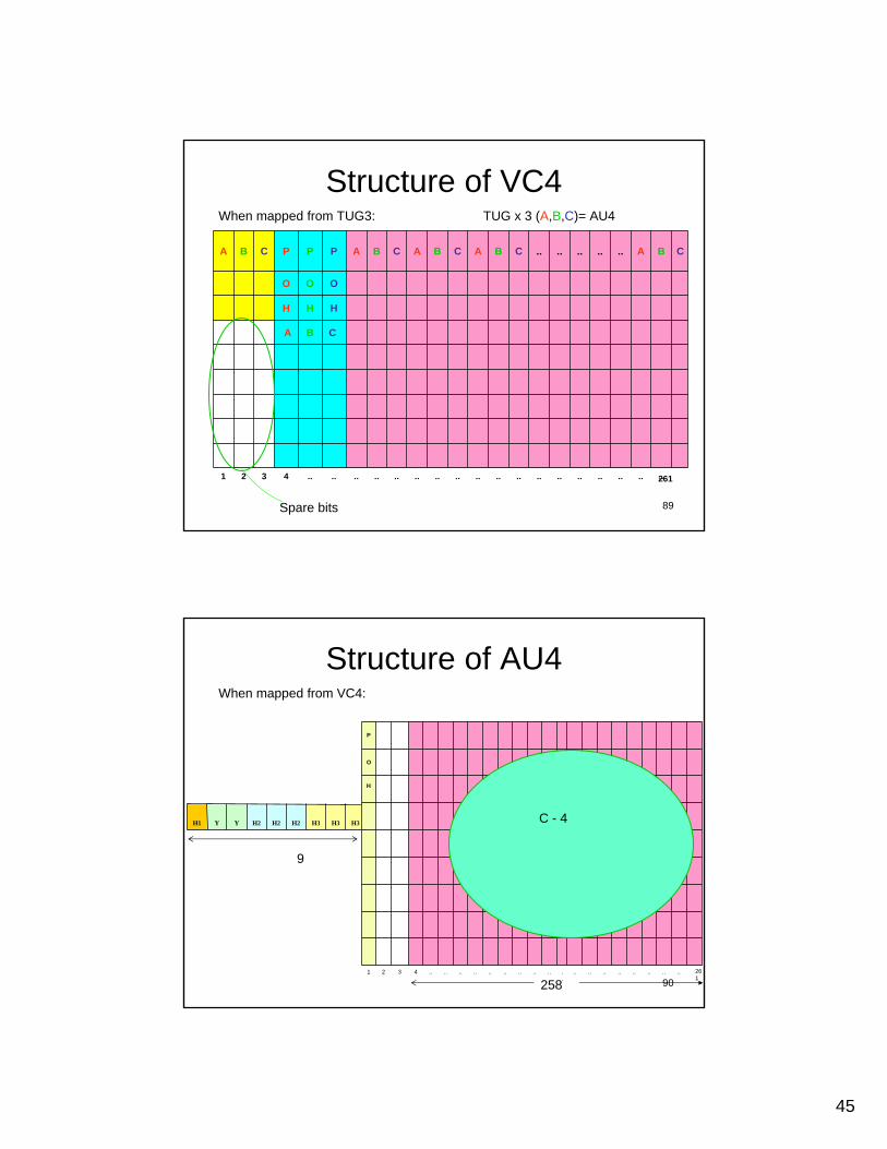
Structure of VC4
....................................4321
CBA
HHH
OOO
CBA..........CBACBACBAPPPCBA
261
When mapped from TUG3: TUG x 3 (A,B,C)= AU4
Spare bits
90
Structure of AU4When mapped from VC4:
H3H3H3H2H2H2YYH1
258261
..................
..................4321
H
O
P
C - 4
9
46
91
Examples of SDH Networks
92
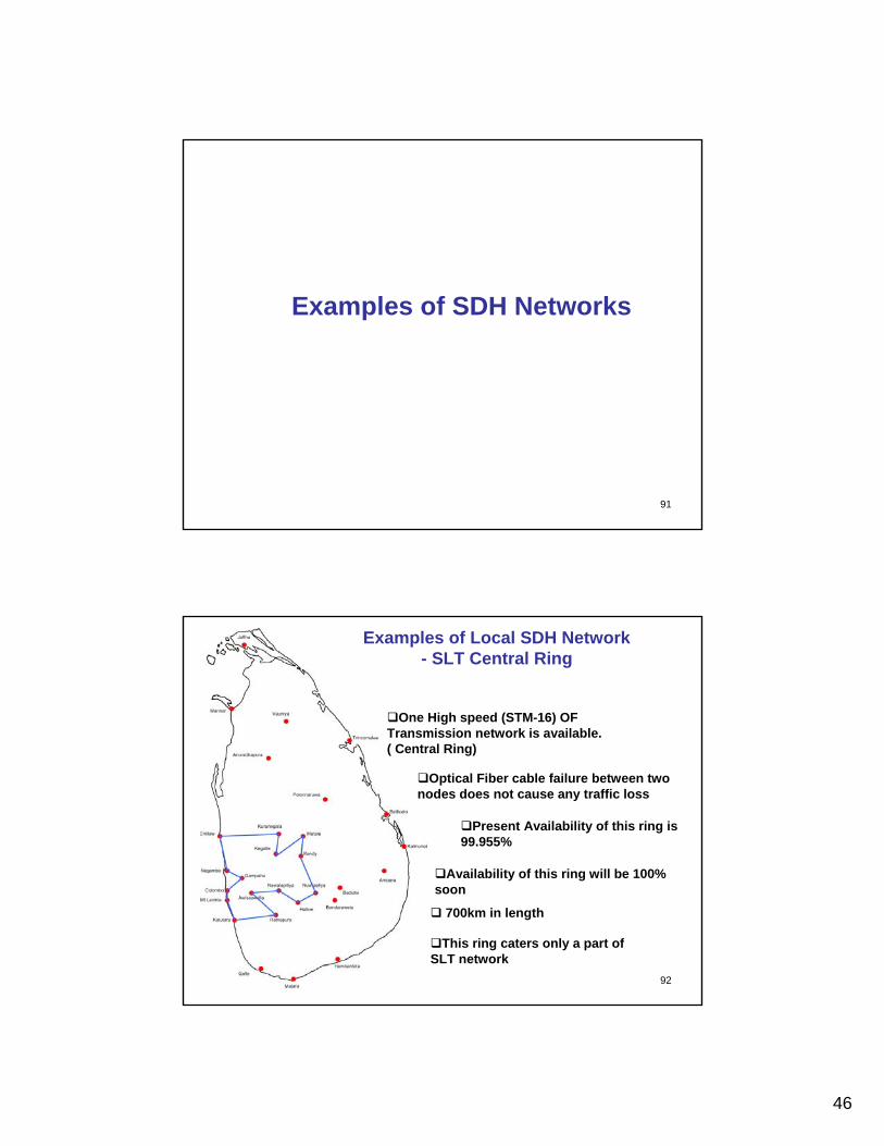
Examples of Local SDH Network- SLT Central Ring
One High speed (STM-16) OF Transmission network is available. ( Central Ring)
This ring caters only a part of SLT network
Optical Fiber cable failure between two nodes does not cause any traffic loss
Present Availability of this ring is 99.955%
Availability of this ring will be 100% soon
700km in length

47
93
Path Protection
F
E
B
C
A
D
Both working and protection fiber cut at one place
Automatic restoration from the protection fiber by two steps at B and C which show below
Principle of Self-Healing in an SDH Ring Network
94
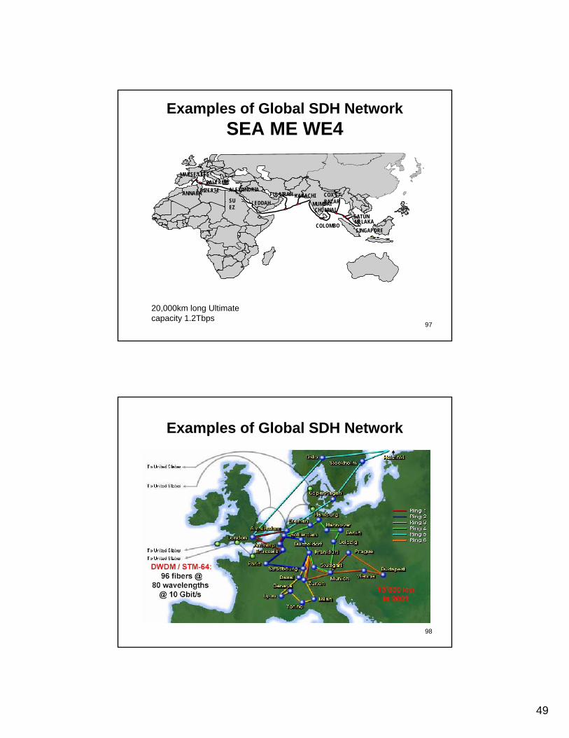
Examples of Global SDH NetworkKPNQwest EuroRings Network
13,000 km in 2001
To United States
To United States
DWDM / STM-64:96 fibers @80 wavelengths@ 10 Gbit/s

48
95
Examples of Global SDH NetworkQwest Unified Global Broadband Network
96
Examples of Global SDH NetworkSEA ME WE3
40 landing points in 34 countries 39,000km in length
Initially @2.5Gbps, Upgraded to 20Gbps in 2000
49
97
Examples of Global SDH NetworkSEA ME WE4
MUMBAIKARACHIFUJAIRAH
COLOMBO
CHENNAI
COX’S BAZARSU
EZJEDDAH
MARSEILLESPALERMO
ALEXANDRIA
MELAKASINGAPORE
BIZERTEBIZERTE
SATUNSATUN
ANNABAANNABA
20,000km long Ultimate capacity 1.2Tbps
98
Examples of Global SDH Network

50
99
Examples of Global SDH Network
100