revista ingeniería de construcción ric vol 34 nº3 2019 www
TRANSCRIPT

Revista Ingeniería de Construcción RIC Vol 34 Nº3 2019 www.ricuc.cl
ENGLISH VERSION.....................................................................................................................................................................................................................................................
252 Revista Ingeniería de Construcción Vol 34 Nº3 Diciembre de 2019 www.ricuc.cl
Retaining Wall based on mechanically stabilized tire stack Muro de contención construido con neumáticos estabilizados mecánicamente
P. Barros *, G. Sarabia *, F. Valdés 1*, P. Serrano *, I. Gaytan *
* Universidad Técnica Federico Santa María – Valparaiso, CHILE
Fecha de Recepción: 10/01/2019 Fecha de Aceptación: 15/05/2019
PAG 252-267
Abstract In the last great fire of 2014 that affected Valparaíso, numerous building and structural deficiencies about slope construction were found. This issue was a significant factor in the number of homes destroyed. Then, the motivation arises to develop inexpensive retaining wall technologies, structurally validated, that can be implemented by people without greater technical knowledge. In parallel, Chile has a fleet close to 5,000,000 vehicles (INE, 2017). This means a potential replacement of 20,000,000 tires in 4 or 5 years, transforming them into an abundant and environmentally persistent volumetric residue, which accumulates especially in the gorges of Valparaíso. In this context, and as the first objective of this research, we identify the opportunity to contain landfills with recycled tire structures. In the present work, a vision about the state of international, national and local art about retaining wall with tires is shown and examples are presented. Then, exploratory proposals are developed, which finally settle in a definitive proposal of a retaining wall with mechanically stabilized tires. This proposal was submitted to structural calculation according to current engineering criteria, to lastly recommend it as a valid option for containing a horizontal plane with satisfactory building standards.
Keywords: Retaining wall, tires, mechanically stabilized earth (MSE), craft construction Resumen En el último gran incendio que afectó a Valparaíso el año 2014 quedaron al descubierto muchas deficiencias, tanto estructurales como constructivas, sobre la edificación en pendiente, factores que fueron determinantes en la cantidad de viviendas destruidas. De ahí surgió la motivación para desarrollar tecnologías económicas para los muros de contención, que fueran estructuralmente válidas y pudieran ser implementadas por personas sin mayores conocimientos técnicos. Por otra parte, el año 2015, Chile contaba con una flota de unos 5.000.000 vehículos (INE, 2017). Esto significa que existe un potencial de 20 millones de neumáticos de desecho acumulables en un periodo de entre 4 a 5 años, volumen que se transforma en un residuo abundante y persistente para el medio ambiente, y que se acumula principalmente en las quebradas entre los cerros de Valparaíso. En este contexto identificamos como principal objetivo de esta investigación, la oportunidad de contener los rellenos de tierra con estructuras construidas con neumáticos de desecho. Este trabajo presenta una visión del estado internacional, nacional y local de los muros de contención construidos con neumáticos y algunos ejemplos. Se desarrollaron algunas propuestas exploratorias que derivaron finalmente en la definitiva: un muro de contención construido con neumáticos estabilizados mecánicamente. Esta propuesta se sometió al cálculo estructural de acuerdo a los criterios ingeneriles vigentes, para finalmente recomendarla como una opción válida de retener un plano horizontal bajo estándares constructivos satisfactorios. Palabras clave: Muro de contención, neumáticos, tierra estabilizada mecánicamente (TEM), construcción artesanal
1. Introduction
Valparaíso is a city that -from its origins- has grown as an amphitheater on the slopes of its hills, ranging from sea level to about 300 meters, in almost 8 km horizontal. As
shown in the diagrams of (Figure 1), its inhabitants have developed a culture and skill on how to achieve the horizontal in steep terrain.
1 1 Corresponding author: Universidad Técnica Federico Santa María – Valparaiso, CHILE E-mail: [email protected]

Revista Ingeniería de Construcción RIC Vol 34 Nº3 2019 www.ricuc.cl
ENGLISH VERSION.....................................................................................................................................................................................................................................................
Revista Ingeniería de Construcción Vol 34 Nº3 Diciembre de 2019 www.ricuc.cl 253
After the fire that occurred in April 2014 -which affected mostly peripheral and socioeconomically vulnerable neighborhoods (Barrales, 2017) - it was easy to compare the damage between those houses close to the belt road, which were built on stabilized floors with retaining walls, to those that were built on land supported only on wooden pillars directly to the ground: the first suffered damage, but not at the level of destruction and collapse that affected the second.
When observing Valparaíso from sea to hill, with its slopes and ravines, evidence of different types of retaining
walls, according to their different periods of development, can be seen. The gravitational type -based on granite stone masonry- was the more frequent until the middle of the last century (Hurtado et al., 2016). This technique was gradually abandoned by the builders. One explanation of this phenomenon is -mainly- the increased cost of raw materials, and the disappearance of specialized labor due to the rise of reinforced concrete.
Figure 1. Schemes of traditional forms to obtain the horizontal in Valparaíso (Drawings: L. Pablo Barros)
Revista Ingeniería de Construcción RIC Vol 34 Nº3 2019 www.ricuc.cl
ENGLISH VERSION.....................................................................................................................................................................................................................................................
254 Revista Ingeniería de Construcción Vol 34 Nº3 Diciembre de 2019 www.ricuc.cl
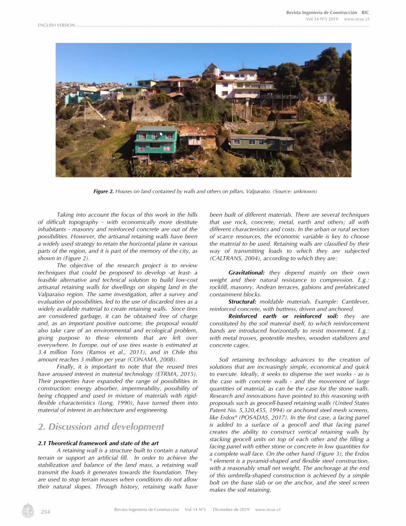
Taking into account the focus of this work in the hills of difficult topography - with economically more destitute inhabitants - masonry and reinforced concrete are out of the possibilities. However, the artisanal retaining walls have been a widely used strategy to retain the horizontal plane in various parts of the region, and it is part of the memory of the city, as shown in (Figure 2).
The objective of the research project is to review techniques that could be proposed to develop -at least- a feasible alternative and technical solution to build low-cost artisanal retaining walls for dwellings on sloping land in the Valparaíso region. The same investigation, after a survey and evaluation of possibilities, led to the use of discarded tires as a widely available material to create retaining walls. Since tires are considered garbage, it can be obtained free of charge and, as an important positive outcome, the proposal would also take care of an environmental and ecological problem, giving purpose to these elements that are left over everywhere. In Europe, out of use tires waste is estimated at 3.4 million Tons (Ramos et al., 2011), and in Chile this amount reaches 3 million per year (CONAMA, 2008).
Finally, it is important to note that the reused tires have aroused interest in material technology (ETRMA, 2015). Their properties have expanded the range of possibilities in construction: energy absorber, impermeability, possibility of being chopped and used in mixture of materials with rigid-flexible characteristics (Long, 1990), have turned them into material of interest in architecture and engineering.
2. Discussion and development 2.1 Theoretical framework and state of the art
A retaining wall is a structure built to contain a natural terrain or support an artificial fill. In order to achieve the stabilization and balance of the land mass, a retaining wall transmit the loads it generates towards the foundation. They are used to stop terrain masses when conditions do not allow their natural slopes. Through history, retaining walls have
been built of different materials. There are several techniques that use rock, concrete, metal, earth and others; all with different characteristics and costs. In the urban or rural sectors of scarce resources, the economic variable is key to choose the material to be used. Retaining walls are classified by their way of transmitting loads to which they are subjected (CALTRANS, 2004), according to which they are:
Gravitational: they depend mainly on their own
weight and their natural resistance to compression. E.g.: rockfill, masonry, Andean terraces, gabions and prefabricated containment blocks.
Structural: moldable materials. Example: Cantilever, reinforced concrete, with buttress, driven and anchored.
Reinforced earth or reinforced soil: they are constituted by the soil material itself, to which reinforcement bands are introduced horizontally to resist movement. E.g.: with metal trusses, geotextile meshes, wooden stabilizers and concrete cages.
Soil retaining technology advances to the creation of
solutions that are increasingly simple, economical and quick to execute. Ideally, it seeks to dispense the wet works - as is the case with concrete walls - and the movement of large quantities of material, as can be the case for the stone walls. Research and innovations have pointed to this reasoning with proposals such as geocell-based retaining walls (United States Patent No. 5,320,455, 1994) or anchored steel mesh screens, like Erdox® (POSADAS, 2017). In the first case, a facing panel is added to a surface of a geocell and that facing panel creates the ability to construct vertical retaining walls by stacking geocell units on top of each other and the filling a facing panel with either stone or concrete in low quantities for a complete wall face. On the other hand (Figure 3), the Erdox ® element is a pyramid-shaped and flexible steel construction, with a reasonably small net weight. The anchorage at the end of this umbrella-shaped construction is achieved by a simple bolt on the base slab or on the anchor, and the steel screen makes the soil retaining.
Figure 2. Houses on land contained by walls and others on pillars, Valparaíso. (Source: unknown)

Revista Ingeniería de Construcción RIC Vol 34 Nº3 2019 www.ricuc.cl
ENGLISH VERSION.....................................................................................................................................................................................................................................................
Revista Ingeniería de Construcción Vol 34 Nº3 Diciembre de 2019 www.ricuc.cl 255
2.2 Use of tires in civil works
The use of tires in civil works has been investigated for decades. The first data are recorded in France in 1976 (Long, 1990). In 1990, Nguyen Thanh Long, publishes Pneusol, where it collects studies on the soil-pneumatic combination and its application to civil works, stabilizing slopes and soil reinforcement, until its use in the construction of roads. This technique has been used in various parts of the world, with satisfactory results.
Discarded tires abound throughout the planet and it is possible to find examples of their use in containments in many countries. It is the most abundant volumetric waste in the vicinity of urban areas. Tires are a piece of technology that only uses its external rolling band, which leaves 90% of its total structure intact.
2.3 Retaining walls with tires This system consists in the use of discarded tires as
containment and / or reinforcement elements. The tires can be used complete or cut. they are joined together forming continuous horizontal layers, which are superimposed to form the wall with their intended dimensions.
The constructive technology of containing soil with tires is not rare to the region of Valparaíso, and it is possible to find cases of old handcrafted walls that continue to serve today. 2.4 Wall with tires and horizontal engagement
(Figure 4) shows a wall that has 9 layers or rows, so it is estimated that its height is about 1.80 m. This is especially interesting because of the proximity of the two-story house.
Figure 3. Erdox ® system. (Source: Betonform LA)

Revista Ingeniería de Construcción RIC Vol 34 Nº3 2019 www.ricuc.cl
ENGLISH VERSION.....................................................................................................................................................................................................................................................
256 Revista Ingeniería de Construcción Vol 34 Nº3 Diciembre de 2019 www.ricuc.cl
2.5 Wall with tires supported by stone masonry
(Figure 5) shows a wall of a height close to 4 m, built on stone masonry. As seen in detail of (Figure 5), the masonry serves as a way to level the basement of the wall. It can also
be estimated that the vegetation that has grown between the tires may be acting as a reinforcement, helping to withstand the push of the ground. However, this assumption requires a specific study.
Figure 4. Retaining wall in Cerro Las Cañas, Valparaíso. (Photo courtesy of Claudio Peña)
Figure 5. Retaining wall in the La Vega sector, Olmué. (Photography: courtesy of Tania Estay)

Revista Ingeniería de Construcción RIC Vol 34 Nº3 2019 www.ricuc.cl
ENGLISH VERSION.....................................................................................................................................................................................................................................................
Revista Ingeniería de Construcción Vol 34 Nº3 Diciembre de 2019 www.ricuc.cl 257
The wall depicted in (Figure 6), presents the tires
arranged in piles with some inclination towards the contained terrain, and with its rows overlapped in the upper level.
2.6 Retaining walls with modified tires - Yantek Method
An interesting case to consider is the Yantek company in Mexico. As noted in the contractor's report to the California Board for Integrated Waste Management, CIWMB, the system "can be anchored and secured to the slopes for stability and is suitable for use in steep cuts of roads that are characteristic in road construction in Baja California" (CIWMB, 2009). They build walls with modified tires by cutting the lateral faces off the tire bands with special machinery. Then, the band is turned inward, leaving its inner face outward, thus generating
a rubber unit called “8”, because of its shape (Figure 7); the union of several "8" is a "mat", which are filled with compacted soil. Then, they used the tire sides in the back of the wall. A row is offset by about 5 cm, which creates an inclination of about 70 ° in front of the system, as shown in (Figure 8). The space of 5 cm can be used for plants. This system does not generate waste and works by gravity. They are heavy, flexible and draining. They also have a large base, which constitutes 60% of the height of the wall. This wall system is anchored to the slope and the ground.
Figure 6. Medialuna retaining wall of "La Dormida", Olmué. (Photo: Gustavo Sarabia)
Figure 7. Tire modification result (Photo: www.yantek.com)

Revista Ingeniería de Construcción RIC Vol 34 Nº3 2019 www.ricuc.cl
ENGLISH VERSION.....................................................................................................................................................................................................................................................
258 Revista Ingeniería de Construcción Vol 34 Nº3 Diciembre de 2019 www.ricuc.cl
2.7 Retaining walls with discarded tires
Chile has a current fleet of 4.960.945 cars, which means a potential of 20,000,000 discarded tires in 4 to 5 years (INE, 2017). Then, tires are the most abundant and environmentally persistent volumetric waste around cities. From the above, it emerges the interest of finding ways to
reuse tires in the attainment of flat lands for construction. In this case, the use of tires for molding the topography appears to be appropriate; given the availability of material and the construction speed that a containment wall can achieve with local labor and unsophisticated tools.
Figure 9. Explanatory diagram symbology of a tire. (Drawing: L. Pablo Barros)
Figure 8. Yantek system retaining wall completed (Photo: www.yantek.com)

Revista Ingeniería de Construcción RIC Vol 34 Nº3 2019 www.ricuc.cl
ENGLISH VERSION.....................................................................................................................................................................................................................................................
Revista Ingeniería de Construcción Vol 34 Nº3 Diciembre de 2019 www.ricuc.cl 259
3. Retaining walls with tires: Exploratory proposals
By studying the previous art, several ways of constructing retaining walls with tires can be recognized. These systems use tires either in their original form or intervened with industrial processes, in simple support systems or with some type of reinforcement. They can be filled with earth or simply chaining them to form a flexible mesh that works on traction.
The design restrictions were established based on the contextual conditions. To design a retaining wall based on tires, suitable for use in the topography of Valparaíso, with artisanal execution, simple construction, low cost, in which a safe structural operation can be previously validated by
calculation, the set criteria is proposed as follows:
• Wall with tires suitable to contain soil fill and not slope cut.
• Construction height of 3 m, measured from NTN (natural terrain level).
• Wall width equivalent to the outside diameter of a tire with measures 185 / 60R14 (Figure 9).
• Use of waste tires without intervention (disband or cut).
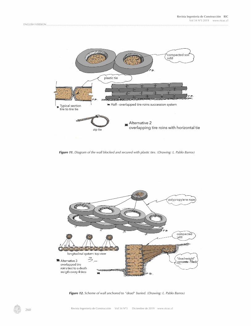
In (Figure 10), (Figure 11) y (Figure 12), three of the evaluated hypotheses are shown.
Figure 10. Wall diagram of tires filled with earth and post-compressed. (Drawing: L. Pablo Barros)
Revista Ingeniería de Construcción RIC Vol 34 Nº3 2019 www.ricuc.cl
ENGLISH VERSION.....................................................................................................................................................................................................................................................
260 Revista Ingeniería de Construcción Vol 34 Nº3 Diciembre de 2019 www.ricuc.cl
Figure 12. Scheme of wall anchored to "dead" buried. (Drawing: L. Pablo Barros)
Figure 11. Diagram of the wall blocked and secured with plastic ties. (Drawing: L. Pablo Barros)
Revista Ingeniería de Construcción RIC Vol 34 Nº3 2019 www.ricuc.cl
ENGLISH VERSION.....................................................................................................................................................................................................................................................
Revista Ingeniería de Construcción Vol 34 Nº3 Diciembre de 2019 www.ricuc.cl 261
3.1 Tire-based retaining wall mechanically stabilized
In order to choose the most suitable proposal to be further, a final restriction was critical: it was established not to use foundations dug out of medium depth for the support of the wall. This requirement was established due to excavating and concreting a foundation implies an increase in costs and greater difficulty of construction (materials, machinery, accessibility). This last condition revealed the need to analogically adopt the constructive and structural system of Mechanically Stabilized Earth (TEM) walls. In the "Bridge Design Specifications - Section 5 - Retaining Walls" is defined as: Earthen walls that use reinforcement of metallic (inextensible) or geosynthetic (extendable) soil in the soil mass, and vertical or almost vertical coating elements"
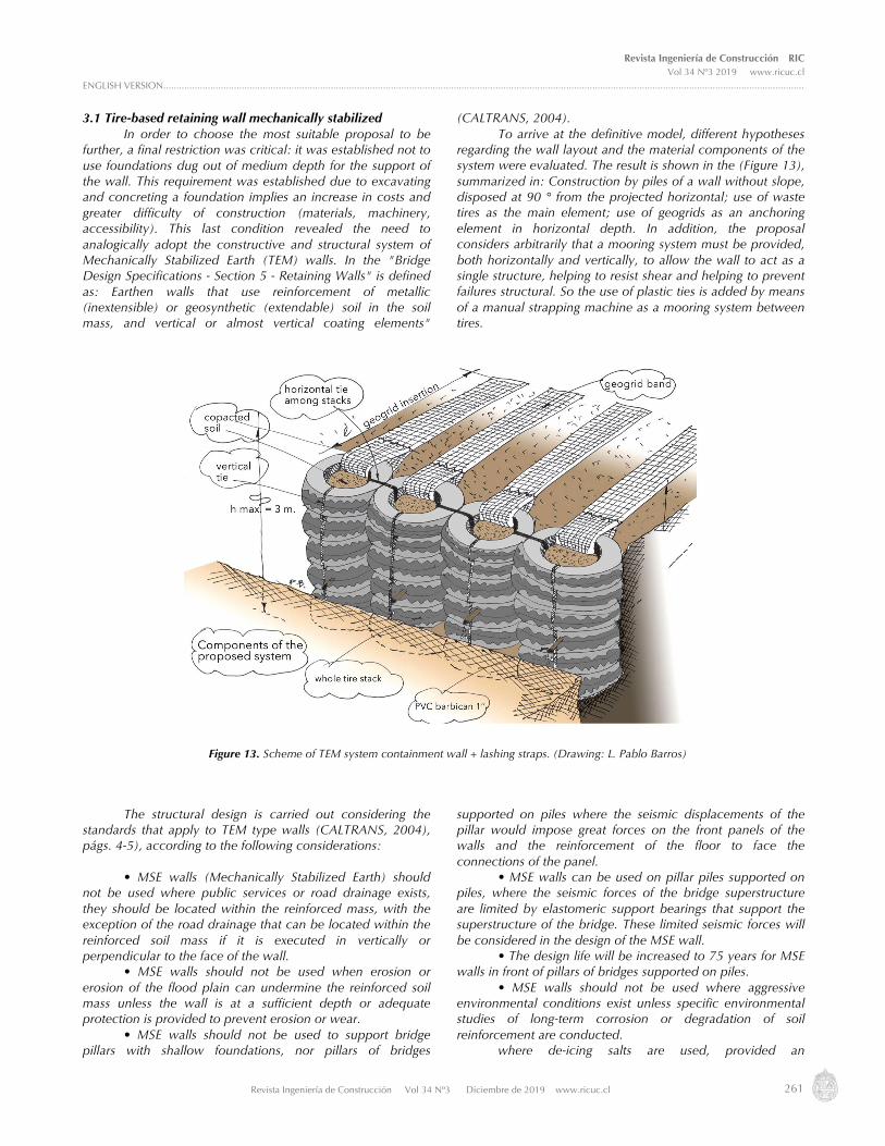
(CALTRANS, 2004). To arrive at the definitive model, different hypotheses
regarding the wall layout and the material components of the system were evaluated. The result is shown in the (Figure 13), summarized in: Construction by piles of a wall without slope, disposed at 90 ° from the projected horizontal; use of waste tires as the main element; use of geogrids as an anchoring element in horizontal depth. In addition, the proposal considers arbitrarily that a mooring system must be provided, both horizontally and vertically, to allow the wall to act as a single structure, helping to resist shear and helping to prevent failures structural. So the use of plastic ties is added by means of a manual strapping machine as a mooring system between tires.
The structural design is carried out considering the standards that apply to TEM type walls (CALTRANS, 2004), págs. 4-5), according to the following considerations:
• MSE walls (Mechanically Stabilized Earth) should
not be used where public services or road drainage exists, they should be located within the reinforced mass, with the exception of the road drainage that can be located within the reinforced soil mass if it is executed in vertically or perpendicular to the face of the wall.
• MSE walls should not be used when erosion or erosion of the flood plain can undermine the reinforced soil mass unless the wall is at a sufficient depth or adequate protection is provided to prevent erosion or wear.
• MSE walls should not be used to support bridge pillars with shallow foundations, nor pillars of bridges
supported on piles where the seismic displacements of the pillar would impose great forces on the front panels of the walls and the reinforcement of the floor to face the connections of the panel.
• MSE walls can be used on pillar piles supported on piles, where the seismic forces of the bridge superstructure are limited by elastomeric support bearings that support the superstructure of the bridge. These limited seismic forces will be considered in the design of the MSE wall.
• The design life will be increased to 75 years for MSE walls in front of pillars of bridges supported on piles.
• MSE walls should not be used where aggressive environmental conditions exist unless specific environmental studies of long-term corrosion or degradation of soil reinforcement are conducted. where de-icing salts are used, provided an
Figure 13. Scheme of TEM system containment wall + lashing straps. (Drawing: L. Pablo Barros)

Revista Ingeniería de Construcción RIC Vol 34 Nº3 2019 www.ricuc.cl
ENGLISH VERSION.....................................................................................................................................................................................................................................................
262 Revista Ingeniería de Construcción Vol 34 Nº3 Diciembre de 2019 www.ricuc.cl
impermeable plug is built on or near the soil surface above the soil reinforcement and proper control of surface runoff.
Among the main queries about the systems to be answered by engineering calculation, are: How many rows of tires should install the geogrid to meet the structural feasibility? What depth of insertion should have the "band" of geogrid? and what should be the maximum height to keep only one row of tires as the total width?
To answer these questions, we take into account two of the main design requirements, which are: The systems have to use a single line of tires and the materials must be economical for their construction to be practical.
4. Calculation of structural feasibility for the proposed retaining Wall
To answer the design questions allowing comparison and verification within a known theoretical framework, the Highway Manual, Ed. 2016, vol. 3, of the Direction of Roads (MC V3), (Chile. Dirección de vialidad, 2016) AASHTO standard, section 5 was used.
The methods for the determination of the earth pressure for the design of these containment structures are based mainly on the classical theories of Rankine and Coulomb earth thrust, considering the Mononobe (Mononobe, 1925) and Okabe theory (Okabe, 1924) for the seismic case.
For the proposed retaining wall, calculations for Mechanically Stabilized Earth (TEM) with structurally collaborative layers were analogously considered. These structurally collaborative layers belong to a special category of flexible walls with gravitational contribution. Their dimensions, frequently, consider that the length must be greater than the height in at least 10%. So, these structures usually occupy a lot of space. 4.1 Calculation Parameters
The established parameters were:
Seismic factors The wall design was projected for the city of
Valparaíso. According to the norm NCh433 Of.1966 Mod.2012, the seismic zone corresponds to 3, with a coefficient of acceleration value of 0.4 (INN, 2012). In this way, the seismic coefficient that was used in the design is 0.2 for the horizontal case, while, for the vertical seismic coefficient, it is considered null, according to MC V3.
Geometric factors
- H: Height of wall (m) - L: Wall width and reinforcement length (m)
Design Loads • Dead Load: Corresponds to own weight of the
elements by their dimensions, where the specific weight of the materials was considered (γ).
• Filler loads: It was considered the one that exerts both the filling that forms the wall and the filling behind it.
• Hydrostatic loads: Corresponds to those loads generated by water on the structure.
• Earth pressure: The soil or filling material adjacent to the retaining wall, exerts on it a force that tends to overturn or slide it to the outside. The efforts considered in the lateral push are the active thrust along with their respective dynamic increase, where the cohesion and the angle of friction between the wall and the filling were considered null, this because the cohesion is an unknown property and can be degraded, so it is not considered in the design; regarding the angle of friction, because this aspect is not controlled in the construction.
• Seismic action: The soil structure interaction was considered, and the conditions of dynamic equilibrium must be fulfilled. The hypotheses and expressions of Mononobe and Okabe were used to determine these thrusts on the containment structures.
External Stability Analysis
The external stability analysis was determined by: • Earth pressure: Static; moments of the push around
the base of the wall; dynamic increments; moments of dynamic increments around the base of the wall; moment of seismic action acting as a result of weight and surcharge forceon the wall.
• Sliding stability: Safety factor for static case and seismic case (horizontal component only).
• (Overturning): Safety factor for static case and seismic case.
• (Bearing)capacity: Both for the static case and seismic case, it is important not to build in mud, dumps or loose fill to fulfill this condition.
Internal Stability Analysis
The internal stability analysis was determined by: •Tension failure: For both static and seismic, care
must be taken that the tension in each horizontal reinforcement of the wall does not exceed the last value of tensile strength corresponding to the material.
• Pull-out failure: It occurs when one of the reinforcements is not able to withstand the stresses to which it is subjected and detaches towards the outside. For both static and seismic, it must be ensured that the reinforcement has an adequate anchor length to provide in the resistance zone. 4.2 Explanation of calculation results
Once the calculations were made to evaluate the structural feasibility of the proposed wall, the results revealed that it is feasible to foresee a good structural behavior in a retaining wall built in a traditional way: with waste tires as an exterior face, with horizontal reinforcements using "bands" of geogrid, and under the TEM structural typology.
In general, the results showed that, in many cases, there was a pull-out type failure. However, this condition was allowed due to during calculations the mooring between tires was not considered in both horizontal and vertical direction. Thus, this condition effectively provides greater resistance against this type of failure.
On the following questions on construction design: How many rows of tires should the geogrid be installed to comply with structural feasibility requirements? How deep

Revista Ingeniería de Construcción RIC Vol 34 Nº3 2019 www.ricuc.cl
ENGLISH VERSION.....................................................................................................................................................................................................................................................
Revista Ingeniería de Construcción Vol 34 Nº3 Diciembre de 2019 www.ricuc.cl 263
should the geogrid "band" be? They are answered in (Table 1) for different types of overload and water column height
conditions, keeping a constant height of 3 m.
To assess the behavior of these walls, a statistical analysis of sensitivity is performed. through this analysis, it is found that one of the most influential factors for the system is the level of the water table behind the wall. In (Figure 14), it is shown that for walls of 3 (m) and with an overload of 8 (kN/m2), the required reinforcement length increases considerably as the level of water behind the wall increases. For this reason, an adequate drainage system should be considered to evacuate water that can accumulate, for example, due to heavy rains.
Regarding the question: what should be the maximum height of the wall to keep only one row of tires as total width?
The maximum height of the wall does not depend solely on the number of rows factor. The height could be increased by providing greater amount of reinforcement so that the required strength is met. However, restrictions should be considered with respect to the height-to-length ratio of the wall, which frequently has a relation L = 1.1 times the height, occupying a lot of space. (Table 2) was built, under similar conditions as the previous one, to evaluate the minimum and maximum reasonable heights for the type of wall designed; However, when determining a pull-out failure tendency and not considering the possible contribution of the vertical and horizontal ties between the tires, it is advisable to maintain a conservative height range, recommending a maximum of 3 m wall height.
Table 1. Determination of the length of reinforcements and vertical spacing for 3 m walls
Soil Properties Specific Weight 18 (kN/m3) Cohesion 0 (kN/m2) Internal friction angle 30 (º) Friction angle between filling and wall 0 (º) Seismic coefficient for Valparaíso with Ao=0,4g (Nch433) Horizontal 0.2 Vertical 0 Reinforcement geogrid Tensile Strength 16.5 (kN/m)
Wall Height (m) Overload (kN/m2) h water column) Reinforcement length (m)
Reinforcement spacing (m)
3 8 1 4.1 0.5 3 8 0.5 3.9 0.5 3 8 0 3.7 0.5 3 4 1 4 0.5 3 4 0.5 3.7 0.5 3 4 0 3.6 0.5
Figure 14. Water table vs. Length of reinforcement for 3m wall

Revista Ingeniería de Construcción RIC Vol 34 Nº3 2019 www.ricuc.cl
ENGLISH VERSION.....................................................................................................................................................................................................................................................
264 Revista Ingeniería de Construcción Vol 34 Nº3 Diciembre de 2019 www.ricuc.cl
Table 2. Specification of maximum height of proposed wall
Wall Height (m) Surcharge (kN/m2) H water table
(m) Reinforcement Length (m) Reinforcement Spacing (m)
5 8 1 6.3 0.46
5 8 0.5 6.1 0.45
5 8 0 5.9 0.44
4.5 8 1 5.8 0.44
4.5 8 0.5 5.6 0.43
4.5 8 0 5.4 0.42
4 8 1 5.2 0.42
4 8 0.5 5 0.41
4 8 0 4.8 0.4
3.5 8 1 4.7 0.39
3.5 8 0.5 4.5 0.38
3.5 8 0 4.3 0.37
3 8 1 4.1 0.5
3 8 0.5 3.9 0.5
3 8 0 3.7 0.5
2.5 8 1 3.6 0.5
2.5 8 0.5 3.3 0.48
2.5 8 0 3.2 0.5
2 8 1 3.1 0.5
2 8 0.5 2.8 0.5
2 8 0 2.6 0.5
1.5 8 1 2.6 0.5
1.5 8 0.5 2.2 0.5
1.5 8 0 2 0.5
5 4 1 6.1 0.52
5 4 0.5 5.9 0.51
5 4 0 5.7 0.5
4.5 4 1 5.6 0.5
4.5 4 0.5 5.4 0.5
4.5 4 0 5.2 0.48
4 4 1 5 0.46
4 4 0.5 4.8 0.46
4 4 0 4.7 0.46
3.5 4 1 4.5 0.5
3.5 4 0.5 4.3 0.5
3.5 4 0 4.1 0.5
3 4 1 4 0.5
3 4 0.5 3.7 0.5
3 4 0 3.6 0.5
2.5 4 1 3.5 0.5
2.5 4 0.5 3.2 0.5
2.5 4 0 3 0.5
2 4 1 3 0.5
2 4 0.5 2.6 0.5
2 4 0 2.4 0.5
1.5 4 1 2.5 0.5
1.5 4 0.5 2.1 0.5
1.5 4 0 1.9 0.5

Revista Ingeniería de Construcción RIC Vol 34 Nº3 2019 www.ricuc.cl
ENGLISH VERSION.....................................................................................................................................................................................................................................................
Revista Ingeniería de Construcción Vol 34 Nº3 Diciembre de 2019 www.ricuc.cl 265
When graphically evaluating the external and internal
stability analysis, and considering a 0.5m water level behind the wall, the geogrid-reinforcement length shown in (Figure 15) is required for a given wall height.
5. Conclusions
The design is carried out in such a way that the structural components are able to withstand the cutting and momentum forces generated by soil pressures and other loads. In addition, the stability is verified so that the wall behaves in a safe way against a possible overturning or lateral displacement. This is true only when such loads that occur in the base do not exceed the supporting capacity of the foundation floor. Another important aspect is that soil erosion below and in front of the wall should be prevented. Specifically, it is required to avoid the presence of water loads behind the wall or minimizing them as much as possible with an adequate drainage, providing layers of granular material that act as drains.
Likewise, it is advisable to know the type of soil to fill the wall due to possible expansion. For example, clayey soils are affected by this condition, increasing lateral loads, which tend to occur more superficially (rarely occur under 1.5 m depth). Because there are no reliable methods for calculating these load increases, a feasible mitigation strategy is to place layers of coarse material, as mentioned above, to provide proper drainage.
5.1 Recommendations for the proposed system
1. For the efficient use of tires for this or other purposes, it is necessary to implement a formal organized collection system, hopefully planned by neighborhoods.
2. Train those who wish to build using the system, for which it is desirable to develop a graphic instruction manual
3. Use tires of the same diameter, without disbanding, arranged in vertical piles.
4. Have ties between tires (vertical) and between piles (horizontal).
5. Install geogrids in all the piles every 3 courses (0.55 m maximum) with an insertion length of not less than 3.8 m (average table values Nº1).
6. Although structurally it is not necessary, constructively it is recommended to properly compact the earth inside the piles with a manual rammer.
7. The earth should be compacted between geogrids, ideally with a mechanical rammer.
8. Add a percentage of gravel in the filling to improve drainage, with at least one barbican per pile, in the first third of the total height of the wall as depicted in (Figure 16)
Figure 15. Wall height vs. Reinforcement length

Revista Ingeniería de Construcción RIC Vol 34 Nº3 2019 www.ricuc.cl
ENGLISH VERSION.....................................................................................................................................................................................................................................................
266 Revista Ingeniería de Construcción Vol 34 Nº3 Diciembre de 2019 www.ricuc.cl
5.2 Possible future developments
1. Development of a low-cost system to mitigate the action of fire, such as clay-based stuccos projected on wire mesh and / or the possibility of planting vegetal floor coverings that hang over the system.
2. Optimize the system of moorings between tires and between stacks, such as combining polypropylene halyards,
plastic ties for vineyards and / or plastic bands for packaging or others, seeking to improve the constructive efficiency.
3. Investigate and calculate possible replacement of the geogrid by another material of lower cost.
4. Finally, it is required to calculate and verify, through real cases, the precise costs of the system.
6. References Barrales Guzmán, K. D. (2017), Vulnerabilidad socio natural en cerros y quebradas de Valparaiso: Decisiones de políticas públicas a propósito
del gran incendio de 2014. Tesis para optar al grado de Magister en Gestión y Políticas Públicas, Universidad de Chile, Departamento de Ingeniería Industrial, Santiago de Chile.
Caltrans. (2004), BRIDGE DESIGN SPECIFICATIONS - SECTION 5 - RETAINING WALLS. Retrieved noviembre 13, 2018, from http://www.dot.ca.gov: www.dot.ca.gov/des/techpubs/manuals/bridge-design-specifications/page/section5.pdf
Chile. Dirección De Vialidad.(2016) Manual De Carreteras.Vol.3 Santiago, Chile: Ministerio De Obras Públicas, Dirección de Vialidad. 2016. CIWMB. (2009), El Flujo de Llantas Usadas y de Desecho en la Región Fronteriza de California y México. Informe del Contratista para la Junta.
Universidad Estatal de San Diego, Instituto de Estudios Regionales de las Californias. Sacramento: Publications Clearinghouse. CONAMA. (2008, diciembre), Informe Final, Diagnostico Fabricación, Importación y Distribución de neumáticos y Manejo de Neumáticos
Fuera de Uso. Retrieved julio 2016, 2016, from http://portal.mma.gob.cl: http://portal.mma.gob.cl/wp-content/uploads/2015/07/Diagnostico-neumaticos-2008.pdf
ETRMA. (2015), The 2015 edition of ETRMA's End-of-life Tyres Management report. Retrieved noviembre 08, 2018, from http://www.etrma.org: http://www.etrma.org/uploads/Modules/Documentsmanager/elt-report-v9a---final.pdf
Figure 16. Explanatory section: constructive characteristics of retaining wall. (Drawing: L. Pablo Barros)

Revista Ingeniería de Construcción RIC Vol 34 Nº3 2018 www.ricuc.cl
ENGLISH VERSION.....................................................................................................................................................................................................................................................
Revista Ingeniería de Construcción Vol 34 Nº3 Diciembre de 2019 www.ricuc.cl
267
Hurtado, M.; Salazar, M.; Muñoz, G. (2016, diciembre), Construction features of the historical architecture in the sea port city of Valparaiso: architect E.O.F. Harrington’s brick masonry buildings. Retrieved noviembbre 05, 2018, from https://scielo.conicyt.cl: https://scielo.conicyt.cl/scielo.php?script=sci_arttext&pid=S0718-915X2016000300007
INE. (2017, mayo 18), Parque de Vehículos en Circulación. Retrieved junio 11, 2017, from INE: http://www.ine.cl/estadisticas/economicas/transporte-y-comunicaciones?categoria=Anuarios
INN. (2012), Norma Chilena Oficial. NCh433 Of.1966 Mod.2012, Diseño Sísmico de Edificios. Santiago de Chile: Instituto Nacional de Normalización-INN.
Long, N. T. (1990), the Pneusol. Paris: Laboratoire Central des Ponts et Chaussées. Mattox, R. M. (1994), United States Patent No. 5,320,455. Mononobe, N. (1925), Design of a seismic gravity wall, Report of Kanto Earthquake Damage of 1923. Journal of the Society of Civil Engineers,
3. Okabe, S. (1924), General theory of earth pressure and seismic stability of retaining wall and dam. Journal of the Society of Civil Engineers,
10(6), 1277-1323. Posadas, C. A. (2017), ESTABILIZACIÓN DE TALUD CON SISTEMA ERDOX EN. Lima: PUCP. Ramos, G.; Alguacil, F.; López, F. (2011, mayo-junio). The recycling of end-of-life tyres. Technological review. Revista de Metalurgia(47), 273-
284.