power supply facilities failure at units 1-4 of fukushima
TRANSCRIPT

Power Supply Facilities Failure at Units 1-4of Fukushima Daiichi Nuclear Power Station
March 28, 2013Tokyo Electric Power Company

1
Outline (1)At around 6:57 PM on March 18, 2013, the regular M/C in the Process Building*1,
the Units 3-4 temporary M/C (A) and the common M/C4A (power supply facilities at Units 1-4) were suspended.
The SFP*2 alternative cooling systems, the common pool cooling system, the cesium adsorption apparatus (KURION) and the nitrogen separator which had been receiving power from the power supply facilities above were also suspended.
Part of the remote monitoring system (Web camera, etc.) became unavailable (the status of part of the facilities could not be remotely monitored) which required investigation at the site.
*1 M/C: High voltage distribution board*2 SFP: Spent fuel pool
2
The statuses of the facilities affected by the power supply failure were investigated at the site which required a substantial amount of time.
Since the investigation of the statuses of facilities required a substantial amount of time, it took us 3 hours to provide report and announcement regarding the incident.
Though the restoration work was being swiftly implemented, the restoration required 29 hours as a result of starting with identifying the cause of the failure and putting safety at the top priority during restoration work.
The incident caused anxiety for the people of Fukushima and broader society.
Outline (2)
3
Cause of the Incident and CountermeasuresThe cause of the power supply failure and countermeasures are provided below.
Cause investigation and implementation of countermeasures/reliability improvement measures: Part 1A small animal which got into the temporary power panel and touched the
conductor caused a short circuit which led to the power supply facilities failure and loss of pool cooling function. Reliability improvement measures were then determined and implemented.
Investigation of cause of delayed report and announcement and the countermeasures: Part 2The cause of the delayed report/announcement on the incident was investigated
and the countermeasures for facilitating the understanding of suspended facilities were considered.
Measures for swift recovery of facilities for which stable operation is required: Part 3Reliability improvement measures for critical facilities and measures for swift
recovery were considered and implemented.

4
Part 1: Cause Investigation and Implementation of Countermeasures/Reliability Improvement Measures
5
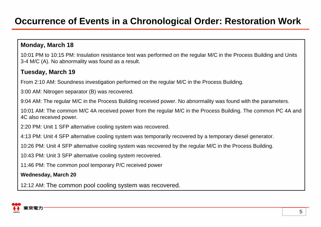
Monday, March 1810:01 PM to 10:15 PM: Insulation resistance test was performed on the regular M/C in the Process Building and Units 3-4 M/C (A). No abnormality was found as a result.
Tuesday, March 19From 2:10 AM: Soundness investigation performed on the regular M/C in the Process Building.
3:00 AM: Nitrogen separator (B) was recovered.
9:04 AM: The regular M/C in the Process Building received power. No abnormality was found with the parameters.
10:01 AM: The common M/C 4A received power from the regular M/C in the Process Building. The common PC 4A and 4C also received power.
2:20 PM: Unit 1 SFP alternative cooling system was recovered.
4:13 PM: Unit 4 SFP alternative cooling system was temporarily recovered by a temporary diesel generator.
10:26 PM: Unit 4 SFP alternative cooling system was recovered by the regular M/C in the Process Building.
10:43 PM: Unit 3 SFP alternative cooling system recovered.
11:46 PM: The common pool temporary P/C received power
Wednesday, March 20
12:12 AM: The common pool cooling system was recovered.
Occurrence of Events in a Chronological Order: Restoration Work

6
Okuma line 3L, 4L Yonomori line 1L, 2L
3A 3A
5B
4A 10A
6A
4A
5B
5A
⑫Tr
⑩Tr
5A
Location where the incident
occurred
Power Supply System Structure at the Time of the Incident
Radioactive accumulated water recovery/treatment
facility, KURION
⑥Tr
Unit 4 SFP alternative cooling system
(Secondary system)
⑪Tr
Common pool cooling
Nitrogen separator (B)*2
Unit 1 SFP alternative cooling system (regular)
⑨Tr
Unit 3 gas control system
(A) *1, 2
*1 Suspended*2 No functional problem found
Common M/C (1B)
Common M/C (1A)
Common M/C (2A)
Common M/C (2B)
Backup M/C at the substation
Backup M/C in the Process Building
Regular M/C in the Process Building
Common D/G (A) M/C
Common D/G (A)
Common M/C (4B)
Common M/C (4A)
Common M/C (3A)
Common M/C (3B)
Water treatment
facility M/C B
Main Anti-earthquake
Building M/C B
Units 3-4 temporary M/C (A)
Common D/G (B) M/C
Common D/G (B)
Evaporative concentration
treatment facility M/C
Process Building P/C CCommon
P/C 4CCommon
P/C 4A
Receiving power from A system
Receiving power from B system
Power supply suspended
Lines not yet receiving power
Trip CB
Circuit breaker
Critical load systems suspended due to the incident
Unit 4 SFP alternative cooling system
(Primary and secondary systems)
Unit 4 SFP alternative
cooling system (Primary system)

7
[Power supply system structure]Since power receiving cable renovation for the regular M/C in the Process Building (as part of Tsunami countermeasures) was ongoing at the time of the incident, the regular M/C was temporarily receiving power from the backup M/C in the Process Building.[Analysis]1. The ground relay in B system operated: The failure is assumed to have occurred in B system and high voltage power supply system.2. The circuit breakers of the regular M/C (3A) and (4A) in the Process Building and the backup M/C in the Process Building (3A) tripped due to overcurrent.: The failure is assumed to have occurred in the downstream of the regular M/C in the Process Building (4A).3. The ground directional relays and the circuit breakers of Units 3-4 temporary M/C (4A), (5A) and (10A) did not operate.: The failure is assumed to have occurred in the upstream of the load systems of Units 3-4 temporary M/C.4. Fault current was found in Units 3-4 temporary M/C (A) (5B).: The failure is assumed to have occurred in the downstream of Units 3-4 temporary M/C (A) (5B).
(4A) (10A)
(5B)
(3A) (3A) (4A) (4B)
(1B) (1B)
Circuit breaker operated due to overcurrent
Okuma line 3L
*
(6A)
Ground overvoltage
relay confirmed
Vo=6.45kV
The failure is assumed to have occurred in Units 3-4 temporary M/C (A).
Fault current confirmed
(5A)Protection relays and circuit breakers did not operate
66kV switchyard in the south side
(5A)
Opened automatically during power supply suspension in order to prevent unnecessary cutting of circuit breakers due to magnetizing inrush currentupon restart
4
Okuma line 4L
Legend
Receiving power
SuspendedSuspended due to tripping
Common M/C (2B)
Common M/C (2A)
Backup M/C at the substation
Backup M/C in the Process Building
Regular M/C in the Process Building
Units 3-4 temporary M/C (2A)
*Common M/C (4A)
Transformer No.10
Transformer No.11
Transformer No.12
Transformer No.6-1
Transformer No.6-2
Common pool temporary P/C
Circuit breaker operated due to overcurrent
Circuit breaker operated due to overcurrent
1
2
3
Circuit breaker operated due to undervoltage
Ground overvoltage
relay confirmed
Vo=6.45kV
Ground overvoltage
relay confirmed
Vo=6.75kV
Identification of the Location of Failure
8
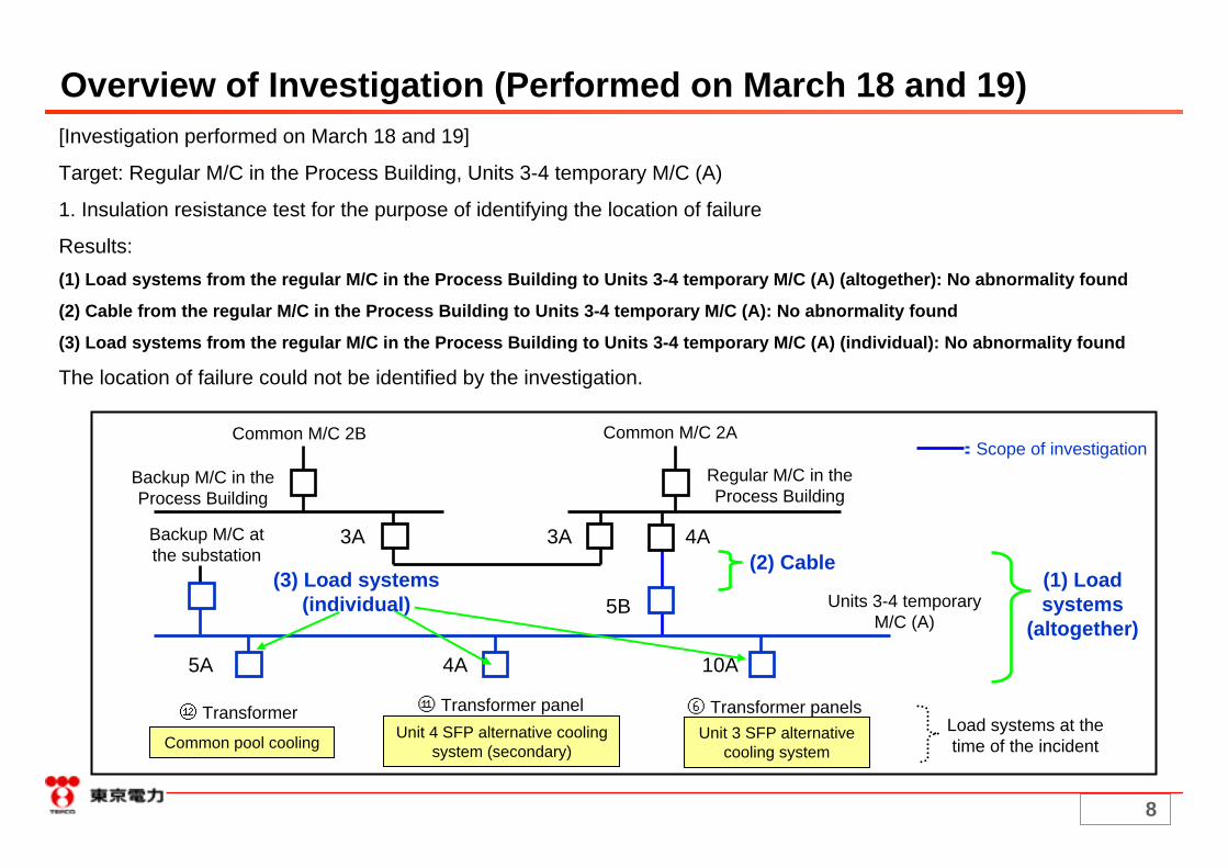
Overview of Investigation (Performed on March 18 and 19)[Investigation performed on March 18 and 19]
Target: Regular M/C in the Process Building, Units 3-4 temporary M/C (A)
1. Insulation resistance test for the purpose of identifying the location of failure
Results:(1) Load systems from the regular M/C in the Process Building to Units 3-4 temporary M/C (A) (altogether): No abnormality found
(2) Cable from the regular M/C in the Process Building to Units 3-4 temporary M/C (A): No abnormality found
(3) Load systems from the regular M/C in the Process Building to Units 3-4 temporary M/C (A) (individual): No abnormality found
The location of failure could not be identified by the investigation.
Common M/C 2B
3A 3A 4A
5B
5A 4A 10A
(1) Load systems
(altogether)
Common M/C 2A
Regular M/C in the Process Building
Backup M/C in the Process Building
Units 3-4 temporary M/C (A)
Backup M/C at the substation
Load systems at the time of the incident
(3) Load systems (individual)
(2) Cable
:Scope of investigation
⑫ Transformer
Common pool cooling Unit 4 SFP alternative cooling system (secondary)
⑪ Transformer panel ⑥ Transformer panelsUnit 3 SFP alternative
cooling system

9
3A 3A 4A
5B
5A 4A 10A
1
Location of failure
Overview of Investigation (Performed on March 20)[Investigation performed on March 20]
Target: Units 3-4 temporary M/C (A)
1. Appearance inspection of Units 3-4 temporary M/C (A)Results: Traces of a short circuit and an arc were found in Unit 5A of Units 3-4 temporary M/C (A) (Investigation results (1), (2) and (3)). A mouse was found dead on the floor of the same unit (Investigation results (1) and (4)).
2. Appearance inspection of circuit breakers, insulation resistance testResults: Discoloration was found on the circuit breakers (Investigation result (5)).
3. Appearance inspection of power receiving cable, insulation resistance test, conduction resistance testResults: No abnormality was found.
Common M/C 2B Common M/C 2A:Scope of investigation
Regular M/C in the Process Building
Backup M/C in the Process Building
Backup M/C at the substation
Units 3-4 temporary M/C (A)
2
3
Load systems at the time of the incident
⑫ Transformer
Common pool cooling Unit 4 SFP alternative cooling system (secondary)
⑪ Transformer panel ⑥ Transformer panelsUnit 3 SFP alternative
cooling system
10
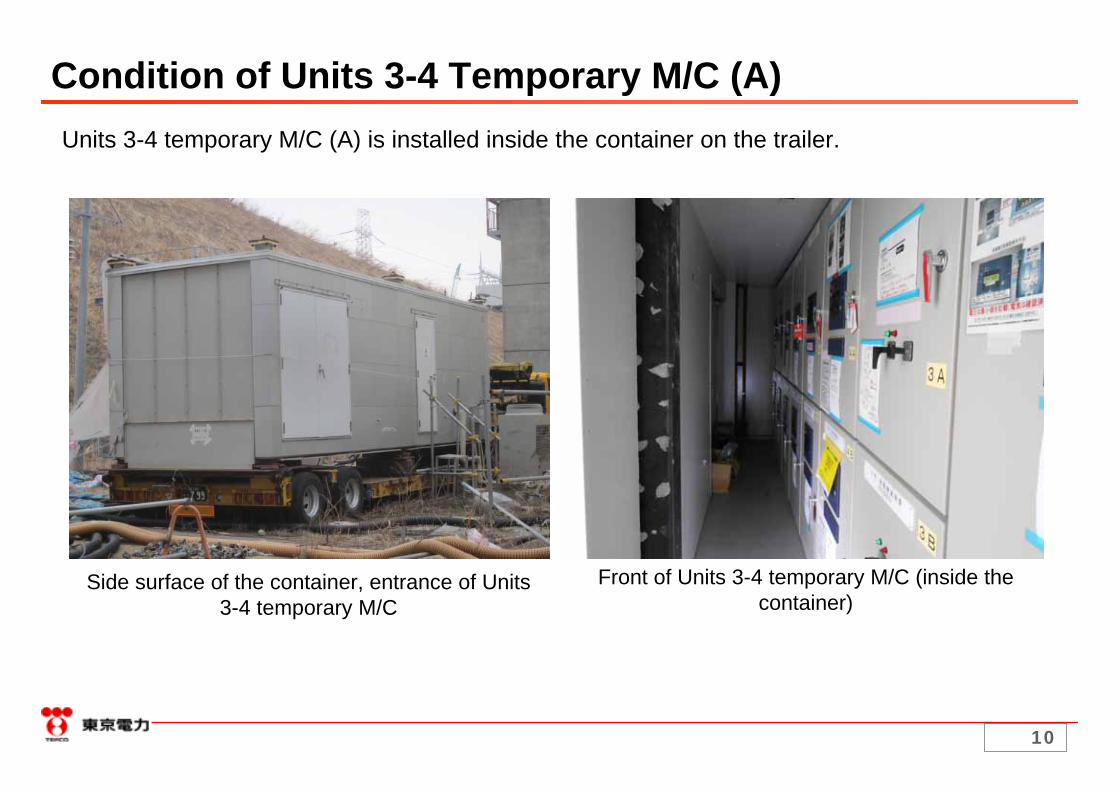
Condition of Units 3-4 Temporary M/C (A)Units 3-4 temporary M/C (A) is installed inside the container on the trailer.
Side surface of the container, entrance of Units 3-4 temporary M/C
Front of Units 3-4 temporary M/C (inside the container)
11
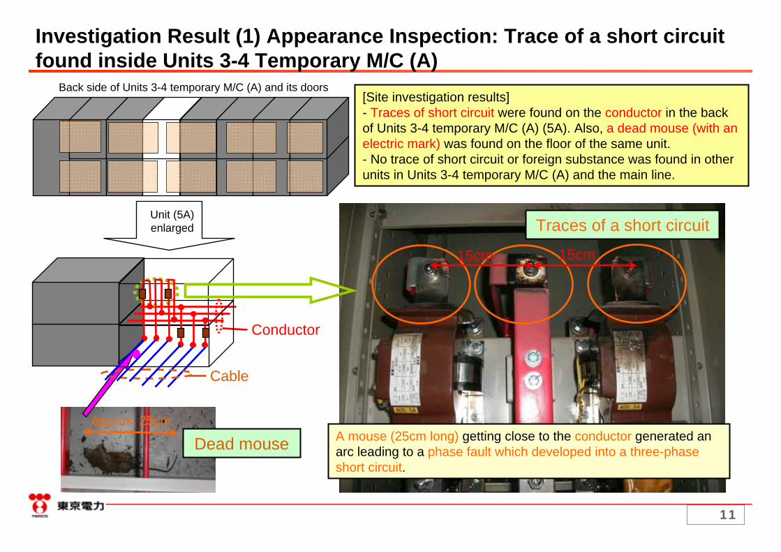
Back side of Units 3-4 temporary M/C (A) and its doors
Investigation Result (1) Appearance Inspection: Trace of a short circuit found inside Units 3-4 Temporary M/C (A)
Dead mouseApprox. 25cm
Cable
Conductor
Unit (5A) enlarged Traces of a short circuit
15cm 15cm
A mouse (25cm long) getting close to the conductor generated an arc leading to a phase fault which developed into a three-phase short circuit.
[Site investigation results]- Traces of short circuit were found on the conductor in the backof Units 3-4 temporary M/C (A) (5A). Also, a dead mouse (with an electric mark) was found on the floor of the same unit.- No trace of short circuit or foreign substance was found in otherunits in Units 3-4 temporary M/C (A) and the main line.

12
Sound condition of power panel (6A)Inside the power panel (5A) after short circuit occurred
Investigation Result (2) Condition of Units 3-4 Temporary M/C (A) Compared to Sound ConditionRegular inspectionVisual inspection (check for abnormalities, strange sound/smell from the outside of the power panel) is performed once a week during patrol. No problem was found at a visual inspection performed in the morning of March 18, 2013.Results of inspection of the inside of the power panels after the power supply facilities failureNo problem was found with units other than 5A where short circuit occurred.
Traces of short circuit
Soot
Photo 1: Inside the power panel after short circuit occurred Photo 2: Sound condition of power panel

13
Investigation Result (3) Traces of Arc Found in Units 3-4 Temporary M/C (A)
Traces of arc were found near the terminal of unit 5A.
Trace of an arc found on the top surface of unit 5A
Traces of short circuit found near the terminal of unit 5A
Trace of an arc found on the side surface of unit 5A
Trace of an arc
(Legend)
Side surface
Terminal
Top surface

14
Investigation Result (4) Appearance Inspection: Dead Mouse Found in Units 3-4 Temporary M/C (A)
A dead mouse (Photo 1) was found on the floor of Units 3-4 temporary M/C (A) unit 5A. An electric mark (Photo 2) was found on its body.
Mark from electric shock
Photo 1: Dead mouse found in units 5A and 5BPhoto 2: Enlarged image of the electric mark

15
Investigation Result (5) Appearance Inspection of Circuit Breakers, Insulation Resistance Test Results: Discoloration of Units 5A/5B Circuit Breakers of Units 3-4 Temporary M/C (A)
Unit 5A
Discoloration
As a result of appearance inspection of circuit breakers and insulation resistance test, discoloration was found in the lowerpart of the vacuum valves in units 5A and 5B circuit breakers which is considered to be due to the fault current.
5A circuit breaker5A circuit breaker
Vacuum valveVacuum valve
Unit 5B
Discoloration
Vacuum valveVacuum valve
5B circuit breaker5B circuit breaker
Side view (Transparent view)

16
Assumed Route by which the Mouse Entered Units 3-4 Temporary M/C (A)Container where Units 3-4 temporary
M/C (A) is installedLocation where cable is drawn in
Sheet removed for inspection
The cable penetration area is closed with a sheet.
With the sheet removed, the exposed current-carrying area can be accessed.
- A mouse may have gotten into the unit from the opening generated by sheet partially coming off.- Since the sheet was removed for investigation, trace of mouse, etc. could not be confirmed.- No abnormality was found with the appearance of the sheet, etc. at the time of inspection performed in the morning of March 18.

17
Mouse Feces Found in Units 3-4 Temporary M/C (A)Inspection opening
of the containerUnits 3-4 temporary M/C (A)
Dead mouse
Side view (Transparent view) Substances which are assumed to be feces were found on the floor of units 5A and 5B.
Substances which are assumed to be mouse feces were found on the floor of Units 3-4 temporary M/C (A) unit 5A and 5B.

18
The power system of system B became unstable and the voltage decreased.
Units 3-4 M/C (A) and the regular M/C in the Process Building were suspended as their circuits were cut.
Flow of Events Resulting in the Power Supply Failure
The relays detected the overcurrent and the circuit breakers operated to cut the fault current*.(*Since the same overcurrent value was set for the relays, they operated simultaneously
and the circuit breakers at three locations operated at the same time.)
Unit 3 SFP, Unit 4 SFP, the common pool cooling system, etc. were suspended.
Unit 1 SFP (secondary system) and the nitrogen separator (B) were suspended due to the impact of potential changes.
A mouse got into Units 3-4 temporary M/C (A)
An arc generated due to the mouse getting close to the current-carrying area resulted in a phase faultwhich developed into a three-phase short-circuit. Overcurrent was generated in the system.
19
Okuma line 3L, 4L
⑫Tr
⑥Tr
⑪Tr
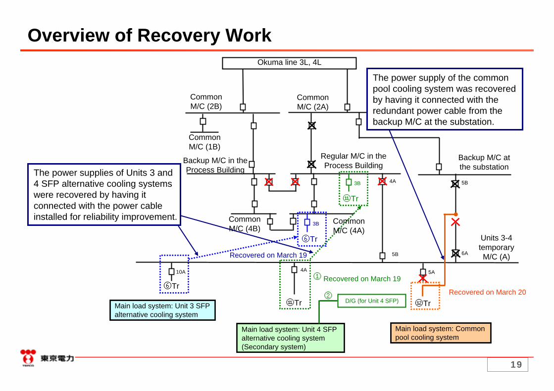
Main load system: Unit 4 SFP alternative cooling system (Secondary system)
Main load system: Common pool cooling system
Main load system: Unit 3 SFP alternative cooling system
10A 4A 5A
3B
⑥Tr
5B
Recovered on March 20
Recovered on March 19
Recovered on March 19
4A
6A5B
①
②D/G (for Unit 4 SFP)
3B
⑪Tr
Overview of Recovery Work
Common M/C (2B)
Common M/C (2A)
Common M/C (1B)
Backup M/C at the substation
Backup M/C in the Process Building
Regular M/C in the Process Building
Common M/C (4B)
Common M/C (4A)
Units 3-4 temporary M/C (A)
The power supply of the common pool cooling system was recovered by having it connected with the redundant power cable from the backup M/C at the substation.
The power supplies of Units 3 and 4 SFP alternative cooling systems were recovered by having it connected with the power cable installed for reliability improvement.

20
Reasons Why Power Supply Recovery Required a Substantial Amount of Time
1. Cause investigation was performed safely and carefully considering that the identification of cause is a basic process of recurrence prevention.2. Since the insulation resistance value was normal, identifying the cause required a substantial amount of time.3. Considering the pool water temperature increase is gradual and it takes four days or more for it to reach the maximum allowed limit stipulated by the technical specification (65℃), safer and more effective recovery measures were considered.4. Investigation and recovery required a large amount of time due to the following environmental factors as well.- Since there were multiple affected facilities at different locations, workers needed to move from one place to another for investigation and recovery work.- Investigation required the use of a flash light as the lights were off.- As there were some facilities affected outside of the area where PHS could be used, workers had to move to a location to get in touch with the Main Anti-earthquake Building.- Since the affected facilities are located in a high radiation area, there were restrictions in terms of the radiation exposure dose and the amount of time workers are allowed to engage in work (workers needed to be switched).
0.226℃/h
0.368℃/h
0.146℃/h
0.076℃/h
Spent fuel pool water temperature increase rate
(as of March 18)
176 hours (7.34 days)25.2℃Common pool
108.7 hours (4.52 days)25℃Unit 4
351 hours (14.6 days)13.7℃Unit 3
645 hours (26.86 days)16℃Unit 1
Time to reach 65℃Spent fuel pool temperature
before cooling was suspended (as of 4:00 PM on March 18)

21
Recurrence Prevention MeasuresReliability Improvement MeasuresPower supply reliability improvement measures have been implemented for the spent fuel pool cooling systems which were suspended due to the power supply failure.
■Units 1-4 SFP alternative cooling systems
- For Units 1-2 SFP alternative cooling systems, a switchboard has been installed and the power supply has been duplicated.
- The load systems previously receiving power from Units 3-4 temporary M/C (A) will be connected to the permanent common M/C4A and the regular M/C in the Process Building. Furthermore, the cable of Units 3-4 SFP alternative cooling systems will be made redundant to allow for connection with common M/C4B and the backup M/C in the Process Building in the case of M/C failure.
Work completed on March 26, 2013Work completed on March 26, 2013
- Measure to reduce time for switching power supply by utilizing the cable of Units 3-4 SFP alternative cooling systems will be considered.
■Common pool cooling system
The common pool cooling system will be duplicated by newly installing the common pool M/C (A) and (B).
Work to be completed at the end of September 2013, however,Work to be completed at the end of September 2013, however, work implementation ahead of schedule is being work implementation ahead of schedule is being considered.considered.
Measures for protecting the power panels from small animalsIn addition to the countermeasures for small animals currently being implemented, the openings such as cable penetration areas will be closed for high voltage power panels which can be significantly affected by power supply failure.

22
⑪Tr⑥Tr
⑨Tr③Tr
Reliability Improvement (SFP Alternative Cooling Systems)66kV switchyard in the south side
Common transformer B
Common transformer A
Common D/G M/C (A)
Common D/G (A)
Common D/G M/C (B)
Common D/G (B)
Common M/C 2A
Common M/C 2B
Common M/C 1A
Common M/C 1B
Backup M/C at the substation
Power supply car750kVA
Power supply car500kVA
Backup M/C in the Process
Building
Evaporative concentration
treatment facility M/C Common
M/C 4B
Common M/C 3B
Common M/C 3A
Common M/C 4A
Regular M/C in the Process
Building
Units 3-4 temporary M/C load system switching
Units 3-4 temporary
M/C (A)
Switched
Unit 3 SFP alternative
cooling system
Unit 1 covering
Unit 4 SFP alternative
cooling system (Secondary
system)
Cable redundancy allows for power supply switching Common
pool temporary
P/C
Switchboard
Newly installed
Power supply duplication for Units 1-2 SFP
N2 supply equipment (PSA4)
Unit 1 alternative IA compressor
Unit 2 SFPalternative
cooling system
Unit 1 SFPalternative
cooling system
23
Backup M/C at the substation
⑫Tr
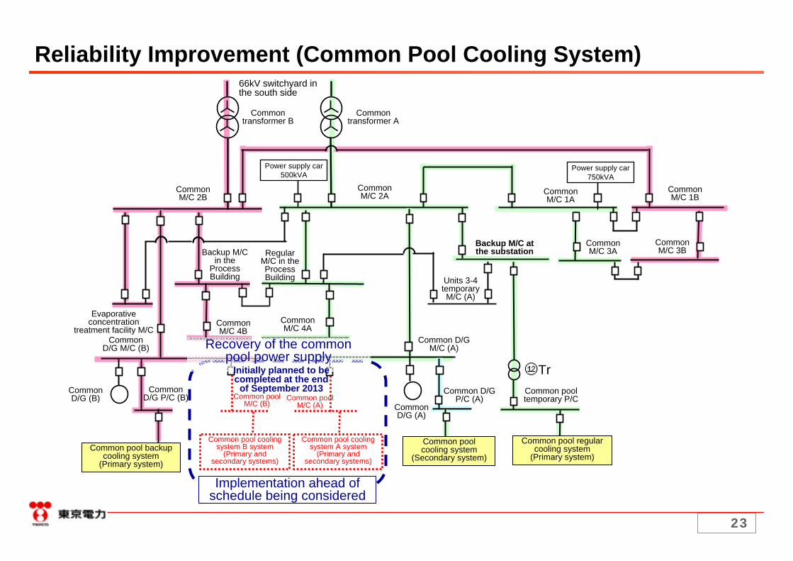
Common pool cooling system
(Secondary system)
Common pool M/C (B)
Common pool cooling system B system
(Primary and secondary systems)
Implementation ahead of schedule being considered
Recovery of the common pool power supply
Reliability Improvement (Common Pool Cooling System)66kV switchyard in the south side
Common transformer A
Common transformer B
Power supply car750kVA
Power supply car500kVA
Common M/C 2B
Common M/C 2A Common
M/C 1ACommon M/C 1B
Common M/C 3B
Common M/C 3A
Units 3-4 temporary M/C (A)
Common pool temporary P/C
Common D/G M/C (A)
Common D/G P/C (A)
Common D/G (A)
Common D/G (B)
Common D/G P/C (B)
Common D/G M/C (B)
Common M/C 4ACommon
M/C 4B
Regular M/C in the Process Building
Backup M/C in the
Process Building
Evaporative concentration
treatment facility M/C
Common pool regular cooling system
(Primary system)Common pool backup
cooling system (Primary system)
Common pool M/C (A)
Common pool cooling system A system
(Primary and secondary systems)
Initially planned to be completed at the end
of September 2013

24
Measures for protecting the power panels from small animals
Cable penetration area has been closedand mousetraps have been installed.
Building where M/C is installed
Permanent M/C has been installed inside the building after being sealed to prevent easy access to the current-carrying area.
After investigating the openings of the permanent M/C, additional countermeasures for small animals will be discussed.
Permanent M/C
25
Part 2: Investigation of Cause of Delayed Report and Announcement and the Countermeasures

26
Timeline of Events and Reports/Announcements Related to the Power Facilities Failure
Monday, March 186:57 PM: Part of the power supply facilities in the power station were suspended (the regular M/C in the Process Building and the common M/C4A)7:13 PM: Power failure occurred, M/C mainline suspended, soundness of Units 1-3 reactor water injection systems confirmed, KURION suspended, No
problem found with the MP (reported from the power station).7:20 PM: Instruction given to perform site investigation of facilities (including the facilities which cannot be monitored by monitoring systems (Web camera,
etc.).7:37 PM: Report given to the concerned parties in accordance with Article 25 of the Act on Special Measures concerning Nuclear Emergency
Preparedness (Part of the power supply facilities being suspended, no problem found with the reactor water injection systems and the MPs).7:41 PM to 8:02 PM: The suspension of Units 1, 3 and 4 SFP alternative cooling systems confirmed at the site (as for Unit 1, only the seconday system
was suspended). The flow rate of the common pool cooling system confirmed to be 0m3/h.8:10 PM: The suspension of Units 3-4 temporary M/C (A) confirmed (the condition of the monitoring room was confirmed by the recovery team). 8:27 PM: The suspension of Units 1, 3 and 4 SFP alternative cooling systems and the flow rate of the common pool cooling system (0m3/h) were reported
from the power station.8:55 PM: The restart of Unit 2 SFP alternative cooling system (at 6:38 PM) was reported from the power station (restart after a planned suspension for
recovery work).8:57 PM: Report given to the concerned parties in accordance with Article 25 of the Act on Special Measures concerning Nuclear Emergency
Preparedness (Recovery of Unit 2 SFP alternative cooling system).9:10 PM: Unit 1 SFP alternative cooling system (primary system) suspended manually.9:38 PM: Report given to the concerned parties in accordance with Article 25 of the Act on Special Measures concerning Nuclear Emergency
Preparedness (Suspension of Units 1, 3 and 4 SFP alternative cooling systems).10:08 PM: Mail sent to from TEPCO to the Press (public announcement).10:25 PM: Report given to the concerned parties in accordance with Article 25 of the Act on Special Measures concerning Nuclear Emergency
Preparedness (Suspension of Units 3-4 temporary M/C (A), no problem found with Units 5-6).11:10 PM: The common pool cooling system judged to be suspended.11:16 PM: Report given to the concerned parties in accordance with Article 25 of the Act on Special Measures concerning Nuclear Emergency
Preparedness (Suspension of the common pool cooling system and nitrogen supply equipment (nitrogen separator B), etc.).Tuesday, March 194:08 AM: Report given to the concerned parties in accordance with Article 25 of the Act on Special Measures concerning Nuclear Emergency
Preparedness (Restart of the nitrogen supply equipment (nitrogen separator B)).8:05 AM: Mail sent to from TEPCO to the Press (public announcement).From 10:00 AM: Press conference (10:00 AM at Fukushima, 10:20 AM at the Head Office)

27
Public announcements in the case of insufficient information available will be considered.
The information we had at the time was not sufficient for making public announcements.
E-mail was sent to the Press to notify the statuses of facilities and inquiries were handled as they came in.
The information we initially had was insufficient for making pubic announcements.
Information which mitigates social anxiety such as the progress of recovery work and the target timing of recovery was not provided in the announcements.
Though we try our best to announce as much information as possible to mitigate social anxiety, the identification of the failure location (which is necessary for recovery work) required a substantial amount of time and thus the start of recovery work was delayed.
Only the statuses of facilities were announced.
The transmission of information which mitigates social anxiety was not sufficient in a critical situation such as SFP cooling suspension.
Announcements will be made earlier by preparing e-mail drafts beforehand and strengthened liaison with the concerned parties.
After making reports/announcements, some time was needed for creating a draft and checking with the concerned parties.
E-mail was sent to the Press after checking with the concerned parties beforehand.
The public announcement of SFP cooling suspension was made (10:08 PM) about 30 minutes after the report/announcement was given (9:38 PM).
Considering the importance of the information, a statement such as “we are investigating the possibility of…” should have been made in the report/announcement. The time target for announcing matters of high social interest was also not set or shared.
We intend to make public announcements based on accurate information (report and announcement). At that time, we had information that there was a possibility of SFP cooling being suspended which was deemed to be the most important information. However, since the information on SFP cooling being suspended was not included in the first report, we decided to wait to make a public announcement until we get accurate information (we were expecting to get the information before long).
Judgment was made to wait for a report of SFP cooling being suspended which is critical information.
When a report was given to the concerned parties at 7:37 PM after the power failure occurred (at 6:57 PM), public announcement was not made.
Our public relations system was not organized enough to put the announcements of important problems at the top priority.
We judged that the time order of events occurring was important when making reports/announcements.
The announcement of unintended SFP cooling suspension due to the power supply failure was made after other announcement (recovery of Unit 2 SFP cooling which had been intentionally suspended) was made at the TV conference (8:55 PM).
The announcement of SFP cooling suspension was given to the concerned parties (9:38 PM) about an hour and a half after the announcement was made at the TV conference (8:27 PM).
Remote monitoring functions during a power supply failure were not insufficient.
Site investigation was necessary as web camera, etc. were unavailable due to the power supply failure.
Since remote monitoring was disabled due to the power supply failure, investigation had to be performed at the site.
The announcement of SFP cooling suspension at a TV conference (8:27 PM) was made about an hour and a half after the power supply failure occurred.
Challenge/reflection pointsReason/causeHandlingIssue
Issues Related to Delayed Report/Announcement and Incident Handling

28
1. Countermeasures in the operation side In the case of an incident which causes social anxiety*, reports/announcements and public announcements will be promptly based on
the information obtained. Emergency press conferences are to be considered as necessary.*Unintended suspension of fuel cooling functions (RPV/PCV water injection systems, PCV nitrogen injection system, spent fuel pool system, PCV gas control system), wide-range power supply failure, contaminated water leakage to the outside of the power station site, etc.
Reports/announcements and public announcements on the statuses of major facilities after a failure occurs will be made even when the information is probable. For example, when there is a possibility that a certain facility is suspended (but not certain), statements including “under investigation”, etc. can be given.
Information which mitigates anxiety such as the progress status of recovery work and the target timing of recovery will be included in the reports/announcements and public announcements.
When giving public announcements regarding an incident which causes social anxiety, policies such as the target time for making a public announcement are to be shared.
In the case of an incident which causes social anxiety occurs, the concerned parties shall be gathered for swift implementation of recovery work and external correspondence.
2. Countermeasures in the facility side Reliability improvement measures (monitoring system duplication, installation of uninterruptible power supply system, etc.) will be
implemented for the remote monitoring functions to allow for checking the statuses of major facilities at the central monitoring room.
3. Providing information to the people of Fukushima in the case of an incident which causes social anxiety Announcements will be available on our home page to provide information to the people of Fukushima and broader society. The contents of public relations documents regarding incident overview and measure implementation progress will be incorporated into
our public relations magazine (issued with cooperation from the local municipalities) and other medias for the purpose of effectively providing information to the people of Fukushima.
Provide information to the local municipalities through visiting and contacting by phone in addition to providing reports/announcements.
Countermeasures for Issues Related to Delayed Report/Announcement and Incident Handling

29
Reliability Improvement of Remote Monitoring Functions
Situation at the time of power supply failure During the power supply failure occurred on March 18, the remote monitoring functions for the
nitrogen injection system and the SFP alternative cooling system were partially disabled. The remote monitoring functions for the monitoring parameters necessary for understanding
the status of the reactor water injection system (injection water amount, RPV/PCV temperatures) and the monitoring parameters necessary for subcriticality monitoring (PCV gas control system) were functioning properly during the power supply failure since reliability improvement measures (such as emergency battery installation and monitoring camera duplication) had been implemented.
Current issue Since the monitoring frequency of the nitrogen injection system, the SFP alternative cooling system
and the common pool cooling system at a normal time is comparatively high (once every 24 hours) and it was deemed that the statuses of these systems could be confirmed at the site even in the case of remote monitoring system abnormality, the implementation of reliability improvement measures such as camera duplication was judged to be unnecessary.
Reliability improvement measures Taking into consideration the above issue, the necessity of reliability improvement measures for the
remote monitoring systems for critical facilities was considered. As a result, we have determined to implement measures such as the monitoring system duplication and uninterruptible power supply installation for the nitrogen injection system, the SFP alternative cooling system and the common pool cooling system for the purpose of allowing for confirming the operational statuses of facilities from the remote central monitoring room in the case of single failure of power supply system facilities.

30
Statuses of Remote Monitoring Functions at the Time of the PowerSupply Failure on March 18
OK: Remote monitoring properly functioned during the power supply failure
Disabled: Remote monitoring was disabled during the power supply failure
No remote monitoring function availableDisabledOKNo remote monitoring
function availableSFP alternative cooling system (SFP secondary system status display)
DisabledDisabledOKOKSFP alternative cooling system (SFP primary system flow rate)
-OK (Common for Units 1-3)Nitrogen injection system (Flow rate at the outlet of the Nitrogen Separator)
-DisabledOKOKNitrogen injection system (RPV/PCV N2 injection flow rate)
OKCommon pool cooling system (FPC/FPCW status indicator lamp)
-OKOKOKPCV gas control system
-OKOKOKReactor water injection system(RPV/PCV temperatures)
-OKOKOKReactor water injection system(Injection water flow rate)
Unit 4Unit 3Unit 2Unit 1Facility

31
Statuses of Remote Monitoring Systems for Critical Facilities and the Necessity of Reliability Improvement Measures
NecessaryNoNo(SFP secondary system status display)
Necessary (though not affected by the power supply failure occurred
this time)
NoNoCommon pool cooling system(FPC/FPCW status indicator lamp)
NecessaryNoNoNitrogen injection system (Air pressure for operating Unit 1 PCV injection valve)
No
Yes (Except for Unit 1)
Yes (PC, camera)
Yes (Camera duplication)
No
Yes (Digital recorder duplication)
Yes (Camera duplication)
Multiplicity and diversity of remote monitoring functions
No
No
Power supply for the monitoring PC has been
separated.
No
No
Battery has been installed in one of the digital recorders
Power supply for the duplicated camera has been separated
Countermeasures for power supply facility failure
Common pool cooling system(FPC system discharge pressure gauge)
NecessarySFP alternative cooling system(SFP primary system flow rate)
Already implementedPCV gas control system
NecessaryNitrogen injection system (RPV/PCV N2 injection flow rate)
NecessaryNitrogen injection system (Flow rate at the outlet of the Nitrogen Separator)
Already implementedReactor water injection system(RPV/PCV temperatures)
Already implementedReactor water injection system(Injection water flow rate)
Necessity of reliability improvement measuresFacility (Monitoring parameters)

32
Part 3: Measures for Swift Recovery of Facilities for WhichStable Operation is Required

33
Implementation Progress of Measures for Swift Recovery of Critical Facilities in the Case of Power Supply Failure
Completed*3CompletedCompletedNitrogen injection system
SFP cooling facility Completed*3Not completed*4Partly completed*1
Partly completed*4
Completed
Completed
System duplication and diversification
Completed*6
Completed*3
Completed*3
Availability of spare goods and
procedure manual
CompletedReactor water injection system
Partly completed*5Common pool cooling system
CompletedPCV gas control system
Power supply multiplicationFacility
*1 Active components, etc. have been multiplied.
*2 Power can be supplied via temporary D/Gs (with limited availability). Multiplication work has been completed on March 26.
*3 Excluding part of long lead goods.
*4 Recovery work ongoing at the time of the power supply failure. Facility recovery and multiplication work have been completed on March 22.
*5 Multiplication completed for the primary system. As for the secondary system, multiplication will be implemented ahead of schedule.
*6 The procedure manuals have been prepared. Spare goods are under consideration.
34
Reliability Improvement Measures for the Spent Fuel Pool Cooling System
On August 31, 2012, we reported on reliability improvement measures implemented in accordance with a directive document “Further measures to include in the implementation plan on reliability improvement measures at Fukushima Daiichi Nuclear Power Station (Direction)” (July 25, 2012 NISA No.4, July 25, 2012).
In the report, it was stated that the SFP circulation cooling system shall be restarted in a day or so even after unintended suspension. Specifically, the following measures are to be implemented by the end of March 2013. Power supply (M/C, P/C) multiplication Enhanced maintenance to reduce risk in the case of unintended suspension Preparation of spare goods, procedure manuals, etc.
35
Implementation Progress of Reliability Improvement Measures at the Time of the Power Supply Failure Occurred This Time
The implementation progress of reliability improvement measures at the time of the power supply failure occurred this time was as follows. As for power supply multiplication, a switchboard was being installed in Units
1 and 2 to prepare for power supply duplication. At Units 3 and 4, power supply switching from temporary to permanent was ongoing.
As for enhanced maintenance, inspection was being carried out inaccordance with the long-term maintenance plan developed in October 2012.
The preparation for spare goods and procedure manuals had been almost completed except for part of the long lead goods.
36
Recovery After the Power Supply Failure and Future Action Plans
[Recovery after the power supply failure]Considering that a procedure to utilize a temporary D/G in the case of power
supply failure had been developed and the increase of pool water temperature is gradual, it was being assumed that recovery would complete within a day or so after power supply failure.Though the amount of time necessary for power supply recovery work at the
site utilizing a temporary D/G was initially estimated to be about half a day, the actual amount of time necessary for starting a temporary D/G was approx. 3.5 hours.
[Future action plans]Establish a procedure to promptly implement measures such as starting a
temporary D/G in the case of a power supply failure as well as a training plan to further reduce the time of recovery work at the site.As for Unit 4 with the largest amount of heat generation, the deployment of a
temporary D/G near the plant is being considered in order to further reduce the time to start the temporary D/G.

37
[Reference] Spent Fuel Pool Cooling System Facilities
Example: Unit 4Reactor Building
Waste treatment BuildingOutdoor
From the spent fuel pool cooling
purification systemTo the residual heat removal system
To the spent fuel pool cooling
purification system
Skimmer surge tank
Spent fuel pool
: Duplicated: Common: Existing line: Shared between the temporary and existing lines
Primary system pump (B)
Heat exchanger
(B)
Primary system pump (A)
Heat exchanger
(A)Strainer
Secondary system pump (A)
Secondary system pump (B)
Surge tank
Air fin cooler (B)
Air fin cooler (A)

38
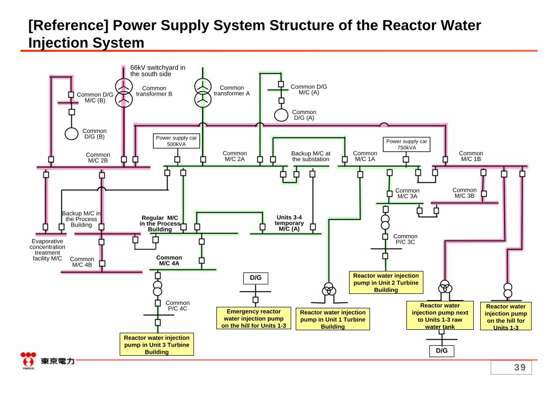
The reactor water injection system is to be diversified through installing multiple systems such as (1) reactor water injection system on the hill, (2) reactor water injection system next to the raw water tank and (3) reactor water injection system in the Turbine Building. The power supply for the three systems above is separated. Also, an emergency D/G is installed for (1) and (2) to accommodate the case where power supply is lost. Thus, the power supply system structure with the measures above incorporated allows for swift restart of reactor water injection in the case of power supply failure due to failure/degradation of power supply facilities through system switching and starting the emergency D/G.
Other mechanical, electrical and instrumentation control equipment can also be swiftly restarted through system switching and starting the emergency D/G driven pump in the case of power supply failure due to failure/degradation.
A procedure to swiftly implement measures above (system switching and starting the emergency D/G) has been created and system operation check is performed on a regular basis.
Measures for Swift Recovery of the Reactor Water Injection System
39
[Reference] Power Supply System Structure of the Reactor Water Injection System
Reactor water injection pump in Unit 3 Turbine
Building D/G
66kV switchyard in the south side
Common D/G M/C (B)
Common transformer A
Common transformer B
Common D/G M/C (A)
Common D/G (A)
Common D/G (B)
Power supply car750kVA
Common M/C 2B
Power supply car500kVA
Common M/C 2A
Common M/C 1A
Common M/C 1B
Backup M/C at the substation
Backup M/C in the Process
Building
Evaporative concentration
treatment facility M/C Common
M/C 4B
Common M/C 3B
Common M/C 3A
Common M/C 4A
Regular M/C in the Process
Building
Units 3-4 temporary
M/C (A)Common P/C 3C
Common P/C 4C Emergency reactor
water injection pump on the hill for Units 1-3
Reactor water injection pump in Unit 1 Turbine
Building
Reactor water injection pump in Unit 2 Turbine
Building
Reactor water injection pump next
to Units 1-3 raw water tank
Reactor water injection pump on the hill for
Units 1-3
D/G

40
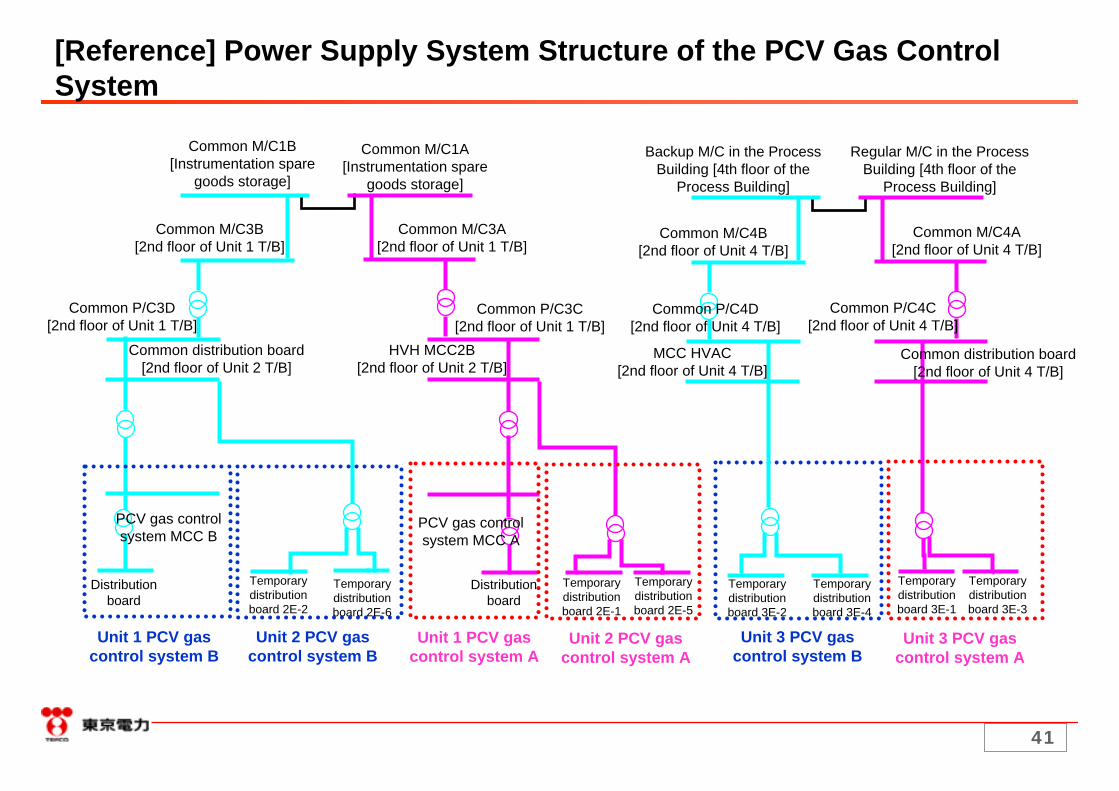
The power supply (M/C) multiplication has been implemented for the PCV gas control system and each power supply receives power from different common main power line. Thus, the power supply system structure allows for swift restart of system in the case of a power supply failure due to failure/degradation of power supply facilities through system switching, etc.
Other mechanical, electrical and instrumentation control equipment can also be swiftly restarted through switching to the standby system in the case of power supply failure due to failure/degradation.- There are two systems (A and B) for the active components of the mechanical equipment and each receives power from the power supply of different system.- As for the instrumentation equipment to measure the concentration of hydrogen, noble gas, etc., two systems are in operation at all times and thus parameter monitoring can be continued when one system fails or degrades.
A procedure to swiftly implement measures above (system switching and starting operation) has been created and system operation check is performed on a regular basis.
Measures for Swift Recovery of the PCV Gas Control System
41
Unit 1 PCV gas control system B
Unit 1 PCV gas control system A
Common M/C1B[Instrumentation spare
goods storage]
Common M/C3B[2nd floor of Unit 1 T/B]
Common distribution board [2nd floor of Unit 2 T/B]
Backup M/C in the Process Building [4th floor of the
Process Building]
[Reference] Power Supply System Structure of the PCV Gas ControlSystem
Common M/C1A[Instrumentation spare
goods storage]
Common M/C3A[2nd floor of Unit 1 T/B]
Common P/C3D[2nd floor of Unit 1 T/B]
Common P/C3C[2nd floor of Unit 1 T/B]
HVH MCC2B[2nd floor of Unit 2 T/B]
Regular M/C in the Process Building [4th floor of the
Process Building]
Common M/C4B[2nd floor of Unit 4 T/B]
Common M/C4A[2nd floor of Unit 4 T/B]
Common P/C4D[2nd floor of Unit 4 T/B]
Common P/C4C[2nd floor of Unit 4 T/B]
MCC HVAC[2nd floor of Unit 4 T/B]
Common distribution board [2nd floor of Unit 4 T/B]
PCV gas control system MCC A
PCV gas control system MCC B
Distribution board
Distribution board
Temporary distribution board 2E-2
Temporary distribution board 2E-6
Temporary distribution board 2E-1
Temporary distribution board 2E-5
Temporary distribution board 3E-2
Temporary distribution board 3E-4
Temporary distribution board 3E-1
Temporary distribution board 3E-3
Unit 2 PCV gas control system B
Unit 3 PCV gas control system B
Unit 2 PCV gas control system A
Unit 3 PCV gas control system A
42
The nitrogen injection system normally supplies nitrogen by two nitrogen separators (electromotive drive) in parallel operation. As the two nitrogen separators receive power from different power supplies, nitrogen supply can be continued even if the power supply for one of the nitrogen separators is lost. An additional nitrogen separator (electromotive drive) has been installed in mid March and will be put in operation once the implementation plan is approved.
In addition to the nitrogen separators above, emergency D/G driven nitrogen separators have been installed.
With the reliability improvement measures above, the nitrogen injection can be swiftly restarted in the case of a power supply failure due to power supply facility failure/degradation through switching to the regular system backup equipment, starting the emergency D/G, etc.
A procedure to swiftly implement measures above (system switching and starting operation) has been created and system operation check is performed on a regular basis.
Measures for Swift Recovery of the Nitrogen Injection System

43
Nitrogen separator (A)
Nitrogen separator (B)
[Reference] Power Supply System Structure of the Nitrogen Injection System
Common M/C1B Common M/C1A
Transformer panel
Transformer panel
Transformer panel
Nitrogen separator (C)*
*Additionally installed

44
The facilities of the common pool cooling system currently available for operation are; cooling purification system pumps (A, C), component cooling system pumps (A, C), air fin coolers (A1, A2, C1, C2, E1) and the system multiplication has been implemented.*Cooling purification system pump (B), component cooling system pump (B) and air fin coolers (B1,B2,E2,D1,D2,F1,F2) are to be recovered.
As the cooling purification system pumps and the component cooling system pumps receive power from different power supply systems (A and C), the system can be swiftly restarted in the case that the power supply of one system is lost through system switching.*Though the backup pump was not available on March 18 due to the ongoing recovery work, it has been recovered.
Though air fin coolers currently in operation receive power from the same power supply system, the power supply system structure allows for receiving power from an emergency D/G (prepared as a backup power supply) in the case of a power supply failure. Further reliability improvement measures such as receiving power from different power supply systems and power supply multiplication are currently being considered.
Measures for Swift Recovery of the Common Pool Cooling System

45
D/G
Okuma line 3L, 4L
Air fin coolers (A-1), (A-2), (C-1), (C-2), (E-1)
D/G
Common transformer A
[Reference] Power Supply System Structure of the Common Pool Cooling System
Common transformer B
Common M/C2A Common M/C2B
Common D/G(A)Common D/G M/C (A)
Backup M/C at the substation
Common D/G M/C (B) Common D/G(B)
Common pool temporary P/C480 Common D/G(A) P/C 480 Common D/G(B) P/C
Cooling purification system pump (A)
Component cooling system pump (A)
Cooling purification system pump (C)
Component cooling system pump (C)

46
Common Pool Building
Spent fuel pool
Outdoor
Skimmer surge tank
Component cooling system pumps
Surgetank
Check valve
Cooling purification system pumps
F/D
(A)
Air fin coolers (A1-F2)
*One system in operation
[Reference] Common Pool Cooling System (Overview)
(C) (B)
Cooling purification systemheat exchanger
(A)
(B)
(C) *One system in operation