multicode - interempresas...10 español 2.2 instalaciÓn la máquina esta ensamblada, calibrada y...
TRANSCRIPT
MULTICODE
MÁQUINA DUPLICADORAKEY CUTTING MACHINE
www.jma.es

MULTICODEMANUAL DE INSTRUCCIONES
MÁQUINA DUPLICADORA
Espa
ñol

4
Espa
ñol
SUMARIO
1.- PRESENTACIÓN Y ASPECTOS GENERALES .................................................................................51.1 GENERALIDADES .................................................................................................................................5
1.2 TRANSPORTE Y EMBALAJE ...................................................................................................51.3 ETIQUETA IDENTIFICADORA ...................................................................................................5
2.- INSTALACION Y CARACTERISTICAS DE LA MAQUINA .............................................................62.1 ELEMENTOS PRINCIPALES DE LA MAQUINA ........................................................................62.1.1 MULTICODE ..........................................................................................................................6
2.1.2 Soporte tablet y tablet. ..................................................................................................62.1.3 Alimentador y cable de alimentación ............................................................................8
2.2 INSTALACIÓN .......................................................................................................................102.3 DESCRIPCION DE LA MÁQUINA ...........................................................................................102.4 FAMILIA Y TERMINOLOGIA DE LAS LLAVES. .......................................................................112.5 DATOS TÉCNICOS .................................................................................................................122.6 CAJA DE ACCESORIOS .........................................................................................................13
3.- MORDAZAS ......................................................................................................................................143.1 MORDAZA PARA LLAVES PLANAS ......................................................................................14
3.1.1 Uso de la mordaza estándar “MP1”. ...........................................................................143.2 MORDAZA PARA LLAVES DE PUNTO Y REGATA .................................................................16
3.2.1 La mordaza. ..................................................................................................................163.2.2 Tipo de tope. ................................................................................................................173.2.3 Modelo de garras. ........................................................................................................18
3.3 AJUSTE DE DIFERENTES MORDAZAS .................................................................................193.3.1 Ajuste mordaza llaves planas. .....................................................................................193.3.2 Ajuste mordaza seguridad ...........................................................................................20
4.- USO DE LA TABLET .........................................................................................................................224.1 CARGAR Y ENCENDER LA TABLET .......................................................................................224.2 ELECCION IDIOMA ................................................................................................................22
5.- LIMPIEZA Y SEGURIDAD ...............................................................................................................246.- MANTENIMIENTO...........................................................................................................................24
6.1 ACCESO A LA PARTE TRASERA ............................................................................................256.2 SUSTITUCION CONTROL. ......................................................................................................256.3 LIMPIAR ZONA BANDEJA VIRUTA. ......................................................................................266.4 SUSTITUCION FRESA PRISMATICA ......................................................................................266.5 SUSTITUCION FRESA CILINDRICA ........................................................................................27
7.- ELIMINACION DE DESHECHOS ....................................................................................................287.1 EMBALAJE ............................................................................................................................287.2 VIRUTA ..................................................................................................................................287.3 MAQUINA .............................................................................................................................28
8.- ASISTENCIA .....................................................................................................................................289.- GUIA OPERATIVA SOFTWARE ......................................................................................................29
9.1 ENLACE BLUETOOTH ............................................................................................................309.2 CAMBIO IDIOMA ...................................................................................................................329.3 LLAVE ESCALA 1:1 ................................................................................................................329.4 BÚSQUEDAS .........................................................................................................................34
9.4.1 Búsquedas por fabricante de cerradura (Zona Estandares) ........................................349.4.2 Búsquedas de automoción, por tipo, marca, modelo y año (Zona Automoción) .........379.4.3 Búsqueda de llaves por equivalencias a otro fabricante (Zona Equivalencias) ..........38
9.5 INFORMACIÓN DE CORTE (FICHA) .......................................................................................399.5.1 Fichas llaves serreta ....................................................................................................399.5.2 Ficha llave de puntos ...................................................................................................439.5.3 Ficha llave regata/ranura .............................................................................................46
9.6 AJUSTE MORDAZAS ............................................................................................................489.6.1 Ajuste mordaza serreta ................................................................................................499.6.2 Ajuste mordaza puntos/regata ....................................................................................49
9.7 ACTUALIZAR FIRMWARE .....................................................................................................509.8 DIAGNÓSTICO .......................................................................................................................52
5
Espa
ñol
MULTICODEMÁQUINA DUPLICADORA
1.- PRESENTACIÓN Y ASPECTOS GENERALES
1.1 GENERALIDADESLa máquina duplicadora MULTICODE ha sido diseñada teniendo en cuenta las normas de seguridad vigentes en la C.E.E.
La seguridad del personal involucrado en el manejo de este tipo de máquinas solo se consigue con un programa bien diseñado en seguridad personal, como la implantación de un programa de mantenimiento y el seguimiento de los consejos recomendados así como el cumplimiento de las normas de seguridad que contempla este manual.
Aunque la instalación de la máquina no presenta ninguna dificultad, es preferible que no intente instalar, ajustar o manipular la misma sin leer primeramente este manual.
La máquina sale de nuestra fabrica lista para el uso y solo necesita operaciones de calibrado para los útiles que se van a utilizar.
1.2 TRANSPORTE Y EMBALAJE La máquina se presenta en el interior de un embalaje de las dimensiones siguientes:
Ancho = 610mm, largo = 510mm, alto = 520mm.
Peso máquina más embalaje = 27+5=32 Kg. de peso.
Cuando desembale la máquina, inspeccione cuidadosamente por si hubiese sufrido algún daño en el transporte. Si encuentra alguna anomalía, avise inmediatamente al transportista y no haga nada con la máquina hasta que el agente del transportista haya realizado la inspección correspondiente.
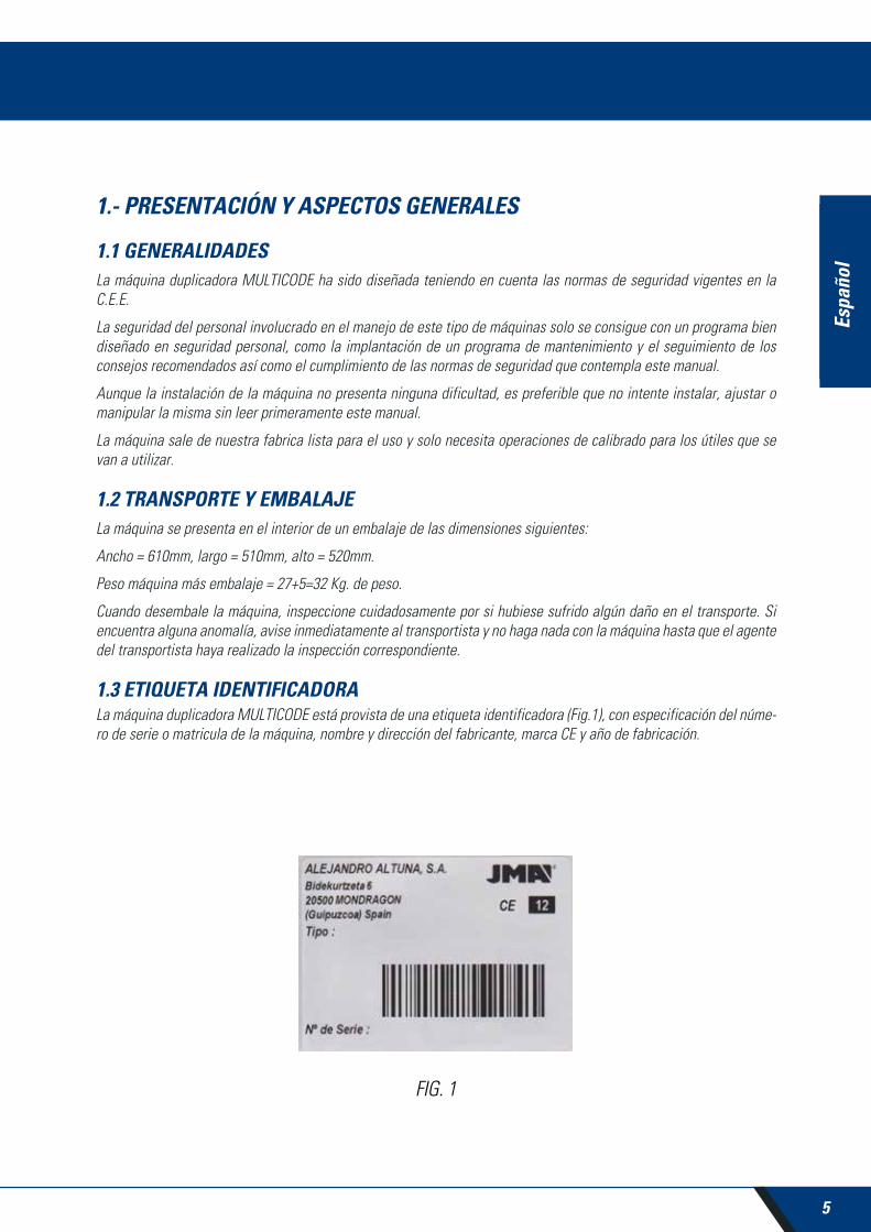
1.3 ETIQUETA IDENTIFICADORALa máquina duplicadora MULTICODE está provista de una etiqueta identificadora (Fig.1), con especificación del núme-ro de serie o matricula de la máquina, nombre y dirección del fabricante, marca CE y año de fabricación.
FIG. 1
Espa
ñol

6
Espa
ñol
4
2
7
65
1
8
9
10
3
11
12
13
14
15
16
18
19
.
17
2.- INSTALACIÓN Y CARACTERÍSTICAS DE LA MÁQUINA
2.1 ELEMENTOS PRINCIPALES DE LA MÁQUINA2.1.1 MULTICODE
FIG. 2
2.1.2 SOPORTE TABLET Y TABLET
En la caja de la máquina, embalados separadamente, están los siguientes componentes:
• Soporte tablet y tablet.
Estos dos componentes se deben instalar en la máquina de la siguiente manera (Fig.2):
1. Tablet2. Soporte tablet3. Pomos tablet4. Guarda trasera5. Enchufe alimentación6. Seta emergencia7. Bandeja viruta8. Luz led9. Display10. Soporte herramientas11. Fresa serreta12. Mordaza MP1
13. Guarda eje Z14. Carro Z15. Mordaza llave puntos16. Carro XY17. Guarda transparente18. Conector USB Tipo B19. Conector USB Tipo A (Carga tablet)

7
Espa
ñol
MULTICODEMÁQUINA DUPLICADORA
1. Desenroscar los pomos (T1) ubicados en la maquina. (Fig.3)
2. Instalar el soporte tablet.
3. Enroscar y apretar el pomo para fijar el soporte tablet en la parte superior de la máquina.
4. Introducir la tablet en el soporte.
• Uso y regulación del soporte tablet
El soporte tablet tiene diferentes regulaciones:
1. Regulación altura de garra superior. Girando la palanca (A) en sentido horario, se puede regular la altura de la garra (B) para introducir la tablet. Una vez ajustado, bloquear, girando en sentido antihorario. Las garras (C) y (D) se regulan para adecuar al tamaño de la tablet.
FIG. 4
FIG. 3
T1
AB
C D

8
Espa
ñol
2. Regulación en altura del apoyo de la tablet (E). Girar en sentido antihorario el pomo (F), mover en altura las garras de la tablet. Una vez ajustado, bloquear el pomo (F), girando en sentido horario.
3. Giro del apoyo de la tablet (E). Desenclavando el enganche (F), se consigue girar el soporte donde se apoya la tablet. Una vez posicionado, volver a bloquear.
FIG. 5
FIG. 6
2.1.3 ALIMENTADOR Y CLAVE DE ALIMENTACIÓN
FIG. 7
+
X X1

9
Espa
ñol
MULTICODEMÁQUINA DUPLICADORA
Conectar la MULTICODE con el alimentador (X) y conectar este último a la toma de corriente por medio del cable de alimentación (X1).
Nota: Conectar el conector de 4 pines de 24V DC con la cara plana mirando hacia abajo.
FIG. 8
FIG. 9

10
Espa
ñol
2.2 INSTALACIÓNLa máquina esta ensamblada, calibrada y controlada; lista para el uso y no necesita operaciones de montaje. En todo caso, antes de la primera puesta en marcha, es oportuno efectuar los controles siguientes:
• Conectar la máquina MULTICODE a la tensión de alimentación adecuada (220V 50Hz o 110V 50/60 Hz) a través del alimentador suministrado(Ver apart 2.1.3)
• Muy importante que la instalación eléctrica del establecimiento tenga conexión a tierra. Asegurarse que la máquina está conectada a tierra.
Después de haber desembalado la máquina y conectado el cable suministrado a la toma de corriente, la máquina esta preparada para su uso.
Asegurarse de que la seta de emergencia no esté pulsada, en caso contrario desenclavar la seta.
Una vez puesto en marcha, los carros se moverán a su posición de inicio (en el caso que no lo estuviesen) y en el display se iluminará una luz verde. (Fig.10)
La máquina MULTICODE, funciona solamente si esta conectada a la TABLET con el programa JMAKeyPro. La comu-nicación entre el software y la máquina es mediante Bluetooth.
Dicho esto, encender la tablet y luego activar el software. Una vez activado el programa, en el display se iluminará una luz azul. (Fig.10). La máquina esta preparada para trabajar.
2.3 DESCRIPCIÓN DE LA MÁQUINALa máquina MULTICODE ha sido diseñada para cortar llaves tipo planas y de puntos/regata. En la fase de diseño se ha analizado hasta los más mínimos detalles para fabricar una máquina compacta, fácil de utilizar y que sea precisa. Es una máquina mecatrónica, con tres motores paso a paso para el desplazamiento de los carros.
En definitiva, estamos ante una máquina versátil, que se puede utilizar tanto para llaves planas, de punto o regata.
Lee y/o decodifica las llaves planas con cifrado estándar y llaves de punto/regata utilizando un palpador con contacto eléctrico.
FIG. 10
MARCHA

11
Espa
ñol
MULTICODEMÁQUINA DUPLICADORA
2.4 FAMILIA Y TERMINOLOGÍA DE LAS LLAVESLa máquina MULTICODE duplica los siguientes tipos de llaves:
• Llaves planas(A) y vehículos (B).
• Llaves de punto (D), regata / ranura (vehículos) (E).
FIG. 11
1.Cabeza2.Tope3.Dentado
4.Paletón5.Dorso6.Punta

12
Espa
ñol
2.5 DATOS TÉCNICOSLos principales datos técnicos se reflejan a continuación:
Alimentación eléctrica 24V d.c-7,5 Amp.-180W
Alimentador: 100/240V a.c- 50/60HZ-180W
Fresa. Prismática (Llaves planas) De acero rápido. Velocidad de giro 1100rpm.
Fresa. Cilíndrica (Llaves de puntos/regata) De metal duro. Velocidad de giro 12000rpm.
Mordaza estándar (MP1) para llaves planas De cuatro lados.
Mordaza para llaves puntos/regata Con garras intercambiables
Desplazamiento Con husillo de bolas accionadas por motores paso a paso sobre guías de rodillos rectificados.
Cursos útiles X= 45mm.. Y= 45mm.
Z= 30mm.
Alumbrado Diodo Led.
Dimensiones Profundidad: 413mm
Ancho: 427mm
Alto con soporte+tablet: 612mm
Alto sin soporte +tablet: 431mm
Tablet Model: Lenovo TB2-X30F
Masa 27Kg.

13
Espa
ñol
MULTICODEMÁQUINA DUPLICADORA
2.6 CAJA DE ACCESORIOSLa máquina MULTICODE viene equipada con una caja de accesorios para el mantenimiento y reglaje (Fig.12).
Los accesorios son los siguientes:
FIG. 12
Llave fija 18 mm
Varilla bloqueo fresaØ4x30
Pincel
Tope punta
Fresa 01F
Fresa 2F
Llave Allen 2mm
Llave Allen 2.5mm
Llave Allen en ‘T’ 3 mm
Llave Allen 4mm
Palpador reglajemordaza RP
Llave Allen 5mm
Fusible: T6.3A 250V
Plantilla reglaje CRG
Fresa 03F
Garras C y D
Chapa de ajuste RPC

14
Espa
ñol
FIG. 13
3.- MORDAZAS
La máquina consta de dos mordazas, una para mecanizar llaves planas y otra para llaves de puntos y/o regata. A continuación se detalla el uso de las dos mordazas para un correcto funcionamiento.
3.1 MORDAZA PARA LLAVES PLANAS
3.1.1 USO DE LA MORDAZA ESTÁNDAR “MP1”
La mordaza estándar “MP1” esta diseñada para la lectura y mecanizado de las llaves planas. A la hora de amarrar la llave, hay que tener en cuenta dos aspectos: Lado y tope de la llave.
• Lado 1, 2, 3 y 4 de la mordaza estándar “MP1”.
A continuación, se indican los diferentes lados y características de la llave a amarrar:
a) El duplicado de la llave con apoyo en el dorso:
Lado 1: llaves con paletón normal.
Lado 2: llaves con paletón estrecho.
b) El duplicado de la llave mediante el amarre de la llave por el perfil:
Lado 3: Llave con guía en la parte inferior.
Lado 4: Llave con guía en la parte superior.
Representación de la mordaza estándar con imágenes de diferentes amarres (Fig.13)
La mordaza estándar consta de 4 lados (numeración grabada en la parte superior de la mordaza) que permiten cerrar las llaves amarradas en el dorso y perfil. La mordaza esta diseñada para sujetar distintos modelos de llaves. La operación de cambio de lado es sencillo, dejar la mordaza un poco abierta y girar manualmente hasta el lado deseado.

15
Espa
ñol
MULTICODEMÁQUINA DUPLICADORA
• Tope de la llave.
Una vez elegido el lado de la mordaza, falta posicionar la llave longitudinalmente, para ello hay que tener en cuenta el tope de la llave. Dependiendo del modelo de llave, hay dos tipos de tope:
1. Tope cuello(C): Es el más común. El tope de la llave se realiza mediante tope mecánico de la mordaza. (Fig.14)
2. Tope punta (1, 2, 3): El tope de la llave se realiza mediante el tope punta suministrado en la caja de accesorios y se coloca junto a la llave en la ranura de la mordaza estándar.
Ejemplo de una llave colocada en el lado 1 y tope 2 (Fig.15)
FIG. 14
FIG. 15
Tope punta

16
Espa
ñol
Imagen de una mordaza con la numeración de las ranuras para realizar los topes. (Fig.16)
A la hora de introducir el código de llave a codificar o mecanizar, le aparecerá toda la información del amarre de la llave en el software JMAKeyPro de la tablet.
FIG. 16
FIG. 17
3.2 MORDAZA PARA LLAVES DE PUNTO Y REGATASegún la llave a mecanizar o codificar, seguir las indicaciones que aparecen en el software JMAKeyPro en la tablet. Las principales indicaciones se refieren a lo siguiente:
3.2.1 LA MORDAZA
Se especifica que modelo de mordaza tiene que utilizar.
En la mordaza se pueden introducir tanto llaves de punto como regata. En el caso que se tenga que sacar la mordaza, seguir los siguientes pasos:
1) Levantar el guarda transparente.
2) Aflojar el tornillo (T2) y sacar la mordaza extrayéndola hacia el operario.
3) Introducir la mordaza (limpiar la zona de alojamiento anteriormente) en la cola de milano y llevarla hasta el tope.
4) Bloquear la mordaza girando el tornillo (T2).
T2
Lado1 : Topes 1,2,3Lado 2 : Topes 1,2Lado 3 : Topes 1,2Lado 4 : Topes 1,2
17
Espa
ñol
MULTICODEMÁQUINA DUPLICADORA
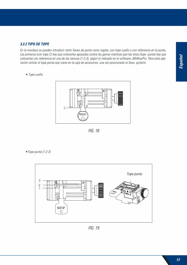
3.2.2 TIPO DE TOPE
En la mordaza se pueden introducir tanto llaves de punto como regata, con tope cuello o con referencia en la punta. Las primeras (con tope C) hay que colocarlas apoyadas contra las garras mientras que las otras (tope punta) hay que colocarlas con referencia en una de las ranuras (1-2-3), según lo indicado en el software JMAKeyPro. Para esta ope-ración utilizar el tope punta que viene en la caja de accesorios, una vez posicionado la llave, quitarlo.
• Tope cuello
•Tope punta (1-2-3)
FIG. 18
FIG. 19
Tope punta
18
Espa
ñol
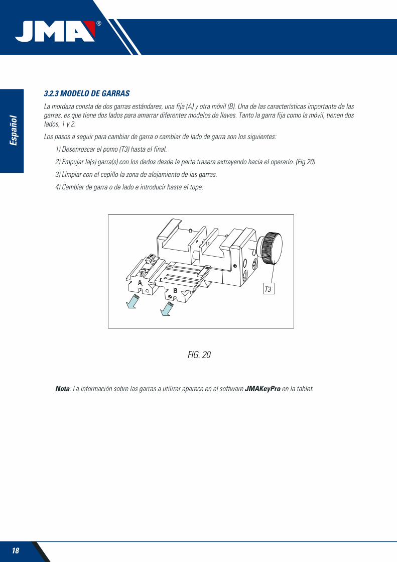
3.2.3 MODELO DE GARRAS
La mordaza consta de dos garras estándares, una fija (A) y otra móvil (B). Una de las características importante de las garras, es que tiene dos lados para amarrar diferentes modelos de llaves. Tanto la garra fija como la móvil, tienen dos lados, 1 y 2.
Los pasos a seguir para cambiar de garra o cambiar de lado de garra son los siguientes:
1) Desenroscar el pomo (T3) hasta el final.
2) Empujar la(s) garra(s) con los dedos desde la parte trasera extrayendo hacia el operario. (Fig.20)
3) Limpiar con el cepillo la zona de alojamiento de las garras.
4) Cambiar de garra o de lado e introducir hasta el tope.
Nota: La información sobre las garras a utilizar aparece en el software JMAKeyPro en la tablet.
FIG. 20
T3
19
Espa
ñol
MULTICODEMÁQUINA DUPLICADORA
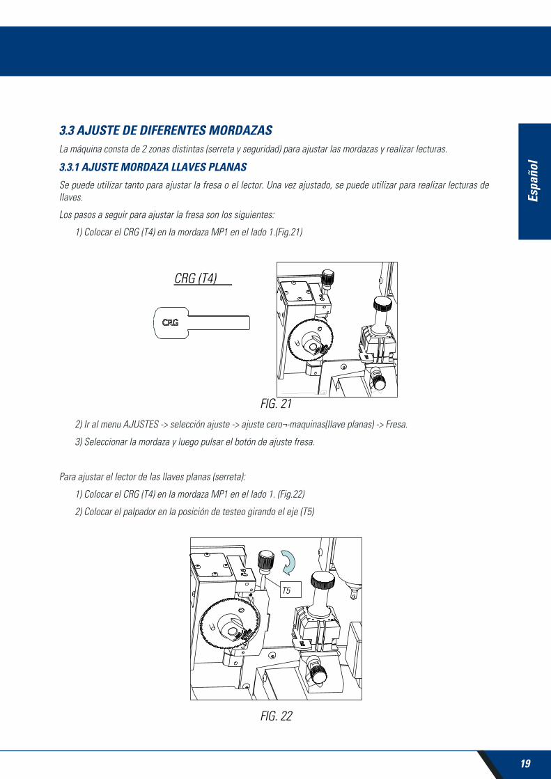
3.3 AJUSTE DE DIFERENTES MORDAZASLa máquina consta de 2 zonas distintas (serreta y seguridad) para ajustar las mordazas y realizar lecturas.
3.3.1 AJUSTE MORDAZA LLAVES PLANAS
Se puede utilizar tanto para ajustar la fresa o el lector. Una vez ajustado, se puede utilizar para realizar lecturas de llaves.
Los pasos a seguir para ajustar la fresa son los siguientes:
1) Colocar el CRG (T4) en la mordaza MP1 en el lado 1.(Fig.21)
2) Ir al menu AJUSTES -> selección ajuste -> ajuste cero¬-maquinas(llave planas) -> Fresa.
3) Seleccionar la mordaza y luego pulsar el botón de ajuste fresa.
Para ajustar el lector de las llaves planas (serreta):
1) Colocar el CRG (T4) en la mordaza MP1 en el lado 1. (Fig.22)
2) Colocar el palpador en la posición de testeo girando el eje (T5)
FIG. 21
FIG. 22

20
Espa
ñol
3) Ir al menu AJUSTES -> selección ajuste-> ajuste cero¬-maquinas(llave planas)-> Lector.
4) Seleccionar la mordaza y pulsar el botón de ajuste lector.
Para hacer lecturas de llaves planas (serreta):
1. Colocar la llave plana en el lado que corresponda de la mordaza MP1.
2. Colocar el palpador en la posición de testeo girando el eje (T5).
3. En la ficha técnica de la llave pulsar el botón de lectura de llave.
3.3.2 AJUSTE MORDAZA SEGURIDAD
3.3.2.1 PALPADOR RP
El palpador RP se utiliza para ajustar la fresa, se debe utilizar cuando se cambia de mordaza o de garras. Estos son los pasos a seguir:
1) Colocar el palpador RP en el soporte fresa (T6).
2) Fijar el palpador girando la llave allen de 3mm (T7).
3) Colocar la chapa de ajuste RPC en la mordaza, por la parte posterior de la mordaza (Fig. 24).
4) Ir al menu AJUSTES -> selección ajuste -> ajuste cero-maquinas (llaves seguridad) -> Fresa.
5) Seleccionar la mordaza y pulsar el botón de ajuste fresa.
FIG. 23
FIG. 24
T6T7

21
Espa
ñol
MULTICODEMÁQUINA DUPLICADORA
3.3.2.1 PALPADOR 1P
El palpador 1P se utiliza para ajustar el lector como para codificar las llaves de punto o regata.
Para ajustar el lector:
1) Sacar la palanca (T8) y dejarla bajar hasta su posición.
2) Colocar la chapa de ajuste RPC en la mordaza, por la parte posterior de la mordaza (Fig.25).
3) Ir al menu AJUSTES -> selección ajuste -> ajuste cero-maquinas (llaves seguridad) -> Lector.
4) Seleccionar la mordaza y pulsar el botón de ajuste fresa.
5) Una vez realizado el ciclo, volver a subir el palpador a su posición de reposo.
Para codificar las llaves de punto o regata:
1) Sacar la palanca (T8) y dejarla bajar hasta su posición.
2) En la ficha técnica de la llave pulsar el botón de lectura de llave.
FIG. 26
FIG. 25
T8T8

22
Espa
ñol
4.- USO DE LA TABLETEn la caja de la máquina, embalados separadamente, están la tablet, el cable USB/micro USB y enchufe de alimen-tación.
4.1 CARGAR Y ENCENDER LA TABLETAntes de usar la tablet, puede ser necesario cargar la batería. Dos formas de carga:
1) Conectando la fuente de alimentación (B1) de la tablet a una red 220V.
2) Conectando cable USB/microUSB (B1.1) a la propia máquina.(VER 2.1.1)
La primera vez que se conecta la tablet, es conveniente efectuar la carga total.
Encender la tablet, para ello mantener presionando durante algunos segundos el botón correspondiente (B2).
4.2 ELECCIÓN IDIOMA1) Seleccionar “Ajustes”.
FIG. 27

23
Espa
ñol
MULTICODEMÁQUINA DUPLICADORA
2) Seleccionar “Idioma e introducción de texto”.
3) Seleccionar “Idioma”.
4) Desplazar y seleccionar el idioma deseado.

24
Espa
ñol
5) Para salir, pulsar el círculo.
Nota: Todas las funciones de la MULTICODE, seguir lo que esta indicado en el software JMAKeyPro y en el manual.
Para todas otras indicaciones, seguir lo indicado en la guía rápida de la tablet.
5.- LIMPIEZA Y SEGURIDADPara la limpieza, le recomendamos que siga las siguientes pautas:
• Mantenga lo mas limpio posible las partes funcionales de la maquina, quitar con pincel las virutas de mecanizado.
• No usar en absoluto aire comprimido para limpiar la zona de trabajo de virutas, entrarían en las piezas funcionales.
Para su seguridad, le recomendamos que siga las siguientes pautas:
• No intente arrancar o manipular la máquina hasta que todos los temas de seguridad, instrucciones para la instalación, guía del operario y procedimientos de mantenimiento, hayan sido cumplimentados y entendidos.
• Desconecte siempre el suministro eléctrico, antes de realizar cualquier trabajo de limpieza o mantenimiento.
• Trabajar con las manos secas.
• Asegúrese de que la máquina tenga toma a tierra.
6.- MANTENIMIENTOAntes de emprender cualquier tipo de operación de mantenimiento, es necesario cumplir los siguientes requisitos:
• Nunca se debe efectuar ninguna operación con la máquina en marcha.
• Se debe desconectar el cable de la conexión eléctrica.
• Se han de seguir estrictamente las indicaciones del manual.
• Utilizar piezas originales de repuesto.
La máquina no necesita ningún mantenimiento en especial, únicamente revisar y en su caso, sustituir piezas que tengan desgaste; por ejemplo: fresas, mordazas, palpadores…
Nota: Para el mantenimiento preventivo de la maquina, se aconseja utilizar productos lubricantes. Evitar que el pro-ducto haga contacto con las partes electrónicas.

25
Espa
ñol
MULTICODEMÁQUINA DUPLICADORA
6.1 ACCESO A LA PARTE TRASERAPara tener acceso a la parte trasera, hay que actuar de la siguiente manera:
1) Apagar la máquina mediante la seta de emergencia y desconectar el cable de alimentación.
2) Quitar la Tablet del soporte.
3) Soltar 7 tornillos (T10) con una llave allen de 3.(Fig.28)
NOTA: No tocar los tornillos zincados
4) Quitar el guarda trasero (T11) levantando hacia arriba.
6.2 SUSTITUCIÓN CONTROLPara sustituir el control, actuar de la siguiente manera:
1) Quitar el guarda trasero. (Ver 6.1)
2) Quitar los cables que van conectados al control.
3) Soltar los dos tornillos (T12) con una llave allen de 5. (Fig.29)
4) Sustituir el control.
5) Volver a montar todos los componentes de nuevo
FIG. 28
FIG. 29
26
Espa
ñol
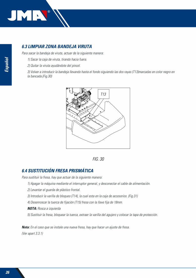
6.3 LIMPIAR ZONA BANDEJA VIRUTAPara sacar la bandeja de viruta, actuar de la siguiente manera:
1) Sacar la caja de viruta, tirando hacia fuera.
2) Quitar la viruta ayudándote del pincel.
3) Volver a introducir la bandeja llevando hasta el fondo siguiendo las dos rayas (T13)marcadas en color negro en la bancada.(Fig.30)
6.4 SUSTITUCIÓN FRESA PRISMÁTICAPara sustituir la fresa, hay que actuar de la siguiente manera:
1) Apagar la máquina mediante el interruptor general, y desconectar el cable de alimentación.
2) Levantar el guarda de plástico frontal.
3) Introducir la varilla de bloqueo (T14), la cual esta en la caja de accesorios. (Fig.31)
4) Desenroscar la tuerca de fijación (T15) fresa con la llave fija de 18mm.
NOTA: Rosca a izquierda
5) Sustituir la fresa, bloquear la tuerca, extraer la varilla del agujero y colocar la tapa de protección.
Nota: En el caso que se instale una nueva fresa, hay que hacer un ajuste de fresa.
(Ver apart 3.3.1)
FIG. 30

27
Espa
ñol
MULTICODEMÁQUINA DUPLICADORA
6.5 SUSTITUCIÓN FRESA CILÍNDRICA1) Apagar la máquina mediante el interruptor general, y desconectar el cable de alimentación.
2) Levantar el guarda de plástico frontal.
3) Desenroscar el prisionero (T16) con una llave de 3mm (T17) y sacar la fresa cilíndrica (T18). Fig.32
4) Sustituir la fresa, empujando arriba hasta el tope.
5) Roscar el prisionero. (T16)
FIG. 31
FIG. 32

28
Espa
ñol
7.- ELIMINACIÓN DE DESHECHOSPor desecho se entiende cualquier sustancia u objeto procedente de actividades humanas o de ciclos naturales, aban-donada o destinada a ser abandonada.
7.1 EMBALAJE• Como el embalaje en el que suministra la máquina MULTICODE es de cartón, el mismo se podría reciclar como embalaje.
• Como desecho, se equipara a los desechos sólidos urbanos y por lo tanto no se puede tirar más que en los contenedores especiales de cartón.
• Los cascos que protegen la maquina dentro de la caja de cartón, son de material polimérico equiparable a los desechos sólidos urbanos y por lo tanto, no se pueden eliminar más que en las instalaciones normales de elimi-nación de desechos.
7.2 VIRUTA• Los residuos procedentes de la duplicación de llaves, están clasificados como desechos especiales, pero se equiparan a los desechos sólidos urbanos, como por ejemplo un estropajo metálico.
• Estos desechos se eliminaran según como los clasifiquen las leyes vigentes en la UE, entregándolos en las instalaciones especiales de eliminación de desechos.
7.3 MÁQUINA• Antes de efectuar la demolición de la maquina e preciso ponerla fuera de servicio, cortando el suministro de energía eléctrica y separando las piezas de plástico de las piezas metálicas.
• Tras efectuar esta operación se podrán eliminar todos los desechos, en conformidad con las leyes en vigor en el país donde se utiliza la máquina.
8.- ASISTENCIAAlejandro Altuna consta de un servicio técnico para todos los clientes de la máquina MULTICODE.
Para asegurar total seguridad al operador y la máquina, cualquier trabajo no especificado en este manual, se debe realizar solamente por el fabricante o servicio técnico. Ante cualquier duda sobre el manejo de la maquina consultar en la dirección especificada en la parte posterior del manual.

29
Espa
ñol
MULTICODEMÁQUINA DUPLICADORA
9.- GUÍA OPERATIVA SOFTWAREEl software “JMAKeyPro” se utliza para el control total de la máquina multicode. Para acceder a este software solo hay que pulsar sobre el icono.la bancada.(Fig.30)
Una vez ejecutado el programa tenemos el siguiente menú principal.
1) El programa está dividido en 3 zonas diferentes según el tipo de búsqueda que se quiere realizar.
a) Búsqueda por fabricantes de cerradura
b) Búsquedas de automoción, por tipo, marca, modelo y año
c) Búsqueda de llaves por equivalencias a otro fabricante
2) Favoritos. Aquí podremos encontrar las series de llaves de uso común que hayamos mandado a favoritos.
3) Ajustes
El programa siempre nos muestra la imagen (I) de la llave en bruto, información del fabricante de cerradura (C), refe-rencias (R) de llaves en bruto de un fabricante de llaves, información adicional como referencias de equivalencias (E) de otros fabricantes de llaves y por ultimo tenemos información relativa a las series (S) asignadas a ese fabricante o modelo de llave, según se realice la consulta.
30
Espa
ñol
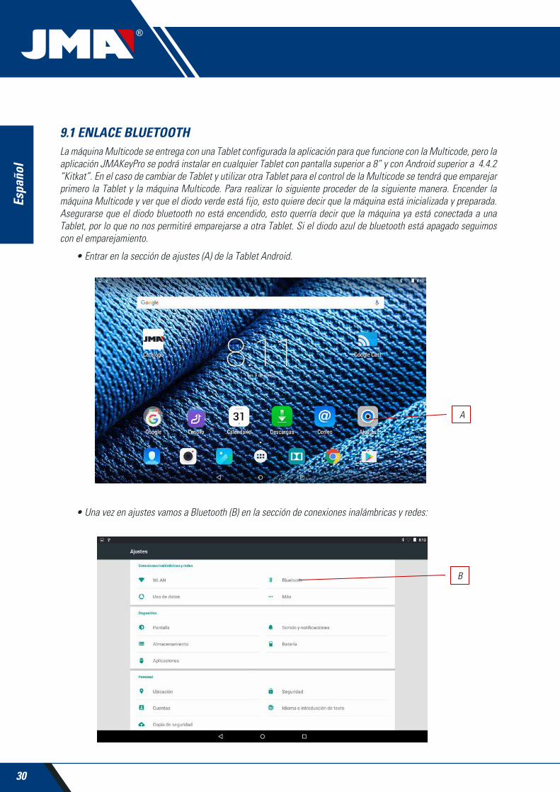
9.1 ENLACE BLUETOOTHLa máquina Multicode se entrega con una Tablet configurada la aplicación para que funcione con la Multicode, pero la aplicación JMAKeyPro se podrá instalar en cualquier Tablet con pantalla superior a 8” y con Android superior a 4.4.2 “Kitkat”. En el caso de cambiar de Tablet y utilizar otra Tablet para el control de la Multicode se tendrá que emparejar primero la Tablet y la máquina Multicode. Para realizar lo siguiente proceder de la siguiente manera. Encender la máquina Multicode y ver que el diodo verde está fijo, esto quiere decir que la máquina está inicializada y preparada. Asegurarse que el diodo bluetooth no está encendido, esto querría decir que la máquina ya está conectada a una Tablet, por lo que no nos permitiré emparejarse a otra Tablet. Si el diodo azul de bluetooth está apagado seguimos con el emparejamiento.
• Entrar en la sección de ajustes (A) de la Tablet Android.
• Una vez en ajustes vamos a Bluetooth (B) en la sección de conexiones inalámbricas y redes:

31
Espa
ñol
MULTICODEMÁQUINA DUPLICADORA
En la siguiente pantalla de dispositivos bluetooth, nos aseguramos que el bluetooth de la Tablet esté activado, para que podamos buscar todo los dispositivos que estén a nuestro alrededor (El radio de alcance son 15 metros, sin ningún tipo de obstáculos, si hubiera obstáculos como paredes esté radio de alcance suele bajar). Buscaremos el dispositivo bluetooth con nombre “JMA Multicode”.
Una vez elegido el dispositivo nos aparecerá en pantalla el mensaje de “Vinculando dispositivo”, el proceso es auto-mático, no es necesario introducir ningún código o password de emparejamiento. Una vez terminado el proceso de emparejamiento “JMA Multicode” debería de aparecer en “Dispositivos Sincronizados”.
Una vez tengamos “JMA Multicode” en dispositivos sincronizados, podemos entrar a la aplicación “JMAKeyPro” y una vez entremos a la aplicación a los pocos segundos, el diodo azul de conexión de la máquina se encenderá para indicar que la comunicación programa y Multicode está restablecida.
32
Espa
ñol
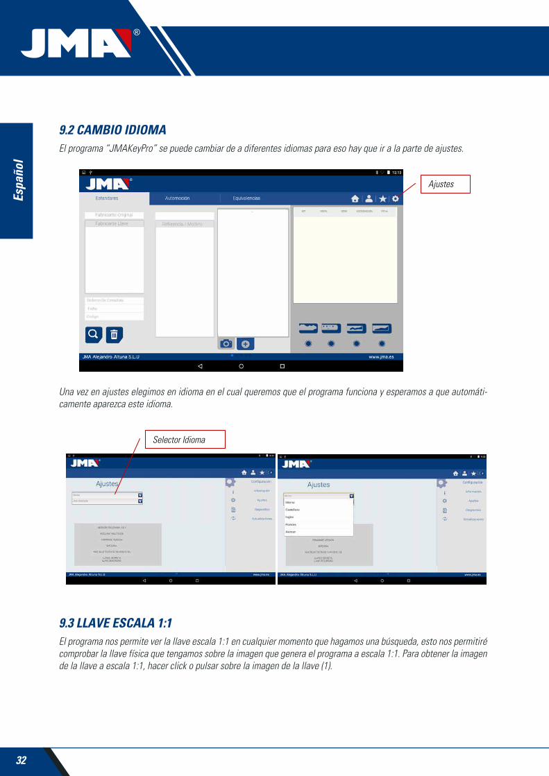
9.2 CAMBIO IDIOMAEl programa “JMAKeyPro” se puede cambiar de a diferentes idiomas para eso hay que ir a la parte de ajustes.
Una vez en ajustes elegimos en idioma en el cual queremos que el programa funciona y esperamos a que automáti-camente aparezca este idioma.
9.3 LLAVE ESCALA 1:1El programa nos permite ver la llave escala 1:1 en cualquier momento que hagamos una búsqueda, esto nos permitiré comprobar la llave física que tengamos sobre la imagen que genera el programa a escala 1:1. Para obtener la imagen de la llave a escala 1:1, hacer click o pulsar sobre la imagen de la llave (1).

33
Espa
ñol
MULTICODEMÁQUINA DUPLICADORA
Una vez pulsado sobre la imagen nos parece una ventana sobre la pantalla en la cual se muestra la llave en escala 1:1. Esta ventana tiene la peculiaridad de que toda la pantalla es insensible a los toques de la mano o de la llave, por lo que nos permite posicionar la llave física encima de la imagen en escala 1:1. La única zona sensible a la pulsación es el botón Cancelar (C) que nos permite volver al menú principal de búsqueda.
NOTA: Recordar que la imagen del menú principal no es escala 1:1 y depende del tamaño de la pantalla de la Tablet, mientras que una vez pulsada sobre la imagen siempre obtendremos una imagen escala 1:1
34
Espa
ñol
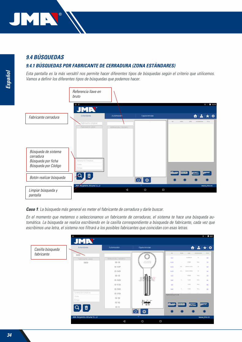
9.4 BÚSQUEDAS9.4.1 BÚSQUEDAS POR FABRICANTE DE CERRADURA (ZONA ESTÁNDARES)
Esta pantalla es la más versátil nos permite hacer diferentes tipos de búsquedas según el criterio que utilicemos. Vamos a definir los diferentes tipos de búsquedas que podemos hacer.
Caso 1: La búsqueda más general es meter el fabricante de cerradura y darle buscar.
En el momento que metemos o seleccionamos un fabricante de cerraduras, el sistema te hace una búsqueda au-tomática. La búsqueda se realiza escribiendo en la casilla correspondiente a búsqueda de fabricante, cada vez que escribimos una letra, el sistema nos filtrará a los posibles fabricantes que coincidan con esas letras.
35
Espa
ñol
MULTICODEMÁQUINA DUPLICADORA
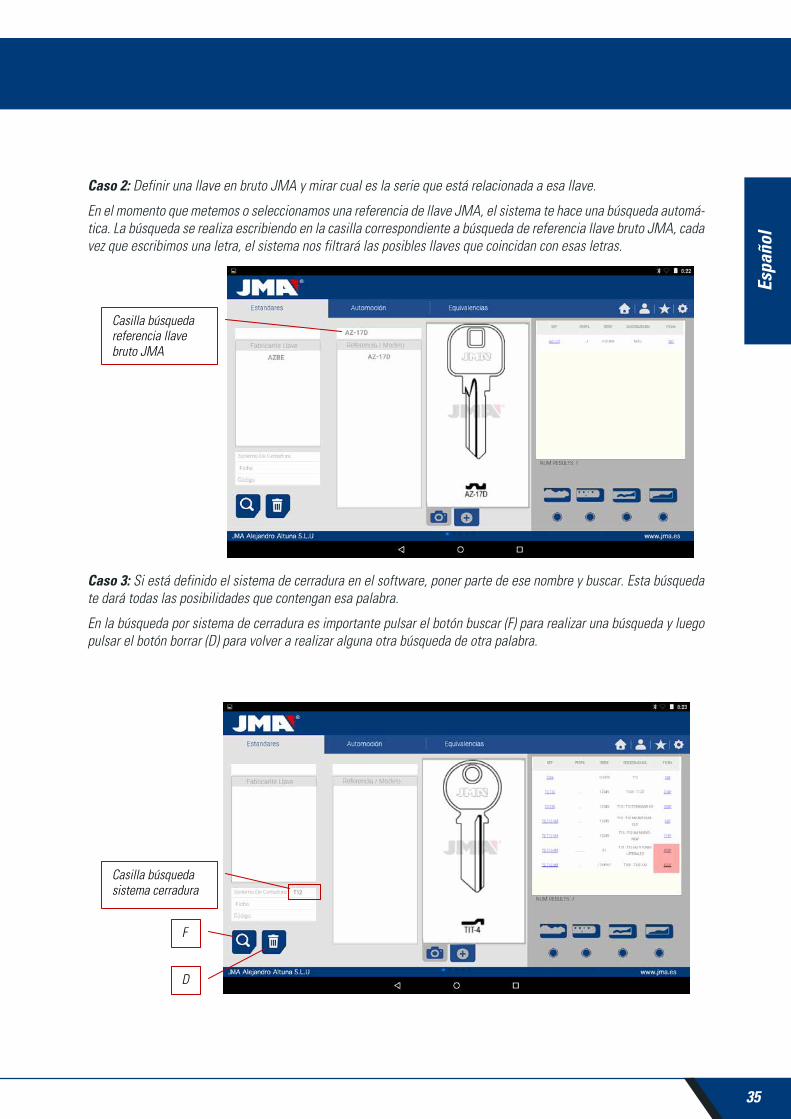
Caso 2: Definir una llave en bruto JMA y mirar cual es la serie que está relacionada a esa llave.
En el momento que metemos o seleccionamos una referencia de llave JMA, el sistema te hace una búsqueda automá-tica. La búsqueda se realiza escribiendo en la casilla correspondiente a búsqueda de referencia llave bruto JMA, cada vez que escribimos una letra, el sistema nos filtrará las posibles llaves que coincidan con esas letras.
Caso 3: Si está definido el sistema de cerradura en el software, poner parte de ese nombre y buscar. Esta búsqueda te dará todas las posibilidades que contengan esa palabra.
En la búsqueda por sistema de cerradura es importante pulsar el botón buscar (F) para realizar una búsqueda y luego pulsar el botón borrar (D) para volver a realizar alguna otra búsqueda de otra palabra.
36
Espa
ñol
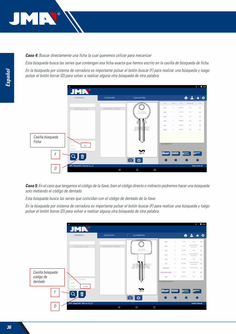
Caso 4: Buscar directamente una ficha la cual queremos utilizar para mecanizar
Esta búsqueda busca las series que contengan esa ficha exacta que hemos escrito en la casilla de búsqueda de ficha.
En la búsqueda por sistema de cerradura es importante pulsar el botón buscar (F) para realizar una búsqueda y luego pulsar el botón borrar (D) para volver a realizar alguna otra búsqueda de otra palabra.
Caso 5: En el caso que tengamos el código de la llave, bien el código directo o indirecto podremos hacer una búsqueda solo metiendo el código de dentado.
Esta búsqueda busca las series que coincidan con el código de dentado de la llave.
En la búsqueda por sistema de cerradura es importante pulsar el botón buscar (F) para realizar una búsqueda y luego pulsar el botón borrar (D) para volver a realizar alguna otra búsqueda de otra palabra.

37
Espa
ñol
MULTICODEMÁQUINA DUPLICADORA
Código indirecto: No hay relación directa con el dentado.
p.e. llave OP-D ficha 227 código D1200 -> dentado 3344443123
Los puntos (.) en series D.... 0001-2000 significan los dígitos de la serie de la llave
Código directo: Hay relación directa con el dentado.
p.e. llave TE-8I ficha 476 código 12345A -> dentado 12345
Los puntos (.) en series .....A 1234567890 significan los dientes de la llave.
9.4.2 BÚSQUEDA DE AUTOMOCIÓN POR TIPO, MARCA, MODELO Y AÑO (ZONA AUTOMOCIÓN)
Está búsqueda nos permite saber el modelo de llave JMA que utiliza un modelo de vehículo de automoción (Automó-vil, Camión o Moto), en muchos casos el cliente puede venir con la llave original del coche y como identificar el perfil puede ser una ardua tarea, podemos mirar sencillamente que modelo de llave JMA es compatible con ese modelo de automóvil para el año de construcción de ese vehículo.
Para eso será suficiente que vaya definiendo los diferentes campos de la búsqueda y pulsar la tecla de buscar (F) para realizar la búsqueda y el botón (D) limpiar/borrar para realizar una nueva búsqueda. En este caso tenemos dos casillas de resultados. La casilla de información de la llave (I) que lleva el modelo del vehículo seleccionado, dando información también del sistema transponder que lleva.
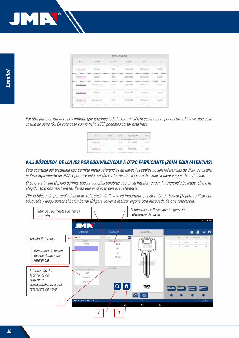
En el ejemplo siguiente podemos ver como el modelo de coche FOCUS ® de la marca FORD ®, en los años entre 2005-2010 lleva una llave parecida a la llave JMA TPX2FO-24P, el cual incorpora el transponder TPX2 y espadín perfil FO-24P, que es clonable sobre una llave original, el cual lleva un chip Texas ® Crypto.
38
Espa
ñol
Por otra parte el software nos informa que tenemos toda la información necesaria para poder cortar la llave, que es la casilla de serie (S). En este caso con la ficha 255P podemos cortar esta llave.
9.4.3 BÚSQUEDA DE LLAVES POR EQUIVALENCIAS A OTRO FABRICANTE (ZONA EQUIVALENCIAS)
Este apartado del programa nos permite meter referencias de llaves las cuales no son referencias de JMA y nos dirá la llave equivalente de JMA y por otro lado nos dará información si se puede hacer la llave o no en la multicode.
El selector incluir (P), nos permite buscar aquellas palabras que en su interior tengan la referencia buscada, sino está elegido, solo nos mostrará las llaves que empiecen con esa referencia.
ZEn la búsqueda por equivalencia de referencia de llaves, es importante pulsar el botón buscar (F) para realizar una búsqueda y luego pulsar el botón borrar (D) para volver a realizar alguna otra búsqueda de otra referencia.

39
Espa
ñol
MULTICODEMÁQUINA DUPLICADORA
9.5 INFORMACIÓN DE CORTE (FICHA)Una vez el programa esté conectado a la Multicode en el programa “JMAKeyPro” tendremos acceso a ver la informa-ción técnica de corte de la llave. Si no existe enlace con la máquina multicode está información no es accesible. Las fichas las podemos diferenciar en dos familias, según la zona de amarre y la herramienta de corte que vayan a utilizar, por eso vamos a nombrar las siguientes divisiones:
a) Fichas llaves serreta. Llaves cortadas con la herramienta horizontal y donde tenemos la mordaza MP1 de cuatro lados, posibilidad de cambiar a otras mordazas, personalizadas a perfiles especiales de llaves.
b) Fichas llaves de punto o regata. Llaves cortadas con herramienta vertical, la mordaza de esta zona tiene garras intercambiables según el modelo de llave, el software nos indicará la garra necesaria en cada instante. Será necesario reglar la máquina cada vez que se haga un cambio de garras.
9.5.1 FICHAS LLAVES SERRETA
Al realizar la búsqueda de una llave (AZBE) o un código de dentado (ejemplo 15000J) podremos ver sus datos mecáni-cos esto se puede ver haciendo click encima de la ficha (en este caso 507).
Al hacer click sobre la ficha entramos a la pantalla de ficha donde podemos ver las datos técnicos de la llave y nos indicará como se amarra la llave (lado de la mordaza, tope...).

40
Espa
ñol
Por una parte tenemos la parte de información (I) relativa a la llave, el nombre de la ficha, serie, la información del grabado dela llave en perfil
Por otro lado tenemos el código introducido en este caso 15000 y el dentado relativo a ese código 32248.
Por otro lado tenemos información esencial (J) de la fresa, palpador y mordaza para esta llave, en principio son los es-tándares que ya están montados en la máquina. Pulsando en el icono de ver ( ) tenemos una imagen de cada elemento.
Fresa FP34 Palpador-Lector llave serreta Mordaza MP1
Para quitar la pre visualización de cada elemento volver a picar sobre la imagen.
¿Dónde y cómo se pone la llave?
En mordaza (ver referencia M en el dibujo de arriba) nos da dos datos, por una parte la mordaza que en la cual se pone la llave y por otro lado el lado de la mordaza. En este ejemplo MP1/1 indica Mordaza=MP1 y lado de la mordaza= 1. Si en esta casilla pone MP1/2 Entonces Mordaza=MP1 y lado de la mordaza=2
El tope está referenciado por la línea roja dibujada en la representación del corte de la llave. Así en este ejemplo nos indica Tope 0 y además en el cuello de la llave. En los casos tope 1, 2 o 3 suele hacerse tope en la punta de la llave, y utilizando la chapa tope punta en las ranuras de la cara 1 de la mordaza MP1.
Ver Capítulo 3.1 referente a la mordaza de serreta, para ver los topes y indicaciones de cómo se amarra la llave.
Dentro de la ficha podemos realizar dos acciones:
A) Lectura de llave :
Podemos poner una llave original como si fuéramos a mecanizarla y luego abriendo el lector de serreta darle al botón de leer para realizar una lectura de la llave por contacto eléctrico.
Una vez leída la llave, el programa nos dará el código de dentado y nos mostrará las alturas leídas en la represen-tación de corte. Luego al volver a mandar a cortar la lave podremos cortar según las alturas oficiales (teórica) del fabricante o según las alturas leídas (leída) en la llave.

41
Espa
ñol
MULTICODEMÁQUINA DUPLICADORA
B) Mecanizado de llave :
El mecanizado de llave es tan sencillo como la lectura, consiste en amarrar bien la llave y una vez introducido el corte del dentado bien introduciendo directamente (o bien obtenido de un código) o bien posterior a una lectura de una llave original, lo mandamos a mecanizar.
El dentado de la llave pude ser cambiado en cualquier momento escribiendo en la casilla de dentado.
La información que nos da la pantalla de los datos técnicos es el mismo que en el caso de la lectura pero en el caso de mecanizado de la llave de serreta podemos utilizar diferentes opciones de mecanizado:
1) Control de Altura: Corte normal o Autoajuste
La máquina Multicode viene reglada, y no necesita coger referencia de altura cada vez que mecaniza una llave de serreta. Ya que la referencia de la llave viene dado por el lomo y este ya está calibrado, por lo que lo normal es utilizar el mecanizado normal, pero en caso de llaves de doble dentado (llaves de coche), una vez mecanizamos un lado de la llave, no hay superficie para mecanizar el lomo para mecanizar el segundo lado de la llave, por lo que conviene utilizar el lado 3 o lado 4 de amarre por estría, al utilizar este lado la llave cambia de referencia, por lo que necesita coger una nueva referencia, para este caso podemos utilizar el modo de corte de autoajuste. El modo de autoajuste hace lo siguiente antes de empezar a mecanizar coge la referencia encima de la llave, la ficha tiene el dato de la altura de la llave en bruto, por lo que la referencia es cogida de esta forma, así la llave puede estar en otra posición y la máquina se ajusta por contacto eléctrico. En el dibujo de abajo podemos ver cómo se puede elegir cualquiera de las dos opciones, sino elegimos nada, la opción normal es la que está elegida por defecto.

42
Espa
ñol
2) Altura a mecanizar: Altura Teórica o Leída
Ya se ha comentado en el apartado anterior una vez que se realiza una lectura de una llave tenemos los valores de las llaves leída anteriormente. El programa nos permite cortar la llave con los valores teóricos “originales” que marca el fabricante o por el contrario cortar la llave con los valores de alturas leída, con el error que este arrastra, pero en cerraduras viejas que ya están viciadas, está puede ser una buena opción.
Mecanizar una llave con una altura leída se puede combinar que se haga con autoajuste.
3) Tipo corte: Normal, plano o ideal
Por último podemos cambiar el tipo de corte que queramos hacer a la llave, en principio la ficha lleva prefijada el tipo de corte prefijada por el fabricante, pero se puede cambiar el tipo de corte. Los tipos de corte son los siguientes:

43
Espa
ñol
MULTICODEMÁQUINA DUPLICADORA
Los tipos de corte son los siguientes:
NORMAL: Sirve para las llaves tradicionales de automóviles y cerraduras de puertas.
IDEAL: Es lo más innovador que se ha encontrado en las cerraduras de automóviles, con este tipo de corte la con-junción entre los ángulos del dentado es determinada automáticamente por la máquina, obteniéndose cifrados con ángulo variable. Eso facilita el desplazamiento de la llave y prolonga la duración de la cerradura.
PLANO: Se utiliza sobre todo en las cerraduras de los automóviles, en las que las aristas del dentado se eliminan para facilitar el desplazamiento de los pitones o plaquetas al introducir la llave en la cerradura.
9.5.2 FICHA LLAVE DE PUNTOS
Siguiendo compatibilidad con la máquina Avantcode y la máquina Xcode, la máquina Multicode tiene las mismos nombres de fichas. Por lo que las fichas de las llaves de puntos y regata todas terminan en “P”, 1P, 2P...
El acceso a la ficha es de la misma manera que en la llave de serreta, al realizar la búsqueda de una llave (STS) o un código de dentado podremos ver las series relacionadas a ese fabricante o código y haciendo click encima de la ficha (en este caso 305P) podremos acceder a ver la información mecánica.

44
Espa
ñol
Una vez entramos en la ficha podemos ver los datos de la llave. En este caso tenemos una llave que tiene 3 ejes en cara A/C y otro eje en el lateral Cara B/D.
Por una parte tenemos la parte de información (I) relativa a la llave, el nombre de la ficha, serie, la llave en bruto que en este caso es ORIGINAL
Por otro lado tenemos el código dentado introducido:
CARA A: Eje1:12134
Eje2: 12312
Eje3: 1010
CARA B:
Eje 1: 1010101010
Por otro lado tenemos información esencial (J) de la fresa, palpador y mordaza para esta llave, en principio son los estándares que ya están montados en la máquina. Pulsando en el icono de ver tenemos una imagen de cada elemento.
Fresa 2F Palpador-1P Mordaza A1 B1
Para quitar la pre visualización de cada elemento volver a picar sobre la imagen.
¿Dónde y cómo se pone la llave?
En mordaza (ver referencia M en el dibujo de arriba) nos da dos datos, por una parte la mordaza que en la cual se pone la llave y por otro lado el lado de la mordaza (Tener en cuenta que las garras son reversibles, A1 es un lado de la garra y el A2 es la cara opuesta, cualquier cambio de cara necesitará realizar un ajuste de mordaza y de lector 1P para que la máquina se quede bien reglada).

45
Espa
ñol
MULTICODEMÁQUINA DUPLICADORA
El tope está referenciado por la línea roja dibujada en la representación del corte de la llave. Así en este ejemplo nos indica Tope 0 y además en el cuello de la llave. En los casos tope 1 o 2 la punta de la llave, y utilizando la chapa tope punta en las ranuras de la cara A1 de la mordaza A1.
Ver Capítulo 3.2 referente a la mordaza de puntos, para ver los topes y indicaciones de cómo se amarra la llave.
Dentro de la ficha podemos realizar dos acciones:
A) Lectura de llave :
Como el caso de las llaves de serreta en la lectura de llaves nos mostrará el código del dentado de la llave y por otra parte también la altura leída de la llave.
La lectura de las llaves de puntos y de regata se hace con el palpador 1P que ya incluye el cabezal vertical. Ver Capitulo 3.3.2.2
B) Mecanizado de llave :
El mecanizado de llave es tan sencillo como la lectura, consiste en amarrar bien la llave y una vez introducido el corte del dentado bien introduciendo directamente (o bien obtenido de un código) o bien posterior a una lectura de una llave original, lo mandamos a mecanizar.
El dentado de la llave pude ser cambiado en cualquier momento escribiendo en las casillas de dentado.

46
Espa
ñol
Hay que fijarse que fresa está instalada en la máquina, ya que aunque las fresas son estándares y la máquina realiza la interpolación circular según el ancho del círculo de la base del pitón, el ángulo lateral viene dado por el ángulo de la herramienta por lo que es necesario poner la herramienta adecuada. Las fresas estándar que acompaña la Multicode son las siguientes:
FRESA 1F => Base = 2.5 mm Ángulo = 0º (Fresa recta para llaves regata ranura de automoción)
FRESA 2F => Base = 0.4 mm Ángulo = 90º
FRESA 3F => Base = 0.4 mm Ángulo = 100º
La información que nos da la pantalla de los datos técnicos es el mismo que en el caso de la lectura pero en el caso de mecanizado de la llave de puntos solo dos formas de mecanizado:
4) Altura a mecanizar: Altura Teórica o Leída
Ya se ha comentado en el apartado anterior una vez que se realiza una lectura de una llave tenemos los valores de las llaves leída anteriormente. El programa nos permite cortar la llave con los valores teóricos “originales” que marca el fabricante o por el contrario cortar la llave con los valores de alturas leída, con el error que este arrastra, pero en cerraduras viejas que ya están viciadas, está puede ser una buena opción.
9.5.3 FICHA LLAVE REGATA/RANURA
Las llaves de regata / ranura de automoción se mecanizan en la misma zona que se mecanizan las llaves de puntos. En este caso la herramienta a utilizar es especial es la 1F que es una herramienta recta (para un corte lateral de la llave), diferente a la de puntos (2F 90º y 3F 100º).
La forma de leer la llave es parecida a la llave de puntos ya que se utiliza la misma herramienta-palpador 1P que viene incorporada en el cabezal vertical. Vamos a ver un par de ejemplos para ver las propiedades de la ficha., en este caso los ejemplos van a ser de la llave TP00FI-16P (llave de ranura, se caracteriza el dentado es una ranura dentro del paletón) y la llave TP00FO-24P (llave regata, caracterizado por tener el dentado en un borde de la llave).
En las dos llaves podemos encontrar el código del dentado o acceder a la llave escribiendo el nombre de la llave.

47
Espa
ñol
MULTICODEMÁQUINA DUPLICADORA
Vamos a ver la ficha de cada llave en el siguiente dibujo. En el caso de la llave TP00FI-16P (ranura) hemos hecho una búsqueda de DE11056 y en el caso de la llave TP00FO-24P (regata) hemos hecho búsqueda del código 2500.
Por una parte tenemos la parte de información (I) relativa a la llave, el nombre de la ficha, serie, la llave en bruto que en este caso es TP00FI-16P y TP00FO-24P
Por otro lado tenemos el código dentado sacado del código original de la llave:
TP00FI-16P -> Código: DE11056 -> Dentado: DDCCDCAA
TP00FO-24P -> Código: 2500 -> Dentado: 5443543132
Por otro lado tenemos información esencial (J) de la fresa, palpador y mordaza para esta llave, en principio son los estándares que ya están montados en la máquina. Pulsando en el icono de ver ( ) tenemos una imagen de cada ele-mento y en el caso de la llave TP00FO-24P nos indica en que posición de la mordaza se introduce la chapa tope punta de la llave.
Llave TP00FO-24P
Fresa 1F Palpador-1P Mordaza A1 B1 Tope 1
Llave TP00FI-16P
Fresa 1F Palpador-1P Mordaza A1 B1 Tope 1

48
Espa
ñol
Para quitar la pre visualización de cada elemento volver a picar sobre la imagen.
¿Dónde y cómo se pone la llave?
En mordaza nos da dos datos, por una parte la mordaza que en la cual se pone la llave y por otro lado el lado de la mordaza (Tener en cuenta que las garras son reversibles, A1 es un lado de la garra y el A2 es la cara opuesta, cualquier cambio de cara necesitará realizar un ajuste de mordaza con el herramienta RP y de lector 1P para que la máquina se quede bien reglada).
El tope está referenciado por la línea roja dibujada en la representación del corte de la llave. Así en este ejemplo nos indica Tope 0 para la llave TP00FI-16P (en el cuello de la llave) y Tope 1 en el caso de la llave TP00FO-24P (en la punta de la llave). En el caso tope 1 utilizando la chapa tope punta en las ranuras de la cara A1 de la mordaza A1.
9.6 AJUSTE MORDAZASLa máquina multicode está previsto de contacto eléctrico en las dos herramientas, bien la herramienta horizontal para cortar llaves de serreta, bien la herramienta vertical para cortar llaves de puntos y regata están aisladas y disponen de un sensor eléctrico que detecta la colisión o contacto con la llave o mordaza. Está capacidad de la máquina nos permite ajustar la máquina utilizando las herramientas de reglaje CRG (parte llave serreta en la mordaza MP1) para la herramienta horizontal y la herramienta RP (parte llave de puntos/regata en mordaza A1 B1) puesta en el porta herramientas del eje vertical.
El acceso a ajuste de las mordazas es la misma zona en los dos casos, hay que ir a ajustes (A) de la aplicación, y luego elegir la zona de ajustes (B)

49
Espa
ñol
MULTICODEMÁQUINA DUPLICADORA
9.6.1 AJUSTE MORDAZA SERRETA
Dentro del menú de ajuste de mordazas hacemos la selección de que mordaza (S) vamos a ajustar. En este caso se-leccionamos ajuste llaves planas (serreta).
El ajuste de la mordaza se serreta es muy sencillo, hay que coger la herramienta CRG y ponerla en la cara 1 de la mordaza que vayamos a utilizar (Ver Capitulo 3.3.1 para colocación CRG en la mordaza). En el menú que accedemos podemos elegir la mordaza (M) que queramos, y una vez seleccionado la mordaza le damos al botón de ajustar la parte de la fresa (F), el proceso de ajuste es automático.
NOTA: ES MUY IMPORTANTE LA ZONA DE LOS AJUSTES, QUE BIEN LA FRESA FP34, CRG ESTE EXENTO DE VIRUTA.
Si realizamos ajuste de la mordaza MP1... sobre la fresa también es conveniente hacer el ajuste del lector de llaves serreta. Una vez termine el ajuste de la fresa, sacar el lector de serreta y sin mover la CRG hacer el ajuste del lector pulsando al botón de ajuste (L).
9.6.2 AJUSTE MORDAZA PUNTOS/REGATA
Dentro del menú de ajuste de mordazas hacemos la selección de que mordaza (S) vamos a ajustar. En este caso se-leccionamos ajuste llaves seguridad.
El ajuste de la mordaza de llaves de seguridad es muy sencillo, hay que coger la herramienta RP y ponerla en el porta-herramientas del eje vertical (Ver Capitulo 3.3.2.1 para colocación RP en cabezal vertical). En el menú que accedemos podemos elegir la mordaza (M) que queramos, y una vez seleccionado la mordaza le damos al botón de ajustar la parte de la fresa (F), el proceso de ajuste es automático.
NOTA: ES MUY IMPORTANTE LA ZONA DE LOS AJUSTES, QUE BIEN LA HERRAMIENTA RP, Y LA MORDAZA ESTE EXENTO DE VIRUTA.
Si realizamos ajuste de la mordaza A1... sobre el cabezal vertical también es conveniente hacer el ajuste del lector de llaves de seguridad 1P (Ver Capitulo 3.3.2.2 para colocación 1P). Una vez termine el ajuste del cabezal vertical de la zona de la fresa con RP, bajar el lector de llaves de seguridad 1P y sin mover la mordaza A1... hacer el ajuste del lector pulsando al botón de ajuste (L).

50
Espa
ñol
9.7 ACTUALIZAR FIRMWAREEl proceso de actualización de Firmware es automático, ya que el programa al iniciarse y conectarse a la multicode comprueba la versión de esta y si no es la adecuada salta a la ventana de actualización.
A esta misma ventana se puede acceder accediendo a Ajustes de “JMAKeyPro” y clikando en la parte de actualiza-ciones.
NOTA: Solo es recomendable hacer la actualización cuando se salta a una versión de software posterior o más alto. Es muy importante no apagar la máquina hasta terminar todo el proceso de volcado.
El proceso de actualización es bien sencillo una vez tengamos la siguiente pantalla de actualización, pulsamos ACEP-TAR y el proceso empieza automáticamente. El diodo verde de la máquina empezará a parpadear y nos enseñará el siguiente mensaje.
51
Espa
ñol
MULTICODEMÁQUINA DUPLICADORA
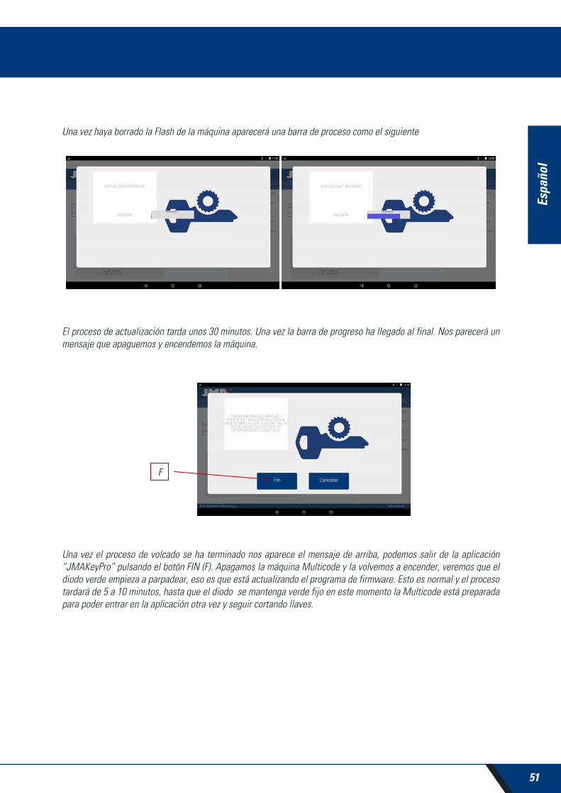
Una vez haya borrado la Flash de la máquina aparecerá una barra de proceso como el siguiente
El proceso de actualización tarda unos 30 minutos. Una vez la barra de progreso ha llegado al final. Nos parecerá un mensaje que apaguemos y encendemos la máquina.
Una vez el proceso de volcado se ha terminado nos aparece el mensaje de arriba, podemos salir de la aplicación “JMAKeyPro” pulsando el botón FIN (F). Apagamos la máquina Multicode y la volvemos a encender, veremos que el diodo verde empieza a parpadear, eso es que está actualizando el programa de firmware. Esto es normal y el proceso tardará de 5 a 10 minutos, hasta que el diodo se mantenga verde fijo en este momento la Multicode está preparada para poder entrar en la aplicación otra vez y seguir cortando llaves.

52
Espa
ñol
9.8 DIAGNÓSTICOEn la pantalla de ajuste también podemos encontrar la parte diagnóstico de la máquina, en esta parte se puede hacer pruebas del buen funcionamiento de los motores.
Una vez elegimos diagnóstico de la zona de ajustes tendremos la siguiente pantalla.
1.- Movimiento continúo. Esta función mueve los tres ejes.
2.- Avanzar eje X, el eje X avanza un tramo.
3.- Retroceder Motor X en chequeo. Manda el motor X a origen.
4.- Avanzar eje Y, el eje Y avanza un tramo.
5.- Retroceder Motor Y en chequeo. Manda el motor Y a origen.
6.- Avanzar eje Z, el eje Z avanza un tramo.
7.- Retroceder eje Z. Manda el motor Z a origen.
8.- Velocidad. Carga velocidades óptimas, en caso de reset de valores.
9.- Reset de Valores Fábrica. Resetea todo los valores de fábrica. Esta opción está protegida con password y es recomendable hacerlo con ayuda del servicio técnico de JMA.
10.- Motor V. Pone en marcha el giro del eje vertical (llaves puntos y regata).
11.- Motor H. Pone en marcha el giro del eje horizontal (llaves de serreta).
j g

Engl
ish
MULTICODEUSER MANUAL
KEY CUTTING MACHINE

54
Engl
ish
INDEX
1.- PRESENTATION AND GENERAL ASPECTS ................................................................................551.1 GENERALITIES .......................................................................................................................551.2 TRANSPORT AND PACKAGING ............................................................................................551.3 IDENTIFICATION LABEL ........................................................................................................55
2.- INSTALLATION AND CHARACTERISTICS OF THE MACHINE .................................................562.1 MAIN ELEMENTS OF THE MULTICODE ................................................................................56
2.1.1 Multicode .....................................................................................................................562.1.2 Tablet support and tablet ............................................................................................562.1.3 Power unit and power cable ........................................................................................58
2.2 INSTALLATION ......................................................................................................................602.3 MACHINE DESCRIPTION .......................................................................................................602.4 FAMILY AND TERMINOLOGY OF KEYS. ...............................................................................612.5 TECHNICAL DATA .................................................................................................................622.6 ACCESSORIES BOX ...............................................................................................................63
3.- CLAMPS ............................................................................................................................................643.1 CLAMP FOR FLAT KEYS ........................................................................................................64
3.1.1 Use of the standard clamp “MP1” ...............................................................................643.2 CLAMP FOR POINTS AND CHANNEL KEYS ..........................................................................66
3.2.1 The clamp .....................................................................................................................663.2.2 Type of limit .................................................................................................................673.2.3 Jaw model ...................................................................................................................68
3.3 ADJUSTMENT OF DIFFERENT CLAMPS ...............................................................................693.3.1 Adjust the clamps, flat keys ........................................................................................693.3.2 Adjust safety clamp .....................................................................................................70
4.- USE OF THE TABLET .......................................................................................................................724.1 CHARGING AND STARTING THE TABLET ............................................................................724.2 CHOOSE LANGUAGE .............................................................................................................72
5.- CLEANING AND SAFETY ................................................................................................................746.- MAINTENANCE ...............................................................................................................................74
6.1 ACCESS TO THE REAR PART ................................................................................................756.2 CONTROL REPLACEMENT .....................................................................................................756.3 CLEAN SWARF TRAY AREA. .................................................................................................766.4 REPLACE PRISMATIC CUTTER ..............................................................................................766.5 REPLACEMENT CYLINDRICAL CUTTER ................................................................................77
7.- WASTE ELIMINATION ....................................................................................................................787.1 PACKAGING ..........................................................................................................................787.2 SWARF ..................................................................................................................................787.3 MACHINE ..............................................................................................................................78
8.- SERVICE ............................................................................................................................................789.- SOFTWARE OPERATIONAL GUIDE ..............................................................................................79
9.1 BLUETOOTH LINK ..................................................................................................................809.2 CHANGE OF LANGUAGE .......................................................................................................829.3 KEY SCALE 1:1.......................................................................................................................829.4 SEARCHES .............................................................................................................................84
9.4.1 Searches by lock manufacturer (Standard Areas) .......................................................849.4.2 Search by automation, by type, by brand, model and year (Automation Area) ..........879.4.3 Search for keys by equivalents with another manufacturer (Equivalents Area) .........88
9.5CUTTING INFORMATION (FILE) ..............................................................................................899.5.1 Toothed key files ..........................................................................................................899.5.2 Point key file ................................................................................................................939.5.3 Channel / Slot key File .................................................................................................96
9.6 JAW SETTINGS .....................................................................................................................989.6.1 Adjust Toothed Jaw .....................................................................................................999.6.2 Points/Channel jaw adjustment ..................................................................................99
9.7 UPDATE FIRMWARE ...........................................................................................................1009.8 DIAGNOSTICS .....................................................................................................................102

55
Engl
ish
MULTICODEKEY CUTTING MACHINE
1.- PRESENTATION AND GENERAL ASPECTS
1.1 GENERALITIESThe MULTICODE duplicating machine has been designed taking into account current safety regulations in force in the E.E.C.
Personal safety involved in the use of this type of machine is only attained with a well designed programme for per-sonal safety, like the implementation and following of the recommended suggestions as well as compliance with the safety regulations contemplated in this manual.
Although the installation of the machine is not difficult, we recommend carefully reading this manual before trying to install, adjust or handle the machine.
The machine has left our factory ready for use and only needs calibrating operations for the tools to be used.
1.2 TRANSPORT AND PACKAGING The machine is inside a package with the following dimensions:
Width = 610 mm, length = 510 mm, height = 520 mm.
Machine weight plus packaging = 32 Kg.
When unpacking the machine, carefully inspect it to see if it has been damaged during transport. If you discover any anomaly, immediately notify the transporter and do not do anything with the machine until the transporter agent has made the corresponding inspection.
1.3 IDENTIFICATION LABELThe MULTICODE duplicating machine has an identification label (Fig. 1), indicating the serial or registration number of the machine, name and address of the manufacturer, EC marking and year of manufacturing.
FIG. 1
56
Engl
ish
4
2
7
65
1
8
9
10
3
11
12
13
14
15
16
18
19
.
17
2.- INSTALLATION AND CHARACTERISTICS OF THE MACHINE
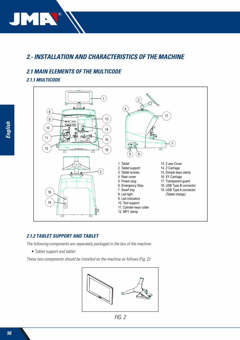
2.1 MAIN ELEMENTS OF THE MULTICODE2.1.1 MULTICODE
FIG. 2
2.1.2 TABLET SUPPORT AND TABLET
The following components are separately packaged in the box of the machine:
• Tablet support and tablet
These two components should be installed on the machine as follows (Fig. 2):
1. Tablet2. Tablet support3. Tablet screws4. Rear cover5. Power plug6. Emergency Stop7. Swarf tray8. Led light9. Led indicators10. Tool support11. Cylinder keys cutter12. MP1 clamp
13. Z axe Cover14. Z Carriage15. Dimple keys clamp16. XY Carriage17. Transparent guard18. USB Type B connector19. USB Type A connector (Tablet charge)

57
Engl
ish
MULTICODEKEY CUTTING MACHINE
1. Unthread the knobs (T1) located on the machine. (Fig. 3)
2. Install the tablet support.
3. Thread and tighten the knob to fix the tablet support on the top part of the machine.
4. Introduce the tablet into the support.
• Use and settings of the tablet support
The tablet support has different settings:
1. Height setting of the upper clamp. Turning the lever (A) clockwise, you can adjust the height of the clamp (B) to introduce the tablet. After adjustment, block it by turning the lever anticlockwise. Clamps (C) and (D) are adjusted to adapt to the size of the tablet.
FIG. 4
FIG. 3
T1
AB
C D
58
Engl
ish
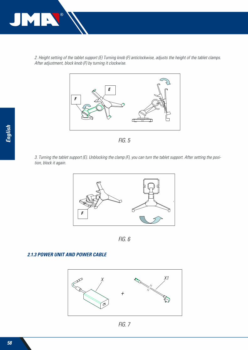
2. Height setting of the tablet support (E) Turning knob (F) anticlockwise, adjusts the height of the tablet clamps. After adjustment, block knob (F) by turning it clockwise.
3. Turning the tablet support (E). Unblocking the clamp (F), you can turn the tablet support. After setting the posi-tion, block it again.
FIG. 5
FIG. 6
2.1.3 POWER UNIT AND POWER CABLE
FIG. 7
+
X X1

59
Engl
ish
MULTICODEKEY CUTTING MACHINE
Connect the MULTICODE to the power unit (X) and connect this latter to a power outlet using the power cable (X1).
Note: Connect the 24V DC 4 pin connector with the flat face looking downwards.
FIG. 8
FIG. 9

60
Engl
ish
2.2 INSTALLATION The machine is assembled, calibrated and controlled ready for use and does not need any assembly operations. In all cases, before the first start-up, the following controls should be made:
• Connect the MULTICODE machine to adequate voltage power supply (220V 50Hz or 110V 50/60 Hz) using the supplied power unit (See section 2.1.3)
• It is very important that the electrical installation of the establishment has an earth connection. Make sure that the machine is connected to earth.
After having unpacked the machine and connected the supplied cable to the power outlet, the machine is ready for use.
Make sure the emergency button is not pressed, if it is, unblock it.
After starting the machine, the carriages will move to the start position (if they are not there already) and a green light will show on the display. (Fig. 10)
The MULTICODE machine, will only work if it is connected to the TABLET with the JMAKeyPro program. The commu-nication between the software and the machine is via Bluetooth.
This said, switch the tablet on and then activate the software. After having activated the program, a blue light will show on the display. (Fig. 10) The machine is now prepared to operate.
2.3 MACHINE DESCRIPTIONThe MULTICODE machine has been designed to cut flat, points/channel type keys. During the design phase, the mi-nimal details have been analysed to manufacture a compact machine, easy to use and that is very precise. This is a Mecatronics machine, with three stepper motors for displacement of the carriages.
In other words, we are before a very versatile machine that can be used for both flat, pointed or channel keys.
FIG. 10
OPERATION

61
Engl
ish
MULTICODEKEY CUTTING MACHINE
It reads and/or decodes flat keys with standard coding and point/channel keys using a feeler with electronic contact.
2.4 FAMILY AND TERMINOLOGY OF KEYSThe MULTICODE machine duplicates the following types of keys:
• Flat (A) and vehicle (B) type keys.
• Point (D), channel / groove (vehicles) (E) type keys.
FIG. 11
1.Head2.Limit3.Biting
4.Blade5.Rear6.Point

62
Engl
ish
2.5 TECHNICAL DATAThe main technical data is shown below:
Power supply 24V d.c-7.5 Amp.-180W Power unit: 100/240V a.c.- 50/60HZ-180W
Cutter Prismatic (Flat keys) High speed steel. Turning speed 1100 rpm
Cutter Cylindrical Hardened steel. Turning speed 12000 rpm(Point/channel or groove keys)
Standard jaw (MP1) for flat keys With four sides
Jaw for dimple/channel keys With interchangeable jaws
Displacement With flexball (ball screw) activated by stepper motors on rectified roller guides.Tool tracks X= 45mm.. Y= 45mm.
Z= 30mm.
Illumination LED diode
Dimensions Depth: 413mm
Width: 427mm
Height with support + tablet: 612mm
Height without support + tablet: 431mm
Tablet Model: Lenovo TB2-X30F
Mass 27Kg.

63
Engl
ish
MULTICODEKEY CUTTING MACHINE
2.6 ACCESSORIES BOXThe MULTICODE machine is equipped with a box for accessories for maintenance and settings (Fig. 12). The acces-sories are as follows:
FIG. 12
Spanner 18 mm
Cutter blocking rodØ4x30
Brush
Point limit set
01F Cutter
2F Cutter
Allen key 2mm
Allen key 2.5mm
Allen Key in ‘T’ 3 mm
Allen key 4mm
Jaw setting tracer RP
Allen key 5mm
Fuse: T6.3A 250V
Adjustment lever CRG
Adjustment plate RPC
03F Cutter
Jaws C and D

64
Engl
ish
FIG. 13
3.- CLAMPS
The machine consists of two clamps, one for machining flat keys and another for point and/or channel keys. The use of the two clamps for correct operation is detailed below.
3.1 CLAMP FOR FLAT KEYS
3.1.1 USE OF THE STANDARD CLAMP “MP1”
The standard clamp “MP1” is designed for reading and machining flat keys. When attaching the key, consider two aspects: Side and key limit.
• Sides 1, 2, 3 and 4 of the standard clamp “MP1”.
The different sides and characteristics of the key to be attached are indicated below:
a) Copying a key with rear support.
Side 1: keys with normal blade
Side 2: keys with narrow blade
b) Copying of keys by means attaching the key by its profile
Side 3: Key with guide in lower part
Side 4: Key with guide in upper part
Representation of standard clamp with images of different attaching (Fig. 13)
The standard clamp has 4 sides, (numbers engraved on the top part of the clamp) that allow closing the attached keys on the rear and profile. The clamp is designed to hold different models of keys. The side change is simple, leave the clamp slightly open, and manually turn the key to the desired side.

65
Engl
ish
MULTICODEKEY CUTTING MACHINE
• Key limit.
After having chosen a side of the clamp, then you have to position the key lengthwise, to do that you have to take into account the limit of the key. Depending on the model of the key, there are two types of limit:
1. Neck limit (C): This is the most common. The key is limited by means of a mechanical limit of the clamp. (Fig. 14)
2. Point limit (1, 2, and 3): The key is limited by means of the point limit supplied in the accessory box and this is placed together with the key in the standard clamp slot.
Example of key positions in side 1 and limit 2 (Fig. 15)
FIG. 14
FIG. 15
Point limit

66
Engl
ish
Image of a clamp with the numbering of the slots to make the limits. (Fig. 16)
All the necessary information about attaching the key from the JMAKeyPro software in the tablet will appear when the key code is introduced.
FIG. 16
FIG. 17
3.2 CLAMP FOR POINTS AND CHANNEL KEYSAccording to the key to be machined or coded, follow the indications that appear in the JMAKeyPro software in the tablet. The main indications refer to the following:
3.2.1 THE CLAMP
It indicates which model of clamp you should use.
Both point and channel keys can be introduced into the clamp. In the case that the clamp has to be removed, follow these steps:
1) Raise the transparent guard.
2) Loosen screw (T2) and remove the clamp by moving it toward the operator.
3) Introduce the clamp (previously cleaning the housing) into the dovetail and raise it to the top.
4) Lock the clamp by turning screw (T2).
Side 1: Limits 1, 2, 3. Side 2: Limits 1, 2. Side 3: Limits 1, 2. Side 4: Limits 1, 2.
T2

67
Engl
ish
MULTICODEKEY CUTTING MACHINE
3.2.2 TYPE OF LIMIT
Both point and channel keys can be introduced into the clamp, with neck limit or with point reference. The first (with C limit) have to be supported against the jaws while the others (point limit) have to be supported with reference in one of the channels (1-2-3), as indicated in the JMAKeyPro software. For this operation use the point limit that is in the accessory box, after having positioned the key, remove it.
• Neck limit
• Point limit (1-2-3)
FIG. 18
FIG. 19
Point limit

68
Engl
ish
3.2.3 JAW MODELS
The clamp has two standard jaws, a fixed one (A) and a mobile one (B). One of the important characteristics of the jaws is that they have two sides to attach different models of keys. Both the fixed jaw and the mobile one, have two sides, 1 and 2.
The following steps are to change the jaw or the side of the jaw:
1) Unscrew the knob (T3) to the end
2) Push the jaw(s) with your fingers from its rear part removing it towards the operator. (Fig. 20)
3) Clean the jaw housing area with the brush.
4) Change the jaw of the side and fully introduce it.
Note: The information about the jaws to be used appears in the JMAKeyPro software in the tablet.
FIG. 20
T3

69
Engl
ish
MULTICODEKEY CUTTING MACHINE
3.3 ADJUSTMENT OF DIFFERENT CLAMPSThe machine has different areas (flat and safety) to adjust the clamps and take readings.
3.3.1 ADJUST THE CLAMPS, FLAT KEYS
This can be used both for adjusting the cutter or the reader. After adjustment, it can be used to take key readings.
The following steps are for adjusting the cutter:
1) Place the CRG (T4) in the clamp MP1 on side 1.(Fig.21)
2) Go to the SETTINGS menu, select settings -> adjust zero-machines (flat key) -> Cutter.
3) Select the clamp and then press the cutter adjustment button.
To adjust the reader of flat keys.
1) Place the CRG (T4) in the clamp MP1 on side 1.(Fig.21) (Fig. 22)
2) Place the tracer in the testing position by turning the axis (T5)
FIG. 21
FIG. 22
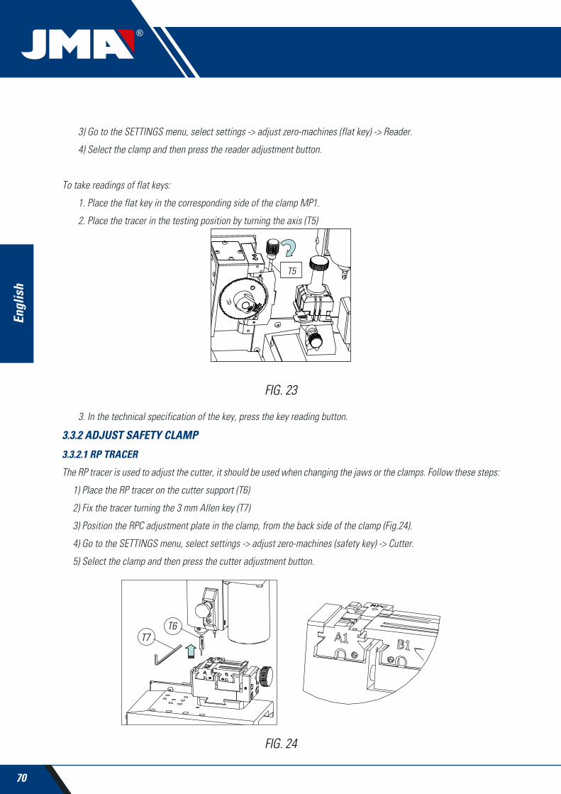
70
Engl
ish
3) Go to the SETTINGS menu, select settings -> adjust zero-machines (flat key) -> Reader.
4) Select the clamp and then press the reader adjustment button.
To take readings of flat keys:
1. Place the flat key in the corresponding side of the clamp MP1.
2. Place the tracer in the testing position by turning the axis (T5)
3. In the technical specification of the key, press the key reading button.
3.3.2 ADJUST SAFETY CLAMP
3.3.2.1 RP TRACER
The RP tracer is used to adjust the cutter, it should be used when changing the jaws or the clamps. Follow these steps:
1) Place the RP tracer on the cutter support (T6)
2) Fix the tracer turning the 3 mm Allen key (T7)
3) Position the RPC adjustment plate in the clamp, from the back side of the clamp (Fig.24).
4) Go to the SETTINGS menu, select settings -> adjust zero-machines (safety key) -> Cutter.
5) Select the clamp and then press the cutter adjustment button.
FIG. 23
FIG. 24
T6T7
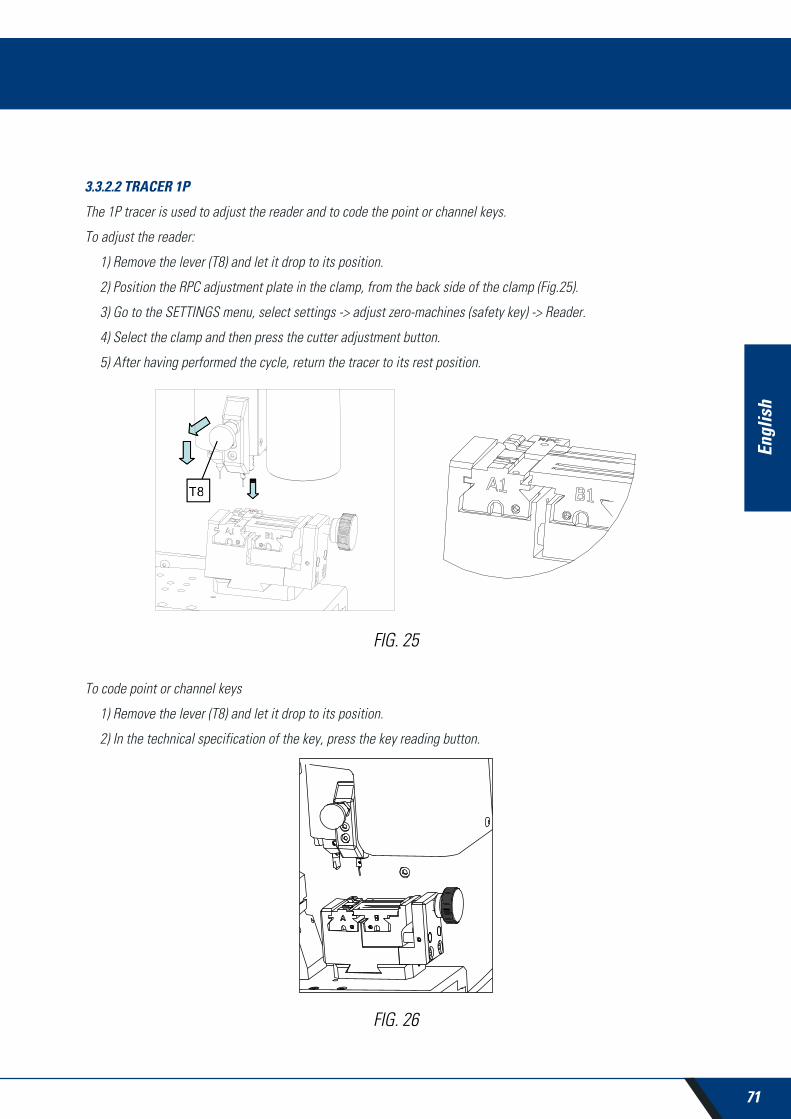
71
Engl
ish
MULTICODEKEY CUTTING MACHINE
3.3.2.2 TRACER 1P
The 1P tracer is used to adjust the reader and to code the point or channel keys.
To adjust the reader:
1) Remove the lever (T8) and let it drop to its position.
2) Position the RPC adjustment plate in the clamp, from the back side of the clamp (Fig.25).
3) Go to the SETTINGS menu, select settings -> adjust zero-machines (safety key) -> Reader.
4) Select the clamp and then press the cutter adjustment button.
5) After having performed the cycle, return the tracer to its rest position.
To code point or channel keys
1) Remove the lever (T8) and let it drop to its position.
2) In the technical specification of the key, press the key reading button.
FIG. 26
FIG. 25
T8T8
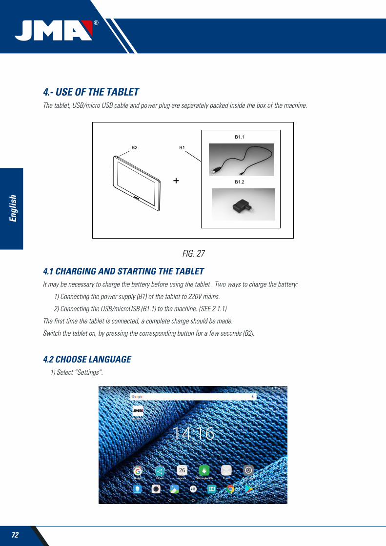
72
Engl
ish
4.- USE OF THE TABLETThe tablet, USB/micro USB cable and power plug are separately packed inside the box of the machine.
4.1 CHARGING AND STARTING THE TABLETIt may be necessary to charge the battery before using the tablet . Two ways to charge the battery:
1) Connecting the power supply (B1) of the tablet to 220V mains.
2) Connecting the USB/microUSB (B1.1) to the machine. (SEE 2.1.1)
The first time the tablet is connected, a complete charge should be made.
Switch the tablet on, by pressing the corresponding button for a few seconds (B2).
4.2 CHOOSE LANGUAGE1) Select “Settings”.
FIG. 27

73
Engl
ish
MULTICODEKEY CUTTING MACHINE
2) Select “Language and text introduction”.
3) Select “Language”.
4) Move down the menu and select your language.

74
Engl
ish
5) To finish, press the circle.
Note: For all the MULTICODE functions, follow that indicated in the JMAKeyPro software and in the manual.
For all other indications, follow that indicated the quick guide of the tablet.
5.- CLEANING AND SAFETYWe recommend following these guidelines for the cleaning:
• Maintain all functional parts of the machine as clean as possible, removing with the brush all machining swarf.
• Never use compressed air to clean the work area of swarf, this could enter the operational parts.
We recommend following these guidelines for your safety:
• Do not try to start or manipulate the machine until all safety measures, installation instructions, operator guide and maintenance procedures have been completed and understood.
• Always disconnect from the power supply, before performing any cleaning or maintenance.
• Work with dry hands.
• Make sure the machine is earthed.
6.- MAINTENANCEBefore starting any type of maintenance operation, the following requirements should be completed.
• You should never carry out any operation while the machine is running.
• You should disconnect the cable from the power supply.
• The indications in the manual should be strictly followed.
• Only use original spare parts.
The machine does not need any special maintenance, only revise and if applicable, replace worn pieces, for example, cutters, jaws, feelers...
Note: Use lubrication products, for preventive maintenance of the machine. Avoid the product from making contact with electronic parts.
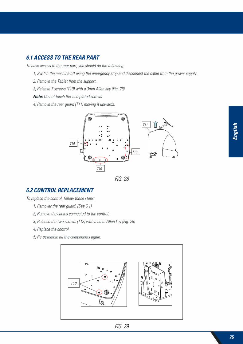
75
Engl
ish
MULTICODEKEY CUTTING MACHINE
6.1 ACCESS TO THE REAR PARTTo have access to the rear part, you should do the following:
1) Switch the machine off using the emergency stop and disconnect the cable from the power supply.
2) Remove the Tablet from the support.
3) Release 7 screws (T10) with a 3mm Allen key (Fig. 28)
Note: Do not touch the zinc-plated screws
4) Remove the rear guard (T11) moving it upwards.
6.2 CONTROL REPLACEMENTTo replace the control, follow these steps:
1) Remover the rear guard. (See 6.1)
2) Remove the cables connected to the control.
3) Release the two screws (T12) with a 5mm Allen key (Fig. 29)
4) Replace the control.
5) Re-assemble all the components again.
FIG. 28
FIG. 29

76
Engl
ish
6.3 CLEAN SWARF TRAY AREATo remove the swarf tray, do the following:
1) Remove the swarf box, pulling it outwards.
2) Remove the swarf, using the brush.
3) Re-introduce the tray taking it to the bottom following the two lines (T13) marked in black on the chassis (Fig. 30)
6.4 REPLACE PRISMATIC CUTTER.To replace the cutter, do the following:
1) Switch the machine off using the emergency stop and disconnect the cable from the power supply.
2) Raise the front plastic guard.
3) Introduce the blocking rod (T14), which is in the accessory box (Fig. 31)
4) Unscrew the cutter fixing screw (T15) with the 18mm spanner.
Note: Thread to the left
5) Replace the cutter, block the nut, remove the rod from the hole and place the protection cover.
NOTE: In the case of installing a new cutter, the cutter will have to be adjusted
(See sect. 3.3.1)
FIG. 30

77
Engl
ish
MULTICODEKEY CUTTING MACHINE
6.5 REPLACEMENT CYLINDRICAL CUTTER 1) Switch the machine off using the emergency stop and disconnect the cable from the power supply.
2) Raise the front plastic guard.
3) Unscrew the prisoner screw (T16) with a 3mm spanner (T17) and remove the cylindrical cutter (T18). Fig. 32
4) Replace the cutter, pushing upwards to the limit.
5) Tighten the prisoner screw. (T16)
FIG. 31
FIG. 32

78
Engl
ish
7.- WASTE ELIMINATIONWaste is understood to be any substance or object originating from human activities or natural cycles, abandoned or designed to be abandoned.
7.1 PACKAGING• Because the packaging of the MULTICODE machine is made from cardboard, it can be recycled as packaging.
• As waste, it is classified as solid urban waste and therefore can only be deposited in special containers for cardboard.
• The moulds that protect the machine inside the cardboard box, are made from polymer also classified as solid urban waste and therefore, can only be eliminated in normal installations for the elimination of solid waste.
7.2 SWARF• The residues originating from the copying of key are classified as special waste, but are included in the group of solid urban waste, for example like a metal washing pad.
• This waste is eliminated according to the classification of the laws in force in the EU, and should be taken to the special waste elimination companies.
7.3 MACHINE• Before scrapping the machine, it should me put out of service, cutting the power supply and separating the pieces of plastic from the pieces of metal.
• After doing this, all the waste can be eliminated, according to the laws in force in the country where the ma-chine is used.
8.- SERVICEAlejandro Altuna has a technical service for all clients of the MULTICODE machine.
To assure complete safety for the operator and the machine, any work not indicated in this manual, should be carried out only by the manufacturer or technical service. If there is any doubt about handling the machine, consult the ad-dress indicated at the end of this manual.
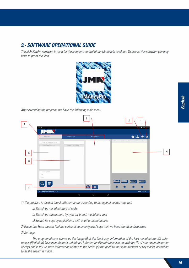
79
Engl
ish
MULTICODEKEY CUTTING MACHINE
9.- SOFTWARE OPERATIONAL GUIDEThe JMAKeyPro software is used for the complete control of the Multicode machine. To access this software you only have to press the icon.
After executing the program, we have the following main menu.
1) The program is divided into 3 different areas according to the type of search required.
a) Search by manufacturers of locks.
b) Search by automation, by type, by brand, model and year
c) Search for keys by equivalents with another manufacturer
2) Favourites Here we can find the series of commonly used keys that we have stored as favourites.
3) Settings
The program always shows us the image (I) of the blank key, information of the lock manufacturer (C), refe-rences (R) of blank keys manufacturer, additional information like references of equivalents (E) of other manufacturers of keys and lastly we have information related to the series (S) assigned to that manufacturer or key model, according to as the search is made.

80
Engl
ish
9.1 BLUETOOTH LINKThe Multicode machine comes with a Tablet, with the application so the Multicode can function, but the JMAKeyPro application can be installed in any Tablet with a screen of 8” or more and with Android 4.4.2 “Kitkat” or later. In the case of changing the Tablet, and using another Tablet to control the Multicode, first you will have the couple the Tablet and the Multicode machine. To do that, proceed as follows. Switch on the Multicode machine and see if the green diode comes on steady, this means that the machine is initialized and ready. Make sure the Bluetooth diode is not on, this means that the machine is already connected to a Tablet and therefore it cannot be coupled to another Tablet. If the blue Bluetooth diode is off, we can continue with the coupling.
• Enter into the settings section (A) of the Android Tablet.
• In settings, we go to Bluetooth (B) in the section of wireless connections and networks:

81
Engl
ish
MULTICODEKEY CUTTING MACHINE
In the next screen of Bluetooth devices, we assure that the Bluetooth of the Tablet is activated, so we can search all the devices within its reach, (the scope is 15 metres, without any type of obstacle, if there is an obstacle this scope is reduced). Search for the Bluetooth device named “JMA Multicode”.
After choosing the device we will see the message of “Coupling Device” on the screen, it is an automatic process, there is no need to introduce any code or password for coupling. After the coupling process has finalized “JMA Mul-ticode” should appear in “Synchronized Devices”.
Once we have “JMA Multicode” in synchronized devices, we can enter the “JMAKeyPro” application and once w enter the application, after a few seconds, the blue connection diode of the machine will come on to indicate that the communication between the program and Multicode is re-established.

82
Engl
ish
9.2 CHANGE OF LANGUAGEThe language can be changed in the “JMAKeyPro” program, to do that go to the settings section.
In settings, we choose the language in which we want the program to work and wait for the language to appear automatically.
10.3 KEY SCALE 1:1The program allows us to see the key in scale 1:1 at any time during a search, this allows us to check the physical key we have on the image generated by the program at 1:1 scale. To obtain the image of the key at 1:1 scale, click or touch the image of the key (1).

83
Engl
ish
MULTICODEKEY CUTTING MACHINE
After pressing on the image a window appears on the screen with the 1:1 scale image of the key. This window has the peculiarity that the entire screen is no sensitive to the touches by the hand or the key, which allows us to position the physical key over the 1:1 scale image. The only area sensitive to touch is the cancel button (C) that allows us to return to the main search menu.
NOTE: Remember that the image of the main menu is not 1:1 scale and depends on the size of the Tablet screen, while after pressing the image you will obtain a 1:1 scale image.

84
Engl
ish
9.4 SEARCHES9.4.1 SEARCHES BY LOCK MANUFACTURER (STANDARD AREAS)
This screen is the most versatile because it allows us to make different types of searches according to the criteria we choose. We are going to define the different types of searches we can perform.
Case 1: The most general search is introducing the lock manufacturer and press search.
When we enter or select a lock manufacturer, the system makes an automatic search. The search is made by intro-ducing the name into the box corresponding to manufacturer search, as we type the letters, the system will filter the possible manufacturers with those letters.

85
Engl
ish
MULTICODEKEY CUTTING MACHINE
Case 2: Define a JMA key blank and see, which the series, related to that key is.
When we enter or select a JMA key reference, the system makes an automatic search. The search is made by intro-ducing the name into the box corresponding to the JMA blank key reference, as we type the letters, the system will filter the possible manufacturers with those letters.
Case 3: The lock system is defined in the software, introduce part of this name and press search. This search will give you all the possibilities containing that word.
In the search by lock system, we should press the search button (F) to make the search and later press the erase button (D) to make any other search with another word.

86
Engl
ish
Case 4: Directly search for a file we want to use for machining.
This search for the series that contain the exact file we have introduced in the file search box.
In the search by lock system, we should press the search button (F) to make the search and later press the erase button (D) to make any other search with another word.
Case 5: In the case we have the key code, either the direct or the indirect code, we can make a search by only intro-ducing the code.
This searches the series that coincide with the code of the key.
In the search by lock system we should press the search button (F) to make the search and later press the erase button (D) to make any other search with another word.
Specification search box
F
D
Code search box
F
D

87
Engl
ish
MULTICODEKEY CUTTING MACHINE
Indirect code: There is no relation with the biting.
e.g. key OP-D file 227 code D1200 -> biting 3344443123
The dots (.) in D series... 0001-2000 indicate the digits of the key series
Direct code: There is a direct relation with the biting.
e.g. key TE-81 file 476 code 12345A -> biting 12345
The dots (.) in A series... 1234567890 indicate the biting of the key
9.4.2 SEARCH BY AUTOMATION, BY TYPE, BY BRAND, MODEL AND YEAR (AUTOMATION AREA)
This search allows us to know the JMA key model used by an automation vehicle model (Car, Truck or Motorbike), in many cases the client can come with the original key of the vehicle and identifying the profile can be a difficult task, we can simply see which JMA key model is compatible with that model of automobile by the year of construction of that model.
To do that, all you need do is to define the search fields and press the search button (F) to perform the search and the clear/erase button (D) to make a new search. In this case, we have two boxes with results. The information box of the key (I) used by the selected vehicle, also giving information about the transponder system it uses.
In the following example, we can see how the FOCUS® car model of the brand FORD®, from the years 2005-2010 has a key similar to the JMA TPX2FO-24P, which includes the TPX2 transponder and blade profile FO-24P, which is cloneable on an original key, which includes a Texas® Crypto chip.

88
Engl
ish On the other hand, the software notifies when we have all the necessary information to cut the key, in the series box
(S). In this case, it notifies that with file 255P we can cut this key.
9.4.3 SEARCH FOR KEYS BY EQUIVALENTS WITH ANOTHER MANUFACTURER (EQUIVALENTS AREA)
This section of the program allows us to introduce references of keys that are not JMA references and will tell us the JMA equivalent and on the other hand it will give tell us if the key can be cut or not in the Multicode.
The selector include (P) allows us to search those words that include the wanted reference, if it is chosen, it will only show the keys that start with that reference.
In the search by key reference system we should press the search button (F) to make the search and later press the erase button (D) to make any other search with another word.

89
Engl
ish
MULTICODEKEY CUTTING MACHINE
9.5 CUTTING INFORMATION (FILE)Once the program is connected to the Multicode in the JMAKeyPro program, we have access to see the technical information for cutting the key. If there is no link with the Multicode machine, this information is not accessible. We can differentiate the files into two families, according to the attaching area and the cutting tool to be used, therefore, we can denominate the following divisions:
a) Toothed key files Keys cut with the horizontal tool and where we have the MP1 jaw with four sides, the pos-sibility of changing to other jaws, personalization of special key profiles.
b) Point or channel key files Keys cut with vertical tool, the jaw of this area has interchangeable clamps according to the model of key, the software will notify us of the clamp needed at all times. The machine will have to be adjusted each time the clamps are changed.
9.5.1 TOOTHED KEY FILES
When searching for a key (AZBE) or a biting code (e.g. 15000J) we can see its mechanical data by clicking on top of the file (in this case 507).
When clicking on the file we enter the file screen where we can see the technical data of the key and it will tell us how to attach the key, (side of the jaw, limit...).

90
Engl
ish
On one hand we have the information part (I) related to the key, the name of the file, the information of the cutting of the key in profile.
On the other hand, we have the code introduced, in this case 15000 and the biting related to this code 32248.
On another hand, we have essential information (J) about the cutter, feeler and jaw for this key, initially they are the standards already set in the machine. Clicking on the icon to view ( ) we will have an image of each element.
Cutter FP34 Feeler-Reader toothed key Jaw MP1
To remove the pre-visualization of each element, click on the image again.
Where and how to attach the key?
In jaw (see reference M in the drawing above) it gives us two details, on one hand the jaw in which the key is attached and on the other the side of the jaw. In this example MP1/1 indicates Jaw=MP1 and side of the jaw=1. If in this box it shows MP1/2, then Jaw=MP1 and side of the jaw=2.
The limit is referenced by the red line drawn on the representation of the cut of the key. That way, in this example it indicates Limit 0 and in the neck of the key. In the cases 1, 2 or 3 usually a limit is made at the point of the key, and using the point limit plate in the channels of face 1 of the jaw MP1.
See Chapter 3.1 referring to the tooth jaw, to see the limits and the indications of how to attach the key.
We can perform two actions in the file.
A) Reading of the key :
We can attach an original key as if we were going to machine it and later opening the tooth reader, pressing the read button to read the key by electronic contact.
After reading the key, the program tells us the biting code and shows us the heights it read in the cutting represen-tation. Later when re-commanding the cutting of the key we can cut according to the official heights (theoretical) of the manufacturer or according to the heights read on the key.

91
Engl
ish
MULTICODEKEY CUTTING MACHINE
B) Key machining :
The key machining is just as easy as reading, it consists of attaching the key well and after introducing the biting cutting either directly (or by obtaining a code) or after the reading of an original key, we command the machining.
The biting of the key can be changed at any time by writing in the biting box
The information given to us by the file data screen is the same as in the case of reading but in the case of machining a biting key we can use different machining operations:
1) Height Control: Normal or Self-adjust cutting
The Multicode machine is already adjusted, and does not need to obtain a height reference each time that a toothed key is machined. As the reference of the key is given by its blade and this is already calibrated, usually a normal machining is used, but in the case of double biting keys (car keys), once one side is machined, there is no surface to calibrate the key for machining the second side of the key, therefore it is convenient to use side 3 or side 4 for attaching by channels, when using this side of the key the reference changes, therefore a new reference is needed, for this case we can use the self-adjusting cutting mode. The self-adjustment mode does the following before starting to machine, it takes the reference above the key, the file has the height data of the blank key, therefore the reference is taken this way, that way the key can be in another position and the machine adjusts by electronic contact. In the drawing below, we can see how that choosing between the two options, or nothing, the normal option is that selected by default.

92
Engl
ish
2) Height for machining: Theoretical or Read Height
As commented in the previous section, once a key has been read we have the values of the previously read keys. The program allows us to cut the key with the theoretical “original” values marked by the manufacturer or to the contrary cut the key with the read height values, with the error that this involves, but in old locks that are already vitiated, this could be the best option.
Machining a key with a read height can be combined with self-adjustment.
3) Cutting type: Normal, flat or ideal
Lastly we can change the cutting type we want to perform on the key, initially the file has a cutting type pre-established by the manufacturer, but the cutting type can be combined. The cutting types are as follows:

93
Engl
ish
MULTICODEKEY CUTTING MACHINE
The cutting types are as follows:
NORMAL: For the traditional automobile keys and door locks.
IDEAL: This is the most innovative that can be found in automobile locks, with this type of cutting the union be-tween the angles of the biting is automatically defined by the machine, establishing codlings with variable angles. This facilitates the displacement of the key and extends the life cycle of the lock.
FLAT: This is used above all in automobile locks, in which the edges of the biting are eliminated to facilitate the displacement of the pistons or plates when introducing the key into the lock.
9.5.2 POINT KEY FILE
Following the compatibility with the Avantcode machine and the Xcode, the Multicode machine has the same names of files. That is why the files of the point and channel keys in “P”, 1P, 2P ...
Access to the file is the same way as in the toothed key, by searching for a key (STS) or a tooth code we can see the series related to that manufacturer or code and by clicking on the file (in this case 305P) we can have access to the mechanical information.

94
Engl
ish
Once we have entered into the file we can see the data of the key In this case we have a key with 3 axes on face A/C and another axis on the lateral Face B/D.
On one hand we have the information part (I) related to the key, the name of the file, series, the blank key that in this case is ORIGINAL.
On the other hand, we have the biting code introduced
FACE A: Axis 1:1234
Axis 2: 12312
Axis 3: 1010
FACE B:
Axis 1: 1010101010
On another hand, we have essential information (J) about the cutter, feeler and jaw for this key, initially they are the standards already set in the machine. Clicking on the icon to view we will have an image of each element.
Cutter 2F Feeler-1P Jaw A1 B1
To remove the pre-visualization of each element, click on the image again.
Where and how to attach the key?
In jaw (see reference M in the drawing above) gives us another two details, on one hand the jaw which is where the key is attached and on the other side of the jaw (take into account that the clamps are reversible, A1 is one side of the clamp and A2 is the opposite side, any change of face will require an adjustment of the jaw and the 1P reader sp that machine is well adjusted).

95
Engl
ish
MULTICODEKEY CUTTING MACHINE
The limit is referenced by the red line drawn on the representation of the cut of the key. That way, in this example it indicates Limit 0 and in the neck of the key. In the cases limit 1 or 2 the point of the key, and using the point limit plate in the channels of face 1 of the jaw MP1.
See Chapter 3.2 referring to the tooth jaw, to see the limits and the indications of how to attach the key.
We can perform two actions in the file.
A) Key reading
Like in the case of the toothed keys in the reading of keys shows us the biting code of the key and on the other hand the read height of the key.
The point and channel keys are read with the 1P feeler that already includes the vertical head. See Chapter 3.3.2.2
B) Key machining
The key machining is just as easy as reading, it consists of attaching the key well and after introducing the biting cutting either directly (or by obtaining a code) or after the reading of an original key, we command the machining.
The biting of the key can be changed at any time by writing in the biting box.

96
Engl
ish
Attention should be given to the cutter installed in the machine, because although the cutters are standard and the machine performs the circular interpolation according to the width of the circle at the base of the spike, the lateral angle is given by the angle of the tool therefore it is necessary to use the adequate tool. The standard cutters supplied with the Multicode are as follows:
CUTTER 1F => Base = 2.5 mm Angle 0º (Straight cutter for channel keys for automation).
CUTTER 2F => Base = 0.4 mm Angle = 90º
CUTTER 3F => Base = 0.4 mm Angle = 100º
The information given to us by the file data screen is the same as in the case of reading but in the case of machining a point key there are only two different machining operations:
4) Height for machining: Theoretical or Read Height
As commented in the previous section, once a key has been read we have the values of the previously read keys. The program allows us to cut the key with the theoretical “original” values marked by the manufacturer or to the contrary cut the key with the read height values, with the error that this involves, but in old locks that are already vitiated, this could be the best option.
9.5.3 CHANNEL / SLOT KEY FILE
The channel / slot keys for automation are machined in the same area that the point keys are machined. In this case a special tool is used, it is the F1 which is a straight tool (for lateral cutting of the key), different to that of point keys (2F 90º and 3GF 100º)
The method for reading the key is similar to the point key because it uses the same feeler-tool 1P that comes incor-porated into the vertical head. We are going to see a couple of examples to see the properties of file, in this case the examples are with the key TP00FI-16P (channel key, the biting are characterized in a channel in the blade) and the key TP00FO-24P (channel key, characterized for not having biting on the edge of the key).
In these two keys we can find the tooth code or have access to the key by writing the name of the key.

97
Engl
ish
MULTICODEKEY CUTTING MACHINE
We are going to see the file of each key in the following drawing. In the case of the TP00FI-16P key (channel) we have searched for DE11056 and in the case of the key TP00FO-24P (channel) we have searched for code 2500.
On one hand we have the information part (I) related to the key, the name of the file, series, the blank key that in this case is TP00FI-16P and TP00FO-24P.
On the other hand we have the tooth code obtained from the original code of the key:
TP00FI-16P -> Code: DE11056 -> Biting: DDCCDCAA
TP00FO-24P -> Code: 2500 -> Biting: 5443543132
On another hand, we have essential information (J) about the cutter, feeler and jaw for this key, initially they are the standards already set in the machine. Clicking on the icon to see ( ) we have an image of each element and in the case of the TP00FO-24P key it shows us in which position of the jaw the point limit plate of the key is introduced.
Key TP00FO-24P
Cutter 1F Feeler-1P Jaw A1 B1 Limit 1
Key TP00FI-16P
Cutter 1F Feeler-1P Jaw A1 B1 Limit 1

98
Engl
ish
To remove the pre-visualization of each element, click on the image again.
Where and how to attach the key?
In jaw, we receive two details, on one hand the jaw which is where the key is attached and on the other side of the jaw (take into account that the clamps are reversible, A1 is one side of the clamp and A2 is the opposite side, any change of face will require an adjustment of the jaw and the 1P reader sp that machine is well adjusted).
The limit is referenced by the red line drawn on the representation of the cut of the key. That way, this example shows us Limit 0 for the TP00FI-16P key (at the neck of the key) and Limit 1 in the case of the TP00FO-24P key (at the point of the key). In the case of Limit 1 using the point limit plate in the channels of face A1 of jaw A1
9.6 JAW SETTINGSThe Multicode machine is equipped with an electronic contact in the two tools, either the horizontal tool to cut toothed keys, either the vertical tool to cut point and channel keys are isolated and have an electronic sensor that detects collision or contact with the key or the jaw. This capacity of the machine allows us to adjust the machine using the CRG adjustment tools (toothed key part in the MP1 jaw) for the horizontal tool and the RP tool (points/channel key part in the A1 B1 jaw) placed in the tool holder of the vertical axis.
Access to the adjustment of the jaws is via the same area in both cases, go to settings (A) of the application and then choose the adjustment area (B).
LimitLimit

99
Engl
ish
MULTICODEKEY CUTTING MACHINE
9.6.1 ADJUST FLAT KEY JAW
In the jaw adjustment menus we select the jaw (S) we want to adjust. In this case, we select flat keys adjustment (flat key).
Adjustment of the toothed jaw is very simple, take the tool CRG and place it in face 1 of the jaw we are going to use (See Chapter 3.3.1 for placement of CRG in the jaw). In the menu we see, we can choose the jaw (M) we want, and after selecting the jaw, we press the button to adjust the part of the cutter (F); the adjustment process is automatic.
NOTE: The settings area is very important, the cutter fp34, crg has no swarf.
If we adjust the MP1 jaw... it is convenient also to adjust the reader of the toothed keys on the cutter. After finishing the adjustment of the cutter, remove the biting reader and without moving th CRG adjust the reader pressing the adjustment button (L)
9.6.2 POINTS/CHANNEL JAW ADJUSTMENT
In the jaw adjustment menus we select the jaw (S) we want to adjust. In this case, we select safety keys adjustment.
Adjusting the safety keys jaw is very simple, you have to take the RP tool and put it in the tool holder of the vertical axis (See Chapter 3.3.2.1 for the RP placement in the vertical head). In the menu we see, we can choose the jaw (M) we want, and after selecting the jaw, we press the button to adjust the part of the cutter (F); the adjustment process is automatic.
NOTE: The settings area is very important, the rp tool and the jaw have no swarf.
If we adjust the jaw A1... on the vertical head, it is also convenient that we adjust the safety keys reader 1P (See Chapter 3.3.2.2 for 1P placement). After finishing the adjustment of the vertical head in the cutter area with RP, lower the safety keys reader 1P and without moving the jaw A1... adjust the reader pressing the adjustment button (L).

100
Engl
ish
9.7 UPDATE FIRMWAREThe Firmware updating process is automatic, because when the program starts and connects to the Multicode it checks the version of the same and if it is not adequate it jumps to the updating window.
Access to this same window can be obtained through “JMAKeyPro” Adjustments and clicking on the part of updating.
NOTE: It is only recommendable to make the update when it jumps to a later or higher version of the software. It is very important not to disconnect the machine until finishing the downloading process.
The updating process is very simple once we are in the following updating screen, we press ACCEPT and the process starts automatically. The green diode of the machine will start to flash and will show us the following message:

101
Engl
ish
MULTICODEKEY CUTTING MACHINE
After having erased the Flash memory of the machine a process bar will appear with the following:
The updating process will take 30 minutes Once the progress bar has reached its end. A message will appear for us to switch the machine off and on.
After the downloading process has finished, the above message appears, we can exit the “JMAKeyPro” application pressing the button END (F). We switch off the Multicode machine and then switch it on again, we will see the green diode flash, that is because the firmware program is updating. This is normal and the process will take from 5 to 10 minutes, until the diode becomes steady green, at that moment the Multicode is prepared to enter the application again and continue cutting keys.
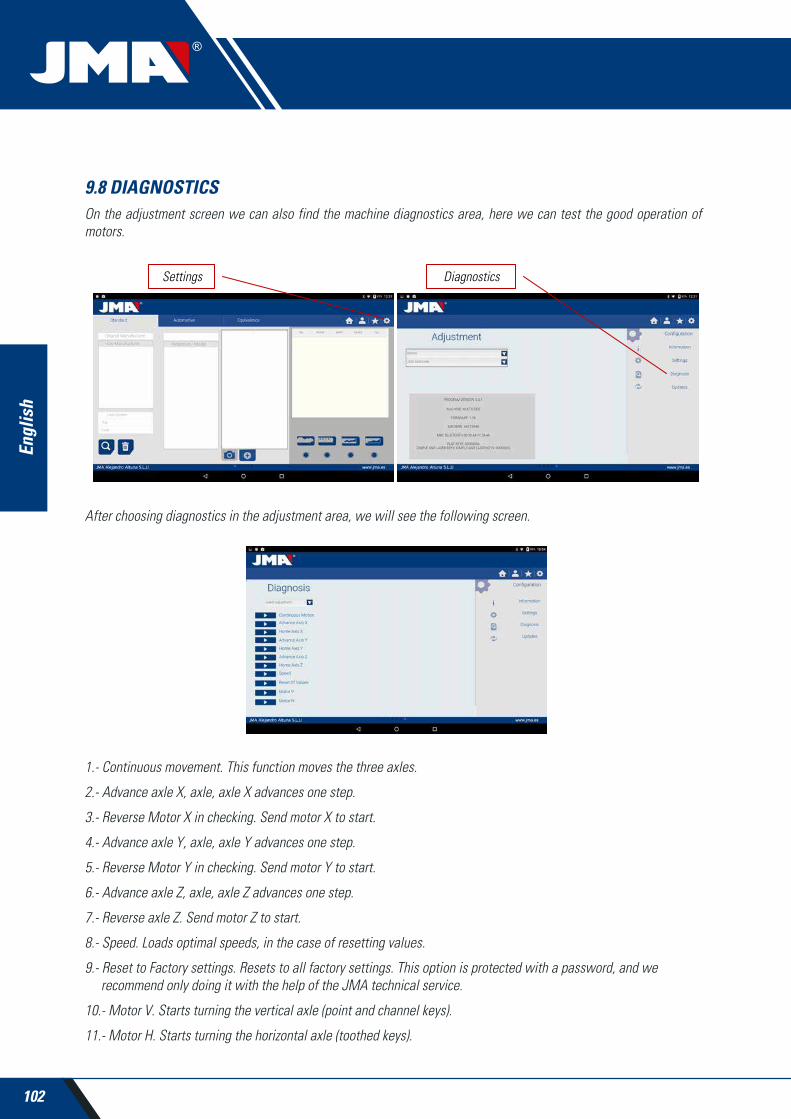
102
Engl
ish
9.8 DIAGNOSTICSOn the adjustment screen we can also find the machine diagnostics area, here we can test the good operation of motors.
After choosing diagnostics in the adjustment area, we will see the following screen.
1.- Continuous movement. This function moves the three axles.
2.- Advance axle X, axle, axle X advances one step.
3.- Reverse Motor X in checking. Send motor X to start.
4.- Advance axle Y, axle, axle Y advances one step.
5.- Reverse Motor Y in checking. Send motor Y to start.
6.- Advance axle Z, axle, axle Z advances one step.
7.- Reverse axle Z. Send motor Z to start.
8.- Speed. Loads optimal speeds, in the case of resetting values.
9.- Reset to Factory settings. Resets to all factory settings. This option is protected with a password, and we recommend only doing it with the help of the JMA technical service.
10.- Motor V. Starts turning the vertical axle (point and channel keys).
11.- Motor H. Starts turning the horizontal axle (toothed keys).
Settings Diagnostics


JMA SPAIN JMA ALEJANDRO ALTUNA, S.L.U.Tel +34 943 79 30 00Fax +34 943 79 72 43Bidekurtzeta, 6 P.O.Box - Apdo. 7020500 Arrasate - MondragónGipuzkoa – [email protected]
JMA FRANCEJMA FRANCE SASTel +33 01 39 22 42 10Fax +33 01 39 22 42 11Technoparc13, rue Edouard JeanneretF- 78306 Poissy [email protected]
JMA POLSKA JMA POLSKA Sp. z.o.o.Tel +48 42 635 12 80Fax +48 42 635 12 85
JMA PORTUGALALTUNA PORTUGAL COMERCIO DE CHAVES UNIPESSOAL, LDA.Tel +351 219 947 470Fax +351 219 947 471Rua de Goa Nº222690-356 Santa Iria de [email protected] JMA UKSKS LTDTel +44 144 229 1400Fax +44 144 286 3683Unit 2, Canalside Northbridge RoadBerkhamstedHerts HP4 [email protected]
JMA MAROC JMA MAROC S.A.R.L.Tel +0520 150 535Fax +0520 150 53683,85 Bd Oued ZIZ, El [email protected]
JMA INDIAJMA KEYS INDIA PVT. LTDTel +91 124 428 5450Fax +91 124 428 5451H-239 & H-240, Sushant Shopping Arcade Sushant Lok-1, Block B122002 Gurgaon (Haryana)[email protected]
JMA MEXICOLLAVES ALTUNA DE MEXICO S.A de C.VTel +52 33 3777 1600Fax +52 33 3777 1609Av. Aviación No. 5520Col. San Juan de OcotánC.P. 45019 Zapopan, [email protected]
JMA PERUJMA PERU S.A.C.Tel +51 639 9300Av. Los Paracas 130, Urbanización Salamanca,Distrito Ate, [email protected]
JMA USAALTUNA GROUP USA INC.Tel +1 817 385 0515Fax +1 817 385 48501513 Greenview Drive 75050 Grand [email protected]
JMA ARGENTINA JMA ARGENTINA S.A.Tel +54 336 4 462 422Fax +54 336 4 462 422Av. Central Acero Argentino Oeste 678Parque industrial COMIRSA2900 San Nicolas (Prov. Buenos Aires)[email protected]
JMA URUGUAYJMA URUGUAY S.A. Tel +598 2908 1175 Fax +598 2900 6681Mercedes 1420 11100 [email protected]
Member Of
Tel +34 943 79 30 00Fax +34 943 79 72 43
Bidekurtzeta, 6 P.O.Box - Apdo. 7020500 Arrasate - Mondragón
Gipuzkoa – SPAINwww.altuna.com
JMA WORLDWIDE
ALTUNA GROUP HEADQUARTERS