instruccionesparalainstalaciÓn usoymantenimiento … · 2019-08-29 · de este aparato.este...
TRANSCRIPT
INSTRUCCIONES PARA LA INSTALACIÓN
USO YMANTENIMIENTO
ESTUFADEPELLET
Por favor mantener estas instrucciones a mano para futuras referencias.
1
CONTENIDO1.- REQUERIMIENTODE COMBUSTIBLE............................................................................................... 1
2.- CARACTERÍSTICASDEL CALEFACTOR...............................................................................................7
3.- INSTRUCCIÓNDE ESTRUCTURA.......................................................................................................7
4.- INSTALACIÓN DEL CALEFACTORA PELLETS...................................................................................11
5.- OPERACIÓN................................................................................................................................... 22
6.- CÓMOAJUSTAR CONFIGURACIÓN................................................................................................33
7.- SEGURIDAD....................................................................................................................................48
8.- LIMPIEZA........................................................................................................................................50
9.- MANTENCIÓN................................................................................................................................51
10.-SOLUCIÓN DE PROBLEMAS.......................................................................................................... 55
11.-GARANTÍA.....................................................................................................................................61
12.-PLANO ELÉCTRICO........................................................................................................................62
2
1.- REQUERIMIENTO DE COMBUSTIBLE
Antes de hablar acerca de la operatividad del calefactor, es necesario introducir
brevemente el combustible que usa, ya que ello tendrá directa relación con el desempeño
de este aparato. Este calefactor a pellet ha sido diseñado sólo para pellets de leña. No
utilizar ningún otro tipo de combustible. El fabricante o su distribuidor no se hacen
responsables por daño ocasionados por el uso de otros combustibles.

3
La calidad del pellet es muy importante, por favor leer lo siguiente:
El desempeño de su calefactor se verá muy afectado por el tipo y calidad del pellet de
madera utilizado. Los diferentes pellets entregarán un resultado de calefacción diferente y
afectarán el desempeño del calefactor.
Recomendamos el uso de Pellets que cumple con los estándares. Favor utilizar el tipo de
pellets recomendado.
Contenido de humedad (como base del fuego) CEN/TS
14774-1 e ISO 687≤12%
Contenido de ceniza (como base del fuego) ISO 1171≤ 0.7 Sin corteza
≤ 2.0 con corteza
Materias volátiles (seco, base sin ceniza) ISO 562 80 % a 88%
Contenido de Hidrógeno (como base de fuego) ISO 609 5.0% a 6.5%
Contenido de Carbón (Como base de fuego)
ISO 60940% a 50%
Contenido de sulfuro (como base de fuego)
ISO 351 e ISO 334≤ 0.1%
Valor calorífico neto (más bajo) (como base de fuego)
ISO 192816900KJ/KG a 19500 KJ/KG
Diámetro 4 mm a 10 mm
Largo ≤50 mm
PRECAUCIÓN
Es importante seleccionar y utilizar sólo pellets seco y libre de suciedad o impurezas tales
como contenido de sal. El combustible sucio puede afectar el buen funcionamiento de la
unidad. Los daños u hollinamiento producido por la utilización de pellets de mala calidad,
o húmedo no está cubierto por lagarantía.
4
2.- CARACTERISTICAS DEL CALEFACTORCENIZAS : El contenido de cenizas del combustible y la operación de su calefactor van a
determinar la frecuencia y necesidad de limpieza. El uso de materiales combustibles que
formen demasiada ceniza, provocarán que la necesidad de limpieza del calefactor sea
diaria. Combustibles que den menos ceniza alargarán los intervalos de limpieza
CLINKERIZACIÓN (Los clinkers son arena sílica u otras impurezas en el combustible que
forman una masa dura durante el proceso de quemado). Esta masa dura bloquea el flujo
de aire a través de las celdillas de quemado y afectan el desempeño del calefactor.
Cualquier combustible, aún de los tipo apropiados, tiender a formar clinkers. Si se
producen obstrucciones, chequear bandejas de quemado diariamente para despejar los
agujeros. Si se bloquean, sacar las celdillas (cuando la unidad esté fría ya que puede
producir quemaduras) y quitar los clinkers. Limpiar los agujeros con un palillo de metal si
es necesario. Referirse a la sección de Limpieza y Mantención deRutina.
RANGO DE ALIMENTACIÓN DE LA ESTUFA: Debido a los diferentes combustibles y
tamaños, puede variar la necesidad de rellenado del calefactor. Puede requerir un ajuste
de la velocidad del ventilador de combustión o ajustar el tornillo sin fin en baja.
Considerando que el fabricante de este producto no tiene control sobre la calidad del
pellets utilizado por el usuario final, el fabricante o el importador no asume
responsabilidad alguna en su elección, y le señala en forma enfática que el uso de un
combustible de mala calidad puede resultar en mala combustión y problemas de
funcionamiento del producto. La garantía no cubre defectos ocasionados por uso de
combustible de mala calidad.
Cuidar que el pellet no se humedezca o se aplaste ya que esto podría afectar la eficiencia
del calefactor y el hollín y polvo se acumulará en el vidrio de la puerta. El combustible
pellet está hecho de aserrín y desechos de varios tipos diferentes de madera. Los pellets
hechos de madera dura contienen más cenizas que aquellos hechos de maderas blandas.
Los minerales de las cenizas y arena en los pellets pueden clinkerizar a altas temperaturas
en las celdillas de quemado. Se recomienda utilizar varias marcas de pellets hasta

5
2.- CARACTERÍSTICAS DEL CALEFACTOR
Este aparato no ha sido fabricado para ser utilizado por personas(incluyendo niños) con capacidades físicas, sensoriales o mentalesreducidas, o con falta de experiencia y conocimiento en este producto, amenos que sean supervisados o instruidos en el uso de este aparato, poruna persona responsable de su seguridad.
Se debe supervisar a los niños en forma constante para evitar quejueguen con este aparato.
encontrar una que queme con un mínimo de cenizas y clinkers. Una vez que encuentre la marca que
tenga mejor desempeño, continue usándola y no la cambie. Los combustibles con mucha ceniza,
incrementan la necesidad de limpieza del calefactor.Un combustible con demasiada humedad puede
atorar el sinfin.
ALMACENAR EL PELLETS AL MENOS A 1 METRO DE DISTANCIA DE LA PELLETERA.
Los calefactores a pellet tienen un diseño avanzado y cuentan con sistemas individuales
de aire fresco y ventilación. La tecnología de quemado de presión negativa entrega alta
eficiencia y poca ceniza durante la combustión. Se apagará automáticamente cuando haya
algún problema de funcionamiento o se haya terminado el combustible. Entre sus
ventajas más importantes podemos encontrar que: es de gran capacidad BTU, tiene
calentamiento rápido y tiene un bajo costo decombustible.
3.- INSTRUCCIÓN DE ESTRUCTURA
El calefactor está manufacturado, principalmente de los siguientes ítems (Ej. NB-P15)

6
1. Cubre tolva 2. Puerta del calefactor3. Tolva 4. Cámara de combustión5. Bandeja de cenizas 6. Cubierta frontal superior e inferior7. Cubiertas laterales 8. Cubierta de aislamiento9. Perfil de soporte 10. Deflector de aire11. Placa Madre 12. Bracero13. Medidor de vacio 14. Resistencia encendido15. Ventilador de combustión 16. Ventilador tangencial17. Cubierta trasera 18. Cubierta deposito inferior de limpieza19. Cubierta deposito superior de limpieza 20. Panel de control21. Conexión escape de gases 22. Interruptor de encendido/apagado23. Sensor de temperatura ambiental 24. Manilla25. Soportes 26. Cubierta interior27. Sensor sobrecalentamiento 28. Sensor temperatura gases de escapeEl calentador se compone principalmente de los siguientes elementos:
1. Bracero2. Ventilador de combustión

7
3. Ventilador tangencial
La siguiente es una lista de los componentes principales y sus funciones
ENCENDEDOR
El calefactor viene equipado con un encendedor automático para encender el combustible,cuando el calefactor está en modo de encendido. Hay dos formas de encender el pellet demadera para nuestros modelos.
1. El encendedor calienta el pellet de madera directamente a través del brasero yluego se enciende con la ayuda del ventilador decombustión.
2. La otra posibilidad es que uno encienda el pelletdirectamente.
El encendedor permanece energizado por los primeros ocho minutos de la secuencia deencendido.
INTERRUPTOR DE VACÍO
El calefactor cuenta con un interruptor de vacío ubicado detrás de la puerta izquierda,adosado a la base. En el caso de producirse una baja de presión en la cámara de fuego,
8
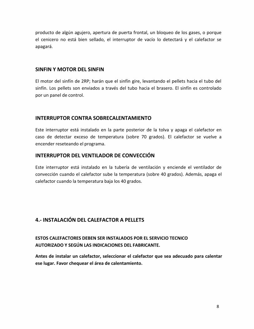
producto de algún agujero, apertura de puerta frontal, un bloqueo de los gases, o porqueel cenicero no está bien sellado, el interruptor de vacío lo detectará y el calefactor seapagará.
SINFIN Y MOTOR DEL SINFIN
El motor del sinfín de 2RP; harán que el sinfín gire, levantando el pellets hacia el tubo delsinfín. Los pellets son enviados a través del tubo hacia el brasero. El sinfín es controladopor un panel de control.
INTERRUPTOR CONTRA SOBRECALENTAMIENTO
Este interruptor está instalado en la parte posterior de la tolva y apaga el calefactor encaso de detectar exceso de temperatura (sobre 70 grados). El calefactor se vuelve aencender reseteando el programa.
INTERRUPTOR DEL VENTILADOR DE CONVECCIÓN
Este interruptor está instalado en la tubería de ventilación y enciende el ventilador deconvección cuando el calefactor sube la temperatura (sobre 40 grados). Además, apaga elcalefactor cuando la temperatura baja los 40 grados.
4.- INSTALACIÓN DEL CALEFACTOR A PELLETS
ESTOS CALEFACTORES DEBEN SER INSTALADOS POR EL SERVICIO TECNICOAUTORIZADO Y SEGÚN LAS INDICACIONES DEL FABRICANTE.
Antes de instalar un calefactor, seleccionar el calefactor que sea adecuado para calentarese lugar. Favor chequear el área de calentamiento.

9
DECISIÓN DE DÓNDE UBICAR SU CALEFACTOR A PELLETS
Si se instala esta unidad sobre un piso combustible (por ej. Linóleo, pisos de madera) sedebe colocar bajo el calefactor, una plancha no combustible de al menos 15 mm deespesor. La plancha debe tener una extensión como minimo el ancho y fondo delcalefactor, más 6” (153mm) desde el frente del aparato.
El espacio libre entre los muros y el aparato no debe ser menor de 50mm.
Arme el calefactor antes de su instalación según se muestra en las siguientes imágenes:
1. ELÉCTRICO
Esta unidad debe tener tierra.

10
El cordón debe tener tierra y conectarse a un enchufe de 220V, 50Hz (4.5Amps). Por favorcuidar de que el cordón no quede atrapado bajo el aparato y que esté alejado de cualquiersuperficie caliente o puntas o filos cortantes y debe quedar accesible. Si llega a dañarsepor cualquier razón, se debe solicitar a un experto que lo reemplace por una piezaoriginal.
2. INSTALACIÓN DE LA ENTRADA DE AIRE Y TUBERÍA DE VENTILACIÓN
Horizontal y Arriba,

10
Horizontal, (Pero no se recomienda cuando el sistema electrico estaapagado por que puede haber escape de humos mientras la estufa estaencendida)

11
Horizontal y arriba, a través del alero
12
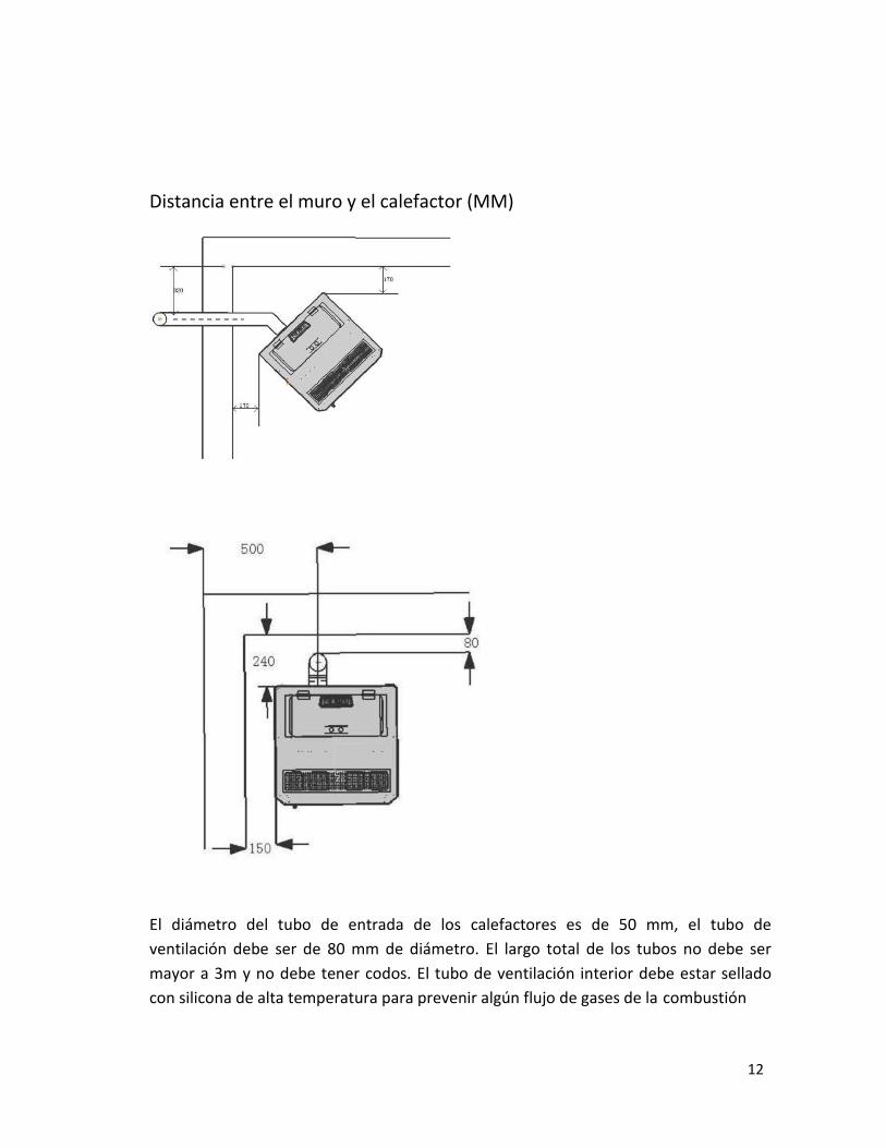
Distancia entre el muro y el calefactor (MM)
El diámetro del tubo de entrada de los calefactores es de 50 mm, el tubo deventilación debe ser de 80 mm de diámetro. El largo total de los tubos no debe sermayor a 3m y no debe tener codos. El tubo de ventilación interior debe estar selladocon silicona de alta temperatura para prevenir algún flujo de gases de la combustión

13
hacia la habitación. Las tuberías y terminaciones deben ser a prueba de agua y se debeevitar bloqueos, de lo contrario el calefactor no podrá trabajar adecuadamente.
Cuando la instalación está limitada por el espacio, o el requerimiento especial en unainstalación específica necesita más de 3 metros y agregar codos, los diámetros de latubería de entrada de aire y ventilación debe incrementar proporcionalmente paraadecuar la convección. Si no lo hace es posible que el funcionamiento del aparato sevea afectado considerablemente. Esta instalación debe ser realizada por personalexperto y autorizado SEC. Cuando el calefactor está funcionando normalmente, latemperatura en el tubo de ventilación puede alcanzar los 200°C, por lo tanto, no dejarelementos combustibles, ropa o muebles cerca del tubo. Para evitar quemaduras, notocar esta superficie.
Requerimientos de terminación de las tuberías.
(1) No ubicar los tubos hacia lugares cerrados como garajes, carpas, áticos, salas dejuegos, pasadizos, junto a la cerca, bajo la cochera, cobertizos, corredores, ocualquier otra ubicación que pudiera concentrar los gases de lacombustión.
(2) Las superficies de los tubos de ventilación pueden calentarse lo suficiente comopara provocar quemaduras al tacto. Se podría requerir un protector no combustible.
(3) Las terminales deben evacuar sobre la elevación de la entrada de aire. Serecomienda instalar al menos unos 152 cm de tubería vertical en el exterior,cuando el calefactor lleva tubería al muro. Esto creará un tiraje natural paraprevenir la posibilidad de que se produzcan olores o humos cuando el calefactor seapague o haya corte de energía y se evita exponer a las personas o arbustos a altastemperaturas.
(4) La distancia entre la parte posterior y el ángulo debe ser de un mínimo de 12”. Ladistancia entre el final del tubo y una vereda pública de ser de un mínimo de 213cm.
(5) Ubicar la terminal de ventilación al menos a 61 cm pies de cualquier materialcombustible, como arbustos, plantas, pasto, cercas, salientes de techos oedificaciones adyacentes.Para la ventilación de este calefactor se debe utilizar tubería para Pellet de tipo PLo L. El collarín para este calefactor debe ser de 3” de diámetro. Se debe utilizar unrevestimiento protector de pared o cielo antiflamas para pasar la tubería a travésde cielo raso combustible.El ventilador de combustión del calefactor presuriza y empuja os gases hacia eltubo de pellet. Todos los ensambles de la tubería deben estar atornillados con trestornillos y perfectamente sellados con silicona de alta temperatura.

14
La tubería debe ser sellada con silicona de alta temperatura y asegurada con trestornillos al collarín de salida de gases del calefactor.Mientras más largo sea el tubo y si usa o no codos, será entonces mayor laresistencia al flujo de salida de gases. Para tubería más larga que 15” o cuando seutiliza codos, se recomienda un tubo de 4 pulgadas
NO INSTALAR DAMPER O PORTEZUELA EN EL SISTEMA DE SALIDA DEGASES DE ESTE CALEFACTOR. NO CONECTAR ESTA UNIDAD A UNACHIMENEA DE OTRO APARATO.
ADVERTENCIA: no instalar el calefactor en las habitaciones en dondeduermen personas, ni en habitaciones aledañas o piezas sinventilación.
Para instalar, no se debe alterar la parte estructural del piso, muros ocierlos.
PROTECCIONES DEL SINFÍN.
Para asegurar que los componentes eléctricos no sean dañados debido al sinfín en elabastecimiento eléctrico se recomienda un protector de sinfín. Se debe usar sóloprotectores de buena calidad. Los protectores baratos no proveen la protección necesaria.
INSTALACIÓN DEL TERMOSTATO
Los calefactores vienen cableados de fábrica para operar manualmente. Ver operacióndel panel de control en la página siguiente. Se debe instalar un termostato de bajovoltaje.
PRECAUCIÓN: Por favor poner un sensor (T3) en la parte posterior del tubo deventilación. Este sensor detecta la temperatura en la habitación; no debe estarinfluenciado po ningún otro objeto caliente o frío. Seleccionar el lugar que usted considerael más adecuado para medir la temperatura de la habitación.
LA INSTALACIÓN DE ELEMENTOS DE SEGURIDAD, PRECAUCIÓN OREPARACIONES A ESTE ARTEFACTO, SÓLO DEBEN SER LLEVADOS A CABO

15
POR PERSONAL CALIFICADO Y AUTORIZADO SEC. NO INTENTE HACERLOUSTED MISMO.
RECURDE QUE LOS PROBLEMAS O MAL FUNCIONAMIENTO DERIVADOS DEUNA MALAMANIPULACIÓN NO ESTAN CUBIERTOS POR LA GARANTÍA.
Evite excederse en la alimentación de la pelletera. No alimente el calefactor con la mano.Nunca use gasolina, parafina, encendedores de carbón líquido o líquidos similares paraencender o como mecha para el fuego. Mantener todos estos líquidos lejos del calefactor,especialmente cuando esté en uso. Para su seguridad, no instalar u operar el calefactor sinhaber leido previamente el manual de instrucciones proveído por el fabricante.
Cualquier instalación u operación de este aparato que no se ciña estrictamente a loespecificado en este manual puede hacer que usted pierda la garantía o que ocurra algúndaño a las personas o al inmueble.
Debido a que puede alcanzar altas temperaturas, este calefactor debe instalarse fuera delas áreas de tráfico de personas y lejos de los muebles. Los niños y los adultos deben estaralerta de la temperatura que pueden alcanzar y mantenerse alejados para evitarquemaduras o incendios. Los niños pequeños deben estar permanentementesupervisados cuando están en el mismo espacio del calefactor. La ropa o cualquier otroelemento inflamable no debe ser ubicado cerca del calefactor. Cualquier elemento que sehaya quitado al calefactor para su mantenimiento o cambio, Debe ser reemplazado antesde volver a operar el calefactor.
No operar este aparato con el vidrio frontal removido, trizado o quebrado. El reemplazode los vidrios debe ser realizado por personal experto. El fabricante no se haceresponsable por daños ocasionados por mala manipulación, servicio o procedimientos deinstalación inadecuados, ya sea directo o indirecto de parte del usuario. El aparato debeser instalado de acuerdo con las normas locales.

16
5. OPERACIÓN
AL OPERAR ESTE APARATO SE DEBE CUMPLIR CON TODAS LAS NORMALOCALES EMANADAS DE LA SUPERINTENDENCIA DE ELECTRICIDAD YCOMBUSTIBLES SEC Y DEL MINISTERIO DEL MEDIO AMBIENTE.
1) PRIMER ENCENDIDOLa primera vez que se enciende, se comienza a “quemar la pintura” y el calefactorpuede emitir un desagradable olor. Favor de abrir puertas y ventanas por una ratopara eliminar el olor.Nota: Puede que la primera vez que use el calefactor sea necesario colocar unpoco de pellet de forma manual en el brasero conanticipación.Colocar pellet en la tova, enchufar. La luz de ENCENDIDO/APAGADO se enciende.Operar de acuerdo con las instrucciones en la sección 2 “Inicio y operación”.
Nota: Mantener el brasero y sus alrededores limpios. Limpiar antes de cadaencendido.
2) INICIO Y OPERACIÓNPor favor operar el calefactor según sigue (referirse a la figura Estructura delCalefactor y Control Eléctrico) Chequear la caja, la rejilla, el plato de cenizas yajustarlos en su posición correcta.

17
GUIA RAPIDA DE OPERACIÓN

18
ENCENDIDO /APAGADO
El encendido y apagado del calefactor se realiza mediante un tecla ENCENDIDO/APAGADO(on/off)).
Lo primero que indica al encender es un recordatorio de que debe realizar la limpieza.
Limpieza “Cleaning” se muestra en pantalla por 20 segundos, para que usted recuerdelimpiar el brasero
De la misma forma, presionar , luego en el período de apagado, se muestralosiguiente:
Después de que la temperatura del calefactor ha bajado de 40°C, finalmente se mostrarála palabra “Adiós”.

19
¡ATENCIÓN!!
Durante la fase de apagado y enfriado del intercambiador, normalmente no estápermitido encender el calefactor de nuevo, hasta que todo el proceso se haya completado.
Sin embargo, si necesita encenderla de nuevo, asegúrese de estar vigilando el procesohasta su “Estabilización”, después puede presionar el botón aparece la frase enfriando“cooling”.
Después de que el calefactor se enfríe bajo los 50 grados, el calefactor parte de nuevo,Limpieza, alimentación, encendido, estabilización.
------------------------------------------------------------------------------------------------------------------------
¿Cómo hacer que el calefactor pase directamente a estabilización durante las primerasvarias etapas, cuando el usuario piense que la llama está ok y el calefactor puede trabajaradecuadamente?
Presionar por tres segundos y luego volverá a estabilización directamente.

20
La llama no enciende inmediatamente al efectuar la maniobra de encendido, depende dela formalidad seleccionada. Se puede seleccionar dos formas: AUTOMÁTICA o MANUAL,para mayores detalles ver la sección apropiada.
La etapa de encendido, que tiene una duración de 5 a 15 minutos, es necesario para quela resistencia lleve el pellets a la temperatura de encendido, (depende del calefactor). Elprocedimiento de encendido se muestra en pantalla. Antes de iniciar el encendido, elcalefactor realiza la limpieza y las siguientes palabras se muestran enpantalla:
Primero:
Segundo
Tercero
Al iniciar la primera fase de encendido aparece el mensaje “ALIMENTACIÓN”. En esta fasese llevan a cabo las operaciones de verificación de chimenea y los pellets son cargados ensu vasija. En la fase sucesiva la pantalla muestra “Encendido” “Lighting”. En esta fasecomienza a alimentarse. Este estado se mantiene hasta cuando la temperatura no excedeel umbral planificado.

21
¡Atención!
Pueden pasar algunos minutos desde la aparición de los primeros indicios de humo, hastaque el pellet enciende.
La llama no enciende inmediatamente al efectuar la maniobra de encendido, depende dela formalidad seleccionada. SE puede seleccionar dos formas: AUTOMÁTICA o MANUAL,para mayores detalles ver la sección apropiada.
Cuando se termina la fase de encendido “Lighting”, pueden pasar algunos minutos para laestabilización de la llama. L apantalla mostrará el mensaje “ESTABILIZACIÓN” el cual seapaga luego de unos minutos que el calefactor comienza a trabajar.
Es posible apagar el calefactor en cada fase de funcionamiento. Se realiza presionando latecla “ON/OFF” ENCENDIDO/APAGADO por dos segundos.
¡ATENCIÓN!
Al apagar el calefactor, la llama continuará estando presente hasta que el combustible queestá en el brasero se termine. Esta fase utilizará los ventiladores en forma automática ytendrá una duración de 5-8 minutos.
Durante toda la fase de apagado, la pantalla mostrará “Switching Off” Apagando.
Aún si el calefactor se apaga o no, la pantalla mostrará la hora, la potencia y latemperatura fijada.
Nota: Durante el primer uso de un calefactor nuevo, es necesario poner un poco depellet a mano con anticipación.

22
Nota: Si el encendido no se produce, el control térmico apagará el calefactorautomáticamente. La pantalla mostrará E1 (Error de encendido). Para reiniciar, chequear
el calefactor como lo hace en forma regular, luego pulsar para limpiar la pantalla deE1. Siga el mismo proceso anterior para reencender.
VARIACIÓN DE LA LLAMA
Depende de lo que el usuario desee. Se puede ajustar la cantidad de combustible depoco a más, a través del botón de alimentación de combustible. Por ejemplo
Presionar la tecla para cambiar la cantidad de combustible, La pantallamuestrala selección.
POTENCIA MÍNIMA P4
POTENCIA BAJA P3
23
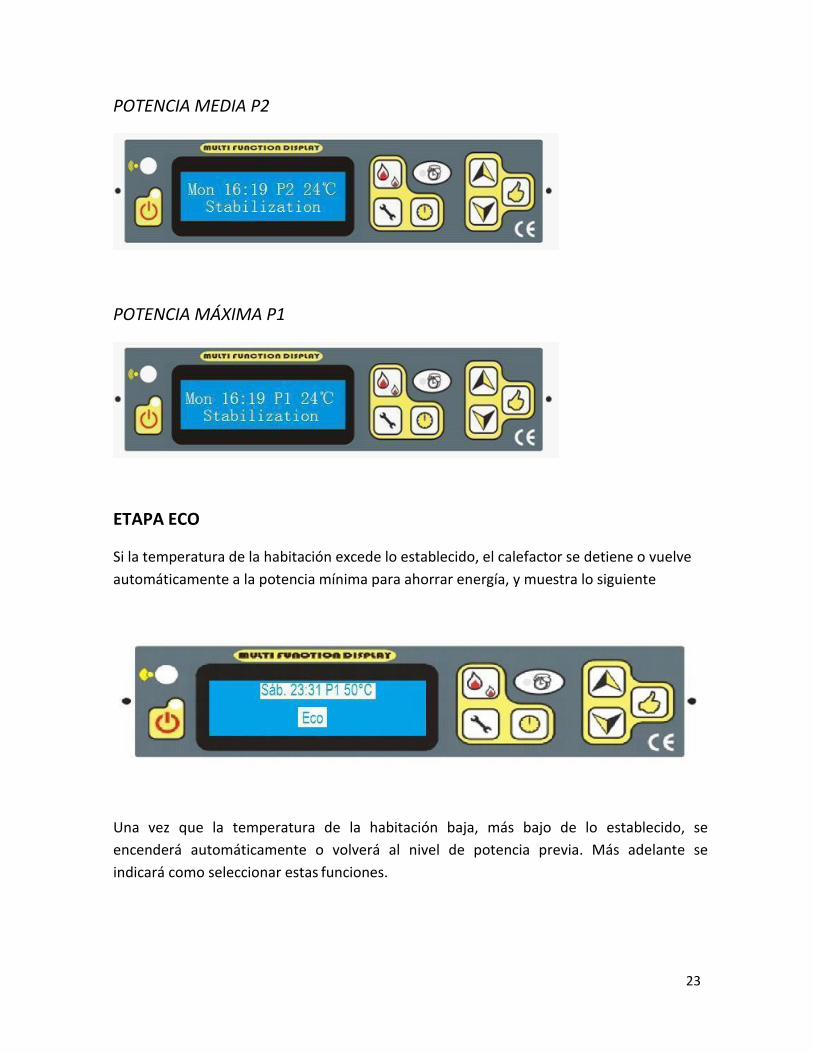
POTENCIA MEDIA P2
POTENCIA MÁXIMA P1
ETAPA ECO
Si la temperatura de la habitación excede lo establecido, el calefactor se detiene o vuelveautomáticamente a la potencia mínima para ahorrar energía, y muestra lo siguiente
Una vez que la temperatura de la habitación baja, más bajo de lo establecido, seencenderá automáticamente o volverá al nivel de potencia previa. Más adelante seindicará como seleccionar estas funciones.

24
SELECCIÓN AUTOMÁTICA Y MANUAL
Presionando las teclas la luz en estará ON/OFF Encendido/Apagado.
Si la luz está encendida significa que el programa se ha encendido automáticamente.
PARA FIJAR LA TEMPERATURA DESEADA
Presionar hasta lograr en la pantalla la temperatura deseada.
Como chequear la temperatura de la habitación, temperatura deevacuación (humo), seguridad (Protección)
La temperatura bajo la tolva………………………….Presionarelbotón
El número con “R” (room) es la temperatura de la habitación
El número con “S” (Smoke) es la temperatura del humo
El número con “P” (protección) es la temperatura para el sistema de seguridad
Por ejemplo
Significa que la habitación está a 13°C

25
6. CÓMO AJUSTAR CONFIGURACIÓN
GUIA RÁPIDA DE CONFIGURACIÓN
26
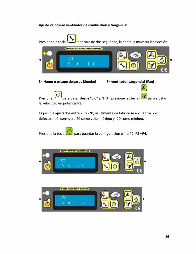
Ajuste velocidad ventilador de combustión y tangencial
Presionar la tecla por más de dos segundos, la pantalla muestra laselección
S= Humo o escape de gases (Smoke) F= ventilador tangencial (Fan)
Presionar para pasar desde “S 0” a “F 0”, presione las teclas para ajustarla velocidad en potencia P1.
Es posible ajustarlos entre 20 y -20, usualmente de fábrica se encuentra pordefecto en 0, considere 20 como valor máximo y -20 como mínimo.
Presione la tecla para guardar la configuración e ir a P2, P3 yP4.

27
Después de P4, esta P5, este dato está relacionado con la velocidad del ventiladorde extracción de humos durante la fase de "limpieza".
El rango de ajuste es también entre20 y -20.
Luego esta P6, este dato se relaciona con la velocidad del ventilador de extracciónde humos durante la fase de la alimentación, encendido y en algunos minutos dela etapa de estabilización.
El rango de ajuste es también 20--20

28
Usted puede seleccionar la semana o la hora presionando la tecla
Ajuste cantidad de pellet para encendido
Presionando la tecla , la pantalla muestra la selección
Usted verá 75*2 Seg., esto quiere decir que cada 150 Seg. caerá pellets al braceropara iniciar el encendido.
Este valor puede ser ajustado a través de lasteclas
Ajuste del Reloj
Presionar la tecla por más de dos segundos, la pantalla muestra laselección
Se puede elegir una semana a través de las teclas , para grabar presionar la
tecla y se moverá al siguiente estado.
La hora también puede seleccionarse con , para grabar presione lateclay se moverá al siguiente estado.

29
Ajuste de la limpieza
Manteniendo presionada la tecla usted puede ajustar el tiempo de limpiezadurante la operación.”Cada x minutos, hasta Y segundos” para limpiar el brasero
con la tecla por ejemplo cada 30 minutos, los últimos 15segundos.
Ajuste de programación o timer
La siguiente frase aparecerá en pantalla
Con esta función usted puede programar su calefactor para el funcionamiento deuna semana. Usted puede programar en encendido y apagado diario, por toda lasemana.
Presionando la tecla
Presionando la tecla para seleccionar horas, luego presionar paraseleccionar la hora de encedido y apagado.

30
En la línea superior el día en que se está programando y la horaEn la línea más debajo de la pantalla aparece la hora
La más baja significa Apagado, La más alta significa Encendido ytambiénaparece en la línea superior.
Ajuste del Lenguaje
Presionando la tecla aparecerán las siguientespalabras:
Con esta función usted puede seleccionar el lenguaje
Presionando la tecla para seleccionar el lenguaje. Incluye Inglés Japonés,Italiano y Español.

31
Ajuste del modo Eco
Presionando la tecla aparecerán las siguientespalabras:
Presionando la tecla para seleccionar el modo 1 o modo 2. El modo 2 es paravolver el calefactor a la potencia mínima, el modo 1 es para detener elcalefactor.
Resolución de problemas
Presionando la tecla aparecerán las siguientespalabras:
Presionando la tecla usted puede seleccionar Sí o No“Sí” Quiere volver a prefijado de fábrica“No” Quiere usar los datos que usted haseleccionado
Presionando la tecla El programaterminará.

32
¡ATENCIÓN!
Si en pantalla se muestra, por ej.:
Significa que la llama se apaga automáticamente durante la operación, cuando latemperatura de salida de gases está bajo 40-45 grados.
Tales como:
1.- No hay combustible en la tolva2.- El sin fin está dañado y no está alimentando al calefactor.
Significa que tiene falla en el encendido.
Tales como:1.- Hay clinkers (durezas) en el brasero2.- El brasero está mal puesto3.- El interruptor de testeo de temperatura de evacuación de gases, ubicado allado del ventilador de combustión, está dañado.4.- El encendedor está dañado.

33
Significa que ha habido terremoto durante el período de operación o la estufa se
ha dado vuelta. (Sólo para la versión japonesa)
Problema en el sensor de temperatura.Está desenchufado o dañado, o la temperatura del agua es demasiado alta (Estafunción es sólo para los calefactores a pellet con agua caliente)
Indica que puede haber problemas con el interruptor de vacío, por ej. Que unapuerta no esté bien cerrada, o el ventilador de combustión no está trabajando ohay una fuga en el calefactor o hay algún bloqueo en la tubería de extracción degases, etc.

34
Significa que el sensor de alta temperatura, que está ubicado bajo la tolva, tieneproblemas, como:1.- El interruptor está dañado2.- La temperatura es demasiado alta y el calefactor no está funcionandoadecuadamente.
Ha habido un corte de energía eléctrica.
Indica que debe limpiar el calefactor.
Para chequear que todo esté bien, presionar para borrar el códigodeerror.

35
¡ATENCIÓN!
Si al encender el calefactor le aparecen palabras como:
Significa que el sensor de temperatura 1 (sensor de temperatura de gases deevacuación) está en corto circuito.
Significa que el sensor de temperatura 1, está en circuito abierto
Significa que el sensor de temperatura 2 bajo la tova, está en corto circuito.
Significa que el sensor de temperatura 2 está en circuito abierto

36
Significa que el sensor de temperatura 3 (sensor para testear la temperatura delambiente y que está ubicado en la parte posterior del panel) está en corto circuito.
Significa que el sensor de temperatura 3 está en corto circuito.
CONTROL REMOTO

37
7. SEGURIDAD
(1) Si el calefactor comienza a funcionar fuera de norma o una temperatura insegura,el calefactor se apagará.
(2) El calefactor se apagará cuando el termostato (de la tolva) T2≥70°C(3) Cuando el tubo de ventilación se bloquee, la luz indicadora de ventilación se
encenderá y el calefactor se apagará. Usted debe llamar al servicio técnicoautorizado.
COMBUSTIBLE: este calefactor a pellet ha sido diseñado y aprobado sólo para serutilizado con combustible Pellet con sobre 3% de contenido de cenizas. Uncombustible sucio afectará el funcionamiento y desempeño de la unidad, lo cual noestá cubierto por la garantía.
RECOMENDACIONES Y ADVERTENCIAS DE SEGURIDAD
PRECAUCION: Es importante seleccionar y usar sólo pellets seco y libre de suciedad ocualquier impureza, como contenidos de sal. Un combustible sucio afectaránegativamente el funcionamiento y desempeño del calefactor y podría provocar lapérdida de la garantía.
PRECAUCIÓN: NO CONECTAR A NINGUN CONDUCTO O SISTEMA DEDISTRIBUCIÓN DE AIRE. NO QUEMAR BASURA, FLUIDOS INFLAMABLESCOMO GASOLINA, PARAFINA O ACEITE DE MOTOR.
Cuando la unidad esté en operación, mantener a los niños, ropas o muebles alejados. Elcontacto con algunas partes de este aparato cuando está en uso, pueden causarquemaduras.
HOLLÍN: Operar este calefactor con aire insuficiente para la combustión podría resultar enla formación de hollín, el cual quedará depositado en el vidrio, el intercambiador de calor,el sistema de evacuación de gases de la combustión, y habrá manchas de hollín por toda lacasa. Esta es una situación peligrosa e ineficiente. Chequear frecuentemente el calefactory remover el polvo y durezas (clinkers) para asegurar una buena combustión. Si esnecesario, llamar al servicio técnico autorizado para ajustar el ventilador o cualquier otrapieza que necesite ajuste.

38
8. LIMPIEZA
Puede haber algo de ceniza volátil y pequeñas cantidades de creosota adherida en laevacuación de gases. Esto puede variar según el tipo de combustible y el contenido decenizas que tenga. Se aconseja inspeccionar el sistema de evacuación de gases de lacombustión al menos dos veces al año o cada dos toneladas de pellets.
Precaución: Durante el proceso de quemador se debe mantener la puerta del aparatocerrada y sellada para evitar que la ceniza vuele. La caja de llama debe estarpermanentemente cerrada mientras el aparato esté en funcionamiento.
Características del quemado: la llama amarillo brillante, el pellet encendido con pequeñossaltitos. El pellet no se apila. Si la llama se torna algo oscura y floja, aparece el humo desdeel terminal de ventilación, se debe apurar un poco el ventilador para agregar más aire.
La tubería de ventilación y la tubería de entrada de aire se debe revisar en forma periódicapara evitar bloqueos.
Este aparato está diseñado para trabajar con clima frío. No operar este aparato en climascalurosos.
No realizar ninguna modificación no autorizada a este aparato.
Las piezas y partes sólo pueden ser reemplazadas por personal autorizado por el fabricante.
9. MANTENIMIENTO
Desenchufar y dejar que el calefactor se enfríe antes de llevar a cabo cualquiermantenimiento o limpieza. Alguna marcas de pellets producen mayor cantidad de cenizasy producen más clinkers (durezas) que otras. Por lo tanto, es indispensable que usted llevea cabo los procedimientos de limpieza lo más a menudo posible, dependiendo de lacalidad del pellets que esté utilizando. No realizar una limpieza regular a este aparato haráque tenga un desempeño pobre y comenzará a bloquearse o dejará de funcionar. Uncalefactor sucio por falta de mantenimiento regular, no está cubierto por lagarantía.

39
LIMPIEZA DEL BRASERO
El ventilador de combustión se enciende a alta velocidad una vez cada hora para soplar losproductos de a combustión fuera del brasero. Sin embargo, el brasero debe ser limpiadomás detenidamente después de quemar 10 sacos de pellet. El brasero tiene una cantidadde agujeros en el fondo y a los lados que proveen aire para combustionar el pellet. Lastemperaturas extremas en el brasero pueden provocar que las impurezas del pelletformen cenizar y clinkers (durezas).
Cuando el calefactor esta frio, abra la puerta frontal y levante el brasero de fierro. Rasparel fondo y los lados del brasero con un destornillador para remover toda la ceniza yclinkers de esta superficie.
Además, también limpiar las barras del encendedor cuidadosamente. Las barras estánhechas de ceramicas y pueden romperse fácilmente si son manipuladas con algúnelemento demasiado duro, o caen al piso. Asegurarse que los agujeros en el fondo delbrasero estén abiertos. Colocar el brasero en el sitio del cual fue removido. Asegurarseque la parte alta del brasero rota hacia el frente del calefactor. Presionar el brasero paraajustarlo en su superficie. No utilizar ningún otro elemento como brasero en estecalefactor.
LIMPIEZA DEL VIDRIO
Precaución: no abrir la puerta frontal cuando el calefactor esté caliente. Limpiar el vidrioutilizando un paño suave o toalla de papel. Para limpiar el vidrio, también se puede utilizarun paño humedo.
LIMPIEZA Y REMOCIÓN DEL CENICERO
Precaución: no remover el cenicero mientras el calefactor esté caliente. Tirar el ceniceropara sacarlo del calefactor.
Precaución: para eliminar las cenizas se deben colocar en un contenedor de metal con unatapa muy firme. El contenedor cerrado debe ser ubicado en un piso no combustible o enla tierra lejos de cualquier material combustible hasta su eliminación final. Reinstalar elcenicero insertándolo en su lugar en el calefactor y moviéndolo hacia la izquierda yderecha para ubicarlo en su lugar. Si el cenicero no se ajusta bien al calefactor el panel decontrol detectará una fuga y apagará el calefactor.
40
LIMPIEZA DEL VENTILADOR DE COMBUSTIÓN
Para limpiar el ventilador de combustión, remover los cuatro tornillos etiquetados con unaA en el dibujo hacia la derecha con una llave inglesa de 11/32”. Después de remover estostornillos el motor junto con el ventilador pueden ser extraídos de su lugar. Las hojas delventilador y el lugar en el que va ubicado pueden ser aspirados una vez que se saque elmotor. Al reinstalar el motor, puede que se necesite un nuevo burlete entre el motor y ellugar en que va ubicado el ventilador. Para completar la reinstalación vuelva a poner elmotor al lado del ventilador y reinstale los seis tornillos. Asegurarse de que el cable verdecon tierra del motor quede bien ubicado bajo uno de los tornillos.
LIMPIEZA DE LAS VÍAS DE EVACUACIÓN DE GASES DE LA COMBUSTIÓN
La limpieza de las vías de evacuación debería realizarse al menos una vez al año. Quemarpellets con mucha ceniza puede requerir que se haga esta limpieza más a menudo.Limpiar las vías sólo cuando el calefactor y las cenizas están frías. Aspirar las cenizascalientes podría hacer que se iniciara un fuego. En cada lado del calefactor hay doscubiertas de accesos ( ver letra B y letra C en el dibujo a la derecha) que pueden serremovidos desatornillando los dos tornillos allen 5/32”. Insertar un cepillo de limpieza enlas aberturas para aflojar la ceniza adherida y usar una aspiradora para aspirar la cenizasuelta. Reinstalar las cubiertas cuando la limpieza esté completa. Hay dos agujeros más deacceso ubicados detrás del cenicero. Remover el cenicero (ver la página previa) y soltar losdos tornillos allen de 5/32” que se muestran con la letra D en el dibujo más abajo. Rotarlas cubiertas sobre los agujeros de acceso y utilizar un cepillo y una aspiradora paralimpiar las cenizas. Rotar las cubiertas sobre los agujeros nuevamente yatornillar.
LIMPIEZA DEL VENTILADOR DE CONVECCIÓN
Para limpiar el ventilador de convección desenchufar el calefactor. Remover los paneleslaterales y posteriores (para todos los modelos) (y la cubierta frontal posterior para NB-PI,NB-PS, NB-P01, NB-PE09). Se puede usar una aspiradora para remover cualquieracumulación de polvo de las hojas del ventilador, o dentro de los ductos. Se debe tenercuidado de no dañar las hojas del ventilador durante la limpieza.

41
LIMPIEZA DEL TUBO DE VENTILACIÓN
Hoyín y ceniza volatil: formación y necesidad de remoción
Los productos de la combustión contienen pequeñas particulas de ceniza volatil que sequeda adherida al sistema de ventilación y restringe el flujo de los gases de la combustión.La combustión incompleta por ejemplo durante la etapa de encendido o apagado, uoperación incorrecta del calefactor provocará que haya formación de hoyín el cual seadhiere al sistema de ventilación. El sistema de ventilación de gases de la combustióndebe ser inspeccionado al menos una vez al año para determinar si es necesario realizaruna limpieza. Se necesita barrer el tubo.
CALENDARIO DE LIMPIEZA SEGÚN CANTIDAD DE SACOS DE PELLET QUEMADOS
Brasero=1 bolsa
Cenicero= 25 bolsas
Ventilador de evacuación de gases= 100 bolsas
Soplador = 100 bolsas
NOTA: el calendario de limpieza puede variar según la calidad del pellet usado. Un pelletcon demasiada ceniza requerirá limpieza más frecuente.
10. SOLUCIÓN DEPROBLEMAS
El panel de control del calefactor tiene sensores para examinar los problemas cuando elsensor detecta una temperatura de trabajo anormal (bajo los 30 grados celcius) o latemperatura está sobre 70 grados celcius el interruptor de autocontrol de temperaturafuncionará.
Cuando la temperatura está bajo los 30 grados Celcius el sistema de control de seguridadapagará el calefactor automáticamente. Cuando el otro sensor fijado en la tolva detectaque la temperatura está sobre 70 grados Celcius el calefactor de apagará.

42
Los problemas generales y sus posibles razones son los siguientes:
Problemas Razones Soluciones1. La luz de inicio o lapantalla no se enciendencuando el calefactor estáencendido.
No hay electricidad enel calefactor o en elpanel de control.
Chequear el sistema eléctrico y elcableado.
El fusible está dañado. Reemplazar el fusible.
2. El ventilador no trabajaluego de presionar elbotón de encendido.
Es normal.Se iniciaráautomáticamentecuando la temperaturasuba de los 30 gradosen el tubo deventilación.
Favor esperar
Si después de laestabilización no trabajadebe haber algo mal.
No llega electricidad alcalefactor o al panel decontrol.
Está desenchufado .
Chequear el sistema eléctrico y elcableado
Enchufar
El sensor detemperatura baja estádañado .
Reemplazarlo
3. Si después de 20 segundos de iniciado no comienza la alimentaciónHay 3 etapas del proceso de alimentación .
i) durante varios minutos la alimentación es constante, La palabra“alimentación”aparece en la pantalla LCD.
ii) Si los siguientes minutos la luz de alimentación se apaga: la palabra “luz” semuestra en la pantalla
En la última etapa el calefactor se alimenta cada cierta cantidad de segundos después delas dos etapas previas.
A. Si no se alimenta en La unidad de Chequear el sinfin y eliminar ella primera etapa( durante los primeros
alimentación estábloqueada .
bloqueo.
minutos) Hay un problema enla conexión entre elmotor y el sinfín.
Chequear el tornillo de ajusteentre el sinfín y el motor yajustarlo para evitar que elsinfín esté saltando.
No hay combustibleen la tolva.
Llenar la tolva con combustible.
B. Si no se alimenta enla segunda etapa
Es normal Por favor ser paciente

43
C. Respecto de laúltima etapa
La unidad dealimentación estábloqueada
Chequear que el sinfín no estébloqueado
Hay un problema decoenxión entre elsin fin y el motor
Chequear el tornillo de ajusteentre el sinfín y el motor yajustarlo para evitar que elsinfín esté saltando.
No hay combustibleen la tolva
Llenar la tova de combustible
4. No se alimentaadecuadamenteA) Demasiadopellet que nos epuede quemar atiempo
El nivel dealiemntación estádemasiado alto
Ajustar la velocidad delventilador de combustión o lavelocidad del alimentador.
B) El fuego se pagaporque hay pocopellet
El nivel dealimentación esdemasiado bajo
Ajustar la velocidad delventilador de combustión o lavelocidad del alimentador.
5.- Después delencendido el aparatose apaga 15 minutosmás tarde
La unidad de pelletestá vacía o tienemuy poco.El interruptor detemperatura de30°C está dañado olos cables estánsueltosEl interruptor depresión estádañado
Chequear la unidad dealimentació y reiniciarChequear los cables deconexiónCambiar el interruptor detemperatura de 30°CCambiar el interruptor depresión
5. Fuego anaranjadoy flojo, pelletsamontonado,carbón en el vidrio
Falta de ventilaciónpara encender
Limpiar los bloqueosdel ventilador
Chequear el burletede puertas yventanas
Chequear el tubo deingreso de aire y eltubo de ventilaciónpara eliminarbloqueos ylimpiarlo.
Si los tubos sondemasiado largocomo para afectar la

44
combustión, sedebe cambiar lostubos por unos demayor diámetro.
Ajustar el ventiladorde combustión
Llamar al serviciotécnicoespecializado
El fuego se va y el La tolva está vacía Poner combustible en la tolvaaparato se paga No hay combustible Bajar la velocidad delautomáticamente Hay poco ventilador de combustión
combustible Enfriar el calefactor al menosEl interruptor de una hora y poner a funcionartemperatura baja de nuevo o cambiar el(30°C) está dañado. interruptor de temperatura
baja (30°C)En fase “ECO” es normal, unavez que la temperatura seajuste, se encenderá de nuevo.
El ventilador aún El interruptor de Cambiar el interruptorfunciona luego que el temperatura bajacalefactor se ha (30°C) está dañadoenfriado y ha dejadode alimentar elcombustible9.- No hay suficiente La tubería está Cerrar el calefactoraire caliente bloqueada Limpiar la tubería
La puerta está Cerrar la puerta y desenchufarabierta Chequear y repararHay alguna fuga Ajustar el ventilador de
combustión para dar máspresión al calefactor.
45
OPERACIÓN DEL GENERADOR ELÉCTRICO
Este calefactor puede recibir energía de un generador eléctrico. Sin embargo, debe tenercuidado que el geenrador tenga compatibilidad con el calefactor. Mientras mejor sea lacalidad del generador, mayor sera la posibilidad de que sea compatible con la estufa.
11. GARANTÍA
La garantía legal de este aparato cubre defectos de fabricación. Si el usuario sigue lasinstrucciones de este manual, se garantiza un funcionamiento normal.
Cualquier daño producido al calefactor por efectos de pellets de mala calidad, o por malamanipulación, no está cubierto por la garantía.
El mal funcionamiento por falta de limpieza de este aparato, no está cubierto por lagarantía.
El mal funcionamiento producto de una instalación inadecuada, no esta cubierto por lagarantía.
Los vidrios quebrados no están cubiertos por la garantía.
Las piezas dañadas por mala manipulación, no están cubiertas por la garantía.
1.- La instalacion y puesta en marcha debe ser llevada a cabo por nuestro servicio tecnicoSERVICRUZque cuenta con personal capacitado.
2.-Usted debe solicitar una mantenimiento a nuestro servicio técnico autorizadoSERVICRUZ, al menos una vez al año.

46
12. PLANO ELÉCTRICO

47

1
SALAMDRA À PELLET AUTÓNOMA(POR FAVOR MANTENHA ESTAS INSTRUÇÕES PARA FUTURAS CONSULTAS)
Calor para toda a vida
* Por favor, leia todo este manual antes de instalar e utilizar o
equipamento Salamandra A Pellets com caldeira.
O não cumprimento destas instruções pode resultar em danos
materiais, lesões corporais, ou até mesmo a morte.
* Guarde estas instruções!INSTALADOR: Este manual DEVE PERMANECER COM O APARELHO!

2
Índice de conteúdos1. Requisitos de combustível-----------------------------------------3
2. Características do fogão-------------------------------------------- 4
3. Instruções de estrutura---------------------------------------------- 6
4. Instalação da Salamandra------------------------------------------ 8
5. Operações----------------------------------------------------------- 12
6. Limpeza e manutenção------------------------------------------- 26
7. Resolução de problemas------------------------------------------ 30
8. Garantia------------------------------------------------------------- 35
9. Plano Electrónico-------------------------------------------------- 37
3
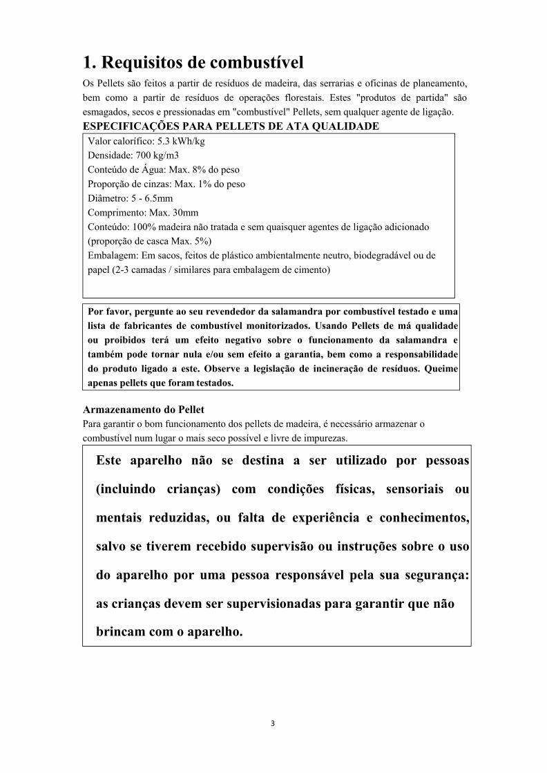
Por favor, pergunte ao seu revendedor da salamandra por combustível testado e umalista de fabricantes de combustível monitorizados. Usando Pellets de má qualidadeou proibidos terá um efeito negativo sobre o funcionamento da salamandra etambém pode tornar nula e/ou sem efeito a garantia, bem como a responsabilidadedo produto ligado a este. Observe a legislação de incineração de resíduos. Queimeapenas pellets que foram testados.
1. Requisitos de combustívelOs Pellets são feitos a partir de resíduos de madeira, das serrarias e oficinas de planeamento,bem como a partir de resíduos de operações florestais. Estes "produtos de partida" sãoesmagados, secos e pressionadas em "combustível" Pellets, sem qualquer agente de ligação.ESPECIFICAÇÕES PARA PELLETS DE ATA QUALIDADEValor calorífico: 5.3 kWh/kgDensidade: 700 kg/m3Conteúdo de Água: Max. 8% do pesoProporção de cinzas: Max. 1% do pesoDiâmetro: 5 - 6.5mmComprimento: Max. 30mmConteúdo: 100% madeira não tratada e sem quaisquer agentes de ligação adicionado(proporção de casca Max. 5%)Embalagem: Em sacos, feitos de plástico ambientalmente neutro, biodegradável ou depapel (2-3 camadas / similares para embalagem de cimento)
Armazenamento do PelletPara garantir o bom funcionamento dos pellets de madeira, é necessário armazenar ocombustível num lugar o mais seco possível e livre de impurezas.
Este aparelho não se destina a ser utilizado por pessoas
(incluindo crianças) com condições físicas, sensoriais ou
mentais reduzidas, ou falta de experiência e conhecimentos,
salvo se tiverem recebido supervisão ou instruções sobre o uso
do aparelho por uma pessoa responsável pela sua segurança:
as crianças devem ser supervisionadas para garantir que não
brincam com o aparelho.
4
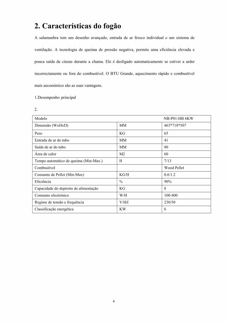
2. Características do fogãoA salamanbra tem um desenho avançado, entrada de ar fresco individual e um sistema de
ventilação. A tecnologia de queima de pressão negativa, permite uma eficiência elevada e
pouca saída de cinzas durante a chama. Ele é desligado automaticamente se estiver a arder
incorrectamente ou fora do combustível. O BTU Grande, aquecimento rápido e combustível
mais aeconómico são as suas vantagens.
1.Desempenho principal
2.
Modelo NB-P01-HB 6KW
Dimensão (WxHxD) MM 463*718*507
Peso KG 65
Entrada de ar do tubo MM 41
Saída de ar do tubo MM 80
Área de calor M2 60
Tempo automático de queima (Min-Max.) H 7/13
Combustível Wood Pellet
Consumo de Pellet (Min-Max) KG/H 0.6/1.2
Eficiência % 90%
Capacidade do depósito de alimentação KG 8
Consumo electrónico W/H 100-400
Regime de tensão e frequência V/HZ 230/50
Classificação energética KW 6

5
Modelo NB-P01-HB 8KW
Dimensão (WxHxD) MM 463*790*507
Peso KG 70
Entrada de ar do tubo MM 41
Saída de ar do tubo MM 80
Área de calor M2 70
Tempo automático de queima (Min-Max.) H 5/10
Combustível Wood Pellet
Consumo de Pellet (Min-Max) KG/H 0.8/1.6
Eficiência % 90%
Capacidade do depósito de alimentação KG 8
Consumo electrónico W/H 100-400
Regime de tensão e frequência V/HZ 230/50
Classificação energética KW 8
Modelo NB-P01-HB 10KW
Dimensão (WxHxD) MM 458*908*502
Peso KG 80
Entrada de ar do tubo MM 50
Saída de ar do tubo MM 80
Área de calor M2 90
Tempo automático de queima (Min-Max.) H 8/19
Combustível Wood Pellet
Consumo de Pellet (Min-Max) KG/H 0.8/2.0
Eficiência % 90%
Capacidade do depósito de alimentação KG 15
Consumo electrónico W/H 100-400
Regime de tensão e frequência V/HZ 230/50
Classificação energética KW 10
6
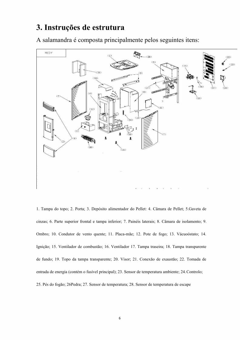
3. Instruções de estruturaA salamandra é composta principalmente pelos seguintes itens:
1. Tampa do topo; 2. Porta; 3. Depósito alimentador do Pellet: 4. Câmara de Pellet; 5.Gaveta de
cinzas; 6. Parte superior frontal e tampa inferior; 7. Painéis laterais; 8. Câmara de isolamento; 9.
Ombro; 10. Condutor de vento quente; 11. Placa-mãe; 12. Pote de fogo; 13. Vácuoóstato; 14.
Ignição; 15. Ventilador de combustão; 16. Ventilador 17. Tampa traseira; 18. Tampa transparente
de fundo; 19. Topo da tampa transparente; 20. Visor; 21. Conexão de exaustão; 22. Tomada de
entrada de energia (contém o fusível principal); 23. Sensor de temperatura ambiente; 24.Controlo;
25. Pés do fogão; 26Pedra; 27. Sensor de temperatura; 28. Sensor de temperatura de escape
7
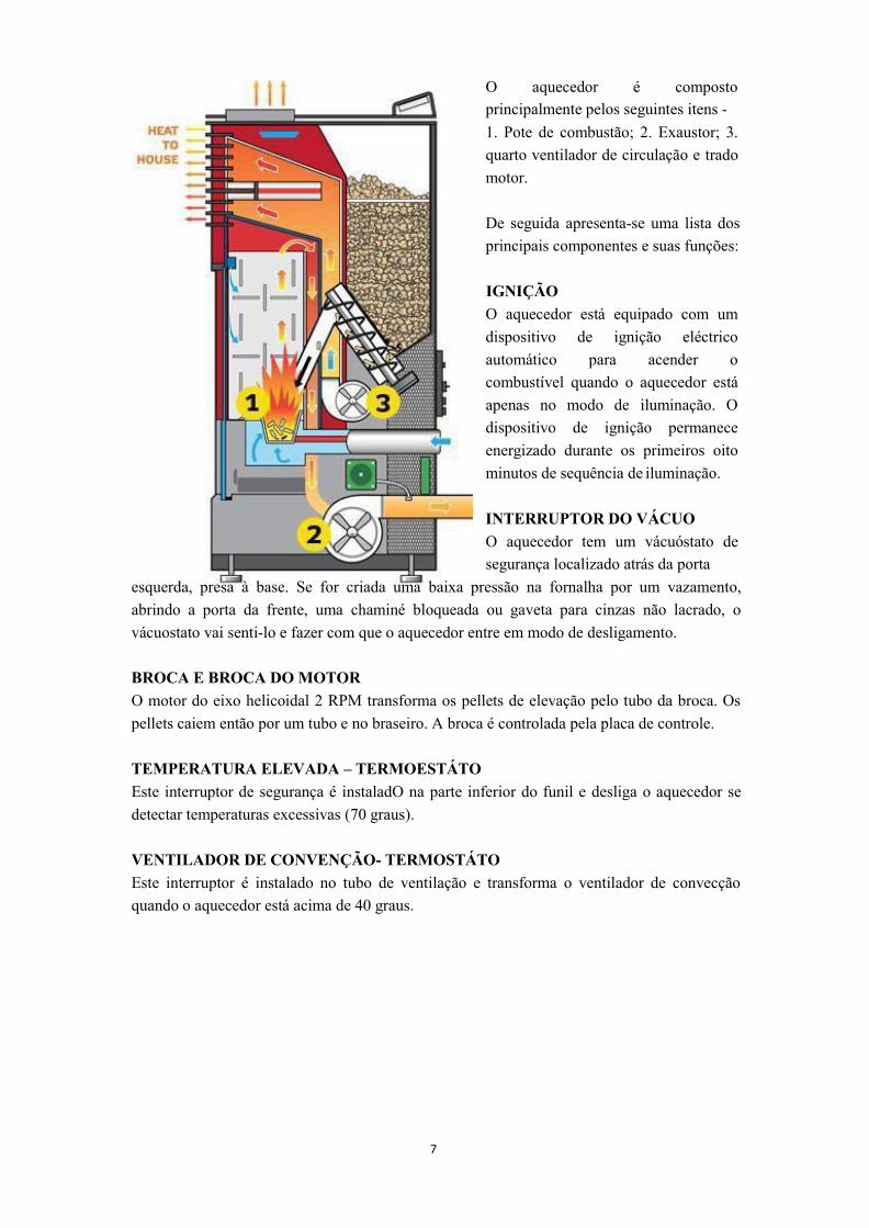
O aquecedor é compostoprincipalmente pelos seguintes itens -1. Pote de combustão; 2. Exaustor; 3.quarto ventilador de circulação e tradomotor.
De seguida apresenta-se uma lista dosprincipais componentes e suas funções:
IGNIÇÃOO aquecedor está equipado com umdispositivo de ignição eléctricoautomático para acender ocombustível quando o aquecedor estáapenas no modo de iluminação. Odispositivo de ignição permaneceenergizado durante os primeiros oitominutos de sequência de iluminação.
INTERRUPTOR DO VÁCUOO aquecedor tem um vácuóstato desegurança localizado atrás da porta
esquerda, presa à base. Se for criada uma baixa pressão na fornalha por um vazamento,abrindo a porta da frente, uma chaminé bloqueada ou gaveta para cinzas não lacrado, ovácuostato vai senti-lo e fazer com que o aquecedor entre em modo de desligamento.
BROCA E BROCA DOMOTORO motor do eixo helicoidal 2 RPM transforma os pellets de elevação pelo tubo da broca. Ospellets caiem então por um tubo e no braseiro. A broca é controlada pela placa de controle.
TEMPERATURA ELEVADA – TERMOESTÁTOEste interruptor de segurança é instaladO na parte inferior do funil e desliga o aquecedor sedetectar temperaturas excessivas (70 graus).
VENTILADOR DE CONVENÇÃO- TERMOSTÁTOEste interruptor é instalado no tubo de ventilação e transforma o ventilador de convecçãoquando o aquecedor está acima de 40 graus.

8
Apenas o pessoal técnico autorizado deve realizar o trabalho de montagem.
4. Instalação da SalamandraTODAS AS LEGISLAÇÕES E NORMAS LOCAIS, REGIONAIS E
EUROPEIAS, DEVEM SER RESPEITADAS AQUANDO A
INSTALAÇÃO DO APARELHO.
Antes de instalar a salamdra num quarto, seleccione o melhor fogão
para ser possível aquecer o quarto. Por favor verifique a área de
aquecimento dos FOGÕES no capítulo CARACTERÍSTICAS DO
FOGÃO.
INFORMAÇÕES GERAISA estufa deve ser ligada a uma chaminé aprovada para combustíveis sólidos. A chaminé temde ter um diâmetro de pelo menos 80 mm.O sistema de combustão é baseado em pressão negativa na câmara de combustão e umaligeira sobrepressão na saída de gás de combustão. Portanto, é importante que a ligação dogás de combustão seja montado correctamente e sejahermético.
Além disso, deve garantir que o tubo de combustão não projecta para a secção transversallivre da chaminé.
Garanta que as rotas de saída para a chaminé não são muito longos.Evite também muitas mudanças de direcção para o fluxo de gás para a chaminé. (por exemplo,
NOTA: Por favor, siga as normas de construção regional válidas. Contacte o seulimpador de chaminés mestre para obter informações sobre isso.
Utilizar apenas materiais de vedação resistentes ao calor, bem como as bandas devedação relevantes, silicone resistente ao calor e de lã mineral.
COMPLETE O FOGÃO ANTES DA INSTALAÇÃO

9
muitos cantos e curvas).Onde não poder conectar-se directamente à chaminé, se possível use uma peça de ligaçãocom a abertura de limpeza.Para a máxima eficiência por favor use o tipo de conector que recomendamos.
FAZENDO A CONEXÃO DA CHAMINÉ
Horizontal (Mas não é recomendado, pois quando o poder
electrónico estiver desligado, o fumo pode sair se o fogão
estiver ligado)
10
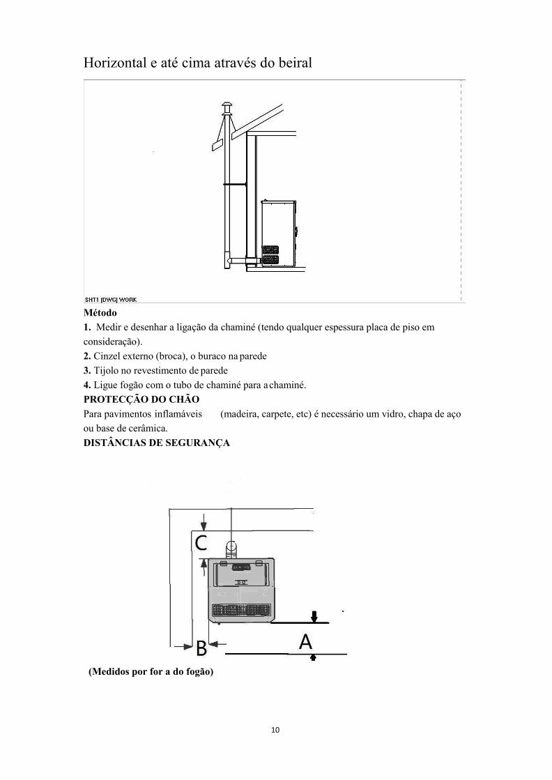
Horizontal e até cima através do beiral
Método1. Medir e desenhar a ligação da chaminé (tendo qualquer espessura placa de piso emconsideração).2. Cinzel externo (broca), o buraco na parede3. Tijolo no revestimento de parede4. Ligue fogão com o tubo de chaminé para achaminé.PROTECÇÃO DO CHÃOPara pavimentos inflamáveis (madeira, carpete, etc) é necessário um vidro, chapa de açoou base de cerâmica.DISTÂNCIAS DE SEGURANÇA
(Medidos por for a do fogão)

11
De objetos não-combustíveisA > 400 mm B > 100 mm C > 100mmDe objectos inflamáveis e paredes submetidas à carga para em concreto armadoA > 800 mm B > 200 mm C > 200mm
CONEXÃO ELÉCTRICAO fogão é fornecido com um atraso de aprox. 2 m de comprimento de ligação do cabo com atomada. O cabo deve ser ligado a uma alimentação eléctrica de 230V 50 Hz. O consumomédio de energia eléctrica é de aproximadamente 100 watts durante o aquecimento. Duranteo processo de ignição automática (duração de 10 minutos) aprox. 350 watts. O cabo deligação deve ser colocado de forma a que qualquer contacto com superfícies quentes ouexternos no fogão sejam evitadas.COMBUSTÃO DE ARCada procedimento de combustão requer oxigénio ou ar. Em geral, esse ar de combustão, éremovido a partir da sala de fornos individuais O ar tomado a partir da sala devem serrestabelecidos. Nas casas modernas, com janelas e portas de encaixe muito apertadassignificam que flui muito pouco ar. Esta situação torna-se problemática devido à ventilaçãoadicional na casa (por exemplo, na cozinha ou WC).A aspiração de ar de combustão é realizada através do soprador de gás de combustão. Osruídos resultantes do ar de combustão e de aspiração são ruídos normais de funcionamentoque pode ocorrer em volumes que variam de acordo com o projecto de chaminé, o nível desaída ou uma calha de combustão suja – e não um motivo dereclamação!Alimentação de ar externa● Aço, HT ou tubos de alumínio flexíveis devem ser usados.● Diâmetro minimo de 5 cm / 2 polegadas.● Para conexão maior o diâmetro deve ser aumentado para aprox. 10 centímetros apósaprox. 1 m.● O tubo não deve ser superior a aprox. 4m no total, para garantir a alimentação de aradequada e não ter muitas curvas.● Caso a ligação leve para o ar livre, deve terminar um eixo vertical de 90° do cotovelopara baixo ou com um guarda devento.Se uma ou mais destas condições não for aplicável, resultará em combutões pobres e iráocorrer em estufa, bem como o ar sob pressão no apartamento.
Recomendamos que uma grade de ventilação seja instalada numa janela perto do fogão para aventilação permanente. Além disso, é possível extrair o ar de combustão directamente doexterior ou de um outro quarto que é bem ventilado (por exemplo, a adega).Por favor observe:A salamandra funciona independente do ar ambiente. Pressões negativas na sala de set-up nãosão permitidas. Portanto, o uso de um dispositivo de segurança (por exemplo, controlador depressão diferencial), em combinação com instalações de ar do quarto (por exemplo, sistemade ventilação, exaustão extração etc) é estipulado.

12
Nota: Ao executar o primeiro tempo, a tinta pode ir saindo. Então, algum cheiro
desagradável pode sair. Por favor, abra a janela e porta para ventilar o cheiro.
Nota: Na primeira vez que utilizar o fogão, é necessário colocar um punhado de
aglomerados de madeira para a panela do fogo antes da mão.
Nota: Mantenha a panela do fogo e seu baixo limpo cada vez que iniciar o fogão!
5. OperaçõesTODAS AS LEGISLAÇÕES E NORMAS LOCAIS, NACIONAIS E
EUROPEIAS DEVEM ESTAR RESPEITADAS AQUANDO A
INSTALAÇÃO DO EQUIPAMENTO.
Atenção: quando o fogão estiver operacional, não toque na parte da
frente. Estará muito quente!
Coloque pellets de madeira para dentro do depósito e.ligue o aparelho. Então Light On / Off e o
aparelho ilumina (Significa que o poder está ligado). Operar como as instruções na secção
"começar a operação"
Guias de Operação
Por favor, utilize o fogão da seguinte forma (veja a estrutura do fogão e as figuras do controlo
eléctrico): verifique a caixa, a grelha de barras de pellet, a caneta de cinzas e só depois ajuste na
posição correcta.

13
Iniciar / Parar
Auto / Manual
Nível de chama
Temperatura / Termostato
1. Instruções de Operação – Guia Rápido de
Referência
14
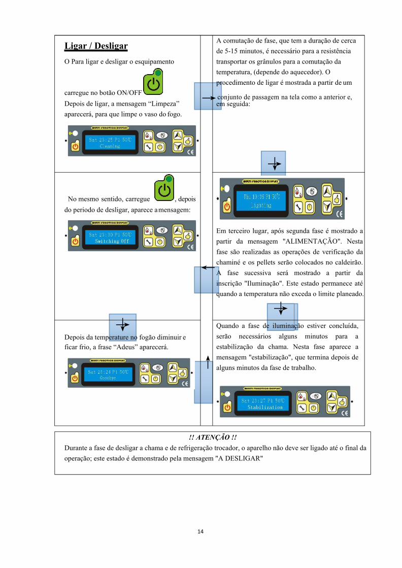
Ligar / DesligarO Para ligar e desligar o esquipamento
carregue no botão ON/OFFDepois de ligar, a mensagem “Limpeza”aparecerá, para que limpe o vaso do fogo.
A comutação de fase, que tem a duração de cercade 5-15 minutos, é necessário para a resistênciatransportar os grânulos para a comutação datemperatura, (depende do aquecedor). Oprocedimento de ligar é mostrada a partir de um
→conjunto de passagem na tela como a anterior e,em seguida:
→↓
No mesmo sentido, carregue , depoisdo periodo de desligar, aparece amensagem:
↓→Depois da temperature no fogão diminuir eficar frio, a frase “Adeus” aparecerá.
Em terceiro lugar, após segunda fase é mostrado apartir da mensagem "ALIMENTAÇÃO". Nestafase são realizadas as operações de verificação dachaminé e os pellets serão colocados no caldeirão.A fase sucessiva será mostrado a partir dainscrição "Iluminação". Este estado permanece atéquando a temperatura não exceda o limite planeado.
→↓Quando a fase de iluminação estiver concluída,serão necessários alguns minutos para aestabilização da chama. Nesta fase aparece amensagem "estabilização", que termina depois dealguns minutos da fase de trabalho.
!! ATENÇÃO !!Durante a fase de desligar a chama e de refrigeração trocador, o aparelho não deve ser ligado até o final daoperação; este estado é demonstrado pela mensagem "A DESLIGAR"
←
↑

15
!! ATENÇÃO !!Se o aquecedor for desligado, a chama vai continuar a estar presente até o esgotamento do combustívelcontido no caldeirão, esta fase irá aparecer de forma automática e terá a duração até 5-8 minutos.
Nota: se a ignição falhar, o controle térmico será desligado o fogão automaticamente. Enquanto isso, E2 (erro dafalha de ignição), será ligado no visor, se quiser reiniciá-lo novamente, por favor verifique o fogão comonormalmente e limpe a panela do fogo. Depois disso, tem de empurrar para limpar a frase E2. Siga o processoacima para inflamar e começar de novo.
NO ENTANTO, é possível desligar o aquecedor em cada fase de funcionamento. Para desligar basta
pressionar o botão ligar/desligar por dois segundos, certifique-se que está a ver o fogão, atéà sua “estabilização”. Depois pressione o botãoe a frase “A ARREFECER”aparecerá.
Depois da temperature do fogão descer, o fogão reiniciará, Limpeza-Alimentação-Ligação-Estabilização.-------------------------------------------------------------------------------------------------------------------
Como fazer o fogão avançar imediatamente o processo de estabilização durante as primeiras fases, quandoachar que a chama está bem e / ou o fogão funciona correctamente?
Carregue durante 3 segundos, e depois irá ligar a estabilização automaticamente.
A fase de desligar é exibida a partir da mensagem "DESLIGAR" apresentada até o final daoperação.Independentemente se aquecedor estiver ligado ou não, o visor irá exibir a hora, o poder, e opainel de temperatura.
Nota: quando utilizado o fogão pela primeira vez, é necessário colocar uma mão de pellets para a
panela do fogo antes da mão.

16
ESTADO ECOSe a temperatura ambiente for superior ao estabelecido, automaticamente o fogão parará para ECO1 ouvolta para o mínimo de energia, a fim de economizar energia Eco2, como se segue:
Após a temperatura ambiente cair, e abaixo do estabelecido (3grau), ele liga automaticamente ou voltaao nível de potência anterior. Mais tarde, será exibido como seleccionar estas duas funções.
Se estiver ligado, o programa seleccionado sera o automático, caso contrário será o manual.estará ligado/desligado., aparecerá o seguinte,Ao pressionar os botões
SELECÇÃO automática e manual
VARIAÇÃO DO PODER DA CHAMADependendo do pretendido, a quantidade de admissão de combustível pode ser ajustada a partir dobotão de admissão de combustível. Por exemplo,
Ao pressionar o botão a quantidade de alimentação pode ser alterada, o visor mostra o poder
selecionado.
POTÊNCIA MINIMA P4 POUCA POTÊNCIA P3
POTÊNCIA MÉDIA P2 POTÊNCIA MÁXIMA P1
17
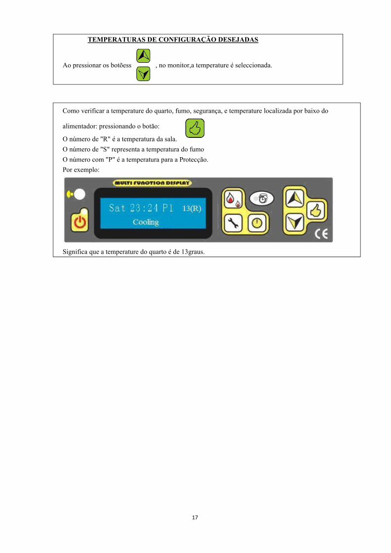
Como verificar a temperature do quarto, fumo, segurança, e temperature localizada por baixo do
alimentador: pressionando o botão:
O número de "R" é a temperatura da sala.O número de "S" representa a temperatura do fumoO número com "P" é a temperatura para a Protecção.Por exemplo:
Significa que a temperature do quarto é de 13graus.
, no monitor,a temperature é seleccionada.Ao pressionar os botõess
TEMPERATURAS DE CONFIGURAÇÃO DESEJADAS

18
3.) Como definer detalhes
Configuração – rápido guia de referência
19
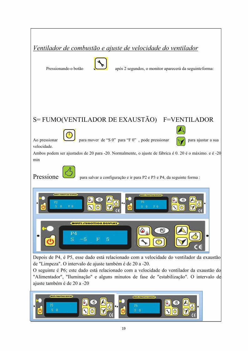
Ventilador de combustão e ajuste de velocidade do ventilador
Pressionando o botão após 2 segundos, o monitor aparecerá da seguinteforma:
S= FUMO(VENTILADOR DE EXAUSTÃO) F=VENTILADOR
Ao pressionar para mover de “S 0” para “F 0” , pode pressionar para ajustar a suavelocidade.Ambos podem ser ajustados de 20 para -20. Normalmente, o ajuste de fábrica é 0. 20 é o máximo. e é -20min
Pressione para salvar a configuração e ir para P2 e P3 e P4, da seguinte forma :
Depois de P4, é P5, esse dado está relacionado com a velocidade do ventilador da exaustãode "Limpeza". O intervalo de ajuste também é de 20 a -20.O seguinte é P6; este dado está relacionado com a velocidade do ventilador da exaustão do"Alimentador", "Iluminação" e alguns minutos de fase de "estabilização". O intervalo deajuste também é de 20 a -20

20
, o tempo pode ser alterado:
Configurações de limpezaPode ajustar o tempo e a limpeza durante a operação “a cada X minutos, dura Y” segundosparalimpar o vaso queimador pelo botão
Por exemplo, a cada 30minutos dura 15 segundos:
e avance para a próxima fase.
pode alterar o dia ou hora, para guarder as alterações pressioneAo utilizar
,Pode seleccionar semana ou tempo pelo botão
Pressione o botão
Configurações de relógio

21
Com esta função, pode selecionar linguagem aopressionar a tecla.
aparecerá o seguinte:Ao manter pressionado o botão
Definições de idioma
Na linha acima são exibidos os dia, que é a programação, a hora com o estado de funcionamento.Na linha abaixo da hora programada são exibidos.Abaixo significa desligado, mais alto significa ligado, também exibido na linha superior.
para decidir a hora, para seleccionar horas, pressioneAo pressionar
Ligada/Desligada..
para escolher os dias da semana,Pode pressionar depois
, irá encontrar as instruções acima indicadas,Ao manter pressionado o botão
Com esta função pode programar o aquecedor para uma programação semanal, associando a ligare desligar nos horários pré fixos. Pode programar diariamente ligar e desligar durante toda asemana.
até à próxima etapa: No visor a seguinte redacção apareceráPressione o botão
Configurações de Tempo

22
changed.
, pode escolher “Sim” ou “Não” – vá para trás nas configurações “Não” – utilize osPelodados que tiver.
aparecerá o seguinte:Ao manter pressionado o botão
Restaurar padrões
para seleccionar o Modo 1 ou Modo 2, o Modo 2 é para virar para opoder, enquanto o modo 1 é para parar o fogão.
Pressione o botãomínimo
aparecerá o seguinte:Ao manter pressionado o botão
Configurações de modo ECO
Ao pressionar o botã o programa irá terminar

23
!! ATENÇÃO!!
*******************************************************
Isto significa que o fogo se vai apagar
automaticamente durante a operação, quando
a temperatura dos gases de escape estiver
abaixo de 40-45 graus.
Tais como: 1. Não existe combustível no
depósito.
2. Broca do motor está partida e pára de
alimentar o combustível.
Isso significa ignição fraca no início.
Tais como: 1. Existência de clinkers em pote de
fogo.
2. O pote de fogo não está colocado
correctamente.
3. A mudança, que está localizado ao lado do
ventilador de combustão para testar o sensor de
temperatura dos gases de escape, está partida.
4. Dispositivo de ignição está partido.
Isso significa que existe um terramotodurante o tempo de operação ou está ainclinar o fogão.
Problema para o sensor de temperatura.Desligado ou partido ou a temperatura da águaestá muito alta (Esta função apenas para a versãode salamdra com água quente).
Isto significa que existem algunsproblemas com o interruptor do vácuo.Tal como porta não foi fechadacorrectamente; A velocidade do ventiladorde combustão não pode acelerar; Há algumvazamento sobre o fogão ou tubo de escapeé bloqueado e assim por diante.
Isto significa que o sensor de temperaturaestá elevado ou localizado abaixo do funil e
tem alguns problemas, tais como: 1.Interruptor partido;
2. Temperatura muito alta e o fogão nãofunciona correctamente
Durante a operação, o fogão é interrompidopor corte de electricidade.
Isso significa que precisa limpar os fogões.

24
Se verificar que está tudo bem, você pode pressionar para apagar o código
de erro.!! ATENÇÃO !!
Se exibir as seguintes mensagens quando iniciar o fogão, tais como:
Isso significa que um sensor de temperatura(sensor de temperatura dos gases de escape)é de curto-circuito.
sso significa que o sensor de temperatura éum circuito aberto.
Isso significa que o sensor de temperatura 2(sensor de temperatura de segurança abaixodo funil) é de curto-circuito.
Isso significa que o sensor de temperatura 2é de circuito aberto.
Isso significa que o sensor de temperatura 3(para o ensaio do sensor de temperaturaambiente, que está localizado na parte detrás) é de curto-circuito.
Isso significa que o sensor de temperatura 3está em circuito aberto.
4. )SegurançaFALTA DE ENERGIAApós a falha de energia, o visor irá mostrar E7. Se falhar a energia curta, pode fazermanualmente voltar para "estabilização" pela Clear o E7 pelo botão "ok", reiniciando o fogãoe, em seguida, mantendo pressionado por 3 segundo o "botão de fogo""Em caso de falha de energia, uma pequena quantidade de fumo pode ser emitida. Isso nãodura mais do que três a cinco minutos e não representa um risco de segurança.
ALIMENTAÇÃO DA TOMADA (contém o fusível principal)ELECTRIC EXCESS-CURRENT SHUT OFF
O dispositivo está protegido contra o excesso de corrente através de um fusível principal (na
parte de trás do dispositivo),
25
A seguir apresenta-se uma lista de componentes principais e as suas funções.
IGNIÇÃO
O fogão vem equipado com um dispositivo de ignição automático para acender o combustível
quando está em modo de alimentação e iluminação.
INTERRUPTOR DE VÁCUO
O fogão tem um vácuostato localizado atrás da porta esquerda, fixado à base. Se existir uma baixa
pressão esta pode criar na fornalha um vazamento, abrindo a porta da frente, uma chaminé
bloqueada ou gaveta para cinzas não lacradas, o vácuostato vai senti-lo e fazer com que o fogão se
desligue, mostrando-E5 .
BROCA E BROCA DO MOTOR
O motor do eixo helicoidal 2 RPM transforma o trado, levantando pellets até o tubo da broca. Os
pellets irão então cair de um tubo e no braseiro. O motor do eixo helicoidal é controlado pela
placa de controlo.
PROTEGER SENSOR DE TEMPERATURA Para evitar o superaquecimentoUm interruptor de temperatura de segurança desliga o fogão e desliga automaticamente emcaso de sobreaquecimento. Depois do fogão arrefecer mostra E6. Se a operação deaquecimento continuar e não depender das brasas remanescentes na panela de fogo. Depoisde remover o código de erro pelo botão "Ok", se re-ignição não ocorrer quando o suprimentode combustível recomeçar, então o programa de funcionamento (limpeza) é realizada. Deacordo com o modo pré-definido o fogão deve ser reiniciado.
FUNÇÃO DO SENSOR DE TEMPERATURA DE EXAUSTÃO TEM POUCA
TEMPERATURA
Se o fogão esfriar abaixo de uma temperatura mínima, o fogão desliga-se. Este interruptor
também pode ocorrer se o pré-aquecimento for muito lento.
ATENÇÃO: Se ocorrer superaquecimento é então necessário manutenção oulimpeza de trabalho.
26
ATENÇÃO: Só funciona no fogão quando o plugue da rede for removido do soquete.
Durante a montagem não deixe cair nenhum item (parafusos), etc para o recipientede combustível - eles podem bloquear a broca transportadora e danificar o fogão.
O fogão deve estar desligado e ter arrefecido antes de trabalho ser realizado.
Não limpar esta unidade fará com que ele queime mal e vai evitar a garantia do seu
fogão.
6. Limpeza e Manutenção
A frequência com que o seu fogão deve ser limpo, bem como os intervalos de manutençãodepende do combustível que utilizar. Alto teor de humidade, cinzas, poeira e chips podemmais do que dobrar os intervalos de manutenção necessários. Salienta-se mais uma vez que sódeve usar pastilhas de madeira testados e recomendados como combustível.Alavanca OperacionalA salamandra vem com uma alça operacional que é usada para abrir ou fechar a grelha.Utilize este identificador de operação para:● Limpeza da panela de fogo; Soltando os pellets no recipiente eles devem ficar para o ladodas paredes;Madeira como fertilizanteResíduo mineral de madeira (aproximadamente 1% a 2%) permanece na câmara decombustão em forma de cinzas. Esta cinza é um produto natural e é um excelente fertilizantepara todas as plantas no jardim. No entanto as cinzas devem ser envelhecidas primeiro e"temperadas" com água.CUIDADO: Brasas podem estar escondidos nas cinzas – apenasestá vazio os recipientes de metal.

27
LIMPEZA DA BANDEJA DE INCÊNDIO
CUIDADO: a panela de fogo deve ser limpa diariamente.Tenha absoluta certeza de que a cinza ou clínquer não bloqueia as aberturas de alimentaçãode ar. A panela de fogo pode ser facilmente limpa no interior do fogão. Depois de retirar otabuleiro da área por baixo pode ser aspirado elimpo.
Cuidado: apenas em estado frio, quando as brasas se apagam! Verifique a panela para oassento correto.Verifique se a bandeja está corretamente assentada.
LIMPEZA DA GRELHA DE VIDROA melhor maneira de limpar o vidro da grelha é utilizando um pano húmido com pequenaquantidade de cinzas da fornalha. Sujeiras mais difíceis podem ser removidas com umaspirador especial que pode ser adquirido com o revendedor do fogão.
LIMPEZA DAS CONDUTAS DE PASSAGEM DO GÁS
A limpeza das passagens de combustão deve ser feita pelo menos uma vez por ano. Queimando
pellets maiores podem exigir que esta limpeza seja feita com mais freqüência. Limpe estas
passagens apenas quando o fogão e cinzas estão frios, pois pode iniciar um incêndio no aspirador
de pó por aspirar cinzas quentes. Em cada lado do forno, existem duas tampas de acesso (ver o
quadro a seguir), que pode ser removido desenroscando os dois 5/32 parafusos de cabeça Allen.
Insira uma escova de limpeza nas aberturas para soltar qualquer acumulação de cinzas e use um
aspirador de pó para remover a cinza solta. Recoloque as tampas quando a limpeza estiver
Se o fogão for aquecido em operação contínua, em seguida, ele deve ser desligadoduas vezes no prazo de 24 horas, a fim de limpar a panela. (perigo de flash back)

28
concluída. Há também mais dois orifícios de acesso localizados atrás da gaveta de cinzas.
Retire a gaveta de cinzas (ver página anterior) e solte os dois 5/32 parafusos allen'' mostrados com
D no desenho abaixo. Gire as coberturas sobre os orifícios de acesso e use um pincel e aspirador
para limpar a cinza. Gire as tampas sobre os buracos e aperte os parafusos. Vista frontal Olhando
para a Gaveta de Cinzas com a gaveta de cinzas Removido.
COMO LIMPAR O FOGÃO
LIMPEZA DO VENTILADOR DE TRANSMISSÃO
29
Para limpar o ventilador, desligue o cabo de alimentação do fogão da tomada eléctrica. Remova
os painéis laterais e traseiro (Para todos os modelos) (e tampa inferior frontal para NB-PI, NB-PS,
NB-P01, NB-PE09). Um vácuo pode ser usado para remover qualquer acumulação de poeira
sobre as pás do ventilador ou no interior da conduta do ventilador. Deve ser tido cuidado adicional
para não danificar as pás do ventilador durante a limpeza.
LIMPEZA DO TUBO DE VENTILAÇÃO
Fuligem e cinzas volantes: Formação e necessidade de remoção
Os produtos de combustão contém pequenas partículas de cinzas volantes que se acumulam no
sistema de evacuação dos fumos e restringem o fluxo dos gases de combustão. A combustão
incompleta, como ocorre durante a inicialização, desligamento ou o aquecimento incorrecto da sala,
vai levar a alguma formação de fuligem que irá acumular-se no sistema de ventilação de escape. O
sistema de ventilação de exaustão deve ser inspeccionado pelo menos uma vez por ano para
determinar se a limpeza é necessária. Varrer o tubo, conforme necessário.
Um T e de limpeza no sistema de ventilação ligado a coleira de combustão do fogão vai facilitar
essa limpeza.
Obrigatório um programar as limpezas após alguns sacos ardidos
Vaso de Queimar=10 bags
Gaveta de cinzas=50 bags
Ventilador de combustão=100 bags
Ventilador=100 bags
NOTA: A limpeza irá variar dependendo da qualidade das pastilhas usadas. Pellets maiores
exigem limpezas mais frequente.

30
7. Resolução de problemasCOMO SUBSTITUIR BARRA DE IGNIÇÃO E A
BROCA
COMO SUBSTITUIR O VENTILADOR DO QUARTO
COMO SUBSTITUIR O VENTILADOR DE COMBUSTÃO

31
Os problemas gerais, as possíveis razões e as soluções são as seguintes, após a resolução de
problemas, inicie o fogão novamente:
Problemas Razões Soluções
1. A luz de início ou o
visor não se acende
quando está ligado
Nenhuma potênciano fogão
ou no painel central
Verifique a potência e os fios.
Fusível partido. Substitua o
fusivel
2. O ventilador não É normal. Por favor aguarde.
funciona depois de Ele vai começar
pressionar a parte inferior automaticamente quando a
para começar. temperatura estiver acima de

32
Se após a estabilização,
ele não trabalhar.
30 graus no tubo de
ventilação.
Nenhuma potência no fogão
ou no painel de controlo.
Ou Unplugged na placa mãe.
O sensor de temperatura
baixa está avariado.
Verifique a potência e os fios.
Ligue-o.
Substitua-o.
3. Sem alimentação após 20 segundos de partida.
Existem três etapas para o processo de alimentação.
Um deles é durante os vários minutos, a alimentação é constante. "Alimentação" aparece no
monitor LCD.
O segundo é depois de alguns minutos, a luz de alimentação está desligada:. "Light",
mostrando no visor
A última etapa é que se alimenta de vários segundos após as fases anteriores.
A. Para a primeira fase
(primeiro durante vários
minutos)
Unidade de alimentação
está bloqueada.
Confira se a verruma está bloqueado
ou não.
Existe um problema sobre
a conexão entre o motor e
o eixo helicoidal
Confira o parafuso e aperte entre a
broca e o motor se está solta ou não.
Ou a broca pode saltar para fora
Sem combustível no
depósito.
Encha o combustível para dentro do
depósito.
B. Para a segunda etapa É normal. Por favor seja paciente.
C. Em relação à última
etapa
Unidade de alimentação
está bloqueada.
Confira se a verruma está bloqueada
ou não.
Existe um problema sobre
a conexão entre o motor e
o eixo helicoidal
Confira o parafuso e aperte entre
broca e motor solta ou não.
Ou a broca pode saltar para fora.
No fuel in the hopper. Fill the fuel into the hopper.
4. Alimentação não
adequada O nível de velocidade de
Ajuste a velocidade do ventilador de
combustão para cima ou a

33
A. Demais aglomerados
de madeira e não pode
queimar no tempo
alimentação é muito alta quantidade
B. O fogo está fora
devido a um pellet de
madeira pequeno que
pode ser queimado
O nível de velocidade de
alimentação é muito
baixa
Ajuste a velocidade do ventilador de
combustão para baixo ou a
quantidade de alimentação
5 Depois da ignição a
energia é desligada 15min
depois.
A unidade de alimentação
do pellet está desligado
ou o pellet é muito
pequeno.
30 ˚ C quebra o
interruptor da
temperatura ou os fios de
ligação do interruptor
estão soltos.
Interruptor de pressão é
partido no fogão
Verifique a unidade de alimentação
do pellet e reinicie.
Verifique os cabos de conexão ou
altere o interruptor de temperatura
de 30 ˚ C.
Substituir ou reparar o aparelho
6 Fogo laranja ou
preguiçoso,
pellet empilhado, o
carbono no
vidro.
Falta de admissão de ar
para a queima.
Limpe o bloco na barra de portão.
Verifique a porta e junta de vidro da
janela selada ou não.
Verifique o tubo de admissão de ar e
se a ventilação está obstruída ou
não, e limpe-o. Mude para os tubos
de grande diâmetro se os
encanamentos são muito longos e
afectam a combustão.
Ajuste a velocidade do ventilador de
combustão.
Ligue para o revendedor para repor
o programa

34
7 O fogo posto para fora
e energia é desligada
automaticamente.
O funil está vazio.
Sem alimentação de
combustível.
A alimentação de
combustível é muito
pouca.
Baixo interruptor de
temperatura
(30 ˚ C).
Definir temperatura
atingida
Coloque combustível no depósito.
referem-se a (2)
Diminua a velocidade do ventilador
de combustão
Arrefeça o fogão pelo menos 1 hora,
em seguida, opere novamente ou
altera o interruptor de baixa
temperatura (30 ˚ C).
"ECO" no seu normal, espere, após a
temperatura estar definida, ele irá
alternar automaticamente
novamente.
8 O ventilador ainda O interruptor de Altere essa opção.
funciona depois do fogão temperatura baixa (30 ˚
estar quente e a C) é quebrado.
alimentação de
combustível pára.
9. Sem vento quente Combustível Use o estandarte de pellets especiais.
suficiente Inqualificável Altere o ventilador (partido) ou a
Velocidade do ventilador placa mãe.
é muito baixa ou não Limpe os tubos de troca de calor ou
funciona. passagem de combustão.
Tubos de troca de calor
ou passagem de
combustão estão sujos.
10. Mostrando "E5" no Tubo de ventilação está Desligue o forno, verifique o tubo de
visor bloqueado. ventilação.
Feche a porta ou altere o selo.
A porta abre-se ou o selo
precisa ser substituído.
Confira e repare-o.
Ajuste o ventilador de combustão e
35
Existem algumas fugas.
sua velocidade para oferecer mais
pressão no fogão
FUNCIONAMENTO ELÉCTRICO DO GERADOR
O fogão pode ser alimentado com um gás conduzido pelo gerador eléctrico.
No entanto, o regulador eléctrico do gerador pode não ser compatível com a electrónica do
fogão. Quanto maior a qualidade do gerador, maior a oportunidade dele ser compatível com
o fogão.
8. GarantiaEstas condições de garantia são aplicáveis à Áustria , Alemanha e Suíça .
Para efeitos de limitação de danos em tempo útil, a reivindicação de garantia por parte do
requerente deve ser executada no negociante por escrito, utilizando a nota fiscal e indicando a
data da compra, nome do modelo, número de série e razão da reclamação.
GARANTIA
A garantia cobre apenas defeitos de materiais e mão de obra, bem como a entrega de peças de
reposição de forma gratuita. Trabalho e tempos de viagem não estão incluídas na garantia do
fabricante.
Use apenas peças de reposição recomendados ou fornecidos pelo fabricante. A perda da
garantia em inobservância!
A pré-condição para a garantia é que o fogão foi instalado e comissionado correctamente de
acordo com as instruções de uso válidas no momento da compra. A conexão deve ser
realizada por um especialista para tais fogões.
Excluem-se desta garantia peças de desgaste, como vidro, revestimento, revestimentos de
superfície (por exemplo, cabos, painéis), focas, através de fogo, cercas, projectos de placas ,

36
chapas deflectoras, forros da câmara de combustão (por exemplo argila de fogo), cerâmica,
pedra natural , elementos de ignição, sensores, sensores de câmara de combustão e
controlador de temperatura .
Também estão excluídos danos decorrentes de inobservância das instruções do fabricante
para o funcionamento da unidade (por exemplo, o super-aquecimento, o uso de combustíveis
não aprovados, a intervenção incorrecta do fogão, o excesso de tensão eléctrica, um projecto
de chaminé configurado incorrectamente para o fogão, a não execução ou manutenção
deficiente e limpeza, operação incorrecta por parte do utilizador ou de terceiros , etc., ou
causado por tal.
Quaisquer custos incorridos pelo fabricante devido a reclamações de garantia injustificadas
devem ser imputados ao requerente.
1.- A instalação e o comissionamento devem ser feitos pelo nosso serviço técnico da
SERVICRUZ, que possui pessoal treinado.
2.-Você deve solicitar a manutenção do nosso serviço técnico autorizado da SERVICRUZ,
pelo menos uma vez por ano.
A GARANTIA NÃO AFEcTA AS DISPOSIÇÕES DE GARANTIA LEGAL.

37
9. Plano Electrónico

1
FREESTANDING PELLET STOVE(PLEASE KEEP THESE INSTRUCTIONS FOR FUTURE REFERENCE)
A LIFETIME OF WARMTH
*Please read this entire manual before installation and use of
this pellet fuel burning room heater. Failure to follow these
instructions could result in property damage, bodily injury.
*Save these instructions!INSTALLER: THIS MANUAL MUST STAY WITH APPLIANCE!

2
Table of Contents1. Fuel Requirement-------------------------------------------------- 3
2. Stove Features------------------------------------------------------ 4
3. Structure instruction----------------------------------------------- 6
4. Pellet Stove Installation------------------------------------------- 8
5. Operation----------------------------------------------------------- 12
6. Cleaning and Maintenance--------------------------------------- 26
7.Troubleshooting---------------------------------------------------- 30
8. Warranty------------------------------------------------------------ 35
9. Electronic Plan----------------------------------------------------- 36

3
Please ask your pellet stove dealer for tested fuel and a list of monitored fuelmanufacturers. Using poor quality or prohibited pellet fuel will have a negativeeffect on the function of your pellet stove and can also lead to the warrantybecomingnull and void, as well as the product liability connected with this. Observe wasteincineration legislation. Burn only pellets that have been tested.
1. Fuel RequirementPellets are made from wooden waste, from sawmills and planning workshops, as well as fromresidue from forestry operations. These “starting products” are crushed, dried, and pressedinto Pellet “Fuel” without any bonding agent.SPECIFICATIONS FOR HIGH QUALITY PELLETSCalorific Value: 5.3 kWh/kgDensity: 700 kg/m3Water Content: Max. 8% of the weightAsh proportion: Max. 1% of the weightDiameter: 5 - 6.5mmLength: Max. 30mmContents: 100% wood untreated and withoutany bonding agents added (barkproportion max. 5%)Packaging: In sacks, made of environmentally neutral or biologically degradable plastic,or from paper (2-3 layers / similar to cement packaging)
PELLET STORAGEIn order to guarantee problem free burning of the wooden pellets, it is necessary to store thefuel as dry as possible and free from impurities.
This appliance is not intended for use by persons (including
children) with reduced physical, sensory or mental
capabilities, or lack of experience and knowledge, unless they
have been given supervision or instruction concerning use of
the appliance by a person responsible for their safety:
Children should be supervised to ensure that they do not play
with the appliance.
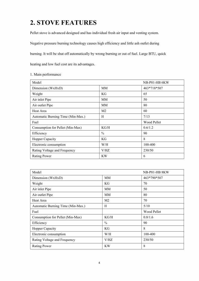
4
2. STOVE FEATURESPellet stove is advanced designed and has individual fresh air input and venting system.
Negative pressure burning technology causes high efficiency and little ash outlet during
burning. It will be shut off automatically by wrong burning or out of fuel. Large BTU, quick
heating and low fuel cost are its advantages.
1. Main performance
Model NB-P01-HB 6KWDimension (WxHxD) MM 463*718*507Weight KG 65Air inlet Pipe MM 50Air outlet Pipe MM 80Heat Area M2 60Automatic Burning Time (Min-Max.) H 7/13Fuel Wood PelletConsumption for Pellet (Min-Max) KG/H 0.6/1.2Efficiency % 90Hopper Capacity KG 8Electronic consumption W/H 100-400Rating Voltage and Frequency V/HZ 230/50Rating Power KW 6
Model NB-P01-HB 8KWDimension (WxHxD) MM 463*790*507Weight KG 70Air inlet Pipe MM 50Air outlet Pipe MM 80Heat Area M2 70Automatic Burning Time (Min-Max.) H 5/10Fuel Wood PelletConsumption for Pellet (Min-Max) KG/H 0.8/1.6Efficiency % 90Hopper Capacity KG 8Electronic consumption W/H 100-400Rating Voltage and Frequency V/HZ 230/50
Rating Power KW 8
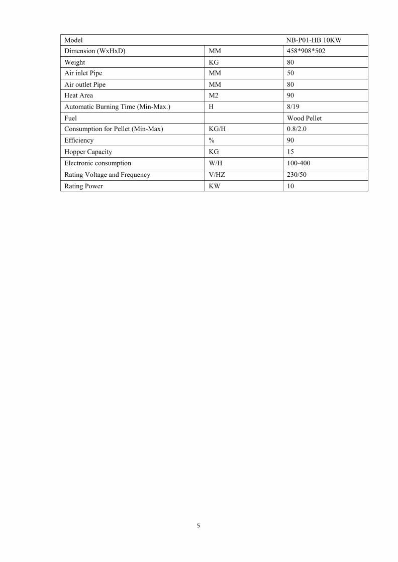
5
Model NB-P01-HB 10KWDimension (WxHxD) MM 458*908*502
Weight KG 80Air inlet Pipe MM 50
Air outlet Pipe MM 80Heat Area M2 90Automatic Burning Time (Min-Max.) H 8/19
Fuel Wood PelletConsumption for Pellet (Min-Max) KG/H 0.8/2.0Efficiency % 90
Hopper Capacity KG 15Electronic consumption W/H 100-400
Rating Voltage and Frequency V/HZ 230/50
Rating Power KW 10

6
3. Structure instructionThe stove is mainly made up of following items:
1. Top covers 2.Door 3.Pellet Hopper 4. Pellet Chamber 5.Ash Drawer 6.Front Top and bottom
Cover 7. Side Panels 8. Chamber Insulation cover 9. Shoulder 10. Hot wind driver
11.Motherboard 12.Fire pot 13. Vacuum Switch. 14. Igniter 15. Combustion fan. 16. Blower 17.
Rear Cover. 18Bottom Clear cover. 19 top clear covers 20. Display. 21. exhaust connection. 22.
Power input socket(contains the main fuse). 23.Room temperature Sensor. 24. Handle. 25 Stove
Feet. 27. Safety temperature Sensor. 28. Exhaust temperature sensor

7
The heater is mainly made up offollowing items - 1. Combustion burnpot 2. Exhaust fan 3. Roomcirculation fan and augermotor.
The following is a list of maincomponents and their functions:
IGNITERThe HEATER comes equipped withan automatic electric igniter forlighting the fuel when the heater is inlighting mode only. The igniterremains energized for the first eightminutes of the lighting sequence.
VACCUM SWITCHThe HEATER has a safety vacuumswitch located behind the left door,fastened to the base. If a low pressureis created in the firebox by a leak,opening the front door, a blocked flue,or unsealed ash drawer, the vacuum
switch will sense it and cause the heater to go into a shutdown mode.
AUGER AND AUGER MOTORThe 2 RPM auger motor turns the auger lifting pellets up the auger tube. The pellets are thendropped down a tube and into the firepot. The auger is controlled by the control board.
OVER TEMPERATURE THERMOSTATThis safety switch is installed on the bottom of hopper and will shut off the heater if it sensesexcessive temperatures (70 degrees).
CONVECTION BLOWER THERMOSTATThis switch is installed on the vent pipe and turns the convection blower on when the heateris above 40 degrees.

8
COMPLETE THE STOVE BEFORE INSTALLATION
Only authorised technical personnel must carry out assembly work.
4. Pellet Stove installationAll NATIONAL AND LOCAL REGULATIONS AND EUROPEAN
STANDARDS SHALL BE COMPLIEDWITHWHEN
INSTALLING THE APPLIANCE
Before install a stove in a room, select the right stove to be able to
heat the room. Please check the STOVES’ Heating area in the
Chapter of STOVE FEATURE.
GENERAL INFORMATIONThe stove must be connected to a chimney that is approved for solid fuels. The chimney musthave a diameter of at least 80 mm.The flue system is based on negative pressure in the combustion chamber and a slightoverpressure on the flue gas outlet. It is therefore important that the flue gas connection isfitted correctly and is airtight.
In addition you must ensure that the flue tube does not project into the free cross section ofthe chimney.
Ensure that outlet routes to the chimney are not too long.Avoid too many changes of direction for the flue gas flow to the chimney. (e.g. too manycorners and bends).Where you cannot connect directly to the chimney, if possible use a connection piece with
NOTE: Please follow the regionally valid building regulations. Contact your masterchimney sweep for information on this.
Only use heat resistant sealing materials, as well as the relevant sealing bands,heat resistant silicon and mineral wool.

9
cleaning opening.For optimum efficiency please use the type of connector we recommend.
MAKING THE CHIMNEY CONNECTION
Horizontal(But it is not recommended, when the electronic
power is off, the smoke might come out if the stove is on)
Horizontal and Up through the eave
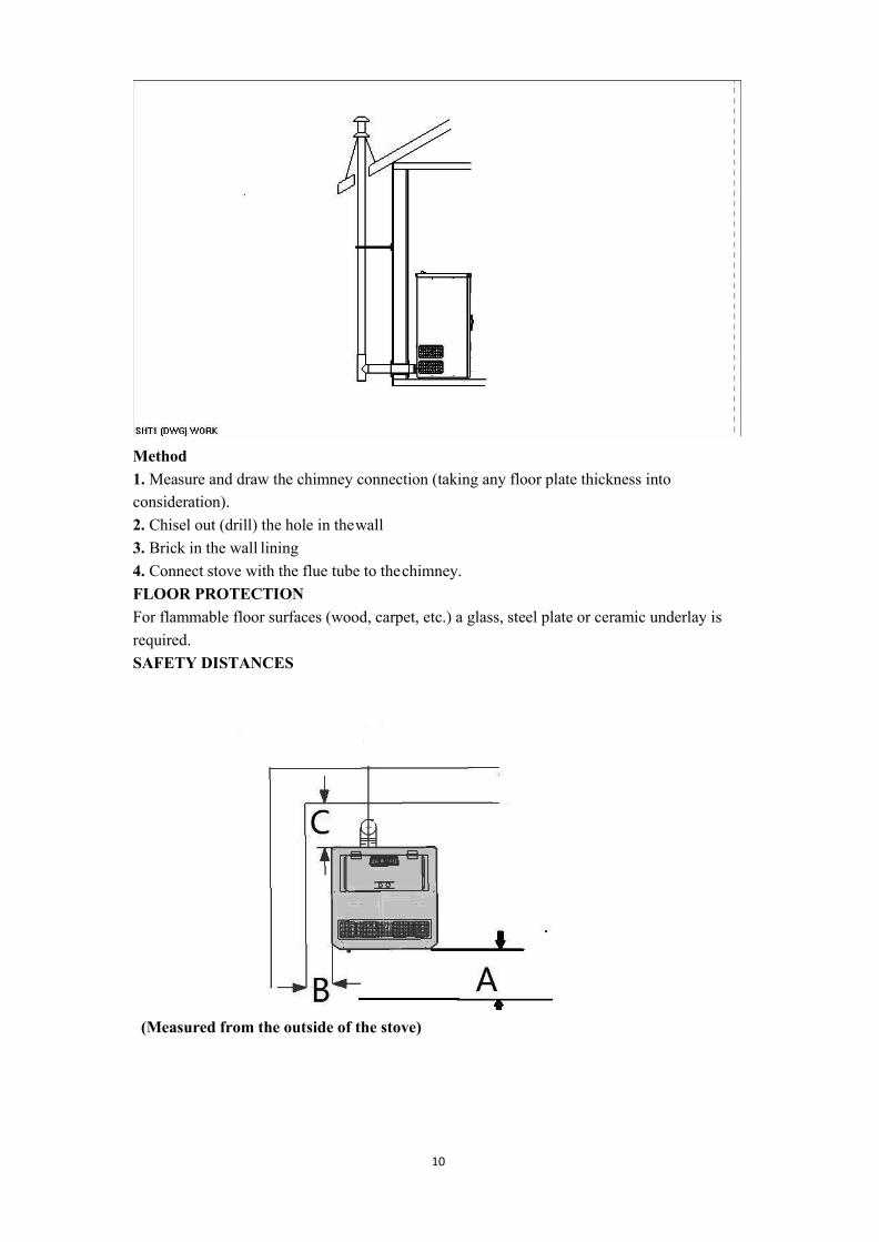
10
Method1.Measure and draw the chimney connection (taking any floor plate thickness intoconsideration).2. Chisel out (drill) the hole in thewall3. Brick in the wall lining4. Connect stove with the flue tube to thechimney.FLOOR PROTECTIONFor flammable floor surfaces (wood, carpet, etc.) a glass, steel plate or ceramic underlay isrequired.SAFETY DISTANCES
(Measured from the outside of the stove)

11
From non-combustible objectsA > 400 mm B > 100 mm C > 100mmFrom combustible objects and to load-bearing walls in reinforced concreteA > 800 mm B > 200 mm C > 200mm
E N G L I S HELECTRICAL CONNECTIONThe stove is supplied with an approx. 2 m long connecting cable with a plug. The cablemust be connected to a 230 V, 50 Hz electrical supply. The average electric powerconsumption is approx 100 watts during heating. During the automatic ignition process(duration 10 minutes) approx. 350 watts. The connection cable must be laid so that anycontact with hot or sharpedged external surfaces on the stove isavoided.COMBUSTIONAIREach combustion procedure requires oxygen or air. As a rule this combustion air is removedfrom the living area for individual stoves The air taken from the living area must bereintroduced. In modern houses, very tight fitting windows and doors mean that too little airflows back. This situation becomes problematic due to additional ventilation in the house (e.g.in the kitchen orWC).The suctioning in of combustion air is performed via the flue gas blower. The resultingcombustion air and suctioning noises are normal operational noisesthat may occur at varying volumes depending on the chimney draught, output level or a dirtycombustion trough – NOT A CAUSE FOR COMPLAINT!Feed of external combustion air● Steel, HT or flexible aluminium pipes must be used.● Minimum diameter 5 cm/2 inches.● For longer connection runs the diameter must be increased to approx. 10 cm after approx. 1m.● The pipe should not be longer than approx. 4m in total to guarantee adequate air feed andnot have too many bends.● Should the line lead into the open air, it must end with a vertical 90° downward elbow orwith a wind guard.Should one or more of these conditions NOT be applicable then usually poor combustion willoccur in the stove, as well as air under pressure in the apartment.
We recommend that a ventilating grille be fitted in a window near the stove for permanentventilation. Further it is possible to extract the combustion air directly from outside or fromanother room that is well ventilated (e.g. the cellar).Please observe:Your pellet stove works independent of the room air. Negative pressures in the set-up roomare not permissible. Therefore the use of a safety device (e.g. differential pressure controller)in combination with room air facilities (e.g. ventilation system, exhaust extraction etc.) isstipulated.

12
Note: When first time’s running, the paint can be get rid of by burning. So some
unpleasant Smell might come out. Please open the window and door to vent the smell.
Note: If the new stove, when its first time using, it is necessary to put a handful of
wood pellet to the fire pot before hand.
Note: Keep the fire pot and its underneath clean when every time you start the stove!
5. OperationALL NATIONAL AND LOCAL REGULATIONS AND
EUROPEAN STANDARDS SHALL BE COMPLIEDWITHWHEN
OPERATING THE APPLIANCE
Attention: When the stove in operation ,please don't touch the front
of it. Its extremely hot!
Put wood pellet fuel into the hopper, connect the power. Then On/Off Light is Lighting (It means
that power is on). Operate as the instruction on section “start and operation”
Start and operation USERS GUIDE
Please operate the stove as following (refer to stove structure figure and electrical control figure):
Check the box, pellet grate bar,ash pan then adjust to proper position.
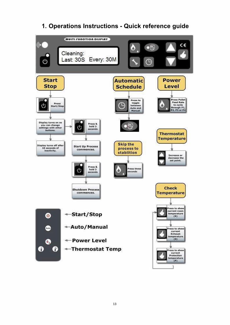
13
1. Operations Instructions - Quick reference guide
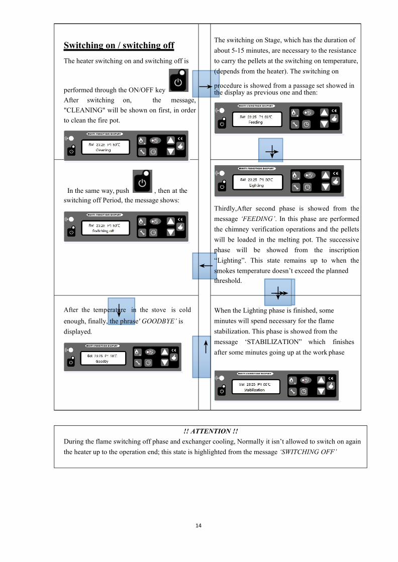
14
→
Switching on / switching offThe heater switching on and switching off is
performed through the ON/OFF keyAfter switching on, the message,"CLEANING" will be shown on first, in orderto clean the fire pot.
In the same way, push , then at theswitching off Period, the message shows:
The switching on Stage, which has the duration ofabout 5-15 minutes, are necessary to the resistanceto carry the pellets at the switching on temperature,(depends from the heater). The switching on
→procedure is showed from a passage set showed inthe display as previous one and then:
↓→
Thirdly,After second phase is showed from themessage ‘FEEDING’. In this phase are performedthe chimney verification operations and the pelletswill be loaded in the melting pot. The successivephase will be showed from the inscription“Lighting”. This state remains up to when thesmokes temperature doesn’t exceed the plannedthreshold.
After the temper↓ature in the stove is coldenough, finally, the phrase' GOODBYE’ isdisplayed.
→↓→When the Lighting phase is finished, someminutes will spend necessary for the flamestabilization. This phase is showed from themessage ‘STABILIZATION” which finishesafter some minutes going up at the work phase
!! ATTENTION !!During the flame switching off phase and exchanger cooling, Normally it isn’t allowed to switch on againthe heater up to the operation end; this state is highlighted from the message ‘SWITCHING OFF’
←
↑

15
!! ATTENTION !!If the heater is switched off, the flame will continue to be present up to the fuel exhaustion contained in themelting pot, this phase will manage in automatic way both fans and it will have the duration up to 5-8minutes.
Note: if the ignition is failure, the thermal control will shut off the stove automatically. Meanwhile, E2 (Error forthe ignition failure), will be turned on the display, If want to restart it again, Please Check the stove as usuallyand cleaning the fire pot. After that, you have to push to clean the Phrase E2. Follow the above processto ignite and start again.
HOWEVER, It is possible to switch off the heater in every functioning phase. The switching off performs
pressing the key ON/OFF for two seconds, make sure the stove is under your eyes, until its“Stabilisation”, After push the button, then the phrase "Cooling" comes
After the stove’s temperature falling down, the stove starts again, Cleaning-feeding-lighting-stabilization.-------------------------------------------------------------------------------------------------------------------
How to make the stove immediately skip the process to Stabilization During the first several stages when youthink the flame is ok and/or the stove can work properly?
Push for 3 seconds, and then it will turn on Stabilizationdirectly.
The switching off phase is displayed from the message ‘SWITCHING OFF” present up to theend of the operation.Whether the heater is switched or not, on the display will display the hour, the power, and theplanned set temperature.
Note: If the new stove, when its first time using, it is necessary to put a hand of pellet to the fire pot
before hand.

16
ECO STAGEIf the room temperature exceeds the set out temperature, automatically the stove is stopped Eco1 orturns to minimum power in order to save energy Eco2, It shows like following:
After the room temperature drops down, and below the set out temperature (3degrees), it automatically,switching on again or come back to the previous Power level. Later how to select these two functionswill be shown.
If the light is on, it shows that automatic program is selected. Otherwise it is manual.will be on/off., The light shown on the following,Pressing the keys
Automatic and manual SELECTING
, on the display The temperature is selecting.Pressing the keys
DESIRED TEMPERATURESSETTING
FLAME POWER VARIATIONDepending on the heating desire, fuel intake quantity can be adjusted from few to large by the fuelintake Button. For example,
Pressing the key the feed quantity can be changed, the display shows the selectedpower.
MINIMUM POWER P4 LOW POWER P3
MEDIUM POWER P2 MAXIMUM POWER P1

17
How to Check the Room temperature, Exhaust (Smoke) Temperature, Safety (Protection) Temperature
which is located under the hopper-------------------By Push button
The number with “R” is the temperature for room.The number with “S” is the temperature for theSmokeThe number with “P” is the temperature for the Protection.For example:
It means that the room temperature is 13 degree.

18
3.) How to set details
Setup - Quick reference guide
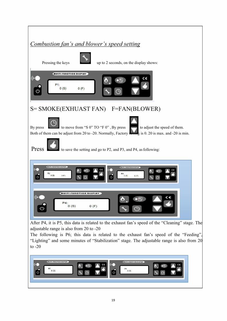
19
Combustion fan’s and blower’s speed setting
Pressing the keys up to 2 seconds, on the display shows:
S= SMOKE(EXHUAST FAN) F=FAN(BLOWER)
By press to move from “S 0” TO “F 0” , By press to adjust the speed of them.Both of them can be adjust from 20 to -20. Normally, Factory setting is 0. 20 is max. and -20 is min.
Press to save the setting and go to P2, and P3, and P4, as following:
After P4, it is P5, this data is related to the exhaust fan’s speed of the “Cleaning” stage. Theadjustable range is also from 20 to -20The following is P6; this data is related to the exhaust fan’s speed of the “Feeding”,“Lighting” and some minutes of “Stabilization” stage. The adjustable range is also from 20to -20

Power, while mode 1 is for stopping the stove.
, to select the Mode 1 or Mode 2, Mode 2 is for turning to minimumPressing the key
it will appear the following words:By keeping pressing the key
ECO mode SETTING
20
.With this function you can select language.By pressing the key
it will appear the following words:By keeping pressing the key
LANGUAGE SETTING
CLEANING SETTING
you can adjust the time of cleaning duringthe operation------------“every X mins, last Y”Secondsto cleaning the burning pot by the key
For example every 30mins Last 15 seconds:

21
, the time can be amended:
and move to next stage.
to change the day or time , to save the correct data by pressalso using
,You can select week or time by keys
Press the key
CLOCK SETTING

22
TIMER SETTING
Press the key into next stage: On the display the following wording will appear
With this function you program the heater for a weekly programming, associating the switchingon and the switching off at the pre fixed timetables. You can program daily switching on andswitching off for the whole week.
By keeping pressing the key , you will found the attached instructionabove,
Then you can press to choose week days
By pressing , to select hours, then press to decide the hour on or Off.
On the above line it is showed the day which is programming, the hour with the functioningstate.On the below line the programmed hour are displayed. Lower one means off, taller on means on, which also shows on superior line
Restore Defaults select
Keeping pressing the key it will appear the following words
By , you can choose Yes, Or No. “Yes”- go back factory setting “NO” - use the data you havechanged.
Pressing the ke the programming will finish.!! ATTENTION !!
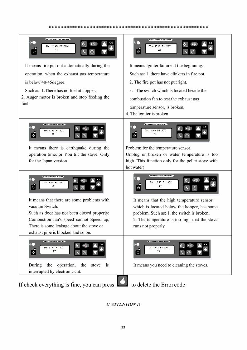
23
*******************************************************
It means fire put out automatically during the
operation, when the exhaust gas temperature
is below 40-45degree.
Such as: 1.There has no fuel at hopper.2. Auger motor is broken and stop feeding thefuel.
It means Igniter failure at the beginning.
Such as: 1. there have clinkers in fire pot.
2. The fire pot has not put right.
3. The switch which is located beside the
combustion fan to test the exhaust gas
temperature sensor, is broken,4. The igniter is broken
It means there is earthquake during theoperation time. or You tilt the stove. Onlyfor the Japan version
Problem for the temperature sensor.Unplug or broken or water temperature is toohigh (This function only for the pellet stove withhot water)
It means that there are some problems withvacuum Switch.Such as door has not been closed properly;Combustion fan's speed cannot Speed up;There is some leakage about the stove orexhaust pipe is blocked and so on.
It means that the high temperature sensor,which is located below the hopper, has someproblem, Such as: 1. the switch is broken,2. The temperature is too high that the stoveruns not properly
During the operation, the stove isinterrupted by electronic cut.
It means you need to cleaning the stoves.
If check everything is fine, you can press to delete the Errorcode
!! ATTENTION !!

24
If showing following words when you start the stove, such as:
It means temperature sensor 1(exhaust gastemperature sensor) is short-circuit.
It meansopen-circuit.
temperature sensor 1 is
It meanstemperatureshort-circuit.
temperature sensorsensor below the
2 (safetyhopper)is
It meansopen-circuit.
temperature sensor 2 is
It means temperature sensor 3(sensor fortesting the room temperature, which islocated on the rear panel) is short-circuit.
It meansopen-circuit.
temperature sensor 3 is
4. )SafetyPOWER FAILUREAfter the power failure, the display will be show E7. If short power failure, you can domanually goes back to "Stabilization" by Clear the E7 by "okay button", restarting thestove and then keeping pressing 3 second of "fire button"On power failure a small amount of smoke may be emitted. This does not last for morethan three to five minutes and does not represent a safety risks.
POWER INPUT SOCKET (contains the main fuse)ELECTRIC EXCESS-CURRENT SHUT OFFThe device is protected against excess current by a main fuse (on the rear of the device),
The following is a list of main components and their functions
IGNITER
The STOVE comes equipped with an automatic igniter for lighting the fuel when the stove is in
feeding and lighting mode.
25
VACCUMSWITCH
The STOVE has s vacuum switch located behind the left door, fastened to the base. If a low
pressure is created in the firebox by a leak, opening the front door, a blocked flue, or unsealed ash
drawer(some model), the vacuum switch will sense it and cause the stove to go into a shutdown
mode by showing E5.
AUGER AND AUGER MOTOR
The 2 RPM auger motor turns the auger, lifting pellets up the auger tube. The pellets are then
dropped down a tube and into the firepot. The auger motor is controlled by the control board.
PROTECT TEMPERATURE SENSOR TO AVOIDOVERHEATING
A safety temperature switch switches the stove off automatically if it overheats,. After thestove has cooled down meanwhile it shows E6. Whether the heating operation is continued ornot depends on the remaining embers in the fire pan. After you remove the Error Code by"Okay button" , If re-ignition does not occur when the fuel supply recommences, then the outof operation program (cleaning , lag phase) is carried out. According to the pre-set mode thestove must be re-started.
EXHUASTED TEMPERATURE SENSOR FUNCTION AS LOW TEMPERATURE
SWITCH OFF
If the stove cools down below a minimum temperature, then the stove will switch off. Thisswitch off can also occur if pre-heating is too slow.
CAUTION: If overheating has occurred then maintenance or cleaning work mustbe carried out.

26
CAUTION: Only work on the stove when the mains plug has been removed from thesocket.
During assembly do not drop any items (screws) etc. into the fuel container - theycan block the conveyor auger and damage the stove.
Your stove must be switched off and have cooled down before work is carried out.
Not cleaning this unit will cause it to burn poorly and will avoid your stove’s
warranty.
6. Cleaning andMaintenance
The frequency with which your stove must be cleaned as well as the maintenance intervalsdepends on the fuel you use. High moisture contents, ash, dust and chips can more thandouble the necessary maintenance intervals. We would like to point out once again that youshould only use tested and recommended wooden pellets as a fuel.Operating handleYour new pellet stove comes with an operating handle that is used for opening or closing thegratedoor. Please use this operating handle for:● Cleaning the fire pan; Loosening the pellets in the pellet container should they stick to thesidewalls;Wood as a fertiliserWood mineral residue (approx. 1 -2%) remains in the combustion chamber as ash. This ash isnatural product and is an excellent fertiliser for all plants in the garden. However the ashshould be aged first and “quenched” with waterCAUTION: Embers may be hidden in the ash – empty only intometal containers.

27
CLEANING THE FIRE PAN
CAUTION: Clean fire pan daily.Make absolutely certain that ash or clinker does not block the air feed openings. The fire pancan easily be cleaned inside the stove. After removing the pan the area underneath can bevacuumed clean.
Caution: only in a cold state, when the embers are extinguished! Check the pan for correctseating.Check that the pan is correctly seated.
CLEANING THE GRATE DOOR GLASSThe best way to clean the grate door glass is using A damp cloth with small amount of ashfrom the firebox. Stubborn dirt can be removed using a special cleaner that can be purchasedfrom your specialist stove dealer.
CLEANING THE FLUE GAS PASSAGEWAYS
Cleaning the flue passageways should be done at least once a year. Burning high ash pellets may
require this cleaning to be done more often. Clean these passageways only when the stove and ash
are cold do not start a fire in the vacuum cleaner by vacuuming up hot ash. On each side of the
stove there are two access covers (see the picture as follows) that can be removed by unscrewing
the two 5/32’’ allen head screws. Insert a cleaning brush in the openings to loosen any ash buildup
and use a vacuum cleaner to remove the loosed ash. Reinstall the covers when cleaning is
complete. There are also two more access holes located behind the ash drawer.
If the stove is heated in continuous operation, then it must be switched off twicewithin 24 hours in order toclean the pan. (danger of flash back)

28
Remove the ash drawer (see the previous page) and loosen the two 5/32’’ allen head screws
shown as D in the drawing below. Rotate the covers over the access holes and use a brush and
vacuum to clean the ash. Rotate the covers back over the holes and tighten the screws. Front View
Looking into the Ash Drawer Cavity with the Ash Drawer Removed.
HOW TO CLEAN THE STOVE
Some stoves with pipe cleaners that serve to scrape and clean the pipes through which the smoke
passes.Perform this operation daily before turning the power on..

29
CLEANING THE CONVECTION BLOWER
To clean the convention blower, Disconnect the stove power cord from the electrical outlet.
Remove the side panels and rear panel (For all models) . A vacuum can be used to remove any
dust accumulation on the blower’s blades or inside the blower duct. Caution should be used not to
damage the blower’s blades during cleaning.
CLEANING THE VENT PIPE
Soot and Fly ash: Formation and Need for Removal
The products of combustion will contain small particles of fly ash will collect in the exhaust
venting system and restrict the flow of the flue gases. Incomplete combustion, such as occurs
during start up, shutdown, or incorrect operation of the room heater will lead to some soot
formation which will collect in the exhaust venting system. The exhaust venting system should be
inspected at least once every year to determine if cleaning is necessary. Sweep the pipe as needed.
A tee and the cleanout in the vent system attached to the stove’s flue collar will facilitate this
cleaning.
Required Cleaning Schedule after Number of Bags Burned
Burn Pot=10 bags
Ash Drawer=50 bags

30
Flue Fan=100 bags
Blower=100 bags
NOTE: Cleaning schedule will vary depending on quality of pellets used. Burned high ash
pellets used. Burned high ash pellets will require more frequent cleaning
7. TroubleshootingHOW TO REPLACE INGITION BAR AND AUGER
SYSTEM
HOW TO REPLACE THE ROOM FAN(BLOWER)

31
HOW TO REPLACE THE COMBUSTION FAN
The general troubles, the possible reasons and the solutions are as following, after solving
problems, start the stove again:
problems reason solution
1. The start light or
display does not light
No power in stove or in the
control panel.
Check the power and wires.

32
when power is on
Fuse is broken Replace the
fuse
2. The blower doesn’t
work after pressing the
start bottom.
If after stabilization, it
doest work, there must be
wrong
It is normal.
It will start automatically
when the temperature is
above 30 degrees on the
venting pipe.
Please wait
No power in stove or in the
control panel.
Or Unplugged on the mother
board
The low temperature sensor is
broken
Check the power and wires.
Plug it
Replace it
3. No feeding after 20 seconds of starting.
There are three stages for the feeding process.
One is during the several minutes, feeding is constantly. "Feeding" is showing on the LCD
display
Two is the following couple minutes, the feeding light is off.:"Light" showing on the Display
The last stage is that feeding Every several seconds all the time after previous stages.
A. For the first stage
(during first several
Feed unit is blocked. Check the auger is blocked or not.
There is the problem Check the fasten screw between

33
minutes) about the connection
between motor and auger
auger and motor loose or not.
Or the auger might jump out
No fuel in the hopper. Fill the fuel into the hopper.
B. For the second stage It is normal Please be patient
C. Regarding to the last
stage
Feed unit is blocked. Check the auger is blocked or not.
There is the problem
about the connection
between motor and auger
Check the fasten screw between
auger and motor loose or not.
Or the auger might jump out
No fuel in the hopper. Fill the fuel into the hopper.
4. Feeding not properly
A. too much wood pellet
and cannot burned in time
The level of feeding
speed is too high
Adjust the combustion fan's speed
up or Feeding quantity
B. The fire is off due to
little wood pellet can be
burned
The level of feeding
speed is too low
Adjust the combustion fan's speed
Down or feeding quantity
5 After ignition the power
is off 15min later.
Pellet feeder unit is off or
pellet is too little.
30˚C temperature switch
breaks or the connection
wires of switch loose.
Pressure Switch is broken
in the stove
Check the pellet feeder unit and
restart.
Check the connection wires or
change the 30˚C temperature switch.
Replace or repair the device
6 orange and lazy fire,
piled pellet, carbon on the
glass
Lack of air intake for
burning.
Clean the block in gate bar.
Check the door and window glass
gasket sealed or not.
Check the air intake pipe and
venting pipe blocked or not, and
clean it. Change to the big diameter
pipes if pipes are too long to affect
combustion.

34
Adjust the combustion fan's speed
up
Call the dealer to reset the program
7 The fire put out and
power is off
automatically.
The hopper is empty.
No fuel feed.
The fuel feed is too little.
low temperature switch
(30˚C) is wrong.
Set temperature is
reached
Put fuel into the hopper. refer to (2)
Lower the speed of combustion fan
Cool the stove at least 1 hour then
operate again or change the low
temperature switch (30˚C).
"ECO" its normal, waiting, after the
temperature is blow set on, it will
automatically switch on again
8 The blower still works
after the stove is cool and
fuel feed stops.
The low temperature
switch (30˚C) is broken.
Change this switch.
9 no enough heat wind Unqualified fuel
Blower speed is too low
or not running.
Heat exchange tubes or
flue pass are dirty.
Use the standard specially pellet.
Change the blower(Broken) or the
mother board is broken
Clean the heat exchange tubes or
flue pass.
10. Showing "E5" on the
display
Vent pipe is blocked
The door is opening or
seal needs to be replaced
The are some leakages
Shut down the stove, check the
venting pipe
Close the door or change the seal
Check it and repair it.
Adjust the combustion fan's speed
up to offer more pressure in the
stove
ELECTRICAL GENERATOR OPERATION
Your stove can be powered with a gas driven electrical generator.
However, the generator’s electrical regulator may not be compatible with the stove’s
35
electronics. The higher the quality of the generator, the greater the chance that it is
compatible with the stove.
8. WarrantyThese warranty conditions apply to Austria, Germany and Switzerland.
For the purpose of timely damage limitation, the warranty claim on the part of the claimant is
to be enforced at the GRACE dealer in writing using the invoice and stating the purchase date,
model name, serial number and reason for complaint.
WARRANTY
The warranty only covers defects in materials and workmanship as well as delivery of spare
parts free of charge. Labor and travel times are not included in the manufacturer’s warranty.
Only use spare parts recommended or supplied by the manufacturer. Loss of warranty on
nonobservance!
1.- The installation and commissioning must be carried out by our SERVICRUZ technical
service, which has trained personnel.
2.-You must request maintenance from our SERVICRUZ authorized technical service, at
least once a year..
The warranty excludes WEARING PARTS such as glass, coating, surface coatings (e.g.
handles, panels), seals, fire trough, grates, draught plates, deflector plates, combustion
chamber liners (e.g. fireclay), ceramics, natural stone, ignition elements, sensors, combustion
chamber sensors and temperature controller.
Damage arising from non-observance of the manufacturer’s instructions for operation of the
unit is also excluded (e.g. overheating, use of nonapproved fuels, incorrect intervention in the
stove, electrical excess voltage, a chimney draught set incorrectly for the stove,
non-performance or deficient maintenance and cleaning, incorrect operation by the user or
third parties, etc.) or caused by such.
Any costs incurred by the manufacturer due to unjustified warranty claims are to be charged
to the claimant.
THE WARRANTY DOES NOT AFFECT THE STATUTORYWARRANTY
PROVISIONS.

36
9.Electronic

1
Benutzerhandbuch Pelletofen
Bitte lesen Sie das gesamte Handbuch vor der Installation und Nutzungdieses Pelletofens.
Bewahren Sie dieses Handbuch immer beim Gerät auf!

2
Inhalt:
1 – Bestimmungsgemäßer Gebrauch 32 – Sicherheitshinweise 33 -Anforderungen anden Brennstoff 44 – Eigenschaftendes Ofens 55 - Aufbauanleitung 56 – Bedienungsanleitung 167 -Sicherheit 298 -Wartung und Pflege 309 –Fehlerbehebung 3410 -Gewährleistung 3811 -Schaltplan 39

3
1 - Bestimmungsgemäßer GebrauchDieser Ofen ist nur für das Heizen mit Holzpellets in geschlossenen Räumen bestimmt. DieVerwendung für andere Zwecke, wie zum Beispiel das Heizen mit Klafterholz oder anderenBrennstoffen, ist ausdrücklich verboten! Für andere Verwendungen der Maschine, als denbestimmungsgemäßen Gebrauch erlischt jeglicher Gewährleistungsanspruch.Hinweis: Achten Sie darauf, das Gerät regelmäßig zu reinigen. Verunreinigungen vermindern dasHeizergebnis. Bei Nicht Beachtung erlischt der Gewährleistungsanspruch.
2 – Sicherheitshinweise· Beachten Sie, dass alle nationalen und europäischen Normen, örtliche und baurechtlicheVorschriften sowie Bestimmungen zur Brandsicherheit erfüllt werdenmüssen.
· Vor dem Aufstellen des Ofens sind die Brandschutzvorschriften, bzw. die am Aufstellungsortverbindliche Landesbauverordnung zu beachten. Vor Installation ist mit dem zuständigenörtlichen Bezirksschornsteinfeger Rücksprache zu halten. Dieser prüft auch den Anschluss desKamins.
· Prüfen Sie, ob der Boden am Aufstellort der geforderten Belastung (Tragfähigkeit undBrandsicherheit) genügt.
· Unterschreiten Sie niemals die geforderten Brandsicherheitsabstände zu brennbarenMaterialien.· Kontrollieren Sie das Gerät vor Inbetriebnahme immer auf Vollständigkeit, Funktion undübermäßige Brennstoffrückstände (Aschereste)
· Nehmen Sie niemals ein defektes oder funktionsunfähiges Gerät in Betrieb! Kontaktieren Sie denHersteller oder lassen Sie das Gerät von einem qualifizierten Heizungsbauerkontrollieren.
· Entlüftungseinrichtungen wie z.B. Dunstabzugshauben, die zusammen mit Feuerstätten imgleichen Raum oder Raumluftverbund betrieben werden, können Problemeverursachen.
· Betreiben Sie den Ofen niemals bei geöffneterTüre.· Arbeiten Sie immer mit Bedacht und der nötigenVorsicht!· Bauliche Änderungen an der Feuerstelle sind strengstensuntersagt!· Reinigen Sie regelmäßig den Ofen. Verwenden Sie dabei niemals spitze oder scharfkantigeGegenstände oderWerkzeuge.
· Lagern Sie niemals leicht brennbare oder entzündliche Gegenstände oder Materialien in derNähe des Ofens.
· Sorgen Sie, im Falle von Rauchentwicklung, sofort für ausreichendeBelüftung.· Fassen Sie niemals die heißen Oberflächen des Ofens während des Betriebes ohneSchutzausrüstung (Hitzeschutzhandschuhe) an. Der Ofen wird mit einem Extra Griff für dasÖffnen und Schließen der Türe geliefert. Benützen Sie diesen zum Öffnen der Türe! Siehe Punkt8Wartung und Pflege
· Rufen Sie bei Schornsteinbrand sofort dieFeuerwehr.· Verwahren Sie Verpackungsteile (Folien, Plastikbeutel, Styropor, etc.) nur an Orten auf,dieKindern insbesondere Kleinkindern nicht zugänglich sind, da Verpackungsteile oft nichterkennbare Gefahren bergen (z.B. Erstickungsgefahr)
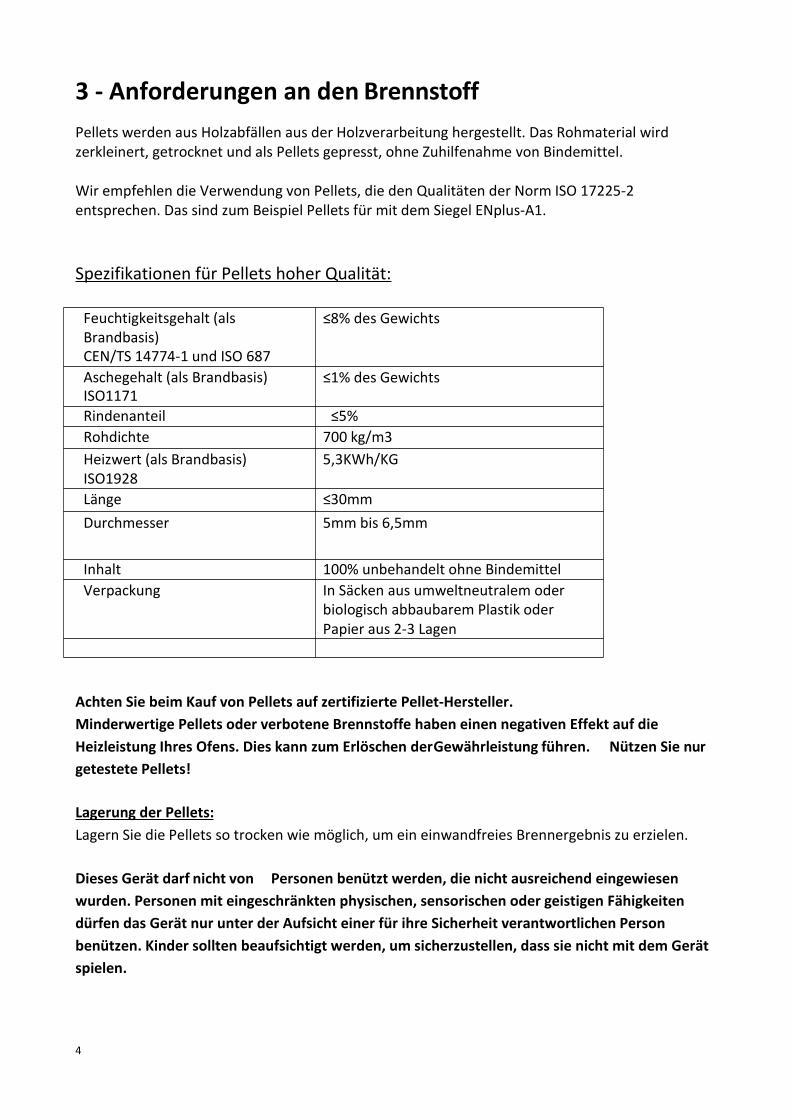
4
3 - Anforderungen an den BrennstoffPellets werden aus Holzabfällen aus der Holzverarbeitung hergestellt. Das Rohmaterial wirdzerkleinert, getrocknet und als Pellets gepresst, ohne Zuhilfenahme von Bindemittel.
Wir empfehlen die Verwendung von Pellets, die den Qualitäten der Norm ISO 17225-2entsprechen. Das sind zum Beispiel Pellets für mit dem Siegel ENplus-A1.
Spezifikationen für Pellets hoher Qualität:
Feuchtigkeitsgehalt (alsBrandbasis)CEN/TS 14774-1 und ISO 687
≤8% des Gewichts
Aschegehalt (als Brandbasis)ISO1171
≤1% des Gewichts
Rindenanteil ≤5%Rohdichte 700 kg/m3Heizwert (als Brandbasis)ISO1928
5,3KWh/KG
Länge ≤30mmDurchmesser 5mm bis 6,5mm
Inhalt 100% unbehandelt ohne BindemittelVerpackung In Säcken aus umweltneutralem oder
biologisch abbaubarem Plastik oderPapier aus 2-3 Lagen
Achten Sie beim Kauf von Pellets auf zertifizierte Pellet-Hersteller.Minderwertige Pellets oder verbotene Brennstoffe haben einen negativen Effekt auf dieHeizleistung Ihres Ofens. Dies kann zum Erlöschen derGewährleistung führen. Nützen Sie nurgetestete Pellets!
Lagerung der Pellets:Lagern Sie die Pellets so trocken wie möglich, um ein einwandfreies Brennergebnis zu erzielen.
Dieses Gerät darf nicht von Personen benützt werden, die nicht ausreichend eingewiesenwurden. Personen mit eingeschränkten physischen, sensorischen oder geistigen Fähigkeitendürfen das Gerät nur unter der Aufsicht einer für ihre Sicherheit verantwortlichen Personbenützen. Kinder sollten beaufsichtigt werden, um sicherzustellen, dass sie nicht mit dem Gerätspielen.
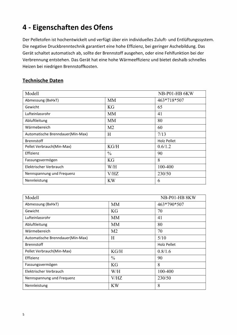
5
4 - Eigenschaften des OfensDer Pelletofen ist hochentwickelt und verfügt über ein individuelles Zuluft- und Entlüftungssystem.Die negative Druckbrenntechnik garantiert eine hohe Effizienz, bei geringer Aschebildung. DasGerät schaltet automatisch ab, sollte der Brennstoff ausgehen, oder eine Fehlfunktion bei derVerbrennung entstehen. Das Gerät hat eine hohe Wärmeeffizienz und bietet deshalb schnellesHeizen bei niedrigen Brennstoffkosten.
Technische Daten
Modell NB-P01-HB 6KWAbmessung (BxHxT) MM 463*718*507Gewicht KG 65Lufteinlassrohr MM 41Abluftleitung MM 80Wärmebereich M2 60Automatische Brenndauer(Min-Max) H 7/13Brennstoff Holz PelletPellet Verbrauch(Min-Max) KG/H 0.6/1.2Effizienz % 90Fassungsvermögen KG 8Elektrischer Verbrauch W/H 100-400Nennspannung und Frequenz V/HZ 230/50Nennleistung KW 6
Modell NB-P01-HB 8KWAbmessung (BxHxT) MM 463*790*507Gewicht KG 70Lufteinlassrohr MM 41Abluftleitung MM 80Wärmebereich M2 70Automatische Brenndauer(Min-Max) H 5/10Brennstoff Holz Pellet
Pellet Verbrauch(Min-Max) KG/H 0.8/1.6Effizienz % 90Fassungsvermögen KG 8Elektrischer Verbrauch W/H 100-400Nennspannung und Frequenz V/HZ 230/50Nennleistung KW 8

6
Modell NB-P01-HB 10KWAbmessung (BxHxT) MM 458*908*502Gewicht KG 80Lufteinlassrohr MM 50Abluftleitung MM 80Wärmebereich M2 90Automatische Brenndauer(Min-Max) H 8/19Brennstoff Holz PelletPellet Verbrauch(Min-Max) KG/H 0.8/2.0Effizienz % 90Fassungsvermögen KG 15Elektrischer Verbrauch W/H 100-400Nennspannung und Frequenz V/HZ 230/50Nennleistung KW 10
5 - Aufbauanleitung5.1 - Teileliste:
Der Ofen besteht hauptsächlich aus folgenden Teilen:
1- Laderaumdeckel, 2-Türe, 3-Pelletbehälter, 4- Brennkammer, 5- Aschekasten, 6-

7
Frontabdeckung und Untere Abdeckung, 7-Seitenteile, 8-Isolierende Abdeckung der Brennkammer,9- Seitliche Abdeckungen, 10- Heißluftauslass, 11- Mainboard, 12- Brenntopf, 13- Vakuumschalter,14- Zünder, 15-Abgasgebläse, 16-Heißluftgebläse, 17- Hintere Abdeckung , 18- seitliche untereAbdeckungen, 19- Obere Abdeckungen, 20- Display, 21- Abgasanschluss, 22- Stromanschluss (mitHauptschalter), 23- Raumtemperatursensor, 24- Griff, 25- Füße, 26- Stein, 27- Sicherheits-Temperatursensor, 28- Abgastemperatursensor
Der Ofen besteht hauptsächlich aus denfolgenden Komponenten:- 1. Brennkammer 2.Abgasgebläse 3. Raumluftgebläse undSchneckenmotor.
Nachfolgend finden Sie eine Liste derHauptkomponenten und ihren Funktionen:
ZÜNDERDer Ofen ist mit einem elektrischen Automatik-Zünder ausgestattet, der den Brennstoffanzündet, wenn der Ofen sich im Anzündmodusbefindet. Der Anzünder bleibt während derersten ca. acht Minuten des Anzündvorgangsaktiv.
VAKUUM SCHLATERDer Ofen ist mit einem Sicherheits-Vakuumschalter ausgestattet. Sie finden diesenam Fundament hinter der linken Türe. Falls in derBrennkammer Unterdruck durch z.B. ein Leck,
Öffnen der Türe, verstopfte Abgasrohre oder einen offenen Aschekasten, entsteht, wird derVakuumschalter aktiv und der Ofen wird automatisch in den Abschaltmodus gebracht.
EINZUGSSCHNECKE UND SCHNECKENMOTORDer mit zwei Umdrehungen pro Minute ausgestattete Schneckenmotor dreht die Einzugsschnecke.Durch die Drehbewegung werden die Pellets in der Schnecke nach oben befördert und fallen danndurch ein Rohr in die Brennkammer. Die Einzugsschnecke wird durch das Bedienelement gesteuert.

8
SICHERHEITS-THERMOSTATDieser Sicherheitsschalter befindet sich unter dem Pellet-Behälter und schaltet den Brennvorgangautomatisch ab, wenn die Temperatur im Pellet-Behälter über 70 Grad steigt.
Thermostat für das RAUMLUFTGEBLÄSEDieser Schalter ist am Raumluftgebläse installiert und setzt das Raumluftgebläse ab einerTemperatur von 40 Grad in Gang.
5.2. Montage und Aufbau
MONTAGE UND AUFBAU
Bitte überprüfen Sie die Lieferung zunächst auf Vollständigkeit. Bei unzureichender Tragfähigkeitdes Bodens, müssen geeignete Maßnahmen (z. B. Platte zur Lastverteilung) getroffen werden, umdiese zu erreichen. Beachten Sie bitte die gesetzlichen Vorschriften zur Mehrfachbelegung desSchornsteins. Melden Sie ggf. fehlende Teile oder Beschädigungen umgehend bei Ihrem Händler.Stellen Sie zunächst den Kaminofen an der vorgesehenen Stelle auf.
Die Installation muss konform sein mit:*UNI 10683 (2005) Mit Brennholz oder anderen Festbrennstoffen gespeiste Wärmeerzeuger:Installation.Die Schornsteine müssen konform sein mit:* DIN 18 160-1 Schornsteine: Abgasanlagen – Planung und Ausführung.

9
*Bestimmungen für Brandschutz: DIN EN 13501, DIN EN 1992-1-2 für Stahlbetonbau, DIN EN 1993-1-2 für Stahlbau und DIN EN 1995-1-2 für Holzbau.
Richten Sie den Korpus aus und achten darauf, dass dieMindestabstände nicht unterschrittenwerden.Der Ofen darf nur an einen Kamin angeschlossen werden, der für Festbrennstoffe zugelassen ist.Der Kamin muss einen Durchmesser von mindestens 80 mm haben. Das Abzugssystem basiert aufUnterdruck in der Verbrennungskammer und leichten Überdruck im Rauchgasabzug.Der Rauchrohranschluss muss mechanisch fest und dicht montiert werden. Achten Sie darauf, dassdas Rauchrohr nicht in den freien Querschnitt des Kamins hineinragt.Verwenden Sie nur hitzebeständiges Dichtmaterial sowie hitzebeständiges Dichtband, Silikonund Mineralwolle.
Ebenso müssen verwendete Rauchrohre den Anforderungen der Mindestabstände entsprechen.Unter Umständen können diese nur unter Verwendung eines zusätzlichen Strahlschutzes erfülltwerden. Ziehen Sie einen Heizungsfachmann zu Rat bzw. besprechen Sie sich mit IhremBezirksschornsteinfeger. Dieser prüft vor Erstinbetriebnahme des Ofens auch dieordnungsgemäße Installation. Entlüftungseinrichtungen wie z.B. Dunstabzugshauben, diezusammen mit Feuerstätten im gleichen Raum oder Raumluftverbund betrieben werden,können Probleme verursachen. Achten Sie darauf, dass der Ofen waagerecht (nicht schräg) steht.Gleichen Sie Bodenunebenheiten ggf. durch einstellen der Ofenfüßeaus.
5.3 ANSCHLUSS AN DIE RAUCHGASABZUGSANLAGE Norm UNI 10683 (2005)
5.3.1. RAUCHGASKANAL BZW.ANSCHLÜSSEZur Montage der Rauchgaskanäle sind nicht entflammbare Materialien einzusetzen, die geeignetsind, den Verbrennungsprodukten und eventueller Kondensatbildung standzuhalten.Der Einsatz von flexiblen Metallschläuchen oder Rohren aus Faserzement zum Anschluss derGeräte an den Schornstein ist verboten, auch bei bereits vorhandenen Rauchgaskanälen.Zwischen Rauchgaskanal und Schornstein muss die Durchgängigkeit des Rohrs unterbrochenwerden, damit der Schornstein nicht auf demWärmeerzeuger aufliegt. Die Rauchgaskanäle dürfenkeine Räume durchqueren, in denen die Installation von Verbrennungsgeräten verboten ist.Die Montage der Rauchgaskanäle muss so erfolgen, dass die Rauchdichtigkeit unter denBetriebsbedingungen des Gerätes garantiert ist; außerdem ist die Bildung von Kondensat zubeschränken und dessen Zuleitung zum Gerät zu vermeiden. Die Montage horizontaler Abschnitteist so weit wie möglich zu vermeiden.Bei Geräten, bei denen Decken- oder Wandauslässe erreicht werden, müssen, die nicht mit demRauchauslass aus dem Gerät in einer Achse liegen, müssen die Richtungswechsel mit offenenBogen nicht über 45° ausgeführt werden (siehe Abbildungen unten).Bei allen Wärmeerzeugern, die mit Elektrogebläse fürden Rauchgasausstoß ausgestattet sind,sind die folgenden Anweisungen zu beachten:
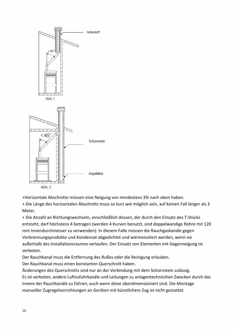
10
+Horizontale Abschnitte müssen eine Neigung von mindestens 3% nach oben haben.+ Die Länge des horizontalen Abschnitts muss so kurz wie möglich sein, auf keinen Fall länger als 3Meter.+ Die Anzahl an Richtungswechseln, einschließlich dessen, der durch den Einsatz des T-Stücksentsteht, darf höchstens 4 betragen (werden 4 Kurven benutzt, sind doppelwandige Rohre mit 120mm Innendurchmesser zu verwenden). In diesem Falle müssen die Rauchgaskanäle gegenVerbrennungsprodukte und Kondensat abgedichtet und wärmeisoliert werden, wenn sieaußerhalb des Installationsraumes verlaufen. Der Einsatz von Elementen mit Gegenneigung istverboten.Der Rauchkanal muss die Entfernung des Rußes oder die Reinigung erlauben.Der Rauchkanal muss einen konstanten Querschnitt haben.Änderungen des Querschnitts sind nur an der Verbindung mit dem Schornstein zulässig.Es ist verboten, andere Luftzufuhrkanäle und Leitungen zu anlagentechnischen Zwecken durch dasInnere der Rauchkanäle zu führen, auch wenn diese überdimensioniert sind. Die Montagemanueller Zugregelvorrichtungen an Geräten mit künstlichem Zug ist nicht gestattet.
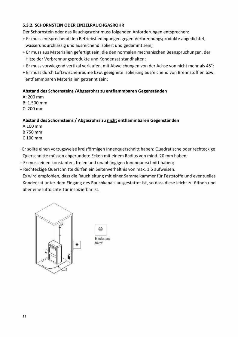
11
5.3.2. SCHORNSTEIN ODER EINZELRAUCHGASROHRDer Schornstein oder das Rauchgasrohr muss folgenden Anforderungen entsprechen:+ Er muss entsprechend den Betriebsbedingungen gegen Verbrennungsprodukte abgedichtet,wasserundurchlässig und ausreichend isoliert und gedämmt sein;
+ Er muss aus Materialien gefertigt sein, die den normalen mechanischen Beanspruchungen, derHitze der Verbrennungsprodukte und Kondensat standhalten;
+ Er muss vorwiegend vertikal verlaufen, mit Abweichungen von der Achse von nicht mehr als 45°;+ Er muss durch Luftzwischenräume bzw. geeignete Isolierung ausreichend von Brennstoff en bzw.entflammbaren Materialien getrennt sein;
Abstand des Schornsteins /Abgasrohrs zu entflammbaren GegenständenA: 200 mmB: 1.500 mmC: 200 mm
Abstand des Schornsteins / Abgasrohrs zu nicht entflammbaren GegenständenA 100mmB 750mmC 100 mm
+Er sollte einen vorzugsweise kreisförmigen Innenquerschnitt haben: Quadratische oder rechteckigeQuerschnitte müssen abgerundete Ecken mit einem Radius von mind. 20 mm haben;
+ Er muss einen konstanten, freien und unabhängigen Innenquerschnitt haben;+ Rechteckige Querschnitte dürfen ein Seitenverhältnis von max. 1,5 aufweisen.Es wird empfohlen, dass die Rauchleitung mit einer Sammelkammer für Feststoffe und eventuellesKondensat unter dem Eingang des Rauchkanals ausgestattet ist, so dass diese leicht zu öffnen undüber eine luftdichte Tür inspizierbar ist.

12

13

14
Anschluss des Gerätes an den Schornstein und Abzug der Verbrennungsprodukte:Der Schornstein darf nur die Rauchgase aus einem einzigenWärmeerzeuger aufnehmen.Der direkte Auslass in umschlossenen Räumen ist verboten, auch wenn diese nach oben offen sind.Der direkte Auslass der Verbrennungsprodukte muss über das Dach erfolgen, die Rauchgasleitungmuss die im Abschnitt "Schornstein oder Einzelrauchgasrohr" beschriebenen Eigenschaftenaufweisen.
5.4. ANSCHLUSS AN ÄUSSERE ZULUFTLEITUNGENUm einen einwandfreien Betrieb zu gewährleisten, muss das Gerät über die nötige Zuluft verfügen,und zwar über Außenluftzuleitungen. Die Zuluftleitungen müssen den folgenden Anforderungenentsprechen:+ Freier Gesamtquerschnitt von mindestens 80 cm2.+ Zuluftleitungen müssen mit Gittern, Maschendraht oder geeigneten Schutzvorrichtungengeschützt sein, die jedoch den oben genannten Mindestquerschnitt nicht verringern dürfen;außerdem sind sie so anzubringen, dass sie möglichst nicht verstopfen können. Wenn dieVerbrennungsluft direkt von Außen mittels eines Rohrs abgeleitet wird, muss außen ein Bogennach unten oder eine Windschutzvorrichtung montiert werden und es dürfen keinerlei Gitter oderähnliches angebracht werden (es wird empfohlen, die Luftzuführung direkt mit demInstallationsraum zu verbinden, auch wenn die Luft von außen über ein Rohr zugeführtwird).Die Luftzufuhr kann auch über einen angrenzenden Raum erfolgen. Dabei ist darauf zu Achten,dass die Zufuhr frei über permanente Öffnungen, nach außen, erfolgt. Der an den

15
Installationsraum angrenzende Raum darf gegenüber der Außenumgebung keinen Unterdruckbekommen, der durch den entgegengesetzter Zug hervorgerufen werden kann, wenn in diesemRaum ein anderes Gerät oder eine Absaugvorrichtung betrieben wird. Im angrenzenden Raummüssen die permanenten Öffnungen den oben genannten Anforderungen entsprechen. Derangrenzende Raum darf nicht als Garage oder Lager für brennbare Stoffe benutzt werden und vorallem nicht für Tätigkeiten, die Brandgefahr mit sich bringen.
Das Ansaugen der Frischluft für die Verbrennung erfolgt durch den Rauchgasventilator. Dieentstehenden Ansauggeräusche sind normale Betriebsgeräusche des Ofens und erfolgen mitunterschiedlicher Lautstärke je nach Kaminabzug, Heizungsstärke und Verschmutzung desAbzugsrohrs. Diese Geräusche sind kein Reklamationsgrund.
Der Abstand zwischen Wand und Ofen (in mm)

16
Elektrischer Anschluss:Der Ofen ist mit einem ca. 2m langen Kabel mit Stecker ausgestattet. Das geerdete elektrischeKabel sollte an einer Standardsteckdosemit 230V, 50Hz angeschlossen werden. Während desBetriebs hat der Ofen einen Verbrauch von 100 Watt / Stunde. Während der Anzündphase (ca. 8-10Minuten) verbraucht der Ofen ca. 350Watt. Achten Sie darauf, dass das Stromkabel nicht unterdem Gerät eingeklemmt ist und keine heiße Oberfläche oder scharfen Kantenberührt.
6 - BedienungsanleitungHinweise:- Alle nationalen, lokalen Vorschriften und Europäische Normenmüssen bei Betrieb des Gerätes
eingehalten werden.- Achtung: Fassen Sie niemals die heißen Oberflächen des Ofens während des Betriebesohne
Schutzausrüstung (Hitzeschutzhandschuhe) an. Der Ofen wird mit einem Extra Griff für dasÖffnen und Schließen der Türe geliefert. Benützen Sie diesen zum Öffnen der Türe! SiehePunkt 8 -Wartung und Pflege.
- Brennstoffe: Der Kaminofen ist zum Verbrennen von Holzpellets gebaut. Wir empfehlen dieVerwendung von Pellets, die den Qualitäten der Norm ISO 17225-2 entsprechen. Das sindzum Beispiel Pellets für mit dem SiegelENplus-A1.
- Folgende Stoffe dürfen nach dem Bundesemissionsschutzgesetz nicht verbrannt werden:Feuchtes oder mit Holzschutzmittel behandeltes Holz, Feinhackschnitzel, Papier und Pappe,Rinden oder Spanplattenabfälle, Kunststoff oder sonstigeAbfälle.
- Stellen Sie sicher, dass der Ofen eine ausreichende Verbrennungsluftzufuhr hat, sowie einesichere Abführung der Abgase.
- Die Feuerstätte darf in keiner Weise baulich verändert werden. Jegliche Änderung kanngefährliche Verletzungen und Brand zur Folge haben. Jeglicher Gewährleistungsansprucherlischt.
- Verwenden Sie ausschließlich vom Hersteller empfohlene Ersatzteile.
6.1. InbetriebnahmeAchten Sie darauf, dass keine Aufkleber oder Verpackungsreste sich am Ofen oder im Ofenbefinden. Entfernen Sie diese ggf. und reinigen den Ofen mit einem trockenen, weichen Tuch.Eventuelle Farbgerüche können bei der Erstbefeuerung auftreten, sind aber nichtgesundheitsschädlich und verflüchtigen sich sehr schnell. Der Pelletofen ist eine Zeitbrandstätteund kann nicht ununterbrochen betrieben werden.
Hinweis: Wenn der neue Ofen zum ersten Mal in Betrieb genommen wird, ist es notwendig vorhereine Handvoll Pellets von Hand in die Brennschale zu legen.Legen Sie die Holzpellets in den Ladebehälter und schließen Sie erst danach das Netzkabel an.Folgen Sie nun den Anweisungen in Abschnitt 2 „Start und Betrieb“
ACHTUNG: Bei der Erstbefeuerung und nach längerem Nichtbenutzen darf der Ofenmaximal in Stufe 3 betrieben werden. Zu hohe Temperatur kann bei derErstbefeuerung zu Schäden im Brennraum führen. Nach ca. 2 Stunden können Sie

17
den Ofen normal betreiben.Achten Sie darauf, nach längerer Betriebsunterbrechung alle Abgasrohre und den Schornstein aufDurchlässigkeit zu prüfen.
6.2. Start und BetriebBitte bedienen Sie den Ofen wie folgt (siehe Aufbau des Ofens und den elektrischen Plan):Prüfen Sie vor jeder Inbetriebnahme den Aschebehälter, und die Brennschale aufVerschmutzungen. Entfernen Sie diese uns setzten Sie all Teile korrekt ein bevor Sie den Ofen inBetrieb nehmen.
An-/ und AusschalterDas Ein- und Ausschalten des Gerätes wird über den ON-/OFF- Schalter durchgeführt
Beim ersten Einschalten sehen Sie auf dem Dispaly: CLAENING“, da das Gerät gereinigt werdenmuss.
Die Meldung „Cleaning“ wird für 20 Sekunden angezeigt, wenn die Brennschalegereinigt werdenmuss.

18
Kurzanleitung Funktionen

19
↓→
Einschalten /AusschaltenMit dem ON/OFF Schalter wird der Ofenein-und Ausgeschaltet
Nach dem der Knopf gedrückt wurdeerscheint auf dem Display "CLEANING"Der Brenntopf wird gereinigt.
Die Anzündphase dauert 5-15 Minuten.Diese Zeit wird benötigt, um die Pellets aufdie notwendige Temperatur zu erhitzen. DieAnzündphase wird erst mit„CLEANING“ dannmit„FEEDING“angezeigt:
→↓
Wir der Knopf noch einmalgedrückt, wird der Ofenausgeschaltet.Folgende Nachricht erscheint auf demDisplay: Während der Anzeige ‘FEEDING’ werden die
Pellets mit Hilfe der Einzugsschnecke in denBrenntopf befördert. Danach erscheint dieAnzeige “LIGHTNING”. Diese Phase bleibt solange aktiv bis der Rauch die gewünschteTemperatur erreicht.
←→↓→
Wenn die Te peratur im Ofen weitgenug abgesunken ist, erscheint diefolgende Anzeige:' GOODBYE’
Nach dem Anzünden “LIGHTNING” dauertes ein paar Minuten bis die Flamme sichstabilisiert hat. Auf der Anzeige erscheint:‘STABILIZATION” diese Anzeige erlischt
↑nach wenigen Minuten, sobald der Ofennormal arbeitet.
VORSICHT !!Während der Ausschaltphase “SWITCHING OFF” wird der Ofen abgekühlt. Während dieserPhase darf der Ofen nicht wieder gestartet werden. Sie müssen warten bis die Anzeigeerlischt.
→
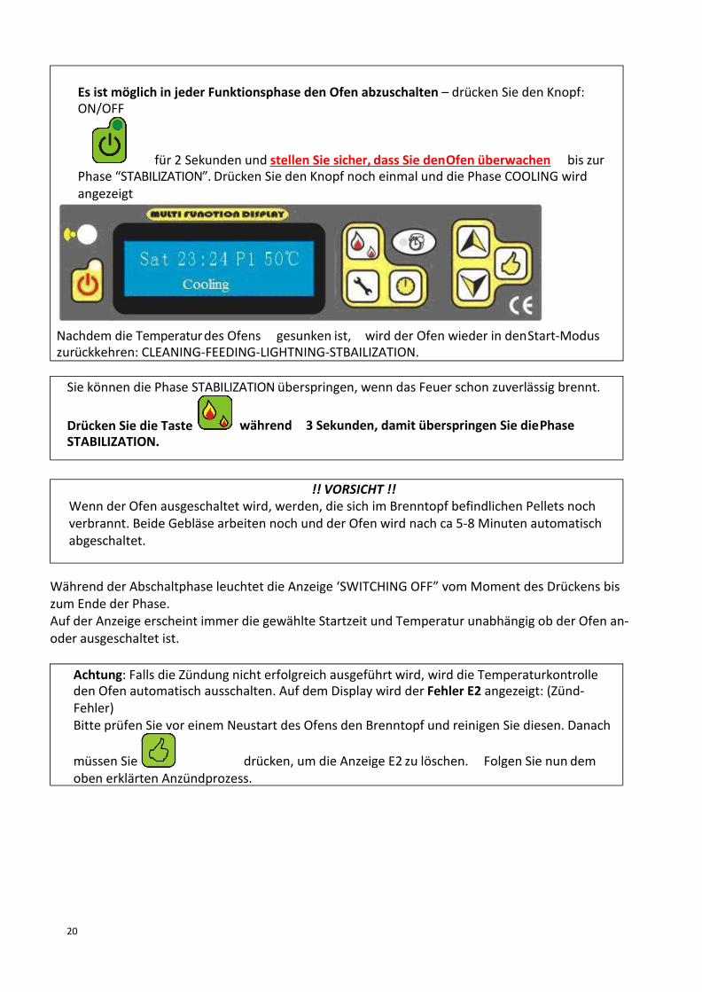
20
während 3 Sekunden, damit überspringen Sie diePhaseDrücken Sie die TasteSTABILIZATION.
Sie können die Phase STABILIZATION überspringen, wenn das Feuer schon zuverlässig brennt.
!! VORSICHT !!Wenn der Ofen ausgeschaltet wird, werden, die sich im Brenntopf befindlichen Pellets nochverbrannt. Beide Gebläse arbeiten noch und der Ofen wird nach ca 5-8 Minuten automatischabgeschaltet.
oben erklärten Anzündprozess.drücken, um die Anzeige E2 zu löschen. Folgen Sie nun demmüssen Sie
Achtung: Falls die Zündung nicht erfolgreich ausgeführt wird, wird die Temperaturkontrolleden Ofen automatisch ausschalten. Auf dem Display wird der Fehler E2 angezeigt: (Zünd-Fehler)Bitte prüfen Sie vor einem Neustart des Ofens den Brenntopf und reinigen Sie diesen. Danach
Es ist möglich in jeder Funktionsphase den Ofen abzuschalten – drücken Sie den Knopf:ON/OFF
für 2 Sekunden und stellen Sie sicher, dass Sie denOfen überwachen bis zurPhase “STABILIZATION”. Drücken Sie den Knopf noch einmal und die Phase COOLING wirdangezeigt
Nachdem die Temperaturdes Ofens gesunken ist, wird der Ofen wieder in denStart-Moduszurückkehren: CLEANING-FEEDING-LIGHTNING-STBAILIZATION.
Während der Abschaltphase leuchtet die Anzeige ‘SWITCHING OFF” vomMoment des Drückens biszum Ende der Phase.Auf der Anzeige erscheint immer die gewählte Startzeit und Temperatur unabhängig ob der Ofen an-oder ausgeschaltet ist.
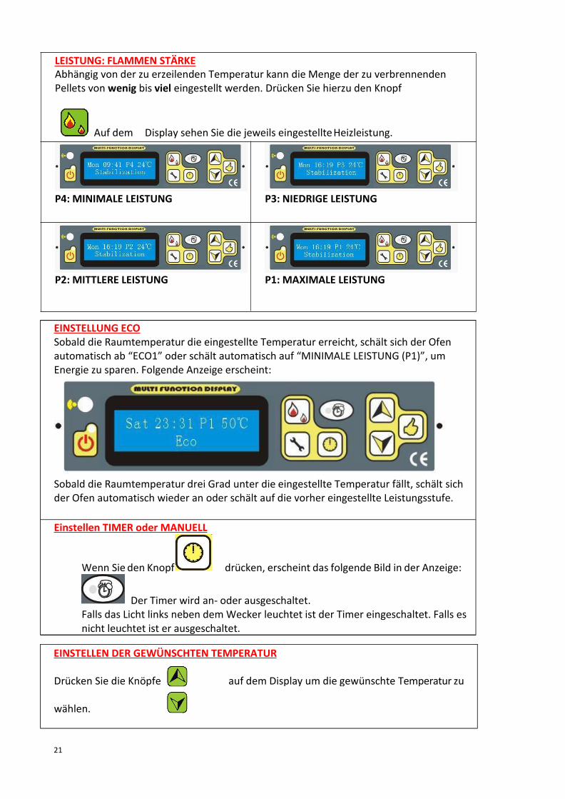
21
wählen.
auf dem Display um die gewünschte Temperatur zuDrücken Sie die Knöpfe
EINSTELLEN DER GEWÜNSCHTEN TEMPERATUR
LEISTUNG: FLAMMEN STÄRKEAbhängig von der zu erzeilenden Temperatur kann die Menge der zu verbrennendenPellets von wenig bis viel eingestellt werden. Drücken Sie hierzu den Knopf
Auf dem Display sehen Sie die jeweils eingestellteHeizleistung.
P4: MINIMALE LEISTUNG P3: NIEDRIGE LEISTUNG
P2: MITTLERE LEISTUNG P1: MAXIMALE LEISTUNG
EINSTELLUNG ECOSobald die Raumtemperatur die eingestellte Temperatur erreicht, schält sich der Ofenautomatisch ab “ECO1” oder schält automatisch auf “MINIMALE LEISTUNG (P1)”, umEnergie zu sparen. Folgende Anzeige erscheint:
Sobald die Raumtemperatur drei Grad unter die eingestellte Temperatur fällt, schält sichder Ofen automatisch wieder an oder schält auf die vorher eingestellte Leistungsstufe.
Einstellen TIMER oder MANUELL
Wenn Sie den Knopf drücken, erscheint das folgende Bild in der Anzeige:
Der Timer wird an- oder ausgeschaltet.Falls das Licht links neben demWecker leuchtet ist der Timer eingeschaltet. Falls esnicht leuchtet ist er ausgeschaltet.

22
Einstellen der Raumtemperatur, Abgastemperatur (Rauch) und Sicherheits- Temperatur
(unter dem Füllschacht) durch drücken des Knopfes:
(R) zeigt die Raumtemperatur.(S) zeigt die Abgastemperatur(P) Zeigt die Sicherheits-Temperatur
Beispiel:
Bedeutet: die Raumtemperatur beträgt 13 Grad.

23
Kurzanleitung Einstellungen

24
ücken
t 0.
Einstellung Abgasgebläse und Warmluftgebläse
Taste 2 Sekunden drücken, dann erscheint im Display:
S= Abgasgebläse F=Warmluftgebläse
Auf drücken, um zwischen “S ” und “F ”zu wechseln. dr , umdie Geschwindigkeit der Gebläse anzupassen.Beide Gebläse können von -20 bis +20 eingestellt werden. DieWerkseinstellung is
Drücken, um die Einstellung zu speichern .Dann zu P2, P3, P4, gehen:
Nach P4 kommt P5: Einstellung der Geschwindigkeit des Abgasgebläses während derReinigung „CLEANING“. Einstellbar von -20 bis + 20.P6: Einstellung der Geschwindigkeit des Abgasgebläses für den Anzündvorgang , diePhasen “FEEDING”, “LIGHTNING” und ein paar Minuten der Phase “STABILIZATION”.Einstellbar von -20 bis + 20.

25
n vo
, dann erscheint:Drücken von
Einstellung der ersten Einfüllmenge
Zum nächsten Punkt wechseln.
bestätigen.die korrekten Daten auswählen und mitDann mit
eingestellt werden.Tag,Woche, Datum und Zeit kann durch drücken von
zum Einstellen der Zeit:Drücken von
Einstellung UHR
FTF= FRIST TIME FEEDING (Erste Füllmenge)75*2 S bedeutet 75x2 =150 Sekunden Dauer der Einfüllung. Diese kanndurch Drücke neingestellt werden in Schritten von 75Sekunden.

26
Oben im Display sehen Sie jeweils den Tag der programmiert wird, die Stunde unddie Funktion (ON / OFF)Unten im Display wird die eingestellte Zeit gezeigt.
Die kleinenBalken bedeuten AUS (OFF), die großen bedeuten EIN (ON)
um die Anfangs- und die Endzeit einzustellenDann drücken Sie
drücken und dann den Wochentag auswählen:Sie können
drücken, dann können Sie wie folgt die EinstellungenWenn Sievornehmen:
Mit dieser Funktion kann die Betriebszeit des Ofens für die ganze Woche eingestelltwerden. Sie können für jeden Wochentag die Anfangs-und die Endzeit bestimmen.
in die nächste Einstellung: Die folgende AnzeigeDrücken vonerscheint:
Einstellung TIMER
Einstellung REINIGUNG (CLEANING)Sie können die Intervalle der Reinigung des Brenntopfs während der Betriebs alle “XMinuten” für „YSekunden“ mit einstellen.
Zum Beispiel: alle 30 Minuten für 15 Sekunden:
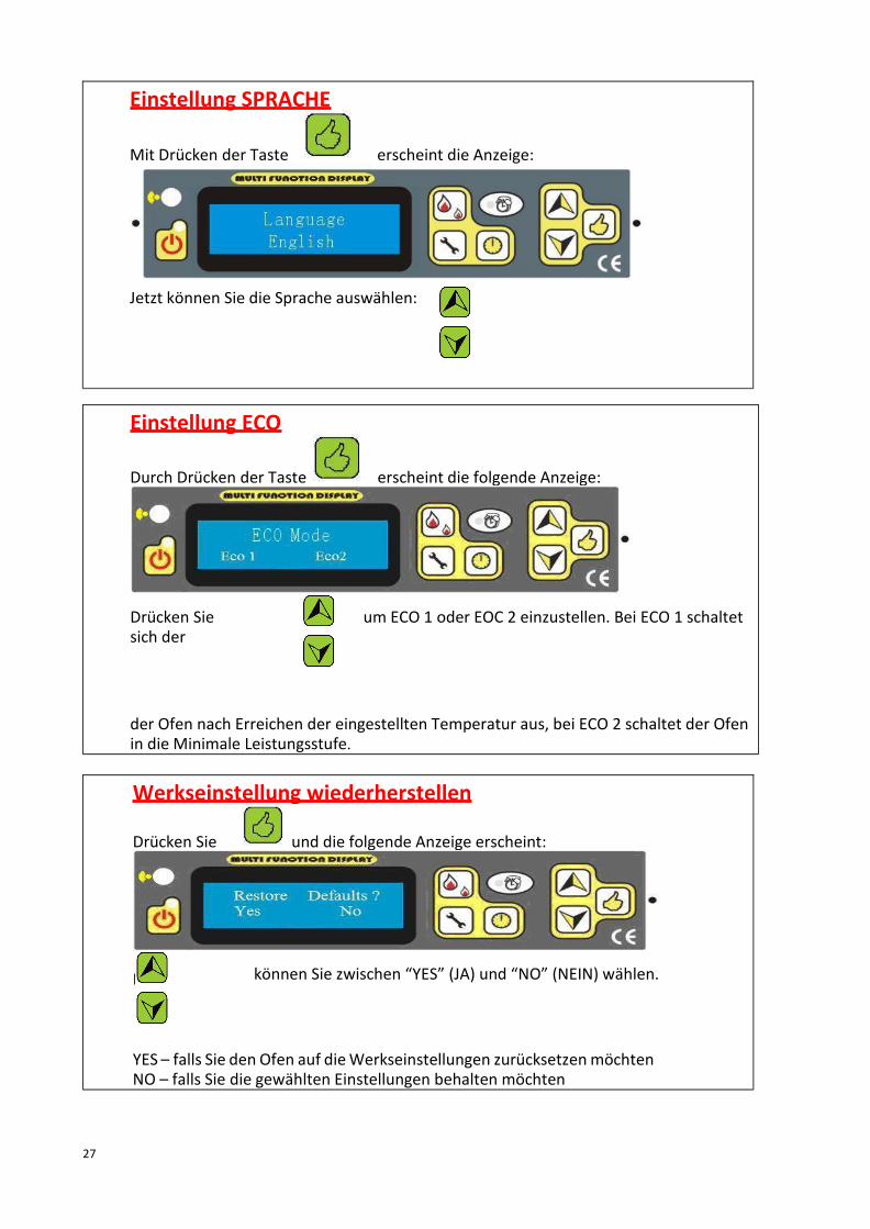
27
Mit
der Ofen nach Erreichen der eingestellten Temperatur aus, bei ECO 2 schaltet der Ofenin die Minimale Leistungsstufe.
um ECO 1 oder EOC 2 einzustellen. Bei ECO 1 schaltetDrücken Siesich der
erscheint die folgende Anzeige:Durch Drücken der Taste
Einstellung ECO
YES – falls Sie den Ofen auf dieWerkseinstellungen zurücksetzenmöchtenNO – falls Sie die gewählten Einstellungen behalten möchten
können Sie zwischen “YES” (JA) und “NO” (NEIN) wählen.
und die folgende Anzeige erscheint:Drücken Sie
Werkseinstellung wiederherstellen
Jetzt können Sie die Sprache auswählen:
erscheint die Anzeige:Mit Drücken der Taste
Einstellung SPRACHE

28
Mit Drücken der Taste können Sie die Programmierung jederzeitverlassen.
6.3. Fehlermeldungen
E1: Der Ofen stellt sich automatisch ab, dadie Abgastemperatur unter 40-45 Gradgefallen ist.
Gründe:
1. Kein Brennstoff im Brenntopf.2. Einzugsschneckenmotor defekt, dieSchnecke befördert keine Pelletsmehr.
E2: Fehler beimAnzündprozess
Gründe:1. Schlacke in der Brennschale.2. Brennschale nicht korrekteingesetzt.3. Sicherheitsschalter für die
Abgastemperatur istdefekt4. Zünder defekt
E3: Erdbeben während der Betriebs – nurfür Japan
E4: Temperatursensor hat ein Problem.1. Nicht angeschlossen oder2. Wassertemperatur ist zu hoch (nurfür
Öfen mit heißemWasser)
E5: Probleme des Vakuum-SchaltersGründe:1. Türe ist nicht korrektgeschlossen2. Abgasgebläse funktioniert nicht3. Ofen ist nicht dicht oder dasAbgasrohrist verstopft.
E6: Temperatursensor unter dem Pellet-Behälter hat ein ProblemGründe:1.Die Sicherung ist defekt,2. Die Temperatur ist zu hoch, der Ofenarbeitet nicht korrekt
E7: Der Betrieb wurde durch eineUnterbrechung der Stromversorgungunterbrochen.
E8: Der Ofen muss gereinigt werden.
Wenn das Problem behoben ist, können Sie drücken, um die Fehlermeldung zulöschen
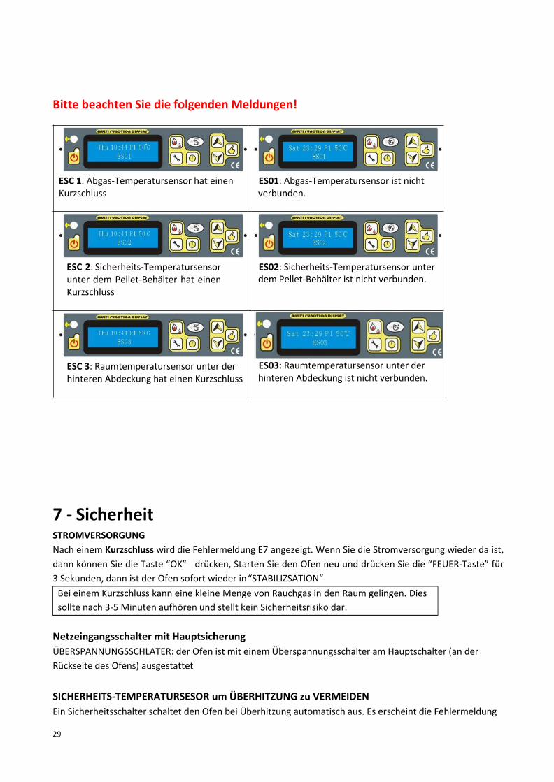
29
Bitte beachten Sie die folgenden Meldungen!
ESC 1: Abgas-Temperatursensor hat einenKurzschluss
ES01: Abgas-Temperatursensor ist nichtverbunden.
ESC 2: Sicherheits-Temperatursensorunter dem Pellet-Behälter hat einenKurzschluss
ES02: Sicherheits-Temperatursensor unterdem Pellet-Behälter ist nicht verbunden.
ESC 3: Raumtemperatursensor unter derhinteren Abdeckung hat einen Kurzschluss
ES03: Raumtemperatursensor unter derhinteren Abdeckung ist nicht verbunden.
7 - SicherheitSTROMVERSORGUNGNach einem Kurzschluss wird die Fehlermeldung E7 angezeigt. Wenn Sie die Stromversorgung wieder da ist,dann können Sie die Taste “OK” drücken, Starten Sie den Ofen neu und drücken Sie die “FEUER-Taste” für3 Sekunden, dann ist der Ofen sofort wieder in“STABILIZSATION“Bei einem Kurzschluss kann eine kleine Menge von Rauchgas in den Raum gelingen. Diessollte nach 3-5 Minuten aufhören und stellt kein Sicherheitsrisiko dar.
Netzeingangsschalter mit HauptsicherungÜBERSPANNUNGSSCHLATER: der Ofen ist mit einem Überspannungsschalter am Hauptschalter (an derRückseite des Ofens) ausgestattet
SICHERHEITS-TEMPERATURSESOR um ÜBERHITZUNG zu VERMEIDENEin Sicherheitsschalter schaltet den Ofen bei Überhitzung automatisch aus. Es erscheint die Fehlermeldung

30
Achtung: Ziehen Sie bitte vor dem Reinigen des Ofens das Netzkabel und lassenSie den Ofen abkühlen.
Achten Sie darauf, während der Montage und Installation keine Gegenständewie z.B. Schrauben in den Pellet-Behälter fallen zu lassen. Diese könnten dieEinzugsschnecke blockieren und den Ofen dadurch beschädigen.
Achten Sie darauf, das Gerät regelmäßig zu reinigen. Verunreinigungenvermindern das Heizergebnis. Bei Nicht Beachtung erlischt derGewährleistungsanspruch.
E6. Der Ofen kühlt dann ab. Falls sich noch Pellets in der Brennkammer beinfinden, werden diese vorhernoch verbrannt. Es werden jedoch keine neuen Pellets nachgefüllt. Nachdem Sie die “OK” Taste gedrückthaben wird der Ofen wieder gestartet. Falls es keine automatische Neu-Zündung gibt, wird der kompletteAnzündprozess von Vorne gestartet.VORSICHT: Falls der Ofen überhitzt muss der Ofen in jedem Fall gereinigt werden unddas Programm CLEANING durchlaufen werden.
ABGAS TMERPERATURSENSOR:Wenn die Abgastemperatur unter die Minimum Temperatur von 40-45 Grad sinkt, wird der Ofenautomatisch abgeschaltet. Falls das Vorheizen zu langsam ist, wird dieser Vorgang auch gestartet.
8 - Wartung und Pflege
WARTUNGMindestens zweimal im Jahr sollte der Ofen und die Abgasrohre gründlich überprüft und gereinigtwerden. Dazu empfiehlt sich ein weicher Lappen für die lackgeschützten Teile. Säure-oderLösungsmittelhaltige Reiniger dürfen nicht verwendet werden.Vor jedem Start sollte der Brenntopf auf grobe Verunreinigungen (z.B. Durch schlechte PelletQualität) geprüft werden.Die jährliche Kamin-Inspektion durch den Schornsteinfeger bietet sich an, um die Rauchrohre zudemontieren und Ruß zu entfernen. In diesem Zuge sollte auch der Abgasgebläsekasten aufVerbrennungsrückstände untersucht und ggf. gereinigt werden.
Manche Pellet Sorten produzieren mehr Asche und Schlacke als andere. Daher ist die Häufigkeitder Reinigung vom verwendeten Typ der Pellets und deren Qualität abhängig. Ein hoherFeuchtigkeitsgehalt, Asche, Dreck und Schlacke können das Reinigungsintervall auf das zweifacheerhöhen. Wir möchten deshalb noch einmal darauf hinweisen, dass Sie nur getestete Pellets vonNamhaften Herstellern als Brennstoff verwenden.

31
Falls Sie den Ofen ständig benützen, sollten Sie diesen 2x pro Woche für 24Stunden ausschalten, um den Brenntopf zu reinigen.
Extra GriffIm Lieferumfang befindet sich ein Extra-Griff für das Öffnen und Schließen der Türe. Bitte nützenSie den Griff auch zum Reinigen desBrenntopfs und Lösen der Pellets im Pellet-Behälter fallsdiese an den Seiten kleben
Asche als DüngerIm Holz befinden sich ca 1-2% Mineralstoffe die im Brenntopf als Asche übrig bleiben. Diese Ascheist ein natürliches Produkt und eignet sich optimal als Dünger. Bitte beachten Sie, dass die Ascheerst lagern sollte und vor Gebrauch mit Wasser vermischt werden sollte.Vorsicht: in der Asche können sich auch noch Reste nichtverbrannter Holzpellets befinden. Bitte Sieben Sie diese aus undentsorgen Sie diese in Metallbehältern.
Reinigung der Brennschale
WICHTIG: Säubern Sie den Brenntopf täglich! Stellen Sie sicher, dass keine Asche oder Schlacke dieÖffnungen für die Pellet-Zufuhr oder die Lüftung verstopfen. Der Brenntopf kann einfach aus dem Ofengenommen und gereinigt werden. Saugen Sie nach Entnehmen des Aschebehälters den komplettenInnenraum des Ofens mit einem Aschesauger aus.
VORSICHT: Reinigen Sie den Ofen nur, wenn er vollständig abgekühlt ist. Dann sind alle glühendenPellet-Reste erloschen.WICHTIG: Prüfen Sie nach der Reinigung ob der Brenntopf korrekt eingesetzt wurde.
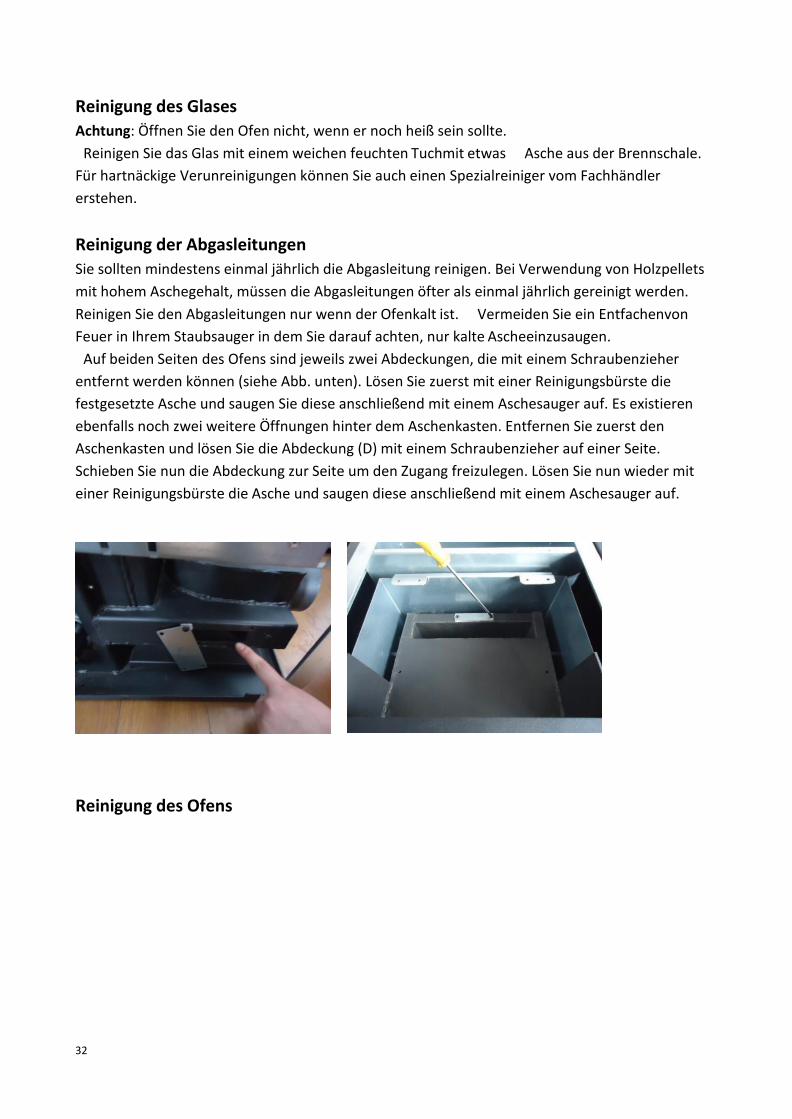
32
Reinigung des GlasesAchtung: Öffnen Sie den Ofen nicht, wenn er noch heiß sein sollte.Reinigen Sie das Glas mit einem weichen feuchten Tuchmit etwas Asche aus der Brennschale.
Für hartnäckige Verunreinigungen können Sie auch einen Spezialreiniger vom Fachhändlererstehen.
Reinigung der AbgasleitungenSie sollten mindestens einmal jährlich die Abgasleitung reinigen. Bei Verwendung von Holzpelletsmit hohem Aschegehalt, müssen die Abgasleitungen öfter als einmal jährlich gereinigt werden.Reinigen Sie den Abgasleitungen nur wenn der Ofenkalt ist. Vermeiden Sie ein EntfachenvonFeuer in Ihrem Staubsauger in dem Sie darauf achten, nur kalte Ascheeinzusaugen.Auf beiden Seiten des Ofens sind jeweils zwei Abdeckungen, die mit einem Schraubenzieher
entfernt werden können (siehe Abb. unten). Lösen Sie zuerst mit einer Reinigungsbürste diefestgesetzte Asche und saugen Sie diese anschließend mit einem Aschesauger auf. Es existierenebenfalls noch zwei weitere Öffnungen hinter dem Aschenkasten. Entfernen Sie zuerst denAschenkasten und lösen Sie die Abdeckung (D) mit einem Schraubenzieher auf einer Seite.Schieben Sie nun die Abdeckung zur Seite um den Zugang freizulegen. Lösen Sie nun wieder miteiner Reinigungsbürste die Asche und saugen diese anschließend mit einem Aschesauger auf.
Reinigung des Ofens
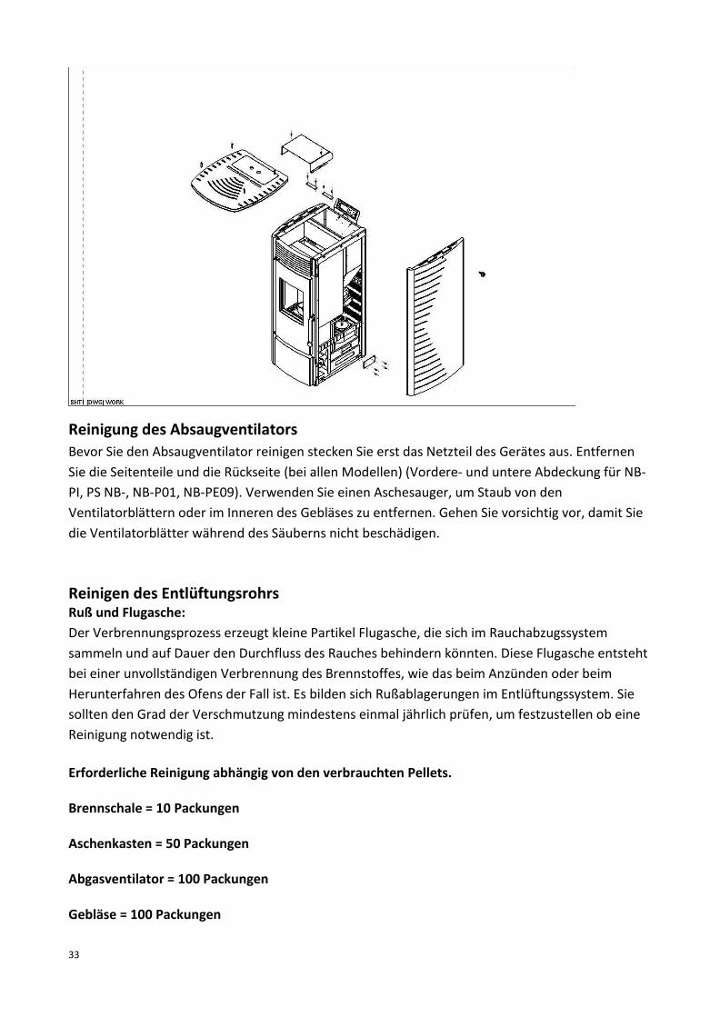
33
Reinigung des AbsaugventilatorsBevor Sie den Absaugventilator reinigen stecken Sie erst das Netzteil des Gerätes aus. EntfernenSie die Seitenteile und die Rückseite (bei allen Modellen) (Vordere- und untere Abdeckung für NB-PI, PS NB-, NB-P01, NB-PE09). Verwenden Sie einen Aschesauger, um Staub von denVentilatorblättern oder im Inneren des Gebläses zu entfernen. Gehen Sie vorsichtig vor, damit Siedie Ventilatorblätter während des Säuberns nicht beschädigen.
Reinigen des EntlüftungsrohrsRuß und Flugasche:Der Verbrennungsprozess erzeugt kleine Partikel Flugasche, die sich im Rauchabzugssystemsammeln und auf Dauer den Durchfluss des Rauches behindern könnten. Diese Flugasche entstehtbei einer unvollständigen Verbrennung des Brennstoffes, wie das beim Anzünden oder beimHerunterfahren des Ofens der Fall ist. Es bilden sich Rußablagerungen im Entlüftungssystem. Siesollten den Grad der Verschmutzung mindestens einmal jährlich prüfen, um festzustellen ob eineReinigung notwendig ist.
Erforderliche Reinigung abhängig von den verbrauchten Pellets.
Brennschale = 10 Packungen
Aschenkasten = 50 Packungen
Abgasventilator = 100 Packungen
Gebläse = 100 Packungen
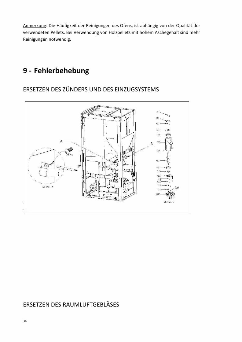
34
Anmerkung: Die Häufigkeit der Reinigungen des Ofens, ist abhängig von der Qualität derverwendeten Pellets. Bei Verwendung von Holzpellets mit hohem Aschegehalt sind mehrReinigungen notwendig.
9 - Fehlerbehebung
ERSETZEN DES ZÜNDERS UND DES EINZUGSYSTEMS
ERSETZEN DES RAUMLUFTGEBLÄSES

35
ERSETZEN DES ABGASGEBLÄSES
Allgemeine Probleme, mögliche Gründe und Lösungen.Nachdem das Problem gelöst wurde, können sie den Ofen wieder starten.
Problem Grund Lösung
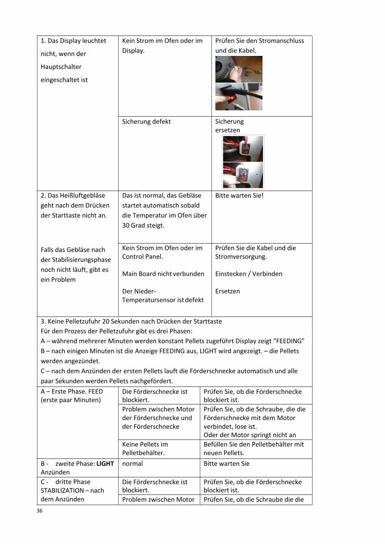
36
1. Das Display leuchtet
nicht, wenn der
Hauptschalter
eingeschaltet ist
Kein Strom im Ofen oder imDisplay.
Prüfen Sie den Stromanschlussund die Kabel.
Sicherung defekt Sicherungersetzen
2. Das Heißluftgebläsegeht nach dem Drückender Starttaste nicht an.
Falls das Gebläse nachder Stabilisierungsphasenoch nicht läuft, gibt esein Problem
Das ist normal, das Gebläsestartet automatisch sobalddie Temperatur im Ofen über30 Grad steigt.
Bitte warten Sie!
Kein Strom im Ofen oder imControl Panel.
Main Board nicht verbunden
Der Nieder-Temperatursensor ist defekt
Prüfen Sie die Kabel und dieStromversorgung.
Einstecken / Verbinden
Ersetzen
3. Keine Pelletzufuhr 20 Sekunden nach Drücken der StarttasteFür den Prozess der Pelletzufuhr gibt es drei Phasen:A – während mehrerer Minuten werden konstant Pellets zugeführt Display zeigt “FEEDING”B – nach einigen Minuten ist die Anzeige FEEDING aus, LIGHT wird angezeigt. – die Pelletswerden angezündet.C – nach dem Anzünden der ersten Pellets lauft die Förderschnecke automatisch und allepaar Sekunden werden Pellets nachgefördert.A – Erste Phase. FEED(erste paar Minuten)
Die Förderschnecke istblockiert.
Prüfen Sie, ob die Förderschneckeblockiert ist.
Problem zwischen Motorder Förderschnecke undder Förderschnecke
Prüfen Sie, ob die Schraube, die dieFörderschnecke mit demMotorverbindet, lose ist.Oder der Motor springt nicht an
Keine Pellets imPelletbehälter.
Befüllen Sie den Pelletbehälter mitneuen Pellets.
B - zweite Phase: LIGHTAnzünden
normal Bitte warten Sie
C - dritte PhaseSTABILIZATION – nachdem Anzünden
Die Förderschnecke istblockiert.
Prüfen Sie, ob die Förderschneckeblockiert ist.
Problem zwischen Motor Prüfen Sie, ob die Schraube die die
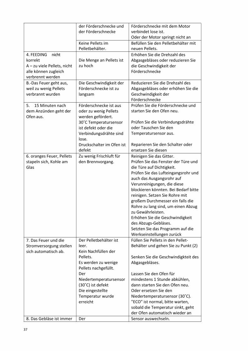
37
der Förderschnecke undder Förderschnecke
Förderschnecke mit demMotorverbindet lose ist.Oder der Motor springt nicht an
Keine Pellets imPelletbehälter.
Befüllen Sie den Pelletbehälter mitneuen Pellets.
4. FEEDING nichtkorrektA – zu viele Pellets, nichtalle können zugleichverbrennt werden
Die Menge an Pellets istzu hoch
Erhöhen Sie die Drehzahl desAbgasgebläses oder reduzieren Siedie Geschwindigkeit derFörderschnecke
B.-Das Feuer geht aus,weil zu wenig Pelletsverbrannt wurden
Die Geschwindigkeit derFörderschnecke ist zulangsam
Reduzieren Sie die Drehzahl desAbgasgebläses oder erhöhen Sie dieGeschwindigkeit derFörderschnecke
5. 15 Minuten nachdem Anzünden geht derOfen aus.
Förderschnecke ist ausoder zu wenig Pelletswerden gefördert.30˚C Temperatursensorist defekt oder dieVerbindungsdrähte sindlose.Druckschalter im Ofen istdefekt
Prüfen Sie die Förderschnecke undstarten Sie den Ofen neu.
Prüfen Sie die Verbindungsdrähteoder Tauschen Sie denTemperatursensor aus.
Reparieren Sie den Schalter oderersetzen Sie diesen
6. oranges Feuer, Pelletsstapeln sich, Kohle amGlas
Zu wenig Frischluft fürden Brennvorgang.
Reinigen Sie das Gitter.Prüfen Sie das Fenster der Türe unddie Türe auf Dichtigkeit.Prüfen Sie das Lufteingangsrohr undauch das Ausgangsrohr aufVerunreinigungen, die dieseblockieren könnten. Bei Bedarf bittereinigen. Setzen Sie Rohre mitgroßem Durchmesser ein falls dieRohre zu lang sind, um einen Abzugzu Gewährleisten.Erhöhen Sie die Geschwindigkeitdes Abzugs-Gebläses.Setzten Sie das Programm auf dieWerkseinstellungen zurück
7. Das Feuer und dieStromversorgung stellensich automatisch ab.
Der Pelletbehälter istleer.Kein Nachfüllen derPellets.Es werden zu wenigePellets nachgefüllt.DerNiedertemperatursensor(30˚C) ist defektDie eingestellteTemperatur wurdeerreicht
Füllen Sie Pellets in den Pellet-Behälter und gehen Sie zu Punkt (2)
Senken Sie die Geschwindigkteit desAbgasgebläses.
Lassen Sie den Ofen fürmindestens 1 Stunde abkühlen,dann starten Sie den Ofen neu.Oder ersetzen Sie denNiedertemperatursensor (30˚C)."ECO" ist normal, bitte warten,sobald die Temperatur sinkt, gehtder Ofen automatisch wieder an
8. Das Gebläse ist immer Der Sensor auswechseln.

38
noch an nachdem derOfen abgekühlt ist
Niedertemperatursensor(30˚C) ist defekt
9. nicht genug warmeLuft
Schlechtes BrennmaterialWarmluftgebläse ist zulangsam eingestellt oderläuft gar nicht.Wärmeaustauschstäbeoder die Zwischenräumesind verstopft /verschmutzt.
Nützen Sie die empfohlenen Pelletsmit hoher QualitätTauschen Sie das Gebläse aus(defekt) oder das Mainboard istdefektReinigen Sie dieWärmeaustauschstäbe und dieZwischenräume.
10. Display zeigt "E5" Gebläse ist blockiert
Die Türe ist offen oderdie Dichtung musserneuert werden
Schalten Sie den Ofen aus undprüfen Sie das GebläseSchließen Sie die Türe, oderersetzen Sie die Dichtung
Es gibt LecksPassen Sie die Geschwindigkeit desAbgasgebläses an, um mehr Druckim Ofen zu erzeugen.
10 - Gewährleistung
1. Es gelten die gesetzlichen Bestimmungen zurGewährleistung.2. Bei Problemen und Störungen die der Besitzer durch nicht ordnungsgemäßen Betrieb desGerätes hervorruft, erlischt derGewährleistungsanspruch.3. - Die Installation und Inbetriebnahme muss von unserem Servicetechniker SERVICRUZdurchgeführtwerden, der geschultes Personal hat.4.-Sie müssen mindestens einmal im Jahr eine Wartung bei unserem SERVICRUZ-Kundendienst anfordern.

39
11 - Schaltplan