informacion general del tren de fuerza del cat 910f
TRANSCRIPT
21/08/14 910,910E,910F,910FII,910G,910GII Compact Wheel Loader 40Y00001-UP (MACHINE)(KEBP6223 - 00) -…
1/33https://sis.cat.com/sisweb/sisweb/techdoc/techdoc_print_page.jsp?returnurl=/sisweb/sisweb/medias…
Pantalla anterior
Bienvenido: cr080dwlProducto: COMPACT WHEEL LOADERModelo: 910 COMPACT WHEEL LOADER 40YConfiguración: 910,910E,910F,910FII,910G,910GII Compact WheelLoader 40Y00001-UP (MACHINE)
Operación de Sistemas 910 WHEEL LOADER POWER TRAINNúmero de medio -SENR7987-00 Fecha de publicación -01/10/1979 Fecha de actualización -12/10/2001
Systems Operation
General Information - (910 Serial No. 40Y)
NOTE: For Specifications with illustrations, make reference to SPECIFICATIONS FOR 910 WHEEL
LOADER POWER TRAIN, Form No. SENR7986. If the Specifications in Form SENR7986 are not the same as
in the Systems Operation and the Testing and Adjusting, look at the printing date on the back cover of each book.Use the Specifications given in the book with the latest date.
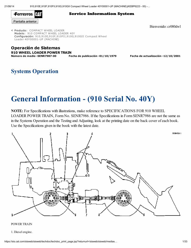
POWER TRAIN
1. Diesel engine.
21/08/14 910,910E,910F,910FII,910G,910GII Compact Wheel Loader 40Y00001-UP (MACHINE)(KEBP6223 - 00) -…
2/33https://sis.cat.com/sisweb/sisweb/techdoc/techdoc_print_page.jsp?returnurl=/sisweb/sisweb/medias…
2. Torque converter.
3. Transmission.
4. Transfer gears.
5. Final drive for the rear wheels.
6. Rear differential.
7. Drive shafts.
8. Front differential.
9. Final drives for the front wheels.
Power from diesel engine (1) is sent from the engine to torque converter (2). The output shaft of the torqueconverter sends the power to transmission (3). There are four clutches in the transmission. Three clutches are
stationary with one rotating clutch to give the machine three speeds FORWARD and one speed in REVERSE. Theselection of the desired speed is done manually by the operator but hydraulic oil, directed by the transmissionhydraulic controls, engages the proper clutch in the transmission.
Power from the transmission output shaft is sent to transfer gears (4) inside the transfer gear case. Power is thensent from the transfer gear output shaft (bottom shaft) to drive shafts (7). The drive shafts are connected to reardifferential (6) and front differential (8). Power from the differentials is then sent to final drives (5 and 9). The finaldrives turns the wheels.
Torque Converter - (910 Serial No. 40Y)
The torque converter is connected to the input end of the transmission. The torque converter is connected to the
inside of the flywheel with splines. Output torque from the converter goes in the planetary transmission through aturning clutch and/or a sun gear. Only one clutch is engaged for each speed.
The oil for the torque converter comes from the transmission pump. A relief valve controls the oil flow to theconverter. This valve is in the pressure control valve.
Restrictions in the oil cooler controls the pressure from the outlet of the torque converter.
The spider, turning housing (8), impeller (2), and drive gear for the oil pump (3) turn as a unit at engine speed.
Oil, from the hydraulic controls, goes into the converter through inlet (4). The action of the impeller is similar to apump. The flow of oil inside the converter is:
From impeller (2) to turbine (6).
From turbine (6) to stator (9).
From stator (9) back to impeller (2).
Splines make the connection between turbine (6) and output shaft (5). The stator (9) is fastened to a flange. The
21/08/14 910,910E,910F,910FII,910G,910GII Compact Wheel Loader 40Y00001-UP (MACHINE)(KEBP6223 - 00) -…
3/33https://sis.cat.com/sisweb/sisweb/techdoc/techdoc_print_page.jsp?returnurl=/sisweb/sisweb/medias…
flange is fastened to the transmission.
An outlet passage (7) in the carrier lets the oil out of the converter. The oil goes through the oil cooler to thelubrication system of the transmission.
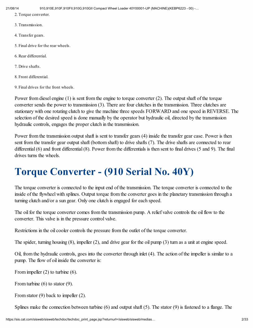
The oil flow caused by the movement of the impeller, turns the turbine and the output shaft. During normal
operation, the oil goes through the converter against a minimum of restriction, hitting each blade at a small angle.When the machine is working against a load, the speed of the turbine becomes slower, and the oil hits the blades ata more direct angle. This multiplies the torque sent to the output shaft.
TORQUE CONVERTER 1. Spider. 2. Impeller. 3. Drive gear for the pump. 4. Oil inlet. 5. Output shaft. 6. Turbine. 7. Oil outlet. 8. Turning housing. 9. Stator.AA. Drive assembly. BB. Driven assembly. CC. Stationary assembly.
The output shaft (5) of the torque converter turns the input shaft of the transmission.
Lubrication System For The Transmission - (910Serial No. 40Y)
21/08/14 910,910E,910F,910FII,910G,910GII Compact Wheel Loader 40Y00001-UP (MACHINE)(KEBP6223 - 00) -…
4/33https://sis.cat.com/sisweb/sisweb/techdoc/techdoc_print_page.jsp?returnurl=/sisweb/sisweb/medias…
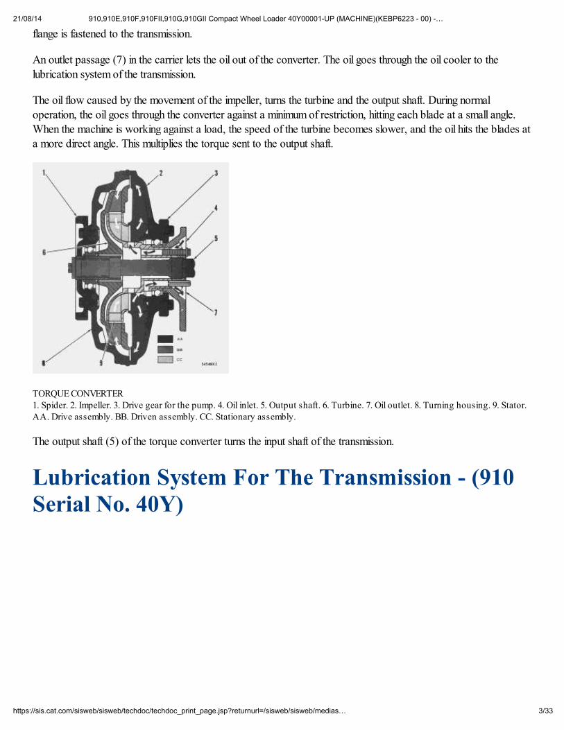
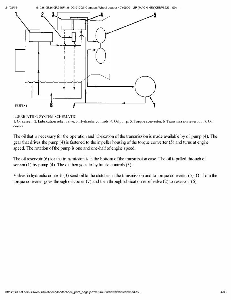
LUBRICATION SYSTEM SCHEMATIC 1. Oil screen. 2. Lubrication relief valve. 3. Hydraulic controls. 4. Oil pump. 5. Torque converter. 6. Transmission reservoir. 7. Oilcooler.
The oil that is necessary for the operation and lubrication of the transmission is made available by oil pump (4). Thegear that drives the pump (4) is fastened to the impeller housing of the torque converter (5) and turns at enginespeed. The rotation of the pump is one and one-half of engine speed.
The oil reservoir (6) for the transmission is in the bottom of the transmission case. The oil is pulled through oilscreen (1) by pump (4). The oil then goes to hydraulic controls (3).
Valves in hydraulic controls (3) send oil to the clutches in the transmission and to torque converter (5). Oil from thetorque converter goes through oil cooler (7) and then through lubrication relief valve (2) to reservoir (6).
21/08/14 910,910E,910F,910FII,910G,910GII Compact Wheel Loader 40Y00001-UP (MACHINE)(KEBP6223 - 00) -…
5/33https://sis.cat.com/sisweb/sisweb/techdoc/techdoc_print_page.jsp?returnurl=/sisweb/sisweb/medias…
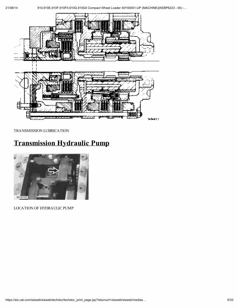
TRANSMISSION LUBRICATION
Transmission Hydraulic Pump
LOCATION OF HYDRAULIC PUMP
21/08/14 910,910E,910F,910FII,910G,910GII Compact Wheel Loader 40Y00001-UP (MACHINE)(KEBP6223 - 00) -…
6/33https://sis.cat.com/sisweb/sisweb/techdoc/techdoc_print_page.jsp?returnurl=/sisweb/sisweb/medias…
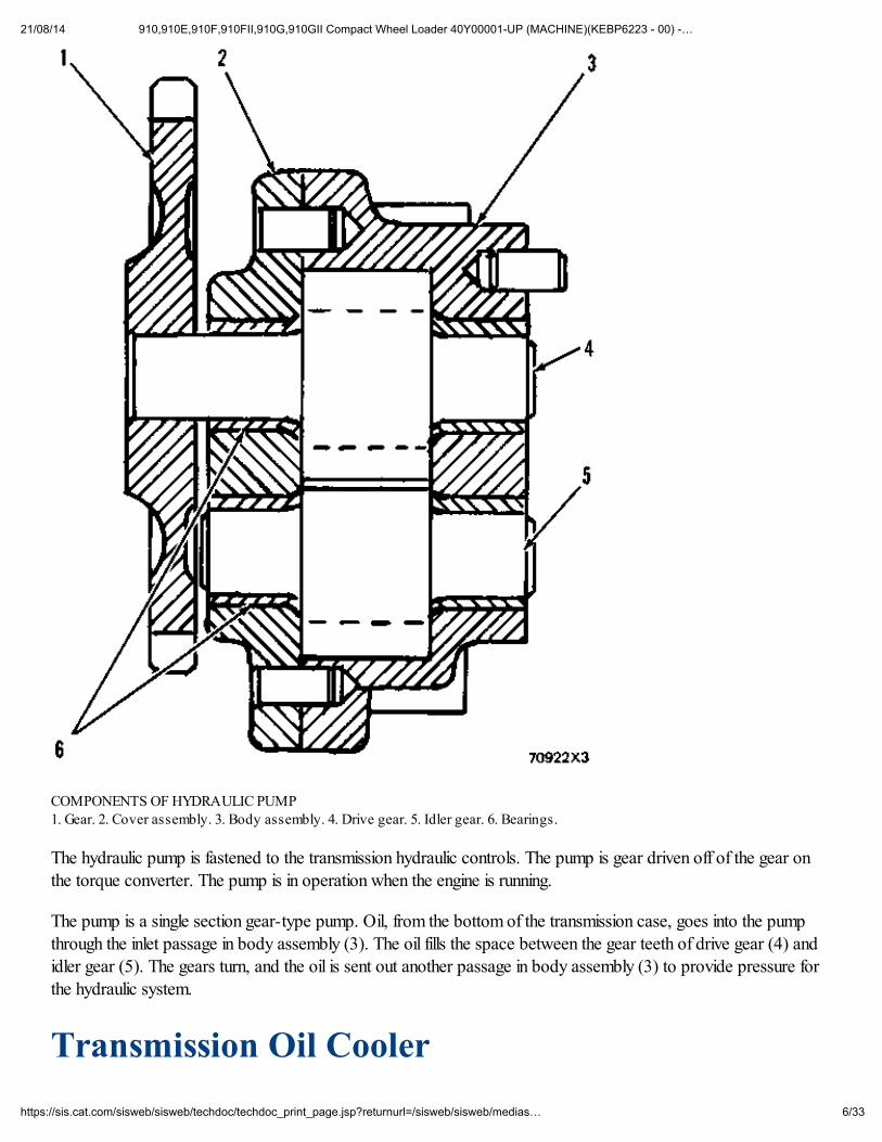
COMPONENTS OF HYDRAULIC PUMP 1. Gear. 2. Cover assembly. 3. Body assembly. 4. Drive gear. 5. Idler gear. 6. Bearings.
The hydraulic pump is fastened to the transmission hydraulic controls. The pump is gear driven off of the gear on
the torque converter. The pump is in operation when the engine is running.
The pump is a single section gear-type pump. Oil, from the bottom of the transmission case, goes into the pump
through the inlet passage in body assembly (3). The oil fills the space between the gear teeth of drive gear (4) andidler gear (5). The gears turn, and the oil is sent out another passage in body assembly (3) to provide pressure for
the hydraulic system.
Transmission Oil Cooler
21/08/14 910,910E,910F,910FII,910G,910GII Compact Wheel Loader 40Y00001-UP (MACHINE)(KEBP6223 - 00) -…
7/33https://sis.cat.com/sisweb/sisweb/techdoc/techdoc_print_page.jsp?returnurl=/sisweb/sisweb/medias…
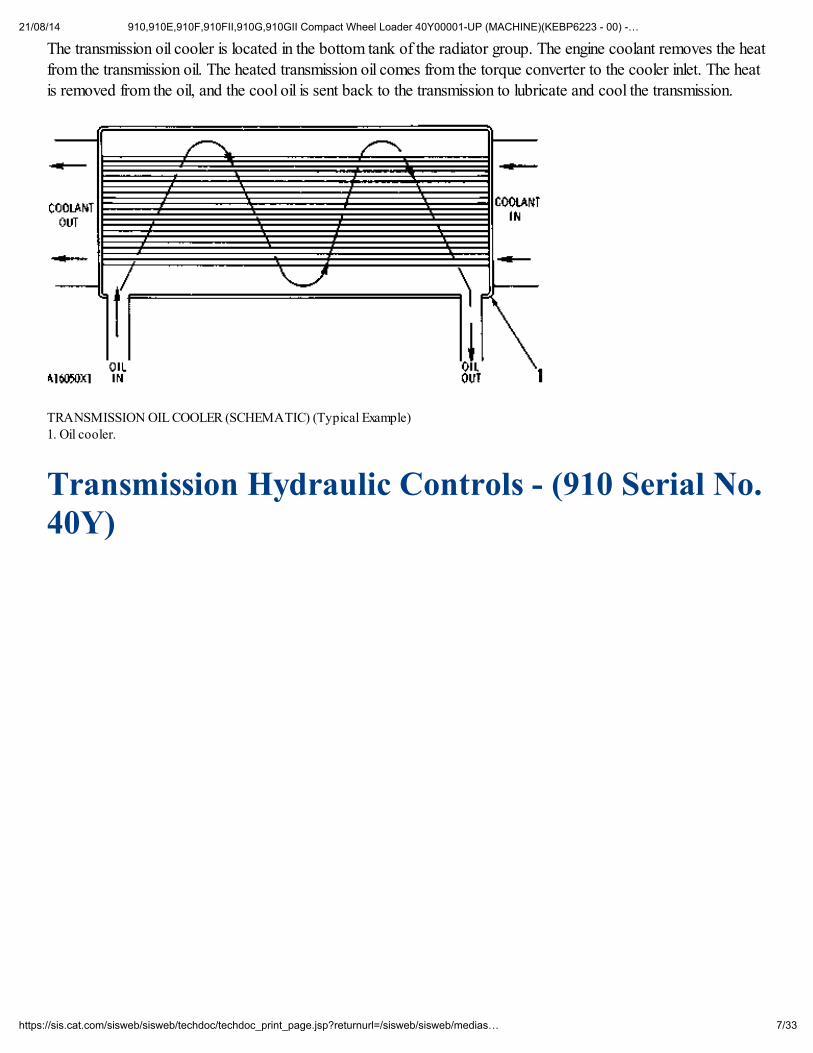
The transmission oil cooler is located in the bottom tank of the radiator group. The engine coolant removes the heat
from the transmission oil. The heated transmission oil comes from the torque converter to the cooler inlet. The heatis removed from the oil, and the cool oil is sent back to the transmission to lubricate and cool the transmission.
TRANSMISSION OIL COOLER (SCHEMATIC) (Typical Example) 1. Oil cooler.
Transmission Hydraulic Controls - (910 Serial No.40Y)
21/08/14 910,910E,910F,910FII,910G,910GII Compact Wheel Loader 40Y00001-UP (MACHINE)(KEBP6223 - 00) -…
8/33https://sis.cat.com/sisweb/sisweb/techdoc/techdoc_print_page.jsp?returnurl=/sisweb/sisweb/medias…
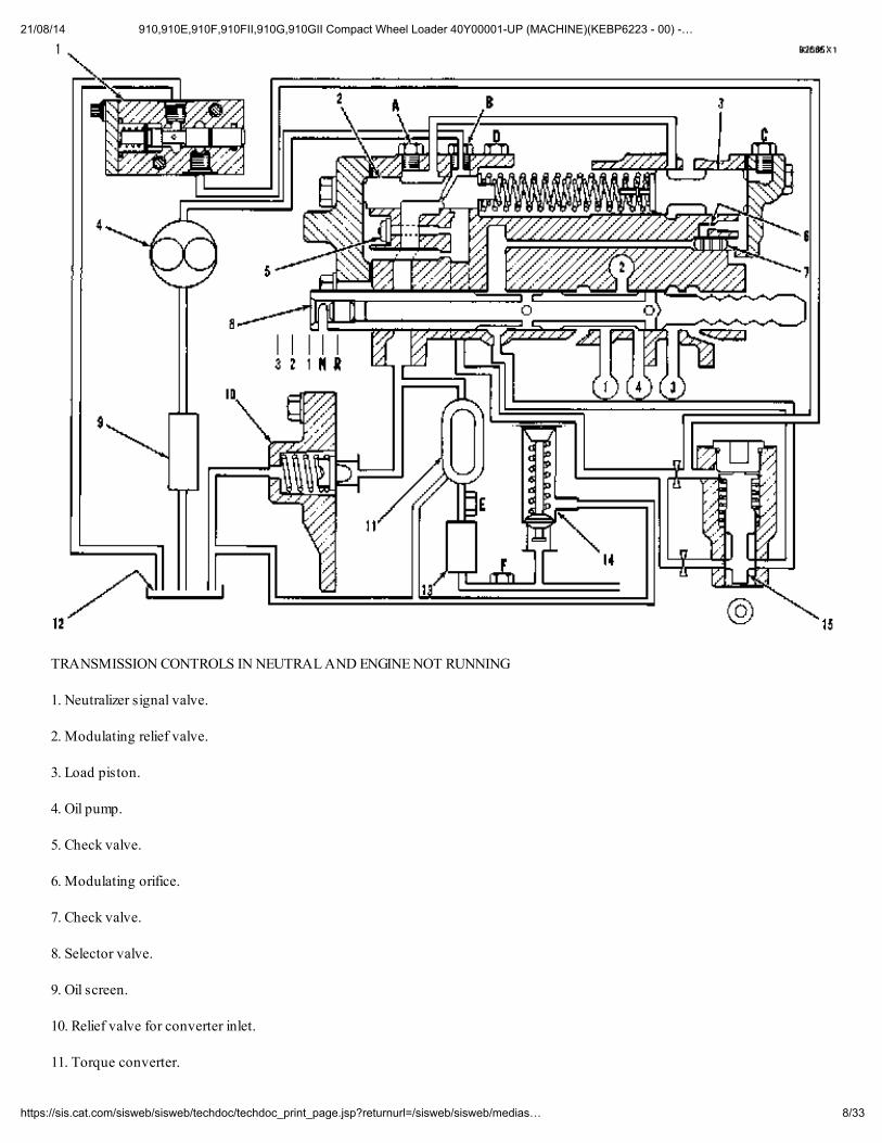
TRANSMISSION CONTROLS IN NEUTRAL AND ENGINE NOT RUNNING
1. Neutralizer signal valve.
2. Modulating relief valve.
3. Load piston.
4. Oil pump.
5. Check valve.
6. Modulating orifice.
7. Check valve.
8. Selector valve.
9. Oil screen.
10. Relief valve for converter inlet.
11. Torque converter.
21/08/14 910,910E,910F,910FII,910G,910GII Compact Wheel Loader 40Y00001-UP (MACHINE)(KEBP6223 - 00) -…
9/33https://sis.cat.com/sisweb/sisweb/techdoc/techdoc_print_page.jsp?returnurl=/sisweb/sisweb/medias…
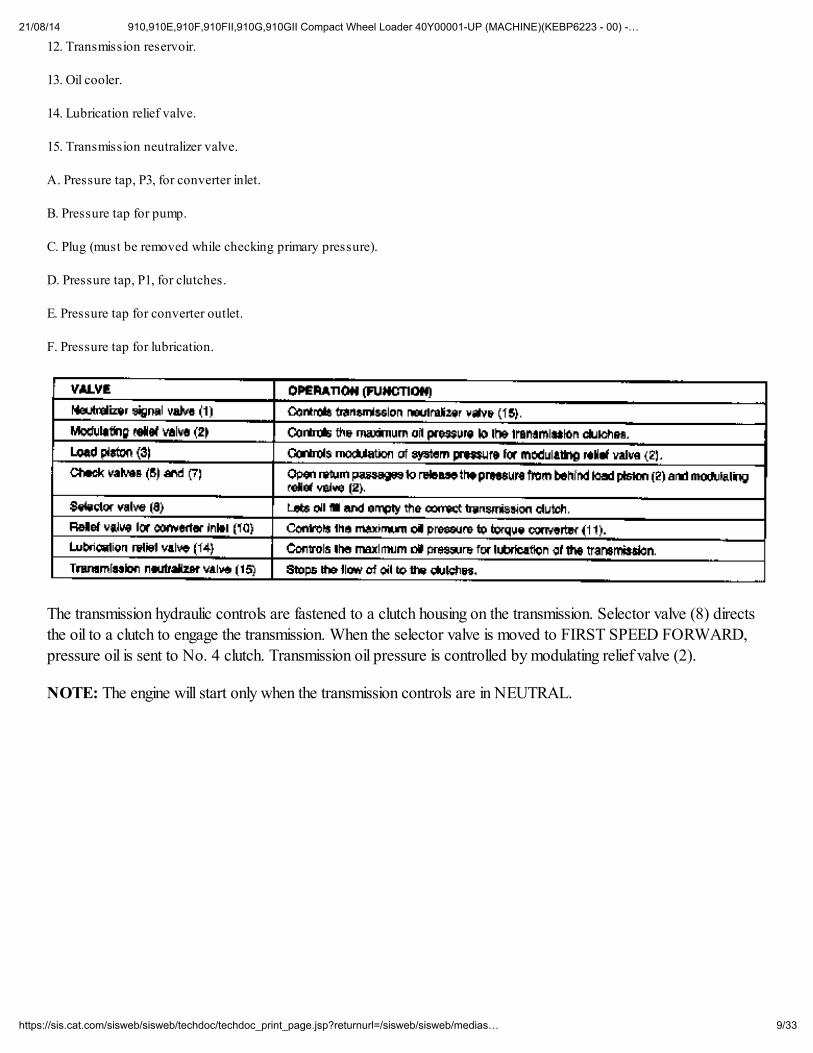
12. Transmission reservoir.
13. Oil cooler.
14. Lubrication relief valve.
15. Transmission neutralizer valve.
A. Pressure tap, P3, for converter inlet.
B. Pressure tap for pump.
C. Plug (must be removed while checking primary pressure).
D. Pressure tap, P1, for clutches.
E. Pressure tap for converter outlet.
F. Pressure tap for lubrication.
The transmission hydraulic controls are fastened to a clutch housing on the transmission. Selector valve (8) directsthe oil to a clutch to engage the transmission. When the selector valve is moved to FIRST SPEED FORWARD,
pressure oil is sent to No. 4 clutch. Transmission oil pressure is controlled by modulating relief valve (2).
NOTE: The engine will start only when the transmission controls are in NEUTRAL.
21/08/14 910,910E,910F,910FII,910G,910GII Compact Wheel Loader 40Y00001-UP (MACHINE)(KEBP6223 - 00) -…
10/33https://sis.cat.com/sisweb/sisweb/techdoc/techdoc_print_page.jsp?returnurl=/sisweb/sisweb/medias…
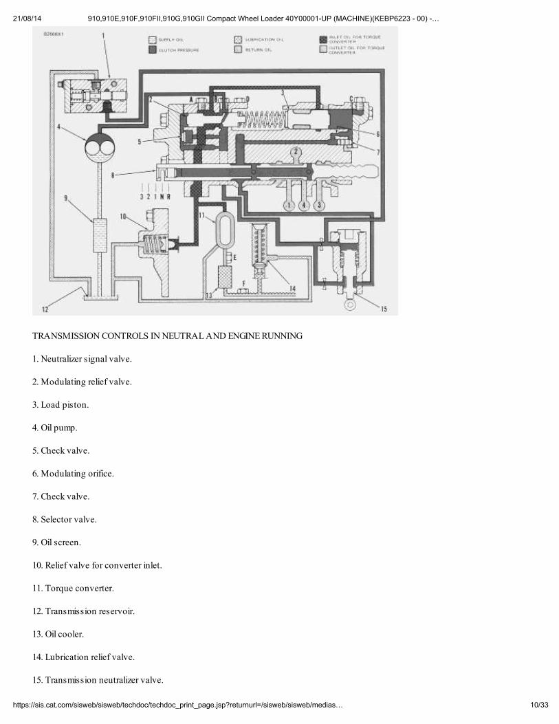
TRANSMISSION CONTROLS IN NEUTRAL AND ENGINE RUNNING
1. Neutralizer signal valve.
2. Modulating relief valve.
3. Load piston.
4. Oil pump.
5. Check valve.
6. Modulating orifice.
7. Check valve.
8. Selector valve.
9. Oil screen.
10. Relief valve for converter inlet.
11. Torque converter.
12. Transmission reservoir.
13. Oil cooler.
14. Lubrication relief valve.
15. Transmission neutralizer valve.
21/08/14 910,910E,910F,910FII,910G,910GII Compact Wheel Loader 40Y00001-UP (MACHINE)(KEBP6223 - 00) -…
11/33https://sis.cat.com/sisweb/sisweb/techdoc/techdoc_print_page.jsp?returnurl=/sisweb/sisweb/medias…
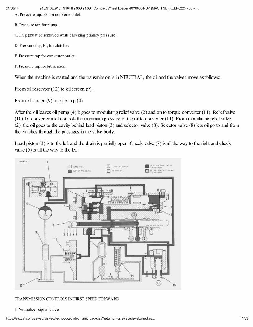
A. Pressure tap, P3, for converter inlet.
B. Pressure tap for pump.
C. Plug (must be removed while checking primary pressure).
D. Pressure tap, P1, for clutches.
E. Pressure tap for converter outlet.
F. Pressure tap for lubrication.
When the machine is started and the transmission is in NEUTRAL, the oil and the valves move as follows:
From oil reservoir (12) to oil screen (9).
From oil screen (9) to oil pump (4).
After the oil leaves oil pump (4) it goes to modulating relief valve (2) and on to torque converter (11). Relief valve(10) for converter inlet controls the maximum pressure of the oil to converter (11). From modulating relief valve
(2), the oil goes to the cavity behind load piston (3) and selector valve (8). Selector valve (8) lets oil go to and from
the clutches through the passages in the valve body.
Load piston (3) is to the left and the drain is partially open. Check valve (7) is all the way to the right and checkvalve (5) is all the way to the left.
TRANSMISSION CONTROLS IN FIRST SPEED FORWARD
1. Neutralizer signal valve.
21/08/14 910,910E,910F,910FII,910G,910GII Compact Wheel Loader 40Y00001-UP (MACHINE)(KEBP6223 - 00) -…
12/33https://sis.cat.com/sisweb/sisweb/techdoc/techdoc_print_page.jsp?returnurl=/sisweb/sisweb/medias…
2. Modulating relief valve.
3. Load piston.
4. Oil pump.
5. Check valve.
6. Modulating orifice.
7. Check valve.
8. Selector valve.
9. Oil screen.
10. Relief valve for converter inlet.
11. Torque converter.
12. Transmission reservoir.
13. Oil cooler.
14. Lubrication relief valve.
15. Transmission neutralizer valve.
A. Pressure tap, P3, for converter inlet.
B. Pressure tap for pump.
C. Plug (must be removed while checking primary pressure).
D. Pressure tap, P1, for clutches.
E. Pressure tap for converter outlet.
F. Pressure tap for lubrication.
When a shift is made into FIRST SPEED FORWARD, the pressure in the system goes down and the force of thesprings move modulating relief valve (2) all the way to the left and load piston (3) is moved to the right. Whenmodulating relief valve (2) moves to the left, flow to the torque converter is less. As No. 4 clutch and accumulator
(15) fill, the pressure in the system will increase. When the pressure of the oil becomes higher than the force of thesprings, the oil again goes to the torque converter. Check valve (7) is in a position to close the passage, behind loadpiston (3), that lets oil go back to oil reservoir (12). As the system pressure increases, load piston (3) moves to theleft and the force of the springs against modulating relief valve (2) is higher. The pressure increases gradually. This
gradual increase in pressure is known as modulation.
When selector valve (8) is moved from FIRST SPEED FORWARD, the oil pressure in the No. 4 clutch, will drain
back to transmission reservoir (12).
21/08/14 910,910E,910F,910FII,910G,910GII Compact Wheel Loader 40Y00001-UP (MACHINE)(KEBP6223 - 00) -…
13/33https://sis.cat.com/sisweb/sisweb/techdoc/techdoc_print_page.jsp?returnurl=/sisweb/sisweb/medias…
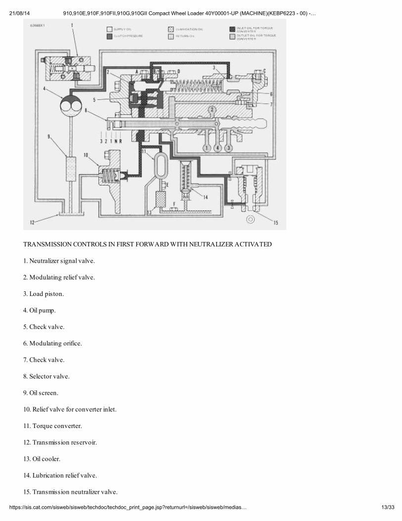
TRANSMISSION CONTROLS IN FIRST FORWARD WITH NEUTRALIZER ACTIVATED
1. Neutralizer signal valve.
2. Modulating relief valve.
3. Load piston.
4. Oil pump.
5. Check valve.
6. Modulating orifice.
7. Check valve.
8. Selector valve.
9. Oil screen.
10. Relief valve for converter inlet.
11. Torque converter.
12. Transmission reservoir.
13. Oil cooler.
14. Lubrication relief valve.
15. Transmission neutralizer valve.
21/08/14 910,910E,910F,910FII,910G,910GII Compact Wheel Loader 40Y00001-UP (MACHINE)(KEBP6223 - 00) -…
14/33https://sis.cat.com/sisweb/sisweb/techdoc/techdoc_print_page.jsp?returnurl=/sisweb/sisweb/medias…
A. Pressure tap, P3, for converter inlet.
B. Pressure tap for pump.
C. Plug (must be removed while checking primary pressure).
D. Pressure tap, P1, for clutches.
E. Pressure tap for converter outlet.
F. Pressure tap for lubrication.
Neutralizer signal valve (1) is activated when the left foot pedal for the brakes is pushed down. The movement of
the pedal linkage will allow the spring to push the stem in neutralizer signal valve (1) to the right. The movement ofthe stem will open a passage in the valve and allow the clutch pressure oil to go back to transmission reservoir (12).Transmission neutralizer valve (15) will now move up and stop the flow of clutch pressure oil to selector valve (8).
With the flow of clutch pressure oil stopped, the clutch in the transmission that was engaged is now disengaged.With the clutch disengaged the machine will not move. Load piston (3) will move to the right and cause check valve(7 to move to the left. When check valve (7) moves to the left the drain passage will be open.
When the left pedal is released, the stem in the neutralizer signal valve will be pushed back to the left. Themovement of the stem will stop the clutch pressure oil from going back to the reservoir. The pressure will increase
above transmission neutralizer valve (15) and force it down against the force of the spring. The movement of thetransmission neutralizer valve will open the passage and allow clutch pressure oil to go to selector valve (8) andmove check valve (7) to the right and let pressure oil move load piston (3) to the left. The clutch oil pressure willincrease and engage the proper clutch in the transmission.
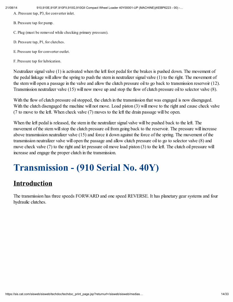
Transmission - (910 Serial No. 40Y)
Introduction
The transmission has three speeds FORWARD and one speed REVERSE. It has planetary gear systems and fourhydraulic clutches.
21/08/14 910,910E,910F,910FII,910G,910GII Compact Wheel Loader 40Y00001-UP (MACHINE)(KEBP6223 - 00) -…
15/33https://sis.cat.com/sisweb/sisweb/techdoc/techdoc_print_page.jsp?returnurl=/sisweb/sisweb/medias…
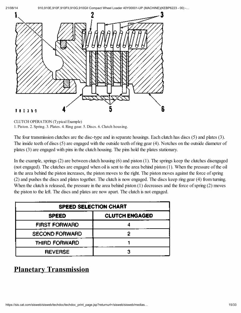
CLUTCH OPERATION (Typical Example) 1. Piston. 2. Spring. 3. Plates. 4. Ring gear. 5. Discs. 6. Clutch housing.
The four transmission clutches are the disc-type and in separate housings. Each clutch has discs (5) and plates (3).The inside teeth of discs (5) are engaged with the outside teeth of ring gear (4). Notches on the outside diameter ofplates (3) are engaged with pins in the clutch housing. The pins hold the plates stationary.
In the example, springs (2) are between clutch housing (6) and piston (1). The springs keep the clutches disengaged(not engaged). The clutches are engaged when oil is sent to the area behind piston (1). When the pressure of the oilin the area behind the piston increases, the piston moves to the right. The piston moves against the force of spring
(2) and pushes the discs and plates together. The clutch is now engaged. The discs keep ring gear (4) from turning.When the clutch is released, the pressure in the area behind piston (1) decreases and the force of spring (2) movesthe piston to the left. The discs and plates are now apart. The clutch is not engaged.
Planetary Transmission
21/08/14 910,910E,910F,910FII,910G,910GII Compact Wheel Loader 40Y00001-UP (MACHINE)(KEBP6223 - 00) -…
16/33https://sis.cat.com/sisweb/sisweb/techdoc/techdoc_print_page.jsp?returnurl=/sisweb/sisweb/medias…
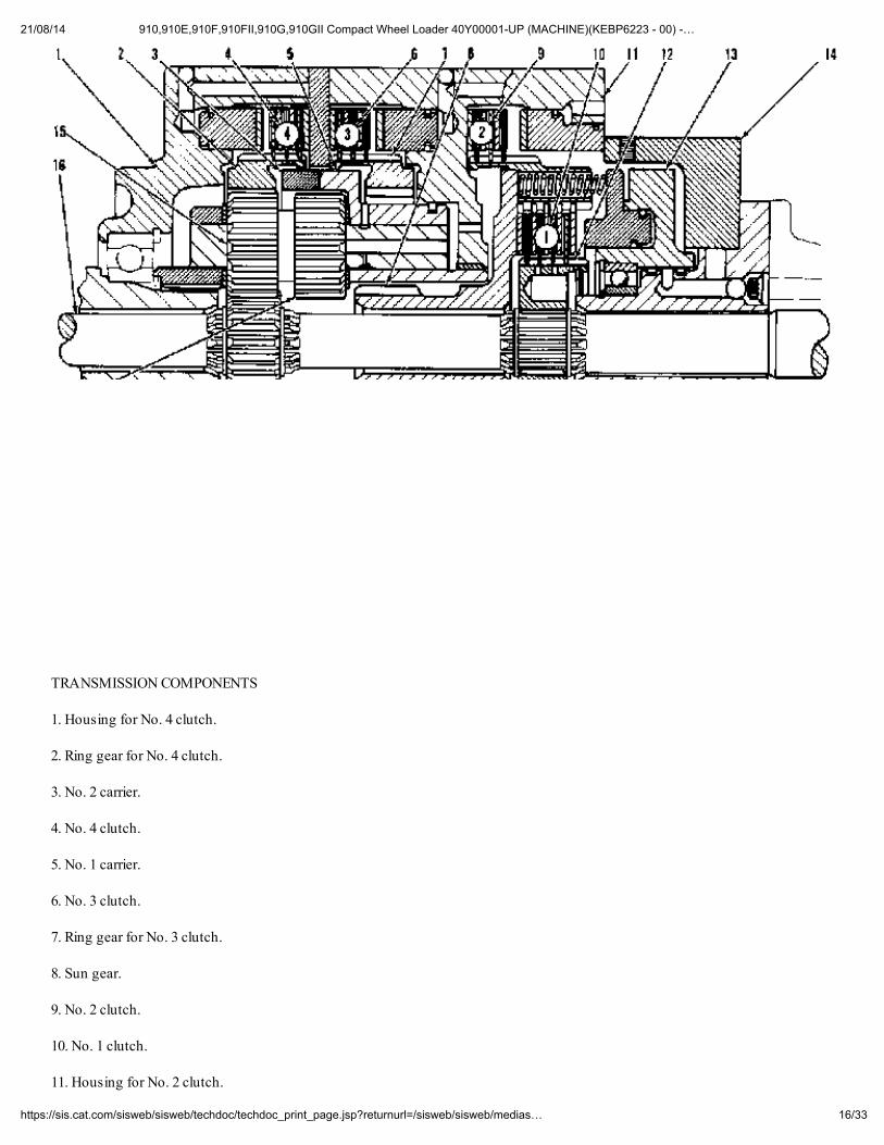
TRANSMISSION COMPONENTS
1. Housing for No. 4 clutch.
2. Ring gear for No. 4 clutch.
3. No. 2 carrier.
4. No. 4 clutch.
5. No. 1 carrier.
6. No. 3 clutch.
7. Ring gear for No. 3 clutch.
8. Sun gear.
9. No. 2 clutch.
10. No. 1 clutch.
11. Housing for No. 2 clutch.
21/08/14 910,910E,910F,910FII,910G,910GII Compact Wheel Loader 40Y00001-UP (MACHINE)(KEBP6223 - 00) -…
17/33https://sis.cat.com/sisweb/sisweb/techdoc/techdoc_print_page.jsp?returnurl=/sisweb/sisweb/medias…
12. Hub.
13. Rotating housing.
14. Manifold.
15. Planet gear.
16. Transmission shaft.
17. Planet gear.
18. Output gear.
19. Sun gear.
20. Planet gear.
21. Planet gear.
22. Ring gear for No. 2 clutch.
The planetary transmission has four clutches, No. 1, No. 2, No. 3 and No. 4 and the carriers for the planet gears.The No. 1 clutch is for THIRD SPEED FORWARD. The No. 2 clutch is for SECOND SPEED FORWARD.The No. 3 is for the REVERSE SPEED. The No. 4 clutch is for FIRST SPEED FORWARD.
All components inside the planetary transmission turn when the controls are in FIRST, SECOND, THIRD orREVERSE SPEED.
The following components are always used in all speeds including REVERSE.
Sun (input) gear (19).Output gear (18).Planet carriers (3) and (5).Transmission shaft (16).
NOTE: In the drawings that follow, only the parts that move and send power are a darker color.
First Speed Forward
21/08/14 910,910E,910F,910FII,910G,910GII Compact Wheel Loader 40Y00001-UP (MACHINE)(KEBP6223 - 00) -…
18/33https://sis.cat.com/sisweb/sisweb/techdoc/techdoc_print_page.jsp?returnurl=/sisweb/sisweb/medias…
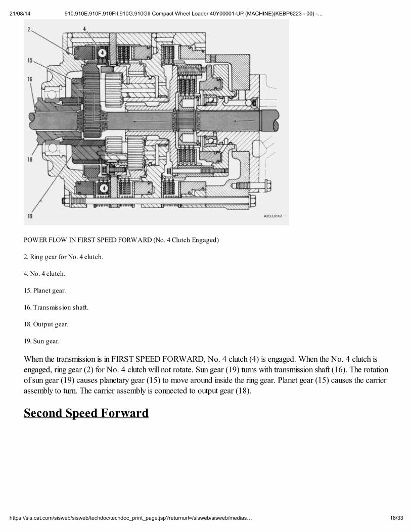
POWER FLOW IN FIRST SPEED FORWARD (No. 4 Clutch Engaged)
2. Ring gear for No. 4 clutch.
4. No. 4 clutch.
15. Planet gear.
16. Transmission shaft.
18. Output gear.
19. Sun gear.
When the transmission is in FIRST SPEED FORWARD, No. 4 clutch (4) is engaged. When the No. 4 clutch isengaged, ring gear (2) for No. 4 clutch will not rotate. Sun gear (19) turns with transmission shaft (16). The rotation
of sun gear (19) causes planetary gear (15) to move around inside the ring gear. Planet gear (15) causes the carrierassembly to turn. The carrier assembly is connected to output gear (18).
Second Speed Forward
21/08/14 910,910E,910F,910FII,910G,910GII Compact Wheel Loader 40Y00001-UP (MACHINE)(KEBP6223 - 00) -…
19/33https://sis.cat.com/sisweb/sisweb/techdoc/techdoc_print_page.jsp?returnurl=/sisweb/sisweb/medias…
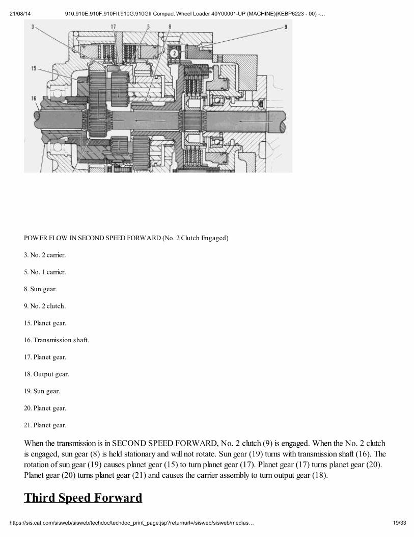
POWER FLOW IN SECOND SPEED FORWARD (No. 2 Clutch Engaged)
3. No. 2 carrier.
5. No. 1 carrier.
8. Sun gear.
9. No. 2 clutch.
15. Planet gear.
16. Transmission shaft.
17. Planet gear.
18. Output gear.
19. Sun gear.
20. Planet gear.
21. Planet gear.
When the transmission is in SECOND SPEED FORWARD, No. 2 clutch (9) is engaged. When the No. 2 clutch
is engaged, sun gear (8) is held stationary and will not rotate. Sun gear (19) turns with transmission shaft (16). Therotation of sun gear (19) causes planet gear (15) to turn planet gear (17). Planet gear (17) turns planet gear (20).Planet gear (20) turns planet gear (21) and causes the carrier assembly to turn output gear (18).
Third Speed Forward
21/08/14 910,910E,910F,910FII,910G,910GII Compact Wheel Loader 40Y00001-UP (MACHINE)(KEBP6223 - 00) -…
20/33https://sis.cat.com/sisweb/sisweb/techdoc/techdoc_print_page.jsp?returnurl=/sisweb/sisweb/medias…
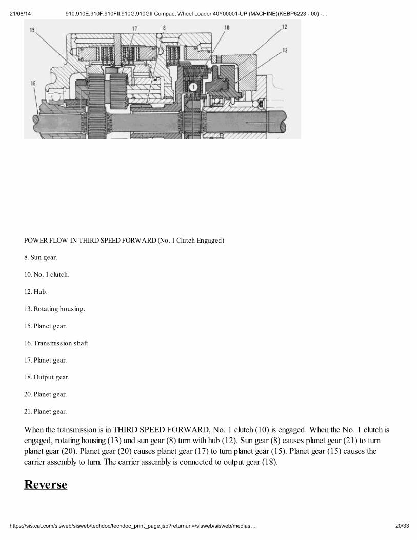
POWER FLOW IN THIRD SPEED FORWARD (No. 1 Clutch Engaged)
8. Sun gear.
10. No. 1 clutch.
12. Hub.
13. Rotating housing.
15. Planet gear.
16. Transmission shaft.
17. Planet gear.
18. Output gear.
20. Planet gear.
21. Planet gear.
When the transmission is in THIRD SPEED FORWARD, No. 1 clutch (10) is engaged. When the No. 1 clutch isengaged, rotating housing (13) and sun gear (8) turn with hub (12). Sun gear (8) causes planet gear (21) to turnplanet gear (20). Planet gear (20) causes planet gear (17) to turn planet gear (15). Planet gear (15) causes thecarrier assembly to turn. The carrier assembly is connected to output gear (18).
Reverse
21/08/14 910,910E,910F,910FII,910G,910GII Compact Wheel Loader 40Y00001-UP (MACHINE)(KEBP6223 - 00) -…
21/33https://sis.cat.com/sisweb/sisweb/techdoc/techdoc_print_page.jsp?returnurl=/sisweb/sisweb/medias…
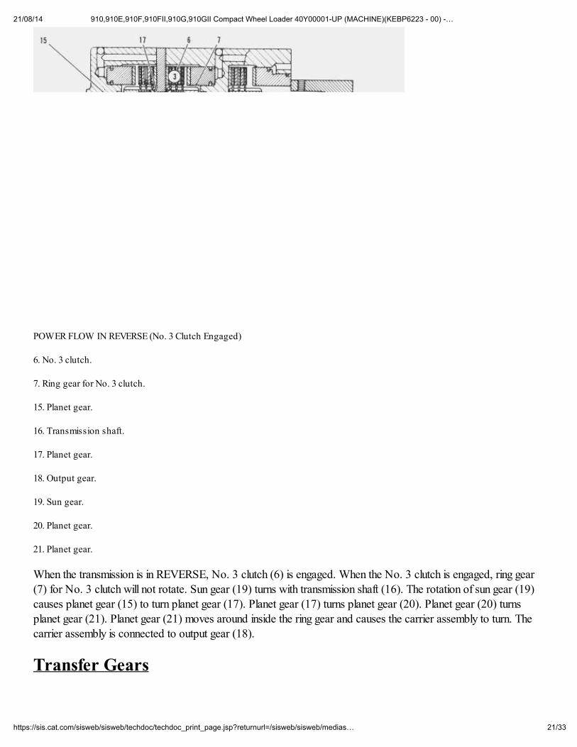
POWER FLOW IN REVERSE (No. 3 Clutch Engaged)
6. No. 3 clutch.
7. Ring gear for No. 3 clutch.
15. Planet gear.
16. Transmission shaft.
17. Planet gear.
18. Output gear.
19. Sun gear.
20. Planet gear.
21. Planet gear.
When the transmission is in REVERSE, No. 3 clutch (6) is engaged. When the No. 3 clutch is engaged, ring gear(7) for No. 3 clutch will not rotate. Sun gear (19) turns with transmission shaft (16). The rotation of sun gear (19)causes planet gear (15) to turn planet gear (17). Planet gear (17) turns planet gear (20). Planet gear (20) turns
planet gear (21). Planet gear (21) moves around inside the ring gear and causes the carrier assembly to turn. Thecarrier assembly is connected to output gear (18).
Transfer Gears
21/08/14 910,910E,910F,910FII,910G,910GII Compact Wheel Loader 40Y00001-UP (MACHINE)(KEBP6223 - 00) -…
22/33https://sis.cat.com/sisweb/sisweb/techdoc/techdoc_print_page.jsp?returnurl=/sisweb/sisweb/medias…
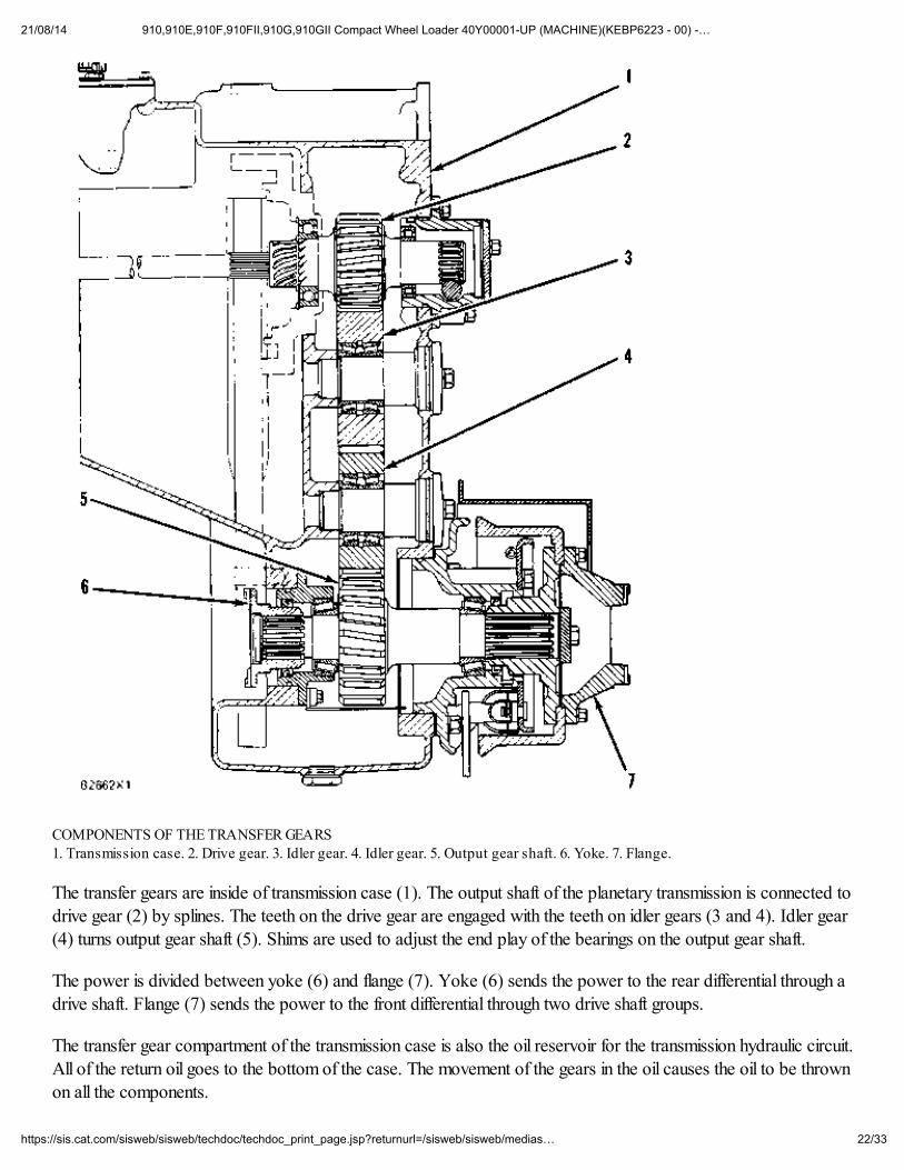
COMPONENTS OF THE TRANSFER GEARS 1. Transmission case. 2. Drive gear. 3. Idler gear. 4. Idler gear. 5. Output gear shaft. 6. Yoke. 7. Flange.
The transfer gears are inside of transmission case (1). The output shaft of the planetary transmission is connected to
drive gear (2) by splines. The teeth on the drive gear are engaged with the teeth on idler gears (3 and 4). Idler gear(4) turns output gear shaft (5). Shims are used to adjust the end play of the bearings on the output gear shaft.
The power is divided between yoke (6) and flange (7). Yoke (6) sends the power to the rear differential through adrive shaft. Flange (7) sends the power to the front differential through two drive shaft groups.
The transfer gear compartment of the transmission case is also the oil reservoir for the transmission hydraulic circuit.All of the return oil goes to the bottom of the case. The movement of the gears in the oil causes the oil to be thrownon all the components.
21/08/14 910,910E,910F,910FII,910G,910GII Compact Wheel Loader 40Y00001-UP (MACHINE)(KEBP6223 - 00) -…
23/33https://sis.cat.com/sisweb/sisweb/techdoc/techdoc_print_page.jsp?returnurl=/sisweb/sisweb/medias…
General Information - (910 Serial No. 41Y)
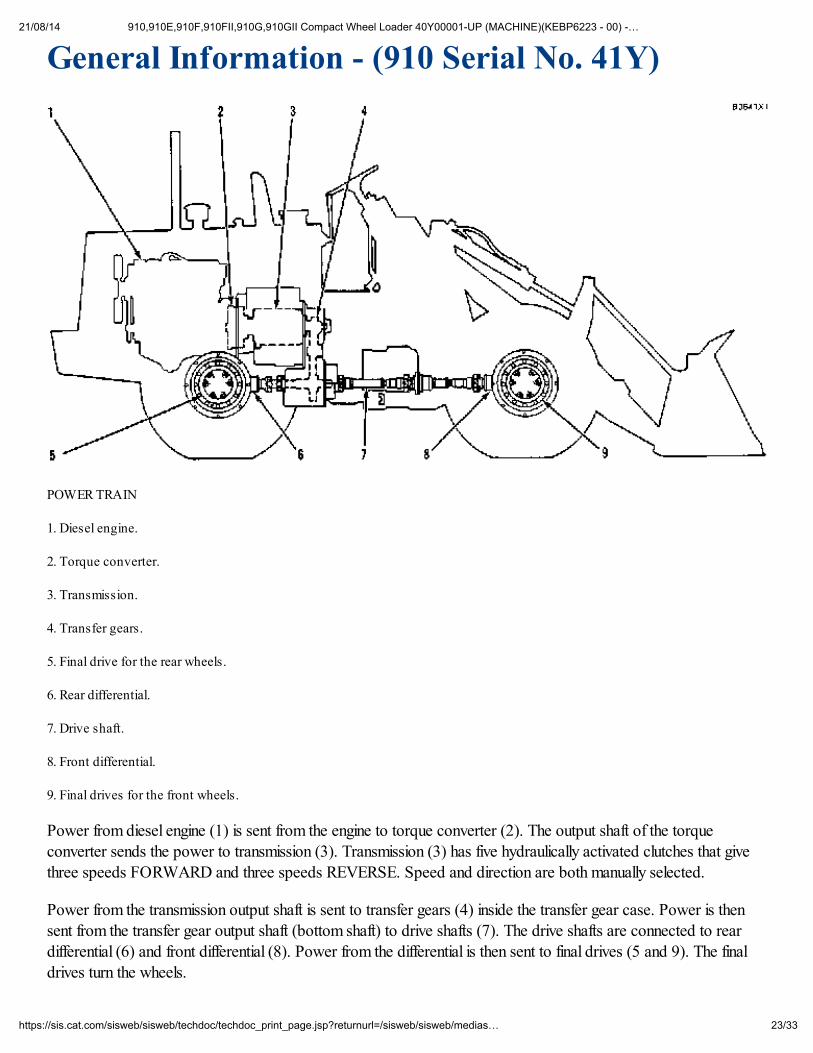
POWER TRAIN
1. Diesel engine.
2. Torque converter.
3. Transmission.
4. Transfer gears.
5. Final drive for the rear wheels.
6. Rear differential.
7. Drive shaft.
8. Front differential.
9. Final drives for the front wheels.
Power from diesel engine (1) is sent from the engine to torque converter (2). The output shaft of the torqueconverter sends the power to transmission (3). Transmission (3) has five hydraulically activated clutches that give
three speeds FORWARD and three speeds REVERSE. Speed and direction are both manually selected.
Power from the transmission output shaft is sent to transfer gears (4) inside the transfer gear case. Power is then
sent from the transfer gear output shaft (bottom shaft) to drive shafts (7). The drive shafts are connected to reardifferential (6) and front differential (8). Power from the differential is then sent to final drives (5 and 9). The finaldrives turn the wheels.
21/08/14 910,910E,910F,910FII,910G,910GII Compact Wheel Loader 40Y00001-UP (MACHINE)(KEBP6223 - 00) -…
24/33https://sis.cat.com/sisweb/sisweb/techdoc/techdoc_print_page.jsp?returnurl=/sisweb/sisweb/medias…
Torque Converter - (910 Serial No. 41Y)
The torque converter connects the engine to the planetary transmission. This connection between the engine and thetransmission is a hydraulic connection. There is no direct mechanical connection between the engine and thetransmission.
The torque converter uses oil to send torque from the engine to the transmission. When the machine is workingagainst a load, the torque converter can multiply the torque from the engine and send a higher torque to thetransmission.
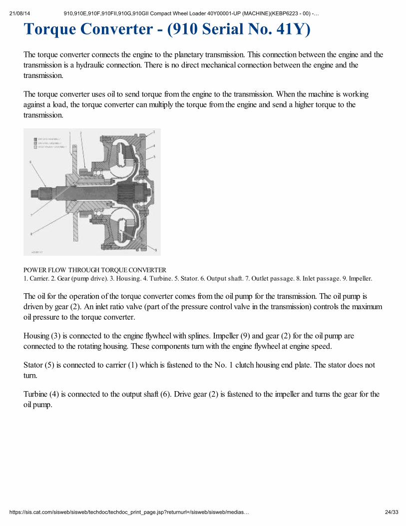
POWER FLOW THROUGH TORQUE CONVERTER 1. Carrier. 2. Gear (pump drive). 3. Housing. 4. Turbine. 5. Stator. 6. Output shaft. 7. Outlet passage. 8. Inlet passage. 9. Impeller.
The oil for the operation of the torque converter comes from the oil pump for the transmission. The oil pump isdriven by gear (2). An inlet ratio valve (part of the pressure control valve in the transmission) controls the maximum
oil pressure to the torque converter.
Housing (3) is connected to the engine flywheel with splines. Impeller (9) and gear (2) for the oil pump are
connected to the rotating housing. These components turn with the engine flywheel at engine speed.
Stator (5) is connected to carrier (1) which is fastened to the No. 1 clutch housing end plate. The stator does notturn.
Turbine (4) is connected to the output shaft (6). Drive gear (2) is fastened to the impeller and turns the gear for theoil pump.
21/08/14 910,910E,910F,910FII,910G,910GII Compact Wheel Loader 40Y00001-UP (MACHINE)(KEBP6223 - 00) -…
25/33https://sis.cat.com/sisweb/sisweb/techdoc/techdoc_print_page.jsp?returnurl=/sisweb/sisweb/medias…
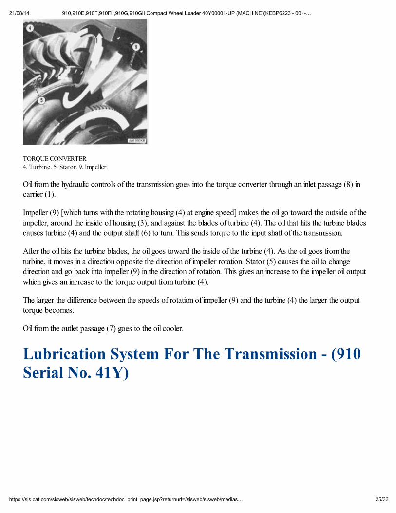
TORQUE CONVERTER 4. Turbine. 5. Stator. 9. Impeller.
Oil from the hydraulic controls of the transmission goes into the torque converter through an inlet passage (8) incarrier (1).
Impeller (9) [which turns with the rotating housing (4) at engine speed] makes the oil go toward the outside of theimpeller, around the inside of housing (3), and against the blades of turbine (4). The oil that hits the turbine bladescauses turbine (4) and the output shaft (6) to turn. This sends torque to the input shaft of the transmission.
After the oil hits the turbine blades, the oil goes toward the inside of the turbine (4). As the oil goes from theturbine, it moves in a direction opposite the direction of impeller rotation. Stator (5) causes the oil to changedirection and go back into impeller (9) in the direction of rotation. This gives an increase to the impeller oil output
which gives an increase to the torque output from turbine (4).
The larger the difference between the speeds of rotation of impeller (9) and the turbine (4) the larger the output
torque becomes.
Oil from the outlet passage (7) goes to the oil cooler.
Lubrication System For The Transmission - (910Serial No. 41Y)
21/08/14 910,910E,910F,910FII,910G,910GII Compact Wheel Loader 40Y00001-UP (MACHINE)(KEBP6223 - 00) -…
26/33https://sis.cat.com/sisweb/sisweb/techdoc/techdoc_print_page.jsp?returnurl=/sisweb/sisweb/medias…
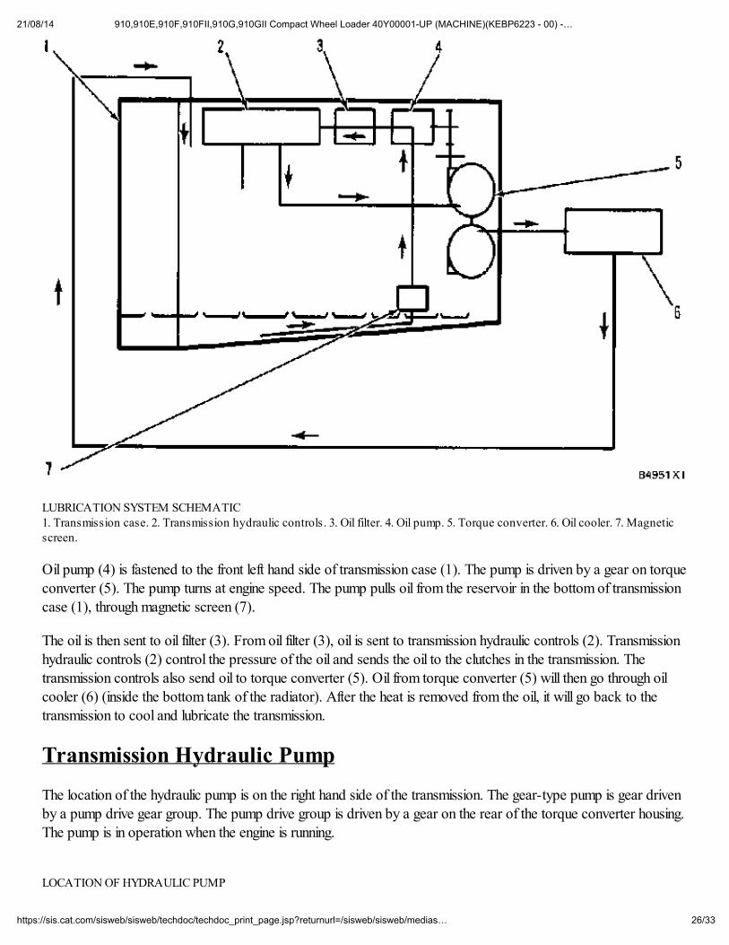
LUBRICATION SYSTEM SCHEMATIC 1. Transmission case. 2. Transmission hydraulic controls. 3. Oil filter. 4. Oil pump. 5. Torque converter. 6. Oil cooler. 7. Magneticscreen.
Oil pump (4) is fastened to the front left hand side of transmission case (1). The pump is driven by a gear on torqueconverter (5). The pump turns at engine speed. The pump pulls oil from the reservoir in the bottom of transmissioncase (1), through magnetic screen (7).
The oil is then sent to oil filter (3). From oil filter (3), oil is sent to transmission hydraulic controls (2). Transmissionhydraulic controls (2) control the pressure of the oil and sends the oil to the clutches in the transmission. The
transmission controls also send oil to torque converter (5). Oil from torque converter (5) will then go through oilcooler (6) (inside the bottom tank of the radiator). After the heat is removed from the oil, it will go back to thetransmission to cool and lubricate the transmission.
Transmission Hydraulic Pump
The location of the hydraulic pump is on the right hand side of the transmission. The gear-type pump is gear drivenby a pump drive gear group. The pump drive group is driven by a gear on the rear of the torque converter housing.The pump is in operation when the engine is running.
LOCATION OF HYDRAULIC PUMP
21/08/14 910,910E,910F,910FII,910G,910GII Compact Wheel Loader 40Y00001-UP (MACHINE)(KEBP6223 - 00) -…
27/33https://sis.cat.com/sisweb/sisweb/techdoc/techdoc_print_page.jsp?returnurl=/sisweb/sisweb/medias…
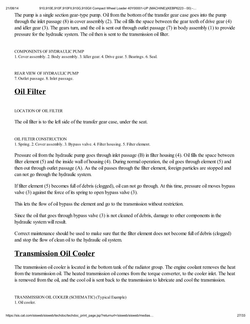
The pump is a single section gear-type pump. Oil from the bottom of the transfer gear case goes into the pumpthrough the inlet passage (8) in cover assembly (2). The oil fills the space between the gear teeth of drive gear (4)and idler gear (3). The gears turn, and the oil is sent out through outlet passage (7) in body assembly (1) to providepressure for the hydraulic system. The oil then is sent to the transmission oil filter.
COMPONENTS OF HYDRAULIC PUMP 1. Cover assembly. 2. Body assembly. 3. Idler gear. 4. Drive gear. 5. Bearings. 6. Seal.
REAR VIEW OF HYDRAULIC PUMP 7. Outlet passage. 8. Inlet passage.
Oil Filter
LOCATION OF OIL FILTER
The oil filter is to the left side of the transfer gear case, under the seat.
OIL FILTER CONSTRUCTION 1. Spring. 2. Cover assembly. 3. Bypass valve. 4. Filter housing. 5. Filter element.
Pressure oil from the hydraulic pump goes through inlet passage (B) in filter housing (4). Oil fills the space betweenfilter element (5) and the inside wall of housing (4). During normal operation, the oil goes through element (5) andthen out through outlet passage (A). As the oil passes through the filter element, foreign particles are stopped andcan not go through the hydraulic system.
If filter element (5) becomes full of debris (clogged), oil can not go through. At this time, pressure oil moves bypassvalve (3) against the force of its spring to open bypass valve (3).
This lets the flow of oil bypass the element and go to the transmission without restriction.
Since the oil that goes through bypass valve (3) is not cleaned of debris, damage to other components in thehydraulic system will result.
Correct maintenance should be used to make sure that the filter element does not become full of debris (clogged)and stop the flow of clean oil to the hydraulic oil system.
Transmission Oil Cooler
The transmission oil cooler is located in the bottom tank of the radiator group. The engine coolant removes the heat
from the transmission oil. The heated transmission oil comes from the torque converter, to the cooler inlet. The heatis removed from the oil, and the cool oil is sent back to the transmission to lubricate and cool the transmission.
TRANSMISSION OIL COOLER (SCHEMATIC) (Typical Example) 1. Oil cooler.
21/08/14 910,910E,910F,910FII,910G,910GII Compact Wheel Loader 40Y00001-UP (MACHINE)(KEBP6223 - 00) -…
28/33https://sis.cat.com/sisweb/sisweb/techdoc/techdoc_print_page.jsp?returnurl=/sisweb/sisweb/medias…
Transmission Hydraulic Controls - (910 Serial No.41Y)
Introduction
The transmission hydraulic controls are installed on the planetary transmission. The controls have a top plate (1),selector and pressure control valve group (2), plate (3) and neutralizer valve group (4).
TRANSMISSION HYDRAULIC CONTROLS (Side View) 1. Plate. 2. Selector and pressure control valve group. 3. Plate. 4. Neutralizer valve group.
TRANSMISSION HYDRAULIC CONTROLS (Top View) 1. Plate. 5. Oil tube (inlet from pump). 6. Outlet to neutralizer signal valve. 7. Speed selector spool. 8. Direction selection spool.
Inlet oil for operation of the hydraulic controls comes from the filter and goes through tube (5) to the pressurecontrol valve.
Oil pressure goes through outlet (6) to the neutralizer signal valve.
Neutralizer Valve
TRANSMISSION NEUTRALIZER VALVE 1. Manifold. 2. Inlet from pressure control valve. 3. Speed clutch oil inlet. 4. Spring. 5. Drain. 6. Spool. 7. Passage to neutralizersignal valve.
The neutralizer valve is in the bottom manifold of the hydraulic controls.
The neutralizer valve is activated by the left brake pedal. The left brake pedal moves the spool inside of thetransmission neutralizer signal valve. When the brake pedal is pushed, oil pressure that was used to hold spool (6)
to the left is allowed to go to drain through the transmission neutralizer signal valve. Spring (4) will move spool (6)to the right and open the chamber at the left of the pressure differential valve to the reservoir through drain (5).
The oil pressure in the directional clutch circuit decreases, and the directional clutch is no longer engaged.
Since a speed and direction clutch must both be engaged before power goes through the transmission, power does
not go through the transmission when the left brake pedal is pushed.
LOCATION OF NEUTRALIZER SIGNAL VALVE
When the left brake pedal is released, the passage to the reservoir is closed. Oil pressure in the directional clutchwill then increase until the directional clutch is engaged. Power goes through the transmission.
Neutralizer Signal Valve
21/08/14 910,910E,910F,910FII,910G,910GII Compact Wheel Loader 40Y00001-UP (MACHINE)(KEBP6223 - 00) -…
29/33https://sis.cat.com/sisweb/sisweb/techdoc/techdoc_print_page.jsp?returnurl=/sisweb/sisweb/medias…
The transmission neutralizer signal valve is controlled by the left brake pedal. When the left brake pedal is pushed,spool (1) is moved by spring (3) to the position shown. Pressure oil in passage (2) will go to the reservoir throughdrain passage (4).
When the left pedal is released, the linkage will push spool (1) to the right and stop the flow of oil. The pressure willincrease in the pressure control valve for the directional clutch.
COMPONENTS OF TRANSMISSION NEUTRALIZER SIGNAL VALVE 1. Spool. 2. Passage from neutralizer valve. 3. Spring. 4. Drain passage.
Selector And Pressure Control Valve
SELECTOR AND PRESSURE CONTROL VALVE 1. Speed selector spool. 2. Modulation relief valve. 3. Load piston. 4. Inlet passage from transmission oil pump. 5. Outlet passageto torque converter. 6. Ratio valve. 7. Pressure differential valve. 8. Direction selector spool.
The selector and pressure control valve is connected to the planetary transmission. The valve is completely
enclosed by the transmission case.
Speed selector spool (1) and direction selector spool (8) are connected by linkage to the transmission selector
lever.
Engine Running (Transmission in Neutral)
TRANSMISSION HYDRAULIC CONTROLS (Engine Running, Transmission in Neutral)
1. Oil filter.
2. Torque converter.
3. Oil cooler.
4. Transmission neutralizer signal valve.
5. Speed selector spool.
6. Body of selector and pressure control valve.
7. Modulation relief valve.
8. Load piston.
9. Orifice.
10. Orifice.
11. Oil pump.
12. Ratio valve for torque converter.
21/08/14 910,910E,910F,910FII,910G,910GII Compact Wheel Loader 40Y00001-UP (MACHINE)(KEBP6223 - 00) -…
30/33https://sis.cat.com/sisweb/sisweb/techdoc/techdoc_print_page.jsp?returnurl=/sisweb/sisweb/medias…
13. Pressure differential valve.
14. Neutralizer valve.
15. Direction selector spool.
16. Magnetic screen.
17. Reservoir in bottom of transfer gear case.
18. Neutralizer valve body.
A. Pressure tap for pump.
B. Pressure tap for converter outlet.
C. Pressure tap for transmission lubrication.
D. Pressure tap for converter inlet (P3).
E. Pressure tap for speed clutch (P1).
F. Pressure tap for direction clutch (P2).
When the engine is started, oil pump (11) pulls oil from reservoir (17). This sends the oil through oil filter (1) to theselector and pressure control valve, which is part of the transmission hydraulic controls.
When the transmission selector lever is in NEUTRAL, direction selector spool (15) is in the position shown in theschematic. Speed selector spool (5) can be in either FIRST, SECOND or THIRD speed position.
The position of direction selector spool (15) opens No. 3 clutch to pump oil. Speed clutches No. 4 and No. 5 areopen to the reservoir. The position of direction selector spool (15) opens the right end of pressure differential valve(13) to the reservoir.
Oil from the pump goes to modulation relief valve (7). It fills the chamber around the modulation relief valve. The oilgoes through an orifice in the valve spool and opens the poppet valve. The oil fills the slug chamber at the left end ofthe valve spool.
Pump oil also goes through the flow control orifice to direction selector spool (15). The oil can then flow to ratiovalve (12) and pressure differential valve (13).
The oil to ratio valve (12) for the torque converter goes through an orifice in the valve spool and fills the slugchamber.
The oil to the pressure differential valve goes through orifice (10) in the valve spool. Oil starts to fill the chamber atthe left end of the valve spool. When the transmission selector lever is in NEUTRAL, orifice (9) can not send oil tothe reservoir because the passage around the orifices is filled with pump oil. This lets the differential valve move a
small amount to the right (to the SET position). In this position, orifice (9) is closed by the valve body. The pressuredifferential valve can move no farther to the right because of the drain passage at the left end of the valve. In thisposition, no oil is sent to the directional clutches.
Operation of Modulation Relief Valve
21/08/14 910,910E,910F,910FII,910G,910GII Compact Wheel Loader 40Y00001-UP (MACHINE)(KEBP6223 - 00) -…
31/33https://sis.cat.com/sisweb/sisweb/techdoc/techdoc_print_page.jsp?returnurl=/sisweb/sisweb/medias…
Pump oil, that flows to the pressure differential valve, also goes through an orifice to the right end of load piston (8).The right end of the load piston is closed to the reservoir by the position of pressure differential valve (13). The
flow of oil to load piston (8) is restricted by the orifice.
When No. 3 clutch is full of oil, the pressure in the speed clutch circuit starts to increase. The increase is felt in the
slug chamber at the left end of modulation relief valve (7). When the pressure in the speed clutch circuit is at theprimary setting of the modulation relief valve, the modulation relief valve moves to the right. This lets extra oil go tothe torque converter.
The pressure, felt by the modulation relief valve, is also felt on the right end of load piston (8). The orifice in thesupply passage to the load piston causes a short delay in the pressure increase at the right end of the load piston.This pressure increase at the end of the load piston moves the piston to the left. The movement to the left increasesthe force of the springs and moves modulation relief valve (7) to the left also. This causes a pressure increase in theslug chamber and moves the modulation relief valve back to the right.
This left and right movement of the modulation relief valve, along with the movement to the left of the load piston,causes the clutch pressure to increase gradually. This gradual increase in pressure is known as modulation.
The load piston movement to the left stops when the load piston moves to the drain passage. At this time,modulation stops. As oil goes out the drain passage, oil comes through the supply passage to the load pistonchamber. This keeps the load piston in position without any further movement. Pressure in the system will be limitedby the spring force on the modulation relief valve. At this time, the valve is opened to let oil flow to the torque
converter.
Operation of Ratio Valve
Ratio valve (12) for the torque converter controls the maximum pressure to the converter. Its primary purpose is toprevent damage to the converter components when the engine is started with cold oil.
The pressure to the torque converter, caused by restrictions to flow, is felt against the left end of the valve spool.This pressure pushes against the whole diameter of the valve spool.
Pressure from the speed clutch circuit is felt in the slug chamber of the valve spool. This pressure pushes againstonly the diameter of the slug.
The pressure (on the left end of valve) needed to move the valve to the right is less than the pressure (in slugchamber) needed to move the valve to the left.
When the inlet pressure to the torque converter gets to it maximum, the valve spool moves to the right. This lets theextra oil go to the reservoir. When the pressures are again in balance, spring force moves the valve back to the left.
All oil, not used by the clutches, goes to the ratio valve for the torque converter.
Engine Running (Neutral to First Speed Forward)
TRANSMISSION HYDRAULIC CONTROLS (Engine Running, Neutral to First Speed Forward)
1. Oil filter.
21/08/14 910,910E,910F,910FII,910G,910GII Compact Wheel Loader 40Y00001-UP (MACHINE)(KEBP6223 - 00) -…
32/33https://sis.cat.com/sisweb/sisweb/techdoc/techdoc_print_page.jsp?returnurl=/sisweb/sisweb/medias…
2. Torque converter.
3. Oil cooler.
4. Transmission neutralizer signal valve.
5. Speed selector spool.
6. Body of selector and pressure control valve.
7. Modulation relief valve.
8. Load piston.
9. Orifice.
10. Orifice.
11. Oil pump.
12. Ratio valve for torque converter.
13. Pressure differential valve.
14. Neutralizer valve.
15. Direction selector spool.
16. Magnetic screen.
17. Reservoir in bottom of transfer gear case.
18. Neutralizer valve body.
A. Pressure tap for pump.
B. Pressure tap for converter outlet.
C. Pressure tap for transmission lubrication.
D. Pressure tap for converter inlet (P3).
E. Pressure tap for speed clutch (P1).
F. Pressure tap for direction clutch (P2).
When the transmission selector lever is moved to FIRST SPEED FORWARD, speed selector spool (5) anddirection selector spool (15) move to the positions shown in the schematic.
The position of direction selector spool (15) opens a passage to No. 2 clutch. It also opens a passage from No. 1clutch to the reservoir.
The position of speed selector spool (5) opens a passage to No. 5 clutch to pump oil. It also opens No. 3 clutchand No. 4 clutch to the reservoir.
When the shift from NEUTRAL to FIRST SPEED FORWARD is made, No. 3 clutch is opened to the reservoir.
21/08/14 910,910E,910F,910FII,910G,910GII Compact Wheel Loader 40Y00001-UP (MACHINE)(KEBP6223 - 00) -…
33/33https://sis.cat.com/sisweb/sisweb/techdoc/techdoc_print_page.jsp?returnurl=/sisweb/sisweb/medias…
The pressure in the system decreases. Springs move modulation relief valve (7) toward the left. Pressure differentialvalve (13) moves until the oil from the right end of load piston (8) can go to the reservoir. This lets the load pistonmove to the right.
Speed clutch No. 5 starts to fill. When it is full of oil, the pressure increases in the system. This pressure increase isfelt through orifice (10) and against the left end of pressure differential valve. This moves the pressure differentialvalve until the right end of load piston (8) is closed to the reservoir. The differential valve also lets oil go to direction
clutch No. 2, and it starts to fill. The pressure differential valve will keep a 55 psi (380 kPa) pressure differencebetween the oil to the speed clutch and direction clutch. This lets the speed clutch engage before the directionclutch.
Also, as the pressure (P1) is increasing, neutralizer valve (14) in neutralizer valve body (18) is moved down. As theneutralizer valve moves down, the drian passage is closed. The pressure oil to the left of pressure differential valvecan not go to drain.
When the end of the load piston is closed to the reservoir, the pressure oil starts to fill the load piston chamberagain. The load piston starts to move to the left and modulation starts.
This movement of the load piston compresses the springs and moves the modulation relief valve to the left. Thiscauses the pressure of the pump oil in the slug chamber to go higher and moves the modulation relief valve back tothe right.
This modulation goes on until the clutches reach full