gl 3511331144
TRANSCRIPT
7/27/2019 Gl 3511331144
http://slidepdf.com/reader/full/gl-3511331144 1/12
Mohsen Broumand et al Int. Journal of Engineering Research and Application www.ijera.com ISSN : 2248-9622, Vol. 3, Issue 5, Sep-Oct 2013, pp.1133-1144
www.ijera.com 1133 | P a g e
Interphase Slipping Effect on Flame Propagation Characteristics
in Micro-Iron Dust Particles Mohsen Broumand, Saeed Shayamehr, Mehdi Bidabadi
Combustion Research Laboratory, School of Mechanical Engineering, Iran University of Science and
Technology
AbstractIn this paper, the impact of interphase slipping (i.e., relative velocity between micro-iron dust particles
suspended in air and surrounding gas flow) on flame propagation characteristics is studied. Initially, to obtain an
explicit algebraic equation for the flame velocity, mass and energy conservation equations are solved. Then,
dynamic equations of micro-iron particles during the upward flame propagation in a vertical duct are considered
to calculate the particle velocities as a function of their distances from the leading edge of the flame. After that,
by balancing the mass flux passing through a control volume above the leading edge of the flame, the change inthe number density of the particles is determined. As a result, it is shown that due to the interphase slipping
effect, mass concentration of micro-iron particles upon the leading edge of the flame is approximately twice as
large as it at a distance far from the flame. This accumulation causes flame moves in a denser dust cloud, which
has a significant effect on the flame propagation characteristics such as flame velocity and temperature. The
theoretical results show reasonable correlation with the experimental data.Keywords: Micro-iron particles; Interphase slipping; Flame velocity; Mass concentration; Heterogeneous
combustion
I. IntroductionStudy on the combustion of dust/gas
mixtures can be useful in many technological aspects
such as dust explosion hazards management, fire
suppression techniques, and fossil fuel combustion[1-4]. Aluminum powder is used in solid-fueled
propulsion systems in order to boost the combustion
enthalpy. It has been long that metal such as hafnium,
titanium, zirconium and beryllium are used as
energizing additives in propellants, incendiaries and
flame synthesis. There are also many reasons
supporting the importance of considering alternativeenergy carriers such as metal particles [5]. However,
despite the importance of dust cloud combustion,
developing a comprehensive theory for it is quite
difficult. This notable feature is based on the fact that
the heterogeneous combustion theory is not as well-
established as the theory of homogeneous gas flamesin which the mechanism of the combustion wave
propagation is defined using physico-chemical
characteristics of the reactive mixture.
Associating with the importance of dust
explosion and flame propagation through dust clouds,
Sun et al. [6-9] conducted some experiments toobserve the combustion behavior of iron particles
near the combustion zone across the upward and
downward flame propagating and consequently, the
velocity and number density profiles of particles were
obtained from their researches. Cashdollar et al.
[10,11] also performed some experiments to calculate
the temperature and the pressure of dust mixtures atthe time of explosion in a spherical chamber for both
metallic particles such as iron and non-metallic
particles. Recently, Kosinski et al. [12]
experimentally investigated the maximum explosion
pressures and the maximum rates of pressure rise of
hybrid mixtures as a function of carbon black and propane concentrations. As they noted, it is needed
that further researchers conduct several studies for
modeling of chemical reactions of such mixtures with
regard to the possible particle-particle and particle-
surface interactions.
In spite of the fact that a wide range of studies have already been carried out on the dust
cloud combustion for various fuels such as coal,
hydrocarbons, biomass and metal particles [13-17],
the differences among them are striking, and they
deserve thorough investigation. These differences
originate from the following concepts: a) The
interaction between the particles and the effect of thaton the dust cloud combustion, b) The interaction
between the surrounding gas and the particles and the
effect of that on the process of dust cloud
combustion, c) The interaction between the flame and
the gas-particle mixture and the effect of that on the
flame propagation. Therefore, in analyzing the
premixed particle-cloud flames, the evaluation of the
interaction between different phases is of the utmost
importance. In this regard, Vainshtein and
Nigmatulin [18] noted that the velocity of thegaseous phase significantly increases near the
reaction zone of dust clouds because of the thermal
expansion of the carrier gas. As they stated, the particle motion is completely determined by the
RESEARCH ARTICLE OPEN ACCESS
7/27/2019 Gl 3511331144
http://slidepdf.com/reader/full/gl-3511331144 2/12
Mohsen Broumand et al Int. Journal of Engineering Research and Application www.ijera.com ISSN : 2248-9622, Vol. 3, Issue 5, Sep-Oct 2013, pp.1133-1144
www.ijera.com 1134 | P a g e
carrier gas motion and depends on the interphase
friction force. The same phenomenon has been also
observed during the combustion of coarse
magnesium particles conducted by Dreizin and
Hoffman [19]. They claimed that for an aerosol of
coarse magnesium particles, particle motion due to
drag forces was found to change the number densityof articles in the unburned aerosol during the constant
pressure flame propagation experiments. As they pointed, the increase in the number density of
particles just ahead of the flame must influence the
lower flammability limits of a combustible particle
cloud.
Study on a nonvolatile metal such as iron,
which burns in a condensed phase, is also prominentin evaluating the models demonstrating the
heterogeneous characteristics of particles combustion
[20,21]. The laminar flame propagation regime seems
particularly interesting since, provided the
experimental conditions are adequate, someimportant characteristics of the flame (i.e., laminar
burning velocity, maximum flame temperature)
should depend only on the mixture and seem good
candidates for the definition of explosion parameters,
which depend only on the nature of the mixture [22].
Accordingly, the main intention of the present study
is a one-dimensional, steady-state theoretical analysis
of flame propagation in a heterogeneous medium
(i.e., micro-iron dust particles suspended in air) with
a special remark on the impact of the relative velocity
(i.e., interphase slipping).
In the present study, initially the temperature
profile and flame propagation velocity through themixture of micro-iron and air is calculated solving
energy and mass conservation equations taking the
appropriate boundary conditions into account. Then,
the position and velocity of particles as functions of
time, and also the profiles of particle velocities basedon the position of particles are gained in the preheat
zone. After that, the particles concentration in front
of the flame and particularly on the leading edge of
the flame is calculated according to the velocity
difference between the surrounding gas flow and particles. Ultimately, calculations were accomplished
by utilizing an actual mass concentration of particles
instead of initial one to obtain more realisticestimates of the laminar flame velocity propagating
in suspensions of iron dust in air. In this paper, the
combustion chamber is assumed to be a vertical
channel including a mobile wall. At first, the wall
causes the combustion chamber to act as a closed
combustion chamber. Iron particles are dispersed in
the combustion chamber by air flow and then as soon
as the wall goes down to the bottom of the chamber,
the particles are ignited by means of a pair of
electrodes. The produced flame begins moving
upward through the micro-iron particles as it is
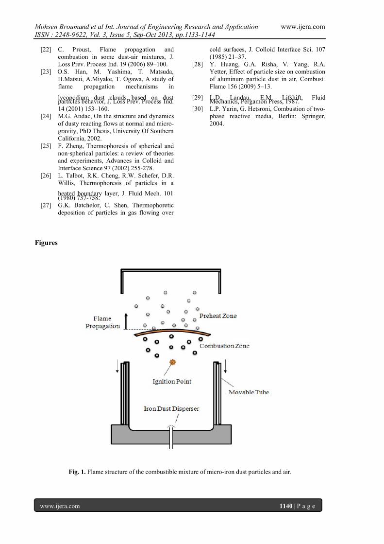
illustrated in figure (1). Utilizing such combustion
chamber has several advantages as shown by Sun etal. [6-9] and Han et al. [23].
II. Mathematical modeling 2.1. Dynamic equations of parti cles
The motion equation of a spherical particle
relative to an infinite, stagnant and viscous fluid was
first developed by Basset [24]. For a moving fluid,
Basset's equation can be expressed
as:
t
t
F p
F p
F p
F
p F F
p
F p p
p
p
p
t
d
d
vvd d
dt
vvd d
dt
dvd vvd
dt
dvd
0
2/1
2/12
333
2
3
62
1
63
6
(1)
Where pd is the particle diameter, v the velocity,
the density,
the fluid viscosity, t
the time and
subscripts p and F
designate the particle and the
fluid respectively. The term on the left indicates theaccelerating force applied to the particle and the right
one shows the Stokes drag force, the pressuregradient force on fluid, fluid resistance to
accelerating sphere and drag force associated with
unsteady motion respectively. In addition to the
above-mentioned forces, there might be other forces
acting on the particle such as gravitation, centrifugal,
electromagnetic, thermophoretic, diffusiophoretic,and Brownian forces, etc.
In general, in gas and metal particle
mixtures, the forces involving F compared to the
forces involving p can be ignored. This is because
the particles density is many orders of magnitude
larger than the fluid density. In most combustion
environments, centrifugal and electromagnetic forces
do not exist. And in the absence of high
concentration gradients in the system,
diffusiophoretic force can also be ignored. However,
the thermophoretic forces and gravitation forces have
major effects on the motion of particles and a deeper study is felt required. The Brownian forces in system
are resulted from the collisions between the fluid
molecules and fine particles, which play a crucial role
for the small particles and are usually dominated by
other forces. As a result, the following equation isobtained for the combustion of metal dust particles.
T BG D
p
p F F F F dt
dvm
(2)
In which p p mv , are the particle velocity and mass.
Besides, ,,, G BT F F F and D F are thermophoretic,
buoyancy, gravitation and drag forces respectively.
These forces will be described in more detail in the
following sections.
2.1.1. Drag force
This force is resulted from the difference between the velocity of a particle and the gases in its
7/27/2019 Gl 3511331144
http://slidepdf.com/reader/full/gl-3511331144 3/12
Mohsen Broumand et al Int. Journal of Engineering Research and Application www.ijera.com ISSN : 2248-9622, Vol. 3, Issue 5, Sep-Oct 2013, pp.1133-1144
www.ijera.com 1135 | P a g e
surrounding environment. In general, the drag
coefficient depends on the shape and the orientation
of a particle with respect to the flow and must be
calculated considering the flow parameters such as
Reynolds number, Mach number and whether the
flow is laminar or turbulent. It should be mentioned
that in small Reynolds numbers, the drag forceapplied to the particles is proportional to the size of
the particles and the difference between the velocityof the flame and the particle. At low Reynolds
numbers, the drag force on a rigid sphere of radius
pr is given by Stokesian approximation as:
f p p D vvr F 6
(3)
Where and f v are gas viscosity and the flame
propagation velocity in the mixture of micro-particle
and the air.
2.1.3. Gravitati on and buoyancy for ces The gravitation and Buoyancy forces
applied to spherical particles are presented via thefollowing equation.
g r F F g p p BG 3
3
4
(4)
Where p and , g
are the particle and gas
densities respectively, and g
is the gravitational
acceleration vector.
2.1.2. Thermophoretic force
Thermophoretic is a term describing a phenomenon where small particles such as soot
particles, aerosol and so on, when suspended in a gas
with temperature gradient, can feel this force in the
opposite direction to the temperature gradient. This
phenomenon was first proved by Aitken, with a series
of experiments in 1884, that the dust particles must
have been driven away from the heated surface bydifferential bombardment of the gas molecules [25].
The thermophoretic force should be investigated in
most reacting dusty flows, in which particles with
diameters of the order of microns or less are flowing
against substantial temperature gradients. Talbot et
al. [26] presented an acceptable equation incontinuum limit of small Knudson numbers for the
spherical particles which is presented as:
u g g p
g s
pT T
T
k k
k C d F
26 2
(5)
In which T is the temperature gradient in
the mixture of micro-iron particles and gas and uT is
the mean gas temperature of the surrounding region
of the particles and equal to the temperature of the
unburned mixture. In addition, p g s k k C ,, are the
temperature jump coefficient and thermal
conductivity for the gas and particles respectively.
The value 1.147 is suggested for sC by Batchelor
and Shen [27].
2.2. Thermal equations
In order to obtain flame propagationcharacteristics such as flame velocity and
temperature, an analytical model is developed taking
the mass and energy conservation equations into
account. Besides, to calculate the thermophoretic
force, temperature profile of the micro-iron particles-
air mixture is needed. In this study, the proposedmodel is based on a model that has been previously
developed by Goroshin et al. [15] and Huang et al.
[28] for aluminum dust particles. In addition to the
fact that the model has demonstrated good correlation
with results obtained using suspensions of small
particle sized aluminum dust in air, the model
predictions have a good agreement to the
experimental results for iron dust particles as shown
by Tang et al. [16,21]. In the model, following
simplifying assumption are made: 1) The temperature
for the particles and the gas is the same and as aresult of that, there is no heat transfer between them.
2) Particle distribution for iron in the air is uniform.
3) Biot number is so small that the temperature inside
the particle is taken to be uniform. 4) Heat transfer by
radiation is ignored. 5) Coefficient of conduction,
heat capacity of the mixture, density and burningtime for the particles are constant. With these
approximations, the governing mass and energy
equations describing the preheat and combustion
zones become linear and can be solved in closedform. For the steady, one-dimensional, and laminar
flame propagation, the mass and energy conservationequations are generally expressed as:
f uv ρ ρv
(6)
qw x
T λ
xcT
x ρv
.
(7)
Where.
w is the rate of reaction, q the heat of
reaction, f v the flame velocity. Also, ρ , v , T are
the mixture density, velocity, and temperature,
respectively.To solve the conservation equations,
structure of flame propagation through iron dust particles is divided into two zones; a preheat zone,
and a combustion zone. These equations are solved in
these two regions using suitable boundary conditions,
and since convection heat losses to the walls is
ignored because of the special design of combustion
chamber, it is assumed the flame temperature gets
stable after its maximum value. Accordingly, the
boundary conditions can be expressed as:
u Ι T T , x
ΙΙ Ι T T , x 0
7/27/2019 Gl 3511331144
http://slidepdf.com/reader/full/gl-3511331144 4/12
Mohsen Broumand et al Int. Journal of Engineering Research and Application www.ijera.com ISSN : 2248-9622, Vol. 3, Issue 5, Sep-Oct 2013, pp.1133-1144
www.ijera.com 1136 | P a g e
x
T
x
T , x ΙΙ Ι
0
0
x
T , x ΙΙ
(8)
Here uT represents the temperature of unburnedmixture, and Ι T , ΙΙ T show the temperature in the
preheat and combustion zones respectively. Also,
0 x indicates the leading edge of the combustion
zone. III. Analytical solution
3.1. Thermal equations
Introduce the non-dimensional variables and
parameters as follows:
uiu
ud
c f u
c f ui
u
T T c
qC
cvS
v
x X
T T
T T
,
2
2 ,,,
(9)
Where iT represents the ignition
temperature of micro-iron particles, and c is the
particle burning time. Also, ud C , is the initial mass
concentration of particulate fuel and equal to the
concentration of particles in the unburned mixture.
2/1
cu
f
c
vS
is the dimensionless flame
velocity, and is the dimensionless heat release. In
this model, rate of reaction
)exp()(.
X τ C w cd,u is taken into account
according to the amount of fuel available (initial
mass concentration of fuel), and the total particle
burning time which is assumed to be equal to the
burning time of a single particle [15]. Substituting the
above parameters into equations (7) and (8), we
obtain the following non-dimensional equations and
boundary conditions for the two different zones.
Preheat zone:
02
2
2
X
θ
S X
θ Ι Ι
(10)
Combustion zone:
0)exp(22
2
2
X γS
X
θ S
X
θ ΙΙ ΙΙ
(11)
Dimensionless boundary conditions are:
0 Ι θ , X
(12)
ΙΙ Ι , X 0
x x , X ΙΙ Ι
0
0 x
, X ΙΙ
By solving thermal equations (10) and (11),
applying suitable boundary conditions (12),
dimensionless temperature equations as a function of
dimensionless space can be calculated in two zones.
Preheat zone:
)exp(1
2
2 X S S
γ
X θ Ι
(13)
Combustion zone:
)exp(12
2
X S
γS X θ ΙΙ
(14)
At the leading edge of the combustion
zone 0 x , the particles reach their ignition
temperature iT . Taking this condition into
temperature profile equations leads to the following
correlation for the flame velocity.
12
uiud,u
cu f T T c
qC
cv
(15)
The last equation agrees fairly well with the
general remarks in literature [29,30], where for a
flame propagating via molecular transport of heat,
dimensional analysis suggested that the propagation
velocity f v should depend on the thermal diffusivity
and the characteristic combustion time c as
follows: c f v ~2
.
3.2. Dynamic equations of part icl es
In order to solve the dynamic equations, thedistance between the particles and the leading edge of
the flame is presented by f prel x x x , and the
velocity of the particles toward the edge of the flame
with f prel vvv . Substituting equations (3), (4)
and (5) into equation (2), and by applying theabovementioned relative position and velocity, the
following differential equations are achieved to
calculate particles velocity.
g r F dt
dxr
dt
dxr
p
g
p pT
rel
p
rel
p p
1
3
46
3
4 3
2
2
3
(16)
As the value of thermophoretic force is
proportional to the temperature gradient according to
equation (5), and considering the temperature profile,
obtained in the preheat zone from equation (13), itcan be calculated as follows:
x
v
S
S
γS
v
T T
T k k
k C d x F
f u f
ui
u g g p
g s
pT )(exp
1)(
1
26)(
2
2
22
(17)
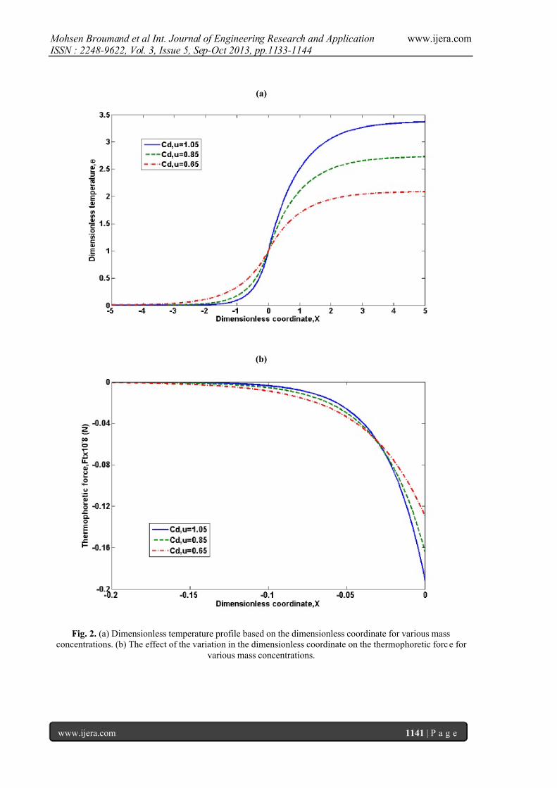
Using equations (13) and (14), the
temperature profile is depicted in figure (2a). As
observed in figure (2a), maximum value of thetemperature gradient is at the edge of the
7/27/2019 Gl 3511331144
http://slidepdf.com/reader/full/gl-3511331144 5/12
Mohsen Broumand et al Int. Journal of Engineering Research and Application www.ijera.com ISSN : 2248-9622, Vol. 3, Issue 5, Sep-Oct 2013, pp.1133-1144
www.ijera.com 1137 | P a g e
flame 0 x . Consequently, thermophoretic force is
significant only at this location and the amount of this
force tends to zero by getting farther than the edge of
the flame, figure (2b). Since the concentration which
the edge of flame senses plays a key role during the
flame propagation, it is assumed that the value of
thermophoretic force has a constant value, and itequals its value at the edge of the flame. As a result,
by solving the ordinary differential equation (16), the
correlation of relative position as a function of time is
acquired as:
t g
r
r
F ct
r c x
p
g p p
p
T
p p
rel
1
9
2
62
9exp
2
221
(18)
Moreover, the equation of relative velocity
of the particles as a function of time is obtained using
the coming approach:
g
r
r
F t
r r c
dt
dxv
p
g p p
p
T
p p p p
rel rel
1
9
2
62
9exp
2
92
221
(19)
To obtain the constants 1c and 2c , two time
conditions are required. In fact, particles are only
influenced by gravitation and Buoyancy forces at a
certain distance t L , and move downward with the
constant velocity t U . In fact, t L
is a characteristic
length of a zone in front of the flame in which particles have not sensed the effects of the flame yet.
The amount of t U is calculated by balancing drag,
Buoyancy and gravitation forces as:
g p
p
t
gr U
2
9
2
(20)
Supposing that the particles, at the initial
moment, are at the distance t L from the edge of the
flame, two initial conditions can be expressed as:
t rel Lt x 0 (21)
f t rel vU t v 0
(22)
By applying the initial condition (22) in
equation (19), the value of 1c is gained this way:
)6(9
22
1
p
T f
p p
r
F v
r c
(23)
Ultimately, by inserting equation (23) in
equation (18) and applying the initial condition (21),
the value of 2c can be obtained using the followingequation.
)6(9
2 2
2
p
T f
p p
t r
F v
r Lc
(24)
3.3. Mass concentr ation of parti cles
By determining the position and velocity of
the particle as a function of time for iron particles, the
number density profile of particles in the preheat
zone can be calculated. In order to reach the number
density profile of particles in front of the flame, a
small enough control volume above the leading edge
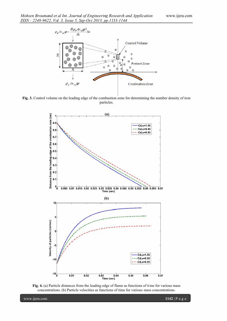
of combustion zone is assumed, figure (3). This
volume control is located at the distance value of x from the edge of the flame and has the height value
of x and area value of A . Supposing that the
particles move vertically along with the duct axes,
when passing the volume control, the variation in the
number density of particles can be calculated by balancing particle mass fluxes.
For the condensed phase, fractional volume
is determined as the proportion of particles volume tothe total volume. For the condensed phase of
particles, the fractional volume is defined as
p p s pd mnC .
Where d C is the mass
concentration of particulate fuel, and sn is the
number density of particles (i.e., the number of
particles in the volumetric unit). The particles mass
flux passing through a volume control is equal to
rel p
Av and taking x as the height of volume
control, flux variation at x axis is:
x A x
v x
x
Av rel prel p
(25)
In which f prel vvv is the relative
velocity of the particles which is determined in the
equations (19). The accumulation rate of particles
is x At p , and since there is no mass
reduction in the iron particle combustion as a result
gasification, the mass equation for the volume control
is expressed as follows:
x A x
v x A
t
rel p p
(26)
Solving the above equation with the
boundary condition ~ t L x , the values
for the ratio of the fractional volume and ratio of number density of particles would be as follows:
rel
rel
s
s
v
v
n
n ~
~~
(27)
Where p p s pud mnC ψ ~~, . Also,
sn~ , and rel v~ are the number of particles in the
7/27/2019 Gl 3511331144
http://slidepdf.com/reader/full/gl-3511331144 6/12
Mohsen Broumand et al Int. Journal of Engineering Research and Application www.ijera.com ISSN : 2248-9622, Vol. 3, Issue 5, Sep-Oct 2013, pp.1133-1144
www.ijera.com 1138 | P a g e
volumetric unit and the relative velocity of particles
at t L x . Therefore, actual concentration of the
iron dust cloud (i.e., the concentration which the edge
of flame senses during flame propagation) can bewritten as follow:
g r
r
F t
r r c
C vC
p
g p p
p
T
p p p p
ud rel
act d
1
9
2
62
9exp
2
9
.~
2
1221
,
,
(28)
Where 1t is the time when particles reach
the leading edge of flame 0 x , and it can be
obtained from equation (18). Also, 1c is gained from
equation (23).
IV. Results and discussionThe major goal of this article is to study the
dynamic behavior of micro-iron particles in the
preheat zone and its impact on the flame propagation
characteristics. The preheat zone is affected by the
combustion zone and causes the difference in the
velocity of the two phases of solid and gas. This
difference can change number density of particles at
the leading edge of the combustion zone. The
analytical results have been compared with the
experimental work done by Sun et al. [7,8].
Figure (4a) illustrates the distance of the
iron particles from the leading edge of the
combustion zone through time using equation (18).
At 0t the position of particles are t L , and as it is
obvious, with increasing the mass concentration of
micro-iron particles, the time for the particles to
reach the edge of the flame decreases. It is worth
noting that in the experimental study carried out for
determining the density and velocity profiles of iron
particles by Sun et al. [8], the quantity of t L was
reported around 10 mm at the constant
scmv f /25 and3
, 05.1 mkg C ud .
Figure (4b) displays variation in the particles velocity
for different mass concentration using equation (19).According to the diagram, as the particles move
closer to the edge of the flame considering the effect
of the combustion zone, their velocity decreases from
about scmU t /5.11 to zero in the direction
opposite to the flame propagation direction. And
then, their velocity increases until they reach the
leading edge of the flame. The flame velocities
required for equations are determined from equation(15).
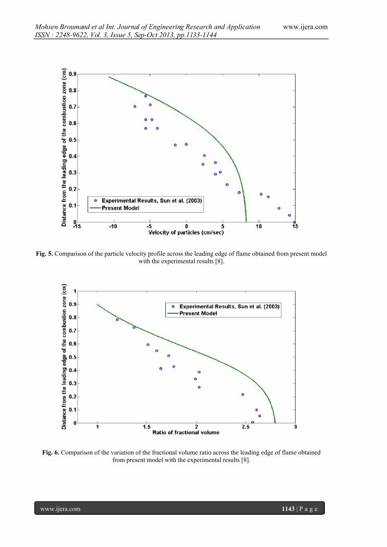
The velocity profile for the micro-iron
particles for 3
, 051 kg/m.C ud is described in
figure (5) which indicates that the velocity of the
particles can change by the distance to the leading
edge of the flame. It should be mentioned that,
particles before reaching the characteristic length t L
move with constant velocity t U . As soon as they
reach the certain distance t L , their velocity decline
and tend to zero. As they pass approximately half of
the length, they take the opposite direction and their
velocity increases until they reach the leading edge of
the flame. The results are compared with previous
experimental results [8].
In figure (6), the ratio of fractional volume
~based on the distance from the edge of the
flame is depicted using equation (27). As expected,
the relative velocity between the particles and the
flame results in the accumulation of the particles in
the preheat zone and especially on the edge of the
flame. This process makes the flame move in a
denser environment and has effects on the reaction
rate of particles and flammability limit in thismixture. The results are compared with previous
experimental results [8].
Table (1) is reported the value of most
significant parameters involved in the laminar flame
propagating in suspensions of iron dust in air, and thecorresponding actual concentration, obtained by
virtue of equation (28). In this table, 1t is obtained
from equation (18). Besides, values of flame velocity
f v , and actual flame velocity act f v , are gained by
putting ud C , , and act d C , in equation (15). It is
worth mentioning that ud act d C C ,, is a
correction factor which indicates that flame moves in
a denser environment compared to the initial
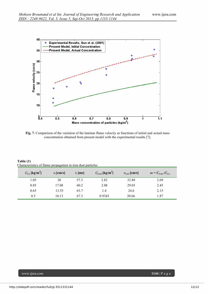
condition.Figure (7) illustrates the effect of the mass
concentration of particles on the laminar flame
velocity for the iron dust cloud. In general, trends of
the f v , and act f v , are slightly upward; In fact, with
a rise in the concentration of the dust cloud from
about 0.53kg/m to about 1.05
3kg/m , the flame
propagates more rapidly. The calculations were
accomplished by putting 2.2 as an averageamount of the correction factor. It can be easily
observed that the deviation between calculated value
and experimental data result [7], can be considered
adequate for act f v , in comparison with f v . Hence,
ac t d C , seems more useful than ud C , to obtain more
realistic estimates of the laminar flame velocity
propagating in suspensions of iron dust in air.
V. ConclusionsAs the analytical results of the present study
show, contrary to the developed theory of
homogeneous gas flames, flame propagation in the
micro-iron dust particles is largely under the
7/27/2019 Gl 3511331144
http://slidepdf.com/reader/full/gl-3511331144 7/12
Mohsen Broumand et al Int. Journal of Engineering Research and Application www.ijera.com ISSN : 2248-9622, Vol. 3, Issue 5, Sep-Oct 2013, pp.1133-1144
www.ijera.com 1139 | P a g e
influence of particle motions as well as heat and mass
transfer. At the time of flame propagation, the
velocity of the gas increases near the combustion
zone as a result of expansion, and leads to creation of
a slip between two phases. Consequently, the
particles concentration in the preheat zone is affected
and results in the change in the flame velocity.Results show the mass concentration of the particles
in the preheat zone changes and gets larger until itreaches the maximum value in the leading edge of the
flame. It can be observed that actual mass
concentration, presented in this paper, seems to be
much more useful than initial mass concentration of
the mixture to obtain more realistic estimates of the
flame velocity propagating in suspensions of micro-iron dust particles in air.
This study proves the importance of
conducting more researches on the interphase
slipping in a heterogeneous combustion, which
directly affects the flame propagation characteristicsin a heterogeneous medium. This phenomenon seemsto be one of the main reasons why the lower
flammability limit of dust cloud flame is much
smaller than that of gas fuel flame, and further effort
is clearly needed to develop the heterogeneous
combustion theory. It is worth noticing that the
present approach can be easily adapted to investigate
the flame propagation characteristics of different dust
clouds such as aluminum, magnesium, lycopodium,
woods and biomass.
References
[1] G. Joseph, CSB Hazard Investigation Team,Combustible dusts: A serious industrial
hazard, J. Hazard. Mater. 142 (2007) 589-
591.
[2] O. Dufaud, L. Perrin, M. Traore, S.
Chazelet, D. Thomas, Explosions of
vapour/dust hybrid mixtures: a particular
class, Powder Technology 190 (2009) 269-
273.[3] A. Garcia-Agreda, A. Di Benedetto, P.
Russo, E. Salzano, R. Sanchirico, Dust/gas
mixtures explosion regimes, Powder
Technology 205 (2011) 81-86.
[4] W. Gao, R. Dobashi, T. Mogi, J. Sun, X.Shen, Effects of particle characteristics onflame propagation behavior during organic
dust explosions in a half-closed chamber, J.
Loss Prev. Process Ind. 25 (2012) 993-999.
[5] D.B. Beach, A.J. Rondinone, B.G. Sumpter,
S.D. Labinov, R.K. Richards, Solid-state
combustion of metallic nanoparticles: new
possibilities for an alternative energy carrier,
J. Energy Resour. Technol. 129 (2007) 29-
32.
[6] J.H. Sun, R. Dobashi, T. Hirano,
Combustion behavior of iron particles
suspended in air, Combust. Sci. Technol.150 (2000) 99 – 114.
[7] J.H. Sun, R. Dobashi, T. Hirano,
Temperature profile across the combustion
zone propagating through an iron particle
cloud, J. Loss Prev. Process Ind. 14 (2001)
463 – 467.
[8] J.H. Sun, R. Dobashi, T. Hirano,
Concentration profile of particles across aflame propagating through an iron particle
cloud, Combust. Flame 134 (2003) 381 – 387.[9] J.H. Sun, R. Dobashi, T. Hirano, Velocity
and number density profiles of particles
across upward and downward flame
propagating through iron particle clouds, J.
Loss Prev. Process Ind. 19 (2006) 135 – 141.
[10 K.L. Cashdollar, Overview of dustexplosibility characteristics, J. Loss Prev.
Process Ind. 13 (2000) 183 – 199.
[11] K.L. Cashdollar, I.A. Zlochower, Explosion
temperatures and pressures of metals and
other
elemental dust clouds, J. Loss Prev.Process Ind. 20 (2007) 337 – 348.
[12] P. Kosinski, R. Nyheim, V. Asokan, T.
Skjold, Explosions of carbon black and
propane hybrid mixtures, J. Loss Prev.
Process Ind. 26 (2013) 45-51.
[13] R.H. Essenhigh, J. Csaba, The thermal
radiation theory for plane flame propagation
in coal dust clouds, Symp. (International)
Combust. 9 (1963) 111-125. [14] K. Seshadry, A.L. Berlad, V. Tangirala, The
structure of premixed particle-cloud flames,
Combust. Flame 89 (1992) 333 – 342.
[15] S. Goroshin, M. Bidabadi, J.H.S. Lee,Quenching Distance of Laminar Flame in
Aluminum Dust Clouds, Combust. Flame
105 (1996) 147 – 160.
[16] F.D. Tang, S. Goroshin, A. Higgins, J. Lee,
Flame propagation and quenching in irondust clouds, Proc. Combus. Inst. 32 (2009)
1905 – 1912.
[17] M. Broumand, M. Bidabadi, Modeling
combustion of micron-sized iron dust
particles during flame propagation in avertical duct, Fire Safety Journal 59 (2013)
88 – 93.
[18] P.B. Vainshtein, R.I. Nigmatulin,Combustion of gas- particle mixture, Prikl.
Mech.Tech. Phys. (in Russian) 4 (1971) 19-
33.
[19] E.L. Dreizin, V.K. Hoffman, Constant
pressure combustion of aerosol of coarse
magnesium particles in microgravity,
Combust. Flame 118 (1999) 262 – 280.
[20] R.A. Yetter, G.A. Risha, S.F. Son, Metal
particle combustion and nanotechnology,
Proc. Combust. Inst. 32 (2009) 1819 – 1838. [21] F.D. Tang, S. Goroshin, A. Higgins, Modes
of particle combustion in iron dust flames,
Proc. Combust. Inst. 33 (2011) 1975 –
1982.
7/27/2019 Gl 3511331144
http://slidepdf.com/reader/full/gl-3511331144 8/12
Mohsen Broumand et al Int. Journal of Engineering Research and Application www.ijera.com ISSN : 2248-9622, Vol. 3, Issue 5, Sep-Oct 2013, pp.1133-1144
www.ijera.com 1140 | P a g e
[22] C. Proust, Flame propagation and
combustion in some dust-air mixtures, J.
Loss Prev. Process Ind. 19 (2006) 89 – 100.
[23] O.S. Han, M. Yashima, T. Matsuda,
H.Matsui, A.Miyake, T. Ogawa, A study of
flame propagation mechanisms in
lycopodium dust clouds based on dust particles behavior, J. Loss Prev. Process Ind.
14 (2001) 153 – 160. [24] M.G. Andac, On the structure and dynamics
of dusty reacting flows at normal and micro-
gravity, PhD Thesis, University Of Southern
California, 2002.
[25] F. Zheng, Thermophoresis of spherical and
non-spherical particles: a review of theoriesand experiments, Advances in Colloid and
Interface Science 97 (2002) 255-278.
[26] L. Talbot, R.K. Cheng, R.W. Schefer, D.R.
Willis, Thermophoresis of particles in a
heated boundary layer, J. Fluid Mech. 101(1980) 737-758.
[27] G.K. Batchelor, C. Shen, Thermophoretic
deposition of particles in gas flowing over
cold surfaces, J. Colloid Interface Sci. 107
(1985) 21 – 37.
[28] Y. Huang, G.A. Risha, V. Yang, R.A.
Yetter, Effect of particle size on combustion
of aluminum particle dust in air, Combust.
Flame 156 (2009) 5 – 13.
[29] L.D. Landau, E.M. Lifshift, FluidMechanics, Pergamon Press, 1987.
[30] L.P. Yarin, G. Hetsroni, Combustion of two- phase reactive media, Berlin: Springer,
2004.
Figures
Fig. 1. Flame structure of the combustible mixture of micro-iron dust particles and air.
7/27/2019 Gl 3511331144
http://slidepdf.com/reader/full/gl-3511331144 9/12
Mohsen Broumand et al Int. Journal of Engineering Research and Application www.ijera.com ISSN : 2248-9622, Vol. 3, Issue 5, Sep-Oct 2013, pp.1133-1144
www.ijera.com 1141 | P a g e
(a)
(b)
Fig. 2. (a) Dimensionless temperature profile based on the dimensionless coordinate for various mass
concentrations. (b) The effect of the variation in the dimensionless coordinate on the thermophoretic force for
various mass concentrations.
7/27/2019 Gl 3511331144
http://slidepdf.com/reader/full/gl-3511331144 10/12
Mohsen Broumand et al Int. Journal of Engineering Research and Application www.ijera.com ISSN : 2248-9622, Vol. 3, Issue 5, Sep-Oct 2013, pp.1133-1144
www.ijera.com 1142 | P a g e
Fig. 3. Control volume on the leading edge of the combustion zone for determining the number density of iron particles.
(a)
(b)
Fig. 4. (a) Particle distances from the leading edge of flame as functions of time for various mass
concentrations. (b) Particle velocities as functions of time for various mass concentrations.
7/27/2019 Gl 3511331144
http://slidepdf.com/reader/full/gl-3511331144 11/12
Mohsen Broumand et al Int. Journal of Engineering Research and Application www.ijera.com ISSN : 2248-9622, Vol. 3, Issue 5, Sep-Oct 2013, pp.1133-1144
www.ijera.com 1143 | P a g e
Fig. 5. Comparison of the particle velocity profile across the leading edge of flame obtained from present model
with the experimental results [8].
Fig. 6. Comparison of the variation of the fractional volume ratio across the leading edge of flame obtained
from present model with the experimental results [8].
7/27/2019 Gl 3511331144
http://slidepdf.com/reader/full/gl-3511331144 12/12
Mohsen Broumand et al Int. Journal of Engineering Research and Application www.ijera.com ISSN : 2248-9622, Vol. 3, Issue 5, Sep-Oct 2013, pp.1133-1144
www.ijera.com 1144 | P a g e
Fig. 7. Comparison of the variation of the laminar flame velocity as functions of initial and actual mass
concentration obtained from present model with the experimental results [7].
Table (1)
Characteristics of flame propagation in iron dust particles
C d,u [kg/m3] v f [cm/s] t 1 [ms] C d,act [kg/m
3] v f,act [cm/s] ω = C d,act /C d,u
1.05 20 57.3 2.82 32.88 2.69
0.85 17.08 60.2 2.08 29.03 2.45
0.65 13.55 63.7 1.4 24.6 2.15
0.5 10.13 67.3 0.9343 20.66 1.87