facultad de ingeniería de sistemas y -...
TRANSCRIPT


2
Facultad de Ingeniería de Sistemas y
Electrónica
Carrera Profesional de Ingeniería Mecatrónica
Informe de Suficiencia Profesional para optar el Título
Profesional de Ingeniero Mecatrónico
“SISTEMA DE CONTROL DE UNA PLANTA
DE PRODUCCIÓN DE ASFALTO”
Bachiller:
Max Antonio Allccaco Córdova
Lima – Perú
2016

3
A mi familia por darme todo el apoyo y soporte
necesario para seguir adelante.

4
AGRADECIMIENTOS
Me gustaría agradecer el presente informe de suficiencia personal en primer lugar a mi
familia, a mis padres y hermano por haberme apoyado y guiado sin duda alguna durante
cada etapa de mi vida, en mi desarrollo personal y profesionalmente.
A la Universidad Tecnológica del Perú por impulsar mi crecimiento profesional.

5
RESUMEN
El proyecto consiste en la automatización de una planta de producción de asfalto,
desarrollo de un sistema de control para el proceso, a lo largo del proceso se colocaran
instrumentos de medición y se emplearan los mismos motores para mejorar la producción.
El informe será divido en 4 capítulos de los cuales en el tercer capítulo se abordará todo el
tema del desarrollo de la ingeniería para el proyecto, en esta parte se detallará el proceso
de selección para poder diseñar un gabinete de control, los planos respectivos para el
proyecto y el desarrollo de la programación.
En el capítulo 4 se mostrará los resultados obtenidos de la simulación del programa
desarrollado en el capítulo anterior, es decir se muestra el resultado final de las pantallas
que se han desarrollado para el proceso.

6
UNIVERSIDAD TECNOLÓGICA DEL PERÚ
PROGRAMA ESPECIAL DE TITULACIÓN
DECLARACION JURADA
Yo, Max Antonio Allccaco Cordova , con DNI: 71905337 y código de matrícula 0710861,
bachiller de la carrera de Ingeniería Mecatrónica, con el INFORME SE SUFICIENCIA
PROFESIONAL (ISP) titulado: “Sistema de control de una planta de producción de asfalto”.
Declaro bajo juramento que:
1. El informe ISP y la solución presentada en él es de mi autoría.
2. Toda la información utilizada para el desarrollo del ISP es original y real.
Lima, 03 de Agosto del 2015
………………………………………………………..….. Allccaco Cordova, Max Antonio.

7
CONTENIDO
AGRADECIMIENTOS ............................................................................................... 4
RESUMEN ................................................................................................................ 5
CONTENIDO ............................................................................................................ 7
ÍNDICE DE TABLAS ............................................................................................... 10
ÍNDICE DE FIGURAS ............................................................................................. 11
INTRODUCCIÓN .................................................................................................... 12
CAPÍTULO 1 ........................................................................................................... 13
ASPECTOS GENERALES ............................................................................ 13
1.1. DEFINICIÓN DEL PROBLEMA ............................................................. 13
1.2. DESCRIPCIÓN DEL PROBLEMA ......................................................... 14
1.3. FORMULACIÓN DEL PROBLEMA........................................................ 15
1.4. DEFINICIÓN DE OBJETIVOS ............................................................... 15
1.4.1. OBJETIVO GENERAL ................................................................. 15
1.4.2. OBJETIVOS ESPECÍFICOS ....................................................... 15
1.5. ALCANCES Y LIMITACIONES .............................................................. 16
1.6. JUSTIFICACIÓN ................................................................................... 16
1.7. ESTADO DEL ARTE ............................................................................. 17
CAPITULO 2 ........................................................................................................... 18
MARCO TEÓRICO ........................................................................................ 18
2.1. ASFALTO .............................................................................................. 18
2.2. DIAGRAMA DE FLUJO DEL PROCESO ............................................... 18
2.2.1. ALMACENAMIENTO DEL ASFALTO EN FRIO PEN 60-70 ........ 20
2.2.2. PROCESAMIENTO DE ARIDOS ................................................. 20
2.2.2.1. TOLVAS DE ARIDOS .......................................................... 20
2.2.2.2. FAJAS TRANSPORTADORAS DE ARIDOS ....................... 20
2.2.2.3. SECADOR ROTATORIO ..................................................... 20
2.2.2.4. ZARANDA ........................................................................... 21
2.2.3. PROCESO DE MEZCLADO Y ELABORACION .......................... 21
2.3. AUTOMATIZACION INDUSTRIAL......................................................... 21
2.3.1. NIVELES DE AUTOMATIZACION INDUSTRIAL ................................ 21
2.3.2. METODOS DE CONTROL DE UN PROCESO .................................. 23

8
2.3.2.1. CONTROL PID ............................................................................ 23
2.3.2.2. CONTROL DIFUSO .................................................................... 25
2.4. COMUNICACIÓN INDUSTRIAL ............................................................ 26
2.4.1. PROTOCOLOS DE COMUNICACIÓN ........................................ 26
2.5. SISTEMAS SCADA ............................................................................... 28
2.6. CONTROLADOR LÓGICO PROGRAMABLE (PLC) ............................. 29
CAPÍTULO 3 ........................................................................................................... 30
DESARROLLO DE LA SOLUCIÓN ............................................................... 30
3.1. INSPECCIÓN TECNICA DE LA PLANTA CHAMONTE ......................... 30
3.1.1. INSPECCIÓN ELÉCTRICA ................................................................ 30
3.1.1.1. ZONA DE TOLVAS ..................................................................... 30
3.1.1.2. ZONA DE TANQUES .................................................................. 32
3.1.1.3. ZONA DE MEZCLADOR ............................................................. 34
3.1.1.4. LÍNEA NEUMÁTICA – BOMBA DE AIRE .................................... 37
3.1.1.5. ZONA DEL TABLERO GENERAL ELÉCTRICO DE LOS MOT ... 38
3.1.2. INSPECCION MECANICA ................................................................. 39
3.1.2.1. ZONA DE TANQUES .................................................................. 39
3.1.2.2. ZONA DE MEZCLADOR ............................................................. 41
3.1.3. CONCLUSIONES DE LA INSPECCION ............................................. 42
3.2. ARQUITECTURA DE CONTROL .......................................................... 43
3.3. LISTA DE INSTRUMENTOS ................................................................. 44
3.4. SELECCIÓN DE INSTRUMENTACION ................................................ 47
3.4.1. SENSOR DE NIVEL ........................................................................... 48
3.4.2. SENSOR DE TEMPERATURA........................................................... 49
3.4.3. VALVULA DE CONTROL ................................................................... 49
3.4.4. ACTUADOR DE LA VALVULA ........................................................... 50
3.4.5. ELECTROVALVULA .......................................................................... 51
3.5. DIAGRAMA DE FLUJO DEL PROCESO Y P&ID .................................. 52
3.6. DISEÑO DE GABINETE DE CONTROL ................................................ 52
3.6.1. CONTROLADOR LÓGICO PROGRAMABLE (PLC) ................... 52
3.6.2. PROTECTOR SOBRE TENSION ................................................ 54
3.6.3. BORNERAS FRONTERA ............................................................ 54
3.6.4. OTROS MATERIALES INTERNOS ............................................. 55
3.6.5. GABINETE .................................................................................. 55
3.7. PROGRAMACIÓN DE PLC ................................................................... 56
3.7.1. CONFIGURACIÓN I/O ................................................................ 56
3.7.2. CONFIGURACIÓN DE TAGS DE INSTRUMENTOS .................. 57

9
3.7.3. CONFIGURACIÓN DE SUBRUTINAS ........................................ 58
3.7.3.1. SUBRUTINA: CONTROL BOMBAS .................................... 59
3.7.3.2. SUBRUTINA: CONTROL MOTORES .................................. 60
3.7.3.3. SUBRUTINA: CONTROL TEMPERATURA DE TANQUES . 61
3.7.3.4. SUBRUTINAS: MAPEO NIVEL/TEMPERATURA DE TAN .. 62
3.7.3.5. SUBRUTINA: SEÑALES DE MOTORES ............................. 63
CAPÍTULO 4 ........................................................................................................... 65
RESULTADOS .............................................................................................. 65
4.1. NUEVO CONTROL DEL PROCESO ..................................................... 65
4.1.1. USUARIOS DE CONTROL DE LA PLANTA ....................................... 66
4.1.2. MONITOREO DE VARIABLES ........................................................... 66
4.1.3. VISUALIZACION DE ALARMAS ........................................................ 67
4.2. VENTANA EMERGENTE DE TENDENCIAS ........................................ 68
4.3. OPERACIÒN DE LOS MOTORES Y VALVULAS .................................. 68
4.4. PRESUPUESTO ................................................................................... 70
4.4.1. FLUJO DE CAJA ......................................................................... 70
CONCLUSIONES ................................................................................................... 73
ANEXO 1: plano arquitectura de control ........................................................ 74
ANEXO 2: plot plan ........................................................................................ 75
ANEXO 3: lista de señales e instrumentos..................................................... 76
ANEXO 4: planos p&ID .................................................................................. 77
ANEXO 5: planos del gabinete de control ...................................................... 78
ANEXO 6: algorito de control desarollado en el plc ........................................ 79
GLOSARIO ............................................................................................................. 80
Bibliografía .............................................................................................................. 81

10
ÍNDICE DE TABLAS Tabla 1: Lista de Instrumentos ............................................................................. 47 Tabla 2: Disposición de componentes en el PLC ................................................. 53 Tabla 3: Características del protector de sobretensión. ....................................... 54 Tabla 4: Material del personal. ............................................................................. 70 Tabla 5: Insumos empleados para el proyecto. .................................................... 71 Tabla 6: Equipos empleados para el proyecto. .................................................... 71 Tabla 7: Presupuesto material humano ................................................................ 72 Tabla 8: Egreso del presupuesto del proyecto ..................................................... 72
11
ÍNDICE DE FIGURAS Figura 1. Diagrama de causa y efecto .................................................................. 15 Figura 2. Diagrama de flujo del proceso ............................................................... 19 Figura 3. Pirámide de automatización .................................................................. 22 Figura 4. Diagrama de un controlador PID ........................................................... 24 Figura 5. Diagrama de un controlador difuso ....................................................... 25 Figura 6. Coexistencia de múltiples redes ............................................................ 26 Figura 7. Scada plataforma InTouch Wonderware ............................................... 28 Figura 8. Controlador marca Allen Bradley .......................................................... 29 Figura 9. Zona de Tolvas ..................................................................................... 31 Figura 10: Motor superior de la faja transportadora ............................................. 31 Figura 11: Motores vibratorios .............................................................................. 32 Figura 12: Controlador del HY WAY ..................................................................... 33 Figura 13: Controlador del HY WAY ..................................................................... 33 Figura 14: Motores del secador ............................................................................ 34 Figura 15: Quemador del HY WAY ...................................................................... 35 Figura 16: Elevador y zaranda ............................................................................. 36 Figura 17: Motor del mezclador ............................................................................ 37 Figura 18: Bomba de aire ..................................................................................... 37 Figura 19: Tablero eléctrico de los motores vista frontal ..................................... 38 Figura 20: Tanques de almacenamiento de Pen 60-70 ....................................... 40 Figura 21: Línea del tanque de almacenamiento ................................................. 41 Figura 22: Lina neumática .................................................................................... 42 Figura 23. Resumen de la arquitectura de control ................................................ 43 Figura 24: Sensor 5900S .................................................................................... 48 Figura 25: Sensor de temperatura Rosemount ................................................... 49 Figura 26: Válvula de control Honeywell V5094A, B ........................................... 50 Figura 27: Actuador eléctrico lineal de válvula ML7420A/ML7425A,B ................. 51 Figura 28: Electroválvula serie 3 de 5/2 vias ........................................................ 51 Figura 29: PLC Controllogix del gabinete de control. ........................................... 52 Figura 30: Redundancia del PLC Controllogix...................................................... 53 Figura 31: Configuración de módulos ................................................................... 57 Figura 32: Configuración de tags. ........................................................................ 58 Figura 33: Configuración de subrutinas ................................................................ 59 Figura 34: Subrutina: Control bombas .................................................................. 60 Figura 35: Subrutina: Control motores ................................................................. 61 Figura 36: Subrutina: Control temperatura de tanques ........................................ 62 Figura 37: Subrutina: Mapeo nivel/temperatura de tanques ................................. 63 Figura 38: Subrutina: Mapeo señales de motores ................................................ 64 Figura 39: Pantalla de inicio SCADA .................................................................... 65 Figura 40: Modo de ingreso.................................................................................. 66 Figura 41: Monitoreo de variables ........................................................................ 67 Figura 42: Monitoreo de alarmas .......................................................................... 67 Figura 43: Tendencia de las variables .................................................................. 68 Figura 44: Pantalla del proceso ............................................................................ 68 Figura 45: Ventana emergente Motor ................................................................... 69 Figura 46: Ventana emergente Válvula On-Off .................................................... 69 Figura 47: Ventana emergente Válvula Reguladora ............................................. 70

12
INTRODUCCIÓN
El tema que se va a desarrollar es la “Desarrollo de un sistema de control para una planta
de asfalto”, se va a elaborar una ingeniería para el proceso en el área de instrumentación
y control.
La automatización de procesos es cada vez más frecuente para mejorar la calidad de los
productos y para ahorrar costos, es siempre importante que se tenga los criterios
necesarios para el desarrollo de la ingeniería así como también seguir las normas
establecidas.
Lo que se desea con este informe es hacer un diseño de automatización del proceso y
seguir los parámetros establecidos para esto.
El desarrollo va abarcar la parte de instrumentación y control, y se desarrollará también la
simulación de la programación y la simulación del programa de supervisión que se mostrará
en resultados.

13
CAPÍTULO 1
ASPECTOS GENERALES
1.1. DEFINICIÓN DEL PROBLEMA
A lo largo de estos últimos 10 años el rubro de construcción de carreteras ha estado en
continuo desarrollo, lo cual lleva a una gran demanda de los elementos que la conforman.
Uno de los mayores problemas que afrontan las empresas es tener una capacidad de
producción alta, lo cual implica poder realizar actividades continuas de forma eficiente y
eficaz.
Actualmente nos ubicamos en una empresa constructora CHAMONTE S.A. que se dedica
a la producción de asfalto para la construcción de carreteras de tránsito.
La planta de construcción opera de manera manual, no cuenta con un sistema de control
de funcionamiento automático, es decir que los criterios de operación están dados por los
operadores, lo que deriva a un funcionamiento muy poco eficiente.
Al disponer de personal para operación de la planta, se pierden muchas horas hombre en
trabajos manuales que pueden ser reemplazados por sistemas automáticos de control.
Continuamente existen problemas de producción que reflejan perdidas en las ventas del
material final, con lo cual la rentabilidad de la empresa no es la que se tiene estimada.
14
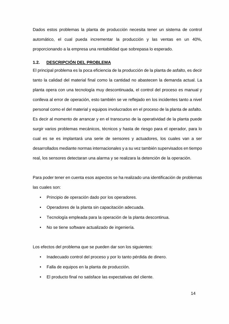
Dados estos problemas la planta de producción necesita tener un sistema de control
automático, el cual pueda incrementar la producción y las ventas en un 40%,
proporcionando a la empresa una rentabilidad que sobrepasa lo esperado.
1.2. DESCRIPCIÓN DEL PROBLEMA El principal problema es la poca eficiencia de la producción de la planta de asfalto, es decir
tanto la calidad del material final como la cantidad no abastecen la demanda actual. La
planta opera con una tecnología muy descontinuada, el control del proceso es manual y
conlleva al error de operación, esto también se ve reflejado en los incidentes tanto a nivel
personal como el del material y equipos involucrados en el proceso de la planta de asfalto.
Es decir al momento de arrancar y en el transcurso de la operatividad de la planta puede
surgir varios problemas mecánicos, técnicos y hasta de riesgo para el operador, para lo
cual es se es implantará una serie de sensores y actuadores, los cuales van a ser
desarrollados mediante normas internacionales y a su vez también supervisados en tiempo
real, los sensores detectaran una alarma y se realizara la detención de la operación.
Para poder tener en cuenta esos aspectos se ha realizado una identificación de problemas
las cuales son:
• Principio de operación dado por los operadores.
• Operadores de la planta sin capacitación adecuada.
• Tecnología empleada para la operación de la planta descontinua.
• No se tiene software actualizado de ingeniería.
Los efectos del problema que se pueden dar son los siguientes:
• Inadecuado control del proceso y por lo tanto pérdida de dinero.
• Falla de equipos en la planta de producción.
• El producto final no satisface las expectativas del cliente.

15
Figura 1. Diagrama de causa y efecto1
1.3. FORMULACIÓN DEL PROBLEMA
¿Cómo se podría desarrollar un sistema de control para optimizar la eficiencia de
producción?
¿Cómo supervisar y controlar adecuadamente el proceso de producción de asfalto?
1.4. DEFINICIÓN DE OBJETIVOS
A continuación se definen los objetivos a desarrollar.
1.4.1. OBJETIVO GENERAL
Diseñar y simular un sistema de control del proceso de producción de asfalto, que logre
optimizar la eficiencia de producción.
1.4.2. OBJETIVOS ESPECÍFICOS
• Realizar planos de ingeniería P&ID y de conexiones.
• Seleccionar los instrumentos, válvulas y equipos de control.
• Realizar un gabinete de control para el correcto funcionamiento del PLC.
1 Fuente : desarrollo propio
16
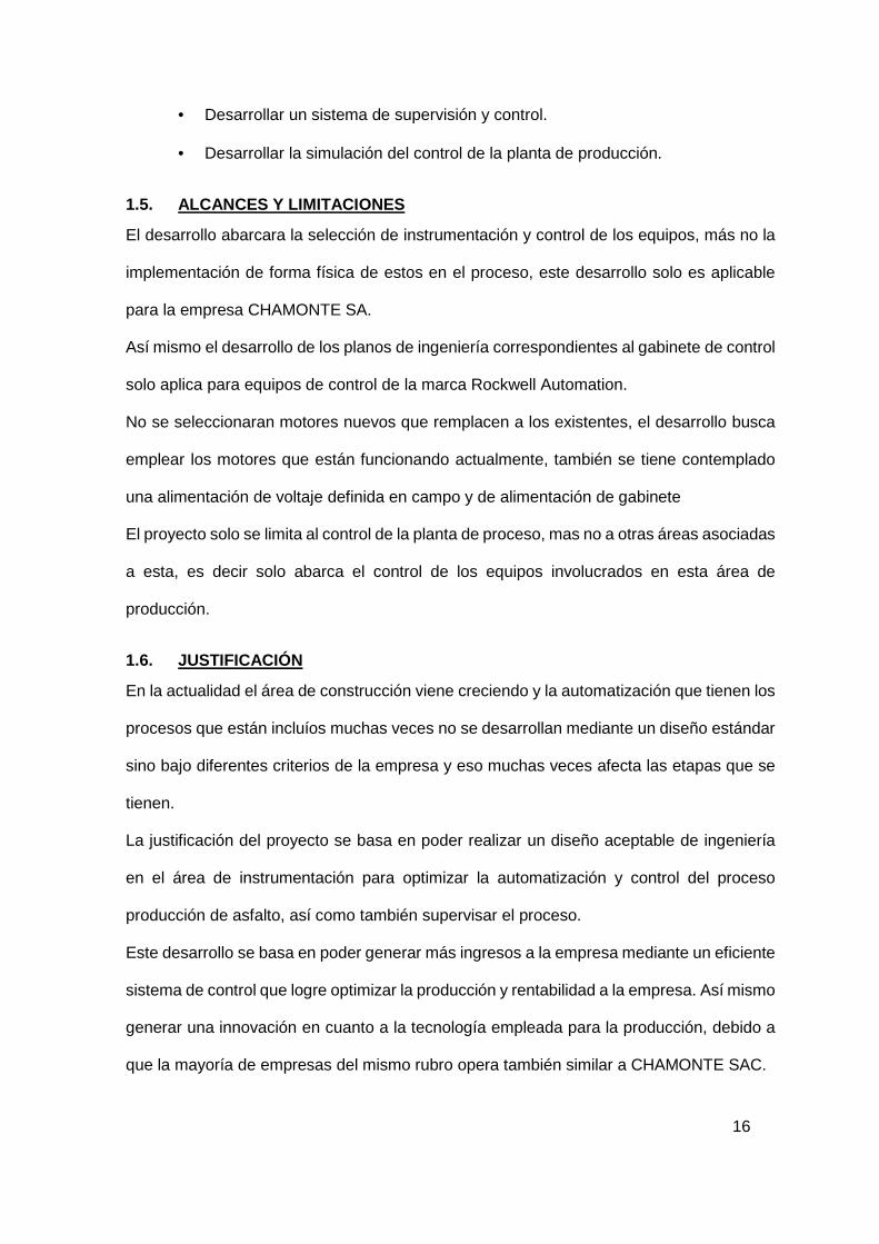
• Desarrollar un sistema de supervisión y control.
• Desarrollar la simulación del control de la planta de producción.
1.5. ALCANCES Y LIMITACIONES
El desarrollo abarcara la selección de instrumentación y control de los equipos, más no la
implementación de forma física de estos en el proceso, este desarrollo solo es aplicable
para la empresa CHAMONTE SA.
Así mismo el desarrollo de los planos de ingeniería correspondientes al gabinete de control
solo aplica para equipos de control de la marca Rockwell Automation.
No se seleccionaran motores nuevos que remplacen a los existentes, el desarrollo busca
emplear los motores que están funcionando actualmente, también se tiene contemplado
una alimentación de voltaje definida en campo y de alimentación de gabinete
El proyecto solo se limita al control de la planta de proceso, mas no a otras áreas asociadas
a esta, es decir solo abarca el control de los equipos involucrados en esta área de
producción.
1.6. JUSTIFICACIÓN
En la actualidad el área de construcción viene creciendo y la automatización que tienen los
procesos que están incluíos muchas veces no se desarrollan mediante un diseño estándar
sino bajo diferentes criterios de la empresa y eso muchas veces afecta las etapas que se
tienen.
La justificación del proyecto se basa en poder realizar un diseño aceptable de ingeniería
en el área de instrumentación para optimizar la automatización y control del proceso
producción de asfalto, así como también supervisar el proceso.
Este desarrollo se basa en poder generar más ingresos a la empresa mediante un eficiente
sistema de control que logre optimizar la producción y rentabilidad a la empresa. Así mismo
generar una innovación en cuanto a la tecnología empleada para la producción, debido a
que la mayoría de empresas del mismo rubro opera también similar a CHAMONTE SAC.

17
1.7. ESTADO DEL ARTE
En la actualidad el Perú ha impulsado políticas que favorecen a la construcción de las obras
viales a lo largo y ancho del territorio, sin embargo existe la necesidad de mejorar los
sistemas de producción de mezcla asfáltica debido a que son muy pocas empresas que
trabajan con estándares definidos en los procesos involucrados.
Es por eso que “la automatización es la sustitución de la acción humana. Un sistema
automático supone siempre la existencia de una fuente de energía para poder mover los
mecanismos independientes o no entre sí, que hacen parte del mismo sistema de
automatización, de unas piezas de mando, las cuales ordenan el ciclo que debe realizar el
sistema y otras partes de trabajos que lo ejecutan. Las técnicas de automatización y según
el automatismo empleado, existe automatización mecánica, neumática, hidráulica, eléctrica
y electrónica. Sin embargo, existe la combinación entre ellas y en la práctica es lo más
habitual.” (Alfonso Lopez Cespedez, 2007)
Por otro lado “el sistema de control es el corazón de las plantas de asfalto modernas, tan
fundamental que a la fecha es obligatorio tenerlo en casi todos los países del mundo, pues
asegura las características de la mezcla y minimiza la incidencia del proceso en el medio
ambiente, a la vez que proporciona sensibles economías para el propietario. Un SCADA
maneja desde un computador central toda la operación, tomando lecturas de las variables
críticas y registrándolas, accionando los dispositivos de control y reportando los eventos
presentados.” (Internacional SA, 2015)
Existen también diversos métodos de control para el proceso de producción de asfalto,
como el que se desarrolló para la empresa Asfalto de Eg3 en Argentina. Un control basado
en lógica difusa, implementado en el sistema supervisor, para esto se necesitó analizar,
controlar, ofrecer seguridad con los tiempos de actualización de datos y resguardar al
sistema por posibles caídas de la PC. (Hernández)

18
CAPITULO 2
MARCO TEÓRICO
En este capítulo se dará a conocer los conceptos básicos del proceso de producción de
asfalto, así como también se hará referencia de los estándares usados para el desarrollo
de este proyecto. Se desarrollara los conceptos de automatización, control y comunicación
necesarios para un buen entendimiento y desarrollo del sistema de control.
2.1. ASFALTO
El asfalto, es un material viscoso, pegajoso y de color negro. Se utiliza mezclado con arena
o gravilla para pavimentar caminos y como revestimiento impermeabilizante de muros y
tejados. Las mezclas asfálticas son usadas como aglomerante para la construcción
de carreteras, autovías o autopistas. Está presente en el petróleo crudo y compuesto casi
por completo de betún bitumen. El asfalto es una sustancia que constituye la fracción más
pesada del petróleo crudo. (Wikipedia, 2012)
2.2. DIAGRAMA DE FLUJO DEL PROCESO
El siguiente diagrama de flujo es representa en general la operación de las plantas de
producción de asfalto. En el cual se indicaran los pasos que se siguen para realizar la
producción de la planta de asfalto.

19
Figura 2. Diagrama de flujo del proceso2
2 Fuente : Desarrollo propio
Calentamiento
Asfalto PEN 60-70
Transporte hacia
mezclador
Tolvas de áridos
Fajas transportadoras
de áridos
Secador de áridos de
forma rotatoria
Zaranda
Mezcladora de
materiales áridos y
asfalto Pen 60-70
Almacenamiento de asfalto
Procesamiento de áridos Procesamiento
de mezclado y elaboración
20
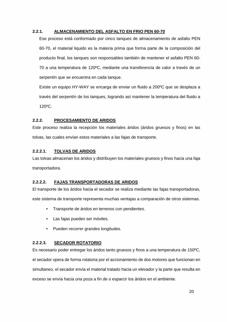
2.2.1. ALMACENAMIENTO DEL ASFALTO EN FRIO PEN 60-70
Ese proceso está conformado por cinco tanques de almacenamiento de asfalto PEN
60-70, el material liquido es la materia prima que forma parte de la composición del
producto final, los tanques son responsables también de mantener el asfalto PEN 60-
70 a una temperatura de 120ºC, mediante una transferencia de calor a través de un
serpentín que se encuentra en cada tanque.
Existe un equipo HY-WAY se encarga de enviar un fluido a 200ºC que se desplaza a
través del serpentín de los tanques, logrando así mantener la temperatura del fluido a
120ºC.
2.2.2. PROCESAMIENTO DE ARIDOS
Este proceso realiza la recepción los materiales áridos (áridos gruesos y finos) en las
tolvas, las cuales envían estos materiales a las fajas de transporte.
2.2.2.1. TOLVAS DE ARIDOS
Las tolvas almacenan los áridos y distribuyen los materiales gruesos y finos hacia una faja
transportadora.
2.2.2.2. FAJAS TRANSPORTADORAS DE ARIDOS
El transporte de los áridos hacia el secador se realiza mediante las fajas transportadoras,
este sistema de transporte representa muchas ventajas a comparación de otros sistemas.
• Transporte de áridos en terrenos con pendientes.
• Las fajas pueden ser móviles.
• Pueden recorrer grandes longitudes.
2.2.2.3. SECADOR ROTATORIO
Es necesario poder entregar los áridos tanto gruesos y finos a una temperatura de 150ºC,
el secador opera de forma rotatoria por el accionamiento de dos motores que funcionan en
simultaneo, el secador envía el material tratado hacia un elevador y la parte que resulta en
exceso se envía hacia una poza a fin de o esparcir los áridos en el ambiente.

21
2.2.2.4. ZARANDA
El elevador lleva los áridos hacia la parte más alta de la planta, es en la zaranda donde se
realiza la selección por movimientos vibratorios, esta distribución envía los áridos hacia los
compartimientos de material grueso y fino.
2.2.3. PROCESO DE MEZCLADO Y ELABORACION
Este proceso final se encarga de unir los materiales áridos y el fluido de asfalto. Ambos
materiales están almacenados en las compuertas del mezclador, estas compuertas
descargan material al sistema rotatorio de mezclado. El tiempo de apertura de compuertas
está relacionado a las recetas de producción.
El material resultante del proceso de mezclado es la mezcla asfáltica lista para su utilización
en la construcción de carreteras, el mismo que es llevado y almacenado en camiones de
transporte.
2.3. AUTOMATIZACION INDUSTRIAL
La Real Academia de las Ciencias Físicas y Exactas define la automática como el conjunto
de métodos y procedimientos para la substitución del operario en tareas físicas y mentales
previamente programadas. De esta definición original se desprende la definición de la
automatización como la aplicación de la automática al control de procesos industriales. Por
proceso, se entiende aquella parte del sistema en que, a partir de la entrada de material,
energía e información, se genera una transformación sujeta a perturbaciones del entorno,
que da lugar a la salida de material en forma de producto. (Pere Ponsa, 2007)
2.3.1. NIVELES DE AUTOMATIZACION INDUSTRIAL
Los niveles de control de un proceso están basados principalmente en la pirámide de la
automatización, la cual indica la forma de organizar las funciones de la automatización.

22
Figura 3. Pirámide de automatización3
• Dirección Corporativa: lo integra la ERP por sus siglas en ingles de Enterprise
Resource Planning (Planificación de Recursos Empresariales). En este nivel están
integradas distintas tareas como la de operación, producción y negocios de una
empresa a través de la automatización. Pronostica la oferta y demanda de los
productos mediante los datos obtenidos de los niveles inferiores, gracias a esto se
puede brindar buenos productos, reducir costos, reducir precios y brindar
soluciones prácticas.
• Nivel de Gestión: Integrada por la MES (Manufacturing Execution System). Este
nivel se encarga de la planeación y el control de la producción en tiempo real, para
así optimizar el proceso.
• Control de Procesos: Conformada por el SCADA (Supervisory Control and Data
Acquisition)-Supervisión, control y adquisición de datos, establece la interfaz
Hombre-Máquina que permite al usuario la comunicación con dispositivo de campo
para así poder supervisar y controlar de las variables de proceso de forma remota.
• Nivel de control Celula: PLC (Programming Logic Controller)- Controlador Lógico
Programable en este nivel el sistema de control adquiere los datos de las variables
3 Fuente “Comunicaciones Industriales”, Dep. Ing. de Automática – Universidad Carlos III de Madrid
23
de proceso por medio de sensores o transmisores, el cual realiza los cálculos y
lleva a cabo la acción de control.
• Nivel de Campo: Este nivel se encuentran los sensores y actuadores, los cuales
están ubicados en campo y mandan las señales a niveles superiores.
2.3.2. METODOS DE CONTROL DE UN PROCESO
El control automático ha desempeñado un papel vital en el avance de la ingeniería y la
ciencia. Se ha convertido en una parte importante e integral en los sistemas de vehículos
espaciales, en los sistemas robóticos, en los procesos modernos de fabricación y en
cualquier operación industrial que requiera el control de temperatura, presión, humedad,
flujo, etc.
En este capítulo se explicara los diversos métodos que se emplean para realizar el control
automático de un proceso, es decir los diversos tipos de control que puedo aplicar a mis
lazos de control. (Ogata, 2010)
2.3.2.1. CONTROL PID
El control Proporcional-Integral-Derivativo PID es el que más se utilizan en la industria.
El sistema de control del PID viene a ser dado por 3 parámetros: el proporcional, el
integrativo y el derivativo, estos parámetros se ajustan con la finalidad de hacer un control
aceptable y que cumpla con las expectativas que se tienen para el proceso como: el tiempo
de respuesta, la estabilidad, tiempo de establecimiento. No siempre los 3 parámetros van
a tener un valor, se puede dar el caso de que alguno de estos sea 0.

24
Figura 4. Diagrama de un controlador PID4
La suma de estas tres acciones es usada para ajustar al proceso por medio de un elemento
de control como la posición de una válvula de control o la potencia suministrada a un
calentador.
Cuando no se tiene conocimiento del proceso, históricamente se ha considerado que el
controlador PID es el controlador más adecuado. Ajustando estas tres variables en el
algoritmo de control del PID, el controlador puede proveer una acción de control diseñado
para los requerimientos del proceso en específico. La respuesta del controlador puede
describirse en términos de la respuesta del control ante un error, el grado el cual el
controlador sobrepasa el punto de ajuste, y el grado de oscilación del sistema. El uso del
PID para control no garantiza control óptimo del sistema o la estabilidad del mismo.
Cuando el modelo matemático de la planta no se conoce y, por lo tanto, no se pueden
emplear métodos de diseño analíticos, es cuando los controles PID resultan más útiles. En
el campo de los sistemas para control de procesos, es un hecho bien conocido que los
4 Fuente Libro “Ingeniería de Control Moderna”, Ogata K.
25
2.3.2.2. CONTROL DIFUSO
La teoría difusa y los sistemas difusos han tenido un importante progreso en muchas
aplicaciones desde sus comienzos. En el campo de la ingeniería, numerosas aplicaciones
industriales han alcanzado buenos resultados.
La palabra “difusa” o “difusa” que en inglés es “fuzzy”, se puede interpretar como “borroso,
indistinto, impreciso, confuso, vago”, pero se debe desatender esta definición y ver la
palabra “difusa” como un adjetivo. Esencialmente, lo que se quiere enfatizar es que aun
cuando los fenómenos que caracterizan a la teoría difusa o a los sistemas difusos pueden
ser difusos, la propia teoría es precisa.
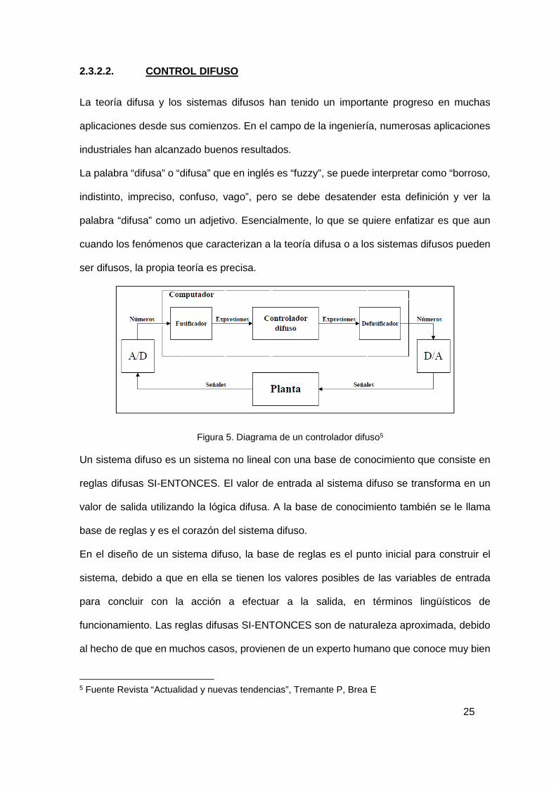
Figura 5. Diagrama de un controlador difuso5
Un sistema difuso es un sistema no lineal con una base de conocimiento que consiste en
reglas difusas SI-ENTONCES. El valor de entrada al sistema difuso se transforma en un
valor de salida utilizando la lógica difusa. A la base de conocimiento también se le llama
base de reglas y es el corazón del sistema difuso.
En el diseño de un sistema difuso, la base de reglas es el punto inicial para construir el
sistema, debido a que en ella se tienen los valores posibles de las variables de entrada
para concluir con la acción a efectuar a la salida, en términos lingüísticos de
funcionamiento. Las reglas difusas SI-ENTONCES son de naturaleza aproximada, debido
al hecho de que en muchos casos, provienen de un experto humano que conoce muy bien
5 Fuente Revista “Actualidad y nuevas tendencias”, Tremante P, Brea E

26
el proceso al cual se le implementará el sistema difuso. Por tanto, la colección de las reglas
difusas es un razonamiento aproximado. Un sistema difuso basado en reglas SI-
ENTONCES, difiere de un sistema experto que también está formado por una serie de
reglas SI-ENTONCES. En las reglas del sistema difuso el antecedente y la consecuencia
están formados por conjuntos difusos, mientras que en las reglas del sistema experto no.
(Tremante P, 2007)
2.4. COMUNICACIÓN INDUSTRIAL
En la actualidad la comunicación industrial en un proceso de automatizado son importantes
debido a que se tienen grandes ventajas en lo que respecta a control o a instrumentación.
Una de las ventajas es que se puede hacer monitoreo de procesos aun estando lejos del
lugar, se puede ahorrar cableado para instrumentos ya que se pueden enviar varias
señales por buses de comunicación y también se puede optimizar mejor el proceso.
2.4.1. PROTOCOLOS DE COMUNICACIÓN
En principio un protocolo de comunicación es un conjunto de reglas que permiten la
transferencia e intercambio de datos entre los distintos dispositivos que conforman una red.
(Asociación de la industria electrica y electronica Chile, 2013)
Figura 6. Coexistencia de múltiples redes6
6 Fuente Revista “Actualidad y nuevas tendencias”, Tremante P, Brea E

27
A continuación se explica los principales protocolos de comunicación que se emplean en
las industrias.7
• FOUNDATION FIELDBUS
Su objetivo es sustituir el habitual bucle de corriente 4-20 mA de la conexión punto a punto
entre los elementos y el equipo de control.
• HART
El protocolo HART (High way-AddressableRemote-Transducer) agrupa la señal digital
sobre la analógica de 4 a 20mA. La señal digital usa dos frecuencias individuales de 1200
y 2200 Hz, que representan los dígitos 1 y 0 respectivamente y que en conjunto forman
una onda sinusoidal que se superpone al lazo de corriente de 4-20 mA.
• MODBUS
Modbus es un protocolo de transmisión para sistemas de control y supervisión de procesos
(SCADA) con control centralizado, puede comunicarse con una o varias Estaciones
Remotas (RTU) con la finalidad de obtener datos de campo para la supervisión y control
de un proceso. La Interfaces de Capa Física puede estar configurada en: RS-232, RS-422,
RS-485.
• DEVICENET
Red de bajo nivel adecuada para conectar dispositivos simples como sensores
fotoeléctricos, sensores magnéticos, pulsadores, etc. y dispositivos de alto nivel (PLC,
controladores, computadores, HMI, entre otros). Provee información adicional sobre el
estado de la red, cuyos datos serán desplegados en la interfaz del usuario.
• TCP/IP
El protocolo TCP/IP permite conectar y comunicar cualquier tipo de computadora sin
importar su marca o sistema operativo, es muy usado en la actualidad debido a que existe
una red mundial que es el internet la que usa este protocolo.
7 Fuente “Comunicaciones Industriales”, Dep. Ing. de Automática – Universidad Carlos III de Madrid

28
2.5. SISTEMAS SCADA
El nombre de SCADA viene de las siglas Supervisión, Control y Adquisición de Datos, es
un sistema que se usa para monitorear y controlar en tiempo real los estados de un
proceso. Los trabajos que se dedica una aplicación de supervisión son:
• Monitoreo de Alarmas.
• Códigos de animación.
• Códigos de seguridad.
• Códigos de supervisión.
• Datos históricos almacenados.
• Integración con otras aplicaciones y base de datos.
• Detección de eventos.
• Integración de dispositivos.
Figura 7. Scada plataforma InTouch Wonderware8
8 Fuente manual “InTouch10.1-Part1RevB_EntireManual”, Wonderware
29
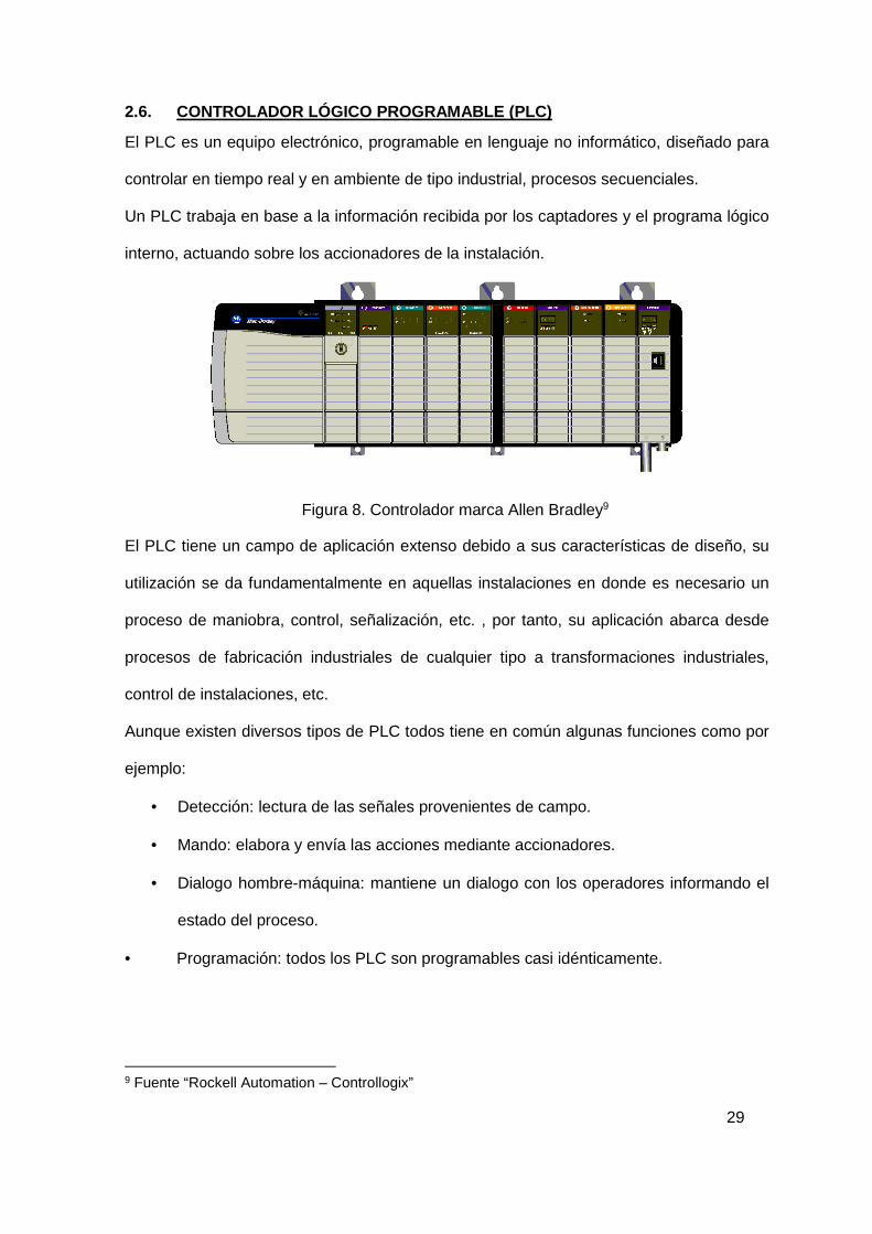
2.6. CONTROLADOR LÓGICO PROGRAMABLE (PLC)
El PLC es un equipo electrónico, programable en lenguaje no informático, diseñado para
controlar en tiempo real y en ambiente de tipo industrial, procesos secuenciales.
Un PLC trabaja en base a la información recibida por los captadores y el programa lógico
interno, actuando sobre los accionadores de la instalación.
Figura 8. Controlador marca Allen Bradley9
El PLC tiene un campo de aplicación extenso debido a sus características de diseño, su
utilización se da fundamentalmente en aquellas instalaciones en donde es necesario un
proceso de maniobra, control, señalización, etc. , por tanto, su aplicación abarca desde
procesos de fabricación industriales de cualquier tipo a transformaciones industriales,
control de instalaciones, etc.
Aunque existen diversos tipos de PLC todos tiene en común algunas funciones como por
ejemplo:
• Detección: lectura de las señales provenientes de campo.
• Mando: elabora y envía las acciones mediante accionadores.
• Dialogo hombre-máquina: mantiene un dialogo con los operadores informando el
estado del proceso.
• Programación: todos los PLC son programables casi idénticamente.
9 Fuente “Rockell Automation – Controllogix”
30
CAPÍTULO 3
DESARROLLO DE LA SOLUCIÓN En el siguiente capítulo se explicará los criterios de diseño que se han tenido en cuenta
para el desarrollo del proyecto, así como también el desarrollo de la ingeniería para el
control del proceso.
3.1. INSPECCIÓN TECNICA DE LA PLANTA CHAMONTE
Antes de proponer un diseño de control fue necesario realizar una visita técnica a la
empresa CHAMONTE S.A., se realizó una inspección tanto de la parte eléctrica como
mecánica.
3.1.1. INSPECCIÓN ELÉCTRICA
3.1.1.1. ZONA DE TOLVAS
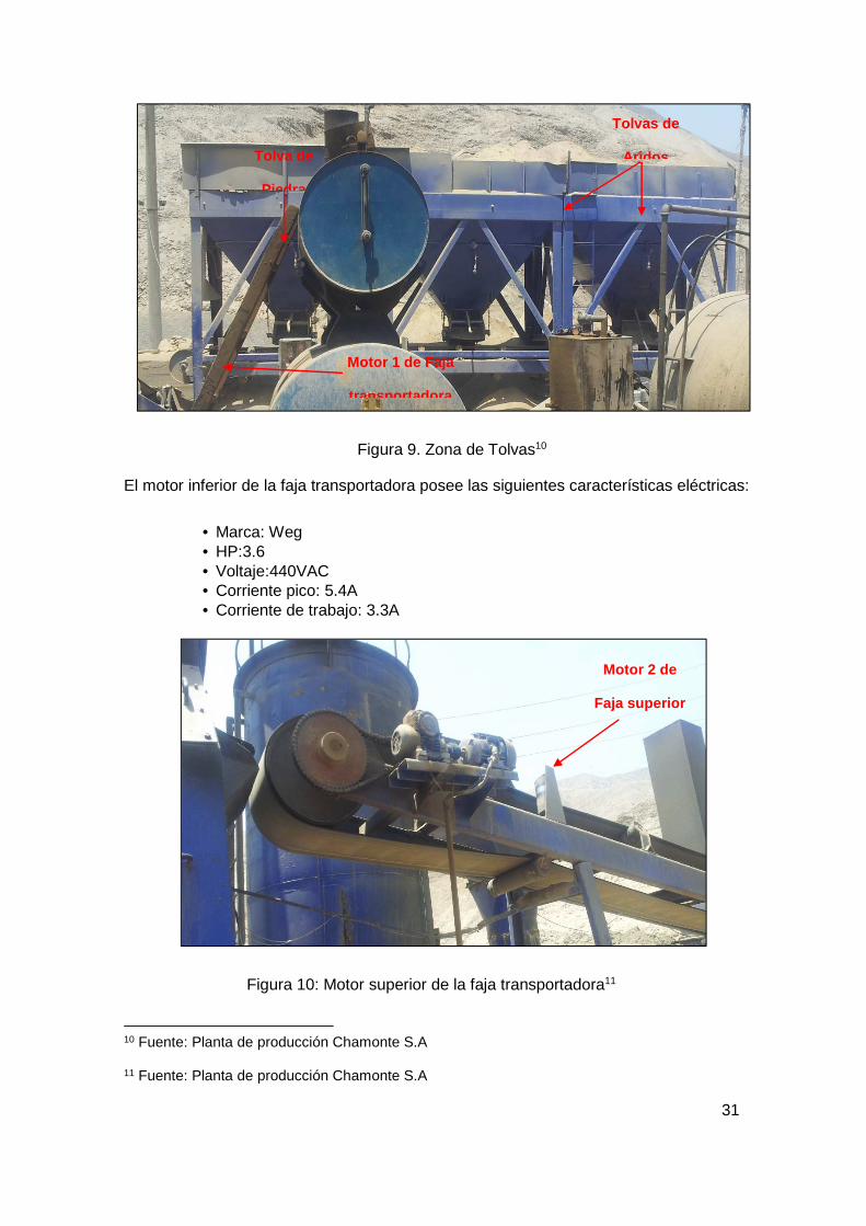
La zona de tolvas está ubicada en la parte inferior de la planta, la cual recepcionan los
áridos y solidos que van hacia la faja transportadora, la cual posee dos motores en la faja
transportadora y tres motores vibratorios ubicada cada uno en la parte posterior de la
compuerta de la tolva.
31
Figura 9. Zona de Tolvas10
El motor inferior de la faja transportadora posee las siguientes características eléctricas:
• Marca: Weg • HP:3.6 • Voltaje:440VAC • Corriente pico: 5.4A • Corriente de trabajo: 3.3A
Figura 10: Motor superior de la faja transportadora11
10 Fuente: Planta de producción Chamonte S.A
11 Fuente: Planta de producción Chamonte S.A
Tolvas de
Aridos Tolva de
Piedra
Motor 1 de Faja
transportadora
Motor 2 de
Faja superior
32
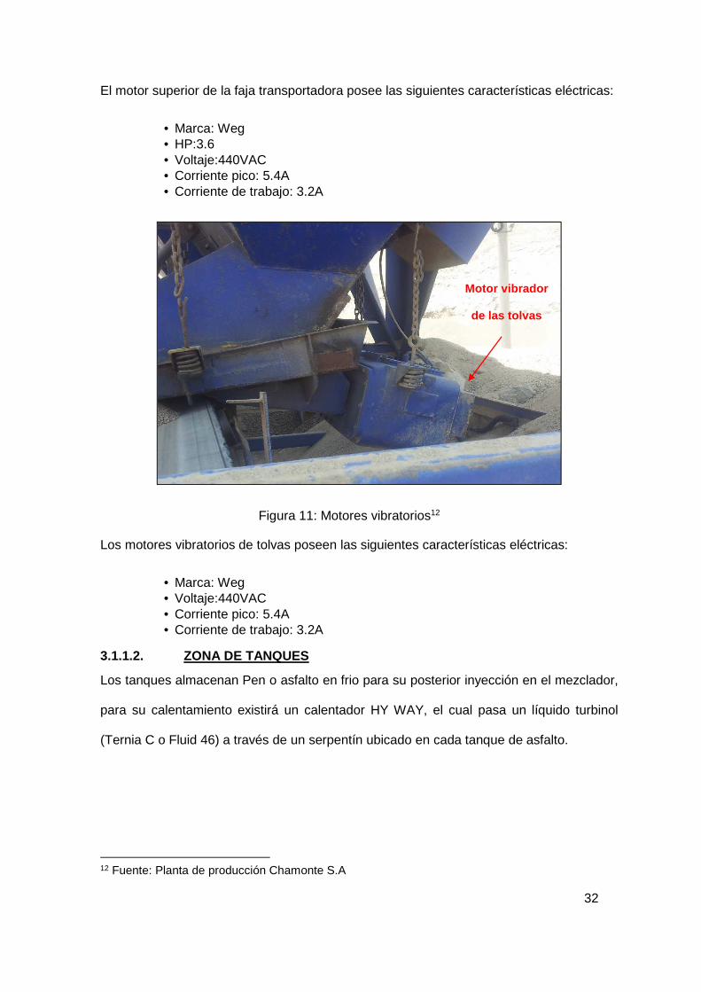
El motor superior de la faja transportadora posee las siguientes características eléctricas:
• Marca: Weg • HP:3.6 • Voltaje:440VAC • Corriente pico: 5.4A • Corriente de trabajo: 3.2A
Figura 11: Motores vibratorios12
Los motores vibratorios de tolvas poseen las siguientes características eléctricas:
• Marca: Weg • Voltaje:440VAC • Corriente pico: 5.4A • Corriente de trabajo: 3.2A
3.1.1.2. ZONA DE TANQUES
Los tanques almacenan Pen o asfalto en frio para su posterior inyección en el mezclador,
para su calentamiento existirá un calentador HY WAY, el cual pasa un líquido turbinol
(Ternia C o Fluid 46) a través de un serpentín ubicado en cada tanque de asfalto.
12 Fuente: Planta de producción Chamonte S.A
Motor vibrador
de las tolvas

33
Figura 12: Controlador del HY WAY13
En el tablero del HY WAY, ubicado al costado del calentador, se ubica un micro controlador
que básicamente controla la temperatura del fluido (200 ºC) este tablero tiene propia
alimentación dada desde el tablero principal de alimentación, es decir es independiente.
Figura 13: Controlador del HY WAY14
13 Fuente: Planta de producción Chamonte S.A
14 Fuente: Planta de producción Chamonte S.A
Bomba del HY WAY
34
El motor de la bomba HY WAY posee las siguientes características:
• Marca: Weg • HP: 7.5 • Voltaje:440VAC • Corriente pico: 9.6A • Corriente de trabajo: 6.5A
En la zona de tanques existe una bomba que lleva el asfalto hacia el mezclador, la cual
tiene las siguientes características:
• Marca: Weg • HP: 10HP • Voltaje:440VAC • Corriente pico: 13.5A • Corriente de trabajo: 12.8A
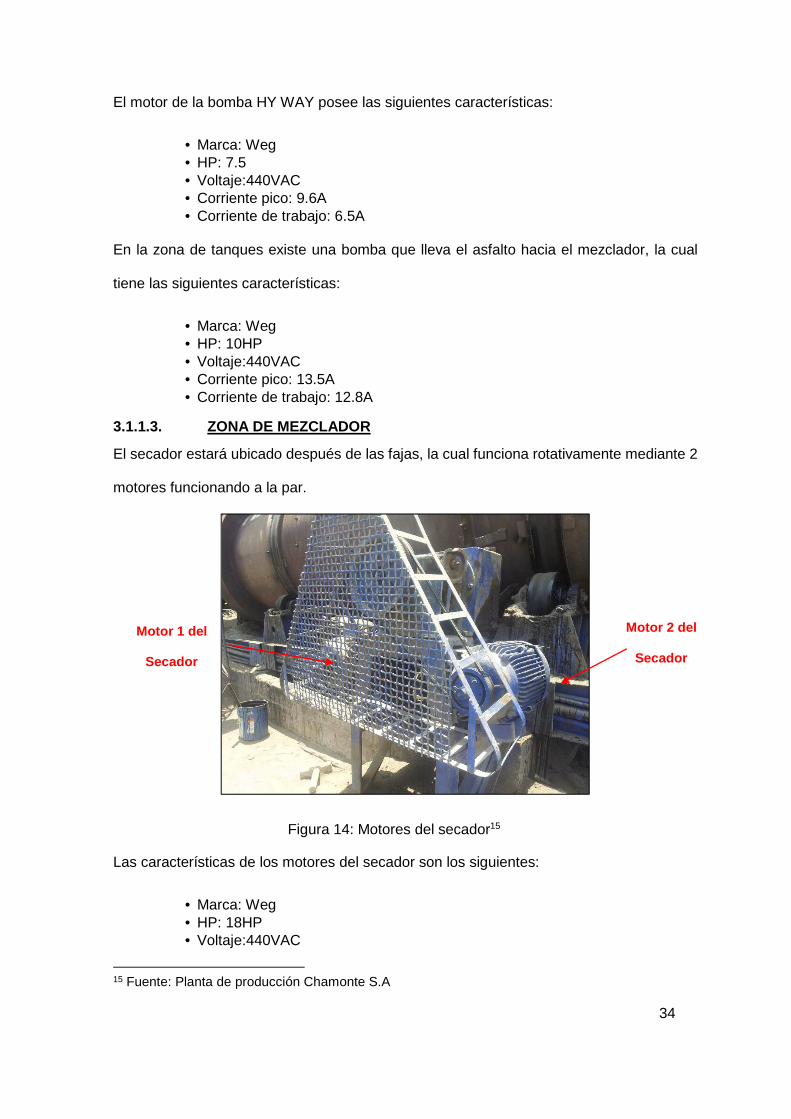
3.1.1.3. ZONA DE MEZCLADOR
El secador estará ubicado después de las fajas, la cual funciona rotativamente mediante 2
motores funcionando a la par.
Figura 14: Motores del secador15
Las características de los motores del secador son los siguientes:
• Marca: Weg • HP: 18HP • Voltaje:440VAC
15 Fuente: Planta de producción Chamonte S.A
Motor 2 del
Secador
Motor 1 del
Secador

35
• Corriente pico: 24A • Corriente de trabajo: 15A
En esta zona también se ubica el quemador, el cual funciona como un mechero para elevar
la temperatura de los materiales áridos, los datos del quemador del HY WAY son los
siguientes:
• Marca: Weg • HP: 0.5 • Voltaje:115VAC • Corriente pico: 6.4A • Corriente de trabajo: 3.8A
Figura 15: Quemador del HY WAY16
16 Fuente: Planta de producción Chamonte S.A
Quemador en
funcionamiento
36
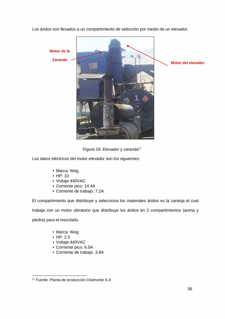
Los áridos son llevados a un compartimiento de selección por medio de un elevador.
Figura 16: Elevador y zaranda17
Los datos eléctricos del motor elevador son los siguientes:
• Marca: Weg • HP: 10 • Voltaje:440VAC • Corriente pico: 14.4A • Corriente de trabajo: 7.2A
El compartimiento que distribuye y selecciona los materiales áridos es la zaranja el cual
trabaja con un motor vibratorio que distribuye los áridos en 2 compartimientos (arena y
piedra) para el mezclado.
• Marca: Weg • HP: 2.5 • Voltaje:440VAC • Corriente pico: 6.5A • Corriente de trabajo: 3.8A
17 Fuente: Planta de producción Chamonte S.A
Motor del elevador
Motor de la
Zaranda

37
Los áridos son mezclados en una mezcladora que cuenta con un motor relacionado con
dos engranajes que funcionan a la par.
Figura 17: Motor del mezclador18
Los datos del motor del mezclador son los siguientes:
• Marca: Weg • HP: 50 • Voltaje:440VAC • Corriente pico: 59.5A • Corriente de trabajo: 40.45A
3.1.1.4. LÍNEA NEUMÁTICA – BOMBA DE AIRE
En una caseta está ubicada la bomba de aire de la línea neumática para la inyección de
los áridos mediante cilindros neumáticos.
Figura 18: Bomba de aire19
18 Fuente: Planta de producción Chamonte S.A
19 Fuente: Planta de producción Chamonte S.A
Motor del mezclador

38
Los datos de la bomba del compresor:
• Marca: Weg 8 Bar • HP: 10 • Voltaje:440VAC • Corriente pico: 11A • Corriente de trabajo: 8A
3.1.1.5. ZONA DEL TABLERO GENERAL ELÉCTRICO DE LOS MOTORES
Los motores arrancan de manera simultánea desde un tablero general de forma manual,
este tablero está ubicado en la parte del proceso de mezcla, actualmente se encuentra en
malas condiciones, lo cual puede significar un peligro para el operador.
Figura 19: Tablero eléctrico de los motores vista frontal 20
20 Fuente: Planta de producción Chamonte S.A
39
3.1.2. INSPECCION MECANICA
3.1.2.1. ZONA DE TANQUES
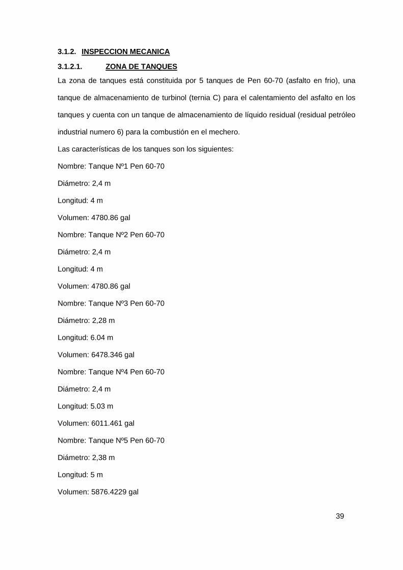
La zona de tanques está constituida por 5 tanques de Pen 60-70 (asfalto en frio), una
tanque de almacenamiento de turbinol (ternia C) para el calentamiento del asfalto en los
tanques y cuenta con un tanque de almacenamiento de líquido residual (residual petróleo
industrial numero 6) para la combustión en el mechero.
Las características de los tanques son los siguientes:
Nombre: Tanque Nº1 Pen 60-70
Diámetro: 2,4 m
Longitud: 4 m
Volumen: 4780.86 gal
Nombre: Tanque Nº2 Pen 60-70
Diámetro: 2,4 m
Longitud: 4 m
Volumen: 4780.86 gal
Nombre: Tanque Nº3 Pen 60-70
Diámetro: 2,28 m
Longitud: 6.04 m
Volumen: 6478.346 gal
Nombre: Tanque Nº4 Pen 60-70
Diámetro: 2,4 m
Longitud: 5.03 m
Volumen: 6011.461 gal
Nombre: Tanque Nº5 Pen 60-70
Diámetro: 2,38 m
Longitud: 5 m
Volumen: 5876.4229 gal

40
Nombre: Tanque bunquer
Diámetro: 1,27m
Longitud: 4 m
Volumen: 5327.704 gal
Figura 20: Tanques de almacenamiento de Pen 60-70 21
Los datos relevados al realizar la inspección en campo de las tuberías correspondientes a
las líneas de fluido correspondientes al proceso fueron los siguientes:
• Línea de asfalto Pen 60-70 ᶲ4”. • Línea de inyección al mechero (bunker) 60-70 ᶲ2 1/2”. • Línea de calentador de tanques ᶲ1” (tubería enchaquetada).
21 Fuente: Planta de producción Chamonte S.A

41
Figura 21: Línea del tanque de almacenamiento22
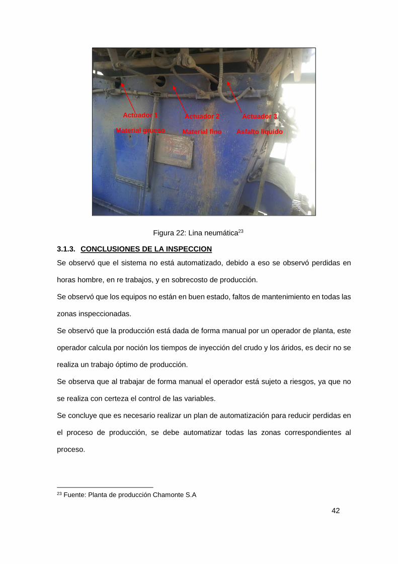
3.1.2.2. ZONA DE MEZCLADOR
En la zona de mezclador se realiza el mezclado de los áridos (material grueso y fino) con
el líquido asfalto caliente a 120ºC.
El proceso de mezclado se lleva a cabo por tres actuadores, cilindros neumáticos que
accionan cada una de las compuertas que almacenan los materiales a mezclar. La línea
neumática es de 180Psi y la forma de activación es manual por el operador.
22 Fuente: Planta de producción Chamonte S.A
Linea de calentador
de tanques Linea de Asfalto
60-70
Salida de línea de
calentador
42
Figura 22: Lina neumática23
3.1.3. CONCLUSIONES DE LA INSPECCION
Se observó que el sistema no está automatizado, debido a eso se observó perdidas en
horas hombre, en re trabajos, y en sobrecosto de producción.
Se observó que los equipos no están en buen estado, faltos de mantenimiento en todas las
zonas inspeccionadas.
Se observó que la producción está dada de forma manual por un operador de planta, este
operador calcula por noción los tiempos de inyección del crudo y los áridos, es decir no se
realiza un trabajo óptimo de producción.
Se observa que al trabajar de forma manual el operador está sujeto a riesgos, ya que no
se realiza con certeza el control de las variables.
Se concluye que es necesario realizar un plan de automatización para reducir perdidas en
el proceso de producción, se debe automatizar todas las zonas correspondientes al
proceso.
23 Fuente: Planta de producción Chamonte S.A
Actuador 1
Material grueso
Actuador 2
Material fino
Actuador 3
Asfalto liquido

43
3.2. ARQUITECTURA DE CONTROL
Se plantea la siguiente arquitectura del sistema de control:
Para el diseño del sistema de control se ha empleado una arquitectura jerárquica, donde
el nivel más alto de la automatización será el SCADA compuesto por servidores y
estaciones de operación e ingeniería, estos servidores recibirán y enviarán datos a un PLC
Controllogix a través de una red de control con protocolo Ethernet TCP/IP, estos estarán
conectados entre sí por medio de un Switch administrable. Como último nivel jerárquico
tendremos la instrumentación de campo que será cableada hacia el PLC por medio de
cableado duro.
La instrumentación se ubicará en campo, los equipos de control y comunicación tales como
el PLC y switch se encontrarán dentro de un gabinete de control; el servidor y monitor se
ubicarán en una sala de operadores.
A continuación se muestra la representación gráfica de la arquitectura de control en
resumen.
Figura 23. Resumen de la arquitectura de control24
24 Fuente: Desarrollo propio

44
El grafico mostrado es una ilustración del resumen de la arquitectura de control, el plano
de arquitectura de control se encuentra en el Anexo 1: Plano de arquitectura de control.
3.3. LISTA DE INSTRUMENTOS
En esta lista se puede observar todos los instrumentos involucrados en el proceso, también
se están considerando los sensores de temperatura, nivel de los tanques de
almacenamiento de asfalto.
Se ha elaborado un plano de ubicación del proceso, en donde se describe las áreas
involucradas, el cual está en el Anexo 2: Plot plan.
A continuación se muestran las características más resaltantes de los instrumentos usados
en el proceso, para mayor detalle revisar el Anexo 3: Lista de señales e instrumentos.
Tag Equipo
Descripción Ubicación Tipo Señal RTU Chasis Modulo Slot Canal Rango Unidad
LT-0001
Transmisor de nivel del tanque TK-
001
Zona de tanques
AI 4-20 m
A 1000 1
1756-IF16
2 0 0 - 10 m.
TT-0001
Transmisor de
temperatura del tanque
TK-001
Zona de tanques
AI 4-20 m A
1000 1 1756-IF16
2 1 0 - 150
ºC
ZI-0001
Indicador de posicion de la valvula 1000-CV-
0001
Zona de tanques
AI 2-10 VDC
1000 1 1756-IF16
2 2 0 - 100
%
LT-0002
Transmisor de nivel del tanque TK-
002
Zona de tanques
AI 4-20 m
A 1000 1
1756-IF16
2 3 0 - 10 m.
TT-0002
Transmisor de
temperatura del tanque
TK-002
Zona de tanques
AI 4-20 m A
1000 1 1756-IF16
2 4 0 - 150
ºC
ZI-0002
Indicador de posicion de la valvula 1000-CV-
0002
Zona de tanques
AI 2-10 VDC
1000 1 1756-IF16
2 5 0 - 100
%
LT-0003
Transmisor de nivel del tanque TK-
003
Zona de tanques
AI 4-20 m
A 1000 1
1756-IF16
2 6 0 - 10 m.

45
TT-0003
Transmisor de
temperatura del tanque
TK-003
Zona de tanques
AI 4-20 m A
1000 1 1756-IF16
2 7 0 - 150
ºC
ZI-0003
Indicador de posicion de la valvula 1000-CV-
0003
Zona de tanques
AI 2-10 VDC
1000 1 1756-IF16
2 8 0 - 100
%
LT-0004
Transmisor de nivel del tanque TK-
004
Zona de tanques
AI 4-20 m
A 1000 1
1756-IF16
2 9 0 - 10 m.
TT-0004
Transmisor de
temperatura del tanque
TK-004
Zona de tanques AI
4-20 m A 1000 1
1756-IF16 2 10
0 - 150 ºC
ZI-0004
Indicador de posicion de la valvula 1000-CV-
0004
Zona de tanques
AI 2-10 VDC
1000 1 1756-IF16
2 11 0 - 100
%
LT-0005
Transmisor de nivel del tanque TK-
005
Zona de tanques
AI 4-20 m
A 1000 1
1756-IF16
2 12 0 - 10 m.
TT-0005
Transmisor de
temperatura del tanque
TK-005
Zona de tanques
AI 4-20 m
A 1000 1
1756-IF16
2 13 0 - 150
ºC
ZI-0005
Indicador de posicion de la valvula 1000-CV-
0005
Zona de tanques
AI 2-10 VDC
1000 1 1756-IF16
2 14 0 - 100
%
CV-0001
Salida control de actuador de valvula 1000-CV-
0001
Zona de tanques
AO 2-
10VDC 1000 1
1756-OF8
3 0 0-100 %
CV-0002
Salida control de actuador de valvula 1000-CV-
0002
Zona de tanques
AO 2-
10VDC 1000 1
1756-OF8
3 1 0-100 %
CV-0003
Salida control de actuador de valvula 1000-CV-
0003
Zona de tanques
AO 2-
10VDC 1000 1
1756-OF8
3 2 0-100 %
CV-0004
Salida control de actuador de valvula 1000-CV-
0004
Zona de tanques
AO 2-
10VDC 1000 1
1756-OF8
3 3 0-100 %

46
CV-0005
Salida control de actuador de valvula 1000-CV-
0005
Zona de tanques
AO 2-10VDC
1000 1 1756-OF8
3 4 0-100 %
ZS-10001
Deteccion de puerta
abierta RTU-1000
Caseta de control
- - - 1 1756-IB32
5 0 - -
XS-10001 Conmutacion
Linea - Bateria
Caseta de control - - - 1
1756-IB32 5 1 - -
XS-10002 Ausencia de bateria
Caseta de control
- - - 1 1756-IB32
5 2 - -
XS-10003 Estado de
bateria Caseta de
control - - - 1
1756-IB32
5 3 - -
M-001
Salida activacion del
motor del HYWAY
Zona del mezclador
DO NA 1000 1 1756-OW16I
6 0 - -
M-002
Salida activacion del
motor del Bunker
Zona del mezclador
DO NA 1000 1 1756-OW16I
6 1 - -
M-003 Salida
activacion del motor faja 1
Zona del mezclador
DO NA 1000 1 1756-OW16I
6 2 - -
M-004
Salida activacion del
motor vibratorio 1
Zona del mezclador
DO NA 1000 1 1756-OW16I
6 3 - -
M-005
Salida activacion del
motor vibratorio 2
Zona del mezclador DO NA 1000 1
1756-OW16I 6 4 - -
M-006
Salida activacion del
motor vibratorio 3
Zona del mezclador
DO NA 1000 1 1756-OW16I
6 5 - -
M-007 Salida
activacion del motor faja 2
Zona del mezclador DO NA 1000 1
1756-OW16I 6 6 - -
M-008
Salida activacion del
motor secador 1
Zona del mezclador
DO NA 1000 1 1756-OW16I
6 7 - -
M-009
Salida activacion del
motor secador 2
Zona del mezclador DO NA 1000 1
1756-OW16I 6 8 - -
M-010
Salida activacion del
motor del elevador
Zona del mezclador
DO NA 1000 1 1756-OW16I
6 9 - -
M-011 Salida
activacion del motor
Zona del mezclador DO NA 1000 1
1756-OW16I 6 10 - -

47
succion de aridos
M-012
Salida activacion del motor de la
zaranda
Zona del mezclador
DO NA 1000 1 1756-OW16I
6 11 - -
M-013
Salida activacion del
motor del mezclador
Zona del mezclador
DO NA 1000 1 1756-OW16I
6 12 - -
P-001
Salida activacion de la bomba de
asfalto
Zona del mezclador
DO NA 1000 1 1756-OW16I
6 13 - -
P-002
Salida de activacion de la bomba de
aire
Zona del mezclador
DO NA 1000 1 1756-OW16I
6 14 - -
P-003
Salida de activacion de la bomba de
agua
Zona del mezclador
DO NA 1000 1 1756-OW16I
6 15 - -
XC-001
Salida activacion de electrovalvula
XC-001
Zona del mezclador
DO NA 1000 1 1756-OW16I
7 0 - -
XC-002
Salida activacion de electrovalvula
XC-002
Zona del mezclador
DO NA 1000 1 1756-OW16I
7 1 - -
XC-003
Salida activacion de electrovalvula
XC-003
Zona del mezclador
DO NA 1000 1 1756-OW16I
7 2 - -
XC-004
Salida activacion de electrovalvula
XC-004
Zona del mezclador
DO NA 1000 1 1756-OW16I
7 3 - -
Tabla 1: Lista de Instrumentos
3.4. SELECCIÓN DE INSTRUMENTACION
La selección del instrumento es una cosa importante en cualquier planta industrial para
medir la cantidad específica.
Los siguientes puntos han sido considerados como criterio de selección de los instrumentos
de medición:
• El primer punto que fue considerado en la selección del instrumento es el requisito
de las características del instrumento y sus especificaciones, resolución, exactitud
en la medida deseada, sensibilidad y rendimiento enérgico.
48
• El conocimiento sobre las condiciones del entorno de la zona donde está siendo
sometido el instrumento también fue importante. Porque algunos tipos de
instrumentos no debe utilizarse si el medio ambiente no es adecuado o pueden
requerir una protección específica.
• El instrumento también es seleccionado por su tipo de montaje hacia el proceso, es
decir conexión bridada, soldada, etc.
• Se tiene como base también los planos P&ID, los cuales especifican las
dimensiones de las tuberías en las cuales van montados los instrumentos indicados
en los planos desarrollados.
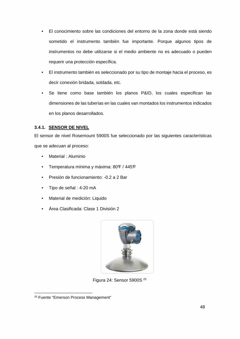
3.4.1. SENSOR DE NIVEL
El sensor de nivel Rosemount 5900S fue seleccionado por las siguientes características
que se adecuan al proceso:
• Material : Aluminio
• Temperatura mínima y máxima: 80°F / 445°F
• Presión de funcionamiento: -0.2 a 2 Bar
• Tipo de señal : 4-20 mA
• Material de medición: Liquido
• Área Clasificada: Clase 1 División 2
Figura 24: Sensor 5900S 25
25 Fuente “Emerson Process Management”

49
3.4.2. SENSOR DE TEMPERATURA
El sensor de temperatura Rosemount 224OSP083AFI70A1PST fue seleccionado por las siguientes características que se adecuan al proceso:
• Material : Aluminio
• Temperatura mínima y máxima: 40°F / 305°F
• Tipo de señal : 4-20 mA
• Material de medición: Liquido
• Intrínsecamente seguro
Figura 25: Sensor de temperatura Rosemount 26
3.4.3. VALVULA DE CONTROL
Se seleccionó la válvula de control de flujo Honeywell V5049A,B con conexión bridada al
proceso. Fue seleccionada por sus características de operación de control modulante en
líquidos de sistemas de calefacción o intercambiadores de calor.
• Presión nominal: PN16 ó PN25/40
• Característica: Igual Porcentaje
• Relación de Precisión: 30:1
• Conexiones: Bridas según ISO 7005-2
26 Fuente “Emerson Process Management”

50
• Material: Hierro fundido (GG25) para PN16, Fundición acero (GS-C25) para
PN25/40
• Asiento: Acero inoxidable, sustituible
• Obturador: Acero inoxidable
• Vástago: Acero inoxidable
Figura 26: Válvula de control Honeywell V5094A, B 27
3.4.4. ACTUADOR DE LA VALVULA
El actuador eléctrico lineal ML7420A/ML7425A,B es seleccionado para operar
conjuntamente con la válvula de control Honeywell. Fue seleccionada por sus
características de operación de control modulante en líquidos de sistemas de calefacción
o intercambiadores de calor.
Límites de temperatura
• Límites operativos ambientales -10 a +50°C @ 5 a 9 5%
• Límites ambientales almacenaje -40 a +70°C @ 5 a 9 5%
• Temperatura máxima medio +150°C
• Señal de 4 a 20mA
• Protección standard según DIN 40050 IP54
• Aislamiento DIN EN60730 Clase II
27 Fuente “Válvula de control Honeywell V5094A, B – Hoja de datos”, Honeywell
51
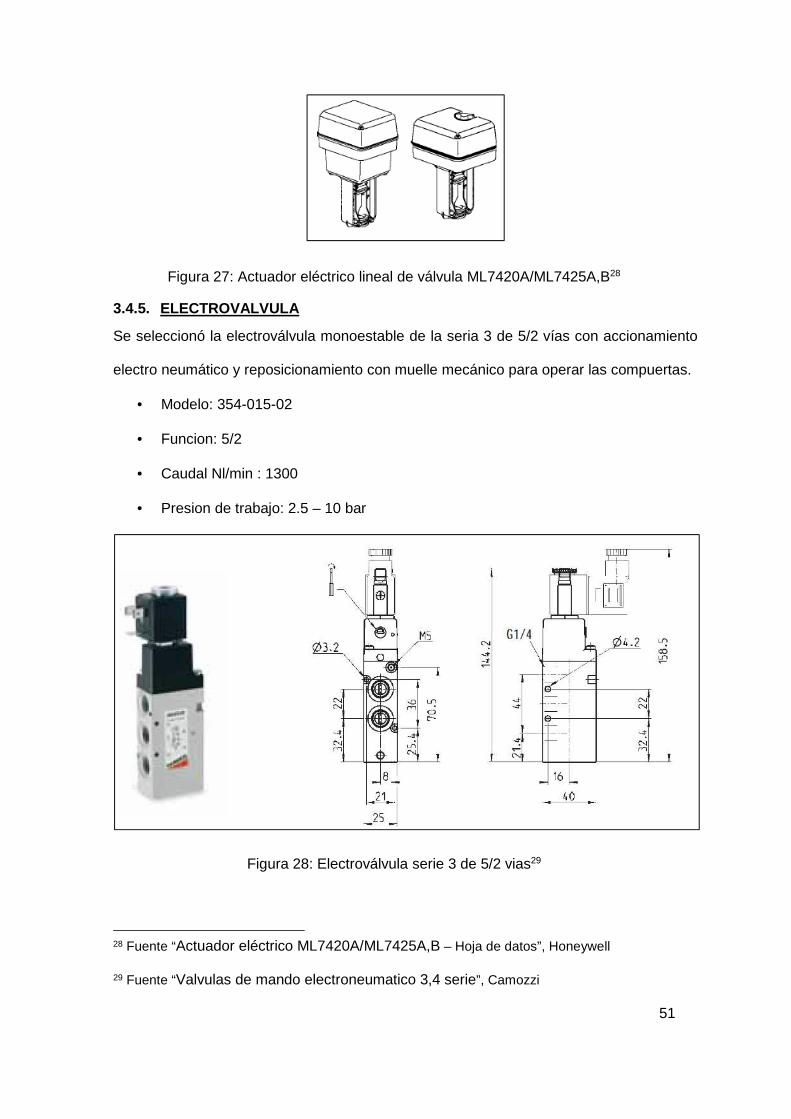
Figura 27: Actuador eléctrico lineal de válvula ML7420A/ML7425A,B28
3.4.5. ELECTROVALVULA
Se seleccionó la electroválvula monoestable de la seria 3 de 5/2 vías con accionamiento
electro neumático y reposicionamiento con muelle mecánico para operar las compuertas.
• Modelo: 354-015-02
• Funcion: 5/2
• Caudal Nl/min : 1300
• Presion de trabajo: 2.5 – 10 bar
Figura 28: Electroválvula serie 3 de 5/2 vias29
28 Fuente “Actuador eléctrico ML7420A/ML7425A,B – Hoja de datos”, Honeywell
29 Fuente “Valvulas de mando electroneumatico 3,4 serie”, Camozzi

52
3.5. DIAGRAMA DE FLUJO DEL PROCESO Y P&ID
Basados en la lista de señales (Anexo: Lista de señales e instrumentos) y tomando en
cuenta el flujo del proceso ya explicado de forma general en el capitulo 2, se desarrolló el
plano P&ID. El cual servirá posteriormente para el desarrollo de las pantallas del SCADA.
El plano se encontrará anexado en el Anexo 4: Plano P&ID.
Se ha considerado las normas ANSI/ISA-S5.1 “Instrumentation Symbols and Identification”
para el desarrollo del plano.
3.6. DISEÑO DE GABINETE DE CONTROL
Después de haber definido todas las señales que se van a controlar se procede al diseño
del gabinete de control, para mayor detalle de equipos y distribución ver el plano: “Diagrama
de montaje de gabinete de control”. El plano se encontrará en el Anexo 5: Planos del
gabinete de control.
A continuación se detallarán las características más resaltantes de los equipos utilizados
en el gabinete de control.
3.6.1. CONTROLADOR LÓGICO PROGRAMABLE (PLC)
Después de haber definido todas las señales que se van a controlar se procede al diseño
del gabinete de control, como ya se mencionó anteriormente en el ítem de Arquitectura de
Control, se empleará un PLC Controllogix de la marca Allen Bradley, para desarrollar el
control del proceso, el cual se muestra a continuación.
Figura 29: PLC Controllogix del gabinete de control. 30
30 Fuente: Desarrollo propio

53
El diseño de control plantea disponer de una redundancia de controladores, es decir que
el sistema dispondrá de dos chasis de dos controladores, si un controlador falla entrara el
otro controlador a operar en el proceso.
Figura 30: Redundancia del PLC Controllogix31
Para que se pueda realizar la redundancia se necesita que trabajes dos chasis, primario y
secundario respectivamente. Cada chasis tiene los siguientes componentes.
ITEM MODELO DESCRIPCIÓN SLOT 1 1756-PA4 Fuente de alimentación del chasis 0 2 1756-L61 Procesador 1 3 1756-RM Módulo de redundancia 2 4 1756-CN2R Módulo de comunicación Controlnet 3 5 1756-EN2T Módulo Ethernet 4
Tabla 2: Disposición de componentes en el PLC
El módulo de comunicación Controlnet es por el cual el controlador trae la comunicación
de las señales de campo, estas señales de campo están cableadas a dos chasis de
señales. El módulo de comunicación Ethernet es por el cual el procesador se comunica
con la red de control.
Las tarjetas de entradas y salidas del PLC son las siguientes:
• 1756-IF16 – Entradas Analógicas • 1756-OF8 – Salidas Analógicas • 1756-IB32 – Entradas Digitales • 1756-OW16I – Salidas Digitales
El cableado eléctrico esta detallado en el Anexo 5: Planos del gabinete de control.
31 Fuente: Desarrollo propio
54
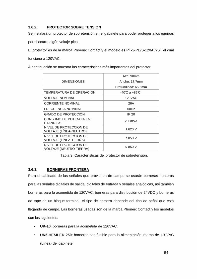
3.6.2. PROTECTOR SOBRE TENSION
Se instalará un protector de sobretensión en el gabinete para poder proteger a los equipos
por si ocurre algún voltaje pico.
El protector es de la marca Phoenix Contact y el modelo es PT-2-PE/S-120AC-ST el cual
funciona a 120VAC.
A continuación se muestra las características más importantes del protector.
DIMENSIONES
Alto: 90mm
Ancho: 17.7mm
Profundidad: 65.5mm
TEMPERATURA DE OPERACIÓN -40°C a +85°C
VOLTAJE NOMINAL 120VAC
CORRIENTE NOMINAL 26A
FRECUENCIA NOMINAL 60Hz
GRADO DE PROTECCIÓN IP 20 CONSUMO DE POTENCIA EN STAND-BY
200mVA
NIVEL DE PROTECCION DE VOLTAJE (LÍNEA-NEUTRO)
≤ 620 V
NIVEL DE PROTECCION DE VOLTAJE (LÍNEA-TIERRA) ≤ 850 V
NIVEL DE PROTECCION DE VOLTAJE (NEUTRO-TIERRA)
≤ 850 V
Tabla 3: Características del protector de sobretensión.
3.6.3. BORNERAS FRONTERA
Para el cableado de las señales que provienen de campo se usarán borneras fronteras
para las señales digitales de salida, digitales de entrada y señales analógicas, así también
borneras para la acometida de 120VAC, borneras para distribución de 24VDC y borneras
de tope de un bloque terminal, el tipo de bornera depende del tipo de señal que está
llegando de campo. Las borneras usadas son de la marca Phoneix Contact y los modelos
son los siguientes:
• UK-10: borneras para la acometida de 120VAC.
• UK5-HESILED 250 : borneras con fusible para la alimentación interna de 120VAC
(Línea) del gabinete
55
• UK-5N: borneras de paso para la alimentación interna de 120VAC (Neutro) del
gabinete y para la alimentación interna de 24VDC (Negativo) del gabinete.
• UK5-HESILED 24 : borneras con fusible para la alimentación interna de 24VDC
(Positivo) del gabinete.
• UKK-5-HESI : borneras de dos pisos con fusible para entradas digitales de
instrumentos de campo y salidas digitales del PLC.
• VIOK 1,5-3D/PE: borneras de 3 pisos con 1 tierra para entradas analógicas de
instrumentos de campo.
• DOK 1.5-2D: borneras de 2 pisos con 1 tierra para módulo HART.
3.6.4. OTROS MATERIALES INTERNOS
Adicionalmente a los equipos ya mencionados anteriormente dentro del gabinete se
adicionarán barras de tierra de cobre para el aterramiento de los equipos y del gabinete,
estas barras de tierra estarán montadas con aisladores para así poder mantener la tierra
aislada.
Se instalará canaletas ranuradas de material PVC, las cuales se usan para la distribución
de cables internos del gabinete.
Para el montaje de los equipos se instalarán rieles DIN de 35mm, en los cuales se hará la
distribución de borneras y de los equipos que se van a montar dentro del gabinete.
Para la alimentación del gabinete, ya sea de 120VAC o de 24VDC se están considerando
llaves termo magnéticas para poder tener un control de la alimentación interna, ya sea para
un mantenimiento de módulos o para la distribución hacia nuevos componentes que
puedan instalarse futuramente.
3.6.5. GABINETE
Para el montaje de todos los componentes se ha escogido un gabinete de la marca Rittal
modelo AE- 1180.500, de material de chapa de acero, el cual cuenta con una puerta con
56
bisagras, cerrada en todo el contorno, placa entrada de cables en el suelo de la caja y
placa de montaje.
La superficie del armario y de la puerta son de imprimación por inmersión, exterior
texturizado, pintura estructurada y de la placa de montaje es galvanizada, el color del
gabinete es RAL 7035
Las dimensiones son las siguientes:
• Altura: 2200mm
• Ancho: 1800mm
• Profundidad: 600mm
El gabinete tiene un grado de protección IP66 con protección de polvo y agua.
3.7. PROGRAMACIÓN DE PLC
Para la programación del PLC se empleó el software RSLogix 5000 del fabricante Rockwell
Automation.
En este capítulo se indicara la configuración y flujo del programa a través de las subrutinas
desarrolladas.
3.7.1. CONFIGURACIÓN I/O
Primero se ha configurado los módulos que se van a emplear en el gabinete de control, es
decir los módulos que componen el PLC CompactLogix.

57
Figura 31: Configuración de módulos32
En la parte encerrada por un círculo rojo se puede observar que se han agregado los
módulos del PLC CompactLogix, también se agregó el variador de velocidad para poder
incluir las señales que se generan en el variador para el control del motor desde el PLC.
3.7.2. CONFIGURACIÓN DE TAGS DE INSTRUMENTOS
Una vez que se tienen configurado los módulos del PLC se procede a configurar los tags
que se emplearán en el controlador.
32 Fuente: Desarrollo propio

58
Figura 32: Configuración de tags. 33
En la figura se puede observar cómo quedan configurados los tags de los instrumentos
dentro del programa, cada tag tiene su descripción, tipo de dato y su valor.
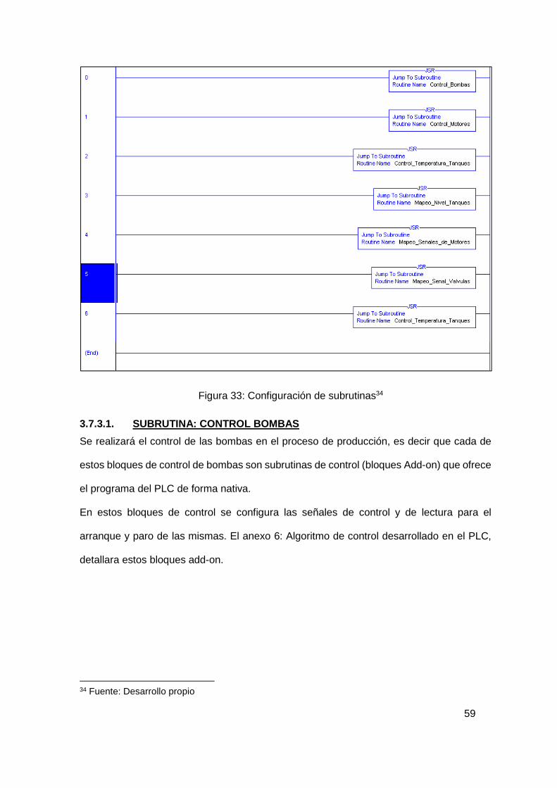
3.7.3. CONFIGURACIÓN DE SUBRUTINAS
Dentro de las tareas que realizará el PLC encontramos el programa Principal donde
desarrollaremos la lógica de control. Dentro del “MainProgram” encontraremos la rutina
principal “MainRoutine”, en esta rutina no se desarrollará lógica solo se direccionará a las
siguientes subrutinas.
33 Fuente: Desarrollo propio
59
Figura 33: Configuración de subrutinas34
3.7.3.1. SUBRUTINA: CONTROL BOMBAS
Se realizará el control de las bombas en el proceso de producción, es decir que cada de
estos bloques de control de bombas son subrutinas de control (bloques Add-on) que ofrece
el programa del PLC de forma nativa.
En estos bloques de control se configura las señales de control y de lectura para el
arranque y paro de las mismas. El anexo 6: Algoritmo de control desarrollado en el PLC,
detallara estos bloques add-on.
34 Fuente: Desarrollo propio

60
Figura 34: Subrutina: Control bombas35
3.7.3.2. SUBRUTINA: CONTROL MOTORES
Se realizará el control de los motores para el proceso de producción, es decir que cada de
estos bloques de control de motores son subrutinas de control (bloques Add-on) que ofrece
el programa del PLC de forma nativa.
En estos bloques de control se configura las señales de control y de lectura para el
arranque y paro de las bombas. El anexo 6: Algoritmo de control desarrollado en el PLC,
detallara estos bloques add-on.
35 Fuente: Desarrollo propio

61
Figura 35: Subrutina: Control motores36
3.7.3.3. SUBRUTINA: CONTROL TEMPERATURA DE TANQUES
El control de los lazos de control de temperatura en los tanques se realizara en esta
subrutina, en esta subrutina se regularan las válvulas de ingreso del fluido de intercambio
de calor por el serpentín en los tanques.
Los bloques PIDE, son los add-ons que están dispuestos por parte del programa para el
control de lazos, y las salidas de control hacia la válvula reguladora de fluido termino son
relacionadas al bloque add-on P_AOut.
36 Fuente: Desarrollo propio

62
Figura 36: Subrutina: Control temperatura de tanques37
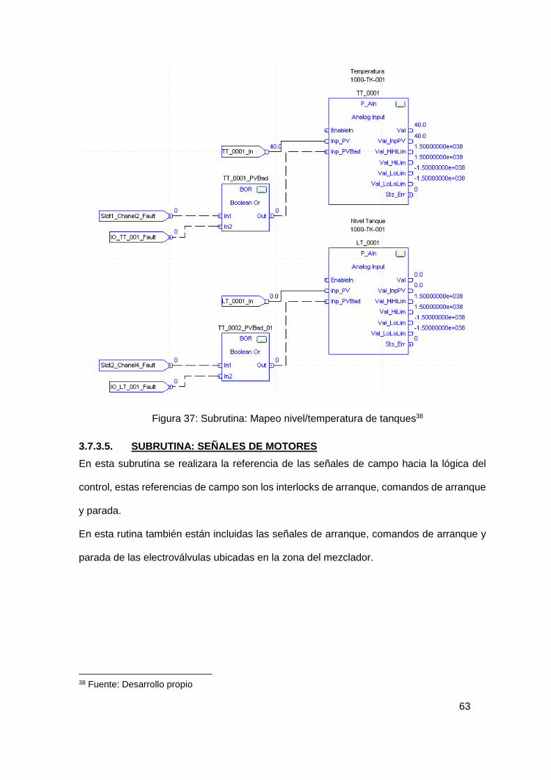
3.7.3.4. SUBRUTINAS: MAPEO NIVEL/TEMPERATURA DE TAN QUES
En estas subrutinas se realizan la lectura de señales de nivel y temperatura dados por los
instrumentos de campo y el procesamiento de la señal en la zona de tanques, para lo cual
se configura el bloque add-on P_Ain.
Este bloque add-on está relacionado a los indicadores en el SCADA, el cual permite que la
modificación del escalamiento pueda realizarse desde dicho HMI.
37 Fuente: Desarrollo propio
63
Figura 37: Subrutina: Mapeo nivel/temperatura de tanques38
3.7.3.5. SUBRUTINA: SEÑALES DE MOTORES
En esta subrutina se realizara la referencia de las señales de campo hacia la lógica del
control, estas referencias de campo son los interlocks de arranque, comandos de arranque
y parada.
En esta rutina también están incluidas las señales de arranque, comandos de arranque y
parada de las electroválvulas ubicadas en la zona del mezclador.
38 Fuente: Desarrollo propio

64
Figura 38: Subrutina: Mapeo señales de motores39
39 Fuente: Desarrollo propio
65
CAPÍTULO 4
RESULTADOS En el capítulo de resultados se explicará como el sistema de control impacta en el
desarrollo de los trabajos de operación en la planta de producción de asfalto.
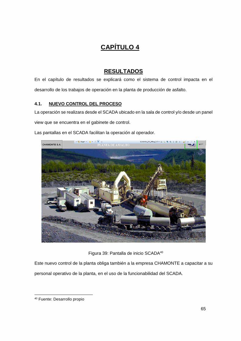
4.1. NUEVO CONTROL DEL PROCESO
La operación se realizara desde el SCADA ubicado en la sala de control y/o desde un panel
view que se encuentra en el gabinete de control.
Las pantallas en el SCADA facilitan la operación al operador.
Figura 39: Pantalla de inicio SCADA40
Este nuevo control de la planta obliga también a la empresa CHAMONTE a capacitar a su
personal operativo de la planta, en el uso de la funcionabilidad del SCADA.
40 Fuente: Desarrollo propio

66
4.1.1. USUARIOS DE CONTROL DE LA PLANTA
El control de los operadores será de forma jerárquica, con los siguientes tipos de usuarios:
• Operador • Supervisor • Administrador • Mantenimiento
Es decir la operación será controlada, se tendrá el registro de operación de que usuario ha
realizado algún cambio en la planta, al ingresar el usuario deberá colocar su contraseña.
Figura 40: Modo de ingreso41
4.1.2. MONITOREO DE VARIABLES
Las variables que antes el operador las visualizaba por indicadores en campo, las podrá
visualizar a través de pantallas emergentes que tendrán más opciones de trabajo, como
ver las variables en el tiempo y visualización de alarmas.
41 Fuente: Desarrollo propio

67
Figura 41: Monitoreo de variables42
4.1.3. VISUALIZACION DE ALARMAS
Se tendrá registros de las fallas que pueden ocurrir en la planta de asfalto, monitorearlas y tomar acciones correctivas.
Figura 42: Monitoreo de alarmas43
42 Fuente: Desarrollo propio
43 Fuente: Desarrollo propio

68
4.2. VENTANA EMERGENTE DE TENDENCIAS
Muestra la tendencia de los transmisores, es decir cómo va funcionando o que va indicando
la variable a través del tiempo.
Figura 43: Tendencia de las variables44
4.3. OPERACIÒN DE LOS MOTORES Y VALVULAS
El arranque de los motores se podrá realizar a partir del SCADA, en las pantallas de
operación estarán ubicados los motores, el operador solo deberá generar un click sobre
cualquiera de los motores para poder acceder al menú de trabajo de estos.
Figura 44: Pantalla del proceso45
44 Fuente: Desarrollo propio
45 Fuente: Desarrollo propio

69
Figura 45: Ventana emergente Motor46
Para las válvulas el trabajo es similar, el operador podrá realizar todos los trabajosa partir
de la nueva ventana emergente, para el caso de las válvulas regulables que obedecen a
un lazo de control PID la ventana estará trabajada para operar automáticamente con los
parámetros PID o de forma manual, es decir colocando la apertura de la valvula.
Figura 46: Ventana emergente Válvula On-Off47
46 Fuente: Desarrollo propio
47 Fuente: Desarrollo propio
70
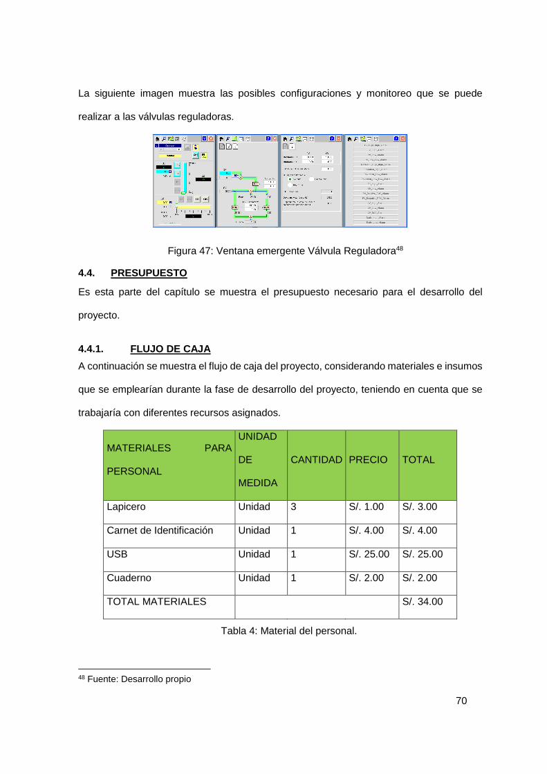
La siguiente imagen muestra las posibles configuraciones y monitoreo que se puede
realizar a las válvulas reguladoras.
Figura 47: Ventana emergente Válvula Reguladora48
4.4. PRESUPUESTO Es esta parte del capítulo se muestra el presupuesto necesario para el desarrollo del
proyecto.
4.4.1. FLUJO DE CAJA
A continuación se muestra el flujo de caja del proyecto, considerando materiales e insumos
que se emplearían durante la fase de desarrollo del proyecto, teniendo en cuenta que se
trabajaría con diferentes recursos asignados.
MATERIALES PARA
PERSONAL
UNIDAD
DE
MEDIDA
CANTIDAD PRECIO TOTAL
Lapicero Unidad 3 S/. 1.00 S/. 3.00
Carnet de Identificación Unidad 1 S/. 4.00 S/. 4.00
USB Unidad 1 S/. 25.00 S/. 25.00
Cuaderno Unidad 1 S/. 2.00 S/. 2.00
TOTAL MATERIALES S/. 34.00
Tabla 4: Material del personal.
48 Fuente: Desarrollo propio

71
INSUMOS
UNIDAD
DE
MEDIDA
CANTIDAD PRECIO TOTAL
Papel bond A4 Millar 1 S/. 23.00 S/. 23.00
Papel A3 Millar 1 S/. 35.00 S/. 35.00
Tinta impresora Cartucho 4 S/. 30.00 S/. 120.00
Pizarra Unidad 1 S/. 35.00 S/. 35.00
Plumon Unidad 4 S/. 1.50 S/. 4.50
Mota Unidad 1 S/. 2.00 S/. 2.00
TOTAL INSUMOS S/. 219.50
Tabla 5: Insumos empleados para el proyecto.
EQUIPOS
UNIDAD
DE
MEDIDA
CANTIDAD PRECIO TOTAL
Laptop Unidad 4 S/. 2,500.00 S/. 10,000.00
Impresora multifuncional Brother Unidad 1 S/. 300.00 S/. 300.00
PC de escritorio Unidad 2 S/. 1,000.00 S/. 2,000.00
TOTAL EQUIPOS S/. 12,300.00
TOTAL GENERAL S/. 12,553.50
Tabla 6: Equipos empleados para el proyecto.

72
Tabla 7: Presupuesto material humano
EGRESO DEL PRESUPUESTO DEL PROYECTO
MES 1 2 3 4
INGRESOS Ventas/Beneficios - - - - EGRESOS Inversi ón Microsoft Office S/. 1,500.00 Software Rockwell Automation S/. 2,500.00 Software AutoCAD S/. 16,000.00 Gastos Generales Equipos y materiales S/. 12,553.50 Subcontratos - S/. 0.00 Recursos Humanos
Gerente del Proyecto S/. 4,000.00 S/. 4,000.00 S/. 4,000.00 S/.
4,000.00
Lider del Proyecto S/. 5,200.00 S/. 5,200.00 S/. 5,200.00 S/.
5,200.00 Instrumentista S/. 3,600.00 S/. 3,600.00 S/. 3,600.00 Ingeniero de control S/. 3,600.00 S/. 3,600.00 S/. 3,600.00
Programador S/. 2,000.00 S/.
2,000.00 Proyectista S/. 2,400.00 S/. 2,400.00 S/. 2,400.00 Dibujante S/. 1,600.00 S/. 1,600.00 S/. 1,600.00
TOTAL PRESUPUESTO S/. 52,953.50 S/.
20,400.00 S/.
22,400.00 S/.
11,200.00
TOTAL ACUMULADO S/. 52,952.00 S/.
73,352.00 S/.
95,752.00 S/.
106,952.00
Tabla 8: Egreso del presupuesto del proyecto
73
CONCLUSIONES • Mi conclusión inicial plantea la necesidad de evolucionar la concepción de la
operación y proyectarlo a los nuevos escenarios tecnológicos competitivos, en
donde no solo el área de operación se vea involucrada sino también elaborar
nuevos planes de mantenimiento a futuro.
• El uso de PLC y software para la interacción con autómatas, permite desarrollar
interfaces hombre-máquina, más accesibles y de manejo simplificado, dando
notoriedad en el flujo de información como uno de los principales motivos para el
diseño del mismo. El desarrollo de proyectos de este tipo, permite visualizar pautas
en el seguimiento de automatización y control de procesos.
• El uso del PLC Controllogix de la marca Rockwell Automation como parte de la
automatización reduce el número de componentes en cableado y hace más amplia
una gama de opciones para el desarrollo del diseño. Con el PLC se consigue un
tablero de control más ordenado que hace la conexión accesible al tablero que
comunica a los elementos del proceso, en este caso una planta de producción de
asfalto; como válvulas, transmisores, así como electro válvulas, motores y bombas.
• El software Factory Talk View muestra gráficamente el diseño físico del proceso
con todos sus componentes, así como el control y monitoreo sin intervención directa
del operador en el proceso.
• Así pues, después de recabar información en lo investigado y con el material
disponible, se pudo realizar la ingeniería de un sistema de control de producción de
asfalto.

74
ANEXO 1: PLANO ARQUITECTURA DE CONTROL

75
ANEXO 2: PLOT PLAN

76
ANEXO 3: LISTA DE SEÑALES E INSTRUMENTOS

77
ANEXO 4: PLANOS P&ID

78
ANEXO 5: PLANOS DEL GABINETE DE CONTROL

79
ANEXO 6: ALGORITO DE CONTROL DESAROLLADO EN EL PLC
80
GLOSARIO Campo: Lugar donde se encuentra la instrumentación.
Chasis: Dispositivo electrónico en el cual se instalan los módulos de entradas y salidas,
comunicaciones, procesadores de la plataforma CompactLogix de Allen Bradley.
Especificación: Documento que define de forma precisa y verificable, los requisitos de
diseño, comportamiento u otras características de un sistema o elemento de un sistema.
Módulo de entrada y salidas: Dispositivos que reciben o envían señales discretas o
analógicas desde campo hacia el PLC o viceversa.
Módulo de comunicaciones: Dispositivos encargados de comunicar el sistema de control
dentro de una plataforma de comunicaciones estándar como ControlNet o Ethernet.
Panel de operador: Interfaz hombre-máquina que brinda al operador un entorno gráfico
local para la supervisión y control del proceso.
Popup: Ventana que emerge automáticamente en la pantalla.
PLC: Controlador Lógico Programable, puede ser modular o compacto, se realiza la
programación en el CPU del mismo y este hace el control de las I/Os encontradas.

81
BIBLIOGRAFÍA Alfonso Lopez Cespedez, J. C. (2007). Diseño de una metodologia de automatizacion y
control para los procesos de dosificacion, mezcla y carga de una planta de asfalto.
Bogota, Colombia: Universidad de la Salle.
Asociación de la industria electrica y electronica Chile. (2013). Obtenido de Asociación de
la industria electrica y electronica Chile:
http://www.aie.cl/files/file/comites/ca/articulos/agosto-06.pdf
Corrales Paucar, L. (2007). Interfaces de comunicación industrial. En L. Corrales Paucar,
Interfaces de comunicación industrial (págs. 38-88). Quito.
Creus Solé, A. (1997). Instrumentación industrial. Barcelona, España: ALFAOMEGA
GRUPO EDITOR S.A.
García, D. (2001). infoPLC Actualidad y recursos sobre automatización. Obtenido de
infoPLC Actualidad y recursos sobre automatización: http://www.infoplc.net/
Hernández, G. J. (s.f.). Control difuso basado en PC, aplicado a una planta de Asfalto.
Buenos Aires, Argentina.
Industrias Pirelli. (s.f.). Manual de cálculo de cintas transportadoras. Bella Vista.
Instrumentación y Control. (1 de Enero de 2012). Obtenido de Instrumentación y Control:
http://www.instrumentacionycontrol.net/
Internacional SA. (1 de 8 de 2015). Ablisa. Obtenido de www.ablisa.com
Ministerio de Transportes y Comunicaciones. (Abril 2012). Plan estrategico sectorial
multianual sector transportes y comunicaciones 2012-2016. Lima.
Ogata. (2010). Ingenieria de Control Modera 5º Edicion. Buenos Aires, Argentina:
PEARSON.
Ogata, K. (2003). Ingeniería de control moderna. Madrid: Pearson Educación S.A.
Pere Ponsa, A. G. (2007). Diseño y Automatizacion Industrial. Cataluña, España:
Universidad Politecnica de Cataluña.
82
Schneider Electric España, S.A. (2008). Guia de Diseño de Instalaciones Eléctricas.
Barcelona: Tecfoto.
Tremante P, B. E. (2007). Una vision de la teoria difusa y los sistemas difusos. Actualidad
y nuevas tendencias, 121-136.
Wikipedia. (26 de Mayo de 2012). Obtenido de https://es.wikipedia.org/wiki/Asfalto
Wikipedia. (12 de Diciembre de 2014). Obtenido de Wikipedia:
http://es.wikipedia.org/wiki/Cinta_transportadora
Wikipedia. (12 de Dciciembre de 2014). Wikipedia la encicclopedia libre. Obtenido de
Wikipedia la encicclopedia libre: http://es.wikipedia.org/wiki/Cinta_transportadora

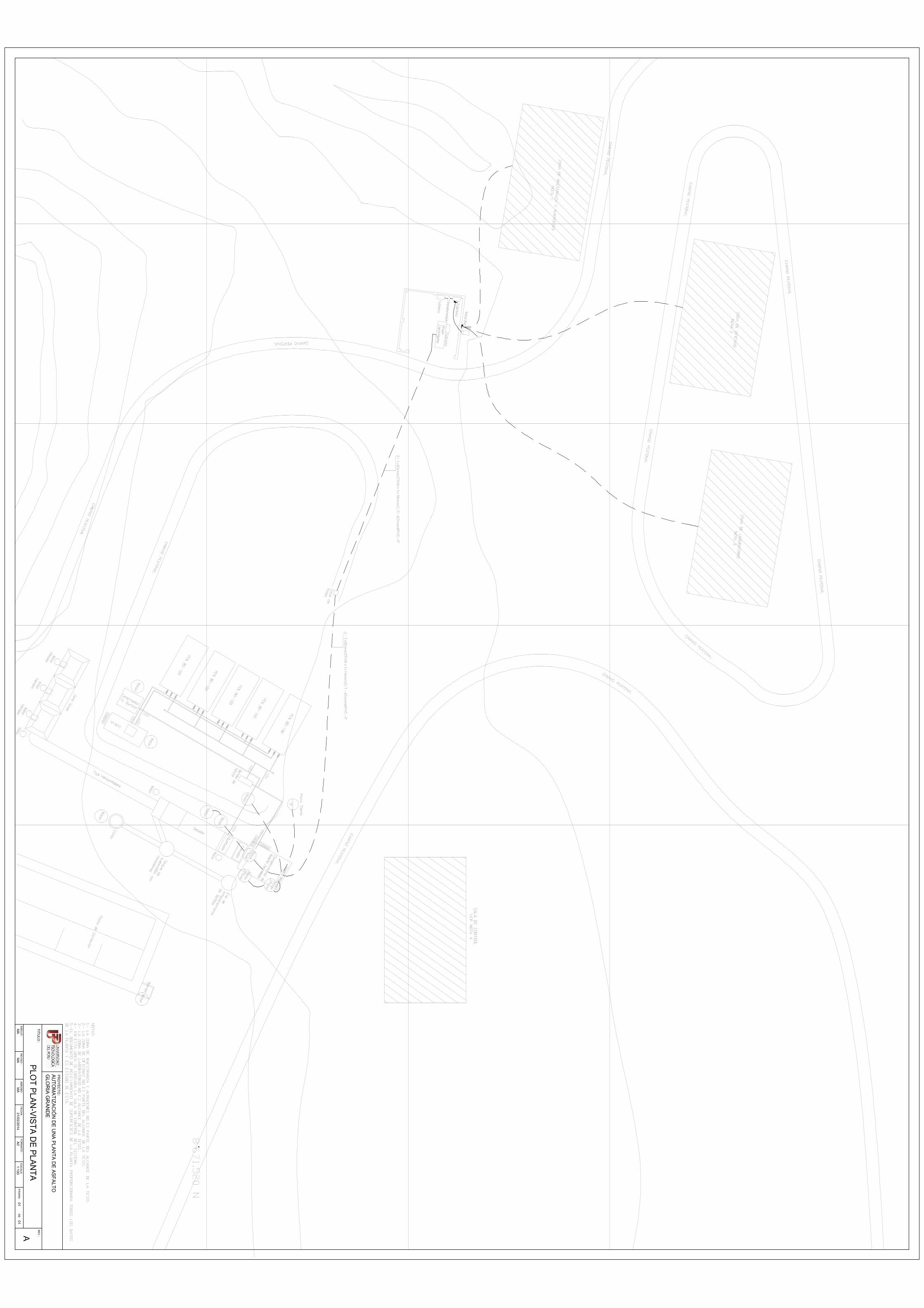
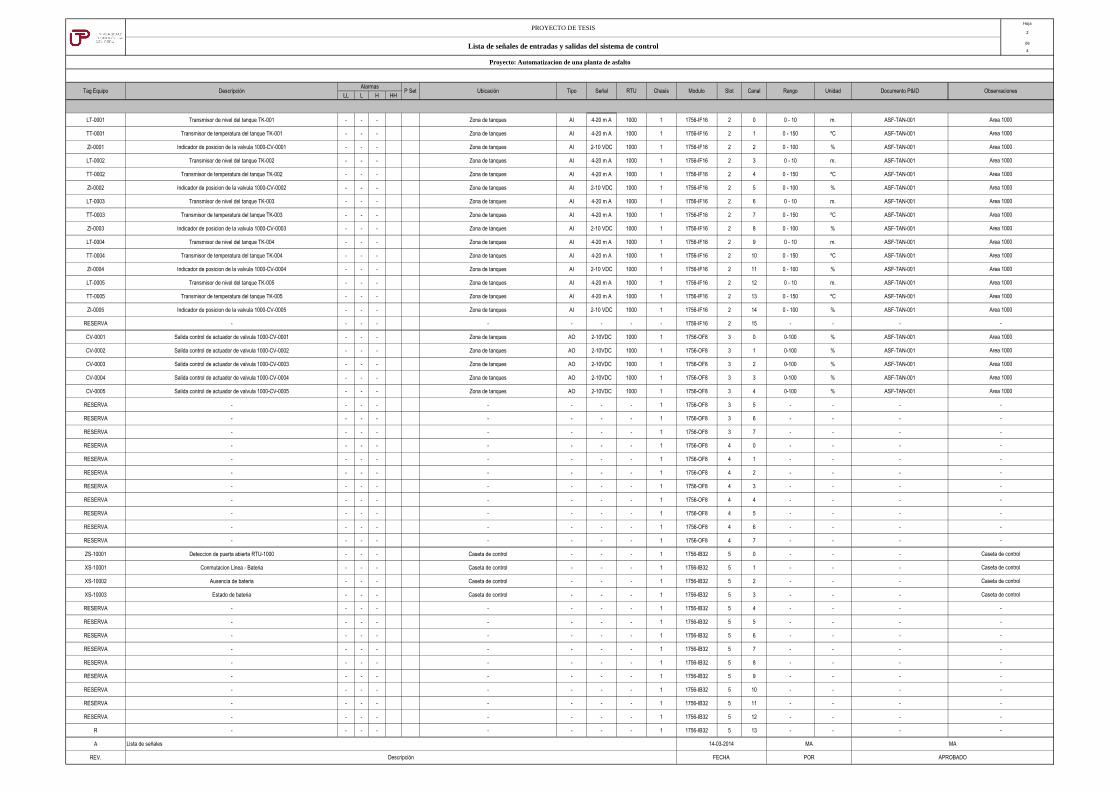
Hoja
2
de
4
LL L H HH
LT-0001 Transmisor de nivel del tanque TK-001 - - - Zona de tanques AI 4-20 m A 1000 1 1756-IF16 2 0 0 - 10 m. ASF-TAN-001
TT-0001 Transmisor de temperatura del tanque TK-001 - - - Zona de tanques AI 4-20 m A 1000 1 1756-IF16 2 1 0 - 150 ºC ASF-TAN-001
ZI-0001 Indicador de posicion de la valvula 1000-CV-0001 - - - Zona de tanques AI 2-10 VDC 1000 1 1756-IF16 2 2 0 - 100 % ASF-TAN-001
LT-0002 Transmisor de nivel del tanque TK-002 - - - Zona de tanques AI 4-20 m A 1000 1 1756-IF16 2 3 0 - 10 m. ASF-TAN-001
TT-0002 Transmisor de temperatura del tanque TK-002 - - - Zona de tanques AI 4-20 m A 1000 1 1756-IF16 2 4 0 - 150 ºC ASF-TAN-001
ZI-0002 Indicador de posicion de la valvula 1000-CV-0002 - - - Zona de tanques AI 2-10 VDC 1000 1 1756-IF16 2 5 0 - 100 % ASF-TAN-001
LT-0003 Transmisor de nivel del tanque TK-003 - - - Zona de tanques AI 4-20 m A 1000 1 1756-IF16 2 6 0 - 10 m. ASF-TAN-001
TT-0003 Transmisor de temperatura del tanque TK-003 - - - Zona de tanques AI 4-20 m A 1000 1 1756-IF16 2 7 0 - 150 ºC ASF-TAN-001
ZI-0003 Indicador de posicion de la valvula 1000-CV-0003 - - - Zona de tanques AI 2-10 VDC 1000 1 1756-IF16 2 8 0 - 100 % ASF-TAN-001
LT-0004 Transmisor de nivel del tanque TK-004 - - - Zona de tanques AI 4-20 m A 1000 1 1756-IF16 2 9 0 - 10 m. ASF-TAN-001
TT-0004 Transmisor de temperatura del tanque TK-004 - - - Zona de tanques AI 4-20 m A 1000 1 1756-IF16 2 10 0 - 150 ºC ASF-TAN-001
ZI-0004 Indicador de posicion de la valvula 1000-CV-0004 - - - Zona de tanques AI 2-10 VDC 1000 1 1756-IF16 2 11 0 - 100 % ASF-TAN-001
LT-0005 Transmisor de nivel del tanque TK-005 - - - Zona de tanques AI 4-20 m A 1000 1 1756-IF16 2 12 0 - 10 m. ASF-TAN-001
TT-0005 Transmisor de temperatura del tanque TK-005 - - - Zona de tanques AI 4-20 m A 1000 1 1756-IF16 2 13 0 - 150 ºC ASF-TAN-001
ZI-0005 Indicador de posicion de la valvula 1000-CV-0005 - - - Zona de tanques AI 2-10 VDC 1000 1 1756-IF16 2 14 0 - 100 % ASF-TAN-001
RESERVA - - - - - - - - - 1756-IF16 2 15 - - -
CV-0001 Salida control de actuador de valvula 1000-CV-0001 - - - Zona de tanques AO 2-10VDC 1000 1 1756-OF8 3 0 0-100 % ASF-TAN-001
CV-0002 Salida control de actuador de valvula 1000-CV-0002 - - - Zona de tanques AO 2-10VDC 1000 1 1756-OF8 3 1 0-100 % ASF-TAN-001
CV-0003 Salida control de actuador de valvula 1000-CV-0003 - - - Zona de tanques AO 2-10VDC 1000 1 1756-OF8 3 2 0-100 % ASF-TAN-001
CV-0004 Salida control de actuador de valvula 1000-CV-0004 - - - Zona de tanques AO 2-10VDC 1000 1 1756-OF8 3 3 0-100 % ASF-TAN-001
CV-0005 Salida control de actuador de valvula 1000-CV-0005 - - - Zona de tanques AO 2-10VDC 1000 1 1756-OF8 3 4 0-100 % ASF-TAN-001
RESERVA - - - - - - - - 1 1756-OF8 3 5 - - -
RESERVA - - - - - - - - 1 1756-OF8 3 6 - - -
RESERVA - - - - - - - - 1 1756-OF8 3 7 - - -
RESERVA - - - - - - - - 1 1756-OF8 4 0 - - -
RESERVA - - - - - - - - 1 1756-OF8 4 1 - - -
RESERVA - - - - - - - - 1 1756-OF8 4 2 - - -
RESERVA - - - - - - - - 1 1756-OF8 4 3 - - -
RESERVA - - - - - - - - 1 1756-OF8 4 4 - - -
RESERVA - - - - - - - - 1 1756-OF8 4 5 - - -
RESERVA - - - - - - - - 1 1756-OF8 4 6 - - -
RESERVA - - - - - - - - 1 1756-OF8 4 7 - - -
ZS-10001 Deteccion de puerta abierta RTU-1000 - - - Caseta de control - - - 1 1756-IB32 5 0 - - -
XS-10001 Conmutacion Linea - Bateria - - - Caseta de control - - - 1 1756-IB32 5 1 - - -
XS-10002 Ausencia de bateria - - - Caseta de control - - - 1 1756-IB32 5 2 - - -
XS-10003 Estado de bateria - - - Caseta de control - - - 1 1756-IB32 5 3 - - -
RESERVA - - - - - - - - 1 1756-IB32 5 4 - - -
RESERVA - - - - - - - - 1 1756-IB32 5 5 - - -
RESERVA - - - - - - - - 1 1756-IB32 5 6 - - -
RESERVA - - - - - - - - 1 1756-IB32 5 7 - - -
RESERVA - - - - - - - - 1 1756-IB32 5 8 - - -
RESERVA - - - - - - - - 1 1756-IB32 5 9 - - -
RESERVA - - - - - - - - 1 1756-IB32 5 10 - - -
RESERVA - - - - - - - - 1 1756-IB32 5 11 - - -
RESERVA - - - - - - - - 1 1756-IB32 5 12 - - -
R - - - - - - - - 1 1756-IB32 5 13 - - -
A
REV.
Lista de señales
Descripción
Area 1000
Area 1000
Area 1000
MA
POR
Area 1000
Area 1000
-
Area 1000
Area 1000
Area 1000
Area 1000
Area 1000
Area 1000
Area 1000
14-03-2014
FECHA
Area 1000
Area 1000
-
Caseta de control
-
-
Caseta de control
APROBADO
MA
-
-
-
-
Area 1000
-
Area 1000
Area 1000
Caseta de control
-
-
-
-
-
-
-
Area 1000
Area 1000
Area 1000
-
Documento P&ID ObservacionesTag Equipo Modulo RangoUbicación
-
-
-
-
-
Caseta de control
PROYECTO DE TESIS
Lista de señales de entradas y salidas del sistema de control
Slot CanalAlarmas
Tipo RTU ChasisSeñal
Proyecto: Automatizacion de una planta de asfalto
Descripción P Set Unidad

Hoja
3
de
4
LL L H HH
RESERVA - - - - - - - - 1 1756-IB32 5 14 - - -
RESERVA - - - - - - - - 1 1756-IB32 5 15 - - -
RESERVA - - - - - - - - 1 1756-IB32 5 16 - - -
RESERVA - - - - - - - - 1 1756-IB32 5 17 - - -
RESERVA - - - - - - - - 1 1756-IB32 5 18 - - -
RESERVA - - - - - - - - 1 1756-IB32 5 19 - - -
RESERVA - - - - - - - - 1 1756-IB32 5 20 - - -
RESERVA - - - - - - - - 1 1756-IB32 5 21 - - -
RESERVA - - - - - - - - 1 1756-IB32 5 22 - - -
RESERVA - - - - - - - - 1 1756-IB32 5 23 - - -
RESERVA - - - - - - - - 1 1756-IB32 5 24 - - -
RESERVA - - - - - - - - 1 1756-IB32 5 25 - - -
RESERVA - - - - - - - - 1 1756-IB32 5 26 - - -
RESERVA - - - - - - - - 1 1756-IB32 5 27 - - -
RESERVA - - - - - - - - 1 1756-IB32 5 28 - - -
RESERVA - - - - - - - - 1 1756-IB32 5 29 - - -
RESERVA - - - - - - - - 1 1756-IB32 5 30 - - -
RESERVA - - - - - - - - 1 1756-IB32 5 31 - - -
M-001 Salida activacion del motor del HYWAY - - - Zona del mezclador DO NA 1000 1 1756-OW16I 6 0 - - -
M-002 Salida activacion del motor del Bunker - - - Zona del mezclador DO NA 1000 1 1756-OW16I 6 1 - - -
M-003 Salida activacion del motor faja 1 - - - Zona del mezclador DO NA 1000 1 1756-OW16I 6 2 - - -
M-004 Salida activacion del motor vibratorio 1 - - - Zona del mezclador DO NA 1000 1 1756-OW16I 6 3 - - -
M-005 Salida activacion del motor vibratorio 2 - - - Zona del mezclador DO NA 1000 1 1756-OW16I 6 4 - - -
M-006 Salida activacion del motor vibratorio 3 - - - Zona del mezclador DO NA 1000 1 1756-OW16I 6 5 - - -
M-007 Salida activacion del motor faja 2 - - - Zona del mezclador DO NA 1000 1 1756-OW16I 6 6 - - -
M-008 Salida activacion del motor secador 1 - - - Zona del mezclador DO NA 1000 1 1756-OW16I 6 7 - - -
M-009 Salida activacion del motor secador 2 - - - Zona del mezclador DO NA 1000 1 1756-OW16I 6 8 - - -
M-010 Salida activacion del motor del elevador - - - Zona del mezclador DO NA 1000 1 1756-OW16I 6 9 - - -
M-011 Salida activacion del motor succion de aridos - - - Zona del mezclador DO NA 1000 1 1756-OW16I 6 10 - - -
M-012 Salida activacion del motor de la zaranda - - - Zona del mezclador DO NA 1000 1 1756-OW16I 6 11 - - -
M-013 Salida activacion del motor del mezclador - - - Zona del mezclador DO NA 1000 1 1756-OW16I 6 12 - - -
P-001 Salida activacion de la bomba de asfalto - - - Zona del mezclador DO NA 1000 1 1756-OW16I 6 13 - - -
P-002 Salida de activacion de la bomba de aire - - - Zona del mezclador DO NA 1000 1 1756-OW16I 6 14 - - -
P-003 Salida de activacion de la bomba de agua - - - Zona del mezclador DO NA 1000 1 1756-OW16I 6 15 - - -
XC-001 Salida activacion de electrovalvula XC-001 - - - Zona del mezclador DO NA 1000 1 1756-OW16I 7 0 - - -
XC-002 Salida activacion de electrovalvula XC-002 - - - Zona del mezclador DO NA 1000 1 1756-OW16I 7 1 - - -
XC-003 Salida activacion de electrovalvula XC-003 - - - Zona del mezclador DO NA 1000 1 1756-OW16I 7 2 - - -
XC-004 Salida activacion de electrovalvula XC-004 - - - Zona del mezclador DO NA 1000 1 1756-OW16I 7 3 - - -
RESERVA - - - - - - - - 1 1756-OW16I 7 4 - - -
RESERVA - - - - - - - - 1 1756-OW16I 7 5 - - -
RESERVA - - - - - - - - 1 1756-OW16I 7 6 - - -
RESERVA - - - - - - - - 1 1756-OW16I 7 7 - - -
RESERVA - - - - - - - - 1 1756-OW16I 7 8 - - -
RESERVA - - - - - - - - 1 1756-OW16I 7 9 - - -
RESERVA - - - - - - - - 1 1756-OW16I 7 10 - - -
RESERVA - - - - - - - - 1 1756-OW16I 7 11 - - -
A
REV.
PROYECTO DE TESIS
Lista de señales de entradas y salidas del sistema de control
Proyecto: Automatizacion de una planta de asfalto
Tag Equipo DescripciónAlarmas
P Set Ubicación Tipo Señal RTU Unidad Documento P&ID Observaciones
-
Chasis Modulo Slot Canal Rango
-
-
-
-
-
Area 1000
-
-
-
-
-
-
-
-
-
-
-
-
Area 1000
Area 1000
Area 1000
Area 1000
Area 1000
Area 1000
Area 1000
Area 1000
Area 1000
Area 1000
Area 1000
Area 1000
-
Area 1000
Area 1000
Area 1000
Area 1000
Area 1000
Area 1000
Area 1000
-
-
-
-
Descripción FECHA POR APROBADO
-
-
-
Lista de señales 14-03-2014 MA MA
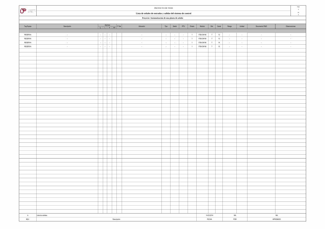
Hoja
3
de
4
LL L H HH
RESERVA - - - - - - - - 1 1756-OW16I 7 12 - - -
RESERVA - - - - - - - - 1 1756-OW16I 7 13 - - -
RESERVA - - - - - - - - 1 1756-OW16I 7 14 - - -
RESERVA - - - - - - - - 1 1756-OW16I 7 15 - - -
A
REV.
PROYECTO DE TESIS
Lista de señales de entradas y salidas del sistema de control
Proyecto: Automatizacion de una planta de asfalto
Tag Equipo DescripciónAlarmas
P Set Ubicación Tipo Señal RTU Unidad Documento P&ID ObservacionesChasis Modulo Slot Canal Rango
-
-
-
-
Descripción FECHA POR APROBADO
Lista de señales 14-03-2014 MA MA

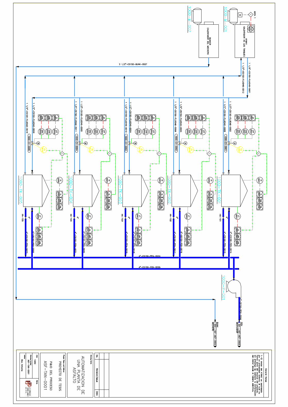
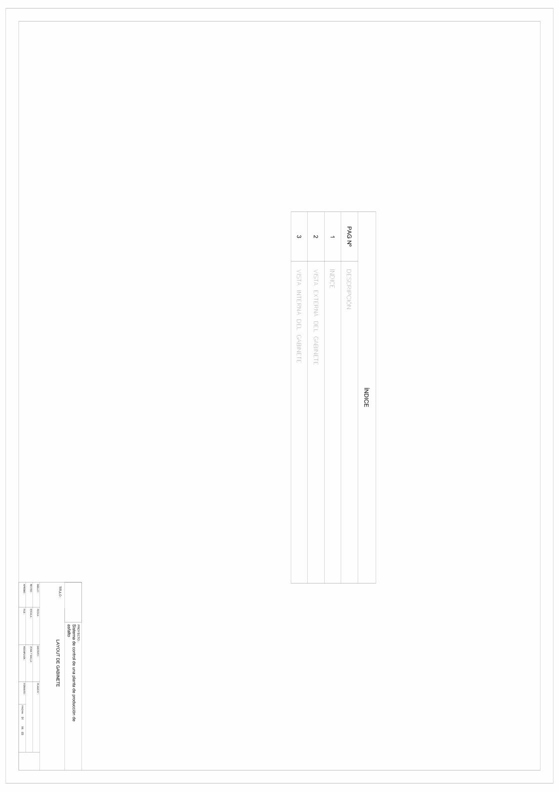

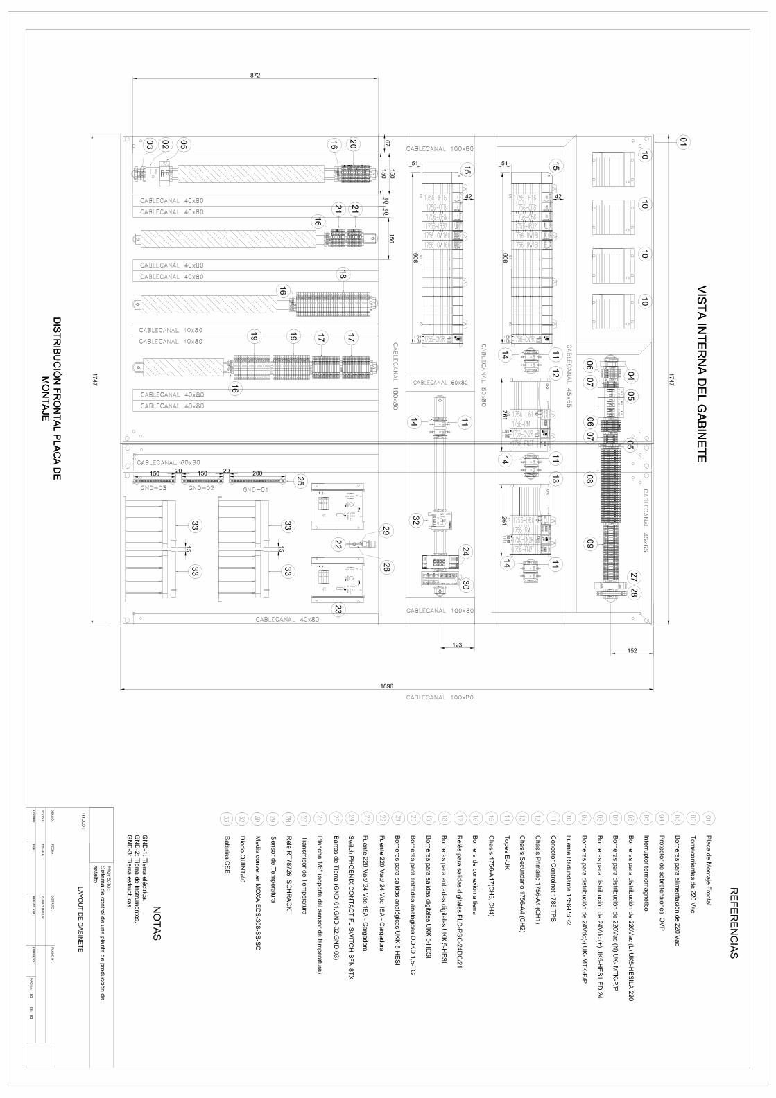

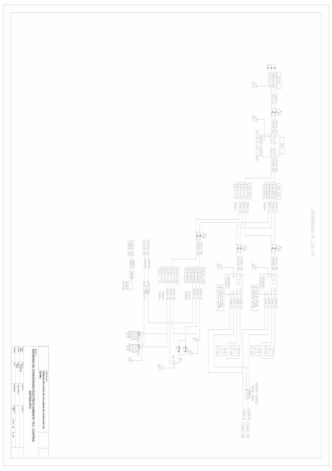

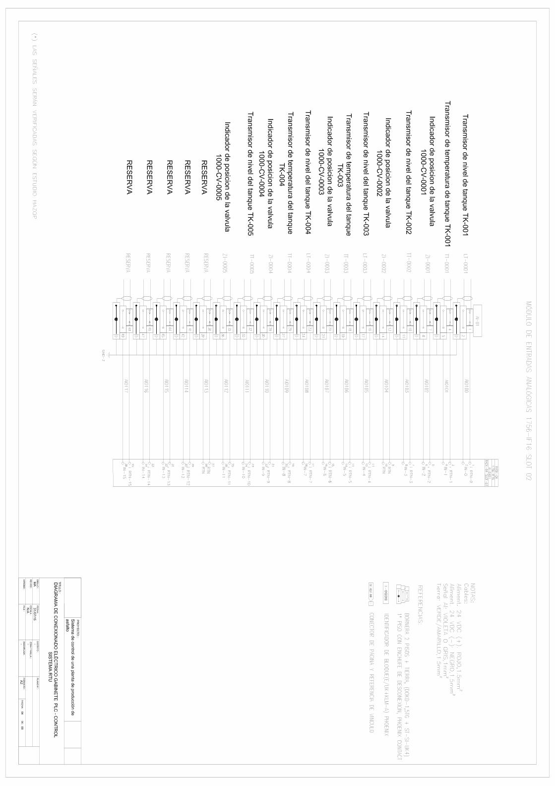

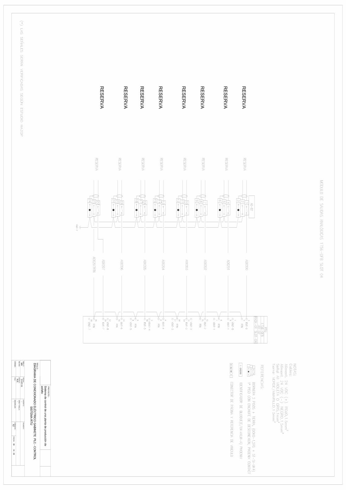
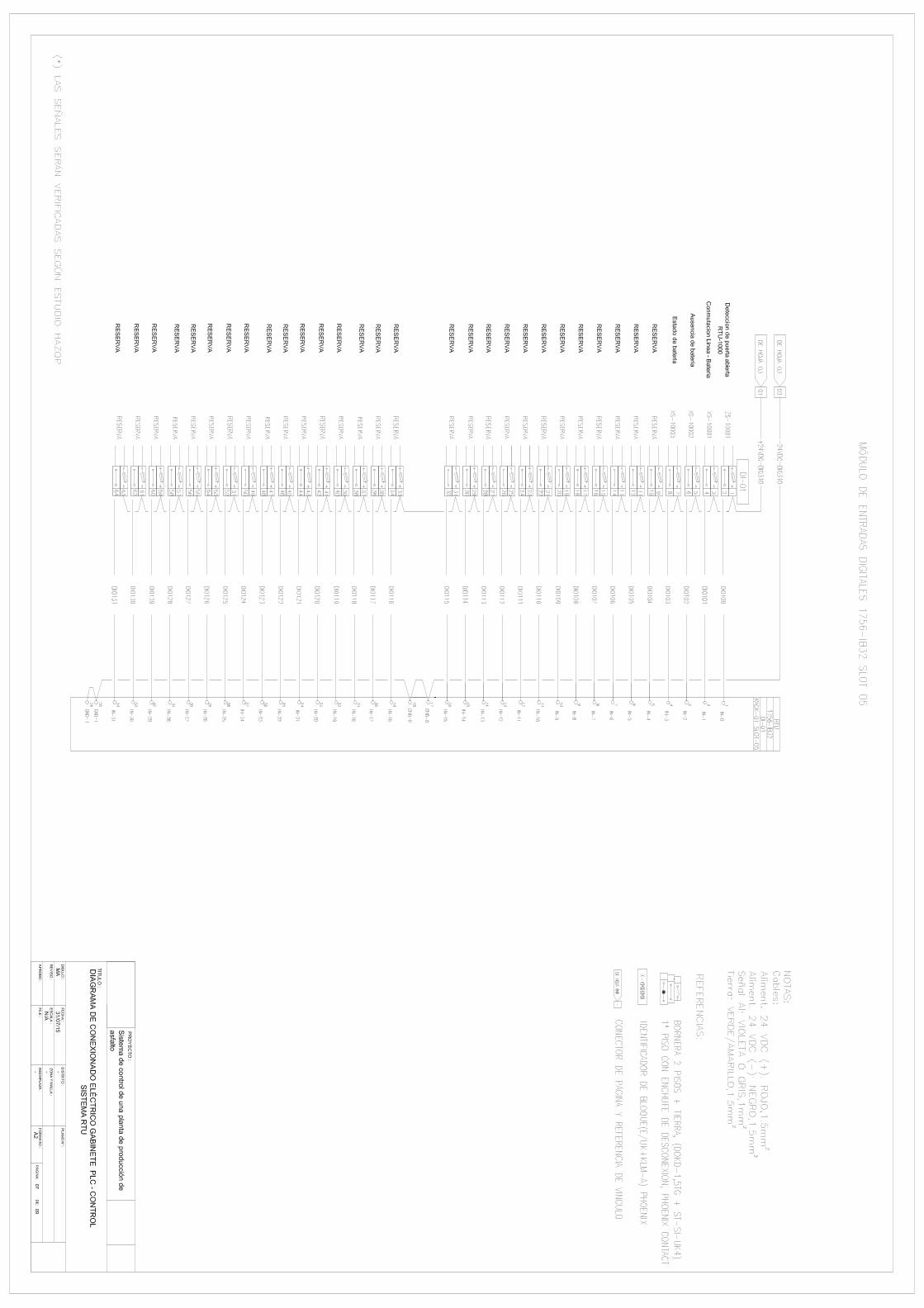
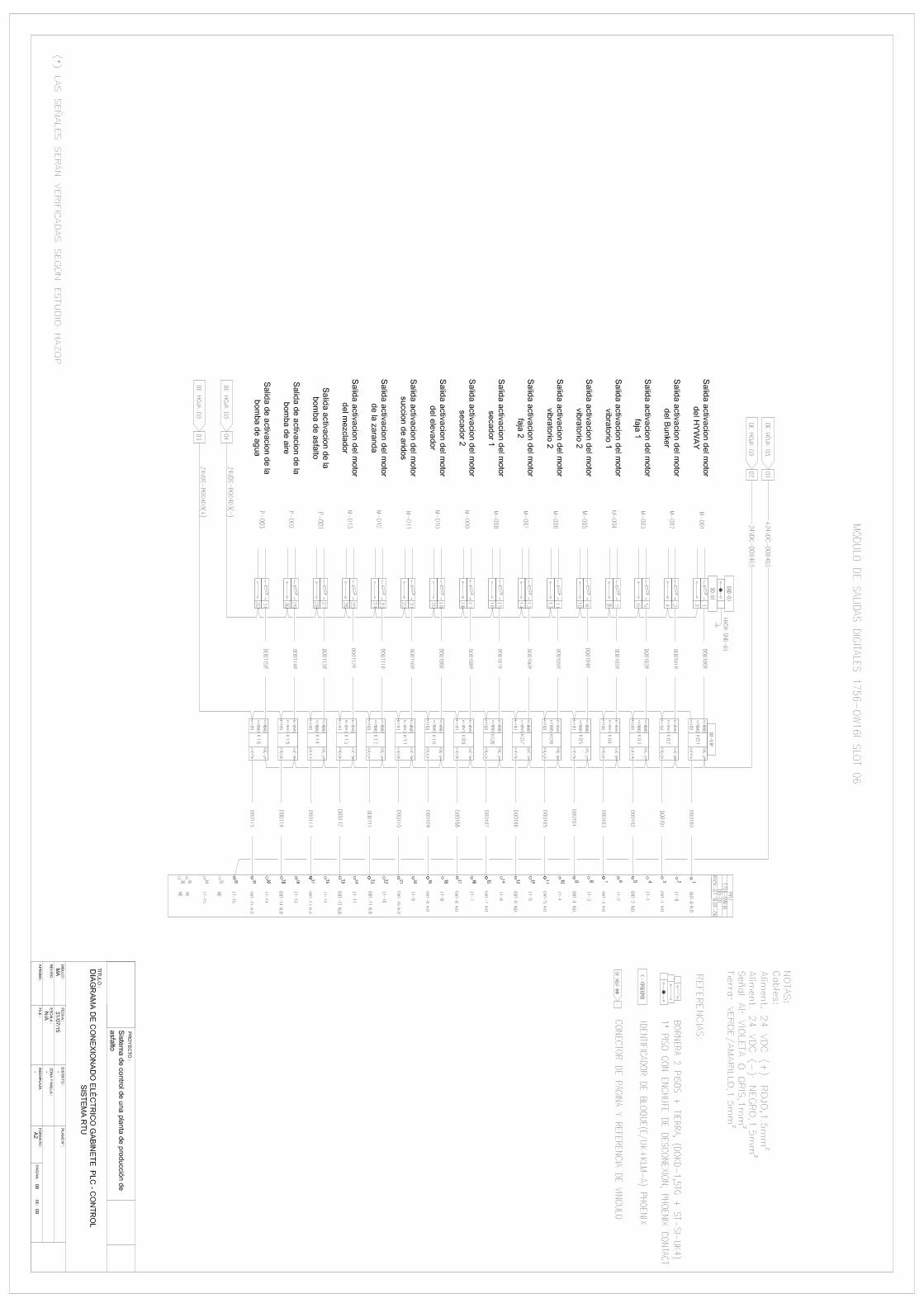

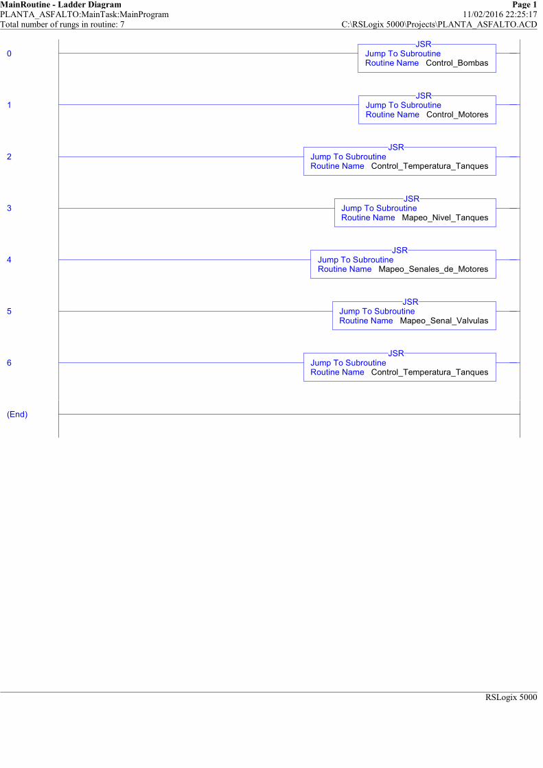
MainRoutine - Ladder Diagram Page 1PLANTA_ASFALTO:MainTask:MainProgram 11/02/2016 22:25:17Total number of rungs in routine: 7 C:\RSLogix 5000\Projects\PLANTA_ASFALTO.ACD
RSLogix 5000
0 Jump To SubroutineRoutine Name Control_Bombas
JSR
1 Jump To SubroutineRoutine Name Control_Motores
JSR
2 Jump To SubroutineRoutine Name Control_Temperatura_Tanques
JSR
3 Jump To SubroutineRoutine Name Mapeo_Nivel_Tanques
JSR
4 Jump To SubroutineRoutine Name Mapeo_Senales_de_Motores
JSR
5 Jump To SubroutineRoutine Name Mapeo_Senal_Valvulas
JSR
6 Jump To SubroutineRoutine Name Control_Temperatura_Tanques
JSR
(End)
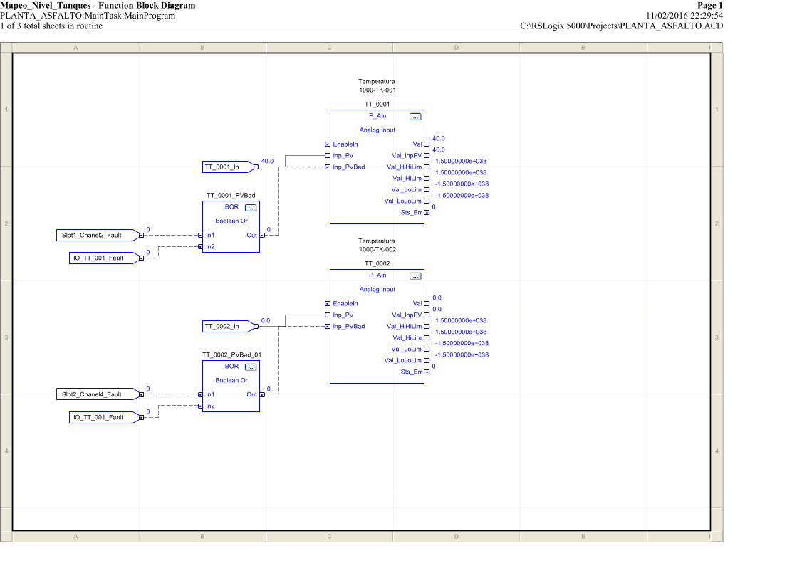
Mapeo_Nivel_Tanques - Function Block Diagram Page 1PLANTA_ASFALTO:MainTask:MainProgram 11/02/2016 22:29:541 of 3 total sheets in routine C:\RSLogix 5000\Projects\PLANTA_ASFALTO.ACD
A B C D E F
1
2
3
4
A B C D E F
1
2
3
4
Slot2_Chanel4_Fault0
TT_0001_PVBad
BOR ...
Boolean Or
In1
In2
Out0
Temperatura
1000-TK-002
TT_0002
P_AIn ...
Analog Input
EnableIn
Inp_PV
Inp_PVBad
Val0.0
Val_InpPV0.0
Val_HiHiLim1.50000000e+038
Val_HiLim1.50000000e+038
Val_LoLim-1.50000000e+038
Val_LoLoLim-1.50000000e+038
Sts_Err0
IO_TT_001_Fault0
Slot1_Chanel2_Fault0
IO_TT_001_Fault0
TT_0002_PVBad_01
BOR ...
Boolean Or
In1
In2
Out0
Temperatura
1000-TK-001
TT_0001
P_AIn ...
Analog Input
EnableIn
Inp_PV
Inp_PVBad
Val40.0
Val_InpPV40.0
Val_HiHiLim1.50000000e+038
Val_HiLim1.50000000e+038
Val_LoLim-1.50000000e+038
Val_LoLoLim-1.50000000e+038
Sts_Err0
TT_0001_In40.0
TT_0002_In0.0
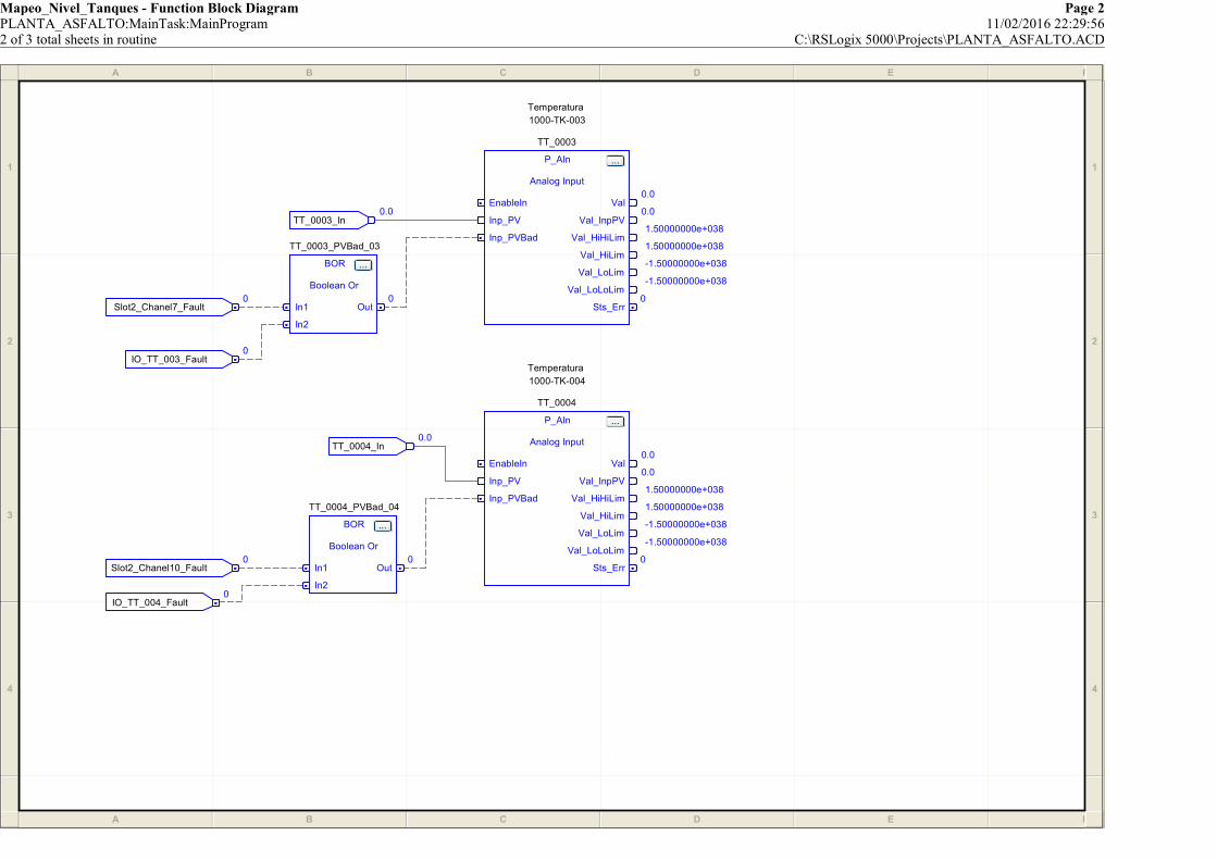
Mapeo_Nivel_Tanques - Function Block Diagram Page 2PLANTA_ASFALTO:MainTask:MainProgram 11/02/2016 22:29:562 of 3 total sheets in routine C:\RSLogix 5000\Projects\PLANTA_ASFALTO.ACD
A B C D E F
1
2
3
4
A B C D E F
1
2
3
4
TT_0003_PVBad_03
BOR ...
Boolean Or
In1
In2
Out0
IO_TT_003_Fault0
TT_0004_PVBad_04
BOR ...
Boolean Or
In1
In2
Out0
TT_0003_In0.0
IO_TT_004_Fault0
Slot2_Chanel7_Fault0
TT_0004_In0.0
Temperatura
1000-TK-003
TT_0003
P_AIn ...
Analog Input
EnableIn
Inp_PV
Inp_PVBad
Val0.0
Val_InpPV0.0
Val_HiHiLim1.50000000e+038
Val_HiLim1.50000000e+038
Val_LoLim-1.50000000e+038
Val_LoLoLim-1.50000000e+038
Sts_Err0
Slot2_Chanel10_Fault0
Temperatura
1000-TK-004
TT_0004
P_AIn ...
Analog Input
EnableIn
Inp_PV
Inp_PVBad
Val0.0
Val_InpPV0.0
Val_HiHiLim1.50000000e+038
Val_HiLim1.50000000e+038
Val_LoLim-1.50000000e+038
Val_LoLoLim-1.50000000e+038
Sts_Err0
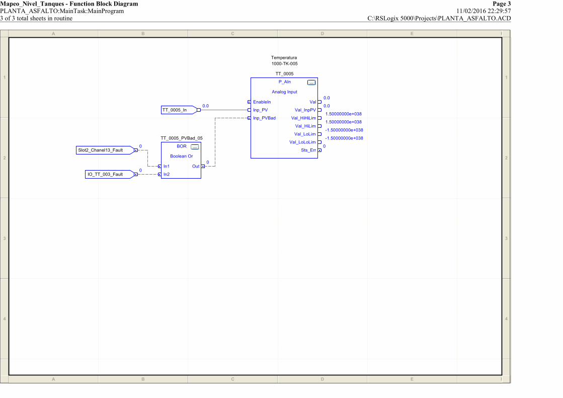
Mapeo_Nivel_Tanques - Function Block Diagram Page 3PLANTA_ASFALTO:MainTask:MainProgram 11/02/2016 22:29:573 of 3 total sheets in routine C:\RSLogix 5000\Projects\PLANTA_ASFALTO.ACD
A B C D E F
1
2
3
4
A B C D E F
1
2
3
4
TT_0005_PVBad_05
BOR ...
Boolean Or
In1
In2
Out0
IO_TT_003_Fault0
Temperatura
1000-TK-005
TT_0005
P_AIn ...
Analog Input
EnableIn
Inp_PV
Inp_PVBad
Val0.0
Val_InpPV0.0
Val_HiHiLim1.50000000e+038
Val_HiLim1.50000000e+038
Val_LoLim-1.50000000e+038
Val_LoLoLim-1.50000000e+038
Sts_Err0
Slot2_Chanel13_Fault0
TT_0005_In0.0

Mapeo_Senal_Valvulas - Function Block Diagram Page 1PLANTA_ASFALTO:MainTask:MainProgram 11/02/2016 22:30:311 of 3 total sheets in routine C:\RSLogix 5000\Projects\PLANTA_ASFALTO.ACD
A B C D E F
1
2
3
4
A B C D E F
1
2
3
4
Slot2_Chanel5_Fault0
Analog Input
ZI_0001
P_AIn ...
Analog Input
EnableIn
Inp_PV
Inp_PVBad
Val0.0
Val_InpPV0.0
Val_HiHiLim1.50000000e+038
Val_HiLim1.50000000e+038
Val_LoLim-1.50000000e+038
Val_LoLoLim-1.50000000e+038
Sts_Err0
Slot2_Chanel2_Fault0
ZI_0001_In0.0
ZI_0001_PVBad
BOR ...
Boolean Or
In1
In2
Out0
Analog Input
ZI_0002
P_AIn ...
Analog Input
EnableIn
Inp_PV
Inp_PVBad
Val0.0
Val_InpPV0.0
Val_HiHiLim1.50000000e+038
Val_HiLim1.50000000e+038
Val_LoLim-1.50000000e+038
Val_LoLoLim-1.50000000e+038
Sts_Err0
IO_ZI_002_Fault0
ZI_0002_PVBad_01
BOR ...
Boolean Or
In1
In2
Out0
IO_ZI_001_Fault0
ZI_0002_In0.0
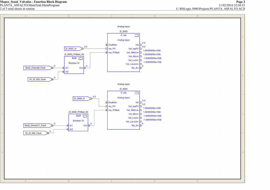
Mapeo_Senal_Valvulas - Function Block Diagram Page 2PLANTA_ASFALTO:MainTask:MainProgram 11/02/2016 22:30:332 of 3 total sheets in routine C:\RSLogix 5000\Projects\PLANTA_ASFALTO.ACD
A B C D E F
1
2
3
4
A B C D E F
1
2
3
4
ZI_0003_In0.0
Analog Input
ZI_0004
P_AIn ...
Analog Input
EnableIn
Inp_PV
Inp_PVBad
Val0.0
Val_InpPV0.0
Val_HiHiLim1.50000000e+038
Val_HiLim1.50000000e+038
Val_LoLim-1.50000000e+038
Val_LoLoLim-1.50000000e+038
Sts_Err0
ZI_0004_PVBad_04
BOR ...
Boolean Or
In1
In2
Out0
Slot2_Chanel11_Fault0
IO_ZI_004_Fault0
Slot2_Chanel8_Fault0
ZI_0003_PVBad_03
BOR ...
Boolean Or
In1
In2
Out0
IO_ZI_003_Fault0
ZI_0004_In0.0
Analog Input
ZI_0003
P_AIn ...
Analog Input
EnableIn
Inp_PV
Inp_PVBad
Val0.0
Val_InpPV0.0
Val_HiHiLim1.50000000e+038
Val_HiLim1.50000000e+038
Val_LoLim-1.50000000e+038
Val_LoLoLim-1.50000000e+038
Sts_Err0
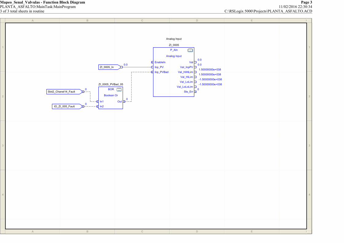
Mapeo_Senal_Valvulas - Function Block Diagram Page 3PLANTA_ASFALTO:MainTask:MainProgram 11/02/2016 22:30:343 of 3 total sheets in routine C:\RSLogix 5000\Projects\PLANTA_ASFALTO.ACD
A B C D E F
1
2
3
4
A B C D E F
1
2
3
4
ZI_0005_PVBad_05
BOR ...
Boolean Or
In1
In2
Out0
ZI_0005_In0.0
Slot2_Chanel14_Fault0
IO_ZI_005_Fault0
Analog Input
ZI_0005
P_AIn ...
Analog Input
EnableIn
Inp_PV
Inp_PVBad
Val0.0
Val_InpPV0.0
Val_HiHiLim1.50000000e+038
Val_HiLim1.50000000e+038
Val_LoLim-1.50000000e+038
Val_LoLoLim-1.50000000e+038
Sts_Err0
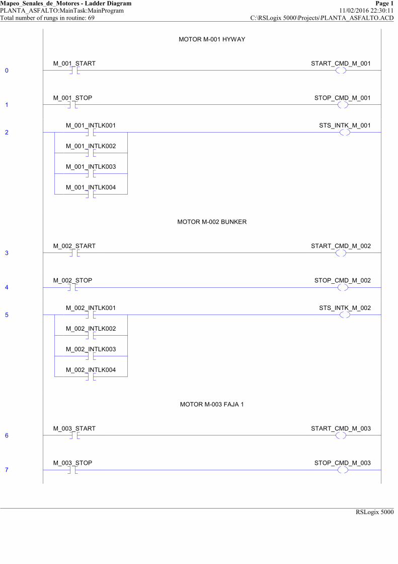
Mapeo_Senales_de_Motores - Ladder Diagram Page 1PLANTA_ASFALTO:MainTask:MainProgram 11/02/2016 22:30:11Total number of rungs in routine: 69 C:\RSLogix 5000\Projects\PLANTA_ASFALTO.ACD
RSLogix 5000
MOTOR M-001 HYWAY
0M_001_START START_CMD_M_001
MOTOR M-001 HYWAY
1M_001_STOP STOP_CMD_M_001
2M_001_INTLK001
M_001_INTLK002
M_001_INTLK003
M_001_INTLK004
STS_INTK_M_001
MOTOR M-002 BUNKER
3M_002_START START_CMD_M_002
MOTOR M-002 BUNKER
4M_002_STOP STOP_CMD_M_002
5M_002_INTLK001
M_002_INTLK002
M_002_INTLK003
M_002_INTLK004
STS_INTK_M_002
MOTOR M-003 FAJA 1
6M_003_START START_CMD_M_003
MOTOR M-003 FAJA 1
7M_003_STOP STOP_CMD_M_003

Mapeo_Senales_de_Motores - Ladder Diagram Page 2PLANTA_ASFALTO:MainTask:MainProgram 11/02/2016 22:30:12Total number of rungs in routine: 69 C:\RSLogix 5000\Projects\PLANTA_ASFALTO.ACD
RSLogix 5000
8M_003_INTLK001
M_003_INTLK002
M_003_INTLK003
M_003_INTLK004
STS_INTK_M_003
MOTOR M-004 MOTOR VIBRATORIO 1
9M_004_START START_CMD_M_004
MOTOR M-004 MOTOR VIBRATORIO 1
10M_004_STOP STOP_CMD_M_004
11M_004_INTLK001
M_004_INTLK002
M_004_INTLK003
M_004_INTLK004
STS_INTK_M_004
MOTOR M-005 MOTOR VIBRATORIO 2
12M_005_START START_CMD_M_005
MOTOR M-005 MOTOR VIBRATORIO 2
13M_005_STOP STOP_CMD_M_005
14M_005_INTLK001
M_005_INTLK002
M_005_INTLK003
M_005_INTLK004
STS_INTK_M_005
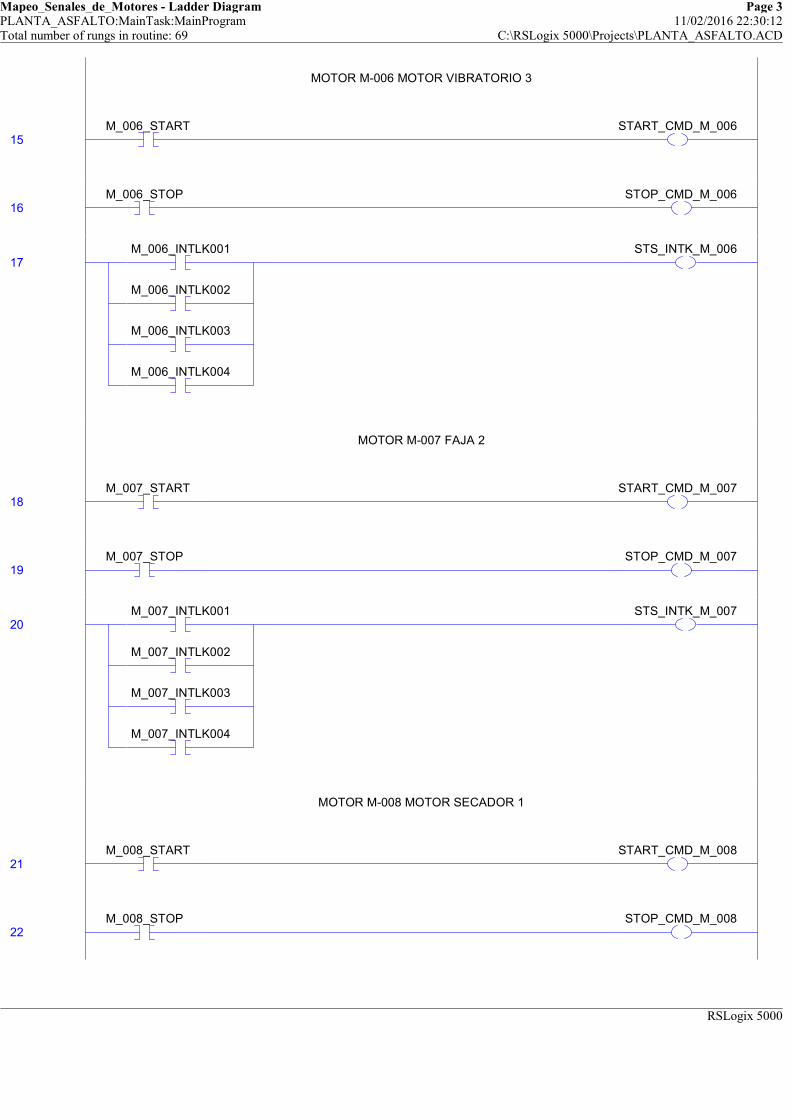
Mapeo_Senales_de_Motores - Ladder Diagram Page 3PLANTA_ASFALTO:MainTask:MainProgram 11/02/2016 22:30:12Total number of rungs in routine: 69 C:\RSLogix 5000\Projects\PLANTA_ASFALTO.ACD
RSLogix 5000
MOTOR M-006 MOTOR VIBRATORIO 3
15M_006_START START_CMD_M_006
MOTOR M-006 MOTOR VIBRATORIO 3
16M_006_STOP STOP_CMD_M_006
17M_006_INTLK001
M_006_INTLK002
M_006_INTLK003
M_006_INTLK004
STS_INTK_M_006
MOTOR M-007 FAJA 2
18M_007_START START_CMD_M_007
MOTOR M-007 FAJA 2
19M_007_STOP STOP_CMD_M_007
20M_007_INTLK001
M_007_INTLK002
M_007_INTLK003
M_007_INTLK004
STS_INTK_M_007
MOTOR M-008 MOTOR SECADOR 1
21M_008_START START_CMD_M_008
MOTOR M-008 MOTOR SECADOR 1
22M_008_STOP STOP_CMD_M_008

Mapeo_Senales_de_Motores - Ladder Diagram Page 4PLANTA_ASFALTO:MainTask:MainProgram 11/02/2016 22:30:12Total number of rungs in routine: 69 C:\RSLogix 5000\Projects\PLANTA_ASFALTO.ACD
RSLogix 5000
23M_008_INTLK001
M_008_INTLK002
M_008_INTLK003
M_008_INTLK004
STS_INTK_M_008
MOTOR M-009 MOTOR SECADOR 2
24M_009_START START_CMD_M_009
MOTOR M-009 MOTOR SECADOR 2
25M_009_STOP STOP_CMD_M_009
26M_009_INTLK001
M_009_INTLK002
M_009_INTLK003
M_009_INTLK004
STS_INTK_M_009
MOTOR M-010 ELEVADOR
27M_010_START START_CMD_M_010
MOTOR M-010 ELEVADOR
28M_010_STOP STOP_CMD_M_010
29M_010_INTLK001
M_010_INTLK002
M_010_INTLK003
M_010_INTLK004
STS_INTK_M_010

Mapeo_Senales_de_Motores - Ladder Diagram Page 5PLANTA_ASFALTO:MainTask:MainProgram 11/02/2016 22:30:12Total number of rungs in routine: 69 C:\RSLogix 5000\Projects\PLANTA_ASFALTO.ACD
RSLogix 5000
MOTOR M-011MOTOR SUCCION ARIDOS
30M_011_START START_CMD_M_011
MOTOR M-011MOTOR SUCCION ARIDOS
31M_011_STOP STOP_CMD_M_011
32M_011_INTLK001
M_011_INTLK002
M_011_INTLK003
M_011_INTLK004
STS_INTK_M_011
MOTOR M-012 ZARANDA
33M_012_START START_CMD_M_012
MOTOR M-012 ZARANDA
34M_012_STOP STOP_CMD_M_012
35M_012_INTLK001
M_012_INTLK002
M_012_INTLK003
M_012_INTLK004
STS_INTK_M_012
MOTOR M-013 MEZCLADOR
36M_013_START START_CMD_M_013
MOTOR M-013 MEZCLADOR
37M_013_STOP STOP_CMD_M_013

Mapeo_Senales_de_Motores - Ladder Diagram Page 6PLANTA_ASFALTO:MainTask:MainProgram 11/02/2016 22:30:13Total number of rungs in routine: 69 C:\RSLogix 5000\Projects\PLANTA_ASFALTO.ACD
RSLogix 5000
38M_013_INTLK001
M_013_INTLK002
M_013_INTLK003
M_013_INTLK004
STS_INTK_M_013
MOTOR M-001 HYWAY
39M_001_START START_CMD_M_001
MOTOR M-001 HYWAY
40M_001_STOP STOP_CMD_M_001
41M_001_INTLK001
M_001_INTLK002
M_001_INTLK003
M_001_INTLK004
STS_INTK_M_001
MOTOR M-001 HYWAY
42M_001_START START_CMD_M_001
MOTOR M-001 HYWAY
43M_001_STOP STOP_CMD_M_001
44M_001_INTLK001
M_001_INTLK002
M_001_INTLK003
M_001_INTLK004
STS_INTK_M_001

Mapeo_Senales_de_Motores - Ladder Diagram Page 7PLANTA_ASFALTO:MainTask:MainProgram 11/02/2016 22:30:13Total number of rungs in routine: 69 C:\RSLogix 5000\Projects\PLANTA_ASFALTO.ACD
RSLogix 5000
MOTOR M-001 HYWAY
45M_001_START START_CMD_M_001
MOTOR M-001 HYWAY
46M_001_STOP STOP_CMD_M_001
47M_001_INTLK001
M_001_INTLK002
M_001_INTLK003
M_001_INTLK004
STS_INTK_M_001
MOTOR M-001 HYWAY
48M_001_START START_CMD_M_001
MOTOR M-001 HYWAY
49M_001_STOP STOP_CMD_M_001
50M_001_INTLK001
M_001_INTLK002
M_001_INTLK003
M_001_INTLK004
STS_INTK_M_001
MOTOR M-001 HYWAY
51M_001_START START_CMD_M_001
MOTOR M-001 HYWAY
52M_001_STOP STOP_CMD_M_001
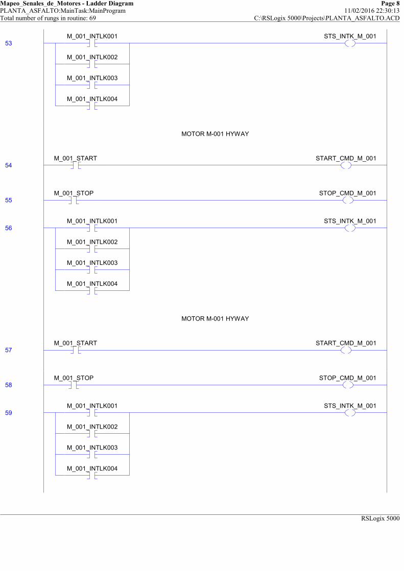
Mapeo_Senales_de_Motores - Ladder Diagram Page 8PLANTA_ASFALTO:MainTask:MainProgram 11/02/2016 22:30:13Total number of rungs in routine: 69 C:\RSLogix 5000\Projects\PLANTA_ASFALTO.ACD
RSLogix 5000
53M_001_INTLK001
M_001_INTLK002
M_001_INTLK003
M_001_INTLK004
STS_INTK_M_001
MOTOR M-001 HYWAY
54M_001_START START_CMD_M_001
MOTOR M-001 HYWAY
55M_001_STOP STOP_CMD_M_001
56M_001_INTLK001
M_001_INTLK002
M_001_INTLK003
M_001_INTLK004
STS_INTK_M_001
MOTOR M-001 HYWAY
57M_001_START START_CMD_M_001
MOTOR M-001 HYWAY
58M_001_STOP STOP_CMD_M_001
59M_001_INTLK001
M_001_INTLK002
M_001_INTLK003
M_001_INTLK004
STS_INTK_M_001
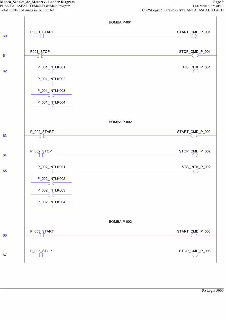
Mapeo_Senales_de_Motores - Ladder Diagram Page 9PLANTA_ASFALTO:MainTask:MainProgram 11/02/2016 22:30:13Total number of rungs in routine: 69 C:\RSLogix 5000\Projects\PLANTA_ASFALTO.ACD
RSLogix 5000
BOMBA P-001
60P_001_START START_CMD_P_001
BOMBA P-001
61P001_STOP STOP_CMD_P_001
62P_001_INTLK001
P_001_INTLK002
P_001_INTLK003
P_001_INTLK004
STS_INTK_P_001
BOMBA P-002
63P_002_START START_CMD_P_002
BOMBA P-002
64P_002_STOP STOP_CMD_P_002
65P_002_INTLK001
P_002_INTLK002
P_002_INTLK003
P_002_INTLK004
STS_INTK_P_002
BOMBA P-003
66P_003_START START_CMD_P_003
BOMBA P-003
67P_003_STOP STOP_CMD_P_003
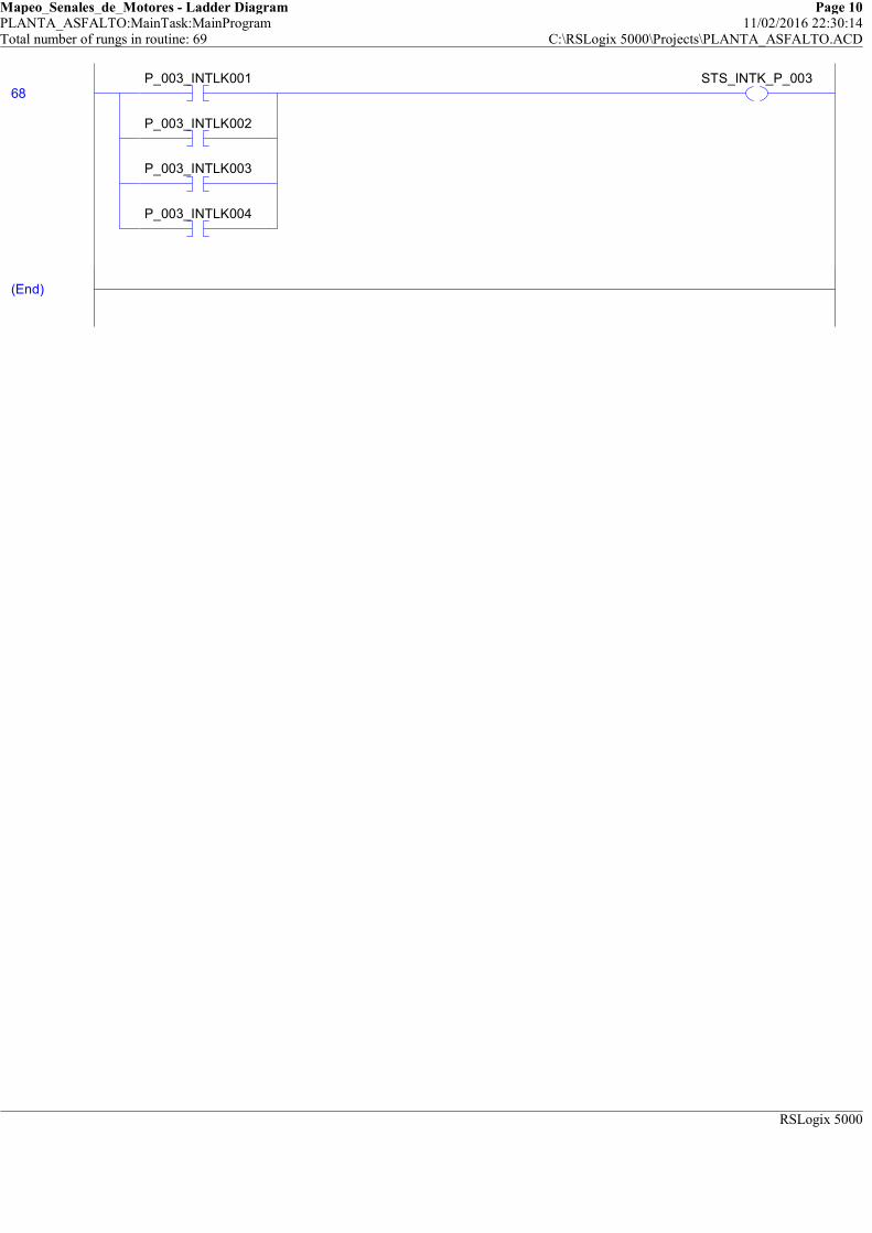
Mapeo_Senales_de_Motores - Ladder Diagram Page 10PLANTA_ASFALTO:MainTask:MainProgram 11/02/2016 22:30:14Total number of rungs in routine: 69 C:\RSLogix 5000\Projects\PLANTA_ASFALTO.ACD
RSLogix 5000
68P_003_INTLK001
P_003_INTLK002
P_003_INTLK003
P_003_INTLK004
STS_INTK_P_003
(End)

Mapeo_Temperatura_Tanques - Function Block Diagram Page 1PLANTA_ASFALTO:MainTask:MainProgram 11/02/2016 22:30:511 of 3 total sheets in routine C:\RSLogix 5000\Projects\PLANTA_ASFALTO.ACD
A B C D E F
1
2
3
4
A B C D E F
1
2
3
4
LT_0001_In0.0
LT_0002_PVBad_01
BOR ...
Boolean Or
In1
In2
Out0
Analog Input
LT_0002
P_AIn ...
Analog Input
EnableIn
Inp_PV
Inp_PVBad
Val0.0
Val_InpPV0.0
Val_HiHiLim1.50000000e+038
Val_HiLim1.50000000e+038
Val_LoLim-1.50000000e+038
Val_LoLoLim-1.50000000e+038
Sts_Err0
Slot2_Chanel2_Fault0
LT_0002_In0.0
IO_LT_001_Fault0
Analog Input
LT_0001
P_AIn ...
Analog Input
EnableIn
Inp_PV
Inp_PVBad
Val0.0
Val_InpPV0.0
Val_HiHiLim1.50000000e+038
Val_HiLim1.50000000e+038
Val_LoLim-1.50000000e+038
Val_LoLoLim-1.50000000e+038
Sts_Err0
IO_LT_001_Fault0
Slot2_Chanel0_Fault0
LT_0001_PVBad
BOR ...
Boolean Or
In1
In2
Out0

Mapeo_Temperatura_Tanques - Function Block Diagram Page 2PLANTA_ASFALTO:MainTask:MainProgram 11/02/2016 22:30:582 of 3 total sheets in routine C:\RSLogix 5000\Projects\PLANTA_ASFALTO.ACD
A B C D E F
1
2
3
4
A B C D E F
1
2
3
4
Slot2_Chanel6_Fault0
Analog Input
LT_0003
P_AIn ...
Analog Input
EnableIn
Inp_PV
Inp_PVBad
Val0.0
Val_InpPV0.0
Val_HiHiLim1.50000000e+038
Val_HiLim1.50000000e+038
Val_LoLim-1.50000000e+038
Val_LoLoLim-1.50000000e+038
Sts_Err0
Slot2_Chanel9_Fault0
LT_0004_In0.0
LT_0004_PVBad_04
BOR ...
Boolean Or
In1
In2
Out0
LT_0003_In0.0
LT_0003_PVBad_03
BOR ...
Boolean Or
In1
In2
Out0
IO_LT_003_Fault0
IO_LT_004_Fault0
Analog Input
LT_0004
P_AIn ...
Analog Input
EnableIn
Inp_PV
Inp_PVBad
Val0.0
Val_InpPV0.0
Val_HiHiLim1.50000000e+038
Val_HiLim1.50000000e+038
Val_LoLim-1.50000000e+038
Val_LoLoLim-1.50000000e+038
Sts_Err0

Mapeo_Temperatura_Tanques - Function Block Diagram Page 3PLANTA_ASFALTO:MainTask:MainProgram 11/02/2016 22:30:593 of 3 total sheets in routine C:\RSLogix 5000\Projects\PLANTA_ASFALTO.ACD
A B C D E F
1
2
3
4
A B C D E F
1
2
3
4
LT_0005_PVBad_05
BOR ...
Boolean Or
In1
In2
Out0
Slot2_Chanel12_Fault0
IO_LT_005_Fault0
Analog Input
LT_0005
P_AIn ...
Analog Input
EnableIn
Inp_PV
Inp_PVBad
Val0.0
Val_InpPV0.0
Val_HiHiLim1.50000000e+038
Val_HiLim1.50000000e+038
Val_LoLim-1.50000000e+038
Val_LoLoLim-1.50000000e+038
Sts_Err0
LT_0005_In0.0

Control_Temperatura_Tanques - Function Block Diagram Page 1PLANTA_ASFALTO:MainTask:MainProgram 11/02/2016 22:29:321 of 3 total sheets in routine C:\RSLogix 5000\Projects\PLANTA_ASFALTO.ACD
A B C D E F
1
2
3
4
A B C D E F
1
2
3
4
Lazo de Control de
Temperatura
1000-TK-0001
PID_0001
PIDE ...
Enhanced PID
PV
SPProg
SPCascade
CVProg
ProgProgReq
ProgOperReq
ProgCasRatReq
ProgAutoReq
ProgManualReq
ProgOverrideReq
ProgHandReq
CVEU0.0
SP0.0
PVHHAlarm0
PVHAlarm0
PVLAlarm0
PVLLAlarm0
ProgOper0
Auto0
Manual1
Override0
Hand0
AutotuneTag PID_0001_Autotune
SETPOINT_CV_00010.0
CV_0001_OUT
CV_0002_OUT
Salida Valvula
CV-0001
CV_0001
P_AOut ...
Salida Valvula CV-0001
Inp_Tieback
Inp_IntlkOK
Inp_NBIntlkOK
Inp_Hand
Inp_Ovrd
Inp_OvrdCV
PSet_CV
Out_CV0.0
Val_CVSet0.0
Val_CVOut0.0
Val_CVRoCLim0.0
Sts_Err0
Sts_Hand0
Sts_Maint0
Sts_Ovrd0
Sts_Prog0
Sts_Oper1
SETPOINT_CV_00020.0
Salida Valvula
CV-0002
CV_0002
P_AOut ...
Salida Valvula CV-0001
Inp_Tieback
Inp_IntlkOK
Inp_NBIntlkOK
Inp_Hand
Inp_Ovrd
Inp_OvrdCV
PSet_CV
Out_CV0.0
Val_CVSet0.0
Val_CVOut0.0
Val_CVRoCLim0.0
Sts_Err0
Sts_Hand0
Sts_Maint0
Sts_Ovrd0
Sts_Prog0
Sts_Oper1
Lazo de Control de
Temperatura
1000-TK-0002
PID_0002
PIDE ...
Enhanced PID
PV
SPProg
SPCascade
CVProg
ProgProgReq
ProgOperReq
ProgCasRatReq
ProgAutoReq
ProgManualReq
ProgOverrideReq
ProgHandReq
CVEU0.0
SP0.0
PVHHAlarm0
PVHAlarm0
PVLAlarm0
PVLLAlarm0
ProgOper0
Auto0
Manual1
Override0
Hand0
AutotuneTag PID_0002_Autotune
Temperatura
1000-TK-002 Analog
Value (after
Substitute PV, if
used)
TT_0002.vAl0.0
Temperatura
1000-TK-001 Analog
Value (after
Substitute PV, if
used)
TT_0001.vAl40.0
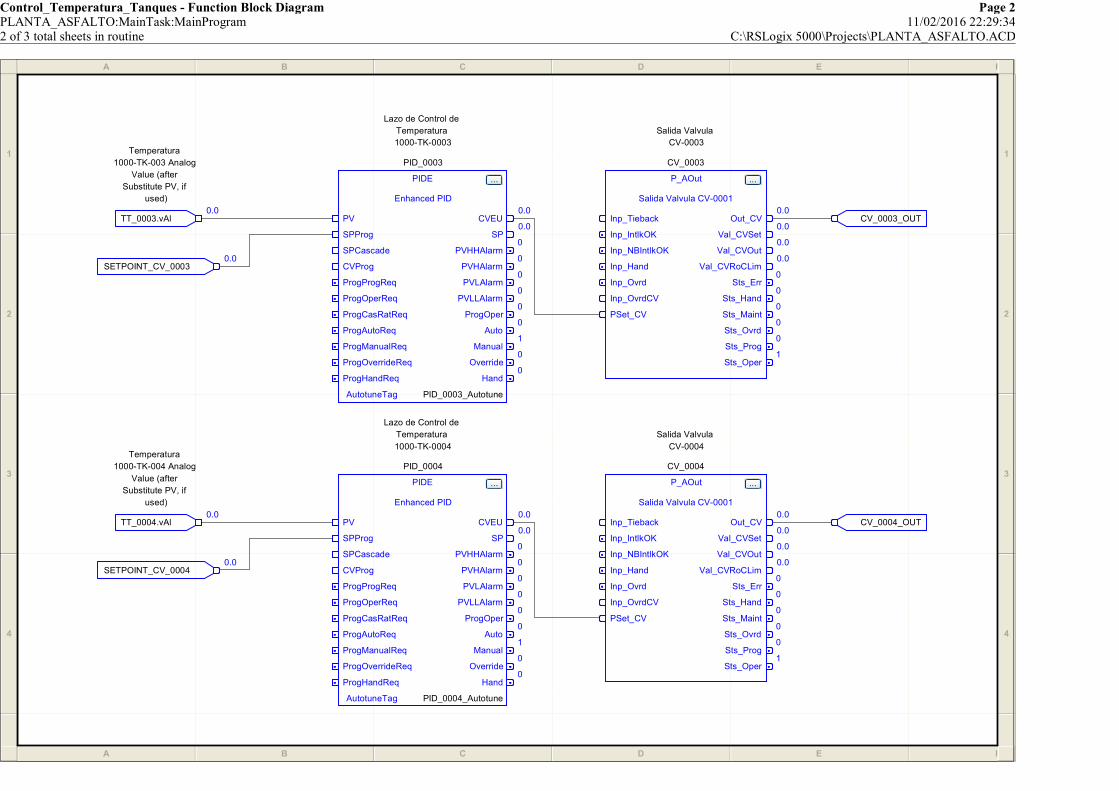
Control_Temperatura_Tanques - Function Block Diagram Page 2PLANTA_ASFALTO:MainTask:MainProgram 11/02/2016 22:29:342 of 3 total sheets in routine C:\RSLogix 5000\Projects\PLANTA_ASFALTO.ACD
A B C D E F
1
2
3
4
A B C D E F
1
2
3
4
SETPOINT_CV_00040.0
Lazo de Control de
Temperatura
1000-TK-0003
PID_0003
PIDE ...
Enhanced PID
PV
SPProg
SPCascade
CVProg
ProgProgReq
ProgOperReq
ProgCasRatReq
ProgAutoReq
ProgManualReq
ProgOverrideReq
ProgHandReq
CVEU0.0
SP0.0
PVHHAlarm0
PVHAlarm0
PVLAlarm0
PVLLAlarm0
ProgOper0
Auto0
Manual1
Override0
Hand0
AutotuneTag PID_0003_Autotune
Salida Valvula
CV-0004
CV_0004
P_AOut ...
Salida Valvula CV-0001
Inp_Tieback
Inp_IntlkOK
Inp_NBIntlkOK
Inp_Hand
Inp_Ovrd
Inp_OvrdCV
PSet_CV
Out_CV0.0
Val_CVSet0.0
Val_CVOut0.0
Val_CVRoCLim0.0
Sts_Err0
Sts_Hand0
Sts_Maint0
Sts_Ovrd0
Sts_Prog0
Sts_Oper1
Temperatura
1000-TK-004 Analog
Value (after
Substitute PV, if
used)
TT_0004.vAl0.0
SETPOINT_CV_00030.0
Lazo de Control de
Temperatura
1000-TK-0004
PID_0004
PIDE ...
Enhanced PID
PV
SPProg
SPCascade
CVProg
ProgProgReq
ProgOperReq
ProgCasRatReq
ProgAutoReq
ProgManualReq
ProgOverrideReq
ProgHandReq
CVEU0.0
SP0.0
PVHHAlarm0
PVHAlarm0
PVLAlarm0
PVLLAlarm0
ProgOper0
Auto0
Manual1
Override0
Hand0
AutotuneTag PID_0004_Autotune
Temperatura
1000-TK-003 Analog
Value (after
Substitute PV, if
used)
TT_0003.vAl0.0
Salida Valvula
CV-0003
CV_0003
P_AOut ...
Salida Valvula CV-0001
Inp_Tieback
Inp_IntlkOK
Inp_NBIntlkOK
Inp_Hand
Inp_Ovrd
Inp_OvrdCV
PSet_CV
Out_CV0.0
Val_CVSet0.0
Val_CVOut0.0
Val_CVRoCLim0.0
Sts_Err0
Sts_Hand0
Sts_Maint0
Sts_Ovrd0
Sts_Prog0
Sts_Oper1
CV_0004_OUT
CV_0003_OUT

Control_Temperatura_Tanques - Function Block Diagram Page 3PLANTA_ASFALTO:MainTask:MainProgram 11/02/2016 22:29:403 of 3 total sheets in routine C:\RSLogix 5000\Projects\PLANTA_ASFALTO.ACD
A B C D E F
1
2
3
4
A B C D E F
1
2
3
4
Temperatura
1000-TK-005 Analog
Value (after
Substitute PV, if
used)
TT_0005.vAl0.0
SETPOINT_CV_00050.0
CV_0005_OUT
Lazo de Control de
Temperatura
1000-TK-0005
PID_0005
PIDE ...
Enhanced PID
PV
SPProg
SPCascade
CVProg
ProgProgReq
ProgOperReq
ProgCasRatReq
ProgAutoReq
ProgManualReq
ProgOverrideReq
ProgHandReq
CVEU0.0
SP0.0
PVHHAlarm0
PVHAlarm0
PVLAlarm0
PVLLAlarm0
ProgOper0
Auto0
Manual1
Override0
Hand0
AutotuneTag PID_0005_Autotune
Salida Valvula
CV-0005
CV_0005
P_AOut ...
Salida Valvula CV-0001
Inp_Tieback
Inp_IntlkOK
Inp_NBIntlkOK
Inp_Hand
Inp_Ovrd
Inp_OvrdCV
PSet_CV
Out_CV0.0
Val_CVSet0.0
Val_CVOut0.0
Val_CVRoCLim0.0
Sts_Err0
Sts_Hand0
Sts_Maint0
Sts_Ovrd0
Sts_Prog0
Sts_Oper1
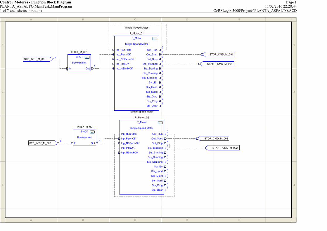
Control_Motores - Function Block Diagram Page 1PLANTA_ASFALTO:MainTask:MainProgram 11/02/2016 22:28:441 of 7 total sheets in routine C:\RSLogix 5000\Projects\PLANTA_ASFALTO.ACD
A B C D E F
1
2
3
4
A B C D E F
1
2
3
4
INTLK_M_02
BNOT ...
Boolean Not
In Out1
Single Speed Motor
P_Motor_01
P_Motor ...
Single Speed Motor
Inp_RunFdbk
Inp_PermOK
Inp_NBPermOK
Inp_IntlkOK
Inp_NBIntlkOK
Out_Run0
Out_Start0
Out_Stop0
Sts_Stopped1
Sts_Starting0
Sts_Running0
Sts_Stopping0
Sts_Err0
Sts_Hand0
Sts_Maint0
Sts_Ovrd0
Sts_Prog0
Sts_Oper1
STS_INTK_M_0010
INTLK_M_001
BNOT ...
Boolean Not
In Out1
START_CMD_M_001
START_CMD_M_002
STS_INTK_M_0020
STOP_CMD_M_002
STOP_CMD_M_001
Single Speed Motor
P_Motor_02
P_Motor ...
Single Speed Motor
Inp_RunFdbk
Inp_PermOK
Inp_NBPermOK
Inp_IntlkOK
Inp_NBIntlkOK
Out_Run0
Out_Start0
Out_Stop0
Sts_Stopped1
Sts_Starting0
Sts_Running0
Sts_Stopping0
Sts_Err0
Sts_Hand0
Sts_Maint0
Sts_Ovrd0
Sts_Prog0
Sts_Oper1

Control_Motores - Function Block Diagram Page 2PLANTA_ASFALTO:MainTask:MainProgram 11/02/2016 22:28:512 of 7 total sheets in routine C:\RSLogix 5000\Projects\PLANTA_ASFALTO.ACD
A B C D E F
1
2
3
4
A B C D E F
1
2
3
4
INTLK_M_03
BNOT ...
Boolean Not
In Out1
Single Speed Motor
P_Motor_04
P_Motor ...
Single Speed Motor
Inp_RunFdbk
Inp_PermOK
Inp_NBPermOK
Inp_IntlkOK
Inp_NBIntlkOK
Out_Run0
Out_Start0
Out_Stop0
Sts_Stopped1
Sts_Starting0
Sts_Running0
Sts_Stopping0
Sts_Err0
Sts_Hand0
Sts_Maint0
Sts_Ovrd0
Sts_Prog0
Sts_Oper1
START_CMD_M_004
STS_INTK_M_0030
Single Speed Motor
P_Motor_03
P_Motor ...
Single Speed Motor
Inp_RunFdbk
Inp_PermOK
Inp_NBPermOK
Inp_IntlkOK
Inp_NBIntlkOK
Out_Run0
Out_Start0
Out_Stop0
Sts_Stopped1
Sts_Starting0
Sts_Running0
Sts_Stopping0
Sts_Err0
Sts_Hand0
Sts_Maint0
Sts_Ovrd0
Sts_Prog0
Sts_Oper1
START_CMD_M_003
STOP_CMD_M_003
STOP_CMD_M_004
INTLK_M_04
BNOT ...
Boolean Not
In Out1
STS_INTK_M_0040

Control_Motores - Function Block Diagram Page 3PLANTA_ASFALTO:MainTask:MainProgram 11/02/2016 22:28:533 of 7 total sheets in routine C:\RSLogix 5000\Projects\PLANTA_ASFALTO.ACD
A B C D E F
1
2
3
4
A B C D E F
1
2
3
4
START_CMD_M_006
STOP_CMD_M_005
Single Speed Motor
P_Motor_05
P_Motor ...
Single Speed Motor
Inp_RunFdbk
Inp_PermOK
Inp_NBPermOK
Inp_IntlkOK
Inp_NBIntlkOK
Out_Run0
Out_Start0
Out_Stop0
Sts_Stopped1
Sts_Starting0
Sts_Running0
Sts_Stopping0
Sts_Err0
Sts_Hand0
Sts_Maint0
Sts_Ovrd0
Sts_Prog0
Sts_Oper1
STS_INTK_M_0060
INTLK_M_06
BNOT ...
Boolean Not
In Out1
STS_INTK_M_0050
INTLK_M_05
BNOT ...
Boolean Not
In Out1
START_CMD_M_005
STOP_CMD_M_006
Single Speed Motor
P_Motor_06
P_Motor ...
Single Speed Motor
Inp_RunFdbk
Inp_PermOK
Inp_NBPermOK
Inp_IntlkOK
Inp_NBIntlkOK
Out_Run0
Out_Start0
Out_Stop0
Sts_Stopped1
Sts_Starting0
Sts_Running0
Sts_Stopping0
Sts_Err0
Sts_Hand0
Sts_Maint0
Sts_Ovrd0
Sts_Prog0
Sts_Oper1
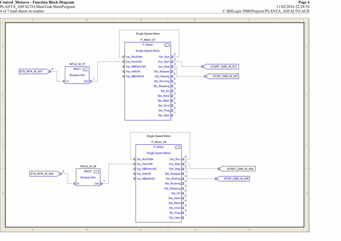
Control_Motores - Function Block Diagram Page 4PLANTA_ASFALTO:MainTask:MainProgram 11/02/2016 22:28:544 of 7 total sheets in routine C:\RSLogix 5000\Projects\PLANTA_ASFALTO.ACD
A B C D E F
1
2
3
4
A B C D E F
1
2
3
4
STS_INTK_M_0080
STOP_CMD_M_008
STS_INTK_M_0070
INTLK_M_08
BNOT ...
Boolean Not
In Out1
START_CMD_M_008
Single Speed Motor
P_Motor_08
P_Motor ...
Single Speed Motor
Inp_RunFdbk
Inp_PermOK
Inp_NBPermOK
Inp_IntlkOK
Inp_NBIntlkOK
Out_Run0
Out_Start0
Out_Stop0
Sts_Stopped1
Sts_Starting0
Sts_Running0
Sts_Stopping0
Sts_Err0
Sts_Hand0
Sts_Maint0
Sts_Ovrd0
Sts_Prog0
Sts_Oper1
Single Speed Motor
P_Motor_07
P_Motor ...
Single Speed Motor
Inp_RunFdbk
Inp_PermOK
Inp_NBPermOK
Inp_IntlkOK
Inp_NBIntlkOK
Out_Run0
Out_Start0
Out_Stop0
Sts_Stopped1
Sts_Starting0
Sts_Running0
Sts_Stopping0
Sts_Err0
Sts_Hand0
Sts_Maint0
Sts_Ovrd0
Sts_Prog0
Sts_Oper1
INTLK_M_07
BNOT ...
Boolean Not
In Out1
START_CMD_M_007
STOP_CMD_M_007

Control_Motores - Function Block Diagram Page 5PLANTA_ASFALTO:MainTask:MainProgram 11/02/2016 22:28:565 of 7 total sheets in routine C:\RSLogix 5000\Projects\PLANTA_ASFALTO.ACD
A B C D E F
1
2
3
4
A B C D E F
1
2
3
4
START_CMD_M_009
START_CMD_M_010
STS_INTK_M_0090
INTLK_M_09
BNOT ...
Boolean Not
In Out1
STOP_CMD_M_010
Single Speed Motor
P_Motor_09
P_Motor ...
Single Speed Motor
Inp_RunFdbk
Inp_PermOK
Inp_NBPermOK
Inp_IntlkOK
Inp_NBIntlkOK
Out_Run0
Out_Start0
Out_Stop0
Sts_Stopped1
Sts_Starting0
Sts_Running0
Sts_Stopping0
Sts_Err0
Sts_Hand0
Sts_Maint0
Sts_Ovrd0
Sts_Prog0
Sts_Oper1
INTLK_M_10
BNOT ...
Boolean Not
In Out1
STOP_CMD_M_009
Single Speed Motor
P_Motor_10
P_Motor ...
Single Speed Motor
Inp_RunFdbk
Inp_PermOK
Inp_NBPermOK
Inp_IntlkOK
Inp_NBIntlkOK
Out_Run0
Out_Start0
Out_Stop0
Sts_Stopped1
Sts_Starting0
Sts_Running0
Sts_Stopping0
Sts_Err0
Sts_Hand0
Sts_Maint0
Sts_Ovrd0
Sts_Prog0
Sts_Oper1
STS_INTK_M_0100

Control_Motores - Function Block Diagram Page 6PLANTA_ASFALTO:MainTask:MainProgram 11/02/2016 22:29:036 of 7 total sheets in routine C:\RSLogix 5000\Projects\PLANTA_ASFALTO.ACD
A B C D E F
1
2
3
4
A B C D E F
1
2
3
4
STS_INTK_M_0120
STS_INTK_M_0110
STOP_CMD_M_011
START_CMD_M_012
Single Speed Motor
P_Motor_12
P_Motor ...
Single Speed Motor
Inp_RunFdbk
Inp_PermOK
Inp_NBPermOK
Inp_IntlkOK
Inp_NBIntlkOK
Out_Run0
Out_Start0
Out_Stop0
Sts_Stopped1
Sts_Starting0
Sts_Running0
Sts_Stopping0
Sts_Err0
Sts_Hand0
Sts_Maint0
Sts_Ovrd0
Sts_Prog0
Sts_Oper1
INTLK_M_12
BNOT ...
Boolean Not
In Out1
START_CMD_M_011
Single Speed Motor
P_Motor_11
P_Motor ...
Single Speed Motor
Inp_RunFdbk
Inp_PermOK
Inp_NBPermOK
Inp_IntlkOK
Inp_NBIntlkOK
Out_Run0
Out_Start0
Out_Stop0
Sts_Stopped1
Sts_Starting0
Sts_Running0
Sts_Stopping0
Sts_Err0
Sts_Hand0
Sts_Maint0
Sts_Ovrd0
Sts_Prog0
Sts_Oper1
INTLK_M_11
BNOT ...
Boolean Not
In Out1
STOP_CMD_M_012

Control_Motores - Function Block Diagram Page 7PLANTA_ASFALTO:MainTask:MainProgram 11/02/2016 22:29:097 of 7 total sheets in routine C:\RSLogix 5000\Projects\PLANTA_ASFALTO.ACD
A B C D E F
1
2
3
4
A B C D E F
1
2
3
4
START_CMD_M_013
STS_INTK_M_0130
Single Speed Motor
P_Motor_13
P_Motor ...
Single Speed Motor
Inp_RunFdbk
Inp_PermOK
Inp_NBPermOK
Inp_IntlkOK
Inp_NBIntlkOK
Out_Run0
Out_Start0
Out_Stop0
Sts_Stopped1
Sts_Starting0
Sts_Running0
Sts_Stopping0
Sts_Err0
Sts_Hand0
Sts_Maint0
Sts_Ovrd0
Sts_Prog0
Sts_Oper1
STOP_CMD_M_013
INTLK_M_13
BNOT ...
Boolean Not
In Out1
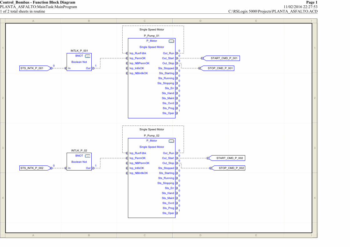
Control_Bombas - Function Block Diagram Page 1PLANTA_ASFALTO:MainTask:MainProgram 11/02/2016 22:27:531 of 2 total sheets in routine C:\RSLogix 5000\Projects\PLANTA_ASFALTO.ACD
A B C D E F
1
2
3
4
A B C D E F
1
2
3
4
STS_INTK_P_0010
START_CMD_P_001
STS_INTK_P_0020
INTLK_P_001
BNOT ...
Boolean Not
In Out1
Single Speed Motor
P_Pump_01
P_Motor ...
Single Speed Motor
Inp_RunFdbk
Inp_PermOK
Inp_NBPermOK
Inp_IntlkOK
Inp_NBIntlkOK
Out_Run0
Out_Start0
Out_Stop0
Sts_Stopped1
Sts_Starting0
Sts_Running0
Sts_Stopping0
Sts_Err0
Sts_Hand0
Sts_Maint0
Sts_Ovrd0
Sts_Prog0
Sts_Oper1
STOP_CMD_P_001
STOP_CMD_P_002
INTLK_P_02
BNOT ...
Boolean Not
In Out1
Single Speed Motor
P_Pump_02
P_Motor ...
Single Speed Motor
Inp_RunFdbk
Inp_PermOK
Inp_NBPermOK
Inp_IntlkOK
Inp_NBIntlkOK
Out_Run0
Out_Start0
Out_Stop0
Sts_Stopped1
Sts_Starting0
Sts_Running0
Sts_Stopping0
Sts_Err0
Sts_Hand0
Sts_Maint0
Sts_Ovrd0
Sts_Prog0
Sts_Oper1
START_CMD_P_002
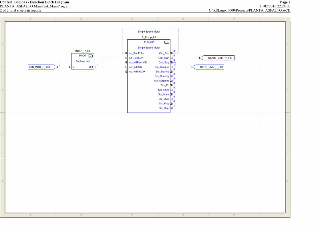
Control_Bombas - Function Block Diagram Page 2PLANTA_ASFALTO:MainTask:MainProgram 11/02/2016 22:28:002 of 2 total sheets in routine C:\RSLogix 5000\Projects\PLANTA_ASFALTO.ACD
A B C D E F
1
2
3
4
A B C D E F
1
2
3
4
STOP_CMD_P_003
INTLK_P_03
BNOT ...
Boolean Not
In Out1
Single Speed Motor
P_Pump_03
P_Motor ...
Single Speed Motor
Inp_RunFdbk
Inp_PermOK
Inp_NBPermOK
Inp_IntlkOK
Inp_NBIntlkOK
Out_Run0
Out_Start0
Out_Stop0
Sts_Stopped1
Sts_Starting0
Sts_Running0
Sts_Stopping0
Sts_Err0
Sts_Hand0
Sts_Maint0
Sts_Ovrd0
Sts_Prog0
Sts_Oper1
START_CMD_P_003
STS_INTK_P_0030

Logic - Ladder Diagram Page 1PLANTA_ASFALTO:Add-On Instructions:P_AIn 11/02/2016 22:31:30Total number of rungs in routine: 63 C:\RSLogix 5000\Projects\PLANTA_ASFALTO.ACDData Context: P_AIn <definition>
RSLogix 5000
============================================================P_AIn: PROCESS -- ANALOG INPUT
============================================================Revision 1.1-00 - Release: 2010-03-18
* (43, 6) Added Rdy_OSet for HMI to animate data entry fields* (54) Includes updated P_Alarm 1.1-00
* Fixed Err_Raw, Err_EU logic============================================================
This Instruction monitors an Analog Input from a flow, level, pressure,temperature, or any other analog sensor, and provides:
* Scaling, from Input (Raw) to PV (Engineering) Units* High-High, High, Low and Low-Low Alarms with configurable delay times and deadbands
* Monitoring of input bad/uncertain variable/communication status and out-of-range conditions with alarm* Setting of a simulated input signal for process simulation
Modes of operation: Operator, Program, Maintenance
* Program and Operator Settings for Alarm Thresholds* Maintenance Commands to allow manual override of the input signal (Substitute PV)
============================================================POWERUP / INVALID STATE HANDLING
============================================================See Prescan routine for powerup code required for this object.
============================================================MODE PROCESSING
============================================================These rungs handle received Mode Inputs and Commands:
NOTE: Operator Commands for Mode, Alarm are sent directly to the contained P_Mode and P_Alarm AOIs.
PCmd_Acq: Program Command to Acquire ownership
0
Program Command to Acquire ownership
(Oper to Prog)PCmd_Acq
1=Clear Program Commands on receipt
0=Leave SetCfg_PCmdClear
U
Program Command to Acquire ownership
(Oper to Prog)PCmd_Acq
L
Analog Input Mode Selection Program
Command to Acquire Ownership (Oper to
Prog)Mode.PCmd_Acq
/
Program Command to Acquire ownership
(Oper to Prog)PCmd_Acq
/
1=Clear Program Commands on receipt
0=Leave SetCfg_PCmdClear
U
Analog Input Mode Selection Program
Command to Acquire Ownership (Oper to
Prog)Mode.PCmd_Acq
============================================================P_AIn: PROCESS -- ANALOG INPUT
============================================================Revision 1.1-00 - Release: 2010-03-18
* (43, 6) Added Rdy_OSet for HMI to animate data entry fields* (54) Includes updated P_Alarm 1.1-00
* Fixed Err_Raw, Err_EU logic============================================================
This Instruction monitors an Analog Input from a flow, level, pressure,temperature, or any other analog sensor, and provides:
* Scaling, from Input (Raw) to PV (Engineering) Units* High-High, High, Low and Low-Low Alarms with configurable delay times and deadbands
* Monitoring of input bad/uncertain variable/communication status and out-of-range conditions with alarm* Setting of a simulated input signal for process simulation
Modes of operation: Operator, Program, Maintenance
* Program and Operator Settings for Alarm Thresholds* Maintenance Commands to allow manual override of the input signal (Substitute PV)
============================================================POWERUP / INVALID STATE HANDLING
============================================================See Prescan routine for powerup code required for this object.
============================================================MODE PROCESSING
============================================================These rungs handle received Mode Inputs and Commands:
NOTE: Operator Commands for Mode, Alarm are sent directly to the contained P_Mode and P_Alarm AOIs.
PCmd_Acq: Program Command to Acquire ownership
PCmd_Rel: Program Command to Release ownership (to Oper)
1
Program Command to Release ownership
(Prog to Oper)PCmd_Rel
U
Program Command to Release ownership
(Prog to Oper)PCmd_Rel
L
Analog Input Mode Selection Program
Command to Release Ownership (Prog to
Oper)Mode.PCmd_Rel
PCmd_Rel: Program Command to Release ownership (to Oper)

Logic - Ladder Diagram Page 2PLANTA_ASFALTO:Add-On Instructions:P_AIn 11/02/2016 22:31:42Total number of rungs in routine: 63 C:\RSLogix 5000\Projects\PLANTA_ASFALTO.ACDData Context: P_AIn <definition>
RSLogix 5000
PCmd_Lock: Program Command to Lock ownership in Prog Mode
2
Program Command to Lock Mode in Prog
PCmd_Lock
1=Clear Program Commands on receipt
0=Leave SetCfg_PCmdClear
U
Program Command to Lock Mode in Prog
PCmd_Lock
L
Analog Input Mode Selection Program
Command to Lock Mode in Prog
Mode.PCmd_Lock
/
Program Command to Lock Mode in Prog
PCmd_Lock/
1=Clear Program Commands on receipt
0=Leave SetCfg_PCmdClear
U
Analog Input Mode Selection Program
Command to Lock Mode in Prog
Mode.PCmd_Lock
PCmd_Lock: Program Command to Lock ownership in Prog Mode
PCmd_Unlock: Program Command to Unlock Mode
3
Program Command to Unlock Mode
PCmd_UnlockU
Program Command to Unlock ModePCmd_Unlock
L
Analog Input Mode Selection Program
Command to Unlock Mode
Mode.PCmd_Unlock
PCmd_Unlock: Program Command to Unlock Mode
ALLOWABLE MODES CONFIGURATION
This object does NOT have the following Modes:Hand
Override
4 U
Analog Input Mode Selection 1=Select
Hand (typ. hardwired) ModeMode.Inp_Hand
U
Analog Input Mode Selection 1=Select
Override (typ. Process/Safety Interlock) ModeMode.Inp_Ovrd
ALLOWABLE MODES CONFIGURATION
This object does NOT have the following Modes:Hand
Override
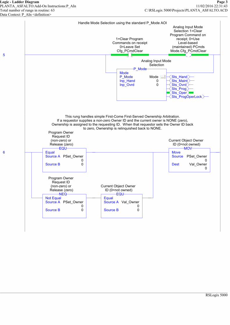
Logic - Ladder Diagram Page 3PLANTA_ASFALTO:Add-On Instructions:P_AIn 11/02/2016 22:31:43Total number of rungs in routine: 63 C:\RSLogix 5000\Projects\PLANTA_ASFALTO.ACDData Context: P_AIn <definition>
RSLogix 5000
Handle Mode Selection using the standard P_Mode AOI
5
1=Clear Program Commands on receipt
0=Leave SetCfg_PCmdClear
Analog Input Mode Selection 1=Clear
Program Command on receipt; 0=Use Level-based
(maintained) PCmdsMode.Cfg_PCmdClear
Sts_HandSts_MaintSts_OvrdSts_ProgSts_OperSts_ProgOperLock
ModeP_Mode Mode ... Inp_Hand 0Inp_Ovrd 0
P_Mode
Analog Input Mode Selection
Handle Mode Selection using the standard P_Mode AOI
This rung handles simple First-Come First-Served Ownership Arbitration.If a requestor supplies a non-zero Owner ID and the current owner is NONE (zero),
Ownership is assigned to the requesting ID. When that requestor sets the Owner ID backto zero, Ownership is relinquished back to NONE.
6 EqualSource A PSet_Owner
0Source B 0
EQU
Program Owner Request ID
(non-zero) or Release (zero)
Not EqualSource A PSet_Owner
0Source B 0
NEQ
Program Owner Request ID
(non-zero) or Release (zero)
EqualSource A Val_Owner
0Source B 0
EQU
Current Object Owner ID (0=not owned)
MoveSource PSet_Owner
0Dest Val_Owner
0
MOV
Current Object Owner ID (0=not owned)
This rung handles simple First-Come First-Served Ownership Arbitration.If a requestor supplies a non-zero Owner ID and the current owner is NONE (zero),
Ownership is assigned to the requesting ID. When that requestor sets the Owner ID backto zero, Ownership is relinquished back to NONE.

Logic - Ladder Diagram Page 4PLANTA_ASFALTO:Add-On Instructions:P_AIn 11/02/2016 22:31:43Total number of rungs in routine: 63 C:\RSLogix 5000\Projects\PLANTA_ASFALTO.ACDData Context: P_AIn <definition>
RSLogix 5000
============================================================COMMAND PROCESSING
============================================================These rungs handle received Commands:
MCmd_SubstPV: Maintenance Command to select Maintenance-entered substitute PV
Do not allow this Command if Cfg_NoSubstPV is set.
7
Maintenance Command to use Substitute PV
(override input)MCmd_SubstPV
U
Maintenance Command to use Substitute PV
(override input)MCmd_SubstPV
Analog Input Mode Selection 1=Mode is
Maintenance (supersedes Ovrd,
Prog, Oper)Mode.Sts_Maint
/
1=Disallow selection of Substitute PVCfg_NoSubstPV
L
Internal flag: Using Substitute PVWrk_SubstPV
============================================================COMMAND PROCESSING
============================================================These rungs handle received Commands:
MCmd_SubstPV: Maintenance Command to select Maintenance-entered substitute PV
Do not allow this Command if Cfg_NoSubstPV is set.
MCmd_InpPV: Maintenance Command to cancel Substitute PV and return to Live Input PV.
8
Maintenance Command to use Input PV
(normal)MCmd_InpPV
U
Maintenance Command to use Input PV
(normal)MCmd_InpPV
Analog Input Mode Selection 1=Mode is
Maintenance (supersedes Ovrd,
Prog, Oper)Mode.Sts_Maint
1=Disallow selection of Substitute PVCfg_NoSubstPV
U
Internal flag: Using Substitute PVWrk_SubstPV
MCmd_InpPV: Maintenance Command to cancel Substitute PV and return to Live Input PV.
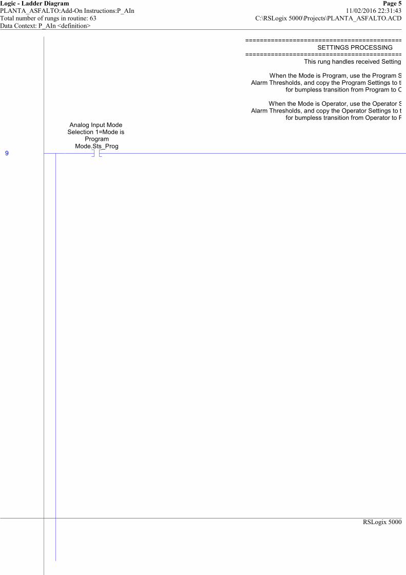
Logic - Ladder Diagram Page 5PLANTA_ASFALTO:Add-On Instructions:P_AIn 11/02/2016 22:31:43Total number of rungs in routine: 63 C:\RSLogix 5000\Projects\PLANTA_ASFALTO.ACDData Context: P_AIn <definition>
RSLogix 5000
============================================================SETTINGS PROCESSING
============================================================This rung handles received Settings:
When the Mode is Program, use the Program Settings for theAlarm Thresholds, and copy the Program Settings to the Operator Settings
for bumpless transition from Program to Operator.
When the Mode is Operator, use the Operator Settings for theAlarm Thresholds, and copy the Operator Settings to the Program Settings
for bumpless transition from Operator to Program.
9
Analog Input Mode Selection 1=Mode is
ProgramMode.Sts_Prog
============================================================SETTINGS PROCESSING
============================================================This rung handles received Settings:
When the Mode is Program, use the Program Settings for theAlarm Thresholds, and copy the Program Settings to the Operator Settings
for bumpless transition from Program to Operator.
When the Mode is Operator, use the Operator Settings for theAlarm Thresholds, and copy the Operator Settings to the Program Settings
for bumpless transition from Operator to Program.
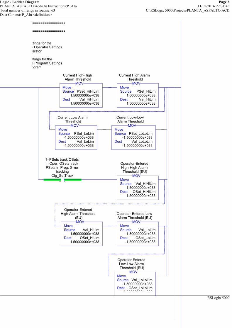
Logic - Ladder Diagram Page 6PLANTA_ASFALTO:Add-On Instructions:P_AIn 11/02/2016 22:31:43Total number of rungs in routine: 63 C:\RSLogix 5000\Projects\PLANTA_ASFALTO.ACDData Context: P_AIn <definition>
RSLogix 5000
============================================================
============================================================
When the Mode is Program, use the Program Settings for theAlarm Thresholds, and copy the Program Settings to the Operator Settings
for bumpless transition from Program to Operator.
When the Mode is Operator, use the Operator Settings for theAlarm Thresholds, and copy the Operator Settings to the Program Settings
for bumpless transition from Operator to Program.
MoveSource PSet_HiHiLim
1.50000000e+038Dest Val_HiHiLim
1.50000000e+038
MOV
Current High-High Alarm Threshold
MoveSource PSet_HiLim
1.50000000e+038Dest Val_HiLim
1.50000000e+038
MOV
Current High Alarm Threshold
MoveSource PSet_LoLim
-1.50000000e+038Dest Val_LoLim
-1.50000000e+038
MOV
Current Low Alarm Threshold
MoveSource PSet_LoLoLim
-1.50000000e+038Dest Val_LoLoLim
-1.50000000e+038
MOV
Current Low-Low Alarm Threshold
1=PSets track OSets in Oper, OSets track PSets in Prog, 0=no
trackingCfg_SetTrack
MoveSource Val_HiHiLim
1.50000000e+038Dest OSet_HiHiLim
1.50000000e+038
MOV
Operator-Entered High-High Alarm Threshold (EU)
MoveSource Val_HiLim
1.50000000e+038Dest OSet_HiLim
1.50000000e+038
MOV
Operator-Entered High Alarm Threshold
(EU)
MoveSource Val_LoLim
-1.50000000e+038Dest OSet_LoLim
-1.50000000e+038
MOV
Operator-Entered Low Alarm Threshold (EU)
MoveSource Val_LoLoLim
-1.50000000e+038Dest OSet_LoLoLim
-1.50000000e+038
MOV
Operator-Entered Low-Low Alarm Threshold (EU)
============================================================
============================================================
When the Mode is Program, use the Program Settings for theAlarm Thresholds, and copy the Program Settings to the Operator Settings
for bumpless transition from Program to Operator.
When the Mode is Operator, use the Operator Settings for theAlarm Thresholds, and copy the Operator Settings to the Program Settings
for bumpless transition from Operator to Program.
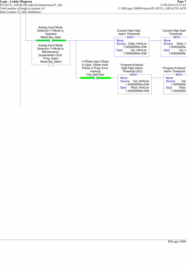
Logic - Ladder Diagram Page 7PLANTA_ASFALTO:Add-On Instructions:P_AIn 11/02/2016 22:31:43Total number of rungs in routine: 63 C:\RSLogix 5000\Projects\PLANTA_ASFALTO.ACDData Context: P_AIn <definition>
RSLogix 5000
Analog Input Mode Selection 1=Mode is
OperatorMode.Sts_Oper
Analog Input Mode Selection 1=Mode is
Maintenance (supersedes Ovrd,
Prog, Oper)Mode.Sts_Maint
MoveSource OSet_HiHiLim
1.50000000e+038Dest Val_HiHiLim
1.50000000e+038
MOV
Current High-High Alarm Threshold
MoveSource OSet_HiLim
1.50000000e+038Dest Val_HiLim
1.50000000e+038
MOV
Current High Alarm Threshold
1=PSets track OSets in Oper, OSets track PSets in Prog, 0=no
trackingCfg_SetTrack
MoveSource Val_HiHiLim
1.50000000e+038Dest PSet_HiHiLim
1.50000000e+038
MOV
Program-Entered High-High Alarm Threshold (EU)
MoveSource Val_HiLim
1.50000000e+038Dest PSet_HiLim
1.50000000e+038
MOV
Program-Entered High Alarm Threshold (EU)

Logic - Ladder Diagram Page 8PLANTA_ASFALTO:Add-On Instructions:P_AIn 11/02/2016 22:31:43Total number of rungs in routine: 63 C:\RSLogix 5000\Projects\PLANTA_ASFALTO.ACDData Context: P_AIn <definition>
RSLogix 5000
-1.50000000e+038
OSet_HiLim1.50000000e+038
Val_HiLim1.50000000e+038
MoveSource OSet_LoLim
-1.50000000e+038Dest Val_LoLim
-1.50000000e+038
MOV
Current Low Alarm Threshold
MoveSource OSet_LoLoLim
-1.50000000e+038Dest Val_LoLoLim
-1.50000000e+038
MOV
Current Low-Low Alarm Threshold
Val_HiLim1.50000000e+038
PSet_HiLim1.50000000e+038
Program-Entered High Alarm Threshold (EU)
MoveSource Val_LoLim
-1.50000000e+038Dest PSet_LoLim
-1.50000000e+038
MOV
Program-Entered Low Alarm Threshold (EU)
MoveSource Val_LoLoLim
-1.50000000e+038Dest PSet_LoLoLim
-1.50000000e+038
MOV
Program-Entered Low-Low Alarm Threshold (EU)
============================================================ANALOG INPUT PROCESSING
============================================================
This rung checks the bit pattern of the REAL input (by copying to a DINT) to see ifthe input is +Infinity, -Infinity or Not a Number. Per ANSI 32-bit Floatformat, in these cases the Exponent bits (.30 thru .23) will all be 1s:
0111 1111 1000 0000 0000 0000 0000 0000 = +Infinity1111 1111 1000 0000 0000 0000 0000 0000 = -Infinity
x111 1111 1xxx xxxx xxxx xxxx xxxx xxxx = Not a Number
10 /
1=Use simulated PV (Set_SimPV); 0=Use
Input (Inp_PV)Inp_Sim
Copy FileSource Inp_PVDest Wrk_InpDINTLength 1
COP
Input REAL bit pattern as a DINT (check for Inf/NaN)
1=Use simulated PV (Set_SimPV); 0=Use
Input (Inp_PV)Inp_Sim
Copy FileSource Set_SimPVDest Wrk_InpDINTLength 1
COP
Input REAL bit pattern as a DINT (check for Inf/NaN)
Mask EqualSource Wrk_InpDINT
0Mask 16#7F80_0000
Compare 16#7F80_0000
MEQ
Input REAL bit pattern as a DINT (check for Inf/NaN)
Input is Infinite or Not a Number
Wrk_InpInfNaN
============================================================ANALOG INPUT PROCESSING
============================================================
This rung checks the bit pattern of the REAL input (by copying to a DINT) to see ifthe input is +Infinity, -Infinity or Not a Number. Per ANSI 32-bit Floatformat, in these cases the Exponent bits (.30 thru .23) will all be 1s:
0111 1111 1000 0000 0000 0000 0000 0000 = +Infinity1111 1111 1000 0000 0000 0000 0000 0000 = -Infinity
x111 1111 1xxx xxxx xxxx xxxx xxxx xxxx = Not a Number

Logic - Ladder Diagram Page 9PLANTA_ASFALTO:Add-On Instructions:P_AIn 11/02/2016 22:31:43Total number of rungs in routine: 63 C:\RSLogix 5000\Projects\PLANTA_ASFALTO.ACDData Context: P_AIn <definition>
RSLogix 5000
Flag a Configuration Error if the raw input range or scaled PV rangemax and min are set the same (invalid range).
##### V1.1-00 2010-03-18: Rung Added to fix Err bits #####
11 EqualSource A Cfg_InpRawMax
100.0Source B Cfg_InpRawMin
0.0
EQU
Input (unscaled) Maximum for Scaling
1=Error in Config: Raw Input Scaling
Min = MaxErr_Raw
EqualSource A Cfg_PVEUMax
100.0Source B Cfg_PVEUMin
0.0
EQU
PV (Output) Maximum for Scaling to EU
1=Error in Config: Scaled EU Min = Max
Err_EU
Flag a Configuration Error if the raw input range or scaled PV rangemax and min are set the same (invalid range).
##### V1.1-00 2010-03-18: Rung Added to fix Err bits #####
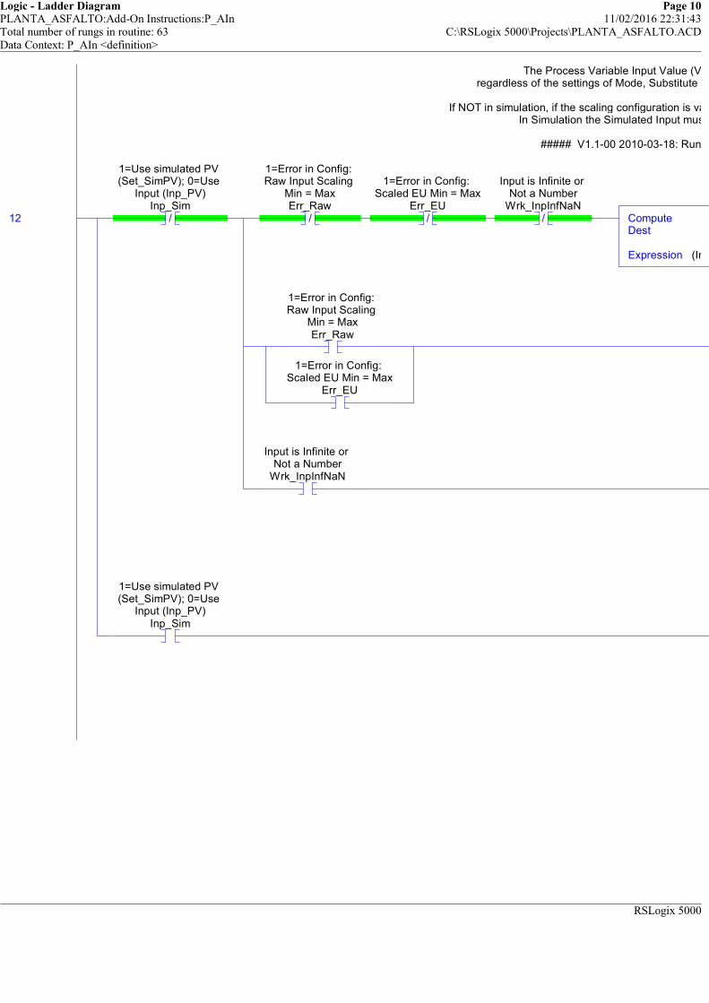
Logic - Ladder Diagram Page 10PLANTA_ASFALTO:Add-On Instructions:P_AIn 11/02/2016 22:31:43Total number of rungs in routine: 63 C:\RSLogix 5000\Projects\PLANTA_ASFALTO.ACDData Context: P_AIn <definition>
RSLogix 5000
The Process Variable Input Value (Val_InpPV) shows the scaled input,regardless of the settings of Mode, Substitute PV, etc., EVEN WHEN EnableIn IS FALSE!
If NOT in simulation, if the scaling configuration is valid, the Raw Input is scaled to Engineering Units.In Simulation the Simulated Input must be provided in Engineering Units.
##### V1.1-00 2010-03-18: Rung Modified to fix Err bits #####
12 /
1=Use simulated PV (Set_SimPV); 0=Use
Input (Inp_PV)Inp_Sim
/
1=Error in Config: Raw Input Scaling
Min = MaxErr_Raw
/
1=Error in Config: Scaled EU Min = Max
Err_EU/
Input is Infinite or Not a Number
Wrk_InpInfNaNComputeDest
Expression (Inp_PV-Cfg_InpRawMin)*(Cfg_PVEUMax-Cfg_PVEUMin)/(Cfg_InpRawMax-Cfg_InpRawMin)+Cfg_PVEUMin
1=Error in Config: Raw Input Scaling
Min = MaxErr_Raw
1=Error in Config: Scaled EU Min = Max
Err_EU
Input is Infinite or Not a Number
Wrk_InpInfNaN
1=Use simulated PV (Set_SimPV); 0=Use
Input (Inp_PV)Inp_Sim
The Process Variable Input Value (Val_InpPV) shows the scaled input,regardless of the settings of Mode, Substitute PV, etc., EVEN WHEN EnableIn IS FALSE!
If NOT in simulation, if the scaling configuration is valid, the Raw Input is scaled to Engineering Units.In Simulation the Simulated Input must be provided in Engineering Units.
##### V1.1-00 2010-03-18: Rung Modified to fix Err bits #####
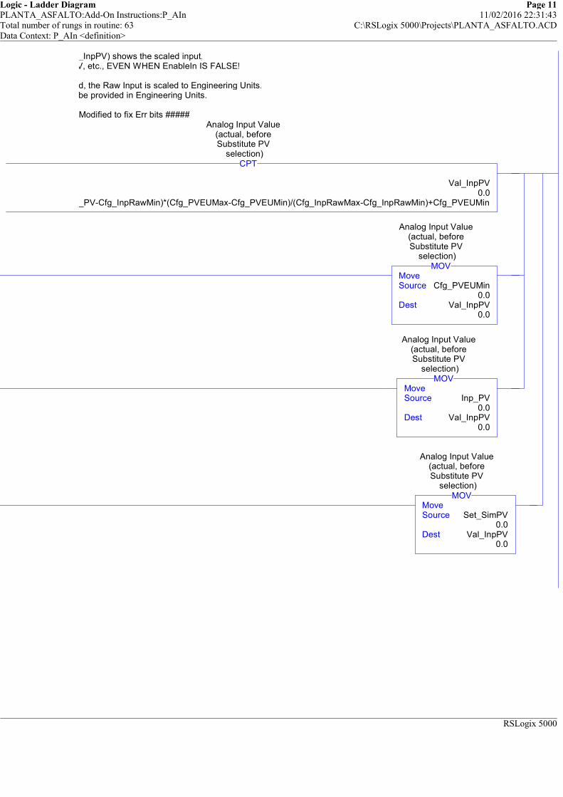
Logic - Ladder Diagram Page 11PLANTA_ASFALTO:Add-On Instructions:P_AIn 11/02/2016 22:31:43Total number of rungs in routine: 63 C:\RSLogix 5000\Projects\PLANTA_ASFALTO.ACDData Context: P_AIn <definition>
RSLogix 5000
The Process Variable Input Value (Val_InpPV) shows the scaled input,regardless of the settings of Mode, Substitute PV, etc., EVEN WHEN EnableIn IS FALSE!
If NOT in simulation, if the scaling configuration is valid, the Raw Input is scaled to Engineering Units.In Simulation the Simulated Input must be provided in Engineering Units.
##### V1.1-00 2010-03-18: Rung Modified to fix Err bits #####
Val_InpPV0.0
(Inp_PV-Cfg_InpRawMin)*(Cfg_PVEUMax-Cfg_PVEUMin)/(Cfg_InpRawMax-Cfg_InpRawMin)+Cfg_PVEUMin
CPT
Analog Input Value (actual, before Substitute PV
selection)
MoveSource Cfg_PVEUMin
0.0Dest Val_InpPV
0.0
MOV
Analog Input Value (actual, before Substitute PV
selection)
MoveSource Inp_PV
0.0Dest Val_InpPV
0.0
MOV
Analog Input Value (actual, before Substitute PV
selection)
MoveSource Set_SimPV
0.0Dest Val_InpPV
0.0
MOV
Analog Input Value (actual, before Substitute PV
selection)
The Process Variable Input Value (Val_InpPV) shows the scaled input,regardless of the settings of Mode, Substitute PV, etc., EVEN WHEN EnableIn IS FALSE!
If NOT in simulation, if the scaling configuration is valid, the Raw Input is scaled to Engineering Units.In Simulation the Simulated Input must be provided in Engineering Units.
##### V1.1-00 2010-03-18: Rung Modified to fix Err bits #####

Logic - Ladder Diagram Page 12PLANTA_ASFALTO:Add-On Instructions:P_AIn 11/02/2016 22:31:43Total number of rungs in routine: 63 C:\RSLogix 5000\Projects\PLANTA_ASFALTO.ACDData Context: P_AIn <definition>
RSLogix 5000

Logic - Ladder Diagram Page 13PLANTA_ASFALTO:Add-On Instructions:P_AIn 11/02/2016 22:31:43Total number of rungs in routine: 63 C:\RSLogix 5000\Projects\PLANTA_ASFALTO.ACDData Context: P_AIn <definition>
RSLogix 5000
When this Analog Input is not simulated and tracking is configured ON (default),the Simulated PV Setting tracks the selected PV for bumpless transfer into Simulation.
13 /
1=Use simulated PV (Set_SimPV); 0=Use
Input (Inp_PV)Inp_Sim
1=PSets track OSets in Oper, OSets track PSets in Prog, 0=no
trackingCfg_SetTrack
MoveSource Val_InpPV
0.0Dest Set_SimPV
0.0
MOV
PV used in Simulation
(Inp_Sim=1) (EU)
When this Analog Input is not simulated and tracking is configured ON (default),the Simulated PV Setting tracks the selected PV for bumpless transfer into Simulation.
The Value shows the selected PV.With Substitute PV enabled, it's the value of the entered MSet_SubstPV.
In normal operation, it's the value (Val_InpPV) selected above:the scaled Input (Inp_PV) or Simulatied PV (Set_SimPV).
14 /
1=Using Substitute PV (Input being
overridden)Sts_SubstPV
MoveSource Val_InpPV
0.0Dest Wrk_UnfiltPV
0.0
MOV
Unfiltered PV, input to 1st order filter
Internal flag: Using Substitute PVWrk_SubstPV
MoveSource MSet_SubstPV
0.0Dest Wrk_UnfiltPV
0.0
MOV
Unfiltered PV, input to 1st order filter
1=PSets track OSets in Oper, OSets track PSets in Prog, 0=no
trackingCfg_SetTrack
MoveSource Wrk_UnfiltPV
0.0Dest MSet_SubstPV
0.0
MOV
Maintenance-Entered Substitute PV (EU)
The Value shows the selected PV.With Substitute PV enabled, it's the value of the entered MSet_SubstPV.
In normal operation, it's the value (Val_InpPV) selected above:the scaled Input (Inp_PV) or Simulatied PV (Set_SimPV).

Logic - Ladder Diagram Page 14PLANTA_ASFALTO:Add-On Instructions:P_AIn 11/02/2016 22:31:43Total number of rungs in routine: 63 C:\RSLogix 5000\Projects\PLANTA_ASFALTO.ACDData Context: P_AIn <definition>
RSLogix 5000
This rung determines whether the Analog PV (unfiltered) is +/-Infinity or +/- NotANumber.In either case, the value cannot be passed into the filter calculation. Instead, it is
just copied to the PV directly.
15 Copy FileSource Wrk_UnfiltPVDest Wrk_SelPVDINTLength 1
COP
Selected PV check for Infinite or Non
A Number
Mask EqualSource Wrk_SelPVDINT
0Mask 16#7F80_0000
Compare 16#7F80_0000
MEQ
Selected PV check for Infinite or Non
A Number
Selected PV (Input or Substitute) is Infinite or NaN
Wrk_SelPVInfNaN
This rung determines whether the Analog PV (unfiltered) is +/-Infinity or +/- NotANumber.In either case, the value cannot be passed into the filter calculation. Instead, it is
just copied to the PV directly.
In preparation for calculating the Filtered PV, this rungdetermines the time since the previous scan, using a non-stop TON timer.
When we get here, we read the accumulator (in milliseconds, sodivide by 1000.0 to get seconds), then clear the accumulator. Next scan the accumulator will have
incremented up to the number of milliseconds since last scan. (Works for scan times up to 2 million seconds.....)
16 MoveSource 2147483647
Dest Wrk_ScanT.PRE2147483647
MOV
Scan Timer (milliseconds, always runs)
EN
DN
Timer On DelayTimer Wrk_ScanTPreset 2147483647Accum 0
TON
Scan Timer (milliseconds, always runs)
DivideSource A Wrk_ScanT.ACC
0Source B 1000.0
Dest Wrk_ScanTime0.0
DIV
Time since this instance was last
scanned
ClearDest Wrk_ScanT.ACC
0
CLR
Scan Timer (milliseconds, always runs)
In preparation for calculating the Filtered PV, this rungdetermines the time since the previous scan, using a non-stop TON timer.
When we get here, we read the accumulator (in milliseconds, sodivide by 1000.0 to get seconds), then clear the accumulator. Next scan the accumulator will have
incremented up to the number of milliseconds since last scan. (Works for scan times up to 2 million seconds.....)
If the input was +/-Infinity or Not a Number and it becomes a valid number,initialize the filter to start from the first valid value.
17 /
Selected PV (Input or Substitute) is Infinite or NaN
Wrk_SelPVInfNaNONS
Selected PV goes from Infinite or Not a Number to VALID
Wrk_ValidONSMoveSource Wrk_UnfiltPV
0.0Dest Wrk_FiltPV
0.0
MOVFiltered PV
If the input was +/-Infinity or Not a Number and it becomes a valid number,initialize the filter to start from the first valid value.
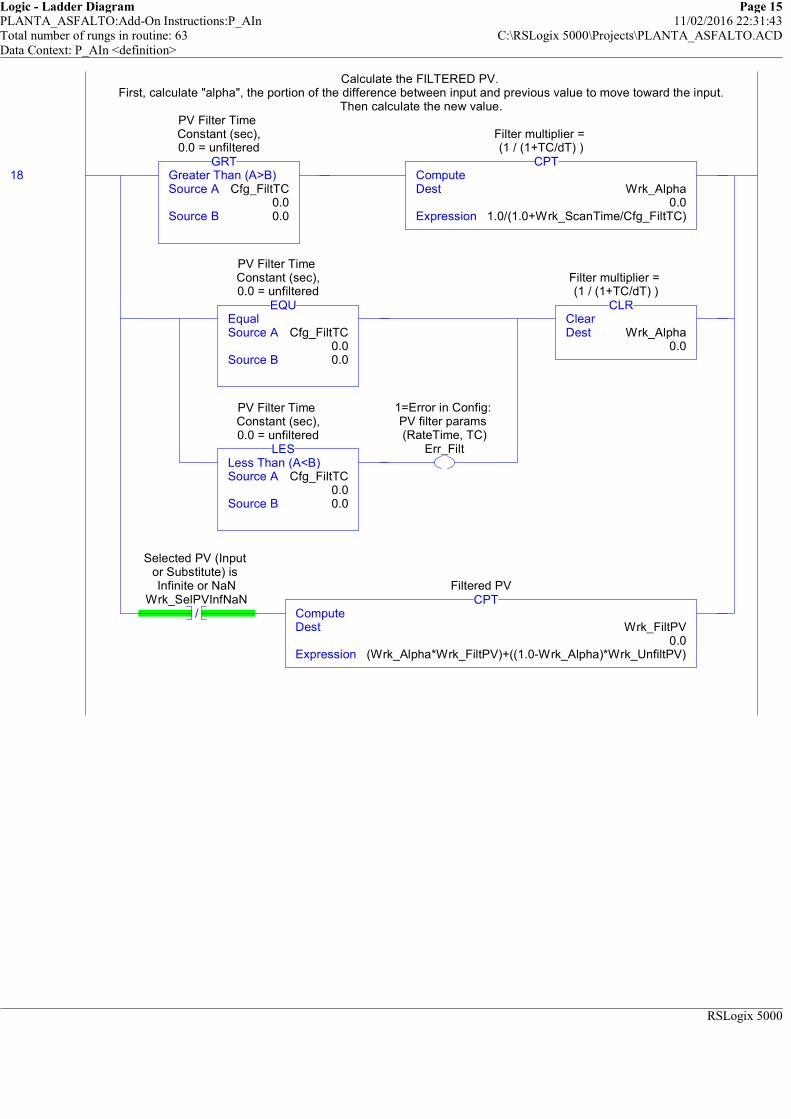
Logic - Ladder Diagram Page 15PLANTA_ASFALTO:Add-On Instructions:P_AIn 11/02/2016 22:31:43Total number of rungs in routine: 63 C:\RSLogix 5000\Projects\PLANTA_ASFALTO.ACDData Context: P_AIn <definition>
RSLogix 5000
Calculate the FILTERED PV. First, calculate "alpha", the portion of the difference between input and previous value to move toward the input.
Then calculate the new value.
18 Greater Than (A>B)Source A Cfg_FiltTC
0.0Source B 0.0
GRT
PV Filter Time Constant (sec),0.0 = unfiltered
ComputeDest Wrk_Alpha
0.0Expression 1.0/(1.0+Wrk_ScanTime/Cfg_FiltTC)
CPT
Filter multiplier = (1 / (1+TC/dT) )
EqualSource A Cfg_FiltTC
0.0Source B 0.0
EQU
PV Filter Time Constant (sec),0.0 = unfiltered
Less Than (A<B)Source A Cfg_FiltTC
0.0Source B 0.0
LES
PV Filter Time Constant (sec),0.0 = unfiltered
1=Error in Config: PV filter params (RateTime, TC)
Err_Filt
ClearDest Wrk_Alpha
0.0
CLR
Filter multiplier = (1 / (1+TC/dT) )
/
Selected PV (Input or Substitute) is Infinite or NaN
Wrk_SelPVInfNaNComputeDest Wrk_FiltPV
0.0Expression (Wrk_Alpha*Wrk_FiltPV)+((1.0-Wrk_Alpha)*Wrk_UnfiltPV)
CPTFiltered PV
Calculate the FILTERED PV. First, calculate "alpha", the portion of the difference between input and previous value to move toward the input.
Then calculate the new value.
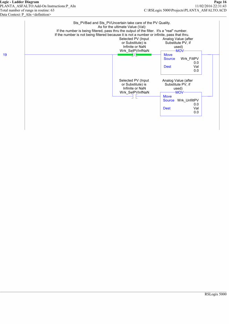
Logic - Ladder Diagram Page 16PLANTA_ASFALTO:Add-On Instructions:P_AIn 11/02/2016 22:31:43Total number of rungs in routine: 63 C:\RSLogix 5000\Projects\PLANTA_ASFALTO.ACDData Context: P_AIn <definition>
RSLogix 5000
Sts_PVBad and Sts_PVUncertain take care of the PV Quality.As for the ultimate Value (Val):
If the number is being filtered, pass thru the output of the filter. It's a "real" number.If the number is not being filtered because it is not a number or infinite, pass that thru.
19 /
Selected PV (Input or Substitute) is Infinite or NaN
Wrk_SelPVInfNaNMoveSource Wrk_FiltPV
0.0Dest Val
0.0
MOV
Analog Value (after Substitute PV, if
used)
Selected PV (Input or Substitute) is Infinite or NaN
Wrk_SelPVInfNaNMoveSource Wrk_UnfiltPV
0.0Dest Val
0.0
MOV
Analog Value (after Substitute PV, if
used)
Sts_PVBad and Sts_PVUncertain take care of the PV Quality.As for the ultimate Value (Val):
If the number is being filtered, pass thru the output of the filter. It's a "real" number.If the number is not being filtered because it is not a number or infinite, pass that thru.
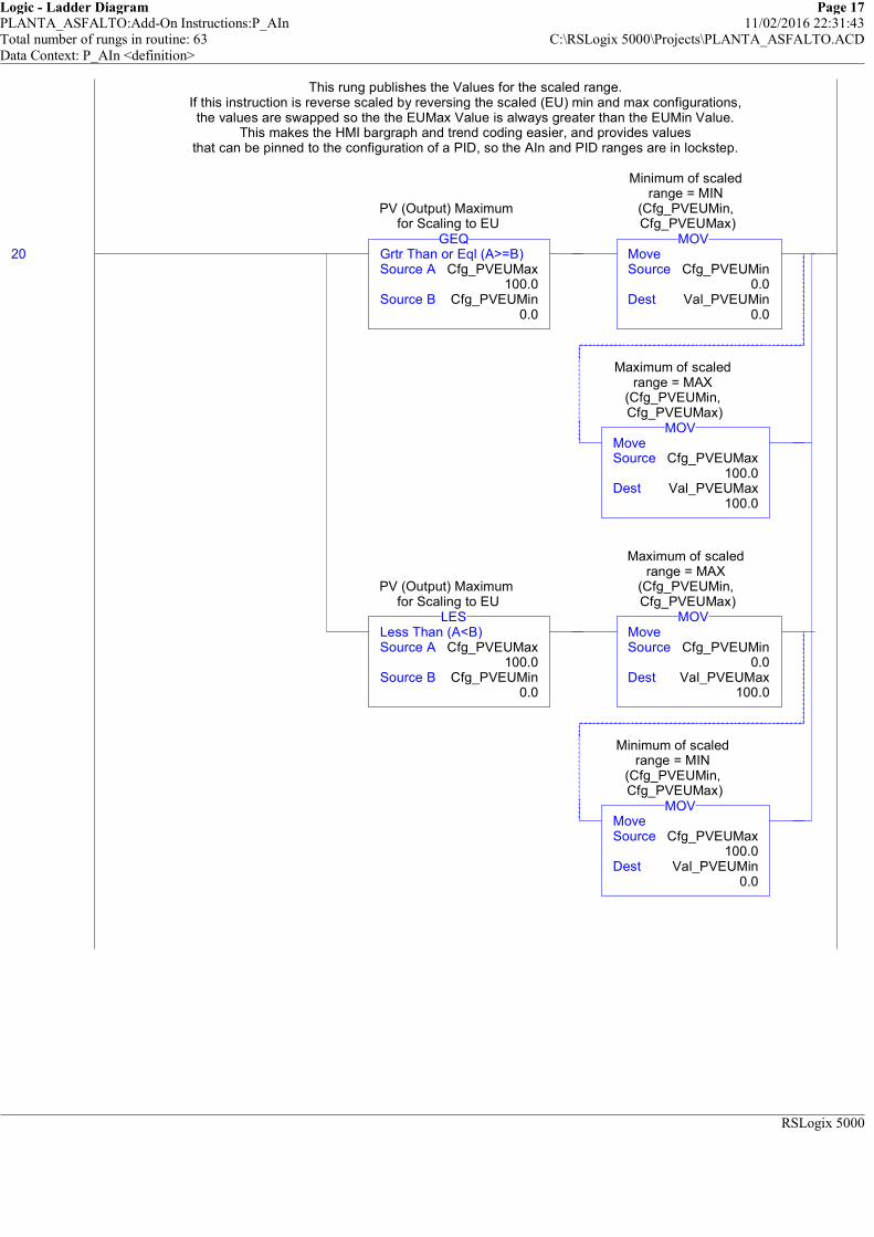
Logic - Ladder Diagram Page 17PLANTA_ASFALTO:Add-On Instructions:P_AIn 11/02/2016 22:31:43Total number of rungs in routine: 63 C:\RSLogix 5000\Projects\PLANTA_ASFALTO.ACDData Context: P_AIn <definition>
RSLogix 5000
This rung publishes the Values for the scaled range.If this instruction is reverse scaled by reversing the scaled (EU) min and max configurations,the values are swapped so the the EUMax Value is always greater than the EUMin Value.
This makes the HMI bargraph and trend coding easier, and provides valuesthat can be pinned to the configuration of a PID, so the AIn and PID ranges are in lockstep.
20 Grtr Than or Eql (A>=B)Source A Cfg_PVEUMax
100.0Source B Cfg_PVEUMin
0.0
GEQ
PV (Output) Maximum for Scaling to EU
MoveSource Cfg_PVEUMin
0.0Dest Val_PVEUMin
0.0
MOV
Minimum of scaled range = MIN
(Cfg_PVEUMin, Cfg_PVEUMax)
MoveSource Cfg_PVEUMax
100.0Dest Val_PVEUMax
100.0
MOV
Maximum of scaled range = MAX
(Cfg_PVEUMin, Cfg_PVEUMax)
Less Than (A<B)Source A Cfg_PVEUMax
100.0Source B Cfg_PVEUMin
0.0
LES
PV (Output) Maximum for Scaling to EU
MoveSource Cfg_PVEUMin
0.0Dest Val_PVEUMax
100.0
MOV
Maximum of scaled range = MAX
(Cfg_PVEUMin, Cfg_PVEUMax)
MoveSource Cfg_PVEUMax
100.0Dest Val_PVEUMin
0.0
MOV
Minimum of scaled range = MIN
(Cfg_PVEUMin, Cfg_PVEUMax)
This rung publishes the Values for the scaled range.If this instruction is reverse scaled by reversing the scaled (EU) min and max configurations,the values are swapped so the the EUMax Value is always greater than the EUMin Value.
This makes the HMI bargraph and trend coding easier, and provides valuesthat can be pinned to the configuration of a PID, so the AIn and PID ranges are in lockstep.

Logic - Ladder Diagram Page 18PLANTA_ASFALTO:Add-On Instructions:P_AIn 11/02/2016 22:31:43Total number of rungs in routine: 63 C:\RSLogix 5000\Projects\PLANTA_ASFALTO.ACDData Context: P_AIn <definition>
RSLogix 5000
============================================================ALARM RESET COMMAND HANDLING
============================================================This rung handles the Alarm Reset Input and Commands.
21
Program Command to Reset all Alarms requiring ResetPCmd_Reset
1=Clear Program Commands on receipt
0=Leave SetCfg_PCmdClear
U
Program Command to Reset all Alarms requiring ResetPCmd_Reset
NOP
Operator Command to Reset all Alarms requiring ResetOCmd_Reset
U
Operator Command to Reset all Alarms requiring ResetOCmd_Reset
1=Reset all Alarms requiring reset
Inp_Reset
L
High-High Alarm Program Command to
Reset latched alarmHiHi.PCmd_Reset
L
High Alarm Program Command to Reset
latched alarmHi.PCmd_Reset
L
Low Alarm Program Command to Reset
latched alarmLo.PCmd_Reset
L
Low-Low Alarm Program Command to
Reset latched alarmLoLo.PCmd_Reset
L
Analog Input Failure Alarm (bad quality
or out of range) Program Command to
Reset latched alarmFail.PCmd_Reset
============================================================ALARM RESET COMMAND HANDLING
============================================================This rung handles the Alarm Reset Input and Commands.

Logic - Ladder Diagram Page 19PLANTA_ASFALTO:Add-On Instructions:P_AIn 11/02/2016 22:31:43Total number of rungs in routine: 63 C:\RSLogix 5000\Projects\PLANTA_ASFALTO.ACDData Context: P_AIn <definition>
RSLogix 5000
============================================================ANALOG ALARM PROCESSING
============================================================The following rungs process the High-High Analog Alarm.
If the Analog Value exceeds the High-High limit, or has not fallen backbelow the limit minus deadband, issue a High-High Alarm to the contained P_Alarm block.
(The contained block takes care of the alarm delay, acknowledgement, reset, etc.)
22 Grtr Than or Eql (A>=B)Source A Val
0.0Source B Val_HiHiLim
1.50000000e+038
GEQ
Analog Value (after Substitute PV, if
used)
1=Analog Input is above High-High
limitSts_HiHi
CompareExpression Val>=(Val_HiHiLim-Cfg_HiHiDB)
CMP
1=Analog Input is above High-High
limitSts_HiHi
High-High Alarm Alarm Condition
Input 1=AlarmHiHi.Inp
============================================================ANALOG ALARM PROCESSING
============================================================The following rungs process the High-High Analog Alarm.
If the Analog Value exceeds the High-High limit, or has not fallen backbelow the limit minus deadband, issue a High-High Alarm to the contained P_Alarm block.
(The contained block takes care of the alarm delay, acknowledgement, reset, etc.)
PCmd_HiHiAck: Program Command to Acknowledge the High-High Alarm
23
Program Command to Acknowledge
High-High AlarmPCmd_HiHiAck
1=Clear Program Commands on receipt
0=Leave SetCfg_PCmdClear
U
Program Command to Acknowledge
High-High AlarmPCmd_HiHiAck
L
High-High Alarm Program Command to
Acknowledge alarmHiHi.PCmd_Ack
PCmd_HiHiAck: Program Command to Acknowledge the High-High Alarm
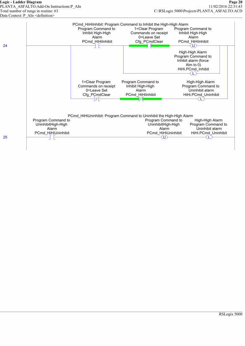
Logic - Ladder Diagram Page 20PLANTA_ASFALTO:Add-On Instructions:P_AIn 11/02/2016 22:31:43Total number of rungs in routine: 63 C:\RSLogix 5000\Projects\PLANTA_ASFALTO.ACDData Context: P_AIn <definition>
RSLogix 5000
PCmd_HiHiInhibit: Program Command to Inhibit the High-High Alarm
24
Program Command to Inhibit High-High
AlarmPCmd_HiHiInhibit
1=Clear Program Commands on receipt
0=Leave SetCfg_PCmdClear
U
Program Command to Inhibit High-High
AlarmPCmd_HiHiInhibit
L
High-High Alarm Program Command to
Inhibit alarm (force Alm to 0)
HiHi.PCmd_Inhibit
/
1=Clear Program Commands on receipt
0=Leave SetCfg_PCmdClear
/
Program Command to Inhibit High-High
AlarmPCmd_HiHiInhibit
L
High-High Alarm Program Command to
Uninhibit alarmHiHi.PCmd_Uninhibit
PCmd_HiHiInhibit: Program Command to Inhibit the High-High Alarm
PCmd_HiHiUninhibit: Program Command to Uninhibit the High-High Alarm
25
Program Command to UninhibitHigh-High
AlarmPCmd_HiHiUninhibit
U
Program Command to UninhibitHigh-High
AlarmPCmd_HiHiUninhibit
L
High-High Alarm Program Command to
Uninhibit alarmHiHi.PCmd_Uninhibit
PCmd_HiHiUninhibit: Program Command to Uninhibit the High-High Alarm

Logic - Ladder Diagram Page 21PLANTA_ASFALTO:Add-On Instructions:P_AIn 11/02/2016 22:31:43Total number of rungs in routine: 63 C:\RSLogix 5000\Projects\PLANTA_ASFALTO.ACDData Context: P_AIn <definition>
RSLogix 5000
Move Alarm configuration data into the P_Alarm Add-On Instruction:
##### V1.1-00 2010-03-18: Added: Exists: Alarm exists and logic must be scanned #####AckReqd: Alarm must be acknowledged
ResetReqd: Alarm latched in, must be cleared via Reset CommandSeverity: 1=Info, 2=Warning, 3=Exception, 4=Equipment Fault
MinDuration: Alarm must stay on at least this long to be seen by HMI poll
Handle High-High Alarm Processing using the standard P_Alarm AOI
26
1=High-High Alarm exists and will be
checkedCfg_HasHiHiAlm
High-High Alarm 1=Alarm configured to exist, 0=Does not
exist, don't scanHiHi.Cfg_Exists
1=Acknowledge required for
High-High AlarmCfg_HiHiAckReqd
High-High Alarm 1=Acknowledge
required for AlarmHiHi.Cfg_AckReqd
1=Reset required to clear High-High
AlarmCfg_HiHiResetReqd
High-High Alarm 1=Reset required to
clear AlarmHiHi.Cfg_ResetReqd
MoveSource Cfg_HiHiSeverity
3Dest HiHi.Cfg_Severity
3
MOV
High-High Alarm 1=Info Only;
2=Warning; 3=Process Exception; 4=Fault
MoveSource Cfg_HiHiMinDuration
0Dest HiHi.Cfg_MinDuration
0
MOV
High-High Alarm Minimum time (sec) Input must stay on to generate Alarm
Move Alarm configuration data into the P_Alarm Add-On Instruction:
##### V1.1-00 2010-03-18: Added: Exists: Alarm exists and logic must be scanned #####AckReqd: Alarm must be acknowledged
ResetReqd: Alarm latched in, must be cleared via Reset CommandSeverity: 1=Info, 2=Warning, 3=Exception, 4=Equipment Fault
MinDuration: Alarm must stay on at least this long to be seen by HMI poll
27AlmAckInhibitedSuppressedDisabled
AlarmP_Alarm HiHi ... Inp 1Inp_Reset 0
P_AlarmHigh-High Alarm
Handle High-High Alarm Processing using the standard P_Alarm AOI
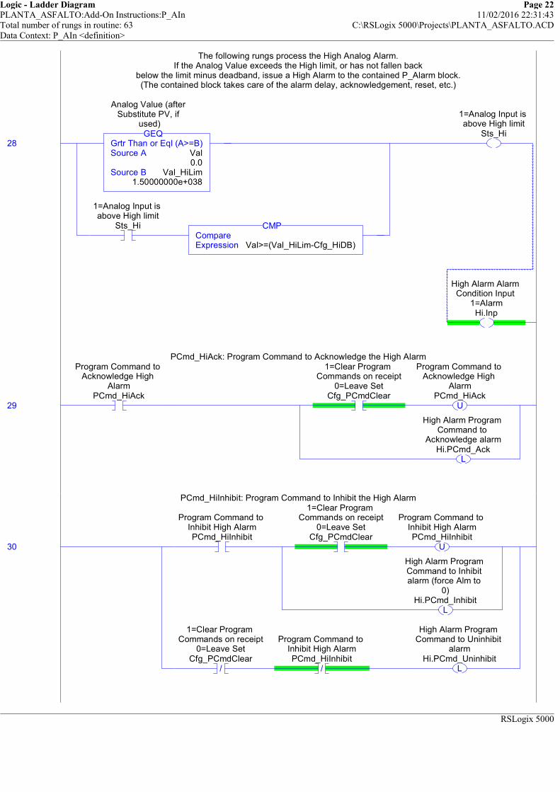
Logic - Ladder Diagram Page 22PLANTA_ASFALTO:Add-On Instructions:P_AIn 11/02/2016 22:31:43Total number of rungs in routine: 63 C:\RSLogix 5000\Projects\PLANTA_ASFALTO.ACDData Context: P_AIn <definition>
RSLogix 5000
The following rungs process the High Analog Alarm.If the Analog Value exceeds the High limit, or has not fallen back
below the limit minus deadband, issue a High Alarm to the contained P_Alarm block.(The contained block takes care of the alarm delay, acknowledgement, reset, etc.)
28 Grtr Than or Eql (A>=B)Source A Val
0.0Source B Val_HiLim
1.50000000e+038
GEQ
Analog Value (after Substitute PV, if
used)
1=Analog Input is above High limit
Sts_HiCompareExpression Val>=(Val_HiLim-Cfg_HiDB)
CMP
1=Analog Input is above High limit
Sts_Hi
High Alarm Alarm Condition Input
1=AlarmHi.Inp
The following rungs process the High Analog Alarm.If the Analog Value exceeds the High limit, or has not fallen back
below the limit minus deadband, issue a High Alarm to the contained P_Alarm block.(The contained block takes care of the alarm delay, acknowledgement, reset, etc.)
PCmd_HiAck: Program Command to Acknowledge the High Alarm
29
Program Command to Acknowledge High
AlarmPCmd_HiAck
1=Clear Program Commands on receipt
0=Leave SetCfg_PCmdClear
U
Program Command to Acknowledge High
AlarmPCmd_HiAck
L
High Alarm Program Command to
Acknowledge alarmHi.PCmd_Ack
PCmd_HiAck: Program Command to Acknowledge the High Alarm
PCmd_HiInhibit: Program Command to Inhibit the High Alarm
30
Program Command to Inhibit High AlarmPCmd_HiInhibit
1=Clear Program Commands on receipt
0=Leave SetCfg_PCmdClear
U
Program Command to Inhibit High AlarmPCmd_HiInhibit
L
High Alarm Program Command to Inhibit alarm (force Alm to
0)Hi.PCmd_Inhibit
/
1=Clear Program Commands on receipt
0=Leave SetCfg_PCmdClear
/
Program Command to Inhibit High AlarmPCmd_HiInhibit
L
High Alarm Program Command to Uninhibit
alarmHi.PCmd_Uninhibit
PCmd_HiInhibit: Program Command to Inhibit the High Alarm
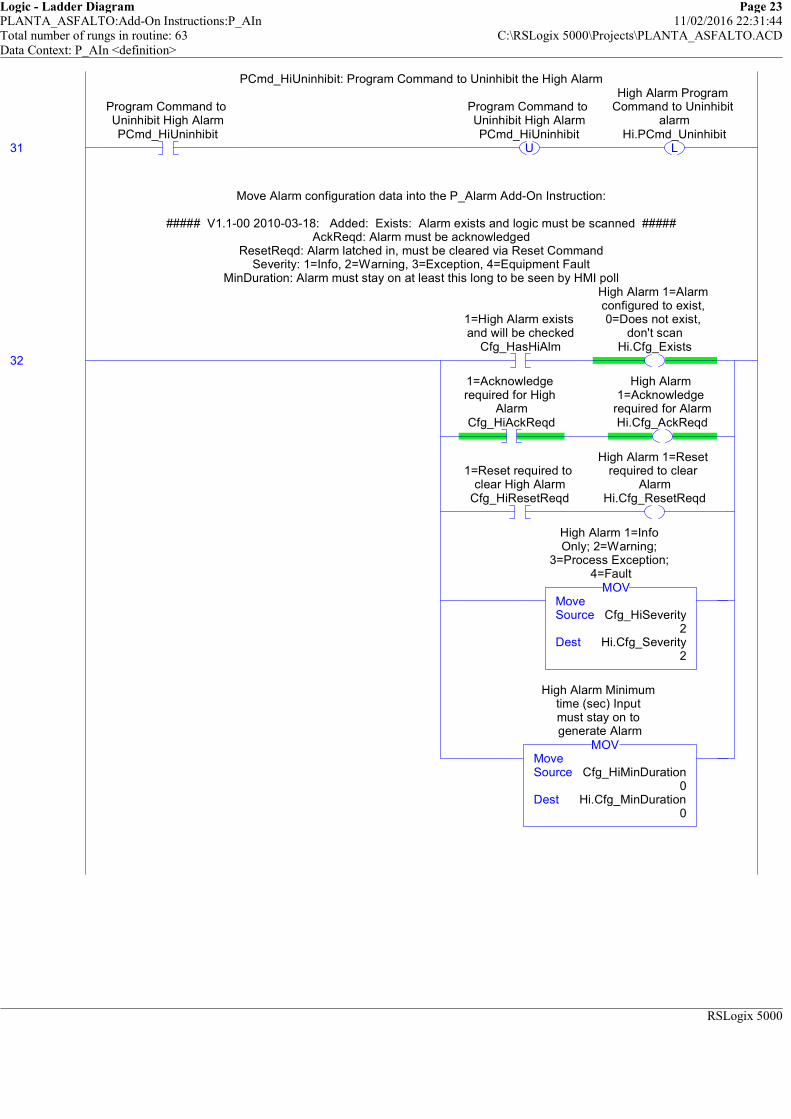
Logic - Ladder Diagram Page 23PLANTA_ASFALTO:Add-On Instructions:P_AIn 11/02/2016 22:31:44Total number of rungs in routine: 63 C:\RSLogix 5000\Projects\PLANTA_ASFALTO.ACDData Context: P_AIn <definition>
RSLogix 5000
PCmd_HiUninhibit: Program Command to Uninhibit the High Alarm
31
Program Command to Uninhibit High AlarmPCmd_HiUninhibit
U
Program Command to Uninhibit High AlarmPCmd_HiUninhibit
L
High Alarm Program Command to Uninhibit
alarmHi.PCmd_Uninhibit
PCmd_HiUninhibit: Program Command to Uninhibit the High Alarm
Move Alarm configuration data into the P_Alarm Add-On Instruction:
##### V1.1-00 2010-03-18: Added: Exists: Alarm exists and logic must be scanned #####AckReqd: Alarm must be acknowledged
ResetReqd: Alarm latched in, must be cleared via Reset CommandSeverity: 1=Info, 2=Warning, 3=Exception, 4=Equipment Fault
MinDuration: Alarm must stay on at least this long to be seen by HMI poll
32
1=High Alarm exists and will be checked
Cfg_HasHiAlm
High Alarm 1=Alarm configured to exist, 0=Does not exist,
don't scanHi.Cfg_Exists
1=Acknowledge required for High
AlarmCfg_HiAckReqd
High Alarm 1=Acknowledge
required for AlarmHi.Cfg_AckReqd
1=Reset required to clear High Alarm
Cfg_HiResetReqd
High Alarm 1=Reset required to clear
AlarmHi.Cfg_ResetReqd
MoveSource Cfg_HiSeverity
2Dest Hi.Cfg_Severity
2
MOV
High Alarm 1=Info Only; 2=Warning;
3=Process Exception; 4=Fault
MoveSource Cfg_HiMinDuration
0Dest Hi.Cfg_MinDuration
0
MOV
High Alarm Minimum time (sec) Input must stay on to generate Alarm
Move Alarm configuration data into the P_Alarm Add-On Instruction:
##### V1.1-00 2010-03-18: Added: Exists: Alarm exists and logic must be scanned #####AckReqd: Alarm must be acknowledged
ResetReqd: Alarm latched in, must be cleared via Reset CommandSeverity: 1=Info, 2=Warning, 3=Exception, 4=Equipment Fault
MinDuration: Alarm must stay on at least this long to be seen by HMI poll

Logic - Ladder Diagram Page 24PLANTA_ASFALTO:Add-On Instructions:P_AIn 11/02/2016 22:31:44Total number of rungs in routine: 63 C:\RSLogix 5000\Projects\PLANTA_ASFALTO.ACDData Context: P_AIn <definition>
RSLogix 5000
Handle High Alarm Processing using the standard P_Alarm AOI
33AlmAckInhibitedSuppressedDisabled
AlarmP_Alarm Hi ... Inp 1Inp_Reset 0
P_AlarmHigh Alarm
Handle High Alarm Processing using the standard P_Alarm AOI
The following rungs process the Low Analog Alarm.If the Analog Value falls below the Low limit, or has not risen back
above the limit plus deadband, issue a Low Alarm to the contained P_Alarm block.(The contained block takes care of the alarm delay, acknowledgement, reset, etc.)
34 Less Than or Eql (A<=B)Source A Val
0.0Source B Val_LoLim
-1.50000000e+038
LEQ
Analog Value (after Substitute PV, if
used)
1=Analog Input is below Low limit
Sts_LoCompareExpression Val<=(Val_LoLim+Cfg_LoDB)
CMP
1=Analog Input is below Low limit
Sts_Lo
Low Alarm Alarm Condition Input
1=AlarmLo.Inp
The following rungs process the Low Analog Alarm.If the Analog Value falls below the Low limit, or has not risen back
above the limit plus deadband, issue a Low Alarm to the contained P_Alarm block.(The contained block takes care of the alarm delay, acknowledgement, reset, etc.)
PCmd_LoAck: Program Command to Acknowledge the Low Alarm
35
Program Command to Acknowledge Low
AlarmPCmd_LoAck
1=Clear Program Commands on receipt
0=Leave SetCfg_PCmdClear
U
Program Command to Acknowledge Low
AlarmPCmd_LoAck
L
Low Alarm Program Command to
Acknowledge alarmLo.PCmd_Ack
PCmd_LoAck: Program Command to Acknowledge the Low Alarm
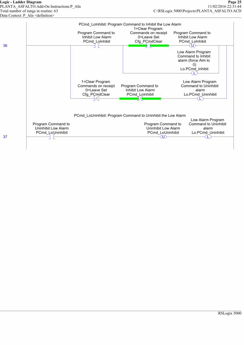
Logic - Ladder Diagram Page 25PLANTA_ASFALTO:Add-On Instructions:P_AIn 11/02/2016 22:31:44Total number of rungs in routine: 63 C:\RSLogix 5000\Projects\PLANTA_ASFALTO.ACDData Context: P_AIn <definition>
RSLogix 5000
PCmd_LoInhibit: Program Command to Inhibit the Low Alarm
36
Program Command to Inhibit Low AlarmPCmd_LoInhibit
1=Clear Program Commands on receipt
0=Leave SetCfg_PCmdClear
U
Program Command to Inhibit Low AlarmPCmd_LoInhibit
L
Low Alarm Program Command to Inhibit alarm (force Alm to
0)Lo.PCmd_Inhibit
/
1=Clear Program Commands on receipt
0=Leave SetCfg_PCmdClear
/
Program Command to Inhibit Low AlarmPCmd_LoInhibit
L
Low Alarm Program Command to Uninhibit
alarmLo.PCmd_Uninhibit
PCmd_LoInhibit: Program Command to Inhibit the Low Alarm
PCmd_LoUninhibit: Program Command to Uninhibit the Low Alarm
37
Program Command to Uninhibit Low AlarmPCmd_LoUninhibit
U
Program Command to Uninhibit Low AlarmPCmd_LoUninhibit
L
Low Alarm Program Command to Uninhibit
alarmLo.PCmd_Uninhibit
PCmd_LoUninhibit: Program Command to Uninhibit the Low Alarm

Logic - Ladder Diagram Page 26PLANTA_ASFALTO:Add-On Instructions:P_AIn 11/02/2016 22:31:44Total number of rungs in routine: 63 C:\RSLogix 5000\Projects\PLANTA_ASFALTO.ACDData Context: P_AIn <definition>
RSLogix 5000
Move Alarm configuration data into the P_Alarm Add-On Instruction:
##### V1.1-00 2010-03-18: Added: Exists: Alarm exists and logic must be scanned #####AckReqd: Alarm must be acknowledged
ResetReqd: Alarm latched in, must be cleared via Reset CommandSeverity: 1=Info, 2=Warning, 3=Exception, 4=Equipment Fault
MinDuration: Alarm must stay on at least this long to be seen by HMI poll
Handle Low Alarm Processing using the standard P_Alarm AOI
38
1=Low Alarm exists and will be checked
Cfg_HasLoAlm
Low Alarm 1=Alarm configured to exist, 0=Does not exist,
don't scanLo.Cfg_Exists
1=Acknlowledge required for Low
AlarmCfg_LoAckReqd
Low Alarm 1=Acknowledge
required for AlarmLo.Cfg_AckReqd
1=Reset required to clear Low Alarm
Cfg_LoResetReqd
Low Alarm 1=Reset required to clear
AlarmLo.Cfg_ResetReqd
MoveSource Cfg_LoSeverity
2Dest Lo.Cfg_Severity
3
MOV
Low Alarm 1=Info Only; 2=Warning;
3=Process Exception; 4=Fault
MoveSource Cfg_LoMinDuration
0Dest Lo.Cfg_MinDuration
0
MOV
Low Alarm Minimum time (sec) Input must stay on to generate Alarm
Move Alarm configuration data into the P_Alarm Add-On Instruction:
##### V1.1-00 2010-03-18: Added: Exists: Alarm exists and logic must be scanned #####AckReqd: Alarm must be acknowledged
ResetReqd: Alarm latched in, must be cleared via Reset CommandSeverity: 1=Info, 2=Warning, 3=Exception, 4=Equipment Fault
MinDuration: Alarm must stay on at least this long to be seen by HMI poll
39AlmAckInhibitedSuppressedDisabled
AlarmP_Alarm Lo ... Inp 1Inp_Reset 0
P_AlarmLow Alarm
Handle Low Alarm Processing using the standard P_Alarm AOI
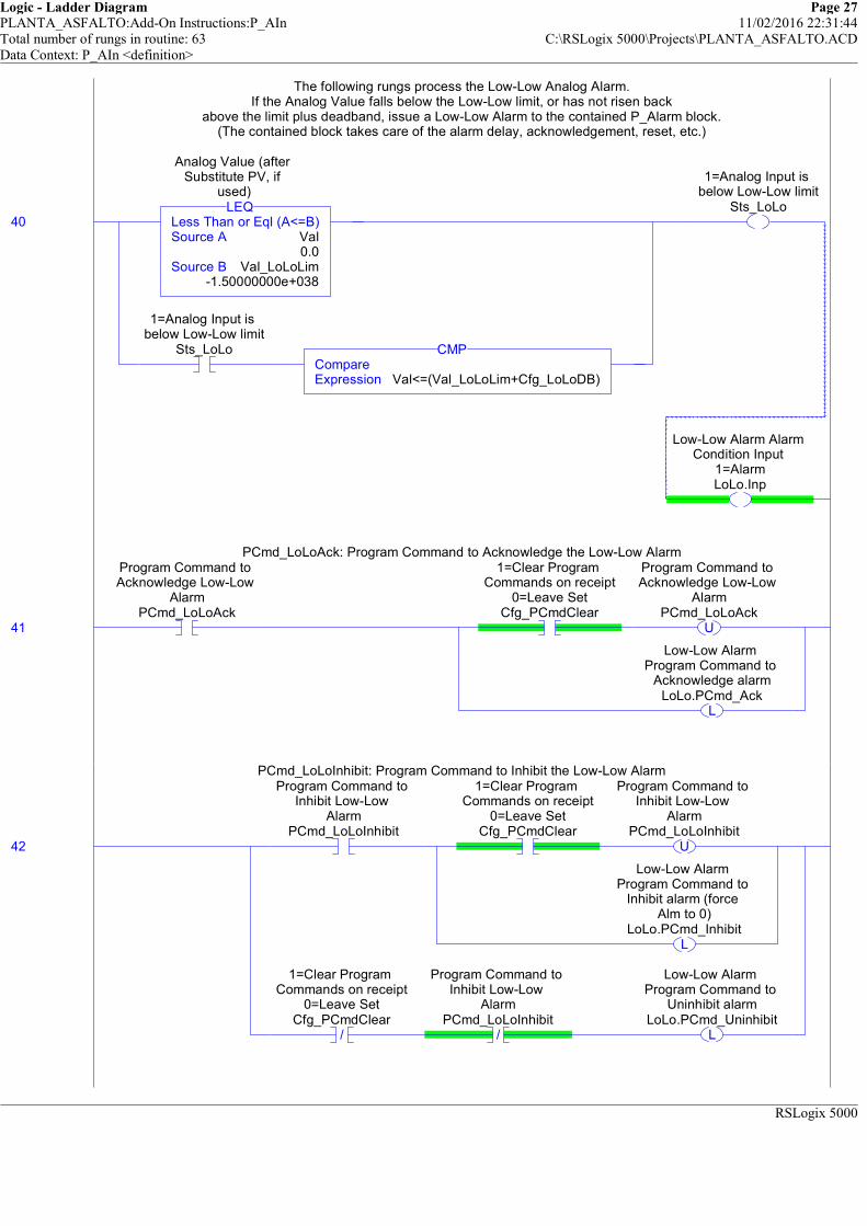
Logic - Ladder Diagram Page 27PLANTA_ASFALTO:Add-On Instructions:P_AIn 11/02/2016 22:31:44Total number of rungs in routine: 63 C:\RSLogix 5000\Projects\PLANTA_ASFALTO.ACDData Context: P_AIn <definition>
RSLogix 5000
The following rungs process the Low-Low Analog Alarm.If the Analog Value falls below the Low-Low limit, or has not risen back
above the limit plus deadband, issue a Low-Low Alarm to the contained P_Alarm block.(The contained block takes care of the alarm delay, acknowledgement, reset, etc.)
40 Less Than or Eql (A<=B)Source A Val
0.0Source B Val_LoLoLim
-1.50000000e+038
LEQ
Analog Value (after Substitute PV, if
used)
1=Analog Input is below Low-Low limit
Sts_LoLoCompareExpression Val<=(Val_LoLoLim+Cfg_LoLoDB)
CMP
1=Analog Input is below Low-Low limit
Sts_LoLo
Low-Low Alarm Alarm Condition Input
1=AlarmLoLo.Inp
The following rungs process the Low-Low Analog Alarm.If the Analog Value falls below the Low-Low limit, or has not risen back
above the limit plus deadband, issue a Low-Low Alarm to the contained P_Alarm block.(The contained block takes care of the alarm delay, acknowledgement, reset, etc.)
PCmd_LoLoAck: Program Command to Acknowledge the Low-Low Alarm
41
Program Command to Acknowledge Low-Low
AlarmPCmd_LoLoAck
1=Clear Program Commands on receipt
0=Leave SetCfg_PCmdClear
U
Program Command to Acknowledge Low-Low
AlarmPCmd_LoLoAck
L
Low-Low Alarm Program Command to
Acknowledge alarmLoLo.PCmd_Ack
PCmd_LoLoAck: Program Command to Acknowledge the Low-Low Alarm
PCmd_LoLoInhibit: Program Command to Inhibit the Low-Low Alarm
42
Program Command to Inhibit Low-Low
AlarmPCmd_LoLoInhibit
1=Clear Program Commands on receipt
0=Leave SetCfg_PCmdClear
U
Program Command to Inhibit Low-Low
AlarmPCmd_LoLoInhibit
L
Low-Low Alarm Program Command to
Inhibit alarm (force Alm to 0)
LoLo.PCmd_Inhibit
/
1=Clear Program Commands on receipt
0=Leave SetCfg_PCmdClear
/
Program Command to Inhibit Low-Low
AlarmPCmd_LoLoInhibit
L
Low-Low Alarm Program Command to
Uninhibit alarmLoLo.PCmd_Uninhibit
PCmd_LoLoInhibit: Program Command to Inhibit the Low-Low Alarm

Logic - Ladder Diagram Page 28PLANTA_ASFALTO:Add-On Instructions:P_AIn 11/02/2016 22:31:44Total number of rungs in routine: 63 C:\RSLogix 5000\Projects\PLANTA_ASFALTO.ACDData Context: P_AIn <definition>
RSLogix 5000
PCmd_LoLoUninhibit: Program Command to Uninhibit the Low-Low Alarm
43
Program Command to Uninhibit Low-Low
AlarmPCmd_LoLoUninhibit
U
Program Command to Uninhibit Low-Low
AlarmPCmd_LoLoUninhibit
L
Low-Low Alarm Program Command to
Uninhibit alarmLoLo.PCmd_Uninhibit
PCmd_LoLoUninhibit: Program Command to Uninhibit the Low-Low Alarm
Move Alarm configuration data into the P_Alarm Add-On Instruction:
##### V1.1-00 2010-03-18: Added: Exists: Alarm exists and logic must be scanned #####AckReqd: Alarm must be acknowledged
ResetReqd: Alarm latched in, must be cleared via Reset CommandSeverity: 1=Info, 2=Warning, 3=Exception, 4=Equipment Fault
MinDuration: Alarm must stay on at least this long to be seen by HMI poll
44
1=Low-Low Alarm exists and will be
checkedCfg_HasLoLoAlm
Low-Low Alarm 1=Alarm configured to exist, 0=Does not
exist, don't scanLoLo.Cfg_Exists
1=Acknowledge required for Low-Low
AlarmCfg_LoLoAckReqd
Low-Low Alarm 1=Acknowledge
required for AlarmLoLo.Cfg_AckReqd
1=Reset required to clear Low-Low AlarmCfg_LoLoResetReqd
Low-Low Alarm 1=Reset required to
clear AlarmLoLo.Cfg_ResetReqd
MoveSource Cfg_LoLoSeverity
3Dest LoLo.Cfg_Severity
3
MOV
Low-Low Alarm 1=Info Only; 2=Warning;
3=Process Exception; 4=Fault
MoveSource Cfg_LoLoMinDuration
0Dest LoLo.Cfg_MinDuration
0
MOV
Low-Low Alarm Minimum time (sec) Input must stay on to generate Alarm
Move Alarm configuration data into the P_Alarm Add-On Instruction:
##### V1.1-00 2010-03-18: Added: Exists: Alarm exists and logic must be scanned #####AckReqd: Alarm must be acknowledged
ResetReqd: Alarm latched in, must be cleared via Reset CommandSeverity: 1=Info, 2=Warning, 3=Exception, 4=Equipment Fault
MinDuration: Alarm must stay on at least this long to be seen by HMI poll
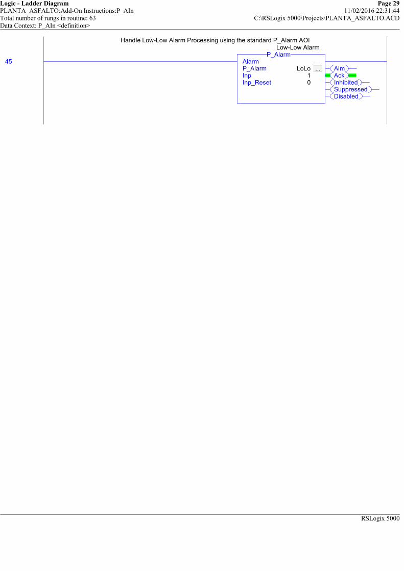
Logic - Ladder Diagram Page 29PLANTA_ASFALTO:Add-On Instructions:P_AIn 11/02/2016 22:31:44Total number of rungs in routine: 63 C:\RSLogix 5000\Projects\PLANTA_ASFALTO.ACDData Context: P_AIn <definition>
RSLogix 5000
Handle Low-Low Alarm Processing using the standard P_Alarm AOI
45AlmAckInhibitedSuppressedDisabled
AlarmP_Alarm LoLo ... Inp 1Inp_Reset 0
P_AlarmLow-Low Alarm
Handle Low-Low Alarm Processing using the standard P_Alarm AOI
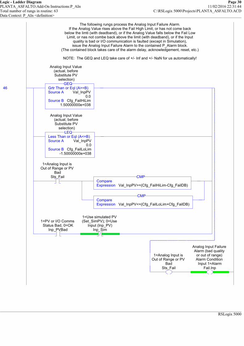
Logic - Ladder Diagram Page 30PLANTA_ASFALTO:Add-On Instructions:P_AIn 11/02/2016 22:31:44Total number of rungs in routine: 63 C:\RSLogix 5000\Projects\PLANTA_ASFALTO.ACDData Context: P_AIn <definition>
RSLogix 5000
The following rungs process the Analog Input Failure Alarm.If the Analog Value rises above the Fail High Limit, or has not come back
below the limti (with deadband), or if the Analog Value falls below the Fail LowLimit, or nas not combe back above the limit (with deadband), or if the Input
quality is bad or I/O communication is faulted (except in Simulation),issue the Analog Input Failure Alarm to the contained P_Alarm block.
(The contained block takes care of the alarm delay, acknowledgement, reset, etc.)
NOTE: The GEQ and LEQ take care of +/- Inf and +/- NaN for us automatically!
46 Grtr Than or Eql (A>=B)Source A Val_InpPV
0.0Source B Cfg_FailHiLim
1.50000000e+038
GEQ
Analog Input Value (actual, before Substitute PV
selection)
Less Than or Eql (A<=B)Source A Val_InpPV
0.0Source B Cfg_FailLoLim
-1.50000000e+038
LEQ
Analog Input Value (actual, before Substitute PV
selection)
1=Analog Input is Out of Range or PV
BadSts_Fail
CompareExpression Val_InpPV>=(Cfg_FailHiLim-Cfg_FailDB)
CMP
CompareExpression Val_InpPV<=(Cfg_FailLoLim+Cfg_FailDB)
CMP
1=PV or I/O Comms Status Bad, 0=OK
Inp_PVBad/
1=Use simulated PV (Set_SimPV); 0=Use
Input (Inp_PV)Inp_Sim
1=Analog Input is Out of Range or PV
BadSts_Fail
Analog Input Failure Alarm (bad quality
or out of range) Alarm Condition
Input 1=AlarmFail.Inp
The following rungs process the Analog Input Failure Alarm.If the Analog Value rises above the Fail High Limit, or has not come back
below the limti (with deadband), or if the Analog Value falls below the Fail LowLimit, or nas not combe back above the limit (with deadband), or if the Input
quality is bad or I/O communication is faulted (except in Simulation),issue the Analog Input Failure Alarm to the contained P_Alarm block.
(The contained block takes care of the alarm delay, acknowledgement, reset, etc.)
NOTE: The GEQ and LEQ take care of +/- Inf and +/- NaN for us automatically!

Logic - Ladder Diagram Page 31PLANTA_ASFALTO:Add-On Instructions:P_AIn 11/02/2016 22:31:45Total number of rungs in routine: 63 C:\RSLogix 5000\Projects\PLANTA_ASFALTO.ACDData Context: P_AIn <definition>
RSLogix 5000
PCmd_FailAck: Command to Acknowledge the Analog Input Failure Alarm
47
Program Command to Acknowldege Analog
Input Failure AlarmPCmd_FailAck
1=Clear Program Commands on receipt
0=Leave SetCfg_PCmdClear
U
Program Command to Acknowldege Analog
Input Failure AlarmPCmd_FailAck
L
Analog Input Failure Alarm (bad quality
or out of range) Program Command to
Acknowledge alarmFail.PCmd_Ack
PCmd_FailAck: Command to Acknowledge the Analog Input Failure Alarm
PCmd_FailInhibit: Program Command to Inhibit the Analog Input Failure Alarm
48
Program Command to Inhibit Analog Input
Failure AlarmPCmd_FailInhibit
1=Clear Program Commands on receipt
0=Leave SetCfg_PCmdClear
U
Program Command to Inhibit Analog Input
Failure AlarmPCmd_FailInhibit
L
Analog Input Failure Alarm (bad quality
or out of range) Program Command to
Inhibit alarm (force Alm to 0)
Fail.PCmd_Inhibit
/
1=Clear Program Commands on receipt
0=Leave SetCfg_PCmdClear
/
Program Command to Inhibit Analog Input
Failure AlarmPCmd_FailInhibit
L
Analog Input Failure Alarm (bad quality
or out of range) Program Command to
Uninhibit alarmFail.PCmd_Uninhibit
PCmd_FailInhibit: Program Command to Inhibit the Analog Input Failure Alarm
PCmd_FailUninhibit: Program Command to Uninhibit the Analog Input Failure Alarm
49
Program Command to Uninhibit Analog
Input Failure AlarmPCmd_FailUninhibit
U
Program Command to Uninhibit Analog
Input Failure AlarmPCmd_FailUninhibit
L
Analog Input Failure Alarm (bad quality
or out of range) Program Command to
Uninhibit alarmFail.PCmd_Uninhibit
PCmd_FailUninhibit: Program Command to Uninhibit the Analog Input Failure Alarm
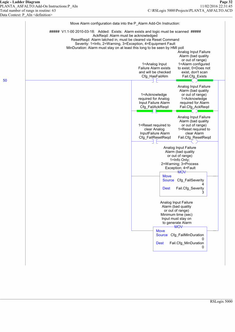
Logic - Ladder Diagram Page 32PLANTA_ASFALTO:Add-On Instructions:P_AIn 11/02/2016 22:31:45Total number of rungs in routine: 63 C:\RSLogix 5000\Projects\PLANTA_ASFALTO.ACDData Context: P_AIn <definition>
RSLogix 5000
Move Alarm configuration data into the P_Alarm Add-On Instruction:
##### V1.1-00 2010-03-18: Added: Exists: Alarm exists and logic must be scanned #####AckReqd: Alarm must be acknowledged
ResetReqd: Alarm latched in, must be cleared via Reset CommandSeverity: 1=Info, 2=Warning, 3=Exception, 4=Equipment Fault
MinDuration: Alarm must stay on at least this long to be seen by HMI poll
50
1=Analog Input Failure Alarm exists and will be checked
Cfg_HasFailAlm
Analog Input Failure Alarm (bad quality
or out of range) 1=Alarm configured to exist, 0=Does not
exist, don't scanFail.Cfg_Exists
1=Acknowledge required for Analog Input Failure AlarmCfg_FailAckReqd
Analog Input Failure Alarm (bad quality
or out of range) 1=Acknowledge
required for AlarmFail.Cfg_AckReqd
1=Reset required to clear Analog
InputFailure AlarmCfg_FailResetReqd
Analog Input Failure Alarm (bad quality
or out of range) 1=Reset required to
clear AlarmFail.Cfg_ResetReqd
MoveSource Cfg_FailSeverity
4Dest Fail.Cfg_Severity
3
MOV
Analog Input Failure Alarm (bad quality
or out of range) 1=Info Only;
2=Warning; 3=Process Exception; 4=Fault
MoveSource Cfg_FailMinDuration
0Dest Fail.Cfg_MinDuration
0
MOV
Analog Input Failure Alarm (bad quality
or out of range) Minimum time (sec) Input must stay on to generate Alarm
Move Alarm configuration data into the P_Alarm Add-On Instruction:
##### V1.1-00 2010-03-18: Added: Exists: Alarm exists and logic must be scanned #####AckReqd: Alarm must be acknowledged
ResetReqd: Alarm latched in, must be cleared via Reset CommandSeverity: 1=Info, 2=Warning, 3=Exception, 4=Equipment Fault
MinDuration: Alarm must stay on at least this long to be seen by HMI poll

Logic - Ladder Diagram Page 33PLANTA_ASFALTO:Add-On Instructions:P_AIn 11/02/2016 22:31:45Total number of rungs in routine: 63 C:\RSLogix 5000\Projects\PLANTA_ASFALTO.ACDData Context: P_AIn <definition>
RSLogix 5000
Handle Analog Input Failure Alarm Processing using the standard P_Alarm AOI
51AlmAckInhibitedSuppressedDisabled
AlarmP_Alarm Fail ... Inp 1Inp_Reset 0
P_Alarm
Analog Input Failure Alarm (bad quality
or out of range)
Handle Analog Input Failure Alarm Processing using the standard P_Alarm AOI

Logic - Ladder Diagram Page 34PLANTA_ASFALTO:Add-On Instructions:P_AIn 11/02/2016 22:31:45Total number of rungs in routine: 63 C:\RSLogix 5000\Projects\PLANTA_ASFALTO.ACDData Context: P_AIn <definition>
RSLogix 5000
============================================================STATUS GENERATION
============================================================
The following rung generates Status bits for this object.
The Mode Status bits are a copy of the internal Mode AOI bits for Oper, Prog, Maint and Prog/Oper Lock.
Remaining status bits are those not covered in the rungs above.
52
Analog Input Mode Selection 1=Mode is
OperatorMode.Sts_Oper
1=Mode is OperatorSts_Oper
Analog Input Mode Selection 1=Mode is
ProgramMode.Sts_Prog
1=Mode is ProgramSts_Prog
Analog Input Mode Selection 1=Mode is
Maintenance (supersedes Ovrd,
Prog, Oper)Mode.Sts_Maint
1=Mode is Maintenance
(supersedes Prog, Oper)
Sts_Maint
Analog Input Mode Selection 1=Program
or Operator has requested Mode Lock
Mode.Sts_ProgOperLock
1=Program or Operator has
requested Mode LockSts_ProgOperLock
Internal flag: Using Substitute PVWrk_SubstPV
1=Using Substitute PV (Input being
overridden)Sts_SubstPV
/
Internal flag: Using Substitute PVWrk_SubstPV
1=Using Input PV (normal)
Sts_InpPV
/
Internal flag: Using Substitute PVWrk_SubstPV
1=Analog Input is Out of Range or PV
BadSts_Fail
Selected PV (Input or Substitute) is Infinite or NaN
Wrk_SelPVInfNaN
1=PV Bad quality or Out of RangeSts_PVBad
1=PV Value Not Reliable, 0=OK
Inp_PVUncertain/
1=Use simulated PV (Set_SimPV); 0=Use
Input (Inp_PV)Inp_Sim
/
Internal flag: Using Substitute PVWrk_SubstPV
1=PV Value is Uncertain (quality)Sts_PVUncertain
============================================================STATUS GENERATION
============================================================
The following rung generates Status bits for this object.
The Mode Status bits are a copy of the internal Mode AOI bits for Oper, Prog, Maint and Prog/Oper Lock.
Remaining status bits are those not covered in the rungs above.
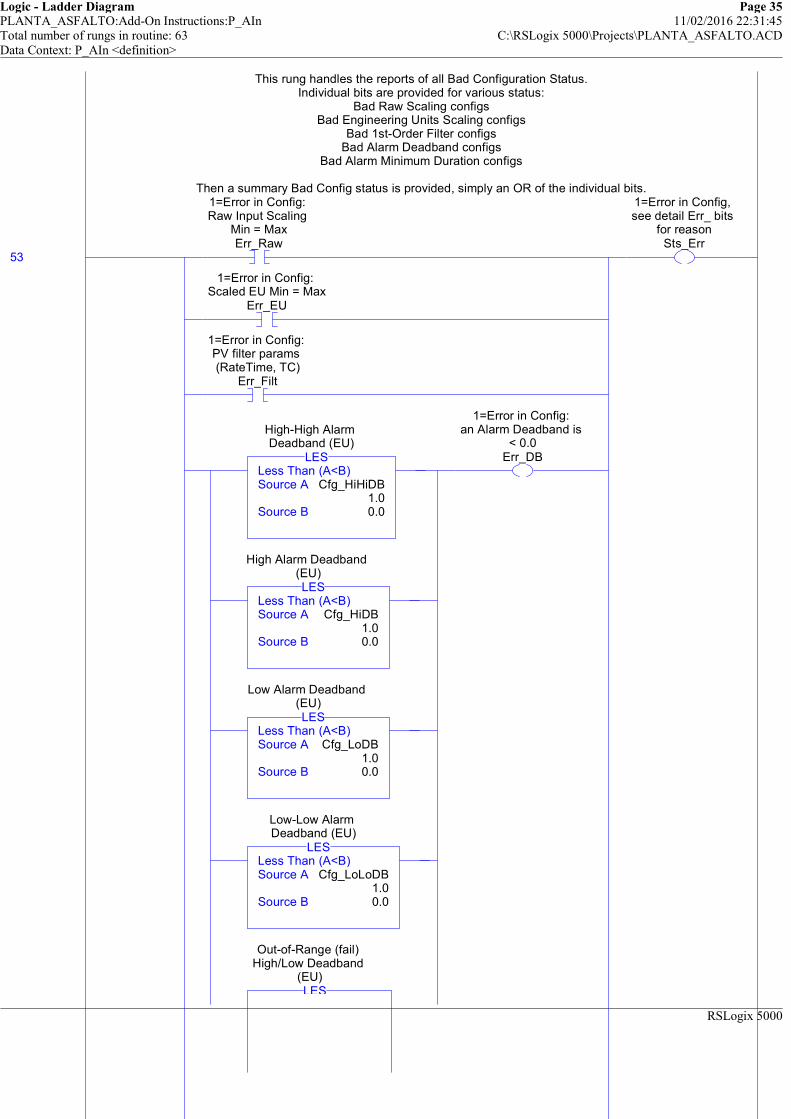
Logic - Ladder Diagram Page 35PLANTA_ASFALTO:Add-On Instructions:P_AIn 11/02/2016 22:31:45Total number of rungs in routine: 63 C:\RSLogix 5000\Projects\PLANTA_ASFALTO.ACDData Context: P_AIn <definition>
RSLogix 5000
This rung handles the reports of all Bad Configuration Status.Individual bits are provided for various status:
Bad Raw Scaling configsBad Engineering Units Scaling configs
Bad 1st-Order Filter configsBad Alarm Deadband configs
Bad Alarm Minimum Duration configs
Then a summary Bad Config status is provided, simply an OR of the individual bits.
53
1=Error in Config: Raw Input Scaling
Min = MaxErr_Raw
1=Error in Config: Scaled EU Min = Max
Err_EU
1=Error in Config: PV filter params (RateTime, TC)
Err_Filt
Less Than (A<B)Source A Cfg_HiHiDB
1.0Source B 0.0
LES
High-High Alarm Deadband (EU)
Less Than (A<B)Source A Cfg_HiDB
1.0Source B 0.0
LES
High Alarm Deadband (EU)
Less Than (A<B)Source A Cfg_LoDB
1.0Source B 0.0
LES
Low Alarm Deadband (EU)
Less Than (A<B)Source A Cfg_LoLoDB
1.0Source B 0.0
LES
Low-Low Alarm Deadband (EU)
LES
Out-of-Range (fail) High/Low Deadband
(EU)
1=Error in Config: an Alarm Deadband is
< 0.0Err_DB
1=Error in Config, see detail Err_ bits
for reasonSts_Err
This rung handles the reports of all Bad Configuration Status.Individual bits are provided for various status:
Bad Raw Scaling configsBad Engineering Units Scaling configs
Bad 1st-Order Filter configsBad Alarm Deadband configs
Bad Alarm Minimum Duration configs
Then a summary Bad Config status is provided, simply an OR of the individual bits.

Logic - Ladder Diagram Page 36PLANTA_ASFALTO:Add-On Instructions:P_AIn 11/02/2016 22:31:45Total number of rungs in routine: 63 C:\RSLogix 5000\Projects\PLANTA_ASFALTO.ACDData Context: P_AIn <definition>
RSLogix 5000
Less Than (A<B)Source A Cfg_FailDB
0.0Source B 0.0
LES
High-High Alarm 1=Error in Config: see detail Err_ bits
for reasonHiHi.Sts_Err
High Alarm 1=Error in Config: see
detail Err_ bits for reason
Hi.Sts_Err
Low Alarm 1=Error in Config: see detail Err_ bits for reason
Lo.Sts_Err
Low-Low Alarm 1=Error in Config: see detail Err_ bits
for reasonLoLo.Sts_Err
Analog Input Failure Alarm (bad quality
or out of range) 1=Error in Config: see detail Err_ bits
for reasonFail.Sts_Err
1=Error in Config: Invalid Alarm Min
Duration or SeverityErr_Alarm

Logic - Ladder Diagram Page 37PLANTA_ASFALTO:Add-On Instructions:P_AIn 11/02/2016 22:31:45Total number of rungs in routine: 63 C:\RSLogix 5000\Projects\PLANTA_ASFALTO.ACDData Context: P_AIn <definition>
RSLogix 5000
Alarm Status bits are a copy of the internal Alarm AOI Status bits.
54
High-High Alarm Alarm output 1=In
AlarmHiHi.Alm
1=Analog Input is in High-High Alarm
Alm_HiHi
High-High Alarm Alarm acknowledged
status: 1=Ack rcvdHiHi.Ack
1=High-High Alarm has been
acknowledgedAck_HiHi
High-High Alarm 1=Alarm has been
Disabled by Maintanance (will
not be sent)HiHi.Disabled
1=High-High Alarm is Disabled (not saved
or sent)Sts_HiHiDisabled
High-High Alarm 1=Alarm has been
Inhibited by Program (will not be sent)
HiHi.Inhibited
1=High-High Alarm is Inhibited by logicSts_HiHiInhibited
High-High Alarm 1=Alarm has been
Suppressed by Operator (not visible on HMI)
HiHi.Suppressed
1=High-High Alarm has been suppressed
(logged only)Sts_HiHiSuppressed
Alarm Status bits are a copy of the internal Alarm AOI Status bits.

Logic - Ladder Diagram Page 38PLANTA_ASFALTO:Add-On Instructions:P_AIn 11/02/2016 22:31:45Total number of rungs in routine: 63 C:\RSLogix 5000\Projects\PLANTA_ASFALTO.ACDData Context: P_AIn <definition>
RSLogix 5000
Alarm Status bits are a copy of the internal Alarm AOI Status bits.
55
High Alarm Alarm output 1=In Alarm
Hi.Alm
1=Analog Input is in High Alarm
Alm_Hi
High Alarm Alarm acknowledged status:
1=Ack rcvdHi.Ack
1=High Alarm has been acknowledged
Ack_Hi
High Alarm 1=Alarm has been Disabled by
Maintanance (will not be sent)Hi.Disabled
1=High Alarm is Disabled (not saved
or sent)Sts_HiDisabled
High Alarm 1=Alarm has been Inhibited
by Program (will not be sent)
Hi.Inhibited
1=High Alarm is Inhibited by logicSts_HiInhibited
High Alarm 1=Alarm has been Suppressed
by Operator (not visible on HMI)Hi.Suppressed
1=High Alarm has been suppressed
(logged only)Sts_HiSuppressed
Alarm Status bits are a copy of the internal Alarm AOI Status bits.
Alarm Status bits are a copy of the internal Alarm AOI Status bits.
56
Low Alarm Alarm output 1=In Alarm
Lo.Alm
1=Analog Input is in Low Alarm
Alm_Lo
Low Alarm Alarm acknowledged status:
1=Ack rcvdLo.Ack
1=Low Alarm has been acknowledged
Ack_Lo
Low Alarm 1=Alarm has been Disabled by
Maintanance (will not be sent)Lo.Disabled
1=Low Alarm is Disabled (not saved
or sent)Sts_LoDisabled
Low Alarm 1=Alarm has been Inhibited
by Program (will not be sent)
Lo.Inhibited
1=Low Alarm is Inhibited by logicSts_LoInhibited
Low Alarm 1=Alarm has been Suppressed
by Operator (not visible on HMI)Lo.Suppressed
1=Low Alarm has been suppressed (logged
only)Sts_LoSuppressed
Alarm Status bits are a copy of the internal Alarm AOI Status bits.

Logic - Ladder Diagram Page 39PLANTA_ASFALTO:Add-On Instructions:P_AIn 11/02/2016 22:31:45Total number of rungs in routine: 63 C:\RSLogix 5000\Projects\PLANTA_ASFALTO.ACDData Context: P_AIn <definition>
RSLogix 5000
Alarm Status bits are a copy of the internal Alarm AOI Status bits.
57
Low-Low Alarm Alarm output 1=In Alarm
LoLo.Alm
1=Analog Input is in Low-Low Alarm
Alm_LoLo
Low-Low Alarm Alarm acknowledged status:
1=Ack rcvdLoLo.Ack
1=Low-Low Alarm has been acknowledged
Ack_LoLo
Low-Low Alarm 1=Alarm has been
Disabled by Maintanance (will
not be sent)LoLo.Disabled
1=Low-Low Alarm is Disabled (not saved
or sent)Sts_LoLoDisabled
Low-Low Alarm 1=Alarm has been
Inhibited by Program (will not be sent)LoLo.Inhibited
1=Low-Low Alarm is Inhibited by logicSts_LoLoInhibited
Low-Low Alarm 1=Alarm has been
Suppressed by Operator (not visible on HMI)
LoLo.Suppressed
1=Low-Low Alarm has been suppressed
(logged only)Sts_LoLoSuppressed
Alarm Status bits are a copy of the internal Alarm AOI Status bits.

Logic - Ladder Diagram Page 40PLANTA_ASFALTO:Add-On Instructions:P_AIn 11/02/2016 22:31:45Total number of rungs in routine: 63 C:\RSLogix 5000\Projects\PLANTA_ASFALTO.ACDData Context: P_AIn <definition>
RSLogix 5000
Alarm Status bits are a copy of the internal Alarm AOI Status bits.
58
Analog Input Failure Alarm (bad quality
or out of range) Alarm output 1=In
AlarmFail.Alm
1=Analog Input Failure Alarm (Bad
or Out of Range)Alm_Fail
Analog Input Failure Alarm (bad quality
or out of range) Alarm acknowledged
status: 1=Ack rcvdFail.Ack
1=Analog Input Failure Alarm has
been acknowledgedAck_Fail
Analog Input Failure Alarm (bad quality
or out of range) 1=Alarm has been
Inhibited by Program (will not be sent)
Fail.Inhibited
1=Analog Input Failure Alarm is inhibited by logicSts_FailInhibited
Analog Input Failure Alarm (bad quality
or out of range) 1=Alarm has been
Disabled by Maintanance (will
not be sent)Fail.Disabled
1=Analog input Failure Alarm is
Disabled (not saved or sent)
Sts_FailDisabled
Analog Input Failure Alarm (bad quality
or out of range) 1=Alarm has been
Suppressed by Operator (not visible on HMI)
Fail.Suppressed
1=Analog Input Failure Alarm has been suppressed
(logged only)Sts_FailSuppressed
Alarm Status bits are a copy of the internal Alarm AOI Status bits.
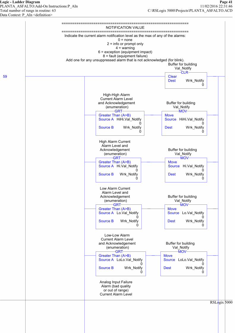
Logic - Ladder Diagram Page 41PLANTA_ASFALTO:Add-On Instructions:P_AIn 11/02/2016 22:31:46Total number of rungs in routine: 63 C:\RSLogix 5000\Projects\PLANTA_ASFALTO.ACDData Context: P_AIn <definition>
RSLogix 5000
============================================================NOTIFICATION VALUE
============================================================Indicate the current alarm notification level as the max of any of the alarms:
0 = none2 = info or prompt only
4 = warning6 = exception (equipment impact)
8 = fault (equipment failure)Add one for any unsuppressed alarm that is not acknowledged (for blink).
59 ClearDest Wrk_Notify
0
CLR
Buffer for building Val_Notify
Greater Than (A>B)Source A HiHi.Val_Notify
0Source B Wrk_Notify
0
GRT
High-High Alarm Current Alarm Level
and Acknowledgement (enumeration)
MoveSource HiHi.Val_Notify
0Dest Wrk_Notify
0
MOV
Buffer for building Val_Notify
Greater Than (A>B)Source A Hi.Val_Notify
0Source B Wrk_Notify
0
GRT
High Alarm Current Alarm Level and
Acknowledgement (enumeration)
MoveSource Hi.Val_Notify
0Dest Wrk_Notify
0
MOV
Buffer for building Val_Notify
Greater Than (A>B)Source A Lo.Val_Notify
0Source B Wrk_Notify
0
GRT
Low Alarm Current Alarm Level and
Acknowledgement (enumeration)
MoveSource Lo.Val_Notify
0Dest Wrk_Notify
0
MOV
Buffer for building Val_Notify
Greater Than (A>B)Source A LoLo.Val_Notify
0Source B Wrk_Notify
0
GRT
Low-Low Alarm Current Alarm Level
and Acknowledgement (enumeration)
MoveSource LoLo.Val_Notify
0Dest Wrk_Notify
0
MOV
Buffer for building Val_Notify
Analog Input Failure Alarm (bad quality
or out of range) Current Alarm Level
============================================================NOTIFICATION VALUE
============================================================Indicate the current alarm notification level as the max of any of the alarms:
0 = none2 = info or prompt only
4 = warning6 = exception (equipment impact)
8 = fault (equipment failure)Add one for any unsuppressed alarm that is not acknowledged (for blink).

Logic - Ladder Diagram Page 42PLANTA_ASFALTO:Add-On Instructions:P_AIn 11/02/2016 22:31:46Total number of rungs in routine: 63 C:\RSLogix 5000\Projects\PLANTA_ASFALTO.ACDData Context: P_AIn <definition>
RSLogix 5000
Greater Than (A>B)Source A Fail.Val_Notify
0Source B Wrk_Notify
0
GRT
Current Alarm Level and Acknowledgement
(enumeration)
MoveSource Fail.Val_Notify
0Dest Wrk_Notify
0
MOV
Buffer for building Val_Notify
High-High Alarm Current Alarm Level
and Acknowledgement (enumeration)
HiHi.Val_Notify.0
High Alarm Current Alarm Level and
Acknowledgement (enumeration)Hi.Val_Notify.0
Low Alarm Current Alarm Level and
Acknowledgement (enumeration)
Lo.Val_Notify.0
Low-Low Alarm Current Alarm Level
and Acknowledgement (enumeration)
LoLo.Val_Notify.0
Analog Input Failure Alarm (bad quality
or out of range) Current Alarm Level
and Acknowledgement (enumeration)
Fail.Val_Notify.0
Buffer for building Val_Notify
Wrk_Notify.0
MoveSource Wrk_Notify
0Dest Val_Notify
0
MOV
Current Alarm Level and Acknowledgement
(enumeration)

Logic - Ladder Diagram Page 43PLANTA_ASFALTO:Add-On Instructions:P_AIn 11/02/2016 22:31:46Total number of rungs in routine: 63 C:\RSLogix 5000\Projects\PLANTA_ASFALTO.ACDData Context: P_AIn <definition>
RSLogix 5000
============================================================COMMAND READIES
============================================================In Maintenance Mode, commands for Substitue PV and Input PV are available
based on the current state of the internal toggle bit.
60
1=Mode is Maintenance
(supersedes Prog, Oper)
Sts_Maint/
1=Disallow selection of Substitute PVCfg_NoSubstPV
/
Internal flag: Using Substitute PVWrk_SubstPV
1=Ready for MCmd_SubstPV
Rdy_SubstPV
Internal flag: Using Substitute PVWrk_SubstPV
1=Ready for MCmd_InpPV
Rdy_InpPV
============================================================COMMAND READIES
============================================================In Maintenance Mode, commands for Substitue PV and Input PV are available
based on the current state of the internal toggle bit.
This object requires a Reset if any of its Alarms requires a Reset.
61
High-High Alarm Ready to receive
OCmd_Reset (enable button)
HiHi.Rdy_Reset
High Alarm Ready to receive OCmd_Reset
(enable button)Hi.Rdy_Reset
Low Alarm Ready to receive OCmd_Reset
(enable button)Lo.Rdy_Reset
Low-Low Alarm Ready to receive
OCmd_Reset (enable button)
LoLo.Rdy_Reset
Analog Input Failure Alarm (bad quality
or out of range) Ready to receive
OCmd_Reset (enable button)
Fail.Rdy_Reset
1=At least one Alarm requires Reset
Rdy_Reset
This object requires a Reset if any of its Alarms requires a Reset.

Logic - Ladder Diagram Page 44PLANTA_ASFALTO:Add-On Instructions:P_AIn 11/02/2016 22:31:46Total number of rungs in routine: 63 C:\RSLogix 5000\Projects\PLANTA_ASFALTO.ACDData Context: P_AIn <definition>
RSLogix 5000
##### V1.1-00 2010-03-18: Added Rung #####
Ready to receive other Operator Settings (OSet_xxx) if tracking is NOT enabled,or we're in Operator or Maintenance Mode.
62 /
1=PSets track OSets in Oper, OSets track PSets in Prog, 0=no
trackingCfg_SetTrack
Analog Input Mode Selection 1=Mode is
OperatorMode.Sts_Oper
Analog Input Mode Selection 1=Mode is
Maintenance (supersedes Ovrd,
Prog, Oper)Mode.Sts_Maint
1=Ready to receive OSets (other than CV) (enables data
entry fields)Rdy_OSet
##### V1.1-00 2010-03-18: Added Rung #####
Ready to receive other Operator Settings (OSet_xxx) if tracking is NOT enabled,or we're in Operator or Maintenance Mode.
(End)

Logic - Ladder Diagram Page 1PLANTA_ASFALTO:Add-On Instructions:P_AOut 11/02/2016 22:32:03Total number of rungs in routine: 55 C:\RSLogix 5000\Projects\PLANTA_ASFALTO.ACDData Context: P_AOut <definition>
RSLogix 5000
============================================================P_AOut : PROCESS -- ANALOG OUTPUT
============================================================Revision 1.1-00 - Release: 2010-03-18
* (33) Fixed output scaling: raw and EU were swapped;* (43, 6) Added Rdy_CV, Rdy_OSet for HMI to animate data entry fields
* Fixed conditions for Sts_BypActive to include Override Mode (if configured);* (54) Includes updated P_Alarm 1.1-00
* (62) Fixed clearing of Ready (Rdy_) bits in EnableInFalse (Y), Prescan (N)Fixed Err_EU and Err_Raw when in Simulation.
============================================================This Instruction controls an Analog Output and provides:
* Program and Operator entry of target CV in Engineering Units* Ramping of Output CV to target at specified Rate of Change (EU/sec)* Scaling of Output CV from Engineering Units to Raw (I/O card) Units
* Monitoring of Interlock conditions which cause output to shed* Configurable shed to HOLD or to configured SAFE value
* Monitoring of I/O communication faults* Alarms for Interlock Trip, I/O Fault
* Operation in Hand, Maintenance, Override, Program and Operator Modes* "Available" status for use by automation logic to know whether Output
can be controlled by other objects.============================================================
POWERUP / INVALID STATE HANDLING============================================================
Mode states are retained through a power cycle.============================================================
MODE PROCESSING============================================================
These rungs handle received Mode Inputs and Commands:
NOTE: Operator Commands for Mode, Alarm are sent directly to the contained P_Mode and P_Alarm AOIs.
Inp_Hand: forward the Hand Input directly to the Mode instruction.
0
1=Select Hand (hardwired) Control
StrategyInp_Hand
Analog Output Mode Selection 1=Select
Hand (typ. hardwired) ModeMode.Inp_Hand
============================================================P_AOut : PROCESS -- ANALOG OUTPUT
============================================================Revision 1.1-00 - Release: 2010-03-18
* (33) Fixed output scaling: raw and EU were swapped;* (43, 6) Added Rdy_CV, Rdy_OSet for HMI to animate data entry fields
* Fixed conditions for Sts_BypActive to include Override Mode (if configured);* (54) Includes updated P_Alarm 1.1-00
* (62) Fixed clearing of Ready (Rdy_) bits in EnableInFalse (Y), Prescan (N)Fixed Err_EU and Err_Raw when in Simulation.
============================================================This Instruction controls an Analog Output and provides:
* Program and Operator entry of target CV in Engineering Units* Ramping of Output CV to target at specified Rate of Change (EU/sec)* Scaling of Output CV from Engineering Units to Raw (I/O card) Units
* Monitoring of Interlock conditions which cause output to shed* Configurable shed to HOLD or to configured SAFE value
* Monitoring of I/O communication faults* Alarms for Interlock Trip, I/O Fault
* Operation in Hand, Maintenance, Override, Program and Operator Modes* "Available" status for use by automation logic to know whether Output
can be controlled by other objects.============================================================
POWERUP / INVALID STATE HANDLING============================================================
Mode states are retained through a power cycle.============================================================
MODE PROCESSING============================================================
These rungs handle received Mode Inputs and Commands:
NOTE: Operator Commands for Mode, Alarm are sent directly to the contained P_Mode and P_Alarm AOIs.
Inp_Hand: forward the Hand Input directly to the Mode instruction.
Inp_Ovrd: forward the Override Input directly to the Mode instruction.
1
1=Select Override control strategy
Inp_Ovrd
Analog Output Mode Selection 1=Select
Override (typ. Process/Safety Interlock) ModeMode.Inp_Ovrd
Inp_Ovrd: forward the Override Input directly to the Mode instruction.

Logic - Ladder Diagram Page 2PLANTA_ASFALTO:Add-On Instructions:P_AOut 11/02/2016 22:32:12Total number of rungs in routine: 55 C:\RSLogix 5000\Projects\PLANTA_ASFALTO.ACDData Context: P_AOut <definition>
RSLogix 5000
PCmd_Acq: Program Command to Acquire ownership
2
Program Command to Acquire ownership
(Oper to Prog)PCmd_Acq
1=Clear Program Commands on receipt
0=Leave SetCfg_PCmdClear
U
Program Command to Acquire ownership
(Oper to Prog)PCmd_Acq
L
Analog Output Mode Selection Program
Command to Acquire Ownership (Oper to
Prog)Mode.PCmd_Acq
/
Program Command to Acquire ownership
(Oper to Prog)PCmd_Acq
/
1=Clear Program Commands on receipt
0=Leave SetCfg_PCmdClear
U
Analog Output Mode Selection Program
Command to Acquire Ownership (Oper to
Prog)Mode.PCmd_Acq
PCmd_Acq: Program Command to Acquire ownership
PCmd_Rel: Program Command to Release ownership (to Oper)
3
Program Command to Release ownership
(Prog to Oper)PCmd_Rel
U
Program Command to Release ownership
(Prog to Oper)PCmd_Rel
L
Analog Output Mode Selection Program
Command to Release Ownership (Prog to
Oper)Mode.PCmd_Rel
PCmd_Rel: Program Command to Release ownership (to Oper)
PCmd_Lock: Program Command to Lock ownership in Prog Mode
4
Program Command to Lock Mode in Prog
PCmd_Lock
1=Clear Program Commands on receipt
0=Leave SetCfg_PCmdClear
U
Program Command to Lock Mode in Prog
PCmd_Lock
L
Analog Output Mode Selection Program
Command to Lock Mode in Prog
Mode.PCmd_Lock
/
Program Command to Lock Mode in Prog
PCmd_Lock/
1=Clear Program Commands on receipt
0=Leave SetCfg_PCmdClear
U
Analog Output Mode Selection Program
Command to Lock Mode in Prog
Mode.PCmd_Lock
PCmd_Lock: Program Command to Lock ownership in Prog Mode
PCmd_Unlock: Program Command to Unlock Mode
5
Program Command to Unlock Mode
PCmd_UnlockU
Program Command to Unlock ModePCmd_Unlock
L
Analog Output Mode Selection Program
Command to Unlock Mode
Mode.PCmd_Unlock
PCmd_Unlock: Program Command to Unlock Mode

Logic - Ladder Diagram Page 3PLANTA_ASFALTO:Add-On Instructions:P_AOut 11/02/2016 22:32:12Total number of rungs in routine: 55 C:\RSLogix 5000\Projects\PLANTA_ASFALTO.ACDData Context: P_AOut <definition>
RSLogix 5000
Handle Mode Selection using the standard P_Mode AOI
6
1=Clear Program Commands on receipt
0=Leave SetCfg_PCmdClear
Analog Output Mode Selection 1=Clear
Program Command on receipt; 0=Use Level-based
(maintained) PCmdsMode.Cfg_PCmdClear
Sts_HandSts_MaintSts_OvrdSts_ProgSts_OperSts_ProgOperLock
ModeP_Mode Mode ... Inp_Hand 0Inp_Ovrd 0
P_Mode
Analog Output Mode Selection
Handle Mode Selection using the standard P_Mode AOI
This rung handles simple First-Come First-Served Ownership Arbitration.If a requestor supplies a non-zero Owner ID and the current owner is NONE (zero),
Ownership is assigned to the requesting ID. When that requestor sets the Owner ID backto zero, Ownership is relinquished back to NONE.
7 EqualSource A PSet_Owner
0Source B 0
EQU
Program Owner Request ID
(non-zero) or Release (zero)
Not EqualSource A PSet_Owner
0Source B 0
NEQ
Program Owner Request ID
(non-zero) or Release (zero)
EqualSource A Val_Owner
0Source B 0
EQU
Current Object Owner ID (0=not owned)
MoveSource PSet_Owner
0Dest Val_Owner
0
MOV
Current Object Owner ID (0=not owned)
This rung handles simple First-Come First-Served Ownership Arbitration.If a requestor supplies a non-zero Owner ID and the current owner is NONE (zero),
Ownership is assigned to the requesting ID. When that requestor sets the Owner ID backto zero, Ownership is relinquished back to NONE.
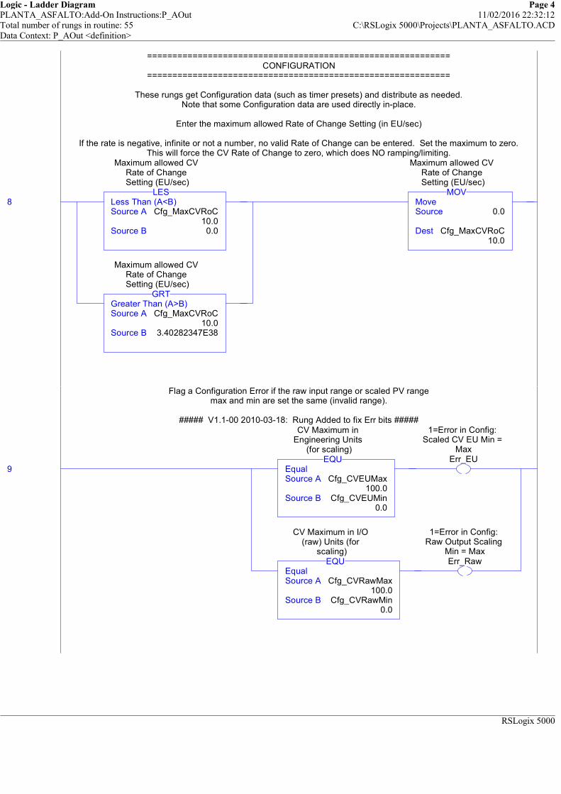
Logic - Ladder Diagram Page 4PLANTA_ASFALTO:Add-On Instructions:P_AOut 11/02/2016 22:32:12Total number of rungs in routine: 55 C:\RSLogix 5000\Projects\PLANTA_ASFALTO.ACDData Context: P_AOut <definition>
RSLogix 5000
============================================================CONFIGURATION
============================================================
These rungs get Configuration data (such as timer presets) and distribute as needed.Note that some Configuration data are used directly in-place.
Enter the maximum allowed Rate of Change Setting (in EU/sec)
If the rate is negative, infinite or not a number, no valid Rate of Change can be entered. Set the maximum to zero.This will force the CV Rate of Change to zero, which does NO ramping/limiting.
8 Less Than (A<B)Source A Cfg_MaxCVRoC
10.0Source B 0.0
LES
Maximum allowed CV Rate of Change Setting (EU/sec)
Greater Than (A>B)Source A Cfg_MaxCVRoC
10.0Source B 3.40282347E38
GRT
Maximum allowed CV Rate of Change Setting (EU/sec)
MoveSource 0.0
Dest Cfg_MaxCVRoC10.0
MOV
Maximum allowed CV Rate of Change Setting (EU/sec)
============================================================CONFIGURATION
============================================================
These rungs get Configuration data (such as timer presets) and distribute as needed.Note that some Configuration data are used directly in-place.
Enter the maximum allowed Rate of Change Setting (in EU/sec)
If the rate is negative, infinite or not a number, no valid Rate of Change can be entered. Set the maximum to zero.This will force the CV Rate of Change to zero, which does NO ramping/limiting.
Flag a Configuration Error if the raw input range or scaled PV rangemax and min are set the same (invalid range).
##### V1.1-00 2010-03-18: Rung Added to fix Err bits #####
9 EqualSource A Cfg_CVEUMax
100.0Source B Cfg_CVEUMin
0.0
EQU
CV Maximum in Engineering Units
(for scaling)
1=Error in Config: Scaled CV EU Min =
MaxErr_EU
EqualSource A Cfg_CVRawMax
100.0Source B Cfg_CVRawMin
0.0
EQU
CV Maximum in I/O (raw) Units (for
scaling)
1=Error in Config: Raw Output Scaling
Min = MaxErr_Raw
Flag a Configuration Error if the raw input range or scaled PV rangemax and min are set the same (invalid range).
##### V1.1-00 2010-03-18: Rung Added to fix Err bits #####
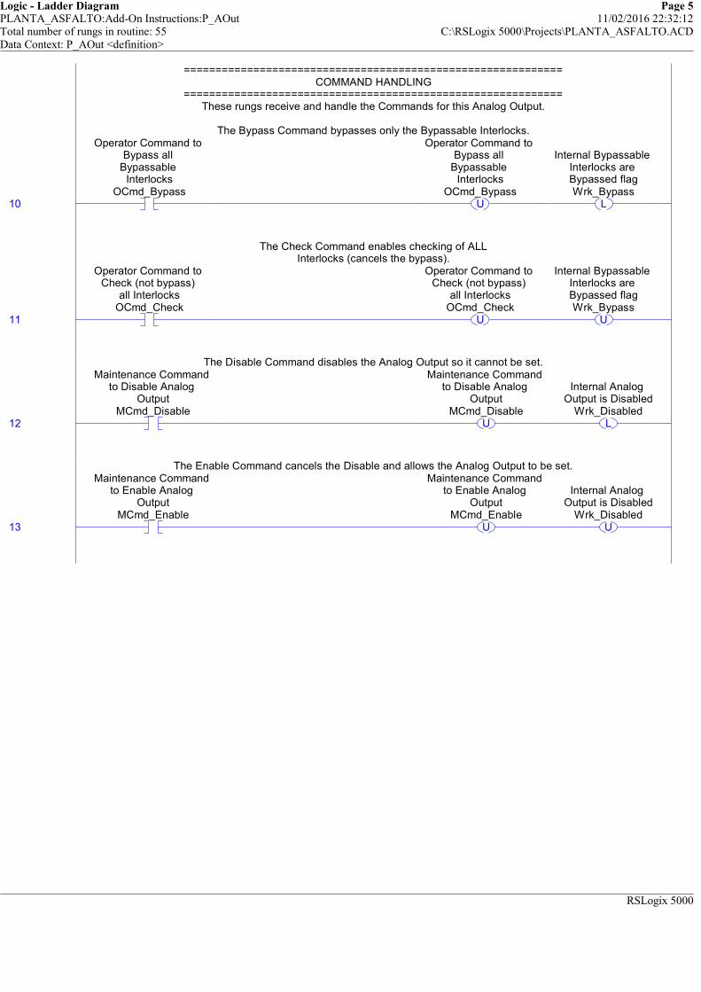
Logic - Ladder Diagram Page 5PLANTA_ASFALTO:Add-On Instructions:P_AOut 11/02/2016 22:32:12Total number of rungs in routine: 55 C:\RSLogix 5000\Projects\PLANTA_ASFALTO.ACDData Context: P_AOut <definition>
RSLogix 5000
============================================================COMMAND HANDLING
============================================================These rungs receive and handle the Commands for this Analog Output.
The Bypass Command bypasses only the Bypassable Interlocks.
10
Operator Command to Bypass all
Bypassable Interlocks
OCmd_BypassU
Operator Command to Bypass all
Bypassable Interlocks
OCmd_BypassL
Internal Bypassable Interlocks are Bypassed flagWrk_Bypass
============================================================COMMAND HANDLING
============================================================These rungs receive and handle the Commands for this Analog Output.
The Bypass Command bypasses only the Bypassable Interlocks.
The Check Command enables checking of ALLInterlocks (cancels the bypass).
11
Operator Command to Check (not bypass)
all InterlocksOCmd_Check
U
Operator Command to Check (not bypass)
all InterlocksOCmd_Check
U
Internal Bypassable Interlocks are Bypassed flagWrk_Bypass
The Check Command enables checking of ALLInterlocks (cancels the bypass).
The Disable Command disables the Analog Output so it cannot be set.
12
Maintenance Command to Disable Analog
OutputMCmd_Disable
U
Maintenance Command to Disable Analog
OutputMCmd_Disable
L
Internal Analog Output is Disabled
Wrk_Disabled
The Disable Command disables the Analog Output so it cannot be set.
The Enable Command cancels the Disable and allows the Analog Output to be set.
13
Maintenance Command to Enable Analog
OutputMCmd_Enable
U
Maintenance Command to Enable Analog
OutputMCmd_Enable
U
Internal Analog Output is Disabled
Wrk_Disabled
The Enable Command cancels the Disable and allows the Analog Output to be set.

Logic - Ladder Diagram Page 6PLANTA_ASFALTO:Add-On Instructions:P_AOut 11/02/2016 22:32:12Total number of rungs in routine: 55 C:\RSLogix 5000\Projects\PLANTA_ASFALTO.ACDData Context: P_AOut <definition>
RSLogix 5000
============================================================SETTINGS PROCESSING
============================================================This rung handles received Settings:
Limit the Program and Operator CV Settings to the hard limits, regardless of Mode(in case tracking is off....).
When the Mode is Program, use the Program Settings for the CV and Rate of Change Limit..When the Mode is Operator or Maintenance, use the Operator Settings.
When the Mode is Override, use the Override CV input for the CV.
14 Greater Than (A>B)Source A PSet_CV
0.0Source B Cfg_MaxCV
100.0
GRT
Program Setting of Controlled Variable
(output) (in EU)
MoveSource Cfg_MaxCV
100.0Dest PSet_CV
0.0
MOV
Program Setting of Controlled Variable
(output) (in EU)
Less Than (A<B)Source A PSet_CV
0.0Source B Cfg_MinCV
0.0
LES
Program Setting of Controlled Variable
(output) (in EU)
MoveSource Cfg_MinCV
0.0Dest PSet_CV
0.0
MOV
Program Setting of Controlled Variable
(output) (in EU)
/
Analog Output Mode Selection 1=Mode is
Maintenance (supersedes Ovrd,
Prog, Oper)Mode.Sts_Maint
/
Analog Output Mode Selection 1=Mode is Hand (supersedes Maint, Ovrd, Prog,
Oper)Mode.Sts_Hand
Greater Than (A>B)Source A OSet_CV
0.0Source B Cfg_MaxCV
100.0
GRT
Operator Setting of Controlled Variable
(output) (in EU)
MoveSource Cfg_MaxCV
100.0Dest OSet_CV
0.0
MOV
Operator Setting of Controlled Variable
(output) (in EU)
Less Than (A<B)Source A OSet_CV
0.0Source B Cfg_MinCV
0.0
LES
Operator Setting of Controlled Variable
(output) (in EU)
MoveSource Cfg_MinCV
0.0Dest OSet_CV
0.0
MOV
Operator Setting of Controlled Variable
(output) (in EU)
Analog Output Mode Selection 1=Mode is
ProgramMode.Sts_Prog
MoveMOV
Working copy of Speed Reference (for
limiting)
============================================================SETTINGS PROCESSING
============================================================This rung handles received Settings:
Limit the Program and Operator CV Settings to the hard limits, regardless of Mode(in case tracking is off....).
When the Mode is Program, use the Program Settings for the CV and Rate of Change Limit..When the Mode is Operator or Maintenance, use the Operator Settings.
When the Mode is Override, use the Override CV input for the CV.
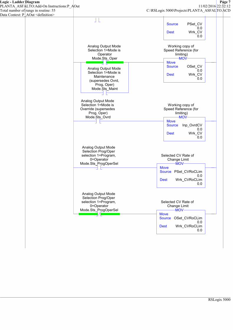
Logic - Ladder Diagram Page 7PLANTA_ASFALTO:Add-On Instructions:P_AOut 11/02/2016 22:32:12Total number of rungs in routine: 55 C:\RSLogix 5000\Projects\PLANTA_ASFALTO.ACDData Context: P_AOut <definition>
RSLogix 5000
MoveSource PSet_CV
0.0Dest Wrk_CV
0.0
Analog Output Mode Selection 1=Mode is
OperatorMode.Sts_Oper
Analog Output Mode Selection 1=Mode is
Maintenance (supersedes Ovrd,
Prog, Oper)Mode.Sts_Maint
MoveSource OSet_CV
0.0Dest Wrk_CV
0.0
MOV
Working copy of Speed Reference (for
limiting)
Analog Output Mode Selection 1=Mode is Override (supersedes
Prog, Oper)Mode.Sts_Ovrd
MoveSource Inp_OvrdCV
0.0Dest Wrk_CV
0.0
MOV
Working copy of Speed Reference (for
limiting)
Analog Output Mode Selection Prog/Oper selection 1=Program,
0=OperatorMode.Sts_ProgOperSel
MoveSource PSet_CVRoCLim
0.0Dest Wrk_CVRoCLim
0.0
MOV
Selected CV Rate of Change Limit
/
Analog Output Mode Selection Prog/Oper selection 1=Program,
0=OperatorMode.Sts_ProgOperSel
MoveSource OSet_CVRoCLim
0.0Dest Wrk_CVRoCLim
0.0
MOV
Selected CV Rate of Change Limit

Logic - Ladder Diagram Page 8PLANTA_ASFALTO:Add-On Instructions:P_AOut 11/02/2016 22:32:12Total number of rungs in routine: 55 C:\RSLogix 5000\Projects\PLANTA_ASFALTO.ACDData Context: P_AOut <definition>
RSLogix 5000
Always limit the entered Rate of Change Limit to be between 0.0 and the configured Maximum.
15 Greater Than (A>B)Source A Wrk_CVRoCLim
0.0Source B Cfg_MaxCVRoC
10.0
GRT
Selected CV Rate of Change Limit
MoveSource Cfg_MaxCVRoC
10.0Dest Wrk_CVRoCLim
0.0
MOV
Selected CV Rate of Change Limit
Less Than (A<B)Source A Wrk_CVRoCLim
0.0Source B 0.0
LES
Selected CV Rate of Change Limit
ClearDest Wrk_CVRoCLim
0.0
CLR
Selected CV Rate of Change Limit
Always limit the entered Rate of Change Limit to be between 0.0 and the configured Maximum.

Logic - Ladder Diagram Page 9PLANTA_ASFALTO:Add-On Instructions:P_AOut 11/02/2016 22:32:12Total number of rungs in routine: 55 C:\RSLogix 5000\Projects\PLANTA_ASFALTO.ACDData Context: P_AOut <definition>
RSLogix 5000
If Interlocks are not OK (non-bypassable always checked, bypassable checked if not bypassed(bypassables not checked in Maintenance Mode, or in Override Mode if Override ignores bypassable interlocks...),
or if there is an I/O Fault, either HOLD the CV or SHED it to the configured Interlock CV,depending on the state of the Shed/Hold configuration.
We don't want the Interlock Trip alarm occuring if Hand or Disabled is going to win down below....
16 /
1=Non-Bypassable Interlocks OK,
Analog Output can be set
Inp_NBIntlkOK
/
1=Interlocks OK, Analog Output can be
setInp_IntlkOK
/
Internal Bypassable Interlocks are Bypassed flagWrk_Bypass
/
Analog Output Mode Selection 1=Mode is
Maintenance (supersedes Ovrd,
Prog, Oper)Mode.Sts_Maint
/
Analog Output Mode Selection 1=Mode is
Override (supersedes Prog, Oper)
Mode.Sts_Ovrd
/
1=Override ignores Bypassable Intlk; 0=always use Intlk
Cfg_OvrdIntlk
Input Communication Status 0=OK, 1=fail
Inp_IOFault/
1=I/O are being simulated, set output CV to 0, ignore I/O Fault
Inp_Sim/
Analog Output Mode Selection 1=Mode is
Maintenance (supersedes Ovrd,
Prog, Oper)Mode.Sts_Maint
/
Analog Output Mode Selection 1=Mode is Hand (supersedes Maint, Ovrd, Prog,
Oper)Mode.Sts_Hand
/
Internal Analog Output is Disabled
Wrk_Disabled
/
1=Hold Output on Interlock, 0=Go to
Cfg_IntlkCVCfg_ShedHold
MoveSource Cfg_IntlkCV
0.0Dest Wrk_CV
0.0
MOV
Working copy of Speed Reference (for
limiting)
1=Hold Output on Interlock, 0=Go to
Cfg_IntlkCVCfg_ShedHold
MoveSource Wrk_CVSet
0.0Dest Wrk_CV
0.0
MOV
Working copy of Speed Reference (for
limiting)
1=Hold Output on 1=Interlock Not OK
If Interlocks are not OK (non-bypassable always checked, bypassable checked if not bypassed(bypassables not checked in Maintenance Mode, or in Override Mode if Override ignores bypassable interlocks...),
or if there is an I/O Fault, either HOLD the CV or SHED it to the configured Interlock CV,depending on the state of the Shed/Hold configuration.
We don't want the Interlock Trip alarm occuring if Hand or Disabled is going to win down below....

Logic - Ladder Diagram Page 10PLANTA_ASFALTO:Add-On Instructions:P_AOut 11/02/2016 22:32:12Total number of rungs in routine: 55 C:\RSLogix 5000\Projects\PLANTA_ASFALTO.ACDData Context: P_AOut <definition>
RSLogix 5000
ONS
Interlock Tripped This Scan
Wrk_IntlkTripONS
1=Hold Output on Interlock, 0=Go to
Cfg_IntlkCVCfg_ShedHold
/
1=Hold Output on Interlock, 0=Go to
Cfg_IntlkCVCfg_ShedHold
Not EqualSource A Wrk_CVSet
0.0Source B Wrk_CV
0.0
NEQ
Final selected CV to feed to RoC Limiter
L
1=Interlock Not OK Tripped active Analog OutputWrk_IntlkTrip
In HAND mode, set the CV to match the tieback from the downstream block.
17
Analog Output Mode Selection 1=Mode is Hand (supersedes Maint, Ovrd, Prog,
Oper)Mode.Sts_Hand
MoveSource Inp_Tieback
0.0Dest Wrk_CV
0.0
MOV
Working copy of Speed Reference (for
limiting)
In HAND mode, set the CV to match the tieback from the downstream block.
If the Analog Output is DISABLED, set the CV to the configured Interlock ("safe") CV.
18
Internal Analog Output is Disabled
Wrk_DisabledMoveSource Cfg_IntlkCV
0.0Dest Wrk_CV
0.0
MOV
Working copy of Speed Reference (for
limiting)
If the Analog Output is DISABLED, set the CV to the configured Interlock ("safe") CV.
After all that selecting, copy the final result to a holding register. (We needed it above to dothe HOLD function on Interlock!)
This is where the CV will be when ramping (if any) is done.
19 MoveSource Wrk_CV
0.0Dest Wrk_CVSet
0.0
MOV
Final selected CV to feed to RoC Limiter
After all that selecting, copy the final result to a holding register. (We needed it above to dothe HOLD function on Interlock!)
This is where the CV will be when ramping (if any) is done.

Logic - Ladder Diagram Page 11PLANTA_ASFALTO:Add-On Instructions:P_AOut 11/02/2016 22:32:12Total number of rungs in routine: 55 C:\RSLogix 5000\Projects\PLANTA_ASFALTO.ACDData Context: P_AOut <definition>
RSLogix 5000
This rung determines whether the selected Analog Output CV is +/- Infinity or +/- NotANumber.In either case, the value cannot be passed into the rate limiter calculation or to the final output.
Instead, perform the designated SHED action: hold last output or shed to the Interlock CV.
20 Copy FileSource Wrk_CVSetDest Wrk_SelCVDINTLength 1
COP
Selected CV check for Infinite or Non
A Number
Mask EqualSource Wrk_SelCVDINT
2#0000_0000_0000_0000_0000_0000_0000_0000Mask 16#7F80_0000
Compare 16#7F80_0000
MEQ
Selected CV check for Infinite or Non
A Number
/
1=Hold Output on Interlock, 0=Go to
Cfg_IntlkCVCfg_ShedHold
MoveSource Cfg_IntlkCV
0.0Dest Wrk_CVSet
0.0
MOV
Final selected CV to feed to RoC Limiter
1=Hold Output on Interlock, 0=Go to
Cfg_IntlkCVCfg_ShedHold
MoveSource Wrk_CVOut
0.0Dest Wrk_CVSet
0.0
MOV
Final selected CV to feed to RoC Limiter
This rung determines whether the selected Analog Output CV is +/- Infinity or +/- NotANumber.In either case, the value cannot be passed into the rate limiter calculation or to the final output.
Instead, perform the designated SHED action: hold last output or shed to the Interlock CV.

Logic - Ladder Diagram Page 12PLANTA_ASFALTO:Add-On Instructions:P_AOut 11/02/2016 22:32:12Total number of rungs in routine: 55 C:\RSLogix 5000\Projects\PLANTA_ASFALTO.ACDData Context: P_AOut <definition>
RSLogix 5000
In preparation for rate limiting the CV, this rungdetermines the time since the previous scan, using a non-stop TON timer.
When we get here, we read the accumulator (in milliseconds, sodivide by 1000.0 to get seconds), then clear the accumulator. Next scan the accumulator will have
incremented up to the number of milliseconds since last scan. (Works for scan times up to 2 million seconds.....)
21 MoveSource 2147483647
Dest Wrk_ScanT.PRE2147483647
MOV
Scan Timer (milliseconds, always runs)
EN
DN
Timer On DelayTimer Wrk_ScanTPreset 2147483647Accum 0
TON
Scan Timer (milliseconds, always runs)
DivideSource A Wrk_ScanT.ACC
0Source B 1000.0
Dest Wrk_ScanTime0.0
DIV
Seconds since previous scan
ClearDest Wrk_ScanT.ACC
0
CLR
Scan Timer (milliseconds, always runs)
In preparation for rate limiting the CV, this rungdetermines the time since the previous scan, using a non-stop TON timer.
When we get here, we read the accumulator (in milliseconds, sodivide by 1000.0 to get seconds), then clear the accumulator. Next scan the accumulator will have
incremented up to the number of milliseconds since last scan. (Works for scan times up to 2 million seconds.....)
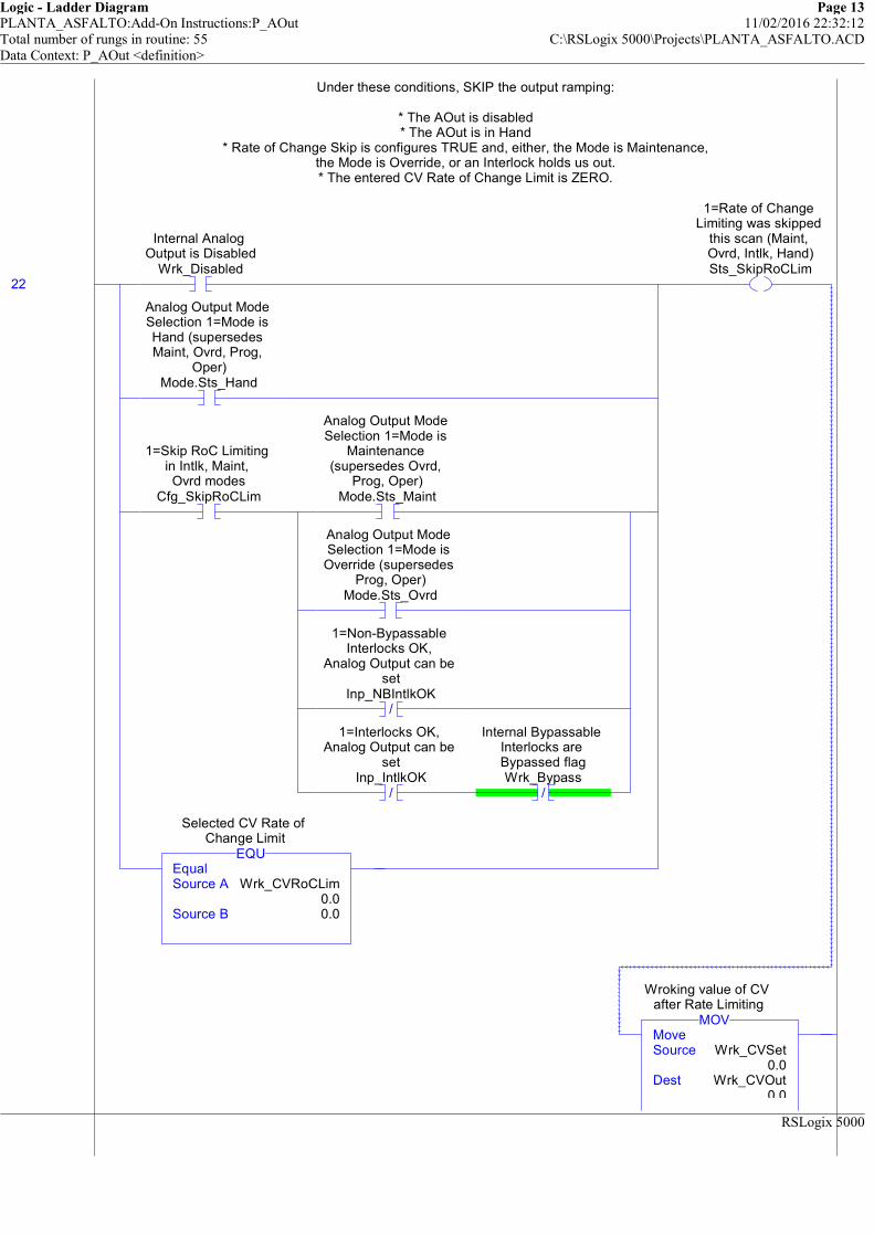
Logic - Ladder Diagram Page 13PLANTA_ASFALTO:Add-On Instructions:P_AOut 11/02/2016 22:32:12Total number of rungs in routine: 55 C:\RSLogix 5000\Projects\PLANTA_ASFALTO.ACDData Context: P_AOut <definition>
RSLogix 5000
Under these conditions, SKIP the output ramping:
* The AOut is disabled* The AOut is in Hand
* Rate of Change Skip is configures TRUE and, either, the Mode is Maintenance,the Mode is Override, or an Interlock holds us out.* The entered CV Rate of Change Limit is ZERO.
22
Internal Analog Output is Disabled
Wrk_Disabled
Analog Output Mode Selection 1=Mode is Hand (supersedes Maint, Ovrd, Prog,
Oper)Mode.Sts_Hand
1=Skip RoC Limiting in Intlk, Maint, Ovrd modes
Cfg_SkipRoCLim
Analog Output Mode Selection 1=Mode is
Maintenance (supersedes Ovrd,
Prog, Oper)Mode.Sts_Maint
Analog Output Mode Selection 1=Mode is Override (supersedes
Prog, Oper)Mode.Sts_Ovrd
/
1=Non-Bypassable Interlocks OK,
Analog Output can be set
Inp_NBIntlkOK
/
1=Interlocks OK, Analog Output can be
setInp_IntlkOK
/
Internal Bypassable Interlocks are Bypassed flagWrk_Bypass
EqualSource A Wrk_CVRoCLim
0.0Source B 0.0
EQU
Selected CV Rate of Change Limit
1=Rate of Change Limiting was skipped
this scan (Maint, Ovrd, Intlk, Hand)Sts_SkipRoCLim
MoveSource Wrk_CVSet
0.0Dest Wrk_CVOut
0.0
MOV
Wroking value of CV after Rate Limiting
Under these conditions, SKIP the output ramping:
* The AOut is disabled* The AOut is in Hand
* Rate of Change Skip is configures TRUE and, either, the Mode is Maintenance,the Mode is Override, or an Interlock holds us out.* The entered CV Rate of Change Limit is ZERO.
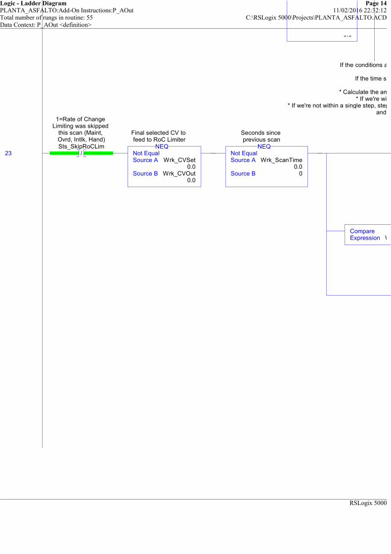
Logic - Ladder Diagram Page 14PLANTA_ASFALTO:Add-On Instructions:P_AOut 11/02/2016 22:32:12Total number of rungs in routine: 55 C:\RSLogix 5000\Projects\PLANTA_ASFALTO.ACDData Context: P_AOut <definition>
RSLogix 5000
0.0
If the conditions above are NOT TRUE, do the rate limiting:
If the time since the previous scan is not ZERO:
* Calculate the amount to step this scan toward the final CV* If we're within a single setp, go to the final CV
* If we're not within a single step, step one step closer (up or down, whichever way we need to go)and show the "Ramping" status.
23 /
1=Rate of Change Limiting was skipped
this scan (Maint, Ovrd, Intlk, Hand)Sts_SkipRoCLim
Not EqualSource A Wrk_CVSet
0.0Source B Wrk_CVOut
0.0
NEQ
Final selected CV to feed to RoC Limiter
Not EqualSource A Wrk_ScanTime
0.0Source B 0
NEQ
Seconds since previous scan
CompareExpression Wrk_CVOut<=(Wrk_CVSet+Wrk_Step)
If the conditions above are NOT TRUE, do the rate limiting:
If the time since the previous scan is not ZERO:
* Calculate the amount to step this scan toward the final CV* If we're within a single setp, go to the final CV
* If we're not within a single step, step one step closer (up or down, whichever way we need to go)and show the "Ramping" status.

Logic - Ladder Diagram Page 15PLANTA_ASFALTO:Add-On Instructions:P_AOut 11/02/2016 22:32:12Total number of rungs in routine: 55 C:\RSLogix 5000\Projects\PLANTA_ASFALTO.ACDData Context: P_AOut <definition>
RSLogix 5000
If the conditions above are NOT TRUE, do the rate limiting:
If the time since the previous scan is not ZERO:
* Calculate the amount to step this scan toward the final CV* If we're within a single setp, go to the final CV
* If we're not within a single step, step one step closer (up or down, whichever way we need to go)and show the "Ramping" status.
MultiplySource A Wrk_CVRoCLim
Source B Wrk_ScanTime
Dest
MUL
Amount to change CVOut this scan for
rate limiting
Wrk_CVOut<=(Wrk_CVSet+Wrk_Step)
CMPCompareExpression Wrk_CVOut>=(Wrk_CVSet-Wrk_Step)
CMPMoveSource
Dest
MOV
Wroking value of CV after Rate Limiting
CompareExpression Wrk_CVOut>(Wrk_CVSet+Wrk_Step)
CMPSubtractSource A Wrk_CVOut
0.0Source B Wrk_Step
0.0Dest Wrk_CVOut
0.0
SUB
Wroking value of CV after Rate Limiting
CompareExpression Wrk_CVOut<=(Wrk_CVSet-Wrk_Step)
CMPAddSource A Wrk_CVOut
0.0Source B Wrk_Step
0.0Dest Wrk_CVOut
0.0
ADD
Wroking value of CV after Rate Limiting
1=CV is ramping to
If the conditions above are NOT TRUE, do the rate limiting:
If the time since the previous scan is not ZERO:
* Calculate the amount to step this scan toward the final CV* If we're within a single setp, go to the final CV
* If we're not within a single step, step one step closer (up or down, whichever way we need to go)and show the "Ramping" status.
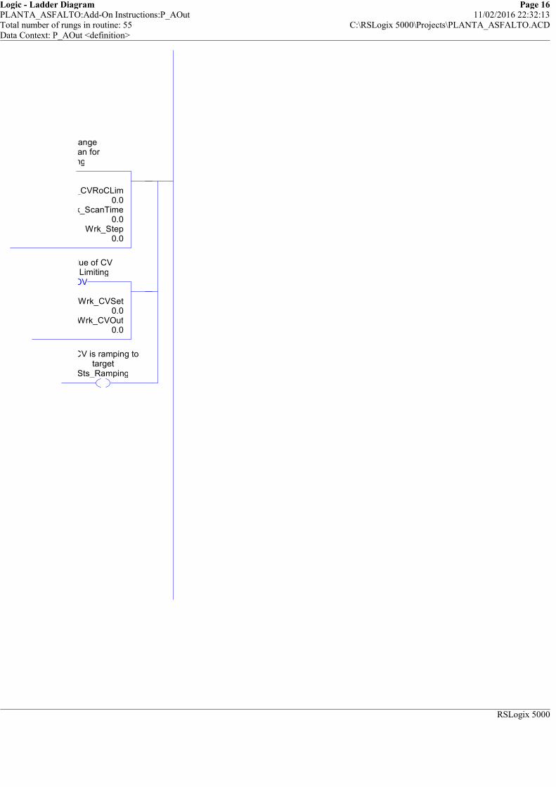
Logic - Ladder Diagram Page 16PLANTA_ASFALTO:Add-On Instructions:P_AOut 11/02/2016 22:32:13Total number of rungs in routine: 55 C:\RSLogix 5000\Projects\PLANTA_ASFALTO.ACDData Context: P_AOut <definition>
RSLogix 5000
Wrk_CVRoCLim0.0
Wrk_ScanTime0.0
Wrk_Step0.0
Amount to change CVOut this scan for
rate limiting
Wrk_CVSet0.0
Wrk_CVOut0.0
MOV
Wroking value of CV after Rate Limiting
1=CV is ramping to target
Sts_Ramping

Logic - Ladder Diagram Page 17PLANTA_ASFALTO:Add-On Instructions:P_AOut 11/02/2016 22:32:13Total number of rungs in routine: 55 C:\RSLogix 5000\Projects\PLANTA_ASFALTO.ACDData Context: P_AOut <definition>
RSLogix 5000
============================================================OUTPUT GENERATION
============================================================This rung generates the instruction Output
If not in simulation, scale the generated Wrk_CVOut to Raw Units in Out_CVIf in Simulation, set Out_CV to zero.
##### V1.1-00 2010-03-18: Modified Rung #####Ffixed scaling CPT -- previously, raw and EU were swapped. Fixed Err_EU and Err_Raw.
24 /
1=I/O are being simulated, set output CV to 0, ignore I/O Fault
Inp_Sim/
1=Error in Config: Scaled CV EU Min =
MaxErr_EU
/
1=Error in Config: Raw Output Scaling
Min = MaxErr_Raw
ComputeDest
Expression (Wrk_CVOut-Cfg_CVEUMin)*(Cfg_CVRawMax-Cfg_CVRawMin)/(Cfg_CVEUMax-Cfg_CVEUMin)+Cfg_CVRawMin
1=Error in Config: Scaled CV EU Min =
MaxErr_EU
1=Error in Config: Raw Output Scaling
Min = MaxErr_Raw
1=I/O are being simulated, set output CV to 0, ignore I/O Fault
Inp_Sim
============================================================OUTPUT GENERATION
============================================================This rung generates the instruction Output
If not in simulation, scale the generated Wrk_CVOut to Raw Units in Out_CVIf in Simulation, set Out_CV to zero.
##### V1.1-00 2010-03-18: Modified Rung #####Ffixed scaling CPT -- previously, raw and EU were swapped. Fixed Err_EU and Err_Raw.
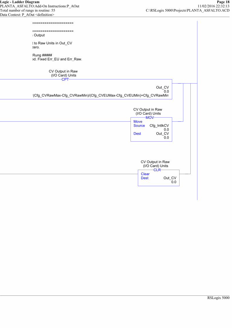
Logic - Ladder Diagram Page 18PLANTA_ASFALTO:Add-On Instructions:P_AOut 11/02/2016 22:32:13Total number of rungs in routine: 55 C:\RSLogix 5000\Projects\PLANTA_ASFALTO.ACDData Context: P_AOut <definition>
RSLogix 5000
============================================================
============================================================This rung generates the instruction Output
If not in simulation, scale the generated Wrk_CVOut to Raw Units in Out_CVIf in Simulation, set Out_CV to zero.
##### V1.1-00 2010-03-18: Modified Rung #####Ffixed scaling CPT -- previously, raw and EU were swapped. Fixed Err_EU and Err_Raw.
Out_CV0.0
(Wrk_CVOut-Cfg_CVEUMin)*(Cfg_CVRawMax-Cfg_CVRawMin)/(Cfg_CVEUMax-Cfg_CVEUMin)+Cfg_CVRawMin
CPT
CV Output in Raw (I/O Card) Units
MoveSource Cfg_IntlkCV
0.0Dest Out_CV
0.0
MOV
CV Output in Raw (I/O Card) Units
ClearDest Out_CV
0.0
CLR
CV Output in Raw (I/O Card) Units
============================================================
============================================================This rung generates the instruction Output
If not in simulation, scale the generated Wrk_CVOut to Raw Units in Out_CVIf in Simulation, set Out_CV to zero.
##### V1.1-00 2010-03-18: Modified Rung #####Ffixed scaling CPT -- previously, raw and EU were swapped. Fixed Err_EU and Err_Raw.
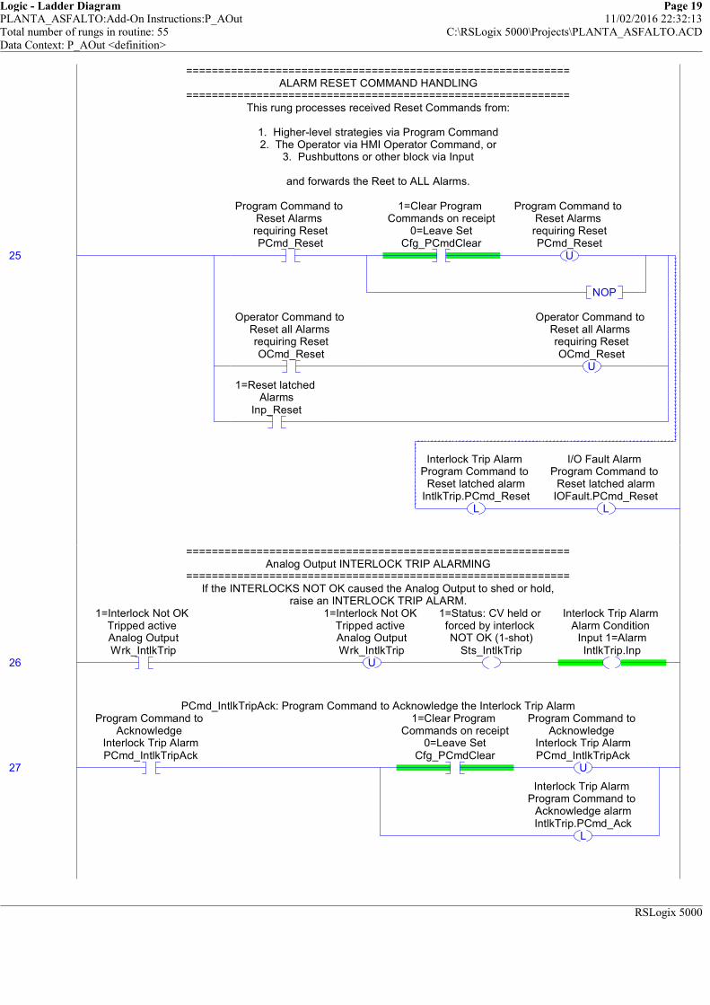
Logic - Ladder Diagram Page 19PLANTA_ASFALTO:Add-On Instructions:P_AOut 11/02/2016 22:32:13Total number of rungs in routine: 55 C:\RSLogix 5000\Projects\PLANTA_ASFALTO.ACDData Context: P_AOut <definition>
RSLogix 5000
============================================================ALARM RESET COMMAND HANDLING
============================================================This rung processes received Reset Commands from:
1. Higher-level strategies via Program Command2. The Operator via HMI Operator Command, or
3. Pushbuttons or other block via Input
and forwards the Reet to ALL Alarms.
25
Program Command to Reset Alarms requiring ResetPCmd_Reset
1=Clear Program Commands on receipt
0=Leave SetCfg_PCmdClear
U
Program Command to Reset Alarms requiring ResetPCmd_Reset
NOP
Operator Command to Reset all Alarms requiring ResetOCmd_Reset
U
Operator Command to Reset all Alarms requiring ResetOCmd_Reset
1=Reset latched Alarms
Inp_Reset
L
Interlock Trip Alarm Program Command to
Reset latched alarmIntlkTrip.PCmd_Reset
L
I/O Fault Alarm Program Command to
Reset latched alarmIOFault.PCmd_Reset
============================================================ALARM RESET COMMAND HANDLING
============================================================This rung processes received Reset Commands from:
1. Higher-level strategies via Program Command2. The Operator via HMI Operator Command, or
3. Pushbuttons or other block via Input
and forwards the Reet to ALL Alarms.
============================================================Analog Output INTERLOCK TRIP ALARMING
============================================================If the INTERLOCKS NOT OK caused the Analog Output to shed or hold,
raise an INTERLOCK TRIP ALARM.
26
1=Interlock Not OK Tripped active Analog OutputWrk_IntlkTrip
U
1=Interlock Not OK Tripped active Analog OutputWrk_IntlkTrip
1=Status: CV held or forced by interlock NOT OK (1-shot)
Sts_IntlkTrip
Interlock Trip Alarm Alarm Condition
Input 1=AlarmIntlkTrip.Inp
============================================================Analog Output INTERLOCK TRIP ALARMING
============================================================If the INTERLOCKS NOT OK caused the Analog Output to shed or hold,
raise an INTERLOCK TRIP ALARM.
PCmd_IntlkTripAck: Program Command to Acknowledge the Interlock Trip Alarm
27
Program Command to Acknowledge
Interlock Trip AlarmPCmd_IntlkTripAck
1=Clear Program Commands on receipt
0=Leave SetCfg_PCmdClear
U
Program Command to Acknowledge
Interlock Trip AlarmPCmd_IntlkTripAck
L
Interlock Trip Alarm Program Command to
Acknowledge alarmIntlkTrip.PCmd_Ack
PCmd_IntlkTripAck: Program Command to Acknowledge the Interlock Trip Alarm

Logic - Ladder Diagram Page 20PLANTA_ASFALTO:Add-On Instructions:P_AOut 11/02/2016 22:32:13Total number of rungs in routine: 55 C:\RSLogix 5000\Projects\PLANTA_ASFALTO.ACDData Context: P_AOut <definition>
RSLogix 5000
PCmd_IntlkTripInhibit: Program Command to Inhibit the Interlock Trip Alarm
28
Program Command to Inhibit Interlock
Trip AlarmPCmd_IntlkTripInhibit
1=Clear Program Commands on receipt
0=Leave SetCfg_PCmdClear
U
Program Command to Inhibit Interlock
Trip AlarmPCmd_IntlkTripInhibit
L
Interlock Trip Alarm Program Command to
Inhibit alarm (force Alm to 0)
IntlkTrip.PCmd_Inhibit
/
1=Clear Program Commands on receipt
0=Leave SetCfg_PCmdClear
/
Program Command to Inhibit Interlock
Trip AlarmPCmd_IntlkTripInhibit
L
Interlock Trip Alarm Program Command to
Uninhibit alarmIntlkTrip.PCmd_Uninhibit
PCmd_IntlkTripInhibit: Program Command to Inhibit the Interlock Trip Alarm
PCmd_IntlkTripUninhibit: Program Command to Uninhibit the Interlock trip Alarm
29
Program Command to Uninhibit Interlock
Trip AlarmPCmd_IntlkTripUninhibit
U
Program Command to Uninhibit Interlock
Trip AlarmPCmd_IntlkTripUninhibit
L
Interlock Trip Alarm Program Command to
Uninhibit alarmIntlkTrip.PCmd_Uninhibit
PCmd_IntlkTripUninhibit: Program Command to Uninhibit the Interlock trip Alarm

Logic - Ladder Diagram Page 21PLANTA_ASFALTO:Add-On Instructions:P_AOut 11/02/2016 22:32:13Total number of rungs in routine: 55 C:\RSLogix 5000\Projects\PLANTA_ASFALTO.ACDData Context: P_AOut <definition>
RSLogix 5000
Move Alarm configuration data into the P_Alarm Add-On Instruction:
##### V1.1-00 2010-03-18: Added: Exists: Alarm exists and logic must be scanned #####AckReqd: Alarm must be acknowledged
ResetReqd: Alarm latched in, must be cleared via Reset CommandSeverity: 1=Info, 2=Warning, 3=Exception, 4=Equipment Fault
MinDuration: Alarm must stay on at least this long to be seen by HMI poll
Handle Alarm Processing using the standard P_Alarm AOI
30
1=Interlock Trip Alarm exists and will be checked
Cfg_HasIntlkTripAlm
Interlock Trip Alarm 1=Alarm configured to exist, 0=Does not
exist, don't scanIntlkTrip.Cfg_Exists
1=Acknowledge required for
Interlock Trip AlarmCfg_IntlkTripAckReqd
Interlock Trip Alarm 1=Acknowledge
required for AlarmIntlkTrip.Cfg_AckReqd
1=Reset required to clear Interlock Trip
AlarmCfg_IntlkTripResetReqd
Interlock Trip Alarm 1=Reset required to
clear AlarmIntlkTrip.Cfg_ResetReqd
MoveSource Cfg_IntlkTripSeverity
2Dest IntlkTrip.Cfg_Severity
3
MOV
Interlock Trip Alarm 1=Info Only;
2=Warning; 3=Process Exception; 4=Fault
ClearDest IntlkTrip.Cfg_MinDuration
0
CLR
Interlock Trip Alarm Minimum time (sec) Input must stay on to generate Alarm
Move Alarm configuration data into the P_Alarm Add-On Instruction:
##### V1.1-00 2010-03-18: Added: Exists: Alarm exists and logic must be scanned #####AckReqd: Alarm must be acknowledged
ResetReqd: Alarm latched in, must be cleared via Reset CommandSeverity: 1=Info, 2=Warning, 3=Exception, 4=Equipment Fault
MinDuration: Alarm must stay on at least this long to be seen by HMI poll
31AlmAckInhibitedSuppressedDisabled
AlarmP_Alarm IntlkTrip ... Inp 1Inp_Reset 0
P_AlarmInterlock Trip Alarm
Handle Alarm Processing using the standard P_Alarm AOI
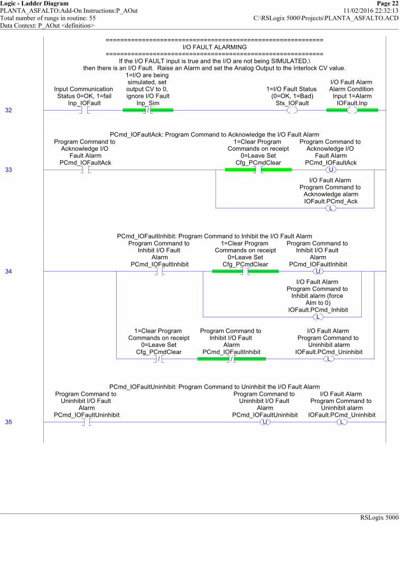
Logic - Ladder Diagram Page 22PLANTA_ASFALTO:Add-On Instructions:P_AOut 11/02/2016 22:32:13Total number of rungs in routine: 55 C:\RSLogix 5000\Projects\PLANTA_ASFALTO.ACDData Context: P_AOut <definition>
RSLogix 5000
============================================================I/O FAULT ALARMING
============================================================If the I/O FAULT input is true and the I/O are not being SIMULATED,\
then there is an I/O Fault. Raise an Alarm and set the Analog Output to the Interlock CV value.
32
Input Communication Status 0=OK, 1=fail
Inp_IOFault/
1=I/O are being simulated, set output CV to 0, ignore I/O Fault
Inp_Sim
1=I/O Fault Status (0=OK, 1=Bad)
Sts_IOFault
I/O Fault Alarm Alarm Condition
Input 1=AlarmIOFault.Inp
============================================================I/O FAULT ALARMING
============================================================If the I/O FAULT input is true and the I/O are not being SIMULATED,\
then there is an I/O Fault. Raise an Alarm and set the Analog Output to the Interlock CV value.
PCmd_IOFaultAck: Program Command to Acknowledge the I/O Fault Alarm
33
Program Command to Acknowledge I/O
Fault AlarmPCmd_IOFaultAck
1=Clear Program Commands on receipt
0=Leave SetCfg_PCmdClear
U
Program Command to Acknowledge I/O
Fault AlarmPCmd_IOFaultAck
L
I/O Fault Alarm Program Command to
Acknowledge alarmIOFault.PCmd_Ack
PCmd_IOFaultAck: Program Command to Acknowledge the I/O Fault Alarm
PCmd_IOFaultInhibit: Program Command to Inhibit the I/O Fault Alarm
34
Program Command to Inhibit I/O Fault
AlarmPCmd_IOFaultInhibit
1=Clear Program Commands on receipt
0=Leave SetCfg_PCmdClear
U
Program Command to Inhibit I/O Fault
AlarmPCmd_IOFaultInhibit
L
I/O Fault Alarm Program Command to
Inhibit alarm (force Alm to 0)
IOFault.PCmd_Inhibit
/
1=Clear Program Commands on receipt
0=Leave SetCfg_PCmdClear
/
Program Command to Inhibit I/O Fault
AlarmPCmd_IOFaultInhibit
L
I/O Fault Alarm Program Command to
Uninhibit alarmIOFault.PCmd_Uninhibit
PCmd_IOFaultInhibit: Program Command to Inhibit the I/O Fault Alarm
PCmd_IOFaultUninhibit: Program Command to Uninhibit the I/O Fault Alarm
35
Program Command to Uninhibit I/O Fault
AlarmPCmd_IOFaultUninhibit
U
Program Command to Uninhibit I/O Fault
AlarmPCmd_IOFaultUninhibit
L
I/O Fault Alarm Program Command to
Uninhibit alarmIOFault.PCmd_Uninhibit
PCmd_IOFaultUninhibit: Program Command to Uninhibit the I/O Fault Alarm
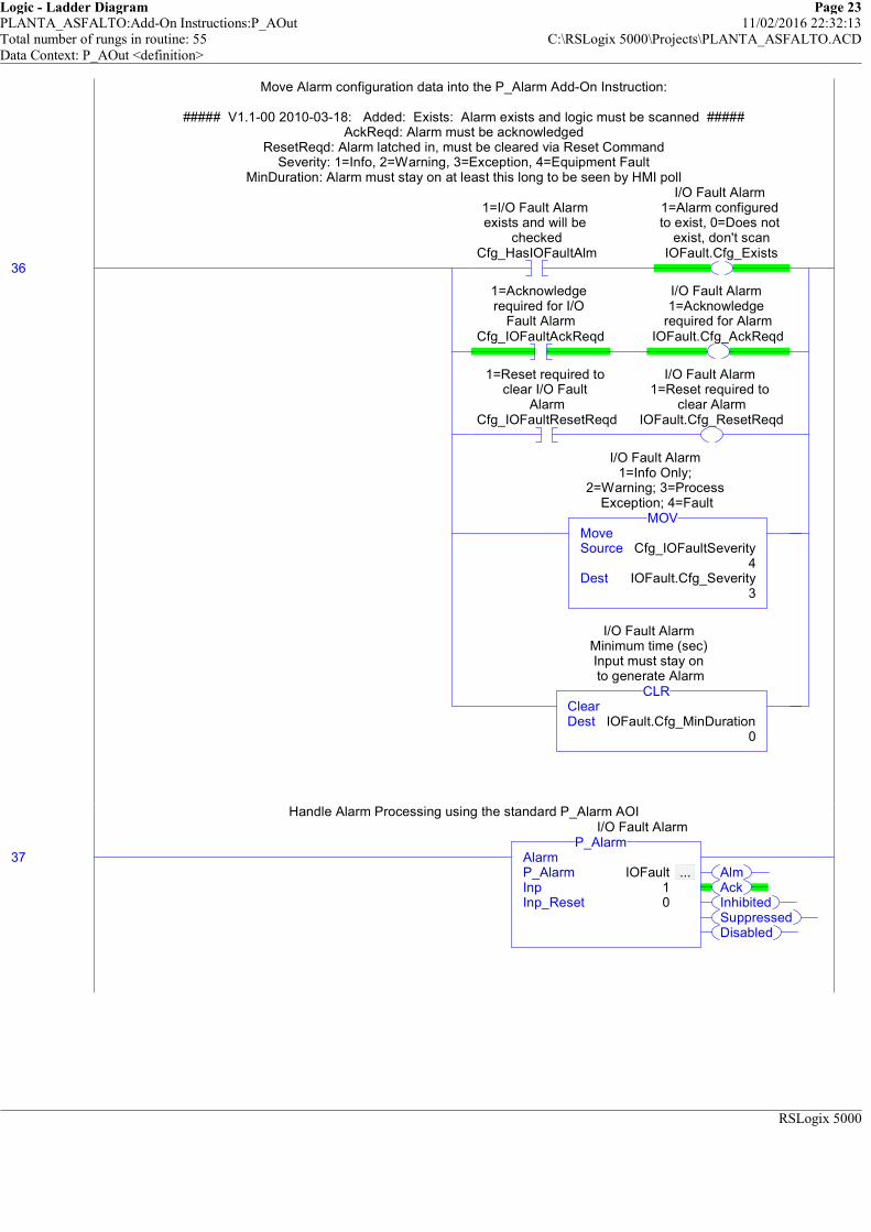
Logic - Ladder Diagram Page 23PLANTA_ASFALTO:Add-On Instructions:P_AOut 11/02/2016 22:32:13Total number of rungs in routine: 55 C:\RSLogix 5000\Projects\PLANTA_ASFALTO.ACDData Context: P_AOut <definition>
RSLogix 5000
Move Alarm configuration data into the P_Alarm Add-On Instruction:
##### V1.1-00 2010-03-18: Added: Exists: Alarm exists and logic must be scanned #####AckReqd: Alarm must be acknowledged
ResetReqd: Alarm latched in, must be cleared via Reset CommandSeverity: 1=Info, 2=Warning, 3=Exception, 4=Equipment Fault
MinDuration: Alarm must stay on at least this long to be seen by HMI poll
Handle Alarm Processing using the standard P_Alarm AOI
36
1=I/O Fault Alarm exists and will be
checkedCfg_HasIOFaultAlm
I/O Fault Alarm 1=Alarm configured to exist, 0=Does not
exist, don't scanIOFault.Cfg_Exists
1=Acknowledge required for I/O
Fault AlarmCfg_IOFaultAckReqd
I/O Fault Alarm 1=Acknowledge
required for AlarmIOFault.Cfg_AckReqd
1=Reset required to clear I/O Fault
AlarmCfg_IOFaultResetReqd
I/O Fault Alarm 1=Reset required to
clear AlarmIOFault.Cfg_ResetReqd
MoveSource Cfg_IOFaultSeverity
4Dest IOFault.Cfg_Severity
3
MOV
I/O Fault Alarm 1=Info Only;
2=Warning; 3=Process Exception; 4=Fault
ClearDest IOFault.Cfg_MinDuration
0
CLR
I/O Fault Alarm Minimum time (sec) Input must stay on to generate Alarm
Move Alarm configuration data into the P_Alarm Add-On Instruction:
##### V1.1-00 2010-03-18: Added: Exists: Alarm exists and logic must be scanned #####AckReqd: Alarm must be acknowledged
ResetReqd: Alarm latched in, must be cleared via Reset CommandSeverity: 1=Info, 2=Warning, 3=Exception, 4=Equipment Fault
MinDuration: Alarm must stay on at least this long to be seen by HMI poll
37AlmAckInhibitedSuppressedDisabled
AlarmP_Alarm IOFault ... Inp 1Inp_Reset 0
P_AlarmI/O Fault Alarm
Handle Alarm Processing using the standard P_Alarm AOI
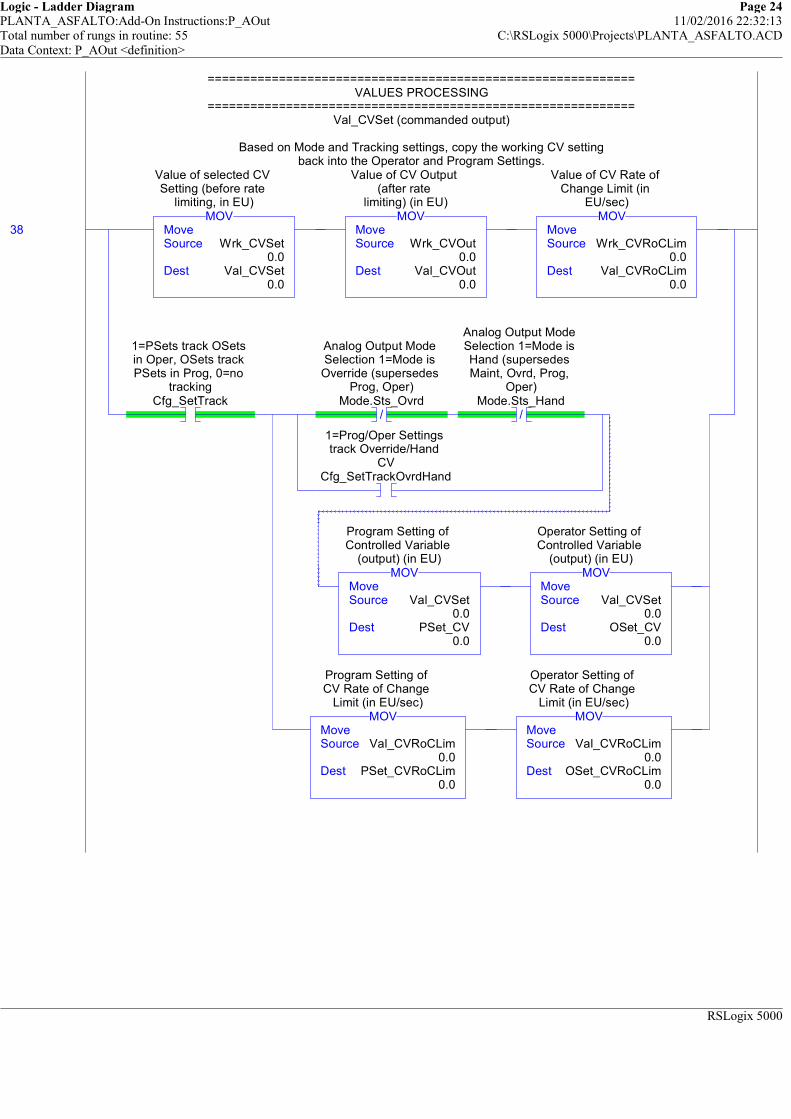
Logic - Ladder Diagram Page 24PLANTA_ASFALTO:Add-On Instructions:P_AOut 11/02/2016 22:32:13Total number of rungs in routine: 55 C:\RSLogix 5000\Projects\PLANTA_ASFALTO.ACDData Context: P_AOut <definition>
RSLogix 5000
============================================================VALUES PROCESSING
============================================================Val_CVSet (commanded output)
Based on Mode and Tracking settings, copy the working CV settingback into the Operator and Program Settings.
38 MoveSource Wrk_CVSet
0.0Dest Val_CVSet
0.0
MOV
Value of selected CV Setting (before rate
limiting, in EU)
MoveSource Wrk_CVOut
0.0Dest Val_CVOut
0.0
MOV
Value of CV Output (after rate
limiting) (in EU)
MoveSource Wrk_CVRoCLim
0.0Dest Val_CVRoCLim
0.0
MOV
Value of CV Rate of Change Limit (in
EU/sec)
1=PSets track OSets in Oper, OSets track PSets in Prog, 0=no
trackingCfg_SetTrack
/
Analog Output Mode Selection 1=Mode is Override (supersedes
Prog, Oper)Mode.Sts_Ovrd
/
Analog Output Mode Selection 1=Mode is Hand (supersedes Maint, Ovrd, Prog,
Oper)Mode.Sts_Hand
1=Prog/Oper Settings track Override/Hand
CVCfg_SetTrackOvrdHand
MoveSource Val_CVSet
0.0Dest PSet_CV
0.0
MOV
Program Setting of Controlled Variable
(output) (in EU)
MoveSource Val_CVSet
0.0Dest OSet_CV
0.0
MOV
Operator Setting of Controlled Variable
(output) (in EU)
MoveSource Val_CVRoCLim
0.0Dest PSet_CVRoCLim
0.0
MOV
Program Setting of CV Rate of Change
Limit (in EU/sec)
MoveSource Val_CVRoCLim
0.0Dest OSet_CVRoCLim
0.0
MOV
Operator Setting of CV Rate of Change
Limit (in EU/sec)
============================================================VALUES PROCESSING
============================================================Val_CVSet (commanded output)
Based on Mode and Tracking settings, copy the working CV settingback into the Operator and Program Settings.

Logic - Ladder Diagram Page 25PLANTA_ASFALTO:Add-On Instructions:P_AOut 11/02/2016 22:32:13Total number of rungs in routine: 55 C:\RSLogix 5000\Projects\PLANTA_ASFALTO.ACDData Context: P_AOut <definition>
RSLogix 5000
This rung publishes the Values for the scaled range.If this instruction is reverse scaled by reversing the scaled (EU) min and max configurations,the values are swapped so the the EUMax Value is always greater than the EUMin Value.
This makes the HMI bargraph and trend coding easier, and provides valuesthat can be pinned to the CV EU configuration of a PID, so the AOut and PID ranges are in lockstep.
39 Grtr Than or Eql (A>=B)Source A Cfg_CVEUMax
100.0Source B Cfg_CVEUMin
0.0
GEQ
CV Maximum in Engineering Units
(for scaling)
MoveSource Cfg_CVEUMin
0.0Dest Val_CVEUMin
0.0
MOV
Minimum of scaled range = MIN
(Cfg_CVEUMin, Cfg_CVEUMax)
MoveSource Cfg_CVEUMax
100.0Dest Val_CVEUMax
100.0
MOV
Maximum of scaled range = MAX
(Cfg_CVEUMin, Cfg_CVEUMax)
Less Than (A<B)Source A Cfg_CVEUMax
100.0Source B Cfg_CVEUMin
0.0
LES
CV Maximum in Engineering Units
(for scaling)
MoveSource Cfg_CVEUMin
0.0Dest Val_CVEUMax
100.0
MOV
Maximum of scaled range = MAX
(Cfg_CVEUMin, Cfg_CVEUMax)
MoveSource Cfg_CVEUMax
100.0Dest Val_CVEUMin
0.0
MOV
Minimum of scaled range = MIN
(Cfg_CVEUMin, Cfg_CVEUMax)
This rung publishes the Values for the scaled range.If this instruction is reverse scaled by reversing the scaled (EU) min and max configurations,the values are swapped so the the EUMax Value is always greater than the EUMin Value.
This makes the HMI bargraph and trend coding easier, and provides valuesthat can be pinned to the CV EU configuration of a PID, so the AOut and PID ranges are in lockstep.

Logic - Ladder Diagram Page 26PLANTA_ASFALTO:Add-On Instructions:P_AOut 11/02/2016 22:32:14Total number of rungs in routine: 55 C:\RSLogix 5000\Projects\PLANTA_ASFALTO.ACDData Context: P_AOut <definition>
RSLogix 5000
============================================================STATUS GENERATION
============================================================The following rungs generate Status bits for this object.
These Status bits are a copy of the internal Mode AOI bits forHand, Maint, Ovrd, Prog, Oper, and mode Locked.
NOTE for Sts_Disabled: This Analog Output is DISABLEDif this instruction is on a False Rung (Enable In False). See the Enable In False Routine.
40
Analog Output Mode Selection 1=Mode is Hand (supersedes Maint, Ovrd, Prog,
Oper)Mode.Sts_Hand
1=Mode is Hand (supersedes Maint, Ovrd, Prog, Oper)
Sts_Hand
Analog Output Mode Selection 1=Mode is
Maintenance (supersedes Ovrd,
Prog, Oper)Mode.Sts_Maint
1=Mode is Maintenance
(supersedes Ovrd, Prog, Oper)Sts_Maint
Analog Output Mode Selection 1=Mode is
Override (supersedes Prog, Oper)
Mode.Sts_Ovrd
1=Mode is Override (supersedes Prog,
Oper)Sts_Ovrd
Analog Output Mode Selection 1=Mode is
ProgramMode.Sts_Prog
1=Mode is Program (auto)
Sts_Prog
Analog Output Mode Selection 1=Mode is
OperatorMode.Sts_Oper
1=Mode is Operator (manual)Sts_Oper
Analog Output Mode Selection 1=Program
or Operator has requested Mode Lock
Mode.Sts_ProgOperLock
1=Program or Operator has
requested Mode LockSts_ProgOperLock
============================================================STATUS GENERATION
============================================================The following rungs generate Status bits for this object.
These Status bits are a copy of the internal Mode AOI bits forHand, Maint, Ovrd, Prog, Oper, and mode Locked.
NOTE for Sts_Disabled: This Analog Output is DISABLEDif this instruction is on a False Rung (Enable In False). See the Enable In False Routine.
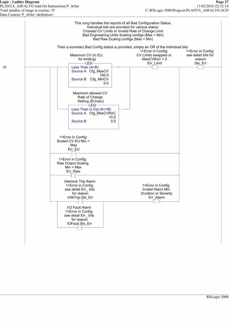
Logic - Ladder Diagram Page 27PLANTA_ASFALTO:Add-On Instructions:P_AOut 11/02/2016 22:32:14Total number of rungs in routine: 55 C:\RSLogix 5000\Projects\PLANTA_ASFALTO.ACDData Context: P_AOut <definition>
RSLogix 5000
This rung handles the reports of all Bad Configuration Status.Individual bits are provided for various status:
Crossed CV Limits or Invalid Rate of Change LimitBad Engineering Units Scaling configs (Max = Min)
Bad Raw Scaling configs (Max = Min)
Then a summary Bad Config status is provided, simply an OR of the individual bits.
41 Less Than (A<B)Source A Cfg_MaxCV
100.0Source B Cfg_MinCV
0.0
LES
Maximum CV (in EU, for limiting)
Less Than or Eql (A<=B)Source A Cfg_MaxCVRoC
10.0Source B 0.0
LEQ
Maximum allowed CV Rate of Change Setting (EU/sec)
1=Error in Config: CV Limits swapped or
MaxCVRoC < 0Err_Limit
1=Error in Config: Scaled CV EU Min =
MaxErr_EU
1=Error in Config: Raw Output Scaling
Min = MaxErr_Raw
Interlock Trip Alarm 1=Error in Config: see detail Err_ bits
for reasonIntlkTrip.Sts_Err
I/O Fault Alarm 1=Error in Config: see detail Err_ bits
for reasonIOFault.Sts_Err
1=Error in Config: Invalid Alarm Min
Duration or SeverityErr_Alarm
1=Error in Config: see detail bits for
reasonSts_Err
This rung handles the reports of all Bad Configuration Status.Individual bits are provided for various status:
Crossed CV Limits or Invalid Rate of Change LimitBad Engineering Units Scaling configs (Max = Min)
Bad Raw Scaling configs (Max = Min)
Then a summary Bad Config status is provided, simply an OR of the individual bits.

Logic - Ladder Diagram Page 28PLANTA_ASFALTO:Add-On Instructions:P_AOut 11/02/2016 22:32:14Total number of rungs in routine: 55 C:\RSLogix 5000\Projects\PLANTA_ASFALTO.ACDData Context: P_AOut <definition>
RSLogix 5000
Alarm Status bits are a copy of the internal Alarm AOI Status bits.
42
Interlock Trip Alarm Alarm output 1=In
AlarmIntlkTrip.Alm
1=Alarm: CV held or forced by interlock
NOT OKAlm_IntlkTrip
Interlock Trip Alarm Alarm acknowledged
status: 1=Ack rcvdIntlkTrip.Ack
1=Interlock Trip Alarm has been acknowledgedAck_IntlkTrip
Interlock Trip Alarm 1=Alarm has been
Disabled by Maintanance (will
not be sent)IntlkTrip.Disabled
1=Interlock Trip Alarm is Disabled (not saved or sent)
Sts_IntlkTripDisabled
Interlock Trip Alarm 1=Alarm has been
Inhibited by Program (will not be sent)IntlkTrip.Inhibited
1=Interlock Trip Alarm has been inhibited by logic
Sts_IntlkTripInhibited
Interlock Trip Alarm 1=Alarm has been
Suppressed by Operator (not visible on HMI)
IntlkTrip.Suppressed
1=Interlock Trip Alarm has been
suppressed (logged only)
Sts_IntlkTripSuppressed
Alarm Status bits are a copy of the internal Alarm AOI Status bits.
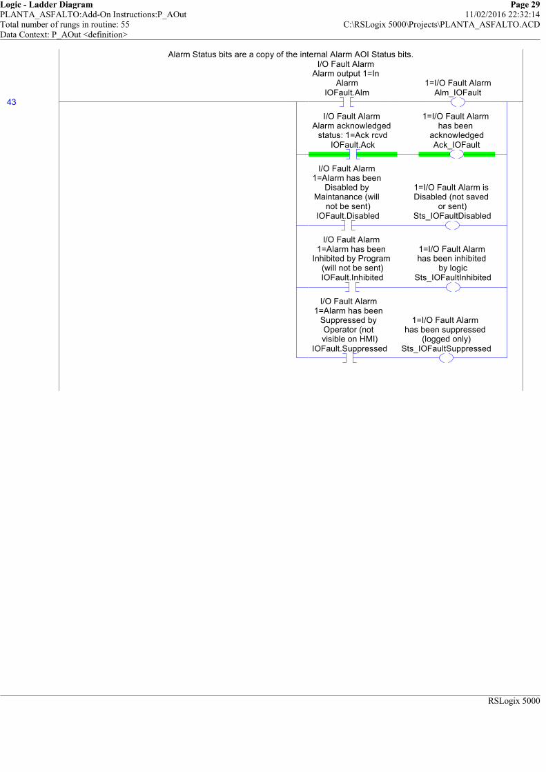
Logic - Ladder Diagram Page 29PLANTA_ASFALTO:Add-On Instructions:P_AOut 11/02/2016 22:32:14Total number of rungs in routine: 55 C:\RSLogix 5000\Projects\PLANTA_ASFALTO.ACDData Context: P_AOut <definition>
RSLogix 5000
Alarm Status bits are a copy of the internal Alarm AOI Status bits.
43
I/O Fault Alarm Alarm output 1=In
AlarmIOFault.Alm
1=I/O Fault AlarmAlm_IOFault
I/O Fault Alarm Alarm acknowledged
status: 1=Ack rcvdIOFault.Ack
1=I/O Fault Alarm has been
acknowledgedAck_IOFault
I/O Fault Alarm 1=Alarm has been
Disabled by Maintanance (will
not be sent)IOFault.Disabled
1=I/O Fault Alarm is Disabled (not saved
or sent)Sts_IOFaultDisabled
I/O Fault Alarm 1=Alarm has been
Inhibited by Program (will not be sent)IOFault.Inhibited
1=I/O Fault Alarm has been inhibited
by logicSts_IOFaultInhibited
I/O Fault Alarm 1=Alarm has been
Suppressed by Operator (not visible on HMI)
IOFault.Suppressed
1=I/O Fault Alarm has been suppressed
(logged only)Sts_IOFaultSuppressed
Alarm Status bits are a copy of the internal Alarm AOI Status bits.

Logic - Ladder Diagram Page 30PLANTA_ASFALTO:Add-On Instructions:P_AOut 11/02/2016 22:32:14Total number of rungs in routine: 55 C:\RSLogix 5000\Projects\PLANTA_ASFALTO.ACDData Context: P_AOut <definition>
RSLogix 5000
============================================================NOTIFICATION VALUE
============================================================Indicate the current alarm notification level as the max of any of the alarms:
0 = none2 = info or prompt only
4 = warning6 = exception (equipment impact)
8 = fault (equipment failure)Add one for any unsuppressed alarm that is not acknowledged (for blink).
44 ClearDest Wrk_Notify
0
CLR
Buffer for building Val_Notify
Greater Than (A>B)Source A IntlkTrip.Val_Notify
0Source B Wrk_Notify
0
GRT
Interlock Trip Alarm Current Alarm Level
and Acknowledgement (enumeration)
MoveSource IntlkTrip.Val_Notify
0Dest Wrk_Notify
0
MOV
Buffer for building Val_Notify
Greater Than (A>B)Source A IOFault.Val_Notify
0Source B Wrk_Notify
0
GRT
I/O Fault Alarm Current Alarm Level
and Acknowledgement (enumeration)
MoveSource IOFault.Val_Notify
0Dest Wrk_Notify
0
MOV
Buffer for building Val_Notify
Interlock Trip Alarm Current Alarm Level
and Acknowledgement (enumeration)
IntlkTrip.Val_Notify.0
I/O Fault Alarm Current Alarm Level
and Acknowledgement (enumeration)
IOFault.Val_Notify.0
Buffer for building Val_Notify
Wrk_Notify.0
MoveSource Wrk_Notify
0Dest Val_Notify
0
MOV
Current Alarm Level and Acknowledgement
(enumeration)
============================================================NOTIFICATION VALUE
============================================================Indicate the current alarm notification level as the max of any of the alarms:
0 = none2 = info or prompt only
4 = warning6 = exception (equipment impact)
8 = fault (equipment failure)Add one for any unsuppressed alarm that is not acknowledged (for blink).

Logic - Ladder Diagram Page 31PLANTA_ASFALTO:Add-On Instructions:P_AOut 11/02/2016 22:32:14Total number of rungs in routine: 55 C:\RSLogix 5000\Projects\PLANTA_ASFALTO.ACDData Context: P_AOut <definition>
RSLogix 5000
The Analog Output is AVAILABLE to be controlled by automation if it isin Program Mode, not Disabled, interlocks are OK, and I/O Communication is OK.
45
Analog Output Mode Selection 1=Mode is
ProgramMode.Sts_Prog
/
Internal Analog Output is Disabled
Wrk_Disabled
1=Interlocks OK, Analog Output can be
setInp_IntlkOK
Internal Bypassable Interlocks are Bypassed flagWrk_Bypass
1=Non-Bypassable Interlocks OK,
Analog Output can be set
Inp_NBIntlkOK
/
Input Communication Status 0=OK, 1=fail
Inp_IOFault
1=I/O are being simulated, set output CV to 0, ignore I/O Fault
Inp_Sim
1=Analog Output available for control by
automation (Prog)Sts_Available
The Analog Output is AVAILABLE to be controlled by automation if it isin Program Mode, not Disabled, interlocks are OK, and I/O Communication is OK.
##### V1.1-00 2010-03-18: Modified Rung #####
If the internal Bypass flag is set, Bypassable Interlocks ARE BYPASSED.Bypassing is ACTIVE if Bypass selected OR in Maintenance Mode,
or in Override Mode if Override Bypassing is configured.
46
Internal Bypassable Interlocks are Bypassed flagWrk_Bypass
1=Bypassable Interlocks are
BypassedSts_Bypass
Analog Output Mode Selection 1=Mode is
Maintenance (supersedes Ovrd,
Prog, Oper)Mode.Sts_Maint
Analog Output Mode Selection 1=Mode is
Override (supersedes Prog, Oper)
Mode.Sts_Ovrd
1=Override ignores Bypassable Intlk; 0=always use Intlk
Cfg_OvrdIntlk
1=Bypassing Active (Bypassed or Maintenance)Sts_BypActive
##### V1.1-00 2010-03-18: Modified Rung #####
If the internal Bypass flag is set, Bypassable Interlocks ARE BYPASSED.Bypassing is ACTIVE if Bypass selected OR in Maintenance Mode,
or in Override Mode if Override Bypassing is configured.
If the internal Disabled flag is set, the Analog Output is DISABLED.
47
Internal Analog Output is Disabled
Wrk_Disabled1=Output is Disabled
Sts_Disabled
If the internal Disabled flag is set, the Analog Output is DISABLED.

Logic - Ladder Diagram Page 32PLANTA_ASFALTO:Add-On Instructions:P_AOut 11/02/2016 22:32:14Total number of rungs in routine: 55 C:\RSLogix 5000\Projects\PLANTA_ASFALTO.ACDData Context: P_AOut <definition>
RSLogix 5000
============================================================OPERATOR COMMAND READIES
============================================================
Ready to Bypass all Bypassable Interlocks if not bypassed.
48 /
Internal Bypassable Interlocks are Bypassed flagWrk_Bypass
1=Ready to receive OCmd_Bypass (enables
HMI button)Rdy_Bypass
============================================================OPERATOR COMMAND READIES
============================================================
Ready to Bypass all Bypassable Interlocks if not bypassed.
Ready to Check Bypassable Interlocks if bypassed.
49
Internal Bypassable Interlocks are Bypassed flagWrk_Bypass
1=Ready to receive OCmd_Check (enables
HMI button)Rdy_Check
Ready to Check Bypassable Interlocks if bypassed.
Ready to Disable Analog Output if not Disabled
50 /
Internal Analog Output is Disabled
Wrk_Disabled
1=Ready to receive MCmd_Disable
(enables HMI button)Rdy_Disable
Ready to Disable Analog Output if not Disabled
Ready to Enable Analog Output if Disabled.
51
Internal Analog Output is Disabled
Wrk_Disabled
1=Ready to receive MCmd_Enable (enables
HMI button)Rdy_Enable
Ready to Enable Analog Output if Disabled.
This object requires a Reset if any of its Alarms requires a Reset.
52
Interlock Trip Alarm Ready to receive
OCmd_Reset (enable button)
IntlkTrip.Rdy_Reset
I/O Fault Alarm Ready to receive
OCmd_Reset (enable button)
IOFault.Rdy_Reset
1=Ready to receive OCmd_Reset (enables
HMI button)Rdy_Reset
This object requires a Reset if any of its Alarms requires a Reset.

Logic - Ladder Diagram Page 33PLANTA_ASFALTO:Add-On Instructions:P_AOut 11/02/2016 22:32:14Total number of rungs in routine: 55 C:\RSLogix 5000\Projects\PLANTA_ASFALTO.ACDData Context: P_AOut <definition>
RSLogix 5000
##### V1.1-00 2010-03-18: Added Rung #####
Ready to receive a new OSet_CV if tracking is NOT enabled,or we're in Operator or Maintenance Mode, or,
if we're in Hand or Ovrd, tracking is NOT configured for Ovrd and Hand.
53 /
1=PSets track OSets in Oper, OSets track PSets in Prog, 0=no
trackingCfg_SetTrack
Analog Output Mode Selection 1=Mode is
OperatorMode.Sts_Oper
Analog Output Mode Selection 1=Mode is
Maintenance (supersedes Ovrd,
Prog, Oper)Mode.Sts_Maint
Analog Output Mode Selection 1=Mode is Hand (supersedes Maint, Ovrd, Prog,
Oper)Mode.Sts_Hand
Analog Output Mode Selection 1=Mode is
Override (supersedes Prog, Oper)
Mode.Sts_Ovrd
/
1=Prog/Oper Settings track Override/Hand
CVCfg_SetTrackOvrdHand
1=Ready to receive OSet_CV (enables
data entry field)Rdy_CV
##### V1.1-00 2010-03-18: Added Rung #####
Ready to receive a new OSet_CV if tracking is NOT enabled,or we're in Operator or Maintenance Mode, or,
if we're in Hand or Ovrd, tracking is NOT configured for Ovrd and Hand.
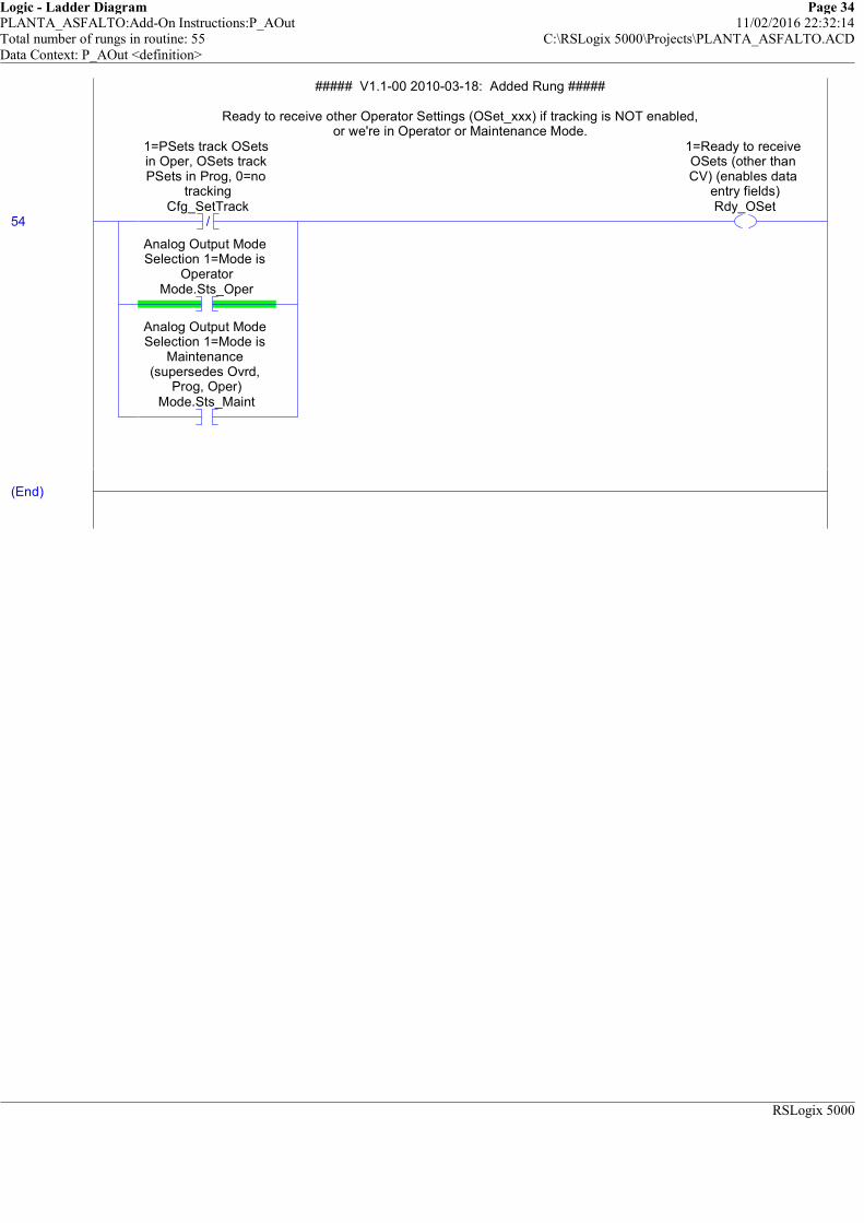
Logic - Ladder Diagram Page 34PLANTA_ASFALTO:Add-On Instructions:P_AOut 11/02/2016 22:32:14Total number of rungs in routine: 55 C:\RSLogix 5000\Projects\PLANTA_ASFALTO.ACDData Context: P_AOut <definition>
RSLogix 5000
##### V1.1-00 2010-03-18: Added Rung #####
Ready to receive other Operator Settings (OSet_xxx) if tracking is NOT enabled,or we're in Operator or Maintenance Mode.
54 /
1=PSets track OSets in Oper, OSets track PSets in Prog, 0=no
trackingCfg_SetTrack
Analog Output Mode Selection 1=Mode is
OperatorMode.Sts_Oper
Analog Output Mode Selection 1=Mode is
Maintenance (supersedes Ovrd,
Prog, Oper)Mode.Sts_Maint
1=Ready to receive OSets (other than CV) (enables data
entry fields)Rdy_OSet
##### V1.1-00 2010-03-18: Added Rung #####
Ready to receive other Operator Settings (OSet_xxx) if tracking is NOT enabled,or we're in Operator or Maintenance Mode.
(End)
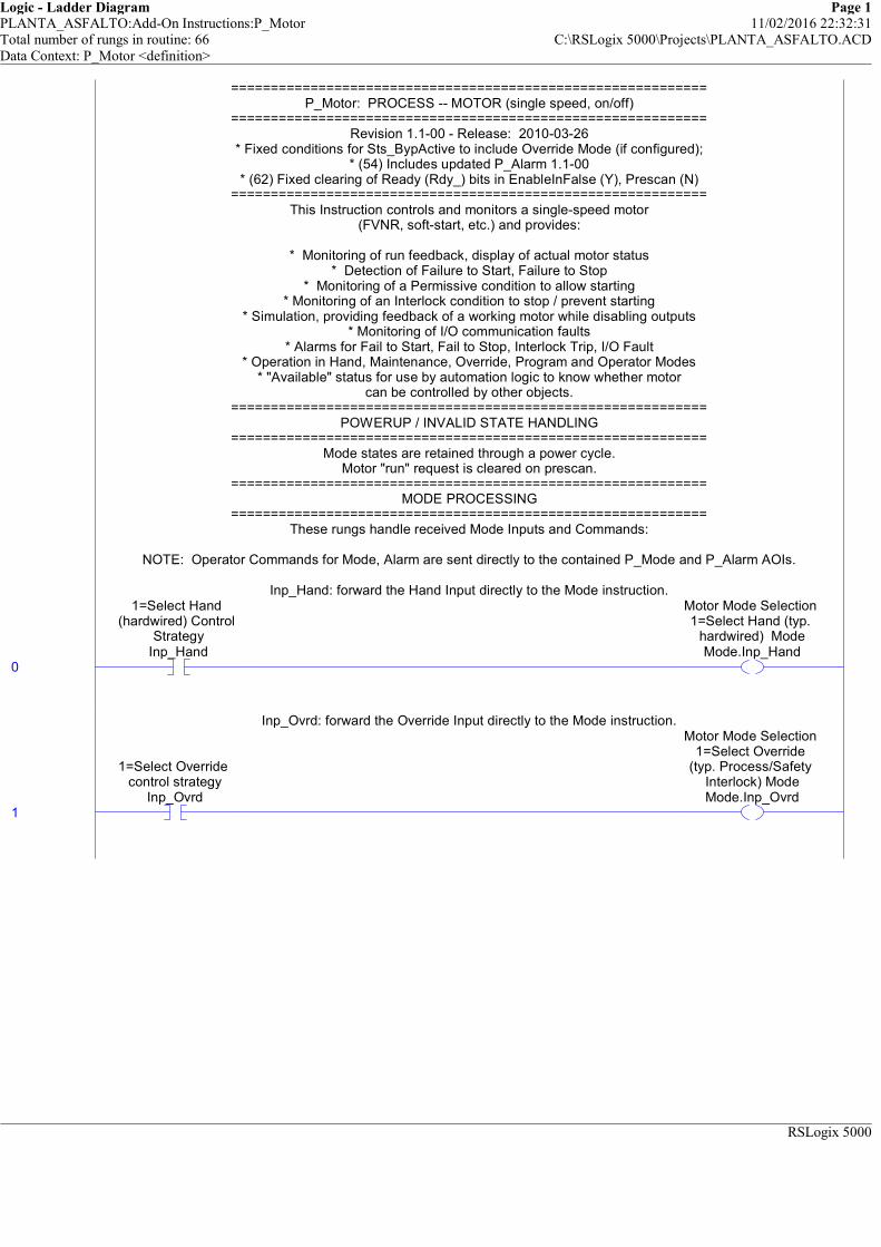
Logic - Ladder Diagram Page 1PLANTA_ASFALTO:Add-On Instructions:P_Motor 11/02/2016 22:32:31Total number of rungs in routine: 66 C:\RSLogix 5000\Projects\PLANTA_ASFALTO.ACDData Context: P_Motor <definition>
RSLogix 5000
============================================================P_Motor: PROCESS -- MOTOR (single speed, on/off)
============================================================Revision 1.1-00 - Release: 2010-03-26
* Fixed conditions for Sts_BypActive to include Override Mode (if configured);* (54) Includes updated P_Alarm 1.1-00
* (62) Fixed clearing of Ready (Rdy_) bits in EnableInFalse (Y), Prescan (N)============================================================
This Instruction controls and monitors a single-speed motor(FVNR, soft-start, etc.) and provides:
* Monitoring of run feedback, display of actual motor status* Detection of Failure to Start, Failure to Stop
* Monitoring of a Permissive condition to allow starting* Monitoring of an Interlock condition to stop / prevent starting
* Simulation, providing feedback of a working motor while disabling outputs* Monitoring of I/O communication faults
* Alarms for Fail to Start, Fail to Stop, Interlock Trip, I/O Fault* Operation in Hand, Maintenance, Override, Program and Operator Modes
* "Available" status for use by automation logic to know whether motorcan be controlled by other objects.
============================================================POWERUP / INVALID STATE HANDLING
============================================================Mode states are retained through a power cycle.
Motor "run" request is cleared on prescan.============================================================
MODE PROCESSING============================================================
These rungs handle received Mode Inputs and Commands:
NOTE: Operator Commands for Mode, Alarm are sent directly to the contained P_Mode and P_Alarm AOIs.
Inp_Hand: forward the Hand Input directly to the Mode instruction.
0
1=Select Hand (hardwired) Control
StrategyInp_Hand
Motor Mode Selection 1=Select Hand (typ.
hardwired) ModeMode.Inp_Hand
============================================================P_Motor: PROCESS -- MOTOR (single speed, on/off)
============================================================Revision 1.1-00 - Release: 2010-03-26
* Fixed conditions for Sts_BypActive to include Override Mode (if configured);* (54) Includes updated P_Alarm 1.1-00
* (62) Fixed clearing of Ready (Rdy_) bits in EnableInFalse (Y), Prescan (N)============================================================
This Instruction controls and monitors a single-speed motor(FVNR, soft-start, etc.) and provides:
* Monitoring of run feedback, display of actual motor status* Detection of Failure to Start, Failure to Stop
* Monitoring of a Permissive condition to allow starting* Monitoring of an Interlock condition to stop / prevent starting
* Simulation, providing feedback of a working motor while disabling outputs* Monitoring of I/O communication faults
* Alarms for Fail to Start, Fail to Stop, Interlock Trip, I/O Fault* Operation in Hand, Maintenance, Override, Program and Operator Modes
* "Available" status for use by automation logic to know whether motorcan be controlled by other objects.
============================================================POWERUP / INVALID STATE HANDLING
============================================================Mode states are retained through a power cycle.
Motor "run" request is cleared on prescan.============================================================
MODE PROCESSING============================================================
These rungs handle received Mode Inputs and Commands:
NOTE: Operator Commands for Mode, Alarm are sent directly to the contained P_Mode and P_Alarm AOIs.
Inp_Hand: forward the Hand Input directly to the Mode instruction.
Inp_Ovrd: forward the Override Input directly to the Mode instruction.
1
1=Select Override control strategy
Inp_Ovrd
Motor Mode Selection 1=Select Override
(typ. Process/Safety Interlock) ModeMode.Inp_Ovrd
Inp_Ovrd: forward the Override Input directly to the Mode instruction.

Logic - Ladder Diagram Page 2PLANTA_ASFALTO:Add-On Instructions:P_Motor 11/02/2016 22:32:40Total number of rungs in routine: 66 C:\RSLogix 5000\Projects\PLANTA_ASFALTO.ACDData Context: P_Motor <definition>
RSLogix 5000
PCmd_Acq: Program Command to Acquire ownership
2
Program Command to Acquire ownership
(Oper to Prog)PCmd_Acq
1=Clear Program Commands on receipt
0=Leave SetCfg_PCmdClear
U
Program Command to Acquire ownership
(Oper to Prog)PCmd_Acq
L
Motor Mode Selection Program Command to
Acquire Ownership (Oper to Prog)
Mode.PCmd_Acq
/
Program Command to Acquire ownership
(Oper to Prog)PCmd_Acq
/
1=Clear Program Commands on receipt
0=Leave SetCfg_PCmdClear
U
Motor Mode Selection Program Command to
Acquire Ownership (Oper to Prog)
Mode.PCmd_Acq
PCmd_Acq: Program Command to Acquire ownership
PCmd_Rel: Program Command to Release ownership (to Oper)
3
Program Command to Release ownership
(Prog to Oper)PCmd_Rel
U
Program Command to Release ownership
(Prog to Oper)PCmd_Rel
L
Motor Mode Selection Program Command to Release Ownership
(Prog to Oper)Mode.PCmd_Rel
PCmd_Rel: Program Command to Release ownership (to Oper)
PCmd_Lock: Program Command to Lock ownership in Prog Mode
4
Program Command to Lock Mode in Prog
PCmd_Lock
1=Clear Program Commands on receipt
0=Leave SetCfg_PCmdClear
U
Program Command to Lock Mode in Prog
PCmd_Lock
L
Motor Mode Selection Program Command to
Lock Mode in ProgMode.PCmd_Lock
/
Program Command to Lock Mode in Prog
PCmd_Lock/
1=Clear Program Commands on receipt
0=Leave SetCfg_PCmdClear
U
Motor Mode Selection Program Command to
Lock Mode in ProgMode.PCmd_Lock
PCmd_Lock: Program Command to Lock ownership in Prog Mode
PCmd_Unlock: Program Command to Unlock Mode
5
Program Command to Unlock Mode
PCmd_UnlockU
Program Command to Unlock Mode
PCmd_UnlockL
Motor Mode Selection Program Command to
Unlock ModeMode.PCmd_Unlock
PCmd_Unlock: Program Command to Unlock Mode
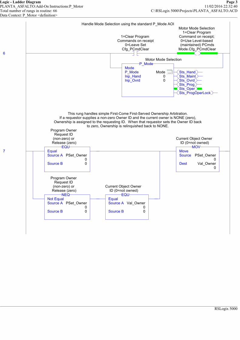
Logic - Ladder Diagram Page 3PLANTA_ASFALTO:Add-On Instructions:P_Motor 11/02/2016 22:32:40Total number of rungs in routine: 66 C:\RSLogix 5000\Projects\PLANTA_ASFALTO.ACDData Context: P_Motor <definition>
RSLogix 5000
Handle Mode Selection using the standard P_Mode AOI
6
1=Clear Program Commands on receipt
0=Leave SetCfg_PCmdClear
Motor Mode Selection 1=Clear Program
Command on receipt; 0=Use Level-based (maintained) PCmds
Mode.Cfg_PCmdClear
Sts_HandSts_MaintSts_OvrdSts_ProgSts_OperSts_ProgOperLock
ModeP_Mode Mode ... Inp_Hand 0Inp_Ovrd 0
P_ModeMotor Mode Selection
Handle Mode Selection using the standard P_Mode AOI
This rung handles simple First-Come First-Served Ownership Arbitration.If a requestor supplies a non-zero Owner ID and the current owner is NONE (zero),
Ownership is assigned to the requesting ID. When that requestor sets the Owner ID backto zero, Ownership is relinquished back to NONE.
7 EqualSource A PSet_Owner
0Source B 0
EQU
Program Owner Request ID
(non-zero) or Release (zero)
Not EqualSource A PSet_Owner
0Source B 0
NEQ
Program Owner Request ID
(non-zero) or Release (zero)
EqualSource A Val_Owner
0Source B 0
EQU
Current Object Owner ID (0=not owned)
MoveSource PSet_Owner
0Dest Val_Owner
0
MOV
Current Object Owner ID (0=not owned)
This rung handles simple First-Come First-Served Ownership Arbitration.If a requestor supplies a non-zero Owner ID and the current owner is NONE (zero),
Ownership is assigned to the requesting ID. When that requestor sets the Owner ID backto zero, Ownership is relinquished back to NONE.
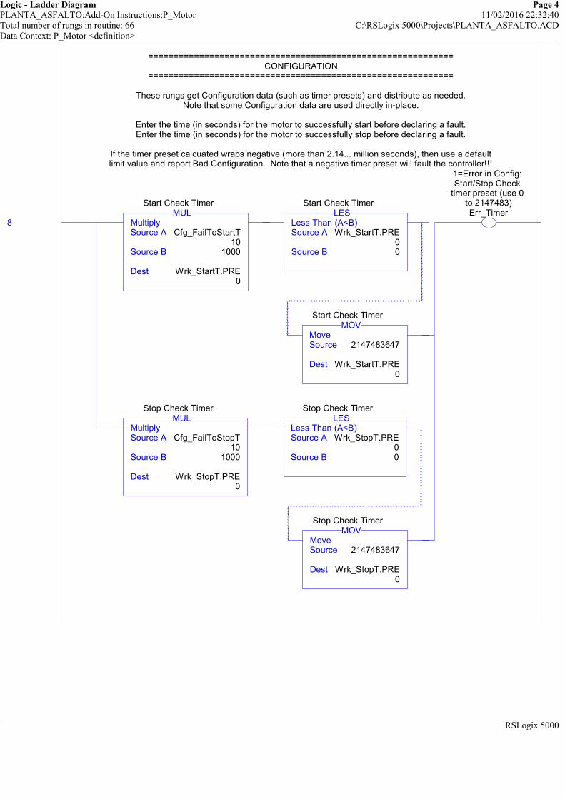
Logic - Ladder Diagram Page 4PLANTA_ASFALTO:Add-On Instructions:P_Motor 11/02/2016 22:32:40Total number of rungs in routine: 66 C:\RSLogix 5000\Projects\PLANTA_ASFALTO.ACDData Context: P_Motor <definition>
RSLogix 5000
============================================================CONFIGURATION
============================================================
These rungs get Configuration data (such as timer presets) and distribute as needed.Note that some Configuration data are used directly in-place.
Enter the time (in seconds) for the motor to successfully start before declaring a fault.Enter the time (in seconds) for the motor to successfully stop before declaring a fault.
If the timer preset calcuated wraps negative (more than 2.14... million seconds), then use a defaultlimit value and report Bad Configuration. Note that a negative timer preset will fault the controller!!!
8 MultiplySource A Cfg_FailToStartT
10Source B 1000
Dest Wrk_StartT.PRE0
MULStart Check Timer
Less Than (A<B)Source A Wrk_StartT.PRE
0Source B 0
LESStart Check Timer
MoveSource 2147483647
Dest Wrk_StartT.PRE0
MOVStart Check Timer
MultiplySource A Cfg_FailToStopT
10Source B 1000
Dest Wrk_StopT.PRE0
MULStop Check Timer
Less Than (A<B)Source A Wrk_StopT.PRE
0Source B 0
LESStop Check Timer
MoveSource 2147483647
Dest Wrk_StopT.PRE0
MOVStop Check Timer
1=Error in Config: Start/Stop Check
timer preset (use 0 to 2147483)Err_Timer
============================================================CONFIGURATION
============================================================
These rungs get Configuration data (such as timer presets) and distribute as needed.Note that some Configuration data are used directly in-place.
Enter the time (in seconds) for the motor to successfully start before declaring a fault.Enter the time (in seconds) for the motor to successfully stop before declaring a fault.
If the timer preset calcuated wraps negative (more than 2.14... million seconds), then use a defaultlimit value and report Bad Configuration. Note that a negative timer preset will fault the controller!!!
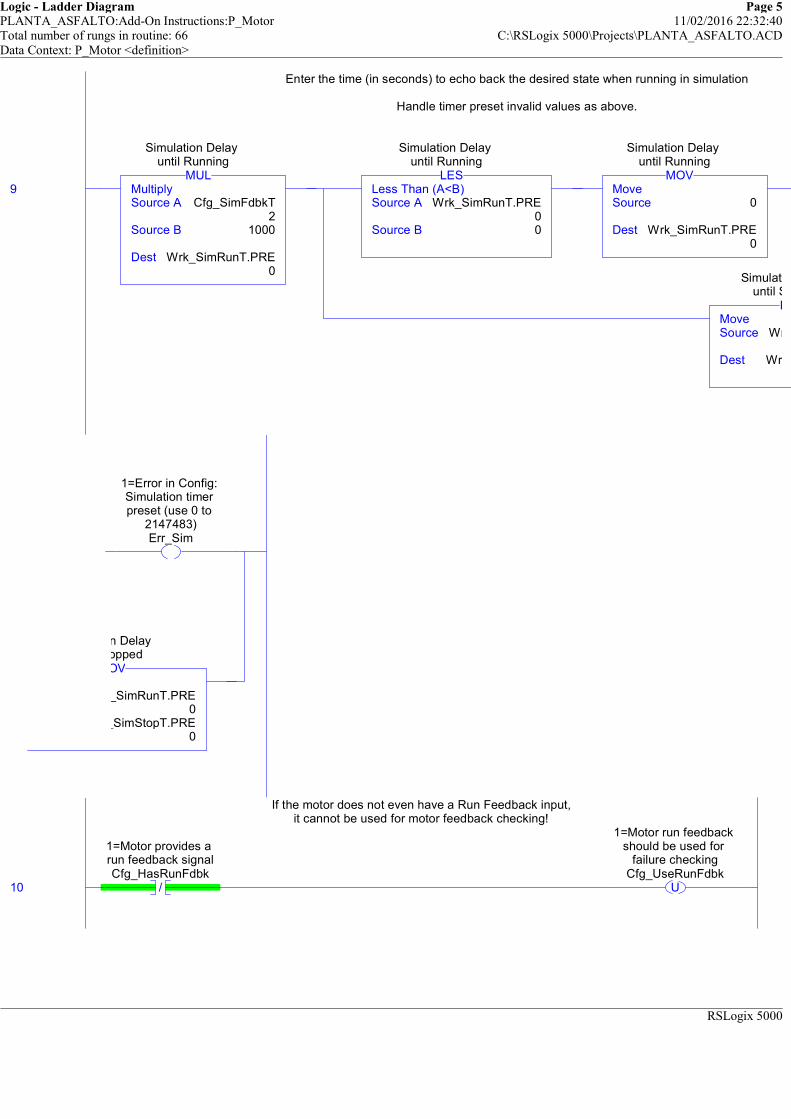
Logic - Ladder Diagram Page 5PLANTA_ASFALTO:Add-On Instructions:P_Motor 11/02/2016 22:32:40Total number of rungs in routine: 66 C:\RSLogix 5000\Projects\PLANTA_ASFALTO.ACDData Context: P_Motor <definition>
RSLogix 5000
Enter the time (in seconds) to echo back the desired state when running in simulation
Handle timer preset invalid values as above.
9 MultiplySource A Cfg_SimFdbkT
2Source B 1000
Dest Wrk_SimRunT.PRE0
MUL
Simulation Delay until Running
Less Than (A<B)Source A Wrk_SimRunT.PRE
0Source B 0
LES
Simulation Delay until Running
MoveSource 0
Dest Wrk_SimRunT.PRE0
MOV
Simulation Delay until Running
MoveSource Wrk_SimRunT.PRE
Dest Wrk_SimStopT.PRE
MOV
Simulation Delay until Stopped
Enter the time (in seconds) to echo back the desired state when running in simulation
Handle timer preset invalid values as above.
1=Error in Config: Simulation timer preset (use 0 to
2147483)Err_Sim
Wrk_SimRunT.PRE0
Wrk_SimStopT.PRE0
MOV
Simulation Delay until Stopped
If the motor does not even have a Run Feedback input,it cannot be used for motor feedback checking!
10 /
1=Motor provides a run feedback signalCfg_HasRunFdbk
U
1=Motor run feedback should be used for
failure checkingCfg_UseRunFdbk
If the motor does not even have a Run Feedback input,it cannot be used for motor feedback checking!
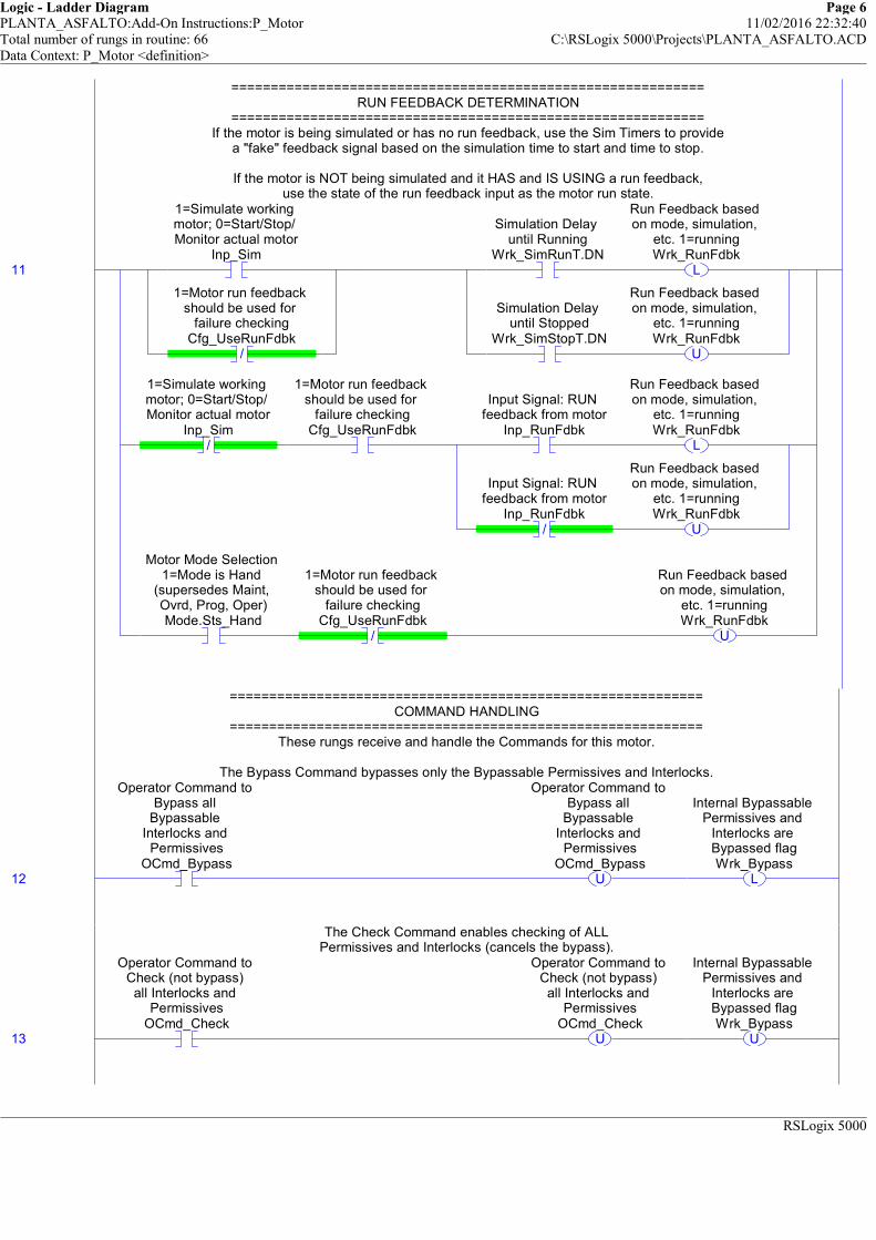
Logic - Ladder Diagram Page 6PLANTA_ASFALTO:Add-On Instructions:P_Motor 11/02/2016 22:32:40Total number of rungs in routine: 66 C:\RSLogix 5000\Projects\PLANTA_ASFALTO.ACDData Context: P_Motor <definition>
RSLogix 5000
============================================================RUN FEEDBACK DETERMINATION
============================================================If the motor is being simulated or has no run feedback, use the Sim Timers to provide
a "fake" feedback signal based on the simulation time to start and time to stop.
If the motor is NOT being simulated and it HAS and IS USING a run feedback,use the state of the run feedback input as the motor run state.
11
1=Simulate working motor; 0=Start/Stop/ Monitor actual motor
Inp_Sim
/
1=Motor run feedback should be used for
failure checkingCfg_UseRunFdbk
Simulation Delay until Running
Wrk_SimRunT.DNL
Run Feedback based on mode, simulation,
etc. 1=runningWrk_RunFdbk
Simulation Delay until Stopped
Wrk_SimStopT.DNU
Run Feedback based on mode, simulation,
etc. 1=runningWrk_RunFdbk
/
1=Simulate working motor; 0=Start/Stop/ Monitor actual motor
Inp_Sim
1=Motor run feedback should be used for
failure checkingCfg_UseRunFdbk
Input Signal: RUN feedback from motor
Inp_RunFdbkL
Run Feedback based on mode, simulation,
etc. 1=runningWrk_RunFdbk
/
Input Signal: RUN feedback from motor
Inp_RunFdbkU
Run Feedback based on mode, simulation,
etc. 1=runningWrk_RunFdbk
Motor Mode Selection 1=Mode is Hand
(supersedes Maint, Ovrd, Prog, Oper)Mode.Sts_Hand
/
1=Motor run feedback should be used for
failure checkingCfg_UseRunFdbk
U
Run Feedback based on mode, simulation,
etc. 1=runningWrk_RunFdbk
============================================================RUN FEEDBACK DETERMINATION
============================================================If the motor is being simulated or has no run feedback, use the Sim Timers to provide
a "fake" feedback signal based on the simulation time to start and time to stop.
If the motor is NOT being simulated and it HAS and IS USING a run feedback,use the state of the run feedback input as the motor run state.
============================================================COMMAND HANDLING
============================================================These rungs receive and handle the Commands for this motor.
The Bypass Command bypasses only the Bypassable Permissives and Interlocks.
12
Operator Command to Bypass all
Bypassable Interlocks and
PermissivesOCmd_Bypass
U
Operator Command to Bypass all
Bypassable Interlocks and
PermissivesOCmd_Bypass
L
Internal Bypassable Permissives and
Interlocks are Bypassed flagWrk_Bypass
============================================================COMMAND HANDLING
============================================================These rungs receive and handle the Commands for this motor.
The Bypass Command bypasses only the Bypassable Permissives and Interlocks.
The Check Command enables checking of ALLPermissives and Interlocks (cancels the bypass).
13
Operator Command to Check (not bypass) all Interlocks and
PermissivesOCmd_Check
U
Operator Command to Check (not bypass) all Interlocks and
PermissivesOCmd_Check
U
Internal Bypassable Permissives and
Interlocks are Bypassed flagWrk_Bypass
The Check Command enables checking of ALLPermissives and Interlocks (cancels the bypass).
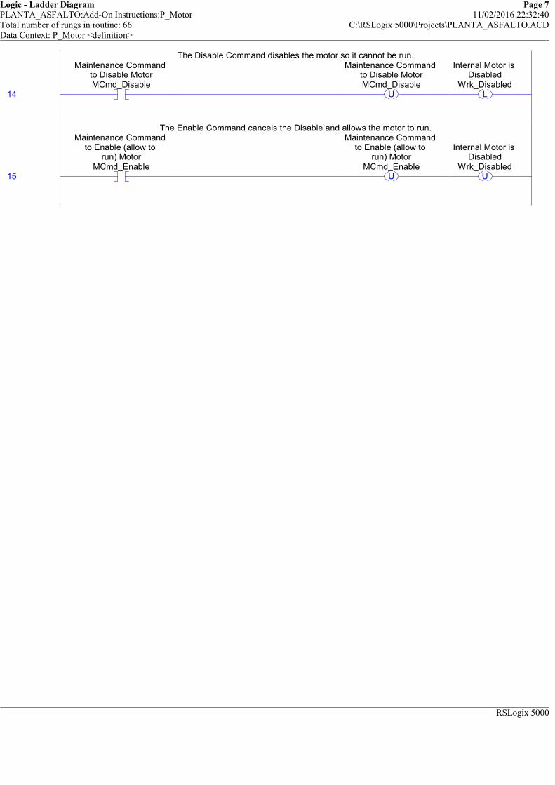
Logic - Ladder Diagram Page 7PLANTA_ASFALTO:Add-On Instructions:P_Motor 11/02/2016 22:32:40Total number of rungs in routine: 66 C:\RSLogix 5000\Projects\PLANTA_ASFALTO.ACDData Context: P_Motor <definition>
RSLogix 5000
The Disable Command disables the motor so it cannot be run.
14
Maintenance Command to Disable MotorMCmd_Disable
U
Maintenance Command to Disable MotorMCmd_Disable
L
Internal Motor is Disabled
Wrk_Disabled
The Disable Command disables the motor so it cannot be run.
The Enable Command cancels the Disable and allows the motor to run.
15
Maintenance Command to Enable (allow to
run) MotorMCmd_Enable
U
Maintenance Command to Enable (allow to
run) MotorMCmd_Enable
U
Internal Motor is Disabled
Wrk_Disabled
The Enable Command cancels the Disable and allows the motor to run.
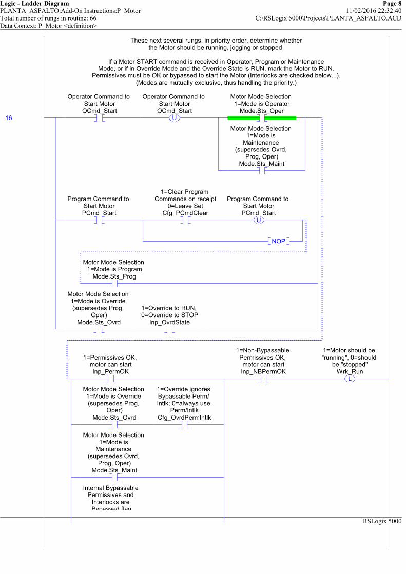
Logic - Ladder Diagram Page 8PLANTA_ASFALTO:Add-On Instructions:P_Motor 11/02/2016 22:32:40Total number of rungs in routine: 66 C:\RSLogix 5000\Projects\PLANTA_ASFALTO.ACDData Context: P_Motor <definition>
RSLogix 5000
These next several rungs, in priority order, determine whetherthe Motor should be running, jogging or stopped.
If a Motor START command is received in Operator, Program or MaintenanceMode, or if in Override Mode and the Override State is RUN, mark the Motor to RUN.
Permissives must be OK or bypassed to start the Motor (Interlocks are checked below...).(Modes are mutually exclusive, thus handling the priority.)
16
Operator Command to Start Motor
OCmd_StartU
Operator Command to Start Motor
OCmd_Start
Motor Mode Selection 1=Mode is Operator
Mode.Sts_Oper
Motor Mode Selection 1=Mode is
Maintenance (supersedes Ovrd,
Prog, Oper)Mode.Sts_Maint
Program Command to Start MotorPCmd_Start
1=Clear Program Commands on receipt
0=Leave SetCfg_PCmdClear
U
Program Command to Start MotorPCmd_Start
NOP
Motor Mode Selection 1=Mode is Program
Mode.Sts_Prog
Motor Mode Selection 1=Mode is Override (supersedes Prog,
Oper)Mode.Sts_Ovrd
1=Override to RUN, 0=Override to STOP
Inp_OvrdState
1=Permissives OK, motor can startInp_PermOK
Motor Mode Selection 1=Mode is Override (supersedes Prog,
Oper)Mode.Sts_Ovrd
1=Override ignores Bypassable Perm/ Intlk; 0=always use
Perm/IntlkCfg_OvrdPermIntlk
Motor Mode Selection 1=Mode is
Maintenance (supersedes Ovrd,
Prog, Oper)Mode.Sts_Maint
Internal Bypassable Permissives and
Interlocks are Bypassed flag
1=Non-Bypassable Permissives OK, motor can startInp_NBPermOK
L
1=Motor should be "running", 0=should
be "stopped"Wrk_Run
These next several rungs, in priority order, determine whetherthe Motor should be running, jogging or stopped.
If a Motor START command is received in Operator, Program or MaintenanceMode, or if in Override Mode and the Override State is RUN, mark the Motor to RUN.
Permissives must be OK or bypassed to start the Motor (Interlocks are checked below...).(Modes are mutually exclusive, thus handling the priority.)
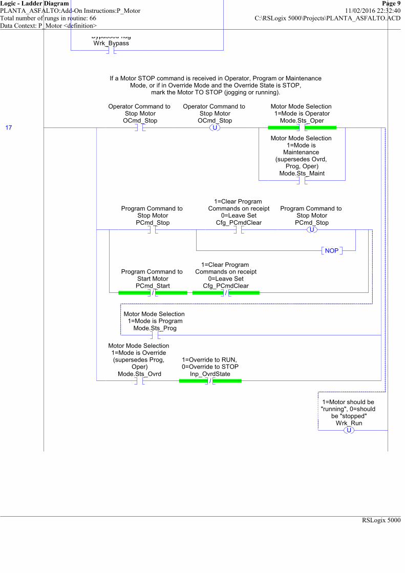
Logic - Ladder Diagram Page 9PLANTA_ASFALTO:Add-On Instructions:P_Motor 11/02/2016 22:32:40Total number of rungs in routine: 66 C:\RSLogix 5000\Projects\PLANTA_ASFALTO.ACDData Context: P_Motor <definition>
RSLogix 5000
Bypassed flagWrk_Bypass
If a Motor STOP command is received in Operator, Program or MaintenanceMode, or if in Override Mode and the Override State is STOP,
mark the Motor TO STOP (jogging or running).
17
Operator Command to Stop Motor
OCmd_StopU
Operator Command to Stop Motor
OCmd_Stop
Motor Mode Selection 1=Mode is Operator
Mode.Sts_Oper
Motor Mode Selection 1=Mode is
Maintenance (supersedes Ovrd,
Prog, Oper)Mode.Sts_Maint
Program Command to Stop MotorPCmd_Stop
1=Clear Program Commands on receipt
0=Leave SetCfg_PCmdClear
U
Program Command to Stop MotorPCmd_Stop
NOP
/
Program Command to Start MotorPCmd_Start
/
1=Clear Program Commands on receipt
0=Leave SetCfg_PCmdClear
Motor Mode Selection 1=Mode is Program
Mode.Sts_Prog
Motor Mode Selection 1=Mode is Override (supersedes Prog,
Oper)Mode.Sts_Ovrd
/
1=Override to RUN, 0=Override to STOP
Inp_OvrdState
U
1=Motor should be "running", 0=should
be "stopped"Wrk_Run
If a Motor STOP command is received in Operator, Program or MaintenanceMode, or if in Override Mode and the Override State is STOP,
mark the Motor TO STOP (jogging or running).

Logic - Ladder Diagram Page 10PLANTA_ASFALTO:Add-On Instructions:P_Motor 11/02/2016 22:32:40Total number of rungs in routine: 66 C:\RSLogix 5000\Projects\PLANTA_ASFALTO.ACDData Context: P_Motor <definition>
RSLogix 5000
Higher Priority:If Interlocks are not OK (Non-Bypassable not OK, or bypassable not OK
and not bypassed by Maintenance, Override or Bypass Command), OR if the Motor is DISABLED or FAULTED, set it to STOP.
If we tripped on an Interlock while running or jogging, also issue the Interlock Trip Alarm.
18 /
1=Interlocks OK, motor can start/run
Inp_IntlkOK/
Internal Bypassable Permissives and
Interlocks are Bypassed flagWrk_Bypass
/
Motor Mode Selection 1=Mode is
Maintenance (supersedes Ovrd,
Prog, Oper)Mode.Sts_Maint
/
Motor Mode Selection 1=Mode is Override (supersedes Prog,
Oper)Mode.Sts_Ovrd
/
1=Override ignores Bypassable Perm/ Intlk; 0=always use
Perm/IntlkCfg_OvrdPermIntlk
/
1=Non-Bypassable Interlocks OK, motor
can start/runInp_NBIntlkOK
1=Motor should be "running", 0=should
be "stopped"Wrk_Run
L
1=Interlock Not OK Tripped Running
MotorWrk_IntlkTrip
NOP
Internal Motor is Disabled
Wrk_Disabled
1=a Motor Fault has been detected
Wrk_Fault
Higher Priority:If Interlocks are not OK (Non-Bypassable not OK, or bypassable not OK
and not bypassed by Maintenance, Override or Bypass Command), OR if the Motor is DISABLED or FAULTED, set it to STOP.
If we tripped on an Interlock while running or jogging, also issue the Interlock Trip Alarm.

Logic - Ladder Diagram Page 11PLANTA_ASFALTO:Add-On Instructions:P_Motor 11/02/2016 22:32:40Total number of rungs in routine: 66 C:\RSLogix 5000\Projects\PLANTA_ASFALTO.ACDData Context: P_Motor <definition>
RSLogix 5000
U
1=Motor should be "running", 0=should
be "stopped"Wrk_Run
Highest Priority: HAND always wins:If in Hand, have the Motor follow the RunFeedback.
19
Motor Mode Selection 1=Mode is Hand
(supersedes Maint, Ovrd, Prog, Oper)Mode.Sts_Hand
Run Feedback based on mode, simulation,
etc. 1=runningWrk_RunFdbk
L
1=Motor should be "running", 0=should
be "stopped"Wrk_Run
/
Run Feedback based on mode, simulation,
etc. 1=runningWrk_RunFdbk
U
1=Motor should be "running", 0=should
be "stopped"Wrk_Run
Highest Priority: HAND always wins:If in Hand, have the Motor follow the RunFeedback.

Logic - Ladder Diagram Page 12PLANTA_ASFALTO:Add-On Instructions:P_Motor 11/02/2016 22:32:40Total number of rungs in routine: 66 C:\RSLogix 5000\Projects\PLANTA_ASFALTO.ACDData Context: P_Motor <definition>
RSLogix 5000
============================================================ALARM RESET COMMAND HANDLING
============================================================This rung handles the Alarm Reset Commands
20
Program Command to Reset all Alarms requiring ResetPCmd_Reset
1=Clear Program Commands on receipt
0=Leave SetCfg_PCmdClear
U
Program Command to Reset all Alarms requiring ResetPCmd_Reset
NOP
Operator Command to Reset all Alarms requiring ResetOCmd_Reset
U
Operator Command to Reset all Alarms requiring ResetOCmd_Reset
1=Reset all fault conditions and latched Alarms
Inp_Reset
L
Motor Failed to Start Alarm Program Command to Reset
latched alarmFailToStart.PCmd_Reset
L
Motor Failed to Stop Alarm Program
Command to Reset latched alarm
FailToStop.PCmd_ResetL
Interlock Trip Alarm Program Command to
Reset latched alarmIntlkTrip.PCmd_Reset
L
I/O Fault Alarm Program Command to
Reset latched alarmIOFault.PCmd_Reset
============================================================ALARM RESET COMMAND HANDLING
============================================================This rung handles the Alarm Reset Commands
============================================================MOTOR FAIL TO START ALARMING
============================================================If the motor SHOULD BE RUNNING, run a Start Timer to check for Fail to Start, and run a
Simulation Timer to provide simulated run feedback if needed.
21
1=Motor should be "running", 0=should
be "stopped"Wrk_Run
EN
DN
Timer On DelayTimer Wrk_StartTPreset 0Accum 0
TONStart Check Timer
EN
DN
Timer On DelayTimer Wrk_SimRunTPreset 0Accum 0
TON
Simulation Delay until Running
============================================================MOTOR FAIL TO START ALARMING
============================================================If the motor SHOULD BE RUNNING, run a Start Timer to check for Fail to Start, and run a
Simulation Timer to provide simulated run feedback if needed.
If the Start Timer times out and the motor run feedback (or simulated feedback) never showed up,show the motor as "FAILED TO START" and issue an Alarm.
22
Start Check TimerWrk_StartT.DN
/
Run Feedback based on mode, simulation,
etc. 1=runningWrk_RunFdbk
/
Motor Mode Selection 1=Mode is
Maintenance (supersedes Ovrd,
Prog, Oper)Mode.Sts_Maint
1=Motor Failed to Start (one-shot)Sts_FailToStart
Motor Failed to Start Alarm Alarm
Condition Input 1=Alarm
FailToStart.Inp
If the Start Timer times out and the motor run feedback (or simulated feedback) never showed up,show the motor as "FAILED TO START" and issue an Alarm.

Logic - Ladder Diagram Page 13PLANTA_ASFALTO:Add-On Instructions:P_Motor 11/02/2016 22:32:40Total number of rungs in routine: 66 C:\RSLogix 5000\Projects\PLANTA_ASFALTO.ACDData Context: P_Motor <definition>
RSLogix 5000
PCmd_FailToStartAck: Program Command to Acknowledge the Fail to Start Alarm
23
Program Command to Acknowledge Fail to
Start AlarmPCmd_FailToStartAck
1=Clear Program Commands on receipt
0=Leave SetCfg_PCmdClear
U
Program Command to Acknowledge Fail to
Start AlarmPCmd_FailToStartAck
L
Motor Failed to Start Alarm Program
Command to Acknowledge alarm
FailToStart.PCmd_Ack
PCmd_FailToStartAck: Program Command to Acknowledge the Fail to Start Alarm
PCmd_FailToStartInhibit: Program Command to Inhibit the Fail to Start Alarm
24
Program Command to Inhibit Fail to Start Alarm
PCmd_FailToStartInhibit
1=Clear Program Commands on receipt
0=Leave SetCfg_PCmdClear
U
Program Command to Inhibit Fail to Start Alarm
PCmd_FailToStartInhibit
L
Motor Failed to Start Alarm Program Command to Inhibit alarm (force Alm to
0)FailToStart.PCmd_Inhibit
/
1=Clear Program Commands on receipt
0=Leave SetCfg_PCmdClear
/
Program Command to Inhibit Fail to Start Alarm
PCmd_FailToStartInhibitL
Motor Failed to Start Alarm Program
Command to Uninhibit alarm
FailToStart.PCmd_Uninhibit
PCmd_FailToStartInhibit: Program Command to Inhibit the Fail to Start Alarm
PCmd_FailToStartUninhibit: Program Command to Uninhibit the Fail to Start Alarm
25
Program Command to Uninhibit Fail to
Start AlarmPCmd_FailToStartUninhibit
U
Program Command to Uninhibit Fail to
Start AlarmPCmd_FailToStartUninhibit
L
Motor Failed to Start Alarm Program
Command to Uninhibit alarm
FailToStart.PCmd_Uninhibit
PCmd_FailToStartUninhibit: Program Command to Uninhibit the Fail to Start Alarm

Logic - Ladder Diagram Page 14PLANTA_ASFALTO:Add-On Instructions:P_Motor 11/02/2016 22:32:40Total number of rungs in routine: 66 C:\RSLogix 5000\Projects\PLANTA_ASFALTO.ACDData Context: P_Motor <definition>
RSLogix 5000
Move Alarm configuration data into the P_Alarm Add-On Instruction:
##### V1.1-00 2010-03-18: Added: Exists: Alarm exists and logic must be scanned #####AckReqd: Alarm must be acknowledged
ResetReqd: Alarm latched in, must be cleared via Reset CommandSeverity: 1=Info, 2=Warning, 3=Exception, 4=Equipment Fault
MinDuration: Alarm must stay on at least this long to be seen by HMI poll
Handle Alarm Processing using the standard P_Alarm AOI
26
1=Fail to Start Alarm exists and will be checked
Cfg_HasFailToStartAlm
Motor Failed to Start Alarm 1=Alarm configured to exist, 0=Does not exist,
don't scanFailToStart.Cfg_Exists
1=Acknowledge required for Fail to
Start AlarmCfg_FailToStartAckReqd
Motor Failed to Start Alarm
1=Acknowledge required for Alarm
FailToStart.Cfg_AckReqd
1=Reset required to clear Fail to Start
AlarmCfg_FailToStartResetReqd
Motor Failed to Start Alarm 1=Reset
required to clear Alarm
FailToStart.Cfg_ResetReqd
MoveSource Cfg_FailToStartSeverity
4Dest FailToStart.Cfg_Severity
3
MOV
Motor Failed to Start Alarm 1=Info Only; 2=Warning;
3=Process Exception; 4=Fault
ClearDest FailToStart.Cfg_MinDuration
0
CLR
Motor Failed to Start Alarm Minimum
time (sec) Input must stay on to generate Alarm
Move Alarm configuration data into the P_Alarm Add-On Instruction:
##### V1.1-00 2010-03-18: Added: Exists: Alarm exists and logic must be scanned #####AckReqd: Alarm must be acknowledged
ResetReqd: Alarm latched in, must be cleared via Reset CommandSeverity: 1=Info, 2=Warning, 3=Exception, 4=Equipment Fault
MinDuration: Alarm must stay on at least this long to be seen by HMI poll
27AlmAckInhibitedSuppressedDisabled
AlarmP_Alarm FailToStart ... Inp 1Inp_Reset 0
P_Alarm
Motor Failed to Start Alarm
Handle Alarm Processing using the standard P_Alarm AOI

Logic - Ladder Diagram Page 15PLANTA_ASFALTO:Add-On Instructions:P_Motor 11/02/2016 22:32:40Total number of rungs in routine: 66 C:\RSLogix 5000\Projects\PLANTA_ASFALTO.ACDData Context: P_Motor <definition>
RSLogix 5000
============================================================MOTOR FAIL TO STOP ALARMING
============================================================If the motor SHOULD BE STOPPED, run a Stop Timer to check for Fail to Stop, and run a
Simulation Timer to provide simulated run feedback off (stop feedback) if needed.
28 /
1=Motor should be "running", 0=should
be "stopped"Wrk_Run
EN
DN
Timer On DelayTimer Wrk_StopTPreset 0Accum 0
TONStop Check Timer
EN
DN
Timer On DelayTimer Wrk_SimStopTPreset 0Accum 0
TON
Simulation Delay until Stopped
============================================================MOTOR FAIL TO STOP ALARMING
============================================================If the motor SHOULD BE STOPPED, run a Stop Timer to check for Fail to Stop, and run a
Simulation Timer to provide simulated run feedback off (stop feedback) if needed.
If the Stop Timer times out and the motor run feedback (or simulated feedback) never showed "stopped",show the motor as "FAILED TO STOP" and issue an Alarm.
29
Stop Check TimerWrk_StopT.DN
Run Feedback based on mode, simulation,
etc. 1=runningWrk_RunFdbk
/
Motor Mode Selection 1=Mode is
Maintenance (supersedes Ovrd,
Prog, Oper)Mode.Sts_Maint
1=Motor Failed to Stop
Sts_FailToStop
Motor Failed to Stop Alarm Alarm
Condition Input 1=Alarm
FailToStop.Inp
If the Stop Timer times out and the motor run feedback (or simulated feedback) never showed "stopped",show the motor as "FAILED TO STOP" and issue an Alarm.
PCmd_FailToStopAck: Program Command to Acknowledge the Fail to Stop Alarm
30
Program Command to Acknowledge Fail to
Stop AlarmPCmd_FailToStopAck
1=Clear Program Commands on receipt
0=Leave SetCfg_PCmdClear
U
Program Command to Acknowledge Fail to
Stop AlarmPCmd_FailToStopAck
L
Motor Failed to Stop Alarm Program Command to
Acknowledge alarmFailToStop.PCmd_Ack
PCmd_FailToStopAck: Program Command to Acknowledge the Fail to Stop Alarm
PCmd_FailToStopInhibit: Program Command to Inhibit the Fail to Stop Alarm
31
Program Command to Inhibit Fail to Stop
AlarmPCmd_FailToStopInhibit
1=Clear Program Commands on receipt
0=Leave SetCfg_PCmdClear
U
Program Command to Inhibit Fail to Stop
AlarmPCmd_FailToStopInhibit
L
Motor Failed to Stop Alarm Program
Command to Inhibit alarm (force Alm to
0)FailToStop.PCmd_Inhibit
/
1=Clear Program Commands on receipt
0=Leave SetCfg_PCmdClear
/
Program Command to Inhibit Fail to Stop
AlarmPCmd_FailToStopInhibit
L
Motor Failed to Stop Alarm Program
Command to Uninhibit alarm
FailToStop.PCmd_Uninhibit
PCmd_FailToStopInhibit: Program Command to Inhibit the Fail to Stop Alarm

Logic - Ladder Diagram Page 16PLANTA_ASFALTO:Add-On Instructions:P_Motor 11/02/2016 22:32:41Total number of rungs in routine: 66 C:\RSLogix 5000\Projects\PLANTA_ASFALTO.ACDData Context: P_Motor <definition>
RSLogix 5000
PCmd_FailToStopUninhibit: Program Command to Uninhibit the Fail to Stop Alarm
32
Program Command to Uninhibit Fail to
Stop AlarmPCmd_FailToStopUninhibit
U
Program Command to Uninhibit Fail to
Stop AlarmPCmd_FailToStopUninhibit
L
Motor Failed to Stop Alarm Program
Command to Uninhibit alarm
FailToStop.PCmd_Uninhibit
PCmd_FailToStopUninhibit: Program Command to Uninhibit the Fail to Stop Alarm
Move Alarm configuration data into the P_Alarm Add-On Instruction:
##### V1.1-00 2010-03-18: Added: Exists: Alarm exists and logic must be scanned #####AckReqd: Alarm must be acknowledged
ResetReqd: Alarm latched in, must be cleared via Reset CommandSeverity: 1=Info, 2=Warning, 3=Exception, 4=Equipment Fault
MinDuration: Alarm must stay on at least this long to be seen by HMI poll
33
1=Fail to Stop Alarm exists and will be
checkedCfg_HasFailToStopAlm
Motor Failed to Stop Alarm 1=Alarm
configured to exist, 0=Does not exist,
don't scanFailToStop.Cfg_Exists
1=Acknowledge required for Fail to
Stop AlarmCfg_FailToStopAckReqd
Motor Failed to Stop Alarm 1=Acknowledge
required for AlarmFailToStop.Cfg_AckReqd
1=Reset required to clear Fail to Stop
AlarmCfg_FailToStopResetReqd
Motor Failed to Stop Alarm 1=Reset
required to clear Alarm
FailToStop.Cfg_ResetReqd
MoveSource Cfg_FailToStopSeverity
4Dest FailToStop.Cfg_Severity
3
MOV
Motor Failed to Stop Alarm 1=Info Only;
2=Warning; 3=Process Exception; 4=Fault
ClearDest FailToStop.Cfg_MinDuration
0
CLR
Motor Failed to Stop Alarm Minimum time
(sec) Input must stay on to generate
Alarm
Move Alarm configuration data into the P_Alarm Add-On Instruction:
##### V1.1-00 2010-03-18: Added: Exists: Alarm exists and logic must be scanned #####AckReqd: Alarm must be acknowledged
ResetReqd: Alarm latched in, must be cleared via Reset CommandSeverity: 1=Info, 2=Warning, 3=Exception, 4=Equipment Fault
MinDuration: Alarm must stay on at least this long to be seen by HMI poll
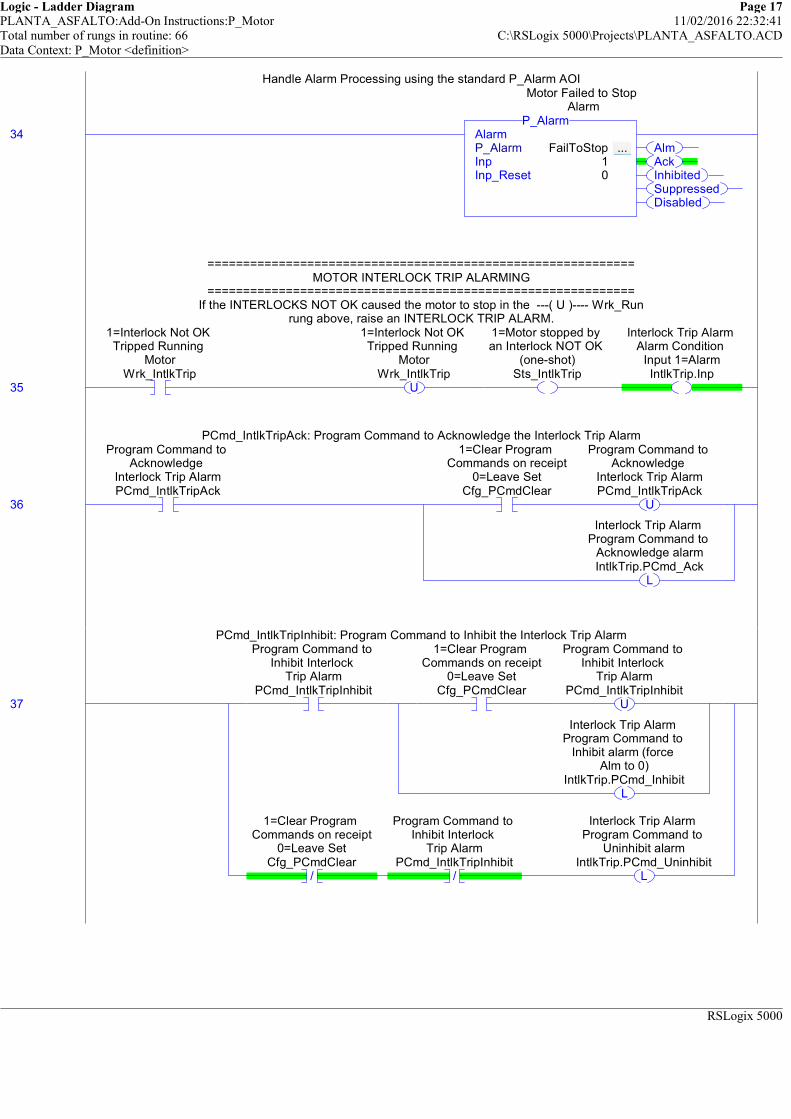
Logic - Ladder Diagram Page 17PLANTA_ASFALTO:Add-On Instructions:P_Motor 11/02/2016 22:32:41Total number of rungs in routine: 66 C:\RSLogix 5000\Projects\PLANTA_ASFALTO.ACDData Context: P_Motor <definition>
RSLogix 5000
Handle Alarm Processing using the standard P_Alarm AOI
34AlmAckInhibitedSuppressedDisabled
AlarmP_Alarm FailToStop ... Inp 1Inp_Reset 0
P_Alarm
Motor Failed to Stop Alarm
Handle Alarm Processing using the standard P_Alarm AOI
============================================================MOTOR INTERLOCK TRIP ALARMING
============================================================If the INTERLOCKS NOT OK caused the motor to stop in the ---( U )---- Wrk_Run
rung above, raise an INTERLOCK TRIP ALARM.
35
1=Interlock Not OK Tripped Running
MotorWrk_IntlkTrip
U
1=Interlock Not OK Tripped Running
MotorWrk_IntlkTrip
1=Motor stopped by an Interlock NOT OK
(one-shot)Sts_IntlkTrip
Interlock Trip Alarm Alarm Condition
Input 1=AlarmIntlkTrip.Inp
============================================================MOTOR INTERLOCK TRIP ALARMING
============================================================If the INTERLOCKS NOT OK caused the motor to stop in the ---( U )---- Wrk_Run
rung above, raise an INTERLOCK TRIP ALARM.
PCmd_IntlkTripAck: Program Command to Acknowledge the Interlock Trip Alarm
36
Program Command to Acknowledge
Interlock Trip AlarmPCmd_IntlkTripAck
1=Clear Program Commands on receipt
0=Leave SetCfg_PCmdClear
U
Program Command to Acknowledge
Interlock Trip AlarmPCmd_IntlkTripAck
L
Interlock Trip Alarm Program Command to
Acknowledge alarmIntlkTrip.PCmd_Ack
PCmd_IntlkTripAck: Program Command to Acknowledge the Interlock Trip Alarm
PCmd_IntlkTripInhibit: Program Command to Inhibit the Interlock Trip Alarm
37
Program Command to Inhibit Interlock
Trip AlarmPCmd_IntlkTripInhibit
1=Clear Program Commands on receipt
0=Leave SetCfg_PCmdClear
U
Program Command to Inhibit Interlock
Trip AlarmPCmd_IntlkTripInhibit
L
Interlock Trip Alarm Program Command to
Inhibit alarm (force Alm to 0)
IntlkTrip.PCmd_Inhibit
/
1=Clear Program Commands on receipt
0=Leave SetCfg_PCmdClear
/
Program Command to Inhibit Interlock
Trip AlarmPCmd_IntlkTripInhibit
L
Interlock Trip Alarm Program Command to
Uninhibit alarmIntlkTrip.PCmd_Uninhibit
PCmd_IntlkTripInhibit: Program Command to Inhibit the Interlock Trip Alarm

Logic - Ladder Diagram Page 18PLANTA_ASFALTO:Add-On Instructions:P_Motor 11/02/2016 22:32:41Total number of rungs in routine: 66 C:\RSLogix 5000\Projects\PLANTA_ASFALTO.ACDData Context: P_Motor <definition>
RSLogix 5000
PCmd_IntlkTripUninhibit: Program Command to Uninhibit the Interlock trip Alarm
38
Program Command to Uninhibit Interlock
Trip AlarmPCmd_IntlkTripUninhibit
U
Program Command to Uninhibit Interlock
Trip AlarmPCmd_IntlkTripUninhibit
L
Interlock Trip Alarm Program Command to
Uninhibit alarmIntlkTrip.PCmd_Uninhibit
PCmd_IntlkTripUninhibit: Program Command to Uninhibit the Interlock trip Alarm
Move Alarm configuration data into the P_Alarm Add-On Instruction:
##### V1.1-00 2010-03-18: Added: Exists: Alarm exists and logic must be scanned #####AckReqd: Alarm must be acknowledged
ResetReqd: Alarm latched in, must be cleared via Reset CommandSeverity: 1=Info, 2=Warning, 3=Exception, 4=Equipment Fault
MinDuration: Alarm must stay on at least this long to be seen by HMI poll
39
1=Interlock Trip Alarm exists and will be checked
Cfg_HasIntlkTripAlm
Interlock Trip Alarm 1=Alarm configured to exist, 0=Does not
exist, don't scanIntlkTrip.Cfg_Exists
1=Acknowledge required for
Interlock Trip AlarmCfg_IntlkTripAckReqd
Interlock Trip Alarm 1=Acknowledge
required for AlarmIntlkTrip.Cfg_AckReqd
1=Reset required to clear Interlock Trip
AlarmCfg_IntlkTripResetReqd
Interlock Trip Alarm 1=Reset required to
clear AlarmIntlkTrip.Cfg_ResetReqd
MoveSource Cfg_IntlkTripSeverity
2Dest IntlkTrip.Cfg_Severity
3
MOV
Interlock Trip Alarm 1=Info Only;
2=Warning; 3=Process Exception; 4=Fault
ClearDest IntlkTrip.Cfg_MinDuration
0
CLR
Interlock Trip Alarm Minimum time (sec) Input must stay on to generate Alarm
Move Alarm configuration data into the P_Alarm Add-On Instruction:
##### V1.1-00 2010-03-18: Added: Exists: Alarm exists and logic must be scanned #####AckReqd: Alarm must be acknowledged
ResetReqd: Alarm latched in, must be cleared via Reset CommandSeverity: 1=Info, 2=Warning, 3=Exception, 4=Equipment Fault
MinDuration: Alarm must stay on at least this long to be seen by HMI poll
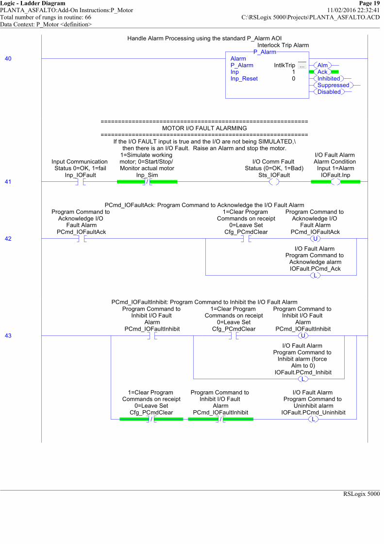
Logic - Ladder Diagram Page 19PLANTA_ASFALTO:Add-On Instructions:P_Motor 11/02/2016 22:32:41Total number of rungs in routine: 66 C:\RSLogix 5000\Projects\PLANTA_ASFALTO.ACDData Context: P_Motor <definition>
RSLogix 5000
Handle Alarm Processing using the standard P_Alarm AOI
40AlmAckInhibitedSuppressedDisabled
AlarmP_Alarm IntlkTrip ... Inp 1Inp_Reset 0
P_AlarmInterlock Trip Alarm
Handle Alarm Processing using the standard P_Alarm AOI
============================================================MOTOR I/O FAULT ALARMING
============================================================If the I/O FAULT input is true and the I/O are not being SIMULATED,\
then there is an I/O Fault. Raise an Alarm and stop the motor.
41
Input Communication Status 0=OK, 1=fail
Inp_IOFault/
1=Simulate working motor; 0=Start/Stop/ Monitor actual motor
Inp_Sim
I/O Comm Fault Status (0=OK, 1=Bad)
Sts_IOFault
I/O Fault Alarm Alarm Condition
Input 1=AlarmIOFault.Inp
============================================================MOTOR I/O FAULT ALARMING
============================================================If the I/O FAULT input is true and the I/O are not being SIMULATED,\
then there is an I/O Fault. Raise an Alarm and stop the motor.
PCmd_IOFaultAck: Program Command to Acknowledge the I/O Fault Alarm
42
Program Command to Acknowledge I/O
Fault AlarmPCmd_IOFaultAck
1=Clear Program Commands on receipt
0=Leave SetCfg_PCmdClear
U
Program Command to Acknowledge I/O
Fault AlarmPCmd_IOFaultAck
L
I/O Fault Alarm Program Command to
Acknowledge alarmIOFault.PCmd_Ack
PCmd_IOFaultAck: Program Command to Acknowledge the I/O Fault Alarm
PCmd_IOFaultInhibit: Program Command to Inhibit the I/O Fault Alarm
43
Program Command to Inhibit I/O Fault
AlarmPCmd_IOFaultInhibit
1=Clear Program Commands on receipt
0=Leave SetCfg_PCmdClear
U
Program Command to Inhibit I/O Fault
AlarmPCmd_IOFaultInhibit
L
I/O Fault Alarm Program Command to
Inhibit alarm (force Alm to 0)
IOFault.PCmd_Inhibit
/
1=Clear Program Commands on receipt
0=Leave SetCfg_PCmdClear
/
Program Command to Inhibit I/O Fault
AlarmPCmd_IOFaultInhibit
L
I/O Fault Alarm Program Command to
Uninhibit alarmIOFault.PCmd_Uninhibit
PCmd_IOFaultInhibit: Program Command to Inhibit the I/O Fault Alarm

Logic - Ladder Diagram Page 20PLANTA_ASFALTO:Add-On Instructions:P_Motor 11/02/2016 22:32:41Total number of rungs in routine: 66 C:\RSLogix 5000\Projects\PLANTA_ASFALTO.ACDData Context: P_Motor <definition>
RSLogix 5000
PCmd_IOFaultUninhibit: Program Command to Uninhibit the I/O Fault Alarm
44
Program Command to Uninhibit I/O Fault
AlarmPCmd_IOFaultUninhibit
U
Program Command to Uninhibit I/O Fault
AlarmPCmd_IOFaultUninhibit
L
I/O Fault Alarm Program Command to
Uninhibit alarmIOFault.PCmd_Uninhibit
PCmd_IOFaultUninhibit: Program Command to Uninhibit the I/O Fault Alarm
Move Alarm configuration data into the P_Alarm Add-On Instruction:
##### V1.1-00 2010-03-18: Added: Exists: Alarm exists and logic must be scanned #####AckReqd: Alarm must be acknowledged
ResetReqd: Alarm latched in, must be cleared via Reset CommandSeverity: 1=Info, 2=Warning, 3=Exception, 4=Equipment Fault
MinDuration: Alarm must stay on at least this long to be seen by HMI poll
45
1=I/O Fault Alarm exists and will be
checkedCfg_HasIOFaultAlm
I/O Fault Alarm 1=Alarm configured to exist, 0=Does not
exist, don't scanIOFault.Cfg_Exists
1=Acknowledge required for I/O
Fault AlarmCfg_IOFaultAckReqd
I/O Fault Alarm 1=Acknowledge
required for AlarmIOFault.Cfg_AckReqd
1=Reset required to clear I/O Fault
AlarmCfg_IOFaultResetReqd
I/O Fault Alarm 1=Reset required to
clear AlarmIOFault.Cfg_ResetReqd
MoveSource Cfg_IOFaultSeverity
4Dest IOFault.Cfg_Severity
3
MOV
I/O Fault Alarm 1=Info Only;
2=Warning; 3=Process Exception; 4=Fault
ClearDest IOFault.Cfg_MinDuration
0
CLR
I/O Fault Alarm Minimum time (sec) Input must stay on to generate Alarm
Move Alarm configuration data into the P_Alarm Add-On Instruction:
##### V1.1-00 2010-03-18: Added: Exists: Alarm exists and logic must be scanned #####AckReqd: Alarm must be acknowledged
ResetReqd: Alarm latched in, must be cleared via Reset CommandSeverity: 1=Info, 2=Warning, 3=Exception, 4=Equipment Fault
MinDuration: Alarm must stay on at least this long to be seen by HMI poll

Logic - Ladder Diagram Page 21PLANTA_ASFALTO:Add-On Instructions:P_Motor 11/02/2016 22:32:41Total number of rungs in routine: 66 C:\RSLogix 5000\Projects\PLANTA_ASFALTO.ACDData Context: P_Motor <definition>
RSLogix 5000
Handle Alarm Processing using the standard P_Alarm AOI
46AlmAckInhibitedSuppressedDisabled
AlarmP_Alarm IOFault ... Inp 1Inp_Reset 0
P_AlarmI/O Fault Alarm
Handle Alarm Processing using the standard P_Alarm AOI
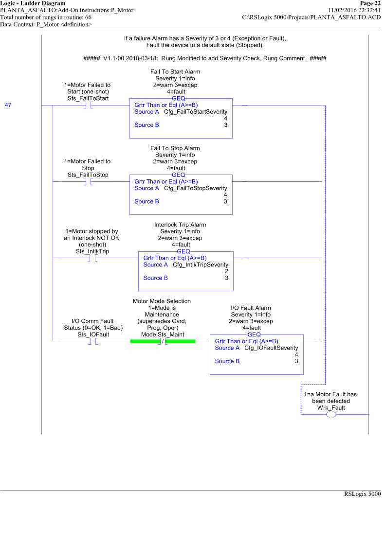
Logic - Ladder Diagram Page 22PLANTA_ASFALTO:Add-On Instructions:P_Motor 11/02/2016 22:32:41Total number of rungs in routine: 66 C:\RSLogix 5000\Projects\PLANTA_ASFALTO.ACDData Context: P_Motor <definition>
RSLogix 5000
If a failure Alarm has a Severity of 3 or 4 (Exception or Fault),Fault the device to a default state (Stopped).
##### V1.1-00 2010-03-18: Rung Modified to add Severity Check, Rung Comment. #####
47
1=Motor Failed to Start (one-shot)Sts_FailToStart
Grtr Than or Eql (A>=B)Source A Cfg_FailToStartSeverity
4Source B 3
GEQ
Fail To Start Alarm Severity 1=info
2=warn 3=excep 4=fault
1=Motor Failed to Stop
Sts_FailToStopGrtr Than or Eql (A>=B)Source A Cfg_FailToStopSeverity
4Source B 3
GEQ
Fail To Stop Alarm Severity 1=info
2=warn 3=excep 4=fault
1=Motor stopped by an Interlock NOT OK
(one-shot)Sts_IntlkTrip
Grtr Than or Eql (A>=B)Source A Cfg_IntlkTripSeverity
2Source B 3
GEQ
Interlock Trip Alarm Severity 1=info
2=warn 3=excep 4=fault
I/O Comm Fault Status (0=OK, 1=Bad)
Sts_IOFault/
Motor Mode Selection 1=Mode is
Maintenance (supersedes Ovrd,
Prog, Oper)Mode.Sts_Maint
Grtr Than or Eql (A>=B)Source A Cfg_IOFaultSeverity
4Source B 3
GEQ
I/O Fault Alarm Severity 1=info
2=warn 3=excep 4=fault
1=a Motor Fault has been detected
Wrk_Fault
If a failure Alarm has a Severity of 3 or 4 (Exception or Fault),Fault the device to a default state (Stopped).
##### V1.1-00 2010-03-18: Rung Modified to add Severity Check, Rung Comment. #####

Logic - Ladder Diagram Page 23PLANTA_ASFALTO:Add-On Instructions:P_Motor 11/02/2016 22:32:41Total number of rungs in routine: 66 C:\RSLogix 5000\Projects\PLANTA_ASFALTO.ACDData Context: P_Motor <definition>
RSLogix 5000
============================================================OUTPUT GENERATION
============================================================
If the motor is NOT SIMULATED, generate theappropriate outputs for the motor.
If the motor should be running, is not faulted and not in hardwired control, energice Out_Run.Also, energize Out_Start until we get feedback that the motor is running.
If the motor should be stopped and is not in hardwired control and the feedback shows the motoris NOT stopped, or if the motor is Faulted or Disabled, energize the Out_Stop output to stop the motor.
48 /
1=Simulate working motor; 0=Start/Stop/ Monitor actual motor
Inp_Sim/
1=a Motor Fault has been detected
Wrk_Fault/
Internal Motor is Disabled
Wrk_Disabled
1=Motor should be "running", 0=should
be "stopped"Wrk_Run
1=Run Motor, 0=Stop
/
Run Feedback based on mode, simulation,
etc. 1=runningWrk_RunFdbk
/
1=Motor should be "running", 0=should
be "stopped"Wrk_Run
Run Feedback based on mode, simulation,
etc. 1=runningWrk_RunFdbk
1=a Motor Fault has been detected
Wrk_Fault
Internal Motor is Disabled
Wrk_Disabled
============================================================OUTPUT GENERATION
============================================================
If the motor is NOT SIMULATED, generate theappropriate outputs for the motor.
If the motor should be running, is not faulted and not in hardwired control, energice Out_Run.Also, energize Out_Start until we get feedback that the motor is running.
If the motor should be stopped and is not in hardwired control and the feedback shows the motoris NOT stopped, or if the motor is Faulted or Disabled, energize the Out_Stop output to stop the motor.
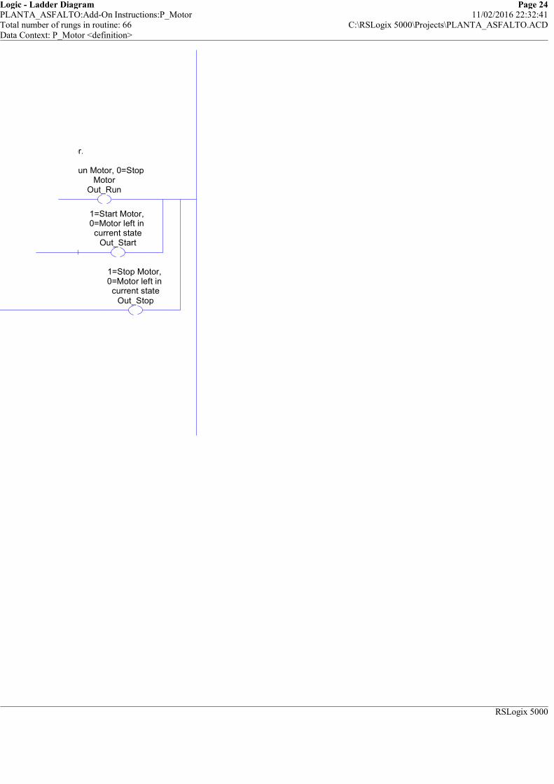
Logic - Ladder Diagram Page 24PLANTA_ASFALTO:Add-On Instructions:P_Motor 11/02/2016 22:32:41Total number of rungs in routine: 66 C:\RSLogix 5000\Projects\PLANTA_ASFALTO.ACDData Context: P_Motor <definition>
RSLogix 5000
is NOT stopped, or if the motor is Faulted or Disabled, energize the Out_Stop output to stop the motor.
1=Run Motor, 0=Stop Motor
Out_Run
1=Start Motor, 0=Motor left in current state
Out_Start
1=Stop Motor, 0=Motor left in current state
Out_Stop
is NOT stopped, or if the motor is Faulted or Disabled, energize the Out_Stop output to stop the motor.

Logic - Ladder Diagram Page 25PLANTA_ASFALTO:Add-On Instructions:P_Motor 11/02/2016 22:32:41Total number of rungs in routine: 66 C:\RSLogix 5000\Projects\PLANTA_ASFALTO.ACDData Context: P_Motor <definition>
RSLogix 5000
============================================================STATUS GENERATION
============================================================
The following rungs generates Status bits for this object.
These Status bits are a copy of the internal Mode AOI bits forHand, Maint, Ovrd, Prog, Oper, and mode Locked.
49
Motor Mode Selection 1=Mode is Hand
(supersedes Maint, Ovrd, Prog, Oper)Mode.Sts_Hand
1=Mode is Hand (supersedes Maint, Ovrd, Prog, Oper)
Sts_Hand
Motor Mode Selection 1=Mode is
Maintenance (supersedes Ovrd,
Prog, Oper)Mode.Sts_Maint
1=Mode is Maintenance
(supersedes Ovrd, Prog, Oper)Sts_Maint
Motor Mode Selection 1=Mode is Override (supersedes Prog,
Oper)Mode.Sts_Ovrd
1=Mode is Override (supersedes Prog,
Oper)Sts_Ovrd
Motor Mode Selection 1=Mode is Program
Mode.Sts_Prog
1=Mode is Program (auto)
Sts_Prog
Motor Mode Selection 1=Mode is Operator
Mode.Sts_Oper
1=Mode is Operator (manual)Sts_Oper
Motor Mode Selection 1=Program or Operator has
requested Mode LockMode.Sts_ProgOperLock
1=Program or Operator has
requested Mode LockSts_ProgOperLock
============================================================STATUS GENERATION
============================================================
The following rungs generates Status bits for this object.
These Status bits are a copy of the internal Mode AOI bits forHand, Maint, Ovrd, Prog, Oper, and mode Locked.

Logic - Ladder Diagram Page 26PLANTA_ASFALTO:Add-On Instructions:P_Motor 11/02/2016 22:32:41Total number of rungs in routine: 66 C:\RSLogix 5000\Projects\PLANTA_ASFALTO.ACDData Context: P_Motor <definition>
RSLogix 5000
This rung generates a summary Bad Config status, simply an OR of the individual bits provided above(in the Configuration handling section).
50
1=Error in Config: Start/Stop Check
timer preset (use 0 to 2147483)Err_Timer
1=Error in Config: Simulation timer preset (use 0 to
2147483)Err_Sim
Motor Failed to Start Alarm 1=Error
in Config: see detail Err_ bits for
reasonFailToStart.Sts_Err
Motor Failed to Stop Alarm 1=Error in Config: see detail Err_ bits for reasonFailToStop.Sts_Err
Interlock Trip Alarm 1=Error in Config: see detail Err_ bits
for reasonIntlkTrip.Sts_Err
I/O Fault Alarm 1=Error in Config: see detail Err_ bits
for reasonIOFault.Sts_Err
1=Error in Config: Invalid Alarm
SeverityErr_Alarm
1=Error in Config: see detail bits for
reasonSts_Err
This rung generates a summary Bad Config status, simply an OR of the individual bits provided above(in the Configuration handling section).

Logic - Ladder Diagram Page 27PLANTA_ASFALTO:Add-On Instructions:P_Motor 11/02/2016 22:32:41Total number of rungs in routine: 66 C:\RSLogix 5000\Projects\PLANTA_ASFALTO.ACDData Context: P_Motor <definition>
RSLogix 5000
Alarm Status bits are a copy of the internal Alarm AOI Status bits.
51
Motor Failed to Start Alarm Alarm output 1=In AlarmFailToStart.Alm
1=Motor Fail to Start Alarm
Alm_FailToStart
Motor Failed to Start Alarm Alarm
acknowledged status: 1=Ack rcvd
FailToStart.Ack
1=Fail to Start Alarm has been acknowledged
Ack_FailToStart
Motor Failed to Start Alarm 1=Alarm
has been Disabled by Maintanance (will
not be sent)FailToStart.Disabled
1=Fail to Start Alarm has been disabled (will not
be sent)Sts_FailToStartDisabled
Motor Failed to Start Alarm 1=Alarm has been Inhibited
by Program (will not be sent)
FailToStart.Inhibited
1=Fail to Start Alarm has been inhibited by logic
Sts_FailToStartInhibited
Motor Failed to Start Alarm 1=Alarm
has been Suppressed by Operator (not visible on HMI)
FailToStart.Suppressed
1=Fail to Start Alarm has been
suppressed (logged only)
Sts_FailToStartSuppressed
Alarm Status bits are a copy of the internal Alarm AOI Status bits.
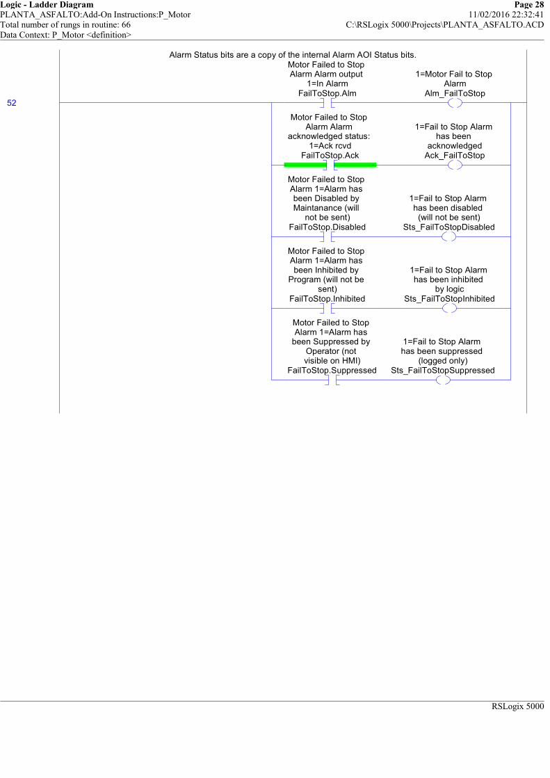
Logic - Ladder Diagram Page 28PLANTA_ASFALTO:Add-On Instructions:P_Motor 11/02/2016 22:32:41Total number of rungs in routine: 66 C:\RSLogix 5000\Projects\PLANTA_ASFALTO.ACDData Context: P_Motor <definition>
RSLogix 5000
Alarm Status bits are a copy of the internal Alarm AOI Status bits.
52
Motor Failed to Stop Alarm Alarm output
1=In AlarmFailToStop.Alm
1=Motor Fail to Stop Alarm
Alm_FailToStop
Motor Failed to Stop Alarm Alarm
acknowledged status: 1=Ack rcvd
FailToStop.Ack
1=Fail to Stop Alarm has been
acknowledgedAck_FailToStop
Motor Failed to Stop Alarm 1=Alarm has been Disabled by Maintanance (will
not be sent)FailToStop.Disabled
1=Fail to Stop Alarm has been disabled
(will not be sent)Sts_FailToStopDisabled
Motor Failed to Stop Alarm 1=Alarm has been Inhibited by
Program (will not be sent)
FailToStop.Inhibited
1=Fail to Stop Alarm has been inhibited
by logicSts_FailToStopInhibited
Motor Failed to Stop Alarm 1=Alarm has
been Suppressed by Operator (not visible on HMI)
FailToStop.Suppressed
1=Fail to Stop Alarm has been suppressed
(logged only)Sts_FailToStopSuppressed
Alarm Status bits are a copy of the internal Alarm AOI Status bits.
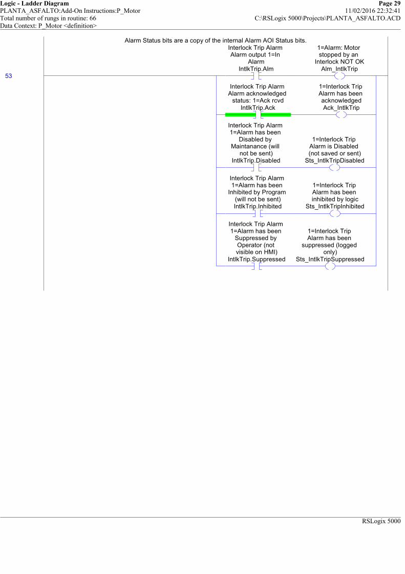
Logic - Ladder Diagram Page 29PLANTA_ASFALTO:Add-On Instructions:P_Motor 11/02/2016 22:32:41Total number of rungs in routine: 66 C:\RSLogix 5000\Projects\PLANTA_ASFALTO.ACDData Context: P_Motor <definition>
RSLogix 5000
Alarm Status bits are a copy of the internal Alarm AOI Status bits.
53
Interlock Trip Alarm Alarm output 1=In
AlarmIntlkTrip.Alm
1=Alarm: Motor stopped by an
Interlock NOT OKAlm_IntlkTrip
Interlock Trip Alarm Alarm acknowledged
status: 1=Ack rcvdIntlkTrip.Ack
1=Interlock Trip Alarm has been acknowledgedAck_IntlkTrip
Interlock Trip Alarm 1=Alarm has been
Disabled by Maintanance (will
not be sent)IntlkTrip.Disabled
1=Interlock Trip Alarm is Disabled (not saved or sent)
Sts_IntlkTripDisabled
Interlock Trip Alarm 1=Alarm has been
Inhibited by Program (will not be sent)IntlkTrip.Inhibited
1=Interlock Trip Alarm has been inhibited by logic
Sts_IntlkTripInhibited
Interlock Trip Alarm 1=Alarm has been
Suppressed by Operator (not visible on HMI)
IntlkTrip.Suppressed
1=Interlock Trip Alarm has been
suppressed (logged only)
Sts_IntlkTripSuppressed
Alarm Status bits are a copy of the internal Alarm AOI Status bits.
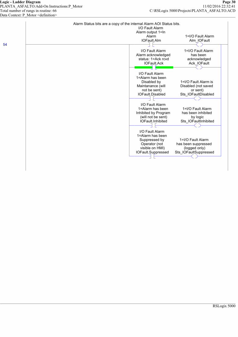
Logic - Ladder Diagram Page 30PLANTA_ASFALTO:Add-On Instructions:P_Motor 11/02/2016 22:32:41Total number of rungs in routine: 66 C:\RSLogix 5000\Projects\PLANTA_ASFALTO.ACDData Context: P_Motor <definition>
RSLogix 5000
Alarm Status bits are a copy of the internal Alarm AOI Status bits.
54
I/O Fault Alarm Alarm output 1=In
AlarmIOFault.Alm
1=I/O Fault AlarmAlm_IOFault
I/O Fault Alarm Alarm acknowledged
status: 1=Ack rcvdIOFault.Ack
1=I/O Fault Alarm has been
acknowledgedAck_IOFault
I/O Fault Alarm 1=Alarm has been
Disabled by Maintanance (will
not be sent)IOFault.Disabled
1=I/O Fault Alarm is Disabled (not saved
or sent)Sts_IOFaultDisabled
I/O Fault Alarm 1=Alarm has been
Inhibited by Program (will not be sent)IOFault.Inhibited
1=I/O Fault Alarm has been inhibited
by logicSts_IOFaultInhibited
I/O Fault Alarm 1=Alarm has been
Suppressed by Operator (not visible on HMI)
IOFault.Suppressed
1=I/O Fault Alarm has been suppressed
(logged only)Sts_IOFaultSuppressed
Alarm Status bits are a copy of the internal Alarm AOI Status bits.
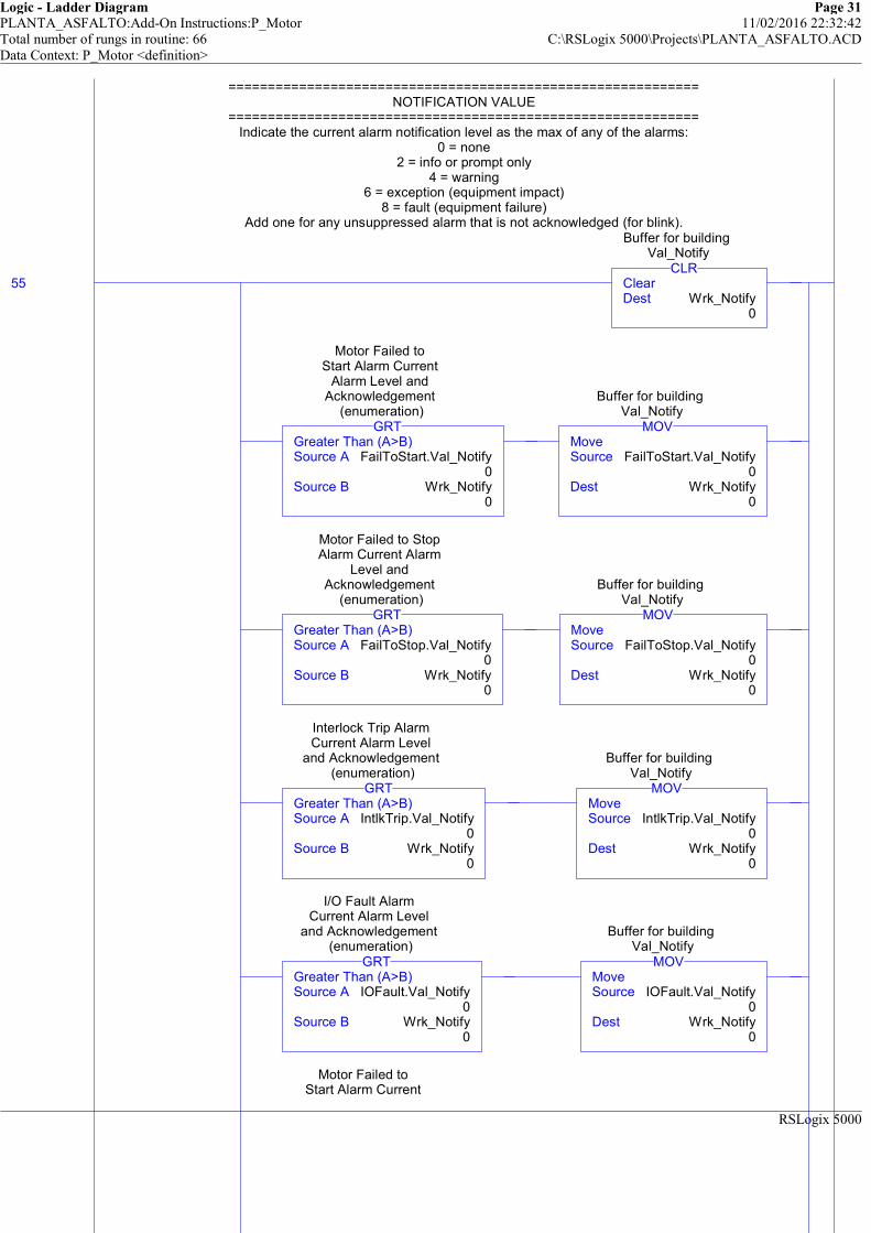
Logic - Ladder Diagram Page 31PLANTA_ASFALTO:Add-On Instructions:P_Motor 11/02/2016 22:32:42Total number of rungs in routine: 66 C:\RSLogix 5000\Projects\PLANTA_ASFALTO.ACDData Context: P_Motor <definition>
RSLogix 5000
============================================================NOTIFICATION VALUE
============================================================Indicate the current alarm notification level as the max of any of the alarms:
0 = none2 = info or prompt only
4 = warning6 = exception (equipment impact)
8 = fault (equipment failure)Add one for any unsuppressed alarm that is not acknowledged (for blink).
55 ClearDest Wrk_Notify
0
CLR
Buffer for building Val_Notify
Greater Than (A>B)Source A FailToStart.Val_Notify
0Source B Wrk_Notify
0
GRT
Motor Failed to Start Alarm Current
Alarm Level and Acknowledgement
(enumeration)
MoveSource FailToStart.Val_Notify
0Dest Wrk_Notify
0
MOV
Buffer for building Val_Notify
Greater Than (A>B)Source A FailToStop.Val_Notify
0Source B Wrk_Notify
0
GRT
Motor Failed to Stop Alarm Current Alarm
Level and Acknowledgement
(enumeration)
MoveSource FailToStop.Val_Notify
0Dest Wrk_Notify
0
MOV
Buffer for building Val_Notify
Greater Than (A>B)Source A IntlkTrip.Val_Notify
0Source B Wrk_Notify
0
GRT
Interlock Trip Alarm Current Alarm Level
and Acknowledgement (enumeration)
MoveSource IntlkTrip.Val_Notify
0Dest Wrk_Notify
0
MOV
Buffer for building Val_Notify
Greater Than (A>B)Source A IOFault.Val_Notify
0Source B Wrk_Notify
0
GRT
I/O Fault Alarm Current Alarm Level
and Acknowledgement (enumeration)
MoveSource IOFault.Val_Notify
0Dest Wrk_Notify
0
MOV
Buffer for building Val_Notify
Motor Failed to Start Alarm Current
============================================================NOTIFICATION VALUE
============================================================Indicate the current alarm notification level as the max of any of the alarms:
0 = none2 = info or prompt only
4 = warning6 = exception (equipment impact)
8 = fault (equipment failure)Add one for any unsuppressed alarm that is not acknowledged (for blink).
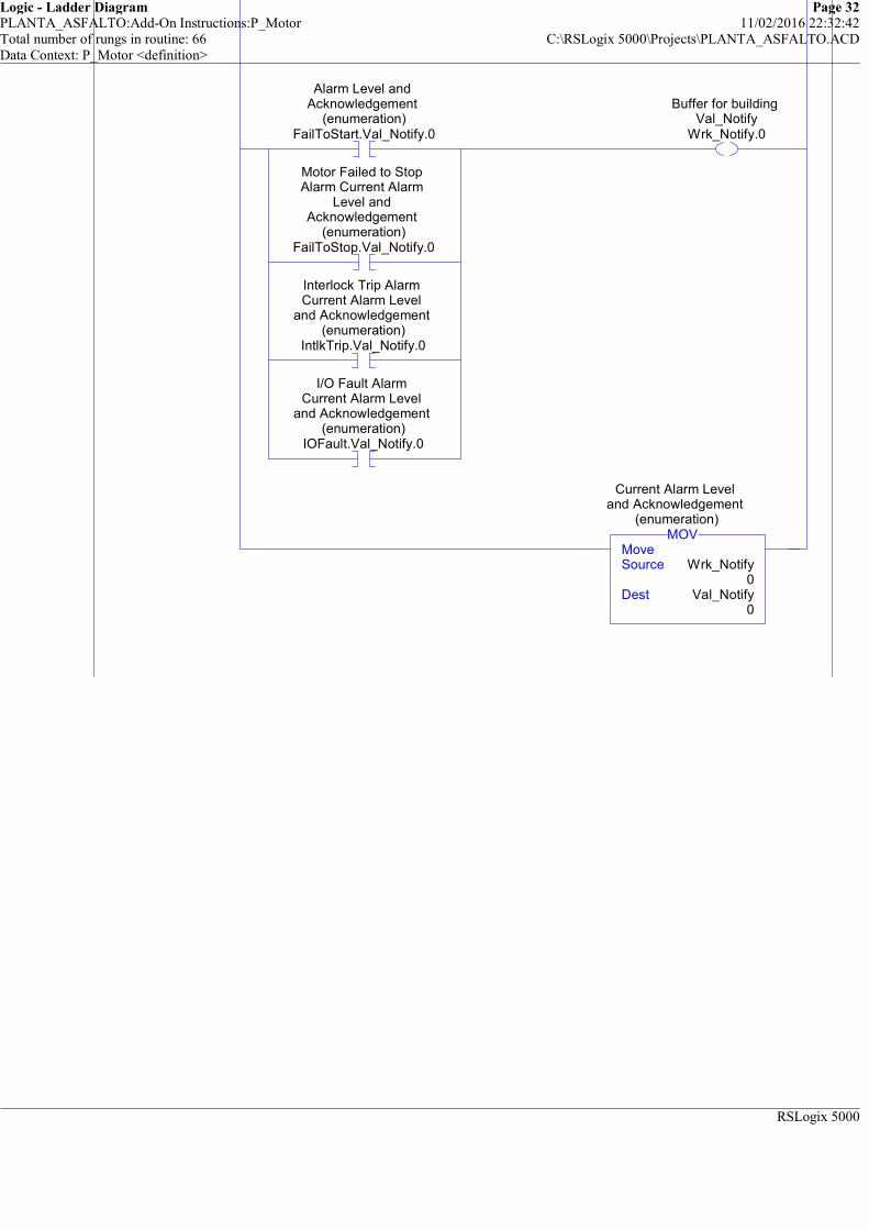
Logic - Ladder Diagram Page 32PLANTA_ASFALTO:Add-On Instructions:P_Motor 11/02/2016 22:32:42Total number of rungs in routine: 66 C:\RSLogix 5000\Projects\PLANTA_ASFALTO.ACDData Context: P_Motor <definition>
RSLogix 5000
Start Alarm Current Alarm Level and
Acknowledgement (enumeration)
FailToStart.Val_Notify.0
Motor Failed to Stop Alarm Current Alarm
Level and Acknowledgement
(enumeration)FailToStop.Val_Notify.0
Interlock Trip Alarm Current Alarm Level
and Acknowledgement (enumeration)
IntlkTrip.Val_Notify.0
I/O Fault Alarm Current Alarm Level
and Acknowledgement (enumeration)
IOFault.Val_Notify.0
Buffer for building Val_Notify
Wrk_Notify.0
MoveSource Wrk_Notify
0Dest Val_Notify
0
MOV
Current Alarm Level and Acknowledgement
(enumeration)
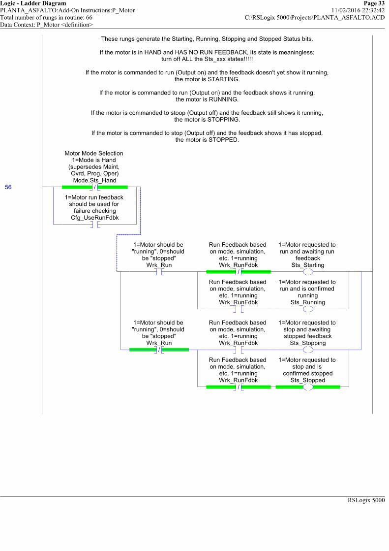
Logic - Ladder Diagram Page 33PLANTA_ASFALTO:Add-On Instructions:P_Motor 11/02/2016 22:32:42Total number of rungs in routine: 66 C:\RSLogix 5000\Projects\PLANTA_ASFALTO.ACDData Context: P_Motor <definition>
RSLogix 5000
These rungs generate the Starting, Running, Stopping and Stopped Status bits.
If the motor is in HAND and HAS NO RUN FEEDBACK, its state is meaningless;turn off ALL the Sts_xxx states!!!!!
If the motor is commanded to run (Output on) and the feedback doesn't yet show it running,the motor is STARTING.
If the motor is commanded to run (Output on) and the feedback shows it running,the motor is RUNNING.
If the motor is commanded to stoop (Output off) and the feedback still shows it running,the motor is STOPPING.
If the motor is commanded to stop (Output off) and the feedback shows it has stopped,the motor is STOPPED.
56 /
Motor Mode Selection 1=Mode is Hand
(supersedes Maint, Ovrd, Prog, Oper)Mode.Sts_Hand
1=Motor run feedback should be used for
failure checkingCfg_UseRunFdbk
1=Motor should be "running", 0=should
be "stopped"Wrk_Run
/
Run Feedback based on mode, simulation,
etc. 1=runningWrk_RunFdbk
1=Motor requested to run and awaiting run
feedbackSts_Starting
Run Feedback based on mode, simulation,
etc. 1=runningWrk_RunFdbk
1=Motor requested to run and is confirmed
runningSts_Running
/
1=Motor should be "running", 0=should
be "stopped"Wrk_Run
Run Feedback based on mode, simulation,
etc. 1=runningWrk_RunFdbk
1=Motor requested to stop and awaiting stopped feedback
Sts_Stopping
/
Run Feedback based on mode, simulation,
etc. 1=runningWrk_RunFdbk
1=Motor requested to stop and is
confirmed stoppedSts_Stopped
These rungs generate the Starting, Running, Stopping and Stopped Status bits.
If the motor is in HAND and HAS NO RUN FEEDBACK, its state is meaningless;turn off ALL the Sts_xxx states!!!!!
If the motor is commanded to run (Output on) and the feedback doesn't yet show it running,the motor is STARTING.
If the motor is commanded to run (Output on) and the feedback shows it running,the motor is RUNNING.
If the motor is commanded to stoop (Output off) and the feedback still shows it running,the motor is STOPPING.
If the motor is commanded to stop (Output off) and the feedback shows it has stopped,the motor is STOPPED.
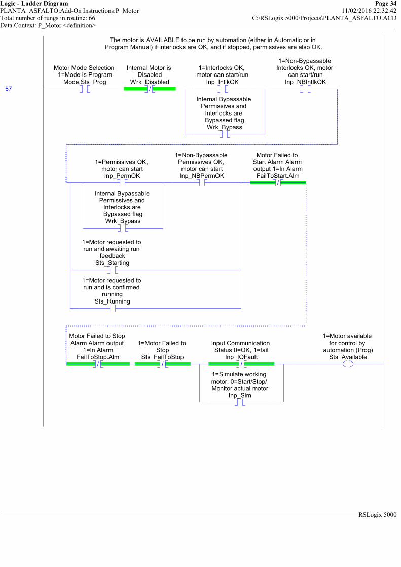
Logic - Ladder Diagram Page 34PLANTA_ASFALTO:Add-On Instructions:P_Motor 11/02/2016 22:32:42Total number of rungs in routine: 66 C:\RSLogix 5000\Projects\PLANTA_ASFALTO.ACDData Context: P_Motor <definition>
RSLogix 5000
The motor is AVAILABLE to be run by automation (either in Automatic or in Program Manual) if interlocks are OK, and if stopped, permissives are also OK.
57
Motor Mode Selection 1=Mode is Program
Mode.Sts_Prog/
Internal Motor is Disabled
Wrk_Disabled
1=Interlocks OK, motor can start/run
Inp_IntlkOK
Internal Bypassable Permissives and
Interlocks are Bypassed flagWrk_Bypass
1=Non-Bypassable Interlocks OK, motor
can start/runInp_NBIntlkOK
1=Permissives OK, motor can startInp_PermOK
Internal Bypassable Permissives and
Interlocks are Bypassed flagWrk_Bypass
1=Non-Bypassable Permissives OK, motor can startInp_NBPermOK
1=Motor requested to run and awaiting run
feedbackSts_Starting
1=Motor requested to run and is confirmed
runningSts_Running
/
Motor Failed to Start Alarm Alarm output 1=In AlarmFailToStart.Alm
/
Motor Failed to Stop Alarm Alarm output
1=In AlarmFailToStop.Alm
/
1=Motor Failed to Stop
Sts_FailToStop/
Input Communication Status 0=OK, 1=fail
Inp_IOFault
1=Simulate working motor; 0=Start/Stop/ Monitor actual motor
Inp_Sim
1=Motor available for control by
automation (Prog)Sts_Available
The motor is AVAILABLE to be run by automation (either in Automatic or in Program Manual) if interlocks are OK, and if stopped, permissives are also OK.

Logic - Ladder Diagram Page 35PLANTA_ASFALTO:Add-On Instructions:P_Motor 11/02/2016 22:32:42Total number of rungs in routine: 66 C:\RSLogix 5000\Projects\PLANTA_ASFALTO.ACDData Context: P_Motor <definition>
RSLogix 5000
##### v1.0-01 2009-07-16: Modified Rung #####
If the internal Bypass flag is set, Bypassable Interlocks and Permissives ARE BYPASSED.Bypassing is ACTIVE if Bypass selected OR in Maintenance Mode,
or in Override Mode if Override Bypassing is configured.
58
Internal Bypassable Permissives and
Interlocks are Bypassed flagWrk_Bypass
1=Bypassable Interlocks and
Permissives are Bypassed
Sts_Bypass
Motor Mode Selection 1=Mode is
Maintenance (supersedes Ovrd,
Prog, Oper)Mode.Sts_Maint
Motor Mode Selection 1=Mode is Override (supersedes Prog,
Oper)Mode.Sts_Ovrd
1=Override ignores Bypassable Perm/ Intlk; 0=always use
Perm/IntlkCfg_OvrdPermIntlk
1=Bypassing Active (Bypassed or Maintenance)Sts_BypActive
##### v1.0-01 2009-07-16: Modified Rung #####
If the internal Bypass flag is set, Bypassable Interlocks and Permissives ARE BYPASSED.Bypassing is ACTIVE if Bypass selected OR in Maintenance Mode,
or in Override Mode if Override Bypassing is configured.
If the internal Disabled flag is set, the motor is DISABLED.
59
Internal Motor is Disabled
Wrk_Disabled1=Motor is Disabled
Sts_Disabled
If the internal Disabled flag is set, the motor is DISABLED.
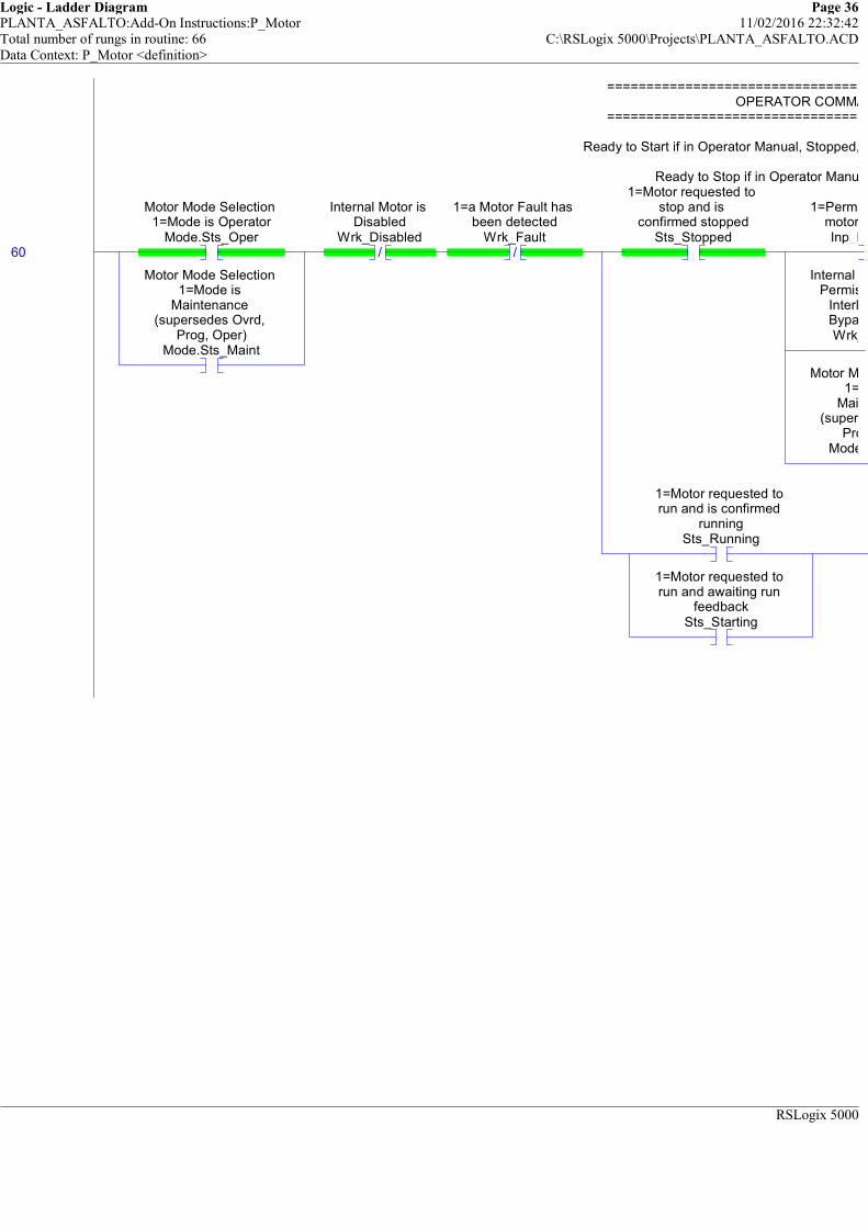
Logic - Ladder Diagram Page 36PLANTA_ASFALTO:Add-On Instructions:P_Motor 11/02/2016 22:32:42Total number of rungs in routine: 66 C:\RSLogix 5000\Projects\PLANTA_ASFALTO.ACDData Context: P_Motor <definition>
RSLogix 5000
============================================================OPERATOR COMMAND READIES
============================================================
Ready to Start if in Operator Manual, Stopped, and Permissives and Interlocks are OK.
Ready to Stop if in Operator Manual and (Running or Starting).
60
Motor Mode Selection 1=Mode is Operator
Mode.Sts_Oper
Motor Mode Selection 1=Mode is
Maintenance (supersedes Ovrd,
Prog, Oper)Mode.Sts_Maint
/
Internal Motor is Disabled
Wrk_Disabled/
1=a Motor Fault has been detected
Wrk_Fault
1=Motor requested to stop and is
confirmed stoppedSts_Stopped
1=Permissives OK, motor can startInp_PermOK
Internal Bypassable Permissives and
Interlocks are Bypassed flagWrk_Bypass
Motor Mode Selection 1=Mode is
Maintenance (supersedes Ovrd,
Prog, Oper)Mode.Sts_Maint
1=Motor requested to run and is confirmed
runningSts_Running
1=Motor requested to run and awaiting run
feedbackSts_Starting
============================================================OPERATOR COMMAND READIES
============================================================
Ready to Start if in Operator Manual, Stopped, and Permissives and Interlocks are OK.
Ready to Stop if in Operator Manual and (Running or Starting).
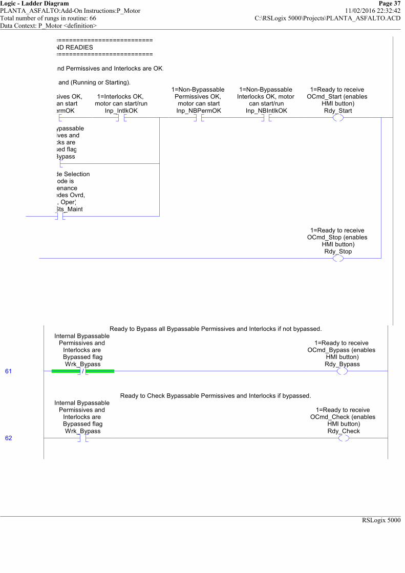
Logic - Ladder Diagram Page 37PLANTA_ASFALTO:Add-On Instructions:P_Motor 11/02/2016 22:32:42Total number of rungs in routine: 66 C:\RSLogix 5000\Projects\PLANTA_ASFALTO.ACDData Context: P_Motor <definition>
RSLogix 5000
============================================================OPERATOR COMMAND READIES
============================================================
Ready to Start if in Operator Manual, Stopped, and Permissives and Interlocks are OK.
Ready to Stop if in Operator Manual and (Running or Starting).
1=Permissives OK, motor can startInp_PermOK
1=Interlocks OK, motor can start/run
Inp_IntlkOK
Internal Bypassable Permissives and
Interlocks are Bypassed flagWrk_Bypass
Motor Mode Selection 1=Mode is
Maintenance (supersedes Ovrd,
Prog, Oper)Mode.Sts_Maint
1=Non-Bypassable Permissives OK, motor can startInp_NBPermOK
1=Non-Bypassable Interlocks OK, motor
can start/runInp_NBIntlkOK
1=Ready to receive OCmd_Start (enables
HMI button)Rdy_Start
1=Ready to receive OCmd_Stop (enables
HMI button)Rdy_Stop
============================================================OPERATOR COMMAND READIES
============================================================
Ready to Start if in Operator Manual, Stopped, and Permissives and Interlocks are OK.
Ready to Stop if in Operator Manual and (Running or Starting).
Ready to Bypass all Bypassable Permissives and Interlocks if not bypassed.
61 /
Internal Bypassable Permissives and
Interlocks are Bypassed flagWrk_Bypass
1=Ready to receive OCmd_Bypass (enables
HMI button)Rdy_Bypass
Ready to Bypass all Bypassable Permissives and Interlocks if not bypassed.
Ready to Check Bypassable Permissives and Interlocks if bypassed.
62
Internal Bypassable Permissives and
Interlocks are Bypassed flagWrk_Bypass
1=Ready to receive OCmd_Check (enables
HMI button)Rdy_Check
Ready to Check Bypassable Permissives and Interlocks if bypassed.

Logic - Ladder Diagram Page 38PLANTA_ASFALTO:Add-On Instructions:P_Motor 11/02/2016 22:32:42Total number of rungs in routine: 66 C:\RSLogix 5000\Projects\PLANTA_ASFALTO.ACDData Context: P_Motor <definition>
RSLogix 5000
Ready to Disable Motor if not Disabled
63 /
Internal Motor is Disabled
Wrk_Disabled
1=Ready to receive MCmd_Disable
(enables HMI button)Rdy_Disable
Ready to Disable Motor if not Disabled
Ready to Enable motor if Disabled.
64
Internal Motor is Disabled
Wrk_Disabled
1=Ready to receive MCmd_Enable (enables
HMI button)Rdy_Enable
Ready to Enable motor if Disabled.
This object requires a Reset if any of its Alarms requires a Reset.
65
Motor Failed to Start Alarm Ready to receive OCmd_Reset
(enable button)FailToStart.Rdy_Reset
Motor Failed to Stop Alarm Ready to
receive OCmd_Reset (enable button)
FailToStop.Rdy_Reset
Interlock Trip Alarm Ready to receive
OCmd_Reset (enable button)
IntlkTrip.Rdy_Reset
I/O Fault Alarm Ready to receive
OCmd_Reset (enable button)
IOFault.Rdy_Reset
1=Ready to receive OCmd_Reset (enables
HMI button)Rdy_Reset
This object requires a Reset if any of its Alarms requires a Reset.
(End)

Logic - Ladder Diagram Page 1PLANTA_ASFALTO:Add-On Instructions:P_ValveSO 11/02/2016 22:33:20Total number of rungs in routine: 73 C:\RSLogix 5000\Projects\PLANTA_ASFALTO.ACDData Context: P_ValveSO <definition>
RSLogix 5000
============================================================P_ValveSO: PROCESS -- SOLENOID OPERATED VALVE
============================================================Revision 1.1-00 - Release: 2010-03-26
* Fixed conditions for Sts_BypActive to include Override Mode (if configured);* (54) Includes updated P_Alarm 1.1-00
* (62) Fixed clearing of Ready (Rdy_) bits in EnableInFalse (Y), Prescan (N)* Fixed handling of Hand mode if NO feedbacks
============================================================This Instruction controls and monitors a single solenoid operated
valve (typ. two position: opened, closed) and provides:
* Support for fail open (energize to close) and fail closed (energize to open, default) valves* Monitoring of limit switch feedback, display of actual valve status
* Detection of failure to move (full stall), failure to reach position (transit stall)* Monitoring of Permissive conditions to allow energizing
* Monitoring of Interlock conditions to de-energize* Simulation, providing feedback of a working valve while disabling outputs
* Monitoring of I/O communication faults* Alarms for Full Stall, Transit Stall, Interlock Trip, I/O Fault
* Operation in Hand, Maintenance, Override, Program and Operator Modes* "Available" status for use by automation logic to know whether valve
can be controlled by other objects.============================================================
POWERUP / INVALID STATE HANDLING============================================================
Mode states are retained through a power cycle.Valve "open" request is set or cleared on first scan; depending on fail state of valve.
============================================================MODE PROCESSING
============================================================These rungs handle received Mode Inputs and Commands:
NOTE: Operator Commands for Mode, Alarm are sent directly to the contained P_Mode and P_Alarm AOIs.
Inp_Hand: forward the Hand Input directly to the Mode instruction.
0
1=Select Hand (hardwired) Mode
Inp_Hand
Valve Mode Selection 1=Select Hand (typ.
hardwired) ModeMode.Inp_Hand
============================================================P_ValveSO: PROCESS -- SOLENOID OPERATED VALVE
============================================================Revision 1.1-00 - Release: 2010-03-26
* Fixed conditions for Sts_BypActive to include Override Mode (if configured);* (54) Includes updated P_Alarm 1.1-00
* (62) Fixed clearing of Ready (Rdy_) bits in EnableInFalse (Y), Prescan (N)* Fixed handling of Hand mode if NO feedbacks
============================================================This Instruction controls and monitors a single solenoid operated
valve (typ. two position: opened, closed) and provides:
* Support for fail open (energize to close) and fail closed (energize to open, default) valves* Monitoring of limit switch feedback, display of actual valve status
* Detection of failure to move (full stall), failure to reach position (transit stall)* Monitoring of Permissive conditions to allow energizing
* Monitoring of Interlock conditions to de-energize* Simulation, providing feedback of a working valve while disabling outputs
* Monitoring of I/O communication faults* Alarms for Full Stall, Transit Stall, Interlock Trip, I/O Fault
* Operation in Hand, Maintenance, Override, Program and Operator Modes* "Available" status for use by automation logic to know whether valve
can be controlled by other objects.============================================================
POWERUP / INVALID STATE HANDLING============================================================
Mode states are retained through a power cycle.Valve "open" request is set or cleared on first scan; depending on fail state of valve.
============================================================MODE PROCESSING
============================================================These rungs handle received Mode Inputs and Commands:
NOTE: Operator Commands for Mode, Alarm are sent directly to the contained P_Mode and P_Alarm AOIs.
Inp_Hand: forward the Hand Input directly to the Mode instruction.
Inp_Ovrd: forward the Override Input directly to the Mode instruction.
1
1=Select Override Mode
Inp_Ovrd
Valve Mode Selection 1=Select Override
(typ. Process/Safety Interlock) ModeMode.Inp_Ovrd
Inp_Ovrd: forward the Override Input directly to the Mode instruction.

Logic - Ladder Diagram Page 2PLANTA_ASFALTO:Add-On Instructions:P_ValveSO 11/02/2016 22:33:29Total number of rungs in routine: 73 C:\RSLogix 5000\Projects\PLANTA_ASFALTO.ACDData Context: P_ValveSO <definition>
RSLogix 5000
PCmd_Acq: Program Command to Acquire ownership
2
Program Command to Acquire ownership
(Oper to Prog)PCmd_Acq
1=Clear Program Commands on receipt
0=Leave SetCfg_PCmdClear
U
Program Command to Acquire ownership
(Oper to Prog)PCmd_Acq
L
Valve Mode Selection Program Command to
Acquire Ownership (Oper to Prog)
Mode.PCmd_Acq
/
Program Command to Acquire ownership
(Oper to Prog)PCmd_Acq
/
1=Clear Program Commands on receipt
0=Leave SetCfg_PCmdClear
U
Valve Mode Selection Program Command to
Acquire Ownership (Oper to Prog)
Mode.PCmd_Acq
PCmd_Acq: Program Command to Acquire ownership
PCmd_Rel: Program Command to Release ownership (to Oper)
3
Program Command to Release ownership
(Prog to Oper)PCmd_Rel
U
Program Command to Release ownership
(Prog to Oper)PCmd_Rel
L
Valve Mode Selection Program Command to Release Ownership
(Prog to Oper)Mode.PCmd_Rel
PCmd_Rel: Program Command to Release ownership (to Oper)
PCmd_Lock: Program Command to Lock ownership in Prog Mode
4
Program Command to Lock Mode in Prog
PCmd_Lock
1=Clear Program Commands on receipt
0=Leave SetCfg_PCmdClear
U
Program Command to Lock Mode in Prog
PCmd_Lock
L
Valve Mode Selection Program Command to
Lock Mode in ProgMode.PCmd_Lock
/
Program Command to Lock Mode in Prog
PCmd_Lock/
1=Clear Program Commands on receipt
0=Leave SetCfg_PCmdClear
U
Valve Mode Selection Program Command to
Lock Mode in ProgMode.PCmd_Lock
PCmd_Lock: Program Command to Lock ownership in Prog Mode
PCmd_Unlock: Program Command to Unlock Mode
5
Program Command to Unlock Mode
PCmd_UnlockU
Program Command to Unlock Mode
PCmd_UnlockL
Valve Mode Selection Program Command to
Unlock ModeMode.PCmd_Unlock
PCmd_Unlock: Program Command to Unlock Mode
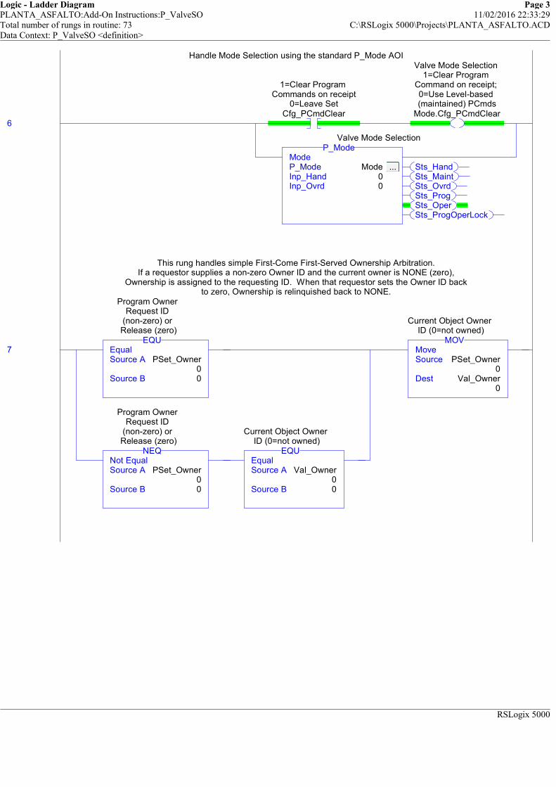
Logic - Ladder Diagram Page 3PLANTA_ASFALTO:Add-On Instructions:P_ValveSO 11/02/2016 22:33:29Total number of rungs in routine: 73 C:\RSLogix 5000\Projects\PLANTA_ASFALTO.ACDData Context: P_ValveSO <definition>
RSLogix 5000
Handle Mode Selection using the standard P_Mode AOI
6
1=Clear Program Commands on receipt
0=Leave SetCfg_PCmdClear
Valve Mode Selection 1=Clear Program
Command on receipt; 0=Use Level-based (maintained) PCmds
Mode.Cfg_PCmdClear
Sts_HandSts_MaintSts_OvrdSts_ProgSts_OperSts_ProgOperLock
ModeP_Mode Mode ... Inp_Hand 0Inp_Ovrd 0
P_ModeValve Mode Selection
Handle Mode Selection using the standard P_Mode AOI
This rung handles simple First-Come First-Served Ownership Arbitration.If a requestor supplies a non-zero Owner ID and the current owner is NONE (zero),
Ownership is assigned to the requesting ID. When that requestor sets the Owner ID backto zero, Ownership is relinquished back to NONE.
7 EqualSource A PSet_Owner
0Source B 0
EQU
Program Owner Request ID
(non-zero) or Release (zero)
Not EqualSource A PSet_Owner
0Source B 0
NEQ
Program Owner Request ID
(non-zero) or Release (zero)
EqualSource A Val_Owner
0Source B 0
EQU
Current Object Owner ID (0=not owned)
MoveSource PSet_Owner
0Dest Val_Owner
0
MOV
Current Object Owner ID (0=not owned)
This rung handles simple First-Come First-Served Ownership Arbitration.If a requestor supplies a non-zero Owner ID and the current owner is NONE (zero),
Ownership is assigned to the requesting ID. When that requestor sets the Owner ID backto zero, Ownership is relinquished back to NONE.

Logic - Ladder Diagram Page 4PLANTA_ASFALTO:Add-On Instructions:P_ValveSO 11/02/2016 22:33:29Total number of rungs in routine: 73 C:\RSLogix 5000\Projects\PLANTA_ASFALTO.ACDData Context: P_ValveSO <definition>
RSLogix 5000
============================================================CONFIGURATION
============================================================
These rungs get Configuration data (such as timer presets) and distribute as needed.Note that some Configuration data are used directly in-place.
Enter the time (in seconds) for the Valve to successfully move from its starting position before declaring a fault.Enter the time (in seconds) for the Valve to successfully reach its target position before declaring a fault.
Enter the time (in seconds) to pulse the valve outputs (Out_Open, Out_Close and Out_Stop)(zero - held on continuously)
If the timer preset calcuated wraps negative (more than 2.14... million seconds), then max out theTimer Preset. Note that a negative timer preset will fault the controller!!!
8 MultiplySource A Cfg_FullStallT
5Source B 1000
Dest Wrk_FullStallT.PRE0
MUL
Timer for Full Stall Check
Less Than (A<B)Source A Wrk_FullStallT.PRE
0Source B 0
LES
Timer for Full Stall Check
MoveSource 2147483647
Dest Wrk_FullStallT.PRE0
MOV
Timer for Full Stall Check
MultiplySource A Cfg_TransitStallT
10Source B 1000
Dest Wrk_TransitStallT.PRE0
MUL
Timer for Transit Stall Check
Less Than (A<B)Source A Wrk_TransitStallT.PRE
0Source B 0
LES
Timer for Transit Stall Check
MoveSource 2147483647
Dest Wrk_TransitStallT.PRE0
MOV
Timer for Transit Stall Check
1=Error in Config: Invalid Check Time (use 0 to 2147483)
Err_Timer
============================================================CONFIGURATION
============================================================
These rungs get Configuration data (such as timer presets) and distribute as needed.Note that some Configuration data are used directly in-place.
Enter the time (in seconds) for the Valve to successfully move from its starting position before declaring a fault.Enter the time (in seconds) for the Valve to successfully reach its target position before declaring a fault.
Enter the time (in seconds) to pulse the valve outputs (Out_Open, Out_Close and Out_Stop)(zero - held on continuously)
If the timer preset calcuated wraps negative (more than 2.14... million seconds), then max out theTimer Preset. Note that a negative timer preset will fault the controller!!!
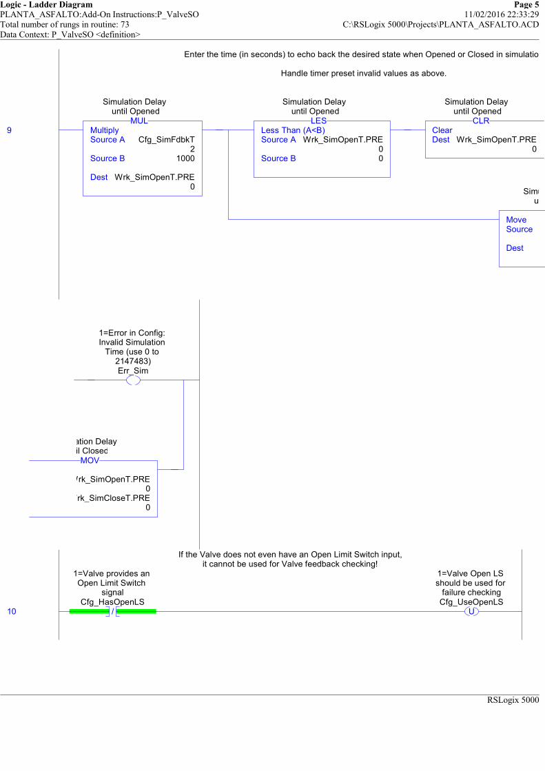
Logic - Ladder Diagram Page 5PLANTA_ASFALTO:Add-On Instructions:P_ValveSO 11/02/2016 22:33:29Total number of rungs in routine: 73 C:\RSLogix 5000\Projects\PLANTA_ASFALTO.ACDData Context: P_ValveSO <definition>
RSLogix 5000
Enter the time (in seconds) to echo back the desired state when Opened or Closed in simulation
Handle timer preset invalid values as above.
9 MultiplySource A Cfg_SimFdbkT
2Source B 1000
Dest Wrk_SimOpenT.PRE0
MUL
Simulation Delay until Opened
Less Than (A<B)Source A Wrk_SimOpenT.PRE
0Source B 0
LES
Simulation Delay until Opened
ClearDest Wrk_SimOpenT.PRE
0
CLR
Simulation Delay until Opened
MoveSource
Dest Wrk_SimCloseT.PRE
Simulation Delay until Closed
Enter the time (in seconds) to echo back the desired state when Opened or Closed in simulation
Handle timer preset invalid values as above.
1=Error in Config: Invalid Simulation
Time (use 0 to 2147483)Err_Sim
Wrk_SimOpenT.PRE0
Wrk_SimCloseT.PRE0
MOV
Simulation Delay until Closed
If the Valve does not even have an Open Limit Switch input,it cannot be used for Valve feedback checking!
10 /
1=Valve provides an Open Limit Switch
signalCfg_HasOpenLS
U
1=Valve Open LS should be used for
failure checkingCfg_UseOpenLS
If the Valve does not even have an Open Limit Switch input,it cannot be used for Valve feedback checking!

Logic - Ladder Diagram Page 6PLANTA_ASFALTO:Add-On Instructions:P_ValveSO 11/02/2016 22:33:29Total number of rungs in routine: 73 C:\RSLogix 5000\Projects\PLANTA_ASFALTO.ACDData Context: P_ValveSO <definition>
RSLogix 5000
If the Valve does not even have a Close Limit Switch input,it cannot be used for Valve feedback checking!
11 /
1=Valve provides a Closed Limit Switch
signalCfg_HasClosedLS
U
1=Valve Closed LS should be used for
failure checkingCfg_UseClosedLS
If the Valve does not even have a Close Limit Switch input,it cannot be used for Valve feedback checking!
============================================================LIMIT SWITCH FEEDBACK DETERMINATION
============================================================If the Valve is being simulated or has no limit switch feedback, use the Sim Timers to provide
"fake" feedback signals based on the simulation time to Open and time to Close.
If the Valve is NOT being simulated and it HAS and IS USING limit switch feedback,use the state of the limit switch feedback inputs as the Valve position.
12
1=Simulate working valve; 0=Open/Close/ Monitor actual valve
Inp_Sim
/
1=Valve Open LS should be used for
failure checkingCfg_UseOpenLS
Simulation Delay until Opened
Wrk_SimOpenT.DN
1=both switches ON=fail, 0=both
switches OFF=failCfg_LSFail
/
Simulation Delay until Closed
Wrk_SimCloseT.DN/
1=both switches ON=fail, 0=both
switches OFF=failCfg_LSFail
/
1=Simulate working valve; 0=Open/Close/ Monitor actual valve
Inp_Sim
1=Valve Open LS should be used for
failure checkingCfg_UseOpenLS
Valve Open Limit Switch 1=confirmed
OPENInp_OpenLS
1=LS Feedback shows valve confirmed open
Wrk_OpenFdbk
============================================================LIMIT SWITCH FEEDBACK DETERMINATION
============================================================If the Valve is being simulated or has no limit switch feedback, use the Sim Timers to provide
"fake" feedback signals based on the simulation time to Open and time to Close.
If the Valve is NOT being simulated and it HAS and IS USING limit switch feedback,use the state of the limit switch feedback inputs as the Valve position.

Logic - Ladder Diagram Page 7PLANTA_ASFALTO:Add-On Instructions:P_ValveSO 11/02/2016 22:33:29Total number of rungs in routine: 73 C:\RSLogix 5000\Projects\PLANTA_ASFALTO.ACDData Context: P_ValveSO <definition>
RSLogix 5000
If the Valve is being simulated or has no limit switch feedback, use the Sim Timers to provide"fake" feedback signals based on the simulation time to Open and time to Close.
If the Valve is NOT being simulated and it HAS and IS USING limit switch feedback,use the state of the limit switch feedback inputs as the Valve position.
13
1=Simulate working valve; 0=Open/Close/ Monitor actual valve
Inp_Sim
/
1=Valve Closed LS should be used for
failure checkingCfg_UseClosedLS
Simulation Delay until Closed
Wrk_SimCloseT.DN
1=both switches ON=fail, 0=both
switches OFF=failCfg_LSFail
/
Simulation Delay until Opened
Wrk_SimOpenT.DN/
1=both switches ON=fail, 0=both
switches OFF=failCfg_LSFail
/
1=Simulate working valve; 0=Open/Close/ Monitor actual valve
Inp_Sim
1=Valve Closed LS should be used for
failure checkingCfg_UseClosedLS
Valve Closed Limit Switch 1=confirmed
CLOSEDInp_ClosedLS
1=LS Feedback shows valve confirmed
closedWrk_ClosedFdbk
If the Valve is being simulated or has no limit switch feedback, use the Sim Timers to provide"fake" feedback signals based on the simulation time to Open and time to Close.
If the Valve is NOT being simulated and it HAS and IS USING limit switch feedback,use the state of the limit switch feedback inputs as the Valve position.
The valve can be configured to have Limit Switch Failure shown for bothlimit switches ON or for both switches OFF.
14
1=both switches ON=fail, 0=both
switches OFF=failCfg_LSFail
1=LS Feedback shows valve confirmed open
Wrk_OpenFdbk
1=LS Feedback shows valve confirmed
closedWrk_ClosedFdbk
/
1=both switches ON=fail, 0=both
switches OFF=failCfg_LSFail
/
1=LS Feedback shows valve confirmed open
Wrk_OpenFdbk/
1=LS Feedback shows valve confirmed
closedWrk_ClosedFdbk
1=LS Feedback shows Limit Switch Failure
Wrk_LSFailFdbk
The valve can be configured to have Limit Switch Failure shown for bothlimit switches ON or for both switches OFF.
The OTHER (non-failure) state with both switches ON or both switches OFF isvalve IN TRANSIT.
15
1=both switches ON=fail, 0=both
switches OFF=failCfg_LSFail
/
1=LS Feedback shows valve confirmed open
Wrk_OpenFdbk/
1=LS Feedback shows valve confirmed
closedWrk_ClosedFdbk
/
1=both switches ON=fail, 0=both
switches OFF=failCfg_LSFail
1=LS Feedback shows valve confirmed open
Wrk_OpenFdbk
1=LS Feedback shows valve confirmed
closedWrk_ClosedFdbk
1=LS Feedback shows Valve is TravelingWrk_TravelFdbk
The OTHER (non-failure) state with both switches ON or both switches OFF isvalve IN TRANSIT.
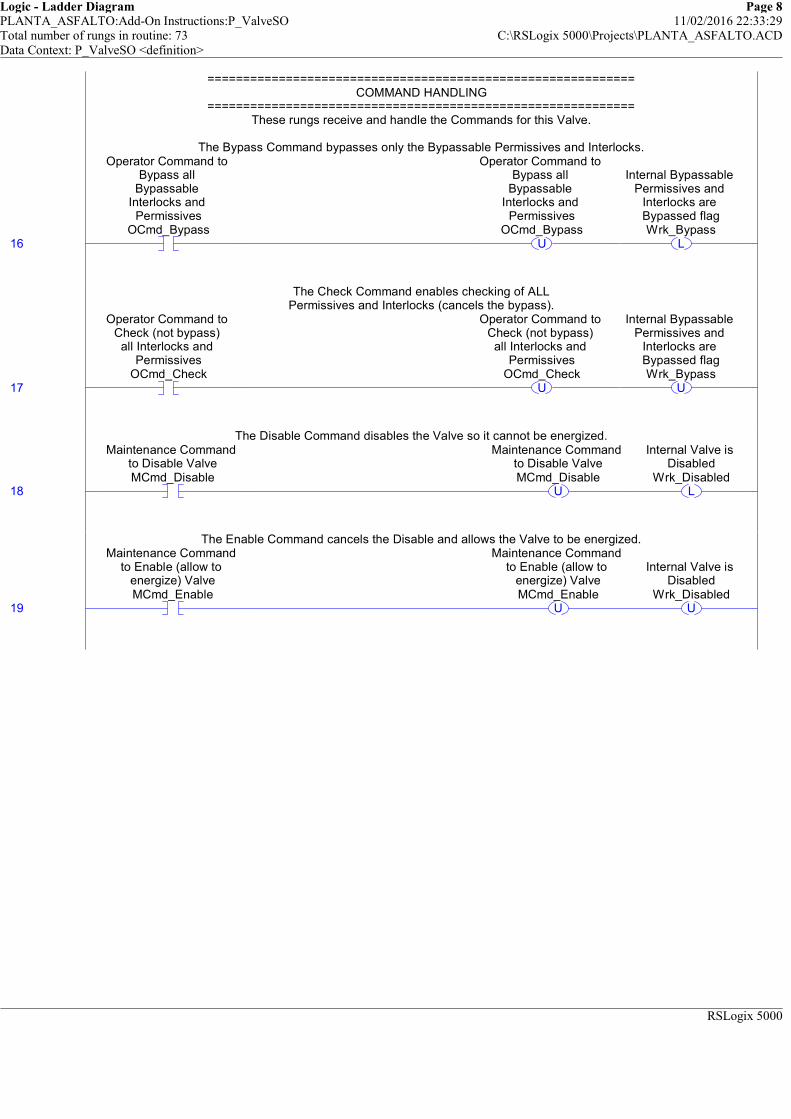
Logic - Ladder Diagram Page 8PLANTA_ASFALTO:Add-On Instructions:P_ValveSO 11/02/2016 22:33:29Total number of rungs in routine: 73 C:\RSLogix 5000\Projects\PLANTA_ASFALTO.ACDData Context: P_ValveSO <definition>
RSLogix 5000
============================================================COMMAND HANDLING
============================================================These rungs receive and handle the Commands for this Valve.
The Bypass Command bypasses only the Bypassable Permissives and Interlocks.
16
Operator Command to Bypass all
Bypassable Interlocks and
PermissivesOCmd_Bypass
U
Operator Command to Bypass all
Bypassable Interlocks and
PermissivesOCmd_Bypass
L
Internal Bypassable Permissives and
Interlocks are Bypassed flagWrk_Bypass
============================================================COMMAND HANDLING
============================================================These rungs receive and handle the Commands for this Valve.
The Bypass Command bypasses only the Bypassable Permissives and Interlocks.
The Check Command enables checking of ALLPermissives and Interlocks (cancels the bypass).
17
Operator Command to Check (not bypass) all Interlocks and
PermissivesOCmd_Check
U
Operator Command to Check (not bypass) all Interlocks and
PermissivesOCmd_Check
U
Internal Bypassable Permissives and
Interlocks are Bypassed flagWrk_Bypass
The Check Command enables checking of ALLPermissives and Interlocks (cancels the bypass).
The Disable Command disables the Valve so it cannot be energized.
18
Maintenance Command to Disable ValveMCmd_Disable
U
Maintenance Command to Disable ValveMCmd_Disable
L
Internal Valve is Disabled
Wrk_Disabled
The Disable Command disables the Valve so it cannot be energized.
The Enable Command cancels the Disable and allows the Valve to be energized.
19
Maintenance Command to Enable (allow to
energize) ValveMCmd_Enable
U
Maintenance Command to Enable (allow to
energize) ValveMCmd_Enable
U
Internal Valve is Disabled
Wrk_Disabled
The Enable Command cancels the Disable and allows the Valve to be energized.
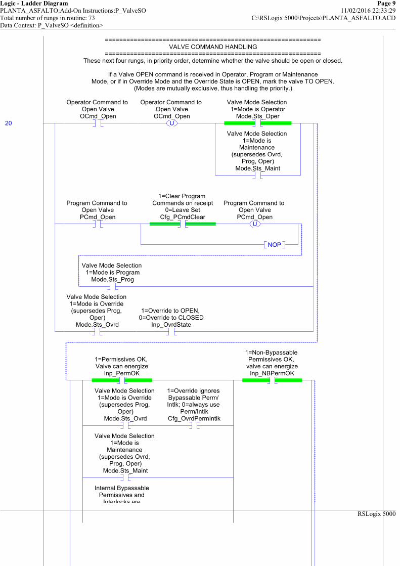
Logic - Ladder Diagram Page 9PLANTA_ASFALTO:Add-On Instructions:P_ValveSO 11/02/2016 22:33:29Total number of rungs in routine: 73 C:\RSLogix 5000\Projects\PLANTA_ASFALTO.ACDData Context: P_ValveSO <definition>
RSLogix 5000
============================================================VALVE COMMAND HANDLING
============================================================These next four rungs, in priority order, determine whether the valve should be open or closed.
If a Valve OPEN command is received in Operator, Program or MaintenanceMode, or if in Override Mode and the Override State is OPEN, mark the valve TO OPEN.
(Modes are mutually exclusive, thus handling the priority.)
20
Operator Command to Open Valve
OCmd_OpenU
Operator Command to Open Valve
OCmd_Open
Valve Mode Selection 1=Mode is Operator
Mode.Sts_Oper
Valve Mode Selection 1=Mode is
Maintenance (supersedes Ovrd,
Prog, Oper)Mode.Sts_Maint
Program Command to Open Valve
PCmd_Open
1=Clear Program Commands on receipt
0=Leave SetCfg_PCmdClear
U
Program Command to Open Valve
PCmd_Open
NOP
Valve Mode Selection 1=Mode is Program
Mode.Sts_Prog
Valve Mode Selection 1=Mode is Override (supersedes Prog,
Oper)Mode.Sts_Ovrd
1=Override to OPEN, 0=Override to CLOSED
Inp_OvrdState
1=Permissives OK, Valve can energize
Inp_PermOK
Valve Mode Selection 1=Mode is Override (supersedes Prog,
Oper)Mode.Sts_Ovrd
1=Override ignores Bypassable Perm/ Intlk; 0=always use
Perm/IntlkCfg_OvrdPermIntlk
Valve Mode Selection 1=Mode is
Maintenance (supersedes Ovrd,
Prog, Oper)Mode.Sts_Maint
Internal Bypassable Permissives and
Interlocks are
1=Non-Bypassable Permissives OK,
valve can energizeInp_NBPermOK
============================================================VALVE COMMAND HANDLING
============================================================These next four rungs, in priority order, determine whether the valve should be open or closed.
If a Valve OPEN command is received in Operator, Program or MaintenanceMode, or if in Override Mode and the Override State is OPEN, mark the valve TO OPEN.
(Modes are mutually exclusive, thus handling the priority.)

Logic - Ladder Diagram Page 10PLANTA_ASFALTO:Add-On Instructions:P_ValveSO 11/02/2016 22:33:29Total number of rungs in routine: 73 C:\RSLogix 5000\Projects\PLANTA_ASFALTO.ACDData Context: P_ValveSO <definition>
RSLogix 5000
Interlocks are Bypassed flagWrk_Bypass
1=Fail Open (energize to close),
0=Fail Closed (energize to open)
Cfg_FailOpen
L
1=Requested to OPEN Valve, 0=Requested
to CLOSE ValveWrk_Open
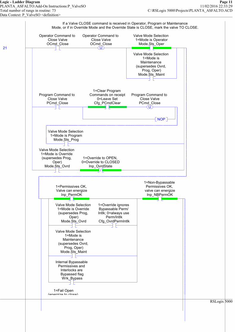
Logic - Ladder Diagram Page 11PLANTA_ASFALTO:Add-On Instructions:P_ValveSO 11/02/2016 22:33:29Total number of rungs in routine: 73 C:\RSLogix 5000\Projects\PLANTA_ASFALTO.ACDData Context: P_ValveSO <definition>
RSLogix 5000
If a Valve CLOSE command is received in Operator, Program or MaintenanceMode, or if in Override Mode and the Override State is CLOSE, mark the valve TO CLOSE.
21
Operator Command to Close Valve
OCmd_CloseU
Operator Command to Close Valve
OCmd_Close
Valve Mode Selection 1=Mode is Operator
Mode.Sts_Oper
Valve Mode Selection 1=Mode is
Maintenance (supersedes Ovrd,
Prog, Oper)Mode.Sts_Maint
Program Command to Close Valve
PCmd_Close
1=Clear Program Commands on receipt
0=Leave SetCfg_PCmdClear
U
Program Command to Close ValvePCmd_Close
NOP
Valve Mode Selection 1=Mode is Program
Mode.Sts_Prog
Valve Mode Selection 1=Mode is Override (supersedes Prog,
Oper)Mode.Sts_Ovrd
/
1=Override to OPEN, 0=Override to CLOSED
Inp_OvrdState
1=Permissives OK, Valve can energize
Inp_PermOK
Valve Mode Selection 1=Mode is Override (supersedes Prog,
Oper)Mode.Sts_Ovrd
1=Override ignores Bypassable Perm/ Intlk; 0=always use
Perm/IntlkCfg_OvrdPermIntlk
Valve Mode Selection 1=Mode is
Maintenance (supersedes Ovrd,
Prog, Oper)Mode.Sts_Maint
Internal Bypassable Permissives and
Interlocks are Bypassed flagWrk_Bypass
1=Non-Bypassable Permissives OK,
valve can energizeInp_NBPermOK
1=Fail Open (energize to close),
If a Valve CLOSE command is received in Operator, Program or MaintenanceMode, or if in Override Mode and the Override State is CLOSE, mark the valve TO CLOSE.
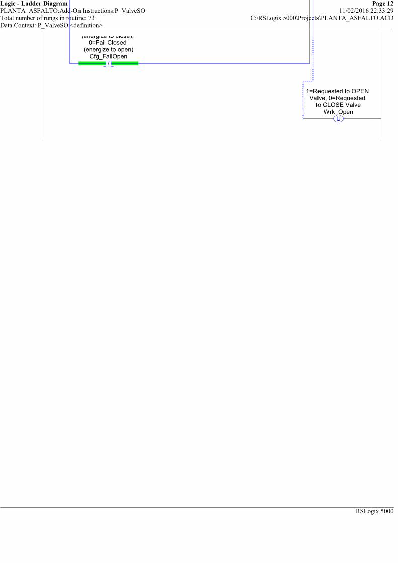
Logic - Ladder Diagram Page 12PLANTA_ASFALTO:Add-On Instructions:P_ValveSO 11/02/2016 22:33:29Total number of rungs in routine: 73 C:\RSLogix 5000\Projects\PLANTA_ASFALTO.ACDData Context: P_ValveSO <definition>
RSLogix 5000
/
(energize to close), 0=Fail Closed
(energize to open)Cfg_FailOpen
U
1=Requested to OPEN Valve, 0=Requested
to CLOSE ValveWrk_Open
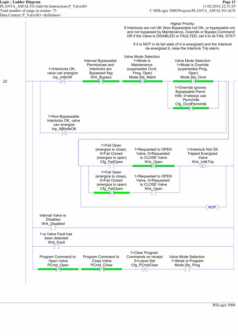
Logic - Ladder Diagram Page 13PLANTA_ASFALTO:Add-On Instructions:P_ValveSO 11/02/2016 22:33:29Total number of rungs in routine: 73 C:\RSLogix 5000\Projects\PLANTA_ASFALTO.ACDData Context: P_ValveSO <definition>
RSLogix 5000
Higher Priority:If Interlocks are not OK (Non-Bypassable not OK, or bypassable not OK
and not bypassed by Maintenance, Override or Bypass Command), OR if the Valve is DISABLED or FAULTED, set it to its FAIL STATE.
If it is NOT in its fail state (if it is energized) and the Interlockde-energized it, raise the Interlock Trip alarm.
22 /
1=Interlocks OK, valve can energize
Inp_IntlkOK/
Internal Bypassable Permissives and
Interlocks are Bypassed flagWrk_Bypass
/
Valve Mode Selection 1=Mode is
Maintenance (supersedes Ovrd,
Prog, Oper)Mode.Sts_Maint
/
Valve Mode Selection 1=Mode is Override (supersedes Prog,
Oper)Mode.Sts_Ovrd
/
1=Override ignores Bypassable Perm/ Intlk; 0=always use
Perm/IntlkCfg_OvrdPermIntlk
/
1=Non-Bypassable Interlocks OK, valve
can energizeInp_NBIntlkOK
1=Fail Open (energize to close),
0=Fail Closed (energize to open)
Cfg_FailOpen/
1=Requested to OPEN Valve, 0=Requested
to CLOSE ValveWrk_Open
/
1=Fail Open (energize to close),
0=Fail Closed (energize to open)
Cfg_FailOpen
1=Requested to OPEN Valve, 0=Requested
to CLOSE ValveWrk_Open
L
1=Interlock Not OK Tripped Energized
ValveWrk_IntlkTrip
NOP
Internal Valve is Disabled
Wrk_Disabled
1=a Valve Fault has been detected
Wrk_Fault
/
Program Command to Open Valve
PCmd_Open/
Program Command to Close Valve
PCmd_Close/
1=Clear Program Commands on receipt
0=Leave SetCfg_PCmdClear
Valve Mode Selection 1=Mode is Program
Mode.Sts_Prog
Higher Priority:If Interlocks are not OK (Non-Bypassable not OK, or bypassable not OK
and not bypassed by Maintenance, Override or Bypass Command), OR if the Valve is DISABLED or FAULTED, set it to its FAIL STATE.
If it is NOT in its fail state (if it is energized) and the Interlockde-energized it, raise the Interlock Trip alarm.

Logic - Ladder Diagram Page 14PLANTA_ASFALTO:Add-On Instructions:P_ValveSO 11/02/2016 22:33:29Total number of rungs in routine: 73 C:\RSLogix 5000\Projects\PLANTA_ASFALTO.ACDData Context: P_ValveSO <definition>
RSLogix 5000
If Interlocks are not OK (Non-Bypassable not OK, or bypassable not OK
1=Fail Open (energize to close),
0=Fail Closed (energize to open)
Cfg_FailOpenL
1=Requested to OPEN Valve, 0=Requested
to CLOSE ValveWrk_Open
/
1=Fail Open (energize to close),
0=Fail Closed (energize to open)
Cfg_FailOpenU
1=Requested to OPEN Valve, 0=Requested
to CLOSE ValveWrk_Open
If Interlocks are not OK (Non-Bypassable not OK, or bypassable not OK

Logic - Ladder Diagram Page 15PLANTA_ASFALTO:Add-On Instructions:P_ValveSO 11/02/2016 22:33:30Total number of rungs in routine: 73 C:\RSLogix 5000\Projects\PLANTA_ASFALTO.ACDData Context: P_ValveSO <definition>
RSLogix 5000
Highest Priority: HAND always wins:If in Hand, have the Valve follow the position feedback.
If the valve is Fail Open, have it set to Open if NOT confirmed FULLY CLOSED.If the valve is Fail Close, have it set to Close if NOT confirmed FULLY OPEN.
23
Valve Mode Selection 1=Mode is Hand
(supersedes Maint, Ovrd, Prog, Oper)Mode.Sts_Hand
1=LS Feedback shows valve confirmed open
Wrk_OpenFdbk
/
1=LS Feedback shows valve confirmed
closedWrk_ClosedFdbk
1=Fail Open (energize to close),
0=Fail Closed (energize to open)
Cfg_FailOpen
L
1=Requested to OPEN Valve, 0=Requested
to CLOSE ValveWrk_Open
1=LS Feedback shows valve confirmed
closedWrk_ClosedFdbk
/
1=LS Feedback shows valve confirmed open
Wrk_OpenFdbk/
1=Fail Open (energize to close),
0=Fail Closed (energize to open)
Cfg_FailOpen
U
1=Requested to OPEN Valve, 0=Requested
to CLOSE ValveWrk_Open
/
1=Valve Open LS should be used for
failure checkingCfg_UseOpenLS
/
1=Valve Closed LS should be used for
failure checkingCfg_UseClosedLS
1=Fail Open (energize to close),
0=Fail Closed (energize to open)
Cfg_FailOpenL
1=Requested to OPEN Valve, 0=Requested
to CLOSE ValveWrk_Open
/
1=Fail Open (energize to close),
0=Fail Closed (energize to open)
Cfg_FailOpenU
1=Requested to OPEN Valve, 0=Requested
to CLOSE ValveWrk_Open
Highest Priority: HAND always wins:If in Hand, have the Valve follow the position feedback.
If the valve is Fail Open, have it set to Open if NOT confirmed FULLY CLOSED.If the valve is Fail Close, have it set to Close if NOT confirmed FULLY OPEN.
Logic - Ladder Diagram Page 16PLANTA_ASFALTO:Add-On Instructions:P_ValveSO 11/02/2016 22:33:30Total number of rungs in routine: 73 C:\RSLogix 5000\Projects\PLANTA_ASFALTO.ACDData Context: P_ValveSO <definition>
RSLogix 5000
1=Requested to OPEN Valve, 0=Requested
to CLOSE ValveWrk_Open
1=Requested to OPEN Valve, 0=Requested
to CLOSE ValveWrk_Open
1=Requested to OPEN Valve, 0=Requested
1=Requested to OPEN Valve, 0=Requested

Logic - Ladder Diagram Page 17PLANTA_ASFALTO:Add-On Instructions:P_ValveSO 11/02/2016 22:33:30Total number of rungs in routine: 73 C:\RSLogix 5000\Projects\PLANTA_ASFALTO.ACDData Context: P_ValveSO <definition>
RSLogix 5000
============================================================ALARM RESET COMMAND HANDLING
============================================================This rung handles the Alarm Reset Commands
24
Program Command to Reset all Alarms requiring ResetPCmd_Reset
1=Clear Program Commands on receipt
0=Leave SetCfg_PCmdClear
U
Program Command to Reset all Alarms requiring ResetPCmd_Reset
NOP
Operator Command to Reset all Alarms requiring ResetOCmd_Reset
U
Operator Command to Reset all Alarms requiring ResetOCmd_Reset
1=Reset all fault conditions and latched Alarms
Inp_Reset
L
Valve Full Stall (did not move) Alarm Program Command to
Reset latched alarmFullStall.PCmd_Reset
L
Valve Transit Stall (moved but did not reach target) Alarm
Program Command to Reset latched alarm
TransitStall.PCmd_ResetL
Interlock Trip Alarm Program Command to
Reset latched alarmIntlkTrip.PCmd_Reset
L
I/O Fault Alarm Program Command to
Reset latched alarmIOFault.PCmd_Reset
============================================================ALARM RESET COMMAND HANDLING
============================================================This rung handles the Alarm Reset Commands
============================================================SIMULATION TIMERS
============================================================If the Valve SHOULD BE Opened, run an Open Simulation Timer.
25
1=Requested to OPEN Valve, 0=Requested
to CLOSE ValveWrk_Open
EN
DN
Timer On DelayTimer Wrk_SimOpenTPreset 0Accum 0
TON
Simulation Delay until Opened
============================================================SIMULATION TIMERS
============================================================If the Valve SHOULD BE Opened, run an Open Simulation Timer.
If the valve SHOULD BE CLosed, run a Close Simulation Timer.
26 /
1=Requested to OPEN Valve, 0=Requested
to CLOSE ValveWrk_Open
EN
DN
Timer On DelayTimer Wrk_SimCloseTPreset 0Accum 0
TON
Simulation Delay until Closed
If the valve SHOULD BE CLosed, run a Close Simulation Timer.
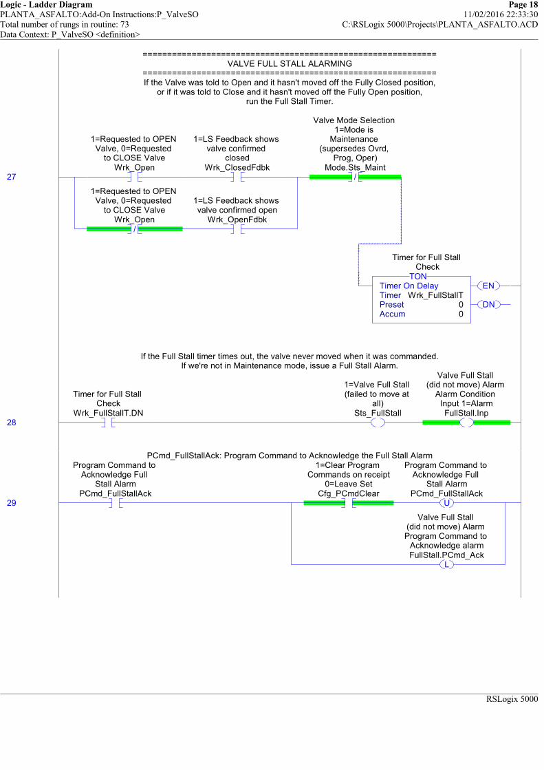
Logic - Ladder Diagram Page 18PLANTA_ASFALTO:Add-On Instructions:P_ValveSO 11/02/2016 22:33:30Total number of rungs in routine: 73 C:\RSLogix 5000\Projects\PLANTA_ASFALTO.ACDData Context: P_ValveSO <definition>
RSLogix 5000
============================================================VALVE FULL STALL ALARMING
============================================================If the Valve was told to Open and it hasn't moved off the Fully Closed position,
or if it was told to Close and it hasn't moved off the Fully Open position,run the Full Stall Timer.
27
1=Requested to OPEN Valve, 0=Requested
to CLOSE ValveWrk_Open
1=LS Feedback shows valve confirmed
closedWrk_ClosedFdbk
/
1=Requested to OPEN Valve, 0=Requested
to CLOSE ValveWrk_Open
1=LS Feedback shows valve confirmed open
Wrk_OpenFdbk
/
Valve Mode Selection 1=Mode is
Maintenance (supersedes Ovrd,
Prog, Oper)Mode.Sts_Maint
EN
DN
Timer On DelayTimer Wrk_FullStallTPreset 0Accum 0
TON
Timer for Full Stall Check
============================================================VALVE FULL STALL ALARMING
============================================================If the Valve was told to Open and it hasn't moved off the Fully Closed position,
or if it was told to Close and it hasn't moved off the Fully Open position,run the Full Stall Timer.
If the Full Stall timer times out, the valve never moved when it was commanded.If we're not in Maintenance mode, issue a Full Stall Alarm.
28
Timer for Full Stall Check
Wrk_FullStallT.DN
1=Valve Full Stall (failed to move at
all)Sts_FullStall
Valve Full Stall (did not move) Alarm
Alarm Condition Input 1=AlarmFullStall.Inp
If the Full Stall timer times out, the valve never moved when it was commanded.If we're not in Maintenance mode, issue a Full Stall Alarm.
PCmd_FullStallAck: Program Command to Acknowledge the Full Stall Alarm
29
Program Command to Acknowledge Full
Stall AlarmPCmd_FullStallAck
1=Clear Program Commands on receipt
0=Leave SetCfg_PCmdClear
U
Program Command to Acknowledge Full
Stall AlarmPCmd_FullStallAck
L
Valve Full Stall (did not move) Alarm Program Command to
Acknowledge alarmFullStall.PCmd_Ack
PCmd_FullStallAck: Program Command to Acknowledge the Full Stall Alarm

Logic - Ladder Diagram Page 19PLANTA_ASFALTO:Add-On Instructions:P_ValveSO 11/02/2016 22:33:30Total number of rungs in routine: 73 C:\RSLogix 5000\Projects\PLANTA_ASFALTO.ACDData Context: P_ValveSO <definition>
RSLogix 5000
PCmd_FullStallInhibit: Program Command to Inhibit the Full Stall Alarm
30
Program Command to Inhibit Full Stall
AlarmPCmd_FullStallInhibit
1=Clear Program Commands on receipt
0=Leave SetCfg_PCmdClear
U
Program Command to Inhibit Full Stall
AlarmPCmd_FullStallInhibit
L
Valve Full Stall (did not move) Alarm Program Command to
Inhibit alarm (force Alm to 0)
FullStall.PCmd_Inhibit
/
1=Clear Program Commands on receipt
0=Leave SetCfg_PCmdClear
/
Program Command to Inhibit Full Stall
AlarmPCmd_FullStallInhibit
L
Valve Full Stall (did not move) Alarm Program Command to
Uninhibit alarmFullStall.PCmd_Uninhibit
PCmd_FullStallInhibit: Program Command to Inhibit the Full Stall Alarm
PCmd_FullStallUninhibit: Program Command to Uninhibit the Full Stall Alarm
31
Program Command to Uninhibit Full Stall
AlarmPCmd_FullStallUninhibit
U
Program Command to Uninhibit Full Stall
AlarmPCmd_FullStallUninhibit
L
Valve Full Stall (did not move) Alarm
Program Command to Uninhibit alarm
FullStall.PCmd_Uninhibit
PCmd_FullStallUninhibit: Program Command to Uninhibit the Full Stall Alarm
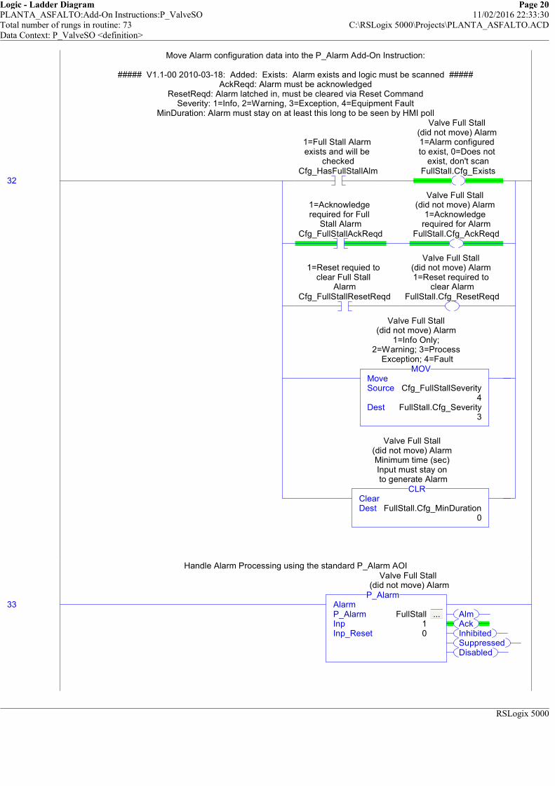
Logic - Ladder Diagram Page 20PLANTA_ASFALTO:Add-On Instructions:P_ValveSO 11/02/2016 22:33:30Total number of rungs in routine: 73 C:\RSLogix 5000\Projects\PLANTA_ASFALTO.ACDData Context: P_ValveSO <definition>
RSLogix 5000
Move Alarm configuration data into the P_Alarm Add-On Instruction:
##### V1.1-00 2010-03-18: Added: Exists: Alarm exists and logic must be scanned #####AckReqd: Alarm must be acknowledged
ResetReqd: Alarm latched in, must be cleared via Reset CommandSeverity: 1=Info, 2=Warning, 3=Exception, 4=Equipment Fault
MinDuration: Alarm must stay on at least this long to be seen by HMI poll
Handle Alarm Processing using the standard P_Alarm AOI
32
1=Full Stall Alarm exists and will be
checkedCfg_HasFullStallAlm
Valve Full Stall (did not move) Alarm 1=Alarm configured to exist, 0=Does not
exist, don't scanFullStall.Cfg_Exists
1=Acknowledge required for Full
Stall AlarmCfg_FullStallAckReqd
Valve Full Stall (did not move) Alarm
1=Acknowledge required for Alarm
FullStall.Cfg_AckReqd
1=Reset requied to clear Full Stall
AlarmCfg_FullStallResetReqd
Valve Full Stall (did not move) Alarm 1=Reset required to
clear AlarmFullStall.Cfg_ResetReqd
MoveSource Cfg_FullStallSeverity
4Dest FullStall.Cfg_Severity
3
MOV
Valve Full Stall (did not move) Alarm
1=Info Only; 2=Warning; 3=Process
Exception; 4=Fault
ClearDest FullStall.Cfg_MinDuration
0
CLR
Valve Full Stall (did not move) Alarm Minimum time (sec) Input must stay on to generate Alarm
Move Alarm configuration data into the P_Alarm Add-On Instruction:
##### V1.1-00 2010-03-18: Added: Exists: Alarm exists and logic must be scanned #####AckReqd: Alarm must be acknowledged
ResetReqd: Alarm latched in, must be cleared via Reset CommandSeverity: 1=Info, 2=Warning, 3=Exception, 4=Equipment Fault
MinDuration: Alarm must stay on at least this long to be seen by HMI poll
33AlmAckInhibitedSuppressedDisabled
AlarmP_Alarm FullStall ... Inp 1Inp_Reset 0
P_Alarm
Valve Full Stall (did not move) Alarm
Handle Alarm Processing using the standard P_Alarm AOI

Logic - Ladder Diagram Page 21PLANTA_ASFALTO:Add-On Instructions:P_ValveSO 11/02/2016 22:33:30Total number of rungs in routine: 73 C:\RSLogix 5000\Projects\PLANTA_ASFALTO.ACDData Context: P_ValveSO <definition>
RSLogix 5000
============================================================VALVE TRANSIT STALL ALARMING
============================================================If the Valve was told to Open and it hasn't reached fully Open,
or if it was told to Close and it hasn't reached fully Closed,run the Transit Stall Timer.
34
1=Requested to OPEN Valve, 0=Requested
to CLOSE ValveWrk_Open
/
1=LS Feedback shows valve confirmed open
Wrk_OpenFdbk
/
1=Requested to OPEN Valve, 0=Requested
to CLOSE ValveWrk_Open
/
1=LS Feedback shows valve confirmed
closedWrk_ClosedFdbk
/
Valve Mode Selection 1=Mode is
Maintenance (supersedes Ovrd,
Prog, Oper)Mode.Sts_Maint
EN
DN
Timer On DelayTimer Wrk_TransitStallTPreset 0Accum 0
TON
Timer for Transit Stall Check
============================================================VALVE TRANSIT STALL ALARMING
============================================================If the Valve was told to Open and it hasn't reached fully Open,
or if it was told to Close and it hasn't reached fully Closed,run the Transit Stall Timer.
If the Transit Stall timer times out and we're not in Maintenance Mode,raise an Alarm for Transit Stall (valve moved but did not reach target).
35
Timer for Transit Stall Check
Wrk_TransitStallT.DN
1=Valve Transit Stall (did not reach
target position)Sts_TransitStall
Valve Transit Stall (moved but did not reach target) Alarm
Alarm Condition Input 1=AlarmTransitStall.Inp
If the Transit Stall timer times out and we're not in Maintenance Mode,raise an Alarm for Transit Stall (valve moved but did not reach target).
PCmd_TransitStallAck: Program Command to Acknowledge the Transit Stall Alarm
36
Program Command to Acknowledge Transit
Stall AlarmPCmd_TransitStallAck
1=Clear Program Commands on receipt
0=Leave SetCfg_PCmdClear
U
Program Command to Acknowledge Transit
Stall AlarmPCmd_TransitStallAck
L
Valve Transit Stall (moved but did not reach target) Alarm
Program Command to Acknowledge alarm
TransitStall.PCmd_Ack
PCmd_TransitStallAck: Program Command to Acknowledge the Transit Stall Alarm
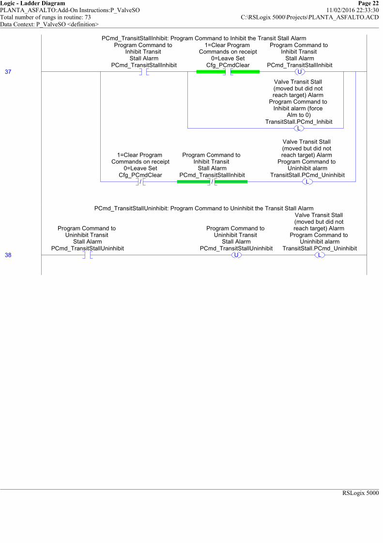
Logic - Ladder Diagram Page 22PLANTA_ASFALTO:Add-On Instructions:P_ValveSO 11/02/2016 22:33:30Total number of rungs in routine: 73 C:\RSLogix 5000\Projects\PLANTA_ASFALTO.ACDData Context: P_ValveSO <definition>
RSLogix 5000
PCmd_TransitStallInhibit: Program Command to Inhibit the Transit Stall Alarm
37
Program Command to Inhibit Transit
Stall AlarmPCmd_TransitStallInhibit
1=Clear Program Commands on receipt
0=Leave SetCfg_PCmdClear
U
Program Command to Inhibit Transit
Stall AlarmPCmd_TransitStallInhibit
L
Valve Transit Stall (moved but did not reach target) Alarm
Program Command to Inhibit alarm (force
Alm to 0)TransitStall.PCmd_Inhibit
/
1=Clear Program Commands on receipt
0=Leave SetCfg_PCmdClear
/
Program Command to Inhibit Transit
Stall AlarmPCmd_TransitStallInhibit
L
Valve Transit Stall (moved but did not reach target) Alarm
Program Command to Uninhibit alarm
TransitStall.PCmd_Uninhibit
PCmd_TransitStallInhibit: Program Command to Inhibit the Transit Stall Alarm
PCmd_TransitStallUninhibit: Program Command to Uninhibit the Transit Stall Alarm
38
Program Command to Uninhibit Transit
Stall AlarmPCmd_TransitStallUninhibit
U
Program Command to Uninhibit Transit
Stall AlarmPCmd_TransitStallUninhibit
L
Valve Transit Stall (moved but did not reach target) Alarm
Program Command to Uninhibit alarm
TransitStall.PCmd_Uninhibit
PCmd_TransitStallUninhibit: Program Command to Uninhibit the Transit Stall Alarm
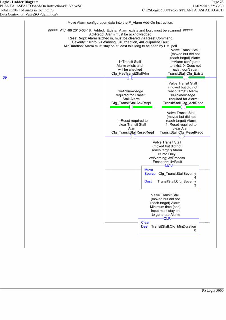
Logic - Ladder Diagram Page 23PLANTA_ASFALTO:Add-On Instructions:P_ValveSO 11/02/2016 22:33:30Total number of rungs in routine: 73 C:\RSLogix 5000\Projects\PLANTA_ASFALTO.ACDData Context: P_ValveSO <definition>
RSLogix 5000
Move Alarm configuration data into the P_Alarm Add-On Instruction:
##### V1.1-00 2010-03-18: Added: Exists: Alarm exists and logic must be scanned #####AckReqd: Alarm must be acknowledged
ResetReqd: Alarm latched in, must be cleared via Reset CommandSeverity: 1=Info, 2=Warning, 3=Exception, 4=Equipment Fault
MinDuration: Alarm must stay on at least this long to be seen by HMI poll
39
1=Transit Stall Alarm exists and will be checked
Cfg_HasTransitStallAlm
Valve Transit Stall (moved but did not reach target) Alarm 1=Alarm configured to exist, 0=Does not
exist, don't scanTransitStall.Cfg_Exists
1=Acknowledge required for Transit
Stall AlarmCfg_TransitStallAckReqd
Valve Transit Stall (moved but did not reach target) Alarm
1=Acknowledge required for Alarm
TransitStall.Cfg_AckReqd
1=Reset required to clear Transit Stall
AlarmCfg_TransitStallResetReqd
Valve Transit Stall (moved but did not reach target) Alarm 1=Reset required to
clear AlarmTransitStall.Cfg_ResetReqd
MoveSource Cfg_TransitStallSeverity
4Dest TransitStall.Cfg_Severity
3
MOV
Valve Transit Stall (moved but did not reach target) Alarm
1=Info Only; 2=Warning; 3=Process
Exception; 4=Fault
ClearDest TransitStall.Cfg_MinDuration
0
CLR
Valve Transit Stall (moved but did not reach target) Alarm Minimum time (sec) Input must stay on to generate Alarm
Move Alarm configuration data into the P_Alarm Add-On Instruction:
##### V1.1-00 2010-03-18: Added: Exists: Alarm exists and logic must be scanned #####AckReqd: Alarm must be acknowledged
ResetReqd: Alarm latched in, must be cleared via Reset CommandSeverity: 1=Info, 2=Warning, 3=Exception, 4=Equipment Fault
MinDuration: Alarm must stay on at least this long to be seen by HMI poll
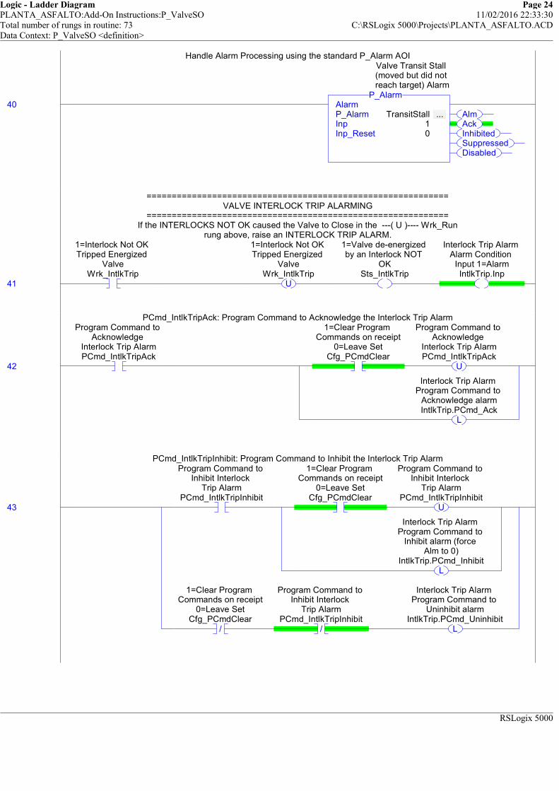
Logic - Ladder Diagram Page 24PLANTA_ASFALTO:Add-On Instructions:P_ValveSO 11/02/2016 22:33:30Total number of rungs in routine: 73 C:\RSLogix 5000\Projects\PLANTA_ASFALTO.ACDData Context: P_ValveSO <definition>
RSLogix 5000
Handle Alarm Processing using the standard P_Alarm AOI
40AlmAckInhibitedSuppressedDisabled
AlarmP_Alarm TransitStall ... Inp 1Inp_Reset 0
P_Alarm
Valve Transit Stall (moved but did not reach target) Alarm
Handle Alarm Processing using the standard P_Alarm AOI
============================================================VALVE INTERLOCK TRIP ALARMING
============================================================If the INTERLOCKS NOT OK caused the Valve to Close in the ---( U )---- Wrk_Run
rung above, raise an INTERLOCK TRIP ALARM.
41
1=Interlock Not OK Tripped Energized
ValveWrk_IntlkTrip
U
1=Interlock Not OK Tripped Energized
ValveWrk_IntlkTrip
1=Valve de-energized by an Interlock NOT
OKSts_IntlkTrip
Interlock Trip Alarm Alarm Condition
Input 1=AlarmIntlkTrip.Inp
============================================================VALVE INTERLOCK TRIP ALARMING
============================================================If the INTERLOCKS NOT OK caused the Valve to Close in the ---( U )---- Wrk_Run
rung above, raise an INTERLOCK TRIP ALARM.
PCmd_IntlkTripAck: Program Command to Acknowledge the Interlock Trip Alarm
42
Program Command to Acknowledge
Interlock Trip AlarmPCmd_IntlkTripAck
1=Clear Program Commands on receipt
0=Leave SetCfg_PCmdClear
U
Program Command to Acknowledge
Interlock Trip AlarmPCmd_IntlkTripAck
L
Interlock Trip Alarm Program Command to
Acknowledge alarmIntlkTrip.PCmd_Ack
PCmd_IntlkTripAck: Program Command to Acknowledge the Interlock Trip Alarm
PCmd_IntlkTripInhibit: Program Command to Inhibit the Interlock Trip Alarm
43
Program Command to Inhibit Interlock
Trip AlarmPCmd_IntlkTripInhibit
1=Clear Program Commands on receipt
0=Leave SetCfg_PCmdClear
U
Program Command to Inhibit Interlock
Trip AlarmPCmd_IntlkTripInhibit
L
Interlock Trip Alarm Program Command to
Inhibit alarm (force Alm to 0)
IntlkTrip.PCmd_Inhibit
/
1=Clear Program Commands on receipt
0=Leave SetCfg_PCmdClear
/
Program Command to Inhibit Interlock
Trip AlarmPCmd_IntlkTripInhibit
L
Interlock Trip Alarm Program Command to
Uninhibit alarmIntlkTrip.PCmd_Uninhibit
PCmd_IntlkTripInhibit: Program Command to Inhibit the Interlock Trip Alarm

Logic - Ladder Diagram Page 25PLANTA_ASFALTO:Add-On Instructions:P_ValveSO 11/02/2016 22:33:30Total number of rungs in routine: 73 C:\RSLogix 5000\Projects\PLANTA_ASFALTO.ACDData Context: P_ValveSO <definition>
RSLogix 5000
PCmd_IntlkTripUninhibit: Program Command to Uninhibit the Interlock trip Alarm
44
Program Command to Uninhibit Interlock
Trip AlarmPCmd_IntlkTripUninhibit
U
Program Command to Uninhibit Interlock
Trip AlarmPCmd_IntlkTripUninhibit
L
Interlock Trip Alarm Program Command to
Uninhibit alarmIntlkTrip.PCmd_Uninhibit
PCmd_IntlkTripUninhibit: Program Command to Uninhibit the Interlock trip Alarm
Move Alarm configuration data into the P_Alarm Add-On Instruction:
##### V1.1-00 2010-03-18: Added: Exists: Alarm exists and logic must be scanned #####AckReqd: Alarm must be acknowledged
ResetReqd: Alarm latched in, must be cleared via Reset CommandSeverity: 1=Info, 2=Warning, 3=Exception, 4=Equipment Fault
MinDuration: Alarm must stay on at least this long to be seen by HMI poll
45
1=Interlock Trip Alarm exists and will be checked
Cfg_HasIntlkTripAlm
Interlock Trip Alarm 1=Alarm configured to exist, 0=Does not
exist, don't scanIntlkTrip.Cfg_Exists
1=Acknowledge required for
Interlock Trip AlarmCfg_IntlkTripAckReqd
Interlock Trip Alarm 1=Acknowledge
required for AlarmIntlkTrip.Cfg_AckReqd
1=Reset required to clear Interlock Trip
AlarmCfg_IntlkTripResetReqd
Interlock Trip Alarm 1=Reset required to
clear AlarmIntlkTrip.Cfg_ResetReqd
MoveSource Cfg_IntlkTripSeverity
2Dest IntlkTrip.Cfg_Severity
3
MOV
Interlock Trip Alarm 1=Info Only;
2=Warning; 3=Process Exception; 4=Fault
ClearDest IntlkTrip.Cfg_MinDuration
0
CLR
Interlock Trip Alarm Minimum time (sec) Input must stay on to generate Alarm
Move Alarm configuration data into the P_Alarm Add-On Instruction:
##### V1.1-00 2010-03-18: Added: Exists: Alarm exists and logic must be scanned #####AckReqd: Alarm must be acknowledged
ResetReqd: Alarm latched in, must be cleared via Reset CommandSeverity: 1=Info, 2=Warning, 3=Exception, 4=Equipment Fault
MinDuration: Alarm must stay on at least this long to be seen by HMI poll

Logic - Ladder Diagram Page 26PLANTA_ASFALTO:Add-On Instructions:P_ValveSO 11/02/2016 22:33:30Total number of rungs in routine: 73 C:\RSLogix 5000\Projects\PLANTA_ASFALTO.ACDData Context: P_ValveSO <definition>
RSLogix 5000
Handle Alarm Processing using the standard P_Alarm AOI
46AlmAckInhibitedSuppressedDisabled
AlarmP_Alarm IntlkTrip ... Inp 1Inp_Reset 0
P_AlarmInterlock Trip Alarm
Handle Alarm Processing using the standard P_Alarm AOI
============================================================VALVE I/O FAULT ALARMING
============================================================If the I/O FAULT input is true and the I/O are not being SIMULATED,\
then there is an I/O Fault. Raise an Alarm and Close the Valve.
47
Input Communication Status 0=OK, 1=fail
Inp_IOFault/
1=Simulate working valve; 0=Open/Close/ Monitor actual valve
Inp_Sim
I/O Comm Fault Status (0=OK, 1=Bad)
Sts_IOFault
I/O Fault Alarm Alarm Condition
Input 1=AlarmIOFault.Inp
============================================================VALVE I/O FAULT ALARMING
============================================================If the I/O FAULT input is true and the I/O are not being SIMULATED,\
then there is an I/O Fault. Raise an Alarm and Close the Valve.
PCmd_IOFaultAck: Program Command to Acknowledge the I/O Fault Alarm
48
Program Command to Acknowledge I/O
Fault AlarmPCmd_IOFaultAck
1=Clear Program Commands on receipt
0=Leave SetCfg_PCmdClear
U
Program Command to Acknowledge I/O
Fault AlarmPCmd_IOFaultAck
L
I/O Fault Alarm Program Command to
Acknowledge alarmIOFault.PCmd_Ack
PCmd_IOFaultAck: Program Command to Acknowledge the I/O Fault Alarm
PCmd_IOFaultInhibit: Program Command to Inhibit the I/O Fault Alarm
49
Program Command to Inhibit I/O Fault
AlarmPCmd_IOFaultInhibit
1=Clear Program Commands on receipt
0=Leave SetCfg_PCmdClear
U
Program Command to Inhibit I/O Fault
AlarmPCmd_IOFaultInhibit
L
I/O Fault Alarm Program Command to
Inhibit alarm (force Alm to 0)
IOFault.PCmd_Inhibit
/
1=Clear Program Commands on receipt
0=Leave SetCfg_PCmdClear
/
Program Command to Inhibit I/O Fault
AlarmPCmd_IOFaultInhibit
L
I/O Fault Alarm Program Command to
Uninhibit alarmIOFault.PCmd_Uninhibit
PCmd_IOFaultInhibit: Program Command to Inhibit the I/O Fault Alarm
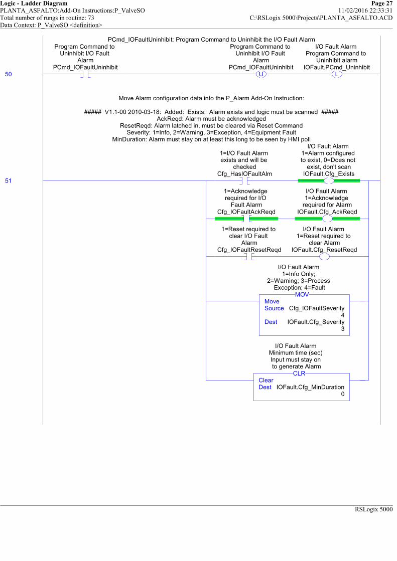
Logic - Ladder Diagram Page 27PLANTA_ASFALTO:Add-On Instructions:P_ValveSO 11/02/2016 22:33:31Total number of rungs in routine: 73 C:\RSLogix 5000\Projects\PLANTA_ASFALTO.ACDData Context: P_ValveSO <definition>
RSLogix 5000
PCmd_IOFaultUninhibit: Program Command to Uninhibit the I/O Fault Alarm
50
Program Command to Uninhibit I/O Fault
AlarmPCmd_IOFaultUninhibit
U
Program Command to Uninhibit I/O Fault
AlarmPCmd_IOFaultUninhibit
L
I/O Fault Alarm Program Command to
Uninhibit alarmIOFault.PCmd_Uninhibit
PCmd_IOFaultUninhibit: Program Command to Uninhibit the I/O Fault Alarm
Move Alarm configuration data into the P_Alarm Add-On Instruction:
##### V1.1-00 2010-03-18: Added: Exists: Alarm exists and logic must be scanned #####AckReqd: Alarm must be acknowledged
ResetReqd: Alarm latched in, must be cleared via Reset CommandSeverity: 1=Info, 2=Warning, 3=Exception, 4=Equipment Fault
MinDuration: Alarm must stay on at least this long to be seen by HMI poll
51
1=I/O Fault Alarm exists and will be
checkedCfg_HasIOFaultAlm
I/O Fault Alarm 1=Alarm configured to exist, 0=Does not
exist, don't scanIOFault.Cfg_Exists
1=Acknowledge required for I/O
Fault AlarmCfg_IOFaultAckReqd
I/O Fault Alarm 1=Acknowledge
required for AlarmIOFault.Cfg_AckReqd
1=Reset required to clear I/O Fault
AlarmCfg_IOFaultResetReqd
I/O Fault Alarm 1=Reset required to
clear AlarmIOFault.Cfg_ResetReqd
MoveSource Cfg_IOFaultSeverity
4Dest IOFault.Cfg_Severity
3
MOV
I/O Fault Alarm 1=Info Only;
2=Warning; 3=Process Exception; 4=Fault
ClearDest IOFault.Cfg_MinDuration
0
CLR
I/O Fault Alarm Minimum time (sec) Input must stay on to generate Alarm
Move Alarm configuration data into the P_Alarm Add-On Instruction:
##### V1.1-00 2010-03-18: Added: Exists: Alarm exists and logic must be scanned #####AckReqd: Alarm must be acknowledged
ResetReqd: Alarm latched in, must be cleared via Reset CommandSeverity: 1=Info, 2=Warning, 3=Exception, 4=Equipment Fault
MinDuration: Alarm must stay on at least this long to be seen by HMI poll

Logic - Ladder Diagram Page 28PLANTA_ASFALTO:Add-On Instructions:P_ValveSO 11/02/2016 22:33:31Total number of rungs in routine: 73 C:\RSLogix 5000\Projects\PLANTA_ASFALTO.ACDData Context: P_ValveSO <definition>
RSLogix 5000
Handle Alarm Processing using the standard P_Alarm AOI
52AlmAckInhibitedSuppressedDisabled
AlarmP_Alarm IOFault ... Inp 1Inp_Reset 0
P_AlarmI/O Fault Alarm
Handle Alarm Processing using the standard P_Alarm AOI
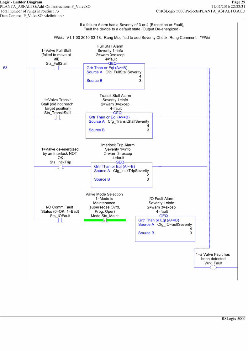
Logic - Ladder Diagram Page 29PLANTA_ASFALTO:Add-On Instructions:P_ValveSO 11/02/2016 22:33:31Total number of rungs in routine: 73 C:\RSLogix 5000\Projects\PLANTA_ASFALTO.ACDData Context: P_ValveSO <definition>
RSLogix 5000
If a failure Alarm has a Severity of 3 or 4 (Exception or Fault),Fault the device to a default state (Output De-energized).
##### V1.1-00 2010-03-18: Rung Modified to add Severity Check, Rung Comment. #####
53
1=Valve Full Stall (failed to move at
all)Sts_FullStall
Grtr Than or Eql (A>=B)Source A Cfg_FullStallSeverity
4Source B 3
GEQ
Full Stall Alarm Severity 1=info
2=warn 3=excep 4=fault
1=Valve Transit Stall (did not reach
target position)Sts_TransitStall
Grtr Than or Eql (A>=B)Source A Cfg_TransitStallSeverity
4Source B 3
GEQ
Transit Stall Alarm Severity 1=info
2=warn 3=excep 4=fault
1=Valve de-energized by an Interlock NOT
OKSts_IntlkTrip
Grtr Than or Eql (A>=B)Source A Cfg_IntlkTripSeverity
2Source B 3
GEQ
Interlock Trip Alarm Severity 1=info
2=warn 3=excep 4=fault
I/O Comm Fault Status (0=OK, 1=Bad)
Sts_IOFault/
Valve Mode Selection 1=Mode is
Maintenance (supersedes Ovrd,
Prog, Oper)Mode.Sts_Maint
Grtr Than or Eql (A>=B)Source A Cfg_IOFaultSeverity
4Source B 3
GEQ
I/O Fault Alarm Severity 1=info
2=warn 3=excep 4=fault
1=a Valve Fault has been detected
Wrk_Fault
If a failure Alarm has a Severity of 3 or 4 (Exception or Fault),Fault the device to a default state (Output De-energized).
##### V1.1-00 2010-03-18: Rung Modified to add Severity Check, Rung Comment. #####

Logic - Ladder Diagram Page 30PLANTA_ASFALTO:Add-On Instructions:P_ValveSO 11/02/2016 22:33:31Total number of rungs in routine: 73 C:\RSLogix 5000\Projects\PLANTA_ASFALTO.ACDData Context: P_ValveSO <definition>
RSLogix 5000
============================================================OUTPUT GENERATION
============================================================
If the Valve is NOT SIMULATED, generate the appropriate outputs for the Valve.If the Valve is not faulted and not disabledm then:
if the valve energizes to open and should be open, orif the valve energizes to close and should be closed,
then energize the Output (Out)
54 /
1=Simulate working valve; 0=Open/Close/ Monitor actual valve
Inp_Sim/
1=a Valve Fault has been detected
Wrk_Fault/
Internal Valve is Disabled
Wrk_Disabled
1=Requested to OPEN Valve, 0=Requested
to CLOSE ValveWrk_Open
/
1=Fail Open (energize to close),
0=Fail Closed (energize to open)
Cfg_FailOpen
/
1=Requested to OPEN Valve, 0=Requested
to CLOSE ValveWrk_Open
1=Fail Open (energize to close),
0=Fail Closed (energize to open)
Cfg_FailOpen
1=Energize Valve Solenoid
Out
============================================================OUTPUT GENERATION
============================================================
If the Valve is NOT SIMULATED, generate the appropriate outputs for the Valve.If the Valve is not faulted and not disabledm then:
if the valve energizes to open and should be open, orif the valve energizes to close and should be closed,
then energize the Output (Out)

Logic - Ladder Diagram Page 31PLANTA_ASFALTO:Add-On Instructions:P_ValveSO 11/02/2016 22:33:31Total number of rungs in routine: 73 C:\RSLogix 5000\Projects\PLANTA_ASFALTO.ACDData Context: P_ValveSO <definition>
RSLogix 5000
============================================================STATUS GENERATION
============================================================
The following rungs generates Status bits for this object.
These Status bits are a copy of the internal Mode AOI bits forHand, Maint, Ovrd, Prog, Oper, and mode Prog/Oper selection Locked.
55
Valve Mode Selection 1=Mode is Hand
(supersedes Maint, Ovrd, Prog, Oper)Mode.Sts_Hand
1=Mode is Hand (supersedes Maint, Ovrd, Prog, Oper)
Sts_Hand
Valve Mode Selection 1=Mode is
Maintenance (supersedes Ovrd,
Prog, Oper)Mode.Sts_Maint
1=Mode is Maintenance
(supersedes Ovrd, Prog, Oper)Sts_Maint
Valve Mode Selection 1=Mode is Override (supersedes Prog,
Oper)Mode.Sts_Ovrd
1=Mode is Override (supersedes Prog,
Oper)Sts_Ovrd
Valve Mode Selection 1=Mode is Program
Mode.Sts_Prog
1=Mode is Program (auto)
Sts_Prog
Valve Mode Selection 1=Mode is Operator
Mode.Sts_Oper
1=Mode is Operator (manual)Sts_Oper
Valve Mode Selection 1=Program or Operator has
requested Mode LockMode.Sts_ProgOperLock
1=Program or Operator has
requested Mode LockSts_ProgOperLock
============================================================STATUS GENERATION
============================================================
The following rungs generates Status bits for this object.
These Status bits are a copy of the internal Mode AOI bits forHand, Maint, Ovrd, Prog, Oper, and mode Prog/Oper selection Locked.
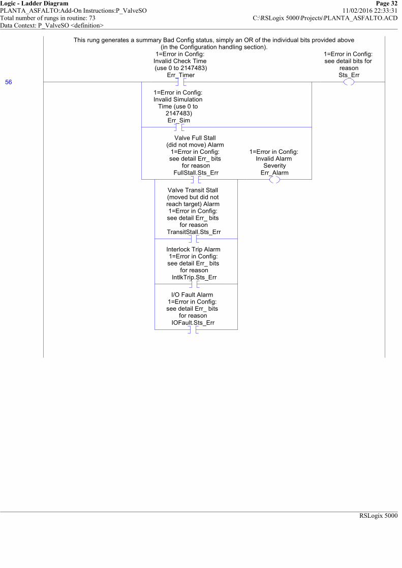
Logic - Ladder Diagram Page 32PLANTA_ASFALTO:Add-On Instructions:P_ValveSO 11/02/2016 22:33:31Total number of rungs in routine: 73 C:\RSLogix 5000\Projects\PLANTA_ASFALTO.ACDData Context: P_ValveSO <definition>
RSLogix 5000
This rung generates a summary Bad Config status, simply an OR of the individual bits provided above(in the Configuration handling section).
56
1=Error in Config: Invalid Check Time (use 0 to 2147483)
Err_Timer
1=Error in Config: Invalid Simulation
Time (use 0 to 2147483)Err_Sim
Valve Full Stall (did not move) Alarm
1=Error in Config: see detail Err_ bits
for reasonFullStall.Sts_Err
Valve Transit Stall (moved but did not reach target) Alarm 1=Error in Config: see detail Err_ bits
for reasonTransitStall.Sts_Err
Interlock Trip Alarm 1=Error in Config: see detail Err_ bits
for reasonIntlkTrip.Sts_Err
I/O Fault Alarm 1=Error in Config: see detail Err_ bits
for reasonIOFault.Sts_Err
1=Error in Config: Invalid Alarm
SeverityErr_Alarm
1=Error in Config: see detail bits for
reasonSts_Err
This rung generates a summary Bad Config status, simply an OR of the individual bits provided above(in the Configuration handling section).

Logic - Ladder Diagram Page 33PLANTA_ASFALTO:Add-On Instructions:P_ValveSO 11/02/2016 22:33:31Total number of rungs in routine: 73 C:\RSLogix 5000\Projects\PLANTA_ASFALTO.ACDData Context: P_ValveSO <definition>
RSLogix 5000
Alarm Status bits are a copy of the internal Alarm AOI Status bits.
57
Valve Full Stall (did not move) Alarm
Alarm output 1=In Alarm
FullStall.Alm
1=Valve Full Stall (failed to move at
all) AlarmAlm_FullStall
Valve Full Stall (did not move) Alarm Alarm acknowledged
status: 1=Ack rcvdFullStall.Ack
1=Full Stall Alarm has been
acknowledgedAck_FullStall
Valve Full Stall (did not move) Alarm
1=Alarm has been Disabled by
Maintanance (will not be sent)
FullStall.Disabled
1=Full Stall Alarm has been disabled
(will not be sent)Sts_FullStallDisabled
Valve Full Stall (did not move) Alarm
1=Alarm has been Inhibited by Program
(will not be sent)FullStall.Inhibited
1=Full Stall Alarm has been inhibited
by logicSts_FullStallInhibited
Valve Full Stall (did not move) Alarm
1=Alarm has been Suppressed by Operator (not visible on HMI)
FullStall.Suppressed
1=Full Stall Alarm has been suppressed
(logged only)Sts_FullStallSuppressed
Alarm Status bits are a copy of the internal Alarm AOI Status bits.
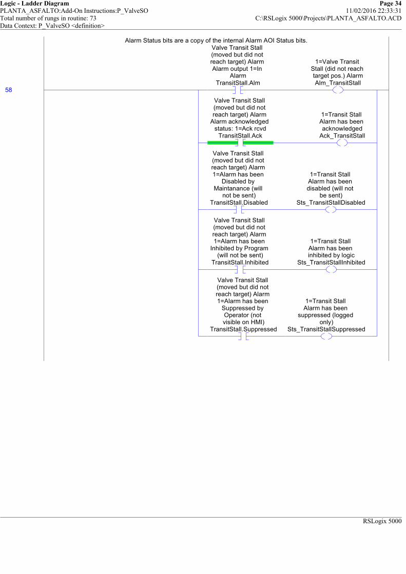
Logic - Ladder Diagram Page 34PLANTA_ASFALTO:Add-On Instructions:P_ValveSO 11/02/2016 22:33:31Total number of rungs in routine: 73 C:\RSLogix 5000\Projects\PLANTA_ASFALTO.ACDData Context: P_ValveSO <definition>
RSLogix 5000
Alarm Status bits are a copy of the internal Alarm AOI Status bits.
58
Valve Transit Stall (moved but did not reach target) Alarm Alarm output 1=In
AlarmTransitStall.Alm
1=Valve Transit Stall (did not reach target pos.) AlarmAlm_TransitStall
Valve Transit Stall (moved but did not reach target) Alarm
Alarm acknowledged status: 1=Ack rcvd
TransitStall.Ack
1=Transit Stall Alarm has been acknowledged
Ack_TransitStall
Valve Transit Stall (moved but did not reach target) Alarm 1=Alarm has been
Disabled by Maintanance (will
not be sent)TransitStall.Disabled
1=Transit Stall Alarm has been disabled (will not
be sent)Sts_TransitStallDisabled
Valve Transit Stall (moved but did not reach target) Alarm 1=Alarm has been
Inhibited by Program (will not be sent)
TransitStall.Inhibited
1=Transit Stall Alarm has been inhibited by logic
Sts_TransitStallInhibited
Valve Transit Stall (moved but did not reach target) Alarm 1=Alarm has been
Suppressed by Operator (not visible on HMI)
TransitStall.Suppressed
1=Transit Stall Alarm has been
suppressed (logged only)
Sts_TransitStallSuppressed
Alarm Status bits are a copy of the internal Alarm AOI Status bits.

Logic - Ladder Diagram Page 35PLANTA_ASFALTO:Add-On Instructions:P_ValveSO 11/02/2016 22:33:31Total number of rungs in routine: 73 C:\RSLogix 5000\Projects\PLANTA_ASFALTO.ACDData Context: P_ValveSO <definition>
RSLogix 5000
Alarm Status bits are a copy of the internal Alarm AOI Status bits.
59
Interlock Trip Alarm Alarm output 1=In
AlarmIntlkTrip.Alm
1=Alarm: Valve de-energized by an Interlock NOT OK
Alm_IntlkTrip
Interlock Trip Alarm Alarm acknowledged
status: 1=Ack rcvdIntlkTrip.Ack
1=Interlock Trip Alarm has been acknowledgedAck_IntlkTrip
Interlock Trip Alarm 1=Alarm has been
Disabled by Maintanance (will
not be sent)IntlkTrip.Disabled
1=Interlock Trip Alarm is Disabled (not saved or sent)
Sts_IntlkTripDisabled
Interlock Trip Alarm 1=Alarm has been
Inhibited by Program (will not be sent)IntlkTrip.Inhibited
1=Interlock Trip Alarm has been inhibited by logic
Sts_IntlkTripInhibited
Interlock Trip Alarm 1=Alarm has been
Suppressed by Operator (not visible on HMI)
IntlkTrip.Suppressed
1=Interlock Trip Alarm has been
suppressed (logged only)
Sts_IntlkTripSuppressed
Alarm Status bits are a copy of the internal Alarm AOI Status bits.

Logic - Ladder Diagram Page 36PLANTA_ASFALTO:Add-On Instructions:P_ValveSO 11/02/2016 22:33:31Total number of rungs in routine: 73 C:\RSLogix 5000\Projects\PLANTA_ASFALTO.ACDData Context: P_ValveSO <definition>
RSLogix 5000
Alarm Status bits are a copy of the internal Alarm AOI Status bits.
60
I/O Fault Alarm Alarm output 1=In
AlarmIOFault.Alm
1=I/O Fault AlarmAlm_IOFault
I/O Fault Alarm Alarm acknowledged
status: 1=Ack rcvdIOFault.Ack
1=I/O Fault Alarm has been
acknowledgedAck_IOFault
I/O Fault Alarm 1=Alarm has been
Disabled by Maintanance (will
not be sent)IOFault.Disabled
1=I/O Fault Alarm is Disabled (not saved
or sent)Sts_IOFaultDisabled
I/O Fault Alarm 1=Alarm has been
Inhibited by Program (will not be sent)IOFault.Inhibited
1=I/O Fault Alarm has been inhibited
by logicSts_IOFaultInhibited
I/O Fault Alarm 1=Alarm has been
Suppressed by Operator (not visible on HMI)
IOFault.Suppressed
1=I/O Fault Alarm has been suppressed
(logged only)Sts_IOFaultSuppressed
Alarm Status bits are a copy of the internal Alarm AOI Status bits.
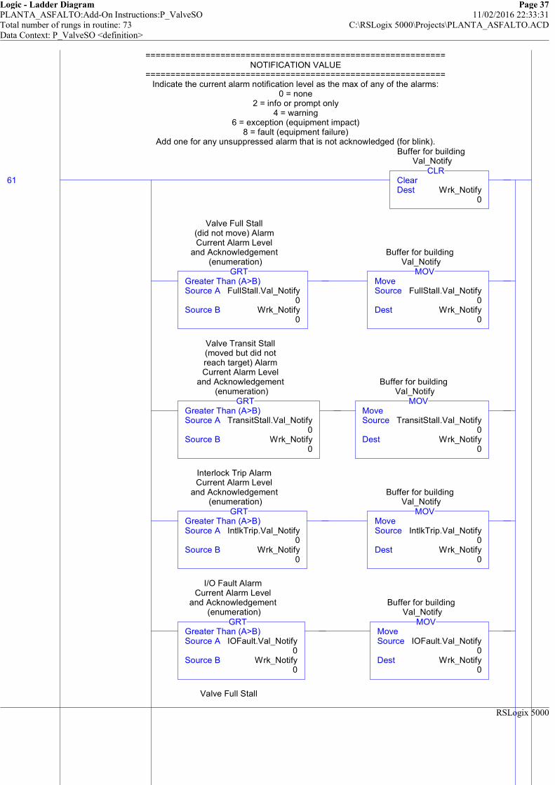
Logic - Ladder Diagram Page 37PLANTA_ASFALTO:Add-On Instructions:P_ValveSO 11/02/2016 22:33:31Total number of rungs in routine: 73 C:\RSLogix 5000\Projects\PLANTA_ASFALTO.ACDData Context: P_ValveSO <definition>
RSLogix 5000
============================================================NOTIFICATION VALUE
============================================================Indicate the current alarm notification level as the max of any of the alarms:
0 = none2 = info or prompt only
4 = warning6 = exception (equipment impact)
8 = fault (equipment failure)Add one for any unsuppressed alarm that is not acknowledged (for blink).
61 ClearDest Wrk_Notify
0
CLR
Buffer for building Val_Notify
Greater Than (A>B)Source A FullStall.Val_Notify
0Source B Wrk_Notify
0
GRT
Valve Full Stall (did not move) Alarm Current Alarm Level
and Acknowledgement (enumeration)
MoveSource FullStall.Val_Notify
0Dest Wrk_Notify
0
MOV
Buffer for building Val_Notify
Greater Than (A>B)Source A TransitStall.Val_Notify
0Source B Wrk_Notify
0
GRT
Valve Transit Stall (moved but did not reach target) Alarm Current Alarm Level
and Acknowledgement (enumeration)
MoveSource TransitStall.Val_Notify
0Dest Wrk_Notify
0
MOV
Buffer for building Val_Notify
Greater Than (A>B)Source A IntlkTrip.Val_Notify
0Source B Wrk_Notify
0
GRT
Interlock Trip Alarm Current Alarm Level
and Acknowledgement (enumeration)
MoveSource IntlkTrip.Val_Notify
0Dest Wrk_Notify
0
MOV
Buffer for building Val_Notify
Greater Than (A>B)Source A IOFault.Val_Notify
0Source B Wrk_Notify
0
GRT
I/O Fault Alarm Current Alarm Level
and Acknowledgement (enumeration)
MoveSource IOFault.Val_Notify
0Dest Wrk_Notify
0
MOV
Buffer for building Val_Notify
Valve Full Stall
============================================================NOTIFICATION VALUE
============================================================Indicate the current alarm notification level as the max of any of the alarms:
0 = none2 = info or prompt only
4 = warning6 = exception (equipment impact)
8 = fault (equipment failure)Add one for any unsuppressed alarm that is not acknowledged (for blink).
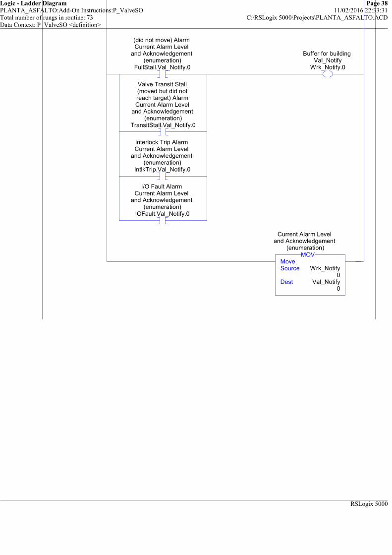
Logic - Ladder Diagram Page 38PLANTA_ASFALTO:Add-On Instructions:P_ValveSO 11/02/2016 22:33:31Total number of rungs in routine: 73 C:\RSLogix 5000\Projects\PLANTA_ASFALTO.ACDData Context: P_ValveSO <definition>
RSLogix 5000
Valve Full Stall (did not move) Alarm Current Alarm Level
and Acknowledgement (enumeration)
FullStall.Val_Notify.0
Valve Transit Stall (moved but did not reach target) Alarm Current Alarm Level
and Acknowledgement (enumeration)
TransitStall.Val_Notify.0
Interlock Trip Alarm Current Alarm Level
and Acknowledgement (enumeration)
IntlkTrip.Val_Notify.0
I/O Fault Alarm Current Alarm Level
and Acknowledgement (enumeration)
IOFault.Val_Notify.0
Buffer for building Val_Notify
Wrk_Notify.0
MoveSource Wrk_Notify
0Dest Val_Notify
0
MOV
Current Alarm Level and Acknowledgement
(enumeration)
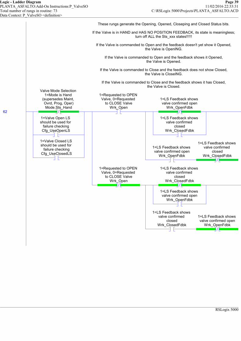
Logic - Ladder Diagram Page 39PLANTA_ASFALTO:Add-On Instructions:P_ValveSO 11/02/2016 22:33:31Total number of rungs in routine: 73 C:\RSLogix 5000\Projects\PLANTA_ASFALTO.ACDData Context: P_ValveSO <definition>
RSLogix 5000
These rungs generate the Opening, Opened, Closeping and Closed Status bits.
If the Valve is in HAND and HAS NO POSITION FEEDBACK, its state is meaningless;turn off ALL the Sts_xxx states!!!!!
If the Valve is commanded to Open and the feedback doesn't yet show it Opened,the Valve is OpenING.
If the Valve is commanded to Open and the feedback shows it Opened,the Valve is Opened.
If the Valve is commanded to Close and the feedback does not show Closed,the Valve is CloseING.
If the Valve is commanded to Close and the feedback shows it has Closed,the Valve is Closed.
62 /
Valve Mode Selection 1=Mode is Hand
(supersedes Maint, Ovrd, Prog, Oper)Mode.Sts_Hand
1=Valve Open LS should be used for
failure checkingCfg_UseOpenLS
1=Valve Closed LS should be used for
failure checkingCfg_UseClosedLS
1=Requested to OPEN Valve, 0=Requested
to CLOSE ValveWrk_Open
/
1=LS Feedback shows valve confirmed open
Wrk_OpenFdbk
1=LS Feedback shows valve confirmed
closedWrk_ClosedFdbk
1=LS Feedback shows valve confirmed open
Wrk_OpenFdbk/
1=LS Feedback shows valve confirmed
closedWrk_ClosedFdbk
/
1=Requested to OPEN Valve, 0=Requested
to CLOSE ValveWrk_Open
/
1=LS Feedback shows valve confirmed
closedWrk_ClosedFdbk
1=LS Feedback shows valve confirmed open
Wrk_OpenFdbk
1=LS Feedback shows valve confirmed
closedWrk_ClosedFdbk
/
1=LS Feedback shows valve confirmed open
Wrk_OpenFdbk
These rungs generate the Opening, Opened, Closeping and Closed Status bits.
If the Valve is in HAND and HAS NO POSITION FEEDBACK, its state is meaningless;turn off ALL the Sts_xxx states!!!!!
If the Valve is commanded to Open and the feedback doesn't yet show it Opened,the Valve is OpenING.
If the Valve is commanded to Open and the feedback shows it Opened,the Valve is Opened.
If the Valve is commanded to Close and the feedback does not show Closed,the Valve is CloseING.
If the Valve is commanded to Close and the feedback shows it has Closed,the Valve is Closed.

Logic - Ladder Diagram Page 40PLANTA_ASFALTO:Add-On Instructions:P_ValveSO 11/02/2016 22:33:31Total number of rungs in routine: 73 C:\RSLogix 5000\Projects\PLANTA_ASFALTO.ACDData Context: P_ValveSO <definition>
RSLogix 5000
1=Valve requested to open and awaiting
open feedbackSts_Opening
1=Valve requested to open and is
confirmed OpenedSts_Opened
1=Valve requested to Close and awaiting
Closed feedbackSts_Closing
1=Valve requested to Close and is
confirmed ClosedSts_Closed

Logic - Ladder Diagram Page 41PLANTA_ASFALTO:Add-On Instructions:P_ValveSO 11/02/2016 22:33:32Total number of rungs in routine: 73 C:\RSLogix 5000\Projects\PLANTA_ASFALTO.ACDData Context: P_ValveSO <definition>
RSLogix 5000
The Valve is AVAILABLE to be opened and closed by automation if in PROGRAM, not disabled, interlocks are OK, permissives are OK (to energize), no FAULTS exist, and I/O comm is
OK (if not in simulation).
63
Valve Mode Selection 1=Mode is Program
Mode.Sts_Prog/
Internal Valve is Disabled
Wrk_Disabled
1=Interlocks OK, valve can energize
Inp_IntlkOK
Internal Bypassable Permissives and
Interlocks are Bypassed flagWrk_Bypass
1=Non-Bypassable Interlocks OK, valve
can energizeInp_NBIntlkOK
1=Permissives OK, Valve can energize
Inp_PermOK
Internal Bypassable Permissives and
Interlocks are Bypassed flagWrk_Bypass
1=Non-Bypassable Permissives OK,
valve can energizeInp_NBPermOK
/
1=Valve requested to open and is
confirmed OpenedSts_Opened
1=Fail Open (energize to close),
0=Fail Closed (energize to open)
Cfg_FailOpen
/
1=Valve requested to Close and is
confirmed ClosedSts_Closed
/
1=Fail Open (energize to close),
0=Fail Closed (energize to open)
Cfg_FailOpen
/
Valve Full Stall (did not move) Alarm
Alarm output 1=In Alarm
FullStall.Alm
/
Valve Transit Stall (moved but did not reach target) Alarm Alarm output 1=In
AlarmTransitStall.Alm
/
Input Communication Status 0=OK, 1=fail
Inp_IOFault
1=Simulate working valve; 0=Open/Close/ Monitor actual valve
Inp_Sim
1=Valve available for control by
automation (Prog)Sts_Available
The Valve is AVAILABLE to be opened and closed by automation if in PROGRAM, not disabled, interlocks are OK, permissives are OK (to energize), no FAULTS exist, and I/O comm is
OK (if not in simulation).
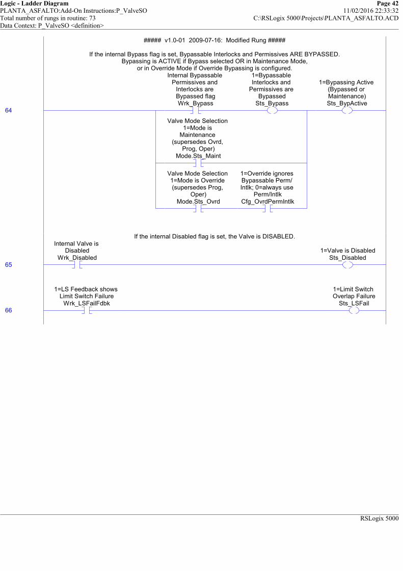
Logic - Ladder Diagram Page 42PLANTA_ASFALTO:Add-On Instructions:P_ValveSO 11/02/2016 22:33:32Total number of rungs in routine: 73 C:\RSLogix 5000\Projects\PLANTA_ASFALTO.ACDData Context: P_ValveSO <definition>
RSLogix 5000
##### v1.0-01 2009-07-16: Modified Rung #####
If the internal Bypass flag is set, Bypassable Interlocks and Permissives ARE BYPASSED.Bypassing is ACTIVE if Bypass selected OR in Maintenance Mode,
or in Override Mode if Override Bypassing is configured.
64
Internal Bypassable Permissives and
Interlocks are Bypassed flagWrk_Bypass
1=Bypassable Interlocks and
Permissives are Bypassed
Sts_Bypass
Valve Mode Selection 1=Mode is
Maintenance (supersedes Ovrd,
Prog, Oper)Mode.Sts_Maint
Valve Mode Selection 1=Mode is Override (supersedes Prog,
Oper)Mode.Sts_Ovrd
1=Override ignores Bypassable Perm/ Intlk; 0=always use
Perm/IntlkCfg_OvrdPermIntlk
1=Bypassing Active (Bypassed or Maintenance)Sts_BypActive
##### v1.0-01 2009-07-16: Modified Rung #####
If the internal Bypass flag is set, Bypassable Interlocks and Permissives ARE BYPASSED.Bypassing is ACTIVE if Bypass selected OR in Maintenance Mode,
or in Override Mode if Override Bypassing is configured.
If the internal Disabled flag is set, the Valve is DISABLED.
65
Internal Valve is Disabled
Wrk_Disabled1=Valve is Disabled
Sts_Disabled
If the internal Disabled flag is set, the Valve is DISABLED.
66
1=LS Feedback shows Limit Switch Failure
Wrk_LSFailFdbk
1=Limit Switch Overlap Failure
Sts_LSFail
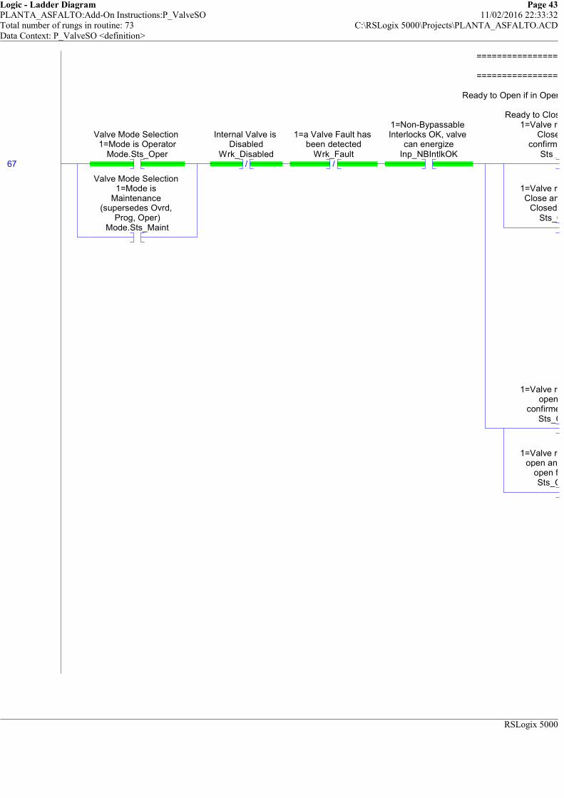
Logic - Ladder Diagram Page 43PLANTA_ASFALTO:Add-On Instructions:P_ValveSO 11/02/2016 22:33:32Total number of rungs in routine: 73 C:\RSLogix 5000\Projects\PLANTA_ASFALTO.ACDData Context: P_ValveSO <definition>
RSLogix 5000
============================================================
============================================================
Ready to Open if in Operator Manual, Closed, and Permissives and Interlocks are OK.
Ready to Close if in Operator Manual and (Opened or Opening).
67
Valve Mode Selection 1=Mode is Operator
Mode.Sts_Oper
Valve Mode Selection 1=Mode is
Maintenance (supersedes Ovrd,
Prog, Oper)Mode.Sts_Maint
/
Internal Valve is Disabled
Wrk_Disabled/
1=a Valve Fault has been detected
Wrk_Fault
1=Non-Bypassable Interlocks OK, valve
can energizeInp_NBIntlkOK
1=Valve requested to Close and is
confirmed ClosedSts_Closed
1=Valve requested to Close and awaiting
Closed feedbackSts_Closing
1=Valve requested to open and is
confirmed OpenedSts_Opened
1=Valve requested to open and awaiting
open feedbackSts_Opening
============================================================
============================================================
Ready to Open if in Operator Manual, Closed, and Permissives and Interlocks are OK.
Ready to Close if in Operator Manual and (Opened or Opening).
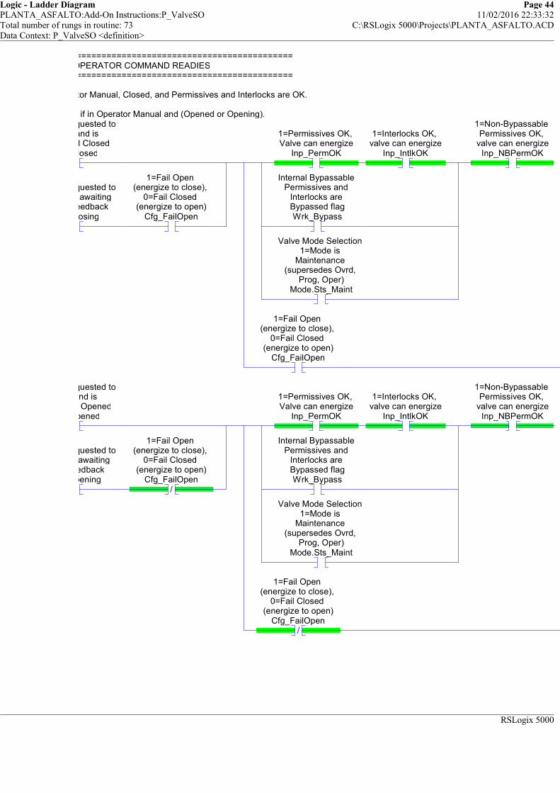
Logic - Ladder Diagram Page 44PLANTA_ASFALTO:Add-On Instructions:P_ValveSO 11/02/2016 22:33:32Total number of rungs in routine: 73 C:\RSLogix 5000\Projects\PLANTA_ASFALTO.ACDData Context: P_ValveSO <definition>
RSLogix 5000
============================================================OPERATOR COMMAND READIES
============================================================
Ready to Open if in Operator Manual, Closed, and Permissives and Interlocks are OK.
Ready to Close if in Operator Manual and (Opened or Opening).1=Valve requested to
Close and is confirmed Closed
Sts_Closed
1=Valve requested to Close and awaiting
Closed feedbackSts_Closing
1=Fail Open (energize to close),
0=Fail Closed (energize to open)
Cfg_FailOpen
1=Permissives OK, Valve can energize
Inp_PermOK
1=Interlocks OK, valve can energize
Inp_IntlkOK
Internal Bypassable Permissives and
Interlocks are Bypassed flagWrk_Bypass
Valve Mode Selection 1=Mode is
Maintenance (supersedes Ovrd,
Prog, Oper)Mode.Sts_Maint
1=Non-Bypassable Permissives OK,
valve can energizeInp_NBPermOK
1=Fail Open (energize to close),
0=Fail Closed (energize to open)
Cfg_FailOpen
1=Valve requested to open and is
confirmed OpenedSts_Opened
1=Valve requested to open and awaiting
open feedbackSts_Opening
/
1=Fail Open (energize to close),
0=Fail Closed (energize to open)
Cfg_FailOpen
1=Permissives OK, Valve can energize
Inp_PermOK
1=Interlocks OK, valve can energize
Inp_IntlkOK
Internal Bypassable Permissives and
Interlocks are Bypassed flagWrk_Bypass
Valve Mode Selection 1=Mode is
Maintenance (supersedes Ovrd,
Prog, Oper)Mode.Sts_Maint
1=Non-Bypassable Permissives OK,
valve can energizeInp_NBPermOK
/
1=Fail Open (energize to close),
0=Fail Closed (energize to open)
Cfg_FailOpen
============================================================OPERATOR COMMAND READIES
============================================================
Ready to Open if in Operator Manual, Closed, and Permissives and Interlocks are OK.
Ready to Close if in Operator Manual and (Opened or Opening).

Logic - Ladder Diagram Page 45PLANTA_ASFALTO:Add-On Instructions:P_ValveSO 11/02/2016 22:33:32Total number of rungs in routine: 73 C:\RSLogix 5000\Projects\PLANTA_ASFALTO.ACDData Context: P_ValveSO <definition>
RSLogix 5000
1=Ready to receive OCmd_Open (enables
HMI button)Rdy_Open
1=Ready to receive OCmd_Close (enables
HMI button)Rdy_Close
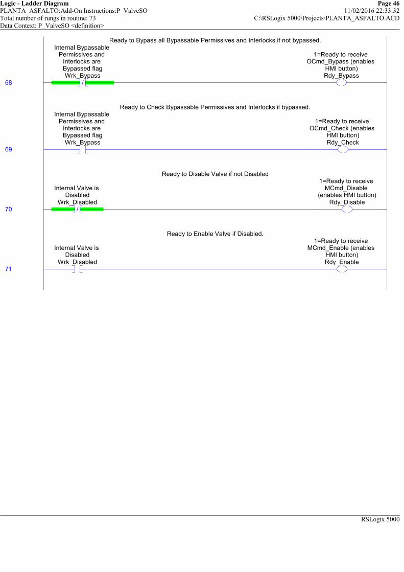
Logic - Ladder Diagram Page 46PLANTA_ASFALTO:Add-On Instructions:P_ValveSO 11/02/2016 22:33:32Total number of rungs in routine: 73 C:\RSLogix 5000\Projects\PLANTA_ASFALTO.ACDData Context: P_ValveSO <definition>
RSLogix 5000
Ready to Bypass all Bypassable Permissives and Interlocks if not bypassed.
68 /
Internal Bypassable Permissives and
Interlocks are Bypassed flagWrk_Bypass
1=Ready to receive OCmd_Bypass (enables
HMI button)Rdy_Bypass
Ready to Bypass all Bypassable Permissives and Interlocks if not bypassed.
Ready to Check Bypassable Permissives and Interlocks if bypassed.
69
Internal Bypassable Permissives and
Interlocks are Bypassed flagWrk_Bypass
1=Ready to receive OCmd_Check (enables
HMI button)Rdy_Check
Ready to Check Bypassable Permissives and Interlocks if bypassed.
Ready to Disable Valve if not Disabled
70 /
Internal Valve is Disabled
Wrk_Disabled
1=Ready to receive MCmd_Disable
(enables HMI button)Rdy_Disable
Ready to Disable Valve if not Disabled
Ready to Enable Valve if Disabled.
71
Internal Valve is Disabled
Wrk_Disabled
1=Ready to receive MCmd_Enable (enables
HMI button)Rdy_Enable
Ready to Enable Valve if Disabled.

Logic - Ladder Diagram Page 47PLANTA_ASFALTO:Add-On Instructions:P_ValveSO 11/02/2016 22:33:32Total number of rungs in routine: 73 C:\RSLogix 5000\Projects\PLANTA_ASFALTO.ACDData Context: P_ValveSO <definition>
RSLogix 5000
This object requires a Reset if any of its Alarms requires a Reset.
72
Valve Full Stall (did not move) Alarm
Ready to receive OCmd_Reset (enable
button)FullStall.Rdy_Reset
Valve Transit Stall (moved but did not reach target) Alarm Ready to receive
OCmd_Reset (enable button)
TransitStall.Rdy_Reset
Interlock Trip Alarm Ready to receive
OCmd_Reset (enable button)
IntlkTrip.Rdy_Reset
I/O Fault Alarm Ready to receive
OCmd_Reset (enable button)
IOFault.Rdy_Reset
1=Ready to receive OCmd_Reset (enables
HMI button)Rdy_Reset
This object requires a Reset if any of its Alarms requires a Reset.
(End)