
8/10/2019 A 5 11kV 1.2, 2.4 &3 MVAr Cap SpecInfra 240709
http://slidepdf.com/reader/full/a-5-11kv-12-24-3-mvar-cap-specinfra-240709 1/57
TECHNICAL SPECIFICATION FOR 11 kV, 1.2/2.4/3.0 MVAR CAPACITOR BANKWITH DOUBLE STAR ARRANGEMENT & ASSOCIATED EQUIPMENTS
SEAL & SIGNATURE OF THE TENDERER
Page 1 of 57
Maharashtra State Electricity Distribution Co.
Ltd.
SPECIFICATION NO. MSEDCL/ DIST: MM-III/08/2007/R-2
TECHNICAL SPECIFICATIONFOR
11 KV1.2/2.4/3.0 MVAR CAPACITOR BANK
WITH DOUBLE STAR ARRANGEMENT
AND ASSOCIATED EQUIPMEMTS
IN
33KV SUB-STATIONS
SE(MSC) CE(DIST.) DIRECTOR (OPERATIONS)
8/10/2019 A 5 11kV 1.2, 2.4 &3 MVAr Cap SpecInfra 240709
http://slidepdf.com/reader/full/a-5-11kv-12-24-3-mvar-cap-specinfra-240709 2/57
TECHNICAL SPECIFICATION FOR 11 kV, 1.2/2.4/3.0 MVAR CAPACITOR BANKWITH DOUBLE STAR ARRANGEMENT & ASSOCIATED EQUIPMENTS
SEAL & SIGNATURE OF THE TENDERER
Page 2 of 57
TECHNICAL SPECIFICATION FOR 1.2/2.4/3.0 MVAR CAPACITOR BANK WITH
DOUBLE STAR ARRANGEMENT AND ASSOCIATED EQUIPMENTS
IN 33KV SUB-STATIONS
SPECIFICATION NO.MM-III/ 08/2007/R-2
INDEX
Sr.No Particulars Page No
1. Scope 3-4
2. Service Conditions 4-5
3. Operating Conditions 5
4. Standards 5
5. Principle Technical Parameters 5
6. General Technical Requirements 5-8
7. Capacitor Bank 8-12
8. 11kV Circuit Breaker 12-14
9. 11kV Current Transformers 14-17
10. Neutral Current Transformer 17
11. Support Structures 17-19
12. Series Reactor 19-20
13. Lightening Arrestors 20-21
14. Isolators 21-24
15. Control & Protection Equipments 24-28
16. Tests 29
17. Documentation 29-31
18. Errection & commissioning 31
19. Earthing System 32-3420. Control Cables 34-35
21. Fitting & accessories 35
22. Annexure-I 36
23. Annexure-II- A 37-38
24. Annexure-II- B 39- 40
25. Annexure-II- C 41
26. Annexure-II- D 42
27. Annexure-II- E 43
28. Annexure-II- F 44
29. Annexure-II- G 45-46
30. Annexure-II- H 47-4831. Annexure-III 49-50
32. Schedule – L 51
33. Schedule – F 52
34. Drawings 53-57

8/10/2019 A 5 11kV 1.2, 2.4 &3 MVAr Cap SpecInfra 240709
http://slidepdf.com/reader/full/a-5-11kv-12-24-3-mvar-cap-specinfra-240709 3/57
TECHNICAL SPECIFICATION FOR 11 kV, 1.2/2.4/3.0 MVAR CAPACITOR BANKWITH DOUBLE STAR ARRANGEMENT & ASSOCIATED EQUIPMENTS
SEAL & SIGNATURE OF THE TENDERER
Page 3 of 57
SPECIFICATION FOR 11 kV, 1.2/2.4/3.0 MVAR CAPACITOR BANK WITHDOUBLE STAR ARRANGEMENT & ASSOCIATED EQUIPMENTS
1.0 SCOPE:
1.1 This specification covers design & supply of 1.2/2.4 /3.0 MVArcapacitor bank along with all required equipments to be installed in
33kV sub stations. The capacitor bank shall consist of capacitor bank,circuit breaker, Series Reactor, control & relay panel, isolators, LAs,CTs and NCT, conductor, all type of necessary connectors along withsuitable mounting structure. All these equipment shall have suitableterminal/equipment connectors as detailed under clause No.11.2 of the
specification.
1.2 The equipments to be supplied against this specification are required
for vital installations where continuity of service is very important. Thedesign, materials and manufacture of the equipment shall, therefore,be of the highest order to ensure continuous and trouble-free serviceover the years.
1.3 The equipment offered shall be complete with all parts necessary fortheir effective and trouble-free operation. Such parts will be deemed to
be within the scope of the supply irrespective of whether they arespecifically indicated in the commercial order or not.
1.4 Configuration: The major equipments involved for each mechanicallyswitched shunt capacitor bank are as follows.
Sr.No.
Particulars Qty.Reqd.
1. 11 kV ,1.2/2.4 /3.0 MVAr capacitor bank 1Set.
2. 11 kV Circuit Breaker 1No.
3. 11 kV Isolator with earth blade 1No.
4. 11 kV lighting Arrestors 3No.
5. 11 kV Current Transformer 3No.
6. 11 kV Neutral current transformer 1No.
7. 11 kV Single phase Current Limiting Reactors 6No.
8. Control & Protection Equipment. 1Set.
It is not the intent to specify herein complete details of design and
construction. The equipment offered shall conform to the relevantstandards and be of high quality, sturdy, robust and of good design and
workmanship complete in all respects and capable to performcontinuous and satisfactory operations in the actual service conditionsat site and shall have sufficiently long life in service as per statutoryrequirements. The dimensional drawings attached with this
8/10/2019 A 5 11kV 1.2, 2.4 &3 MVAr Cap SpecInfra 240709
http://slidepdf.com/reader/full/a-5-11kv-12-24-3-mvar-cap-specinfra-240709 4/57
TECHNICAL SPECIFICATION FOR 11 kV, 1.2/2.4/3.0 MVAR CAPACITOR BANKWITH DOUBLE STAR ARRANGEMENT & ASSOCIATED EQUIPMENTS
SEAL & SIGNATURE OF THE TENDERER
Page 4 of 57
specification and the notes thereto are generally of illustrative nature.
In actual practice, not withstanding any anomalies, discrepancies,omissions, in-completeness, etc. in these specifications and attacheddrawings, the design and constructional aspects, including materialsand dimensions, will be subject to good engineering practice in
conformity with the required quality of the product, and to suchtolerances, allowances and requirements for clearances etc. as arenecessary by virtue of various stipulations in that respect in the
relevant Indian Standards, IEC standards, I.E. Rules, I.E. Act and otherstatutory provisions.
1.6 The Tenderer/supplier shall bind himself to abide by theseconsiderations to the entire satisfaction of the purchaser and will berequired to adjust such details at no extra cost to the purchaser overand above the tendered rates and prices.
1.7 The tenderer shall furnish in his offer a list of recommended spares
with unit rates for each set of equipment that may be necessary forsatisfactory operation and maintenance of circuit breaker and Isolatorsfor a period of 5 years. The purchaser reserves right of selection ofitems and quantities of these spares to be ordered. The cost of suchspares shall not be considered for tender evaluation.
1.8 The tenderer shall submit a list and unit rates of all the special tools,equipment and instruments required for erection, testing,commissioning and maintenance of the equipment. The purchaser shall
decide the quantity of tools to be ordered. Prices of these tools shall notbe considered for tender evaluation. However, the list of necessary
tools/equipment which will be supplied free of cost with each CB maybe furnished separately.
The equipment/material offered shall be entirely satisfactory foroperation under the conditions indicated below:-
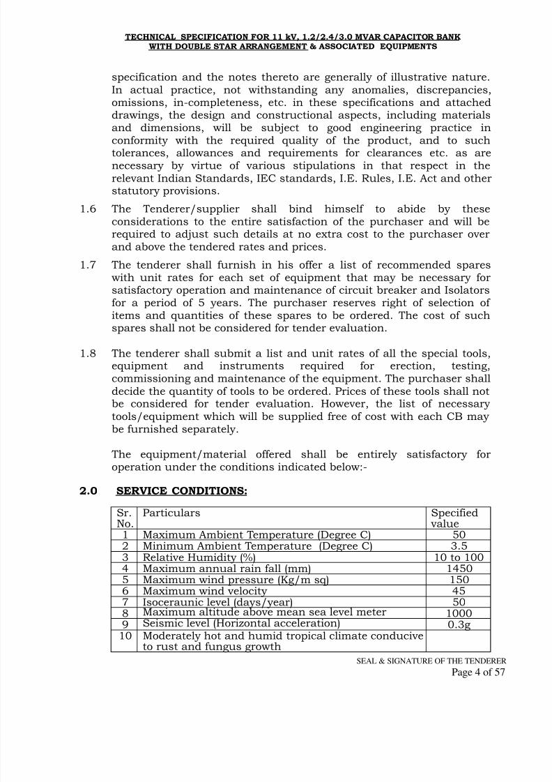
2.0 SERVICE CONDITIONS:
Sr.No.
Particulars Specifiedvalue
1 Maximum Ambient Temperature (Degree C) 50
2 Minimum Ambient Temperature (Degree C) 3.53 Relative Humidity (%) 10 to 1004 Maximum annual rain fall (mm) 14505 Maximum wind pressure (Kg/m sq) 1506 Maximum wind velocity 457 Isoceraunic level (days/year) 508 Maximum altitude above mean sea level meter 10009 Seismic level (Horizontal acceleration) 0.3g10 Moderately hot and humid tropical climate conducive
to rust and fungus growth
8/10/2019 A 5 11kV 1.2, 2.4 &3 MVAr Cap SpecInfra 240709
http://slidepdf.com/reader/full/a-5-11kv-12-24-3-mvar-cap-specinfra-240709 5/57
TECHNICAL SPECIFICATION FOR 11 kV, 1.2/2.4/3.0 MVAR CAPACITOR BANKWITH DOUBLE STAR ARRANGEMENT & ASSOCIATED EQUIPMENTS
SEAL & SIGNATURE OF THE TENDERER
Page 5 of 57
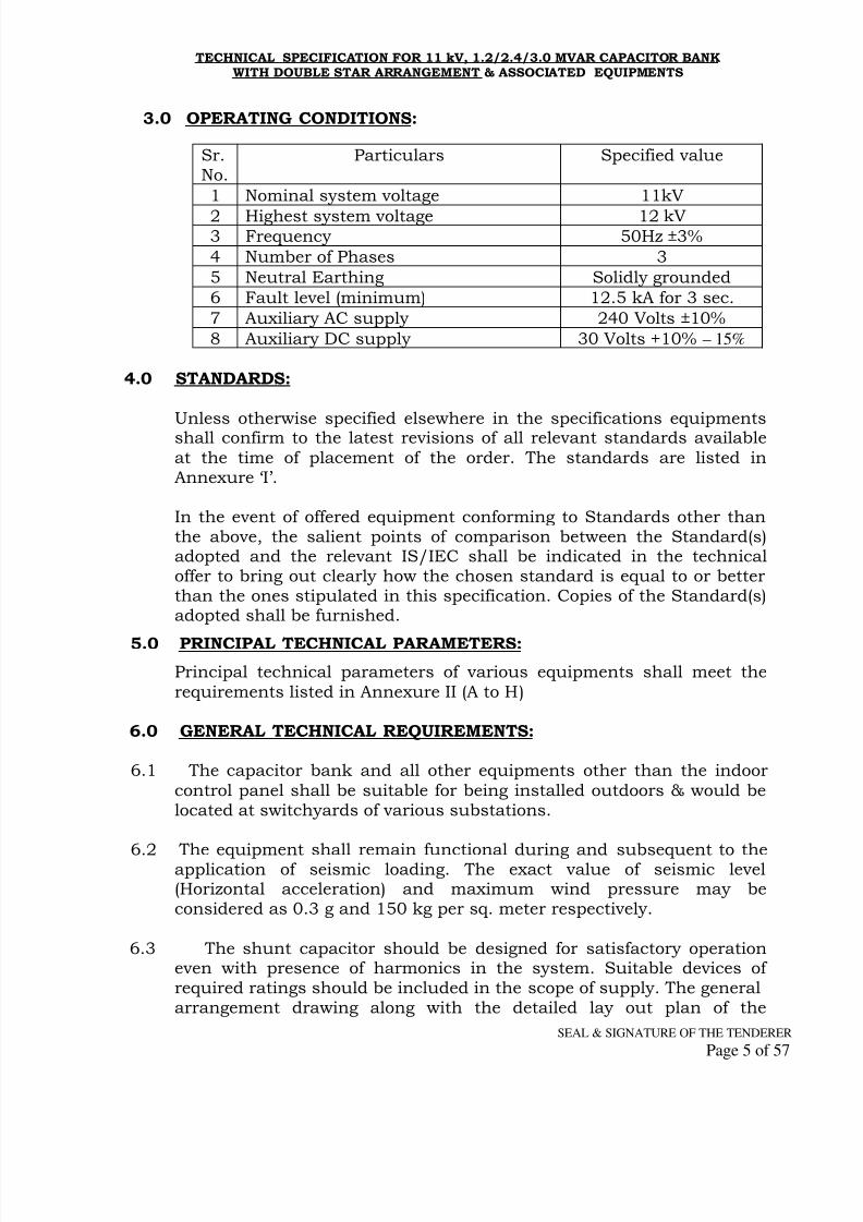
3.0 OPERATING CONDITIONS:
Sr.No.
Particulars Specified value
1 Nominal system voltage 11kV
2 Highest system voltage 12 kV3 Frequency 50Hz ±3% 4 Number of Phases 3 5 Neutral Earthing Solidly grounded 6 Fault level (minimum) 12.5 kA for 3 sec. 7 Auxiliary AC supply 240 Volts ±10% 8 Auxiliary DC supply 30 Volts +10% – 15%
4.0 STANDARDS:
Unless otherwise specified elsewhere in the specifications equipmentsshall confirm to the latest revisions of all relevant standards available
at the time of placement of the order. The standards are listed inAnnexure ‘I’.
In the event of offered equipment conforming to Standards other thanthe above, the salient points of comparison between the Standard(s)adopted and the relevant IS/IEC shall be indicated in the technicaloffer to bring out clearly how the chosen standard is equal to or betterthan the ones stipulated in this specification. Copies of the Standard(s)adopted shall be furnished.
5.0 PRINCIPAL TECHNICAL PARAMETERS:
Principal technical parameters of various equipments shall meet the
requirements listed in Annexure II (A to H)
6.0 GENERAL TECHNICAL REQUIREMENTS:
6.1 The capacitor bank and all other equipments other than the indoor
control panel shall be suitable for being installed outdoors & would belocated at switchyards of various substations.
6.2 The equipment shall remain functional during and subsequent to theapplication of seismic loading. The exact value of seismic level(Horizontal acceleration) and maximum wind pressure may beconsidered as 0.3 g and 150 kg per sq. meter respectively.
6.3 The shunt capacitor should be designed for satisfactory operationeven with presence of harmonics in the system. Suitable devices ofrequired ratings should be included in the scope of supply. The generalarrangement drawing along with the detailed lay out plan of the

8/10/2019 A 5 11kV 1.2, 2.4 &3 MVAr Cap SpecInfra 240709
http://slidepdf.com/reader/full/a-5-11kv-12-24-3-mvar-cap-specinfra-240709 6/57
TECHNICAL SPECIFICATION FOR 11 kV, 1.2/2.4/3.0 MVAR CAPACITOR BANKWITH DOUBLE STAR ARRANGEMENT & ASSOCIATED EQUIPMENTS
SEAL & SIGNATURE OF THE TENDERER
Page 6 of 57
capacitor bank shall be submitted for necessary approval.
6.4 Each bank shall be of 1.2/2.4/3.0 MVAr rating at 11kV and shall bedouble star connected bank with neutral point connected through NCT.If there are more than one capacitor banks in the sub-station, damping
reactors of 0.2% rating should be used on the neutral side of thecapacitor bank. The inductance value will control amplitude andfrequency of the inrush current at back to back switching. Peak
capacitor inrush current shall be less than 100 times rated current ofthe capacitor and less than the breaker making current.
6.5 The protective scheme shall be by a current relay arranged as follows:
i) If the failure of one or more elements cause an over voltage ofless than 10% tolerable on the other remaining healthy units,
then the unbalance current shall cause in the first step tosound an alarm. But if more than the above numbers ofelements fail causing the voltage rise of more than 10% on the
other healthy units or the over voltage on the remaininghealthy elements exceeds 65% then the unbalance current
shall cause to trip and isolate the capacitor bankinstantaneously in the second step.
ii) The per phase and individual star group rating shall be builtup if required by series- parallel combination of individualunits so as to achieve the desired bank rating.
iii) Internal fuses shall comply with IS- 12672 and shall beprovided for the several individual elements within each unit.
iv) Although the tolerances in the output rating of each individualunit shall be as per clause 13.1 of IS- 13925 (Part I ) 1998, yetit shall be ensured that in a completely assembled bank, thedepartures from the nominal rating and with in the specified
tolerance values shall not cause nuisance alarm or trippingsince such alarm or tripping shall be to meet only with theprotective requirements specified in (iii).
v) Individual units shall be designed to meet the requirements of
the permissible overloads & with internal discharge devices asspecified in IS- 13925 (Part I)/ 1998.
vi) Internal fuses for individual elements within unit shall be asper the manufacturer’s design and shall be ensured for
adequacy such as to withstand normal switching inrushtransient currents, discharge current when the bank is
8/10/2019 A 5 11kV 1.2, 2.4 &3 MVAr Cap SpecInfra 240709
http://slidepdf.com/reader/full/a-5-11kv-12-24-3-mvar-cap-specinfra-240709 7/57
TECHNICAL SPECIFICATION FOR 11 kV, 1.2/2.4/3.0 MVAR CAPACITOR BANKWITH DOUBLE STAR ARRANGEMENT & ASSOCIATED EQUIPMENTS
SEAL & SIGNATURE OF THE TENDERER
Page 7 of 57
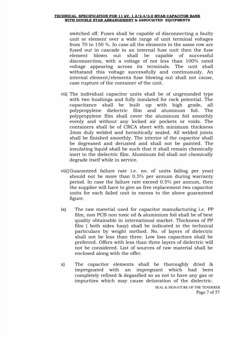
switched off. Fuses shall be capable of disconnecting a faulty
unit or element over a wide range of unit terminal voltagesfrom 70 to 150 %. In case all the elements in the same row arefused out in cascade in an internal fuse unit then the fuseelement blown out shall be capable of successful
disconnection, with a voltage of not less than 100% ratedvoltage appearing across its terminals. The unit shallwithstand this voltage successfully and continuously. An
internal element/elements fuse blowing out shall not cause,case rupture of the container of the unit.
vii) The individual capacitor units shall be of ungrounded typewith two bushings and fully insulated for rack potential. Thecapacitance shall be built up with high grade, allpolypropylene dielectric film and aluminum foil. The
polypropylene film shall cover the aluminum foil smoothlyevenly and without any locked air pockets or voids. Thecontainers shall be of CRCA sheet with minimum thickness
2mm duly welded and hermitically sealed. All welded jointsshall be finished smoothly. The interior of the capacitor shall
be degreased and derusted and shall not be painted. Theinsulating liquid shall be such that it shall remain chemicallyinert to the dielectric film. Aluminum foil shall not chemicallydegrade itself while in service.
viii] Guaranteed failure rate i.e. no. of units failing per year)
should not be more than 0.5% per annum during warrantyperiod. In case the failure rate exceed 0.5% per annum, thenthe supplier will have to give as free replacement two capacitorunits for each failed unit in excess to the above guaranteedfigure.
ix) The raw material used for capacitor manufacturing i.e. PPfilm, non PCB non toxic oil & aluminium foil shall be of best
quality obtainable in international market. Thickness of PPfilm ( both sides hazy) shall be indicated in the technicalparticulars by weight method. No. of layers of dielectric
shall not be less than three. Low loss capacitors shall bepreferred. Offers with less than three layers of dielectric will
not be considered. List of sources of raw material shall beenclosed along with the offer.
x) The capacitor elements shall be thoroughly dried &impregnated with an impregnant which had been
completely refined & degasified so as not to have any gas orimpurities which may cause detioration of the dielectric.

8/10/2019 A 5 11kV 1.2, 2.4 &3 MVAr Cap SpecInfra 240709
http://slidepdf.com/reader/full/a-5-11kv-12-24-3-mvar-cap-specinfra-240709 8/57
TECHNICAL SPECIFICATION FOR 11 kV, 1.2/2.4/3.0 MVAR CAPACITOR BANKWITH DOUBLE STAR ARRANGEMENT & ASSOCIATED EQUIPMENTS
SEAL & SIGNATURE OF THE TENDERER
Page 8 of 57
The impregnant used shall have low viscosity & high
chemical stability. The impregnant should be non-PCB(NPCB)
6.6 Clearances and spacing as indicated below shall be provided.
a) Phase to phase (Electrical) clearance for Breaker poles(minimum)
280 mm
b) Phase to phase (Electrical) clearance for C.T.s & P.T.s(minimum)
370 mm
c) Phase to earth clearance (H.T. Terminal to nearestgrounded metal part)
370 mm
d) Height of 11 kV terminals from ground level (min) 3100 mm
e) Spacing between isolator poles (Centre to Centre) (fixed) 1000 mm
f) Height of lowest part of support insulator from groundlevel (minimum)
2800 mm
Tenderers shall confirm in their technical offer that all clearances andspacing as stated above will invariably be provided. Offers without such
confirmation are liable to be rejected.
7.0 CAPACITOR BANK:
7.1 The capacitors shall be arranged in double star. Neutral Currenttransformer provided shall detect any unbalance due to Capacitor unitfailure. Neutral Current transformer shall be provided between two Starpoints of the bank. Star point shall be ungrounded.
Capacitor unit should be made up of all polypropylene filmdielectric with NON PCB impregnant liquid and provide with internal
fuse element. The containers shall be made from CRCA sheet ofthickness not less than 2mm.(14 SWG). The Capacitor unit should bearranged in open galvanized steel rack with copper tinned conductorsfor their interconnections and aluminium bus bar for interconnectionsbetween capacitor bank, L.A., series reactor and neutral currenttransformer.
7.2 The container shall be hermetically sealed by controlled arc welding/tigwelding process. The metal flanges of the bushing should be soldered/welded to the container and covered with epoxy compound providinga strong hermetical seal to the container. Suitable m ounting brackets,as required by the purchaser shall be welded to the container. Theminimum creepage distance of the bushing shall be 375mm. The

8/10/2019 A 5 11kV 1.2, 2.4 &3 MVAr Cap SpecInfra 240709
http://slidepdf.com/reader/full/a-5-11kv-12-24-3-mvar-cap-specinfra-240709 9/57
TECHNICAL SPECIFICATION FOR 11 kV, 1.2/2.4/3.0 MVAR CAPACITOR BANKWITH DOUBLE STAR ARRANGEMENT & ASSOCIATED EQUIPMENTS
SEAL & SIGNATURE OF THE TENDERER
Page 9 of 57
container of each capacitor unit shall be provided with suitable
earthing terminal clearly marked
7.3 The capacitor bank shall be designed, manufactured and tested as PerIS-13925 (Part-I) 1998. The shunt Capacitor bank would be out door
type & would be Located at switchyards of various substations. Unlessotherwise specified, the capacitors shall be suitable for upper limit of
temperature category 50° C as per IS-13925.
7.4 The standard rated output of a switched capacitor bank shall be1.2/2.4/ 3.0 Mvar as specified at 11.00 kV rated voltage. The bankshall comprise of single phase units of 242 KVAr each rated for 7.3kV
phase to earth voltage connected in double star with neutralsinterconnected through NCT. The maximum permissible overloads with
regard to voltage, current and reactive output shall conform to IS:13925 (part I) 1998 with latest amendments.
7.5 The power loss in capacitors shall not exceed 0.2 Watt/kVAr. Suitabledischarge device shall be connected across the capacitor units inaccordance with the provision of IS: 13925 (part I) 1998 with latestamendments. The discharge device shall reduce the residual voltage
from the cross value of the rated voltage to 50V or less within 10minutes after the capacitor is disconnected from the source ofsupply.
7.6 Better configuration with appropriate capacity of cell units may also be
acceptable subject to approval of the Chief Engineer (Dist.) prior totender finalization.
7.7 The outside of the container should have smooth and tidy look andshould be coated with weather-proof and corrosion-resistant paint of
white or light gray shade. The container/enclosure shall be paintedwith light gray colour, shade 631 as per IS: 5.
7.8 The capacitor shall be provided with a rating plate and terminalmarkings as stipulated in IS: 13925.
7.9 Other details of capacitor bank shall be as per Annexure II ‘A’ ofGuaranteed Technical Parameters attached.
7.10 Mounting structure :
7.10.1 The mounting racks shall be fabricated from suitable steelsections and shall be duly hot dip galvanized as per applicable IS.Mounting racks along with support insulators shall be suitable for
mounting on elevating structure.

8/10/2019 A 5 11kV 1.2, 2.4 &3 MVAr Cap SpecInfra 240709
http://slidepdf.com/reader/full/a-5-11kv-12-24-3-mvar-cap-specinfra-240709 10/57
TECHNICAL SPECIFICATION FOR 11 kV, 1.2/2.4/3.0 MVAR CAPACITOR BANKWITH DOUBLE STAR ARRANGEMENT & ASSOCIATED EQUIPMENTS
SEAL & SIGNATURE OF THE TENDERER
Page 10 of 57
7.10.2 The racks shall be complete with insulators, bolts & nuts,foundation bolts and other hardware, etc. for assembly into completebank. Interconnecting materials and suitable bimetallic terminalconnectors for connection with other equipments shall also be
provided.
7.10.3 The height of the racks of capacitor bank shall be such that for
making electrical connection with the other equipments, properelectrical clearance is maintained.
7.10.4 The hot dip galvanized elevating structure shall be provided ofcapacitor bank & isolator. Provision for mounting of LA, SR & NCTshall be made on the capacitor bank elevating & mounting structure.
7.11 Protection:
7.11.1 Fuses:
i. The fuses shall withstand repeated application of transient
conditions associated with normal duty of capacitor unit.ii. Fuses shall be capable of limiting arc energy within the case of
faulty capacitor to such small proportions that the danger of caserupture is eliminated.
iii. It shall have adequate rupturing capacity for the fault levels atthe terminals of the capacitor.
iv. It shall have adequate thermal capacity to cater for increasedheating which may occur due to harmonics.v. It shall have an ampere rating which will provide proper
co-ordination between its total clearing time current curve andcapacitor unit’s case rupturing capacity.
7.11.2 The capacitor banks shall be provided with the following othersprotections :
(a) Over current and earth fault protection to cover bus faultsbetween the capacitor banks and its controlling circuitbreaker.
(b) Over voltage protection.(c) Unbalance protection.
(d) No volt protection.(e) Leading Power factor Protection.
Requirement of each of the above protection are described below:-

8/10/2019 A 5 11kV 1.2, 2.4 &3 MVAr Cap SpecInfra 240709
http://slidepdf.com/reader/full/a-5-11kv-12-24-3-mvar-cap-specinfra-240709 11/57
TECHNICAL SPECIFICATION FOR 11 kV, 1.2/2.4/3.0 MVAR CAPACITOR BANKWITH DOUBLE STAR ARRANGEMENT & ASSOCIATED EQUIPMENTS
SEAL & SIGNATURE OF THE TENDERER
Page 11 of 57
a) Over-current & Earth fault protection :
Combination of two IDMT relays having 50-200% settings and one EIFrelay of IDMT characteristic with 20-80% setting shall be used withsuitable current transformer.
b) Over-voltage Protection :
Over-voltage shall have an inverse time characteristics and shall beenergized through VT connected to the main bus bars on the source
side of the circuit breaker controlling the capacitor banks. Relay shallhave variable settings from 100% to 130% in steps of at least 1% to 2%.
c) Unbalance Protection :
Unbalance protection shall be provided with current operated relay withseparate one no. NCT for each group of 5 MVAR.
The relays used shall be provided with a time delay device to preventoperation under transients and to allow individual fuses to isolate the
faulty units. Inverse time delay relay may be used.
d) No volt Protection :
Under voltage protection shall be provided to disconnect the bankunder low voltage conditions. A time delay relay must be provided with
adjustable setting of 0 to 10 minutes to provide a time lag before whichthe bank shall not be again switched on (to avoid closing of the circuitbreaker on a trapped charge).
7.11.3 The under-voltage protection shall not operate in the event of faulton 11 KV lines which may dip the bus bar voltage to 50%. There shouldbe provision for adjustments in settings of voltage and time tocoordinate the 11 KV line protections with the under-voltage protection
to avoid malfunctioning of under-voltage relay under line faultconditions.
7.11.4 The power factor meter should be provided.
7.12 Associated Equipments :
The associated equipments as mentioned in clause 1.4 above of this Tech. Specification having detailed specification described hereinaftershall be supplied along with the capacitor banks. The hot dip
galvanized elevating structure shall be provided of capacitor bank &
8/10/2019 A 5 11kV 1.2, 2.4 &3 MVAr Cap SpecInfra 240709
http://slidepdf.com/reader/full/a-5-11kv-12-24-3-mvar-cap-specinfra-240709 12/57
TECHNICAL SPECIFICATION FOR 11 kV, 1.2/2.4/3.0 MVAR CAPACITOR BANKWITH DOUBLE STAR ARRANGEMENT & ASSOCIATED EQUIPMENTS
SEAL & SIGNATURE OF THE TENDERER
Page 12 of 57
isolator. The general arrangement of equipments is shown in the single
line diagram appended with this specification.
8.0 11KV VACUUM CIRCUIT BREAKER:
Technical specifications of Circuit Breaker used for switching on & off ofthe Capacitor bank shall be as follows.
The 11KV circuit breakers offered shall be three phase, out door type,3-pole gang operated, Vacuum circuit breakers having 800 Amps
continuous current rating & short circuit rating of 25 KA for 3 sec.Circuit breaker shall be suitable for switching IN and OUT capacitorbank with out restrike. Circuit breaker shall have operating duty cycleof O-0.3 sec-CO- 3min-CO as per IEC 56/IS-13118. Circuit breakershall conform to IEC 56/IS-13118 amended up to date.
8.1 Breaker Contacts
8.1.1 Main contacts shall have ample area and contact pressure for carryingcontinuous rated and short time current without excessive
temperature rise, which may cause pitting or welding.
8.2 The inside operating rod or insulated fiber glass connecting rodswherever used shall be sturdy and shall not break during the entirelife period of the breaker. The insulated rod shall have anti tracking
quality towards electrical stresses.
8.3 Operating mechanism
8.3.1 Operating mechanism and control circuitry shall be housed insuitable metallic enclosure. It shall be painted white on the interior
and Dark Admiralty Grey to shade no 632 of IS-5 on exterior surface. The enclosures shall be dust, moisture and vermin proof, to provide a
Degree of protection to IP 55 in accordance with IS: 13947. Controlcubicle for local operation of the breaker shall be mounted at aconvenient height to enable easy operation from ground level. It shallhave backwards slanting hood of 2 mm thick (14 SWG) sheet forprotection against rain water.It shall accommodate the following items:
Sr.No.
Item QuantityRequired
1.0 Mechanical ON & OFF knobs. 1 No.
2.0 Electrical ON/OFF push buttons 1 No. each
3.0 Mechanical ON/OFF indicator. 1 No. each
4.0 Electrical ON/OFF indicator 1 NO. each
5.0 Mechanical spring charged indicator. 1 No.
6.0 Electrical spring charge indicator 1 No.
7.0 Auxiliary A.C./D.C. supply indication 1 No. each

8/10/2019 A 5 11kV 1.2, 2.4 &3 MVAr Cap SpecInfra 240709
http://slidepdf.com/reader/full/a-5-11kv-12-24-3-mvar-cap-specinfra-240709 13/57
TECHNICAL SPECIFICATION FOR 11 kV, 1.2/2.4/3.0 MVAR CAPACITOR BANKWITH DOUBLE STAR ARRANGEMENT & ASSOCIATED EQUIPMENTS
SEAL & SIGNATURE OF THE TENDERER
Page 13 of 57
8.0 Conveniently located manual emergency trip 1 No.
9.0 Auxiliary switches as specified else where in thisspecification
1 set
10.0 Control cable termination connector blocks with
stud type brass terminals of min 4 mm dia
1 set
11.0 One power plug along with control switch(240V,10A).
1 set
12.0 Space heater along with ON/OFF switch andthermostat
1 set
13.0 Cubical illumination lamp with switch. 1 set
14.0 Mechanical Operation counter to register thenumber of breaker operations.
1 No.
15.0 Local/Remote switch 1 No.
8.3 Auxiliary Switches:
8.3.1 Each operating mechanism of the circuit breaker shall be provided withadequate number of Cam/Snap type auxiliary switches of normallyopen and normally closed contacts for the control and operation of theequipment with continuous current rating of 10 Amp. The Breakingcapacity of the contacts shall be minimum 2 A with circuit time
constant less than 20 milli seconds at the rated D.C. voltage. Normalposition of auxiliary switches refers to contact position when circuit
breaker is open.
8.3.2 All spare auxiliary contacts of the circuit breakers shall be wired upand brought to the terminal block. Minimum 4 N/O+ 4 N/C contacts
shall be available on each breaker for this purpose. Auxiliary contactmultiplier, if any used, shall be connected to the DC supply only.
8.3.3 Insulation level of auxiliary contacts shall be 630 volts, 2.5 kV for 1 min.
8.3.4 In case the control cubicle mounting height is more, there shall beprovision of suitable folding type ladder attached to the breakersupport structure, by means of which it will be possible to reach thecontrol cubicle/operating mechanism box conveniently. Further,
electrical ON/OFF push buttons/switch shall be accessible from theground.
8.3.5 The circuit breaker shall be provided with motor operated springcharged closing. Spring charging motor shall be suitable for 240V, 50Hz, single phase AC. Spring release coil for closing shall be suitable for30V DC. Provision shall be available for charging the springs manuallyas well, and to close CB mechanically.
8.3.6 Tripping of the circuit breakers shall be through "Shunt trip" coils rated
for 30V DC operation. It shall be possible to trip the breaker manuallyin case of necessity.
8/10/2019 A 5 11kV 1.2, 2.4 &3 MVAr Cap SpecInfra 240709
http://slidepdf.com/reader/full/a-5-11kv-12-24-3-mvar-cap-specinfra-240709 14/57
TECHNICAL SPECIFICATION FOR 11 kV, 1.2/2.4/3.0 MVAR CAPACITOR BANKWITH DOUBLE STAR ARRANGEMENT & ASSOCIATED EQUIPMENTS
SEAL & SIGNATURE OF THE TENDERER
Page 14 of 57
8.3.7 In each circuit breaker, one potential free contact of the limit switch of
spring charging motor shall be provided for remote indication of springcharged. This contact shall be wired up and brought to the terminalblock.
8.3.8 Electrical antipumping device shall be provided for breaker.
8.3.9 The breaker shall be provided with CT mounting Bracket.
8.3.10 Requisites number of suitable and matching bimetallic terminal
connectors shall also be supplied along with the breaker.
Other details of 11KV circuit breaker shall be as per Annexure II‘B’ of Guaranteed Technical Parameters attached
9.0 11KV CURRENT TRANSFORMERS:
9.1 All 11kV current transformers including neutral current transformersshall be single phase outdoor, oil cooled or dry type units. Oil cooledcurrent Transformers shall be of dead tank design with the insulatorhousing of porcelain material. CTs shall be hermetically sealedconforming to IS-2705. CTs shall be of suitable ratio with ratiochanging arrangement on primary side. The mounting arrangement ofcurrent Transformers shall have four holes equispaced at 350±5 mm.distance suitable for 16mm. stud/foundation bolt.
9.1.1 In case of dry type current Transformers tenderer shall give fulltechnical and constructional details, without which offered Instrument Transformer shall not be technically acceptable.
9.1.2 CTs shall have short time rating of 25 KA for 3 second. The primaryand secondary windings of CTs shall be of copper.
9.1.3 In case all three CTs are mounted on the same structure, clearances asspecified elsewhere in the specification shall be maintained.
9.1.4 CTs shall be only of reputed make approved by the Board. Performancecertificates and type test certificates for CTs shall be furnished along
with the technical offer.
9.2 The metal tank shall be fabricated from M. S. Sheet of minimum 3.15mm thick. The metal tanks shall be coated with at least two coats ofzinc rich epoxy paint. In case of oil cooled its inside all sides of tank
shall be painted with oil resistant white enamel paint. All the ferroushardware, exposed to atmosphere, shall be hot dip galvanized. All other
fixing nuts, bolts, washers in the electric current path shall be madeout of stainless steel.

8/10/2019 A 5 11kV 1.2, 2.4 &3 MVAr Cap SpecInfra 240709
http://slidepdf.com/reader/full/a-5-11kv-12-24-3-mvar-cap-specinfra-240709 15/57
TECHNICAL SPECIFICATION FOR 11 kV, 1.2/2.4/3.0 MVAR CAPACITOR BANKWITH DOUBLE STAR ARRANGEMENT & ASSOCIATED EQUIPMENTS
SEAL & SIGNATURE OF THE TENDERER
Page 15 of 57
9.3 Nuts and bolts or screws used for fixation of the interfacing porcelain
bushings for taking out terminals shall be provided on flangescemented to the bushings and not on the porcelain. If gasketed jointsare used, nitrile /butyl rubber gaskets shall be used. The gasket shallbe fitted in properly machined groove with adequate space for
accommodating the gasket under compression.
9.4 Oil cooled Instrument Transformers.
9.4.1 The Instrument transformer shall be provided with prismatic type oillevel indicator at suitable location so that the oil level is clearly visiblewith naked eye to an observer standing at ground level.
9.4.2 The unit shall be filled with oil under vacuum after processing to
eliminate air and moisture from the winding and shall be hermeticallysealed.
9.4.3 Oil filling and/or oil sampling cocks if provided to facilitate factory
processing shall be properly sealed before dispatch of the instrumenttransformers. It is preferable to provide leakage proof threaded plugs /caps instead of cocks for oil filling & sampling outlets.
9.4.4 The porcelain housing for instrument transformer shall be of singlepiece construction without any joint or construction. The housing shallbe made of homogeneous vitreous porcelain of high mechanical and
dielectric strength. Glazing of porcelain shall be of uniform brown ordark brown colour. With a smooth surface to shade away rainwater orcondensed water particles. The profile of porcelain shall beaerodynamic type confirm to IEC 815 / IS 2099.
9.4.5 Out door type bushing shall have a creepage distance of 25 mm/kV. The bushing housing shall have a rated voltage not less than 12 kV at
rated current of 2000 amps. Vertical clearance of porcelain housingshall be at least 370 mm.
9.5 Dry type Instrument transformers.
9.5.1 The Instrument Transformers shall be so constructed as to ensure that
the dry insulation media (resin, epoxy or any other polymer used) doesnot absorb moisture or develops cracks or breaks in to pieces during itslife span when installed in outdoor. The media shall also have anti-tracking properties against electrical stresses.
9.5.2 The HV/LV windings shall be made of HCE grade copper and castunder high vacuum using pure liquid epoxy resin or nyloner system toachieve void less embedment of windings. Use of mica and fiberglass
insulation shall be avoided.
9.5.3 The material used for encapsulation shall be finely and scientificallygraded well bounded polymer resin resign with good electrical,mechanical weathering properties.
8/10/2019 A 5 11kV 1.2, 2.4 &3 MVAr Cap SpecInfra 240709
http://slidepdf.com/reader/full/a-5-11kv-12-24-3-mvar-cap-specinfra-240709 16/57
TECHNICAL SPECIFICATION FOR 11 kV, 1.2/2.4/3.0 MVAR CAPACITOR BANKWITH DOUBLE STAR ARRANGEMENT & ASSOCIATED EQUIPMENTS
SEAL & SIGNATURE OF THE TENDERER
Page 16 of 57
9.5.4 The insulation coordination between phase to earth shall be in
accordance with IS 2165 (Part I).
9.5.5 Enamel, if used for conductor insulation, shall be either polyvinylacetate type or amide type and shall meet the requirements of IS 4800.
Polyester enamel shall not be used. Double cotton cover, if used, shallbe suitably covered to ensure that it does not come in contact with oil.
9.5.6 The dimensions of the terminal box and its openings shall be adequate
to enable easy access and working space with use of normal tools.
9.5.7 Correct polarity shall be invariably marked on each primary andsecondary terminal. Facility shall be provided for short circuiting andgrounding of the C.T. secondary terminals inside the terminal box.
9.5.8 The instrument security factor of metering core shall be low enough butnot greater than 5. This shall be demonstrated on all the ratios of the
metering core, in accordance with procedure specified in IEC 185 or IS
2705.
9.6 Primary Winding
9.6.1 Primary winding shall be hair pin type or wound type made out of high
conductivity copper, Conductors used for the primary winding shall berigid. Unavoidable joints in the primary winding shall be welded typepreferably lap type. The details of such welded joints shall be indicatedin the drawings submitted with the offer. For primary winding currentdensities shall not exceed the limit of 1.6 Amp/sq mm for normalcurrent.
9.6.2 Secondary Windings
Suitably insulated copper wire of electrolytic grade shall be used for
secondary windings. Type of insulation used shall be described in theoffer. For multi ratio C.T. design, the multi ratio shall be achieved by
reconnection of the primary windings and/ or secondary windings/tapping.
9.7 Primary Terminals
9.7.1 The primary terminals shall be of stud type of size of 30mm dia x80mm length for all CTs. The primary terminals shall be of heavily
tinned electrolytic copper of 99.9% conductivity. The minimumthickness of tinning shall be 15 microns.
9.8 Secondary Terminals
9.8.1 Secondary terminal studs shall be provided with at least three nuts and
two plain and two spring washers for fixing the leads. The studs, nutsand washers shall be of brass, duly nickel plated. The minimum outside diameter of the studs shall be 6 mm. The length of at least 15mm
8/10/2019 A 5 11kV 1.2, 2.4 &3 MVAr Cap SpecInfra 240709
http://slidepdf.com/reader/full/a-5-11kv-12-24-3-mvar-cap-specinfra-240709 17/57
TECHNICAL SPECIFICATION FOR 11 kV, 1.2/2.4/3.0 MVAR CAPACITOR BANKWITH DOUBLE STAR ARRANGEMENT & ASSOCIATED EQUIPMENTS
SEAL & SIGNATURE OF THE TENDERER
Page 17 of 57
shall be available on the studs for inserting the leads. The space
clearance between adjacent nuts when fitted shall be at least 10 mmfrom the outside circum dia. of the nuts.
9.8.2 The instrument transformer shall be provided with non-corrosive,
legible name and rating plates, with the information specified inrelevant standards, duly engraved/punched on it.
Details 0f 11kV current transformers shall be as per Annexure II‘C’ of Guaranteed Technical Parameters attached.
10.0 NEUTRAL CURRENT TRANSFORMERS :
Neutral Current Transformer shall be single phase, outdoor; oilimmersed dead tank type or dry type. The ratio of the neutral currenttransformer shall be compatible with unbalance calculations of the
capacitor bank & it shall be selected on the basis of the unbalancecurrent flowing through neutral of capacitor bank during the failure of
elements in one capacitor unit (at alarm stage & trip stage).
Details of 11 KV NCT shall be as per Annexure II ‘D’ of Guaranteed Technical Parameters attached.
11.0 SUPPORT STRUCTURES & EQUIPMENT FRAME:
11.1 Equipment frame, support structure, angles, channels etc. meant forthe outdoor switch gear and other equipment viz. CTs, NCT, Isolatorsetc. shall all be hot dip galvanized. All the ferrous metal parts shall behot dip galvanized smoothly as per IS 3638(as amended up to date), ISor any other equivalent authoritative standard. The material shall begalvanized only after shop operations upon it have been completed. Themetal parts before galvanization should be thoroughly cleaned of any
paint, grease, rust, scales or alkalis or any foreign deposits which arelikely to come in the way of galvanization process. The metal parts
coating shall withstand minimum four one minute dips in coppersulphate solution as per IEC-168. Fasteners (nut-bolts) shall be of non-magnetic stainless steel. No spring washer shall be used, instead one
check nut of suitable size shall be provided with each bolt.
11.1.1 Support structure shall be supplied for each of the outdoor equipmentand shall be suitable to maintain the clearances and spacing stipulatedfor various equipments. Current transformers may be mounted on the
same structure as that of the circuit breaker provided the requisiteelectrical and mechanical clearances are properly maintained. Typicalbay arrangements indicating sectional clearances are shown in theenclosed drawings.

8/10/2019 A 5 11kV 1.2, 2.4 &3 MVAr Cap SpecInfra 240709
http://slidepdf.com/reader/full/a-5-11kv-12-24-3-mvar-cap-specinfra-240709 18/57
TECHNICAL SPECIFICATION FOR 11 kV, 1.2/2.4/3.0 MVAR CAPACITOR BANKWITH DOUBLE STAR ARRANGEMENT & ASSOCIATED EQUIPMENTS
SEAL & SIGNATURE OF THE TENDERER
Page 18 of 57
11.1.2 The main structure shall be fabricated out of hot dip galvanized angle
of minimum 75 x 75 x 6 mm or equivalent strength.
11.1.3 Successful tenderers shall clearly indicate on the relevant G.A.drawings the total dead weight coming on each support structure.
Impact load, if any, shall also be stated on relevant drawing. Thesedetails are required for designing suitable foundations for the supportstructure for CBs, Isolators, etc.
11.2 Equipment terminal connectors (HV)
11.2.1 Tenderers shall include in their scope suitable connectors for eachoutdoor equipment. In the case of equipment with copper terminals, the terminal connectors shall be made of electrolytic grade copper, and
shall be suitable for crimping type connection. Material required forinter connection between various bay equipment in between the twoisolators of each bay shall be included in the tenderer's scope of
supply. Details of the inter connector and the material used for theterminals/jumpers shall be furnished in the offer. In order to fix the jumper length, size etc. standard layout drawing is enclosed.Successful tenderer shall have to adopt Board's standard foundationplan.
11.2.2 Take-off terminals of both the isolators of each bay and for Cu-Al
bimetallic connections shall be of electrolytic grade aluminium andsuitable for crimping ACSR jumper along with suitable bimetallic plateof minimum 2 mm thickness. These connectors shall be suitable for200 mm sq. ACSR conductor. All nut-bolts used in the connectors shallbe of non-magnetic stainless steel. In place of spring washers, check
nut of suitable size shall be provided.
11.3 Earthing
Metal tanks of the instrument transformers and all other equipment, C& R panels, mechanism boxes, structures etc. shall be provided withtwo separate earthing terminals of size 16 mm dia. X 30 mm lengthH.D.G., with one plane washer and one nut, for connection to station
earth-mat.
11.4 Lifting arrangement
Instrument transformers and switchgear equipment shall be providedwith suitable lifting arrangement to lift the entire unit. Liftingarrangement (lifting eye) shall be positioned in such a way so as toavoid any damage to the porcelain housing, primary terminals or thetanks during the process of lifting for installation/transport. Thegeneral arrangement drawing shall show clearly the lifting
arrangements provided such as lifting eye, guide etc.

8/10/2019 A 5 11kV 1.2, 2.4 &3 MVAr Cap SpecInfra 240709
http://slidepdf.com/reader/full/a-5-11kv-12-24-3-mvar-cap-specinfra-240709 19/57
TECHNICAL SPECIFICATION FOR 11 kV, 1.2/2.4/3.0 MVAR CAPACITOR BANKWITH DOUBLE STAR ARRANGEMENT & ASSOCIATED EQUIPMENTS
SEAL & SIGNATURE OF THE TENDERER
Page 19 of 57
11.5 Painting
11.5.1 All sheet metal parts (panel, mechanism box, metal housing.Instrument transformer etc.) for outdoor installation shall be designedand fabricated with special care to avoid rust/fungus formation and
corrosion. All metal parts shall preferably be hot dip galvanized. If thisis not possible due to practical difficulties, cold galvanizing or epoxycoating shall be provided for all sheet metal parts, used for outdoor
installation. Sheet steel shall be treated as per the 7 tank process. Incase tank process for treating the sheet metal is not possible, alternateprocess adopted shall be clearly explained in the technical offer which
shall be got approved by the Board. Dark Admiral Grey shade as percolour shade no. 632 of IS-5 shall be used for epoxy coating.
11.5.2 The sheet metal works, after final painting shall present an estheticallypleasing appearance, free of any dent or uneven surface.
11.6 Labels11.6.1 All front mounted as well as externally mounted items including
fuses shall be provided with individual identification labels. Labelsshall be mounted directly below the respective equipment and shall
clearly indicate the equipment designation. Labeling shall be onaluminum anodized plates of 1 mm thickness. The letters are to be
properly engraved.
11.6.2 All the equipment and their parts shall be provided with suitablelabels or identification and ease of operation and maintenance.
12.0 11KV SERIES REACTORS:
Suitable 0.2% current limiting reactors shall be provided on theneutral side of the Capacitor bank in rural areas having low THD level.However 6% series reactor shall be provided on the line side of theCapacitor bank to be provided in Urban areas where THD level is more. The inductance value will control the amplitude and frequency for the
inrush current. Peak inrush current shall be less than 100 times ratedcurrent of the capacitor bank and less than the breaker making
current.
i) The series reactors shall be out door type, single phase, air cored,air cooled, Dry type with Aluminum winding. The normal current ratingof the reactor shall be 130% of rated continuous current of thecapacitor bank. The Voltage rating of the series reactor’s baseinsulators shall be nominal system voltage of 11 KV.
ii) The provision for mounting of reactor is to be made on capacitorbank structure.
8/10/2019 A 5 11kV 1.2, 2.4 &3 MVAr Cap SpecInfra 240709
http://slidepdf.com/reader/full/a-5-11kv-12-24-3-mvar-cap-specinfra-240709 20/57
TECHNICAL SPECIFICATION FOR 11 kV, 1.2/2.4/3.0 MVAR CAPACITOR BANKWITH DOUBLE STAR ARRANGEMENT & ASSOCIATED EQUIPMENTS
SEAL & SIGNATURE OF THE TENDERER
Page 20 of 57
iii) The reactor shall be free from annoying hum or vibration. The designshall be such as not to cause any undesirable interference with radio orcommunication circuits. All routine tests shall be carried out as per IS-5553 or equivalent international standard.
iv) The complete assembly of the Capacitor bank shall be on a mildsteel galvanized steel structure.
v) Other details 0f 11kV series reactor shall be as per Annexure II ‘E’
of Guaranteed Technical Parameters attached.
13.0 11KV LIGHTENING ARRESTORS:
13.1 11KV Lightening arrestors shall be of station class, heavy duty, Metal
oxide gapless type 9kV, 10KA conforming to IS-3070/1993/IEC-99-4.with pressure relief device and shall be suitable for handling higherCapacitor energy discharge. Lightening arrestor shall perform the
following operations.
13.2 The Lightning Arresters shall confirm in all respects to high standardsor engineering design, workmanship.
13.3 The LA shall be provided with pressure relief device.
13.4 Each individual unit of Lightning Arresters shall be hermetically sealed
and fully protected against ingress of moisture. The supplier shallfurnished sectional view showing details of sealing employed andsectional view of pressure relief device employed with the offer.
13.5 The creepage distance of Arrester shall be more than 300mm.
13.6 All ferrous parts exposed to atmosphere shall be hot dip galvanised asper IS 2629 as amended from time to time.
13.7 The grounding terminal shall be suitable for accommodatingpurchaser’s grounding connection to steel earth mat.
13.8 The lightning Arrester shall confirm to type tests in accordance with
IEC-99-4.
13.9 All acceptance and routine test as stipulated in the relevant standardsshall be carried out on each unit by the bidder and in presence ofpurchaser’s representative during inspection of desired so.
8/10/2019 A 5 11kV 1.2, 2.4 &3 MVAr Cap SpecInfra 240709
http://slidepdf.com/reader/full/a-5-11kv-12-24-3-mvar-cap-specinfra-240709 21/57
TECHNICAL SPECIFICATION FOR 11 kV, 1.2/2.4/3.0 MVAR CAPACITOR BANKWITH DOUBLE STAR ARRANGEMENT & ASSOCIATED EQUIPMENTS
SEAL & SIGNATURE OF THE TENDERER
Page 21 of 57
13.10 Each Lightning Arrester shall be provided with galvanised mountingsteel structure with foundation bolts template.
13.11 Porcelain/ Polymer Rubber Housing shall be free from lamination
cavities or other flaws affecting the mechanical and electrical strengths.
13.12 Porcelain/ Polymer Rubber Housing shall be thoroughly vitrified and
non-porous.
Other details shall be as per Annexure II ‘F’ of Guaranteed TechnicalParameters attached.
14.0 11KV ISOLATORS:
14.1 11KV isolators shall be three phase, out door type, with double breakcentral pole rotating arrangement with 800A continuous current rating.Earthing blades shall be capable to discharge the trapped charge of the
line. Isolator main switch shall be required to make or break the linecharging current when no significant change in voltage occurs across
the isolating distance on account of make or break. Other details shallbe as per Guaranteed Technical Parameters attached. Isolators shallconform to IS-9921 amended up to date. All isolators shall have ashort time rating of 25 KA for 3 second. The contacts and blades of theisolators shall be of electrolytic grade copper. The fasteners (nut-bolts)used for current carrying parts shall be of nonmagnetic stainless steel.
Spacing between phases for all isolators shall be of 1000mm. Furtherthe current density for copper current carrying parts shall not be morethan 1.6 Amp /mm. sq in solid conductor and 2 Amp/sq. mm. inhollow tubes.
14.1.1 Isolators shall have built-in mechanical inter lock between the mainand earth blades so that the closing of the main blade is not possiblewithout opening the earth blade and closing of the earth blade will not
be possible without opening the main blade.
14.1.2 All the fixed contacts shall be provided with a sheet metal rain hood.
This shall be fabricated out of at least 2 mm thick Galvanized iron
sheet metal and shall be designed such that it will in no case shallobstruct or restrict the movement of moving contracts (blades) andarcing horns, if provided.
14.2 Operating mechanism:
Manual operating mechanism gang operated through Hand operatedlever shall be provided for main switch and earth switch separately. Theoperating mechanism shall provide quick, simple and effectiveoperation. The design shall be such that one man shall be able to

8/10/2019 A 5 11kV 1.2, 2.4 &3 MVAr Cap SpecInfra 240709
http://slidepdf.com/reader/full/a-5-11kv-12-24-3-mvar-cap-specinfra-240709 22/57
TECHNICAL SPECIFICATION FOR 11 kV, 1.2/2.4/3.0 MVAR CAPACITOR BANKWITH DOUBLE STAR ARRANGEMENT & ASSOCIATED EQUIPMENTS
SEAL & SIGNATURE OF THE TENDERER
Page 22 of 57
operate the isolator without undue effort. The operating mechanism
shall be suitable to hold the main switch or earth switch in closed oropened position to prevent operation by gravity, wind, short circuit,seismic acceleration, vibration, shock, accidental touching etc.
14.3 Padlocking device:
The isolator and earthing switch shall be provided with padlocking
device to permit locking of the isolator and earthing switch in both fullyopen and fully closed positions.
14.4 Earthing:
Flexible branded copper connections shall be provided between rotatingearth blades and the frame which shall have a cross section of at least50 sq mm and shall be tinned or suitably treated against oxidation.
The frame of each disconnect and earthing switch shall be providedwith two reliable earthing terminals for connection to the purchaser'searthing conductor/flat so also clamping screw suitable for carryingspecified short time current. Flexible ground connectors shall beprovided for connecting operating handle to the earthing flat. Thediameter of clamping screw shall be at least 12 mm. The connectingpoint shall be marked with earth symbol.
14.5 Moving blades:
Contact surface of moving blades and associated connectors/contactsand terminal pads shall be heavily silver plated to at least 15 microns
thick. The surface shall be wiped during closing and opening operationsto remove any film, oxide coating etc. Wiping action shall not causescouring or abrasion of surfaces.
Material of Earthing blades & contacts shall be the same as those of themain moving blades and contacts respectively. Cross-sectional area ofthe Earthing blades and contacts shall not be less than 50% ofcorresponding area of main moving blades and contacts.
14.6 Bearings:
All the friction locations and rotating parts shall be provided with twonos. of bearings of at least 25 mm ID. 50 mm clear spacing between the
bearings shall be provided. The housing for bearings shall be made ofgravity dia cast metal with smooth surface and suitably machined forseating the bearings. The bearings bushes, joints, springs etc. shall be
so designed that no lubrication shall be required during the service.
14.7 Tandem pipe:
Tandem pipe shall be of at least 25 mm NB, at least 2200 mm long andclass B Mild steel galvanized. One single tandem pipe shall be used for
phase coupling of double break isolators. Base plate of rotating

8/10/2019 A 5 11kV 1.2, 2.4 &3 MVAr Cap SpecInfra 240709
http://slidepdf.com/reader/full/a-5-11kv-12-24-3-mvar-cap-specinfra-240709 23/57
TECHNICAL SPECIFICATION FOR 11 kV, 1.2/2.4/3.0 MVAR CAPACITOR BANKWITH DOUBLE STAR ARRANGEMENT & ASSOCIATED EQUIPMENTS
SEAL & SIGNATURE OF THE TENDERER
Page 23 of 57
insulators for connection of tandem pipe shall be made out of one piece
of at least 6 mm thick M.S. plate. Bolt and shackle device shall be usedto connect tandem pipe to the base plate. Whenever unavoidable slidingclamps are to be used, these clamps shall be made out of at least 6 mmthick M.S. flat with four nos. of nuts and bolts. A grub screw shall be
provided for securing connection on tandem pipes.
14.8 Down pipe:
50 mm ID class B Mild steel galvanized single piece pipe shall beprovided for operating disconnects. The pipe shall be terminated into a
suitable swivel type joint between the tandem pipe driving mechanismand the operating mechanism if required to take care of marginalangular misalignment at site.
14.9 Insulators:
14.9.1 All outdoor type Porcelain insulators shall have a creepage distance of25mm/kV (i.e. 300mm). The insulators shall be of outdoor post typeconforming to IS 2544. All insulators shall have a rated voltage not lessthan 12 kV and rated current of 2000 Amps.
14.9.2 Post type insulators with 57 mm PCD shall only be provided. Pin typeor polycone insulator shall not be acceptable.
14.9.3 The insulators shall be provided with a completely galvanized steelbase designed for mounting on the support. The base and mountingarrangement shall be such that the insulator shall be rigid and selfstanding. Cap provided on top of the insulator shall be of high grade
cast iron/malleable steel casting or aluminum alloy. It shall bemachine faced and hot dip galvanized in case of first two options. The
cap shall have four nos. of tapped holes with PCD same of that ofinsulator base. The holes shall be suitable for bolts with threads havinganticorrosive protection. The effective depth of threads shall be
adequate.
14.9.4The insulator shall be made of homogeneous and vitreous porcelain ofhigh mechanical and dielectric strength. It shall have sufficientmechanical strength to sustain electrical and mechanical loading on
account of wind load, short circuit stresses etc. Glazing of the porcelain
shall be of uniform brown or dark brown colour with a smooth surfacearranged to shed away rain water. The porcelain shall be free fromlamination and other flaws or imperfections that might affect themechanical or dielectric quality. It shall be thoroughly vitrified, toughand impervious to moisture.
14.9.5The porcelain and metal parts shall be assembled in such a manner
and with such material that any thermal differential expansion betweenthe metal and porcelain through the range of temperature specified in

8/10/2019 A 5 11kV 1.2, 2.4 &3 MVAr Cap SpecInfra 240709
http://slidepdf.com/reader/full/a-5-11kv-12-24-3-mvar-cap-specinfra-240709 24/57
TECHNICAL SPECIFICATION FOR 11 kV, 1.2/2.4/3.0 MVAR CAPACITOR BANKWITH DOUBLE STAR ARRANGEMENT & ASSOCIATED EQUIPMENTS
SEAL & SIGNATURE OF THE TENDERER
Page 24 of 57
this specification shall not loosen the parts or create undue internal
stresses which may affect the mechanical or electrical strength orrigidity. The assembly shall not have excessive concentration ofelectrical stresses in any section or across leakage surfaces. Thecement used shall not give rise to chemical reaction with metal fittings.
The insulator shall be suitable for water washing by rain or artificialmeans in service condition.
14.9.6 The insulator unit shall be assembled in a suitable jig to ensurecorrect positioning of the top and bottom metal fittings relative to oneanother. The faces of the metal fittings shall be parallel and at right
angle to the axis of the insulator and corresponding holes in the topand bottom metal fittings shall be in a vertical plane containing the axisof the insulator.
14.9.7 It shall be the sole responsibility of the supplier to carry out thorough
inspection and quality checks on the insulators at the insulator
supplier's works, before offering the insulators for purchaser'sinspection.
Other details shall be as per Annexure II ‘G’ of Guaranteed TechnicalParameters attached.
15.0 CONTROL AND PROTECTION EQUIPMENTS:
15.1 Constructional details:
15.1.1 Capacitor bank should be provided with a separate indoor type
Control & Relay panel. It shall be painted white on the interior andDark Admiral Grey to shade No.632 of IS-5 on the exterior surface.
15.1.2 Control and relay panel detailed in this section is required for indoorinstallation for controlling switching ON & OFF operations of the 11 kVCapacitor bank
15.1.3 Panel shall be made of rigid welded structural frames enclosedcompletely with smooth finished sheet steel of thickness not less than
2 mm. There shall be sufficient reinforcement to provide level surfaces,resistance to vibration and rigidity during transport and installation.
Panel shall be completely metal enclosed and shall provide a minimum
degree of protection to IP 34 in accordance with IS: 13947.15.1.4 The doors shall be provided with 3-point locks operated by suitable
handle. Bottom plates of the panels shall be fitted with removable
brass cable glands to allow cable entries from the bottom. TerminalConnectors and Test terminal blocks for cables shall be fixed at an
elevated height of at least 200 mm above the bottom plate. Adequatequantity of cable glands of suitable size shall be provided.
8/10/2019 A 5 11kV 1.2, 2.4 &3 MVAr Cap SpecInfra 240709
http://slidepdf.com/reader/full/a-5-11kv-12-24-3-mvar-cap-specinfra-240709 25/57
TECHNICAL SPECIFICATION FOR 11 kV, 1.2/2.4/3.0 MVAR CAPACITOR BANKWITH DOUBLE STAR ARRANGEMENT & ASSOCIATED EQUIPMENTS
SEAL & SIGNATURE OF THE TENDERER
Page 25 of 57
15.1.5 Design, materials selection and workmanship shall be such as to
result in a neat appearance both inside and outside, with no welds,rivets or bolt heads apparent from outside. Steel sheets shall besuitably treated to achieve neat appearance and long life.
15.1.6 Each panel shall be provided with cubicle illumination lamp inshrouded holder, controlled by door operated switch. Space heater of80 W rating along with control switch shall be provided inside each
panel. Cubicle lamp and space heater shall be suitable to work on 240V AC supply. In each panel, one 3-pin 10 Amp industrial type powerplug along with control switch shall be provided for extending 240 V AC
supply.
15.1.7 Each panel shall be provided with one earth bus of size25x3mm.(minimum). The earth bus shall be of tinned/nickel platedcopper. All metallic cases of relays, meters, instruments etc. shall be
connected to this bus independently for their effective earthing. .
15.1.8 Other details of Control and relay panel shall be as per Annexure II ‘H’of Guaranteed Technical Parameters attached.
15.2 Protective Relays:
15.2.1 For the capacitor bank, one non-directional IDMTL triple polerelay having O/C elements on R and B poles and E/F element on
middle pole may be provided for this purpose. All these relays shall beof 3 seconds IDMTL characteristics, the O/C elements having currentsetting variable from 50% to 200% of CT secondary ratings, and theE/F elements having current setting variable from 20% to 40%.
Static/Numerical type IDMTL O/C & E/F relays shall be self powered(i.e. suitable for operation without external D.C. supply) or D.C.operated flag-coil type or mechanical flag type.
15.2.2 Separate Static/Numerical type over voltage and under voltage relaysshall be provided with adjustable timer.
15.2.3 Static/Numerical type Neutral unbalance current sensing Relay with
adjustable time setting shall also be provided.
15.2.4 Static/Numerical type Trip circuit supervision relay shall be provided
for circuit breaker. Trip circuit supervision scheme shall be such that
testing of trip circuit healthiness is possible irrespective of whether theC. B. is in the closed or open position.
15.2.5 Separate auxiliary relay shall be provided for alarm & tripping circuits.
15.2.6 Static/Numerical type High speed relay for tripping HV breaker &suitable time delay relays shall be provided.
15.2.7 Lead power factor relay which should be microprocessor basedintelligent auto control unit and user friendly setting. Whenever LV
loads are running at leading PF, the regulator / relay shall give alarm

8/10/2019 A 5 11kV 1.2, 2.4 &3 MVAr Cap SpecInfra 240709
http://slidepdf.com/reader/full/a-5-11kv-12-24-3-mvar-cap-specinfra-240709 26/57
TECHNICAL SPECIFICATION FOR 11 kV, 1.2/2.4/3.0 MVAR CAPACITOR BANKWITH DOUBLE STAR ARRANGEMENT & ASSOCIATED EQUIPMENTS
SEAL & SIGNATURE OF THE TENDERER
Page 26 of 57
and as well as trip command to breaker so that bank can not be
permitted to switch on. At lead PF the bank should be off / cut offthrough relay.
15.2.8 In case Static/Numerical/microprocessor based relays are offered
these shall be suitable for the station auxiliary supply (30V D.C.) andshall have facility of a test push button to test the relay functioning.
15.2.9 All other relays shall be suitable for flush mounting, with only theflanges projecting on the front and connections at the back. Relaysshall have dust-tight covers removable from the front. Protective relays
shall have built-in test terminals.
15.2.10 One more switch shall be provided to select Service, Test and Offpositions.
15.2.11 The relays shall be mounted on the control and relay panel. The
relay should be as per DIN Standard and suitable for panel mounting. The relay should be supplied ready to mount with the necessaryterminal block provided on the relay. Connecting terminals should besuitable to take 2.5sq. mm cable. The entire electronic component usedshould have high reliability and should be of defense/industrial gradeconforming to latest IS.
15.3 Wiring and control wiring terminals:-
15.3.1 All wiring shall be carried out with 1100 volts grade single core,multi strand, flexible tinned copper wires with PVC insulation. Theconductor size shall 2.5 sq mm (minimum) for circuits. Wiring trough
may be used for routing the cables. Wire numberings and colour codefor wiring shall be as per IS: 5578 & IS: 11353. The wiring diagram forvarious schematics shall be made on thick and durable white paper in
permanent black ink and same should be encased in plastic cover,thermally sealed. It should be kept visibly in a pocket of size 350 x 400mm of MS sheet of 1 mm thickness, on the interior surface of the doorof C & R Panel.
15.3.2 Terminal blocks shall be of clip-on design made out of non-crackableinsulating material of 1100 V grade. All terminals shall be stud type,
with all current carrying and live parts made of tinned/nickel plated
brass. The studs shall be of min 4 mm dia. brass. The washers, nuts,etc. used for terminal connectors shall also be of tinned/nickel platedbrass.
15.3.3 The terminal connector/blocks shall be similar to ELMEX type CAT-44. Non- disconnecting type terminal connectors with automaticshorting of C.T. secondary terminals shall be provided in CT secondary
circuit. All other terminal connectors shall be disconnecting type. Atleast 20% spare terminals shall be provided. All terminals shall be

8/10/2019 A 5 11kV 1.2, 2.4 &3 MVAr Cap SpecInfra 240709
http://slidepdf.com/reader/full/a-5-11kv-12-24-3-mvar-cap-specinfra-240709 27/57
TECHNICAL SPECIFICATION FOR 11 kV, 1.2/2.4/3.0 MVAR CAPACITOR BANKWITH DOUBLE STAR ARRANGEMENT & ASSOCIATED EQUIPMENTS
SEAL & SIGNATURE OF THE TENDERER
Page 27 of 57
provided with ferrules indelibly marked or numbered and identification
shall correspond to the designations on the relevant wiring diagrams. The terminals shall be rated for adequate capacity which shall not beless than 10 Amps.
15.3.4All fuses used shall be of HRC type. The fuse base and carrier shall beplug-in type molded case kit Kat of bakelite/DMC. All current carryingand live parts shall be of tinned/ nickel plated copper. No fuse shall be
provided on DC negatives and AC neutrals. Tinned copper links shall,however, be provided on DC negatives and AC neutrals.
15.3.5Test terminal blocks used in metering circuit shall be suitable for 3phase 8 wire type connections (2 watt meter method) with 3 no LCDsglowing on face plate to indicate 3 phase potential available to theenergy meter.
15.4 Necessary protections as per clause 6.5 of this specification shall be
provided. Control and relay panel shall be provided with Relays,ammeter, KV meter, MVAr meter, Power factor meter, Annunciator &other accessories as mentioned bellow.
Indoor type Control and relay panel shall have remote control of theshunt Capacitor bank.
Following main components shall be provided on C & R panel.
Sr.
No.
Particulars Qty
Protective Relays1. 2 O/C + 1 E/F IDMT protection relay 1no.
2. Unbalanced protection (Neutral current sensing)relay 1no.
3. Over Voltage protection relay 1no.
4. Under Voltage protection relay 1no.
5. Trip circuit supervision relay 1no.
6. Static type High speed relay 1no.
7. Static type time delay relay 1no.
8. Lead power factor relay 1 no.
Measuring Instruments
9. 96 X 96 mm Digital Ammeter with 4 position selectorswitch.
1no
10. 96 X 96 mm Digital KV meter with 7 position selectorswitch
1no
11. Digital MVAr meter 1no
12. Digital Power factor meter 1no
13 12 window static Annunciater 1no
Other accessories14. Neon type indicating lamps for CB ON, CB OFF, 12nos

8/10/2019 A 5 11kV 1.2, 2.4 &3 MVAr Cap SpecInfra 240709
http://slidepdf.com/reader/full/a-5-11kv-12-24-3-mvar-cap-specinfra-240709 28/57
TECHNICAL SPECIFICATION FOR 11 kV, 1.2/2.4/3.0 MVAR CAPACITOR BANKWITH DOUBLE STAR ARRANGEMENT & ASSOCIATED EQUIPMENTS
SEAL & SIGNATURE OF THE TENDERER
Page 28 of 57
Isolator 1 ON, Isolator 1 OFF, Isolator 2 ON, Isolator 2OFF, Trip ckt. Healthy, Auto trip, D. C. Supply
Healthy, R,Y,B Indication
15. Mimic Diagram
16. Push Buttons for Accept, Reset, Lamp test, & Soundcancel
4nos
17. Semaphore indicator 1no.for circuit breaker & 2nos.forIsolators.
18. 12 way control switch for circuit breaker & for two
Isolators only if motorized.
19. Hooter 1no.
20. Panel Heater 1no
21. Panel illumination Lamp with door switch 1set
22. Power Plug point 1no
16.0 TESTS:
16.1 Type Tests:
16.1.1 The equipments offered in the tender should have been successfullytype tested for the tests indicated in the enclosed Annexure III in linewith the relevant standard and technical specification. The bidder shallbe required to submit complete set of the type test reports along withthe offer.
16.1.2 In case these type tests are conducted earlier than five years, all thetype tests as per the relevant standard shall be carried out by thesuccessful bidder in presence of purchaser's representative free of costbefore commencement of supply. The undertaking to this effect shouldbe furnished along with the offer without which the offer shall be liablefor rejection.
16.1.3 Even if the equipment/material has been type tested earlier, thepurchaser reserves the right to demand repetition of one or more testsincluded in the list of type test on requisite number of samples/items
from any of the lots during the tenure of the supply, at purchaser's costin the presence of purchaser's representatives. For this purpose thebidder shall quote unit rates for carrying out each test included in the
list of type tests as per relevant standard and the tender specification. Ifthe equipment/material does not withstand the type test, then the
equipment/material supplied till then will be liable for rejection.
16.2 Acceptance Tests:
The inspecting officer will carry out the acceptance tests on the
equipments as specified in the relevant standard with latestamendments and technical specifications.

8/10/2019 A 5 11kV 1.2, 2.4 &3 MVAr Cap SpecInfra 240709
http://slidepdf.com/reader/full/a-5-11kv-12-24-3-mvar-cap-specinfra-240709 29/57
TECHNICAL SPECIFICATION FOR 11 kV, 1.2/2.4/3.0 MVAR CAPACITOR BANKWITH DOUBLE STAR ARRANGEMENT & ASSOCIATED EQUIPMENTS
SEAL & SIGNATURE OF THE TENDERER
Page 29 of 57
16.3 Routine Tests:
All the equipment offered shall be subjected to the routine tests atthe manufacturer’s works as specified in the relevant standards.
16.4 Type Test Reports:
The tenderer shall furnish detailed type test reports of the offeredCapacitor Banks for the tests as per relevant IS mentioned in thisspecification. All these Type Tests shall be carried out atlaboratories that are accredited by the National Accreditation Board
of Testing and Calibration Laboratories (NABL) of Government of India. These tests should have been carried out within 5 years prior to thedate of opening of this tender. However, the tenderers who havesupplied the Capacitor Banks to this Distribution Co./ erstwhileBoard against order from Purchaser of M.S.E.D.C.L. /erstwhile
M.S.E.B. shall be exempted from submission of type test reportsagainst this tender, provided offered Capacitor Banks are alreadyfully type tested at Laboratories accredited by the NationalAccreditation Board of Testing and Calibration Laboratories (NABL)within five years prior to the date of opening of the tender and thereis no change in the design of already type tested the CapacitorBanks and those offered against this tender. Such tenderers shall
furnish an undertaking in the format scheduled ‘F’ enclosed herewith.
The detailed type test reports along with the relevantoscillograms/certified drawings, etc. or undertaking seeking exemption
from their submission in the format schedule ‘F’, are to be submitted insealed cover along with the offer.
The purchaser reserve the right to demand repetition of some orall the Type Tests in presence of purchaser’s representative atpurchaser’s cost. For this purpose, the tenderer shall quote unit rates for carrying out each Type Test. However, such unit rates will not be
considered for evaluation of the offer. In case the unit fails in the typetests, the complete supply shall be rejected.
The successful tenderer shall take approval/waiver of type tests
from C.E. (Dist.), M.S.E.D.C.L. Prakashgad, Bandra, Mumbai, priorto commencement of supply.
16.5 Documentation:
16.5.1 After issue of letter of acceptance, the successful tenderers shallsubmit 3 identical sets of complete drawings along with detailed bill of
materials for approval, to the Chief Engineer, Distribution department,5th floor, Prakashgad, MSEDCL, Bandra (E), Mumbai-400 051. If any
8/10/2019 A 5 11kV 1.2, 2.4 &3 MVAr Cap SpecInfra 240709
http://slidepdf.com/reader/full/a-5-11kv-12-24-3-mvar-cap-specinfra-240709 30/57
TECHNICAL SPECIFICATION FOR 11 kV, 1.2/2.4/3.0 MVAR CAPACITOR BANKWITH DOUBLE STAR ARRANGEMENT & ASSOCIATED EQUIPMENTS
SEAL & SIGNATURE OF THE TENDERER
Page 30 of 57
modifications are required on these, the same will be conveyed to the
supplier who shall modify the drawings accordingly and furnish finaldrawings for approval. In no case delivery extension will be granted forany delay in drawing approval.
16.5.2 The manufacturing of the equipment shall be strictly in accordancewith the approved drawings and no deviation will be permitted withoutthe written approval of the Distribution department. All manufacturing
and fabrication work in connection with the equipment prior to theapproval of the drawings shall be at the supplier's risk.
16.5.3 After approval of the drawings and bills of materials, the suppliersshall submit detailed packing lists for approval. After approval, copiesof these packing lists shall be forwarded to the respective consignees.Copies of packing lists shall also be submitted to the Chief AccountsOfficer (SB), MSEDCL, Prakashgad, Bandra (East) along with the bills
for payment.
16.5.4 Before dispatch of equipment to various consignees, the suppliers shallfurnish sets of final drawings, including bills of materials and wiringschedules and also sets of technical literature and commissioningmanuals. These shall be in five sets and shall be furnished to theDistribution department, Bandra (E) positively before the dispatch ofequipment. All drawings shall preferably be of A3 size. No drawing of
width more than 35 cm will be acceptable. One set each of the finaldrawings; bill of materials, wiring schedules and commissioning
manuals shall invariably be forwarded to the consignee along with theeach set of capacitor bank consignment and shall be listed out in the
packing list, when submitted for approval.16.5.5 In case the supplier fails to furnish contractual drawings and manuals
even at the time of supply of equipment, the date of furnishing ofdrawings/manuals will be considered as the date of supply ofequipment for the purpose of computing penalties for late delivery.
16.5.6 List of drawings to be submitted along with the offer are as under:
a) General arrangement drawing for capacitor bay & capacitor units.b) General arrangement drawing for circuit breaker.
c) General arrangement drawing for series reactor.d)General arrangement drawing for Isolator (i) with earth blade and
(ii) without earth blade.
e) General arrangement drawing of current transformers.f) General arrangement drawing of Neutral current transformer.g) General arrangement drawing for control and relay panels.
Bill of material for complete Capacitor Bank and associated equipmentssuch as, circuit breaker, CTs, NCT, Isolators, Reactors, Terminal
connectors etc.
8/10/2019 A 5 11kV 1.2, 2.4 &3 MVAr Cap SpecInfra 240709
http://slidepdf.com/reader/full/a-5-11kv-12-24-3-mvar-cap-specinfra-240709 31/57
TECHNICAL SPECIFICATION FOR 11 kV, 1.2/2.4/3.0 MVAR CAPACITOR BANKWITH DOUBLE STAR ARRANGEMENT & ASSOCIATED EQUIPMENTS
SEAL & SIGNATURE OF THE TENDERER
Page 31 of 57
16.6 Successful tenderer shall furnish all above drawings and followingadditional drawings for approval.
16.6.1 Support structure for circuit breaker, Isolators, CTs, capacitor
bank, series Reactors & NCT.
16.6.2 Common Foundation Plan and design details/data of foundations for
incomer bus & outgoing section.
16.6.3 Detailed drawing for T-Connector, terminal connector and otherconnector.
16.6.4 Schematic diagram of power control & protection circuit for capacitorbank.
16.6.5 Schematic diagram and sequence diagram of circuit breaker.
16.6.6 Detailed drawings for every equipment showing Assembly, important
cross sections, drawings of relevant parts, joints, gaskets, name platesand other informative drawings etc.
The drawings, technical literature and manuals submitted by thetenderer along with his offer shall be treated as purely and generallyinformative in nature and unless the details incorporated in them are
clearly and specifically brought out in the various Schedules forGuaranteed Technical Particulars and Schedules of Deviations, thesame shall not be binding upon the purchaser (a) for evaluation of the
offer and (b) for the order, if placed.
Past Experience shall be submitted in schedule ‘L’.
17.0 ERRECTION & COMMISSIONING
The bidder should quote separately for the following works oferrection & commissioning of the complete capacitor bank
1) Civil foundations for various equipment including capacitor
Bank and associated equipments. The foundations will becasted in plain cement concrete in ratio 1:2:4.
2) Providing of earth mat & earthing of equipments etc.
wherever required,
3) Required cabling works including materials as per thedetailed approved drawings.
4) ACSR conductor of requisite length shall be supplied by the
bidder/ contractor for interconnecting the equipments.

8/10/2019 A 5 11kV 1.2, 2.4 &3 MVAr Cap SpecInfra 240709
http://slidepdf.com/reader/full/a-5-11kv-12-24-3-mvar-cap-specinfra-240709 32/57
TECHNICAL SPECIFICATION FOR 11 kV, 1.2/2.4/3.0 MVAR CAPACITOR BANKWITH DOUBLE STAR ARRANGEMENT & ASSOCIATED EQUIPMENTS
SEAL & SIGNATURE OF THE TENDERER
Page 32 of 57
18.0 Earthing System
The scope for installation of earthing system associated with thesub station shall include:-
a. Supply of required materials for installation of earthing systemincluding transporting the materials to the location of installation.
b. Welding/brazing/bolting of joints as required and treating joints withappropriate paint as specified. Such connections should be bolted
tightly using spring & ring washers for proper contact pressure.
c. Installation of earthing conductor for the main earthing mat/Grid, MSFlat of size 50 x 6 mm or equivalent. These shall be buried in ground ata depth of 500 mm. The work shall include excavation and backfilling,
laying the conductor, brazing the joints and providing the risers,wherever necessary.
d. Installation of earth riser (MS Flat of size 50 x6 mm), connection leadsto the equipments and risers on steel structures wall etc. The position
cleating and clamping at regular intervals, welding/brazing ofriser/leads as required to the main earth grid and providing bolting joints at the equipment earthing terminals. All welded and brazed jointsof riser conductor shall be coated with bituminous paint.
e. Installation of earthing electrodes (earthing pipe) comprising of 40 mm
dia GI Pipe of 3 Meter Length:
f. After completion of installation of capacitor bank the shut down forcharging of capacitor bank will be arranged by MSEDCL. For this, thesupplier has to intimate MSEDCL in writing about readiness of thecapacitor bank. The 11 KV supply extension from existing bus to theincoming isolator of capacitor bank installation shall be within thescope of MSEDCL. However, the required clamps & conductor is to be
arranged by the supplier. If extension of bus / extension of bay isrequired the same will be arranged by MSEDCL.
g. As all the capacitor banks are going to be installed in the existing substation, there is no separate electrical inspectorate approval is required.
However, if it is required the same will be arranged by MSEDCL.
h. At the existing 33/11 KV sub stations wherever space is a constraint orsufficient space is not available for installation of capacitor bank,bidder has to provide supporting PI structures along with PI for
maintaining the clearances & adequate supports. Bidder has to include
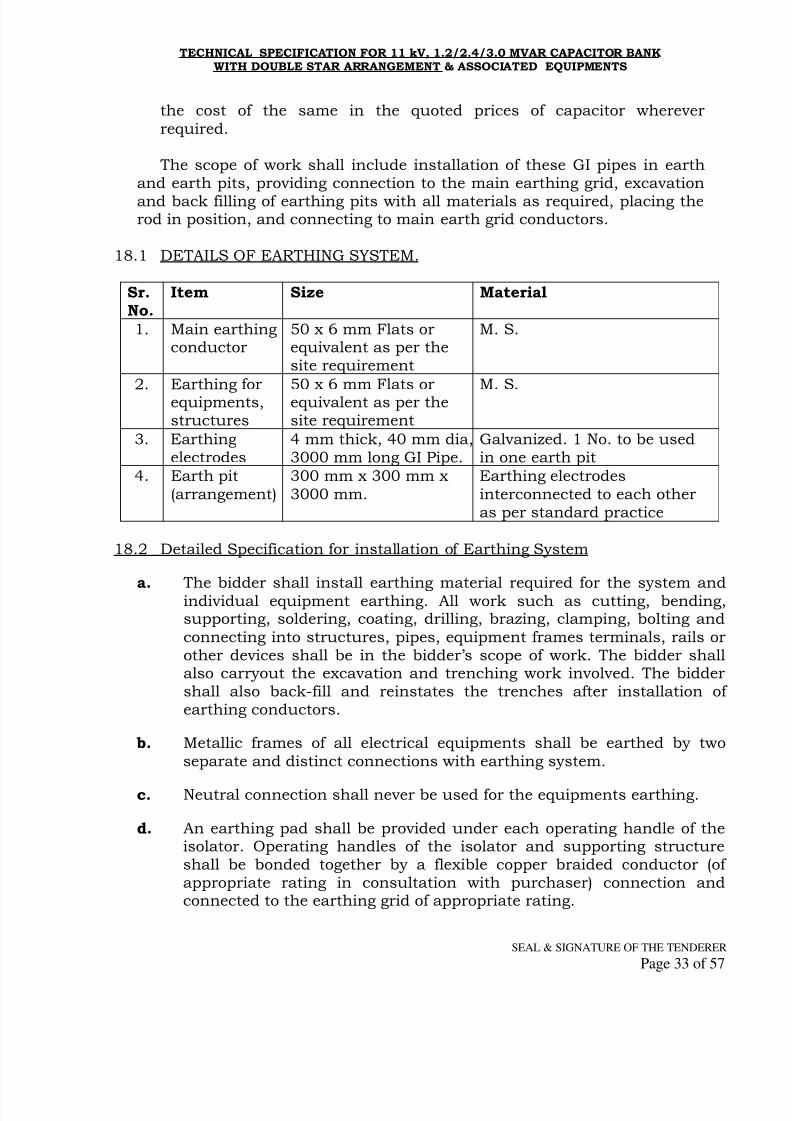
8/10/2019 A 5 11kV 1.2, 2.4 &3 MVAr Cap SpecInfra 240709
http://slidepdf.com/reader/full/a-5-11kv-12-24-3-mvar-cap-specinfra-240709 33/57
TECHNICAL SPECIFICATION FOR 11 kV, 1.2/2.4/3.0 MVAR CAPACITOR BANKWITH DOUBLE STAR ARRANGEMENT & ASSOCIATED EQUIPMENTS
SEAL & SIGNATURE OF THE TENDERER
Page 33 of 57
the cost of the same in the quoted prices of capacitor wherever
required.
The scope of work shall include installation of these GI pipes in earthand earth pits, providing connection to the main earthing grid, excavation
and back filling of earthing pits with all materials as required, placing therod in position, and connecting to main earth grid conductors.
18.1 DETAILS OF EARTHING SYSTEM.
Sr.No.
Item Size Material
1. Main earthingconductor
50 x 6 mm Flats orequivalent as per thesite requirement
M. S.
2. Earthing forequipments,structures
50 x 6 mm Flats orequivalent as per thesite requirement
M. S.
3. Earthingelectrodes
4 mm thick, 40 mm dia,3000 mm long GI Pipe.
Galvanized. 1 No. to be usedin one earth pit
4. Earth pit
(arrangement)
300 mm x 300 mm x
3000 mm.
Earthing electrodes
interconnected to each otheras per standard practice
18.2 Detailed Specification for installation of Earthing System
a.
The bidder shall install earthing material required for the system andindividual equipment earthing. All work such as cutting, bending,supporting, soldering, coating, drilling, brazing, clamping, bolting and
connecting into structures, pipes, equipment frames terminals, rails orother devices shall be in the bidder’s scope of work. The bidder shallalso carryout the excavation and trenching work involved. The biddershall also back-fill and reinstates the trenches after installation ofearthing conductors.
b. Metallic frames of all electrical equipments shall be earthed by two
separate and distinct connections with earthing system.
c. Neutral connection shall never be used for the equipments earthing.
d. An earthing pad shall be provided under each operating handle of theisolator. Operating handles of the isolator and supporting structureshall be bonded together by a flexible copper braided conductor (ofappropriate rating in consultation with purchaser) connection andconnected to the earthing grid of appropriate rating.

8/10/2019 A 5 11kV 1.2, 2.4 &3 MVAr Cap SpecInfra 240709
http://slidepdf.com/reader/full/a-5-11kv-12-24-3-mvar-cap-specinfra-240709 34/57
TECHNICAL SPECIFICATION FOR 11 kV, 1.2/2.4/3.0 MVAR CAPACITOR BANKWITH DOUBLE STAR ARRANGEMENT & ASSOCIATED EQUIPMENTS
SEAL & SIGNATURE OF THE TENDERER
Page 34 of 57
e. A separate earth electrode pit shall be provided adjacent to structures
supporting lightning arrester. Earth connections shall be as short andas straight as practicable.
f. On completion of the installation, continuity of all conductors and
efficiency of all bonds and joint shall be tested. The earth resistanceshall be tested in the presence of the Purchaser’s representative. Allequipments necessary for the test shall be arranged by the bidder.
g. The welding equipments and consumable items such as welding rods
required for installation of the earthing system shall be arranged by thebidder.
h. The earthing installation for the complete 11 KV capacitor installationsas described above shall finally be connected to the main earth mat ofthe sub station existing earthing system by the bidder. The connections
to main earthing system will have to be done at minimum of threepoints between the earthing system of Capacitor installation and main
earth mat of existing substations.
For earthing system of the installation all associated civil works as describedabove shall be within the scope of bidder.
19.0 Control Cables:
A. The copper control cable shall be of 1.1 KV grade L. T. cable withstranded untinned copper conductor, PVC insulated (Type A), colour
coded up to 5 cores,& by number coded above 5 cores, laid up withfillers and/or binder tape where necessary, provided with extruded
PVC inner sheath, single galvanized round steel wire armoured andprovided with PVC outer-sheath. Both outer & inner sheaths shallbe of type ST-1 as per IS: 5831-1984 and cable shall be conformingto IS: 1554(Part-1) -1988(amended up to date) & bearing ISI mark.
B. The aluminum control cable shall be of 1.1 KV grade L. T. cablewith stranded H2/H4 grade aluminum conductor, PVC insulated
(Type A), colour coded, laid up with fillers and/or binder tape wherenecessary, provided with extruded PVC inner sheath, single
galvanized round steel wire armoured and provided with PVC outer-sheath. Both outer & inner sheaths shall be of type ST-1 as per IS:5831-1984 and cable shall be conforming to IS: 1554(Part-1) -1988(amended up to date) & bearing ISI mark.
C. The cable shall be designed to withstand mechanical, electrical and
thermal stresses developed under the steady state and transient
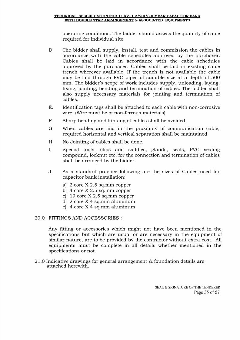
8/10/2019 A 5 11kV 1.2, 2.4 &3 MVAr Cap SpecInfra 240709
http://slidepdf.com/reader/full/a-5-11kv-12-24-3-mvar-cap-specinfra-240709 35/57
TECHNICAL SPECIFICATION FOR 11 kV, 1.2/2.4/3.0 MVAR CAPACITOR BANKWITH DOUBLE STAR ARRANGEMENT & ASSOCIATED EQUIPMENTS
SEAL & SIGNATURE OF THE TENDERER
Page 35 of 57
operating conditions. The bidder should assess the quantity of cable
required for individual site
D. The bidder shall supply, install, test and commission the cables inaccordance with the cable schedules approved by the purchaser.
Cables shall be laid in accordance with the cable schedulesapproved by the purchaser. Cables shall be laid in existing cabletrench wherever available. If the trench is not available the cable
may be laid through PVC pipes of suitable size at a depth of 500mm. The bidder’s scope of work includes supply, unloading, laying,
fixing, jointing, bending and termination of cables. The bidder shallalso supply necessary materials for jointing and termination ofcables.
E. Identification tags shall be attached to each cable with non-corrosivewire. (Wire must be of non-ferrous materials).
F. Sharp bending and kinking of cables shall be avoided.
G. When cables are laid in the proximity of communication cable,required horizontal and vertical separation shall be maintained.
H. No Jointing of cables shall be done.
I. Special tools, clips and saddles, glands, seals, PVC sealing
compound, locknut etc, for the connection and termination of cablesshall be arranged by the bidder.
J. As a standard practice following are the sizes of Cables used for
capacitor bank installation:a) 2 core X 2.5 sq.mm copper
b) 4 core X 2.5 sq.mm copperc) 19 core X 2.5 sq.mm copperd) 2 core X 4 sq.mm aluminume) 4 core X 4 sq.mm aluminum
20.0 FITTINGS AND ACCESSORIES :
Any fitting or accessories which might not have been mentioned in thespecifications but which are usual or are necessary in the equipment of
similar nature, are to be provided by the contractor without extra cost. Allequipments must be complete in all details whether mentioned in thespecifications or not.
21.0 Indicative drawings for general arrangement & foundation details areattached herewith.

8/10/2019 A 5 11kV 1.2, 2.4 &3 MVAr Cap SpecInfra 240709
http://slidepdf.com/reader/full/a-5-11kv-12-24-3-mvar-cap-specinfra-240709 36/57
TECHNICAL SPECIFICATION FOR 11 kV, 1.2/2.4/3.0 MVAR CAPACITOR BANKWITH DOUBLE STAR ARRANGEMENT & ASSOCIATED EQUIPMENTS
SEAL & SIGNATURE OF THE TENDERER
Page 36 of 57
ANNEXURE ‘I’
STANDARDS TO BE ADOPTED FOR CAPICATOR BANK.
Sr.
No.
Indian
Standard Title
International
Standard
1IS:13925
part
1.1998
Shunt capacitors for AC Powersystems having a rated voltage
above 1000V
-
2 IS:12672 Internal Fuses for Shunt capacitors -
3 IS:2099 Bushings for voltage above 1000V IEC:60137
4 IS:5553 Reactors IEC:60289
5. IS:13118 High Voltage AC Circuit Breakers IEC:60056
6. IS:9921AC Disconnectors (Isolators) &earthing switches
IEC:60129
7. IS:9920 High Voltage Switches IEC:60265
8. IS:2705High Voltage Current Transformers
IEC:60185
9. IS:3156High Voltage Potential Transformers
IEC:60186
10.IS 2544/1973
IS 5350(Part II )1973
Tests on post insulators forsystem with nominal voltage
higher than 1000V
IEC:60168
11. IS:2071 High Voltage tests IEC:60060
12. -
RIV measurements IEC
RecommendationsCISPR
13. IS:2609 Partial Discharge measurements IEC:60270
14. IS:3716Insulation co-ordination &
Application Guide.IEC:71
15. IS:1554Low Voltage Cables IEC: 245,228,229,
189,204.
16.IS: 3070
Draft
ETDC 30
Metal Oxide Surge ArrestorsDraft TC 37(Sec.)
62
17. IS:3231 Electrical Relays IEC:255
18. IS:11353 Control circuit wiring & Panels. -
19. -Hot Dip Galvanizing ISO 1459 &
ISO 1461
20. - Clearances in Air as per IE Rules -

8/10/2019 A 5 11kV 1.2, 2.4 &3 MVAr Cap SpecInfra 240709
http://slidepdf.com/reader/full/a-5-11kv-12-24-3-mvar-cap-specinfra-240709 37/57
TECHNICAL SPECIFICATION FOR 11 kV, 1.2/2.4/3.0 MVAR CAPACITOR BANKWITH DOUBLE STAR ARRANGEMENT & ASSOCIATED EQUIPMENTS
SEAL & SIGNATURE OF THE TENDERER
Page 37 of 57
Annexure-II ‘A’Schedule of Guaranteed Technical Particulars of Shunt Capacitor Bank
Technical Requirement for Sr.No
Particulars
1.2 MVAr
Cap.Bank
2.4 MVAr
Cap.Bank
3.0 MVAr
Cap.Bank
Offered
1. Type, Manufacturers Name &country of Manufacture.
2. Rated Voltage KV 12.65 12.65 12.65
3. Service Voltage KV 11 11 11
4. Rated Frequency Hz 50 50 50
5. MVAr of the Cap. Bank at ratedvoltage & Frequency
1.452 2.904 3.630
6. MVAr of the Cap. Bank atservice voltage & Frequency
1.2 2.4 3.0
7. Temperature Rise (over an
ambient of 40º C of the Cap.unit)
As per IS-13925, Part I 1998
8. Capacitance of the bank perphase in micro farads
28.88 57.76 43.31 &28.88
9. Rated line current Amps 66.26 132.53 99.40 &
66.27
10. Maximum permissiblecontinuous over load currentAmps
As per IS-13925, Part I 1998
11. Capacitor losses for individual
units Watts/KVAr
0.2 0.2 0.2
12. No. of Cap. units per CapacitorBank
6 12 15(stargroup of 9& 6 units)
13. Capacitor unit rating Kv 7.3 7.3 7.3
14. Capacitor unit rating kVAR 242 242 242
15. Max. capacitor inrush surgewith the proposed reactorAmps
Less than 100 times the ratedcurrent.
16. Discharge time with internal
discharge device
With in
600 Secs.
With in
600 Secs.
With in
600 Secs.
17. Min. elect. Clearances in thebank between phase to phase& live parts to earth in mm
As per Electricity Act 2003 & asper Indian Standards
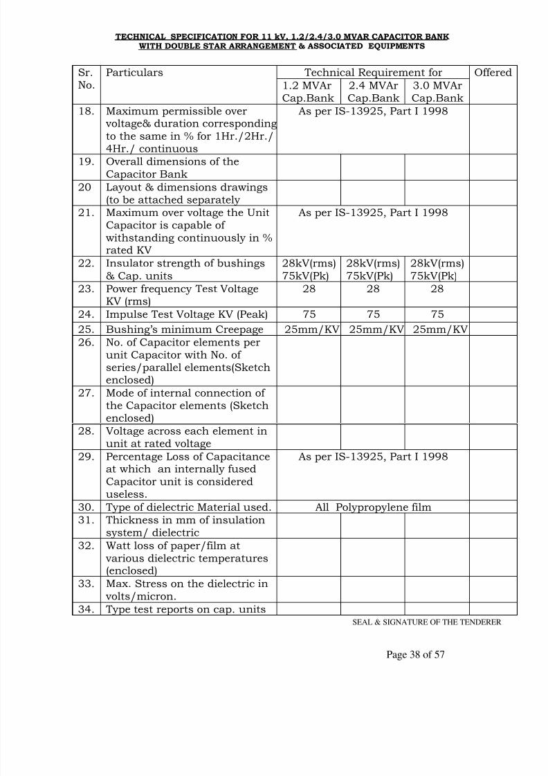
8/10/2019 A 5 11kV 1.2, 2.4 &3 MVAr Cap SpecInfra 240709
http://slidepdf.com/reader/full/a-5-11kv-12-24-3-mvar-cap-specinfra-240709 38/57
TECHNICAL SPECIFICATION FOR 11 kV, 1.2/2.4/3.0 MVAR CAPACITOR BANKWITH DOUBLE STAR ARRANGEMENT & ASSOCIATED EQUIPMENTS
SEAL & SIGNATURE OF THE TENDERER
Page 38 of 57
Technical Requirement forSr.No.
Particulars
1.2 MVArCap.Bank
2.4 MVArCap.Bank
3.0 MVArCap.Bank
Offered
18. Maximum permissible overvoltage& duration corresponding
to the same in % for 1Hr./2Hr./4Hr./ continuous
As per IS-13925, Part I 1998
19. Overall dimensions of the
Capacitor Bank
20 Layout & dimensions drawings(to be attached separately
21. Maximum over voltage the UnitCapacitor is capable of
withstanding continuously in %rated KV
As per IS-13925, Part I 1998
22. Insulator strength of bushings
& Cap. units
28kV(rms)
75kV(Pk)
28kV(rms)
75kV(Pk)
28kV(rms)
75kV(Pk)
23. Power frequency Test VoltageKV (rms)
28 28 28
24. Impulse Test Voltage KV (Peak) 75 75 75
25. Bushing’s minimum Creepage 25mm/KV 25mm/KV 25mm/KV
26. No. of Capacitor elements perunit Capacitor with No. ofseries/parallel elements(Sketchenclosed)
27. Mode of internal connection of
the Capacitor elements (Sketchenclosed)
28. Voltage across each element inunit at rated voltage
29. Percentage Loss of Capacitanceat which an internally fused
Capacitor unit is considereduseless.
As per IS-13925, Part I 1998
30. Type of dielectric Material used. All Polypropylene film
31. Thickness in mm of insulationsystem/ dielectric
32. Watt loss of paper/film atvarious dielectric temperatures(enclosed)
33. Max. Stress on the dielectric involts/micron.
34. Type test reports on cap. units
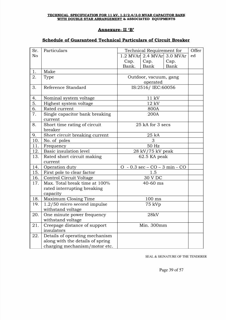
8/10/2019 A 5 11kV 1.2, 2.4 &3 MVAr Cap SpecInfra 240709
http://slidepdf.com/reader/full/a-5-11kv-12-24-3-mvar-cap-specinfra-240709 39/57
TECHNICAL SPECIFICATION FOR 11 kV, 1.2/2.4/3.0 MVAR CAPACITOR BANKWITH DOUBLE STAR ARRANGEMENT & ASSOCIATED EQUIPMENTS
SEAL & SIGNATURE OF THE TENDERER
Page 39 of 57
Annexure- II ‘B’
Schedule of Guaranteed Technical Particulars of Circuit Breaker
Technical Requirement for Sr.
No
Particulars
1.2 MVArCap.
Bank.
2.4 MVArCap.Bank
3.0 MVArCap.Bank
Offer
ed
1. Make
2. Type Outdoor, vacuum, gangoperated
3. Reference Standard IS:2516/ IEC:60056
4. Nominal system voltage 11 kV
5. Highest system voltage 12 kV
6. Rated current 800A
7. Single capacitor bank breakingcurrent
200A
8. Short time rating of circuitbreaker
25 kA for 3 secs
9. Short circuit breaking current 25 kA
10. No. of poles 3
11. Frequency 50 Hz
12. Basic insulation level 28 kV/75 kV peak
13. Rated short circuit makingcurrent
62.5 KA peak
14. Operation duty O - 0.3 sec – CO – 3 min - CO15. First pole to clear factor 1.5
16. Control Circuit Voltage 30 V DC
17. Max. Total break time at 100%
rated interrupting breakingcapacity
40-60 ms
18. Maximum Closing Time 100 ms
19. 1.2/50 micro second impulsewithstand voltage
75 kVp
20. One minute power frequency
withstand voltage
28kV
21. Creepage distance of supportinsulators
Min. 300mm
22. Details of operating mechanismalong with the details of spring
charging mechanism/motor etc.
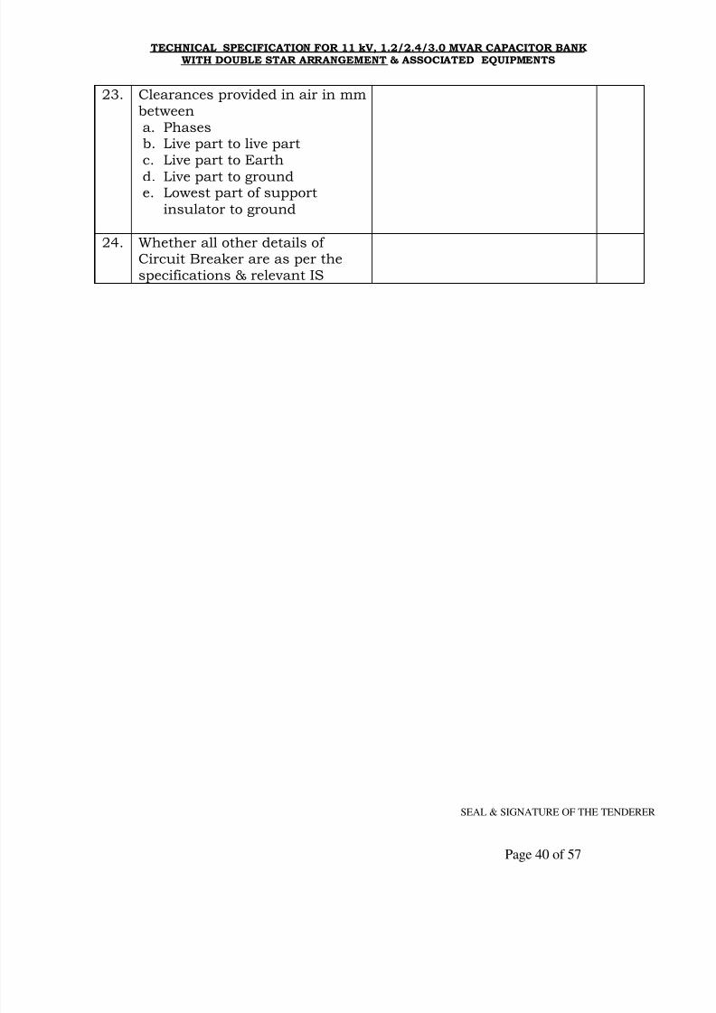
8/10/2019 A 5 11kV 1.2, 2.4 &3 MVAr Cap SpecInfra 240709
http://slidepdf.com/reader/full/a-5-11kv-12-24-3-mvar-cap-specinfra-240709 40/57
TECHNICAL SPECIFICATION FOR 11 kV, 1.2/2.4/3.0 MVAR CAPACITOR BANKWITH DOUBLE STAR ARRANGEMENT & ASSOCIATED EQUIPMENTS
SEAL & SIGNATURE OF THE TENDERER
Page 40 of 57
23. Clearances provided in air in mmbetweena. Phasesb. Live part to live partc. Live part to Earth
d. Live part to grounde. Lowest part of support
insulator to ground
24. Whether all other details ofCircuit Breaker are as per thespecifications & relevant IS

8/10/2019 A 5 11kV 1.2, 2.4 &3 MVAr Cap SpecInfra 240709
http://slidepdf.com/reader/full/a-5-11kv-12-24-3-mvar-cap-specinfra-240709 41/57
TECHNICAL SPECIFICATION FOR 11 kV, 1.2/2.4/3.0 MVAR CAPACITOR BANKWITH DOUBLE STAR ARRANGEMENT & ASSOCIATED EQUIPMENTS
SEAL & SIGNATURE OF THE TENDERER
Page 41 of 57
Annexure- II ‘C’ Schedule of Guaranteed Technical Particulars of Current Transformers
Technical Requirement for Sr.No
Particulars
1.2 MVAr
Cap.Bank
2.4 MVAr
Cap.Bank
3.0 MVAr
Cap.Bank
Offeed
1. Current Transformer1. Make
2. Type Outdoor, oil immersed/Dry Type
, dead tank
3. Reference Standard IS-2705
4. Rated voltage 11 kV
5. Rated Frequency 50 Hz
6. Rated primary current 200-100 or 300-150A
7. Rated secondary current 5 A
8. Ratio 200-100/5-5A or 300-150/5-5A
9. No. of cores 2
10. Rated output of each core 15 VA-15 VA
11. Class of accuracy Prot-5P10, Met-Class 0.5
12. Over current factor 25 kA for 3 Secs.
13. Power frequency withstand voltage 28 kV(rms)
14. Impulse withstand test voltage 75 kV(peak)

8/10/2019 A 5 11kV 1.2, 2.4 &3 MVAr Cap SpecInfra 240709
http://slidepdf.com/reader/full/a-5-11kv-12-24-3-mvar-cap-specinfra-240709 42/57
TECHNICAL SPECIFICATION FOR 11 kV, 1.2/2.4/3.0 MVAR CAPACITOR BANKWITH DOUBLE STAR ARRANGEMENT & ASSOCIATED EQUIPMENTS
SEAL & SIGNATURE OF THE TENDERER
Page 42 of 57
Annexure- II ‘D’Schedule of Guaranteed Technical Particulars of Neutral Current Transformer
Technical Requirement forSr.No.
Particulars
1.2 MVAr
Cap.Bank
2.4 MVAr
Cap.Bank
3.0
MVArNeutral Current Transformer
01 Make
02 Type Outdoor, Oil cooled / Dry Type(Polycrate / Epoxy)
03 Reference Standard IS-2705
04 Rated voltage 11 kV
05 Rated Frequency 50 Hz
06 Ratio 5/5A as per the requirement
07 No. of Cores 1
08 Rated output of each core 15 VA09 Class of accuracy Prot-5P10, Met-Class 0.5
10 Power frequency withstand 28 kV (rms)
11 Impulse withstand test voltage 75 kV (peak)
12 Over current factor 25 kA for 3 Secs.
13 Instrument security factor Not more than 5
Offered

8/10/2019 A 5 11kV 1.2, 2.4 &3 MVAr Cap SpecInfra 240709
http://slidepdf.com/reader/full/a-5-11kv-12-24-3-mvar-cap-specinfra-240709 43/57
TECHNICAL SPECIFICATION FOR 11 kV, 1.2/2.4/3.0 MVAR CAPACITOR BANKWITH DOUBLE STAR ARRANGEMENT & ASSOCIATED EQUIPMENTS
SEAL & SIGNATURE OF THE TENDERER
Page 43 of 57
Annexure- II ‘E’
Schedule of Guaranteed Technical Particulars of Series Reactors
Technical Requirement for Sr.
No
Particulars
1.2 MVArCap. Bank.
2.4 MVArCap.Bank
3.0 MVArCap.Bank
Offe
red
1. Make
2. Type Outdoor, Single phase, air cooled,air cored, Dry type, aluminum
wound, Non magnetically shielded
3. Reference Standard IS-5553 part-III/1990
4. % Impedance 6% or 0.2% of corresponding Cap Impedance.
5. System Voltage, Frequency,& number of phases
12KV,50Hz, 3 phase
6. Basic insulation level 28 kV/75 kV peak
7. Type of cooling AN
8. Overall dimensionsLength in mm
Width in mmHeight in mm
9. Over current factor 16.67 times for 2 Secs. & 130% of
rated current for continuousoperation
For 6% Reactor
10. Rated continuous throughput KVAr 15.44 X 6 30.88 X 6 77.2 X 3 or46.32 X 3 &
30.88 X 3
11. Rated current Amps /phase
34.63 69.27 -
12. Impedance Ohms/Phase
13. Load losses in KW for 3phases
For 0.2% Reactor
14. Rated continuousthrough put KVAr
0.48 X 6 0.97 X 6 1.452 X 3
0.97 X 3
15. Rated current Amps /phase
33.13 66.27 99.40 &66.27
16. Impedance Ohms/Phase
17. Load losses in KW for 3phases

8/10/2019 A 5 11kV 1.2, 2.4 &3 MVAr Cap SpecInfra 240709
http://slidepdf.com/reader/full/a-5-11kv-12-24-3-mvar-cap-specinfra-240709 44/57
TECHNICAL SPECIFICATION FOR 11 kV, 1.2/2.4/3.0 MVAR CAPACITOR BANKWITH DOUBLE STAR ARRANGEMENT & ASSOCIATED EQUIPMENTS
SEAL & SIGNATURE OF THE TENDERER
Page 44 of 57
Annexure- II ‘F’Schedule of Guaranteed Technical Particulars of Lightening Arrestors
Technical Requirement for Sr.
No
Particulars
1.2 MVArCap.Bank.
2.4 MVArCap.Bank
3.0 MVArCap.Bank
Offer
ed
1. Make
2. Type Outdoor type, Station Class, MetalOxide, Gapless, Single unit.
3. Reference Standard IS:3070 (Part-1) / 1985
IS:3070 (Part-3) / 1993
4. Rated voltage kV 9
Rated Frequency 50 Hz
5. Max. Continuous OperatingVoltage (M.C.O.V) in KV rms
8
6. Nominal Discharge Currentcorresponding to 8/20 microseconds
10 KA
7. Type of mounting Pedestal type
8. Connection clearancea) between phase to earth
b) between phase to phase
230 mm.
340 mm.
9. Long duration discharge
class
III
10. Max. Radio Interferencevoltage when energized at
M.C.O.V. (micro-volts)
PD less than 50 pC
11. Requirement for pressurerelief test min. prospectivesymmetrical fault current
(KA rms)
Class-A
12. Minimum Creepage Distanceof arrestor housing (mm)
340
13 Terminal connectors Suitable for ACSR PantherConductor
15. Protective characteristics ofArrestors
As per IEC 99-4

8/10/2019 A 5 11kV 1.2, 2.4 &3 MVAr Cap SpecInfra 240709
http://slidepdf.com/reader/full/a-5-11kv-12-24-3-mvar-cap-specinfra-240709 45/57
TECHNICAL SPECIFICATION FOR 11 kV, 1.2/2.4/3.0 MVAR CAPACITOR BANKWITH DOUBLE STAR ARRANGEMENT & ASSOCIATED EQUIPMENTS
SEAL & SIGNATURE OF THE TENDERER
Page 45 of 57
Annexure-II ‘G’Schedule of Guaranteed Technical Particulars of Isolators
Technical Requirement for Sr.No
Particulars
1.2 MVAr
Cap.Bank.
2.4 MVAr
Cap.Bank
3.0 MVAr
Cap.Bank
Offered
1. Make
2. Type Outdoor type, Center rotating,Double break, 3 Pole Gang
operated, With earth blade &without earth blade
3. Reference Standard IS-9921-1981
4. Rated voltage kV 12
5. Frequency Hz 50
6. Continuous current rating 800 Amps
7. Rated short time currentrating for 3 sec
25 KA(rms)63 KA (peak)
8. Maximum temperature riseover specified ambient
temperature of 40º C
With in permissible limit as perIS- 9921
9. 1.2/50 micro second fullwave positive and negative
impulse withstand voltagea) To earth & between poles
KV(peak)
b)Across the isolatingdistance for main blades
KV(peak)
75
95
10. One minute Power Frequencywithstand voltagea) To earth & between poles
KV(rms)b) Across the isolating
distance for main blades KV(rms)
28
38
11. Type of main contacts High pressure Banking type
12. Type of arcing contacts Make before and break after13. Material of contacts
a) Arcing
b) Mainc) contacts
G.I.
HDEC Pipesilver plated
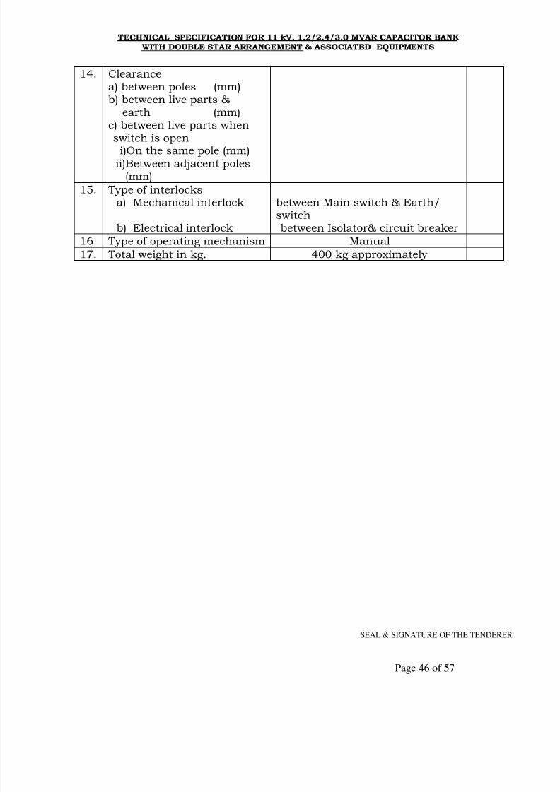
8/10/2019 A 5 11kV 1.2, 2.4 &3 MVAr Cap SpecInfra 240709
http://slidepdf.com/reader/full/a-5-11kv-12-24-3-mvar-cap-specinfra-240709 46/57
TECHNICAL SPECIFICATION FOR 11 kV, 1.2/2.4/3.0 MVAR CAPACITOR BANKWITH DOUBLE STAR ARRANGEMENT & ASSOCIATED EQUIPMENTS
SEAL & SIGNATURE OF THE TENDERER
Page 46 of 57
14. Clearancea) between poles (mm)b) between live parts &
earth (mm)c) between live parts when
switch is openi)On the same pole (mm)
ii)Between adjacent poles(mm)
15. Type of interlocksa) Mechanical interlock
b) Electrical interlock
between Main switch & Earth/switchbetween Isolator& circuit breaker
16. Type of operating mechanism Manual
17. Total weight in kg. 400 kg approximately

8/10/2019 A 5 11kV 1.2, 2.4 &3 MVAr Cap SpecInfra 240709
http://slidepdf.com/reader/full/a-5-11kv-12-24-3-mvar-cap-specinfra-240709 47/57
TECHNICAL SPECIFICATION FOR 11 kV, 1.2/2.4/3.0 MVAR CAPACITOR BANKWITH DOUBLE STAR ARRANGEMENT & ASSOCIATED EQUIPMENTS
SEAL & SIGNATURE OF THE TENDERER
Page 47 of 57
Annexure-II ‘H’
Schedule of Guaranteed Technical Particulars of Control and Relay Panel
Technical Requirement for Sr.
No.
Particulars
1.2 MVArCap.Bank
2.4 MVArCap.Bank
3.0 MVArCap.Bank
Offer
ed
1. Cubicle Simplex type
2. Mimic Diagram
3. 12 window static Annunciatorwith relays etc.
Minilec or equivalent make
4. Accept, Reset, Lamp test, &Sound cancel Push Buttons
(4nos.)
Technic or equivalent make
5. 96 X 96 mm Digital Ammeterwith selector switch.
AE or equivalent make
6. 96 X 96 mm Digital Voltmeterwith selector switch
AE or equivalent make
7. Digital MVAr meter AE or equivalent make
8. Digital Power factor meter AE or equivalent make
9. 12 way control switch for
circuit breaker
Kaycee/Recom make or equivalent
10. Numeric type 2 O/C + 1 E/FIDMT relay
ABB/ER make or equivalent
11. Numeric type Over VoltageRelay
ABB/ER make or equivalent
12. Numeric type Under VoltageRelay ABB/ER make or equivalent
13. Numeric type Unbalancedprotection (Neutral currentsensing) relay
ABB/ER make or equivalent
14. Static type Trip circuitsupervision relay
ABB/ER make or equivalent
15. Static type High speed relay ABB/ER make or equivalent
16. Static type time delay relay ABB/ER make or equivalent
17. DC control ON/OFF switch. Kaycee/Recom make or equivalent
18. Neon type indicating lamps for
breaker & Isolator status(12nos.)
Technic or equivalent make
19. Semaphore indicator for
circuit breaker & Isolator(3nos.)
Dav make or equivalent

8/10/2019 A 5 11kV 1.2, 2.4 &3 MVAr Cap SpecInfra 240709
http://slidepdf.com/reader/full/a-5-11kv-12-24-3-mvar-cap-specinfra-240709 48/57
TECHNICAL SPECIFICATION FOR 11 kV, 1.2/2.4/3.0 MVAR CAPACITOR BANKWITH DOUBLE STAR ARRANGEMENT & ASSOCIATED EQUIPMENTS
SEAL & SIGNATURE OF THE TENDERER
Page 48 of 57
Sr.No
Particulars Technical Requirement Offered
20. Timer for breaker closingInterlock
Reputed make
21. Test terminal block CD make or equivalent
22. Lead Power factor relay Beluk/Alacrity make or equivalent
23. Set of fuses for controlcircuits
Reputed make
24. Illumination lamp with doorlimit switch
Reputed make
25. Space heater & toggle switch Reputed make
26. 3 Pin plug & socket Reputed make
27. Earth Bus 25 X 6 mm Reputed make
28. Set of disconnecting typeterminal block
Reputed make
29. Set of non disconnecting typeterminal block
Reputed make
30. Bell & Hooter for
annunciation trip & non-tripalarm
Reputed make
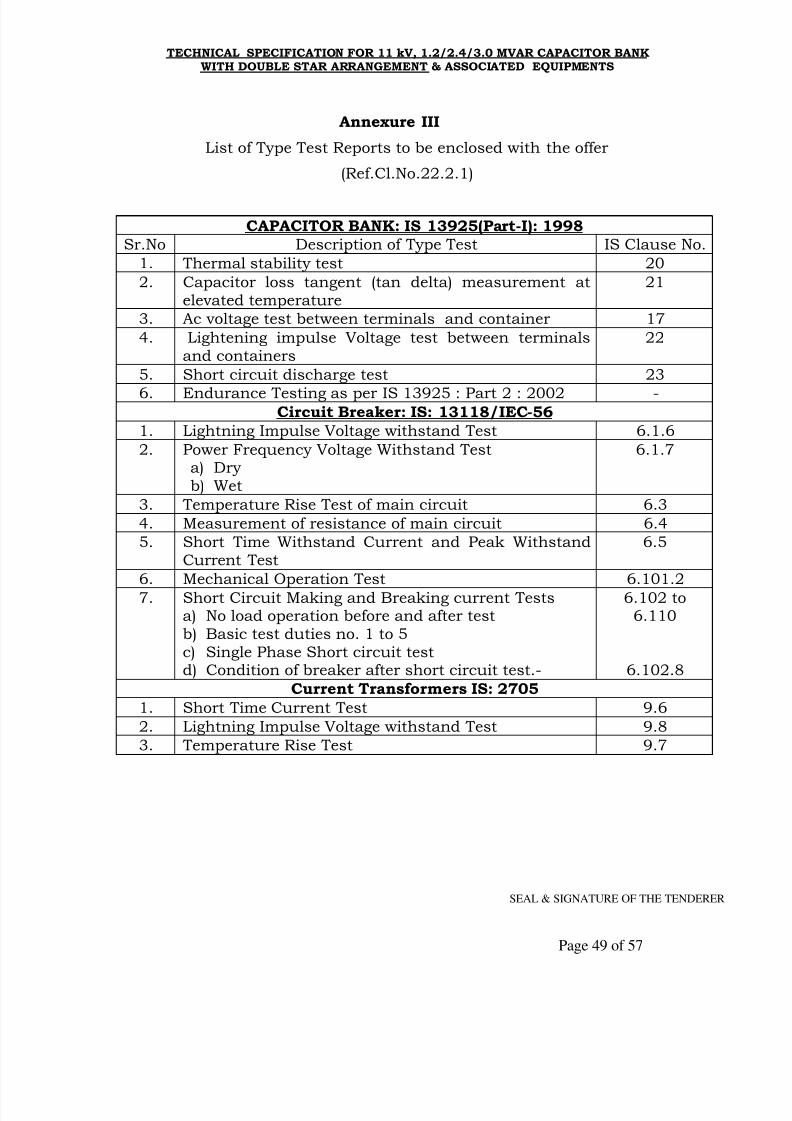
8/10/2019 A 5 11kV 1.2, 2.4 &3 MVAr Cap SpecInfra 240709
http://slidepdf.com/reader/full/a-5-11kv-12-24-3-mvar-cap-specinfra-240709 49/57
TECHNICAL SPECIFICATION FOR 11 kV, 1.2/2.4/3.0 MVAR CAPACITOR BANKWITH DOUBLE STAR ARRANGEMENT & ASSOCIATED EQUIPMENTS
SEAL & SIGNATURE OF THE TENDERER
Page 49 of 57
Annexure III
List of Type Test Reports to be enclosed with the offer
(Ref.Cl.No.22.2.1)
CAPACITOR BANK: IS 13925(Part-I): 1998Sr.No Description of Type Test IS Clause No.
1. Thermal stability test 20
2. Capacitor loss tangent (tan delta) measurement atelevated temperature
21
3. Ac voltage test between terminals and container 17
4. Lightening impulse Voltage test between terminalsand containers
22
5. Short circuit discharge test 23
6. Endurance Testing as per IS 13925 : Part 2 : 2002 -Circuit Breaker: IS: 13118/IEC-56
1. Lightning Impulse Voltage withstand Test 6.1.6
2. Power Frequency Voltage Withstand Testa) Dryb) Wet
6.1.7
3. Temperature Rise Test of main circuit 6.3
4. Measurement of resistance of main circuit 6.4
5. Short Time Withstand Current and Peak WithstandCurrent Test
6.5
6. Mechanical Operation Test 6.101.2
7. Short Circuit Making and Breaking current Testsa) No load operation before and after testb) Basic test duties no. 1 to 5c) Single Phase Short circuit testd) Condition of breaker after short circuit test.-
6.102 to6.110
6.102.8
Current Transformers IS: 2705
1. Short Time Current Test 9.6
2. Lightning Impulse Voltage withstand Test 9.8
3. Temperature Rise Test 9.7

8/10/2019 A 5 11kV 1.2, 2.4 &3 MVAr Cap SpecInfra 240709
http://slidepdf.com/reader/full/a-5-11kv-12-24-3-mvar-cap-specinfra-240709 50/57
TECHNICAL SPECIFICATION FOR 11 kV, 1.2/2.4/3.0 MVAR CAPACITOR BANKWITH DOUBLE STAR ARRANGEMENT & ASSOCIATED EQUIPMENTS
SEAL & SIGNATURE OF THE TENDERER
Page 50 of 57
Sr.No Description of Type Test IS Clause No.
Series Reactors IS: IS-5553
1. Measurement of winding resistance 9.2 (a)
2. Measurement of Insulation resistance 9.2 (b)
3. Measurement of impedance of continuous current (if
applicable)
9.2 ©
4. Measurement of Loss (if applicable) 9.2 (d)
5. Separate-source voltage withstand test 9.2 (e)
6. Induced over voltage withstand test 9.2 (f)
7. Temperature-rise test at rated continuous current 9.2 (h)
8. Lightening Impulse test 9.2 (j)
Lightening Arrestors: IS-3070(Part-3):19931. Insulation withstand test on arrestor housing 6.2
2. Residual voltage test 6.4
3. Long duration current impulse withstand Test 6.5
4. Operating duty test 6.65. Pressure relief test 6.7
6. Tests of arrestor disconnectors 6.8
7. Artificial pollution test on porcelain housed arrestors Annex.J
8. Temperature cycle test on hollow porcelain housings Annex.H
9. Porosity test Annex.H
10. Galvanizing test on exposed ferrous metal parts Annex.H
Isolators (with and without E.B.) IS:9921 (Part IV)
1. Lightning Impulse Voltage withstand Test 3.1.6
2. Power Frequency Voltage Withstand Testa) Dryb) Wet
3.1.8
3. Temperature Rise Test 3.1.1
4. Short Time Withstand Current and Peak WithstandCurrent Test
3.3
5. Mechanical Endurance Test 3.5
Control & Relay Panel
1 Degree of protection test 5.3.1.3
2 Induce over voltage test

8/10/2019 A 5 11kV 1.2, 2.4 &3 MVAr Cap SpecInfra 240709
http://slidepdf.com/reader/full/a-5-11kv-12-24-3-mvar-cap-specinfra-240709 51/57
TECHNICAL SPECIFICATION FOR 11 kV, 1.2/2.4/3.0 MVAR CAPACITOR BANKWITH DOUBLE STAR ARRANGEMENT & ASSOCIATED EQUIPMENTS
SEAL & SIGNATURE OF THE TENDERER
Page 51 of 57
SCHEDULE - `L'
SCHEDULE OF TENDERER'S EXPERIENCE
Tenderer shall furnish here a list of similar orders executed /underexecution by him to whom a reference may be made by Purchaser incase he considers such a reference necessary.
-----------------------------------------------------------------------------------Sr. Name of the Value of Period of Name & address to
No. client and order supply and whom referenceDescription Commissioning may be madeof itemsordered.
-----------------------------------------------------------------------------------
1 2 3 4 5-----------------------------------------------------------------------------------
NAME OF FIRM ___________________________________
NAME & SIGNATURE OF THE TENDERER________________
DESIGNATION ____________________________________
DATE ___________________________________________
8/10/2019 A 5 11kV 1.2, 2.4 &3 MVAr Cap SpecInfra 240709
http://slidepdf.com/reader/full/a-5-11kv-12-24-3-mvar-cap-specinfra-240709 52/57
TECHNICAL SPECIFICATION FOR 11 kV, 1.2/2.4/3.0 MVAR CAPACITOR BANKWITH DOUBLE STAR ARRANGEMENT & ASSOCIATED EQUIPMENTS
SEAL & SIGNATURE OF THE TENDERER
Page 52 of 57
SCHEDULE - ̀ F’ Proforma of Undertaking
We hereby confirm that Capacitor Banks have been supplied by us to
M.S.E.D.C.L./erstwhile M.S.E.B. against earlier Order No._______________
Dated ___________ and the type test certificates thereof were approved by
C.E.(Dist.) vide Letter No.____________________________ Dated __________
copy enclosed.
NAME OF FIRM ___________________________________
NAME & SIGNATURE OF THE TENDERER________________
DESIGNATION ____________________________________
DATE ___________________________________________
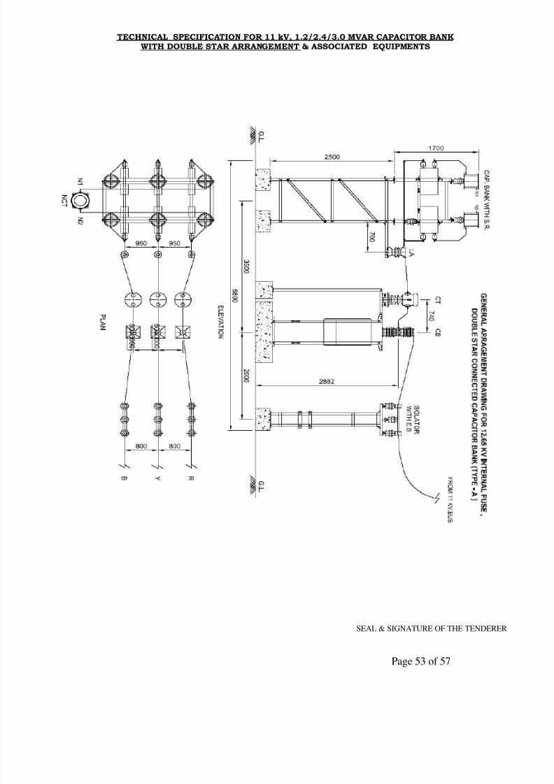
8/10/2019 A 5 11kV 1.2, 2.4 &3 MVAr Cap SpecInfra 240709
http://slidepdf.com/reader/full/a-5-11kv-12-24-3-mvar-cap-specinfra-240709 53/57
TECHNICAL SPECIFICATION FOR 11 kV, 1.2/2.4/3.0 MVAR CAPACITOR BANKWITH DOUBLE STAR ARRANGEMENT & ASSOCIATED EQUIPMENTS
SEAL & SIGNATURE OF THE TENDERER
Page 53 of 57
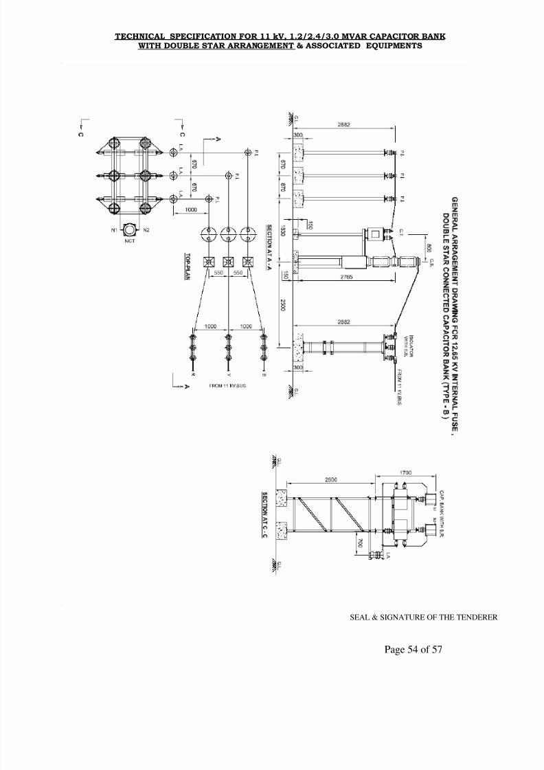
8/10/2019 A 5 11kV 1.2, 2.4 &3 MVAr Cap SpecInfra 240709
http://slidepdf.com/reader/full/a-5-11kv-12-24-3-mvar-cap-specinfra-240709 54/57
TECHNICAL SPECIFICATION FOR 11 kV, 1.2/2.4/3.0 MVAR CAPACITOR BANKWITH DOUBLE STAR ARRANGEMENT & ASSOCIATED EQUIPMENTS
SEAL & SIGNATURE OF THE TENDERER
Page 54 of 57
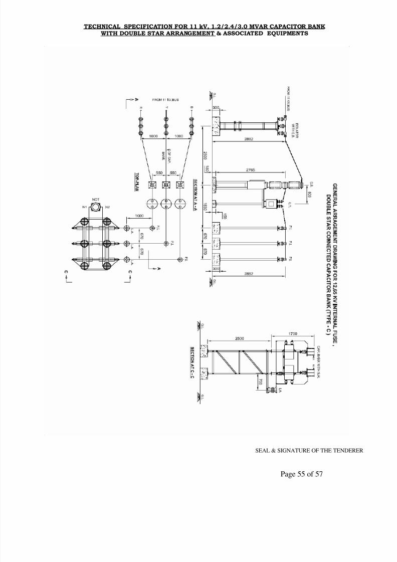
8/10/2019 A 5 11kV 1.2, 2.4 &3 MVAr Cap SpecInfra 240709
http://slidepdf.com/reader/full/a-5-11kv-12-24-3-mvar-cap-specinfra-240709 55/57
TECHNICAL SPECIFICATION FOR 11 kV, 1.2/2.4/3.0 MVAR CAPACITOR BANKWITH DOUBLE STAR ARRANGEMENT & ASSOCIATED EQUIPMENTS
SEAL & SIGNATURE OF THE TENDERER
Page 55 of 57
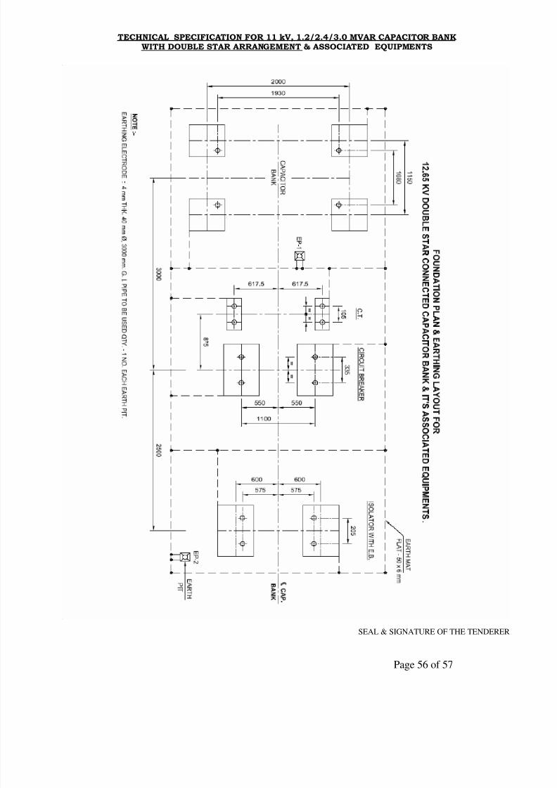
8/10/2019 A 5 11kV 1.2, 2.4 &3 MVAr Cap SpecInfra 240709
http://slidepdf.com/reader/full/a-5-11kv-12-24-3-mvar-cap-specinfra-240709 56/57
TECHNICAL SPECIFICATION FOR 11 kV, 1.2/2.4/3.0 MVAR CAPACITOR BANKWITH DOUBLE STAR ARRANGEMENT & ASSOCIATED EQUIPMENTS
SEAL & SIGNATURE OF THE TENDERER
Page 56 of 57

8/10/2019 A 5 11kV 1.2, 2.4 &3 MVAr Cap SpecInfra 240709
http://slidepdf.com/reader/full/a-5-11kv-12-24-3-mvar-cap-specinfra-240709 57/57
TECHNICAL SPECIFICATION FOR 11 kV, 1.2/2.4/3.0 MVAR CAPACITOR BANKWITH DOUBLE STAR ARRANGEMENT & ASSOCIATED EQUIPMENTS


