anexo f.- documentos relevantes detectados en la ......controlled reactor (tcr) provides inductive...
TRANSCRIPT

1/155
ANEXO F.- Documentos relevantes detectados en la búsqueda de bases internacionales. NÚMERO
PUBLICACIÓN TÍTULO PRIORIDAD INVENTOR SOLICITANTE RESUMEN
¿EN MÉXICO?
FILTRO ACTIVO DE POTENCIA (APF)
CN102624011 Distributed generation reactive compensation device 2012CN-0125371 20120426
CHAO MENG; YONGQIANG HONG; PO LI
UNIVERSITY OF XIAMEN
The invention discloses a distributed generation reactive compensation device, relating to a grid compensation device and providing a distributed generation reactive compensation device which can operate stably and cannot generate resonance. The distributed generation reactive compensation device is provided with a thyristor controlled reactor, a fixed capacitor group, an active power filter and a control circuit, wherein the thyristor controlled reactor is directly connected with a power grid in parallel; the fixed capacitor group is connected with the active power filter in series and is then connected to the power gird; a driving pulse signal end of the control circuit is respectively connected with the thyristor controlled reactor and the active power filter. The control circuit can be provided with a grid voltage and current sampling circuit, a digital signal processing (DSP) controller, an IPM (Intelligent Power Module) driving circuit, a thyristor driving circuit, a liquid crystal display and a protection circuit.
NO
CN202002990 Comprehensive experiment system of power quality control device
2011CN-U095673 20110402
SHENG LI; ZHIWEN GUO; HUA XIA
HUATIAN ENGINEERING & TECHNOLOGY MCC
The utility model discloses a comprehensive experiment system of a power quality control device, which comprises three transformers, a parallel electric power filter group, a static reactive generator, a thyristor switching filter group, a thyristor controlled reactor, an active electric power filter, an online power quality analyzer and other detection devices, and is also provided with a pure water airtight heat dissipation circulating system, an online alternating-current uninterruptible alternating current power supply of being 220V and an online direct-current uninterruptible power supply of being 100V. The comprehensive experiment system has the benefits of being capable of simulating the actual use condition of various power quality control devices, providing experimental conditions for research and development and product test, reducing the power
NO

2/155
consumption in an experiment by utilizing the self-function of the system, reducing the experimental cost and the electric pollution, and simultaneously having the capability of providing necessary experimental conditions for a test on performances of special components.
CN101635461 Combined compensation system of injection-type hybrid active power filter and static var compensator
2009CN-0043552 20090531
AN LUO; FUJUN MA; CHUANPING WU; XIANYONG XU; LU FANG; XIAO YANG; WEN WANG; JUAN SUN
HUNAN UNIVERSITY
The invention discloses a combined compensation system of an injection-type hybrid active power filter and a static var compensator. The combined compensation system is composed of the injection-type hybrid active power filter and the static var compensator, wherein, the injection-type hybrid active power filter is composed of an uncontrollable rectifier bridge, an inverter, an output filter reactor, a coupling transformer, an injection branch and a high-pass filter, a first capacitor (C1) and a first inductor (L1) in the injection branch form a first harmonic resonance circuit, and forms a triple resonance injection branch with an injection capacitor (C[F]), and a second capacitor (C[G]), a second inductor (L[G]) and a resistor (R[G]) form a second order damped high-pass filter; the static var compensator is a thyristor controlled reactor; and an output terminal of the injection capacitor (C[F]) is connected with the high-pass filter, the static var compensator and electric grids. In the combined compensation system, one compensation system is respectively arranged at two feeding sections of an electric traction system, which can realize comprehensive control on reactive, harmonics and negative sequence compensation in electric railways.
NO
CN1734879 US2007014132 US7352597
Comprehensive power quality controller for substation in power system
2005CN-0042946 20050718
WANG ZHAOAN; WANG YUE; YANG JUN; ZHANG XIAO; LEI WANJUN; SI WEIBIN; TANG XIAOHUA; DONG QIANG
XI'AN JIAOTONG UNIVERSITY
This invention disclosed is a comprehensive power quality controller for substation in the electric power system and includes a Thyristor Controlled Reactor (TCR), pure tuned passive filter Z<SUB>f</SUB>, additional inductor L active power filter (APF), and a coupling transformer. The Thyristor Controlled Reactor (TCR) provides inductive reactive power and controls the active power filter (APF) as the current source, it is connected with the additional inductor L<SUB>a </SUB>in parallel via the coupling transformer, then connected to the passive filter Z<SUB>f </SUB>in serial to
NO

3/155
consist a hybrid power filter system, which is connected to the power grid via the circuit breaker or thyristor. The comprehensive filter system provides required capacitive reactive power and filters the harmonic produced by the load and TCR system itself. Because the capacity of the active power filter (APF) is very small which is less than 1% of the harmonic source capacity, so it is a solution with low cost but simple and reliable control mode. It can suppress influence on the passive filter by the "background harmonic" of the substation and prevent the resonance occurred between the passive filter and power grid impedance.
CN201466732 Static var compensator for steelmaking electric arc furnace
2009CN-U070704 20090420
JIANJUN GU; BAONIAN HU; KAI LI; YONGZHENG ZHENG
BAOSHAN IRON & STEEL
The utility model discloses a static var compensator for a steelmaking electric arc furnace, which consists of a thyristor controlled reactor (2) and a filter, and the thyristor controlled reactor is connected with the filter in parallel; the thyristor controlled reactor is a three-phase main circuit with the triangular connection way, and each-phase circuit consists of a thyristor (7) and a reactor which are arranged in a pair and in inverse parallel connection; and the filter is an injection-type hybrid shunt active power filter (1) comprising an active power filter (3) and a passive filter(6), the active power filter is series-connected with an inductor (4) and then connected into a primary side of an isolation transformer (5), and a secondary side of the isolation transformer is parallel-connected with a series resonance circuit consisting of a capacitor C11 and the reactor L1, then series-connected with the capacitor C12 and further parallel-connected with the passive filter to be connected into a power grid. The static var compensator can realize the comprehensive harmonic and reactive power dynamic compensation, improve the filter effect of the static var compensator and improve the stability of the device.
NO
CN102842909 Method for controlling power electronic hybrid system 2012CN-0336074 20120912
SHUAI ZHIKANG; TU CHUNMING; PAN HONGBIN; YAO PENG; JIANG LING; DAI
HUNAN UNIVERSITY
The invention discloses a method for controlling a power electronic hybrid system. The method comprises a power electronic hybrid control system comprising an active power filter and a static var compensator, wherein the static var compensator comprises a passive power filter group and a
NO

4/155
XIAOZONG; CHU LANG; XIAO FAN; ZHANG YANG
thyristor control reactor (TCR); and the active power filter, the passive power filter group and the TCR access between a power grid and loads connected with the power grid in sequence. The passive power filter and the active power filter are used jointly to perform harmonic suppression on high-voltage busbars; and the static var compensator is used to perform reactive compensation, so that delay compensation and online control are realized, control accuracy is enhanced, tracking performance is improved, electric energy loss of the power grid is reduced, and pollution of the power grid is purified.
CN102545235 Triangular connection type comprehensive compensation system integrated with cascaded active filter and reactive compensator
2010CN-0624030 20101231
XINJIAN JIANG; CONGZHE GAO; YONGDONG LI; JUNLING CHEN; PING WANG
INSTITUTE OF ELECTRICAL ENGINEERING CAS TSINGHUA UNIVERSITY
The invention discloses a triangular connection type comprehensive compensation system integrated with a cascaded active filter and a reactive compensator. The system comprises triangular connection type N-grade cascaded converters and a three-phase filter inductor connected with each N-grade cascaded converter; triangular connection type thyristor reactors and star-shaped connection type thyristors are used for switching the reactive compensator composed of fixed capacitors; and the triangular connection type N-grade cascaded converters and the reactive compensator are connected in parallel between a connection node and a ground node of an input power grid voltage and a load. According to the system provided by the invention, reactive power and harmonic current in a medium-voltage power grid are subjected to dynamic compensation and the efficiency of the power grid is improved; when the system is used for compensating, the system has no negative influences on the power grid, and has advantages of stable system, simple structure, strong stability and flexibility in compensation.
NO
CN101202448 CN100544155
Harmonic based on APF and SVC and reactive-load dynamic state compensating system and frequency-dividing phase-splitting electrical current control method
2007CN-0192665 20071219
AN LUO; WEI ZHAO; ZHIKANG SHUAI; ZHEN LEI; QIANG LI; ZHONGHUA JIANG
HUNAN UNIVERSITY
The invention discloses a harmonic and reactive dynamic comprehensive compensation system which is based on APF and SVC, comprising an independent resonance injection active power filter APF, a thyristor controlled reactor TCR and a mechanically switched capacitor MSC. The thyristor controlled reactor TCR is arranged beside a power network;
NO

5/155
the mechanically switched capacitor MSC is arranged beside a load; the independent injection active power filter APF is arranged between the TCR and the MSC; meanwhile, a frequency-dividing and phase-separating method which is applicable to the comprehensive compensation system is disclosed. The system of the invention can implement dynamic real-time tracking compensation treatment for power network harmonic current and reactive power; the current control method which is adaptable for the system overcomes the shortage of great coupling between the APF and the TCR when a traditional ipiq method is adopted, greatly reduces the interplaying of the control performances between the TCR and the APF, thus improving the reliability and control precision of the system.
CN1665095 A comprehensive electric energy quality regulator 2005CN-0018430 20050324
DING HONGFA; DUAN XIANZHONG; ZHU QINGCHUN
HUAZHONG UNIVERSITY OF SCIENCE & TECHNOLOGY
The invention discloses a synthetic electric-energy quality regulator, comprising series and parallel active filter units, measuring unit and control units, where the parallel active filter unit is connected in series with parallel passive filter unit to compose a parallel unit, which is connected to the system; the series active filter unit is under the control of the series control unit and outputs sinusoidal current by the driving of all the switches of the first inverter unit; the parallel active filter unit is controlled by the parallel control unit and outputs an specific voltage by the driving of all the switches of the second inverter unit; the parallel passive filter unit is a LC filter circuit to provide a low resistance pass for harmonic current of a load and compensate reactive power of the load. The invention overcomes the shortages of large capacity and high manufacturing cost of the original parallel active filter; and has a better tracking effect and a better compensating effect, as well as higher performance/cost trade-off.
NO
CN101588069 Harmonic-var comprehensive compensation system based on two-way dynamic reactive power compensation devices
2009CN-0023048 20090626
QIANG XU; JIANRONG ZHANG; QIHUA WANG; PENG GAO
XI AN SINPOWER ELECTRICAL
The invention relates to a harmonic-var comprehensive compensation system based on two-way dynamic reactive power compensation devices. The system consists of a mechanically switched capacitor MSC, a static var generator SVG and an active power filter APF which are connected with a power network 1. The system uses the SVG to replace
NO

6/155
a thyristor controlled reactor TCR in the prior harmonic-var comprehensive compensation system, and as the SVG generates reactive power through electric-energy transformation to perform var compensation, the SVG does not need large-capacity reactors, capacitors and other energy storage elements. Therefore, the capacity of the MSC and the SVG is reduced by half at least; system volume is effectively reduced; and system cost is lowered. Meanwhile, as the SVG uses a full-controlled switching device IGBT, the SVG is fast in response and has the system response time which is less than 20 ms and much superior to that of the TCR. In addition, as the SVG does not produce harmonic current, the capacity of the APF is reduced, thus the volume and cost of the system are further reduced.
CN203151098 APF active electric power filters complete equipments( [Machine Translation])
2013CN-U150883 20130329
HUADIAN REPOWER ELECTRIC POWER TECHNOLOGY
This utility model has publicized one kind of APF active electric power filters complete equipments, is equipped in order the electric interlock signal circuit, the control circuit and driving circuit, moreover is equipped with the fuse, contact device, reactor, the IGBT invertor and direct-current capacitor that establishes contacts in order, is equipped with the limiting resistor with state the contact device and company in the electric circuit; Is equipped with current transformer A between the contact device and reactor, on the electrical network input circuit that in the user load is equipped with current transformer B, states the fuse with state the electrical network input circuit connection through the switch, current transformer A, B and signal circuit clear signal connection, the driving circuit and IGBT invertor carried on the pilot connection, was equipped with the power circuit with state the direct-current capacitor's both sides to carry on the electric interlock, this power circuit and with stated the control circuit and driving circuit carries on the power supply connection. This utility model is suitable for electrical network's filters and idle work compensation, the structure is perfect, simplicity of operator, filters and idle work compensatory function.
NO
REACTOR CONTROLADO MAGNÉTICAMENTE (MCR)

7/155
CN201966866 Split-phase single-chocking type three-phase MCR (magnetic control reactor)
2011CN-U096727 20110406
JINGHUA XU; DELAI YU
HANGZHOU YINHU ELECTRIC EQUIPMENT
The utility model relates to a split-phase single-chocking type three-phase MCR (magnetic control reactor), which uses fewer thyristors, and solves the defects that in three-phase MCR of the prior art, each phase is provided with two thyristors, so that the cost is higher, and the line is more complex. In the utility model, the coil winding of each phase is provided with only one thyristor, the iron core limb of each phase is provided with only one thyristor, in this way, the iron core limbs of the three phases are provided with only three thryristors, compared with the traditional connecting mode, three thryristors can be saved, simultaneously, the radiator, the pulse transformer and the trigger loop which are matched with the three-phase MCR can be omitted, so that the cost is reduced, the line connection can be simplified, and simultaneously, the fault coefficient can be reduced.
NO
CN101902849 Magnetic control type arc furnace transformer device 2010CN-0237342 20100727
HONG CAI; ZHIQIANG GONG; HONGJIAO WANG
DANDONG XIN TAI ELECTRIC
The invention relates to a magnetic control type arc furnace transformer device. The device is characterized in that the device comprises two parts, namely an arc furnace transformer and a magnetoresistor, wherein the primary winding of the arc furnace transformer is firstly connected with the magnetoresistor in series and then connected in a power supply system through a high-voltage load switchand an isolating switch. As the magnetoresistor is connected in the device, the consumption of electricity of the device can be increased and the occurrence of flicker can be inhibited. The output current of the device has good stability, the smelting time is reduced, and the energy consumption of each ton of molten steel is lowered. The device is also provided with an automatic control system and an automatic recording system, the systems are easy to operate, have high reliability and can realize remote monitoring. The magnetic control type arc furnace transformer device is characterized by high flicker-inhibiting ability and fast response speed, and is an arc furnace power supply device with obvious environmentally friendly characteristic and intellectualization.
NO
CN201774699 Magnetic control arc furnace transformer device 2010CN- HONG CAI; DANDONG A magnetic control arc furnace transformer device is NO

8/155
U271838 20100727
ZHIQIANG GONG; HONGJIAO WANG
XINTAI ELECTRIC
characterized by comprising an arc furnace transformer and a magnetic control reactor, wherein the magnetic control reactor is connected with a primary winding of the arc furnace transformer and then connected to a power supply system through a high-voltage load switch and a disconnecting switch. The magnetic control reactor improves the electricity utilization efficiency of the device, thereby suppressing the occurrence of flicker; and the device is good in output current stability, so that the smelting time is shortened, and the energy consumption of molten steel per ton is reduced. The magnetic control arc furnace transformer device is equipped with automatic control and automatic recording systems, is simple in operation and highly reliable, can fulfill distant-range monitoring, and has the characteristics of strong flicker suppressing ability and fast response speed, thereby being an intelligent arc furnace supply device with obvious environment-friendly feature.
CN103364672 Magnet-control reactor dynamic idle work compensation system condition observation system and method( [Machine Translation])
2013CN-0342073 20130807
JINYONG TAO; ZHANG JIANPING; ZHAO QICHENG( [machine translation])
STATE GRID STATE GRID ELECTRIC POWER RESEARCH INSTITUTE ZHEJIANG ELECTRIC POWER
This invention has publicized one kind of magnet-control reactor dynamic idle work compensation system condition observation system and method, states in the system including for collecting to state the magnet-control reactor dynamic idle work compensation system the electric power data data acquisition unit and to states the electric power data to carry on the analysis processing, obtained to state the magnet-control reactor dynamic idle work compensation system the condition data data processing analysis system. Through this magnet-control reactor dynamic idle work compensation system's condition observation system and method, can gain the magnet-control reactor leg and shunted capacitor in leg's magnet-control reactor dynamic idle work compensation system transition condition characteristic and steady-state characteristic, including the voltage, electric current, overtone and overvoltage, to flow rapidly many kinds of condition data, thus various related performance of understanding magnet-control reactor dynamic idle work compensation system, are advantageous for magnet-control reactor dynamic idle work compensation system security
NO

9/155
reliability service advance of research work.
CN103269077 One kind of magnet-control reactor harmonic suppression installment( [Machine Translation])
2013CN-0206881 20130529
JINYONG TAO; LIU HAIPENG; ZHANG JIANPING; ZHAO QICHENG( [machine translation])
ELECTRIC POWER RESEARCH INSTITUTE ZHEJIANG ELECTRIC POWER NORTH CHINA ELECTRIC POWER UNIVERSITY STATE GRID
This invention has provided one kind of magnet-control reactor harmonic suppression installment, including: Uses the triangular connection structure the first magnet-control reactor group, to use the triangular connection structure the second magnet-control reactor group, as well as separately with the phase-shift reactor that the first magnet-control reactor group and second magnet-control reactor group connects. The first magnet-control reactor group and second magnet-control reactor group may carry on the first filters obtain the first filters the electric current after the overtone that the magnet-control reactor produces, then phase-shift reactor after obtaining the first filters the electric current carries on once more filters, after obtaining the second filters, electric current. The magnet-control reactor harmonic suppression installment that this invention provides uses two different methods to carry on two filters to the overtone that the magnet-control reactor produced, only carried on filters through the passive filter to the overtone to the existing technology, the filters effect had very big enhancement.
NO
CN103208807 Reactive compensation system of magnetically controlled reactor
2013CN-0138354 20130420
ZHU XUELIN; ZHANG YANHUI; ZHU PINPING
JIANGSU HUAFENG ELECTRICAL APPLIANCE CONTROL EQUIPMENT
The invention relates to a magnetically controlled reactor, in particular to a reactive compensation system of the magnetically controlled reactor. The reactive compensation system of the magnetically controlled reactor comprises an isolating switch (1), the magnetically controlled reactor (2), an excitation valve group (3), a capacitor (4) and a reactor (5). The isolating switch (1) is used for isolating maintenance, the reactive compensation system collects high-voltage and low-voltage current and voltage signals through a controller, calculates power factors needing compensation, and transmits the signals to a thyristor in the excitation valve group (3) through optical fibers to enable the magnetically controlled reactor to react to control the capacity of the reactor (5) so as to smooth power consumption in the compensation system, the inside of the reactive compensation system is of a full static structure, and the reactive compensation system has no moving parts, and is
NO

10/155
high in working reliability, capable of effectively reducing manufacturing cost, economic and practical.
CN103066908 Quick response magnetic control electric reactor 2012CN-0528061 20121211
LI RUIGUI; ZHANG JIAYU; WANG SU
HEBEI XUHUI ELECTRIC
The invention relates to a quick response magnetic control electric reactor suitable for wind power field dynamic reactive compensation. The electric reactor is improved on the basis of a common magnetic control electric reactor in the prior art, and characterized in that a damping resistor R and an insulated gate bipolar translator (IGBT) connected with the damping resistor R in parallel are added. The damping resistor R is connected between the anode of a free-wheeling diode D1 and the tail end D11 of a first coil L1, the IGBT is connected with the damping resistor R in parallel, and a gate electrode G is connected with an output end of an IGBT drive chip. The turn number between a first tap K11 and a second tap K12 is n1, a first tap ratio of the first coil L1 and a second coil L2 is delta1 which equals to n1/2N and equals to 1.5-3.0%, the turn number between a third tap K21 and a fourth tap K22 is n2, and a second tap ratio of a third coil L3 and a fourth coil L4 is delta2 which equals to n2/2N and equals to 15-20%. The quick response magnetic control electric reactor has the advantages that by means of the damping resistor, fast demagnetization is realized, fast dynamic response of the magnetic control electric reactor is achieved, and the magnetic control electric reactor is simple, practical, high in reliability and low in cost.
NO
CN202633958 Dynamic reactive compensation device of integrated magnetic control electric reactor
2012CN-U307381 20120625
ZHANG HUI; SUN XINNIAN
HANGZHOU YINHU ELECTRIC EQUIPMENT
The utility model relates to a dynamic reactive compensation device of an integrated magnetic control electric reactor. The dynamic reactive compensation device of the integrated magnetic control electric reactor solves the problems that an existing excitation control section is of a separating structure, an insulating problem is easily generated in a high-altitude working environment, and a defect for safe hazard exists. The dynamic reactive compensation device of the integrated magnetic control electric reactor comprises an oil tank and a magnetic control electric reactor body which is fixed in the oil tank, wherein a control tank is fixed on the side of the oil tank, an excitation control portion is arranged in the control
NO

11/155
tank, a high-tension bushing is fixed on a tank cover of the oil tank, a low-tension bushing is arranged on the control tank, a wire of the excitation control portion is introduced into the oil tank and connected with an introduced wire of an excitation electric reactor body, and a heat sink is connected with the side of the oil tank. The control tank is fixed on the side of the oil tank to form an integrated structure, and a whole compensation device is flexibly placed and is not restricted by a space. The control bank is fixed on the side of the oil tank so that an effective mounting space for the top cover of the oil tank is reserved so as to install and fix plateau-type high-tension bushing, ensure creep distance of the bushing, and ensure usage reliability for the compensation device in a plateau environment.
CN202333816 Reactive compensation device 2011CN-U455115 20111117
XIAOCHEN CHEN; SUN WANG
DONGZHAN KEBO ELECTRIC
The utility model provides a reactive compensation device, comprising an on-load high-voltage transformer, a magnetic control reactor and a reactive compensation controller. The on-load high-voltage transformer and the magnetic control reactor are respectively connected with a power wire to be compensated for carrying out reactive compensation on the power wire to be compensated; and the reactive compensation controller is connected with the on-load high-voltage transformer and the magnetic control reactor respectively and is used for controlling the on-load high-voltage transformer and the magnetic control reactor to carry out the reactive compensation on the power wire to be compensated. The reactive compensation device disclosed by the utility model is low in production cost and can be used for continuously carrying out the reactive compensation on the power wire to be compensated.
NO
CN202076799 Magnetic control reactor system device controlled by PLC (programmable logic controller)
2010CN-U571257 20101021
HONG CAI; ZHONGJUN CUI; HU SEN
DANDONG XINTAI ELECTRICAL
A magnetic control reactor system device controlled by a PLC (programmable logic controller) comprises a power transmitter, a PLC, a PC (personal computer), an isolating transformer-optical coupler isolator, a communication module and reactors. The magnetic control reactors are arranged on phases of a three-phase power network respectively, a current mutual inductor of each magnetic control reactor is
NO

12/155
connected with a current isolating sensor, the magnetic control reactors are connected with a thyristor, and a control end of the thyristor is connected with an output end of the isolating transformer-optical coupler isolator. The current isolating sensor is connected with the PLC which is connected with an EM231 expansion module in connection with the power transmitter, the PLC and the communication module are connected to the PC, a synchronizing signal input end of a voltage regulator is connected with the three-phase power network, and an input end of the voltage regulator is connected with a synchronizing signal circuit board. The magnetic control reactor system device integrates computing, pulsing and controlling, each magnetic control reactor is completely controlled by two pulses with 180-degree difference generated by the PLC, controlling procedure is reduced, operation time is saved, and cost of the device is reduced. Accordingly, the magnetic control reactor system device controlled by the PLC has excellent application prospect for places with imbalanced loads such as electrified railways and industrial and mining enterprises.
CN201479074 Controller for magnetic control reactor 2009CN-U225812 20090831
QIUYAN SHU; BO WANG
QINGDAO HENGSHUN ELECTRIC
The utility model provides a controller for a magnetic control reactor, which comprises a case, an analog quantity acquisition circuit, a switch quantity processing circuit, a thyristor phase-shift trigger circuit, a central processing unit, a remote control communication circuit, a power supply circuit, a display and operation buttons. The controller is characterized in that the central processing unit consists of a digital signal processor DSP and a complex programmable logic device CPLD, the DSP and the CPLD are mounted on a circuit board, the circuit board is mounted in the same 3U case together with other circuit boards, the strong data processing capability and the high running speed of the DSP and abundant circuit modules and the flexible programming way in the CPLD lead the magnetic control reactor to be capable of effectively realizing the inductive reactive fast automatic compensation of a power system, and a hardware system is simple.
NO

13/155
CN201509086 Magnetically controlled reactor 2009CN-U223509 20090916
ZHANFU ZHANG; GUOSHENG ZHAO
ZHENGZHOU HUADIAN ENERGY CONTROL TECHNOLOGY
The utility model relates to a three-phase or a single-phase magnetically controlled reactor used for reactive compensation. The three-phase magnetically controlled reactor comprises a three-phase voltage-regulating type magnetically controlled reactor and a three-phase magnetic valve type fixed reactor, wherein the three-phase voltage-regulating type magnetically controlled reactor comprises three identical single-phase reactors; the iron cores of the single-phase reactors are three-column iron cores, air gaps are distributed on a middle-column iron core, three-phase operating windings and three-phase control windings of the three-phase voltage-regulating type magnetically controlled reactor are wound around two side-column iron cores; the iron core of the three-phase magnetic valve type fixed reactor is a three-column iron core comprising magnetic valves; the operating windings of the three-phase magnetic valve type fixed reactor are wound around three iron core columns respectively; the three-phase operating windings of the three-phase voltage-regulating type magnetically controlled reactor and the three-phase operating windings of the three-phase magnetic valve type fixed reactor are connected in series respectively and then form three-phase main windings which are in triangular connection; and the structure of the single-phase magnetically controlled reactor is similar to that of the three-phase magnetically controlled reactor. The utility model provides the three-phase or a single-phase magnetically controlled reactor, which has the advantages of high regulation speed and low power consumption.
NO
CN203193284 One kind for stable network voltage as well as reactive power canceler( [Machine Translation])
2013CN-U138653 20130325
YANG GUOQUAN; SU YONGJUN( [machine translation])
SU YONGJUN
One kind for the stable network voltage as well as the reactive power canceler, its characteristic lies, including: Parallel fixed reactive power compensating filter (TFC) in electrical network; As well as parallel in electrical network may adjust electronic air gap magnet-control reactor (MCR); Stated TFC to provide the electrical network to the biggest reactive power and filters power; Stated the MCR basis electrical network to need the reactive power to adjust actual. This utility model for stable network voltage as well as
NO

14/155
reactive power canceler, ferrite core structure after improvement, but reduces the MCR volume large scale and reduces the MCR weight, the magnet-control reactor volume and weight may drop 20-30%, saved greatly has led the magnetic material and conducting material, the resources uses is more reasonable, the green environmental protection, had very strong application and promoted value.
CN103247430 But separate excitation magnet-control reactor of fast response( [Machine Translation])
2013CN-0189356 20130521
LIU HAIPENG; DONG XU; XU JIN; TIAN( [machine translation])
NORTH CHINA ELECTRIC POWER UNIVERSITY
This invention provided one kind to be possible to raise the separate excitation magnet-control reactor speed of response the structure, and side the yoke (side yoke including two ferrite cores has not drawn in attached figure), circled two working winding and a control winding on each ferrite core separately, namely four working windings and two control windings. And the number of windings of each working winding in working winding number of windings half for traditional SMCR. Through changing the connection modes of SMCR four working windings eliminates in the working winding return route the induced tension influence, achieves to raise the SMCR speed of response the goal. Merit of this invention lies in: The SMCR speed of response has very big enhancement compared to the condition under the traditional the number of windings of control winding and working winding, and will withdraw from the active status the thrust build-up the time is smaller than 0.1s. And in the same systemic voltage with the control DC voltage function, changes winding structure the operating current size and traditional SMCR after of SMCR output is the same, the capacity had not been affected.
NO
CN203135785 Magnet-control reactor( [Machine Translation]) 2012CN-U498011 20120926
WANG YONG( [machine translation])
JIANGSU THREE AWL CHINA INTELLIGENT POWER TECHNOLOGY THREE HAVE PRICE
This utility model involves one kind of magnet-control reactor, states the magnet-control reactor to include: The reactor winding, states reactor winding and circles including the ferrite core in states the ferrite core surrounding coil; The rectification bridge electric circuit, states the rectification bridge electric circuit's out-port with state the coil in reactor winding to connect, states the rectification bridge electric circuit to produce the electric current of work and loads, in stated in the coil. This utility model's magnet-control reactor
NO

15/155
WATERHOUSE TECHNOLOGY BEIJING
may realize the fast excitation, and does not need to enhance the tap voltage and extra exciting winding.
CN203103972 Has the protection feature magnet-control reactor( [Machine Translation])
2013CN-U034519 20130123
LI NING; LIU HUI( [machine translation])
SUZHOU INDUSTRIAL PARK HESHUN ELECTRICAL
This utility model involves one kind to have the protection feature magnet-control reactor, states magnet-control reactor including reactor and thyristor; Power source module; Takes to be able the module; The electro-optical interface module, it including the light accepting circuit unit and photoemission circuit unit, the light accepting circuit unit is used to meet the light pulse signal from controller transforms as the synchronizing current signal; The photoemission circuit unit is used to come from the triggering feedback module's voltage state feedback signal to transform as the light signal transmits for states the controller; Connects electro-optical interface module's controller, for in the idle work quantity adjustment according to the electrical network stated the reactor to throw the tangential angle; Connects to state the thyristor gate triggering module extremely, the synchronizing current signal enlargement will transform to actuate the thyristor gate current pulse extremely; The triggering feedback module, collects to state the thyristor both sides the voltage and gate pole tension, thus production voltage state feedback signal. This utility model may the thyristor triggering condition return control system, facilitate to carry on the real-time monitoring and protection, has triggering to be precise, stability is good, power loss is small.
NO
CN203103970 Magnet-control reactor for electrical network idle work compensation
2013CN-U034516 20130123
LI NING; LIU HUI
SUZHOU INDUSTRIAL PARK HESHUN ELECTRICAL
This utility model involves one magnet-control reactor for electrical network idle work compensation, including the reactor and thyristor, the power source module, takes to be able the module and electro-optical interface module, to connect the electro-optical interface module's controller as well as is located at to state the thyristor gate extremely the triggering module with electro-optical interface modules; The source module including the transformer and 1st diode, after states transformer from city electricity voltage voltage dropping, after stated the 1st diode to remove the half period
NO

16/155
to obtain the DC voltage again, one connected transformer's input end with the 5th electric capacity series connected leg from the parallel 8th resistance and 9th resistance; Stated triggers the module to be used to receive the synchronizing current signal from electro-optical interface module; Stated the electro-optical interface module, for will meet the light pulse signal from controller transforms as the synchronizing current signal. This utility model magnet-control reactor triggering is precise, stability is good, power loss is small, and can prevent the vibration damage thyristor that the supply voltage sudden change produces.
CN203103969 Magnet-control reactor with trigger 2013CN-U034429 20130123
LI NING; LIU HUI
SUZHOU INDUSTRIAL PARK HESHUN ELECTRICAL
This utility model involves one kind of magnet-control reactor with the trigger, including for will come from the electrical network alternating current to transform for the direct current power source module, takes to be able the module and electro-optical interface module, to connect the electro-optical interface module's controller as well as is located at to state the thyristor gate extremely the triggering module with electro-optical interface modules; Takes to be able the module including the first stabilovolt and second stabilovolt of series, this will come from the power source module DC voltage transformation is the 12V voltage first stabilovolt's out-port as the first out-port, states second stabilovolt's out-port as the second out-port, with stated the 2nd electric capacity to be parallel by the 1st resistance and 1st light emitter diode series connected leg, with stated the 3rd electric capacity to be parallel by the 2nd resistance and 2nd light emitter diode series connected leg. This utility model trigger has triggering to be precise, stability is good, power loss is small, can be suitable very well for the magnet-control reactor; And can the real time display magnet-control reactor active status.
NO
CN103219729 Device for effectively suppressing harmonic waves in working current of magnetically controlled reactor
2013CN-0189337 20130521
YIN ZHONGDONG; LIU HAIPENG; LI HEMING; DONG XU; XU JIN; CAO
NORTH CHINA ELECTRIC POWER UNIVERSITY
The invention provides a device for effectively suppressing harmonic waves in working current of a magnetically controlled reactor. The device comprises a magnetically controlled reactor (MCR) body consisting of two working windings and two control windings, and a control circuit
NO

17/155
SONGWEI; JIANG ZHE; TIAN YU
consisting of an insulated gate bipolar translator (IGBT), a diode, a filter inductor and a current-limiting resistor, wherein adjustment for direct current control voltage in the control windings of the MCR is realized by controlling a duty ratio of a triggering pulse of the IGBT, and corresponding harmonic wave current is generated in the direct current control windings of the MCR, so that generation of the harmonic waves in the working current of the MCR is effectively suppressed; furthermore, the device also comprises a three-phase non-controlled rectifier for supplying the direct current voltage. The device has the advantages that adjustment for the direct current control voltage in the control windings of the MCR and control over the generation of the harmonic wave voltage are combined together, so that an effect that a direct current control power supply has two effects is achieved; and the device has the advantages of control over high voltage by low voltage and control over high capacity by low capacity which are realized by direct current control alternating current and harmonic wave suppression.
CN203039372 Reactive power compensation device based on magnetically controlled reactor
2012CN-U739917 20121228
LI YU; ZHANG MU
ANHUI TIPWORLD ELECTRIC TECH
The utility model belongs to the technical field of AC transmission and particularly relates to a reactive power compensation device based on a magnetically controlled reactor. The reactive power compensation device comprises a control unit, a magnetically controlled reactor and a compensation capacitor unit which are electrically connected with a bus respectively. The control unit and the magnetically controlled reactor are in electrical signal connection. The control unit comprises an arithmetic processor which is an incomplete differential PID controller based on a DSP. The incomplete differential PID controller comprises a proportional link, an integral link and a differential link. The differential link is internally provided with a low pass filter which processes a signal which is subjected to a differential action. The magnetically controlled reactor provided by the utility model has the advantages of high working reliability and small size, thereby the failure rate is reduced, and a land-use area is reduced. According to the reactive power
NO

18/155
compensation device, the dynamic characteristics of the reactive compensation device are greatly improved, an action response speed is accelerated, the adjusting time is reduced, and the purpose of the advance control of an error is realized.
CN103178529 Phase-splitting control method and device of magnetic control type quick response dynamic reactive power compensation system
2013CN-0114690 20130403
YANG FUWEN; SUN XINNIAN; ZHAO QIANGXIAN; GU YINFANG
HANGZHOU YINHU ELECTRIC EQUIPMENT
The invention discloses a phase-splitting control method of a magnetic control type quick response dynamic reactive power compensation system. The phase-splitting control method comprises the following steps that: a DSP (Digital Signal Processor) controller (5) instantaneously acquires a voltage value and a current value of a three-phase system to obtain the electrical susceptance loaded by the system, compensates the system to a pure resistive load and adjusts the output compensation admittance of a corresponding phase MCR (Magnetically Controlled Reactor) to ensure three-phase active power balance of the system according to the active power imbalance condition of the current system so as to realize a phase-splitting control requirement. The invention further discloses a phase-splitting control device of the magnetic control type quick response dynamic reactive power compensation system. According to the phase-splitting control method, the output impedance of the MCR is calculated according to a Steinmetz theory by calculating the total impedance of the current system, and the three-phase imbalance caused by asymmetric loading can be effectively compensated by using the quick response characteristic of the MCR; and the phase-splitting control method especially has the remarkable effects of eliminating voltage flicker, distortion, fluctuation and other electric network pollutions caused by a large amount of zero-sequence current and negative-sequence current generated by asymmetric impact loading in an electric grid.
NO
CN203026955 Magnetically controlled reactor dynamic reactive power compensation equipment
2012CN-U737842 20121228
SHA YINCHONG; ZHANG QIHUI
WUXI XIRONG CAPACITOR INSTALLATION
The utility model relates to magnetically controlled reactor dynamic reactive power compensation equipment, which mainly comprises a magnetically controlled reactor group and a capacitor group compensation branch circuit which are in parallel connection, wherein the magnetically controlled
NO

19/155
reactor group comprises a control system, the control system and the capacitor group compensation branch circuit are jointly connected with a same power grid system, each branch circuit is provided with an disconnecting switch or a high voltage breaker for isolating equipment overhaul or out of service from a power supply system, the capacitor group compensation branch circuit is fixedly connected into the power grid system for providing capacitive reactive power, the rapid change of the load can be tracked through regulation of inductive reactive power output capacity of the magnetically controlled reactor group, so that continuous-adjustable reactive-power compensation of the system can be realized; three independent single phase triggering systems are arranged in a magnetically controlled reactor group body, the magnetically controlled reactor group is internally provided with a current transformer which is isolated from outdoor air, the control system of the magnetically controlled reactor group is controlled by an all-digital system based on a DSP (digital signal processor), the control system is connected with an integrated automatic system of an upper computer through an RS 485 or RS 232, and the magnetically controlled reactor group adopts open-loop control.
CN203014732 Control device of magnetic control reactor 2012CN-U669376 20121206
HAO CHUNXUE; CHEN FANGLIANG; LONG FEI; TAO YONG; YU CHAO
712TH RESEARCH INSTITUTE OF CSIC
The utility model belongs to the reactor controller technology field and especially relates to a control device of a magnetic control reactor. The control device comprises a main control module, a display system, three trigger modules and three excitation cases, wherein the main control module and the three trigger modules are mounted in a control case and are communicated through a CAN bus, the display system and the main control module are connected and employ Modbus protocol communication, the three trigger modules and the three excitation cases are connected through plastic fiber and realize driving and fault analysis through pulse signals, and a control portion of the three excitation case comprises a power source circuit, an excitation case light reception module, a driving module, an excitation case light sending
NO

20/155
module, a fault detection module and a thyristor module. The control device has properties of safe and stable performances, stable system communication, strong anti-interference capability, fast system response speed and strong processing capability, has structure characteristics of modularization, generalization and standardization and further has properties of compact integral structure, good ventilation and heat dissipation, simple mounting, convenient replacement and easy maintenance.
CN103138274 Monitorable magnetically-controlled reactor 2013CN-0025325 20130123
LI NING; FEI YUANPENG; LIU HUI
SUZHOU INDUSTRY PARK HESHUN ELECTRIC
The invention discloses a monitorable magnetically-controlled reactor comprising an electric reactor body, a thyristor, a power module, an energy-taking module, a photoelectricity interface module, a controller, a trigger module, a trigger feedback module and a protective trigger module, wherein the photoelectricity interface module comprises a light reception circuit unit and a light emitting circuit unit; the controller is connected with the photoelectricity interface module; the trigger module is connected with a gate pole of the thyristor and enables a synchronous current signal to be amplified and converted to a current pulse driving the gate pole of the thyristor, the trigger module comprises a preceding-stage amplifying circuit composed of a second audion and a third audion and a back-stage amplifying circuit composed of a first audion, a second diode and a third diode in series, and the preceding-stage amplifying circuit is in serial connection with the back-stage amplifying circuit; the trigger feedback module is used for collecting voltage at two ends of the thyristor and gate pole voltage to generate a voltage state feedback signal; and the protective trigger module is located between the trigger feedback module and the thyristor. According to the reactor, a thyristor trigger state can be returned to a control system, real-time monitoring and protection are conveniently carried out, and the reactor has the advantages of being precise in triggering, good in stability and little in power consumption.
NO
CN202978805 Magnetically controlled reactor with rapid response 2012CN-U676869
LI RUIGUI; ZHANG JIAYU;
HEBEI XUIHUI
The utility model relates to a magnetically controlled reactor with rapid response, which is suitable for a dynamic reactive
NO

21/155
20121211 WANG SU ELECTRIC power compensator of a wind power plant. The provided magnetically controlled reactor is improved based on the existing common magnetically controlled reactor; and the main improvement is that a damping resistor R and an insulated gate bipolar transistor (IGBT) connected with the damping resistor R in parallel are arranged additionally. The damping resistor R is connected between an anode of a freewheeling diode D1 and a tail end D11 of a first coil L1; and the IGBT is connected in parallel with the damping resistor R and a grid electrode G thereof is connected to an output terminal of an IGBT driver chip. The number of windings between a first tap K11 and a second tap K12 is n1; and a first tap ratio delta1 of the first coil L1 to a second coil L2 is expressed by the following formula: the delta1 =n1/2N, wherein the value of the delta1 is 1.5 to 3.0%. The number of windings between a third tap K21 and a fourth tap K22 is n2; and a second tap ratio delta 2 of a third coil L3 to a fourth coil L4 is expressed by the following formula: the delta 2=n2/2N, wherein the value of the delta 2 is 15 to 20 %. According to the utility model, the advantages of the reactor are as follows: because the damping resistor is used to realize rapid demagnetization, thereby realizing the rapid dynamic response of the magnetically controlled reactor; the reactor is simple and practical; the reliably is high; and the cost is low.
CN202949390 Magnetically controlled reactor 2012CN-U497477 20120926
YU WENBO
BEIJING SOUNDPOWER SCIENCE & TECHNOLOGY
The utility model relates to a magnetically controlled reactor. The magnetically controlled reactor comprises a reactor winding, a power supply circuit and a demagnetizing circuit. The reactor winding comprises iron cores and coils wound around the peripheries of the iron cores. The demagnetizing circuit is connected between the output end of the power supply circuit and the coils of the reactor winding. The power supply circuit generates working currents which are output to the coils through the demagnetizing circuit. The magnetically controlled reactor provided by the utility model can achieve rapid demagnetization and further require no increase in tap voltages and no extra excitation windings.
NO
CN202797992 Magnetic valve type high voltage dynamic reactive 2012CN- LI QINGYUAN; LI LI QINGYUAN The present utility model relates to a magnetic valve type NO

22/155
compensation control device U406088 20120816
JING high voltage dynamic reactive compensation control device. The device comprises a controller and a thyristor box, the controller is connected with the thyristor box and is used for controlling on-off of thyristors inside the thyristor box, and an output end of the thyristor box is connected with a magnetic control electric reactor an used for controlling the magnetic control electric reactor to connect with or separate from a high voltage bus. The device is characterized in that the controller comprises a central processing unit MCU which comprises a CPU signal processing module, a signal acquisition module and an optoelectronic trigger signal output module, the signal acquisition module is connected with output ends of an external voltage sensor and an external current sensor, the CPU signal processing module is connected with the signal acquisition module, the CPU signal processing module is also connected with the optoelectronic trigger signal output module, and the optoelectronic trigger signal output module is connected with the thyristor box. The device has the following advantages, transmission capability of a transmission line can be enhanced, voltage stabilizing capability of an electrical network can be enhanced, service lives of a transformer, the transmission line and other electric appliances can be enhanced; equipment service life can be prolonged, system losses can be reduced, and power factor can be enhanced.
CN102904263 Quick magnetizing and demagnetizing device based on magnetically controlled reactor (MCR)
2012CN-0376352 20120929
YIN ZHONGDONG; LIU HAIPENG; ZHAO SHISHUO; LI HEMING
NORTH CHINA ELECTRIC POWER UNIVERSITY
The invention discloses a quick magnetizing and demagnetizing device based on a magnetically controlled reactor (MCR), belonging to the technical field of dynamic reactive power compensation. The device comprises a power system, an MCR body, a quick magnetizing circuit 3 and a quick demagnetizing circuit 4, wherein the upper and lower two input-output ends of the MCR body are connected with the power system 1; the MCR body internally comprises two iron cores; coils L1 and L2, L3 and L4 are wound on the two iron cores respectively and the four groups of iron cores are of cross parallel structures; taps are led out from the middle of the upper and lower two groups of coils on each iron core;
NO

23/155
a semiconductor control rectifier (SCR) component is connected between the two taps of the same iron core; and the quick magnetizing circuit and the quick demagnetizing circuit are connected between cross connection points of the four groups of coils on the two iron cores. The device has the advantages that the continuously adjustable reactive power and the safe and stable working of the MCR are kept; and the response speed of the MCR is accelerated obviously so that the response speed of the MCR from an idle load to a rated capacity and from the rated capacity to the idle load can be maintained within a power frequency period.
CN202696158 Voltage-regulated reactive dynamic compensator 2012CN-U248127 20120530
SONG SHILAN SONG SHILAN
The utility model discloses a voltage-regulated reactive dynamic compensator, which comprises an on-load voltage-regulated transformer, an AC transformer, a low voltage automatic reactive compensator, a three-phase compensation capacitor, an electric energy meter, an AC vacuum contactor, a magnetic control reactor, a reactive compensation capacitor and a micro computer controller, wherein the output end of the on-load voltage-regulated transformer is electrically connected with the input end of the AC transformer; the output end of the AC transformer is electrically connected with the input end of the low voltage automatic reactive compensator; the output end of the low voltage automatic reactive compensator is electrically connected with the input end of the three-phase compensation capacitor; the output end of the three-phase compensation capacitor is electrically connected with the input end of the electric energy meter; the output end of the electric energy meter is electrically connected with the input end of the AC vacuum contactor; the output end of the AC vacuum contactor is electrically connected with the input end of the magnetic control reactor; the output end of the magnetic control reactor is electrically connected with the input end of the reactive compensation capacitor; and the output end of the reactive compensation capacitor is electrically connected with the input end of the micro computer controller. The voltage-regulated reactive dynamic
NO

24/155
compensator has on-load voltage regulation and low voltage automatic reactive compensation, and meanwhile can better carry out magnetic control reactance and ensure use safety and stability.
CN102867629 Device for increasing response speed of magnetically controlled reactor
2012CN-0376864 20120929
YIN ZHONGDONG; LIU HAIPENG; ZHAO SHISHUO; LI HEMING
NORTH CHINA ELECTRIC POWER UNIVERSITY
The invention belongs to the technical field of dynamic reactive power compensation and discloses a device for increasing response speed of a magnetically controlled reactor. The device comprises a power system, an MCR (magnetically controlled reactor) body, IGBT (insulated gate bipolar transistor) direct-current excitation control circuits and a quick degausser. An upper input end and a lower output end of the MCR body are connected into the power system. The MCR body comprises two iron cores, the two iron cores are respectively wound with a coil L1 and a coil L2, and a coil L3 and a coil L4, the four coils are in a cross parallel structure, tappings are drawn from the middle of the upper coil and the lower coil on each iron core, a first IG5BT direct-current excitation control circuit is connected between an upper tapping and a lower tapping of the iron core on the left side, and a second IGBT direct-current excitation control circuit is connected between an upper tapping and a lower tapping of the iron core on the right side. The quick degausser is connected between cross connection points of the four coils. The device has the advantage that quick excitation can be achieved only by controlling the duty cycle of an IGBT trigger pulse without adding a special quick excitation control circuit. Continuous adjustment of MCR reactive power is remained, the device is safe and stable in operation, and response speed of an MCR is greatly increased.
NO
CN102130458 Ultra-high voltage flexible paralleling reactor 2011CN-0049481 20110302
WEIJIE ZHENG
CHINA ELECTRIC POWER RESEARCH INSTITUTE
The invention provides an ultra-high voltage flexible paralleling reactor which can be applied to design manufacture and modeling of paralleling reactors. The design ensures that the ultra-high voltage flexible paralleling reactor can be rapidly regulated in a grading manner and can be smoothly and accurately regulated within a certain range. The reactive compensation of an ultra-high voltage line
NO

25/155
integrates rapidness and accuracy, higher flexibility is realized, and power dynamic change of a power system can be adapted.
CN102306936 Magnetron reactor capable of adjusting starting point 2011CN-0230515 20110812
RUIGUI LI; JIAYU ZHANG; HONGWEI WU; SU WANG; JUNCHAO REN; XIAOPU WANG; YUNXIA YU
HEBEI XUHUI ELECTRIC
The invention discloses a magnetron reactor capable of adjusting a starting point. The reactor comprises two core limbs arranged in symmetry and four windings with taps, and the four windings wind themselves round the core limbs. The two core limbs are arranged in parallel after intersectional series connection. A silicon controlled thyristor K is in series connection between taps of two windings of one core limb. A diode D2 which is in an opposite direction of the silicon controlled thyristor K is in series connection between taps of two windings of the other one core limb. The magnetron reactor in the invention can adjust a starting point, a problem that a starting point of a magnetron reactor is close to zero and can not be adjusted is solved, and a condition that a power system still needs certain capacity of reactive power compensation when a control device of the magnetron reactor breaks down or is out of operation is satisfied.
NO
CN201813166 General reactive compensation integrated system adopting main controller to control and manage multiple reactive compensation devices
2010CN-U515160 20100903
HONGWEI WU; XUHUI ZHANG; RUIGUI LI; SU WANG
HEBEI XUHUI ELECTRIC
The utility model discloses a general reactive compensation integrated system adopting a main controller to control and manage multiple reactive compensation devices. The general reactive compensation integrated system not only can be applied to digital transformer substations, but also can be applied to conventional non-digital transformer substations, meets requirement of adopting the main controller to control and manage the multiple reactive compensation devices, and comprises the reactive compensation main controller, a multifunction combining unit, a reactive compensation in-site intelligent unit, a main transformer and a bus-couple switch. The general reactive compensation integrated system is designed on the basis of a transformer substation communication network and a system protocol international electrotechnical commission (IEC)-61850 standard, realizes generality of traditional transformer substations and the digital transformer substations by the aid of different interface configurations, can greatly save modification cost when the
NO

26/155
conventional transformer substations are upgraded into digital transformer substations, reduces out-of-service time of each reactive compensation devices, and guarantees safe operation of an electric power system.
RU2418332 WO2011129717 EP2560174
THREE-PHASE ELECTRICAL REACTOR WITH MAGNETIC BIASING
2010RU-0114824 20100414 2010WO-RU00820 20101231
BRYANTSEV ALEXANDER MIKHAILOVICH
BRJANTSEV ALEKSANDR MIKHAJLOVICH BRYANTSEV ALEXANDER MIKHAILOVICH
The invention is related to the electrical engineering field and may be used for controllable magnetizing reactors installed for example in the electrical network to compensate for reactive power, stabilize the voltage, parallel operation with capacitor banks, to increase the capacity, etc. The electrical three-phase magnetizing reactor contains the magnetic system, which is assembled of restored electric steel sheets, magnet core with coaxially arranged three upper and three lower vertical rods. The rods mount two-section windings. The magnet core has the upper, lower and middle horizontal and two side vertical yokes, the horizontal yokes have two middle and two extreme sections, four magnetic shunts as rectangular frames with horizontal and vertical sections, the horizontal sections of shunts are arranged on the winding butt ends along the upper, middle and lower yokes. Their closing vertical sections are arranged along the side yokes. The reactor contains also controllable semiconductive converters made of diodes an resistors and the control system. The reactor windings are connected to the three-phase network and converters. The difference from known devices is in that the reactor contains the three-winding insulating transformers installed between converters and control system, and nonmagnetic gaps are made in the sections of the middle horizontal yoke of the magnet core. Each magnetic shunt has two additional vertical sections located between windings. The ratio of nonmagnetic gap values of the magnet core in extreme sections of middle yoke " extreme and nonmagnetic gap values in middle sections of middle yoke " middle makes up 1.5 < (" middle /(" extreme <3, the ratio between the steel cross section of middle sections of middle yokes S middle yoke and rod cross section S is within: 0. < (S middle yoke /S) < 1.3, the ratio between steel cross section of all other sections of yokes S
NO
27/155
yoke and rod cross section S is within 0.7 < (S yoke /S) <0.9, the ratio between the steel cross section of all parts of magnetic shunts S shunt and rod cross section S is within 0.07 < (S yoke /S) < 0.3. Due to introduction of new components, new couplings between elements to the design and electric circuitry, optimization of ratios of parameters, obtained are reduction of the steel consumption and losses, the reliability is increased, functional potentialities of the reactor - expansion of the power adjustment range is increased.
CN201733104 Magnetic control reactive transformer 2010CN-U278914 20100726
SHAOQUAN LI QINGDAO FEITE DIANQI KEJI
The utility model provides a magnetic control reactive transformer which is connected with a capacitor after voltage reduction or boosting by transformer and adjusts the reactive current by the transformer. The magnetic control reactive transformer comprises a power supply, an iron core and a power supply winding and a capacitor winding connecting the power supply and surrounding the iron core. The capacitor winding consists of four parallel windings after crossed series connection. Controllable silicon is connected among the series windings. The control end of the controllable silicon is connected with the output end of the microprocessor. Two input ends of the microprocessor are connected with the power supply respectively by a current inductor and a voltage inductor. Reactive power of the microprocessor that performs sampling and measurement is provided and the controllable silicon is controlled so that the reactive power output by the reactive transformer is balanced with that for measurement. An adjustable reactor and the transformer are integrated. The transformer can adjust inductive reactive current continuously by self which is connected to the capacitor by the transformer so that the reactive transformer can adjust the reactive power in dual direction.
NO
CN201536263 Voltage dynamic reactive power compensation device 2009CN-U091350 20090708
WU FENG WU FENG
The utility model presents a variable + SB voltage dynamic reactive power compensation device SVC, the reactive power compensation devices at least with a tap on-load tap changer (I), on-load tap (II), magnetic Controlled Reactor (III), reactive power compensation capacitors (IV), microcomputer
NO

28/155
control devices (V) composed of OLTC transformer tap and on-load tap-linked, the output load voltage transformer and magnetron reactor in series with the reactive power compensation capacitor and then linked in series three-phase slip using a star connection.
CN202616795 Box transformer substation type environment-friendly automatic tracking reactive-power compensating device
2012CN-U262992 20120605
LI HONGJUN; HAN JIAYONG; CHENG XUEYING
ZIBO LIANCHENG ELECTRIC POWER TECHNOLOGY
The utility model relates to a box transformer substation type environment-friendly automatic tracking reactive-power compensating device comprising a magnetic-control electric reactor and a high-voltage capacitance compensating control cabinet. The box transformer substation type environment-friendly automatic tracking reactive-power compensating device is characterized by comprising a transformer chamber which is divided into a first partition chamber and a second partition chamber. The magnetic-control electric reactor is arranged in the first partition chamber, and a high-voltage capacitance compensator is arranged in the second partition chamber. The box transformer substation type environment-friendly automatic tracking reactive-power compensating device integrates the advantages of low output harmonic waves, low loss (low loss of the magnetic-control electric reactor is smaller than 1%), no maintenance, simple structure, high reliability, low cost, small floor area and the like of the magnetic-control electric reactor and is more effective and convenient when being mounted and used, free of motion parts, high in working reliability and is an ideal dynamic reactive-power compensating, filtering and voltage regulating device. Besides, the interior of the box transformer substation type environment-friendly automatic tracking reactive-power compensating device is in a full-static structure.
NO
CN202616794 Automatic tracking reactive power compensator 2012CN-U262195 20120605
LI HONGJUN; HAN JIAYONG; CHENG XUEYING; GENG XIA
ZIBO LIANCHENG ELECTRIC POWER TECHNOLOGY
The utility model relates to an automatic tracking reactive power compensator. The automatic tracking reactive power compensator is characterized by comprising a magnetron reactor cabinet and a KYN28 capacitance compensation cabinet arranged parallel to the magnetron reactor cabinet; a magnetron reactor is disposed inside the magnetron reactor cabinet; and the KYN28 capacitance compensation cabinet is
NO

29/155
connected with the magnetron reactor cabinet and then is connected to an electric network. Through utilization of the advantages of the magnetron reactor, the automatic tracking reactive power compensator is low in output harmonic wave, low in self loss (less than 1% by the magnetron reactor itself), simple in structure, high in reliability and low in cost, is maintenance-free, occupies a small area, and has other substantial advantages. An internal portion of the compensator is a full-static structure which has no moving part and is high in operation reliability. Therefore, the automatic tracking reactive power compensator is an ideal dynamic reactive compensation, filtering and voltage adjusting device.
CN202268703 Bus reactive power optimization compensation controller
2011CN-U406219 20111022
JIN CHEN; QINGHONG LUAN; GANG WEN; HAILONG LIU
ZIBO KRUN ELECTRIC
The utility model relates to a bus reactive power optimization compensation controller, belonging to the field of power equipment. The bus reactive power optimization compensation controller comprises a bus, a capacitor set and a magnetic control reactor set, wherein the capacitor set is arranged in parallel with the bus, and the magnetic control reactor set is arranged corresponding to the capacitor set and is connected with the bus. The bus reactive power optimization compensation controller is characterized in that the capacitor set is connected with the bus through a fling-cut switch, and the magnetic control reactor set is respectively connected with all capacitors of the capacitor set through a controller. The bus reactive power optimization compensation controller has a simple and effective structure, is strong in computing capacity of a processing device, is used for carrying out capacitive reactive compensation on the selected capacitor set needing being put into use and carrying out inductive reactive compensation through the magnetic control reactor set according to actual conditions after figuring out a numerical value needing reactive power compensation, can realize reactive power compensation on the bus without configuring the magnetic control reactor set with a capacitor equal to that of a fixed capacitor set, and has the advantages of low cost and high automation degree.
NO

30/155
CN202268702 6kV cabinet type magnetically-controlled static reactive power compensation device
2011CN-U404038 20111021
QINGYUAN LI; JINJUN WU
WUHAN LUOJIA MCR ENERGY ENGINEERING TECHNOLOGY
The utility model discloses a 6kV cabinet type magnetically-controlled static reactive power compensation device, which relates to a reactive power compensation appliance. The device comprises a main loop and a control loop. The main loop consists of a capacitor, a discharge coil, a thyristor box, magnetically-controlled reactors, a series reactor and a copper bar and cable, wherein the primary sides of the series reactor and the magnetically-controlled reactors are connected with the copper bar and cable respectively; the series reactor is connected in series with the capacitor; the discharge coil is connected in parallel with the capacitor; the thyristor box is connected in series with the secondary sides of the magnetically-controlled reactors; a series reactor and capacitor loop and a magnetically-controlled reactor loop are fixedly connected to a control loop system; system voltage, system current and the current of the magnetically-controlled reactors are connected to a controller; and a conduction angle of a thyristor is adjusted by a control signal to adjust the magnitude of reactive power output by the magnetically-controlled reactors, thereby automatically adjusting the output quantity of the reactive power. By the device, the reactive power can be continuously and dynamically adjusted, and the condition of overcompensation or under-compensation can be avoided; and each component is combined in an enclosed switch cabinet, so that the device occupies a small area, and is convenient to mount, and electrical safety is improved.
NO
RU2010143045 RU2451353
THREE-PHASE MAGNETISATION-CONTROLLED REACTOR
2010RU-0143045 20101021
BRJANTSEV ALEKSANDR MIKHAJLOVICH
BRJANTSEV ALEKSANDR MIKHAJLOVICH
SUBSTANCE: reactor comprises an electromagnet part, converters with controlled rectifiers and supplied transformers according to a number of phases and a system of automatic control. The electromagnet part comprises a magnetic conductor with six rods, at least two for each phase of the circuit, with circuit windings, and control windings divided into parts, connected with inlets and outlets of converters. Parts of control windings in each phase of two rods are connected into four-armed bridges. Secondary windings of transformers are connected to inlet of controlled
NO

31/155
rectifiers, the outlets of which are connected with one diagonal of the bridge. The reactor comprises additional controlled rectifiers according to a number of secondary windings. Inlets of converters are connected with control windings of neighbouring phases, secondary windings of supply transformers are arranged with a different number of turns with the ratio of 1<w2/w1<10, where w1 and w2 - the number of turns of the secondary windings of the supply transformers. The technical result consists in increased reliability due to redundancy of a magnetisation system that reduces the time of reactor disconnection from the grid in case of scheduled revisions or repairs. Increased voltage at the outlet of the rectifiers for forcing due to increased number of the winding turns simplifies control of thyristor firing angles with the automatic control system. ^ EFFECT: reliability is increased by reduction of probability of a short circuit due to reduction of inputs at converters.
CN202231442 Hybrid reactive power compensation device 2011CN-U354559 20110921
ZHAOPING WANG; DONG YANG; YANYAN CAI; HONGXIA LI; ZIJING LI; ERPING WANG; CHUNLING XUE; JIANLI TIAN
HUANGHE SCIENCE & TECHNOLOGY COLLEGE
The utility model discloses a hybrid reactive power compensation device. The hybrid reactive power compensation device is at least composed of an on-load voltage-regulating transformer (1) having a tap, an on-load tap switch (II), a magnetic control reactor (III), a reactive power compensation capacitor (IV), and a microcomputer control device (V). The tap of the on-load voltage-regulating transformer connects with the on-load tap switch. An output terminal of the on-load voltage-regulating transformer connects with the reactive power compensation reactor. Three phases of cascade sub-circuits are in a star connection. The three-phase magnetic control reactor (III) connects with the reactive power compensation capacitor in parallel, thereby forming a three-phase compensation system.
NO
CN202196654 Magnetic-control reactor with adjustable adjusting point 2011CN-U293604 20110812
RUIGUI LI; JIAYU ZHANG; HONGWEI WU; SU WANG; JUNCHAO REN;
HEBEI XUHUI ELECTRIC
The utility model discloses a magnetic-control reactor with an adjustable adjusting point. The reactor comprises two symmetrically arranged on iron core poles and four windings wound on the iron core poles and provided with pigtails; the windings on the two iron core poles are cross-connected in
NO

32/155
XIAOPU WANG; YUNXIA YU
series and then connected in parallel; and a controllable silicon thyristor K is connected in series between the pigtails of the two windings on one iron core pole, and a reversed diode D2 with the controllable silicon thyristor K is connected in series between those of the two windings on the other iron core pole. The adjusting point of the magnetic-control reactor provided by the utility model is adjustable, so that the problem that the adjusting point of the magnetic-control reactor is close to zero and can not be adjusted is solved, and the demand on certain capacity of reactive power compensation in an electric power system when the control device of the magnetic-control reactor fails to work or is out of service is met.
CN202167853 Magnetic control reactor 2011CN-U206883 20110617
ZHENXIANG WEI; FURONG YANG; XUPING LIU; HAITAO WANG
BEIJING BORUILAI INTELLIGENCE TECHNOLOGY
The utility model discloses a magnetic control reactor. The magnetic control reactor is composed of a control part and a reactor body, wherein the reactor body comprises an upper yoke, a lower yoke, and three iron core columns, as well as high voltage windings, low voltage DC windings, and a low voltage AC winding; a lower half core column is jointed with an upper core column to form each iron core column, and are fixed between the upper yoke and the lower yoke; U-shaped silicon steel sheets and I-shaped silicon steel sheets are alternately stacked to form the upper half core columns and the lower core columns, the U-shaped silicon steel sheets of the upper and the lower half core columns symmetrically wind the lower voltage DC windings; the low voltage AC winding is wound at the middle part of the iron core column; and the high voltage windings are wound outside the low voltage DC windings and the lower voltage AC winds. The magnetic control reactor provided by the utility model has the characteristics that the reactance value can be continuously regulated, the structure of the iron core is simple and reliable, the control windings and the high voltage windings are separated, and the manufacturing cost is low.
NO
CN102361325 Bus reactive power optimization compensation controller
2011CN-0326668 20111022
JIN CHEN; QINGHONG LUAN; GANG
ZIBO KRUN ELECTRICAL
The invention relates to a bus reactive power optimization compensation controller and belongs to the field of power equipment. The bus reactive power optimization
NO

33/155
WEN; HAILONG LIU
compensation controller comprises a bus, a capacitor group and a magnetically controlled reactor group, wherein the capacitor group is arranged in parallel and connected with the bus; and the magnetically controlled reactor group is arranged corresponding to the capacitor group and connected with the bus. The bus reactive power optimization compensation controller is characterized in that: the capacitor group is connected with the bus through a fling-cut switch; and the magnetically controlled reactor group is connected with each capacitor of the capacitor group respectively through a controller. The bus reactive power optimization compensation controller has a simple and effective structure. A processing device has high calculation capacity. After a numerical value requiring reactive power compensation is calculated, the capacitor group required to be used is selected to perform capacitive reactive power compensation and inductive reactive power compensation through the magnetically controlled reactor group according to the actual condition, and the reactive power compensation for the bus can be realized without the magnetically controlled reactor group with the same capacitance as that of the fixed capacitor group. The bus reactive power optimization compensation controller has the advantages of low cost and high automation degree.
CN102244492 Excitation method of self-excited magnetic-valve controllable reactor and apparatus thereof
2011CN-0195742 20110713
WENBIN KANG; QINGHUA PENG; BO ZHANG; GANG MEI; YU FENG
STATE GRID ELECTRIC POWER RESEARCH INSTITUTE
The invention relates to an excitation method of a self-excited magnetic-valve controllable reactor and an apparatus thereof. Purposes of rapid excitation and demagnetization of a reactor can be realized. The excitation of the self-excited magnetically controlled reactor is not flexible enough. The method and the apparatus of the invention can change the above disadvantage. By using the method and the apparatus of the invention, equipment performance can be greatly raised under the condition of not increasing equipment complexity and costs. The method is characterized in that: in the excitation method, a diode connecting two columns in a traditional self-excited magnetic-valve controllable reactor wiring diagram is changed into an all-controlled-device
NO

34/155
insulate-gate bipolar transistor IGBT; two thyristors and the IGBT are respectively controlled by three independent control lines; a four pillar structure is adopted in iron cores of the reactor.
CN201877838 Dynamic reactive voltage compensation system of magnetic valve type controllable reactor
2010CN-U656986 20101214
GUANGSHENG LI; DAN CHEN; HONGBIN PENG; HUI LIU; DU WEN; SHI JUN; GUOLIANG LAN; WENJUN ZENG; HUAN SHI
NANNING POWER SUPPLY BUREAU GUANGXI POWER GRID
The utility model discloses a dynamic reactive voltage compensation system of a magnetic valve type controllable reactor. The system comprises: a three-phase magnetic control reactor body, a current transformer, a voltage transformer, a capacitor bank, a control device based on PLC (programmable logic controller), and a protector. The system is based on PLC and 6PRS and the working principle of the system is as follows: grouped switching capacitor banks provide hierarchical capacitive reactive power; the switching of each group of capacitor is controlled by the control device according to working conditions; and the magnetic valve type controllable reactor absorbs the redundant capacitive reactive power of the system by smoothly adjusting the capacity so that a compensation bus reaches dynamic balance reactively. The system is simple in structure, high in stability, free of maintenance, low in cost and capable of realizing quick, dynamic, accurate, continuously adjustable and real-time remote monitoring.
NO
CN102055193 Static reactive power compensation device based on controllable reactor
2009CN-0172506 20091109
RUISHENG LI; GUOSHENG ZHAO
GUOSHENG ZHAO RUISHENG LI
The invention provides a static reactive power compensation device based on a controllable reactor. The device comprises a fixed switch capacitor (I) branch circuit, a controllable reactor (II) branch circuit, a microcomputer controller (III), a measuring unit (IV) and a silicon controlled rectifier circuit (V), wherein, the fixed switched capacitor branch circuit is connected in parallel with the controllable reactor branch circuit, the fixed switched capacitor branch circuit comprises a fixed iron core reactor and a capacitor which are connected in series, the fixed switched capacitor branch circuit normally comprises one or two branch circuits in parallel connection, the controllable reactor branch circuit comprises a three-phase magnetic valve type magnetic control reactor and a three-phase fixed iron core reactor which are connected in series, the fixed iron core reactor adopts the structure of
NO

35/155
three-phase-three-column iron cores and air gaps, the magnetic valve type magnetic control reactor adopts a three-phase-six-column iron core structure, three phases of the controllable reactor branch circuit are connected in a triangular manner, and the fixed switched capacitor branch circuit adopts the three-phase start connection manner.
CN201774450 Thyristor triggering device of magnetic control reactor 2010CN-U267865 20100722
MINGQI SI; XIAOHUI ZHANG; HAI TENG; GUOEN LIU; HAO LONG; XIAOMIN WANG; YUNHUA JU; QINGYU GUAN
RONGXIN POWER ELECTRONIC
The utility model relates to a thyristor triggering device of a magnetic control reactor, which comprises a magnetic control reactor, a thyristor connected with the magnetic control reactor, a resistance-capacitance protection circuit connected with the thyristor, a voltage power extraction circuit connected with the resistance-capacitance protection circuit, a current sensor and a current power extraction circuit, wherein the current sensor is respectively connected with the magnetic control reactor and the cathodes of the thyristor and is also connected with the current power extraction circuit that is arranged on a trigger panel. The current power extraction circuit is connected with a voltage-stabilizing circuit, the voltage-stabilizing circuit is connected with a trigger return unit, and the trigger return unit is connected with the cathode and the control electrode of the thyristor and is also connected with a control module through a trigger optical fiber and a return optical fiber. On the basis of the voltage power extraction, a current power extraction function is added, thereby improving the stability and reliability of the system greatly, and prolonging the service life of the system.
NO
RU2410786 SOURCE OF REACTIVE POWER 2010RU-0101187 20100118
BRJANTSEV ALEKSANDR MIKHAJLOVICH
BRJANTSEV ALEKSANDR MIKHAJLOVICH
FIELD: electricity. ^ SUBSTANCE: invention refers to the sphere of electrical engineering. Source of reactive power (RPS) comprises three-phase capacitor battery made of sections connected through circuit breakers, three-phase magnetisation-controlled reactor (UShR) with six rods, besides, rods are coated with network windings connected to high-voltage grid, and control windings separated into parts, filters of high harmonics, controlled rectifier, lead for grounding, system of automatic control. At the same time parts of control windings are included into open double deltas and are connected to supply transformer of controlled
NO

36/155
rectifier and filters of high harmonics. The difference from available devices consists in the fact that the second three-phase capacitor battery is included, two open double deltas of control winding parts are connected in series, common point of serially connected double open deltas is connected to lead for grounding, and the second three-phase capacitor battery is connected to control windings. ^ EFFECT: provision of overvoltage protection.
RU2410785 SOURCE OF REACTIVE POWER 2010RU-0101185 20100118
BRJANTSEV ALEKSANDR MIKHAJLOVICH
BRJANTSEV ALEKSANDR MIKHAJLOVICH
FIELD: electricity. ^ SUBSTANCE: invention refers to the sphere of electrical engineering. Source of reactive power (RPS) comprises three-phase capacitor battery made of sections and connected to circuit, three-phase magnetisation-controlled reactor, controlled rectifier with lead for grounding, three-phase filter of high harmonics, system of automatic control, besides, reactor has six rods. Two each rods of reactor are covered with network winding of each phase of network, on each rod of reactor there is a control winding arranged as separated into two parts, control windings are connected to outlet of controlled rectifier. Reactor includes compensation windings, which cover reactor rods. Parts of control winding of each phase are connected into three two-arm half-bridges. Each of two arms of half-bridge consists of serially connected two parts of control winding on two rods of each phase, each half-bridge of phase consists of serially connected two arms and is connected to outlet of rectifier, at the same time middle points of serial connection of arms of half-bridges are connected to grounding lead. ^ EFFECT: increased reliability and provides for overvoltage protection.
NO
CN201667543 High-voltage dynamic reactive compensation device based on adjustable magnetic control reactor
2010CN-U168218 20100423
GUOQIANG WANG; RUIJIAN WANG; ZHANGHAI TAO; HONGCHAO QI; JINWEI XING; JINGXU ZHANG; CHENGYAO FEI
HARBIN JIUZHOU ELECTRIC
The utility model discloses a high-voltage dynamic reactive compensation device based on an adjustable magnetic control reactor, consisting of a control system, a magnetic control reactor unit and a fixed capacitor unit, wherein the control system is respectively connected with the magnetic control reactor unit and the fixed capacitor unit through electric signals, and consists of a data acquisition unit, a CPU control arithmetic element and an output unit; the CPU
NO

37/155
control arithmetic element is respectively connected with the data acquisition unit and the output unit through electric signals; the magnetic control reactor unit mainly comprises an adjustable magnetic control reactor, a thyristor valve group and a disconnecting switch; the adjustable magnetic control reactor is connected with the thyristor valve group through electric signals; the thyristor valve group is connected with the disconnecting switch through electric signals; the fixed capacitor unit consists of a fixed capacitor, a filter reactor and a breaker; the fixed capacitor is connected with the filter reactor through electric signals; and the filter reactor is connected with the breaker through electric signals. The device operates very stably in the high-voltage occasion, and avoids the problem of frequent maintenance for a user.
CN201667540 Electromagnetic reactance dynamic reactive compensation device
2010CN-U129695 20100312
WEI DAI URUMQI HOPE ELECTRONIC
The utility model discloses an electromagnetic reactance dynamic reactive compensation device comprising a 10KV bus-bar, a first isolation switch, a first low-voltage circuit breaker, a sixth isolation switch, a primary capacitor assembly, a magnet-controlled reactance assembly and a dynamic reactive compensation assembly, wherein the 10KV side of the 10KV bus-bar is sequentially connected in series with the first isolation switch, the first low-voltage circuit breaker, the sixth isolation switch, the magnet-controlled reactance assembly and the dynamic reactive compensation assembly; the primary capacitor assembly comprises a first capacitor branch and a second capacitor branch which have the same structure; the first capacitor branch is connected in parallel with the second capacitor branch; and the first capacitor branch and the second capacitor branch are electrically connected with the common terminal of the first low-voltage circuit breaker and the sixth isolation switch simultaneously. In the utility model, the electromagnetic reactance dynamic reactive compensation device has the advantages that the circuit structure is reasonable, and the electric network voltage has good quality, is stable and has good safety.
NO
CN201528188 Over current protective device of magnetically controlled 2009CN- CHANGAN JI; LILI ANHUI The utility model relates to an over current protective device NO

38/155
reactor U043496 20090701
JIN; YAQIAO LUO; BAOAN WANG; BIN XU
ELECTRIC POWER RESEARCH INSTITUTE SOUTHEAST UNIVERSITY (NANJING CHINA)
of a magnetically controlled reactor, comprising a voltage transformer, a current transformer, a signal processing circuit, a single chip microcomputer, a D/A converting circuit, an excitation system of the magnetically controlled reactor, a relay and the magnetically controlled reactor, wherein the voltage transformer and the current transformer respectively detect the voltage and current values of the magnetically controlled reactor and then are connected with the input end of the single chip microcomputer after passing through the signal processing circuit; the control output end of the single chip microcomputer is connected with the excitation system of the magnetically controlled reactor through the D/A converting circuit; the single chip microcomputer sends out a control signal to the input end of the relay; and the output end of the relay controls a vacuum switch of the magnetically controlled reactor.
CN101741307 Dynamic simulation device and method thereof of super and extra high voltage controllable magnetic control shunt reactor
2010CN-0034159 20100113
BAICHAO CHEN; DINGXIANG DU; BEIQI LI; MING LI; ZHONGQING LI; CUIHUA TIAN; JIANYU WANG; CANFANG XIANG; CHUNXIA ZHOU; ZEXIN ZHOU
CHINA ELECTRIC POWER RESEARCH INSTITUTE
The invention provides dynamic simulation device and method thereof of a super and extra high voltage controllable magnetic control shunt reactor, wherein the dynamic simulation device is capable of accurately simulating magnetic control shunt reactors with different capacities in 500kV, 750kV and 1,000kV power transmission systems. A simulation body consists of three single-phase magnetic control reactors; each single-phase magnetic control reactor is in a three-column structure; two beside core columns are working iron cores; a main alternating current winding and a direct current control coil are wound on each working iron core; and main alternating current windings on the two iron core columns are connected in parallel and connected to a power grid. Control windings are separated fromthe main windings so as to ensure the safety and the reliability of the device during work. The main windings are provided with twelve turn-to-turn short circuit taps which can respectively simulate 1-25 percent of turn-to-turn short circuit faults from the high-voltage side and the neutral point side; and the control windings are provided with seven turn-to-turn short circuit taps which can simulate 1-25 percent of turn-to-turn
NO

39/155
short circuit faults from the neutral point side. The body of the device is provided with a current transformer and a voltage transformer on a primary side, which areused for meeting the requirement for protecting a reactor body in a dynamic simulation test.
CN101692577 Magnetic control reactor 2009CN-0066166 20090916
GUOSHENG ZHAO; ZHANFU ZHANG
ZHENGZHOU HUADIAN CONTROL TECHNOLOGY
The invention relates to a three-phase magnetic control reactor and a one-phase magnetic control reactor for reactive power compensation. The three-phase magnetic control reactor comprises a three-phase voltage regulating magnetic control reactor and a three-phase magnetic valve type fixed reactor; the three-phase voltage regulating magnetic control reactor comprises three identical single-phase reactors, the iron core of each single-phase iron core is three-column, air gaps are distributed on the middle column iron core, and the two side-column iron cores are wound with each-phase operating winding and each-phase control winding of the three-phase voltage regulating magnetic control reactor; the iron core of the three-phase magnetic valve type fixed reactor is a three-column iron core containing magnetic valves, the operating windings of the three-phase magnetic valve type fixed reactor are respectively wound on the three iron cores column, the three-phase operating windings of the three-phase voltage regulating magnetic control reactor are respectively connected with three-phase operating winding of the three-phase magnetic valve type fixed reactor in series, then the three-phase overall winding formed after serial connection adopts triangular connection, and the structure of the single-phase magnetic control reactor is in a similar way. The three-phase and one-phase magnetic control reactors with high regulation speed and little power consumption are provided in the invention.
NO
CN101661826 Direct-current bias magnetic controllable reactor 2009CN-0169593 20090910
YOUBIN LIU YOUBIN LIU
The reactive power compensation for a power network basically adopts a way that the capacity is not continuously adjustable, and the invention adopts a direct-current bias magnetic controllable reactor capable of generating continuously adjustable reactive power. The iron core of the reactor adopts the structure with equal sectional area,
NO
40/155
therefore, the manufacture is simpler; the volume can be effectively reduced by adopting material with high magnetic resistance, the sectional area of the intermediate iron core column is larger than that of the iron core columns at both sides when the single-phase reactor adopts the structure of three iron core columns; when in tri-phase, the reactor adopts the structure of six iron cores, therefore, the structure is more compact, and the larger capacityis easily obtained by increasing the air gap; and compared with other controllable reactors, the controllable reactor has the advantages of lower noise, less loss and more reliable performance.
CN101639505 Test method of magnetically controlled reactor 2009CN-0018217 20090831
BO WANG; YINGHUA HE
QINGDAO HENGSHUN APPLIANCE
The invention provides a test method of a magnetically controlled reactor, which is characterized in that a serial circuit consisting of a capacitor bank and a reactor is connected with a magnetically controlled reactor in parallel and then is connected to a test transformer, a parallel resonant method is utilized, and capacitive reactive power of the capacitor bank is utilized to compensate the test transformer when the capacity of the test transformer is in short. When in low voltage, the output capacity of the magnetically controlled reactor is adjusted to ensure that the output capacity is slightly larger than the capacity of the compensated capacitor bank; and when in low voltage and small capacity, resonance points are evaded so as to protect the test equipment and avoid adverse results caused by resonance. Then voltage is boosted, the output capacity of the magnetically controlled reactor is adjusted to lead the output capacity of the test transformer to be minimum; and the voltage is continuously boosted, inductance is adjusted until the voltage and output power born by the magnetically controlled reactor meet test requirements. The test method ensures that the magnetically controlled reactor can satisfy design requirement when leaving the factory and run reliably and safely on site, thereby preventing the equipment from doing experiments on the site of a transformer substation and greatly saving manufacturing costs.
NO
CN201213083 Dry type magnet controlled reactor 2008CN- XUECAI WANG; XUECAI The utility model provides a dry type magnetically controlled NO

41/155
U024842 20080702
SHAN WANG; JUNYING LI
WANG reactor which comprises a reactor winding C, a rectifier controller B and a trigger controller A. The reactor winding C is sleeved outside an iron core, the iron core forms two sets of reactor bodies by a clamping part, and the two sets of reactor bodies form a whole body by a beam frame; the rectifier controller B and the trigger controller A are arranged on the top or the side surface of the beam frame, the cross section of a core column of the iron core is formed with a parallel magnetic circuit by the staggered arrangement of iron cores in an unsaturation zone and iron cores in a saturation zone, self shielding is formed that the iron cores in the unsaturation zone absorb magnetic leakage flux of the iron cores in the saturation zone, a part of turns in the winding is connected with the rectifier controller to form self coupling direct current magnetic assist, and the insulating heat-resistant level of the winding is an F level, an H level and a C level to be realized by methods such as impregnation type, vacuum casting, winding, and the like; the insulating media of the iron core and the winding after formed is air, and the iron core and the winding carry out heat radiation by the air. The reactor has the functions of fire protection, explosion protection and moisture insulation, and can be installed and run in a field which has special requirements to environmental protection and safety; using the reactor, the loss, the noise and the harmonic content of the iron core can be greatly lowered, and the utility model has the advantages of high reliability, low cost and easy processing.
CN101383220 Dry magnet controlled reactor 2008CN-0017173 20080702
XUECAI WANG; SHAN WANG; JUNYING LI
XUECAI WANG
The invention provides a dry type magnetic control reactor which comprises a reactor winding (C), a rectification controller (B) and a triggering controller (A), wherein the reactor winding (C) is sleeved outside an iron core which forms two groups of reactor bodies through a clamping piece, and the two groups of reactor bodies form a whole by a beam frame; the rectification controller (B) and thetriggering controller (A) are arranged on the top or the side surface of the beam frame, a parallel-connection magnetic circuit is arranged on the section of a core pole of the iron core and is
NO

42/155
formed by alternately arraying saturation region iron cores and unsaturation region iron cores , the leakage flux of the saturation region iron cores is absorbed by the unsaturation region iron cores to form self shield, partial turn numbers in the winding are connected with the rectification controller to form a self-coupling type direct current magnetic assist, and the insulating and heat-resisting grades of the winding are F, H and C grade and are realized by the types of dipping, vacuum casting, coiling, and the like. The reactor can greatly reduce the loss, the noise and the harmonic content of the iron core and has the advantages of high reliability, low cost and easy processing.
CN101286723 Control method for parellel reactor with ultra-high/extra-high voltage magnetic control type
2008CN-0100803 20080222
XUAN WANG; DAWEI CUI; ZHANFENG DENG; MINHUA XIE; XINGANG ZHANG; XI LEI; KUNSHAN YU
CHINA ELECTRIC POWER RESEARCH INSTITUTE
The invention relates to a control method for a supervoltage/extra-high voltage magnetically-controlled reactor in parallel, which is characterized in that: the control method is realized by controlling by-pass switches of a direct-current excitation system and an excitation winding of the magnetically-controlled reactor in parallel, and includes that a homeostatic control method and a transient control method: 1 the homeostatic control method is an automatic adjusting mode in a homeostatic condition, namely, when the voltage fluctuation of electric networks exceeds the set range, a controller automatically adjusts the capacity of the reactor to maintain the stability of the voltage of the electric networks or automatically adjusts the output current based on the set reactive capacity to maintain the constant reactive power output of the reactor in parallel; 2 the transient control method includes (1) a process control method for no-load power transmission; (2) a control method for a three-phase tripping of an onside breaker; (3) a control method for a single-phase tripping and single-phase grounding; (4) a circuit disconnection control method.
NO
CN101162835 Magnetic controllable inductor turn-to-turn fault protection method based on differential protection
2007CN-0131492 20070831
SONGLIN CHEN; JIFENG WEN; XIAO CHENG; LI LI; JIUHU LI; YUPING ZHENG;
NARI RELAYS ELECTRIC
The present invention relates to a magnet controlled reactor interturn fault protection method based on differential protection, which comprises a proportion differential method, a power frequency variation zero-order current method, a peak value detection method, a control winding voltage
NO

43/155
GUORONG SHEN
balance method and a TA saturation method, wherein, the proportion differential method is an action equationthrough ratio differential method; the power frequency variation zero-order current method is: delta I0 is more than the value of the sum of k times of delta I0dt and I0th; the peak value detection method is: the absolute value of the difference value between Ifl and If2 is more than k1 times of If ; and the control winding voltage balance method is: Uf1 is more than Uset or Uf2 is more than Uset. The present invention solves the trouble of failure of the prior protection proposal for interturn fault in parallel connection way of magnet controlled reactor double branch winding, has high sensitivity in case of the inturn fault and can prevent malfunction of interturn differential protection for fault outside regions and any other abnormal situations.
RU2337424 METHOD OF REACTIVE POWER SOURCE CONTROL
2007RU-0131358 20070817
BRJANTSEV ALEKSANDR MIKHAJLOVI
BRJANTSEV ALEKSANDR MIKHAJLOVI
SUBSTANCE: in high-voltage electric networks for compensation of reactive power and stabilisation of voltage. According to the method, three-phase magnetisation-controlled reactor is permanently connected to the mains, and in case voltage deviates from preset value three-phase sectional condenser battery is connected via breakers to the mains or disconnected from the mains. At that connection of every section of three-phase condenser battery is performed with simultaneous performance of the following conditions: U<=U[set] and I<=I[min] and t-t[n-1]>=.Delta.t, disconnection of every section of three-phase condenser battery is carried out with simultaneous performance of the following conditions: U>=U[set] and I>= I[max] and t-t[n-1]>=.Delta.t, where U - mains voltage at the moment that precedes commutation of condenser battery section, U[set] - preset mains voltage, I - reactor current at the moment that precedes commutation, I[min] I[max] - preset minimum and maximum reactor current, t - moment of commutation time, t[n-1] - moment of time of previous commutation, .Delta.t - setting of commutation delay time. EFFECT: improvement of mains voltage regulation quality and increase of substation equipment reliability.
NO

44/155
RU2335026 REACTIVE POWER SOURCE 2007RU-0128878 20070727
BRJANTSEV ALEKSANDR MIKHAJLOVI
BRJANTSEV ALEKSANDR MIKHAJLOVI
SUBSTANCE: invention relates to electrical engineering, particularly to high-voltage controlled electrical hardware and can be incorporated with the high-voltage circuits rated to 110 to 750 kV for reactive power compensation and voltage stabilisation. The reactive power source (RPS) comprises a three-phase magnetisation-controlled reactor with six cores each accommodating a circuit winding connected in the high-voltage circuit and a control winding, a three-phase capacitor bank made up of two sections and connected to the mains, and the 5(th) and 7(th) harmonics filter connected to the control winding. It also contains a controlled rectifier with its output connected to the control windings and an automatic control system. The invention novelty consists in that the second additional controlled rectifier, the main and additional three-phase transformer supplying the said rectifiers are introduced into the reactive power source. The reactor control winding of every of the six cores is made up of three parts, the said parts being integrated into three open dual triangles and connected to the controlled rectifier output and to the rectifier supply transformer with the aforesaid 5(th) and 7(th) harmonics filters. The proposed circuit arrangement allows supplying the rectifiers with symmetric three-phase voltage from the control windings and, at the same time, simplifying rectifier design proceeding from the fact that the rectifiers potential is in fact the ground potential not that of the control winding high potential. EFFECT: expanded performances and higher reliability.
NO
RU2340975 THREE-PHASE ELECTRIC REACTOR WITH MAGNETISATION
2007RU-0125153 20070704
BRJANTSEV ALEKSANDR MIKHAJLOVICH
SIADOR EHNTERPRAJZIS
SUBSTANCE: invention is related to the field of electrical engineering and may be used in magnetisation-controlled reactors, which are installed, for instance, in electric circuits as shunting reactors for compensation of reactive power parallel to capacitor battery, etc. Three-phase electric reactor contains magnet system with six rods, with upper, lower and two side yokes. Control windings are installed in every rod. Three leads are intended for connection to three phases of the grid, and neutral lead, plus and minus leads - for connection to controlled source of DC (CSDC). Grid windings
NO

45/155
with some taps are connected to three leads of three phases in pairs, and with the other ones - to neutral lead and are installed at every rod. Windings of the first and fourth rod are connected to the lead of one phase, of the second and fifth rod - to the lead of the other phase, of the third and sixth rod - to the lead of the third phase. Beginning of control winding of the first rod is connected to the plus lead of CSDC, and the end - to the beginning of control winding of the fifth rod. End of control winding of the fifth rod is connected to the beginning of control winding of the third rod and one supply lead of CSDC. End of control winding of the third rod is connected to the minus lead of CSDC. Beginning of control winding of the sixth rod is connected to the minus lead of CSDC, and the end - to the beginning of control winding of the second rod and the second lead of CSDC supply. End of control winding of the second rod is connected to the beginning of control winding of the fourth rod, and end of control winding of the fourth rod - to the plus lead of CSDC. ^ EFFECT: expansion of functional resources and increase of reliability by means of autonomous arrangement of magnetisation supply source, reduction of active materials consumption and losses due to optimal connection of grid control windings.
RU2335056 REACTIVE POWER SOURCE 2007RU-0118516 20070518
BRJANTSEV ALEKSANDR MIKHAJLOVI
BRJANTSEV ALEKSANDR MIKHAJLOVI
SUBSTANCE: invention relates to high-voltage circuitry rated at 110 to 750 kV and be used for reactive power compensation and voltage stabilisation. The reactive power source (RPS) incorporates a three-phase magnetisation-controlled reactor connected in the high-voltage circuit, a three-phase capacitor bank with switches, the said reactor being made up of two sections and connected to the reactor in parallel to its phases, and an automatic control system. The RPS additionally comprises a switch for the reactor and capacitor bank to be connected to the high-voltage circuit, while the switches of the capacitor bank both sections are connected to the automatic control system. Note also that an optimum ratio is used, i.e. O[s]=(0.8/1.2)Q[r] where Q[s] is the power of every capacitor bank section, Q[r] is the reactor
NO

46/155
power. EFFECT: lower costs of equipment, optimum reactor power-to-capacitor bank section power ratio.
CN2867689 Three-phase magnetron reactor 2005CN-U046593 20051117
HOU JIANGUO HUANG
SHANGHAI SIYUAN ELECTRIC
A three-phase magnetically controlled reactor includes the main body of a three-phase six-post epoxy-casting dry-type reactor, a trigger control module, a controller, and a photoelectric conversion module. The primary side of the main body is connected to a grid bus in parallel, and the middle tab of the windings is connected with the trigger control module, which is connected with the controller through the photoelectric conversion module. The controller is connected with the secondary side of an external current transformer CT of the main body and with the control coil of a breaker DLQ. The utility model has compact structure, small size, reliable trigger control, high accuracy, and high interference resistance, and can achieve voltage stabilization and reactive power balance of power system at small size and high reliability.
NO
CN2857302 Reactive integrated voltage controller 2005CN-U046591 20051117
HUANG XIANWEI HOU
SIYUAN ELECTRICAL
A reactive integrated voltage controller applied in electric system field, comprising: a three-phase six-pole epoxy cast dry-type magnetic control reactor, a onload tapping switch control module for main transformer, a capacitor switching module, a reactor protection module, a pulse electro-photo switching circuit, a trigger control module, and an intelligent control module; wherein, the trigger control module is connected to the three-phase six-pole epoxy cast dry type magnetic control reactor; the pulse electro-photo switching circuit is connected between the trigger control module and the intelligent control module; the onload tapping switch control module for main transformer, capacitor switching module, and reactor protection module are connected to the intelligent control module. The utility model utilizes the magnetic control reactor as a controlled reactor, in conjunction with automatic switching of the capacitor bank and automatic regulation with the onload tapping switch for main transformer, and employs intelligent control to implement voltage regulation and dynamic balance of
NO

47/155
reactive power, on the premise of high reliability.
CN1790860 CN100337379
Voltage reactive power integrated control device based on magnetic control reactor
2005CN-0110422 20051117
HUANG XIANGWEI HOU
SHANGHAI SIEYUAN ELECTRIC
The voltage reactive synthesis control device based on magnetic control reactor in power system field comprises: connecting a trigger control module to the three-phase six-column epoxy resincast dry reactor, an impulse electric-to-optical transformation circuit between said trigger control module and intelligent control module, a capacitor switch module to breaker coil on an extra capacitor, and a reactor protection module to breaker coil on an extra magnetic control reactor; when detecting abnormal of the said dry reactor, automatic cutting off the reactor, and connecting the main on-load tap switch control module, capacitor switch module and reactor protection module to intelligent control module. This invention realizes intelligent control for power voltage stabilization and reactive power dynamic balance on precondition of high reliability.
NO
CN102818949 Full-load testing device for magnetically controlled reactors
2012CN-0245943 20120717
SUN XINNIAN; LI ZHIHAI; YANG SHENGLI; YU DELAI
HANGZHOU YINHU ELECTRIC EQUIPMENT
The invention relates to a full-load testing device for magnetically controlled reactors. The full-load testing device overcomes the shortcoming that an existing testing device only can partially test magnetically controlled reactors but cannot be used for full-load tests for the magnetically controlled reactors. The full-load testing device comprises a reactor testing branch connected with the magnetically controlled reactor, a thyristor controlled reactor branch and an FC (filter compensating) branch, the FC branch is connected with the reactor testing branch in parallel, and the thyristor controlled reactor branch is connected with transformation equipment and comprises a phase controlled reactor and a control device; and the FC branch comprises reactor mounting frames, a capacitor group and reactors, the capacitor group and the reactors are mounted in the reactor mounting frames, and a plurality of capacitors are connected in series or in parallel by flexible connecting lines to form the capacitor group. The TCR (thyristor controlled reactor) branch and the FC branch are combined, so that the full-load tests in an electrically controlled reactor plant are realized, output inductive reactive power capacity and capacitive
NO

48/155
reactive power capacity of the magnetically controlled reactors can be regulated continuously and steplessly.
CN2487085 Magnetic control type controllable reactor 2001CN-U229191 20010626
LIU YOUBIN; XIE WEI
LIU YOUBIN
All the most main methods adopted by electric net reactive power compensation are not continuously tunable; the utility model adopts a novel magnetic control reactor which can generate continuous tunable reactive power. The utility model has a completely symmetrical shape and two split iron stems. The two split iron stems which are provided with two windings with central taps have approximate cross section areas, and the two windings are connected with two inversely connected silicon controlled rectifiers, and generate controllable DC magnetic flux. The reactor can be a three-column or four-column structure; the cross section area of the iron stem is similar to the cross section area of the yoke on both sides. The reactor capacity can be controlled electromagnetically through saturation effect; the cost is lower than magnetic-vale reactor, so the utility model is an upgrade product of present reactive power compensator.
NO
CN2517162 Magnetic controllable reactor 2001CN-U278031 20011211
LIU YOUBIN; XIE WEI
LIU YOUBIN
The methods adopted by power network reactive power compensation are basically without continuously adjustable capacity. The utility model relates to a new magnetic controlled reactor that can produce continuously adjustable reactive power, comprising a reactor body and a controller; two split iron core columns are arranged in the reactor; each of the iron core columns has similar cross-sectional area; two coils equipped with intermediate taps are arranged on the iron core column and are connected with two thyristors connected reversely, and a controllable direct current magnetic flux is produced; the reactor can has three column structure or four column structure; the cross-sectional areas of the iron core columns are equal or similar to the cross-sectional areas of the yokes arranged at both sides; and the effect of controlling the reactor capacity by electromagnet is achieved through saturation effect. The utility model has the advantages that, the cost is lower than that of the magnetic valve controllable reactor, and the utility model is an upgrade product for prior reactive power compensation devices.
NO

49/155
CN201846086 Complete set of dynamic reactive power compensation and filter device
2010CN-U537425 20100921
XIANGYU SHEN; DAHE CHEN
WUHAN WUCHANG ELECTRIC CONTROL EQUIPMENT
The utility model relates to a complete set of dynamic reactive power compensation and filter device which comprises a metal cabinet body, and is characterized in that the inside of the cabinet body is divided into an instrument room, a bus room, a reactor room, a high-voltage switch room and a capacitor room by an isolation steel plate; a display instrument and a control unit are arranged in the instrument room; the control unit is connected with the voltage and current signals acquired by the bus room, and is connected with the reactor room and the capacitor room to control the switching of a reactor or a capacitor; the bus of the bus room is incorporated into a power grid through the high-voltage switch room; and the high-voltage switch room is provided with a high-voltage switch and an isolating switch which are mutually connected and interlocked. By setting the magnetic control reactor and the capacitor in the same cabinet body and controlling the switching of the magnetic control reactor or the capacitor through the control unit, the complete set of dynamic reactive power compensation and filter device not only can precisely control the compensation inductive load, but also can precisely control the compensation capacitive load. And the device has a simple and reasonable structure, high reliability, low price and small occupied area.
NO
CN202678977 Reactive power management apparatus for voltage of transformer station
2012CN-U291880 20120620
LI XIAOGANG; LI SHEN; LI XIAOWEI; LI WEITAO; LI ZHAN; LI HU
HENAN XINYUE INDUSTRY
The utility model relates to a reactive power management apparatus for voltage of a transformer station. The apparatus comprises a signal collection unit and a microcomputer control unit. The signal collection unit contains a voltage transformer and a current transformer on a high-tension side, a current transformer on a low-tension side, and a current transformer on a magnetron reactor. The magnetron reactor is arranged on a high-tension bus in parallel. The microcomputer control unit contains an analog quantity converting circuit, a processor and a pulse trigger output circuit. An A phase, a B phase and a C phase of the high-tension bus are respectively connected with an A phase FC filtering capacitor branch, a B phase FC filtering capacitor
NO

50/155
branch and a C phase FC filtering capacitor branch. The voltage transformer and the current transformer on the high-tension side, the current transformer on the low-tension side, and the current transformer on the magnetron reactor are all connected with the processor via the analog quantity converting circuit. A pulse output terminal of the processor is in connection with the magnetron reactor successively through the pulse trigger output circuit and a direct current excitation circuit. The reactive power management apparatus for voltage of the transformer station, provided by the utility model, is high in reliability, rapid in response and low in energy consumption.
CN202103431 MCR (Magnetically Controlled Reactor)-type static var compensator (SVC)
2011CN-U205423 20110617
CHEN JUN; DEZHONG LIAN; SHIDONG ZHAO; XUNJING YIN; SHULI CHEN; MIN LI
PINGYIN COUNTY POWER SUPPLY
The utility model relates to an MCR (Magnetically Controlled Reactor)-type static var compensator (SVC), which is characterized in that a power supply system bus supplies power to a compensation bus through a compensation wire-outgoing switch, and is provided with an FC branch and an MCR branch, the FC branch comprises a capacitor and a fixed reactor, and the MCR branch comprises a magnetic valve type controllable reactor MCR. The utility model is characterized by comprising an FC branch protection system, an MCR branch control protection system, a control power supply system, a first voltage transformer, a second voltage transformer, a first current transformer, a second current transformer, a third current transformer and a fourth current transformer. The utility model has the advantages that the voltage stabilizing capability and the power factor of a power grid can be improved, the consumption of the grid can be reduced, according to the change in load, quick and smooth adjustment is carried out to enable the system reactive power to be quickly balanced, and the quick response capability of the compensator can be improved. The utility model has a simple structure, a small size and low manufacture and maintenance cost, is stable to operate, and is easy to maintain.
NO
CN202712858 Magnetic control combination type line voltage reactive management device
2012CN-U359931
LI XIAOWEI; LI SHEN; LI
HENAN XINYUE
The utility model relates to a magnetic control combination type line voltage reactive management device, which
NO

51/155
20120724 WEITAO; LI XIAOGANG; LI ZHAN; LI HU
INDUSTRIAL comprises a signal collection unit and a micro-computer controller, wherein the signal collection unit comprises a voltage transformer and a current transformer arranged on a power transmission line and a current transformer arranged on a magnetically controlled reactor; the magnetically controlled reactor is connected onto the power transmission line; output ends of the voltage transformer and the current transformer arranged on the power transmission line and the current transformer arranged on the magnetically controlled reactor are connected with the analogue quantity input end of the micro-computer controller; the pulse trigger output end of the micro-computer controller is connected with the input end of a direct-current excitation unit; the direct-current output end of the direct-current excitation unit is connected with the control end of the magnetically controlled reactor; an FC (Fibre Channel) filter capacitor branch is also connected onto the power transmission line; the FC filter capacitor branch comprises a capacitor; and the capacitor is connected onto the power transmission line. The magnetic control combination type line voltage reactive management device disclosed by the utility model is low in energy consumption, high in reliability and rapid in response speed.
CN202797981 Magnetically controlled reactor (MCR) type static var compensator
2012CN-U313689 20120702
NI JIQIAN; XU HAO; AI DONGMING
SHANGHAI NANZI
The utility model discloses an MCR type static var compensator, which comprises a cabinet body and a plurality of control elements arranged in the cabinet body. The abinet body is provided with an opening-closing type cabinet door. The interior of the cabinet body, which is in a layered arrangement, is triggered in a photoelectric manner. According to the technical scheme of the utility model, the MCR type static var compensator is good in quick response ability and the response speed thereof can reach 20 ms. Meanwhile, the MCR type static var compensator is wide in adjustment range and the adjustment range thereof can be enlarged by more than 100 times. The adjustment range is also good in overvoltage protection capacity and voltage limiting capability and has a natural and automatic voltage limiting capability, thus can be operated in severe
NO

52/155
environments. The MCR type static var compensator also has the advantages of small harmonic waves, no pollution to the electrical network and no adverse influence to existing capacitor banks, and can be conveniently reconstructed for different occasions to make full use of existing equipment.
CN102097813 Hybrid excitation triggered double exciting winding MCR (magnetically controlled reactor)
2011CN-0066597 20110318
YANG YU; ZHONGYOU ZHANG; BO HU; SONG GAO; ZHENGCHAO YANG
ANSHAN HENGLI ELECTRIC EQUIPMENT MANUFACTURING
The invention relates to a hybrid excitation triggered double exciting winding MCR (magnetically controlled reactor). The MCR comprises two iron cores, wherein two groups of coils wind each iron core; the four groups of coils intersect and are connected with each other in parallel; taps are led out from the middle of a group of coils on each iron core; and controllable devices are connected between the taps and the other group of coils winding the iron core. The MCR is characterized in that another group of coils is compounded on each iron core; and the two groups of coils are reversely connected with each other in series and form a loop with a rectifier bridge circuit formed by two controllable devices reversely connected with each other in parallel. The MCR has the following beneficial effects: quick excitation and demagnetization can be realized and the tap voltage is unnecessary to be improved; the ultrahigh voltage quick dynamic reactive compensation device for flexible power transmission and distribution becomes reality by utilizing the device; the MCR device can be applied to the ultrahigh voltage quick fluctuation sites; the MCR can replace the traditional TCR (thyristor controlled reactor) static compensation devices; and the MCR device can ensure the arc suppression coil in quick response to be applied in the power system.
NO
CN201975795 Hybrid excitation triggering and double-core excitation winding MCR (Magnetically Controlled Reactor)
2011CN-U073552 20110318
YANG YU; ZHONGYOU ZHANG; BO HU; SONG GAO; ZHENGCHAO YANG
AN SHAN HENGLI ELECTRICAL EQUIPMENT MANUFACTURINGCO
The utility model relates to a hybrid excitation triggering and double-core excitation winding MCR (Magnetically Controlled Reactor) which comprises two iron cores, wherein two groups of coils are respectively wound around each iron core, and the four groups of coils form a crossed and shunt-wound structure; and a tap is led out from the middle of one group of coils on each iron core, and a controllable device is connected between the tap and the other group of coils
NO

53/155
wound on the iron core. The hybrid excitation triggering and double-core excitation winding MCR is characterized in that a group of coils is further combined on each iron core, the two groups of coils are connected in series oppositely, the two groups of coils and a rectifier bridge circuit form a loop, and the rectifier bridge circuit is formed by two controllable devices which are connected in parallel oppositely. The utility model has the benefits as follows: quick excitation and quick demagnetization can be achieved, and the voltage of the tap is not required to be raised. The MCR enables a quick dynamic reactive power compensation device for flexible power transmission and distribution to be realized, and the MCR is applicable to extra-high voltage quick fluctuating sites to replace traditional TCR type (thyristor controlled reactor) static compensating devices; and the MCR can be used in a power system to enable fast response arc suppression coils to be used.
COMPENSADOR DE POTENCIA
WO02063927 CA2440464 US2002136260 US6519274 US6603795 NO20033528 EP1360876 CN1502217 ZA200305824 JP2004526281 AU2002231514 JP3836435 CA2440464 CN100342754 AT530047
POWER CONTROL SYSTEM FOR AC ELECTRIC ARC FURNACE
2001US-0778835 20010208 2002WO-CA00142 20020207
MA THOMAS; SEDIGHY MOHAMMED; PERKINS BRIAN; GERRITSEN THEODORUS; RAJDA JANOS
CON SATO POWER SYSTEMS CANADA HATCH HATCH ASS SATCON POWER SYSTEMS CANADA
A power control system for an AC electric arc furnace. The control system includes variable reactors located intermediate a furnace power supply and arc electrodes that are height adjustable. The control system monitors operating characteristics of the furnace that are indicative of the active power consumption of the furnace and adjusts the variable reactors and the electrode height so as to minimize variations in the active power consumption. Loss of electrode arc can be predicted and countered by lowering the electrodes and decreasing the reactance of the variable reactors.
NO
EP0483405 DE69022854
Flicker compensating apparatus for DC arc furnace. 1990EP-0120937 19901031
AO NORIO; MORI KAZUHIKO
NKK - NIPPON KOKAN
A flicker compensating apparatus for compensating for flickering due to a variation in the reactive power generated from a DC arc furnace (25) connected by an AC/DC converter (23) to an AC power system (21), comprises a
NO

54/155
current detector (32) for detecting a DC current flowing in the DC arc furnace (25), a controller (33) for determining the phase control angle of a thyristor included in the AC/DC converter (23) in accordance with the difference between the detected DC current and a predetermined reference current, a calculator (41) for calculating reactive power to be generated by the DC arc furnace (25), from the detected DC current, the determined phase control angle, and a no-load DC voltage, a compensator (46) including a reactive load (45) connected via a thyristor (44) to the power system (21), and a controller (42) for controlling the phase control angle of the thyristor (44) of the compensator (46) in accordance with the calculated reactive power, for controlling a current flowing across the reactive load (45), and for permitting the compensator (46) to generate such reactive power as to compensate for a variation in the calculated reactive power.
US5155740 Flicker compensating apparatus for DC arc furnace
1990US-0602189 19901022 1991US-0789527 19911107
AO NORIO; MORI KAZUHIKO
NKK - NIPPON KOKAN
A flicker compensating apparatus for compensating for flickering due to a variation in the reactive power generated from a DC arc furnace connected by an AC/DC converter to an AC power system, comprises: a current detector for detecting a DC current flowing in the DC arc furnace; a controller for determining the phase control angle of a thyristor included in the AC/DC converter in accordance with the difference between the detected DC current and a predetermined reference current; a calculator for calculating reactive power to be generated by the DC arc furnace, from the detected DC current, the determined phase control angle, and a no-load DC voltage; a compensator including a reactive load connected via thyristor to the power system; and a controller for controlling the phase control angle of the thyristor of the compensator in accordance with the calculated reactive power, for controlling a current flowing across the reactive load, and for permitting the compensator to generate such reactive power as to compensate for a variation in the calculated reactive power.
NO
CA2028212 FLICKER COMPENSATING APPARATUS FOR DC ARC FURNACE
1990CA-2028212
AO NORIO; MORI KAZUHIKO
NKK - NIPPON
A flicker compensating apparatus for compensating for flickering due to a variation in the reactive power generated
NO

55/155
19901022 KOKAN from a DC arc furnace connected by an AC/DC converter to an AC power system, comprises: a current detector for detecting a DC current flowing in the DC arc furnace; a controller for determining the phase control angle of a thyristor included in the AC/DC converter in accordance with the difference between the detected DC current and a predetermined reference current; a calculator for calculating reactive power to be generated by the DC arc furnace, from the detected DC current, the determined phase control angle, and a noload DC voltage; a compensator including a reactive load connected via a thyristor to the power system; and a controller for controlling the phase control angle of the thyristor of the compensator in accordance with the calculated reactive power, for controlling a current flowing across the reactive load, and for permitting the compensator to generate such reactive power as to compensate for a variation in the calculated reactive power.
SU1376177 THREE-PHASE VARIABLE FILTER 1986SU-4014103 19860130
YATSENKO ALEKSANDR A; TOCHILIN VLADIMIR V; VAKHNINA VERA V; PONOMAREV VITALIJ A; MATYUNIN YURIJ V
TOLYATTINSKIJ POLT IVNII PREOB
The invention of [otnosits] to [promsh]- to feudatory power engineering, namely to methods and means of [obespecheni] of indices of quality of electrical energy before the systems electro-SNABmarry [prompp]- of the feudatory of [predpri] of [tiy] with [nelineynmi], from [men]$[poshchimis] before the time over a wide range of [sostavl] of the [yushchikh] of current by loads of the type of [dugovk] of electric furnaces, adjusted by the thyristors of electric drives, powerful welding sets. Purpose - po- [vshenie] of reliability via [isklyucheni] of mutual parallel resonance between; reactor- condenser of [vetv] mi of filter. With the larger level [ge]-.[neriruemoy] beside the network by the filter of reactive power contacts 4 and 5 are locked and simultaneously the contacts of 6 [pereklyuchayus] "(L
NO
WO2010037616 DE102008049610 CA2738729 MX2011003116 EP2329684
POWER SUPPLY SYSTEM FOR A THREE-PHASE ARC FURNACE HAVING AN INDIRECT CONVERTER BETWEEN A MAINS CONNECTION AND A FURNACE TRANSFORMER
2008DE-10049610 20080930 2009WO-EP61605 20090908
HOERGER WOLFGANG; MEUSEL WOLFGANG
SIEMENS
In a power supply system for a three-phase arc furnace (1), comprising at least one furnace transformer (4), the furnace transformer (4) is connected on the secondary side to the three-phase arc furnace (1). On the primary side, the furnace transformer (4) is connected to a three-phase supply mains (3) through an indirect converter (5). The indirect converter
SI

56/155
IN1095/KOLNP/2011 US2011176575 RU2011117640 RU2477588
(5) comprises at least one rectifier (6) on the mains side, at least one inverter (7) on the transformer side, and an intermediate circuit (8) between the rectifier (6) and the inverter (7). Each phase of the three-phase supply mains (3) is connected to the intermediate circuit (8) through two converter elements (11) of the rectifier (6) in each case. Each primary-side phase of the furnace transformer (4) is connected to the intermediate circuit (8) through two converter elements (12) of the inverter (7) in each case.
SU1515253 STATIC THYRISTOR COMPENSATOR 1986SU-4085933 19860516
VARETSKIJ YURIJ E; SEGEDA MIKHAIL S
LVOVSKIJ POLYTECHNIC INSTITUTE
The invention of [otnosits] to electro-energetics can be used before the devices of [dl] of the compensation for the reactive power of [bystroizmen] of [yushchikhs] of loads. Object of the invention - a decrease in [urovn] of the harmonics of current, generated by compensator. Thyristor- is reactor the group of compensator it consists of two parts, one of which is star-connected, and it is second - by triangle, moreover between the reactors of the first group and the corresponding reactors of the second group, connected down the similar and lagging phases, [imeets] is mutually inductive SV of [z]. By selection of inductive reactances of reactors 8 and 14 (9 and 15, 10 and 16) and [soprotivleni] of the mutual induction between them of [dobivayuts] of the mutual compensation of the harmonics of the current of each part of the group and with respect to [snizheni] of harmonics before the net current.
NO
RU1421213 REACTIVE POWER COMPENSATOR 1986SU-4089849 19860602
OBYAZUEV A P; KOCHKIN V I
NII ELEKTROENERGETIKI
FIELD: electric engineering; power engineering. SUBSTANCE: compensator has reactor-thyristor groups delta connected. Any group is made in form of reactor connected in series with thyristor switch. Compensator has also reactors which has some outputs connected to vertexes of triangle, and the others - to alternating current network. Reactors of the groups are provided with gadget for magnetizing them by working current. If voltage at network increases higher than preset level, control of the compensator generates control pulses which enter thyristors of only one group of switches which have aiding direction of conductivity. As a result, current of reactors will have constant component which magnetizes magnetic circuits of
NO

57/155
reactors till saturation and provides forcing mode. Value of forcing current is set by selecting relation of inductances of the reactors connected to network directly, as well as due to selection of reactors to be magnetized. EFFECT: widened range of control. 2 dwg
SU1661911
METHOD OF SUPPRESSING ARC REPLENISH CURRENT AND RECOVERING VOLTAGE IN DISCONNECTED PHASE OF ELECTRIC POWER LINE
1988SU-4477872 19880815
KALYUZHNYJ ARKADIJ A; LEVINSHTEJN MIKHAIL L; CHELAZNOV ALEKSANDR A; KOCHKIN VALERIJ I; VISHNYAKOV GEORGIJ K
OTDELENIE DALNIKH PEREDACH VSESOYUZNOGO GOSUDARSTVENNOGO PROEKTNO IZYSKATELSKOGO I NAUCHNO ISSLEDOVATELSKOGO INSTITUTA ENERGETICHESKIKH SISTEM I ELEKTRICHESKIKH SETEJ ENERGOSETPROEKT SIBIRSKY NAUCHNO ISSLEDOVATELSKY INSTITUT ENERGETIKI VSESOYUZNYJ NAUCHNO ISSLEDOVATELSKIJ
The invention of [otnosits] to electrical engineering can be used beyond the high-voltage of [lini] X of power transmissions ([VL]), equipped for the sake of the devices of single-phase automatic repeated [vklyucheni] ( ). By object of the invention of [vl] YeTS an increase in the reliability of [osushchestvleni] SPAR via [podavleni] of the current of the additional supply of arc and [vosstanavlivayushchegos] for example marry on the off phase of line. After [otklyucheni] of single-phase [zamykani] before the cycle of SPAR on the damaged phase of [razvivaets] is second the arc. [Dl] of its [gasheni] compensate the capacity between the off and undetached phases, the capacity between the off phase and the earth, and also weakening SV of [zi] through the triangle of the windings of transformer. [Dl] of [sokhraneni] of stable operation [VL] before let us lie pause SPAR necessary to increase the transport of energy before two connected phases. These are [osushchestvl] quarter deck, [snizha] down [nul] the value of reactive power, [potrebl] with the [emoy] reactor- thyristor group ( ) of the connected phases. [Dl] of [gasheni] of second arc before the regime of pause SPAR disconnect cut-out switch, lock the thyristors of phases [RTG], connected down the healthy phases. The firing angles of thyristors [RTG], connected down the phase A, select based on [uslovi] of the compensation for the capacity between the phase A [VL] and the earth. [Znacheni] of the firing angles of [opredel] quarter deck about the formulas previously of [dl] of each concrete of vl. of 3 [z].[p]. of formula, 4 illus.
NO

58/155
INSTITUT ELEKTROENERGETIKI
RU2046490 DEVICE FOR IMPROVING POWER SUPPLY CHARACTERISTICS IN THREE-WIRE NETWORKS
1993RU-0029276 19930608
BAKOV YURIJ VASILEVICH
IVANOVSKIJ G ENERGET UNI IM V
FIELD: electrical engineering. SUBSTANCE: current-limiting device and reactive-power source built around controlled reactors and capacitor banks are controlled by means of programmable controller; controlled valves of thyristor reactive-power source are star-connected and run to electrical network phase leads via reactor control winding which are connected in series with capacitor banks, the latter being connected to phase of uncontrolled rectifier loaded into reactor magnetizing windings and resistor. EFFECT: enlarged functional capabilities.
NO
RU2056692 TRANSFORMER-THYRISTOR REACTIVE-POWER CORRECTOR
1993RU-0048663 19931021
KLIMASH VLADIMIR S
KLIMASH VLADIMIR STEPANOVICH KOMSOMOL AMURE POLITEKHN I
FIELD: a.c. voltage regulation and reactive-power correction in devices using stepless control of load voltage amplitude and phase. SUBSTANCE: corrector has transformer, inverter, reversing rectifier, sensors of reactive component of supply mains current or power and load voltage, switch. Setting signal and signal picked off load voltage sensor are applied to subtractor inputs. Differential signal is sent to inverter control system. Amplitude of combined load voltage vector is regulated by varying control angle of inverter thyristors. Signal coming from supply mains current or power reactive component sensor goes to pulse-phase control system of reversing rectifier and controls reactive power consumed from mains by varying control angle of rectifier thyristors. EFFECT: provision for correcting reactive power with desired load voltage stability irrespective of external characteristic of supply mains and magnitude and type of load.
NO
RU94045246 RU2088015
METHOD FOR CONTROLLING STATIC THYRISTOR REACTIVE-POWER COMPENSATOR
1994RU-0045246 19941226
KUZ MENKO V A; TROPIN V V
VSEROSSIJSKIJ ELEKTROTEKHNICHE
FIELD: reactive-power correction for three-phase, abruptly varying industrial loads, such as steel-smelting arc furnaces. SUBSTANCE: static thyristor compensators have three independent line reactors star-connected to three-phase mains, each through pair of thyristors connected in parallel opposition to respective pulse-phase control system. Phase position of thyristor control, pulse for respective delta-
NO

59/155
connection phase of thyristor-reactor group depends not only on reactive power desired at the moment from particular phase of reactive power but also on delta-connection phase power leading this phase by 60 el.deg. Leading phase power can be schematically and physically included by inserting adders of desired power of particular phase of reactor delta connection and leading phase power increment within period from its connection to moment of shaping control pulse of particular phase between independent calculators of current values of desired reactive power and pulse-phase control system. EFFECT: improved accuracy and response to changes in reactive power of load in line conductors of supply mains.
RU95103935 RU2084066
DEVICE FOR DECREASING POWER OF FINAL-CONTROL UNIT OF THYRISTOR COMPENSATOR OF REACTIVE POWER
1995RU-0103935 19950317
KUZ MENKO V A; TROPIN V V
VSEROSSIJSKIJ ELEKTROTEKHNICHE
FIELD: electrical engineering; reactive power correction in three-phase sharply-variable loads of industrial enterprises by means of static thyristor compensators with thyristor-reactor final element. SUBSTANCE: working point of thyristor-reactor group is selected automatically. Variations in load reactive power are brought down to desires value at any load variations at minimal power of thyristor-reactor group irrespective of particular power of condenser bank of compensator. Automatic selection of working point is effected due to dynamic (at high time constant) storage of peak-to-peak variations in load reactive power. This peak-to-peak value with definite factor depending on deviation from standard supply voltage fluctuations sets up working point of thyristor-reactor group at minimal level. Coefficient computing channel is astatic and maintains minimal initial offset of working point for each phase of thyristor-reactor group in all possible operating conditions of load. EFFECT: provision for minimizing power in all possible load conditions.
NO
RU2157041 CONTROL METHOD FOR VOLTAGE DEVIATION AND REACTIVE POWER COMPENSATORS
1998RU-0121171 19981125
KLIMASH V S; SIMONENKO I G
KLIMASH VLADIMIR STEPANOVICH KOMSOMOL SKIJ AMURE
FIELD: power engineering; input power factor and output voltage correction. SUBSTANCE: method involves controlling inverter of transformer-thyristor reactive-power compensator with stepless amplitude-phase control of booster voltage. At low peak values of booster voltage when device functions to regulate load voltage only, inverter is controlled according to
NO
60/155
GTU SIMONENKO IRINA GENNAD EVNA
180 deg. algorithm and at high voltages requiring also compensation for load voltage deviations and for supply mains reactive power, use is made of 150 deg. control algorithm. Desired inverter control algorithm is selected either steplessly or in steps under subcritical conditions of continuous currents through voltage inverter using one of variables associated directly or indirectly with inverter current phase. Such control is proposed to be made using inverter input voltage. EFFECT: reduced percentage of higher-harmonic components in output voltage.
UA6644 A STEEL MAKING SYSTEM 2004UA-U008595 20041021
PACHKOLIN YURII EFTOVYCH; TRUFANOV IVAN DMYTROVYCH; LEVADA OLEKSII SAVYCH; HURA YURII LEONIDOVYCH; BONDARENKO OLEKSANDR OLEKSIIOV; ANDRIIAS IRYNA ARKADIIVNA; LUNIOV VALENTYN VASYLIOVYCH; PETRUSHA YURII PETROVYCH; METELSKYI VOLODYMYR PETROVYCH
ZAPORIZHIA NATIONAL TECHNICAL UNIVERSITY
A steel making system involving steel-smelting furnace containing case, lining, bottom plate, electrode holder, one or several graphitized electrodes, inductor and electric equipment system containing power transformer, short circuit, furnace transformer power circuit, and furnace operating mode automatic regulator. Inductor is disposed in lateral walls of arc steel-smelting furnace, and electric equipment system in addition contains frequency changer and thyristor reactive power equalizer.
NO
RU2280934 METHOD FOR REACTIVE POWER CORRECTION DEVICE
2005RU-0109016 20050330
MAZUROV MIKHAIL IVANOVICH; NIKOLAEV
FEDERAL NAJA SETEVAJA KOMPANIJ
FIELD: power engineering; reactive power correction. SUBSTANCE: proposed method for controlling reactive power correction device incorporating thyristor-reactor group, higher-harmonic capacitor-bank filters, and reactive-power
NO

61/155
ALEKSEJ VASIL EVICH; DAJNOVSKIJ RAFAIL ANATOL EVICH; KRASNOVA BERTA PAVLOVNA
NII PEREDACHE EHLEKTROEHNERGII
static condenser built around fully controllable diodes includes measurement of voltage U across ac buses, its comparison with U[max] and U[min] settings, generation of control signals, and generation of harmonics in static condenser current in phase opposition to current harmonics of thyristor-reactor group detected during analysis. EFFECT: twice as low power of thyristor-reactor group, enhanced efficiency of input reactive power control and higher harmonic filtration.
CN101610040 JP2009303461 KR20090131248 TW201014129
CURRENT CONTROL TYPE POWER CONVERTER AND OUTPUT CURRENT WAVEFORM IMPROVING METHOD OF CURRENT CONTROL TYPE POWER CONVERTER
2008JP-0158392 20080617
MATSUZAKI AKINORI; KOBAYASHI TAKASHI
SANYO ELECTRIC
PROBLEM TO BE SOLVED: To provide a current control type power converter of a three-phase four-wire system to improve a distortion of an output current waveform. SOLUTION: A harmonic shift portion 4 acquires a shifted tertiary harmonic voltage component V3' obtained by shifting a tertiary harmonic voltage component V3 with a phase voltage waveform Vu as a reference for a prescribed period of time .delta.t. A signal subtracting portion 4 acquires a subtraction signal .delta.I3 by multiplying the tertiary harmonic voltage component V3' by a gain K1 and acquires current command signals Iux to Iwx corrected for three phases by subtracting the subtraction signal .delta.I3 from current command signals Iu_ref to Iw_ref for three phases used for feedback control. A gate signal generating circuit 2 outputs a gate signal to 6 semiconductor switching elements of a three-phase inverter circuit IV based on the current command signals Iux to Iwx corrected for three phases.
NO
CN101728831 Method for low-voltage thyristor reactive compensation switching of metallurgical electric furnace
2008CN-0046322 20081020
JIJUN CHEN LESHAN SHENGJIA ELECTRIC
The invention discloses a method for the low-voltage thyristor reactive compensation switching of a metallurgical electric furnace, which comprises: firstly, dividing capacitors and reactor groups in a reactive compensation device into a plurality of groups according to A, B, C phases under a condition that the current in each group is less than or equal to 200 amperes, wherein two thirds of the capacity of each phase is fixed switching; assembling a thyristor and a trigger circuit with a radiating fins, wherein the radiating fins adopt a water cooling circulation mode; connecting and fixing the thyristor, the capacitors and reactors by using copper
NO

62/155
conductors to form a group of thyristor ractive compensation switching unit; and finally, determining the number of static fixed thyristor switching compensation unit groups by using a thyristor reactive compensation switching controller according to a requirement that a power factor cos phi is equal to 0.9. The method has the advantages that: the demands for reactive compensation are satisfied when the normal production process conditions of the metallurgical electric furnace are met; the service life of the device is prolonged; the possibilities for undercompensation are eliminated; and overcompensation is avoided.
CN201927999 Thyristor reactive compensation phase loss protection system
2010CN-U653889 20101211
HONG FANG ENERGY SAVING JOY ELECTRIC
The utility model relates to the field of reactive compensation, and discloses a thyristor reactive compensation phase loss protection system, which solves the problem that the traditional thyristor reactive compensation phase loss protection system can not protect the phase loss of a certain branch circuit, causing various dangers. The thyristor reactive compensation phase loss protection system comprises a compensation controller, a thyristor unit and N reactive compensation branch circuits (N is an integral number larger than or equal to 1), wherein the thyristor unit is connected with the N reactive compensation branch circuits; each branch circuit comprises a three-phase total compensation circuit, and a circuit breaking device, a reactor and a capacitor bank are serially connected between every two phase wires of the three-phase total compensation circuit in sequence; the circuit breaking device is provided with a normally closed auxiliary contact, and the normally closed auxiliary contacts of the circuit breaking devices contained in the three-phase total compensation circuits of different reactive compensation branch circuits are in series connection in sequence; and the two leading-out end after series connection are respectively connected with the signal output end of the compensation controller and the signal receiving end of the thyristor unit. The thyristor reactive compensation phase loss protection system provided by the utility model is suitable for reactive compensation to a power
NO

63/155
grid.
CN102545235 Triangular connection type comprehensive compensation system integrated with cascaded active filter and reactive compensator
2010CN-0624030 20101231
XINJIAN JIANG; CONGZHE GAO; YONGDONG LI; JUNLING CHEN; PING WANG
INSTITUTE OF ELECTRICAL ENGINEERING CAS TSINGHUA UNIVERSITY
The invention discloses a triangular connection type comprehensive compensation system integrated with a cascaded active filter and a reactive compensator. The system comprises triangular connection type N-grade cascaded converters and a three-phase filter inductor connected with each N-grade cascaded converter; triangular connection type thyristor reactors and star-shaped connection type thyristors are used for switching the reactive compensator composed of fixed capacitors; and the triangular connection type N-grade cascaded converters and the reactive compensator are connected in parallel between a connection node and a ground node of an input power grid voltage and a load. According to the system provided by the invention, reactive power and harmonic current in a medium-voltage power grid are subjected to dynamic compensation and the efficiency of the power grid is improved; when the system is used for compensating, the system has no negative influences on the power grid, and has advantages of stable system, simple structure, strong stability and flexibility in compensation.
NO
CN202424174 Low-voltage dynamic filtering compensation device for transformer
2011CN-U513970 20111212
HUIJUN YANG
TIANJIN XUWEI ELECTRICAL EQUIPMENT
The utility model relates to a low-voltage dynamic filtering compensation device for a transformer, which comprises a cabinet body and a compensation circuit, wherein the compensation circuit comprises a power factor meter, an ampere meters, a controller, indicator lamps, a fuse protector, electric reactors, capacitors, solid-state relays, dischargers, air-break switches, trigger boards and thyristors, and the electric reactors and the capacitors are connected in series. The filtering compensation device is characterized by further comprising the dischargers and the solid-state relays, the dischargers are connected in parallel to a series circuit formed by the electric reactors and the capacitors through the solid-state relays. The filtering compensation device is scientific and reasonable in structural design and advanced and reliable in performance. When the capacitors are cut off during the operation, the controller controls the dischargers
NO

64/155
to discharge the capacitors through the solid-state relays, and the point position of the capacitors can be quickly lowered to zero position; no overhigh voltage is generated to impact the thyristors when the capacitors are cut off, the safe and reliable operation of the thyristors is guaranteed, and the fault rate of the filtering compensation device is reduced.
RU34818 The compensator of reactive power( [Machine Translation])
2003RU-U126066 20030828
1. compensator of reactive power, containing N of the reactor of the menses of tori, the n-step condenser of menses torus, the blocks of [upravleni] of menses by tori and the shaper control of [yushchego] for example marry, whose output is connected down all blocks of [upravleni] reactor of menses by tori, and entrance is intended [dl] of [podklyucheni] to the sensor of high or average for example marry substation, in this case the block of [upravleni] condenser of menses by the torus SV of [zan], at least, by one its entrance with the blocks of [upravleni] by the first and n-th reactor of menses by tori. 2. compensator on [p].1, before which, condenser of menses the torus is supplied for the sake of current-sensing devices, and the block of [upravleni] by this of menses by torus is executed with the additional entrance, intended of [dl] of [podklyucheni] to the sensor of low for example marry substation. 3. compensator on [p].1, before which condenser of menses the torus is supplied for the sake of the current-limiting reactors. 4. compensator on [p].1, before which reactor of menses the tori are executed in the form thyristor- reactor transformers. 5. compensator on [p].1, before which reactor of menses the tori are executed in the form reactors, control [emykh] besides magnetization.
NO
HU9401253 CA2122438 BR9401655 EP0622974 AU6070494 FR2704710 FR2704709
Improved rectifier for powering a DC arc furnace.
1993FR-0005183 19930430 1993FR-0012661 19931022
DU PARC JACQUES; GLINSKI CHRISTOPHE; WURSTEISEN MICHEL
ALSTOM POWER CONVERSION CEGELEC METALS SYSTEM
This device includes at least one transformer (9, 10, 11) supplied, at its primary (9) by a three-phase alternating current and delivering, on at least one secondary (10, 11), a three-phase current applied to rectifying means delivering, as output to the load, a rectified voltage and current, these rectifying means being of the type including, for each secondary, controlled semiconductor devices (15, 16).
SI

65/155
CZ9400998 ZA9402958 CN1100241 JPH07170742 HUT70234 TR27939 US5463653 AU685775 PL174299 CN1044304 AT185230 HU216986 DE69420889 DK0622974 CZ286181 DE69420889 GR3032160 KR100290998 RO116937 EP0622974 CA2122438 ES2137335 MY139364 MX189786
CEGELEC METALS SYSTEMS CEGELEC METALS SYSTEMS AVON
According to the invention, the rectifying means comprise a free-running circuit (19), the said controlled semiconductor devices being triggered with firing angles which are essentially variable, these being modified so as to increase the conduction period in the free-running circuit while at the same time decreasing the conduction period in the triggered semiconductor devices, and conversely, thus making it possible to deliver, to the load, an active power or a reactive power which is substantially constant despite variations in the impedance of the load.
RU2115268 RU2199838 MX189786
POWER CONVERTER USED TO FEED ELECTRIC ARC FURNACE WITH DIRECT CURRENT AND POWER CONVERTER UNIT
1993FR-0012661 19931022
ZHAK DJU PARK; KRISTOF GLENSKI; MISHEL VJURSTEJZEN
SEZHELEK METAL SISTEM
FIELD: electrical engineering. SUBSTANCE: converter has at least one transformer, whose primary is fed with three-phase alternating current, and whose at least one secondary produces three-phase current at its output applied to rectifying facilities; rectified voltage and current are fed from the output of these facilities to the load, the mentioned rectifying facilities have controlled semiconductor devices for each secondary. Rectifying facilities have a circuit of overrunning clutch-type wheel performing the duties of wheel with an overrunning clutch; the mentioned semiconductor devices are triggered with varying firing (rendering the conducting)angles, varied in such a manner that with the decrease of duration of conducting state of the main,
SI

66/155
triggered semiconductor devices duration of conducting state of devices of the "overrunning clutch-type wheel" increases respectively, and vice versa, which makes it possible to give off in essence constant active or reactive power to the load irrespective of fluctuations of the load impedance. EFFECT: enhanced efficiency.
CN201639307 Box type passive dynamic passive compensation complete device
2010CN-U160374 20100416
HONGBIN LI; XUHUI ZHANG; JIAYU ZHANG; RUIGUI LI; HONGWEI WU; SU WANG
HEBEI XUHUI ELECTRIC
The utility model discloses a box type passive dynamic passive compensation complete device, which comprises a switch, a lightning arrester, a series reactor, a compensation capacitor, an inductive passive unit and a control device, wherein all devices are arranged in one box casing; and a bracket for mounting the equipment is arranged in the box casing. By mounting the complete equipment in one box casing, the utility model not only can protect the equipment, realize the integral movement of the complete equipment, avoid the damage to the equipment in the disassembly and assembly processes and prolong the service life of the equipment, but also can meet the requirements of digitalized transformer substations.
NO
CN102435869 US2013054204
AUTOMATIC THREE-PHASE UNBALANCED LOAD COMPENSATION EXPERIMENTAL DEVICE AND ITS CONTROL METHOD
2011CN-0249895 20110826
ZHANG HUAGUANG; SUN QIUYE; LIU ZHENWEI; ZHANG TIEYAN; MENG XIANGPING; ZHAO QINGQI; ZHOU JIANGUO; YANG JUN; MA DAZHONG; ZHAO YAN; LIU XINRUI; GUO JING
NORTHEASTERN UNIVERSITY
Disclosed are an automatic three-phase unbalanced load compensation experimental device and its control method. The experimental device comprises an automatic compensation device, a load simulation part, and detection, display and control parts. The automatic compensation device comprises power capacitors and intelligent grouping compound switches; the detection, display and control part comprises current transformers, molded case circuit breakers, a three-phase digital display ammeter, a three-phase electric power monitoring instrument, a protocol conversion module, 485 buses, Ethernet cables and an upper computer; the load simulation part comprises phase A, B and C loads which are in star connection and are same in component and circuit connection, an analog output module and a relay output module. Power monitoring instrument and digital ammeter are connected to the grid by circuit breaker and current transformer. The automatic compensation device and load simulation part are connected to the grid in parallel.
NO

67/155
US5991327 Smart predictive line controller for AC and DC electric arc furnaces
1995US-0548683 19951026
KOJORI HASSAN ALI
HATCH SATCON TECHNOLOGY SILICON VALLEY BANK DBA SILICON VALLEY EAST
In an electric arc furnace having a power source for applying at least one AC/DC voltage to at least one electrode, and the electrode being spaced apart from a grounded container for receiving scrap metal, wherein the application of the at least one AC/DC voltage to the at least one electrode causes generation of an arc between the electrode and the container for melting the scrap metal, a predictive line controller comprising a plurality of AC switches intermediate the power source and the electrode, and a central controller for monitoring the at least one AC/DC voltage and generating a signal model thereof, and in response generating and applying a plurality of gating signals to the plurality of AC switches, the gating signals being delayed by respective predetermined amounts based on the model, for causing the plurality of AC switches to gate the at least one AC/DC voltage in accordance with the model so as to minimize flicker in the electric arc furnace.
NO
CA2260516 SMART PREDICTIVE LINE CONTROLLER FOR AC AND DC ELECTRIC ARC FURNACES
1999CA-2260516 19990128
KOJORI HASSAN ALI
INVERPOWER CONTROLS
An electric arc furnace comprises a power source for applying a voltage to an electrode, the electrode being spaced apart from a grounded container for receiving scrap metal, such that the application of the voltage to the electrode causes generation of an arc between the electrode and the container for melting the scrap metal. The electric arc furnace includes a predictive line controller comprising a plurality of switches intermediate the power source and the electrode, and a central controller for monitoring the voltage and generating a signal model thereof. The central controller generates and applies gating signals to the plurality of switches, the gating signals being delayed by respective predetermined amounts based on the model, for causing the switches to gate the voltage so as to minimize flicker in the electric arc furnace.
NO
EP1026921 AT383061 DE69937873
Predictive line controller for ac and dc electric arc furnaces
1999EP-0300804 19990203
KOJORI HASSAN ALI
HATCH
An electric arc furnace comprises a power source (5) for applying a voltage to an electrode (27A, 27B, 27C), the electrode being spaced apart from a grounded container for receiving scrap metal (29), such that the application of the voltage to the electrode causes generation of an arc between
NO

68/155
the electrode and the container for melting the scrap metal. The electric arc furnace includes a predictive line controller (11) comprising a plurality of switches intermediate the power source and the electrode, and a central controller for monitoring the voltage and generating a signal model thereof. The central controller generates and applies gating signals to the plurality of switches, the gating signals being delayed by respective predetermined amounts based on the model, for causing the switches to gate the voltage so as to minimize flicker in the electric arc furnace.
JPH10106743 OPERATING METHOD OF AC ARC FURNACE 1996JP-0259195 19960930
SUZUKI TAKESHI; KIRIHARA OSAMU; NAKATO SAN; TANMACHI KENICHI
KAWASAKI STEEL
PROBLEM TO BE SOLVED: To provide an AC arc furnace where a reactor is provided in a feeder circuit to prevent the flicker, and to establish a stable and efficient operation by minimizing the possibility of an arc cut at the time of operating the AC arc furnace. SOLUTION: Power supply facilities connected to an arc furnace 1 employ an AC arc furnace having a reactor 8 and an inverter device 9. The reactor 8 diminishes the occurrence of flickers, and the inverter device 9 converts the waveform of the power, and the arc furnace is supplied with AC power whose frequency is variable. A steep zero crossing edge part is provided through the inverter device 9 to supply the arc furnace 1 with AC power whose frequency is in the low frequency range of 50Hz or less.
NO
DE4232585 EP0589544 JPH06223964 CN1102033 AT212778 DE59310261 ES2167323
Three phase arc furnace arrangement with inductor.
1992DE-4232585 19920923 1993DE-5010261 19930622
SCHUNK ECKART
MANNESMANN SMS DEMAG
The invention relates to a three-phase arc furnace installation, especially for treating steel, having an inductor which is connected in series between the public mains power supply and a furnace transformer and in parallel with which a bridging isolator is arranged. In order to be able to prevent negative reactions, especially on weak mains power supplies, extremely quickly, it is proposed that the bridging switch (20) be a three-phase thyristor bridge (21) which is connected to control elements (31).
NO
US6274851 Electric arc furnace controller 1999US-0386461 19990831
MULCAHY JOSEPH A; TADESSE DAWIT; RAJDA
HATCH SATCON TECHNOLOGY
An electric arc furnace includes a container for receiving metal, an electrode spaced apart from the container, and an electrical power source coupled to the electrode and the container for generating an electrical discharge between the
NO

69/155
JANOS; KOJORI HASSAN ALI
electrode and the container for melting the metal in the container. The arc furnace includes a flicker controller for reducing flicker induced in the power source by the electric arc furnace. The flicker controller consists of a switch electrically connected between the power source and the electrode, and a control system coupled to the switch. The switch includes a gating input for controlling a conduction interval of the switch, and the control system applies gating signals to the gating input for maintaining a magnitude of reactive current flow through the arc furnace substantially constant.
CN86101078 JPS61194515 CN1006583 JPH0584524 JP1877362
VOLTAGE VARIANCE SUPPRESSOR 1985JP-0035088 19850222
YAMAMURA HIDEKI; NISHIYAMA SATOSHI; EGAMI ICHIRO
NISSHIN ELECTRIC
PURPOSE: To suppress the variation of both the overvoltage and the under voltage even due to the long cycle fluctuation by controlling conduction with a thyristor ignition phase control signal obtained by adding the comparison signal between the bus voltage signal and the reference voltage signal and the thyristor steady operation signal. CONSTITUTION: When the system voltage is set at a level between the upper and lower limit set voltage levels V(sub 0) and V(sub u), the voltage VIN' given from a reference voltage circuit 6 is used directly as the reference voltage V(sub ref) and compared with the voltage output signal VIN given from a voltage detector 5. Then a command is given to an adder 17 and a pulse generator 9 to flow more amount of current to a thyristor 11 in the case of VIN>V(sub ref). Thus the control is carried out so as to satisfy VIN=VIN' (V(sub ref)). When the system current gets out of the range between the upper and lower set levels, e.g., VIN'=V(sub 0) is satisfied, the voltage V(sub 0) serves as the V(sub ref). Hereafter, an action equal to that done in the case of said VIN=V(sub 0) (V(sub ref)) and the control is carried out to satisfy VIN'=V(sub 0). These controls are performed by deciding an ignition phase angle pulse by the input signal VP of the generator 9 to perform the control of conduction of a serial reactor 10 and in the direction where the variance of the bus voltage is suppressed.
NO
DE2439990 High speed control of reactive power for voltage 1973US- KELLEY JR FRED CGEE In an alternating current electric power system subject to NO

70/155
FR2247764 JPS5077854 US3936727 US3968432 GB1481736 CA1035010 SU776582
stabilization in electric power systems 0406139 19731012 1974US-0513378 19741009
W; LEZAN GEORGES R E
ALSTHOM NORTH AMERICA GENERAL ELECTRIC
rapid load voltage regulation as a result of variations in reactive load current, reactive load current compensation is provided by fixed capacitors and inductors in parallel with the load, the inductors being in series with static switches which are phase controlled to continuously maintain the net reactive compensating current substantially equal and opposite to the reactive component of load current. Compensation control determines firing time of the static switches in accordance with the magnitude of reactive load current and regulating means additionally controls firing time to maintain line current and voltage at a selected line location substantially in phase coincidence.
CN103199535 Dynamic compensation filtering module device 2013CN-0118362 20130408
XU JINQUAN; TIAN ZHEXIAN
SUZHOU SHIHLIN ELECTRIC
The invention aims to provide a dynamic compensation filtering module device, so that surge currents and overvoltage in a circuit can be reduced, harmonic waves in the circuit are inhibited and power transmission and distribution quality is improved. The dynamic compensation filtering module device comprises a controller, a disconnector, a controllable silicon brake tube, an electric reactor and a capacitor, wherein the disconenctor, the controllable silicon brake tube, the electric reactor and the capacitor are connected in series sequentially. An output end of the controller is connected with a control end of the controllable silicon brake tube, so that connection and disconnection of the controllable silicon brake tube can be controlled. The dynamic compensation filtering module device is simple in structure, small in size and convenient to operate and has an automatic zero-crossing switch function and a split-phase compensation function. Moreover, the filtering reactor is arranged, wherein the filtering reactor has a harmonic suppression function and can effectively absorb part circuit harmonic waves with frequency of triple, quintuple, septuple and above. The dynamic compensation filtering module can not only be used in a single mode but also be used in a mode that a plurality of dynamic compensation filtering module devices construct a network to form a system. Filter compensation can be conducted by
NO

71/155
selecting a plurality of modules to conduct combination directly according to a total compensation capacity requirement and is quite simple.
CN203166521 One kind of dynamic compensation filters module installment( [Machine Translation])
2013CN-U169414 20130408
SUZHOU SHIHLIN ELECTRIC & ENGINEERING
This utility model's goal is to propose one kind of dynamic compensation filters module installment, to reduce the surge current as well as overvoltage in line, and suppresses the overtone in line, improves the distribution quality. The dynamic compensation filters module installment of this utility model including the controller, circuit breaker and silicon-controlled rectifier thyristor, reactor and capacitor, states the circuit breaker and silicon-controlled rectifier thyristor, reactor and capacitor connects in turn, states controller's out-port and silicon-controlled rectifier thyristor's control end is connected, thus control silicon-controlled rectifier thyristor's breakover and closure. This utility model's dynamic compensation filters module installment structure is simple, the volume is small, the ease of operation, has the automatic zero crossing to throw cuts with the phase splitting compensatory function; And has established the filters reactor, has the harmonic suppression function, can real absorption part 3, 5 and over 7 time electric circuit overtones; This module already may Shan Tai use, may many network component system uses. So long as the filters compensation acts according to always compensates the capacity request, chooses certain modules to carry on the combination then, is simple.
NO
AU3799885 JPS60204230 US4555659 IN161072 AU574421 CA1256490
Static VAR generator system having improved response time
1984US-0584203 19840227
GYUGYI LASZLO
ABB WESTINGHOUSE ELECTRIC
A static VAR generator utilizing a multitude of reactor banks each having different computation circuits and firing angle control circuits is provided. The different computation and firing angle control circuits allows the VAR generator the flexibility of being able to change the reactor power in an A.C. network repetitively in any cycle in response to rapid changes in load demand. This is accomplished by each reactor bank having progressively longer computation times and later insertion of additional banks into the network after the first bank has responded to load demand.
NO
IT7920486 Static VAR generator compensating control circuit and 1978US- BRENNEN WESTINGHO A control circuit for a static VAR generator measures load NO

72/155
DE2905986 JPS54122856 BR7901003 US4172234 CA1133584 CH647621 IT1111839
method for using same 0880270 19780223
MICHAEL B; GYUGYI LASZLO; PUTMAN THOMAS H
USE ELECTRIC
power during consecutive half cycles of the source voltage. This information, together with load voltage and load current information is used to determine the firing angles of the VAR generator thyristors for providing compensating current for keeping the source current in phase with the source voltage and for balancing the source currents in a three-phase electrical system. The total computation time for determining the firing angles extends into the half cycle in which correction is to be applied beyond a fixed minimum firing angle.
PL207407 PL110496
SYSTEM PROTECTING AGAINST BREAKING ARC FURNACE ELECTRODES
1978PL-0207407 19780605
LUBECKI KAZIMIERZ; PROCEL KRZYSZTOF
INSTITUTE METALLURGII ZELEZA IMENI
NO
BE726122 DE1811151 FR1598672 GB1240550 US3672428 AT300223 SE356315
POWER PARTITION CONTROL FOR CONSUMABLE ELECTRODE FURNACES
1967US-0694657 19671229
TOMMANEY JOSEPH W
ALLEGHENY LUDLUM
System for controlling the power division between the electrode and molten pool in a consumable electrode furnace by the addition of metallic compounds to the melt for the purpose of stabilizing the arc and shifting the power partition and heat distribution between the electrode and molten pool, whereby the heat in the pool is reduced and that generated at the electrode to melt the same is increased.
NO
US4580272 Method for controlling and balancing the power in an electric furnace
1983US-0482431 19830603
HONKANIEMI MATTI E; HYVAERINEN TEUVO M; RAUKKO PAAVO
OUTOKUMPU TOOLONKATU 4 00100 HELSINKI 10 FINLAND
A method for controlling and balancing the power consumption in an electric smelting or heating furnace, in which power is fed into the furnace via at least two electrodes and in which the tips of the electrodes are maintained at the same level above the melt or at the same distance from the furnace cover throughout the process sequence. Power is controlled by adjusting the voltage between the furnace electrodes, the electrotechnical quantities of the furnace varying freely throughout the process sequence. Any disequilibrium due to the electrode structure or to changes in the furnace conditions is balanced out by adjusting the moving of furnace electrodes, corresponding to the wear of the electrodes, by using the quantities measured in the furnace and the short-term and long-term variations calculated with the aid of these quantities, and the linear functions with relation to time of the variations.
NO

73/155
US5670834 Electric power converter with load compensation 1995US-0373595 19950117
LUCE JOHN W
Electric power converter with load compensation, especially for electrical loads subject to fluctuations in demand for power, such as arc furnaces, welders, etc. An external source of electrical power is applied to a stationary input winding of the converter to produce a movable polyphase magnetic field coupled to an output winding movable at least in part over a limited range relative to the input winding. The movement is resisted by an interposed resilient member adapted to position the output winding to match the output to the input power demand of the load equipment thereby counteracting whatever fluctuations tend to occur in load resistance and current.
NO
GB557916 Improvements in or relating to the control and protection of electric arc furnaces
1942GB-0007605 19420604
HENRY LEYBURN REYROLLE A ROBERT ALDERSON
In an arc-furnace control system A having its supply volts reduced in operation from 160 or 200 volts down to 100 volts by a variably-tapped transformer primary B, and the circuit breaker C opened at each tap-change, the duty on the breaker is minimized by lifting the electrodes by means not shown and reducing the current so that underload relays G1 ... G3 close and, with the operator's switch F engaging contacts F<SP>2</SP>, energize the breaker trip coil C2. The dosing coil C' is energized by moving handle F on to contacts F<SP>1</SP>. An emergency trip switch M is also provided. In Fig. 2, when F is moved to tripping position, a contactor N with holding contacts N' is energized to prepare the trip circuit and supplies over circuit O a motor for lifting the electrodes, the contactor N being de-energized by the opening of the breaker. Protective systems.-The circuits of the undercurrent coils G1 ... G3 include also the windings of overcurrent relays, of which J1 ... J3 have low settings and long time delays and K1 ... K3 have high settings and short delays, the former being mainly employed during the initial period when small overloads of relatively-short duration would produce frequent tripping. A resettable earth-breakage relay L has trip contacts L1 in parallel with the parallel-connected overload contacts, and a contact L2 in the closing-coil circuit to prevent reclosure until attention has been called to the fault.
NO

74/155
SE0901539 (SE200901539) Reignition circuit for reducing flicker in vicinity of an electric arc furnace
2009SE-0001539 20091209
HANSSON ERIK ABB TECHNOLOGY
NO
CN101329567 Electric arc furnace energy subsection input control method
2008CN-0116995 20080722
RONG ZHU; KAI DONG; JIAN YU; SHIQI LI; GUOFENG LI; DIWEI LU; GANG LIU
RONG ZHU
The invention relates to a control method for segmented input of electric arc furnace energy, belonging to the arc process field. The technique is that: by a control system based on PLC, and according to different blending modes of metal materials, the control method comprises the steps that the energy segmentation of the arc process is firstly carried out, and the requirement of energy in different segmentations is quantitatively calculated by taking a material balance calculation and energy balance calculation module as a basis. The input quantity of electric energy and chemical energy of the electric arc furnance inputs the required electric energy, oxygen, fuel and carbon powder, etc. into each energy segmentation of electric arc furnace smelting so as to realize the input optimized configuration of electric energy and chemical energy. The method can improve the yield of metal by 1 to 5 percent, reduce electrode consumption by 0.3 to 1.5kg/t and smelting electricity consumption by5 to 60kWh/t, and save the oxygen by 3 to 15m<3>/t.
NO
US2004017837 US6748004
Methods and apparatus for improved energy efficient control of an electric arc furnace fume extraction system
2002US-P398650 20020725 2003US-0452924 20030603
JEPSON STEWART C
AIR LIQUIDE AIR LIQUIDE INDUSTRIAL
A fume extraction system includes a combustion zone coupled with an exhaust outlet of a furnace to receive an exhaust gas stream emerging from the furnace outlet during system operation, where the exhaust gas stream includes explosive gases that undergo combustion reactions within the combustion zone. A duct section is aligned downstream from the combustion zone to deliver the exhaust gas stream toward a venting outlet. A suction unit establishes a negative pressure within the system so as to draw the exhaust gas stream from the furnace outlet and through the fume extraction system during system operation. An exhaust damper is further provided within the system between the combustion zone inlet and the suction unit. A control system selectively controls the negative pressure applied to the furnace, combustion zone and duct section based upon a measured concentration of at least one gas constituent within
NO
75/155
the exhaust gas stream.
SU1534277 ARRANGEMENT FOR CONTROLLING THE ELECTRIC DUTY OF STEEL-MELTING ELECTRIC-ARC FURNACE
1987SU-4188576 19870202
SAVCHENKO VLADIMIR L; ZORIKOV YURIJ P; PLATONOV PAVEL M; SAMYGIN ROLAN P; KUZNETSOV VLADIMIR N
OSOBOE PK B N PROIZV OBEDINENI
Invention of o o to electrical engineering. Object of the invention - an improvement in the quality of oB by the optimization of the regimes of melting. Via o against the assigned level of the contour gain of the control system of the assigned parameters of transient processes, and also o of the program of B by electrical regime. This is o Bo of to decrease the expenditure of electric power. 1 illus.
NO
GB897864 DE1190561
Improvements in or relating to voltage regulating apparatus
1958GB-0026914 19580821
FRIEDLANDER ERICH SIEGFRIED
GENERAL ELECTRIC
An electric arc furnace 1 connected to a three-phase A.C. supply is provided with compensating means to prevent asymmetric loading of the supply. The furnace 1 is connected to an A.C. supply 2 together with three saturable reactors 4 only one of which is shown. The reactors 4 are connected in delta and are provided with control windings 8 supplied from a rectifier 9 connected to the A.C. supply 2. A transformer 16 has its primary winding 15 also connected to the supply 2, each phase of the secondary winding 17 being connected to a control device 18 wherein is produced a signal which controls the rectifier 9 thereby controlling the energization of the winding 8 to vary the impedance of the reactor 4 to compensate for the unbalance of the supply 2 produced by the furnace 1. The effect of the harmonics produced in the reactor 4, on the rectifier 9 are minimized by an inductor 10 whilst filters 11-13 are provided to by-pass other harmonics. The inductor 10 may be tapped so that a part thereof may form part of one filter. Further filters 19 may be provided which may also give power factor correction. Specifications 629,829 and 897,865 are referred to.
NO
WO2010102667 A MODULAR VOLTAGE SOURCE CONVERTER AND AN ENERGY SOURCE UNIT
2009WO-EP52887 20090311
HOSINI FALAH; SVENSSON JAN R; HASLER JEAN-PHILIPPE
ABB TECHNOLOGY
The invention relates to a modular voltage source converter (VSC) comprising one or more phases (L1, L2, L3). Each of the phases comprises converter cell modules connected in series. At least one converter cell module in a phase is assigned a separate distributed energy source, wherein at least the energy source is accommodated in a separate housing. The invention further relates to an energy source
NO

76/155
unit comprising at least one energy source for converter cell modules of a voltage source converter.
WO9827476 US5818208 EP0974083 JP2001506385
FLICKER CONTROLLERS USING VOLTAGE SOURCE CONVERTERS
1996US-0770089 19961219 1997WO-US22963 19971215
OTHMAN HISHAM; VEDAM RAJKUMAR
ABB POWER SYSTEMS ABB POWER T & D
Voltage flicker is a power quality problem in power distribution circuits which is caused by the operation of fluctuating loads such as AC and DC electric arc furnaces, spot welders, starting of large ac motors, and the like. Converters based on Voltage Source technology (VSC) connected in shunt close to the fluctuating load are found to have the capability of reducing the voltage flicker level. Flicker control systems responsive to the active and reactive power components are used to exploit the capabilities of VSC in accordance with the invention. The flicker control systems reduce the voltage flicker observed at the point of common coupling by adapting, e.g., H-infinity, Linear Quadratic Gaussian, Minimum Variance Control, and self-tuning design methods for flicker control in power systems having fixed or self-tuning flicker controller parameters.
NO
CN103199543 Angle form chain-type static var generator (SVG) directive current extraction method considering negative sequence compensation
2013CN-0096209 20130325
LUO AN; XIONG QIAOPO; LI XIAOCONG; LIU LEI; MA FUJUN; HE ZHIXING
HUNAN UNIVERSITY
The invention discloses an angle form chain-type static var generator (SVG) directive current extraction method considering negative sequence compensation. The angle form chain-type SVG directive current extraction method considering the negative sequence compensation comprises a chain-type SVG. The chain-type SVG comprises a three-phase chain link. Each chain link comprises a plurality of H bridge cells which are connected in series. The three-phase link is respectively connected with an electric reactor in serious to form a chain link subcircuit, and after being connected, three chain link subcircuits are accessed between a three-phase power grid and a three-phase load. The angle form chain-type SVG directive current extraction method considering the negative sequence compensation can be applied to a negative sequence, reactive and harmonic current comprehensive compensation system based on the angle form chain-type SVG, and is clear in physical significance and simple in algorithm.
NO
CN203151111 SVG high pressure dynamic idle work compensation and overtone government installment( [Machine
2013CN-U150909
HUADIAN REPOWER
This utility model has publicized one kind of SVG high pressure dynamic idle work compensation and overtone
NO

77/155
Translation]) 20130329 ELECTRIC POWER TECHNOLOGY
government installment, is equipped with the monitor protection control system, to throw incision pass, reactor, starter and SVG power unit, states throws in the coil in side connection user who the incision closes the net bus bar, the advancement side connection states the reactor coil in side, the advancement side connection of reactor states the starter upper extreme; The lower extremity connection of starter stated the SVG power unit a side, the SVG power unit two side connections states the monitor protection controller; Monitor protection control system is also equipped with the collection electric current signal the current transformer: CT, CT1, CT2 and collection voltage signal voltage transformer: PT and PT1, state CT and PT establish outside the high pressure online, state CT1, CT2 and PT1 establish in the user online; Superior supervisory computer and central monitor of clear signal upload and receive control signal connection SVG power unit and establishment. This utility model is suitable for the idle work compensation and overtone government of electrical network, responded quickly, the harmonic filtration only, the running voltage scope width and noise small, occupied a land area, the project cost to be low few.
CN201717638 Static synchronous compensating device for power grid 2010CN-U183531 20100510
WENJIAN HAN
WEIFANG ALTOGETHER INDUSTRY ELECTRONIC TECHNOLOGYCO
The utility model discloses a static synchronous compensating device for a power grid, which is installed at the low-voltage side of the power grid with a three-phase four-wire system and comprises a control power supply and an information collecting unit. A control unit is electrically connected with the control power supply and the output end of the information collecting unit, the output end of the control unit is electrically connected with a three-phase converter by a driving circuit, and the output end of the three-phase converter is electrically connected with the low-voltage side of the power grid. The static synchronous compensating device has the characteristic of quick response, has no mechanical wear, and is beneficial for improving the transient stability and dynamic quality of the system. Reactive current output of the static synchronous compensating device can be
NO
78/155
constant within a wide voltage changing range; when the voltage is low, strong reactive supporting can still be provided; moreover, continuous adjusting within the whole range from inductive to capacitive can be carried out. Being installed near such special loads as an electric arc furnace, the static synchronous compensating device can improve the quality of electric energy at the connecting position between the loads and the public power grid, such as increasing the power factor, overcoming the three-phase imbalance, eliminating voltage flickering and fluctuation, and restrain harmonic pollution.
WO2011012733 US2012112714 EP2461452 CN102714412
SYSTEM FOR REACTIVE POWER COMPENSATION IN ELECTRICITY SYSTEM
2009WO-ES70316 20090727
AGUDO ARAQUE ANDRES
GAMESA INNOVATION & TECHNOLOGY
A reactive power compensation system 108 for compensating reactive power requirements in an electrical power system 100 is provided. The reactive power compensation system 108 comprises a static synchronous compensation unit 202, a current harmonics elimination unit 204, and a compensation control unit 206. The static synchronous compensation unit 202 comprises a plurality of static synchronous compensation modules 302 for compensating reactive power in the electrical power system 100. The current harmonics elimination unit 204 comprises a plurality of active filter modules 502 for eliminating current harmonics generated in the electrical power system 100. The compensation control unit 206 implements a sequential control mechanism for regulating the operation of the static synchronous compensation modules 302 and the active filter modules 502.
NO
CN202550559 Static var compensator (SVC) 2012CN-U127846 20120330
YUYAO FENG; XUHANG ZHANG; ZENGHUI YANG
EAST CHINA ELECTRIC POWER RESEARCH INSTITUTE SHANGHAI MUNICIPAL ELECTRIC POWER
The utility model provides a static var compensator (SVC). The SVC comprises an electric reactor TCR controlled by a silicon controlled rectifier and a passive filter FC which are connected in parallel. The electric reactor TCR controlled by the silicon controlled rectifier is formed by an electric reactor L connecting in series with two thyristors which are connected reversely in parallel. Capacitance C of the passive filter FC is fixed. Capacitive reactive power QC is a fixed value, when a load reactive power QF is changed, a total reactive power output QSVC of the SVC which satisfies the
NO

79/155
equation that QSVC=QC-QL is changed by regulating reactive power QL which is produced by an angle of flow of the silicon controlled rectifier controlling the TCR. When the load reactive power QF is increased, the reactive power QL is reduced, while the load reactive power QF is reduced, the reactive power QL is increased. Thus, no matter how the load reactive power QF changes, reactive power QS which is supplied by a system and satisfies the equation that QS=QF+QL-QC is approximately equal to a constant, so that voltage fluctuation of the system caused by fluctuation of load is restrained and stability of voltage is kept.
JPS57152024 CONTROL SYSTEM FOR REACTIVE POWER COMPENSATING DEVICE
1981JP-0036656 19810316
MURABAYASHI KAZUHIKO
TOSHIBA
PURPOSE: To achieve operation with low loss, by fixing a reactive power generated from a thyristor controlling reactor at a temporary stop of an arc furnace to as small value as possible within a permissible range of increase in a system voltage. CONSTITUTION: During the opertion of an arc furnace 1, a control circuit 5 calculates a reactive power QF generated from the arc furnace and a reactive power by a branch reactor 3 for the compensation of a reactive power Q(sub c) by a fixed capacitor 2 and converts them into a position controlling signal E(sub c). The signal E(sub c) is applied to a thyristor converter 4 and a trigger angle of the converter 4 is controlled to generate the power QL required for compensation. When the arc furnace is temporarily stopped, an arc furnace stop detecting circuit 6 gives an arc furnace stop signal 15 to the circuit 5, which receives the signal and controls the trigger angle of a converter 15 to a prescribed trigger angle larger than the minimum trigger angle and at a permissible limit of the rise in the system voltage. Thus, the generated loss of the reactor 3 can be reduced without opening the power supply to the reactor 3 and the compensation operation can immediately be restarted when the arc furnace restarts the operation.
NO
CN201733106 Vacuum consumable electric arc furnace power compensation and harmonic suppression device
2010CN-U280768 20100802
GUOPENG SUN; YUZHE ZHANG; XUANFENG LI
XI AN HAILIAN PETROCHEM
The utility model discloses a vacuum consumable electric arc furnace power compensation and harmonic suppression device, which comprises a transformer, a vacuum
NO

80/155
ICAL TECHNOLOGY
consumable electric arc furnace and a twelve-pulse rectification power device. The vacuum consumable electric arc furnace power compensation and harmonic suppression device is characterized by further including a control system, a changeover switch and a compensation suppression system. The control system is connected with a short web, the changeover switch is connected with the control system, and the compensation suppression system is respectively connected with the changeover switch and the short web. The control system includes a main controller circuit, a power circuit, a signal regulating circuit, a current transformer, a voltage transformer and a relay power amplifier input circuit. The compensation suppression system consists of a main compensation suppression cabinet and an auxiliary compensation suppression cabinet in parallel connection, the main compensation suppression cabinet and the auxiliary compensation suppression cabinet are connected with the short web respectively via a circuit breaker Q1 and a circuit breaker Q2, and two fifth harmonic filter sets, two seventh harmonic filter sets and four eleventh harmonic filter sets are connected in parallel into both the main compensation suppression cabinet and the auxiliary compensation suppression cabinet. The vacuum consumable electric arc furnace power compensation and suppression device has the advantages of simple structure, reasonable design, high intelligent level, energy source economization and convenient popularization and utilization.
CN101251562 Energy feeding type electrical energy mass perturbance generating device
2008CN-0020372 20080304
BAOAN WANG; NANNAN WANG; XUELIANG HUANG
SOUTHEAST UNIVERSITY (NANJING CHINA)
The present invention discloses an energy-feedback type power quality disturbance generating device, which relates to a power quality disturbance generating device. The device comprises a harmonic source (1), a feedback link (2), a middle direct current capacitor (3), a control terminal (4), a first LCL filtering link (5), and a second LCL filtering link (6). The control terminal (4) adopts a DSP controller to realize that a control signal which is generated according to the setting of a user controls the harmonic source to partially generate current disturbance. The harmonic source and the
NO

81/155
feedback link are cascaded via the middle direct current capacitor to form an AC-DC-AC topological structure so as to realize power feedback. The alternating current side of the harmonic source is connected with a power network via the first LCL filtering link. The alternating current side of the feedback link is connected with the power network via the second LCL filtering link. The device is capable of simulating harmonic current, active current, inductance reactive current or capacitive reactive current of a plurality of combination frequencies, and the device is capable of simulating various working conditions of a plurality of nonlinear loads such as electric arc furnaces, medium frequency furnaces, welding machines and frequency converters, etc.
CN101232187 CN100561825
Positive and negative order double ring stacking control method of electric power distribution static state synchronous compensator based on instantaneous power balance
2008CN-0030563 20080130
AN LUO; JIANBO OU; HONGBIN PAN; DONG CHEN; WEI HUAN; CHENGZHI WEI
HUNAN UNIVERSITY
The invention discloses a positive and negative sequence double-ring superposition control method of distribution static synchronous compensator based on instantaneous power balance, which consists of a positive sequence control ring and a negative sequence control ring. The method comprises following steps: deducing a current-voltage conversion formula in a d-q positive-sequence and negative-sequence coordinate system according to an instantaneous power balance formula to obtain a positive-sequence voltage modulation signal and a negative-sequence voltage modulation signal; superposing the positive-sequence voltage modulation signal and the negative-sequence voltage modulation signal to obtain a DSTATCOM output voltage modulation signal; and modulating by a triangular carrier wave to produce a PWM drive signal to control the action of an intelligent power module IPM to generate a required compensation voltage. The control method can achieve unbalanced three-phase voltage control of a common connection point, and the current-voltage conversion formula in the d-q positive-sequence and negative-sequence coordinate system is deduced by the instantaneous power balance formula, thus obviating complex mathematic operation in conventional current control method and further lowering the cost.
NO

82/155
CN1937349 CN100382404
Comprehensive dynamic compensating device for distribution network
2006CN-0150057 20061025
ZHANG CHUNPENG SHEN
BEIJING SIFANG QINGNENG ELECTRIQUES
Based on change of load, and dynamic output idle work in large range, the disclosed compensating device filters off harmonic in order to reach purposes: raising power factor, compensating asymmetric three phases, lowering flicker, and harmonic distortion rate so as to reduce loss of distribution network, and improve quality of power supply. The compensating device includes inversion bridge, and control unit. Through connection transformer being connected to distribution network, and connected to capacitor bank directly, the inversion bridge is in bridge structure of three levels and three single phases. Using direct current control algorithm based on phase-shifting carrier wave, the control unit collects bus voltages and currents from PT and CT on bus, as well as output current of device from CT of device, and DC voltage from capacitor bank to generate wave form in pulse-width modulation in order to control on/off of each power electronic device in the inversion bridge.
NO
CN1665095 A comprehensive electric energy quality regulator 2005CN-0018430 20050324
DING HONGFA; DUAN XIANZHONG; ZHU QINGCHUN
HUAZHONG UNIVERSITY OF SCIENCE & TECHNOLOGY
The invention discloses a synthetic electric-energy quality regulator, comprising series and parallel active filter units, measuring unit and control units, where the parallel active filter unit is connected in series with parallel passive filter unit to compose a parallel unit, which is connected to the system; the series active filter unit is under the control of the series control unit and outputs sinusoidal current by the driving of all the switches of the first inverter unit; the parallel active filter unit is controlled by the parallel control unit and outputs an specific voltage by the driving of all the switches of the second inverter unit; the parallel passive filter unit is a LC filter circuit to provide a low resistance pass for harmonic current of a load and compensate reactive power of the load. The invention overcomes the shortages of large capacity and high manufacturing cost of the original parallel active filter; and has a better tracking effect and a better compensating effect, as well as higher performance/cost trade-off.
NO
JPH11266538 CONTROL EQUIPMENT, AND CONTROL METHOD OF REACTIVE POWER COMPENSATING EQUIPMENT
1998JP-0068584 19980318
MURAMATSU KIYOSHIGE
NISSHIN ELECTRIC
PROBLEM TO BE SOLVED: To enable effective application of compensation capacitance of a reactive power compensating equipment, irrespective of the amount of
NO
83/155
variation of reactive power. SOLUTION: This control equipment 13 is the control equipment for a reactive power compensating equipment 12, which is installed between a system power source 2 and a changing load 3, compensates reactive power due to the changing load 3, and restrains voltage variation. The control equipment 13 is provided with a .delta.Q detecting circuit 9 which detects the reactive power variation .delta.Q from a system voltage VS and a load current IL, a gain adjusting circuit 14 for changing a gain G corresponding to the reactive power variation .delta.Q detected by the .delta.Q detecting circuit 9, a multiplier circuit 15 for forming a command value .delta.Q(sup ref) by multiplying the reactive power variation .delta.Q outputted from the circuit 9 with the gain G outputted from the circuit 14, and a gate pulse generating circuit 11 which forms a gate pulse signal P on the basis of the command value .delta.Q(sup ref) outputted from the circuit 15 and ignition- controls a thyristor of the reactive power compensating equipment 12 by the gate pulse signal P.
US3431344 CONTROL SYSTEM PROVIDING SUPPLY CIRCUIT IMPEDANCE BALANCE CONTROL FOR ELECTRIC ARC FURNACES
1965US-0507931 19651115
BORREBACH EDWIN J
WESTINGHOUSE ELECTRIC
NO
CN202696150 Electric-arc furnace low voltage side reactive power compensation filtering device
2012CN-U323738 20120705
ZHANG JIANFU; ZHU JIEFU
SHENZHEN PUTION TECHNOLOGY
The utility model discloses an electric-arc furnace low voltage side reactive power compensation filtering device which comprises an electric parameter collecting unit, an industrial personal computer, a programmable logic controller (PLC) control unit and a filtering compensation loop, wherein the industrial personal computer is respectively connected with the electric parameter collecting unit and the PLC control unit, the filtering compensation loop comprises three filtering compensation branch circuits which are respectively connected to three phases on the low voltage side of an electric-arc furnace, each filtering compensation branch circuit comprises a capacitor and an electric reactor, and the capacitor and the electric reactor are connected in series. A contact type switch and a universal disconnector are
NO

84/155
connected to the filtering compensation branch circuits in series and controlled by the PLC control unit. The electric-arc furnace low voltage side reactive power compensation filtering device abates harmonic wave pollution generated by the electric-arc furnace, improves power factors of a system, saves energy sources, prolongs service life of equipment, and enables electricity utilization to be safe.
CN1719171 CN100350206
Intelligent optimization control method of electric arc furnace control system
2005CN-0042843 20050623
LI QIANG XIA
XIAN UNIV OF TECHNOLOGY
The present invention discloses an intelligent optimized control method of arc furnace control system. Said arc furnace control system includes arc furnace, transformer, reactor, industrial control computer and hydraulic drive system, in which the arc furnace is connected with industrial control computer by means of hydraulic drive system. In the industrial control computer an arc furnace neural network pre-estimated control model is created on the basis of neural network technology, said model includes the neural network controller and neural network pre-estimated model. Said invention also provides the concrete method and steps for implementing optimized control of arc furnace.
NO
WO03034566 US2003076075 CA2463130 US6573691 EP1436876 CN1605143 ZA200402807 EP1863146 CN100392938
CONTROL SYSTEM AND METHOD FOR VOLTAGE STABILIZATION
2001US-0982670 20011017 2002EP-0801259 20021011 2002WO-CA01546 20021011
MA THOMAS LAI WAI; STRATTON BROOKE ARMSTRONG
HATCH SATCON POWER SYSTEMS CANADA
Variable shunt and series connected reactors are used in a complimentary combination in an electric arc furnace to provide improved flicker control. A power control system for an time-varying AC load, such as an electric arc furnace, connected to an AC power supply line includes a first variable reactance intermediate the power supply line and the load, and a second variable reactance connected in parallel with the power supply line. A control system is provided for (i) monitoring load current and adjusting the first variable reactance in response to changes in the monitored load current; and (ii) monitoring reactive power draw by the load and adjusting the second variable reactance in response to changes in the monitored reactive power draw. The first variable reactance and second variable reactance are each primarily used to mitigate flicker at different times during the load operation.
NO
ITUD980133 EP0975202
Controlled current feed device for electric arc furnace 1998IT-UD00133
DELLA VEDOVA FERRUCCIO;
CENTRO AUTOMATIO
Controlled current feed device for electric arc furnace employed to melt metals, wherein the feed line comprises at
NO

85/155
US6157666 BR9902873 AT229256 DE69904266 ES2189318
19980724 GENSINI GIANNI; FRAGIACOMO RICCARDO
N DANIELI AUTOMATION
least a medium tension bar (13), a feed control device and a transformer (17) serving the furnace, the feed control device (16) being arranged between the medium tension bar (13) and the transformer of the furnace (17) and comprising a mutual inductor (19) consisting of a primary coil (19a) and a secondary (19b) coil, the primary coil (19a) being arranged in serial connection on the feed line (10) and the secondary coil (19b) being connected to at least a re-phasing filter (20) comprising at least a condenser (22).
SE9602368 CN1195428 JPH11511960 US6114841 EP0847612 DE69704602 SE515107 CN1099744
METHOD AND DEVICE FOR COMPENSATION OF REACTIVE POWER
1996SE-0002368 19960617 1997WO-SE01005 19970609
HASLER JEAN-PHILIPPE; JOHANSSON THOMAS; AENGQUIST LENNART
ABB ABB VAESTERAAS
A device for compensation of the reactive power consumption of an industrial load, preferably an electric arc furnace or a plant for rolling of metallic materials, supplied from a three-phase (a, b, c) electric ac network, comprises a first compensation device for controllable consumption of reactive power and a second compensation device for generation of reactive power. The first compensation device comprises an inductor connected in series with a semiconductor connection controllable in dependence on a control order ( alpha ref) supplied thereto. Control equipment is supplied with measured values of voltage (Ua, Ub, Uc) and current (Ia, Ib, Ic), respectively, at the load. The control equipment comprises devices for determination of the instantaneous consumption of active and reactive power by the load, and a control device which forms the control signal to the first compensation device in dependence on the consumption of reactive power and active power by the load.
NO
ITMI940504 DE4309640 JPH06325867 US5438588 IT1271764
Direct current-electric arc furnace system 1993DE-4309640 19930325
WANNER ERNST
ABB CONCAST STANDARD EE B B MANAG
The direct current-electric arc furnace system includes a furnace vessel 8, one or more electric arc electrode 7 connected as a cathode, a bottom contact 12 connected as an anode, a furnace transformer 2 and a rectifier assembly 5 for feeding the furnace, an electrode control system E, and a current regulator I. A choke 6 is switched into the direct current main current circuit. A voltage control circuit F underlies the current control circuit I, whereby the output voltage of the current regulator 14 delivers the desired value for the voltage regulator 24. A filter 25 tuned to the flicker frequency follows the voltage regulator 24 with a frequency
NO

86/155
response, which is tuned to the frequency sensitivity of the human eye. Optionally, an additional control voltage signal Uflick that is delivered by flicker meter can be provided to the voltage control circuit F. With a furnace control constructed in such a manner it is possible to obtain an optimal integration of the effective power that is made available by the furnace transformer 2 and rectifier 5 and simultaneously to dampen modulation swings and thus reactive power surges that lead to flicker.
FI173274 SE7407392 DE2329287 FR2232857 DK299074 JPS5052550 ATA393674 US3955133 AT333386 GB1465776 IT1014775 SE401432 CA1037115 FI62744 JPS594929 JP1231068
Apparatus for stabilization of electrical power supply mains
1973DE-2329287 19730608
SCHRODER DIERK; GRUNBERG DIETER
BROWN BOVERI & COMPAGNIE
Apparatus for stabilizing the effects of single or multi-phase electrical power consumers with greatly fluctuating loads on the power supply mains in which the primaries of single or multi-phase leakage reactance transformers are connected in parallel with the consumer load. The secondaries of these transformers are short-circuited for each phase by means of a regulator at any time desired in functional relation to changes in the consumer load as determined by a measuring device.
NO
CN101330217 Low-voltage reactive compensator capable of saving energy of electric arc furnace
2007CN-0018098 20070620
YULONG BAI XI AN RUICHI ELECTRIC POWER EQ
The invention discloses a low-voltage reactive power compensating device used for saving the energy of an electric arc furnace. The device comprises a three-phase compensating circuit which is respectively connected with the secondary side of a furnace transformer through the short network of a compensating system, the short network of the compensating system is connected with a fast acting fuse and a reactance in series, each phase of the three-phase compensating circuit comprises a capacitor, and a static compensator is composed by connecting the capacitor with the short network of the compensating system through a connecting wire. The device can greatly improve the power
NO

87/155
factor, and have high production efficiency and low production cost.
BOBINA DE ROGOWSKI
CN103048517 Method for measuring electrode current through electrode current measuring device for low voltage compensation of submerged arc furnace
2012CN-0466498 20121116
ZHENG YUANBIN; LI JUNBIAO
BEIJING SNTA POWER ELECTRONIC TECHNOLOGY
The invention provides a method for measuring electrode current through an electrode current measuring device for low voltage compensation of a submerged arc furnace. The method for measuring the electrode current comprises the following steps that a Rogowski coil output signal is a differential voltage signal of primary current; a first summing integrator performs vector summing integration on the signal to obtain capacitance compensation current; a second summing integrator performs vector summing integration on the signal to obtain furnace transformation low-voltage-side current; the capacitance compensation current and the furnace transformation low-voltage-side current are sent to a first adder and subjected to vector subtraction calculation to obtain compensated current on a short net behind a low voltage compensation access point; the compensated current is sent to a second adder; and front-phase compensated current is sent to the current-phase second adder, and is subtracted from the current-phase compensated current to obtain current-phase electrode current. The method has the characteristics of accurate measurement, wide measurement range, convenience for installation and simple structure.
NO
CN102998514 Electrode current measuring device used for low pressure compensation of submerged arc furnace
2012CN-0466506 20121116
LI JUNBIAO; WANG HAO; LI XIANG
BEIJING SNTA ELECTRIC POWER ELECTRONIC TECHNOLOGYCO
The invention provides an electrode current measuring device used for low pressure compensation of a submerged arc furnace. The electrode current measuring device consists of three phase subsystems in the same structure; and each phase subsystem comprises a Rogowski coil sensor for measuring furnace transformation low pressure side current and capacitance compensation current, a capacitance current detection box for measuring capacitance compensation current, and a combination current detection box for detecting furnace transformation low pressure side current and calculating electrode current. The device has various advantages of being accurate in measurement, wide in measurement range, convenient to install, low in cost, and
NO

88/155
the like.
CN201868881 Novel secondary low-voltage compensation device for submerged arc furnace
2010CN-U296809 20100813
HONGBING TANG; MINGHONG LI; QIUWU ZHUANG
GUANGDONG SANYI ELECTRIC
The utility model discloses a novel secondary low-voltage compensation device for a submerged arc furnace. The device comprises a Rogowski coil, an integration amplifying circuit, a reactive power controller, a PLC (Programmable Logic Controller) and a switching circuit, wherein the Rogowski coil is connected with the secondary low-voltage side of a submerged arc furnace transformer; the reactive power controller, the PLC and the switching circuit are connected together in sequence; the current input terminal of the reactive power controller is connected with the Rogowski coil through the integration amplifying circuit; the voltage input terminal of the reactive power controller is connected with the secondary low-voltage side of the submerged arc furnace transformer through a voltage acquisition wire; the switching circuit comprises a controlled silicon, a silicon-controlled triggering module and a plurality of groups of magnetic latching relays; the magnetic latching relays and the silicon-controlled triggering module are connected with the output terminal of the PLC; one end of the controlled silicon is connected with a corresponding low-voltage power capacitor after passing through the magnetic latching relays respectively; and the other end of the controlled silicon is connected with an electrode in a hearth through a water-cooled cable. The novel secondary low-voltage compensation device for the submerged arc furnace has the advantages of small switching inrush current, long mechanical life, strong capability of preventing dust and corrosive aerial fog, low construction cost and the like.
NO
CN201829956 Novel large-current sampling submerged arc furnace low-pressure reactive power compensation device
2010CN-U194097 20100518
XIANGSHENG TAO
WUXI LONGKUI POWER CAPACITOR
The utility model relates to a novel large-current sampling submerged arc furnace low-pressure reactive power compensation device which comprises a short net, a water-cooled cable, a Rogowski coil, a low-pressure measurement sensor, a compensation capacitor, an integrator and a controller, wherein the controller is connected with the compensation capacitor, the Rogowski coil and the low-pressure measurement sensor are respectively and
NO

89/155
sequentially connected to the integrator and the controller, and the controller collects the signals from the Rogowski coil and the low-pressure measurement sensor, and automatically controls the switching of the compensation capacitor according to the signals. Since the large current of the low-pressure side is accurately measured by the Rogowski coil, guarantee is provided for the controller to accurately switch the capacitance.
PL276667 PL159041
METHOD FOR INDENTIFICATION OF THE ELECTRIC ARC VOLTAGE IN A TRIPHASE ARC FURNACE
1988PL-0276667 19881221
KUCZEWSKI ZYGMUNT; BARON BERNARD; GARCZARCZYK ZYGMUNT
POLITECHNIKA SLASKA
A method of determining voltages of electric arcs in a three-phase arc furnace, which for each phase are the algebraic sum of the phase voltage measured at the terminals of the furnace transformer with respect to the measurement lead, the voltage drop across the resistance of the high-current line of the furnace, and voltages dependent on the product of inductive parameters of the high-current line and the time derivatives of a given phase of the circuit and one of the neighbouring phases, which are proportional to the voltages across Rogowski coils placed in these phases, characterized in that the initial values of the inductive parameters of the high-current line of the furnace are determined for three combinations of a two-phase furnace based on measurements of phase voltages at the terminals of the furnace transformer with respect to the measurement lead and voltages in the Rogowski coils placed in each phase of the circuit, at the moment when the instantaneous value of the current in the circuit passes through zero, and continuous correction of the values of the inductive parameters of the line is performed on the basis of measurements of phase voltages at the terminals of the furnace transformer with respect to the measurement lead and the voltages from the Rogowski coils placed in each phase of the circuit, at three successive moments when the instantaneous values of the currents for the successive phases reach zero.
NO
US2004008461 WO2004008600 US2004012901 CA2492429
ELECTRICAL NETWORK PROTECTION SYSTEM
2002US-P395341 20020712 2002US-
KOJOVIC LJUBOMIR A; BISHOP MARTIN T; SKENDZIC
COOPER TECHNOLOGIES MC GRAW
Protection systems for electrical systems are described, where the electrical systems may include spot networks and/or grid networks. The various protection systems may be designed and used to detect and clear faults that may occur
SI

90/155
AU2003247885 US2004027748 WO2004008600 US6810069 MXPA05000537 EP1527505 US6940702 CN1682419 JP2005533474 US7180717 IN0005/CHENP/2005 IN218813
P395350 20020712 2002US-P398708 20020729 2003US-0394579 20030324 2003US-0394660 20030324 2003US-0394661 20030324 2003WO-US21123 20030708
VESELIN; DAY TIMOTHY ROBERT
EDISON within the electrical systems. For example, a pair of Rogowski coils may be used to detect current along a conductors at their respective locations on the conductors, and to output corresponding signals to a multi-function, differential relay having multiple voltage and current inputs. By comparing the signals from the Rogowski coils, the differential relay may determine whether a fault exists at some point along the conductors and between the pair of Rogowski coils. Further, the relay may then, in response to the fault, trip a circuit breaker or other network protection device to address the fault.
KR20050019855 KR101036079 MX253481
ELECTRICAL NETWORK PROTECTION SYSTEM 2002US-P395341 20020712
KOJOVIC LJUBOMIR A BISHOP MARTIN T SKENDZIC VESELIN DAY TIMOTHY ROBERT
MC GRAW EDISON
Protection systems for electrical systems are described, where the electrical systems may include spot networks and/or grid networks. The various protection systems may be designed and used to detect and clear faults that may occur within the electrical systems. For example, a pair of Rogowski coils may be used to detect current along a conductors at their respective locations on the conductors, and to output corresponding signals to a multi-function, differential relay having multiple voltage and current inputs. By comparing the signals from the Rogowski coils, the differential relay may determine whether a fault exists at some point along the conductors and between the pair of Rogowski coils. Further, the relay may then, in response to the fault, trip a circuit breaker or other network protection device to address the fault.
SI
RECTIFICADOR CONTROLADO DE SILICIO (SCR)
CN202906469 Silicon rectifier apparatus for direct current electric arc furnace
2012CN-U490778 20120924
LU DI; WANG SHENG; XU YAN; HE YUMIN
XI AN UNIVERSITY OF ARCHITECTUR
The utility model discloses a silicon rectifier apparatus for a direct current electric arc furnace, and the apparatus comprises a main loop and a control loop; main loop power source is powered by a high voltage isolation switch, a lower
NO

91/155
E & TECHNOLOGY
end of the high voltage isolation switch is connected with a harmonic wave purifying apparatus and a high pass filter through a high voltage breaker, the lower end of the high voltage isolation switch is also connected with a lightning arrester and two sets of rectifier apparatuses, and the harmonic wave purifying apparatus, the high pass filter, the rectifier apparatuses and the lightning arrester are connected in parallel; the harmonic wave purifying apparatus is formed by fifth, seventh, eleventh and thirteenth harmonic absorbing devices connected in parallel; the harmonic absorbing devices are connected in parallel with the high pass filter; the lower end of the high voltage isolation switch is respectively connected in series with the high voltage breaker through isolation switches of two set of subpaths, and respectively powers up a rectifier transformer of the electric arc furnace; and the apparatus employs a super large thyristor to form a rectifier module, the rectifier module saves equipment investment fund, simplifies structure, reduces volume, reconstructed electric arc furnace improves current sharing coefficient and rectification efficiency, and reliability of the apparatus is improved.
BE826562 SE7502699 DE2510326 JPS50157208 US3949151 FR2323292 SE394932 GB1488877 FR2323292 IT1046296
Arc furnaces 1974GB-0011008 19740312
KERTON CHARLES PHILIP
BRITISH STEEL
An electric arc furnace powered by direct current includes three electrodes of negative polarity depending into the vessel from above and a plurality, e.g. six, of electrodes of the opposite polarity mounted in the hearth of the vessel. Switching means are provided selectively to connect one or more of the vessel electrodes in circuit whereby to regulate the lobes of power dissipation from the dependent electrodes as required. The vessel electrode design is such as to enable the furnace to be tapped whilst maintaining a reservoir of metal for the succeeding charge.
NO
BE794174 DE2300341 FR2168430 JPS4881708 US3789127 IT977610
ARC FURNACES 1972GB-0002421 19720118
BOWMAN B BRITISH STEEL
An electric arc furnace adapted to be powered by direct current includes a bottom electrode of one polarity (positive) mounted in the vessel for contact with the charge and three electrodes of negative polarity depending into the vessel from above. The arcs from the electrodes migrate inwardly which is the opposite of the case with a.c. thus reducing erosion of
NO

92/155
GB1398881 SE395105 FR2168430 JPS5624186
the furnace walls by concentrating the heat source in the centre. The bottom electrode design is such as to enable the furnace to be tapped whilst maintaining a reservoir of metal for the succeeding charge.
NL6507585 FR1445772 US3361862 GB1113448 SE317755 NL139037
System for supplying power to an electric arc metallurgical furnace
1964US-0375139 19640615
STURROCK WILLIAM R; BAKER ALLEN J; MCROBBIE HENRY W
UNION CARBIDE
In an arc furnace having water-cooled gas nozzles 35 &c. surrounding the tungsten electrodes 23 &c., the nozzles are connected to the supply through a silicon rectifier to carry reverse half-cycles of the current. An oppositely poled rectifier may be connected in series with the electrodes. The arrangement may be used with poly or single phase current and the furnace may have a submersed electrode M.
NO
JPH02213085 DC ARC FURNACE 1989JP-0032072 19890210
OKADA TAKEJI DAIDO STEEL
PURPOSE: To ensure the compact design and low cost of a furnace transformer by connecting a high frequency filter to a circuit between the transformer and an SCR rectifier. CONSTITUTION: When a harmonics appears in a system including an SCR rectifier 3 via the phase control thereof in a DC arc furnace 8, a harmonic filter 7 near the rectifier 3 efficiently absorbs harmonic current and restrains the harmonic current flowing to a furnace transformer 1 to a small amount. As a result, the furnace transformer 1 generates less heat and it becomes possible to ensure the compact design and low cost of the transformer 1.
NO
RECTOR CONTROLADO POR TIRISTOR (TCR) COMBINADO
CN101262132 A TCR static passive compensation device with T active power filter structure
2007CN-0064263 20070308
KHAN MUHAMMAD MANSOOR; ZHI YE
BEIJING BOWANG TIANCHENG SCI TECH DEV
The invention discloses a design of a TCR static var compensator (SVC) provided with a T-shaped active power filter (APF) and a control method thereof. The var compensator adopts a hybrid SVC composed of the T-shaped active power filter and an SVC and is connected with a power factor corrector of a small-sized voltage source inverter type (PFC-VSI). A harmonic compensation control loop of the APFpart in the device consists of two parts, namely, a direct feedback control loop and a feedforward system; the active power filter part of the system consists of a capacitor Cf, an inductor Lf and anAPF-VSI connected with the inductor Lf in parallel. The TCR part is mainly applied in absorbing harmonic current and adjusting reactive power. For the T-shaped active power filter is adopted, the inductor
NO

93/155
Lt of the TCR branch has high resistance during ultraharmonics and can naturally filter part ultraharmonics. Compared with the prior harmonic filter different from the harmonic filter provided by the invention which works together with the voltage source inverter of low bandwidth, and therefore the control of the system is simpler than common harmonic filters and not affected by the inherentdelay of one period when DSP is executed.
CN101247046 CN100550568
Harmonic wave dynamic managing and reactive-load dynamic compensation compound control method and implementing device thereof
2007CN-0192666 20071219
AN LUO; XIANYONG XU; ZHIKANG SHUAI; DINGGUO LIU; ZHUOWEI LUO; XIAO YANG; YING CHENG; LU FANG
HUNAN UNIVERSITY
The present invention discloses a harmonic dynamic treating and reactive dynamic compensation composite control method and the realizing device, wherein, the realizing device comprises a main device and a control device. The main device comprises a HAPF, a SVC which is composed of a mechanical switching capacitor set that is Y-shape connected and a thyristor control reactor that is delta connected. The control device comprises a voltage and current mutual inductor which are accessed into the sampling module, and a DSP controller, an industrial controlling device, a communication module, a MSC logic control circuit, a RCR admittance-angle calculating module, a PWM signal generating module, and light end transmitter, a light end receiver, and MSC, TCR and HAPF which are lastly accessed into the main device with the insulating and power amplifying circuit. The invention executes dynamic coordination control to the hybrid active electric power wave filter and static reactive compensator, has excellent dynamic and static properties and robustness, and better adaptability.
NO
CN1734879 US2007014132 US7352597
Comprehensive power quality controller for substation in power system
2005CN-0042946 20050718
WANG ZHAOAN; WANG YUE; YANG JUN; ZHANG XIAO; LEI WANJUN; SI WEIBIN; TANG XIAOHUA; DONG QIANG
XI'AN JIAOTONG UNIVERSITY
This invention disclosed is a comprehensive power quality controller for substation in the electric power system and includes a Thyristor Controlled Reactor (TCR), pure tuned passive filter Z<SUB>f</SUB>, additional inductor L active power filter (APF), and a coupling transformer. The Thyristor Controlled Reactor (TCR) provides inductive reactive power and controls the active power filter (APF) as the current source, it is connected with the additional inductor L<SUB>a </SUB>in parallel via the coupling transformer, then connected to the passive filter Z<SUB>f </SUB>in serial to
NO

94/155
consist a hybrid power filter system, which is connected to the power grid via the circuit breaker or thyristor. The comprehensive filter system provides required capacitive reactive power and filters the harmonic produced by the load and TCR system itself. Because the capacity of the active power filter (APF) is very small which is less than 1% of the harmonic source capacity, so it is a solution with low cost but simple and reliable control mode. It can suppress influence on the passive filter by the "background harmonic" of the substation and prevent the resonance occurred between the passive filter and power grid impedance.
CN102842909 Method for controlling power electronic hybrid system 2012CN-0336074 20120912
SHUAI ZHIKANG; TU CHUNMING; PAN HONGBIN; YAO PENG; JIANG LING; DAI XIAOZONG; CHU LANG; XIAO FAN; ZHANG YANG
HUNAN UNIVERSITY
The invention discloses a method for controlling a power electronic hybrid system. The method comprises a power electronic hybrid control system comprising an active power filter and a static var compensator, wherein the static var compensator comprises a passive power filter group and a thyristor control reactor (TCR); and the active power filter, the passive power filter group and the TCR access between a power grid and loads connected with the power grid in sequence. The passive power filter and the active power filter are used jointly to perform harmonic suppression on high-voltage busbars; and the static var compensator is used to perform reactive compensation, so that delay compensation and online control are realized, control accuracy is enhanced, tracking performance is improved, electric energy loss of the power grid is reduced, and pollution of the power grid is purified.
NO
CN101202448 CN100544155
Harmonic based on APF and SVC and reactive-load dynamic state compensating system and frequency-dividing phase-splitting electrical current control method
2007CN-0192665 20071219
AN LUO; WEI ZHAO; ZHIKANG SHUAI; ZHEN LEI; QIANG LI; ZHONGHUA JIANG
HUNAN UNIVERSITY
The invention discloses a harmonic and reactive dynamic comprehensive compensation system which is based on APF and SVC, comprising an independent resonance injection active power filter APF, a thyristor controlled reactor TCR and a mechanically switched capacitor MSC. The thyristor controlled reactor TCR is arranged beside a power network; the mechanically switched capacitor MSC is arranged beside a load; the independent injection active power filter APF is arranged between the TCR and the MSC; meanwhile, a frequency-dividing and phase-separating method which is
NO

95/155
applicable to the comprehensive compensation system is disclosed. The system of the invention can implement dynamic real-time tracking compensation treatment for power network harmonic current and reactive power; the current control method which is adaptable for the system overcomes the shortage of great coupling between the APF and the TCR when a traditional ipiq method is adopted, greatly reduces the interplaying of the control performances between the TCR and the APF, thus improving the reliability and control precision of the system.
CN201846085 Hybrid electrical energy quality governance device 2010CN-U521553 20100908
WEIAN WANG; YANYAN HUANG; DINGHUA ZHANG; SHENGWU TAN; FANGYUAN ZHOU; XIAODONG HU; JING ZHOU; HUADONG LIU; HAIQUAN YI; LEI YANG; CAIXIAO WANG; SHIYAN DUAN; JIANHUA DENG; SHUNKAI LV; LILAN LONG
ZHUZHOU NATIONAL ENGINEERING RESEARCH CENTER OF CONVERTERS
The utility model discloses a hybrid electrical energy quality governance device which comprises an active part and a passive part, wherein the active part comprises APFs (active power filters) and SVGs (static var generators); the SVGs are used for providing transient reactive power, and the APFs are used for filtering harmonic waves; not less than two groups of APFs and SVGs are respectively provided, and the APFs and the SVGs are connected in parallel with a three-phase power grid in a transformer isolation mode; the passive part comprises an SVC (static var compensator), the SVC is used for providing stable reactive power and comprises a TSC (thyristor switched capacitor), a TCR (thyristor controlled reactor) and an FC (fixed capacitance compensator), and the TSC, the TCR and the FC are respectively and directly connected with the three-phase power grid; the TSC is used for providing high-capacity capacitive reactive power, and the FC is used for providing low-capacity reactive power and serves as a main sub-harmonic filter branch of the TCR to carry out coordinated comprehensive compensation and harmonic governance on an electrical energy system.
NO
CN101588069 Harmonic-var comprehensive compensation system based on two-way dynamic reactive power compensation devices
2009CN-0023048 20090626
QIANG XU; JIANRONG ZHANG; QIHUA WANG; PENG GAO
XI AN SINPOWER ELECTRICAL
The invention relates to a harmonic-var comprehensive compensation system based on two-way dynamic reactive power compensation devices. The system consists of a mechanically switched capacitor MSC, a static var generator SVG and an active power filter APF which are connected with a power network 1. The system uses the SVG to replace a thyristor controlled reactor TCR in the prior harmonic-var
NO
96/155
comprehensive compensation system, and as the SVG generates reactive power through electric-energy transformation to perform var compensation, the SVG does not need large-capacity reactors, capacitors and other energy storage elements. Therefore, the capacity of the MSC and the SVG is reduced by half at least; system volume is effectively reduced; and system cost is lowered. Meanwhile, as the SVG uses a full-controlled switching device IGBT, the SVG is fast in response and has the system response time which is less than 20 ms and much superior to that of the TCR. In addition, as the SVG does not produce harmonic current, the capacity of the APF is reduced, thus the volume and cost of the system are further reduced.
US4636708 Static VAR generator 1985US-0741426 19850605
WHYTE IAN A WESTINGHOUSE ELECTRIC
A static VAR generator for providing reactive power compensation to an n-phase AC network subject to transient surge currents utilizing mechanically switched shunt circuits in parallel with the thyristor arrays.
NO
CN102354993 Arc furnace power quality controller based on programmable logic controller (PLC)
2011CN-0299527 20110928
HUI ZHAO; WEI TANG; HONGJUN WANG; YOUJUN YUE
TIANJIN UNIVERSITY OF TECHNOLOGY
The invention relates to an arc furnace power quality controller based on a programmable logic controller (PLC), which mainly comprises a control system and a power quality improvement system, wherein the control system consists of an industrial personal computer, a PLC and a digital signal processor (DSP); and the power quality improvement system consists of thyristor switched capacitor - thyristor controlled reactor (TSC-TCR) reactive power compensation device and an auxiliary circuit. The controller can adjust compensation parameters in real time to improve compensation accuracy according to instantaneous reactive power in combination with furnace condition information. The arc furnace power quality controller based on the PLC has the advantages that the rapid real-time compensation can be realized aiming at the change of the reactive power and the power factor, the operating cost is low and the control stability is high.
NO
CN102185323 Composite reactive compensation controller and compensation control method thereof
2011CN-0134481 20110524
QIANG XU; GUANG MENG; JIANLI ZHI; FEI WANG; HAIJIAN
ANHUI ZHONGXING JIYUAN INFORMATION
The invention relates to a composite reactive compensation controller and a compensation control method thereof, wherein the composite reactive compensation controller comprises a mechanical thyristor-switched capacitor and a
NO

97/155
HAN; HAITAO LI; WANG JUN; ZHIGUO JIN; WENJIA CHEN
TECHNOLOGY thyristor reactor that are arranged on the same section of a three-phase busbar; the mechanical thyristor-switched capacitor consists of four groups of graded-compensation capacitors and a group of altogether-compensation capacitors; the thyristor-controlled reactor consists of a filter circuit and three groups of reactors that are controlled by thristors; a signal output terminal of the controller is connected with control terminals of the mechanical thyistor-switched capacitor and the thyristor-controlled reactor respectively. The invention also discloses a compensation control method for the composite reactive compensation controller. In the invention, the thyristor-controlled reactor is provided with the filter circuit so that the amplification problem of the mechanical thyristor-switched capacitor on a harmonic wave can be solved; simultaneously as the mechanical thyristor-switched capacitor meets the basic requirement on the reactive compensation capacity, very small compensation capacity can be designed for the thyristor reactor, and the problems that the thyristor-controlled reactor has large loss, severe heating and high cost can be solved.
CN102496942 Thyristor controlled reactor and thyristor switched filter (TCR-TSF) device controller
2011CN-0396922 20111205
SHENRONG FENG
WUXI FANERTE ELECTRIC POWER ELECTRONIC CAPACITOR
A thyristor controlled reactor and thyristor switched filter (TCR-TSF) device controller is mainly composed of a detection circuit, a control circuit, a trigger circuit and the like, and can achieve TCR control angle adjusting and TSF switching signal triggering. During operation, the TCR-TSF device controller adopts a digital signal processor (DSP) (TMS320F2812) as a microprocessor of the controller, achieves real-time and fast signal detection and processing, achieves calculation of a control algorithm, calculation of switching instructions of the TSF and calculation of a TCR trigger delay angle, produces trigger pulse signals to a TCR and a TSF, simultaneously sends the trigger pulse signals to independent trigger plates of the TCR and the TSF respectively, and improves user power factor.
NO
CN102412581 Novel low-voltage dynamic filter compensation device 2011CN-0396872
SHENRONG FENG
WUXI FANERTE
The invention provides a novel low-voltage dynamic filter compensation device which comprises multiple sets of
NO

98/155
20111205 ELECTRIC POWER ELECTRONIC CAPACITOR
thyristor switched filters (TSF) and one set of thyristor controlled reactor (TCR). How many filter branch TSFs need to be compensated is determined according to the reactive quantity of a power supply system, and then a TCR branch is used for compensating the capacitive reactive power of the power supply system. Based on a control system taking a digital signal processor (DSP) from the TI Company as a core, TSF switching and TCR control angle regulation can be realized quickly and accurately; and meanwhile, the harmonic content, power parameters and the like of the system can be displayed. The novel low-voltage dynamic filter compensation device has the advantages of good harmonic suppression and reactive compensation functions, good dynamic response performance, and capability of reducing transformer loss and reaching energy saving effect; therefore, the novel low-voltage dynamic filter compensation device is a relatively ideal device for improving electric energy quality.
CN102354988 Linear extended state observer (LESO)-based static var compensator (SVC) control method
2011CN-0265984 20110908
YOUJIE MA; YANG YU; XUESONG ZHOU; CHAO LI; JINHUA LIU
TIANJIN UNIVERSITY OF TECHNOLOGY
The invention discloses a linear extended state observer (LESO)-based static var compensator (SVC) control method, which comprises the following steps of: 1, analyzing the structure of an SVC and determining a mathematical model of a one-machine infinite-bus power system comprising an SVC; 2, acquiring a given bus voltage value of the power system; 3, designing the LESO, a proportional controller KP and a derivative controller KD; 4, acquiring voltage, current and phase signals of an SVC control system, conditioning the signals and transmitting the signals to a control main board; and 5, generating corresponding trigger pulses, namely a pulse width modulation (PWM) signal and an input/output (I/O) signal according to a control signal to control conduction angles of a thyristor controlled reactor (TCR) and a thyristor-switched capacitor (TSC) to further control the reactive power compensation amount of the SVC.
NO
CN1976162 Dynamic and static state combined electric filtering device
2006CN-0098295 20061211
XIA HUA ZHANG ZHONGYE HUATIAN ENGINEERING
An electric power filtering device of active-static state integrated type with control system is prepared as connecting passive electric power filtering device FC on high voltage bus
NO

99/155
TE of converting station, forming sectional thyristor controlled reactor by a numbers of thyristor switched reactors TSR and a numbers of thyristor controlled reactors TCR being separately connected to low voltage side of rectifier transformer which is parallel-connected to bus.
CN201374562 Dynamic electric power filtering compensation device 2009CN-U142941 20090121
ZHENGBIN WANG
ZHENGBIN WANG
The utility model relates to a dynamic electric power filtering compensation device, comprising a main circuit and a control circuit, wherein the main circuit comprises a power filtering device (FC) mounted on a transformer station high-tension bus bar, a thyristor switching reactor (TSR) mounted on the rectifier transformer low-tension bus bar and formed by inverse parallel of thyristors of same specification and then series connection with an inductor and a thyristor control reactor (TCR); the control circuit comprises a voltage sampling device and a current sampling device on the transformer station high-tension bus, a controller for processing the sampling signal, a trigger for sending the control signal from the controller to the thyristor reactor. The dynamic electric powder filtering compensation device has features of simpleness, credibility, continuous adjustable reactive power, power factor near to 1, low cost and safety.
NO
US4719402 BR8706063
VAR generator system with minimal standby losses 1986US-0943215 19861218
BRENNEN MICHAEL B; GERNHARDT MARK G
WESTINGHOUSE ELECTRIC
In a hybrid switched-capacitor controlled-reactor static VAR compensator including a fixed-capacitor, hysteresis on switching-OFF a switchable capacitor of the capacitance bank is performed with a minimal fixed-hysteresis at the entrance of the standby region and with a temporary and variable-hysteresis in relation to any operating point in the standby region whenever maintaining the capacitor OFF is required. Since the fixed-hysteresis operates most often to prevent switching-OFF of the capacitor while the variable-hysteresis will operate less often, the losses at standby are minimized during thyristor-switched capacitor operation through most of this.
NO
WO2012072123 CA2819566 CN103238258 EP2647097
REACTIVE POWER COMPENSATOR, COMPUTER PROGRAMS AND COMPUTER PROGRAM PRODUCTS
2010WO-EP68592 20101201
FRANKEN BENGT
ABB TECHNOLOGY
A reactive power compensator. The reactive power compensator includes a power transformer having an AC bus side and a compensator bus side, wherein the power transformer is connectable to an AC grid at the AC bus side.
SI
100/155
US2013265014 MX2013006151
The reactive power compensator further includes a thyristor-switched capacitor and a thyristor-controlled reactor connected to the compensator bus side. The reactive power compensator includes a booster transformer connected in series with the power transformer and to the compensator bus side. The invention also relates to computer programs and computer program products.
REACTOR CONTROLADO POR TIRISTOR
US4677364 Reactive power compensating system 1985US-0688675 19850104
WILLIAMS TIMOTHY J; EL-SHARKAWI MOHAMED A; VENKATA SUBRAHMANYAM S
UNIVERSITY OF WASHINGTON US DEPARTMENT OF ENERGY
The reactive power of an induction machine is compensated by providing fixed capacitors on each phase line for the minimum compensation required, sensing the current on one line at the time its voltage crosses zero to determine the actual compensation required for each phase, and selecting switched capacitors on each line to provide the balance of the compensation required.
NO
DE2439990 FR2247764 JPS5077854 US3936727 US3968432 GB1481736 CA1035010 SU776582
High speed control of reactive power for voltage stabilization in electric power systems
1973US-0406139 19731012 1974US-0513378 19741009
KELLEY JR FRED W; LEZAN GEORGES R E
CGEE ALSTHOM NORTH AMERICA GENERAL ELECTRIC
In an alternating current electric power system subject to rapid load voltage regulation as a result of variations in reactive load current, reactive load current compensation is provided by fixed capacitors and inductors in parallel with the load, the inductors being in series with static switches which are phase controlled to continuously maintain the net reactive compensating current substantially equal and opposite to the reactive component of load current. Compensation control determines firing time of the static switches in accordance with the magnitude of reactive load current and regulating means additionally controls firing time to maintain line current and voltage at a selected line location substantially in phase coincidence.
NO
CN201937269 All-weather static-type dynamic reactive-power automatic-compensating device
2010CN-U507476 20100824
HUAIAN TONG; XIAOMAO DU; FEILONG LI
GUOWANG NANZI HOLDING
The utility model relates to an all-weather static-type dynamic reactive-power automatic-compensating device, which comprises an FC compensation filter, a TCR (Thyristor Controlled Reactor), a control protecting system and a valve cooling system, wherein the FC compensation filter, the TCR and a load are together connected in parallel onto a compensation bus for electrically connecting a transformer and the load, and the control protecting system, the valve cooling system and the TCR are connected in parallel. The
NO

101/155
TCR is a closed loop formed in the way that three groups of branches which are formed by connecting both ends of two anti-parallel thyristors in series with a phase-controlled reactor are connected end to end, and one connecting point of any two braches is electrically connected with the compensation bus. By adopting the structure, the reactive power of the load absorbed from a system is markedly decreased, the total capacity of the load supplied by the system is also correspondingly decreased, and the surplus capacity can be supplied to other newly-added loads by the system, so that under the condition without changing a transmission-line structure, the conveying capacity of the system is improved.
WO03034566 US2003076075 CA2463130 US6573691 EP1436876 CN1605143 ZA200402807 EP1863146 CN100392938
CONTROL SYSTEM AND METHOD FOR VOLTAGE STABILIZATION
2001US-0982670 20011017 2002EP-0801259 20021011 2002WO-CA01546 20021011
MA THOMAS LAI WAI; STRATTON BROOKE ARMSTRONG
HATCH SATCON POWER SYSTEMS CANADA
Variable shunt and series connected reactors are used in a complimentary combination in an electric arc furnace to provide improved flicker control. A power control system for an time-varying AC load, such as an electric arc furnace, connected to an AC power supply line includes a first variable reactance intermediate the power supply line and the load, and a second variable reactance connected in parallel with the power supply line. A control system is provided for (i) monitoring load current and adjusting the first variable reactance in response to changes in the monitored load current; and (ii) monitoring reactive power draw by the load and adjusting the second variable reactance in response to changes in the monitored reactive power draw. The first variable reactance and second variable reactance are each primarily used to mitigate flicker at different times during the load operation.
NO
CN1976162 Dynamic and static state combined electric filtering device
2006CN-0098295 20061211
XIA HUA ZHANG
ZHONGYE HUATIAN ENGINEERING TE
An electric power filtering device of active-static state integrated type with control system is prepared as connecting passive electric power filtering device FC on high voltage bus of converting station, forming sectional thyristor controlled reactor by a numbers of thyristor switched reactors TSR and a numbers of thyristor controlled reactors TCR being separately connected to low voltage side of rectifier transformer which is parallel-connected to bus.
NO
102/155
JP2006271070 THYRISTOR CONTROLLED REACTOR BASED SVC DEVICE
2005JP-0083837 20050323
ASHIZAKI YUSUKE
TOSHIBA MITSUBISHI ELECTRIC
PROBLEM TO BE SOLVED: To provide a thyristor controlled reactor based SVC device capable of reducing operation loss while ensuring necessary and sufficient TCR invalid power output tolerance. SOLUTION: This SVC device includes: a TCR3 composed of a series circuit of an inverse parallel thyristor and a reactor, a fixed capacitor 4, and a SVC control circuit 7 for controlling a gate firing angle of the inverse parallel thyristor based on the computed result of variations in invalid power from an input current and a bus line voltage of a load. The SVC control circuit 7 includes a load invalid power tolerance monitor circuit 73 which outputs a typical value of the variation in the invalid power of the load within a predetermined time when the variation in the invalid power of the load is within a predetermined range, and a variable firing angle limiter 74. The variable firing angle limiter 74 sets upper and lower limits of the gate firing angle in accordance with the typical value, and shifts the gate firing angle so that the gate firing angle may be within the upper and lower limits.
NO
CN2904464 Single three phase power converter based on thyristor control reactor
2005CN-U022614 20050727
CHEN SHILONG LI
CHEN SHILONG
A single three-phase power controller is based on a thyristor-controlled reactor. Two FC plus TCR (fixed capacitor plus thyristor-controlled reactor) links are paralleled with the secondary side of a single-phase transformer, forming a circuit, the three nodes of which are connected with three phase system loads. The controller can turn the network voltage into the required voltage of the electrical equipments, and can adjust the value of the phase shifting component dynamically by the thyristor-controlled reactor according to the change of the load, gaining the continuous and symmetric three-phase output voltage. The single three-phase power controller based on the thyristor-controlled reactor has a bright application prospect in the auxiliary power supply for the railway electrification and in the mountainous and rural area where the using-electricity density is small.
NO
CN101882788 Method and device for improving supply voltage at tail end of long supply arm of heavy haul railway
2009CN-0044339
WEIAN WANG; DINGHUA
ZHUZHOU NATIONAL
The invention relates to a method and a device for improving supply voltage at the tail end of a long supply arm of a heavy
NO

103/155
20090914 ZHANG; SHENGWU TAN; YAQING MA; FANGYUAN ZHOU; YANYAN HUANG; LEI YANG; BIN ZHANG; QIAN HU; XIAOFANG WANG; LI JUN; JIANHUA DENG
ENGINEERING RESEARCH CENTER OF CONVERTERS
haul railway. The method is characterized in that: a direct hanging thyristor controlled reactor (TCR)-type static var compensator (SVC) is arranged at the outlet end of a Scott main transformer; a plurality of groups of step-down thyristor switched capacitors (TSCs) are arranged at an autotransformer (AT) end at the tail end of the long supply arm at the same time; and the tail end of the supply arm is compensated by using a step-down TSC grouping mode so as to improve the supply voltage at the tail end. The Scott transformer is arranged in a power supply system of the AT of the heavy haul railway and is provided with a T seat outlet end and an M seat outlet end; the T seat and M seat outlet ends of the Scott transformer are provided with a set of SVC devices consisting of a TCR branch and two fixed capacitor branches FC1 and FC2, wherein FC1 is identical to the FC2, so that the whole SVC can be subjected to derating compensation when the set of devices are maintained; and simultaneously, the step-down TSC groups are arranged in uplink, respectively set as three-time and five-time filter branches, wherein the uplink is a heavy climbing line, and downlink is a descending line.
CN102280881 Three phases SVC compensating device for the electric railway draws the side
2011CN-0223821 20110805
IN KUNSHAN
CHINA ELECTRIC POWER RESEARCH INSTITUTE
The patent refers to the field of 'circuit arrangements or systems for supplying or distributing electric power and systems for storing electric energy'. The invention relates to a three-phase SVC compensating device used for that the electric railway draws the side, the apparatus includes the static reactive compensator of the three-phase structure connected in a way of delta connection; Wherein the per phase includes access road and fixed capacitor access road of parallel thyristor controlled reactor; The supply arm that the apparatus takes includes the supply arm a, b; The static reactive compensator SVC per phase is connected to ac (supply arm a and rail c), bc (between rail c) and ab (supply arm a and supply arm b) and supply arm b separately, low tension side of the cut-in traction transformer of the apparatus; The apparatus of the invention can be achieved and supported to the voltage of supply arm of the load of
NO

104/155
electric railway, power factor control, harmonic suppression and negative sequence compensating function synthetically; Not merely can overcome and compensate the disadvantage of the negative sequence current to draw side monophasic SVC, can also omit the step-up transformer of electric wire netting side SVC, it is three phases SVC compensating device of incorporating drawing side SVC and electric wire netting side SVC advantage into an organic whole.
CN102280894 Static dynamic reactive power compensation device and method because of the CAN bus
2011CN-0249318 20110826
ZHANG HUA-GUANG; MA MEDIUM-SIZED; SUN AKINO; ZHANG CHAO; YANG JUN; LIU ZHENWEI; YANG DONGSHENG; ZHANG CHEN
NORTHEASTERN UNIVERSITY
The patent refers to the field of 'circuit arrangements or systems for supplying or distributing electric power and systems for storing electric energy'. A device and method of static dynamic reactive power compensation based on CAN bus, in the field of distribution technology of failing, the static dynamic reactive compensator because of the CAN bus, including resistance, at least one thyristor controlled reactor TCR, at least one fixed capacitor FC and controller; The connection is as follows: The resistance includes the first resistance and second resistance, one end of the first resistance connects the high level ends of the CAN bus, first carry-out terminal of the first carry-out terminal of thyristor controlled reactor TCR, fixed capacitor FC, the first carry-out terminal of the controller and one end of the second resistance, another end of the first resistance connects the low level ends of the CAN bus, second carry-out terminal of the second carry-out terminal of thyristor controlled reactor TCR, fixed capacitor FC, the second carry-out terminal of the controller and another end of the second resistance; The CAN bus of the invention has opening, operability and compatibility, on-the-spot environmental suitability and reliability each other, it is easy to install and safeguard.
NO
CN102377188 Voltage surge-free method for cutting off thyristor valve group by thyristor controlled reactor (TCR) and fiber channel (FC) sharing switch
2011CN-0345117 20111104
XIANFENG LI; XIAOYAN WANG; ZHAOWEI JIANG; WANZHU AN; BAIPIN ZHAO; HAISHENG LI; TAO NIU; JIAN
FUSHUN POWER SUPPLY RONGXIN POWER ELECTRONIC
The invention relates to a voltage surge-free method for cutting off a thyristor valve group by a thyristor controlled reactor (TCR) and fiber channel (FC) sharing switch, which is used for a switching virtual circuit (SVC) device. The method comprises the steps of: adopting a way that an SVC controller and an SVC circuit interrupter simultaneously sample a trip signal of a trip relay of a relay protector; when
NO

105/155
QI; DAN XIAO the SVC device is tripped or interrupted and the SVC controller detects that the action of the trip relay is in advance of the action of the circuit interrupter, adjusting an SVC trigger impulse to be maximal TCR inductive output, regulating the width of the trigger impulse to be 5ms from 500 mu s, timely transmitting a wide trigger impulse with 400ms, and recovering the wide trigger impulse to be a normal impulse. The method is capable of effectively preventing a thyristor valve group from being burnt out due to the overvoltage of a TCR valve group caused by the reignition generated by the operation of the circuit interrupter.
CN102437580 Reactive power capacitor compensator 2011CN-0438633 20111225
JIE GU; MEI GU; JING WANG; QUANWEI QIN; LEI QIAO
XI AN FUAN INNOVATION CONSULTATION
The invention relates to a reactive power capacitor compensator, which comprises a filter compensator (FC), a thyristor of a thyristor controlled reactor (TCR), an impedor and a control unit. The reactive power capacitor compensator is characterized in that: the FC filter is electrically connected with a bus connected with a load through a selector switch; and the selector switch and the thyristor of the TCR are electrically connected with the control unit. The aim of controlling reactive power is fulfilled by regulating a triggering angle of the thyristor of the TCR and controlling current flowing through the impedor. Options of a varactor are selected and switched according to the changing conditions of the reactive power of the load, and power factors of each phase are compensated.
NO
CN202178574 Three-phase static var compensator (SVC) device used at traction side of electrified railway
2011CN-U284708 20110805
SHENGJUN ZHOU; YINGYING LIU; GUANGYAO QIAO; KUNSHAN YU
CHINA ELECTRIC POWER RESEARCH INSTITUTE
The utility model relates to a three-phase static var compensator (SVC) device used at a traction side of an electrified railway. The device comprises an SVC connected in a triangular connection mode and with a three-phase structure; wherein, each phase comprises a thyristor controlled reactor branch and a fixed capacitor branch connected in parallel; the device comprises power supply arms a and b; and three phases of the SVC are respectively connected between ac (the power supply arm a and a steel rail c), bc (the power supply arm b and the steel rail c) and ab (the power supply arm a and the power supply arm b). Through the device, voltage support, power factor control,
NO

106/155
harmonic suppression and negative sequence compensation functions of the power supply arms of electrified railway loads can be comprehensively realized; and the defect that the single-phase SVC of a traction side cannot compensate the negative sequence current can be overcome, a boosting transformer of the SVC of a power grid side can be omitted, and the three-phase SVC device integrates the advantages of the SVC of the traction side and the SVC of the power grid side.
CN202309073 Complete filter compensation and energy-saving device for mining
2011CN-U362313 20110926
HUAIAN TONG HUAIAN TONG
The utility model relates to a complete filter compensation and energy-saving device for mining. The device comprises filter compensation (FC) sub-circuits, a thyristor controlled reactor (TCR) sub-circuit and a controller, and is characterized in that: the FC sub-circuits and the TCR sub-circuit are connected in parallel with a compensation bus which is electrically connected with a transformer; the TCR sub-circuit is a loop which consists of three control sub-circuits, and each control circuit is formed by serially connecting a reactor 1, a thyristor valve group and a reactor 2; a connection point between any two control sub-circuits is electrically connected with the compensation bus; and one end of the controller is electrically connected with each thyristor valve group, and the other end of the controller is electrically connected with the compensation bus. By the device, reactive power can be subjected to stepless regulation, so the voltage of a power grid is maintained stable; the response speed of the device is high, and follow time is about 10ms, namely half of an AC period; photoelectric trigger is adopted, so the device has excellent anti-interference performance; and the device is convenient to operate and low in maintenance cost.
NO
WO2013063905 VOLTAGE SURGE-FREE DEVICE AND METHOD FOR CUTTING OFF THYRISTOR VALVE BLOCK
2011CN-0345117 20111104 2011CN-U432987 20111104
WANG XIAOYAN; AN WANZHU; ZHAO BAIPIN; LI HAISHENG; NIU TAO; QI JIAN; XIAO DAN
RONGXIN POWER ELECTRONIC
A voltage surge-free device and method for cutting off a thyristor valve block used when a Thyristor Controlled Reactor (TCR) and a Fixed Capacitor (FC) of a Static Var Compensation (SVC) device share a high-voltage switch (K). In the device, an SVC controller and the high-voltage switch simultaneously sample a trip signal of a trip relay of a relay
NO

107/155
protection device, so when the SVC device is tripped or switched off, the SVC controller detects the action of the trip relay, and before the action of the high-voltage switch (K), adjusts an SVC trigger impulse to be maximum TCR inductive output, increases the width of the trigger impulse, and restores the wide trigger impulse to be a normal impulse, thereby effectively preventing a TCR valve block from being burnt out due to overvoltage caused by the reignition generated by the operation of the high-voltage switch (K).
CN103023049 Dynamic power factor compensation and harmonic suppression mechanism of drilling machine
2012CN-0554874 20121220
BA PINGJI; KANG JIANZHONG; WU JINGWEI; LI JUNPING; REN HAIFENG
HAIER HAISI CONTROL TECHNOLOGIES
The invention relates to a dynamic power factor compensation and harmonic suppression mechanism of a drilling machine, which at least comprises a line ingoing and outgoing cabinet, a TCR (Thyristor Controlled Reactor) cabinet, a plurality of FC (Fixed Capacitor) cabinets and an integrated cabinet. The dynamic power factor compensation and harmonic suppression mechanism of the drilling machine is characterized in that the line ingoing and outgoing cabinet is internally provided with an electric quantity detection unit, a power ingoing line and a power outgoing line; the TCR cabinet is internally provided with a thyristor bridge rectifier unit, and the core component of the thyristor bridge rectifier unit is a PFC (Power Factor Correction) control module; each FC cabinet is internally provided with capacitors with the same capacitance, and is connected with electric reactors in series; the integrated cabinet is internally provided with a PLC monitoring unit; and the PLC monitoring unit respectively communicates with the electric quantity detection unit, the thyristor bridge rectifier unit and the on-off mechanism of each FC cabinet. The power ingoing line is connected with an external power source and is output by the power outgoing line, and simultaneously a circuit breaker is connected with the thyristor bridge rectifier unit and each capacitor and electric reactor so that a circuit is conducted, namely a plurality of FC cabinets are connected with the TCR cabinet in parallel and are conducted with the line ingoing and outgoing cabinet. The dynamic power factor compensation and harmonic suppression mechanism of the
NO

108/155
drilling machine meets the demand of power factor dynamic correction and harmonic suppression, and achieves the conditions of using national network power supply.
CN202309091 No-voltage-surge resection device for thyristor valve group when switch is shared by TCR and FC
2011CN-U432987 20111104
XIANFENG LI; XIAOYAN WANG; ZHAOWEI JIANG; WANZHU AN; BAIPIN ZHAO; HAISHENG LI; TAO NIU; JIAN QI; DAN XIAO
FUSHUN POWER SUPPLY RONGXIN POWER ELECTRONIC
The utility model relates to a no-voltage-surge resection device for a thyristor valve group when a switch is shared by a TCR (thyristor controlled reactor) and an FC (fixed capacitor) for an SVC (static var compensator) device, comprising an SVC controller, a thyristor controlled reactor TCR, filters and a high voltage switch, wherein the thyristor controlled reactor TCR is formed by two antiparallel thyristors and then by connecting inductances and disconnecting switches in series successively. The filters are formed by connecting the inductances and the disconnecting switches in series successively through the capacitance; the capacitance is connected with the inductances and disconnecting switches in series as one group or a plurality of groups successively; the thyristor controlled reactor TCR, a filter FC1 and a filter FC2 are connected with an SVC bus; the high voltage switch is connected between the SVC bus and a high voltage bus; an SVC relay protector is connected with a tripping relay; and the tripping relay is respectively connected with an SVC breaker and the SVC controller. The no-voltage-surge resection device for a thyristor valve group when a switch is shared by a TCR and an FC, can effectively avoid restriking caused by the breaker operation so as to prevent the thyristor valve group from burning because of TCR valve group overvoltage.
NO
JPS5189145 US3999117 CA1034639 JPS5611169 JP1067400
Method and control apparatus for static VAR generator and compensator
1974US-0535629 19741223
GYUGYI LASZLO; BRENNEN MICHAEL B
WESTINGHOUSE ELECTRIC
(US3999117) A static VAR generator circuit having a control system adapted to utilize the values of three phase load currents to generate time delayed firing angles for thyristor controlled inductors which are utilized with parallel capacitors to provide unity power factor and balanced electrical currents to the AC source. The time delayed firing angles are calculated from integrating furnace load currents over prescribed intervals during real time to thus maintain balanced load current at specified phase angles, usually zero, in the three phase
NO

109/155
system.
JP7025408 .Delta.v detection control control equipment of reactive power compensator( [Machine Translation])
1993JP-U055581 19931014
NISSHIN ELECTRIC
PROBLEM TO BE SOLVED: It is installed as flicker measure of the arc furnace and the like In the reactive power compensator SVC of .delta.v detection control method, With the load fluctuation frequency .delta.f of specification, the direct current detector 12 With in the .delta.v control circuit 13, husband in the phase lag which it occurs [ru] control error is cancelled. SOLUTION: The direct current detector which does the direct current detection of systematic voltage V [L] 12, systematic voltage V [L] (AC) with, phase of this voltage V [L] The 90.deg. the voltage which is delayed (V [L1]), and the 90.deg. the voltage which can be advanced (V [L2]) using, [Several 17] It makes the system which does interchange operation. In addition, .delta.v control circuit 1 The .delta.v control signal V in 3 [C] compilation, direct current detection signal V [L] (DC) Passing to BPF19, to do, in this BPF In .delta.f which detects [ke] [ru] phase lag, in the .delta.f detector 21 attendant It corrects with APF20 which changes [tsu] [te] Shin phase quality
NO
CN101262132 A TCR static passive compensation device with T active power filter structure
2007CN-0064263 20070308
KHAN MUHAMMAD MANSOOR; ZHI YE
BEIJING BOWANG TIANCHENG SCI TECH DEV
The invention discloses a design of a TCR static var compensator (SVC) provided with a T-shaped active power filter (APF) and a control method thereof. The var compensator adopts a hybrid SVC composed of the T-shaped active power filter and an SVC and is connected with a power factor corrector of a small-sized voltage source inverter type (PFC-VSI). A harmonic compensation control loop of the APFpart in the device consists of two parts, namely, a direct feedback control loop and a feedforward system; the active power filter part of the system consists of
NO

110/155
a capacitor Cf, an inductor Lf and anAPF-VSI connected with the inductor Lf in parallel. The TCR part is mainly applied in absorbing harmonic current and adjusting reactive power. For the T-shaped active power filter is adopted, the inductor Lt of the TCR branch has high resistance during ultraharmonics and can naturally filter part ultraharmonics. Compared with the prior harmonic filter different from the harmonic filter provided by the invention which works together with the voltage source inverter of low bandwidth, and therefore the control of the system is simpler than common harmonic filters and not affected by the inherentdelay of one period when DSP is executed.
JP6025911 Reactive power compensator 1991JP-U070046 19910903
NISSHIN ELECTRIC
PROBLEM TO BE SOLVED: The SVC smell of installing brown out in prime object The [te], responding to the total reactive power which the transformer substation supplies to system The control method of optimizing the waiting capacity of [te] TCR is offered densely With, to convert the local adjustment of the setter and the like unnecessarily, brown out While usual optimizing retardation and power factor improvement, try to be able to do [ru]. SOLUTION: Invalid electricity of the whole system which the transformer substation of our equipment supplies Power Q [it calculated T,] this reactive power Q [T] set barely Shin phase Difference of electric power, giving specified time lag, it feeds back To add to the reactive power detection signal of load as a control signal, load At the feedforward control by the reactive power detection signal While retarding the instantaneous fluctuation of voltage, at closed-loop control Reactive power of system was set barely to follow to Shin phase electrical value,
NO

111/155
CN101789602 Dynamic simulation device of extra-high, ultrahigh voltage thyristor controlled series compensation device and test method thereof
2010CN-0034158 20100113
MINGHUI DONG; DINGXIANG DU; YAN JIA; QINGGUANG LI; ZHONGQING LI; HUIWEN LIU; WEI WANG; JINSONG YU; RONGRONG ZHAN; ZHIHUA ZHAN; CHUNXIA ZHOU; ZEXIN ZHOU
CHINA ELECTRIC POWER RESEARCH INSTITUTE
The invention provides a dynamic simulation device of an extra-high, ultrahigh voltage thyristor controlled series compensation device, which belongs to the field of the dynamic simulation system of voltage-class electric power systems and which can accurately simulate the thyristor controlled series compensation devices with different basic compensation degrees in 500kV, 750kV and 1000kV power transmission systems, and aiming at a body control protection system of the extra-high, ultrahigh voltage thyristor controlled series compensation device and line protection in installing the thyristorcontrolled series compensation device, the invention discloses a test method of the dynamic simulation. The test method according to the invention can veritably and comprehensively check up the actions of the body control protection system of the extra-high, ultrahigh voltage thyristor controlled series compensation device and the corresponding line protection in various complex failures of a power system which are likely to occur, and provides important reference bases for the design, shape and operation of the corresponding control protection devices.
NO
RU112532 CONTROL SYSTEM OF THE STATIC THYRISTOR COMPENSATOR( [Machine Translation])
2011RU-U130039 20110720
The Technical solution relates to the field of electrical engineering, in particular to the means of the regulation of the reactive power of the sharply varying loads of the industrial enterprises, for example, of arc steel smelting furnaces, with the aid of the static thyristor compensators. By The Task of this device is an increase in accuracy and reliability of control static thyristor compensator, via the calculation of the influence of sharply varying load on the power line and the installations of the filter-compensating devices. This is reached by the fact that into the proposed system for control of static thyristor compensator, which contains the independent calculator of the instantaneous value of the required calculated conductivity, adder, the system of impulsively phase control of thyristor- reactor group, the sensors of voltage and current, which measure the current of sharply varying load and capacitor bank are additionally introduced the second sensor of stress, filter, the
NO

112/155
deviation computer of stress, coefficient, integrator, the block of enumerating the power of short circuit; moreover the output of the second sensor of stress is connected with the coefficient by means of series-connected of filter and deviation computer of stress, the entrance of coefficient it is connected with the block of enumerating the power of short circuit, and output with the integrator, whose output is connected with the second entrance of adder. Device increases accuracy and reliability of control of static thyristor compensator 1,5 and it makes it possible to consider the influence of sharply varying load on the network.
JPH0670016 Control method of reactive power compensator 1993JP-U851293 19930303
Hideki Yamamura Takeshi Yoshida
NISSHIN ELECTRIC
Sudden change motion of the arc furnace and the like electrical power system for the large load which is done Osamu and power source system for generality load, diverge from the common generating line Doing, at the time of receiving electricity equipping of the factory and the like where it is provided individually, on With the fluctuation of description large load the voltage fluctuation, general load power source system When it is dominant vis-a-vis, control of this voltage fluctuation the eye Equipment of the reactive power compensator (SVC) which is installed as the mark When capacity is lightened substantially, simultaneously, the electricity due to general load fluctuation The control method which makes also the control of pressure fluctuation possible is offered. [Constitution] It possesses the thyristor control reactor (TCR) [ru] reactive power compensator (SVC), power source line for generality load As it installs in 6, it draws up from reactive power of large load, It is from voltage of the Q control signal and power source line 6 for generality load to draw up, Is addition value of V control signal, is designated as that control signal.
NO
CN101247046 Harmonic wave dynamic managing and reactive-load 2007CN- AN LUO; HUNAN The present invention discloses a harmonic dynamic treating NO

113/155
CN100550568 dynamic compensation compound control method and implementing device thereof
0192666 20071219
XIANYONG XU; ZHIKANG SHUAI; DINGGUO LIU; ZHUOWEI LUO; XIAO YANG; YING CHENG; LU FANG
UNIVERSITY and reactive dynamic compensation composite control method and the realizing device, wherein, the realizing device comprises a main device and a control device. The main device comprises a HAPF, a SVC which is composed of a mechanical switching capacitor set that is Y-shape connected and a thyristor control reactor that is delta connected. The control device comprises a voltage and current mutual inductor which are accessed into the sampling module, and a DSP controller, an industrial controlling device, a communication module, a MSC logic control circuit, a RCR admittance-angle calculating module, a PWM signal generating module, and light end transmitter, a light end receiver, and MSC, TCR and HAPF which are lastly accessed into the main device with the insulating and power amplifying circuit. The invention executes dynamic coordination control to the hybrid active electric power wave filter and static reactive compensator, has excellent dynamic and static properties and robustness, and better adaptability.
CN202004462 SVC (switching virtual circuit) reactive power forecast and compensation device loaded by rectifier
2011CN-U087498 20110329
BAIPIN ZHAO; PUHONG ZHANG; YAO WU; JIRU LIN; QIANG ZUO; DONGLIANG JIAO; LI JUN; FEIYI WANG; HAISHENG LI; XIAOYAN WANG; WANZHU AN; MINGQI SI; WEI SHI; JIAN HUO; TAIYING JIN; GANG XU
BEIJING RONGKE HENGYANG RECTIFICATION TECHNOLOGY RONGXIN POWER ELECTRONIC
The utility model relates to an SVC (switching virtual circuit) reactive power forecast and compensation device loaded by a rectifier, which is characterized by comprising a rectifier controller, an SVC controller, a voltage transformer, a TCR (thyristor controlled reactor) type compensation reactor and a filter, wherein the SVC controller is used for receiving a reactive power forecast signal transmitted by the rectifier controller and acquiring the on-off state of a branch breaker of the filter, a power grid current signal and a power grid voltage signal for computing reactive compensation quantity so that trigger control compensation is realized finally by means of trigger angles. The SVC reactive power forecast and compensation device has the advantages that effective compensation for large quantity of rapid reactive power impact appeared during load operation can be realized by the SVC device, and the SVC device is short in response time, and capable of achieving the purpose of rapid compensation for reactive power, effectively restraining the impact of the reactive power on a power grid and avoiding voltage flicker.
NO

114/155
WO2008061924 DE102006055575 CA2670452 SE0950466 GB0908709 GB2456460 CN101542886 US2010033028 RU2009123500 SE534603 RU2457605 US8264102
DEVICE FOR FLEXIBLE POWER TRANSMISSION AND DEICING OF A HIGH-VOLTAGE POWER LINE BY MEANS OF DIRECT CURRENT
2006DE-10055575 20061121 2007WO-EP62324 20071114
SADEK KADRY; SCHETTLER FRANK; UECKER KARL
SIEMENS
The invention relates to a device (1) for flexibly transmitting power and deicing a polyphase high-voltage power line by means of direct current, said high-voltage power line comprising an AC terminal that has a number of phases corresponding to the phases of the high-voltage power line. Each phase encompasses at least one inductor (6) and a valve circuit (10) that is serially connected to each inductor (6). The valve circuit (10) is connected to the AC terminal by means of a junction point (11) and is provided with a first branch circuit (14) encompassing a first power semiconductor valve (12) as well as a second branch circuit (15) encompassing a second power semiconductor valve (13). The power semiconductor valves (12, 13) are switched in opposite directions relative to the junction point (11). The first and the second branch circuit (15) can be connected to a TCR neutral point by means of at least one neutral switch (16, 17). In order to devise a device (1) that is inexpensive and has a simple design, the TCR neutral point (18) is connected to a neutral point of a zero-sequence suppression means (2, 21) via an interconnecting wire.
NO
FI20105389 WO2011128508 CN102859824 US2013009615 EP2559129
ARRANGEMENT AND METHOD FOR REACTIVE POWER COMPENSATION
2010FI-0005389 20100414 2011WO-FI50317 20110412
KAEHKOENEN ANTERO
ALSTOM GRID
An arrangement and a method for reactive power compensation in connection with a power transmission line. The arrangement includes at least one transformer and at least one reactive power compensator connected to the low-voltage side of the transformer and at least one adapter reactor, the adapter reactor being connected in series with the transformer so that the reactive power compensator is connected to the power transmission line via the transformer and the adapter reactor.
NO
WO8704538 AU7026987 NO873937 FI874135 BR8705390 EP0258314 TR23181 IN166749
SCHEME FOR RAPID ADJUSTMENT OF NETWORK IMPEDANCE.
1986US-0821196 19860122 1987WO-US00220 19870122
VITHAYATHIL JOHN J
JOHN J VITHAYATHIL SIEMENS VITHAYATHIL J J
A static controlled reactance device is inserted in series with an AC electric power transmission line to adjust its transfer impedance. An inductor (reactor) is serially connected with two back-to-back connected thyristors which control the conduction period and hence the effective reactance of the inductor. Additional reactive elements are provided in parallel with the thyristor controlled reactor to filter harmonics and to obtain required range of variable reactance. Alternatively, the
NO

115/155
US5032738 CA1312649 AT94297 DE3787335 NO173672 FI100748
static controlled reactance device discussed above may be connected to the secondary winding of a series transformer having its primary winding connected in series to the transmission line. In a three phase transmission system, the controlled reactance device may be connected in delta configuration on the secondary side of the series transformer to eliminate triplen harmonics.
KR20130076112
CONTROL APPARATUS OF THYRISTOR CONTROLLED REACTOR FOR STATIC VAR COMPENSATOR
2011KR-0144551 20111228
KIM TAE WON; PARK TAE JOON; HAN MU HO
KOREAN ADVANCED INSTITUTE SCIENCE & TECHNOLOGY POSCO POSCO RESEARCH ASS
PURPOSE: A thyristor controlled reactor (TCR) control apparatus for a static Var compensator is provided to improve power factor and stability of a system voltage by compensating reactive power which varies rapidly like an electric furnace. CONSTITUTION: A positive phase sequence current calculation unit (111) calculates a positive phase sequence reactive current by converting a load current of each phase into a value of DQ synchronous rotation coordinate system. A compensation current calculation unit (113) calculates a compensation current of each phase by using the positive phase sequence reactive current, a negative phase sequence active current and a negative phase sequence reactive current. A reactive current control unit (122) calculates a compensation value for reactive power of each phase by performing PI control of error of the line reactive power of each phase and a pre-established reference reactive power. A firing angle calculation unit (13) determines a firing angle of a TCR by using the compensation current of each phase calculated in an open loop control unit and the reactive power compensation value calculated in a closed loop control unit.
NO
CN203070870 High-capacity dry-type hollow thyristor controlled reactor structure
2012CN-U707735 20121219
ZUO YUXI; SHANG YONG; WANG JINWU; CHEN CHIHAN; LI XIAOMING; JIAO YIKUN; GE JIBIN; LI QING
BEIJING POWER EQUIPMENT NARI RELAYS ELECTRIC NORTHWEST CHINA GRID PLANNING
The utility model discloses a high-capacity dry-type hollow thyristor controlled reactor structure. The high-capacity dry-type hollow thyristor controlled reactor structure comprises reactor groups and supporting insulators, wherein the reactor groups are composed of six identical reactors, two reactors form a reactor group. The three reactor groups are respectively connected and alternated into three phases. The reactor groups are fixed on a base through the supporting
NO
116/155
EVALUATION CT SHAANXI ELECTRIC POWER
insulators. The high-capacity dry-type hollow thyristor controlled reactor structure can reduce influences on equipment body and surrounding environment by an alternating magnetic field which is generated in the normal operating process of the reactors, and ensures safe and reliable operation of equipment.
CN202840528 Static reactive compensation device 2012CN-U535220 20121019
GAO WEI; LI BO
CHENGDU XUNYIDA COMMUNICATION EQUIPMENT
The utility model relates to a reactive compensation device and provides a static reactive compensation device. The static reactive compensation device comprises a current transformer, a synchronous transformer, a filter circuit, a digital signal processor (DSP) control circuit, a thyristor controlled reactor (TCR) pulse trigger circuit, a pulse shaping circuit and a TCR, wherein the current transformer is used for collecting current signals, the synchronous transformer, the filter circuit, the DSP control circuit, the TCR pulse trigger circuit, the pulse shaping circuit and the TCR are used for collecting voltage signals, the current transformer and the synchronous transformer are connected with the filter circuit, the filter circuit is connected with the DSP control circuit, and the DSP control circuit, the TCR pulse trigger circuit, the pulse shaping circuit and the TCR are connected sequentially. The static reactive compensation device is applicable to reactive compensation of power grids.
NO
CN202772593 Reactive power compensator control device 2012CN-U472002 20120914
LEI LIEBO; LI CHUNHUA; XIE HUAAN; LUO RUIBIN; HUANG WEIXIONG; HUANG XIANWU; WU RUHAO; WAN SIWEI; ZHANG YONGKANG; SUN LIJUN; YE LIQING; LIU ZHULIANG; ZHANG XIANG;
GUANGDONG GRID RONGXIN POWER ELECTRONIC
The utility model relates to a reactive power compensator control device, comprising an electric receiving current sampling unit, a bus voltage sampling unit, a band-pass filter, a synchronous detection unit, a controller and a six-phase pulse output module, wherein the electric receiving current sampling unit and the bus voltage sampling unit are respectively connected with an electric grid, the sampled electric grid current signals and voltage signals are filtered by the band-pass filter and input to the controller, the controller computes the sampled electric grid current signals and voltage signals, and then transmits a six-phase trigger pulse to a TCR (thyristor controlled reactor) reactive power compensation device. In comparison with the prior art, the reactive power compensator control device has the positive
NO

117/155
ZHANG HAITAO; HE SHI
effect of being quick in response, high in computation accuracy and excellent in working stability.
CN202749818 Controller for thyristor controlled reactor-type static var compensator apparatus
2012CN-U234720 20120523
LI SHENG; LU HONGXUE; GUO ZHIWEN; XIA HUA
HUATIAN ENGINEERING & TECHNOLOGY
The utility model discloses a controller for a thyristor controlled reactor-type static var compensator apparatus, and the controller is used for controlling a thyristor controlled reactor-type static var compensator apparatus in a power grid. The controller comprises a sampling unit, a control unit, a thyristor triggering and driving unit, a switch input/output unit connected in parallel with the control unit and a power supply. According to the utility model, based on an output signal of the sampling unit, the control unit outputs a pulse triggering signal by a control algorithm to the thyristor triggering and driving unit so as to control the phase power of the thyristor controlled reactor-type static var compensator apparatus, and based on the start and stop operations of the thyristor controlled reactor-type static var compensator apparatus, the control unit outputs a switch signal, and the thyristor controlled reactor-type static var compensator apparatus is controlled to be switched on and off by the switch input/output unit. The controller is small in size and low in cost, and overcomes the defects that the conventional TCR (thyristor controlled reactor)-type SVC (static var compensator) apparatus is large in size and high in cost and not suitable for medium and small-sized power grids.
NO
CN102810866 Control method for triple-harmonic current of static var compensator (SVC)
2012CN-0140237 20120508
FAN SHAOCHUN; MEI ZHEN; LU YUNZHENG; ZHOU JUN; PENG JIANHUAI; GONG SHIYING
HUBEI SANHUAN DEVELOPMENT
The invention discloses a control method for triple-harmonic current of a static var compensator (SVC). The method is characterized in that a triple-harmonic current signal in thyristor controlled reactor (TCR) is used as a control quantity, when three phases of voltage are asymmetric, relevant voltage and current signal is filtered, compared, amplified, operated and modulated to obtain an instruction value of a conduction angle of a thyristor, so that the three phases of triple-harmonic current values of the TCR are controlled to be approximately symmetric, the triple-harmonic current flowing from the SVC into an electric network is close to zero, the distortion of the electric network voltage can be inhibited, and the capacity of a triple-harmonic filter and the
NO

118/155
manufacturing cost of the SVC can be reduced.
WO2012152320 AN ARRANGEMENT AND A METHOD FOR DETERMINING A PARAMETER OF AN ALTERNATING VOLTAGE GRID
2011WO-EP57549 20110510
MOLANDER MATS; SJOEBERG JOHAN; THORVALDSSON BJOERN; BECCUTTI GIOVANNI
ABB RESEARCH CENTER
An arrangement configured to determine a parameter indicative of the strength of an alternating voltage grid having a thyristor controlled reactor (4) arranged at a location along a line (2) of the grid and connecting the line to ground, comprises means (21-24) configured to carry out measurements of currents and voltages of said grid including a measurement of the voltage (vsvc) at said location with respect to ground, and to carry out each such measurement together with the other measurements at a plurality of instants of time. The arrangement also comprises an apparatus (20) configured to calculate at least the inductance or the capacitance of the extension of said line between said alternating voltage source and said location by solving a system of equations created by an equation for each said measurement instant of time including said inductance and/or capacitance to be calculated, while utilizing the fact that irregularities are created in said voltage of said location by said switching of said thyristors.
NO
CN202524094 Harmonic wave var compensator of high stability 2012CN-U105789 20120319
GUANLAN SHU SHANGHAI DOUBLE X TECHNOLOGY
The utility model relates to a harmonic wave var compensator of high stability. The harmonic wave var compensator is connected in parallel with a power network and is connected with a load. The harmonic wave var compensator includes a filter capacitor circuit, a thyristor controlled reactor circuit, and a control circuit. The filter capacitor circuit and the thyristor controlled reactor circuit are connected in parallel with the power network respectively. The control circuit is connected with the thyristor controlled reactor circuit and the load. Compared with the prior art, the harmonic wave var compensator of the high stability has the advantages of low cost, rapid response, and obvious energy-conservation and voltage-stabilization effects.
NO
CN102723723 Novel reactive power compensator control device and control method thereof
2012CN-0228308 20120704
YULIANG ZHANG
LIAONING LEADER ELECTRIC POWER ELECTRONICS
The invention discloses a novel reactive power compensator control device, which comprises an ADDC (automatic data direction control) controller, an electric receiving current sampling module, a bus voltage sampling module, a TCR (thyristor controlled reactor) current sampling module, a
NO

119/155
synchronous detection module, a band-pass filter module, a six-phase pulse output module and a TCR, wherein the analog signals sampled by the electric receiving current sampling module, the bus voltage sampling module and the TCR current sampling module are filtered by the filter module and are sent to the ADDC controller; the synchronous signal detected by the synchronous detecting module is also sent to the ADDC controller; the pulse angle is calculated by the ADDC controller, the triggering pulse information is sent to the TCR in a pulse way at zero-crossing time by the six-phase pulse output module, and the TCR sends out current according to the pulse to perform reactive power compensation. The device provided by the invention can be used for performing reactive power compensation fast and efficiently.
CN102624011 Distributed generation reactive compensation device 2012CN-0125371 20120426
CHAO MENG; YONGQIANG HONG; PO LI
UNIVERSITY OF XIAMEN
The invention discloses a distributed generation reactive compensation device, relating to a grid compensation device and providing a distributed generation reactive compensation device which can operate stably and cannot generate resonance. The distributed generation reactive compensation device is provided with a thyristor controlled reactor, a fixed capacitor group, an active power filter and a control circuit, wherein the thyristor controlled reactor is directly connected with a power grid in parallel; the fixed capacitor group is connected with the active power filter in series and is then connected to the power gird; a driving pulse signal end of the control circuit is respectively connected with the thyristor controlled reactor and the active power filter. The control circuit can be provided with a grid voltage and current sampling circuit, a digital signal processing (DSP) controller, an IPM (Intelligent Power Module) driving circuit, a thyristor driving circuit, a liquid crystal display and a protection circuit.
NO
CN102593849 Control device and method for controlling chaos based on reactive compensation
2012CN-0030480 20120210
QIUYE SUN; HUAGUANG ZHANG; DAZHONG MA; XIANMING ZOU;
NORTHEASTEN UNIVERSITY
The invention discloses a control device and a method for controlling chaos based on reactive compensation, which comprises a high potential plate and a thyristor controlled reactor, and further comprises a central processing unit, a reactive compensation unit, a chaos control unit, a power
NO

120/155
YANG JUN; ZHENWEI LIU; XINRUI LIU; YAN ZHAO; YINGCHUN WANG
source and a communication module; wherein the central processing unit comprises a sampling module, a preprocessing module, a detection single chip microcomputer, a memory module and a comprehensive treatment single chip microcomputer; the reactive compensation unit comprises a reactive compensation processor, a reactive compensation controller and a feedback sampling module I; the chaos control unit comprises a chaos control processor, a chaos control controller and a feedback sampling module II. The method includes: collecting three phase phase voltage instantaneous values and three phase line current instantaneous values; calculating power grid operating parameters; judging signal anomaly parameters, sending the power grid operating parameters and judging signal anomaly parameters to a liquid crystal display (LCD) to display; and controlling the thyristor controlled reactor to output reactive power. The control device can monitor the power grid operating state in real time, the safety of the reactive compensation is improved, and damages caused by inappropriate compensation of the reactive power to the power grid are decreased.
CN202309055 Thyristor Controlled Series Compensation (TCSC) unit based on parallel connection of dual TCR (Thyristor Controlled Reactor) branches
2011CN-U399123 20111019
SHOUYUAN WU; CHAOBO DAI; ZHENDA HU; YUHONG WANG
CHINA ELECTRIC POWER RESEARCH INSTITUTE EPRI SCIENCE & TECHNOLOGY
The utility model provides a thyristor controlled series compensation (TCSC) unit based on parallel connection of dual-TCR (Thyristor Controlled Reactor) branches, and belongs to the field of TCSC in the field of flexible alternating-current transmission. Parallel connection of two TCR branches is adopted in the TCSC unit, so that smaller current flows through each TCR branch, and the problem of insufficient through-current capability of a conventional thyristor valve in extreme-high-voltage TCSC can be solved. Each TCR branch is formed by connecting two anti-parallel thyristor valves with an reactor in series, and two parallelly connected TCR branches and a capacitor are connected in parallel to form the TCSC unit; or two parallelly connected TCR branches are connected in series with a sharing reactor and then connected in parallel with a capacitor to form the
NO
121/155
TCSC unit. The TCSC unit based on the parallel connection of dual TCR branches has a simple structure and easily realized control functions.
CN102332723 Automatic resonance type electric power filtering and continuous reactive power compensation hybrid system
2011CN-0281055 20110921
YONG LI; LONGFU LUO; JIAZHU XU; HEAHANS CHRISTIAN
HUNAN UNIVERSITY
The invention discloses an automatic resonance type electric power filtering and continuous reactive power compensation hybrid system. The system comprises a multi-target hybrid controller, a rectifier transformer, a characteristic harmonic filter with an automatic resonance function, a thyristor controllable reactor, a second-order high-pass filter, a shunt capacitor, and voltage and current measuring devices arranged on a primary side of the rectifier transformer and a branch of the characteristic harmonic filter. The low-voltage side of the rectifier transformer is connected with a rectifier, the medium-voltage side of the rectifier transformer is connected with an automatic resonance type electric power filtering and continuous reactive power compensation system, and the high-voltage side of the rectifier transformer is connected with an industrial distribution network; and the control input end of the multi-target hybrid controller is connected with a voltage-current device, the control output end of the multi-target hybrid controller is connected with a magnetic saturation type controllable reactor on the branch of the characteristic harmonic filter and the thyristor controllable reactor. By using the automatic resonance type electric power filtering and continuous reactive power compensation hybrid system, the restriction to an electric power filtering function by system impedance is eliminated, the influence caused by frequency fluctuations at an electric network side and a nonlinear load side to the electric power filtering performance can be avoided, and the high-efficiency operation of a power supply system is realized.
NO
CN102386775 WO2013056654
TWO TCR BRANCHES IN PARALLEL BASED CONTROLLABLE SERIES-COMPENSATED DEVICE AND CONTOL METHOD THEREOF
2011CN-0318470 20111019
WU SHOUYUAN; DAI CHAOBO; HU ZHENDA; WANG YUHONG
C EPRI SCIENCE & TECHNOLOGY CHINA ELECTRIC POWER
A two TCR branches in parallel based controllable series-compensated device and a control method thereof are provided. The controllable series-compensated device includes two TCR branches in parallel, causing a lower current in each TCR branch and thereby solving the problem of the shortage of flow capacity of existing thysitors in an
NO

122/155
RESEARCH INSTITUTE CHINA EPRI SCIENCE & TECHNOLOGY STATE GRID STATE GRID SMATRT GRID RESEARCH INSTITUTE
extra-high-voltage controllable series-compensated device. The TCR branch is composed of two antiparallel thyristors in series with a reactor (L1, L2) and then two TCR branches are connected in parallel, which forms the controllable series-compensated device; or two TCR branches in parallel are in series with a common reactor (L3), which forms the controllable series-compensated device. The demands of flow equalization and impedance are satisfied by controlling the equal current amplitudes in two TCR branches of the series-compensated device and the impendence of fundamental wave. The controllable series-compensated device could be satisfying the need of impendence control, of a simple controlling unit, using linear control, easy to carry out in practice and of good control stability.
CN102377253 Energy acquiring and electromagnetic triggering system of high-voltage thyristor valve bank
2011CN-0357789 20111114
PINGJIN BI; ZHOU JUN; XIAOFEN LI; YUNCHENG LUO
HUBEI SANHUAN DEVELOPMENT
The invention discloses an energy acquiring and electromagnetic triggering system of a high-voltage thyristor valve bank. The system comprises a pulse current source device for generating power pulse current, a BUCK stable voltage transformation device for supplying a stable direct-current voltage to a pulse current source, an isolating transformation device for isolating the pulse current generated by the pulse current source, a straight through current transformer for transforming the pulse current isolated and output by the isolating transformation device and an electromagnetic triggering device for triggering the thyristor controlled reactor (TCR) thyristor valve bank by using the output signal of the straight through current transformer. The system realizes combination of energy acquiring and triggering functions, reduces the requirement for the isolated voltage of the current transformer, is suitable for triggering control of the TCR thyristor valve bank of 35KV and higher voltage level, and is mainly applied to reactive power compensation of power grids and certain industrial users with impact loads.
NO
CN202084938 Composite reactive power compensation controller 2011CN-U166624 20110524
QIANG XU; GUANG MENG; JIANLI ZHI; FEI
ANHUI ZHONGXING JIYUAN
The utility model relates to a composite reactive power compensation controller comprising a mechanical switching capacitor and a thyristor-controlled reactor, which are
NO

123/155
WANG; HAIJIAN HAN; HAITAO LI; WANG JUN; ZHIGUO JIN; TING TU
INFORMATION TECHNOLOGY
connected with the same three-phase bus-bar, wherein the mechanical switching capacitor is formed by four groups of sub compensation capacitors and a group of joint compensation capacitors, the thyristor-controlled reactor is formed by a filter circuit and three groups of thyristor-controlled reactors, and the signal output end of the controller is connected with the control ends of the mechanical switching capacitor and the thyristor-controlled reactor respectively. In the controller, the thyristor-controlled reactor is provided with the filter circuit, so as to solve the problem that the mechanical switching capacitor amplifies harmonic waves. Besides, since the mechanical switching capacitor meets the basic requirements for reactive power compensation, the thyristor-controlled reactor is designed to only need a small compensation capacity, so as to solve the problems of thyristor-controlled reactors in the prior art, such as large power consumption, high temperature rise and high cost.
CN202002990 Comprehensive experiment system of power quality control device
2011CN-U095673 20110402
SHENG LI; ZHIWEN GUO; HUA XIA
HUATIAN ENGINEERING & TECHNOLOGY MCC
The utility model discloses a comprehensive experiment system of a power quality control device, which comprises three transformers, a parallel electric power filter group, a static reactive generator, a thyristor switching filter group, a thyristor controlled reactor, an active electric power filter, an online power quality analyzer and other detection devices, and is also provided with a pure water airtight heat dissipation circulating system, an online alternating-current uninterruptible alternating current power supply of being 220V and an online direct-current uninterruptible power supply of being 100V. The comprehensive experiment system has the benefits of being capable of simulating the actual use condition of various power quality control devices, providing experimental conditions for research and development and product test, reducing the power consumption in an experiment by utilizing the self-function of the system, reducing the experimental cost and the electric pollution, and simultaneously having the capability of providing necessary experimental conditions for a test on
NO

124/155
performances of special components.
CN201946984 SVC compensation device 2010CN-U679840 20101225
LIZHUAN ZHOU; ZHIGUO ZHOU; JIALI ZHANG
GUANGDONG MINGYANG LONGYUAN POWER ELECTRONICS
The utility model discloses an SVC (Switching Virtual Circuit) compensation device comprising a transformer, wherein a primary three-phase input end of the transformer is connected to a three-phase bus of a system to be tested, and a secondary three-phase output end of the transformer is sequentially connected to a filter, a TCR (Thyristor Controlled Reactor) and a power load. The filter comprises three capacitors and three inductors, one end of each capacitor is connected with the secondary three-phase output end of the transformer, and the other ends of the three capacitors are connected with one another through the three inductors. By adopting the SVC compensation device, not only can the three-phase reactive power be detected in a real-time manner, but also the calculation is simple.
NO
CN102025163 Adjusting method for dynamic reactive compensation controller
2010CN-0605577 20101225
LIZHUAN ZHOU; ZHIGUO ZHOU; JIALI ZHANG
GUANGDONG MINGYANG LONGYUAN POWER ELECTRONICS
The invention discloses an adjusting method for a dynamic reactive compensation controller. The adjusting method comprises the following steps: firstly, collecting the busbar current of a three-phase system, the busbar voltage of the three-phase system and the current of a three-phase thyristor controlled reactor in real time; then carrying out closed loop proportional-integral-differential (PID) adjustment on the current of the three-phase thyristor controlled reactor according to the compensated admittance of each parallel branch, and outputting the triggering angle of the thyristor controlled reactor; simultaneously, carrying out closed loop PID adjustment on the busbar voltage of the three-phase system, and outputting the triggering angle of the thyristor controlled reactor; and finally, according to whether each phase of voltage is in a specific range or not, judging whether to adopt the closed loop PID adjustment of the second step or the third step, and outputting the actual triggering angle of the thyristor controlled reactor. The method provided by the invention can increase the power factor, reduce the reactive power, decrease the line loss, improve the transmission capacity of the active power of a power transmission line, stabilize the busbar voltage, and inhibit the voltage
NO

125/155
fluctuation and flicker.
CN101976847 SVC (Static Var Compensator) and AVC (Automatic Voltage Control) joint debugging control system
2010CN-0538988 20101105
HAN LIN; CANXIONG WU; JIANQIN LIN; JIANZHAO GUO; LIN WANG; GANG LIN; JINGHUI CHEN; WENNAN LIN
QUANZHOU ELECTRIC POWER BUREAU FUJIAN ELECTRIC POWER
The invention relates to the field of the optimization of the combinational control of power grid reactive voltage, in particular to an SVC (Static Var Compensator) and AVC (Automatic Voltage Control) joint debugging control system. Parallel switching capacitor groups in an AVC system are combined with a thyristor controlled reactor (TCR) circuit (a TCR branch circuit) in an SVC system, and because the TCR branch circuit belongs to stepless regulation equipment and can realize reactive compensation capacity with various stepless adjustment after being combined with the parallel switching capacitor groups,, the stepless adjustment of voltage is ensured, the influence voltage fluctuation on user products is reduced, the electric energy quality of a power grid is greatly improved, and the energy consumption of the power grid is reduced; in addition, the traditional reactive compensation mode of the power grid can be optimized so that the reactive compensation is more likely to satisfy anon-site balance rule, the utilization rate of the SVC system is improved, and electric energy with higher quality is supplied to power grid users. The joint debugging control system takes advantages of the traditional control system and communication channels, has high realization feasibility and low cost and is of great importance.
NO
CN101635461 Combined compensation system of injection-type hybrid active power filter and static var compensator
2009CN-0043552 20090531
AN LUO; FUJUN MA; CHUANPING WU; XIANYONG XU; LU FANG; XIAO YANG; WEN WANG; JUAN SUN
HUNAN UNIVERSITY
The invention discloses a combined compensation system of an injection-type hybrid active power filter and a static var compensator. The combined compensation system is composed of the injection-type hybrid active power filter and the static var compensator, wherein, the injection-type hybrid active power filter is composed of an uncontrollable rectifier bridge, an inverter, an output filter reactor, a coupling transformer, an injection branch and a high-pass filter, a first capacitor (C1) and a first inductor (L1) in the injection branch form a first harmonic resonance circuit, and forms a triple resonance injection branch with an injection capacitor (C[F]), and a second capacitor (C[G]), a second inductor (L[G]) and a resistor (R[G]) form a second order damped high-pass
NO

126/155
filter; the static var compensator is a thyristor controlled reactor; and an output terminal of the injection capacitor (C[F]) is connected with the high-pass filter, the static var compensator and electric grids. In the combined compensation system, one compensation system is respectively arranged at two feeding sections of an electric traction system, which can realize comprehensive control on reactive, harmonics and negative sequence compensation in electric railways.
CN101552445 Reconstruction configuration method of thyristor controlled reactor (TCR) valve block
2009CN-0077137 20090116
JIAO ZHANG; SHOUYUAN WU; FEI ZHOU; SHENGJUN ZHOU
CHINA ELECTRIC POWER RESEARCH INSTITUTE EPRI SCIENCE & TECHNOLOGY
The present invention provides a reconstruction configuration method of thyristor controlled reactor (TCR) valve block which is simultaneously used as a twelve pulsations rectifying valve block. The thyristor controlled reactor (TCR) valve block which is simultaneously used as a twelve pulsations rectifying valve block is composed of twelve groups of valve blocks. Each group of valve blocks has aseries structure of thyristor. Thyristors with different numbers are connected in series for adapting different voltage grades. Different topological structures are formed through resolution, combination and reconstruction. The thyristor controlled reactor valve block and the thyristor rectifier can be respectively formed for flexibly used for the static var compensation SVC and rectifying. According to the method of the invention, the thyristor controlled reactor (TCR) valve block which is simultaneously used as a thyristor rectifying valve block is resolved and recombined for forming different topological structures. Simultaneously the SVC is formed for var compensation, system pressure regulation and stability control. A rectifying system is formed in disaster weather for DC ice melting. The method of the invention has evident economical efficiency.
NO
CN101540508 Reconfigurable device of static var compensation (SVC) and direct-current thawing
2009CN-0077135 20090116
PING JING; ZHANFENG DENG; SHOUYUAN WU; FEI ZHOU
CHINA ELECTRIC POWER RESEARCH INSTITUTE
The invention relates to a reconfigurable device of static var compensation (SVC) and direct-current thawing, which mainly comprises a rectifier transformator, a silicon controlled rectifier (and TCR valve bank), a reactor (flat wave and thyristor controlled reactor (TCR)), an AC/DC filter, an isolating switch, a zinc oxide arrester and the like. By
NO

127/155
disconnecting link operation, the silicon controlled rectifier (and TCR valve bank) and the flat wave and thyristor controlled reactor (TCR) are split and reformed to form different topological structures so as to meet requirements of the direct-current thawing of major storm disaster and reactive power compensation, system voltage regulation and stable control as the SVC in other time; thereby the reconfigurable device has obvious economical efficiency.
CN1734879 US2007014132 US7352597
Comprehensive power quality controller for substation in power system
2005CN-0042946 20050718
WANG ZHAOAN; WANG YUE; YANG JUN; ZHANG XIAO; LEI WANJUN; SI WEIBIN; TANG XIAOHUA; DONG QIANG
XI'AN JIAOTONG UNIVERSITY
This invention disclosed is a comprehensive power quality controller for substation in the electric power system and includes a Thyristor Controlled Reactor (TCR), pure tuned passive filter Z<SUB>f</SUB>, additional inductor L active power filter (APF), and a coupling transformer. The Thyristor Controlled Reactor (TCR) provides inductive reactive power and controls the active power filter (APF) as the current source, it is connected with the additional inductor L<SUB>a </SUB>in parallel via the coupling transformer, then connected to the passive filter Z<SUB>f </SUB>in serial to consist a hybrid power filter system, which is connected to the power grid via the circuit breaker or thyristor. The comprehensive filter system provides required capacitive reactive power and filters the harmonic produced by the load and TCR system itself. Because the capacity of the active power filter (APF) is very small which is less than 1% of the harmonic source capacity, so it is a solution with low cost but simple and reliable control mode. It can suppress influence on the passive filter by the "background harmonic" of the substation and prevent the resonance occurred between the passive filter and power grid impedance.
NO
GB0420090 CA2486325 GB2418079 WO2006027376 EP1787383 AT421187 DE602005012403
CONVERTIBLE HIGH VOLTAGE DIRECT CURRENT INSTALLATION
2004GB-0020090 20040910 2005WO-EP54454 20050908
DAVIDSON COLIN CHARNOCK
AREVA T&D
A high voltage direct current (HVDC) installation operable as an HVDC converter and convertible to operate as a static var compensator (SVC), the installation comprising an AC input; a DC output; first and second Graetz bridges connected in parallel between the AC input and the DC output such that all of the thyristor levels of the bridges are utilized; a switch circuit operable to disconnect the DC output such that one or both of the bridges forms a thyristor controlled reactor (TCR)
NO

128/155
and a reduced number of the thyristor levels of the bridges are utilized; and means to reduce the size of the input voltage provided by the AC input when the DC output is disconnected.
EP1387461 Static VAR (reactive power) compensator for A.C. railway networks
2002EP-0425498 20020731
CONSANI TITO
ASIROBICON C R T CENTER RICERCHE TRASPORTI UN F SOC NATIONAL DES CHEMINS FACULTE POLYTECHNIQUE DE MONS I N P G INSTITUTE NATIONAL POLYTECHNIQUE INRETS ITALFERR ITALFERR SIS T A V S NS RAILINFRABEHEER R T RAILTRACK
In a static reactive power compensator (SVC) for a.c. railway network, where a thyristor controlled reactor (TCR) (5) variably compensates the excess of constant capacitive reactive power generated by the compensator, by absorbing reactive power, the current harmonics generated by the TCR are limited by an RC low pass filter (6) and further by a saturable reactor (16) series connected to the TCR and the d.c current component flowing in the TCR, as measured by a sensor, is zeroed by imposing a dissymmetry in the firing angle of the thyristors related to the measured d.c. component.
NO
KR20040005462
APPARATUS FOR GENERATING VOLTAGE SAG AND VOLTAGE SWELL
2002KR-0040036 20020710
JUNG YONG HO; KWON GI HYEON
LG INDUSTRIAL SYSTEMS
PURPOSE: An apparatus for generating voltage sag and voltage swell is provided to change a firing angle and generate the voltage sag and the voltage swell by using a thyristor controlled reactor. CONSTITUTION: An apparatus for generating voltage sag and voltage swell includes a transformer(41), a switch(42), a thyristor controlled reactor(43), and a controller(45). The transformer(41) is used for outputting the voltage swell and the normal voltage to the
NO
129/155
secondary side in proportional to the input voltage of the primary side and the turn number of the secondary coil. The switch(42) is used for outputting selectively the voltage swell and the normal voltage. The thyristor controlled reactor(43) is used for generating the ineffective current by switching the output current of the switch(42) according to a variable firing angle and controlling the output voltage of the switch(42) according the amount of the ineffective current. The controller(45) is used for controlling the selection of the voltage swell and the normal voltage and the firing angle.
JPH09101829 CONTROLLER OF REACTIVE POWER COMPENSATING DEVICE
1995JP-0256178 19951003
TAKEUCHI MASAYASU
NISSHIN ELECTRIC
PROBLEM TO BE SOLVED: To control the phase of a thyristor controlling reactor without interrupting it by generating a substitutive pulse based upon a stored ignition angle and a power supply synchronizing signal when a monitoring means judges no ignition pulse. SOLUTION: A pulse correction circuit 7 connected in parallel with a pulse generation circuit 6 is connected to a voltage detection circuit 4 connected to a system bus 1 through a voltage transformer 3. The circuit 7 consists of a monitoring means 9 for monitoring the generation of an ignition pulse G, a storage means 10 for storing an ignition angle 9 and a substitutive pulse generating means 11 for generating an ignition pulse G'. When the open-phase of a pulse occurs, the means 11 receiving an output from the means 9 generates a substitutive ignition pulse G' by the use of the stored ignition phase angle 9 and a power supply synchronizing signal VSYNC from a succeeding control period. When an ignition pulse in one control period are omitted by the open- phase of the ignition pulse, a thyristor controlling reactor is controlled through an OR circuit at the stored ignition phase angle .theta. from the succeeding control period.
NO
JPH0698469 CONTROL SYSTEM OF VOLTAGE DETECTION-TYPE REACTIVE-POWER COMPENSATION APPARATUS
1992JP-0246981 19920917
YAMAMURA HIDEKI
NISSHIN ELECTRIC
PURPOSE: To control this system at high speed and to restrain a fluctuation in a voltage by a method wherein a detection circuit is installed in order to detect a DC signal in a system voltage and an operation circuit expressed by a specific operation formula is installed.
NO

130/155
CONSTITUTION: The difference between a detected system voltage VL and a target reference voltage V(sub ref) is input to a control-meter circuit 13. Reactive power generated by a thyristor-controlled reactor connected to a system bus 1 is increased or decreased and controlled by its output. The system voltage VL is made to follow the target voltage V(sub ref). Especially a phase voltage VL as the system voltage and a phase voltage VL' delayed by 90 deg. from it are converted respectively into DC signals by squaring devices 17, 18. A voltage detection circuit 16 which finds a DC signal VC in the system voltage by instantaneously adding both and by removing a ripple is provided. The operation and processing of the voltage detection circuit 16 is expressed by a formula of VC={(VL(sup 2)+VL'(sup 2))/2}(sup 1/2). Thereby, the system voltage VL can be converted instantaneously into a direct current by the voltage detection circuit 16, and the V control system of a feedback can be achieved at high speed.
JPH03222014 CONTROL SYSTEM FOR THYRISTOR CONTROLLED REACTOR DEVICE
1990JP-0017248 19900126
YAMAMURA HIDEKI; KAWAKAMI NORIKAZU
NISSHIN ELECTRIC
PURPOSE: To eliminate an excessive equipment capacity by operating simulated effective power by means of the effective value of a reactor current, comparing it with the rated effective power of a reactor and executing feedback control in a control circuit. CONSTITUTION: CT 21 is connected to a thyristor controlled reactor device (SVC device) 20 and the current of a high impedance transformer 12 is detected. An average value current from CT 21 is converted into an effective current in an effective value detection circuit 22. When simulated effective power is operated in a simulated circuit consisting of the circuit 22, a sequence unit 23-1 and an incomplete integrator 23-2, a simulated signal PT is obtained. The signal PTR is compared with a reference value 25, a controller 26 controls proportional integration and the negative signal of the output signal PL control signal QSVC from the Q detector 6 in an adder 17. Thus, the transformer 12 is thermally protected even if there is the rise of a system voltage by providing the circuit 20. Thus, the excessive equipment capacity is
NO

131/155
eliminated.
JPS6358518 CONTROLLER FOR STATIC TYPE REACTIVE POWER COMPENSATOR
1986JP-0201537 19860829
SAKAI TAKAMI TOSHIBA
PURPOSE: To prevent DC magnetic deflection of a transformer by providing the function for comparing ignition angles given to thyristors within the same phase, and correcting the deviation of said comparison in the thyristor groups connected adversely in parallel with each other. CONSTITUTION: A thyristor controlled reactor (TCR)1 consists of thyristors U, V, Y, W and Z, and reactors L1, L2 and L3. The thyristors U and X, V and Y, and W and Z are connected adversely in parallel with each other respectively. The currents flowing to the reactors L1-L3 are controlled with control of the ignition phase. When the phases of thyristors are controlled for control of the voltage of an electric power system, the integration arithmetic results or the ignition angle signals are compared with each other for each adversely parallel thyristors within the same phase. Then the deviations of said comparison are added, together for compensation. In other words, the ignition angles given to the thyristors within the same phase are compared with each other and the deviation of this comparison is corrected. The DC magnetic deflection is avoided for a transformer.
NO
JPS6271426 CONTROLLING METHOD FOR CURRENT OF THYRISTOR CONTROLLED REACTOR
1985JP-0210138 19850925
HOSHI KIMIHIRO TOSHIBA NO
US3955134 CA1038450
Reactance controller 1973GB-0047049 19731009
WOODFORD DENNIS A
WOODFORD DENNIS A
The invention comprises a reactive device inserted within the secondary circuit of a power transformer connected to a AC transmission line which can be controlled in both inductive and compacitive modes with step changes being achieved by switching capacitors and/or inductors with suitable fast acting switches. If required, continuous changes in reactants, as for example, between switching steps, can be added by incorporating a saturated reactor or a thyristor controlled reactor.
NO
JPS582917 CONTROLLING METHOD FOR REACTIVE POWER COMPENSATING DEVICE
1981JP-0100940 19810629
HOSHI KIMIHIRO TOSHIBA
PURPOSE: To improve the power-factor, by taking notice of the fundamental wave current generated from a reactive power generating source consisting of a rectifier load and compensating reactive power.
NO

132/155
CONSTITUTION: A current iH of a reactive power generating source RF4 consisting of a rectifier load has fundamental wave components i(sub 1)=2(sup 1/2)ISin(wt-.phi.;) taken out through a filter 9. This current i(sub 1) and a power source voltage v= 2(sup 1/2)VSinwt detected by a PT5 are inputted to a reactive power detector 10 to detect a reactive power value QG due to fundamental wave components generated by the RF4. A firing angle .alpha. of a thyristor is so controlled that a value QR, which is obtained by subtracting the reactive power value QG from a reactive power value QC11 generated in a phase advance capacity, becomes the reactive power value determined by the power source voltage and fundamental wave components of the current generated in a thyristor controlling reactor. Thus, the reactive power related to fundamental waves becomes zero as the whole, and power-factor 1 is obtained.
GB8330819 GB8429153 GB2149943
THYRISTOR-CONTROLLED-REACTOR ARRANGEMENT
1983GB-0030819 19831118
AINSWORTH JOHN DESMOND
ASSOCIATED ELECTRICAL INDUSTRIES
A control circuit for a 3-phase thyristor-controlled reactor in which the reactor phase currents are basically controlled in known manner in dependence upon the terminal voltages so as to tend to maintain the terminal voltages equal and constant, also includes an over-riding phase current control circuit 12 which tends to maintain the phase currents equal at the expense of the terminal voltage equality. In a modification, equal- current control is replaced by equal- terminal-voltage control if terminal voltage unbalance exceeds a predetermined level. A hybrid arrangement is also provided in which a compromise between equal phase currents and equal terminal voltages is reached. The control circuit 12 receives inputs from current transformer circuits 13, 14, 15 and includes integrating operational amplifiers 37, 38. <IMAGE>
NO
JPH08140268 CONTROLLER OF REACTIVE POWER COMPENSATOR
1994JP-0272177 19941107
YAMAMURA HIDEKI
NISSHIN ELECTRIC
PURPOSE: To improve a flicker improvement factor by speeding up the control response to a reactive power compensator, and also, lessening the phase slippage of a detection signal to the load fluctuation frequency of low frequency. CONSTITUTION: An instantaneous reactive power detection
NO
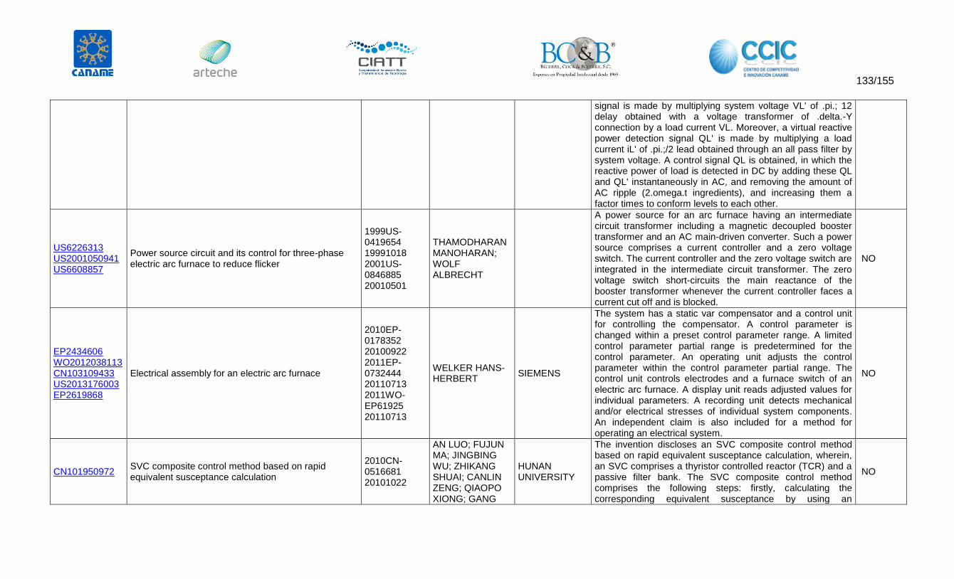
133/155
signal is made by multiplying system voltage VL' of .pi.; 12 delay obtained with a voltage transformer of .delta.-Y connection by a load current VL. Moreover, a virtual reactive power detection signal QL' is made by multiplying a load current iL' of .pi.;/2 lead obtained through an all pass filter by system voltage. A control signal QL is obtained, in which the reactive power of load is detected in DC by adding these QL and QL' instantaneously in AC, and removing the amount of AC ripple (2.omega.t ingredients), and increasing them a factor times to conform levels to each other.
US6226313 US2001050941 US6608857
Power source circuit and its control for three-phase electric arc furnace to reduce flicker
1999US-0419654 19991018 2001US-0846885 20010501
THAMODHARAN MANOHARAN; WOLF ALBRECHT
A power source for an arc furnace having an intermediate circuit transformer including a magnetic decoupled booster transformer and an AC main-driven converter. Such a power source comprises a current controller and a zero voltage switch. The current controller and the zero voltage switch are integrated in the intermediate circuit transformer. The zero voltage switch short-circuits the main reactance of the booster transformer whenever the current controller faces a current cut off and is blocked.
NO
EP2434606 WO2012038113 CN103109433 US2013176003 EP2619868
Electrical assembly for an electric arc furnace
2010EP-0178352 20100922 2011EP-0732444 20110713 2011WO-EP61925 20110713
WELKER HANS-HERBERT
SIEMENS
The system has a static var compensator and a control unit for controlling the compensator. A control parameter is changed within a preset control parameter range. A limited control parameter partial range is predetermined for the control parameter. An operating unit adjusts the control parameter within the control parameter partial range. The control unit controls electrodes and a furnace switch of an electric arc furnace. A display unit reads adjusted values for individual parameters. A recording unit detects mechanical and/or electrical stresses of individual system components. An independent claim is also included for a method for operating an electrical system.
NO
CN101950972 SVC composite control method based on rapid equivalent susceptance calculation
2010CN-0516681 20101022
AN LUO; FUJUN MA; JINGBING WU; ZHIKANG SHUAI; CANLIN ZENG; QIAOPO XIONG; GANG
HUNAN UNIVERSITY
The invention discloses an SVC composite control method based on rapid equivalent susceptance calculation, wherein, an SVC comprises a thyristor controlled reactor (TCR) and a passive filter bank. The SVC composite control method comprises the following steps: firstly, calculating the corresponding equivalent susceptance by using an
NO

134/155
WANG; YUNBIN SUN
equivalent susceptance computing method after detecting a voltage signal and a current signal; adding up an open-loop equivalent susceptance output value BLabc and a closed-loop PI regulator output value to obtain a total equivalent susceptance compensation value BTabc; calculating the actual input group number n of PPFs and the actual equivalent susceptance value of the TCR by a power divider according to the compensation value; and searching an Hash table bythe TCR according to the actual equivalent susceptance value to obtain a corresponding triggering angle and then triggering opening of a corresponding thyristor to send out corresponding inductive reactive current for compensating capacitive reactive power and negative-sequence current, and finally realizing complete compensation of the reactive power and the negative-sequence current of a system. The SVC composite control method effectively reduces the calculated quantity of the system and improves the response time of the system.
CN201466732 Static var compensator for steelmaking electric arc furnace
2009CN-U070704 20090420
JIANJUN GU; BAONIAN HU; KAI LI; YONGZHENG ZHENG
BAOSHAN IRON & STEEL
The utility model discloses a static var compensator for a steelmaking electric arc furnace, which consists of a thyristor controlled reactor (2) and a filter, and the thyristor controlled reactor is connected with the filter in parallel; the thyristor controlled reactor is a three-phase main circuit with the triangular connection way, and each-phase circuit consists of a thyristor (7) and a reactor which are arranged in a pair and in inverse parallel connection; and the filter is an injection-type hybrid shunt active power filter (1) comprising an active power filter (3) and a passive filter(6), the active power filter is series-connected with an inductor (4) and then connected into a primary side of an isolation transformer (5), and a secondary side of the isolation transformer is parallel-connected with a series resonance circuit consisting of a capacitor C11 and the reactor L1, then series-connected with the capacitor C12 and further parallel-connected with the passive filter to be connected into a power grid. The static var compensator can realize the comprehensive harmonic and reactive power dynamic compensation, improve the filter
NO

135/155
effect of the static var compensator and improve the stability of the device.
CN102842909 Method for controlling power electronic hybrid system 2012CN-0336074 20120912
SHUAI ZHIKANG; TU CHUNMING; PAN HONGBIN; YAO PENG; JIANG LING; DAI XIAOZONG; CHU LANG; XIAO FAN; ZHANG YANG
HUNAN UNIVERSITY
The invention discloses a method for controlling a power electronic hybrid system. The method comprises a power electronic hybrid control system comprising an active power filter and a static var compensator, wherein the static var compensator comprises a passive power filter group and a thyristor control reactor (TCR); and the active power filter, the passive power filter group and the TCR access between a power grid and loads connected with the power grid in sequence. The passive power filter and the active power filter are used jointly to perform harmonic suppression on high-voltage busbars; and the static var compensator is used to perform reactive compensation, so that delay compensation and online control are realized, control accuracy is enhanced, tracking performance is improved, electric energy loss of the power grid is reduced, and pollution of the power grid is purified.
NO
US2003098672 SE0103985 EP1318588 CN1459907 US6674267 SE523039 CN1320719 AT539476 ES2376192
A method and a device for compensation of the comsumption of reactive power by an industrial load
2001SE-0003985 20011128
WERNERSSON LENNART
ABB
An industrial load (2), preferably an electric arc furnace or a plant for rolling of metallic materials, is supplied from a three-phase (a, b, c) electric ac network (1). A device for compensation of the reactive power consumption of the load comprises a first compensation device (3) for controllable consumption of reactive power and a second compensation device (4) for generation of reactive power, both connected to the electric power network in a parallel connection with the load. The first compensation device comprises a thyristor-controlled reactor (31, 32) for each of the phases of the ac network. Control equipment (7) is supplied with measured values of sensed amplitude values for voltages and currents. The control equipment comprises means (81, 82) for forming a voltage mean value (UAV, UAV') as the mean value of the sensed amplitude values of voltage, and means (83) for forming, for each of the thyristor-controlled reactors, an amplitude deviation ([<control>]Uab, [<control>]Ubc, [<control>]Uca) as a difference of the voltage mean value and the amplitude value associated with the thyristor-
NO

136/155
controlled reactor, and means (84, 91, 92) for forming, for each of the thyristor-controlled reactors, a separate control order in dependence on the amplitude deviation for the respective thyristor-controlled reactor.
CN201966625 Dynamic reactive power compensation device 2011CN-U103970 20110411
XUEWEN LI; LIQUN ZHAO; WEI LEI; SHAOWEI YANG; LIN LIU
KUNMING ENGINEERING & RESEARCH INSTITUTE OF NONFERROUS METALLURGY
The utility model provides a dynamic reactive power compensation device, which comprises a filtering compensation capacitor bank, a thyristor controlled reactor bank and a transformer, wherein the filtering compensation capacitor bank is connected to a low-voltage bus; the transformer is connected with the low-voltage bus and a high-voltage bus respectively; and the device is characterized in that: the high-voltage bus is connected with the filtering compensation capacitor bank. Basic reactive power of an electric arc furnace can be conveniently compensated and harmonic waves can be filtered, so that only the reactive power of a fluctuation part passes through the transformer, but the reactive power of the fluctuation part has extremely small capacity under a normal condition; wide fluctuation occurs only when the electric arc furnace is subjected to short circuiting or arc breaking, so that the transformer is in a light load condition under the normal condition; thus the capacity of the transformer can be reduced by about 50 percent, investment can be effectively saved, the capacity and load rate of the transformer are relieved, the loss of the transformer is greatly reduced to below 40 percent of the loss of the original transformer, and energy conservation can be effectively realized.
NO
CN86101078 JPS61194515 CN1006583 JPH0584524 JP1877362
VOLTAGE VARIANCE SUPPRESSOR 1985JP-0035088 19850222
YAMAMURA HIDEKI; NISHIYAMA SATOSHI; EGAMI ICHIRO
NISSHIN ELECTRIC
PURPOSE: To suppress the variation of both the overvoltage and the under voltage even due to the long cycle fluctuation by controlling conduction with a thyristor ignition phase control signal obtained by adding the comparison signal between the bus voltage signal and the reference voltage signal and the thyristor steady operation signal. CONSTITUTION: When the system voltage is set at a level between the upper and lower limit set voltage levels V(sub 0) and V(sub u), the voltage VIN' given from a reference voltage circuit 6 is used directly as the reference voltage V(sub ref)
NO

137/155
and compared with the voltage output signal VIN given from a voltage detector 5. Then a command is given to an adder 17 and a pulse generator 9 to flow more amount of current to a thyristor 11 in the case of VIN>V(sub ref). Thus the control is carried out so as to satisfy VIN=VIN' (V(sub ref)). When the system current gets out of the range between the upper and lower set levels, e.g., VIN'=V(sub 0) is satisfied, the voltage V(sub 0) serves as the V(sub ref). Hereafter, an action equal to that done in the case of said VIN=V(sub 0) (V(sub ref)) and the control is carried out to satisfy VIN'=V(sub 0). These controls are performed by deciding an ignition phase angle pulse by the input signal VP of the generator 9 to perform the control of conduction of a serial reactor 10 and in the direction where the variance of the bus voltage is suppressed.
SE9602368 WO9749157 EP0847612 CN1195428 JPH11511960 US6114841 DE69704602 SE515107 CN1099744
METHOD AND DEVICE FOR COMPENSATION OF REACTIVE POWER
1996SE-0002368 19960617 1997WO-SE01005 19970609
HASLER JEAN-PHILIPPE; JOHANSSON THOMAS; AENGQUIST LENNART
ABB ABB VAESTERAAS
A device for compensation of the reactive power consumption of an industrial load, preferably an electric arc furnace or a plant for rolling of metallic materials, supplied from a three-phase (a, b, c) electric ac network, comprises a first compensation device for controllable consumption of reactive power and a second compensation device for generation of reactive power. The first compensation device comprises an inductor connected in series with a semiconductor connection controllable in dependence on a control order ( alpha ref) supplied thereto. Control equipment is supplied with measured values of voltage (Ua, Ub, Uc) and current (Ia, Ib, Ic), respectively, at the load. The control equipment comprises devices for determination of the instantaneous consumption of active and reactive power by the load, and a control device which forms the control signal to the first compensation device in dependence on the consumption of reactive power and active power by the load.
NO
CN102570481 Calculating method of inductance value of thyristor controlled reactor
2012CN-0024514 20120203
HUAJUN ZHANG
WISDRI ENGINEERING & RESEARCH INCORPORATION
The invention brings forward a calculating method of an inductance value of a thyristor controlled reactor (TCR). The method comprises the following steps that: A, on the basis of a static dynamic reactive power compensator principle of a TCR, expression of a fundamental current and all
NO

138/155
subharmonic currents of the reactor is established; B, a fundamental wave inductive reactive power compensated by the reactor is derived; C, according to different control angles, coefficients of proportions between a harmonic wave reactive power and a fundamental wave reactive power are obtained by calculation; and D, an inductance value equation is derived, an extreme value of the control angles is input, and comparison relations between data under the extreme value state are calculated, so that security of the reactor is determined. According to the above-mentioned technical scheme, according to demands of a minimum harmonic current and a maximum fundamental power, an inductance value of the reactor is calculated; therefore, the reactor can meet various control angles operation requirements, so that an occurrence of a burning down phenomenon can be avoided; and furthermore, safe and stable running of the TCR device is ensured.
AU3799885 JPS60204230 US4555659 IN161072 AU574421 CA1256490
Static VAR generator system having improved response time
1984US-0584203 19840227
GYUGYI LASZLO ABB WESTINGHOUSE ELECTRIC
A static VAR generator utilizing a multitude of reactor banks each having different computation circuits and firing angle control circuits is provided. The different computation and firing angle control circuits allows the VAR generator the flexibility of being able to change the reactor power in an A.C. network repetitively in any cycle in response to rapid changes in load demand. This is accomplished by each reactor bank having progressively longer computation times and later insertion of additional banks into the network after the first bank has responded to load demand.
NO
CN102709886 Status monitoring and overvoltage protection system of high-voltage TCR (Thyristor Controlled Reactor) thyristor valve gate set
2012CN-0190097 20120608
HONGYING WANG; PINGJIN BI; SHAOCHUN FAN; SHAOTAO JIANG; XIAOFEN LI; YUNCHENG LUO
HUBEI SANHUAN DEVELOPMENT
The invention discloses a status monitoring and overvoltage protection system of a high-voltage TCR (Thyristor Controlled Reactor) thyristor valve gate set, which comprises a main control device, a static voltage-equalizing and information acquisition module, a thyristor working status monitoring module, an AC voltage acquisition module, an overvoltage judging and signal expanding module, a forced triggering pulse string generating module, a high-level energy-acquiring and 1+1 redundant power supply, and a thyristor triggering module, wherein the static voltage-equalizing and information
NO

139/155
acquisition module is used for extracting AC voltage information and bi-directional overvoltage signals; the thyristor working status monitoring module is used for monitoring AC voltage signals of the TCR thyristor valve gate set; the AC voltage acquisition module is used for monitoring the bi-directional overvoltage information of the TCR thyristor valve gate set; the overvoltage judging and signal expanding module is used for carrying out overvoltage judgment according to the bi-directional overvoltage information; and the high-level energy-acquiring and 1+1 redundant power supply is used for controlling conduction and conduction angle of the TCR thyristor valve gate set. The status monitoring and overvoltage protection system disclosed by the invention is simple and reliable and low in cost and can be used for overvoltage protection on the high-voltage TCR thyristor valve gate set and real-time detection on the normal working status of the high-voltage TCR thyristor valve gate set.
SE0004415 WO200245235 AU1529002 SE517777 EP1344295 US2004052015 CN1488185 US6984962 CN100440678
A DEVICE AND A METHOD FOR VOLTAGE CONTROL IN AN ELECTRIC TRANSMISSION NETWORK
2000SE-0004415 20001130 2001WO-SE02557 20011120
AENGQUIST LENNART; THORVALDSSON BJOERN
ABB
A device for control of a compensator connected to a polyphase electric transmission network for reactive electric power in dependence on a voltage sensed in the transmission network. A voltage controller, in dependence on the difference of a reference value for the voltage and its sensed value, forms a reference value for a reactive power flow through the compensator. A transformation element represents the sensed voltage as a voltage vector in a rotating two-phase system of coordinates and forms a compensation signal in dependence on a sensed change of the angular position of the voltage vector in the two-phase system of coordinates. A summation element forms the reference value for reactive power flow through the compensator in dependence on the compensation signal.
NO
EP2445076 WO2012052424 CA2814978 MX2013004259 CN103201926
Electricity supply system for a non-linear load which varies over time
2010EP-0187992 20101019 2011EP-0773713
WONG KWOK TUNG
SIEMENS
The device has a multilevel converter (5) with a common neutral point (7) connected with a neutral point (12) of a filter circuit (8) and a neutral point (15) of a zigzag winding (14) attached to phases (3) of a current system (2). The common point is connected with the phases over the circuit and the
SI

140/155
EP2617114 US2013207623 IN0982/KOLNP/2013
20111018 2011WO-EP68166 20111018
winding such that a low impedance connection of the common point with the phases is provided relative to a null current of the current system and a high impedance connection of the common point with the phases is provided relative to positive sequence of the current system.
CAPACITOR CON UN INTERRUPTOR POR TIRISTOR (TSC)
WO8100648 GB2057796 SE8102685 DE3049822
CURRENT DAMPING ARRANGEMENTS
1979GB-0029730 19790828 1980WO-GB00132 19800827
THANAWALA H
ASS ELECTRIC INDUSTRY ASSOCIATED ELECTRICAL INDUSTRIES
A damping arrangement for thyristor switched capacitors in reactive power compensation systems. Large inrush currents are possible where capacitors are re-connected after a time of disconnection. The invention consists of incorporating in series with the thyristor switching bank a large damping resistor bypassed by thyristors which may in fact be a series part of the main switching bank. The bypass is opened prior to closing the main thyristors and closed a short time after thus encouraging decay of transients. The re-closing of the bypass may be done in stages (sections of the damping resistor) or progressively in successive cycles.
NO
CN2533603 Electric power filtering and dynamic reactive compensation device
2002CN-U218345 20020113
YANG YIMIN; FENG SHENRONG
FENG SHENRONG
The utility model discloses a power filtering and dynamic reactive compensation device and consists of a current transformer, a voltage transformer, a controller, a filter, a thyristor switching reactor group and a reducing transformer, wherein, the filter is formed by the parallel connection of a plurality of filtering branch circuits which are formed by the serial connection of a filtering reactor and a filtering capacitor; the thyristor switching reactor group is formed by the parallel connection of a plurality of branch circuits of thyristor reactors formed by the serial connection of a reactor and a thyristor alternative current switch formed by the reverse parallel connection of two thyristors; the thyristor switching reactor group is in parallel connection with the filter through the reducing transformer; a control pole of the thyristor is connected with the controller; the current transformer and the voltage transformer are connected between a power net bus and the controller. The power filtering and dynamic reactive compensation device of the utility model has the advantages of good filtering effect, being able to avoid the economic loss of railway and power
NO

141/155
departments and eliminating the harms or disturbances caused to power users by high harmonics and voltage fluctuation and is suitable for electrified railways and other power distribution networks with harmonics and fluctuating wavy load.
WO2010099831 CA2753992 AU2009341480 MX2011009058 US2011316493 EP2404356 CN102334257 US8314596 IN7148/CHENP/2011
POLY-PHASE REACTIVE POWER COMPENSATOR 2009WO-EP52683 20090306
THORVALDSSON BJOERN; HALONEN MIKAEL
ABB TECHNOLOGY
The invention relates to a poly-phase reactive power compensator 1 comprising for each phase a, b, c a reactive power means 3a, 3b, 3c; 2a, 2b, 2c. The poly-phase reactive power compensator 1 further comprises means 21, 22, 23; 31, 32, 33 for transferring susceptance between the phases a, b, c. The invention also provides a control device for controlling the poly-phase reactive power compensator 1.
SI
CN101071946 Large-capacity dynamic reactive power compensating system
2007CN-0022178 20070518
YIN YUEXIN
NANJING XINYA ENERGY AUTOMATION
The invention is a large-capacity dynamic reactive compensating system, belonging to the field of power electronics technique, comprising coupling transformer, and invert capacitor, and characterized in that: per phase reactive dynamic compensating circuit is composed of four IGBT tubes Q1, Q2, Q3 and Q4 and two diodes D1 and D2, where the IGBT tubes Q1, Q2, Q3 and Q4 are interconnected in series and the diodes D1 and D2 are interconnected in series, too, the anode of the diode D2 is connected with series node of the Q3 and Q4 and the cathode of the diode D1 is connected with series node of the Q1 and Q2, the series node of the Q2 and Q3 acts as the output of this phase circuit to connect with the coupling transformer, and the series node of the diodes D1 and D2 acts as common ground end to connect with zero line. And it has good compensating effect and radically solves the problem of dynamic compensation of large capacity load.
NO
US2010109616 System and method for reactive power compensation and flicker management
2008US-P198278 20081104 2009US-0590178
LI HUAQIANG; KANG YONG; LIN XINCHUN; LIU XIAOHU
EATON
A Thyristor Switched Capacitor (TSC) system connected to three sets of diodes and thyristors connected in parallel with the diodes being in an anti-parallel configuration, three capacitors connected in series with the diodes and thyristors, and three surge current controlling reactors that control the
NO

142/155
20091104 transient time to improve power quality in the grid.
Título Autores Institución Publicación Año Resumen Link al pdf
Electrical aging tests on epoxy
insulators in GIS Diessner, A.; Luxa, G.; Neyer, W.
Siemens AG,
Berlin, West
Germany
Electrical
Insulation, IEEE
Transactions
on
1989
Due to the relatively small insulator dimensions in gas-
insulated switchgear (GIS), the electrical stressing is high by
comparison to that of insulators for conventional switchgear.
Aging tests on a large number of full-sized insulators in several
vessels in an outdoor test station have been carried out to
determine the stress limits. The tests, with voltages of several
hundred kilovolts, last for several years. The aim is to work out
conditions (by extrapolation) for a trouble-free switchgear
operating life of at least 50 years. The most important test
objects are postinsulators weighing 2 kg each. It has been
confirmed that partial discharges have a major effect on the
failure probability. The life curve obtained from the test results
of six batches of partial-discharge-free insulators is compared
with the required reliability data
http://ieeexplore.ieee.org/stamp/stamp.jsp?arnumber=90286
Determination of gases and gas
pressure in GIS spacer voids Braun, J-M; Groeger, J.H.
Ontario Hydro
Res., Toronto,
Ont., Canada
Electrical
Insulation and
Dielectric
Phenomena,
1989. Annual
Report.,
Conference
on
1989
The gas contents of voids found in commercial epoxy
spacers and laboratory samples are investigated as part of a
broader investigation into the aging characteristics of GIS
(gas-insulated switchgear) spacers. Gas chromatography
techniques were successful in identifying permanent gases
and organic vapors in epoxy spacers. Simple crushing and,
where practical, drilling were used to release the gaseous
effluents. Analyses performed on production epoxy spacers
yielded predominantly nitrogen and oxygen with, in much
smaller concentrations, uncured residues and curing by-
products similar to those dissolved in the epoxy mass. Given
the high temperatures at the time of formation of the
cavities, diffusion processes in the liquid-like mass will
establish rapid equilibrium between the voids and the
surrounding epoxy mass. Control of the gas and pressure
content in epoxy cavities is similarly difficult to achieve where
desired because of diffusion effects in the curing mass. While
oxygen depletion can be readily ascribed to reaction with
the uncured epoxy, the presence of excess nitrogen cannot
yet be explained satisfactorily
http://ieeexplore.ieee.org/stamp/stamp.jsp?arnumber=69531

143/155
Studies of epoxy spacers
subjected to internal and
external partial discharge and
SF<sub>6</sub> byproducts
Braun, J-M; Chu, F. Y.; Tyman, A.
Ontario Hydro
Res. Div.,
Toronto, Ont.,
Canada
Conduction
and
Breakdown in
Solid
Dielectrics,
1989.,
Proceedings
of the 3rd
International
Conference
on
1989
The early phases of the internal and external spacer surface
degradation process were characterized using electrical
and chemical techniques in order to develop a better
understanding of the long-term aging mechanisms. Reaction
of nitrogen gas in a discharge cavity with the epoxy void
wall was readily detected by ESCA (electron spectroscopy
for chemical analysis), and the technique could find
application in determining the void size below which no
damage occurs. A similarly substantial modification of
spacer surface properties could be brought about by
exposure to localized corona discharges, associated with
material transfer from the electrode and leading ultimately
to the formation of tracklike paths on the epoxy surface. The
results are of interest in connection with the electrical treeing
of GIS (gas-insulated switchgear) spacers
http://ieeexplore.ieee.org/stamp/stamp.jsp?arnumber=69217
Surface discharge switch
design: the critical factor Engel, T.G.; Kristiansen, M.; Baker, M.; Hatfield, L.
Texas Tech.
Univ.,
Lubbock, TX,
USA
Power
Modulator
Symposium,
1990., IEEE
Conference
Record of the
1990
Nineteenth
1990
The authors report which dielectric properties are critical to
designing a long-life surface discharge switch (SDS). Theory is
correlated with experiment by evaluating the performance
of a large group of polymeric and ceramic dielectrics. These
dielectrics were tested in a single-channel, self-commutating
SDS operating at ~35 kV and ~ 300 kA (oscillatory discharge)
with a pulse length of ~20 μs (1/4 period ~2 μs). The
performance of a dielectric is characterized by its shot-to-
shot breakdown voltage and by its mass erosion.
Theoretically, the voltage holdoff degradation resistance
and the arc melting/erosion resistance of a dielectric can be
qualitatively predicted from its `formativity' and its
`impulsivity', respectively. The formativity and impulsivity are
figures of merit calculated from the known thermophysical
properties of the dielectric. The effects produced in dielectric
performance by choice of electrode material (e.g.,
molybdenum, graphite, and copper-tungsten) and
discharge repetition rate are also discussed
http://ieeexplore.ieee.org/stamp/stamp.jsp?arnumber=201000
Surface flashover and solid
polymeric insulation in
SF<sub>6</sub> gas
Rickman, J.; Milne, D.
NEI Int. Res. &
Dev. Ltd.,
Newcastle, UK
Charging and
Tracking of
Insulators in
Gaseous and
Vacuum
Environments,
IEE Colloquium
on
1990
The application of synthetic resins as dielectric materials in
the design and construction of switchgear originated early in
this century. Since then a very large and ever widening
number of materials and their compounds have been
developed. The authors consider flashover tests which have
been carried out to compare the performance of various
polymeric formulations and relate these results to the
chemical structure of the resin tested. There are many factors
which influence surface flashover performance and these
are outlined by the authors
http://ieeexplore.ieee.org/stamp/stamp.jsp?arnumber=190081

144/155
Proceedings of the 1991 IEEE
Power Engineering Society
Transmission and Distribution
Conference (Cat.
No.91CH3070-0)
Transmission
and
Distribution
Conference,
1991.,
Proceedings
of the 1991
IEEE Power
Engineering
Society
1991
The following topics are dealt with: cleaning solvents and
cable pulling; cable testing; cables and accessories; high
voltage cables; cable performance; moisture impervious
and shielded cable; new and specialized products; system
dynamic performance; system planning and demand-side
management; power system instrumentation and
measurement; power system relaying; surge protective
devices; substations; switchgear; transformers; distribution
automation and design; distribution reliability; EMF from
power lines; DC transmission; towers, poles, and conductors;
transmission and distribution design and safety; transient and
steady state analysis of power systems; shunt and series VAR
compensation in power systems; and six-phase power
transmission systems
http://ieeexplore.ieee.org/stamp/stamp.jsp?arnumber=169475
Endurance estimation of epoxy
resin systems under synergistic
environment of high relative
humidity and electrical stress
Udayakumar, K.; Panneerselvam, M. A.; Dharmalingam, K.
Coll. of Eng.,
Anna Univ.,
Madras, India
Properties and
Applications
of Dielectric
Materials,
1991.,
Proceedings
of the 3rd
International
Conference
on
1991
The authors report on an experimental investigation
undertaken to quantify the effect of high humidity on the
performance of epoxy resin insulations. The data obtained
from the investigations have been used to calculate a new
index called the cumulative characteristic factor, which
uniquely grades the material and insulation systems exposed
to permanently elevated humidity conditions. To assess the
long-term behavior, endurance tests were also conducted
with a newly designed environment cycle representing
tropical climatic conditions. Based on the accelerated test
data, a system model has been developed for predicting
the insulation life. To validate the laboratory aging tests, a 11
kV current transformer was installed in a highly humid region
in Madras City, India. The place of installation was a
switchgear plant for air conditioning purposes. From the
experimental investigations and model developed it was
concluded that in the presence of permanently elevated
humidity conditions bisphenol epoxy resins are susceptible to
severe surface degradation within 2 to 3 years of installation
http://ieeexplore.ieee.org/stamp/stamp.jsp?arnumber=172164

145/155
PD scaling relationships in GIS
insulators: theory and
experimental verification
Braun, J-M; Fujimoto, N.; Dirven, R.; Teng, M.; Addis, G.
Res. Div.,
Ontario Hydro,
Toronto, Ont.,
Canada
Dielectric
Materials,
Measurements
and
Applications,
1992., Sixth
International
Conference
on
1992
Partial discharge (PD) testing is commonly used as a quality
control measure for epoxy insulators in gas-insulated
switchgear (GIS). Occasional inservice failures have
indicated that improvements to the technology should be
considered. Recent theoretical developments have
provided a means of assessing the detectability of partial
discharges in such insulators. The theory also provides a
model which can be used to relate the characteristics of
voids within insulators with the measured signal and the
inception/extinction voltages. The authors describe
measurements which provide the experimental evidence in
support of the theory. Application of the theory results in
more stringent PD acceptance criteria for higher voltage
class insulators
http://ieeexplore.ieee.org/stamp/stamp.jsp?arnumber=186908
Surface flashover sustained by
electrostatic surface charge on
epoxy resin insulator in
SF<sub>6</sub> [GIS insulators]
Wang, C. X.; Wilson, A.; Watts, M. W.
National Grid
Co.,
Leatherhead,
UK
Dielectric
Materials,
Measurements
and
Applications,
1992., Sixth
International
Conference
on
1992
It has been confirmed that sufficiently high electrostatic
surface charge density can sustain surface flashover when
the stored surface energy released can cause further
ionisation and establish a chain reaction. Therefore, in
addition to the widely reported results that surface charges
can aggravate the triple junction field enhancement under
certain conditions, it is now clear that once triggered,
surface flashover can self-propagate a long distance away
from the initiation sites, resulting in unexpected and
erratically low flashover voltages. The proposed self-
sustained surface flashover criterion has been tested to
apply for different geometries and at various SF<sub>6</sub>
pressures. The criterion simply states that the electrostatic
surface energy should be sufficient for renewed ionisation
activities
http://ieeexplore.ieee.org/stamp/stamp.jsp?arnumber=186912
Space charge induced field
variation on epoxy spacers
under AC stresses in
SF<sub>6</sub> [GIS]
Jing, T.; Morshuis, P. H F
Delft Univ. of
Technol.,
Netherlands
Dielectric
Materials,
Measurements
and
Applications,
1992., Sixth
International
Conference
on
1992
Large scale cylindrical spacers of commercial epoxy resin
were used to have measured the charge accumulations
under AC stresses. Using a finite-element program, the field
variation due to the surface charges was calculated, and
the influence of them on the dielectric performance was
then discussed
http://ieeexplore.ieee.org/stamp/stamp.jsp?arnumber=186911

146/155
Investigation of the effect of
repetitive voltage surges on
epoxy insulation
Stone, G.C.; Van Heeswijk, R. G.; Bartnikas, R.
Ontario Hydro,
Toronto, Ont.,
Canada
Energy
Conversion,
IEEE
Transactions
on
1992
The aging of epoxy electrical insulation by unipolar,
repetitive voltage surges has been investigated to determine
whether such surges can precipitate premature failure of
high-voltage motor windings and gas insulated switchgear
spacers. A full factorial statistical test was devised and
performed on 180 pure epoxy insulation specimens to
examine the effect of voltage magnitude, polarity, and
surge repetition rate on the life of unfilled epoxy specimens
containing a needle-plane electrode geometry. All factors
and interactions were determined to have a significant
effect on the life, and life prediction equations were
estimated. Increasing the voltage magnitude or repetition
rate, decreased or increased the life, respectively. Aging
was found to occur at as low a stress as 2 MV/cm. Gradual
aging of the epoxy does occur under repetitive voltage
surges. Based on a realistic number of surges with typical
voltage amplitudes which can normally occur from vacuum
switchgear during service, gradual deterioration of the
epoxy turn insulation in motor stator windings is possible in
some situations. Situations where surge aging may occur are
identified
http://ieeexplore.ieee.org/stamp/stamp.jsp?arnumber=182659
A multistress test procedure for
qualification of composite
insulation materials in GIS
Kutil, A.; Frohlich, K.
Inst. of
Switchgear-
and High
Voltage
Technol.,
Tech. Univ.
Wien, Austria
Electrical
Insulation,
1994.,
Conference
Record of the
1994 IEEE
International
Symposium on
1994
A multistress test procedure for composite polymer insulation
materials as they are used in gas insulated systems (GIS) is
introduced. Tube materials are dielectrically and
mechanically stressed simultaneously. In a power frequency
ac field up to 120 kV/cm partial discharge (PD) patterns are
recorded by means of phase resolving and statistical
evaluation of PD impulses. First results show a significant
dependence of the PD activity on mechanical stress
conditions. Also two distinctive modes of PD impulse levels
were observed which seem to be related to the interface
between fibres and matrix. A qualitative assessment of
different materials concerning their aging behaviour seems
to be possible, however. For quantification a comparison
with endurance tests is necessary and thus planned in the
near future
http://ieeexplore.ieee.org/stamp/stamp.jsp?arnumber=401468

147/155
Early stages of discharge
development on insulating
spacers in gases-a
photographic study
Li, S. Y.; Theophilus, G. D.; Srivastava, K.D.
British
Columbia
Univ.,
Vancouver,
BC, Canada
Conduction
and
Breakdown in
Solid
Dielectrics,
1995. ICSD'95.,
Proceedings
of the 1995
IEEE 5th
International
Conference
on
1995
In gas insulated substations (GIS) spacers are subjected to a
large number of transient overvoltages and the transients
associated with switching operations have very small rise-
time (≈10 nanoseconds). An understanding of the early
stages of discharge development should be useful in the
design of GIS insulation system. As a part of this investigation,
dedicated high speed streak photography techniques have
been developed to study pre-discharge phenomena on
spacers made from polytetrafluoroethylene (PTFE), acrylic
and nylon. Since the discharge path may not always follow
along the electrode axis, thus making streak photographic
records difficult to interpret, it was decided to make a very
shallow (0.5 mm) and narrow (1 mm) grove along the spacer
axis. The arc was observed to propagate along the grove
consistently. Although the breakdown voltages for different
spacer materials varied significantly, the lowest flashover
voltage being for PTFE spacers, the temporal development
of the discharge on different materials was substantially the
same in all cases. However, the flashover voltage with a
spacer was lower than that for a plain air gap. In the present
paper results of additional experiments in nitrogen (N
<sub>2</sub>) and sulphur hexafluoride (SF<sub>6</sub>) at
different ambient pressures are described and discussed
http://ieeexplore.ieee.org/stamp/stamp.jsp?arnumber=523009
Insulator charging in
SF<sub>6</sub> produced by
impulse voltage
Vasconcelos, F.H.; Cornick, Keith J.
Dept. de
Engenharia
Eletrica, Univ.
Federal de
Minas Gerais,
Belo
Horizonte,
Brazil
Electrical
Insulation and
Dielectric
Phenomena,
1996., IEEE
1996 Annual
Report of the
Conference
on
1996
This work is concerned with the study of the charging process
on insulators. The charges were produced by discharges
inside a test-cell containing SF<sub>6</sub>. The discharges
were due to impulse voltage applied to a point-plane
arrangement with the dielectric covering the flat electrode.
The charging current was measured along with the impulse
voltage. The surface charge deposited on the dielectric was
scanned using an electrostatic probe. The results presented
are concerned with the previous state of the samples (in
terms of charging) associated with change in polarity and in
magnitude of the applied voltage
http://ieeexplore.ieee.org/stamp/stamp.jsp?arnumber=564645

148/155
Improvement of the heat
resistance of epoxy casting resin
for insulating spacers
Ichikawa, I.; Goto, K.; Takei, M.; Nakano, T.; Kanazashi, Y.
Power & Ind.
Syst. R&D
Center,
Toshiba Corp.,
Japan
Electrical
Insulating
Materials,
1998.
Proceedings
of 1998
International
Symposium on
1998
New research has succeeded in producing more compact
insulating spacers for gas insulated switchgear (GIS) by
increasing the heat resistance (from 105°C to 115°C) of
casting resin and by increasing the heat resistance of the
interface bond between metal and resin. The newly
developed resin is composed, like conventional types, of
epoxy resin blended with alumina filler. In the new
compositions, both increased thermal resistance and
favorable mechanical properties are achieved by reducing
shrinkage during curing and the viscosity of the matrix resin,
and by increasing the content of alumina filler. The creep
rupture characteristics of the newly developed resin at
115°C equal those of conventional resin at 105°C
http://ieeexplore.ieee.org/stamp/stamp.jsp?arnumber=741740
Characterization of epoxy resin
surfaces exposed to partial
discharges in SF<sub>6</sub>
and N<sub>2</sub>-
SF<sub>6</sub> mixtures
Paun, I.; Frechette, M.F.; Wertheimer, M.R.; Larocque, R.Y.
IREQ, Hydro-
Quebec,
Varennes,
Que., Canada
Electrical
Insulation and
Dielectric
Phenomena,
1998. Annual
Report.
Conference
on
1998
In order to improve our understanding of surface
degradation of epoxy resin used in high-voltage gas-
insulated systems (GIS), discharge-induced microstructural,
morphological, and compositional changes have been
investigated using Atomic Force Microscopy (AFM) and X-ray
Photoelectron Spectroscopy (XPS). The AFM technique
enables direct observation of any possible relationship that
may exist between electrical aging and structural changes
on polymer surfaces. Samples of epoxy resin aged under the
effects of partial discharges (PD) were studied with the high-
resolution AFM technique to explore their surface
topography. PD (corona) were produced in SF<sub>6</sub>
and in nitrogen with 1% of SF<sub>6</sub> in a plane-point-
plane electrode configuration at 800 Torr, and these
discharges were made to interact with virgin epoxy resin
samples. As expected, the resin surfaces exposed to PD in
pure SF<sub>6</sub> were found to be more readily
modified than those exposed to discharges in the gas
mixture, because of the higher concentration of reactive
fragments resulting in the former case. Surface
homogenisation and/or enhancement of nanometric
surface “nodules― could be observed with increasing
total surface energy deposited (“dose―). At the same
time, XPS was carried out on the same samples, the results of
which confirmed the dominating role of reactive neutrals;
when pure SF<sub>6</sub> was used, results indicated that
surface changes were due mainly to the effects of fluorine-
containing species
http://ieeexplore.ieee.org/stamp/stamp.jsp?arnumber=732995

149/155
Evaluation of contamination
resistance of GFR epoxy rods for
indoor application by means of
a salt fog test
Ross, R.; Schmuck, F.; Megens, M. G M
KEMA,
Arnhem,
Netherlands
Conduction
and
Breakdown in
Solid
Dielectrics,
1998. ICSD '98.
Proceedings
of the 1998
IEEE 6th
International
Conference
on
1998
GFR (Glass Fibre Reinforced) epoxy insulators are very useful
where both mechanical and electrical stress are to be
endured. Outdoor applications are e.g. suspension insulators
in overhead lines and hollow insulators for cable terminations
and bushings. Indoor applications can be found in switch
gear in the form of support insulators or pull rods. The present
paper focuses on indoor applications in particular. Discussed
are: the equipment and possible environmental impact, the
kind of degradation to be expected, principles of fog tests,
the application of fog tests to rank materials and finally a
discussion of the results
http://ieeexplore.ieee.org/stamp/stamp.jsp?arnumber=709315
On the use of dielectric
coatings in particle-
contaminated gas insulated
switchgear
Morcos, M.M.; Zhang, S.; Holmberg, M.; Srivastava, K.D.
Kansas State
Univ.,
Manhattan,
KS, USA
Solid
Dielectrics,
2001. ICSD '01.
Proceedings
of the 2001
IEEE 7th
International
Conference
on
2001
Electrical insulation performance of GIS/GITL systems is
adversely affected by metallic particle contaminants. These
particles may be free to move in the electric field, or may be
fixed on the conductors, thus enhancing local electric fields.
Dielectric coatings applied to the inside surface of the outer
enclosure of a coaxial GIS/GITL system improve the insulation
performance. Coating reduces the degree of surface
roughness on conductors, thus decreasing the high local
electric fields. The electric field necessary to lift a particle
resting on the bottom of a GIS/GITL enclosure is much
increased due to the coating. In a horizontal coaxial system
with particles resting on the inside surface of the enclosure,
the motion of such particles is random in nature. Particles in
practical systems can exist in a wide variety of shapes and
sizes, and of materials of different densities. In this paper, only
aluminum wire particles of 0.27 mm diameter in a 110
mm/304 mm diameter coaxial electrode system under 50 Hz
AC applied voltage are considered. In the theoretical
calculation, wire particles were represented by a cylinder
hemispherically terminated at both ends
http://ieeexplore.ieee.org/stamp/stamp.jsp?arnumber=955510

150/155
The electrical performance of
air or nitrogen gas with solid
insulation and the application
for switchgears
Mizuno, T.; Morita, K.; Kurata, Y.; Miyagawa, H.
Core Technol.
Res. Dept.,
Meidensha
Corp., Tokyo,
Japan
Transmission
and
Distribution
Conference
and Exhibition
2002: Asia
Pacific.
IEEE/PES
2002
The electrical performance of air or N<sub>2</sub> insulated
system could be improved by composite gas/polymer
insulation. Extensive investigations on composite insulated
system have shown the possibility of substitution for
SF<sub>6</sub> insulated system. We applied the covered
hemisphere-rod/plate electrode for studying the effect of
composite insulated system for an application of
switchgears. It was found in our studies that this system
improved the dielectric strength up to maximum 1.5 times
higher than that of air or N<sub>2</sub> insulated system at
0.2 MPaåáG, using a liquid rubber as a cover of the rod.
However, a liquid rubber cannot be applied in air as an
insulated gas where oxidant degradation occurs in constant
heat. On the other hand, it is presumably possible to utilize a
liquid rubber in N<sub>2</sub> where oxidant degradation
does not occur, since the examination of heat degradation
showed that its electric characteristics was maintained. This
paper presents the improvement effect for a composite
insulated system with a liquid rubber, compared with some
fundamental results about air or N<sub>2</sub> gas
insulation performance.
http://ieeexplore.ieee.org/stamp/stamp.jsp?arnumber=1177728
Thermal interruption capability
of carbon dioxide in a puffer-
type circuit breaker utilizing
polymer ablation
Uchii, T.; Shinkai, T.; Suzuki, K. Toshiba Corp.,
Tokyo, Japan
Transmission
and
Distribution
Conference
and Exhibition
2002: Asia
Pacific.
IEEE/PES
2002
When adopting an alternative arc quenching gas to
SF<sub>6</sub> which has recently been recognized as a
greenhouse gas, it is easily anticipated that the thermal
interruption capability of the GCB will be lower than that in
using SF<sub>6</sub>. In this paper, adopting
CO<sub>2</sub> as an alternative gas, the means utilizing
ablation phenomenon of polymer materials as one of the
breakthrough technologies compensating the drop in the
interruption performance will be proposed and tested by a
full-scaled GCB model. As a result, a change in the blasting
pressure characteristics was observed, and also the peak
pressure for the ablation application model was about 1.3
times higher than that of the conventional model without the
ablation element. Furthermore, even if compared at the
same blasting pressure condition at current zero, the thermal
interruption capability of the CO<sub>2</sub> gas in the
ablation application model was presumed to be improved
with comparison to the conventional model without the
ablation element. The thermal interruption capability of the
CO<sub>2</sub> gas in the ablation application model
could be estimated to be about 50 % of that of
SF<sub>6</sub> gas in the conventional model in this
interrupting test.
http://ieeexplore.ieee.org/stamp/stamp.jsp?arnumber=1177719

151/155
SF<sub>6</sub> reclaimer from
SF<sub>6</sub>/N<sub>2</sub>
mixtures by gas separation with
molecular sieving effect
Toyoda, M.; Murase, H.; Imai, T.; Naotsuka, H.; Kobayashi, A.;
Takano, K.; Ohkuma, K.
High Voltage
Switchgear
Dept., TM T&D
Corp.,
Kawasaki,
Japan
Power
Delivery, IEEE
Transactions
on
2003
This paper discusses the various methods for sulfur
hexafluoride (SF<sub>6</sub>) separation from a mixture of
low concentrations of SF<sub>6</sub> in N<sub>2</sub>
pressure swing adsorption (PSA) with a suitable kind of
synthetic zeolite, which has the expected molecular sieving
effect. This molecular sieving effect, derived from molecular
size difference between SF<sub>6</sub> and
N<sub>2</sub>, is confirmed by the difference between two
equivalent volumes filled with SF<sub>6</sub> and
N<sub>2</sub>. Prototype equipment of SF<sub>6</sub>
separation and liquefaction, that is about 1 m cube in size
and 150 kg in weight, has been assembled and tested. The
ability of gas mixture handling is 13 l/min on average, and
the SF<sub>6</sub> content is reduced to 0.0%
(undetectable level) in separated N<sub>2</sub> to exhaust
into the atmosphere.
http://ieeexplore.ieee.org/stamp/stamp.jsp?arnumber=1193862
Insulation technology for
medium voltage solid insulated
switchgear
Shioiri, T.; Sato, J.; Ozaki, T.; Sakaguchi, O.; Kamikawaji, T.;
Miyagawa, M.; Homma, M.; Suzuki, K.
Toshiba Corp.,
Tokyo, Japan
Electrical
Insulation and
Dielectric
Phenomena,
2003. Annual
Report.
Conference
on
2003
The authors have developed solid insulated switchgear that
does not use SF<sub>6</sub> gas at all as an insulating
medium. This paper describes the insulating material
technology, diagnostic technology for partial discharge,
insulation technology of the vacuum disconnecting switch
and aerial composite insulation technology which are
applied to this solid insulated switchgear. A new epoxy resin,
which was dispersedly configured with spherical silica and
rubber particles, was developed. The insulation performance
of this resin is 50% higher compared with filling of alumina.
Utilizing the features of the solid insulated switchgear, a
diagnostic technology for partial discharge employing an
acoustic emission (AE) sensor was developed. A vacuum
disconnecting switch with high insulation reliability was
developed applying Weibull distribution to dielectric
breakdown in a vacuum. The insulated parts of insulating
rods of circuit-breakers and disconnecting switches were
miniaturized through composite insulation.
http://ieeexplore.ieee.org/stamp/stamp.jsp?arnumber=1254863

152/155
Feasibility study on FGM
(functionally graded materials)
application for gas insulated
equipment [solid insulators]
Shumiya, H.; Kato, K.; Okubo, H. Nagoya Univ.,
Japan
Electrical
Insulation and
Dielectric
Phenomena,
2004. CEIDP
'04. 2004
Annual Report
Conference
on
2004
For size reduction of electric power equipment, the electric
field stress around solid insulators is to be increased and must
be carefully considered. This concern may be solved by the
application of FGM (functionally graded materials). We
investigated an application feasibility of FGM, from both an
experimental approach and numerical simulation, and the
fabrication technique for gas insulated equipment. Firstly, we
investigated the fabrication techniques for the continuously
graded permittivity distribution with an arbitrary direction and
gradings. As a result, we established fabrication techniques
for the grading of permittivity distribution in a higher or lower
direction by centrifugal force application. Next, we
fabricated a truncated cone FGM spacer, and carried out
dielectric breakdown experiments under lightning impulse
voltage application. Finally, we could confirm the significant
effect of FGM application for gas insulated equipment.
http://ieeexplore.ieee.org/stamp/stamp.jsp?arnumber=1364262
Polyurethane foam application
for high voltage insulation Karady, G.G.; Argin, M.; Rahmatian, F.; Rose, A.H.
Arizona State
Univ., Tempe,
AZ, USA
Electrical
Insulation and
Dielectric
Phenomena,
2004. CEIDP
'04. 2004
Annual Report
Conference
on
2004
In recent years, the improvement in optical technology has
increased the use of optical instrument transformers (OIT).
The active parts of many OITs are placed in SF<sub>6</sub>
or N<sub>2</sub> filled insulating structures. The challenge
with using these insulating gases initiated the replacement of
them with polyurethane foam, which is frequently used in
low-voltage switchgear. The insulation of an OIT was
modeled by foam filled tubes: 61.0 cm (24") long, 20.3 cm
(8") diameter and electrode gap 15.2 cm (6"), and electrode
radius 1.27 cm (0.5"). The AC and lightning impulse
breakdown voltages of these samples were determined by a
large number of tests. The repeated lightning impulse test
was conducted by using 600 impulses with a peak voltage of
120 kV. The partial discharge measurements were also
investigated.
http://ieeexplore.ieee.org/stamp/stamp.jsp?arnumber=1364303

153/155
Special Requirements on Gas-
Insulated, Metal-Oxide Surge
Arresters
Gohler, R.; Klingbeil, L.
Siemens Surge
Arresters,
Berlin
Power System
Technology,
2006.
PowerCon
2006.
International
Conference
on
2006
Equipment in high voltage power systems can be protected
effectively by metal oxide surge arresters. Basically two
different types of surge arresters are used: surge arresters with
air insulation using porcelain or polymeric housings (AIS surge
arresters) and surge arresters with SF<sub>6</sub>-insulation
using a metallic housing (GIS surge arresters). The probability
of a failure of a GIS surge arrester shall be considerably less
than for an air insulated surge arrester. Failures of GIS
equipment always will result in major outages and costly
corrective maintenance. Potential sources of surge arrester
failures are the metal oxide (MO) resistor, insulating parts as
fiber reinforced (FRP) rods and partitions and the metal
enclosure. MO resistors are not allowed to show any aging
and must have a high energy discharge capability. The FRP-
rods must be free of partial discharges and must withstand
high electrical strength. The metal enclosure must be made
of high quality material as well as the manufacturing process
shall be of high standard including sufficient testing and final
certification. Required routine testing on the completely
assembled surge arrester does not suffice rather all parts
used must be routine tested in a proper way to avoid failing
within the life time of more than 30 years. In case of a failure
caused by overloading the destruction must be limited to the
surge arrester.
http://ieeexplore.ieee.org/stamp/stamp.jsp?arnumber=4115883
Investigation using atomic
spectroscopy for the analysis of
arc discharges in switchgear
operating with polymeric
replacements for SF<inf>6</inf>
Brookes, R. J.; Looe, H. M.; Spencer, J.W.
Dept. of
Electr. Eng. &
Electron., Univ.
of Liverpool,
Liverpool, UK
Gas
Discharges
and Their
Applications,
2008. GD 2008.
17th
International
Conference
on
2008
It may be possible to replace SF<sub>6</sub> gas in power
switchgear by exploiting the arc quenching properties of
common polymeric materials. In this research, the complex
interactions between polymers and arc plasma have been
investigated in a realistic environment using a model circuit
breaker. The polymers studied were polyethylene and
polymethylmethacrylate, which exhibit different processes to
quench the arc involving energy removal by melting and
secondary reactions respectively.
http://ieeexplore.ieee.org/stamp/stamp.jsp?arnumber=5379316

154/155
Study and diagnosis of the
power transformer bushing
insulation system
Mehta, A.K.; Sharma, R. N.; Chauhan, S.; Agnihotri, S. D.
Nat. Inst. of
Technol.,
Hamirpur,
India
Pulsed Power
Conference
(PPC), 2011
IEEE
2011
Bushings are a critical component in electricity
transportation. They are used in substation buildings,
transformers, locomotives, and switchgear. Bushings cause
more than 15% of transformer failures. The main purpose of a
bushing is to transfer load currents in and out of metal
(grounded) enclosures at system voltages. The insulation
system breaks down, causes bushing failure results in
catastrophic event such as tank rupture, violent explosion of
the bushing and fire. Clearly, the risk and likelihood of
collateral and personnel damage is a major concern in such
an eventuality. This research is undertaken to study and
diagnosis of the power transformer bushing insulation system
and in-field measurement of power-factor and capacitance
using the Doble M4100 insulation analyzer. The case studies
on the different transformers showed how the trend of
moisture and dielectric properties changes with the variation
of power factor and capacitance of insulation system.
http://ieeexplore.ieee.org/stamp/stamp.jsp?arnumber=6191566
Low-Voltage Arc Simulation with
Out-Gassing Polymers Rumpler, C.; Stammberger, H.; Zacharias, A.
Fraunhofer
Inst. SCAI, St.
Augustin,
Germany
Electrical
Contacts
(Holm), 2011
IEEE 57th Holm
Conference
on
2011
Polymer walls and inserts are an important design criterion in
low-voltage switching devices. Besides their good insulation
properties they are used to influence the switching arc. An
important part of the energy dissipated in the arc is
absorbed by the walls of the arc chamber. This leads to
degradation and evaporation of the polymer and
subsequent impact on and interaction with the switching
arc. This contribution explains the enhancements of an
existing simulation model for the interaction between the
low-voltage switching arc and walls composed of polyamide
PA 66. This includes a model of plastic ablation, the influence
of the plastic vapor on the transport properties of the arc as
well as on its radiation. Calculations and comparisons with
experimental results show the applicability of the model in
arc chambers that are close to reality.
http://ieeexplore.ieee.org/stamp/stamp.jsp?arnumber=6034770

155/155
The complex permittivity of
epoxy based nanocomposites
with alumina and magnesium
oxide fillers at very low
temperatures
Andritsch, T.; Kochetov, R.; Morshuis, P. H F; Smit, J.J.
Delft Univ. of
Technol.,
Delft,
Netherlands
Electrical
Insulation and
Dielectric
Phenomena
(CEIDP), 2011
Annual Report
Conference
on
2011
Delivery of energy in areas with a large population density
and little space for high voltage equipment is an issue for
utility companies in metropolises. Gas insulated switchgear is
an alternative to conventional cable systems, enabling
higher energy densities. However, the sulfur hexafluoride
used in GIS causes environmental problems, which may not
be acceptable anymore in a society with emphasis on
sustainability. An alternative to this are superconducting
cables. High temperature superconducting cables operate
at temperatures close to the boiling point of nitrogen, which
is 77 K. Not much is known about the dielectric behavior of
insulating polymers at such temperatures. This exploratory
work investigates how the complex permittivity of epoxy
based nanocomposites changes at very low temperatures.
A broadband dielectric spectrometer was utilized to acquire
the real and imaginary part of the complex permittivity,
along with the loss factor. The base polymer for all samples is
a commercially available bisphenol-A epoxy with anhydrite
hardener. As filler material magnesium oxide powder was
used with an average particle size of 22 nm and alumina filler
with 50 nm average diameter. Both particle types were
modified with a silane coupling agent, in order to achieve a
uniform dispersion of particles in the host material. Neat
epoxy samples were used as a reference.
http://ieeexplore.ieee.org/stamp/stamp.jsp?arnumber=6232657