76771671 reverse osmosis plant
TRANSCRIPT

OSMOSIS AQE-60 (FILTERS) 09-01 0
INSTALLATION MANUAL
P.I. La Grela Bens - Gutenberg, 32
15008- La Coruña- España Teléfono: +34 981250111 Telefax: +34 981258439
AQE-60 REVERSE OSMOSIS PLANT
OSMOSIS AQE-60 (REV1) GUARANTEE 03-03
GUARANTEE
Products of GEFICO ENTERPRISE, are designed and produced according to highest international standards. Each component was tested before assembly, each plant was tested on quality and function before leaving works, in order to guarantee trouble less and efficient service to owners on site of application for many years. GEFICO ENTERPRISE trust that operator/shipyard installs the concerned plant according to its best technical standard of workmanship in an appropriate site, connecting it with qualified piping material and correct power supply. Damages occurred to GEFICO ENTERPRISE Products due to mishandling, wrong installation or negligence of operator or his delegate are excluded from any warranty. GEFICO ENTERPRISE guarantees for the period of 1 year on date plant leaving works to replace any part of the supplied plant free of charge to the owner subject the concerned applicant supplies the faulty part free of charge to the GEFICO ENTERPRISE works to be examinees, proving the part has not been damaged by force or other misuse. GEFICO ENTERPRISE reserves the right to apply technical alternations to their products according to developments of technical researches. Nevertheless GEFICO ENTERPRISE guarantees to owners to hold stock of spare parts according to international standards. The efficiency of the GEFICO ENTERPRISE Product will be guaranteed if the designed and described technical parameters are met.
GEFICO ENTERPRISE Performance Guaranty GEFICO ENTERPRISE guaranties that Electric Fresh Water Generators will meet the applicable specifications when installed, operated and maintained in accordance with our instructions.
Limited Warranty GEFICO ENTERPRISE warrants the equipment of its manufacturer to be free from defects in workmanship and materials for a period of 12 months after first start up, or 18 months after shipment, whichever occurs sooner. This warranty applies only to the original BUYER and for new and unused equipment and cannot be altered or changed by GEFICO ENTERPRISE employees or its representatives. Warranty related repairs attempted and/or executed by our authorized representative shall only apply and extended when supported in writing by GEFICO ENTERPRISE.
OSMOSIS AQE-60 (REV1) GUARANTEE 03-03
Where equipment sold hereunder is used with attachment and/or modifications which have been not recommended or approved by GEFICO ENTERPRISE in writing, such use shall not be considered normal and this Warranty shall not apply. GEFICO´s liability is limited to the replacement or repair of defective parts returned, freight prepaid by BUYER to a location to be specified by GEFICO ENTERPRISE. Repaired parts shall be returned to BUYER F.O.B. shipping point. When circumstances permit, GEFICO ENTERPRISE will invoke for the benefit of BUYER, the guarantee or warranty of GEFICO´s vendor for equipment or materials furnished, but not manufactured by GEFICO ENTERPRISE. This warranty does not extend to, and GEFICO ENTERPRISE assumes no liability for, consequential and secondary damages, or losses of any kind sustained directly or indirectly as a result of any defect in any equipment, material, or installation. GEFICO ENTERPRISE shall in no event be liable in an amount exceeding the purchase price on the equipment and transportation charges thereon. GEFICO ENTERPRISE MAKES NO WARRANTIES REGARDING EQUIPMENT MANUFACTURED BY IT OR NO OTHERS (INCLUDING WITHOUT LIMITATION, WARRANTIES AS TO MERCHANTABILITY AND FITNESS FOR A PROPOSE), EITHER EXPRESSED OR IMPLIED, EXCEPT AS PROVIDED HEREIN. THE FOREGOING SHALL CONSTITUTE THE EXCLUSIVE REMEDIES OF BUYER FOR ANY BREACH BY GEFICO ENTERPRISE OR IT WARRANTIES HEREIN. All information contained herein is based on data believed to be accurate, however, errors and/or design changes are possible. It is the BUYER´s responsibility to determine suitability for his own use of the products described. The information presented in this proposal supersedes all previous information published or presented about the Electric Fresh Water Generators. CUSTOMER: ORDER Nº: SHIP: EQUIPMENT: SERIAL NUMBER: DELIVERY DATE:
OSMOSIS AQE-60 (REV-3) 01-05
1
1-1
SECTION 0 - SAFETY NOTICE
A FIRST AID KIT SHOULD BE AVAILABLE AT ALL TIMES
REMEMBER THAT PLANT CAN BE DANGEROUS IT MAY START WITHOUT WARNING
INSTALLATION Before installation of the plant, operators should be aware of the contents of this manual. Suitable facilities, for example lifting equipment, must be provided to enable the plant to be installed safely. Mechanical installation must be completed before electrical connection; remember that the mixture of water and electricity can prove fatal. Electrical installation must only be undertaken by persons suitably experienced and qualified. Suitable arrangements must be provided for the storage of spare parts, lubricants, preservatives and chemical cleaning materials. OPERATION The control and safety system provided is necessary for the safe operation of the plant. Any device removed or adjusted to facilitate maintenance must be replaced and/or readjusted before the plant is returned to service. Operators who are likely to be in contact with the machine lubricants, or the chemicals used for protection or cleaning must be provided with, and wear, suitable protective clothing.
OSMOSIS AQE-60 (REV-3) 01-05
2
1-2
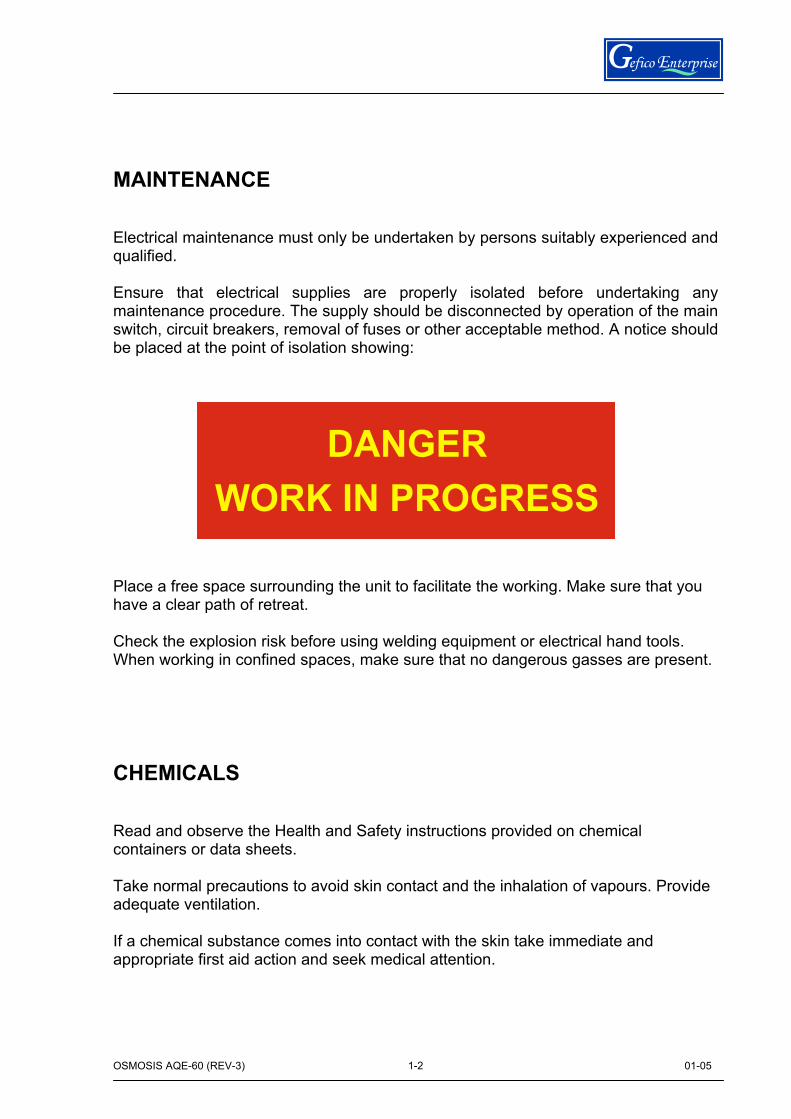
MAINTENANCE Electrical maintenance must only be undertaken by persons suitably experienced and qualified. Ensure that electrical supplies are properly isolated before undertaking any maintenance procedure. The supply should be disconnected by operation of the main switch, circuit breakers, removal of fuses or other acceptable method. A notice should be placed at the point of isolation showing: Place a free space surrounding the unit to facilitate the working. Make sure that you have a clear path of retreat. Check the explosion risk before using welding equipment or electrical hand tools. When working in confined spaces, make sure that no dangerous gasses are present. CHEMICALS Read and observe the Health and Safety instructions provided on chemical containers or data sheets. Take normal precautions to avoid skin contact and the inhalation of vapours. Provide adequate ventilation. If a chemical substance comes into contact with the skin take immediate and appropriate first aid action and seek medical attention.
OSMOSIS AQE-60 (REV-3) 01-05
3
1-3
SECTION 1
DESCRIPTION
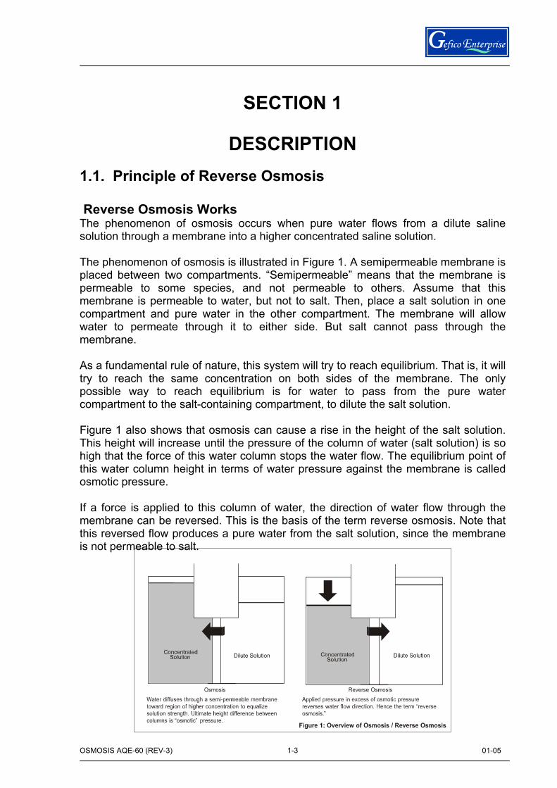
1.1. Principle of Reverse Osmosis Reverse Osmosis Works The phenomenon of osmosis occurs when pure water flows from a dilute saline solution through a membrane into a higher concentrated saline solution. The phenomenon of osmosis is illustrated in Figure 1. A semipermeable membrane is placed between two compartments. “Semipermeable” means that the membrane is permeable to some species, and not permeable to others. Assume that this membrane is permeable to water, but not to salt. Then, place a salt solution in one compartment and pure water in the other compartment. The membrane will allow water to permeate through it to either side. But salt cannot pass through the membrane. As a fundamental rule of nature, this system will try to reach equilibrium. That is, it will try to reach the same concentration on both sides of the membrane. The only possible way to reach equilibrium is for water to pass from the pure water compartment to the salt-containing compartment, to dilute the salt solution. Figure 1 also shows that osmosis can cause a rise in the height of the salt solution. This height will increase until the pressure of the column of water (salt solution) is so high that the force of this water column stops the water flow. The equilibrium point of this water column height in terms of water pressure against the membrane is called osmotic pressure. If a force is applied to this column of water, the direction of water flow through the membrane can be reversed. This is the basis of the term reverse osmosis. Note that this reversed flow produces a pure water from the salt solution, since the membrane is not permeable to salt.
OSMOSIS AQE-60 (REV-3) 01-05
4
1-4
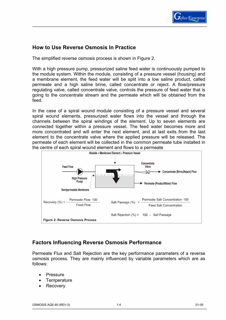
How to Use Reverse Osmosis In Practice The simplified reverse osmosis process is shown in Figure 2. With a high pressure pump, pressurized saline feed water is continuously pumped to the module system. Within the module, consisting of a pressure vessel (housing) and a membrane element, the feed water will be split into a low saline product, called permeate and a high saline brine, called concentrate or reject. A flow/pressure regulating valve, called concentrate valve, controls the pressure of feed water that is going to the concentrate stream and the permeate which will be obtained from the feed. In the case of a spiral wound module consisting of a pressure vessel and several spiral wound elements, pressurized water flows into the vessel and through the channels between the spiral windings of the element. Up to seven elements are connected together within a pressure vessel. The feed water becomes more and more concentrated and will enter the next element, and at last exits from the last element to the concentrate valve where the applied pressure will be released. The permeate of each element will be collected in the common permeate tube installed in the centre of each spiral wound element and flows to a permeate Factors Influencing Reverse Osmosis Performance Permeate Flux and Salt Rejection are the key performance parameters of a reverse osmosis process. They are mainly influenced by variable parameters which are as follows:
• Pressure • Temperature • Recovery
OSMOSIS AQE-60 (REV-3) 01-05
5
1-5
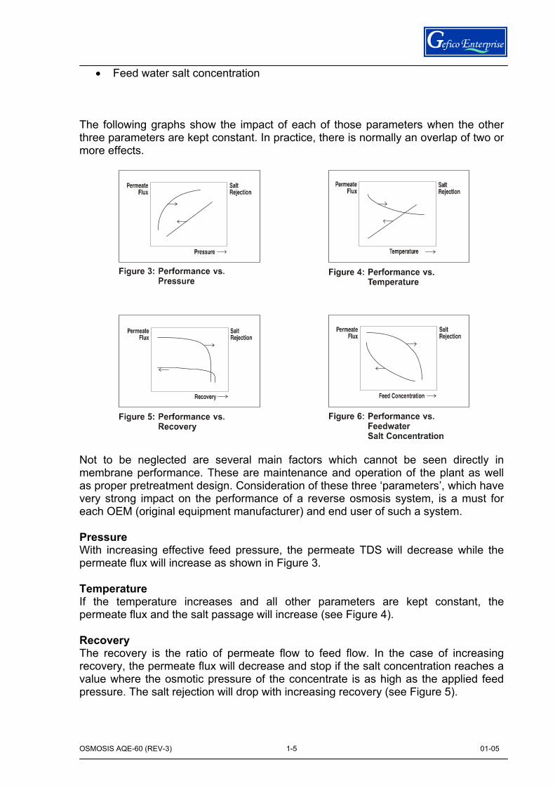
• Feed water salt concentration The following graphs show the impact of each of those parameters when the other three parameters are kept constant. In practice, there is normally an overlap of two or more effects. Not to be neglected are several main factors which cannot be seen directly in membrane performance. These are maintenance and operation of the plant as well as proper pretreatment design. Consideration of these three ‘parameters’, which have very strong impact on the performance of a reverse osmosis system, is a must for each OEM (original equipment manufacturer) and end user of such a system. Pressure With increasing effective feed pressure, the permeate TDS will decrease while the permeate flux will increase as shown in Figure 3. Temperature If the temperature increases and all other parameters are kept constant, the permeate flux and the salt passage will increase (see Figure 4). Recovery The recovery is the ratio of permeate flow to feed flow. In the case of increasing recovery, the permeate flux will decrease and stop if the salt concentration reaches a value where the osmotic pressure of the concentrate is as high as the applied feed pressure. The salt rejection will drop with increasing recovery (see Figure 5).
OSMOSIS AQE-60 (REV-3) 01-05
6
1-6
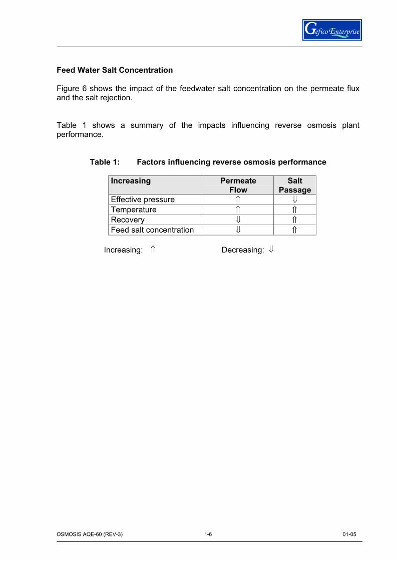
Feed Water Salt Concentration Figure 6 shows the impact of the feedwater salt concentration on the permeate flux and the salt rejection. Table 1 shows a summary of the impacts influencing reverse osmosis plant performance.
Table 1: Factors influencing reverse osmosis performance
Increasing Permeate Flow
Salt Passage
Effective pressure ⇑ ⇓ Temperature ⇑ ⇑ Recovery ⇓ ⇑ Feed salt concentration ⇓ ⇑
Increasing: ⇑ Decreasing: ⇓
OSMOSIS AQE-60 (REV-3) 01-05
7
1-7
1.2 GENERAL DESCRIPTION The GEFICO AQUAMAR ELECTRIC Reverse Osmosis (RO) plant is a self-contained unit requiring only connection to the various services, refer to the installation section of this manual. A general arrangement drawing for the plant is provided in Chapter 7 -Drawings. The plant comprises a skid on which are mounted a cartridge filtering system, one RO plant, model AQE-60, electric control panel and instrumentation. Booster seawater pump, sand filter, carbon filter (if required), seawater heating system for feed water temperature with automatic control (if required), dosing system (if required) and chemical cleaning system are supplied independently. In the RO plant, the raw water passes through a series of filters to extract any particles which might tend to clog the system. The filtered raw water is then piped to a high pressure pump, prior to entering the reverse osmosis membranes. The high pressure pump is protected by a low pressure switch at its inlet to ensure that there is always a flow while the pump is running. Raw water pressure within the reverse osmosis membranes is maintained by a pressure regulating valve at the outlet. The concentrated water (brine) which is discharged from the reverse osmosis membrane is then piped to overboard. Desalinated water which has passed through the reverse osmosis membranes is described as permeate or product water. The product water produced must be of an acceptable quality before it is directed into the water storage system. Product water quality is measured by conductivity. The lower the conductivity, the better the water quality. The quality is monitored by an electronic salinity monitoring instrument placed inside the electrical panel. This instrument controls a pair of valves to either accept or reject the product water. Product water that is rejected is discharged to overboard using the same line than the brine. The plant may be used to produce potable water or as a suitable feed for industrial cooling water system.
OSMOSIS AQE-60 (REV-3) 01-05
8
1-8
1.3 PROCESS DESCRIPTION Reference should be made to the Piping and Instrumentation drawing included in Section 7 of this Manual. 1.3.1 Production of potable water The following describes the process for a single Reverse Osmosis (RO) Plant, as shown on the P&ID. Start up First at all always check that all valves are in their correct position. Electrical control panel include pump starters. High pressure control valve must be always full open during start-up and must be slowly closed (1 bar per second) until to reach the requires capacity increasing the pressure on the membranes. Pre treatments As the seawater enters the skid the temperature of the incoming water is monitored by a temperature gauge (T). If seawater temperature is below 25ºC, the capacity is reduced a 3% for each degree. For operation in low seawater temperatures a heater with automatic control temperature must be placed In seawater treatment the limiting factor is of a physical nature, i.e. the osmotic pressure caused by high TDS. So, only in very special cases, a dose of a chemical scale inhibitor may be injected into the feed line to reduce the formation of scale. A level sensor must be incorporated into the dosing tank to protect the dosing pump from running dry. Should the level sensor detect a low level in the tank, the dosing pump will stop, and an alarm signal will be sent to both the local control panel Media Filtration The removal of suspended and colloidal particles by media filtration is based on their deposition on the surface of filter grains, while the water flows through a bed of these grains (filter media). The quality of the filtrate depends on the size, surface charge and geometry of both suspended solids and filter media, as well as on the water analysis and operational parameters. With a well designed and operated filter, a SDI<5 can usually be achieved.
OSMOSIS AQE-60 (REV-3) 01-05
9
1-9
The most common filter media in water treatment are sand and anthracite. The effective grain size for fine sand filter is in the range of 0.35 to 0.5 mm, and 0.7 to 0.8 mm for anthracite filter. In comparison to single sand filter media, dual filter media with anthracite over sand permit more penetration of the suspended matter into the filter bed, thus resulting in more efficient filtration and longer runs between cleaning. The design depth of the filter media is normally about 0.8 m (31 inches) minimum. In the dual filter media, the filters are usually filled with 0.5 m (20 inches) of sand covered with 0.3 m (12 inches) of anthracite. There are two types of filters employed, gravity and pressure filters. As the filter vessel for pressure filtration is designed for pressurization, a higher pressure drop can be applied for higher filter beds and/or smaller filter grains and/or higher filtration velocities. The design filtration flow rates are usually 10-20 m/h, and the backwash rates are in the range of 40-50 m/h. For feed waters with a high fouling potential, flow rates of less than 10m/h and/or second pass media filtration is preferred. The available pressure is usually about 5 m of head for gravity filters, and 2 bar (30 PSI) to more than 4 bar (60 PSI) for pressure filters. During operation, influent water to be filtered enters at the top of the filter, percolates through the filter bed, and is drawn off through the collector system at the bottom. Periodically, when the differential pressure increase between the inlet and outlet of the filter is 0.3 to 0.6 bar (4 to 9 PSI) for the pressure filter, and about 1.4 m for the gravity filter, the filter is backwashed and rinsed to carry away the deposited matter. Backwash time is normally about 10 min. Frequent shut-downs and start-ups should be avoided, because each filter velocity increase will release previously deposited particulate matter. Carbon Filtration (option) When any free chlorine is present in the feed water an activated carbon filter should be included (as option). This dechlorinates the feed water, by allowing it to flow through a bed of activated carbon. The carbon "scrubs" the feed water and removes the chlorine. The maximum continuous quantity of free chlorine is limited to < 0,1 ppm. When FILMTEC FT30 membranes used in the reverse osmosis process, the RO feed must be dechlorinated to prevent oxidation of the membrane. FT30 membrane has some chlorine tolerance before noticeable loss of salt rejection is observed. Eventual degradation may occur after approximately 200 - 1,000 hours of exposure to one mg/l of free chlorine (200-1,000 ppm-h tolerance).
OSMOSIS AQE-60 (REV-3) 01-05
10
1-10
The rate of chlorine attack depends on various feedwater characteristics. Under alkaline pH conditions, chlorine attack is faster than at neutral or acidic pH. An acidic pH is anyhow preferred for a better biocidal effect during chlorination. Chlorine attack is also faster at higher concentrations of heavy metals (e.g. iron), which catalyze membrane degradation, and at higher temperatures. By comparison, some other polyamide RO membranes have essentially zero chlorine tolerance. The superior chlorine tolerance of the FT30 membrane can be attributed to the thicker barrier layer (about 2,000 Angstrom) and the fact that the polyamide is crosslinked. If dechlorination upsets occur in a FT30 RO system, and if corrected in a timely manner, membrane damage can be minimized. For chloramine the tolerance of the FT30 membrane is 300,000 ppm-h, which implies that dechlorination is not required. However, since chloramines are formed by adding ammonia to chlorine, it is possible that free chlorine will be present. Since this free chlorine can be damaging to the membrane, dechlorination should still be considered. Residual free chlorine can be reduced to harmless chlorides by activated carbon or chemical reducing agents. An activated carbon bed is very effective in dechlorination of RO feed water according to following reaction:
C + 2 CI2 + 2 H2O -------- 4 HCI + CO2 Grooved disc Filter To avoid clogging of the cartridge filters and the RO membranes by either organic or inorganic particles, the feed water is passed though a filtering system. The grooved disc filter (FL) acts as a second stage filter, removing suspended solids down to approximately 100 microns. Pressure gauges monitor the condition of the filter. Filter is fitted with diverting valves to allow backwashing (cleaning) whenever the pressure drop across the filter increases. Cartridge Microfiltration A cartridge filter with a pore size of less than 10 μm is the minimum pre-treatment required for every RO system. It is a safety device to protect the membranes and the high pressure pump from suspended particles. Usually it is the last step of a pre-treatment sequence. We use a pore size of 5 μm on second cartridge group. First cartridge group pore size is 60 μm. The better the prefiltration is, the less cleaning of the RO membranes is required.
OSMOSIS AQE-60 (REV-3) 01-05
11
1-11
When the silica concentration in the concentrate stream exceeds the theoretical solubility ,cartridge filtration with 1 μm pore size is recommended in order to minimise the interaction with iron and aluminium colloids. The filter should be replaced before the pressure drop has increased to the permitted limit, but latest after 3 months. Back flushable filters are not recommended because of their lower efficiency and higher bio-fouling risk. The cartridge filter should be made of a synthetic nondegradable material; e.g. nylon or polypropylene and equipped with a pressure gauge to indicate the differential pressure drop and thereby indicating the extent of its fouling. Regular inspections of used cartridges provide useful information regarding fouling risks and cleaning requirements. If the differential pressure across the filter increases rapidly, it is an indication of possible problems in the raw water supply or in the pretreatment process. The filter provides some degree of short-term protection for the membranes while corrective action is taking place. Replacing cartridge filters more often than every 1 to 3 months usually indicates a problem with the pre treatment. However, the cartridge filter is not meant to be a major component for the removal of high amounts of filterable solids. This would not only be an inefficient use of rather expensive filters, but would probably lead to premature failure of the membrane system due to the high probability that some of the unwanted material will break through. It may be considered however, to use upstream a second cartridge with larger pore size. The feed then passes through cartridge filters (FP1 and FP2). These units remove particles down 60 microns (first set) and down 5 microns (second set), which is an acceptable level for entry into the RO pressure vessels. These filters are also monitored by pressure gauges. When pressure drop is higher than 3 bar, the cartridge must be replaced. High Pressure Feed Pump (BA) Once the sea water has passed through the cartridge filters (FP1 and FP2), it enters the high pressure system. For Reverse Osmosis to work, the feed pressure needs to be boosted, to approximately 60 bar, this is achieved by using a High Pressure Positive Displacement Pump (BA) To avoid cavitations and eliminate vibration of the HP Pump, suction is fitted with plastic hose and discharge line is fitted with pulsation dampers. These hose and damper (AI) smooth out the pulses of high pressure feed produced by the pump, and ensure that an uniform high pressure feed reaches the membrane modules.
OSMOSIS AQE-60 (REV-3) 01-05
12
1-12
Pressure Gauges and Pressure Switches (P2, PB, PA,) are positioned to monitor any problems that could arise from over pressurisation or low pressure feed. Pressure switches and gauges monitor low pressure on the suction side to prevent the pump running dry, and to minimise the problems of cavitations, and high pressure on the discharge side to protect the high pressure system. In some cases (as option) a pressure relief valve (VSA) set to operate at a pre-defined limit is installed downstream of the discharge pulsation damper as an extra protection. Maximum suction pressure for High Pressure Pump is 10 bar (g). High Pressure RO Membrane Vessels The high pressure feed enters the membrane modules, and is pumped through the elements causing water to diffuse through the semi-permeable membranes, whilst rejecting most of salts, thus the permeate is separated from the rejected brine, which is rejected back to the sea. The resulting permeate is now in a suitable state to be used as domestic or potable water. Solenoid Activated Valves (V8 & V9) As a fail safe to monitor the quality of the permeate produced, the salinity of the permeate is measured down stream of the membrane module. A salinometer is used to monitor the conductivity of the permeate (SAL-1), this is connected to two solenoid actuated valves, (V-8 and V-9). The first is situated in the main permeate line, and the second in a dump line. The dump line is closed when the coil is energised, and the main line is open. However should any excessive salinity be detected (by an increase in conductivity), the solenoid valves reverse there-by closing the main line, and opening the dump line, and allowing the contaminated permeate to be separated from the uncontaminated permeate already produced, and thus protecting the potable water. High salinity permeate is dumped to the brine line If one of the solenoid valves malfunctioned, both valves would be shut at the same time, thus causing pressure to build up in the permeate line and damage the membrane elements; to prevent this situation occurring a pressure relief valve, as option (VSP) can be installed to prevent excessive back pressure building up. Permeate The good quality permeate (<500 ppm) will now flow to the skid edge for distribution by the client. A permeate production meter is installed on the panel to check the unit production.
OSMOSIS AQE-60 (REV-3) 01-05
13
1-13
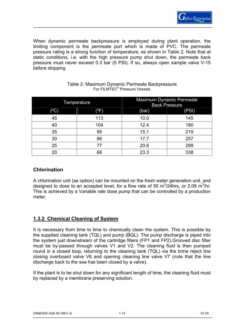
When dynamic permeate backpressure is employed during plant operation, the limiting component is the permeate port which is made of PVC. The permeate pressure rating is a strong function of temperature, as shown in Table 2. Note that at static conditions, i.e. with the high pressure pump shut down, the permeate back pressure must never exceed 0.3 bar (5 PSI). If so, always open sample valve V-15 before stopping
Table 2: Maximum Dynamic Permeate Backpressure For FILMTEC® Pressure Vessels
Temperature Maximum Dynamic Permeate Back Pressure
(ºC) (ºF) (bar) (PSI) 45 113 10.0 145 40 104 12.4 180 35 95 15.1 219 30 86 17.7 257 25 77 20.6 299 20 68 23.3 338
Chlorination A chlorination unit (as option) can be mounted on the fresh water generation unit, and designed to dose to an accepted level, for a flow rate of 50 m3/24hrs, or 2.08 m3/hr. This is achieved by a Variable rate dose pump that can be controlled by a production meter. 1.3.2 Chemical Cleaning of System It is necessary from time to time to chemically clean the system. This is possible by the supplied cleaning tank (TQL) and pump (BQL). The pump discharge is piped into the system just downstream of the cartridge filters (FP1 and FP2).Grooved disc filter must be by-passed through valves V1 and V2. The cleaning fluid is then pumped round in a closed loop, returning to the cleaning tank (TQL) via the brine reject line closing overboard valve V6 and opening cleaning line valve V7 (note that the line discharge back to the sea has been closed by a valve). If the plant is to be shut down for any significant length of time, the cleaning fluid must by replaced by a membrane preserving solution.

OSMOSIS AQE-60 (REV-3) 01-05
14
1-14
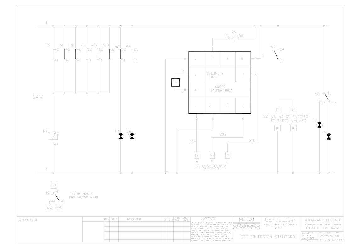
1.4. CONTROL AND PROTECTION The reverse osmosis plant is provided with a comprehensive control and instrumentation package for monitoring the system performance. All instrumentation is fitted on a control panel for easy unit operation and control showing pressures, temperatures and flows The local electrical control panel (placed on the module) contains electrical motors starters, operation hour counter meter, conductimetric unit (salinometer) used to monitor and control the plant. Remote free voltage alarm provision is made for remote indication. 1.4.1. Salinometer Specification Function: The SALINOMETER measure supervises the salinity (salt
content of permeated water produced by R.O.unit. Mains: Internal supply 24V-50/60Hz. Power: Max.160 W., dependent of the consumption of the
externally connected devices. Test: By means of the control knob the salinometer can be
checked. Internal Cable connections:
Terminals 2-10: Mains Terminals 3-4: Display Terminals 1-6: N.O solenoid valve. Terminals 6-11: N.C. Normally energised solenoid
valve. Terminals 5-8-9: Electrode unit. (cell)
High Salinity Alarm: Adjusting the Knob wheel trimming potentiometer
accessible by hand in the front of the salinometer box can change the alarm level. (See enclosed data sheet).
Range: The display reads the salinity in ppm´s of sea salt. If
salinity exceeds the alarm set point it is indicated by external red lamp and an internal two colours led changing from green to red.
Scale 0 to 1000 ppm of chlorides.
OSMOSIS AQE-60 (REV-3) 01-05
15
1-15
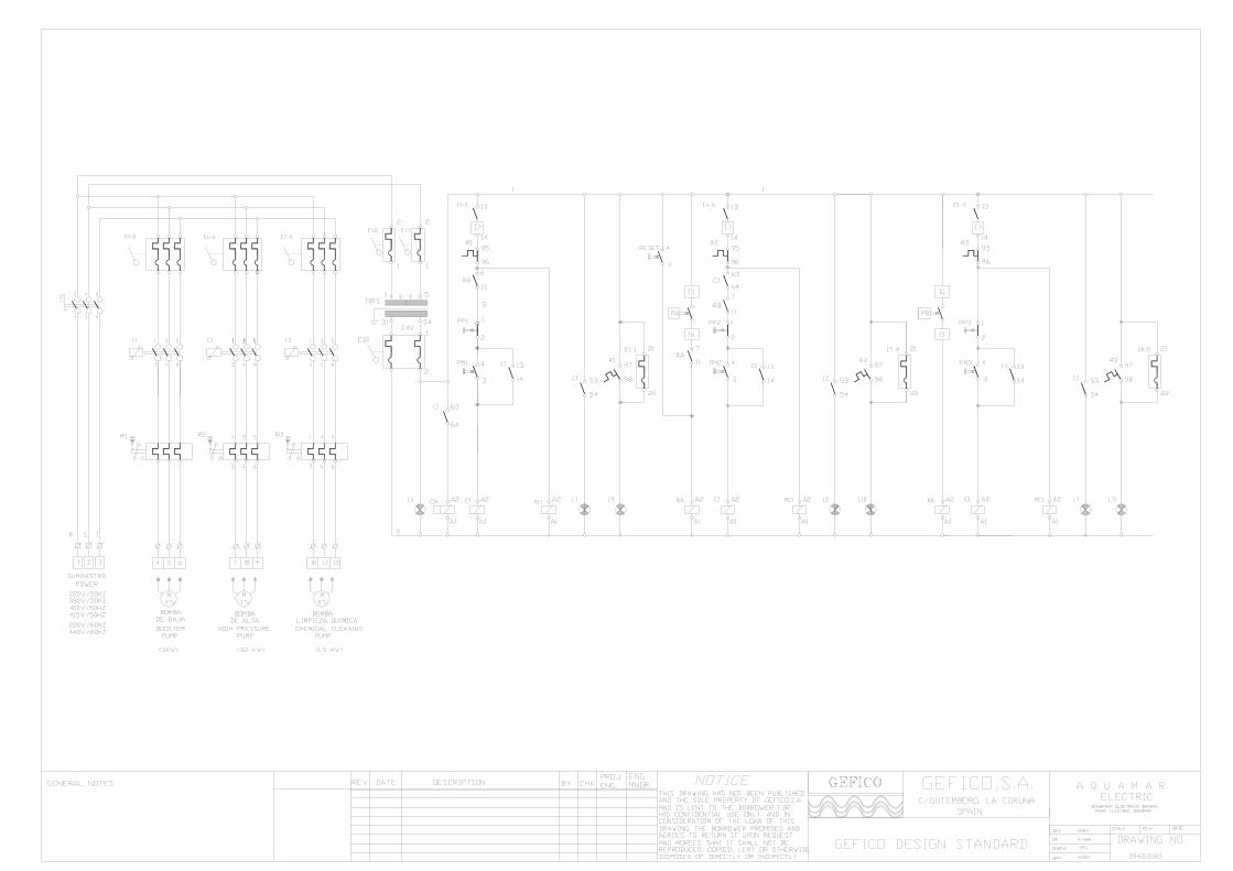
1.4.2.- Electric Design The mains transformer TRF1 supplies power to the salinometric unit. An internal transformer supplies power to electronic components. An auxiliary winding deliver the necessary signals to the electrode unit (terminals 8 and 9). The current is converted to voltage. The signal is then rectifier. A DC voltage equal to the peak value of the alternating input signal is derived and connected to signal input of an analogy amperemeter. A DC signal, the level of which is dependent on the setting of alarm/adjust, is connected to the non inverting input of the comparator. A current proportional to the conductance of the electrode unit at constant salinity (varying with varying temperature) enters at terminal 5. The current is again converted to voltage and rectifier. The rectifier signal is applied to reference input of the display. The ratio of the two signals applied to the display is the salinity, which is displayed on the amperemeter. Normally (I.E. at low salinity) the internal micro-relay is excited. When the DC voltage in the non-inverting input of the comparator exceeds the reference voltage (proportional to the temperature correction signal) the transistor is cut. Micro-relay changes state and the external alarm devices, connected to the relay contacts, can operate. On alarm red lamp is lighting and general alarm relay (RAL) is activated. The meter reading can be tested by a portable test resistor which is inserted between the electrodes of the salinity cell and is a dummy load of the specified salinity to make an overcheck of the system. This unit contents fixed resistors and potentiometer to adjust the test temperature and compensate the variation of conductivity. If all parts are functioning properly, a reading on the meter should be approximately 5 ppm. The reading should not be taken before the cell has reached room temperature in not less than 20 minutes after it has been removed from the pipes. 1.4.3.- Mechanical Design The salinometer is housed in a electrical panel. The PC board with all electronics circuits is mounted on a small close plastic box. By means of eleven-pin base the salinometer is connected to the terminal strip and all the other components. The electrode unit consists of a bronze piece with 1" thread. Two Monel electrodes and one temperature-compensating element are places within the distillate manifold block in such a way that they are easily removed for inspection.
OSMOSIS AQE-60 (REV-3) 01-05
16
1-16
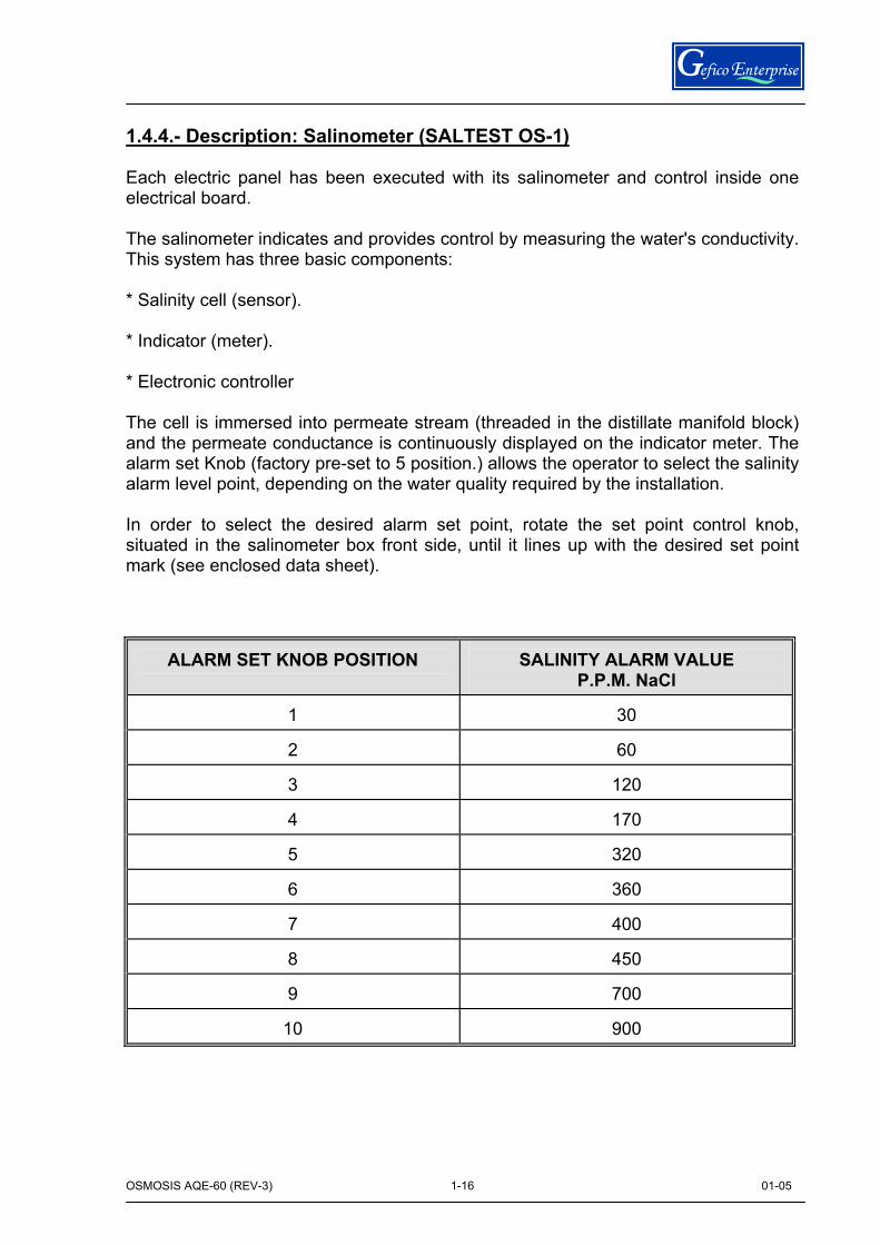
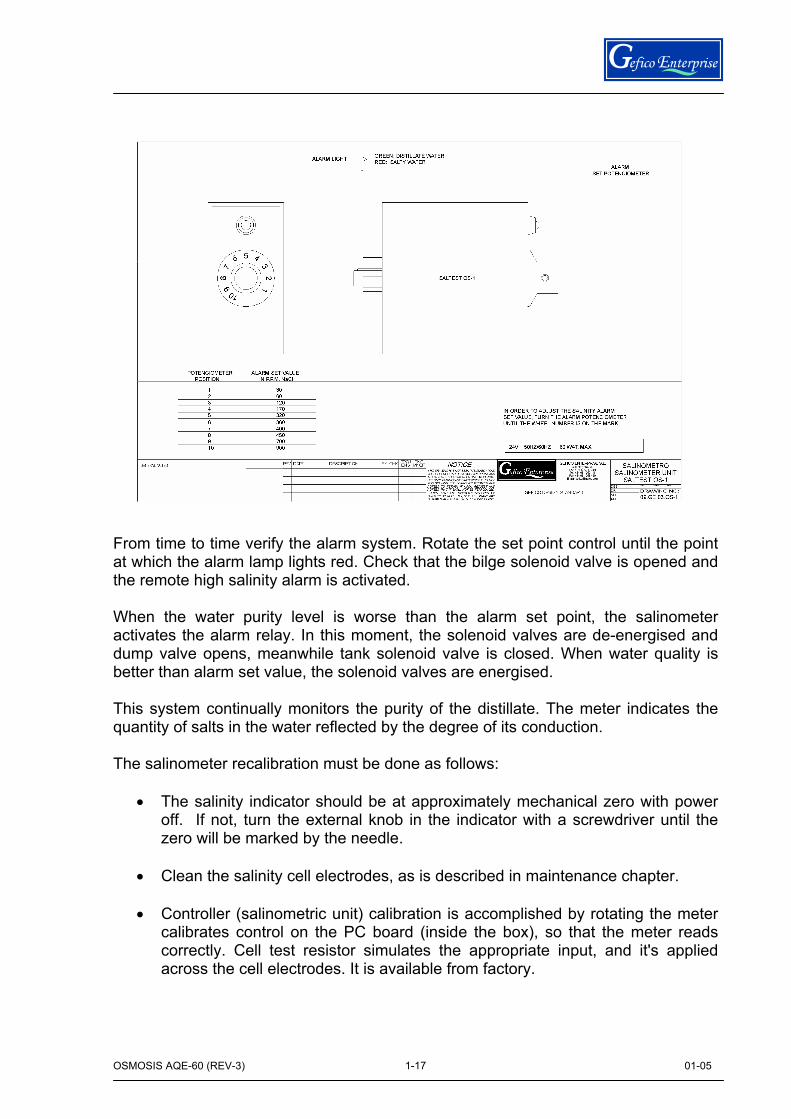
1.4.4.- Description: Salinometer (SALTEST OS-1) Each electric panel has been executed with its salinometer and control inside one electrical board. The salinometer indicates and provides control by measuring the water's conductivity. This system has three basic components: * Salinity cell (sensor). * Indicator (meter). * Electronic controller The cell is immersed into permeate stream (threaded in the distillate manifold block) and the permeate conductance is continuously displayed on the indicator meter. The alarm set Knob (factory pre-set to 5 position.) allows the operator to select the salinity alarm level point, depending on the water quality required by the installation. In order to select the desired alarm set point, rotate the set point control knob, situated in the salinometer box front side, until it lines up with the desired set point mark (see enclosed data sheet).
ALARM SET KNOB POSITION
SALINITY ALARM VALUE P.P.M. NaCl
1
30
2
60
3
120
4
170
5
320
6
360
7
400
8
450
9
700
10
900
OSMOSIS AQE-60 (REV-3) 01-05
17
1-17
From time to time verify the alarm system. Rotate the set point control until the point at which the alarm lamp lights red. Check that the bilge solenoid valve is opened and the remote high salinity alarm is activated. When the water purity level is worse than the alarm set point, the salinometer activates the alarm relay. In this moment, the solenoid valves are de-energised and dump valve opens, meanwhile tank solenoid valve is closed. When water quality is better than alarm set value, the solenoid valves are energised. This system continually monitors the purity of the distillate. The meter indicates the quantity of salts in the water reflected by the degree of its conduction. The salinometer recalibration must be done as follows:
• The salinity indicator should be at approximately mechanical zero with power off. If not, turn the external knob in the indicator with a screwdriver until the zero will be marked by the needle.
• Clean the salinity cell electrodes, as is described in maintenance chapter.
• Controller (salinometric unit) calibration is accomplished by rotating the meter
calibrates control on the PC board (inside the box), so that the meter reads correctly. Cell test resistor simulates the appropriate input, and it's applied across the cell electrodes. It is available from factory.
OSMOSIS AQE-60 (REV-3) 01-05
18
1-18
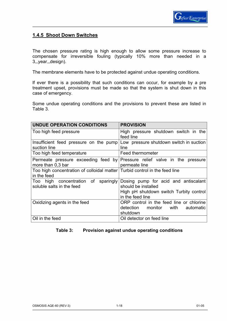
1.4.5 Shoot Down Switches The chosen pressure rating is high enough to allow some pressure increase to compensate for irreversible fouling (typically 10% more than needed in a 3 year design). The membrane elements have to be protected against undue operating conditions. lf ever there is a possibility that such conditions can occur, for example by a pre treatment upset, provisions must be made so that the system is shut down in this case of emergency. Some undue operating conditions and the provisions to prevent these are listed in Table 3. UNDUE OPERATION CONDITIONS PROVISION Too high feed pressure High pressure shutdown switch in the
feed line Insufficient feed pressure on the pump suction line
Low pressure shutdown switch in suction line
Too high feed temperature Feed thermometer Permeate pressure exceeding feed by more than 0,3 bar
Pressure relief valve in the pressure permeate line
Too high concentration of colloidal matter in the feed
Turbid control in the feed line
Too high concentration of sparingly soluble salts in the feed
Dosing pump for acid and antiscalant should be installed High pH shutdown switch Turbity control in the feed line
Oxidizing agents in the feed ORP control in the feed line or chlorine detection monitor with automatic shutdown
Oil in the feed Oil detector on feed line
Table 3: Provision against undue operating conditions

OSMOSIS AQE-60 (REV-3) 01-05
19
1-19
1.4.6. Relief Valves There are placed 3 relief valves: High pressure circuit At H. P. Pump discharge manifold (plug) safety valve is
placed. This valve is adjusted at 75 bar (g) to prevent damages on the circuit and do an additional protection of accessories.
Brine discharge circuit A safety valve can be installed on this line to avoid
problems of obstruction of the circuit and damage on this line. This valve is settled at 5 bar(g).
Permeate circuit A safety valve can be installed on this live to avoid
problems of obstruction of the circuit and damage. This valve is settled at 4 bar(g).
OSMOSIS AQE-60 (REV-3) 01-05
20
1-20
1.5 STANDARD VALVES Several valves are included in AQUAMAR RO units module for proper operation. There are other valves that must be placed on the installation by fitter, like: Inlet / Outlet valves to shut down the cleaning tank. Inlet / Outlet valves to shut down the activate carbon filter (dechlorinator). Inlet valve to shut down the seawater booster pump. Outlet check valve to shut down and control flow of the booster pump. Inlet / Outlet valves to shut down the chemical dosing tank. Overboard check valve. Check valve and atmospheric drain valve on permeate line to prevent the permeate pressure from exceeding the feed pressure. Valve in the permeate line to provide permeate drain during cleaning and start up. Safety valves on the circuits can be installed 1.6 CONTROL INSTRUMENTS To ensure proper operation of the RO AQUAMAR ELECTRIC Module a number of control instruments are placed. The accuracy of all instruments are guaranteed to obtain correct readings. Pressure gauges to measure the pressure drop across the cartridge filter, the pressure on the pump inlet line and discharge line, the feed pressure to the membrane elements and the pressure in the permeate line. Stainless steel pressure gauges with glycerine are installed on the module. Flow meters to measure concentrate and total permeate flow rate. Hour meter to log the total operating time is placed on electrical panel. When pH control is required, a pH meter in the feed line after acidification to control carbonate scaling potential can be install Conductivity meters in the permeate line to determine permeate quality .
OSMOSIS AQE-60 (REV-3) 01-05
21
1-21
1.7. TANKS Storing water in tanks should be generally kept at a minimum. When tanks are used, the inlet and outlet should be placed so that no stagnant zones are permitted. The tanks should be protected from dust and microbiological contamination. In critical applications tanks are closed and vented through a HEMA-filter. A feed tank is needed to provide the reaction time (20-30 min.) when chlorine is used. The free volume of media filters can be used for this purpose as well. Feed tanks are also frequently used as a buffer to allow continuous operation of the RO section (e.g. during backwash of filters). A permeate tank is typically employed, when the permeate is the product. Plant start-ups and shutdowns can be initiated by low level and high level from the permeate tank. The system capacity and the tank size should be designed so that the RO plant is allowed to run for some hours continuously. The less frequently the plant is shut down, the better is the system performance. A draw-back tank is a small tank in the permeate line that provides enough volume for natural osmosis backflow when the system shuts down. A missing draw back tank can cause air to be sucked into the FILMTEC elements. This may create the following problems:
Contamination of the permeate side of the membrane by airborne microbes and fungi.
Hydraulic shocks and slugs of air upsetting meters and set point controllers when the air is expelled from the system on the next start up.
Drying of the membrane (flux loss).
lf the feedwater is in a reduced status and contains H2S, Fe2+, Mn2+ , etc., the air intrusion may cause fouling of the membrane by oxidized and precipitated colloidal matter.
lf the product water from an RO system is chlorinated, care must be exercised to ensure that the chlorine does not migrate back to the membrane. Air breaks should be employed appropriately.
lf a draw-back tank is used, its water level should be higher than the highest pressure vessel, but not exceeding 3 m from the lowest vessel. To prevent contamination, the flow is in at the bottom and out the top, and the tank must be covered. Post-chlorination if performed must be done downstream of this tank.
OSMOSIS AQE-60 (REV-3) 01-05
22
1-22
The volume of the draw-back tank can be sized as follows:
VDBT = 25 NE -VPP
VDBT: Volume of draw-back tank (in litre)
NE: Number of installed element
VPP: Volume of permeate piping between pressure vessels and draw-back tank (in litre)
Dechlorination filter (carbon filter) can be placed between the hydrosphere fresh water tank and the inlet valve V3 to provide fresh water free of chlorine for osmosis backflow when the system shuts down or for chemical dosing tanks refillings. So, the draw back tank is not needed. Dosing tanks are required when chemicals are added to the feed water. They should be sized typically for a daily refill (if possible). Cleaning tank is required for cleaning procedure.
The pH of cleaning solutions used with FILMTEC elements can be in the range of 2 to 12, and therefore non-corrosive materials should be used in the cleaning system.
The mixing tank should be constructed of polypropylene or fibreglass reinforced plastic (FRP). The tank should be provided with a removable cover and a temperature gauge.
The cleaning procedure is more effective when performed at an elevated temperature. It is not recommended to use a cleaning temperature below 15ºC (59ºF) because of the very slow cleaning rate at low temperatures. In addition, some chemicals, such as sodium lauryl sulphate might precipitate at low temperatures. Cooling may also be required to avoid overheating, so heating / cooling requirements must be considered.
A rough rule of thumb in sizing a cleaning tank is to use approximately the empty pressure vessel volume and then add the volume of the feed and return hoses or pipes.
For example, to clean three 8-inch diameter pressure vessels with one elements per vessel, the following calculations would apply.
OSMOSIS AQE-60 (REV-3) 01-05
23
1-23
NOTICEDATEREV BYDESCRIPTION ENGMNGRENG
PROJCHK
GEFICO DESIGN STANDARD
GEFICO ENTERPRISE S.L.
LA CORUÑA - SPAINTel. +34 981 250 111Fax +34 981 258 439
E-mail [email protected]
GUTEMBERG 32
DATE:
DRAWING NO:APP:APP:
DR:DES: SCALE JOB NO:
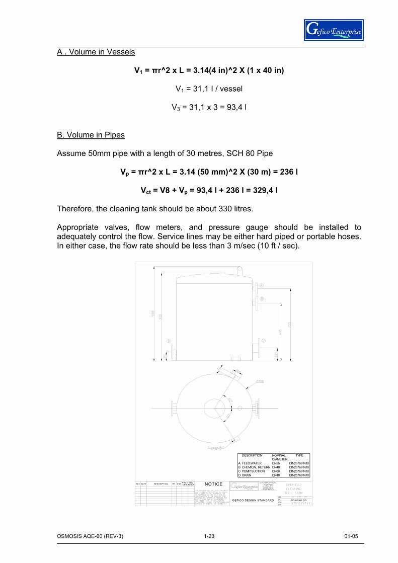
A . Volume in Vessels
V1 = πr^2 x L = 3.14(4 in)^2 X (1 x 40 in)
V1 = 31,1 I / vessel
V3 = 31,1 x 3 = 93,4 l B. Volume in Pipes Assume 50mm pipe with a length of 30 metres, SCH 80 Pipe
Vp = πr^2 x L = 3.14 (50 mm)^2 X (30 m) = 236 l
Vct = V8 + Vp = 93,4 l + 236 l = 329,4 l Therefore, the cleaning tank should be about 330 litres. Appropriate valves, flow meters, and pressure gauge should be installed to adequately control the flow. Service lines may be either hard piped or portable hoses. In either case, the flow rate should be less than 3 m/sec (10 ft / sec).
DESCRIPTION NOMINAL TYPEDIAMETER
A FEED WATER DN25 DIN2576,PN10B CHEMICAL RETURN DN40 DIN2576,PN10C PUMP SUCTION DN80 DIN2576,PN10D DRAIN DN40 DIN2576,PN10
OSMOSIS AQE-60 (REV-3) 01-05
24
1-24
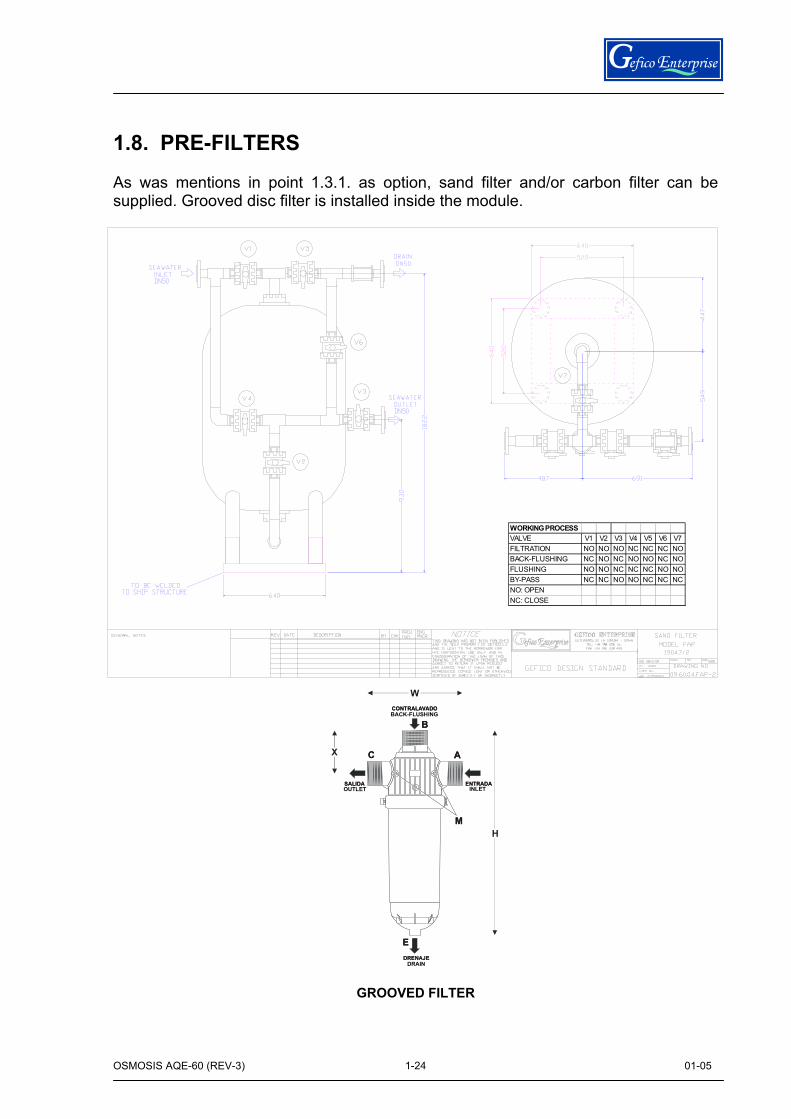
1.8. PRE-FILTERS As was mentions in point 1.3.1. as option, sand filter and/or carbon filter can be supplied. Grooved disc filter is installed inside the module.
ENTRADASALIDA
A
B
C
E
M
DRENAJE
CONTRALAVADO
W
H
X
ENTRADASALIDA
A
B
C
E
M
CONTRALAVADO
W
H
X
DRAIN
INLETOUTLET
BACK-FLUSHING
GROOVED FILTER
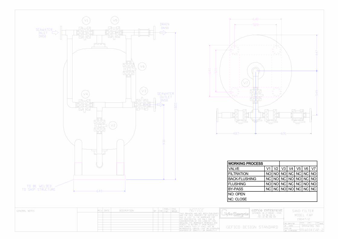
WORKING PROCESSVALVE V1 V2 V3 V4 V5 V6 V7FILTRATION NO NO NO NC NC NC NOBACK-FLUSHING NC NO NC NO NO NC NOFLUSHING NO NO NC NC NC NO NOBY-PASS NC NC NO NO NC NC NCNO: OPENNC: CLOSE
OSMOSIS AQE-60 (REV-3) 01-05
1
2-1
SECTION 2
TECHNICAL DETAILS
2.1 TECHNICAL DATA Client Usage Seawater treatment GEFICO serial number Plant type AQE-60 Product water output 50 m3/24 hrs (for potable water production) Product water salinity < 500 ppm (1000 micro-Siemen/cm) Product water discharge pressure 2,5 bar(g) Recovery ratio 25% Feed water flow rate 8,32 m3/hr Feed water pressure required 2 -5 bar(g) Feed water total dissolved solids 38000 mg/l (maximum) Feed water temperature 25°C (for rated product output) 29°C (maximum) 1°C (minimum) Power supplies 400V/3ph/50Hz
440V/3ph/60Hz 25 kW (Installed)
21 kW (Absorbed) 24VAC (control signals)
OSMOSIS AQE-60 (REV-3) 01-05
2
2-2
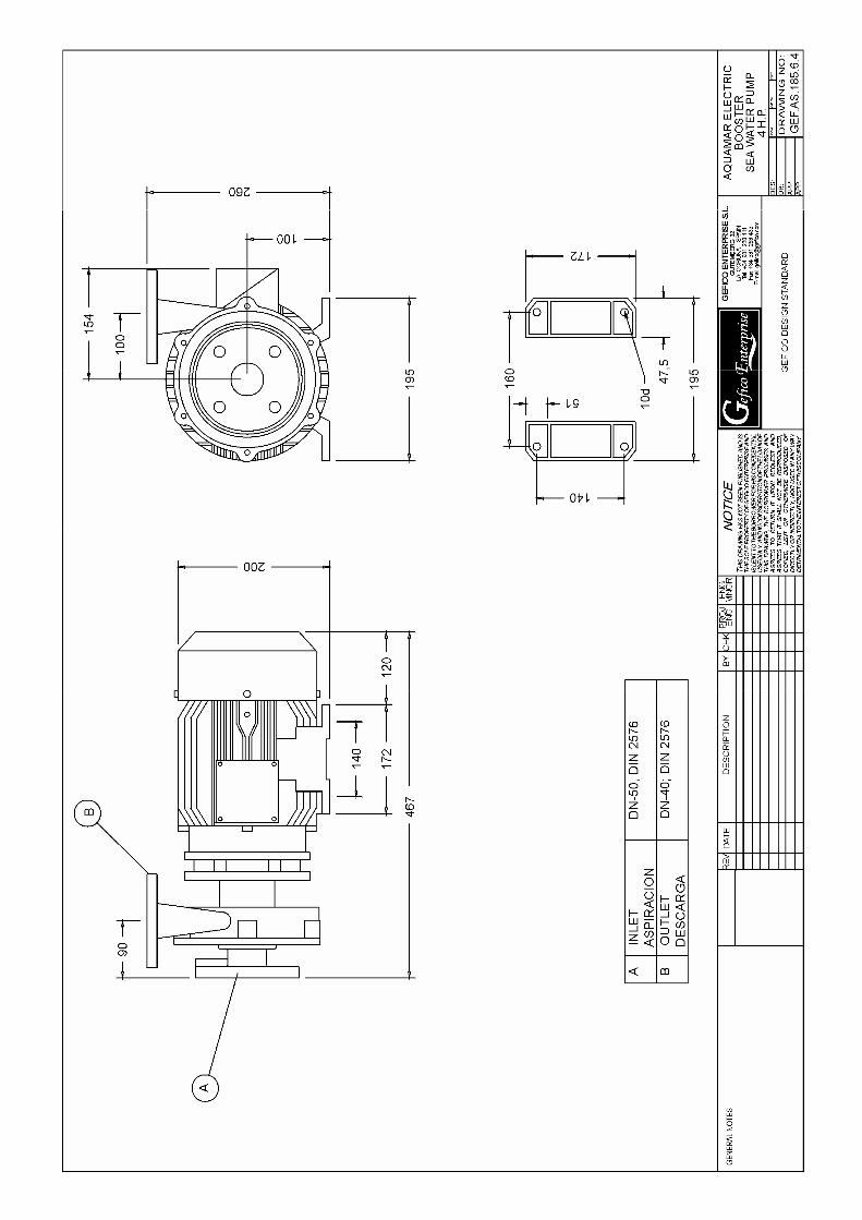
2.2 EQUIPMENT SPECIFICATION CAUTION The information included here is for reference purpose only. Spare or replacement parts should be ordered from GEFICO ENTERPRISE quoting the information provided here and in Section Spare-Parts List, in order to ensure compatibility with the original equipment supplied. Booster Feed Seawater Pump Model GEF-AS-185-6-4 Materials Bronze casting Type Horizontal centrifugal monoblock Flow capacity 25 m3 /hr NPSH 3 m.w.c. Discharge pressure 4,5 bar(g) (maximum) Speed 2860/3480 rpm Motor type AEG, AM 100 LS2 Motor power 3 kW / 3,4 kW (installed)
2,5 kW (absorbed) Motor speed 2860rpm/3480 rpm Motor protection IP55 Sand Filter Model FAP19047/2 Total capacity 570 litres. Bottle diameter 896mm Filtration surface 0,63 m2. Bottle empty weight 115 kg. Gross grain sand weight 100 kg Fine grain sand weight 400 kg Anthracite weight 90 kg Max. Flow rate 12,6 m3/hr Backwash flow rate 20 m3/hr Cleaning pressure drop 1 bar(g) Operating pressure Between 2 and 6 bar(g) Drw. Nº 09.60.04.FAP-2
OSMOSIS AQE-60 (REV-3) 01-05
3
2-3
Grooved Disc Filter System Helix Model 2NR Max. Flow rate 30 m3/hr Backwash flow rate 10 m3/hr Initial pressure loss 0.1 bar Max. Operating pressure 10 kg/cm2(g) Max. Operating temperature 60ºC Lower pH value 4 (not use acid below pH=4) First Wound Filter Cartridge in Polypropylene Model Aqua big Size 20" Quantity 3 Housing Polypropylene Flow rate per filter 2,78 m3/hr Initial pressure loss 0.1 bar(g) Max. operating pressure 8 bar(g) Max. Differential pressure 3,5 bar Micro rating Down to 60 microns Second Wound Filter Cartridge in Polypropylene Model Aqua big Size 20" Quantity 3 Housing Polypropylene Flow rate per filter 2,78 m3/hr Initial pressure loss 0.2 bar(g) Max. operating pressure 8 bar(g) Max. Differential pressure 3,5 bar Micro rating Down to 5 microns
OSMOSIS AQE-60 (REV-3) 01-05
4
2-4
High Pressure Plunged Feed Pump Supplier SPECK TRIPLEX Model P62/175-120S Type 3 stage positive displacement pump Flow capacity 8320 litres/hr Suction pressure -0.3 to 10 bar(g) Max. discharge pressure 70 bar(g) Speed 648 rpm Motor type M2AA 180 L4 Motor power 22 kW (installed)
18,5 kW (absorbed) Motor speed 1470rpm/1770 rpm Rope and Pulley Supplier TEXROPE Model XPB 1900 Quantity 3 Type Narrow section without coat HFX Temperature -30ºC to 80ºC Nominal section 16.3*13 Width 14 Tension strength 90 daN Norms ISO4184, DIN7753 Pump speed 648 rpm Motor speed 1470/1770 rpm Pulsation damper Supplier SPECK TRIPLEX Model LAV-INOX. series Type LAV-0,5 Maximum operating pressure: 150 bar Gas filling: Nitrogen exclusively, max. 90% of operating
pressure. Admissible max.pressure ratio: < 6/1
OSMOSIS AQE-60 (REV-3) 01-05
5
2-5
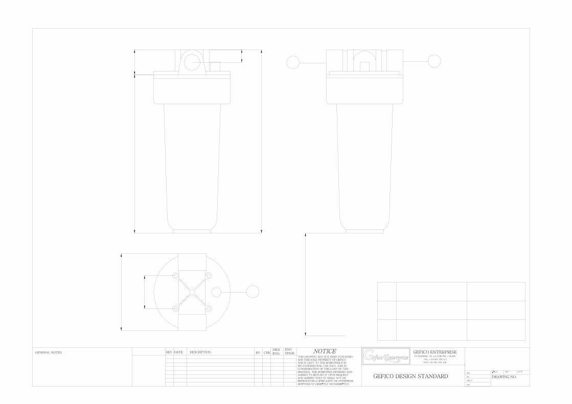
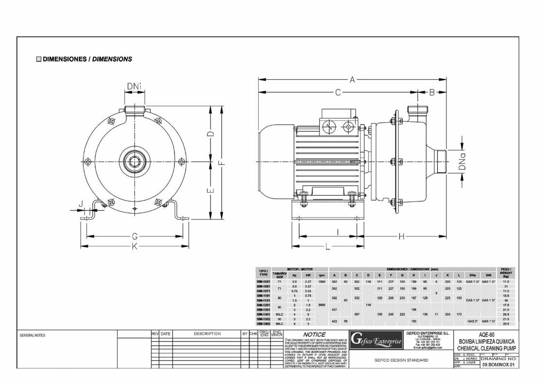
Max. dynamic pressure differential 125 bar Operating temperature range -15ºC to 80ºC Mounting at will Body AISI 316 Diaphragm NBR Gas Valve 5/8" UNF, version 1 Reverse Osmosis Array Membrane type SW30HR-380 Membrane number 3 Maximum operating pressure 70 bar Maximum operating temperature 40ºC Pressure vessels 8", OI80401A Vessel number 3 Maximum operating pressure 70 bar Maximum operating temperature 52ºC Chemical Cleaning Tank Material FRP Capacity 300 litres Model 01.OS60.01.001 Chemical Cleaning Pump (2,2 kw) Model SIM1302 Materials Stainless Steel Type Horizontal centrifugal monoblock Flow capacity 8 m3 /hr Discharge pressure 3 bar(g) (maximum) Speed 3000 rpm Motor power 2,2 kW (installed) Chemical pre-treatment Doser (Option) Material Plastic tank Capacity 130 I
OSMOSIS AQE-60 (REV-3) 01-05
6
2-6
Dosing rate 0,7 l/hr Recharge period 3 days Mixer CH-1 (Manual) Chemical pre-treatment Dosing pump (Option) Supplier Dosapro Milton Roy Type Mechanically actuated diaphragm
electromagnetic pump Model LMI- P133-391-SM Adjustable frequency: 1 to 60 or 100 str/min Adjustable stroke length: 0 to l00% Maximum output: 1,6 l/h Maximum pressure 7,6 bar Max. temp. of pumped chemical: 50 °C Self priming height: 1.5 m Accuracy: ± 2% of adjusted output Pump head and valves: PGC. Ceramic balls and Polyprel ® Composite pump diaphragms of the superior Fluorofilm ® assure reliable and leak free operation in a wide variety of chemicals. Uses LMI’s unique moulded long life Electromagnetic Power Unit (EPU) with electromagnetically balanced construction. Clog resistant injection check valves with flexible flapper nozzle are standard. LMI’s unique 4-Function Valve Fluorofilm ® is a copolymer of tetrafluoroethylene and perfluoroalkoxy. Polyprel ® is a copolymer of tetrafluoroethylene and propylene. Simple Rugged Construction ideal for indoor, outdoor and OEM "in machin" applications where simplicity means increased reliability. Thick wall fibber glass or carbon fibber reinforced thermoplastic construction plus integrated metal-plastic structural and magnetic components result in vibration and shock resistance not ordinarily found in competitive products. Strong automotive type wire and electrical connectors add to its construction strength. All pumps come complete with these accessories.
OSMOSIS AQE-60 (REV-3) 01-05
7
2-7
2.3 INSTRUMENTATION AND CONTROL CAUTION: The information included here is for reference purposes only.
Spare or replacement parts should be ordered from GEFICO ENTERPRISE quoting the information provided here and in Section 6 - Parts List, in order to ensure compatibility with the original equipment supplied.
NOTE For key to abbreviations and location of the instruments refer to P & I
diagram in Section 7 - Drawings of this manual. Three ways Ball Valve (V1, V2 and V6) Model Type 610 Size 50 Material PVC Nominal bore 1 1/2" (ND40) Nominal pressure NP16 Connections Union Ball Valve (V3 and V7) Model Type 50 Material PVC Nominal bore 1 1/2" (ND40) Connections Union By-pass Ball Valve (V5) Material Stainless Steel AISI-316 Nominal bore 1 " Connections Female thread
OSMOSIS AQE-60 (REV-3) 01-05
8
2-8
Non-Return Valve (V10) Model Fig 47 Material Stainless steel AISI 316 Connections 1" Brine Pressure Control Valve (V4) Material Stainless steel AISI 316 Type Adjustable needle pressure valve Ports 1" (F) Salinometer Supplier GEFICO ENTERPRISE Type SALTEST Model OS-1 Cell model 009-AQE-00 Range 0 – 1000 ppm Power supply 24Vac Low Pressure gauges Material Stainless steel Dial 64 mm Scale 0 to 6 bar Connection 1/4"(M), back High Pressure gauge Material Stainless steel Dial 64 mm Scale 0 to 100 bar Connection 1/4"(M), back
OSMOSIS AQE-60 (REV-3) 01-05
9
2-9
Digital feed sea water Thermometer (T) Model E5LC Scale 10-45ºC Feed Seawater Flowmeter (F1) Model R-009 Size 2" Scale 4 m3/h up to 14 m3/h Max.pressure 10 bar Material
Head PVC O´rings Viton Vessel Polysulfon Float Stainless steel 316
Permeate Flowmeter (F2) Model R-009 Size 2" Scale 400 l/h up to 4000 l/h Max. pressure 10 bar Material
Head PVC O´rings Viton Vessel Polysulfon Float Stainless steel 316
Low Pressure Switch (PB) Model PM Series Working pressure 0.15 to 10 bar Setting 0,5 bar(g) Contacts Open on falling pressure.
OSMOSIS AQE-60 (REV-3) 01-05
10
2-10
High Pressure Switch (PA) Model PMM80 CW Max. static pressure 150 bar Adjustment 50 bar to 80 bar Setting 70 bar(g) Contacts NC Max.operating voltage 48v Working temperature -5ºC to 60ºC Tightening torque max. 10 kgm Execution membrane NBR Material body AISI 316 Tank solenoid valve (V8) Model 262C-25V Max. Working pressure 10 bar Max. Temperature 60ºC Voltage 24V-50/60Hz. Tank solenoid valve (V9) Model 262A-25V Max. Working pressure 10 bar Max. Temperature 60ºC Voltage 24V-50/60Hz. H. P. Safety valve (VSA) Serie 963 Material Stainless steel AISI-316 Max. Working pressure 100 bar Max. Temperature 230ºC Connections 1/2"BSP * 3/4"BSP Set pressure 75 bar(g)
OSMOSIS AQE-60 (REV-3) 01-05
11
2-11
Permeate Safety Valve (VSP) Serie 396 Material Bronze casting RG-5 Max. Working pressure 16 bar Max. Temperature 230ºC Connections 1/2"BSP (M)* 3/4"BSP (H) Set pressure 4 bar(g) Brine Safety Valve (VSS) Serie 396 Material Bronze casting RG-5 Max. Working pressure 16 bar Max. Temperature 230ºC Connections 1/2"BSP (M)* 3/4"BSP (H) Set pressure 5 bar(g)
OSMOSIS AQE-60/35 03-03
32
4-32
SECTION 3
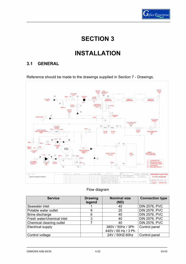
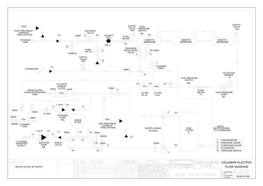
INSTALLATION 3.1 GENERAL Reference should be made to the drawings supplied in Section 7 - Drawings.
Flow diagram
Service Drawing
legend Nominal size
(ND) Connection type
Seawater inlet 1 40 DIN 2576, PVC Potable water outlet 8 25 DIN 2576, PVC Brine discharge 6 40 DIN 2576, PVC Fresh water/chemical inlet 3 40 DIN 2576, PVC Chemical cleaning outlet 7 40 DIN 2576, PVC Electrical supply 380V / 50Hz / 3Ph
440V / 60 Hz / 3 Ph Control panel
Control voltage 24V / 50HZ-60hz Control panel
FLOWMETER
F2SAL.1
MEDIAFILTER
V7
SAFETY
FILTERED
GEFICO SCOPE OF SUPPLY
SEAWATERSUPPLY
BB
BOOSTERPUMP
1 1/4"G 1"G
V4
DN50
CHECKVALVE
11
V1
CLEANINGTANK
DRAINDN25
DN40
CARBON
FILTER
DN65
DN20
TQL
FRESH WATERFROM HYDROPHORE
TANK
BQLPUMP
CLEANING
FILTER
1 1/4"G
DN20
FPC
1"G
DN20
OVERBOARD
ACTIVATE
13
SAMPLE
15
TANK BACKFLUSHING DISC
V3
DN50V2
DN50V6P
DRAIN 12
1
BY-PASS
DN40P1
FILTERFL
P1
PRE-TREATMENTCHEMICAL
DN40
TQL
3
VALVEVSS
DUMPVALVE
10
9
DN40
4
PRESSURE
VALVEREGULATING
FP2FP1
2
FILTER60 um
FILTER5 um
P1
6
P1 P1
CLEANINGDN40
BY-PASS
5
7
LOW PRESSURE
T
SWITCHPB
DN25
STORAGETANK
14
PRESSURESWITCH
SALINITYCELL
SOLENOIDVALVE
8 P1 FLOWMETER
VALVESAFETY
VSP
OSMOTICMEMBRANE
PAP2
HIGH
OSMOTICMEMBRANE
BACKFLUSHING
A.LINARESA.FERNANDEZ
A.FERNANDEZAFL
09.60.01.004
FLOW DIAGRAMAQUAMAR ELECTRIC
TO OVERBOARD
T THERMOMETERP PRESSURE GAUGEC COMPOUND GAUGEF FLOWMETERPI PRESSURE SWITCH
HIGH PRESSURE
DRAIN
F1BA
PUMP
PULSATIONDAMPER
AI
MEMBRANEOSMOTIC
VSA
SAFETYVALVE
OSMOSIS AQE-60/35 03-03
33
4-33
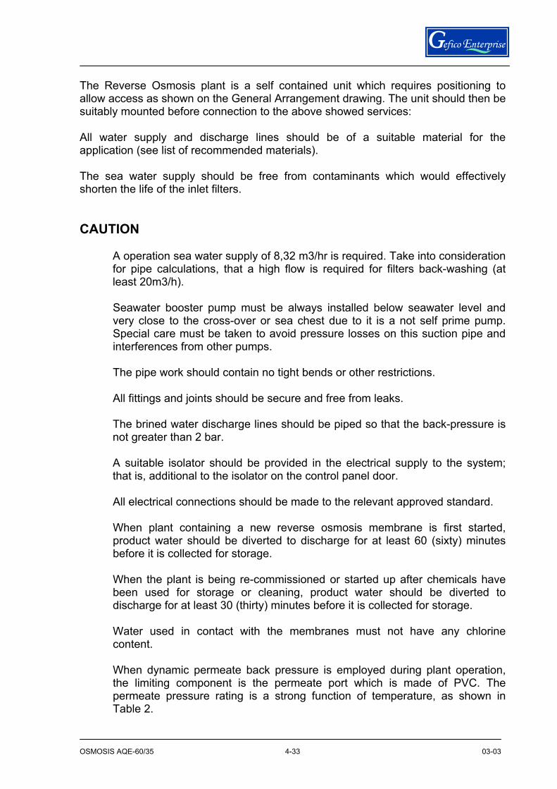
The Reverse Osmosis plant is a self contained unit which requires positioning to allow access as shown on the General Arrangement drawing. The unit should then be suitably mounted before connection to the above showed services: All water supply and discharge lines should be of a suitable material for the application (see list of recommended materials). The sea water supply should be free from contaminants which would effectively shorten the life of the inlet filters. CAUTION
A operation sea water supply of 8,32 m3/hr is required. Take into consideration for pipe calculations, that a high flow is required for filters back-washing (at least 20m3/h).
Seawater booster pump must be always installed below seawater level and very close to the cross-over or sea chest due to it is a not self prime pump. Special care must be taken to avoid pressure losses on this suction pipe and interferences from other pumps.
The pipe work should contain no tight bends or other restrictions. All fittings and joints should be secure and free from leaks.
The brined water discharge lines should be piped so that the back-pressure is not greater than 2 bar.
A suitable isolator should be provided in the electrical supply to the system; that is, additional to the isolator on the control panel door.
All electrical connections should be made to the relevant approved standard.
When plant containing a new reverse osmosis membrane is first started, product water should be diverted to discharge for at least 60 (sixty) minutes before it is collected for storage.
When the plant is being re-commissioned or started up after chemicals have been used for storage or cleaning, product water should be diverted to discharge for at least 30 (thirty) minutes before it is collected for storage.
Water used in contact with the membranes must not have any chlorine content.
When dynamic permeate back pressure is employed during plant operation, the limiting component is the permeate port which is made of PVC. The permeate pressure rating is a strong function of temperature, as shown in Table 2.
OSMOSIS AQE-60/35 03-03
34
4-34
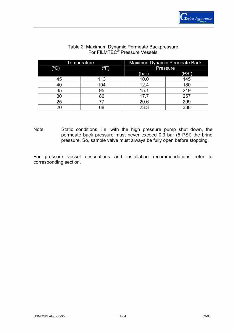
Table 2: Maximum Dynamic Permeate Backpressure For FILMTEC® Pressure Vessels
Note: Static conditions, i.e. with the high pressure pump shut down, the
permeate back pressure must never exceed 0.3 bar (5 PSI) the brine pressure. So, sample valve must always be fully open before stopping.
For pressure vessel descriptions and installation recommendations refer to corresponding section.
Temperature (ºC) (ºF)
Maximun Dynamic Permeate Back Pressure
(bar) (PSI) 45 113 10.0 145 40 104 12.4 180 35 95 15.1 219 30 86 17.7 257 25 77 20.6 299 20 68 23.3 338
OSMOSIS AQE-60/35 03-03
35
4-35
3.2.- MATERIALS OF CONSTRUCTION, CORROSION
CONTROL From a corrosion point of view a very harsh environment prevails in an RO water desalination plant. Hence the materials of construction must possess a certain degree of corrosion resistance. This counts for both the exterior parts exposed to spillage and a humid and saline atmosphere as well as for the interior of the system exposed to the wide variety of waters treated. Although not to be underestimated, the control of the exterior corrosion can usually be overcome by using a surface coating (painting, galvanizing, etc.) on materials supposed to corrode (mild steel, cast iron, etc.) and by establishing a maintenance program involving periodical flush down and cleaning, repair of leaks, etc. Selecting materials of construction for the interior wetted system is a far more complicated task. Apart from being compatible with the pressures, vibrations, temperatures, etc. existing in an RO system, the materials are also able to withstand the potential corrosion attacks caused by the high chloride content of the feed water, seawater attack, the concentrate stream, the aggressive product water and the chemicals used for applications such as membrane cleaning. Application of non-metallic materials such as plastics, fiber glass, etc. are used for preventing corrosion and chemical attacks as well in the low-pressure parts( < 16 bar) of the RO system as in the RO elements and pressure vessels. However, it is necessary to use metals for the high-pressure (16 - 70 bar) parts such as pumps, piping and valves. Carbon and low alloy steels do not have sufficient corrosion resistance, and their corrosion products can foul the membranes. Al-bronze can be an alternative for pumps, etc. The most relevant material to be used for the high-pressure parts is stainless steel. Stainless steel has as basic advantages that they are very resistant to general corrosion and erosion corrosion. Stainless steel is rarely attacked by galvanic corrosion, but it will influence the attack on the other metal in a two-metal couple (e.g. copper, brass, steel, etc.). Stress corrosion cracking of stainless steels in media containing chloride rarely occurs below 70°C (158°F) so it does not need to be considered in RO desalination plant. Unfortunately, some stainless steels are prone to pitting and crevice corrosion in the waters occurring in an RO plant.

OSMOSIS AQE-60/35 03-03
36
4-36
Pitting means localized attacks that result in holes in the metal. Pitting occurs where the passive film formed by chromium oxides breaks and chlorides can attack the bare metal. Crevice corrosion is pitting associated with small volumes of stagnant water caused by holes, gasket surfaces, deposits and crevices under bolts, etc. In order to avoid pitting and crevice corrosion in the RO water desalination plant the following recommendations must be followed: RO Plants with concentrate stream higher than 7,000 ppm: Stainless steel type 904 L is recommended for pipes and bends for welding and for similar parts without crevices. Where crevices occur, such as at flange connections, in valves, in pumps, etc. stainless steel type 254 SMO or alike with > 6% Mo is recommended. Sensor element of instruments may be coated or lined. The composition of the named stainless steels is given in Table 1.
Table 1:Composition of Stainless Steels:
Usual Designation UNS No. C% Cr% Ni% Mo% Cu% N%
AISI 316 S 31600 <0.08 16.0-18.0 10-14 2.0-3.0 - - AISI 316L S 31603 <0.03 16.0-18.0 10-14 2.0-3.0 - -
904 L N 08904 <0.02 19.0-23.0 23.0-28.0 4.0-5.0 1.0-2.0 - 254 SMO S 31254 <0.02 19.5-20.5 17.5-18.5 6.0-6.5 0.5-1.0 0.18-0.22
Besides the above recommendations general precautions must be taken during design, construction and installation, such as: Minimum of crevices and dead ends.
Design the piping so that the flow velocity is above 1.5 m/s (5 ft/s). It promotes the forming and maintenance of the passive film.
Use backing gas when welding in order to avoid the weld oxide film forming base for crevice corrosion.
Pickle and passivate the pipe system as this gives the optimum safety against chloride attack.
Flush the plant with low TDS water before a shut-down period.
OSMOSIS AQE-60/35 03-03
37
4-37
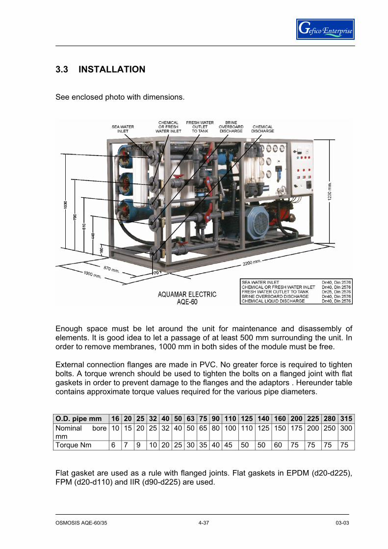
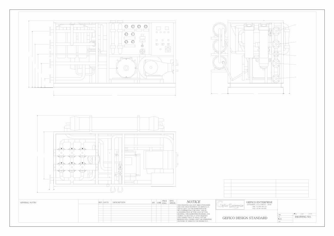
3.3 INSTALLATION See enclosed photo with dimensions.
Enough space must be let around the unit for maintenance and disassembly of elements. It is good idea to let a passage of at least 500 mm surrounding the unit. In order to remove membranes, 1000 mm in both sides of the module must be free. External connection flanges are made in PVC. No greater force is required to tighten bolts. A torque wrench should be used to tighten the bolts on a flanged joint with flat gaskets in order to prevent damage to the flanges and the adaptors . Hereunder table contains approximate torque values required for the various pipe diameters. O.D. pipe mm 16 20 25 32 40 50 63 75 90 110 125 140 160 200 225 280 315Nominal bore mm
10 15 20 25 32 40 50 65 80 100 110 125 150 175 200 250 300
Torque Nm 6 7 9 10 20 25 30 35 40 45 50 50 60 75 75 75 75 Flat gasket are used as a rule with flanged joints. Flat gaskets in EPDM (d20-d225), FPM (d20-d110) and IIR (d90-d225) are used.

OSMOSIS AQE-60/35 03-03
38
4-38
Sand filter must be installed in a place were they are accessible for minerals refilling and back-flushing procedure can be easily done. Before the filling with minerals, the filters must be filled with water until the middle of the vessel to avoid damage on filter elements and reduce the formation of dust. Filling must be done only 2/3 total height, 1/3 must be left as free space. Enough space must be let around the filters for maintenance and operation. The filling is done unthread the top register and the draining is done unthread the bottom register. So, enough height must be left on top and bottom.
OSMOSIS AQE-60 (REV-1) 03-03 4-39
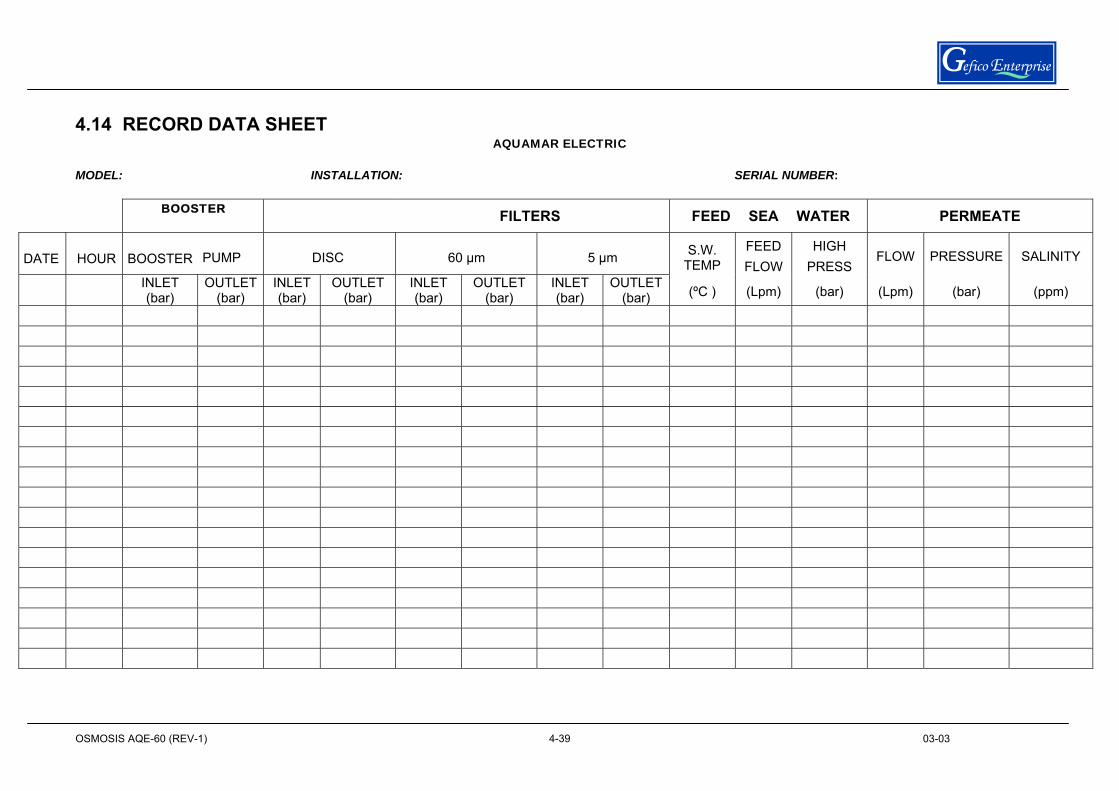
4.14 RECORD DATA SHEET AQUAMAR ELECTRIC
MODEL: INSTALLATION: SERIAL NUMBER:
BOOSTER FILTERS FEED SEA WATER PERMEATE
DATE HOUR BOOSTER PUMP DISC 60 µm 5 µm S.W. TEMP
FEED FLOW
HIGH PRESS
FLOW PRESSURE SALINITY
INLET (bar)
OUTLET (bar)
INLET (bar)
OUTLET (bar)
INLET (bar)
OUTLET (bar)
INLET (bar)
OUTLET(bar) (ºC ) (Lpm) (bar) (Lpm) (bar) (ppm)

OSMOSIS AQE-60 (DRW) 03-03 7-1
SECTION 7
DRAWINGS

OSMOSIS AQE-60 (DRW) 03-03 7-2
OSMOSIS AQE-60 (DRW) 03-03 7-3
METERFLOW
VALVESAFETY
V7
FILTERMEDIA
SUPPLYSEAWATER
GEFICO SCOPE OF SUPPLY
FILTEREDPUMP
BOOSTER
V4
DN50
VALVECHECK
V1
TANKCLEANINGDRAIN
DN25
DN40
CARBONDN20
DN20
DN65
FILTER
TANKFROM HYDROPHORE
FRESH WATER
CLEANINGPUMP
1"G1 1/4"G
FILTER DN20
OVERBOARD
ACTIVATE
SAMPLE
DISCBACKFLUSHING
V3
V6
DN50V2
P
DRAIN
1
DN40
BY-PASS FILTER
DN403
VALVEDUMP 9
DN40
REGULATING
4VALVE
PRESSURE
2
FILTER60 um
FILTER5 um
6
P1
DN40CLEANING
BY-PASS
5
7
LOW PRESSURE
T
SWITCHPB
TANKSTORAGE
DN25
SWITCHPRESSURE
HIGH
CELLSALINITY
SOLENOIDVALVE
8 P1METERFLOW
MEMBRANE
PA
OSMOTIC
P2
MEMBRANEOSMOTIC
BACKFLUSHING
PI PRESSURE SWITCHF FLOWMETERC COMPOUND GAUGEP PRESSURE GAUGET THERMOMETER
TO OVERBOARD
AQUAMAR ELECTRICFLOW DIAGRAM
HIGH PRESSURE
DRAIN
PUMP
DAMPERPULSATION
MEMBRANEOSMOTIC
VALVESAFETY
09.60.01.005
15
10
13
SAL.1 F2
AI
BAF1
P1P1FP1 FP2
FL
14
P1
P1
11
BB
TQL BQL TDQ
CHEMICALPRE-TREATMENT
TANK (OPTION)
12
A.FERNANDEZAFL
A.FERNANDEZA.LINARES
FPC
VSAVSP
SAFETYVALVE
VSS
1 1/4"G 1"G
DN50V5
TDQ2
CHEMICALPOST-TREATMENT
TANK (OPTION)
OSMOSIS AQE-60 (DRW) 03-03 7-4
WORKING PROCESSVALVE V1 V2 V3 V4 V5 V6 V7FILTRATION NO NO NO NC NC NC NOBACK-FLUSHING NC NO NC NO NO NC NOFLUSHING NO NO NC NC NC NO NOBY-PASS NC NC NO NO NC NC NCNO: OPENNC: CLOSE
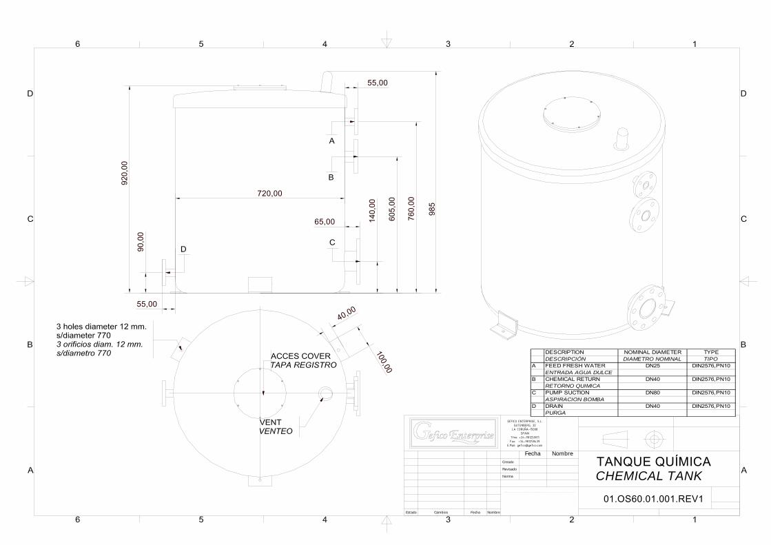
140,
00
605,
00
90,0
0
720,00
920,
00
985
100,00
40,0055,00
65,00
55,00
760,
00
TANQUE QUÍMICACHEMICAL TANK
01.OS60.01.001.REV1Estado Cambios Fecha Nombre
Creado
Revisado
Norma
Fecha Nombre
NOTICE.
TH IS DRAWING HAS NOT BEEN PUBLISHED AND IS THE SOLE PROPERTY OF GEFICO ENTERPR ISE A ND IS LENT TO THE BORROWER FOR HIS CONFIDE NTIAL USE ONLY AND IN CONSIDERATION OF THE LOAN OF THIS DRAWING, THE BORROWER PROMISES AND AGREES TO RETURN IT UPON REQUEST AND AGREES THAT IT SHALL NOT BE REPRODUCED , COP IED , LENT OR OTHERWISE DISPOSED OF D IRECTLY OR INDEREC TLY, NOR USE D IN ANY WAY DETRIMENTAL TO THE INTEREST OF THIS COMPANY.
GEFICO ENTERPRISE, S.L.GUTENBERG, 32
LA CORUÑA-15008SPAIN
Tfno: +34-981250011Fax: +34-981258439
E.Mail: [email protected]
DESCRIPTION NOMINAL DIAMETER TYPEDESCRIPCIÓN DIAMETRO NOMINAL TIPO
A FEED FRESH WATER DN25 DIN2576,PN10ENTRADA AGUA DULCE
B CHEMICAL RETURN DN40 DIN2576,PN10RETORNO QUIMICA
C PUMP SUCTION DN80 DIN2576,PN10ASPIRACION BOMBA
D DRAIN DN40 DIN2576,PN10PURGA

OSMOSIS AQE-60 (DRW) 03-03 7-1
NOTES