1441268-01 control ecowatt basic - justfans.co.uk · la caja control ecowatt basic permite...
TRANSCRIPT
CONTROL ECOWATT BASIC

3
ES
PA
ÑO
L
ÍNDICE
1. GENERAL ................................................................................................. 4
1.1. Avisos ................................................................................................ 4
1.2. Normas de seguridad y marcado CE ................................................ 4
1.3. Recepción y almacenaje ................................................................... 5
2. PRESENTACIÓN PRODUCTO ................................................................... 5
3. INSTALACIÓN ........................................................................................... 6
3.1. Dimensiones .................................................................................... 6
3.2. Requerimientos de instalación ......................................................... 6
3.3. Conexión eléctrica ............................................................................ 6
4. PUESTA EN MARCHA ............................................................................... 7
4.1. Modos funcionamiento ..................................................................... 7
4.2. Leds indicativos (D9-D12) ................................................................. 8
4.3. Salida 230V (J9) ................................................................................. 9
4.4. Salida +24Vdc (J10) ........................................................................... 9
5. MANTENIMIENTO .................................................................................... 9
6. GESTIÓN RESIDUOS ................................................................................ 9
7. ESQUEMA DE CONEXIÓN ...................................................................... 10
ESPAÑOL
4
ES
PA
ÑO
L
1. GENERALIDADES
Le agradecemos la confi anza depositada en S&P mediante la compra de
este producto, que ha sido fabricado según reglas técnicas de seguridad,
conforme a las normas de la CE.
Antes de instalar y poner en funcionamiento este producto, lea atenta-
mente el presente libro de instrucciones pues contiene indicaciones im-
portantes para su seguridad y la de los usuarios durante la instalación,
uso y mantenimiento de este producto. Una vez fi nalizada la instalación
entrégueselas al usuario fi nal.
1.1. AVISOS
Este manual contiene toda la información destinada a todo el personal ex-
puesto, con el fi n de prevenir posibles daños a personas y/o cosas, a causa
de una defectuosa manipulación o mantenimiento.
Todas las intervenciones de mantenimiento (ordinario y extraordinario)
deben ser realizadas con el dispositivo parado y alimentación eléctrica
desconectada.
Antes de conectar el cable de alimentación eléctrica a la regleta, verifi que
que la tensión de la línea corresponde a la indicada en la placa de carac-
terísticas de la unidad.
1.2. NORMAS DE SEGURIDAD Y MARCADO CE
Los técnicos de S&P están fi rmemente comprometidos en la investigación
y desarrollo de productos cada vez más efi cientes y que cumplan con las
normas de seguridad en vigor.
Las normas y recomendaciones mencionadas, refl ejan las normas vigen-
tes, preferentemente en materia de seguridad y por lo tanto se basan prin-
cipalmente en el cumplimiento de las normas de carácter general. Por
consiguiente, recomendamos a todas las personas expuestas a riesgos
que se atengan escrupulosamente a las normas de prevención de acci-
dentes en vigor en su país.
S&P queda eximido de cualquier responsabilidad por eventuales daños

5
ES
PA
ÑO
L
causados a personas y cosas derivados de la falta de cumplimiento de las
normas de seguridad, así como de posibles modifi caciones en el producto.
El sello CE y la correspondiente declaración de conformidad, atestiguan la
conformidad con las normas comunitarias aplicables.
1.3. RECEPCIÓN Y ALMACENAJE
A la recepción del equipo, se desembalará la unidad comprobando la inte-
gridad de ésta, cualquier desperfecto puede ser indicativo de un daño en el
equipo. Se repasará y comprobará que no falte ningún elemento.
El producto debe mantenerse fuera del alcance de las inclemencias
meteorológicas y espacios donde pueda recibir golpes tanto durante su
transporte como almacenaje.
• Temperatura admisible: -20°C a +60°C
• Humedad relativa admisible: 30 a 95% sin condensación
2. PRESENTACIÓN PRODUCTO
La caja CONTROL ECOWATT BASIC permite controlar una señal de salida
analógica 0-10V dependiendo de las entradas digitales activas y el ajuste
de cada una de ellas. Dispositivo diseñado de forma especial para ventila-
dores ECOWATT (ECtechnology).
• Caja de polipropileno gris RAL 7035, termoplástica, autoextinguible y
IP55
• Entrada y salida 230V
• Interruptor lateral IP54 PARO/MARCHA
• 2 prensaestopas PG11 IP54
• 2 prensaestopas PG07 IP54
• 3 entradas digitales libres de potencial
• 3 potenciómetros de ajuste
• Salida 24Vdc para alimentar sonda o dispositivo emisor
• Salida analógica 0-10V
6
ES
PA
ÑO
L
3. INSTALACIÓN
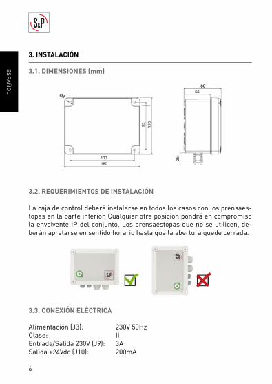
3.1. DIMENSIONES (mm)
3.2. REQUERIMIENTOS DE INSTALACIÓN
La caja de control deberá instalarse en todos los casos con los prensaes-
topas en la parte inferior. Cualquier otra posición pondrá en compromiso
la envolvente IP del conjunto. Los prensaestopas que no se utilicen, de-
berán apretarse en sentido horario hasta que la abertura quede cerrada.
3.3. CONEXIÓN ELÉCTRICA
Alimentación (J3): 230V 50Hz
Clase: II
Entrada/Salida 230V (J9): 3A
Salida +24Vdc (J10): 200mA
7
ES
PA
ÑO
L
4. PUESTA EN MARCHA
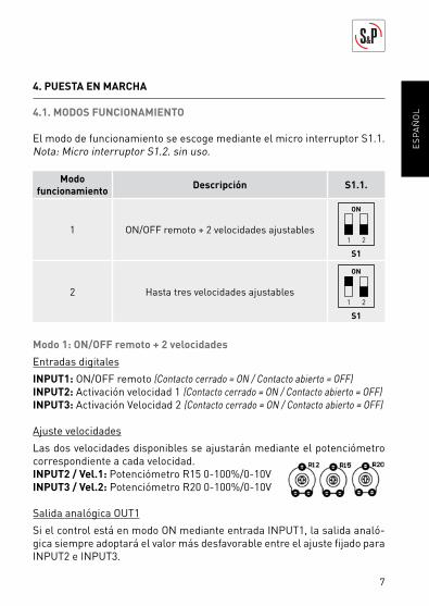
4.1. MODOS FUNCIONAMIENTO
El modo de funcionamiento se escoge mediante el micro interruptor S1.1.
Nota: Micro interruptor S1.2. sin uso.
Modo
funcionamientoDescripción S1.1.
1 ON/OFF remoto + 2 velocidades ajustables1 2
ON
S1
2 Hasta tres velocidades ajustables1 2
ON
S1
Modo 1: ON/OFF remoto + 2 velocidades
Entradas digitales
INPUT1: ON/OFF remoto (Contacto cerrado = ON / Contacto abierto = OFF)
INPUT2: Activación velocidad 1 (Contacto cerrado = ON / Contacto abierto = OFF)
INPUT3: Activación Velocidad 2 (Contacto cerrado = ON / Contacto abierto = OFF)
Ajuste velocidades
Las dos velocidades disponibles se ajustarán mediante el potenciómetro
correspondiente a cada velocidad.
INPUT2 / Vel.1: Potenciómetro R15 0-100%/0-10V
INPUT3 / Vel.2: Potenciómetro R20 0-100%/0-10V
Salida analógica OUT1
Si el control está en modo ON mediante entrada INPUT1, la salida analó-
gica siempre adoptará el valor más desfavorable entre el ajuste fi jado para
INPUT2 e INPUT3.
8
ES
PA
ÑO
L
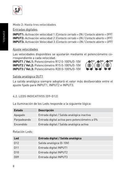
Modo 2: Hasta tres velocidades
Entradas digitales
INPUT1: Activación velocidad 1 (Contacto cerrado = ON / Contacto abierto = OFF)
INPUT2: Activación velocidad 2 (Contacto cerrado = ON / Contacto abierto = OFF)
INPUT3: Activación Velocidad 3 (Contacto cerrado = ON / Contacto abierto = OFF)
Ajuste velocidades
Las velocidades disponibles se ajustarán mediante el potenciómetro co-
rrespondiente a cada velocidad.
INPUT1 / Vel.1: Potenciómetro R12 0-100%/0-10V
INPUT2 / Vel.2: Potenciómetro R15 0-100%/0-10V
INPUT3 / Vel.3: Potenciómetro R20 0-100%/0-10V
Salida analógica OUT1
La salida analógica siempre adoptará el valor más desfavorable entre el
ajuste fi jado para INPUT1, INPUT2 e INPUT3.
4.2. LEDS INDICATIVOS (D9-D12)
La iluminación de los Leds responde a la siguiente lógica:
Estado Descripción
Apagado Entrada digital / Salida analógica inactiva
Parpadeando Entrada digital activa pero potenciómetro a 0%
Encendido Entrada digital / Salida analógica activa
Relación Leds:
Led Entrada digital / Salida analógica
D12 Salida analógica (0-10V)
D11 Entrada digital INPUT1
D10 Entrada digital INPUT2
D09 Entrada digital INPUT3
9
ES
PA
ÑO
L
4.3. SALIDA 230V (J9)
Salida 230V50Hz controlada mediante el interruptor lateral manual es-
pecialmente pensado para alimentar el ventilador ECOWATT con motor
ECtechnology.
4.4. SALIDA +24VDC (J10)
Disponible para alimentar un detector de presencia, reloj horario o sonda
con salida del tipo libre potencial a combinar con cualquiera de las entra-
das digitales INPUT1, INPUT2 o INPUT3.
5. MANTENIMIENTO
Antes de manipular el controlador, asegúrese de que está desconectado
de la red, aunque ya esté parado y de que nadie pueda ponerlo en marcha
durante la intervención.
Es necesaria una inspección regular del aparato. La frecuencia de la
misma, debe ser en función de las condiciones de trabajo para evitar la
acumulación de suciedad que podría entrañar riesgos y acortaría sensi-
blemente la vida del mismo.
En todos los trabajos de mantenimiento y reparación, deben observarse
las normas de seguridad vigente en cada país.
6. GESTIÓN RESIDUOS
La normativa de la CEE y el compromiso que debemos adquirir con las
futuras generaciones, nos obligan al reciclado de materiales, le rogamos
que no olvide depositar todos los elementos sobrantes del embalaje en los
correspondientes contenedores de reciclaje, así como de llevar los apara-
tos sustituidos al Gestor de Residuos más próximo.
10
ES
PA
ÑO
L
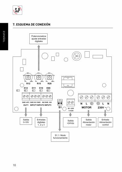
7. ESQUEMA DE CONEXIÓN

11
EN
GL
ISH
ÍNDICE
1. GENERAL ............................................................................................... 12
1.1. Warnings ......................................................................................... 12
1.2. Safety regulations and “CE” marking ............................................. 12
1.3. Reception and storage .................................................................... 13
2. PRODUCT PRESENTATION .................................................................... 13
3. INSTALLATION ....................................................................................... 14
3.1. Dimensions .................................................................................... 14
3.2. Installation requirements ............................................................... 14
3.3. Electrical supply ............................................................................. 14
4. START UP ............................................................................................... 15
4.1. Operating modes ............................................................................ 15
4.2. Leds indicators (D9-D12) ................................................................ 16
4.3. 230V output (J9) .............................................................................. 17
4.4. +24Vdc output (J10) ......................................................................... 17
5. MAINTENANCE ...................................................................................... 17
6. WASTE MANAGEMENT .......................................................................... 17
7. WIRING DIAGRAM .................................................................................. 18
ENGLISH
12
EN
GL
ISH
1. GENERAL
Thank you for purchasing this appliance. It has been manufactured in full
compliance with applicable safety regulations and EU standards.
Please read this instruction book carefully, as it contains important in-
formation for your safety during the installation, use and maintenance if
this product. Keep it at hand for future reference. Please check that the
appliance is in perfect condition when you unpack it, as all factory defects
are covered by the S&P guarantee.
1.1. WARNINGS
This manual contains all the information for all exposed, in order to pre-
vent possible damage to people and / or things, because of a defective
handling or maintenance. All maintenance interventions (ordinary and
extraordinary) must be carried out with the device off and disconnected
power supply. Before supplying power to the terminal, check that the line
voltage corresponds to that indicated on the nameplate of the unit.
1.2. SAFETY REGULATIONS AND “CE” MARKING
S&P technicians are fi rmly committed to research and development of ever
more effi cient products and in compliance with current safety regulations.
The instructions and recommendations given below refl ect current regu-
lations, principally regarding safety, and therefore are based on complian-
ce with general regulations. Therefore, we recommend all people exposed
to hazards to strictly follow the safety regulations in force in your country.
S&P will not be held liable for any possible harm or damage caused by non
compliance with the safety regulations, as well as caused by modifying
the product.
The CE mark and the corresponding declaration of conformity are proof of
the product’s conformity with current EU regulations.
13
EN
GL
ISH
1.3. RECEPTION AND STORAGE
When receiving the device, the unit will be unpacking and check the inte-
grity, any fault may be indicative of damage. It will check and verify that no
missing items.
The product should be kept away from weather inclement and spaces
where it can receive hits during transport and storage.
• Accepted temperature: -20°C to +60°C
• Permissible relative humidity: 30 to 95% without condensation
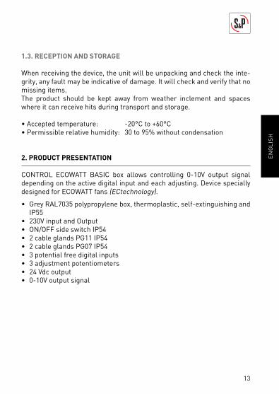
2. PRODUCT PRESENTATION
CONTROL ECOWATT BASIC box allows controlling 0-10V output signal
depending on the active digital input and each adjusting. Device specially
designed for ECOWATT fans (ECtechnology).
• Grey RAL7035 polypropylene box, thermoplastic, self-extinguishing and
IP55
• 230V input and Output
• ON/OFF side switch IP54
• 2 cable glands PG11 IP54
• 2 cable glands PG07 IP54
• 3 potential free digital inputs
• 3 adjustment potentiometers
• 24 Vdc output
• 0-10V output signal
14
EN
GL
ISH
3. INSTALLATION
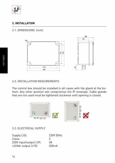
3.1. DIMENSIONS (mm)
3.2. INSTALLATION REQUIREMENTS
The control box should be installed in all cases with the gland at the bo-
ttom. Any other position will compromise the IP envelope. Cable glands
that are not used must be tightened clockwise until opening is closed.
3.3. ELECTRICAL SUPPLY
Supply (J3): 230V 50Hz
Class: II
230V input/output (J9): 3A
+24Vdc output (J10): 200mA
15
EN
GL
ISH
4. START UP
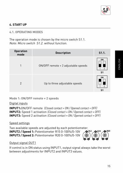
4.1. OPERATING MODES
The operation mode is chosen by the micro switch S1.1.
Note: Micro switch S1.2. without function.
Operation
modeDescription S1.1.
1 ON/OFF remote + 2 adjustable speeds1 2
ON
S1
2 Up to three adjustable speeds1 2
ON
S1
Mode 1: ON/OFF remote + 2 speeds
Digital inputs
INPUT1:ON/OFF remote (Closed contact = ON / Opened contact = OFF)
INPUT2: Speed 1 activation (Closed contact = ON / Opened contact = OFF)
INPUT3: Speed 2 activation (Closed contact = ON / Opened contact = OFF)
Speed settings
Two available speeds are adjusted by each potentiometer.
INPUT2 / Speed 1: Potentiometer R15 0-100%/0-10V
INPUT3 / Speed 2: Potentiometer R20 0-100%/0-10V
Output signal OUT1
If control is in ON status using INPUT1, output signal always take the worst
between adjustments for INPUT2 and INPUT3 values.
16
EN
GL
ISH
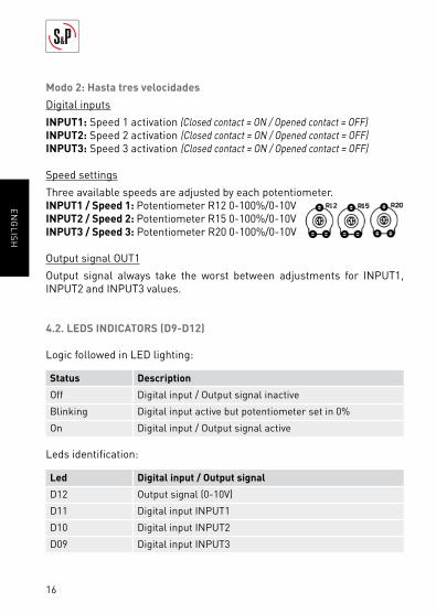
Modo 2: Hasta tres velocidades
Digital inputs
INPUT1: Speed 1 activation (Closed contact = ON / Opened contact = OFF)
INPUT2: Speed 2 activation (Closed contact = ON / Opened contact = OFF)
INPUT3: Speed 3 activation (Closed contact = ON / Opened contact = OFF)
Speed settings
Three available speeds are adjusted by each potentiometer.
INPUT1 / Speed 1: Potentiometer R12 0-100%/0-10V
INPUT2 / Speed 2: Potentiometer R15 0-100%/0-10V
INPUT3 / Speed 3: Potentiometer R20 0-100%/0-10V
Output signal OUT1
Output signal always take the worst between adjustments for INPUT1,
INPUT2 and INPUT3 values.
4.2. LEDS INDICATORS (D9-D12)
Logic followed in LED lighting:
Status Description
Off Digital input / Output signal inactive
Blinking Digital input active but potentiometer set in 0%
On Digital input / Output signal active
Leds identifi cation:
Led Digital input / Output signal
D12 Output signal (0-10V)
D11 Digital input INPUT1
D10 Digital input INPUT2
D09 Digital input INPUT3
17
EN
GL
ISH
4.3. 230V OUTPUT (J9)
230V50H output controlled by manual side switch specially designed to
power ECOWATT fans with ECtechnology motor.
4.4. +24VDC OUTPUT (J10)
Available to supply a presence detector, timer or sensor with free voltage
output to be combined with any digital input INPUT1, INPUT2 or INPUT3.
5. MAINTENANCE
Before manipulating the fan, make sure it is disconnected from the mains
supply even if it has previously been switched off.
Prevent the possibility of anyone else connecting it while it is being ma-
nipulated.
Fan unit must be regularly inspected. These inspections should be carried
out bearing in mind the machine’s working conditions, in order to avoid
dirt or dust accumulating that could be dangerous and perceptibly shorten
the life expectancy.
All maintenance and repair work should be carried out in strict compliance
with each country’s current safety regulations.
6. WASTE MANAGEMENT
EEC standard, together with the responsibility we should assume with fu-
ture generations in mind, oblige us to recycle all the materials we can.
Therefore, please deposit all left-over material and packaging in their co-
rresponding recycling containers and hand in the replaced machines to the
nearest handler of this type of waste product.
18
EN
GL
ISH
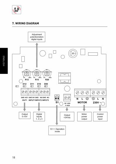
7. WIRING DIAGRAM

19
FR
AN
ÇA
IS
SOMMAIRE
1. GENERALITÉS ........................................................................................ 20
1.1. Normes generales .......................................................................... 20
1.2. Normes de sécurité et marquage “CE” .......................................... 20
1.3. Réception et stockage .................................................................... 21
2. PRESENTATION PRODUIT ..................................................................... 21
3. INSTALLATION ....................................................................................... 22
3.1. Dimensions (mm)............................................................................ 22
3.2. Exigences d’installation .................................................................. 22
3.3. Branchement électrique ................................................................. 22
4. MISE EN MARCHE .................................................................................. 23
4.1. Modes de fonctionnement .............................................................. 23
4.2. Sortie 230V (J9) ............................................................................... 24
4.3. Sortie +24Vdc (J10) ......................................................................... 25
4.4. Sortie +24Vdc (J10) ......................................................................... 25
5. MAINTENANCE ...................................................................................... 25
6. RECYCLAGE............................................................................................ 25
7. SCHÉMA DE BRANCHEMENT ............................................................... 26
FRANÇAIS
20
FR
AN
ÇA
IS
1. GÉNÉRALITÉS
Avant d’installer et d’utiliser ce produit, lire attentivement ces instructions
qui contiennent d’importantes indications pour votre sécurité et celle des
utilisateurs, pendant l’installation, l’utilisation et l’entretien de ce produit.
Une fois l’installation terminée, laisser ce manuel à la disposition de l’uti-
lisateur fi nal.
1.1. NORMES GÉNÉRALES
Les dispositifs de protection ne doivent pas être enlevés sauf en cas d’ab-
solue nécessité.
Dans ce cas, des mesures appropriées seront immédiatement adoptées
pour signaler explicitement le danger. Dés que possible, les dispositifs de
protection doivent impérativement être rétablis.
Toutes les interventions de maintenance (régulières ou occasionnelles) se
feront alimentation électrique coupée.
Avant de brancher le câble d’alimentation électrique de l’appareil, il con-
vient de s’assurer que la tension est conforme à celle indiquée sur le pro-
duit.
1.2. NORMES DE SÉCURITÉ ET MARQUAGE « CE »
Toujours à la pointe de l’innovation, nos équipes d’ingénieurs n’ont de ces-
se de développer des produits de plus en plus performants conformes aux
normes de sécurité en vigueur.
Les normes et conseils, contenus dans ce manuel, se réfèrent aux normes
standards en application et par conséquent, sont basés sur la conformité
avec les normes générales.
Ainsi, nous conseillons vivement à toutes les personnes concernées
d’appliquer les règles en vigueur dans leurs pays en matière de prévention
d’accidents.
La responsabilité de S&P ne saurait être engagée pour d’éventuels dom-
mages corporels et/ou matériels causés lorsque les consignes de sécurité
n’ont pas été respectées ou suite à une modifi cation du produit.

21
FR
AN
ÇA
IS
Le marquage CE ainsi que les déclarations de conformité certifi ent la con-
formité aux normes européennes en vigueur.
1.3. RÉCEPTION ET STOCKAGE
Dès la réception du produit, le sortir de son emballage et vérifi er son état
général. Contrôler et vérifi er la présence de tous les éléments.
Le produit doit être placé à l’abri des intempéries et protégé contre les
chocs aussi bien lors de son transport que lors de son stockage.
• Température admissible: -20°C à +60°C
• Humidité relative admissible: 30 à 95% sans condensation
2. PRESENTATION PRODUIT
Le boitier CONTROL ECOWATT BASIC permet de contrôler un signal de
sortie analogique 0-10V en fonction des entrées digitales actives et le ré-
glage de chacune d’elles. Il a été spécialement conçu pour piloter les ven-
tilateurs du type ECOWATT (ECtechnology).
• Boitier en polypropylène gris RAL 7035, en plastique auto-extinguible
et IP55
• Entrée et sortie 230V
• Interrupteur latéral IP54 MARCHE/ARRÊT
• 2 presse-étoupes PG11 IP54
• 2 presse-étoupes PG07 IP54
• 3 entrées digitales libres de potentiel
• 3 potentiomètres de réglage
• Sortie 24Vdc pour alimenter une sonde ou un dispositif émetteur
• Sortie analogique 0-10V
22
FR
AN
ÇA
IS
3. INSTALLATION
3.1. DIMENSIONS (mm)
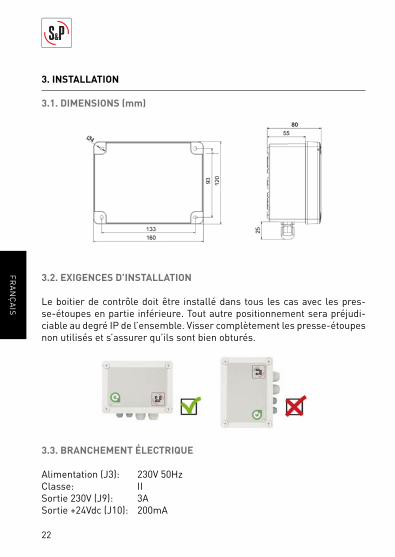
3.2. EXIGENCES D’INSTALLATION
Le boitier de contrôle doit être installé dans tous les cas avec les pres-
se-étoupes en partie inférieure. Tout autre positionnement sera préjudi-
ciable au degré IP de l’ensemble. Visser complètement les presse-étoupes
non utilisés et s’assurer qu’ils sont bien obturés.
3.3. BRANCHEMENT ÉLECTRIQUE
Alimentation (J3): 230V 50Hz
Classe: II
Sortie 230V (J9): 3A
Sortie +24Vdc (J10): 200mA
23
FR
AN
ÇA
IS
4. MISE EN MARCHE
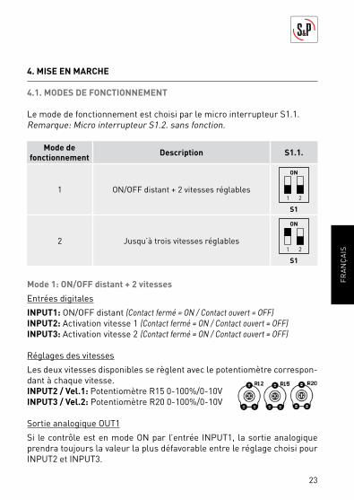
4.1. MODES DE FONCTIONNEMENT
Le mode de fonctionnement est choisi par le micro interrupteur S1.1.
Remarque: Micro interrupteur S1.2. sans fonction.
Mode de
fonctionnementDescription S1.1.
1 ON/OFF distant + 2 vitesses réglables 1 2
ON
S1
2 Jusqu’à trois vitesses réglables1 2
ON
S1
Mode 1: ON/OFF distant + 2 vitesses
Entrées digitales
INPUT1: ON/OFF distant (Contact fermé = ON / Contact ouvert = OFF)
INPUT2: Activation vitesse 1 (Contact fermé = ON / Contact ouvert = OFF)
INPUT3: Activation vitesse 2 (Contact fermé = ON / Contact ouvert = OFF)
Réglages des vitesses
Les deux vitesses disponibles se règlent avec le potentiomètre correspon-
dant à chaque vitesse.
INPUT2 / Vel.1: Potentiomètre R15 0-100%/0-10V
INPUT3 / Vel.2: Potentiomètre R20 0-100%/0-10V
Sortie analogique OUT1
Si le contrôle est en mode ON par l’entrée INPUT1, la sortie analogique
prendra toujours la valeur la plus défavorable entre le réglage choisi pour
INPUT2 et INPUT3.

24
FR
AN
ÇA
IS
Mode 2: Jusqu’à trois vitesses
Entrées digitales
INPUT1: Activation vitesse 1 (Contact fermé = ON / Contact ouvert = OFF)
INPUT2: Activation vitesse 2 (Contact fermé = ON / Contact ouvert = OFF)
INPUT3: Activation vitesse 3 (Contact fermé = ON / Contact ouvert = OFF)
Réglages des vitesses
Les vitesses disponibles se règlent avec le potentiomètre correspondant
à chaque vitesse.
INPUT1 / Vel.1: Potentiomètre R12 0-100%/0-10V
INPUT2 / Vel.2: Potentiomètre R15 0-100%/0-10V
INPUT3 / Vel.3: Potentiomètre R20 0-100%/0-10V
Sortie analogique OUT1
La sortie analogique prendra toujours la valeur la plus défavorable entre le
réglage choisi pour INPUT1, INPUT2 et INPUT3.
4.2. LEDS INDICATIVES (D9-D12)
L’illumination des led correspond à la logique suivante:
État Description
Éteint Entrée digitale / Sortie analogique inactive
Clignoter Entrée digitale active par potentiomètre à 0%
Allumer Entrée digitale / Sortie analogique active
Relation Leds:
Led Entrée digitale / Sortie analogique
D12 Sortie analogique (0-10V)
D11 Entrée digitale INPUT1
D10 Entrée digitale INPUT2
D09 Entrée digitale INPUT3
25
FR
AN
ÇA
IS
4.3. SORTIE 230V (J9)
Sortie 230V50Hz contrôlée par l’interrupteur latéral manuel prévu spécia-
lement pour alimenter le ventilateur ECOWATT avec moteur ECtechnology.
4.4. SORTIE +24VDC (J10)
Disponible pour alimenter un détecteur de présence, une horloge ou une
sonde avec sortie libre de potentiel pour se raccorder avec une des en-
trées digitales INPUT1, INPUT2 o INPUT3.
5. MAINTENANCE
Avant de manipuler le ventilateur, vérifi er qu’il est bien déconnecté du ré-
seau même s’il est déjà arrêté et s’assurer que personne ne peut le reme-
ttre en marche pendant l’intervention.
Il est nécessaire d’inspecter régulièrement l’appareil. La fréquence des
contrôles doit être défi nie en fonction des conditions de travail pour éviter
l’accumulation de saleté dans les hélices, les roues, les moteurs et les
grilles qui pourraient représenter un risque et réduirait sensiblement la
durée de vie de l’appareil.
Lors des opérations de nettoyage veiller à ne pas déséquilibrer l’hélice
ou la roue.
Pour tous les travaux de maintenance et réparation observer les règles de
sécurité en vigueur dans chaque pays.
6. RECYCLAGE
La norme CEE et l’engagement que nous avons pris envers les généra-
tions futures nous obligent à recycler les matériaux ; nous vous serions
reconnaissants de ne pas oublier de déposer tous les éléments de l’emba-
llage non utilisés dans les conteneurs de recyclage correspondant, ainsi
que de transporter les appareils remplacés vers le centre de Gestion des
Déchets le plus proche.
26
FR
AN
ÇA
IS
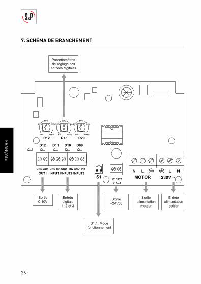
7. SCHÉMA DE BRANCHEMENT
27
NE
DE
RL
AN
DS
INHOUD
1. ALGEMEEN ............................................................................................. 28
1.1. Waarschuwingen ............................................................................. 28
1.2. Veiligheidsvoorschriften en CE-markering .................................... 28
1.3. Ontvangst en opslag ....................................................................... 29
2. PRODUCTPRESENTATIE ........................................................................ 29
3. INSTALLATIE .......................................................................................... 30
3.1. Afmetingen ..................................................................................... 30
3.2. Installatie-eisen .............................................................................. 30
3.3. Elektrische voeding ........................................................................ 14
4. OPSTARTEN ........................................................................................... 15
4.1. Bedrijfsstanden ............................................................................... 15
4.2. Led-indicatoren (D9-D12) ............................................................... 16
4.3. 230 V-output (J9) ............................................................................ 17
4.4. +24 Vdc-output (J10) ....................................................................... 17
5. ONDERHOUD ......................................................................................... 17
6. AFVALBEHEER ....................................................................................... 17
7. BEDRADINGSSCHEMA .......................................................................... 18
NEDERLANDS
28
NE
DE
RL
AN
DS
1. ALGEMEEN
Hartelijk dank voor de aankoop van dit product. Dit product is gemaakt
volgens alle van toepassing zijnde veiligheidsvoorschriften en EU-normen.
Lees deze handleiding zorgvuldig door. Hierin staat informatie die be-
langrijk is voor uw veiligheid tijdens de installatie, het gebruik en het
onderhoud aan dit product. Bewaar deze handleiding voor later gebruik.
Controleer of het product bij het uitpakken in perfecte staat is, omdat alle
fabricagefouten onder de garantie van S&P vallen.
1.1. WAARSCHUWINGEN
Deze handleiding bevat informatie om mogelijk letsel bij personen en/of
schade aan zaken als gevolg van onjuiste hantering of onjuist onderhoud
aan het apparaat te voorkomen. Al het onderhoud (regulier en uitzonder-
lijk) moet uitgevoerd worden terwijl het apparaat uitgeschakeld en de voe-
ding losgekoppeld is. Voordat de voedingsspanning wordt aangesloten op
de aansluitklemmen, moet u controleren of de netspanning overeenkomt
met de aanduiding op het typeplaatje.
1.2. VEILIGHEIDSVOORSCHRIFTEN EN CE-MARKERING
De technici van S&P werken hard aan de ontwikkeling van steeds effi ciën-
tere producten die voldoen aan de laatste veiligheidsvoorschriften.
Onderstaande instructies en aanbevelingen zijn een afspiegeling van de
huidige voorschriften, met name voorschriften ten aanzien van veiligheid,
en zijn daarom gebaseerd op naleving van algemene voorschriften. Men-
sen die blootgesteld worden aan risico’s, dienen daarom bij voorkeur de
veiligheidsvoorschriften na te leven die binnen uw land van toepassing zijn.
S&P kan niet aansprakelijk gesteld worden voor mogelijke schade of mo-
gelijk letsel als gevolg van het niet naleven van de veiligheidsvoorschriften
of door het aanbrengen van wijzigingen aan het product.
De CE-markering en de desbetreffende conformiteitsverklaring vormen
een bewijs van de conformiteit van het product met de huidige EU-voor-
schriften.

29
NE
DE
RL
AN
DS
1.3. ONTVANGST EN OPSLAG
Bij ontvangst moet het apparaat uit de verpakking genomen worden om te
controleren of alles in goede staat is. Eventuele tekortkomingen kunnen
een aanwijzing zijn dat het apparaat beschadigd is. Controleer of er geen
onderdelen ontbreken.
Het product mag niet blootgesteld worden aan weersinvloeden en mag
niet in een ruimte of vervoermiddel worden geplaatst waar het tijdens op-
slag resp. transport beschadigd kan raken.
• Toelaatbare temperatuur: -20°C tot +60°C
• Toelaatbare relatieve luchtvochtigheid: 30 tot 95% zonder
condensvorming
2. PRODUCT PRESENTATIE
Met de CONTROL ECOWATT BASIC kan een uitgangssignaal van 0-10 V
aangestuurd worden. Dit is afhankelijk van een actief digitaal ingangssig-
naal en de instelling van een potentiometer. Apparaat specifi ek ontwikkeld
voor ECOWATT-ventilatoren (ECtechnology).
• Grijze (RAL 7035) polypropyleenbehuizing, thermoplastisch, zelfdovend
en IP55
• 230 V-input en –output
• AAN/UIT-schakelaar aan de zijkant IP54
• 2 kabelwartels PG11 IP54
• 2 kabelwartels PG07 IP54
• 3 potentiaalvrije digitale ingangen
• 3 instelbare potentiometers
• 24 Vdc-output voor voeding van sensor
• Outputsignaal 0-10 V
30
NE
DE
RL
AN
DS
3. INSTALLATIE
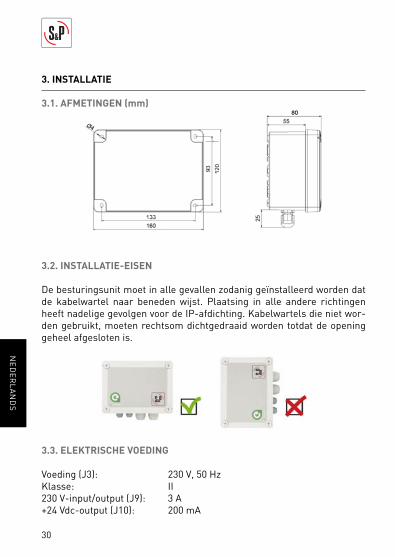
3.1. AFMETINGEN (mm)
3.2. INSTALLATIE-EISEN
De besturingsunit moet in alle gevallen zodanig geïnstalleerd worden dat
de kabelwartel naar beneden wijst. Plaatsing in alle andere richtingen
heeft nadelige gevolgen voor de IP-afdichting. Kabelwartels die niet wor-
den gebruikt, moeten rechtsom dichtgedraaid worden totdat de opening
geheel afgesloten is.
3.3. ELEKTRISCHE VOEDING
Voeding (J3): 230 V, 50 Hz
Klasse: II
230 V-input/output (J9): 3 A
+24 Vdc-output (J10): 200 mA
31
NE
DE
RL
AN
DS
4. OPSTARTEN
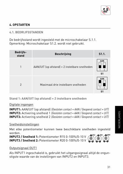
4.1. BEDRIJFSSTANDEN
De bedrijfsstand wordt ingesteld met de microschakelaar S.1.1.
Opmerking: Microschakelaar S1.2. wordt niet gebruikt.
Bedrijfs-
standBeschrijving S1.1.
1 AAN/UIT (op afstand) + 2 instelbare snelheden1 2
AAN
S1
2 Maximaal drie instelbare snelheden1 2
AAN
S1
Stand 1: AAN/UIT (op afstand) + 2 instelbare snelheden
Digitale ingangen
INPUT1: AAN/UIT (op afstand) (Gesloten contact = AAN / Geopend contact = UIT)
INPUT2: Activering snelheid 1 (Gesloten contact = AAN / Geopend contact = UIT)
INPUT3: Activering snelheid 2 (Gesloten contact = AAN / Geopend contact = UIT)
Snelheidsinstellingen
Met elke potentiometer kunnen twee beschikbare snelheden ingesteld
worden.
INPUT2 / Snelheid 1: Potentiometer R15 0-100%/0-10 V
INPUT3 / Snelheid 2: Potentiometer R20 0-100%/0-10 V
Outputsignaal OUT1
Als INPUT1 ingeschakeld is, gebruikt het uitgangssignaal altijd de ongun-
stigste waarde van de instellingen van INPUT2 en INPUT3.
32
NE
DE
RL
AN
DS
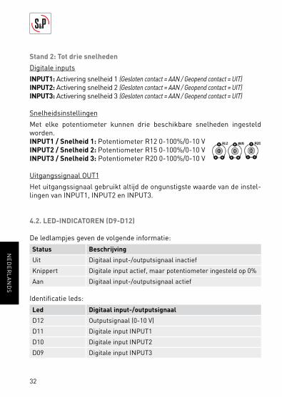
Stand 2: Tot drie snelheden
Digitale inputs
INPUT1: Activering snelheid 1 (Gesloten contact = AAN / Geopend contact = UIT)
INPUT2: Activering snelheid 2 (Gesloten contact = AAN / Geopend contact = UIT)
INPUT3: Activering snelheid 3 (Gesloten contact = AAN / Geopend contact = UIT)
Snelheidsinstellingen
Met elke potentiometer kunnen drie beschikbare snelheden ingesteld
worden.
INPUT1 / Snelheid 1: Potentiometer R12 0-100%/0-10 V
INPUT2 / Snelheid 2: Potentiometer R15 0-100%/0-10 V
INPUT3 / Snelheid 3: Potentiometer R20 0-100%/0-10 V
Uitgangssignaal OUT1
Het uitgangssignaal gebruikt altijd de ongunstigste waarde van de instel-
lingen van INPUT1, INPUT2 en INPUT3.
4.2. LED-INDICATOREN (D9-D12)
De ledlampjes geven de volgende informatie:
Status Beschrijving
Uit Digitaal input-/outputsignaal inactief
Knippert Digitale input actief, maar potentiometer ingesteld op 0%
Aan Digitaal input-/outputsignaal actief
Identifi catie leds:
Led Digitaal input-/outputsignaal
D12 Outputsignaal (0-10 V)
D11 Digitale input INPUT1
D10 Digitale input INPUT2
D09 Digitale input INPUT3
33
NE
DE
RL
AN
DS
4.3. 230 V-OUTPUT (J9)
230V/50Hz-output wordt aangestuurd met de schakelaar aan de zijkant en
is specifi ek bedoeld voor het aandrijven van ECOWATT-ventilatoren met
een ECtechnology-motor.
4.4. +24 VDC-UITGANG (J10)
Dit outputssignaal dient voor het aansluiten van een aanwezigheidsdetector,
een tijdklok of sensor met spanningsvrije uitgang. Deze kan gecombineerd
worden met een of meer digitale ingangen INPUT1, INPUT2 of INPUT3.
5. ONDERHOUD
Voordat u de ventilator o pent, dient u deze los te koppelen van de netspan-
ning, ook als de ventilator eerder al uitgeschakeld is.
Voorkom dat iemand anders de ventilator kan aansluiten terwijl hieraan
gewerkt wordt.
De ventilatoren moeten regelmatig geïnspecteerd worden. Deze inspec-
ties moeten uitgevoerd worden met inachtneming van de bedrijfsomstan-
digheden van de machine, zodat vuil en stof zich niet kunnen ophopen.
Ophoping van vuil of stof kan gevaarlijk zijn en kan de levensduur van het
apparaat aanzienlijk verkorten.
Alle onderhouds- en reparatiewerkzaamheden moeten uitgevoerd worden
met inachtneming van de actuele veiligheidsvoorschriften van elk land.
6. AFVALBEHEER
De Europese normen, in combinatie met de verantwoordelijkheid die we
hebben ten aanzien van de toekomstige generaties, verplichten ons tot het
zo veel mogelijk hergebruiken van alle materialen. Werp daarom alle over-
bodige materialen en verpakkingen in de desbetreffende recyclingcontai-
ners en lever afgedankte machines in bij de dichtstbijzijnde verwerker van
dit soort afval.
34
NE
DE
RL
AN
DS
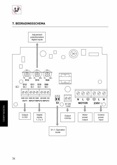
7. BEDRADINGSSCHEMA
35
CE
SK
Y
OBSAH
1. ÚVOD ......................................................................................................................................36
1.1. Upozornění ..................................................................................................................36
1.2. Bezpečnostní předpisy a CE označení ................................................................36
1.3. Dodání a uchování produktu.................................................................................37
2. POPIS PRODUKTU ..............................................................................................................37
3. Pokyny k instalaci ................................................................................................................38
3.1. Rozměry ........................................................................................................................38
3.2. Montáž ...........................................................................................................................38
3.3. Napájení ........................................................................................................................38
4. OVLÁDÁNÍ .............................................................................................................................39
4.1. Pracovní režimy ..........................................................................................................39
4.2. LED kontrolky (D9-D12) ...........................................................................................40
4.3. 230V výstup .................................................................................................................41
4.4. +24Vdc výstup (J10) ..................................................................................................41
5. ÚDRŽBA .................................................................................................................................41
6. NAKLÁDÁNÍ Z ODPADY ...................................................................................................41
7. SCHÉMA ZAPOJENÍ ...........................................................................................................42
CESKY
36
CE
SK
Y
1. ÚVOD
Děkujeme za výběr našich služeb při nákupu tohoto výrobku. Zakoupili jste
výrobek vysoké kvality vyrobený v plném souladu s bezpečnostními předpisy a
normami EU. Přečtěte si, prosím, tento návod pozorně, jelikož obsahuje důleži-
té informace pro Vaši bezpečnost během instalace, provozu a údržby tohoto
výrobku. Uchovejte tento návod pro budoucí použití. Prosím zkontrolujte, zda
je spotřebič po vybalení v perfektním stavu, jelikož na všechny výrobní vady se
vztahuje záruka S&P.
1.1. UPOZORNĚNÍ
Tento manuál obsahuje všechny potřebné informace nutné pro předejití újmě
na zdraví lidí, nebo vzniku materiální škody vlivem nesprávného zacházení a
údržby zařízení. V průběhu oprav či jakýchkoli jiných zásahů do zařízení musí
být zařízení odpojeno od zdroje elektrického napětí. Před připojením zařízení
k síti zkontrolujte, zda hodnoty napětí v přípojce odpovídají hodnotám uve-
deným na štítku produktu.
1.2. BEZPEČNOSTNÍ PŘEDPISY A CE OZNAČENÍ
S&P technici jsou pevně odhodláni neustále pracovat na zlepšování pro-
duktu tak aby odpovídal všem platným bezpečnostním předpisům. Pravidla
a doporučení uvedená níže plně vyhovují platným předpisům týkajících se
bezpečnosti, zejména na základě plnění předpisů obecné povahy. Proto do-
poručujeme, aby všichni lidé vystavení riziku striktně dodržovali preventivní
bezpečnostní a předpisy platné v jejich zemi. S&P nenese odpovědnost za
újmu na zdraví nebo na majetku v důsledku nedodržení bezpečnostních pře-
dpisů nebo z neoprávněné úpravy výrobku. Označení CE a odpovídající pro-
hlášení o shodě potvrzuje shodu s platnými normami Evropské unie. V případě
objasnění jakýchkoli dotazů ohledně S&P produktů, neváhejte se obrátit na
poprodejní servisní sít, buď ve Španělsku, nebo ve své zemi. Jejich umístění
najdete na webových stránkách: www.solerpalau.com

37
CE
SK
Y
1.3. DODÁNÍ A UCHOVÁNÍ PRODUKTU
Při přebíráni zařízeni zkontrolujte úplnost a stav produktu, aby došlo k včasné-
mu odhalení jakýchkoliv závad nebo chybějících dílů.
Zařízení by mělo být uchovávání déle od nepříznivých vlivů prostředí a zabale-
no tak, aby nedošlo v průběhu transportu k fyzického poškození.
• Přijatelná teplota : -20°C to +60°C
• Přípustná relativní vlhkost : od 30 do 90% bez kondenzace
2. POPIS PRODUKTU
CONTROL ECOWATT BASIC umožnuje řídit 0-10 voltový výstupní signál v zá-
vislosti na digitálním vstupu. Regulátor je navržen speciálně pro ventilátory
ECOWATT.
• Plastový kryt (tepelně odolný, barva šedá RAL7035),
• 230V vstup a výstup,
• přepínač zapnou/vypnout, IP54,
• dvě průchodky PG11/IP54,
• dvě průchodky PG07/IP54,
• 3 digitální vstupy,
• 3 přizpůsobitelné potenciometry,
• 24 Vdc výstup,
• 0-10V výstupní signál.

38
CE
SK
Y
3. POKYNY K INSTALACI
3.1. ROZMĚRY (mm)
3.2. MONTÁŽ
Zařízení by mělo být umístěno tak, aby průchodky pro elektrické kabely směřo-
valy směrem k zemi.
Jakékoliv jiné ustavení zařízení může mýt za následek poškození pláště kabelů.
Nepoužívané průchodky musí být uzavřeny (k uzavření dojde otáčením prů-
chodky proti směru hodinových ručiček).
3.3. NAPÁJENÍ
• Zdroj (J3) – 230V 50Hz,
• Třída – II,
• 230V vstup/výstup(J9) – 3A,
• +24Vdc výstup (J10) – 200 mA.
39
CE
SK
Y
4. OVLÁDÁNÍ
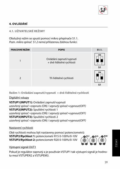
4.1. UŽIVATELSKÉ REŽIMY
Obslužný režim se spustí pomocí mikro přepínače S1.1.
Pozn. mikro spínač S1.2 nemá přiřazenou žádnou funkci.
PRACOVNÍ REŽIM POPIS S1.1.
1Ovládání zapnutí/vypnutí
+ dvě říditelné rychlosti 1 2
ON
S1
2 Tři řiditelné rychlosti1 2
ON
S1
Režim 1: Ovládání zapnutí/vypnutí + dvě říditelné rychlosti
Digitální vstupy
VSTUP1(INPUT1): Ovládání zapnutí/vypnutí
uzavřený spínač =zapnuto (ON) / sepnutý spínač=vypnout(OFF)
VSTUP2(INPUT2): Spuštění rychlosti 1
uzavřený spínač =zapnuto (ON) / sepnutý spínač=vypnout(OFF)
VSTUP3(INPUT3): Spuštění rychlosti 2
uzavřený spínač =zapnuto (ON) / sepnutý spínač=vypnout(OFF)
Nastavení rychlosti
Obě rychlosti mohou být nastaveny pomocí potenciometrů:
VSTUP2/Rychlost 1: potenciometr R15 0-100%/0-10V
VSTUP3/Rychlost 2: potenciometr R20 0-100%/0-10V
Výstupní signál OUT1
Pokud je regulátor zapnutý a je používán VSTUP1 tak výstupní signál je hodno-
ta mezi VSTUPEN2 a VSTUPEM3.
40
CE
SK
Y
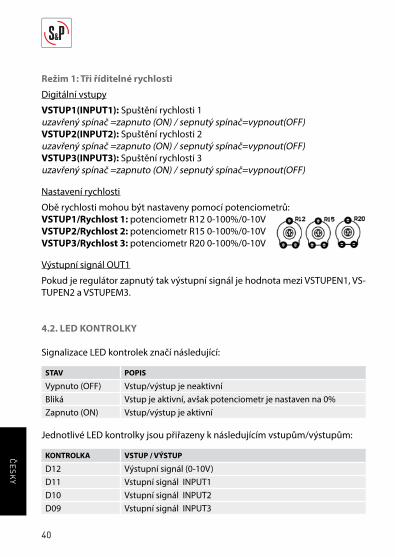
Režim 1: Tři říditelné rychlosti
Digitální vstupy
VSTUP1(INPUT1): Spuštění rychlosti 1
uzavřený spínač =zapnuto (ON) / sepnutý spínač=vypnout(OFF)VSTUP2(INPUT2): Spuštění rychlosti 2
uzavřený spínač =zapnuto (ON) / sepnutý spínač=vypnout(OFF)VSTUP3(INPUT3): Spuštění rychlosti 3
uzavřený spínač =zapnuto (ON) / sepnutý spínač=vypnout(OFF)
Nastavení rychlosti
Obě rychlosti mohou být nastaveny pomocí potenciometrů:
VSTUP1/Rychlost 1: potenciometr R12 0-100%/0-10V
VSTUP2/Rychlost 2: potenciometr R15 0-100%/0-10V
VSTUP3/Rychlost 3: potenciometr R20 0-100%/0-10V
Výstupní signál OUT1
Pokud je regulátor zapnutý tak výstupní signál je hodnota mezi VSTUPEN1, VS-
TUPEN2 a VSTUPEM3.
4.2. LED KONTROLKY
Signalizace LED kontrolek značí následující:
STAV POPIS
Vypnuto (OFF) Vstup/výstup je neaktivní
Bliká Vstup je aktivní, avšak potenciometr je nastaven na 0%
Zapnuto (ON) Vstup/výstup je aktivní
Jednotlivé LED kontrolky jsou přiřazeny k následujícím vstupům/výstupům:
KONTROLKA VSTUP / VÝSTUP
D12 Výstupní signál (0-10V)
D11 Vstupní signál INPUT1
D10 Vstupní signál INPUT2
D09 Vstupní signál INPUT3
41
CE
SK
Y
4.3. 230V VÝSTUP (J9)
230V 50Hz výstup ovládaný manuálním přepínačem je navržen speciálně pro
ventilátory Ecowatt s EC motory.
4.4. +24VDCVÝSTUP (J10)
Určen pro připojení detektoru pohybu, časovače nebo jakéhokoli jiného sen-
zoru vhodného pro připojení na vstupy 1,2 a 3.
5. ÚDRŽBA
Před manipulací s ventilátorem se ujistěte, zdali je zařízení odpojeno od zdroje
napětí a že je vypnuté. Předejděte tomu, aby druhou osobou nedošlo k zap-
nutí zařízení v průběhu manipulace s ním. Aby ventilátory pracovaly ve vhod-
ných podmínkách a nedocházelo ke zkracování životnosti produktu, je nutné
pravidelně provádět prohlídku zařízení a pokud nutno vyčistit a zbavit je od
naakumulovaného prachu. Všechny údržbové a opravářské práce musí být pro-
vedeny výhradně dle bezpečnostních předpisů platných ve vaší zemi.
6. NAKLÁDÁNÍ Z ODPADY
Právní předpisy EU a naše odpovědnost vůči budoucím generacím nás zavazují
k recyklaci používaných materiálů; nezapomeňte se zbavit všech nežádoucích
obalových materiálů na příslušných recyklačních místech a zbavte se zasta-
ralého zařízení na nejbližším místě nakládání s odpady.
42
CE
SK
Y
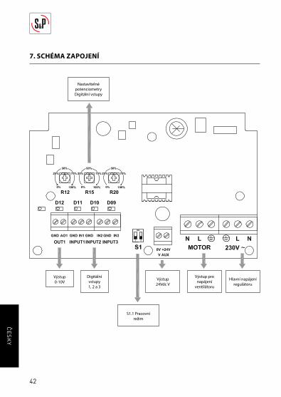
7. SCHÉMA ZAPOJENÍ
Hlavní napájení
regulátoru
Výstup pro
napájení
ventilátoru
Výstup
0-10VVýstup
24Vdc V
S1.1 Pracovní
režim
Digitální
vstupy
1, 2 a 3
Nastavitelné
potenciometry
Digitální vstupy


S&P SISTEMAS DE VENTILACIÓN, S.L.U.
C. Llevant, 4
Polígono Industrial Llevant
08150 Parets del Vallès
Barcelona - España
Tel. +34 93 571 93 00
Fax +34 93 571 93 01
www.solerpalau.com
Ref. 1441268 -01