05 .. .. .. 1232 - laip · 50 50 70 30 46 90 001 12 02 04 80 ... desviación circular entre k y d1...
TRANSCRIPT
... 05 .. .. .. CONO JIS BT 6339JIS BT 6399 TAPER12
32
3
100
CONO JIS BT 6339 JIS BT 6339 TAPER... 12 .. .. ..12
32
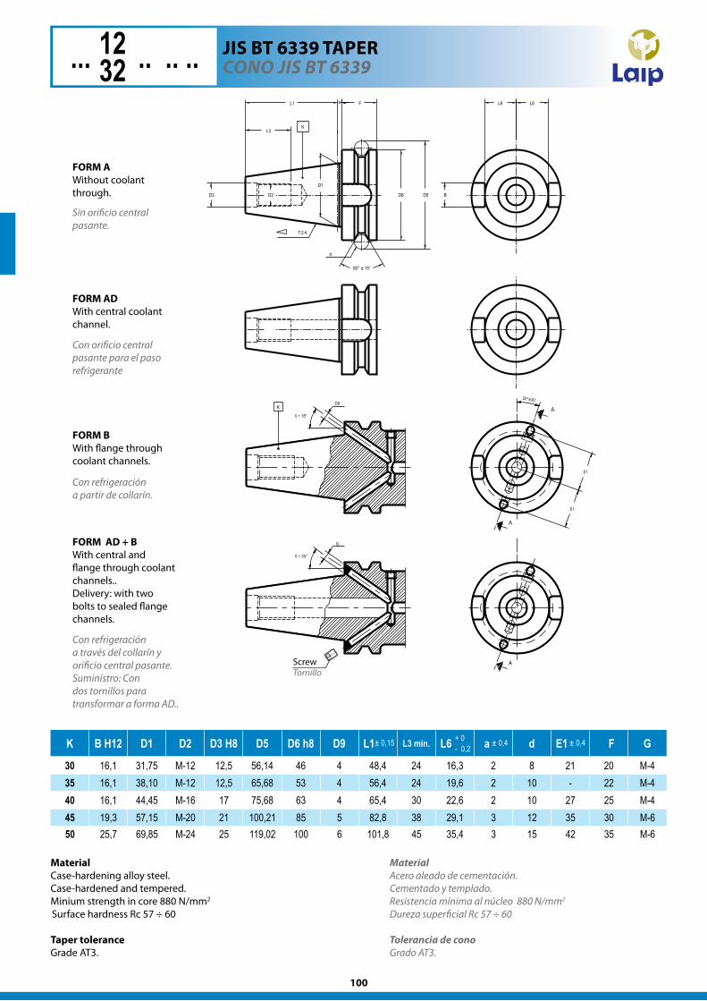
K B H12 D1 D2 D3 H8 D5 D6 h8 D9 L1 L3 min. L6 a d E1 F G
30 16,1 31,75 M-12 12,5 56,14 46 4 48,4 24 16,3 2 8 21 20 M-435 16,1 38,10 M-12 12,5 65,68 53 4 56,4 24 19,6 2 10 - 22 M-440 16,1 44,45 M-16 17 75,68 63 4 65,4 30 22,6 2 10 27 25 M-445 19,3 57,15 M-20 21 100,21 85 5 82,8 38 29,1 3 12 35 30 M-650 25,7 69,85 M-24 25 119,02 100 6 101,8 45 35,4 3 15 42 35 M-6
+ 0- 0,2
± 0,4± 0,15 ± 0,4
Sin orificio central pasante.
L6 L6
B
20°±30’
A
A
E1
E1
0 ÷ 35°
D9K
aL1
7:2 4
L3K
D3 D2
D1
D5
60° ± 15'
D6
d
F
A
0 ÷ 35°
G
Tornill o
The rest of the dimensions are according to MAS 403-BT
FORM AWithout coolant through.
FORM ADWith central through coolant channel.
FORM BWith flange through coolant channels.
FORM AD + BWith central and flange through coolant channels.Delivery:With two bolts to sealed flange channels. Screw
Tornillo
FORM AWithout coolant through.
Con orificio central pasante para el paso refrigerante
Con refrigeración a partir de collarín.
FORM AD + BWith central and flange through coolant channels..Delivery: with two bolts to sealed flange channels.
Con refrigeración a través del collarín y orificio central pasante.Suministro: Con dos tornillos para transformar a forma AD..
FORM BWith flange through coolant channels.
FORM ADWith central coolant channel.
MaterialCase-hardening alloy steel. Case-hardened and tempered. Minium strength in core 880 N/mm2
Surface hardness Rc 57 ÷ 60
Taper toleranceGrade AT3.
MaterialAcero aleado de cementación. Cementado y templado. Resistencia mínima al núcleo 880 N/mm2 Dureza superficial Rc 57 ÷ 60
Tolerancia de conoGrado AT3.
101
CONO JIS BT 6339 JIS BT 6339 TAPER... 12 .. .. ..12
32
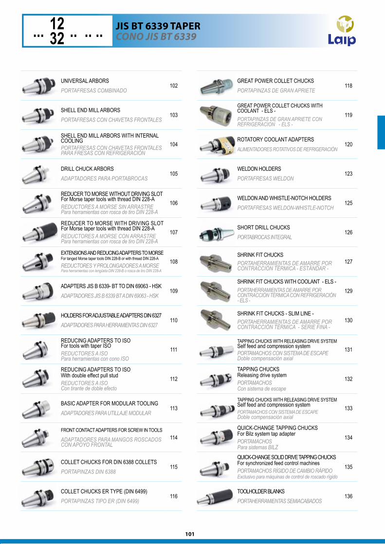
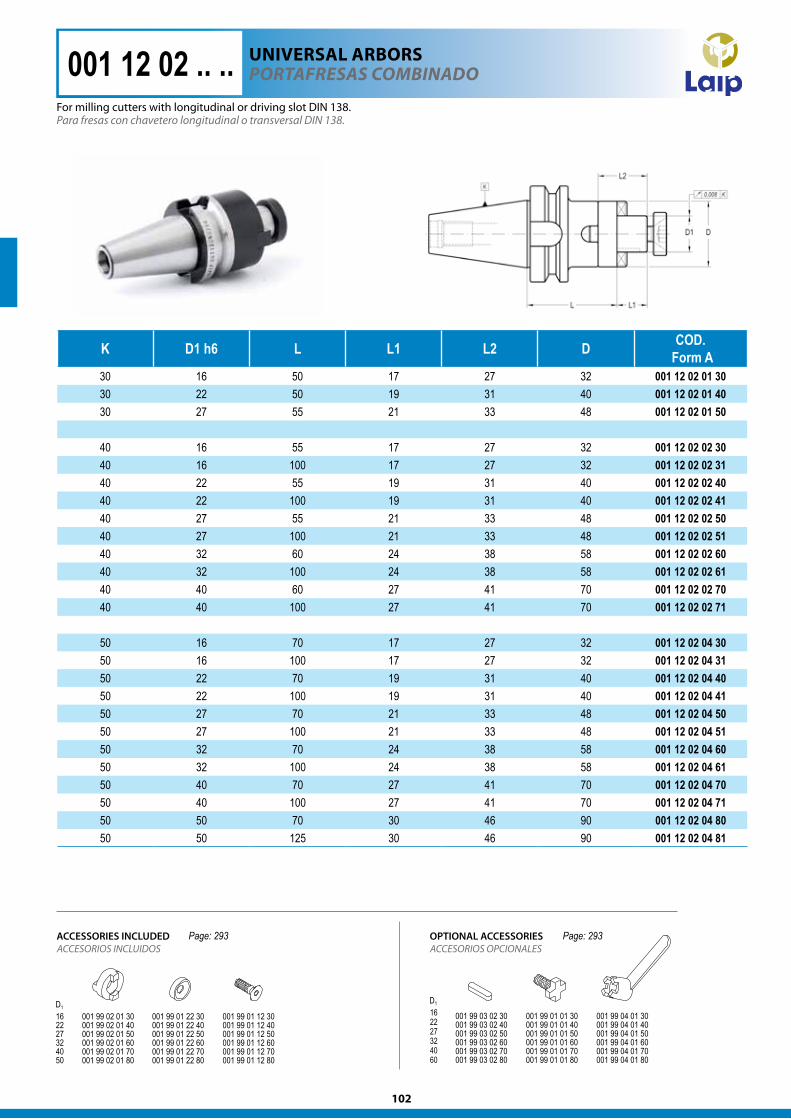
UNIVERSAL ARBORSPORTAFRESAS COMBINADO
102
SHELL END MILL ARBORSPORTAFRESAS CON CHAVETAS FRONTALES
103
SHELL END MILL ARBORS WITH INTERNAL COOLINGPORTAFRESAS CON CHAVETAS FRONTALES PARA FRESAS CON REFRIGERACIÓN
104
DRILL CHUCK ARBORSADAPTADORES PARA PORTABROCAS
105
REDUCER TO MORSE WITHOUT DRIVING SLOTFor Morse taper tools with thread DIN 228-AREDUCTORES A MORSE SIN ARRASTREPara herramientas con rosca de tiro DIN 228-A
106
REDUCER TO MORSE WITH DRIVING SLOTFor Morse taper tools with thread DIN 228-AREDUCTORES A MORSE CON ARRASTREPara herramientas con rosca de tiro DIN 228-A
107
EXTENSIONS AND REDUCING ADAPTERS TO MORSEFor tanged Morse taper tools DIN 228-B or with thread DIN 228-A
REDUCTORES Y PROLONGADORES A MORSEPara herramientas con lengüeta DIN 228-B o rosca de tiro DIN 228-A
108
ADAPTERS JIS B 6339- BT TO DIN 69063 - HSKADAPTADORES JIS B 6339 BT A DIN 69063 - HSK
109
HOLDERS FOR ADJUSTABLE ADAPTERS DIN 6327ADAPTADORES PARA HERRAMIENTAS DIN 6327
110
REDUCING ADAPTERS TO ISOFor tools with taper ISOREDUCTORES A ISOPara herramientas con cono ISO
111
REDUCING ADAPTERS TO ISOWith double effect pull studREDUCTORES A ISOCon tirante de doble efecto
112
BASIC ADAPTER FOR MODULAR TOOLINGADAPTADORES PARA UTILLAJE MODULAR
113
FRONT CONTACT ADAPTERS FOR SCREW IN TOOLS ADAPTADORES PARA MANGOS ROSCADOS CON APOYO FRONTAL
114
COLLET CHUCKS FOR DIN 6388 COLLETSPORTAPINZAS DIN 6388
115
COLLET CHUCKS ER TYPE (DIN 6499)PORTAPINZAS TIPO ER (DIN 6499)
116
GREAT POWER COLLET CHUCKSPORTAPINZAS DE GRAN APRIETE
118
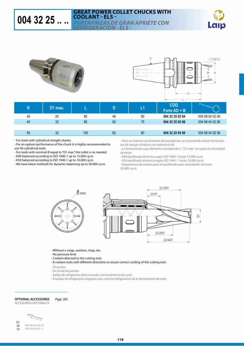
GREAT POWER COLLET CHUCKS WITH COOLANT - ELS -PORTAPINZAS DE GRAN APRIETE CON REFRIGERACION - ELS -
119
ROTATORY COOLANT ADAPTERSALIMENTADORES ROTATIVOS DE REFRIGERACIÓN
120
WELDON HOLDERSPORTAFRESAS WELDON
123
WELDON AND WHISTLE-NOTCH HOLDERSPORTAFRESAS WELDON-WHISTLE-NOTCH
125
SHORT DRILL CHUCKSPORTABROCAS INTEGRAL
126
SHRINK FIT CHUCKSPORTAHERRAMIENTAS DE AMARRE POR CONTRACCIÓN TÉRMICA - ESTÁNDAR -
127
SHRINK FIT CHUCKS WITH COOLANT - ELS -PORTAHERRAMIENTAS DE AMARRE POR CONTRACCIÓN TÉRMICA CON REFRIGERACIÓN - ELS -
129
SHRINK FIT CHUCKS - SLIM LINE -PORTAHERRAMIENTAS DE AMARRE POR CONTRACCIÓN TÉRMICA - SERIE FINA -
130
TAPPING CHUCKS WITH RELEASING DRIVE SYSTEMSelf feed and compression systemPORTAMACHOS CON SISTEMA DE ESCAPEDoble compensación axial
131
TAPPING CHUCKSReleasing drive systemPORTAMACHOS Con sistema de escape
132
TAPPING CHUCKS WITH RELEASING DRIVE SYSTEMSelf feed and compression systemPORTAMACHOS CON SISTEMA DE ESCAPEDoble compensación axial
133
QUICK-CHANGE TAPPING CHUCKSFor Bilz system tap adapterPORTAMACHOSPara sistemas BILZ
134
QUICK-CHANGE SOLID DRIVE TAPPING CHUCKSFor synchronized feed control machinesPORTAMACHOS RÍGIDO DE CAMBIO RÁPIDOExclusivo para máquinas de control de roscado rígido
135
TOOLHOLDER BLANKSPORTAHERRAMIENTAS SEMIACABADOS
136
102
K D1 h6 L L1 L2 D COD. Form A
30 16 50 17 27 32 001 12 02 01 3030 22 50 19 31 40 001 12 02 01 4030 27 55 21 33 48 001 12 02 01 50
40 16 55 17 27 32 001 12 02 02 3040 16 100 17 27 32 001 12 02 02 3140 22 55 19 31 40 001 12 02 02 4040 22 100 19 31 40 001 12 02 02 4140 27 55 21 33 48 001 12 02 02 5040 27 100 21 33 48 001 12 02 02 5140 32 60 24 38 58 001 12 02 02 6040 32 100 24 38 58 001 12 02 02 6140 40 60 27 41 70 001 12 02 02 7040 40 100 27 41 70 001 12 02 02 71
50 16 70 17 27 32 001 12 02 04 3050 16 100 17 27 32 001 12 02 04 3150 22 70 19 31 40 001 12 02 04 4050 22 100 19 31 40 001 12 02 04 4150 27 70 21 33 48 001 12 02 04 5050 27 100 21 33 48 001 12 02 04 5150 32 70 24 38 58 001 12 02 04 6050 32 100 24 38 58 001 12 02 04 6150 40 70 27 41 70 001 12 02 04 7050 40 100 27 41 70 001 12 02 04 7150 50 70 30 46 90 001 12 02 04 8050 50 125 30 46 90 001 12 02 04 81
Para fresas con chavetero longitudinal o transversal DIN 138.
001 12 02 .. ..
Page: 293 Page: 293
For milling cutters with longitudinal or driving slot DIN 138.
POrTafreSaS COMBINadOUnIvERSAl ARBORS
ACCESORIOS INCLUIDOSACCESSORIES INCLUDED
ACCESORIOS OPCIONALESOPTIONAL ACCESSORIES
103
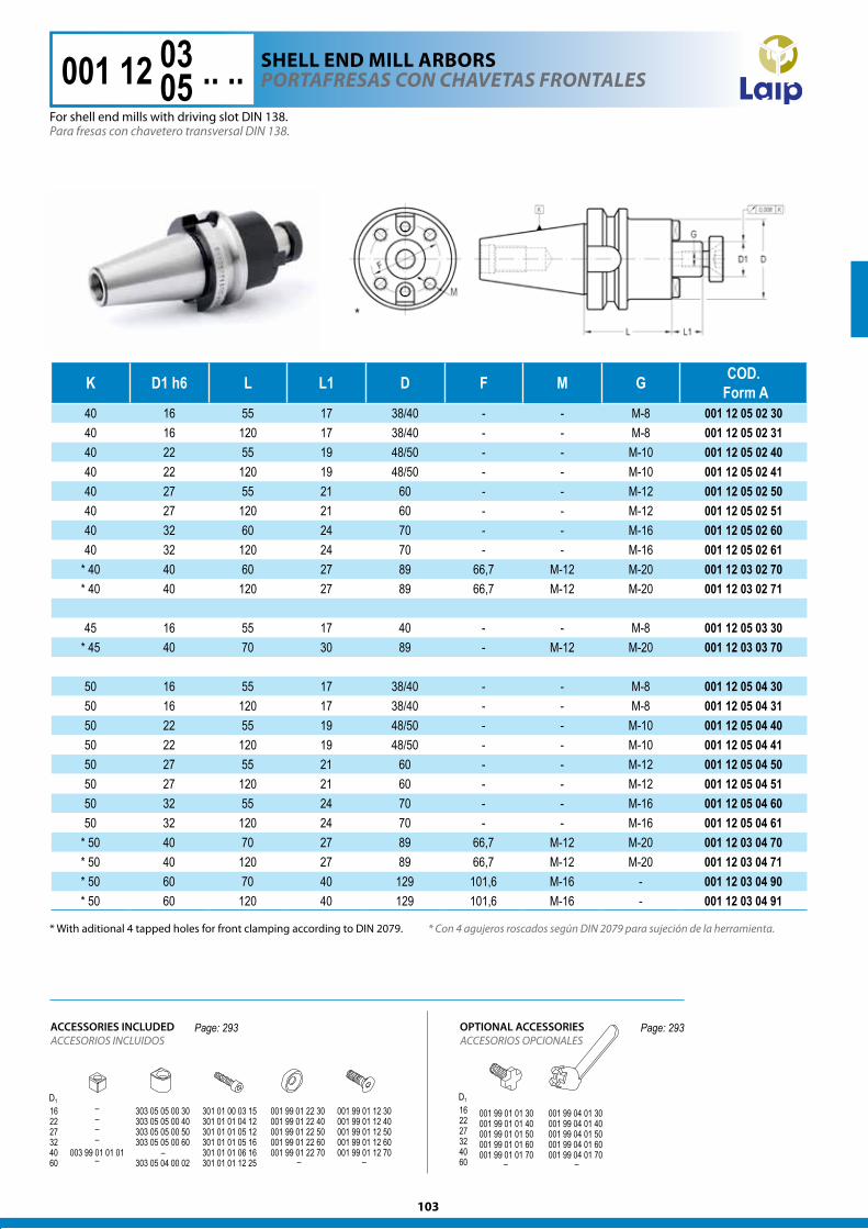
K D1 h6 L L1 D F M G COD. Form A
40 16 55 17 38/40 - - M-8 001 12 05 02 3040 16 120 17 38/40 - - M-8 001 12 05 02 3140 22 55 19 48/50 - - M-10 001 12 05 02 4040 22 120 19 48/50 - - M-10 001 12 05 02 4140 27 55 21 60 - - M-12 001 12 05 02 5040 27 120 21 60 - - M-12 001 12 05 02 5140 32 60 24 70 - - M-16 001 12 05 02 6040 32 120 24 70 - - M-16 001 12 05 02 61
* 40 40 60 27 89 66,7 M-12 M-20 001 12 03 02 70* 40 40 120 27 89 66,7 M-12 M-20 001 12 03 02 71
45 16 55 17 40 - - M-8 001 12 05 03 30* 45 40 70 30 89 - M-12 M-20 001 12 03 03 70
50 16 55 17 38/40 - - M-8 001 12 05 04 3050 16 120 17 38/40 - - M-8 001 12 05 04 3150 22 55 19 48/50 - - M-10 001 12 05 04 4050 22 120 19 48/50 - - M-10 001 12 05 04 4150 27 55 21 60 - - M-12 001 12 05 04 5050 27 120 21 60 - - M-12 001 12 05 04 5150 32 55 24 70 - - M-16 001 12 05 04 6050 32 120 24 70 - - M-16 001 12 05 04 61
* 50 40 70 27 89 66,7 M-12 M-20 001 12 03 04 70* 50 40 120 27 89 66,7 M-12 M-20 001 12 03 04 71* 50 60 70 40 129 101,6 M-16 - 001 12 03 04 90* 50 60 120 40 129 101,6 M-16 - 001 12 03 04 91
ACCESORIOS INCLUIDOSACCESSORIES INCLUDED
ACCESORIOS OPCIONALESOPTIONAL ACCESSORIES
Para fresas con chavetero transversal DIN 138.
POrTafreSaS CON ChaveTaS frONTaleS 001 12 05 .. ..0305
* Con 4 agujeros roscados según DIN 2079 para sujeción de la herramienta.* With aditional 4 tapped holes for front clamping according to DIN 2079.
Page: 293 Page: 293
For shell end mills with driving slot DIN 138.
ShEll EnD MIll ARBORS
104
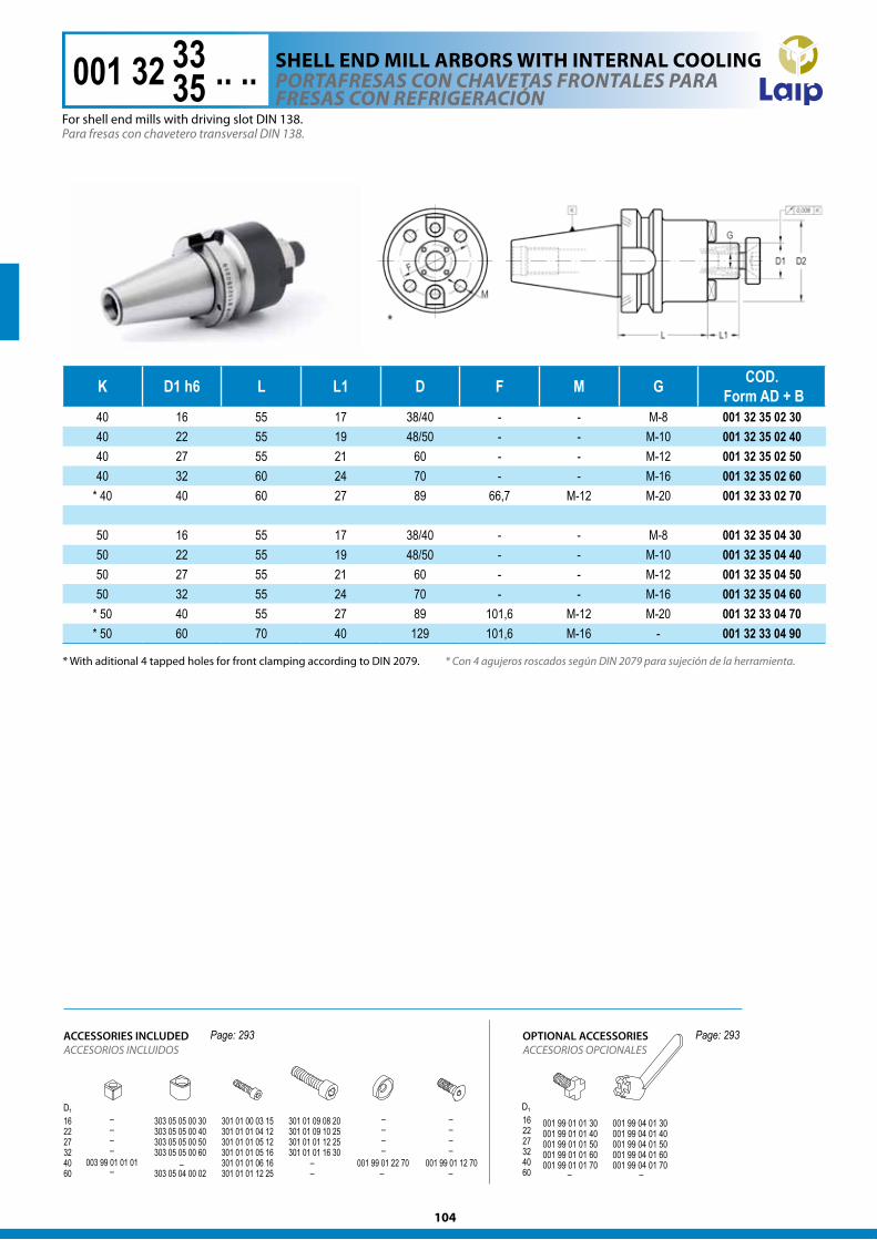
* Con 4 agujeros roscados según DIN 2079 para sujeción de la herramienta.* With aditional 4 tapped holes for front clamping according to DIN 2079.
K D1 h6 L L1 D F M G COD. Form AD + B
40 16 55 17 38/40 - - M-8 001 32 35 02 3040 22 55 19 48/50 - - M-10 001 32 35 02 4040 27 55 21 60 - - M-12 001 32 35 02 5040 32 60 24 70 - - M-16 001 32 35 02 60
* 40 40 60 27 89 66,7 M-12 M-20 001 32 33 02 70
50 16 55 17 38/40 - - M-8 001 32 35 04 3050 22 55 19 48/50 - - M-10 001 32 35 04 4050 27 55 21 60 - - M-12 001 32 35 04 5050 32 55 24 70 - - M-16 001 32 35 04 60
* 50 40 55 27 89 101,6 M-12 M-20 001 32 33 04 70* 50 60 70 40 129 101,6 M-16 - 001 32 33 04 90
POrTafreSaS CON ChaveTaS frONTaleS Para freSaS CON refrIgeraCIóN
Para fresas con chavetero transversal DIN 138.
001 32 05 .. ..3335
ShEll EnD MIll ARBORS wITh InTERnAl cOOlIng
For shell end mills with driving slot DIN 138.
ACCESORIOS INCLUIDOSACCESSORIES INCLUDED
ACCESORIOS OPCIONALESOPTIONAL ACCESSORIESPage: 293 Page: 293
105
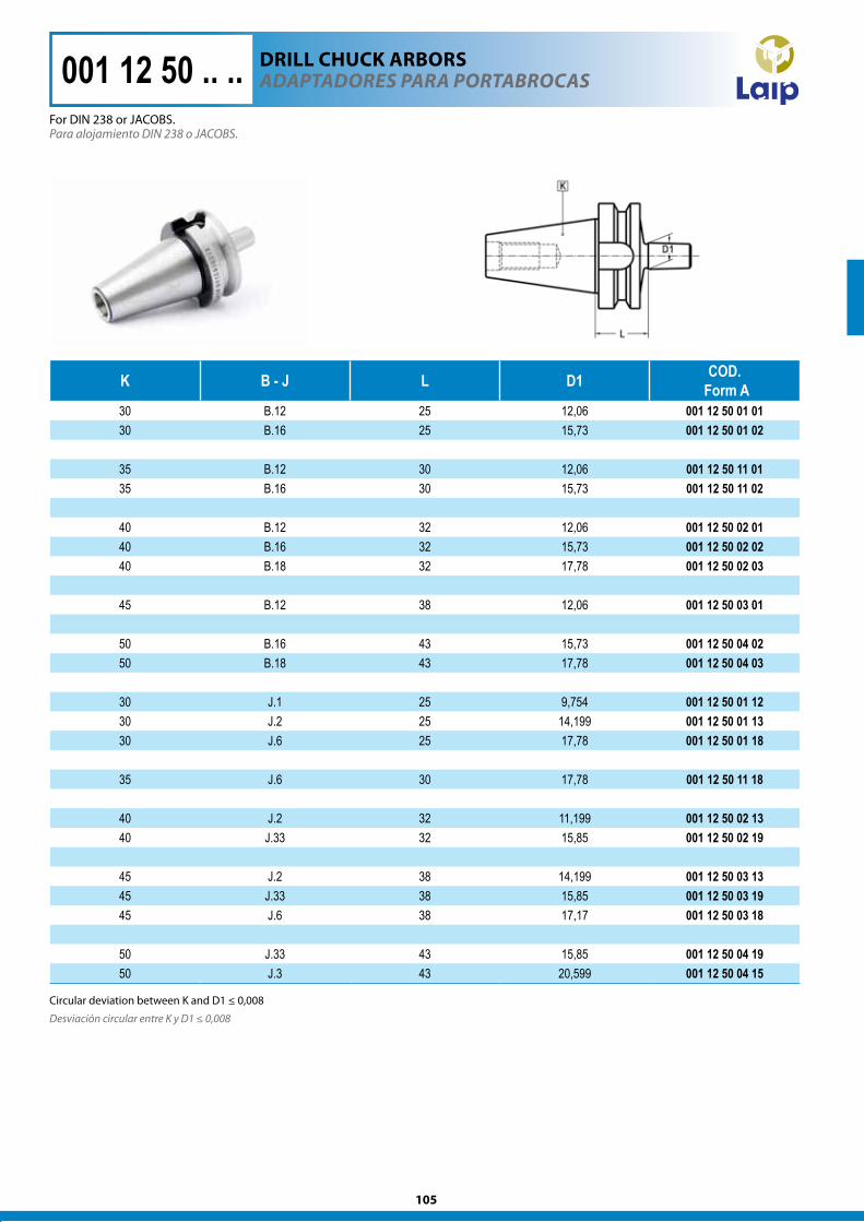
Desviación circular entre K y D1 ≤ 0,008
Circular deviation between K and D1 ≤ 0,008
K B - J L D1 COD. Form A
30 B.12 25 12,06 001 12 50 01 0130 B.16 25 15,73 001 12 50 01 02
35 B.12 30 12,06 001 12 50 11 0135 B.16 30 15,73 001 12 50 11 02
40 B.12 32 12,06 001 12 50 02 0140 B.16 32 15,73 001 12 50 02 0240 B.18 32 17,78 001 12 50 02 03
45 B.12 38 12,06 001 12 50 03 01
50 B.16 43 15,73 001 12 50 04 0250 B.18 43 17,78 001 12 50 04 03
30 J.1 25 9,754 001 12 50 01 1230 J.2 25 14,199 001 12 50 01 1330 J.6 25 17,78 001 12 50 01 18
35 J.6 30 17,78 001 12 50 11 18
40 J.2 32 11,199 001 12 50 02 1340 J.33 32 15,85 001 12 50 02 19
45 J.2 38 14,199 001 12 50 03 1345 J.33 38 15,85 001 12 50 03 1945 J.6 38 17,17 001 12 50 03 18
50 J.33 43 15,85 001 12 50 04 1950 J.3 43 20,599 001 12 50 04 15
001 12 50 .. .. adaPTadOreS Para POrTaBrOCaSDRIll chUck ARBORS
Para alojamiento DIN 238 o JACOBS.For DIN 238 or JACOBS.
106
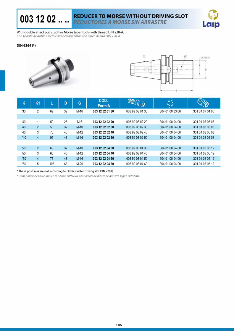
K K1 L D G COD. Form A
30 2 62 32 M-10 003 12 02 01 30 003 99 08 01 30 304 01 00 03 00 301 01 07 04 05
40 1 50 25 M-6 003 12 02 02 20 003 99 08 02 20 304 01 00 04 00 301 01 03 05 0840 2 50 32 M-10 003 12 02 02 30 003 99 08 02 30 304 01 00 04 00 301 01 03 05 0840 3 70 40 M-12 003 12 02 02 40 003 99 08 02 40 304 01 00 04 00 301 01 03 05 08*40 4 95 48 M-16 003 12 02 02 50 003 99 08 02 50 304 01 00 04 00 301 01 03 05 08
50 2 60 32 M-10 003 12 02 04 30 003 99 08 04 30 304 01 00 04 00 301 01 03 05 1250 3 65 40 M-12 003 12 02 04 40 003 99 08 04 40 304 01 00 04 00 301 01 03 05 12*50 4 75 48 M-16 003 12 02 04 50 003 99 08 04 50 304 01 00 04 00 301 01 03 05 12*50 5 103 63 M-20 003 12 02 04 60 003 99 08 04 60 304 01 00 04 00 301 01 03 05 12
Con tirante de doble efecto.Para herramientas con rosca de tiro DIN 228-A.
DIn 6364 (*)
reduCTOreS a MOrSe SIN arraSTre003 12 02 .. ..
* Estas posiciones no cumplen la norma DIN 6364 por carecer de diente de arrastre según DIN 2201.
* These positions are not according to DIN 6364 (No driving slot DIN 2201).
With double effect pull stud For Morse taper tools with thread DIN 228-A.
REDUcER TO MORSE wIThOUT DRIvIng SlOT
107
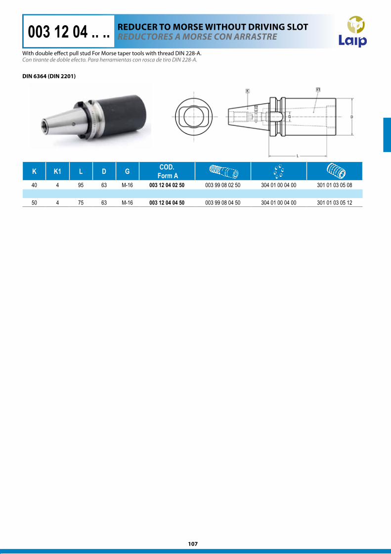
K K1 L D G COD. Form A
40 4 95 63 M-16 003 12 04 02 50 003 99 08 02 50 304 01 00 04 00 301 01 03 05 08
50 4 75 63 M-16 003 12 04 04 50 003 99 08 04 50 304 01 00 04 00 301 01 03 05 12
003 12 04 .. .. reduCTOreS a MOrSe CON arraSTre
Con tirante de doble efecto. Para herramientas con rosca de tiro DIN 228-A.
DIn 6364 (DIn 2201)
REDUcER TO MORSE wIThOUT DRIvIng SlOT
With double effect pull stud For Morse taper tools with thread DIN 228-A.
108
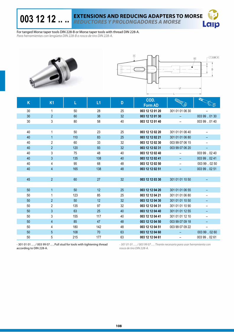
K K1 L L1 D COD. Form AD
30 1 50 28 25 003 12 12 01 20 301 01 01 06 30 –30 2 60 38 32 003 12 12 01 30 – 003 99 .. 01 3030 3 80 58 40 003 12 12 01 40 – 003 99 .. 01 40
40 1 50 23 25 003 12 12 02 20 301 01 01 06 40 –40 1 110 83 25 003 12 12 02 21 301 01 01 06 80 –40 2 60 33 32 003 12 12 02 30 003 99 07 06 15 –40 2 120 93 32 003 12 12 02 31 003 99 07 06 20 –40 3 75 48 40 003 12 12 02 40 – 003 99 .. 02 4040 3 135 108 40 003 12 12 02 41 – 003 99 .. 02 4140 4 95 68 48 003 12 12 02 50 – 003 99 .. 02 5040 4 165 138 48 003 12 12 02 51 – 003 99 .. 02 51
45 2 60 27 32 003 12 12 03 30 301 01 01 10 50 –
50 1 50 12 25 003 12 12 04 20 301 01 01 06 55 –50 1 123 85 25 003 12 12 04 21 301 01 01 06 80 –50 2 50 12 32 003 12 12 04 30 301 01 01 10 50 –50 2 135 97 32 003 12 12 04 31 301 01 01 10 90 –50 3 63 25 40 003 12 12 04 40 301 01 01 12 55 –50 3 155 117 40 003 12 12 04 41 301 01 01 12 10 –50 4 85 47 48 003 12 12 04 50 003 99 07 09 18 –50 4 180 142 48 003 12 12 04 51 003 99 07 09 22 –50 5 108 70 63 003 12 12 04 60 – 003 99 .. 02 6050 5 215 177 63 003 12 12 04 61 – 003 99 .. 02 61
Para herramientas con lengüeta DIN 228-B o rosca de tiro DIN 228-A.
- 301 01 01 .. .. / 003 99 07 .. .. Tirante necesario para usar herramienta con rosca de tiro DIN 228-A.
reduCTOreS y PrOlONgadOreS a MOrSe003 12 12 .. ..
- 301 01 01 .. .. / 003 99 07 .. .. Pull stud for tools with tightening thread according to DIN 228-A.
For tanged Morse taper tools DIN 228-B or Morse taper tools with thread DIN 228-A.
ExTEnSIOnS AnD REDUcIng ADAPTERS TO MORSE
109
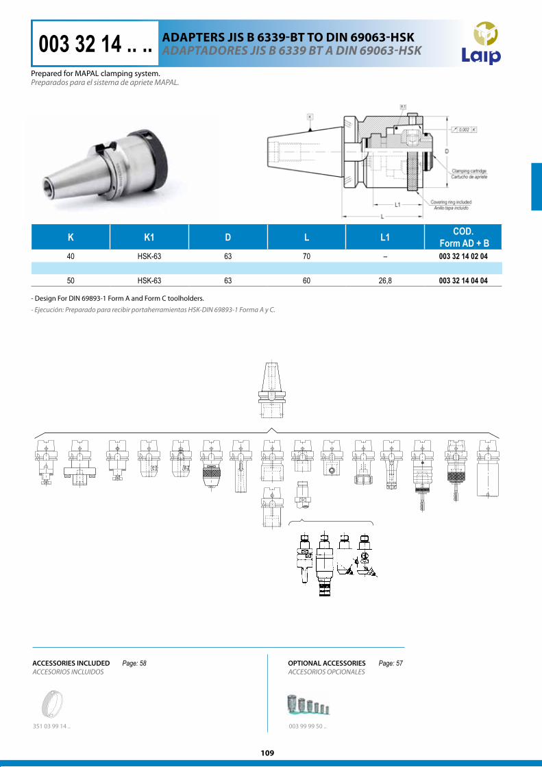
K K1 D L L1 COD. Form AD + B
40 HSK-63 63 70 – 003 32 14 02 04
50 HSK-63 63 60 26,8 003 32 14 04 04
Preparados para el sistema de apriete MAPAL.
- Ejecución: Preparado para recibir portaherramientas HSK-DIN 69893-1 Forma A y C.
adaPTadOreS JIS B 6339 BT a dIN 69063-hSK003 32 14 .. ..
- Design For DIN 69893-1 Form A and Form C toolholders.
Prepared for MAPAL clamping system.
ADAPTERS JIS B 6339-BT TO DIn 69063-hSk
ACCESORIOS INCLUIDOS
351 03 99 14 .. 003 99 99 50 ..
ACCESSORIES INCLUDEDACCESORIOS OPCIONALESOPTIONAL ACCESSORIESPage: 58 Page: 57
110
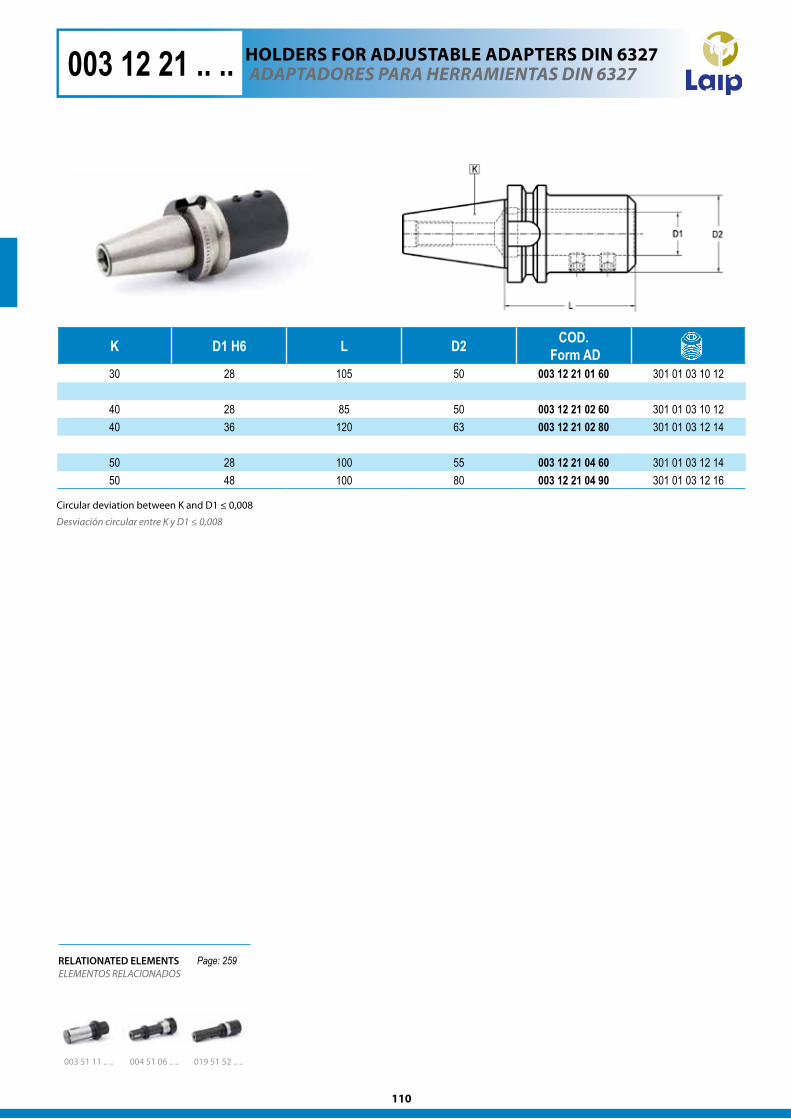
K D1 H6 L D2 COD. Form AD
30 28 105 50 003 12 21 01 60 301 01 03 10 12
40 28 85 50 003 12 21 02 60 301 01 03 10 1240 36 120 63 003 12 21 02 80 301 01 03 12 14
50 28 100 55 003 12 21 04 60 301 01 03 12 1450 48 100 80 003 12 21 04 90 301 01 03 12 16
003 12 21 .. .. adaPTadOreS Para herraMIeNTaS dIN 6327
Desviación circular entre K y D1 ≤ 0,008
RELATIONATED ELEMENTSELEMENTOS RELACIONADOS
019 51 52 .. ..003 51 11 .. .. 004 51 06 .. ..
hOlDERS FOR ADJUSTABlE ADAPTERS DIn 6327
Circular deviation between K and D1 ≤ 0,008
Page: 259
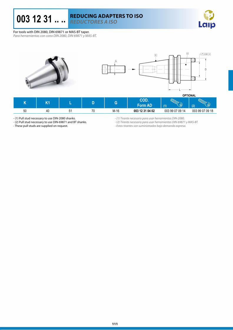
111
K K1 L D G COD. Form AD
50 40 51 70 M-16 003 12 31 04 02 003 99 07 09 14 003 99 07 09 18
Para herramientas con cono DIN 2080, DIN 69871 y MAS-BT.
- (1) Tirante necesario para usar herramientas DIN-2080. - (2) Tirante necesario para usar herramientas DIN-69871 y MAS-BT. - Estos tirantes son suministrados bajo demanda expresa.
reduCTOreS a ISO003 12 31 .. ..
OPTIONAL
(1) (2)
- (1) Pull stud necessary to use DIN-2080 shanks. - (2) Pull stud necessary to use DIN-69871 and BT shanks. - These pull studs are supplied on request.
For tools with DIN 2080, DIN 69871 or MAS-BT taper.
REDUcIng ADAPTERS TO ISO
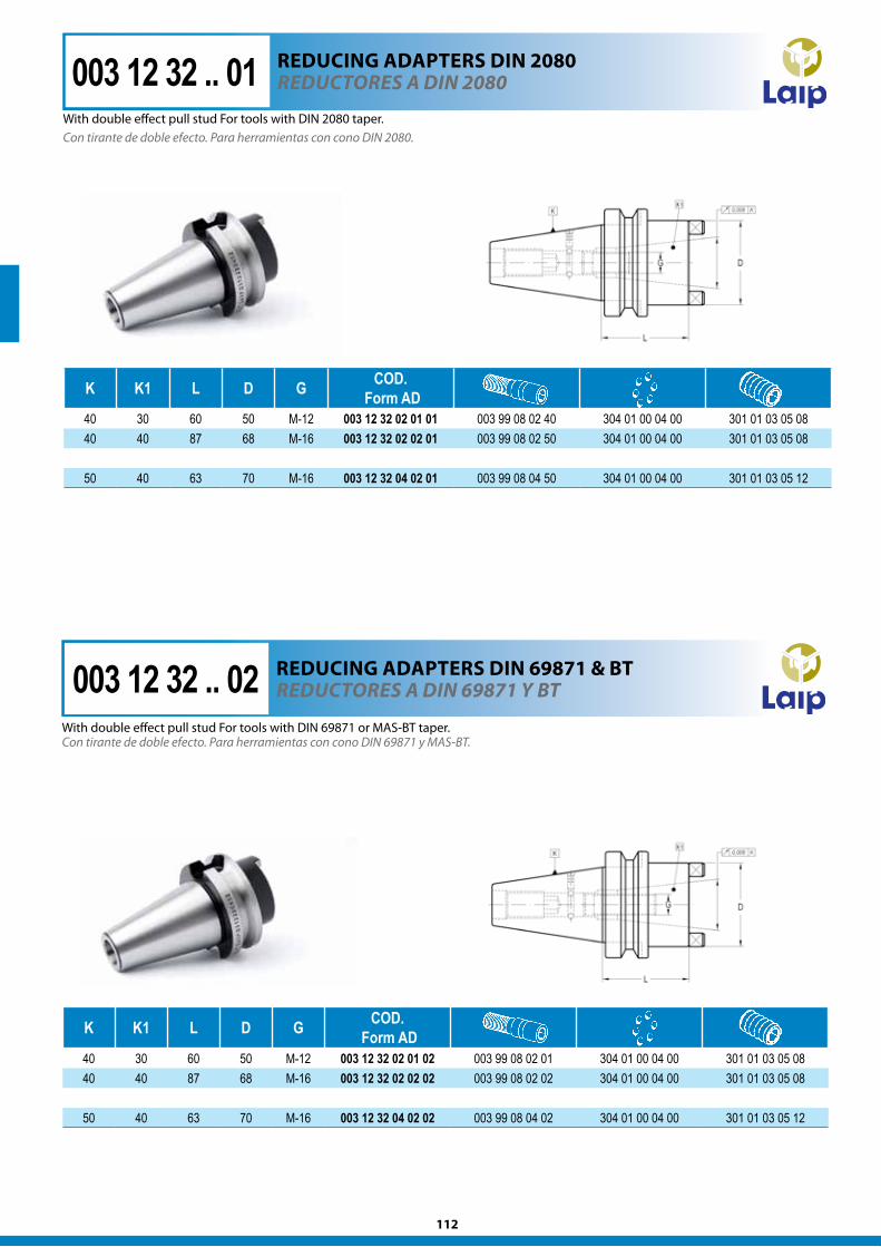
112
K K1 L D G COD. Form AD
40 30 60 50 M-12 003 12 32 02 01 01 003 99 08 02 40 304 01 00 04 00 301 01 03 05 0840 40 87 68 M-16 003 12 32 02 02 01 003 99 08 02 50 304 01 00 04 00 301 01 03 05 08
50 40 63 70 M-16 003 12 32 04 02 01 003 99 08 04 50 304 01 00 04 00 301 01 03 05 12
K K1 L D G COD. Form AD
40 30 60 50 M-12 003 12 32 02 01 02 003 99 08 02 01 304 01 00 04 00 301 01 03 05 0840 40 87 68 M-16 003 12 32 02 02 02 003 99 08 02 02 304 01 00 04 00 301 01 03 05 08
50 40 63 70 M-16 003 12 32 04 02 02 003 99 08 04 02 304 01 00 04 00 301 01 03 05 12
Con tirante de doble efecto. Para herramientas con cono DIN 69871 y MAS-BT.
reduCTOreS a dIN 69871 y BT003 12 32 .. 02With double effect pull stud For tools with DIN 69871 or MAS-BT taper.
REDUcIng ADAPTERS DIn 69871 & BT
003 12 32 .. 01 reduCTOreS a dIN 2080
Con tirante de doble efecto. Para herramientas con cono DIN 2080.
REDUcIng ADAPTERS DIn 2080
With double effect pull stud For tools with DIN 2080 taper.
113
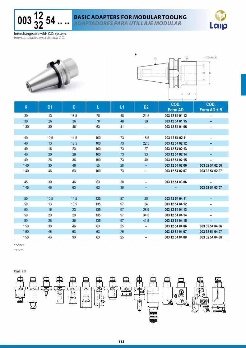
K D1 D L L1 D2 COD.Form AD
COD.Form AD + B
30 13 18,5 70 48 21,5 003 12 54 01 12 –30 26 36 70 48 39 003 12 54 01 15 –
* 30 30 46 63 41 – 003 12 54 01 06 –
40 10,5 14,5 100 73 18,5 003 12 54 02 11 –40 13 18,5 100 73 22,5 003 12 54 02 12 –40 16 23 100 73 27 003 12 54 02 13 –40 20 29 100 73 33 003 12 54 02 14 –40 26 36 100 73 40 003 12 54 02 15 –
* 40 30 46 55 28 – 003 12 54 02 06 003 32 54 02 06* 40 46 63 100 73 – 003 12 54 02 07 003 32 54 02 07
45 30 46 63 30 – 003 12 54 03 06 –* 45 46 63 63 30 – – 003 32 54 03 07
50 10,5 14,5 135 97 20 003 12 54 04 11 –50 13 18,5 135 97 24 003 12 54 04 12 –50 16 23 135 97 28,5 003 12 54 04 13 –50 20 29 135 97 34,5 003 12 54 04 14 –50 26 36 135 97 41,5 003 12 54 04 15 –
* 50 30 46 63 25 – 003 12 54 04 06 003 32 54 04 06* 50 46 63 63 25 – 003 12 54 04 07 003 32 54 04 07* 50 46 90 63 25 – 003 12 54 04 08 003 32 54 04 08
adaPTadOreS Para uTIllaJe MOdular
Intercambiable con el sistema C.O.
* Corto.
003 12 54 .. ..1232
*
BASIc ADAPTERS FOR MODUlAR TOOlIng
Interchangeable with C.O. system.
* Short.
Page: 221
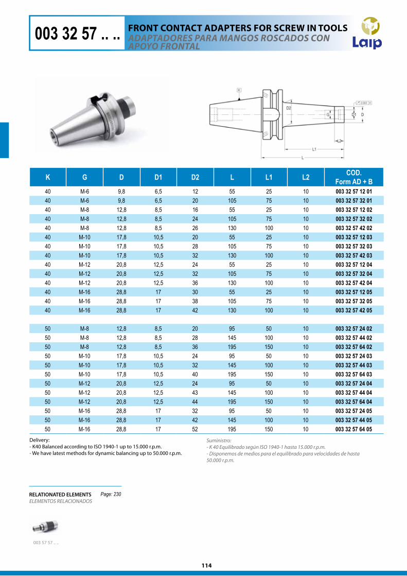
114
K G D D1 D2 L L1 L2 COD.Form AD + B
40 M-6 9,8 6,5 12 55 25 10 003 32 57 12 0140 M-6 9,8 6,5 20 105 75 10 003 32 57 32 0140 M-8 12,8 8,5 16 55 25 10 003 32 57 12 0240 M-8 12,8 8,5 24 105 75 10 003 32 57 32 0240 M-8 12,8 8,5 26 130 100 10 003 32 57 42 0240 M-10 17,8 10,5 20 55 25 10 003 32 57 12 0340 M-10 17,8 10,5 28 105 75 10 003 32 57 32 0340 M-10 17,8 10,5 32 130 100 10 003 32 57 42 0340 M-12 20,8 12,5 24 55 25 10 003 32 57 12 0440 M-12 20,8 12,5 32 105 75 10 003 32 57 32 0440 M-12 20,8 12,5 36 130 100 10 003 32 57 42 0440 M-16 28,8 17 30 55 25 10 003 32 57 12 0540 M-16 28,8 17 38 105 75 10 003 32 57 32 0540 M-16 28,8 17 42 130 100 10 003 32 57 42 05
50 M-8 12,8 8,5 20 95 50 10 003 32 57 24 0250 M-8 12,8 8,5 28 145 100 10 003 32 57 44 0250 M-8 12,8 8,5 36 195 150 10 003 32 57 64 0250 M-10 17,8 10,5 24 95 50 10 003 32 57 24 0350 M-10 17,8 10,5 32 145 100 10 003 32 57 44 0350 M-10 17,8 10,5 40 195 150 10 003 32 57 64 0350 M-12 20,8 12,5 24 95 50 10 003 32 57 24 0450 M-12 20,8 12,5 43 145 100 10 003 32 57 44 0450 M-12 20,8 12,5 44 195 150 10 003 32 57 64 0450 M-16 28,8 17 32 95 50 10 003 32 57 24 0550 M-16 28,8 17 42 145 100 10 003 32 57 44 0550 M-16 28,8 17 52 195 150 10 003 32 57 64 05
Suministro:- K 40 Equilibrado según ISO 1940-1 hasta 15.000 r.p.m. - Disponemos de medios para el equilibrado para velocidades de hasta 50.000 r.p.m.
adaPTadOreS Para MaNgOS rOSCadOS CON aPOyO frONTal
003 57 57 .. ..
ELEMENTOS RELACIONADOSRELATIONATED ELEMENTS
003 32 57 .. ..
Page: 230
Delivery:- K40 Balanced according to ISO 1940-1 up to 15.000 r.p.m. - We have latest methods for dynamic balancing up to 50.000 r.p.m.
FROnT cOnTAcT ADAPTERS FOR ScREw In TOOlS
115
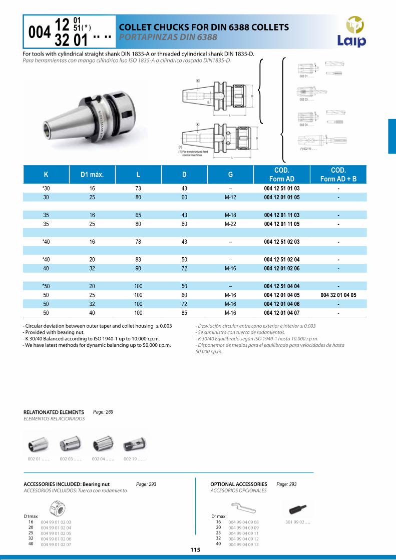
K D1 máx. L D G COD.Form AD
COD.Form AD + B
*30 16 73 43 – 004 12 51 01 03 -30 25 80 60 M-12 004 12 01 01 05 -
35 16 65 43 M-18 004 12 01 11 03 -35 25 80 60 M-22 004 12 01 11 05 -
*40 16 78 43 – 004 12 51 02 03 -
*40 20 83 50 – 004 12 51 02 04 -40 32 90 72 M-16 004 12 01 02 06 -
*50 20 100 50 – 004 12 51 04 04 -50 25 100 60 M-16 004 12 01 04 05 004 32 01 04 0550 32 100 72 M-16 004 12 01 04 06 -50 40 100 85 M-16 004 12 01 04 07 -
POrTaPINzaS dIN 6388
Para herramientas con mango cilíndrico liso ISO 1835-A o cilíndrico roscado DIN1835-D.
- Desviación circular entre cono exterior e interior ≤ 0,003- Se suministra con tuerca de rodamientos. - K 30/40 Equilibrado según ISO 1940-1 hasta 10.000 r.p.m. - Disponemos de medios para el equilibrado para velocidades de hasta 50.000 r.p.m.
RELATIONATED ELEMENTSELEMENTOS RELACIONADOS
004 12 54 .. ..1232 01
51 *01
( )
301 99 02 .. ..
002 04 .. .. ..002 03 .. .. ..002 01 .. .. .. 002 19 .. .. ..
ACCESORIOS INCLUIDOS: Tuerca con rodamientoACCESSORIES INCLUDED: Bearing nut
Page: 269
Page: 293 Page: 293
cOllET chUckS FOR DIn 6388 cOllETS
For tools with cylindrical straight shank DIN 1835-A or threaded cylindrical shank DIN 1835-D.
- Circular deviation between outer taper and collet housing ≤ 0,003- Provided with bearing nut.- K 30/40 Balanced according to ISO 1940-1 up to 10.000 r.p.m. - We have latest methods for dynamic balancing up to 50.000 r.p.m.
OPTIONAL ACCESSORIESACCESORIOS OPCIONALES
004 99 01 02 03 004 99 01 02 04 004 99 01 02 05 004 99 01 02 06 004 99 01 02 07
004 99 04 09 08 004 99 04 09 09 004 99 04 09 11 004 99 04 09 12 004 99 04 09 13
D1max1620253240
D1max1620253240
116
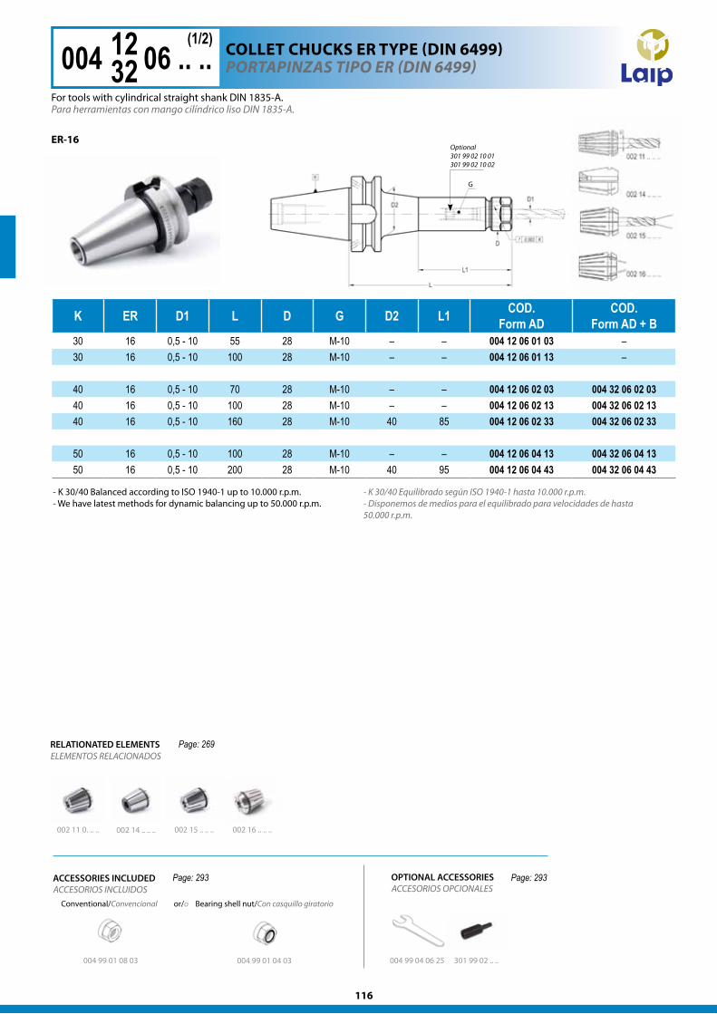
K ER D1 L D G D2 L1 COD.Form AD
COD.Form AD + B
30 16 0,5 - 10 55 28 M-10 – – 004 12 06 01 03 –30 16 0,5 - 10 100 28 M-10 – – 004 12 06 01 13 –
40 16 0,5 - 10 70 28 M-10 – – 004 12 06 02 03 004 32 06 02 0340 16 0,5 - 10 100 28 M-10 – – 004 12 06 02 13 004 32 06 02 1340 16 0,5 - 10 160 28 M-10 40 85 004 12 06 02 33 004 32 06 02 33
50 16 0,5 - 10 100 28 M-10 – – 004 12 06 04 13 004 32 06 04 1350 16 0,5 - 10 200 28 M-10 40 95 004 12 06 04 43 004 32 06 04 43
Para herramientas con mango cilíndrico liso DIN 1835-A.
POrTaPINzaS TIPO er (dIN 6499)004 12 06 .. ..1232
(1/2)
ACCESORIOS INCLUIDOSACCESSORIES INCLUDED
or/oConventional/Convencional Bearing shell nut/Con casquillo giratorio
ER-16
Page: 293 Page: 293
Optional 301 99 02 10 01 301 99 02 10 02
ELEMENTOS RELACIONADOSRELATIONATED ELEMENTS
002 11 0. .. .. 002 15 .. .. ..002 14 .. .. .. 002 16 .. .. ..
Page: 269
G G
For tools with cylindrical straight shank DIN 1835-A.
cOllET chUckS ER TyPE (DIn 6499)
- K 30/40 Equilibrado según ISO 1940-1 hasta 10.000 r.p.m. - Disponemos de medios para el equilibrado para velocidades de hasta 50.000 r.p.m.
004 99 01 08 03 004 99 01 04 03 004 99 04 06 25 301 99 02 .. ..
- K 30/40 Balanced according to ISO 1940-1 up to 10.000 r.p.m. - We have latest methods for dynamic balancing up to 50.000 r.p.m.
ACCESORIOS OPCIONALESOPTIONAL ACCESSORIES
117
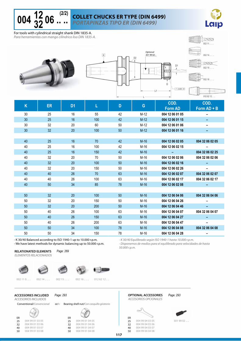
K ER D1 L D G COD.Form AD
COD.Form AD + B
30 25 16 55 42 M-12 004 12 06 01 05 –30 25 16 100 42 M-12 004 12 06 01 15 –30 32 20 60 50 M-12 004 12 06 01 06 –30 32 20 100 50 M-12 004 12 06 01 16 –
40 25 16 70 42 M-16 004 12 06 02 05 004 32 06 02 0540 25 16 100 42 M-16 004 12 06 02 15 –40 25 16 150 42 M-16 – 004 32 06 02 2540 32 20 70 50 M-16 004 12 06 02 06 004 32 06 02 0640 32 20 100 50 M-16 004 12 06 02 16 –40 32 20 150 50 M-16 004 12 06 02 26 –40 40 26 70 63 M-16 004 12 06 02 07 004 32 06 02 0740 40 26 100 63 M-16 004 12 06 02 17 004 32 06 02 1740 50 34 85 78 M-16 004 12 06 02 08 –
50 32 20 100 50 M-16 004 12 06 04 06 004 32 06 04 0650 32 20 150 50 M-16 004 12 06 04 26 –50 32 20 200 50 M-16 004 12 06 04 46 –50 40 26 100 63 M-16 004 12 06 04 07 004 32 06 04 0750 40 26 150 63 M-16 004 12 06 04 27 –50 40 26 200 63 M-16 004 12 06 04 47 –50 50 34 100 78 M-16 004 12 06 04 08 004 32 06 04 0850 50 34 150 78 M-16 004 12 06 04 28 –
- K 30/40 Equilibrado según ISO 1940-1 hasta 10.000 r.p.m. - Disponemos de medios para el equilibrado para velocidades de hasta 50.000 r.p.m.
ELEMENTOS RELACIONADOSRELATIONATED ELEMENTS
004 99 01 03 05 004 99 01 03 06 004 99 01 03 07 004 99 01 03 08
004 99 01 04 05 004 99 01 04 06 004 99 01 04 07 004 99 01 04 08
301 99 02 .. ..
- K 30/40 Balanced according to ISO 1940-1 up to 10.000 r.p.m. - We have latest methods for dynamic balancing up to 50.000 r.p.m.
ACCESORIOS OPCIONALESOPTIONAL ACCESSORIES
Para herramientas con mango cilíndrico liso DIN 1835-A.
POrTaPINzaS TIPO er (dIN 6499)004 12 06 .. ..1232
(2/2)
For tools with cylindrical straight shank DIN 1835-A.
cOllET chUckS ER TyPE (DIn 6499)
ACCESORIOS INCLUIDOSConventional/Convencional Bearing shell nut/Con casquillo giratorio
ACCESSORIES INCLUDED
or/o
ER25324050
ER25324050
004 99 04 03 05 004 99 04 03 06 004 99 04 03 07 004 99 04 04 08
ER25324050
002 11 0. .. .. 002 14 .. .. .. 002 15 .. .. .. 002 16 .. .. .. 012 62 12 .. ..
Page: 269
Page: 293 Page: 293
Optional 301 99 02 ..
118
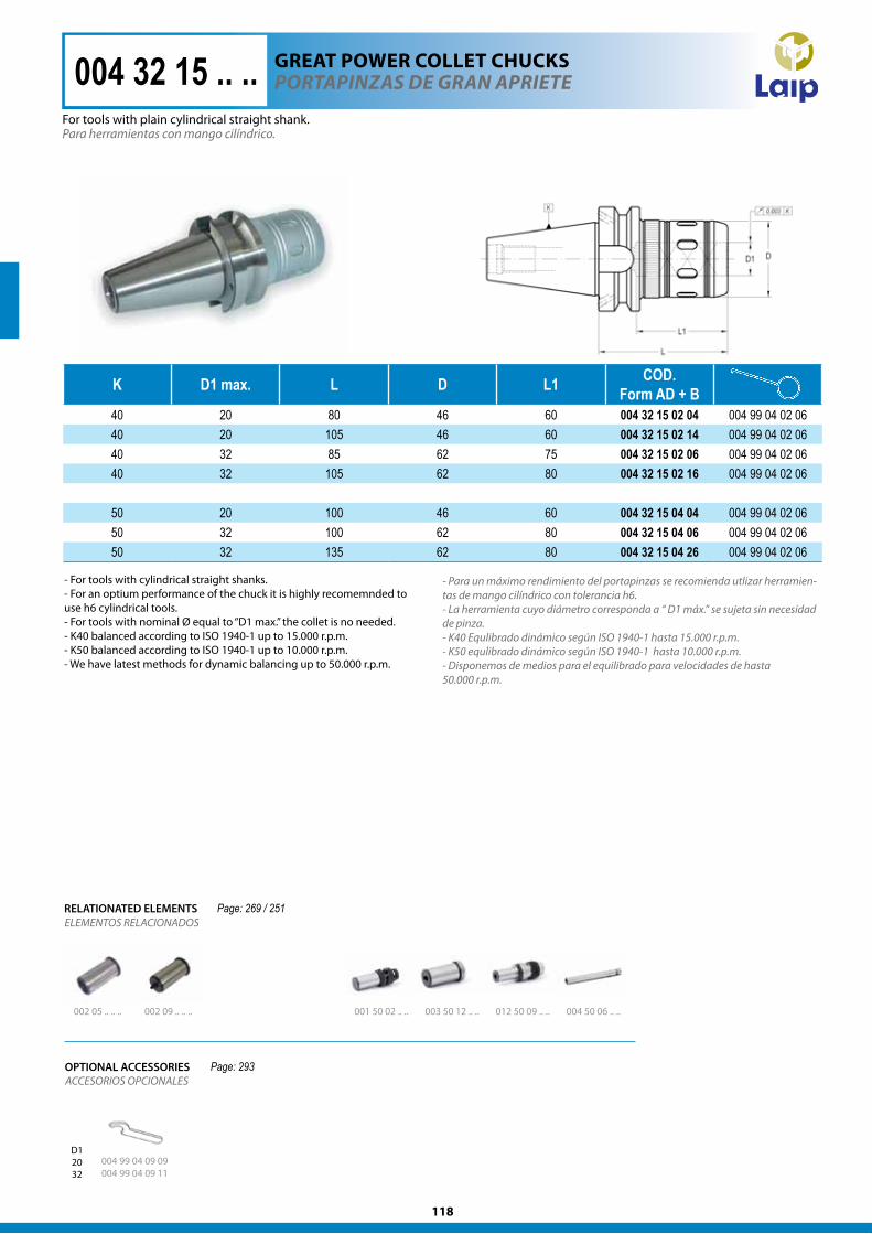
K D1 max. L D L1 COD.Form AD + B
40 20 80 46 60 004 32 15 02 04 004 99 04 02 0640 20 105 46 60 004 32 15 02 14 004 99 04 02 0640 32 85 62 75 004 32 15 02 06 004 99 04 02 0640 32 105 62 80 004 32 15 02 16 004 99 04 02 06
50 20 100 46 60 004 32 15 04 04 004 99 04 02 0650 32 100 62 80 004 32 15 04 06 004 99 04 02 0650 32 135 62 80 004 32 15 04 26 004 99 04 02 06
Para herramientas con mango cilíndrico.
- Para un máximo rendimiento del portapinzas se recomienda utlizar herramien-tas de mango cilíndrico con tolerancia h6. - La herramienta cuyo diámetro corresponda a “ D1 máx.” se sujeta sin necesidad de pinza.- K40 Equlibrado dinámico según ISO 1940-1 hasta 15.000 r.p.m. - K50 equlibrado dinámico según ISO 1940-1 hasta 10.000 r.p.m. - Disponemos de medios para el equilibrado para velocidades de hasta50.000 r.p.m.
POrTaPINzaS de graN aPrIeTe
002 05 .. .. .. 002 09 .. .. .. 001 50 02 .. ..
ELEMENTOS RELACIONADOSRELATIONATED ELEMENTS
004 32 15 .. ..
003 50 12 .. .. 012 50 09 .. .. 004 50 06 .. ..
004 99 04 09 09 004 99 04 09 11
D12032
Page: 269 / 251
Page: 293
- For tools with cylindrical straight shanks.- For an optium performance of the chuck it is highly recomemnded to use h6 cylindrical tools. - For tools with nominal Ø equal to “D1 max.” the collet is no needed. - K40 balanced according to ISO 1940-1 up to 15.000 r.p.m. - K50 balanced according to ISO 1940-1 up to 10.000 r.p.m. - We have latest methods for dynamic balancing up to 50.000 r.p.m.
For tools with plain cylindrical straight shank.
gREAT POwER cOllET chUckS
ACCESORIOS OPCIONALESOPTIONAL ACCESSORIES
119
K D1 max. L D L1 COD.Form AD + B
40 20 80 46 60 004 32 25 02 04 004 99 04 02 0640 32 85 62 75 004 32 25 02 06 004 99 04 02 06
50 32 100 62 80 004 32 25 04 06 004 99 04 02 06
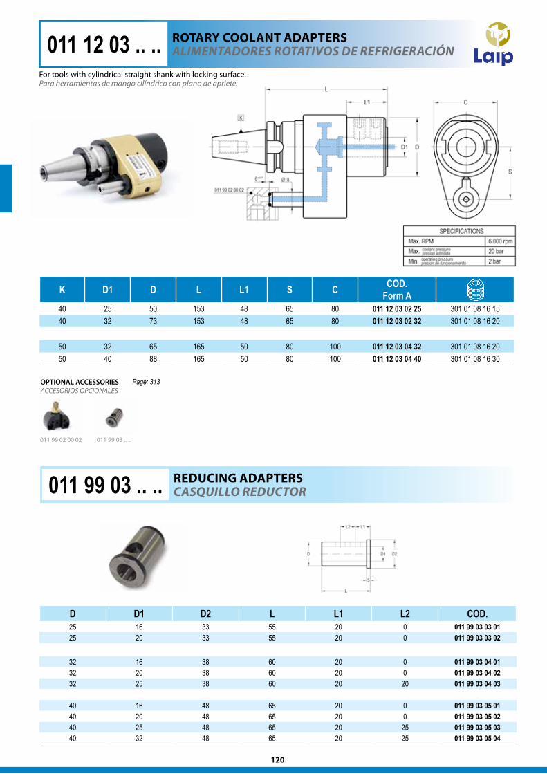
004 32 25 .. .. POrTaPINzaS de graN aPrIeTe CON refrIgeraCIóN - elS -
- Sin juntas. - Sin límite de presión.- Salida de refrigerante direccionada a la herramienta de corte.- 8 salidas de refrigerante aseguran una correcta refrigeración de la herramienta de corte.
004 99 04 09 09 004 99 04 09 11
D12032
Page: 293
gREAT POwER cOllET chUckS wITh cOOlAnT - ElS -
- Without o-rings, washers, rings, etc. - No pressure limit.- Coolant directed to the cutting tool.- 8 coolant exits with different directions to assure correct cooling of the cutting tool.
OPTIONAL ACCESSORIESACCESORIOS OPCIONALES
- Para un máximo rendimiento del portapinzas se recomienda utlizar herramien-tas de mango cilíndrico con tolerancia h6. - La herramienta cuyo diámetro corresponda a “ D1 máx.” se sujeta sin necesidad de pinza.- K40 Equlibrado dinámico según ISO 1940-1 hasta 15.000 r.p.m. - K50 equlibrado dinámico según ISO 1940-1 hasta 10.000 r.p.m. - Disponemos de medios para el equilibrado para velocidades de hasta50.000 r.p.m.
- For tools with cylindrical straight shanks.- For an optium performance of the chuck it is highly recomemnded to use h6 cylindrical tools. - For tools with nominal Ø equal to “D1 max.” the collet is no needed. - K40 balanced according to ISO 1940-1 up to 15.000 r.p.m. - K50 balanced according to ISO 1940-1 up to 10.000 r.p.m. - We have latest methods for dynamic balancing up to 50.000 r.p.m.
120
Page: 313
D D1 D2 L L1 L2 COD.25 16 33 55 20 0 011 99 03 03 0125 20 33 55 20 0 011 99 03 03 02
32 16 38 60 20 0 011 99 03 04 0132 20 38 60 20 0 011 99 03 04 0232 25 38 60 20 20 011 99 03 04 03
40 16 48 65 20 0 011 99 03 05 0140 20 48 65 20 0 011 99 03 05 0240 25 48 65 20 25 011 99 03 05 0340 32 48 65 20 25 011 99 03 05 04
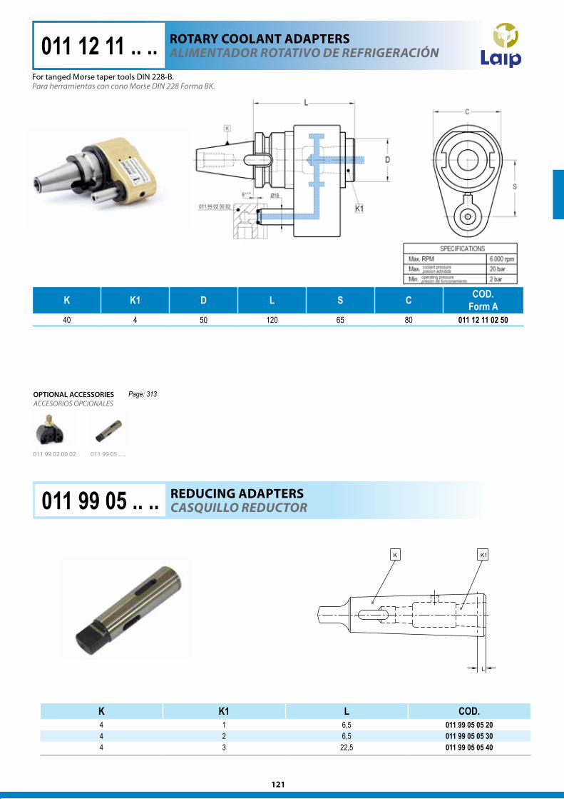
alIMeNTadOreS rOTaTIvOS de refrIgeraCIóN011 12 03 .. ..
011 99 03 .. ..011 99 02 00 02
CaSQuIllO reduCTOr011 99 03 .. .. REDUcIng ADAPTERS
Para herramientas de mango cilíndrico con plano de apriete.For tools with cylindrical straight shank with locking surface.
ROTARy cOOlAnT ADAPTERS
ACCESORIOS OPCIONALESOPTIONAL ACCESSORIES
K D1 D L L1 S C COD. Form A
40 25 50 153 48 65 80 011 12 03 02 25 301 01 08 16 1540 32 73 153 48 65 80 011 12 03 02 32 301 01 08 16 20
50 32 65 165 50 80 100 011 12 03 04 32 301 01 08 16 2050 40 88 165 50 80 100 011 12 03 04 40 301 01 08 16 30
121
Page: 313
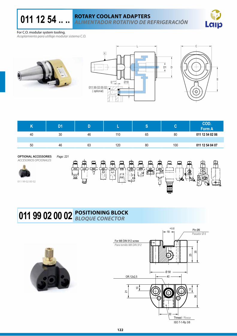
K K1 D L S C COD. Form A
40 4 50 120 65 80 011 12 11 02 50
011 12 11 .. .. alIMeNTadOr rOTaTIvO de refrIgeraCIóN
Para herramientas con cono Morse DIN 228 Forma BK.
011 99 05 .. ..011 99 02 00 02
K K1 L COD.4 1 6,5 011 99 05 05 204 2 6,5 011 99 05 05 304 3 22,5 011 99 05 05 40
CaSQuIllO reduCTOr011 99 05 .. .. REDUcIng ADAPTERS
ACCESORIOS OPCIONALESOPTIONAL ACCESSORIES
ROTARy cOOlAnT ADAPTERS
For tanged Morse taper tools DIN 228-B.
122
K D1 D L S C COD. Form A
40 30 46 110 65 80 011 12 54 02 06
50 46 63 120 80 100 011 12 54 04 07
Acoplamiento para utillaje modular sistema C.O.
alIMeNTadOr rOTaTIvO de refrIgeraCIóN011 12 54 .. ..
BlOQue CONeCTOr011 99 02 00 02 POSITIOnIng BlOck
011 99 02 00 02
ACCESORIOS OPCIONALESOPTIONAL ACCESSORIES
Pasador Ø 6
Para tornillo M8 DIN 912
Thread / Rosca
Page: 221
For C.O. modular system tooling.
ROTARy cOOlAnT ADAPTERS
123
K D1 L D COD. Form AD
COD. Form AD + B
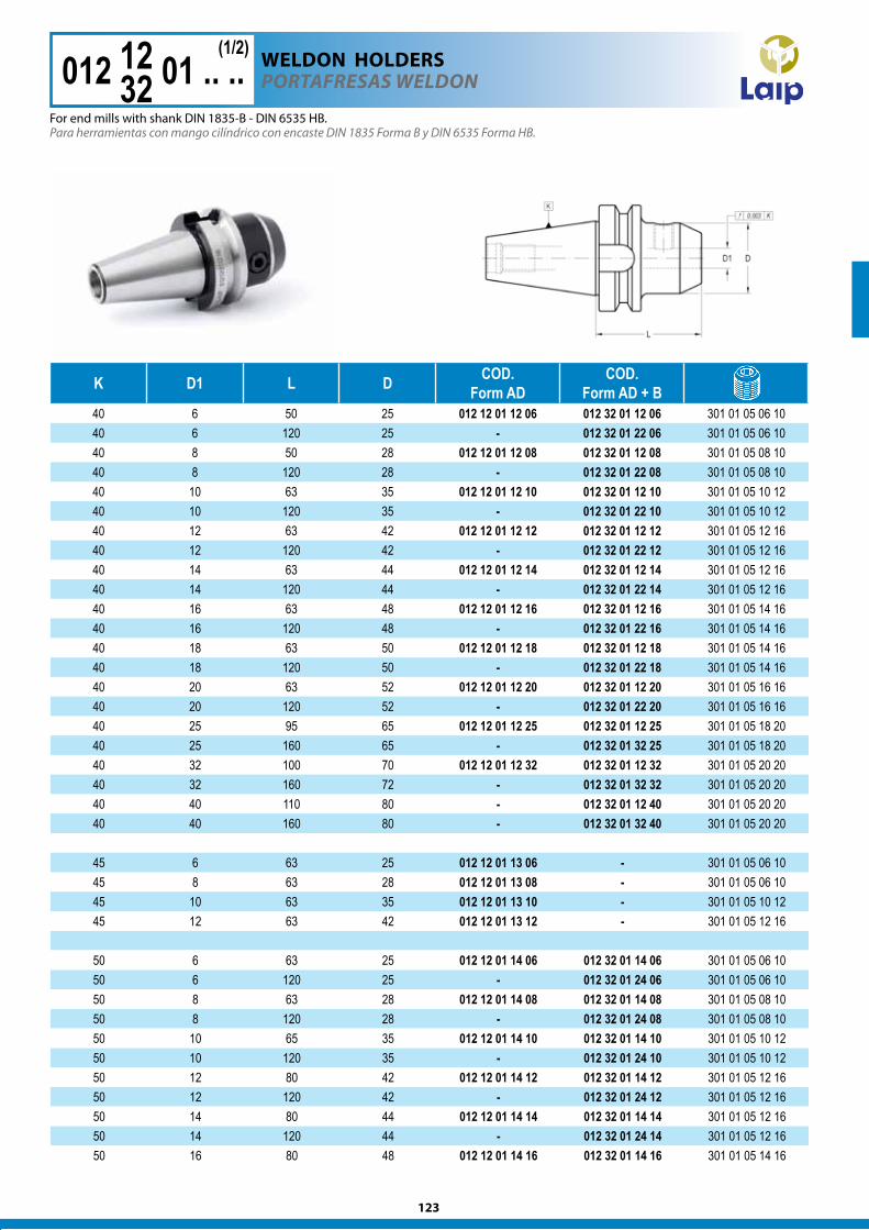
40 6 50 25 012 12 01 12 06 012 32 01 12 06 301 01 05 06 1040 6 120 25 - 012 32 01 22 06 301 01 05 06 1040 8 50 28 012 12 01 12 08 012 32 01 12 08 301 01 05 08 1040 8 120 28 - 012 32 01 22 08 301 01 05 08 1040 10 63 35 012 12 01 12 10 012 32 01 12 10 301 01 05 10 1240 10 120 35 - 012 32 01 22 10 301 01 05 10 1240 12 63 42 012 12 01 12 12 012 32 01 12 12 301 01 05 12 1640 12 120 42 - 012 32 01 22 12 301 01 05 12 1640 14 63 44 012 12 01 12 14 012 32 01 12 14 301 01 05 12 1640 14 120 44 - 012 32 01 22 14 301 01 05 12 1640 16 63 48 012 12 01 12 16 012 32 01 12 16 301 01 05 14 1640 16 120 48 - 012 32 01 22 16 301 01 05 14 1640 18 63 50 012 12 01 12 18 012 32 01 12 18 301 01 05 14 1640 18 120 50 - 012 32 01 22 18 301 01 05 14 1640 20 63 52 012 12 01 12 20 012 32 01 12 20 301 01 05 16 1640 20 120 52 - 012 32 01 22 20 301 01 05 16 1640 25 95 65 012 12 01 12 25 012 32 01 12 25 301 01 05 18 2040 25 160 65 - 012 32 01 32 25 301 01 05 18 2040 32 100 70 012 12 01 12 32 012 32 01 12 32 301 01 05 20 2040 32 160 72 - 012 32 01 32 32 301 01 05 20 2040 40 110 80 - 012 32 01 12 40 301 01 05 20 2040 40 160 80 - 012 32 01 32 40 301 01 05 20 20
45 6 63 25 012 12 01 13 06 - 301 01 05 06 1045 8 63 28 012 12 01 13 08 - 301 01 05 06 1045 10 63 35 012 12 01 13 10 - 301 01 05 10 1245 12 63 42 012 12 01 13 12 - 301 01 05 12 16
50 6 63 25 012 12 01 14 06 012 32 01 14 06 301 01 05 06 1050 6 120 25 - 012 32 01 24 06 301 01 05 06 1050 8 63 28 012 12 01 14 08 012 32 01 14 08 301 01 05 08 1050 8 120 28 - 012 32 01 24 08 301 01 05 08 1050 10 65 35 012 12 01 14 10 012 32 01 14 10 301 01 05 10 1250 10 120 35 - 012 32 01 24 10 301 01 05 10 1250 12 80 42 012 12 01 14 12 012 32 01 14 12 301 01 05 12 1650 12 120 42 - 012 32 01 24 12 301 01 05 12 1650 14 80 44 012 12 01 14 14 012 32 01 14 14 301 01 05 12 1650 14 120 44 - 012 32 01 24 14 301 01 05 12 1650 16 80 48 012 12 01 14 16 012 32 01 14 16 301 01 05 14 16
012 12 01 .. .. POrTafreSaS WeldON
Para herramientas con mango cilíndrico con encaste DIN 1835 Forma B y DIN 6535 Forma HB.
1232
(1/2)wElDOn hOlDERS
For end mills with shank DIN 1835-B - DIN 6535 HB.
124
K D1 L D COD. Form AD
COD. Form AD + B
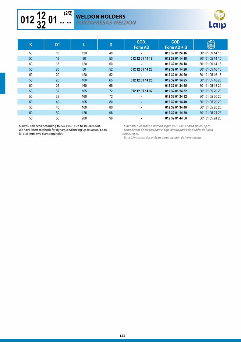
50 16 120 48 - 012 32 01 24 16 301 01 05 14 1650 18 80 50 012 12 01 14 18 012 32 01 14 18 301 01 05 14 1650 18 120 50 - 012 32 01 24 18 301 01 05 14 1650 20 80 52 012 12 01 14 20 012 32 01 14 20 301 01 05 16 1650 20 120 52 - 012 32 01 24 20 301 01 05 16 1650 25 100 65 012 12 01 14 25 012 32 01 14 25 301 01 05 18 2050 25 160 65 - 012 32 01 34 25 301 01 05 18 2050 32 105 72 012 12 01 14 32 012 32 01 14 32 301 01 05 20 2050 32 160 72 - 012 32 01 34 32 301 01 05 20 2050 40 105 80 - 012 32 01 14 40 301 01 05 20 2050 40 160 80 - 012 32 01 34 40 301 01 05 20 2050 50 125 98 - 012 32 01 14 50 301 01 05 24 2550 50 200 98 - 012 32 01 44 50 301 01 05 24 25
012 12 01 .. .. POrTafreSaS WeldON
- K30/K40 Equilibrado dinámico según ISO 1940-1 hasta 10.000 r.p.m. - Disponemos de medios para el equilibrado para velocidades de hasta 50.000 r.p.m.- D1 ≥ 25mm: con dos orificios para sujección de herramienta.
1232
(2/2)wElDOn hOlDERS
- K 30/40 Balanced according to ISO 1940-1 up to 10.000 r.p.m. - We have latest methods for dynamic balancing up to 50.000 r.p.m.- D1≥ 25 mm: two clamping holes.
125
K D1 L D COD. Form AD
COD. Form AD + B
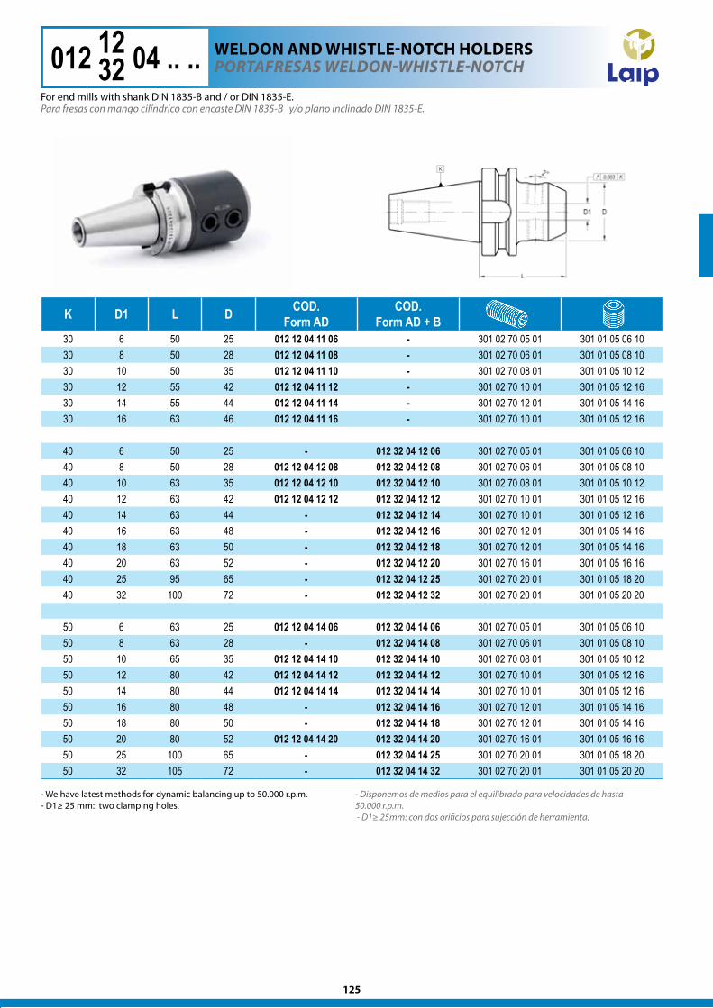
30 6 50 25 012 12 04 11 06 - 301 02 70 05 01 301 01 05 06 1030 8 50 28 012 12 04 11 08 - 301 02 70 06 01 301 01 05 08 1030 10 50 35 012 12 04 11 10 - 301 02 70 08 01 301 01 05 10 1230 12 55 42 012 12 04 11 12 - 301 02 70 10 01 301 01 05 12 1630 14 55 44 012 12 04 11 14 - 301 02 70 12 01 301 01 05 14 1630 16 63 46 012 12 04 11 16 - 301 02 70 10 01 301 01 05 12 16
40 6 50 25 - 012 32 04 12 06 301 02 70 05 01 301 01 05 06 1040 8 50 28 012 12 04 12 08 012 32 04 12 08 301 02 70 06 01 301 01 05 08 1040 10 63 35 012 12 04 12 10 012 32 04 12 10 301 02 70 08 01 301 01 05 10 1240 12 63 42 012 12 04 12 12 012 32 04 12 12 301 02 70 10 01 301 01 05 12 1640 14 63 44 - 012 32 04 12 14 301 02 70 10 01 301 01 05 12 1640 16 63 48 - 012 32 04 12 16 301 02 70 12 01 301 01 05 14 1640 18 63 50 - 012 32 04 12 18 301 02 70 12 01 301 01 05 14 1640 20 63 52 - 012 32 04 12 20 301 02 70 16 01 301 01 05 16 1640 25 95 65 - 012 32 04 12 25 301 02 70 20 01 301 01 05 18 2040 32 100 72 - 012 32 04 12 32 301 02 70 20 01 301 01 05 20 20
50 6 63 25 012 12 04 14 06 012 32 04 14 06 301 02 70 05 01 301 01 05 06 1050 8 63 28 - 012 32 04 14 08 301 02 70 06 01 301 01 05 08 1050 10 65 35 012 12 04 14 10 012 32 04 14 10 301 02 70 08 01 301 01 05 10 1250 12 80 42 012 12 04 14 12 012 32 04 14 12 301 02 70 10 01 301 01 05 12 1650 14 80 44 012 12 04 14 14 012 32 04 14 14 301 02 70 10 01 301 01 05 12 1650 16 80 48 - 012 32 04 14 16 301 02 70 12 01 301 01 05 14 1650 18 80 50 - 012 32 04 14 18 301 02 70 12 01 301 01 05 14 1650 20 80 52 012 12 04 14 20 012 32 04 14 20 301 02 70 16 01 301 01 05 16 1650 25 100 65 - 012 32 04 14 25 301 02 70 20 01 301 01 05 18 2050 32 105 72 - 012 32 04 14 32 301 02 70 20 01 301 01 05 20 20
Para fresas con mango cilíndrico con encaste DIN 1835-B y/o plano inclinado DIN 1835-E.
- Disponemos de medios para el equilibrado para velocidades de hasta 50.000 r.p.m. - D1≥ 25mm: con dos orificios para sujección de herramienta.
POrTafreSaS WeldON-WhISTle-NOTCh 012 12 04 .. ..1232
- We have latest methods for dynamic balancing up to 50.000 r.p.m.- D1≥ 25 mm: two clamping holes.
For end mills with shank DIN 1835-B and / or DIN 1835-E.
wElDOn AnD whISTlE-nOTch hOlDERS
126
K D1 L D COD.Form A
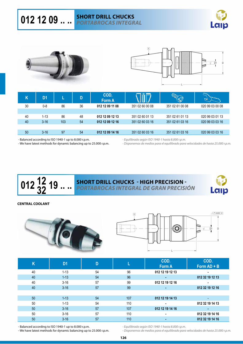
30 0-8 86 36 012 12 09 11 08 351 02 60 00 08 351 02 61 00 08 020 99 03 00 08
40 1-13 86 48 012 12 09 12 13 351 02 60 01 13 351 02 61 01 13 020 99 03 01 1340 3-16 103 54 012 12 09 12 16 351 02 60 03 16 351 02 61 03 16 020 99 03 03 16
50 3-16 97 54 012 12 09 14 16 351 02 60 03 16 351 02 61 03 16 020 99 03 03 16
012 12 09 .. .. POrTaBrOCaS INTegral
- Equilibrado según ISO 1940-1 hasta 8.000 r.p.m. - Disponemos de medios para el equilibrado para velocidades de hasta 25.000 r.p.m.
- Equilibrado según ISO 1940-1 hasta 8.000 r.p.m. - Disponemos de medios para el equilibrado para velocidades de hasta 25.000 r.p.m.
K D1 D L COD. Form A
COD. Form AD + B
40 1-13 54 96 012 12 19 12 13 -40 1-13 54 96 - 012 32 19 12 1340 3-16 57 99 012 12 19 12 16 -40 3-16 57 99 - 012 32 19 12 16
50 1-13 54 107 012 12 19 14 13 -50 1-13 54 110 - 012 32 19 14 1350 3-16 57 107 012 12 19 14 16 -50 3-16 57 110 - 012 32 19 14 1650 3-16 57 110 - 012 32 19 14 16
012 12 19 .. .. POrTaBrOCaS INTegral de graN PreCISIóN
cEnTRAl cOOlAnT
1232
ShORT DRIll chUckS - hIgh PREcISIOn -
ShORT DRIll chUckS
- Balanced according to ISO 1940-1 up to 8.000 r.p.m. - We have latest methods for dynamic balancing up to 25.000 r.p.m.
- Balanced according to ISO 1940-1 up to 8.000 r.p.m. - We have latest methods for dynamic balancing up to 25.000 r.p.m.
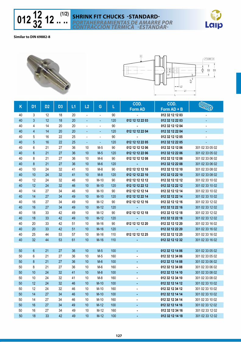
127
K D1 D2 D3 L1 L2 G L COD.Form AD
COD. Form AD + B
40 3 12 18 20 - - 90 - 012 32 12 12 03 -40 3 12 18 20 - - 120 012 12 12 22 03 012 32 12 22 03 -40 4 14 20 20 - - 90 - 012 32 12 12 04 -40 4 14 20 20 - - 120 012 12 12 22 04 012 32 12 22 04 -40 5 16 22 25 - - 90 - 012 32 12 12 05 -40 5 16 22 25 - - 120 012 12 12 22 05 012 32 12 22 05 -40 6 21 27 36 10 M-5 90 012 12 12 12 06 012 32 12 12 06 301 02 33 05 0240 6 21 27 36 10 M-5 120 012 12 12 22 06 012 32 12 22 06 301 02 33 05 0240 8 21 27 36 10 M-6 90 012 12 12 12 08 012 32 12 12 08 301 02 33 06 0240 8 21 27 36 10 M-6 120 - 012 32 12 22 08 301 02 33 06 0240 10 24 32 41 10 M-8 90 012 12 12 12 10 012 32 12 12 10 301 02 33 08 0240 10 24 32 41 10 M-8 120 012 12 12 22 10 012 32 12 22 10 301 02 33 08 0240 12 24 32 46 10 M-10 90 012 12 12 12 12 012 32 12 12 12 301 02 33 10 0240 12 24 32 46 10 M-10 120 012 12 12 22 12 012 32 12 22 12 301 02 33 10 0240 14 27 34 46 10 M-10 90 012 12 12 12 14 012 32 12 12 14 301 02 33 10 0240 14 27 34 49 10 M-10 120 012 12 12 22 14 012 32 12 22 14 301 02 33 10 0240 16 27 34 49 10 M-12 90 012 12 12 12 16 012 32 12 12 16 301 02 33 12 0240 16 27 34 49 10 M-12 120 - 012 32 12 22 16 301 02 33 12 0240 18 33 42 49 10 M-12 90 012 12 12 12 18 012 32 12 12 18 301 02 33 12 0240 18 33 42 49 10 M-12 120 - 012 32 12 22 18 301 02 33 12 0240 20 33 42 51 10 M-16 90 012 12 12 12 20 012 32 12 12 20 301 02 33 16 0240 20 33 42 51 10 M-16 120 - 012 32 12 22 20 301 02 33 16 0240 25 44 53 57 10 M-16 110 012 12 12 12 25 012 32 12 12 25 301 02 33 16 0240 32 44 53 61 10 M-16 110 - 012 32 12 12 32 301 02 33 16 02
50 6 21 27 36 10 M-5 100 - 012 32 12 14 06 301 02 33 05 0250 6 21 27 36 10 M-5 160 - 012 32 12 34 06 301 02 33 05 0250 8 21 27 36 10 M-6 100 - 012 32 12 14 08 301 02 33 06 0250 8 21 27 36 10 M-6 160 - 012 32 12 34 08 301 02 33 06 0250 10 24 32 41 10 M-8 100 - 012 32 12 14 10 301 02 33 08 0250 10 24 32 41 10 M-8 160 - 012 32 12 34 10 301 02 33 08 0250 12 24 32 46 10 M-10 100 - 012 32 12 14 12 301 02 33 10 0250 12 24 32 46 10 M-10 160 - 012 32 12 34 12 301 02 33 10 0250 14 27 34 46 10 M-10 100 - 012 32 12 14 14 301 02 33 10 0250 14 27 34 46 10 M-10 160 - 012 32 12 34 14 301 02 33 10 0250 16 27 34 49 10 M-12 100 - 012 32 12 14 16 301 02 33 12 0250 16 27 34 49 10 M-12 160 - 012 32 12 34 16 301 02 33 12 0250 18 33 42 49 10 M-12 100 - 012 32 12 14 18 301 02 33 12 02
Similar to DIn 69882-8
012 12 12 .. ..1232
(1/2)POrTaherraMIeNTaS de aMarre POr CONTraCCIóN TérMICa -eSTaNdar-
ShRInk FIT chUckS -STAnDARD-
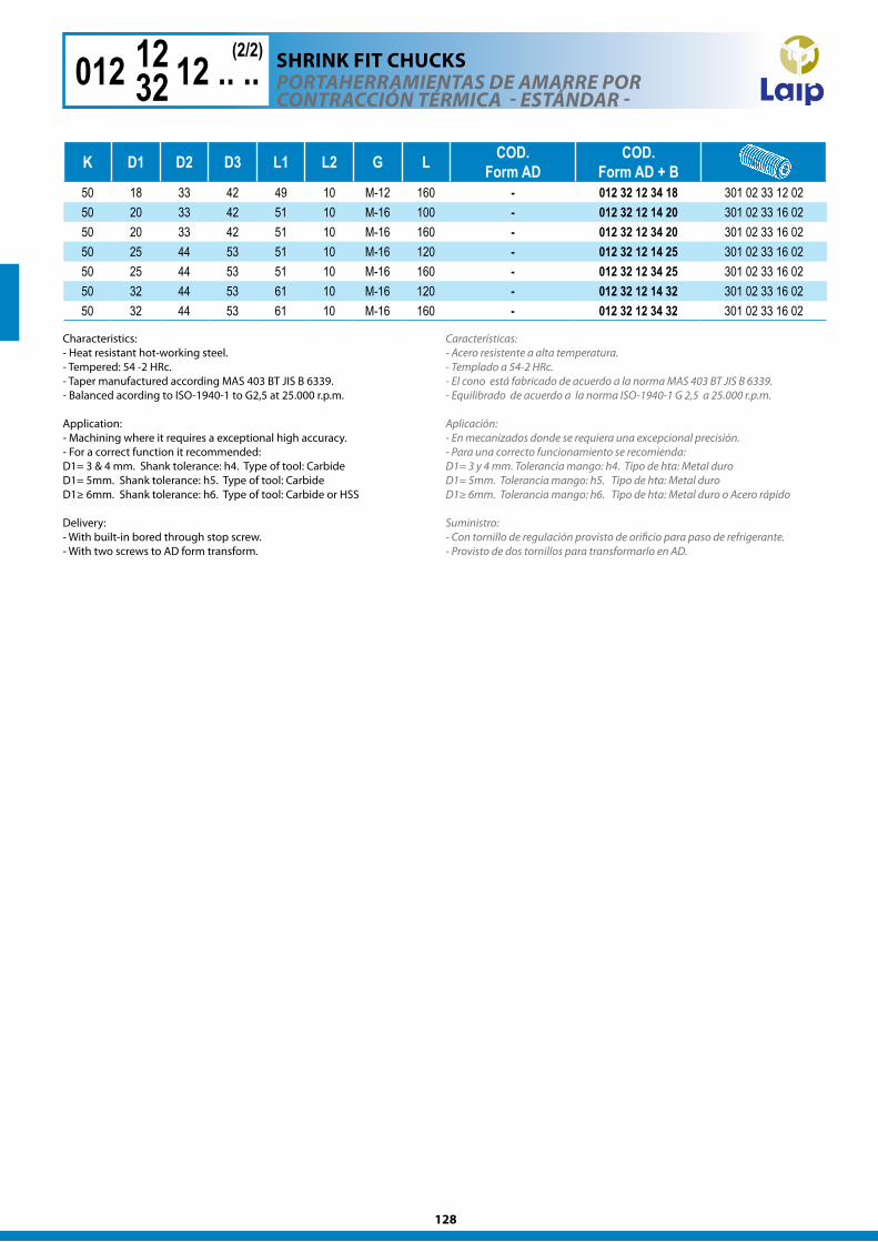
128
K D1 D2 D3 L1 L2 G L COD.Form AD
COD. Form AD + B
50 18 33 42 49 10 M-12 160 - 012 32 12 34 18 301 02 33 12 0250 20 33 42 51 10 M-16 100 - 012 32 12 14 20 301 02 33 16 0250 20 33 42 51 10 M-16 160 - 012 32 12 34 20 301 02 33 16 0250 25 44 53 51 10 M-16 120 - 012 32 12 14 25 301 02 33 16 0250 25 44 53 51 10 M-16 160 - 012 32 12 34 25 301 02 33 16 0250 32 44 53 61 10 M-16 120 - 012 32 12 14 32 301 02 33 16 0250 32 44 53 61 10 M-16 160 - 012 32 12 34 32 301 02 33 16 02
POrTaherraMIeNTaS de aMarre POr CONTraCCIóN TérMICa - eSTÁNdar -
012 12 12 .. ..1232
(2/2)
Características:- Acero resistente a alta temperatura. - Templado a 54-2 HRc.- El cono está fabricado de acuerdo a la norma MAS 403 BT JIS B 6339.- Equilibrado de acuerdo a la norma ISO-1940-1 G 2,5 a 25.000 r.p.m.
Aplicación:- En mecanizados donde se requiera una excepcional precisión.- Para una correcto funcionamiento se recomienda:D1= 3 y 4 mm. Tolerancia mango: h4. Tipo de hta: Metal duroD1= 5mm. Tolerancia mango: h5. Tipo de hta: Metal duroD1≥ 6mm. Tolerancia mango: h6. Tipo de hta: Metal duro o Acero rápido
Suministro: - Con tornillo de regulación provisto de orificio para paso de refrigerante.- Provisto de dos tornillos para transformarlo en AD.
Characteristics: - Heat resistant hot-working steel.- Tempered: 54 -2 HRc. - Taper manufactured according MAS 403 BT JIS B 6339.- Balanced acording to ISO-1940-1 to G2,5 at 25.000 r.p.m.
Application: - Machining where it requires a exceptional high accuracy. - For a correct function it recommended:D1= 3 & 4 mm. Shank tolerance: h4. Type of tool: CarbideD1= 5mm. Shank tolerance: h5. Type of tool: CarbideD1≥ 6mm. Shank tolerance: h6. Type of tool: Carbide or HSS
Delivery: - With built-in bored through stop screw.- With two screws to AD form transform.
ShRInk FIT chUckS
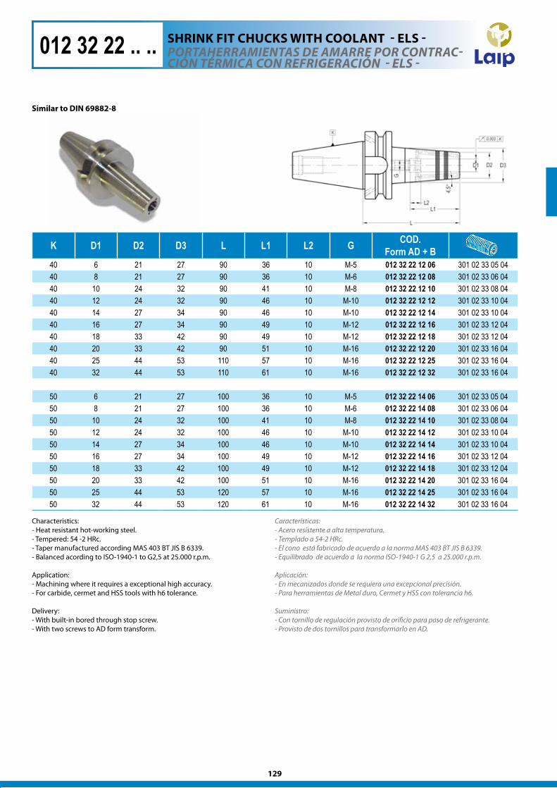
129
K D1 D2 D3 L L1 L2 G COD. Form AD + B
40 6 21 27 90 36 10 M-5 012 32 22 12 06 301 02 33 05 0440 8 21 27 90 36 10 M-6 012 32 22 12 08 301 02 33 06 0440 10 24 32 90 41 10 M-8 012 32 22 12 10 301 02 33 08 0440 12 24 32 90 46 10 M-10 012 32 22 12 12 301 02 33 10 0440 14 27 34 90 46 10 M-10 012 32 22 12 14 301 02 33 10 0440 16 27 34 90 49 10 M-12 012 32 22 12 16 301 02 33 12 0440 18 33 42 90 49 10 M-12 012 32 22 12 18 301 02 33 12 0440 20 33 42 90 51 10 M-16 012 32 22 12 20 301 02 33 16 0440 25 44 53 110 57 10 M-16 012 32 22 12 25 301 02 33 16 0440 32 44 53 110 61 10 M-16 012 32 22 12 32 301 02 33 16 04
50 6 21 27 100 36 10 M-5 012 32 22 14 06 301 02 33 05 0450 8 21 27 100 36 10 M-6 012 32 22 14 08 301 02 33 06 0450 10 24 32 100 41 10 M-8 012 32 22 14 10 301 02 33 08 0450 12 24 32 100 46 10 M-10 012 32 22 14 12 301 02 33 10 0450 14 27 34 100 46 10 M-10 012 32 22 14 14 301 02 33 10 0450 16 27 34 100 49 10 M-12 012 32 22 14 16 301 02 33 12 0450 18 33 42 100 49 10 M-12 012 32 22 14 18 301 02 33 12 0450 20 33 42 100 51 10 M-16 012 32 22 14 20 301 02 33 16 0450 25 44 53 120 57 10 M-16 012 32 22 14 25 301 02 33 16 0450 32 44 53 120 61 10 M-16 012 32 22 14 32 301 02 33 16 04
Similar to DIn 69882-8
Características:- Acero resistente a alta temperatura. - Templado a 54-2 HRc. - El cono está fabricado de acuerdo a la norma MAS 403 BT JIS B 6339.- Equilibrado de acuerdo a la norma ISO-1940-1 G 2,5 a 25.000 r.p.m.
Aplicación:- En mecanizados donde se requiera una excepcional precisión.- Para herramientas de Metal duro, Cermet y HSS con tolerancia h6.
Suministro:- Con tornillo de regulación provisto de orificio para paso de refrigerante.- Provisto de dos tornillos para transformarlo en AD.
POrTaherraMIeNTaS de aMarre POr CONTraC-CIóN TérMICa CON refrIgeraCIóN - elS -
012 32 22 .. ..
Characteristics: - Heat resistant hot-working steel.- Tempered: 54 -2 HRc. - Taper manufactured according MAS 403 BT JIS B 6339.- Balanced acording to ISO-1940-1 to G2,5 at 25.000 r.p.m.
Application: - Machining where it requires a exceptional high accuracy. - For carbide, cermet and HSS tools with h6 tolerance.
Delivery: - With built-in bored through stop screw. - With two screws to AD form transform.
ShRInk FIT chUckS wITh cOOlAnT - ElS -
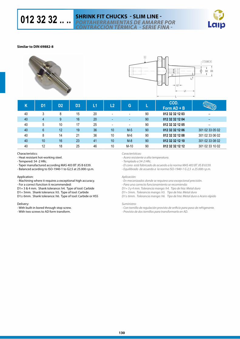
130
K D1 D2 D3 L1 L2 G L COD. Form AD + B
40 3 8 15 20 - - 90 012 32 32 12 03 –40 4 9 16 20 - - 90 012 32 32 12 04 –40 5 10 17 25 - - 90 012 32 32 12 05 –40 6 12 19 36 10 M-5 90 012 32 32 12 06 301 02 33 05 0240 8 14 21 36 10 M-6 90 012 32 32 12 08 301 02 33 06 0240 10 16 23 41 10 M-8 90 012 32 32 12 10 301 02 33 08 0240 12 18 25 46 10 M-10 90 012 32 32 12 12 301 02 33 10 02
012 32 32 .. .. POrTaherraMIeNTaS de aMarre POr CONTraCCIóN TérMICa - SerIe fINa -
Similar to DIn 69882-8
ShRInk FIT chUckS - SlIM lInE -
Características:- Acero resistente a alta temperatura. - Templado a 54-2 HRc.- El cono está fabricado de acuerdo a la norma MAS 403 BT JIS B 6339.- Equilibrado de acuerdo a la norma ISO-1940-1 G 2,5 a 25.000 r.p.m.
Aplicación:- En mecanizados donde se requiera una excepcional precisión.- Para una correcto funcionamiento se recomienda:D1= 3 y 4 mm. Tolerancia mango: h4. Tipo de hta: Metal duroD1= 5mm. Tolerancia mango: h5. Tipo de hta: Metal duroD1≥ 6mm. Tolerancia mango: h6. Tipo de hta: Metal duro o Acero rápido
Suministro: - Con tornillo de regulación provisto de orificio para paso de refrigerante.- Provisto de dos tornillos para transformarlo en AD.
Characteristics: - Heat resistant hot-working steel.- Tempered: 54 -2 HRc. - Taper manufactured according MAS 403 BT JIS B 6339.- Balanced acording to ISO-1940-1 to G2,5 at 25.000 r.p.m.
Application: - Machining where it requires a exceptional high accuracy. - For a correct function it recommended:D1= 3 & 4 mm. Shank tolerance: h4. Type of tool: CarbideD1= 5mm. Shank tolerance: h5. Type of tool: CarbideD1≥ 6mm. Shank tolerance: h6. Type of tool: Carbide or HSS
Delivery: - With built-in bored through stop screw.- With two screws to AD form transform.
131
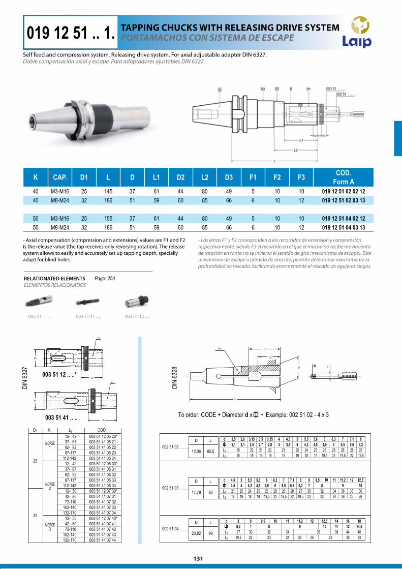
K CAP. D1 L D L1 D2 L2 D3 F1 F2 F3 COD. Form A
40 M3-M16 25 145 37 61 44 80 49 5 10 10 019 12 51 02 02 1240 M8-M24 32 186 51 59 60 85 66 6 10 12 019 12 51 02 03 13
50 M3-M16 25 155 37 61 44 80 49 5 10 10 019 12 51 04 02 1250 M8-M24 32 186 51 59 60 85 66 6 10 12 019 12 51 04 03 13
Doble compensación axial y escape. Para adaptadores ajustables DIN 6327.
- Las letras F1 y F2 corresponden a los recorridos de extensión y comprensión respectivamente, siendo F3 el recorrido en el que el macho no recibe movimiento de rotación en tanto no se invierta el sentido de giro (mecanismo de escape). Este mecanismo de escape o pérdida de arrastre, permite determinar exactamente la profundidad de roscado, facilitando enormemente el roscado de agujeros ciegos.
POrTaMaChOS CON SISTeMa de eSCaPe
002 51 .. .. .. 003 51 12 .. ..
ELEMENTOS RELACIONADOSRELATIONATED ELEMENTS
019 12 51 .. 1.
003 51 41 .. ..
Page: 259
- Axial compensation (compression and extensions) values are F1 and F2 is the release value (the tap receives only reversing rotation). The release system allows to easily and accurately set up tapping depth, specially adapt for blind holes.
Self feed and compression system. Releasing drive system. For axial adjustable adapter DIN 6327.
TAPPIng chUckS wITh RElEASIng DRIvE SySTEM
132
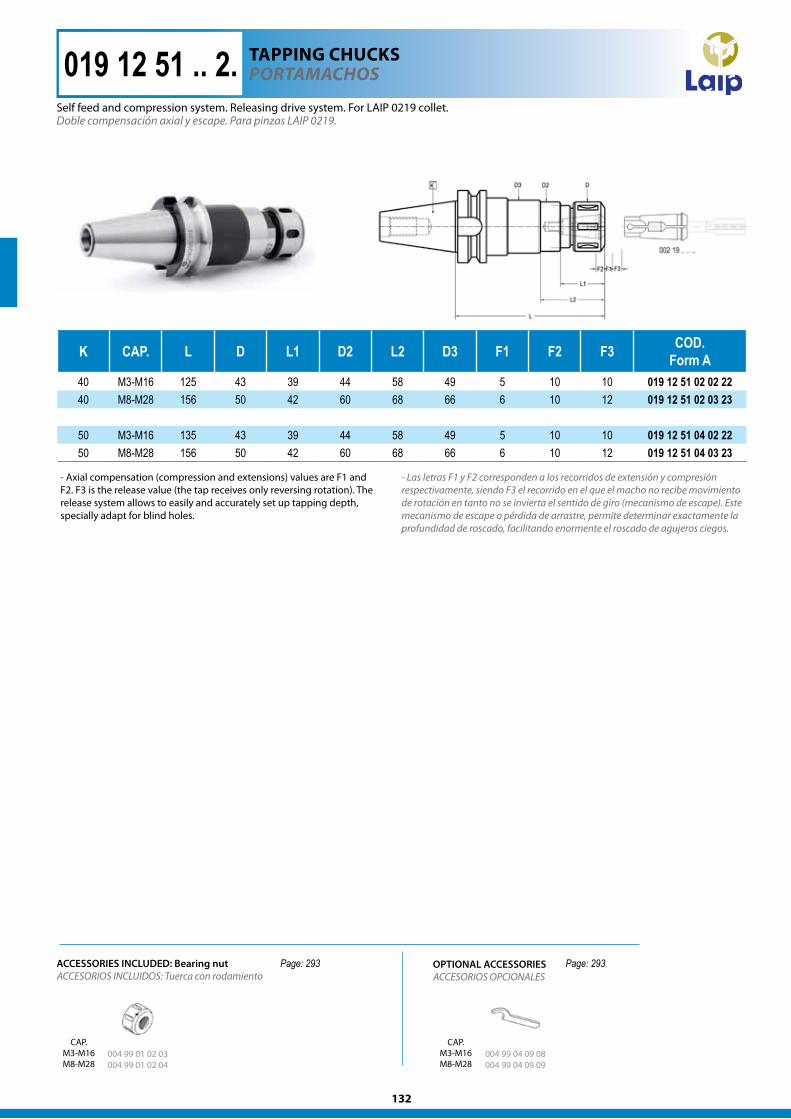
K CAP. L D L1 D2 L2 D3 F1 F2 F3 COD. Form A
40 M3-M16 125 43 39 44 58 49 5 10 10 019 12 51 02 02 2240 M8-M28 156 50 42 60 68 66 6 10 12 019 12 51 02 03 23
50 M3-M16 135 43 39 44 58 49 5 10 10 019 12 51 04 02 2250 M8-M28 156 50 42 60 68 66 6 10 12 019 12 51 04 03 23
019 12 51 .. 2. POrTaMaChOS
Doble compensación axial y escape. Para pinzas LAIP 0219.
- Las letras F1 y F2 corresponden a los recorridos de extensión y compresión respectivamente, siendo F3 el recorrido en el que el macho no recibe movimiento de rotación en tanto no se invierta el sentido de giro (mecanismo de escape). Este mecanismo de escape o pérdida de arrastre, permite determinar exactamente la profundidad de roscado, facilitando enormente el roscado de agujeros ciegos.
Page: 293 Page: 293
TAPPIng chUckS
Self feed and compression system. Releasing drive system. For LAIP 0219 collet.
- Axial compensation (compression and extensions) values are F1 and F2. F3 is the release value (the tap receives only reversing rotation). The release system allows to easily and accurately set up tapping depth, specially adapt for blind holes.
OPTIONAL ACCESSORIESACCESORIOS OPCIONALES
004 99 01 02 03 004 99 01 02 04
004 99 04 09 08 004 99 04 09 09
CAP.M3-M16M8-M28
CAP.M3-M16M8-M28
ACCESORIOS INCLUIDOS: Tuerca con rodamientoACCESSORIES INCLUDED: Bearing nut
133
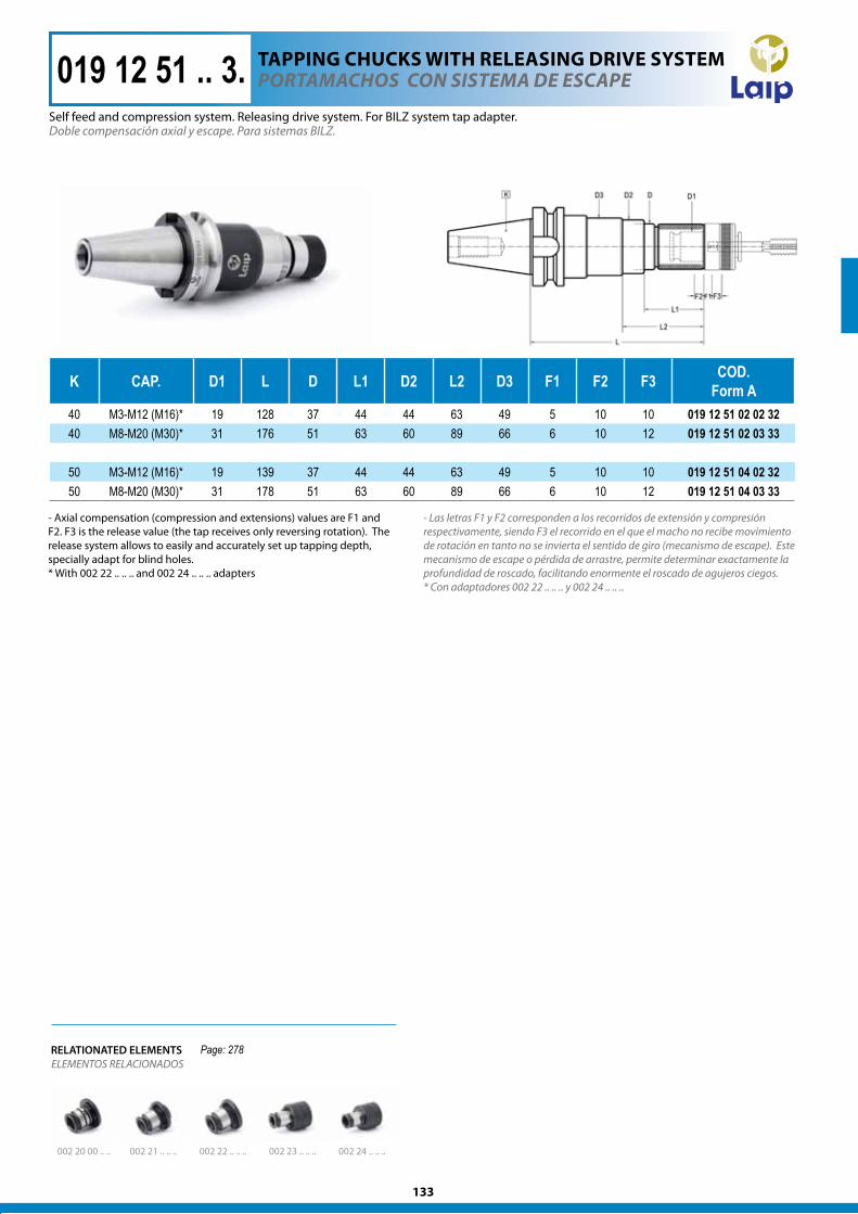
K CAP. D1 L D L1 D2 L2 D3 F1 F2 F3 COD. Form A
40 M3-M12 (M16)* 19 128 37 44 44 63 49 5 10 10 019 12 51 02 02 3240 M8-M20 (M30)* 31 176 51 63 60 89 66 6 10 12 019 12 51 02 03 33
50 M3-M12 (M16)* 19 139 37 44 44 63 49 5 10 10 019 12 51 04 02 3250 M8-M20 (M30)* 31 178 51 63 60 89 66 6 10 12 019 12 51 04 03 33
Doble compensación axial y escape. Para sistemas BILZ.
- Las letras F1 y F2 corresponden a los recorridos de extensión y compresión respectivamente, siendo F3 el recorrido en el que el macho no recibe movimiento de rotación en tanto no se invierta el sentido de giro (mecanismo de escape). Este mecanismo de escape o pérdida de arrastre, permite determinar exactamente la profundidad de roscado, facilitando enormente el roscado de agujeros ciegos.* Con adaptadores 002 22 .. .. .. y 002 24 .. .. ..
POrTaMaChOS CON SISTeMa de eSCaPe019 12 51 .. 3.
002 20 00 .. .. 002 21 .. .. .. 002 22 .. .. ..
ELEMENTOS RELACIONADOSRELATIONATED ELEMENTS
002 23 .. .. .. 002 24 .. .. ..
Page: 278
- Axial compensation (compression and extensions) values are F1 and F2. F3 is the release value (the tap receives only reversing rotation). The release system allows to easily and accurately set up tapping depth, specially adapt for blind holes.* With 002 22 .. .. .. and 002 24 .. .. .. adapters
Self feed and compression system. Releasing drive system. For BILZ system tap adapter.
TAPPIng chUckS wITh RElEASIng DRIvE SySTEM
134
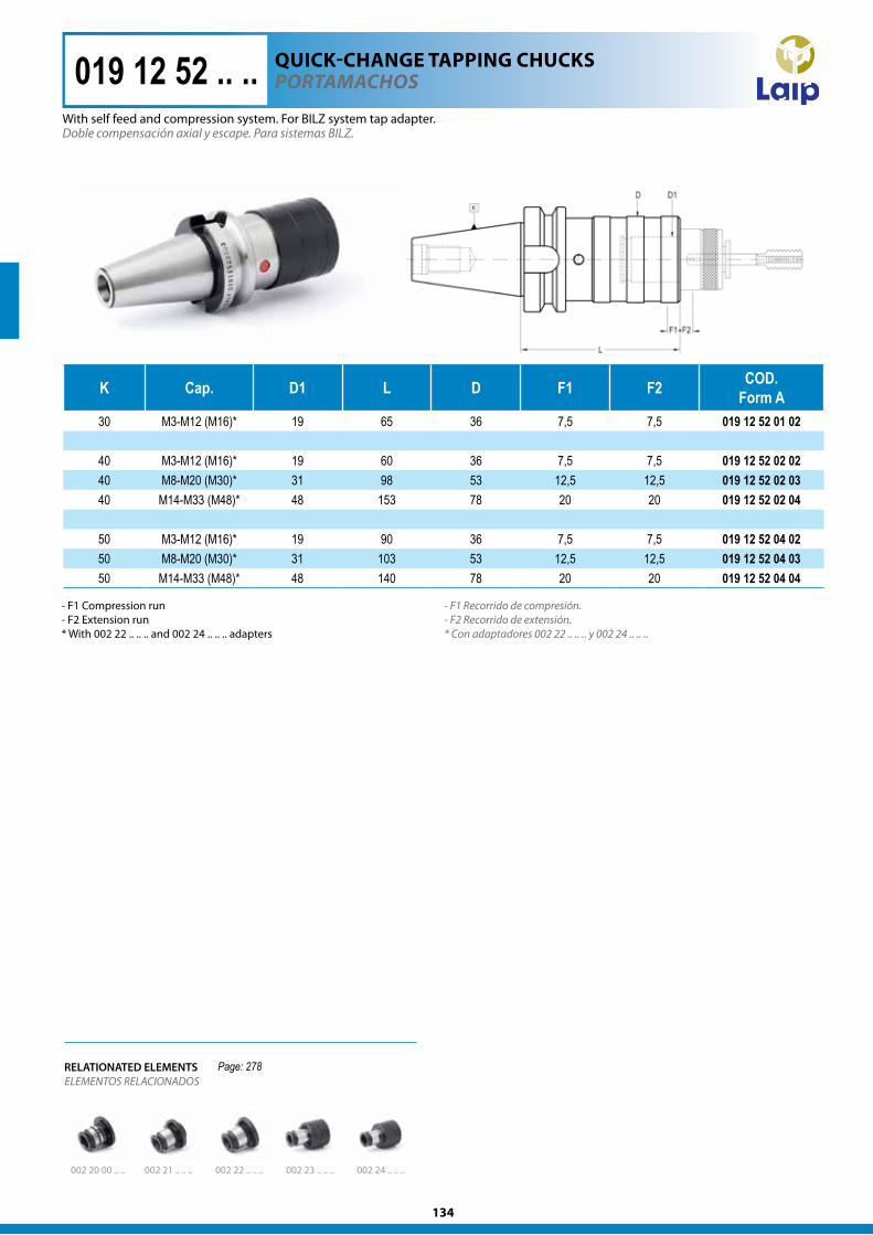
K Cap. D1 L D F1 F2 COD.Form A
30 M3-M12 (M16)* 19 65 36 7,5 7,5 019 12 52 01 02
40 M3-M12 (M16)* 19 60 36 7,5 7,5 019 12 52 02 0240 M8-M20 (M30)* 31 98 53 12,5 12,5 019 12 52 02 0340 M14-M33 (M48)* 48 153 78 20 20 019 12 52 02 04
50 M3-M12 (M16)* 19 90 36 7,5 7,5 019 12 52 04 0250 M8-M20 (M30)* 31 103 53 12,5 12,5 019 12 52 04 0350 M14-M33 (M48)* 48 140 78 20 20 019 12 52 04 04
019 12 52 .. .. POrTaMaChOS
Doble compensación axial y escape. Para sistemas BILZ.
- F1 Recorrido de compresión.- F2 Recorrido de extensión.* Con adaptadores 002 22 .. .. .. y 002 24 .. .. ..
RELATIONATED ELEMENTSELEMENTOS RELACIONADOS
002 24 .. .. ..002 23 .. .. ..002 22 .. .. ..002 21 .. .. ..002 20 00 .. ..
Page: 278
QUIck-chAngE TAPPIng chUckS
With self feed and compression system. For BILZ system tap adapter.
- F1 Compression run- F2 Extension run * With 002 22 .. .. .. and 002 24 .. .. .. adapters
135
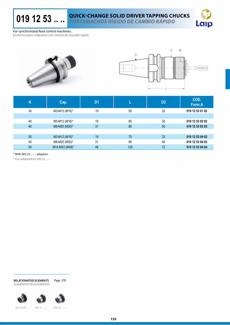
K Cap. D1 L D2 COD. Form A
30 M3-M12 (M16)* 19 55 32 019 12 53 01 02
40 M3-M12 (M16)* 19 65 32 019 12 53 02 0240 M8-M20 (M30)* 31 85 50 019 12 53 02 03
50 M3-M12 (M16)* 19 75 32 019 12 53 04 0250 M8-M20 (M30)* 31 95 50 019 12 53 04 0350 M14-M33 (M48)* 48 125 72 019 12 53 04 04
Exclusivo para máquinas con control de roscado rígido.
* Con adaptadores 002 22 .. .. ..
POrTaMaChOS rÍgIdO de CaMBIO rÁPIdO
002 20 00 .. .. 002 21 .. .. .. 002 22 .. .. ..
ELEMENTOS RELACIONADOSRELATIONATED ELEMENTS
019 12 53 .. ..
Page: 278
* With 002 22 .. .. .. adapters.
For synchronized feed control machines.
QUIck-chAngE SOlID DRIvER TAPPIng chUckS
136
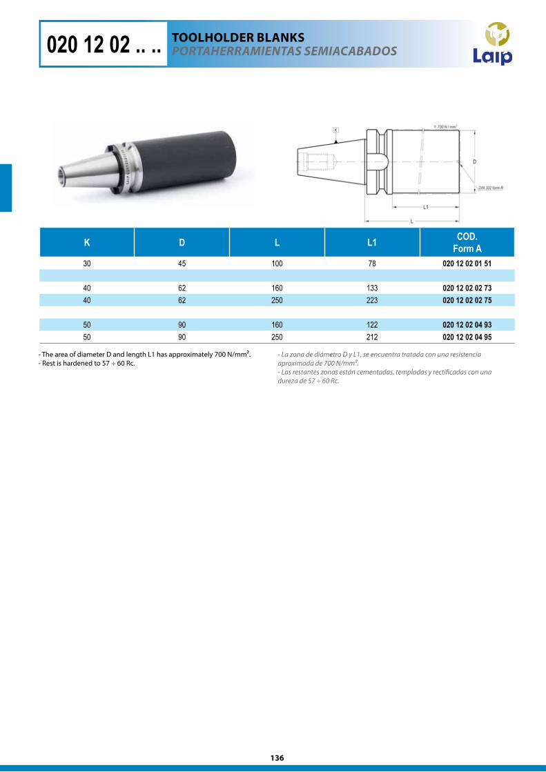
K D L L1 COD.Form A
30 45 100 78 020 12 02 01 51
40 62 160 133 020 12 02 02 7340 62 250 223 020 12 02 02 75
50 90 160 122 020 12 02 04 9350 90 250 212 020 12 02 04 95
020 12 02 .. .. POrTaherraMIeNTaS SeMIaCaBadOS
- La zona de diámetro D y L1, se encuentra tratada con una resistencia aproximada de 700 N/mm².- Las restantes zonas están cementadas, templadas y rectificadas con una dureza de 57 ÷ 60 Rc.
TOOlhOlDER BlAnkS
- The area of diameter D and length L1 has approximately 700 N/mm². - Rest is hardened to 57 ÷ 60 Rc.