universidad de cantabria - bibliotecadigital.ipb.pt · jornada t ecnica lnternacional los modelos...
TRANSCRIPT
uc ' ! (1""-- :: ~ ; { \' ' ..... :-...\. \>· ...,_ .. , ...... ,,, \. , __ •, • ' · I\ \
\ \. ' ... - ... I I I 11<-- '·- 1 / I \ 1-- · • ' I I . . ' . ..... \_ '
UNIVERSIDAD DE CANTABRIA
Jornada T ecnica lnternacional
Los Modelos de Simulaci6n Computacional en la lngenieria y la lnvestigaci6n de lncendios.
Computational Simulation Models in Fire Engineering and Research
Editado por: Prof. Jorge A Capote Abreu
Compilado por: D. Daniel Alvear Portilla D. Guillermo Herrera del Campo
Esta Jornada Tecnica lnternacional fue organizada por: GIDAI - Grupo de lnvestigaci6n y Desarrollo de Actuaciones Industriales UNIVERSIDAD DE CANTABRIA Dpto. de Transportes y Tecnologfa de Proyectos y Procesos Avda. Los Castros, sin 39005 Santander. Espana Tf. + 34 942 201826. Fax. +34 942 201873. [email protected] http://grupos.unican.es/GIDAI
En colaboraci6n con:
University of Edinburgh (UK) Politecnico di Bari (/!alia)
Participan y Colaboran:
Gobierno de Cantabria
Ayuntamiento de Santander
Universidad de Cantabria
Camara de Comercio
Fundaci6n Leonardo Torres Quevedo
National Fire Protection Association- NFPA
Society of Fire Protection Engineers- SFPE
Jornada Tecnica lnternacional subvencionada por:
MINISTERIO DE EDUCACION Y CIENCIA
University of California, Berkeley (USA)
University of Southern Mississippi (USA)
International Association for Fire Safety Science -IAFSS
Cementos Alfa
El Diario Montanes
Colegios Profesionales de Cantabria
Asociaci6n Profesional de lngenieros Contra lncendios - APICI
Promat lberica, SA
CSN CONSEjO DE SEGUR DAD NUCLEAR
CONSEJO DE SEGURIDAD NUCLEAR
El editor no asume responsabilidad ninguna sabre la actualidad, correctitud, e/ estado completo o la calidad de /as informaciones puestas a disposici6n. El uso no autorizado puede infringir Ios derechos de propiedad de patentes de la publicaci6n.
Ninguna responsabilidad es asumida por el editor por cualquier dafio a /as personas o a la propiedad coma consecuencia de productos o servicios prestados u ofertados par otras personas o entidades, y otros derivados de la operaci6n de a/gun metodo, intrucciones o ideas contenidas a continuaci6n.
ISBN 84-8102-383-3 DEPOSITO LEGAL SA-1427-2004
lmprime: Graficas lgufia, SA

Ponencias de la Jornada Tecnica lnternacional "Los Mode/os de Simulaci6n Computacional en la lngenieria y la lnvestigaci6n de /ncendios"
Presentacion
La Jornada Tecnica Intemacional sobre "LOS MODELOS DE SIMULACION COMPUTACIONAL EN LA INGENIERIA Y LA INVESTIGACION DE INCENDIOS", cuyo Libro de Ponencias presentamos, se celebr6 en la Escuela de Ingenieros Industriales y de Telecomunicaci6n de la Universidad de Cantabria, Santander, Cantabria, Espafia el 20 de Octubre de 2004.
Ha sido una oportunidad (mica para investigadores, ingenieros especializados en seguridad contra
incendios, analistas de riesgos de incendios, y otras muchas disciplinas afines a la Ciencia y la
Tecnologia del Incendio para aproximarse mas a lo que sin duda vienen siendo !as herramientas mas
validas en la Ingenieria de la Seguridad contra Incendios: LOS MODELOS DE SIMULACION
COMPUTACIONAL.
A la Jornada se presentaron 23 ponencias en representaci6n de 11 paises (Estados Unidos, Reino
Unido, Francia, Belgica, Jap6n, Canada, Rusia, Noruega, Italia, Portugal y Espafia) y se cont6 con la
Conferencia Magistral sobre "Fire Modeling: Development and Applications" impartida por el ilustre
Dr. Carlos Fern{mdez -Pello, Catedratico del Dpto. de Ingenieria Mecanica de la Universidad de
California, Berkeley (USA).
Queremos expresar un especial reconocimiento por el trabajo desarrollado en la selecci6n de las
ponencias a! Comite Cientifico de la Jornada integrado por Ios destacados Profesores e Investigadores
- Dr. Jorge A. Capote (GIDAI - Universidad de Cantabria), Dr. Luis Villegas (GTED- Universidad
de Cantabria), Dr. Carlos Fernandez Pello (University of California, Berkeley - USA), Dr. Carlos
Santolaria Morros (Universidad de Oviedo), Dr. Chris Shaw (Georgia Institute of Technology- USA),
Dr. Francisco Hernandez Olivares (Universidad Politecnica de Madrid), Dr. Francisco Jimenez Peris
(Universidad de Cordoba), Dr. Jose A. Fraguela Formoso (Universidad de A Corufia), Dr. Jose L.
Torero (University of Edinburgh - UK), Dr. Juan C. L6pez (Universidad Politecnica de Catalufia), Dr.
Noureddine Benichou (CRNC-NCR- Canada), Dr. Pedro. J. Martfnez (Universidad de Malaga), Prof.
Piero Masini (Politecnico di Bari - Italia) y Dr. Tulio Sulbaran (University of Southern Mississippi -
USA). Destacamos su gran aporte para lograr una Jornada con lamas alta calidad cientifico-tecnica.
Nuestras mas expresivas gracias a Ios autores y ponentes quienes han dedicado su tiempo y esfuerzo
para traernos en sus presentaciones, sus experiencias y metodologias en la aplicaci6n de la simulaci6n
computacional a este apasionante campo de la Ingenieria y la Investigaci6n de Incendios.
Dr. Jorge A. Capote Abreu
Director GIDAI Universidad de Cantabria
Presentaci6n
Dr. Luis M. Villegas Cabredo
Director GTED
Universidad de Cantabria
Santander, Cantabria
20 de Octubre de 2004
iii

Ponencias de la Jornada Tecnica lnternacional "Los Mode/os de Simulaci6n Computacional en la lngenieria y la lnvestigaci6n de lncendios"
The Thermal Modelling of Structural Piping Systems Under
Fire Conditions
E.MM Fonseca 1; C.A.M Oliveira 2
; F.Q. Melo 3; P.M Vila Real, 3
; B. M Hidalgo 4
1 Polytechnic Institute of Braganr;a, Portugal
ABSTRACT
2 Faculty of Engineering of University of Porta, Portugal 3University of Aveiro, Portugal
4Jberisa, Bilbao, Spain
This work presents a finite element formulation to model the thermal behaviour of structural
piping systems under fire conditions. The study of steel structures at elevated temperatures
needs the thermal action characterisation and the non-linear material behaviour, according to
the Eurocodes standards. The surrounding fire temperature in structural systems is in
accordance with ISO 834. Structural piping systems may have also, internal voids filled with
air that needed to be simulated. In this domain, the internal temperature may be calculated
with some simplified formulas obtained from heat transfer equations. For small values of the
pipe thickness-mean radius ratio, the thermal behaviour may be determined with high
accuracy using one dimensional mesh approach, for axisymmetric thermal boundary
conditions, across pipe sections. The transient temperature evolution in piping systems and
the internal temperature in the voids will be calculated. Conclusions are presented regarding
the importance of the temperature field obtained in structural piping systems using one and
two dimensional finite element meshing and results will be discussed for various study cases.
Numerical results will be compared with other finite element commercial code, Cosmos/M,
for the same situation.
1 INTRODUCTION
A finite element code has been developed to model the thermal behaviour of structural piping
systems exposed to fire conditions [ l-3]. A finite element formulation for heat conduction in
solids is presented, with particular attention to material non-linearity problem, modelled by an
iterative procedure based on the modified Newton-Raphson method. The simplified heat
conduction equation included in Eurocode 3 - EC3 [ 4], is also presented. Structures may have
internal voids filled with air (hollow columns, profile sections thermally insulated, tubular
structures, ... ). In the presence of these cavities, the internal air temperature will be
determined with some simplified formulas presented herein [5-7]. The results of this
formulation will be presented for several studied cases. The transient temperature evolution in
tubular structures subjected to fire condition will also be calculated, using one and two
dimensional finite element modelling.
The Thermal Modelling of Structural Piping Systems Under Fire Conditions 191
Ponencias de la Jornada Tecnica lnternaciona/ "Los Mode/os de Simulaci6n Computacional en la /ngenierla y la lnvestigaci6n de lncendios"
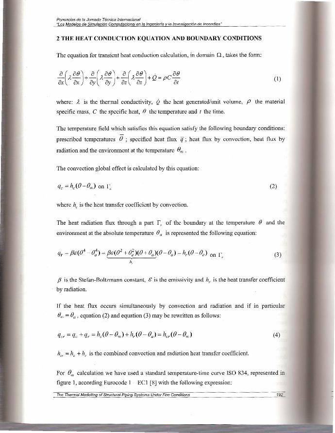
2 THE HEAT CONDUCTION EQUATION AND BOUNDARY CONDITIONS
The equation for transient heat conduction calculation, in domain 0 , takes the form:
(1)
where: A, is the thermal conductivity, Q the heat generated/unit volume, P the material
specific mass, C the specific heat, B the temperature and t the time.
The temperature field which satisfies this equation satisfy the following boundary conditions:
prescribed temperatures () ; specified heat flux q ; heat flux by convection, heat flux by
radiation and the environment at the temperature (Joo .
The convection global effect is calculated by this equation:
(2)
where he is the heat transfer coefficient by convection.
The heat radiation flux through a part r, of the boundary at the temperature B and the
environment at the absolute temperature (}a is represented the following equation:
qr = fJe((}4 -e:) = fJe((}
2 +(},;)((}+fJa)(fJ-fJa) = h,.(fJ-fJa) on r, (3) h,
fJ is the Stefan-Boltzmann constant, £ is the emissivity and h, is the heat transfer coefficient
by radiation.
If the heat flux occurs simultaneously by convection and radiation and if in particular
Boo =()a , equation (2) and equation (3) may be rewritten as follows:
(4)
her =he + h, is the combined convection and radiation heat transfer coefficient.
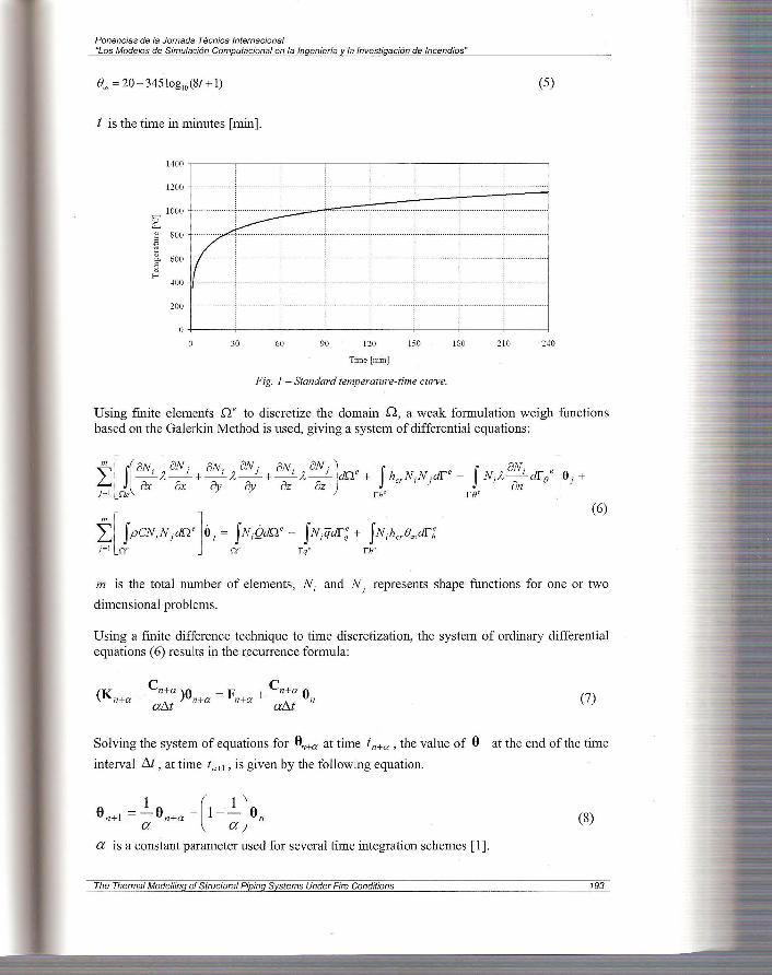
For ()"" calculation we have used a standard temperature-time curve ISO 834, represented in
figure 1, according Eurocode I - ECl [8] with the following expression:
The Thermal Modelling of Structural Piping Systems Under Fire Conditions 192
Ponencias de la Jornada T ecnica lnternacional "Los Mode/os de Simulaci6n Computacional en la lngenieria y la lnvestigaci6n de lncendios"
(5)
t is the time in minutes [min].
1400
1200
1000 G "--" ~ 800
..8 ~
600 ~ ~
400
200
•
• I r . . .. . . , .... . .. .. ... . .. ..
•· ·· ··· · ··· · ·· ···· ·· '··········· • •
~ ,______.
• •
7 •· ······ .... , ..... .... . ...... , ..... ...
... .. ... ..
If •
• • •
•
30 60 90 120 150 180 210 240
Time[min]
Fig. I - Standard temperature-time curve.
Using finite elements ne to discretize the domain Q, a weak formulation weigh functions based on the Galerkin Method is used, giving a system of differential equations:
(6) f[ fpcN;N1dne ]a 1 = fN;Qdne - fN;qdr; + fNAA,drh F 1 n" n ' rq' rh'
m is the total number of elements, N; and NJ represents shape functions for one or two
dimensional problems.
Using a finite difference technique to time discretization, the system of ordinary differential equations ( 6) results in the recurrence formula:
(K Cn+a )9 F Cn+a 9 n+a + --- n+a = n+a + --- n (7)
at....t at....t
Solving the system of equations for 9n+a at time t n+a , the value of 9 at the end of the time
interval t....t , at time t n+1 , is given by the following equation.
on+i = ~ on+a +(1- ~Jon (8)
a is a constant parameter used for several time integration schemes [ 1].
The Thermal Modelling of Structural Piping Systems Under Fire Conditions 193
Ponencias de la Jornada T8cnica lnternacional "LosModelos·de Simulaci6n Computacional en la lngenierla y la lnvestigaci6n de lncendios"
For non-linear problems, where. the thermal material properties are temperature dependent, the
system of equations (6) can generally be written as:
-K(e,r )o(r )+ c(e,r )9(r) = F(e,r) (9)
In order to fully satisfy these non-linear problem conditions, it is necessary to employ an
iterative procedure in each time step. In this algorithm a modified 1\ewton-Raphson method is
adopted [ 1].
2.1 Temperature Determination Inside the Void Based on equation (6) for the heat transfer and considering the following hypotheses, the
product of the specific heat and the air density can be neglected; also the air thermal
conductivity may be neglected when compared with steel thermal conductivity of the
structural element [4-6].
The following equation makes possible the evaluation of the temperature inside the void:
(10)
where NFR is the number of boundary elements at void region and e, is the calculated
temperature at each element node.
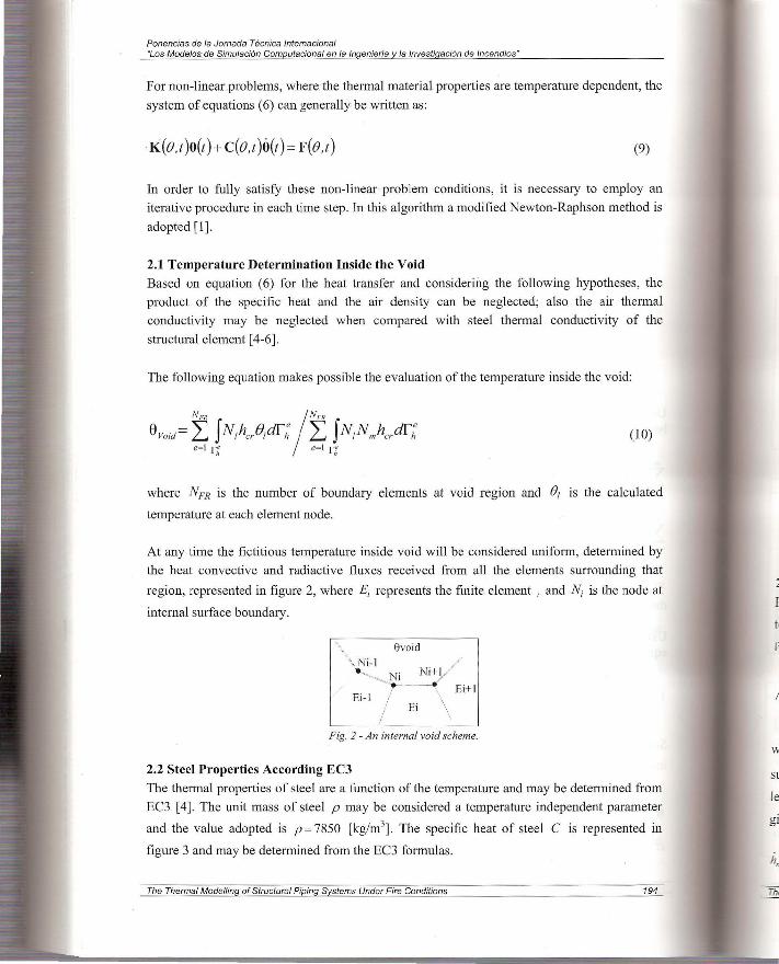
At any time the fictitious temperature inside void will be considered uniform, determined by
the heat convective and radiactive fluxes received fi·om all the elements surrounding that
region, represented in figure 2, where E; represents the finite element ; and N; is the node at
internal surface boundary.
evoid ',, Ni-l
• --...... , Ni Ni+ l ~ ........ --~--
Ei-1 /
/ Ei
El+l
Fig. 2 -An internal void scheme.
2.2 Steel Properties According EC3
The thermal properties of steel are a function of the temperature and may be determined from
EC3 [4]. The unit mass of steel p may be considered a temperature independent parameter
and the value adopted is p = 7850 [kg/m3]. The specific heat of steel C is represented in
figure 3 and may be determined from the EC3 formulas .
The Thermal Modelling of Structural Piping Systems Under Fire Conditions 194
2
F
fi
w
Sl
le
gi

Ponencias de la Jomada Tecnica lntemacional "Los Mode/os de Simulaci6n Computacional en la lngenieria y la lnvestigaci6n de /ncendios"
5400
-t800
4200 '7 ~-· 3600
-==- 3(J\)0 ~ =: 2400 '-" E 1soo ~
600
·-- ---- --- -- ---- ···
---- -- ---- -----
-- --· ·
:!00 400
·· --- - -- -------- -- --- -- - ; --
_.___./ '-i.
600
T emperah1re [''C]
soo
Fig. 3 - Specific heat variation.
.
1000 1200
The thermal conductivity of steel A. is represented in figure 4, according equations from EC3 _
60
.i::' .g ~ 30
5 V ?. E
~ IS
-------i \-- -------.
_.
::!00
-----------~---
400 600
TemperatUJe ['~CJ
I
•
800
Fig 4 - Thermal conductivity variation.
2.3 Simplified Equation According EC3
IOOO 1200
For an equivalent uniform temperature distribution in the cross-section, the increase of
temperature !J.()a.t in an unprotected steel member during a time interval t1t is determined
from the simplified equation from EC3 [4].
e Am i V h-!J. a t=--- netd!J.t , Cp , (11)
where A, I V is the section factor for unprotected steel members [m- 1], A,. is the exposed
surface area of the member per unit length [m2/m], V the volume of the member per unit
length [m3/m], izne~,d the design value of the net heat flux due to convection and radiation
given by the following expression.
- > > 2 hnet ,d = Yn _chnet ,c + Yn, rhnet,r [W/m] (12)
The Thermal Modelling of Structural Piping Systems Under Fire Conditions 195
Ponencias de la Jornada Tecnica lnternacional "Los Mode/os de Simu/aci6n Computacional en la /ngenieria y la lnvestigaci6n de lncendios"
y n,c and Yn,c are equals 1.0, hnet ,c should be calculated according to:
(13)
he may be taken as 25[W/m2K] , em is the surface temperature of the member, Bg is the gas
temperature of the surrounding environment member in fire exposure done by equation 5.
hnet.r is the design value of the heat flux due to radiation given by expression:
(14)
<D is the configuration factor, which should be taken equal unity, er is the radiation
temperature of the environment of the member usually taken as er = ()g, !Y time interval
which should not be taken as more than 5 seconds, &res = 0.5 is the resultant emissivity.
3 CASE STUDY 1: TEMPERATURE VARIATION ACROSS PIPE THICKNESS UNDER FIRE CONDITIONS
The temperature field in structural pipe system is presented, using two and one dimensional
finite element modelling, figure 5.
Only one quarter of section are analysed due to the symmetry of boundary condition and
geometry, when we used two dimensional meshes. For one dimensional mesh we have used
the entire length pipe. The piping system is subjected to external fire conditions, using th~
standard fire curve ISO 834. According to the ECl [8], in the surfaces not exposed to fire, the
convection coefficient is equal a 9[W/m2°K] and the radiation effect is neglected. In th~ surfaces exposed to fire the convection coefficient is equal 25[W/m2°K] and the emissi\i~ equal to 0.5.
Some tubular sections have been studied with different relations between the thickness
the section mean radius h/ r [9].
The results are obtained using the developed code and compared with the solution using -·-
simplified EC3 equation. We considered different situations. First, we used the internal ,. -
theory, second the internal region was considered insulated and finally the internal cavity . _
filled with air.
The figures 6, 7 and 8 represents the temperatures field obtained in thick curved pipes ar .
different times, using a two dimensional mesh.
The Thermal Modelling of Structural Piping Systems Under Fire Conditions

Ponencias de la Jornada Tecnica lnternacional "Los Mode/os de Simu/aci6n Computaciona/ en la /ngenieria y la lnvestigaci6n de /ncendios"
Fig. 5- The curved pipe under fire conditions. Meshes used in developed code.
172.4Q41DIDiill!l
7 1.1!1 5SiilGJI!JI!.I
~, ~89. 7S71!ll!li!ll!l
' ' S4 .3141!l llHil61
I S2 . 9SS611!Hl61
~s 1 • s 1 Slilrillili!l
6. T= 10. 79[°C]
114S .2261i!ll!llll
144 . 351!)QI!)ilJ
"-~ 142 . 49(11!H!IIll
L~''- 141.il . S2(1161(11(11
i!b~ 138.75611lll!lGJ , , 13S.88GJ(!ll!l(ll
IT::t t35.€11(!li91Di!l
133 .1 5ilJ(!l(ll(ll
131.2861(1119(11
6. T= 14.94[0 C]
Fig. 6 - The temperature field obtained with internal insulated region (thickness 40 [mm}).
1- ~ ' s3.47SI!l(!ll'ill!l
S2.121lll'il(!ll!ll'il
Sl!l.7S41DiilliH\I
T=10.85(0 C]
6. T= 10. 77[°C]
Fig. 8- The temperature field obtained with internal void (thickness 40 [mm}).
The Thermal Modelling of Structural Piping Systems Under Fire Conditions
Tern erature
1145 .3UIDIDID
143.431DiiiiDISI
'141 . 56019@@
L'!T=15.0l(0 CJ
L'lT=14.89[0C]
197
Ponencias de la Jornada Tecnica lnternacional "Los Mode/os de Simulaci6n Computacional en la lngenieria y la lnvestigaci6n de lncendios"
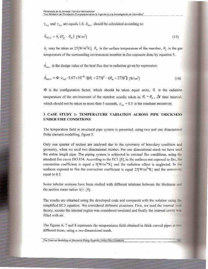
Changing the relation h/ r, the temperature cross the pipe thickness varies also and the
simplified equation does not correspond to a real value. The same is applied for the one
dimensional mesh, because the temperature calculation is determined for the medium pipe
surface. So the one dimensional modelling may be applied to thin structural piping systems
giving good results. Figures 9 and 10 show the temperature evolution for two of different
relation tubes h/ r , obtained using the two dimensional and one dimensional meshes at node
of mean radius. The results are compared with the simplified heat equation.
120
u ~ 100 s ~ so ::>.
~ 60 1-
40
0 100 200 Time[s] 300 400 500
-e- Simplified equation EC.l ..,... (I D) Pipe Element ---(7- (2D)_Insulated
...,._ (2D)_Cavity ~ (2Dl_Modelled air
Fig. 9 - Time history of temperature of tube with the relation h/ r = 0. 23 5.
-e-Smlplified equation EC3 -><-( ID) Pipe Element -+-(2D)_[nsulated
...,._ (2D)_ CaYity ~ (2Di_ Modelled air
Fig. 10 - Time hisiory of temperature of tube with the relation h/ r = 0. 007 .
600
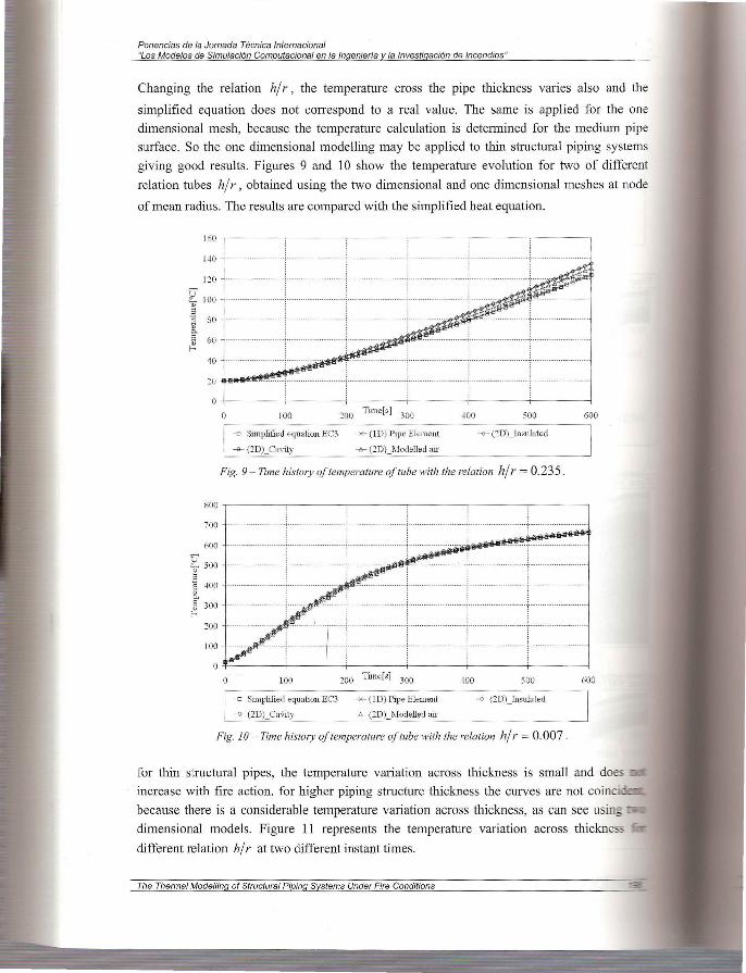
for thin structural pipes, the temperature variation across thickness is small and does
increase with fire action. for higher piping structure thickness the curves are not coinci
because there is a considerable temperature variation across thickness, as can see using
dimensional models. Figure 11 represents the temperature variation across thickne-
different relation h/ r at two different instant times.
The Thermal Modelling of Structural Piping Systems Under Fire Conditions

Ponencias de la Jornada Tecnica lnternacional "Los Mode/os de Simulaci6n Computacional en la lngenieria y la lnvestigaci6n de lncendios"
In circular pipe sections due the axisymmetrie, considering the some boundary condition
along the section radius, the inside surface temperature is uniform. As temperature is unifmm
inside voids, heat flux by radiation should not be considered, neglecting this type of heat transfer in structural piping systems. Temperature gradient across pipe thickness decrease has been verified for thin structural pipes and a uniform temperature may be considered as well the simplified heat equation EC3 proposes. So it is possible to obtain the temperature field for
thin structural piping systems using one dimensional finite element mod.el.
j ~~
10
0 .0~ 0.04 0 .06 fJ.OS tU h/r(l _l1. 0.14 0.16 fJ .I S 0 .1 O.l l 0.::!4
Fig. 11 - Temperature variation across pipe thickness.
4 CASE STUDY 2: TEMPERATURE CALCULATION OF A STRUCTURAL PIPING SYSTEM UNDER FIRE CONDITIONS
The structural piping system presented is composed by six elbows of 90° ASTM A234 and
seven straight pipes ASTM Al06 subjected to external fire conditions, figure 12. The mean radius is equal to 44.62 [mm] and the thickness is 4 [mm]. The curvature radius is 57.2 [mm].
All pipes have the same length equal to 100 [mm].
The material considered is steel and the all properties are according to EC3. A one
dimensional mesh will be used, based on the new finite element formulation developed [9].
Comparison with a three dimensional finite shell element will be presented based on a
commercial finite element programme Cosmos/M.
Fig. 12- Finites elements used.
The Thermal Modelling of Structural Piping Systems Under Fire Conditions 199

Ponencias de la Jornada Tecnica lnternacional "Los Mode/os de Simulaci6n Computacional en la lngenieria y la tnvestigaci6n de lncendios"
Develo
1·27.1 2 1 ~'''
27.1 2 1 ~1188
27 .1 2 llil888
Fig. 13 - Temperature field at final time 20 [s}.
1195.SIIlt888
195,SSS81ll8
JS5.:911lfi8 U
Fig. 14 - Temperature field at final time 200 [s}.
I"·'""" 2:8 . 2348888
, , .. 1
25 . H418t8
Fig. 15 - Temperature field at final time 20 [s}
Fig. 16 - Temperature field at final time 200 [s}.
The Thermal Modelling of Structural Piping Systems Under Fire Conditions
I"'·" 1:91 . 43
1:97.43
. :Z.I66
1.,,..,
.
11::~ . 2e
. 153 . 12
Kt llii . S$

Ponencias de fa Jornada Tecnica lnternacional "Los Mode/os de Simulaci6n Computacional en la lngenieria y la lnvestigaci6n de lncendios"
For this fire condition; temperature distribution is considered constant across section mean
radius and along piping system, because we have considered all the piping system exposed to
this thermal action. The figures 13 and 14 represent the nodal temperatures at two different time steps using the referred models.
A new analysis will be presented for the same structural piping system, considering an
insulated upper zone with other parts subjected to fire conditions. In figures 15 and 16 a
comparison between the new formulation and the commercial code is presented for two
distinct instant times. The results present good agreement and the insulated zone maintain the
uniform initial temperature at 20 [0 C].
5 CONCLUSIONS
A computational program based on the finite element method was presented to study thermal
model behaviour of piping systems subjected to fire conditions. The internal void temperature
calculation in a structural element may be calculated using simplified formulas and reducing the computing effort when compared with other methods. The results of a transient temperature field obtained with the developed code have been compared with the results
obtained with the simplified heat conduction equation and with the results obtained from 3D
meshes derived from commercial codes. Based in the analysed cases studies, it may be
concluded that for thin piping systems the temperature field can be obtained with less
computational effort using one dimensional mesh for an external axisymmetric boundary
condition.
REFERENCES
1. Vila Real, P. M. M. , Modela~ao por Elementos Finitos da Solidifica~ao e Comportamento
Termo-Medinico de Pe~as Vazadas em Molda~oes Metalicas, 1993, PhD thesis, Faculty
of Engineering of University ofPorto, Porto. 2. Fonseca E., Vila Real P., Finite Element Modelling ofThermo-Elastoplastic Behaviour of
Hot-Rolled Steel Profiles Submitted to Fire, IV Congresso de Metodos Numericos en
Ingenieria, (R. Abascal, J. Dominguez y G. Bugeda, Eds.), SEMNI- Sociedad Espafiola
de Metodos Numericos en Ingenieria, 1999, ISBN: 84-89925-45-3.
3. Fonseca E. M. M. , Oliveira C. A. M., Melo F. Q., Validac;ao Experimental de urn Modelo
Te6rico para Cilculo de Elevados Gradientes Termicos em Estruturas de Parede Fina,
Revista da AP AET - Associa~ao Portuguesa de Analise Experimental de Tensoes, ISSN-
122 922, Vol.n°8, 2002, pp. 41-48. 4. CEN ENV 1993-1-2, Eurocode 3: Design of Steel Structures - Part 1.2: General Rules
Structural Fire Design, 1995.
5. Franssen J. M., Elements of Theory for SAFIR 2001 free. A Computer Program for
Analysis of Structures Submitted to the Fire, 2002, University of Liege, Belgium.
The Thermal Modelling of Structural Piping Systems Under Fire Conditions 201
Ponencias de la Jornada Tecnica lnternacional "Los Mode/os de Simulaci6n Computacional en la lngenierfa y la lnvestigaci6n de lncendios"
6. Wickstrom U., Palsson J., A Scheme for Verification of Computer Codes for Calculating
Temperatures in Fire Exposed Structures, SP Swedish National Testing and Research
Institute, Fire Technology, 1999, SP Report 36.
7. Fonseca E. M. M., Oliveira C. A. M. , Numerical Modelling of Internal Voids in Fire
Exposed Structures, (Jose 0. Valderrama, Carlos J. Rojas, Eds.), so Interamerican
Congress on Computers Applied to the Process Industry, Brasil, 2001, ISBN: 956-291-
077-6, pp.195-199.
8. CEN ENV 1991-2-2, Eurocode 1, Basis of Design and Actions on Structures - Pati 2-2:
Actions on Structures- Actions on Structures Exposed to Fire, 1995.
9. Fonseca E. M. M., Analise por Elementos Finitos do Comportamento de Tubagens sob a
Acc;ao de Fortes Gradientes Terrnicos, 2003, PhD thesis, Faculty of Engineering of
University ofPorto, Porto.
The Thermal Modelling of Structural Piping Systems Under Fire Conditions